Embed Size (px)
Citation preview
SLEEVEIT 1224R SYSTEM
FENCE AND PEDESTRIAN RAIL FOUNDATION
Strata Systems, Inc. 380 Dahlonega Road, Ste 200 Cumming, GA 30040
Phone: (770) 888-6688 Fax: (770) 888-6680 www.geogrid.com

Page 2 of 11 Version 2011_F
Sleeve‐It 1224R System – Fence and Pedestrian Rail Foundation for Segmental Retaining Walls
Introduction The segmental retaining wall industry is the mainstay of vertical grade separation structures for residential, commercial and private sector markets. Segmental retaining walls have become a part of many state highway department and federal highway administration projects. The inherit benefit of a dry‐cast, mortarless retaining wall construction; ease of construction, economic structures, and hand‐placed units, is in part a detriment to one important consideration that is critical in almost every project – lateral resistance for fence or pedestrian rail foundations .
Light‐weight units combined with mortarless construction result in wall systems that have limited stability when not combined with soil reinforcement. Most segmental retaining wall systems incorporate relatively light‐weight units (approx. 60 to 80 lbs each) having nominal dimension of 6 to 8 inches high by 12 inches wide (depth from front of unit to rear of unit) and 16 to 18 inches long (length along the wall face. These wall systems are typically stable without soil reinforcement up to vertical heights of 2 to 4 feet, retaining only soil fill. If a fence or pedestrian rail post is placed directly behind the unit even when encased in a 12” diameter by 24” deep concrete foundation, then the system is unable to provide adequate resistance against overturning and/or sliding and will not meet building code requirements for fall protection.
The Sleeve‐It 1224R System is design specifically to address the need for small post foundations placed directly behind segmental retaining wall systems. The Sleeve‐It System incorporates a cantilever base with a 12” diameter by 24” deep column foundation to provide the necessary lateral and uplift resistance to meet published building codes. The cantilever base uses D‐4 and D‐7 wire complying with ASTM A496, and the fabrication complies with ASTM A497. Two struts, comprised of W‐4 wire meeting ASTM A82, are used to lateral restrain the vertical leg of the cantilever base and transfer lateral load from the post foundation to the cantilever base. The 12” diameter post foundation is comprised of two interlocking HDPE sleeve components that are field connected and provide openings for the two cantilever base struts. All portions of the cantilever base and struts that are not embedded in concrete are treated with an epoxy phenolic primer and then dipped in a proprietary PVC coating bonded by thermal fusion.
The Sleeve‐It 1224R System utilizes a cantilever base system to provide increased resistance to sliding forces and overturning moments induced when a load is applied to a fence or pedestrian rail. The 1224R system behaves in much the same manner as a conventional cantilever wall system. The cantilever base extends the width of the 24” concrete post foundation, thus providing greater resistance to lateral sliding and uplift or overturning. The soil mass directly above the base adds vertical weight
Page 3 of 11 Version 2011_F
while the passive resistance developed during soil uplift provides further resistance to overturning. The increased capacity provides an effective fence and pedestrian post foundation system that meets building code requirements.
Building Codes – Residential and Commercial Both residential and commercial building codes specifically state guards shall be provided when the vertical grade between different surfaces exceed a fixed vertical height. Commercial codes further define minimum load requirements that the guards are to provide. The codes are generally interpreted to require guards (protection) atop retaining wall structures and are applicable to fencing and pedestrian rail systems placed atop segmental retaining wall systems.
Residential Codes The International Residential Code (IRC) states, Section R312 ‐ Guards, that guards are required when raised surfaces are located more than 30 inches above the floor or grade below. The guard shall not be less than 36 inches (3 feet) in height. The requirement for guards applies to porches, balconies, decks, ramps and raised surfaces (i.e. retaining walls).
Commercial Codes The International Building Code (IBC) states, Section 1013 – Guards, that guards shall be located along open‐sided walking surfaces, mezzanines, industrial equipment platforms, stairways, ramps and landings that are located more than 30 inches above the floor or grade below. The guard shall provide adequate strength to meet the load requirements of Section 1607.7. Section 1607.7.1 requires guards and handrails to resist a load of 50 pounds per linear foot applied along the top, and Section 1607.7.1.1 states the assemblies and guards shall be able to resist a single concentrated load of 200 pound applied along the top.
Based on Section 1607.7.1, the minimum load required to be resisted will be a function of post spacing. The following table summarizes several common posts spacing and corresponding load condition.
Post Spacing (ft) Applied Load (lbs)Single Post (concentrated load) 2004‐ft post spacing 2006‐ft post spacing 3008‐ft post spacing 40010‐ft post spacing 500
The table above has several implications regarding required post or foundation capacity depending on the location of applied load. The building codes indicate the load shall be applied atop the guard. This implies the load shall be applied atop the post, which will result in an applied moment that is a function of both the post height and the post spacing. The following
Page 4 of 11 Version 2011_F
table indicates the minimum required moment as a function of post height or location of applied load above a 24‐inch deep foundation.
Post Spacing (ft) Applied Load (lbs)
3‐ft Post above 24‐inch Deep Foundation (minimum guard
height per IRC)
6‐ft Post above 24‐inch Deep Foundation
Location of Applied Load
(ft)
Applied Moment (lb‐ft)
Location of Applied Load
(ft)
Applied Moment (lb‐ft)
Single Post (concentrated load)
200 5 1000 8 1600
4‐ft post spacing 200 5 1000 8 16006‐ft post spacing 300 5 1500 8 24008‐ft post spacing 400 5 2000 8 320010‐ft post spacing 500 5 2500 8 4000
It is generally inferred that fences or pedestrian rails (i.e. guards) are required atop any segmental retaining wall exceeding 30 inches in exposed height as a means of providing fall protection to the public. The Sleeve‐It 1224R system is engineered to meet the IRC and IBC requirements for guards – fence and pedestrian rail systems.
SleeveIt 1224R Testing
Product Development Testing (2005) The development of the Sleeve‐It 1224R System included full‐scale load test to document the structural capacity of the system as well as documenting the insufficient capacity of conventional 12‐inch diameter, 24‐inch deep concrete post foundations placed directly behind segmental retaining units.
Initial development testing was formulated based on a review of the Pennsylvania Department of Transportation (PennDOT) fence post testing performed in the 1970 and a 2001 study of fence post anchoring systems published by Rutgers University in cooperation of the New Jersey Department of Transportation and the U.S. Department of Transportation Federal Highway Administration. The PennDOT study involved applying load at the top of conventional fence post installed in a standard foundation with sufficient lateral resistance on all sides. The PennDOT study indicated the post failed prior to the foundation and additional research is required. The Rutgers study involved installing post in a fully‐lateral supported foundation and applying a load at 24‐inches above grade, which is consistent with the typical height of a vehicle bumper. The Rutgers study found the foundations consistently failed prior to the post.
The initial development testing considered an applied load located 24‐inches above grade and included 9 tests with steel fence posts. The tests were conducted with schedule 40 (steel) posts, commonly referred to as 2.5 inch line posts. The test program was divided as follows:
Page 5 of 11 Version 2011_F
(3) Tests – 12” diam. By 24” deep forms without Sleeve‐It System – Tests 1A, 1B, 1C (3) Tests – Prototype Sleeve‐It 1224R – Tests 2A, 2B, 2C (3) Tests – Prototype Sleeve‐It 1224R with one layer of geogrid reinforcement
approximately 8‐inches above the cantilever base (or 16 inches below the top of wall) – Tests 3A, 3B, 3C
All posts foundations were filled with ready mix concrete, 3000 psi, ¾‐inch (max.) aggregate size, delivered to the test site by a local supplier
The posts foundations were installed as part of the construction for a 90‐ft long by 52‐inch high segmental retaining wall built in general accordance with manufacturers guidelines. The wall units utilized were nominally 8” high by 12” deep by 18” long with open core filled with aggregate. The units were installed without pins, clips or other concrete alignment devices. Backfill soil consisted primarily of silt with some clay and trace of sand and was compacted in 8‐inch lifts. Compaction was performed wet of optimum to simulate worst case conditions.
Load test were performed using a Come‐Along ratcheting cabled winch mechanism with inline S‐type load cell. The system was attached to the post at 24‐inches above grade and secured to a dead man, a Case tracked excavator with a gross vehicle weight of 29000 lbs. Deflection was manually measured to the nearest 1/16 inch.
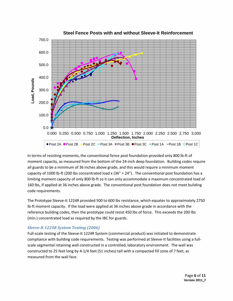
The results of the test are summarized in the graph below. The data indicates the conventional 12‐inch diameter, 24‐inch deep concrete post foundation with an applied load located at 24‐inches above grade provided a maximum resistance of 200 lbs. The six (6) tests incorporating the Prototype Sleeve‐It 1224R provided a maximum resistance of 500 to 600 lbs.
Page 6 of 11 Version 2011_F
In terms of resisting moments, the conventional fence post foundation provided only 800 lb‐ft of moment capacity, as measured from the bottom of the 24‐inch deep foundation. Building codes require all guards to be a minimum of 36 inches above grade, and this would require a minimum moment capacity of 1000 lb‐ft (200 lbs concentrated load x (36” + 24”). The conventional post foundation has a limiting moment capacity of only 800 lb‐ft so it can only accommodate a maximum concentrated load of 160 lbs, if applied at 36 inches above grade. The conventional post foundation does not meet building code requirements.
The Prototype Sleeve‐It 1224R provided 500 to 600 lbs resistance, which equates to approximately 2750 lb‐ft moment capacity. If the load were applied at 36 inches above grade in accordance with the reference building codes, then the prototype could resist 450 lbs of force. This exceeds the 200 lbs (min.) concentrated load as required by the IBC for guards.
SleeveIt 1224R System Testing (2006) Full‐scale testing of the Sleeve‐It 1224R System (commercial product) was initiated to demonstrate compliance with building code requirements. Testing was performed at Sleeve‐It facilities using a full‐scale segmental retaining wall constructed in a controlled, laboratory environment. The wall was constructed to 25 feet long by 4‐1/4 feet (51 inches) tall with a compacted fill zone of 7 feet, as measured from the wall face.
0.0
100.0
200.0
300.0
400.0
500.0
600.0
700.0
0.000 0.250 0.500 0.750 1.000 1.250 1.500 1.750 2.000 2.250 2.500 2.750 3.000
Load
, Pou
nds
Deflection, Inches
Steel Fence Posts with and without Sleeve-It Reinforcement
Post 2A Post 2B Post 2C Post 3A Post 3B Post 3C Post 1A Post 1B Post 1C
Page 7 of 11 Version 2011_F
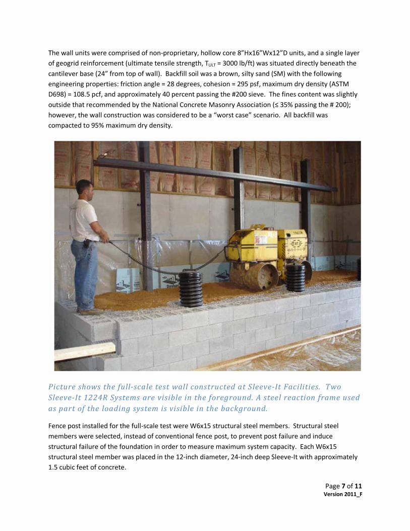
The wall units were comprised of non‐proprietary, hollow core 8”Hx16”Wx12”D units, and a single layer of geogrid reinforcement (ultimate tensile strength, TULT = 3000 lb/ft) was situated directly beneath the cantilever base (24” from top of wall). Backfill soil was a brown, silty sand (SM) with the following engineering properties: friction angle = 28 degrees, cohesion = 295 psf, maximum dry density (ASTM D698) = 108.5 pcf, and approximately 40 percent passing the #200 sieve. The fines content was slightly outside that recommended by the National Concrete Masonry Association (≤ 35% passing the # 200); however, the wall construction was considered to be a “worst case” scenario. All backfill was compacted to 95% maximum dry density.
Picture shows the fullscale test wall constructed at SleeveIt Facilities. Two SleeveIt 1224R Systems are visible in the foreground. A steel reaction frame used as part of the loading system is visible in the background.
Fence post installed for the full‐scale test were W6x15 structural steel members. Structural steel members were selected, instead of conventional fence post, to prevent post failure and induce structural failure of the foundation in order to measure maximum system capacity. Each W6x15 structural steel member was placed in the 12‐inch diameter, 24‐inch deep Sleeve‐It with approximately 1.5 cubic feet of concrete.
Page 8 of 11 Version 2011_F
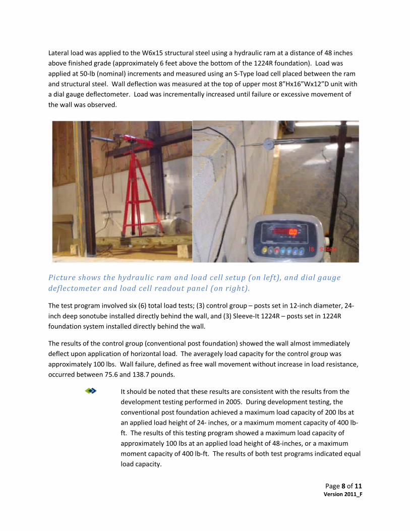
Lateral load was applied to the W6x15 structural steel using a hydraulic ram at a distance of 48 inches above finished grade (approximately 6 feet above the bottom of the 1224R foundation). Load was applied at 50‐lb (nominal) increments and measured using an S‐Type load cell placed between the ram and structural steel. Wall deflection was measured at the top of upper most 8”Hx16”Wx12”D unit with a dial gauge deflectometer. Load was incrementally increased until failure or excessive movement of the wall was observed.
Picture shows the hydraulic ram and load cell setup (on left), and dial gauge deflectometer and load cell readout panel (on right).
The test program involved six (6) total load tests; (3) control group – posts set in 12‐inch diameter, 24‐inch deep sonotube installed directly behind the wall, and (3) Sleeve‐It 1224R – posts set in 1224R foundation system installed directly behind the wall.
The results of the control group (conventional post foundation) showed the wall almost immediately deflect upon application of horizontal load. The averagely load capacity for the control group was approximately 100 lbs. Wall failure, defined as free wall movement without increase in load resistance, occurred between 75.6 and 138.7 pounds.
It should be noted that these results are consistent with the results from the development testing performed in 2005. During development testing, the conventional post foundation achieved a maximum load capacity of 200 lbs at an applied load height of 24‐ inches, or a maximum moment capacity of 400 lb‐ft. The results of this testing program showed a maximum load capacity of approximately 100 lbs at an applied load height of 48‐inches, or a maximum moment capacity of 400 lb‐ft. The results of both test programs indicated equal load capacity.
Page 9 of 11 Version 2011_F
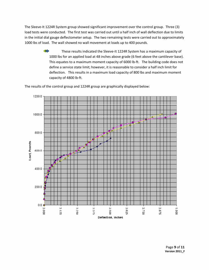
The Sleeve‐It 1224R System group showed significant improvement over the control group. Three (3) load tests were conducted. The first test was carried out until a half inch of wall deflection due to limits in the initial dial gauge deflectometer setup. The two remaining tests were carried out to approximately 1000 lbs of load. The wall showed no wall movement at loads up to 400 pounds.
These results indicated the Sleeve‐It 1224R System has a maximum capacity of 1000 lbs for an applied load at 48 inches above grade (6 feet above the cantilever base). This equates to a maximum moment capacity of 6000 lb‐ft. The building code does not define a service state limit; however, it is reasonable to consider a half inch limit for deflection. This results in a maximum load capacity of 800 lbs and maximum moment capacity of 4800 lb‐ft.
The results of the control group and 1224R group are graphically displayed below:
Page 10 of 11 Version 2011_F
Research Results / System Limits The Sleeve‐It 1224R System is a pre‐engineered foundation system for fence and pedestrian rail applications that meets or exceed IRC and IBC code requirements for ‘guards’ or fall protection for the general public. The limits of the system are a function of post spacing and applied load location as measured from finished grade or bottom of the foundation system. The following table provides general guidance for the Sleeve‐It 1224R System limits relative to the ‘system limits’ as determined from full‐scale load tests. In each case, the maximum moment capacity is less than or equal to the Full‐Scale Load Test (System Limits) condition.
Load Condition Applied Load Height above 1224R cantilever (ft)
Applied Load(lbs)
Post Spacing(ft)
Applied Moment Capacity (lb‐ft)
Full‐Scale Load Test (System Limits)
6 800 at ½‐inch deflection
N/A 4800
10‐ft Fence Application
12 200 lbs concentrated or 50 lb/ft
8 4800
8‐ft Fence Application
10 200 lbs concentrated or 50 lb/ft
8 4000
6‐ft Fence Application
8 200 lbs concentrated or 50 lb/ft
10 4000
4‐ft Fence Application
6 200 lbs concentrated or 50 lb/ft
10 3000
36‐inch Pedestrian Rail
5 200 lbs concentrated or 50 lb/ft
6 1500
42‐inch Pedestrian Rail
5.5 200 lbs concentrated or 50 lb/ft
8 2200
System Guidance The Sleeve‐It 1224R System has been tested using a pseudo‐static load condition and has not been tested for dynamic load conditions such as those induced by wind or similar load applications. The Sleeve‐It 1224R system IS NOT appropriate for the following applications:
1. Fencing systems that employ wind screen fabrics. 2. Sound barrier or other conventional privacy wall structures. 3. Solid board privacy fences. 4. Fence systems where the vertical post height exceed 10 feet or post spacing exceeds 12 feet,
without technical review by Strata Systems, Inc.
Page 11 of 11 Version 2011_F
The Sleeve‐It 1224R System is an appropriate foundation for the following applications:
1. Sleeve‐It 1224R System cantilever base located 24‐inches below finished grade. 2. Pedestrian Rail Systems limited to 42” height and maximum post spacing of 8 feet. 3. Fence Systems ‐
a. Chain Link: Post – 8 feet above finished grade, Spacing 8 feet maximum b. Ornamental (Steel, Aluminum, Wrought Iron) Post – 6 feet above finished grade,
Spacing 10 feet maximum c. Open Board / Gap Board (70% open): Post – 6 feet above finished grade, Spacing 6 feet
maximum 4. The use of privacy cloth or screening is STRICTLY PROHIBITED.
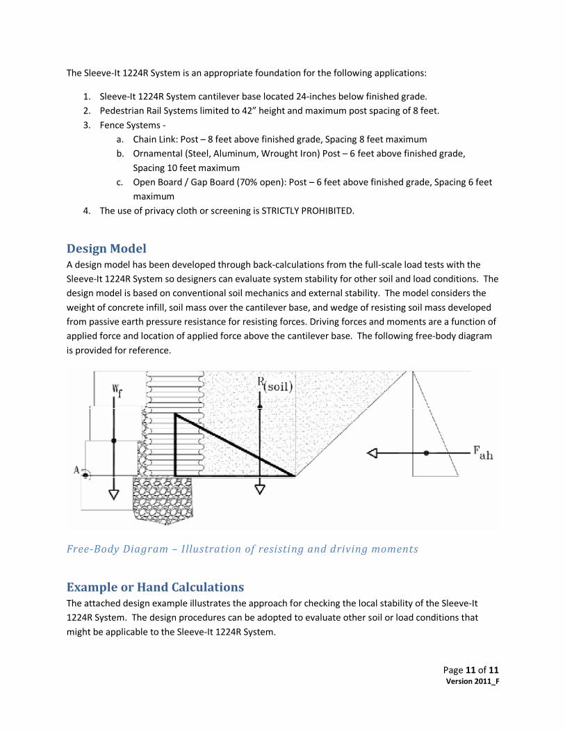
Design Model A design model has been developed through back‐calculations from the full‐scale load tests with the Sleeve‐It 1224R System so designers can evaluate system stability for other soil and load conditions. The design model is based on conventional soil mechanics and external stability. The model considers the weight of concrete infill, soil mass over the cantilever base, and wedge of resisting soil mass developed from passive earth pressure resistance for resisting forces. Driving forces and moments are a function of applied force and location of applied force above the cantilever base. The following free‐body diagram is provided for reference.
FreeBody Diagram – Illustration of resisting and driving moments
Example or Hand Calculations The attached design example illustrates the approach for checking the local stability of the Sleeve‐It 1224R System. The design procedures can be adopted to evaluate other soil or load conditions that might be applicable to the Sleeve‐It 1224R System.
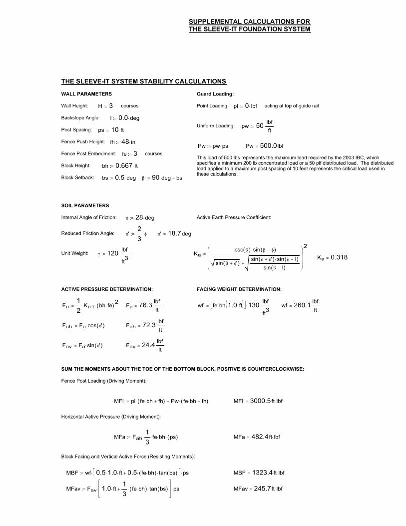
Active Earth Pressure Coefficient:
Reduced Friction Angle: �'23
���� �' 18.7deg�
Unit Weight: � 120 lbf
ft3��� Ka
csc �( ) sin � ��( )�
sin � �'( )sin � �'( ) sin � I�( )�
sin � I�( )
���
���
2��
Ka 0.318�
ACTIVE PRESSURE DETERMINATION: FACING WEIGHT DETERMINATION:
Fa12
Ka� �� bh fe�( )2��� Fa 76.3 lbfft
� wf fe bh� 1.0 ft�� ��� �� 130�lbf
ft3��� wf 260.1 lbf
ft�
Fah Fa cos �'( )��� Fah 72.3 lbfft
�
Fav Fa sin �'( )��� Fav 24.4 lbfft
�
SUM THE MOMENTS ABOUT THE TOE OF THE BOTTOM BLOCK, POSITIVE IS COUNTERCLOCKWISE:
Fence Post Loading (Driving Moment):
MFI pl fe bh� fh( )� Pw fe bh� fh( )��� MFI 3000.5 ft lbf��
Horizontal Active Pressure (Driving Moment):
MFa Fah13
� fe� bh� ps( )��� MFa 482.4ft lbf��
Block Facing and Vertical Active Force (Resisting Moments):
MBF wf 0.5 1.0� ft� 0.5 fe bh�( )� tan bs( )��� ��� ps��� MBF 1323.4 ft lbf��
MFav Fav 1.0 ft�13
fe bh�( )� tan bs( )����
���
� ps��� MFav 245.7ft lbf��
SUPPLEMENTAL CALCULATIONS FORTHE SLEEVE-IT FOUNDATION SYSTEM
PREPARED BY BART SHIPPEE, P.E.ADVANCED HARDSCAPE SOLUTIONS LLC
NOVEMBER 28, 2005
THE SLEEVE-IT SYSTEM STABILITY CALCULATIONS
WALL PARAMETERS Guard Loading:
Wall Height: H 3�� courses Point Loading: pl 0 lbf��� acting at top of guide rail
Backslope Angle: I 0.0 deg���Uniform Loading: pw 50 lbf
ft���
Post Spacing: ps 10 ft���
Fence Push Height: fh 48 in���Pw pw ps��� Pw 500.0lbf�
Fence Post Embedment: fe 3�� coursesThis load of 500 lbs represents the maximum load required by the 2003 IBC, which specifies a minimum 200 lb concentrated load or a 50 plf distributed load. The distributed load applied to a maximum post spacing of 10 feet represents the critical load used in these calculations.
Block Height: bh 0.667 ft���
Block Setback: bs 0.5 deg��� � 90 deg� bs���
SOIL PARAMETERS
Internal Angle of Friction: � 28 deg���
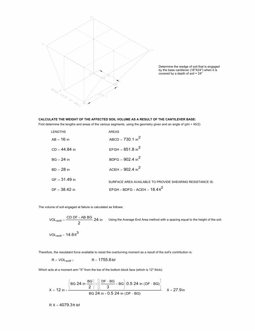
R X� 4079.3 ft lbf��
X 27.9 in�X 12 in�
BG 24� in�BG
2�
��
��
DF BG�
3BG
��
��
0.5� 24� in� DF BG�( )����
���
BG 24� in� 0.5 24� in� DF BG�( )���
Which acts at a moment arm "X" from the toe of the bottom block face (which is 12" thick):
R 1755.6 lbf�R VOLsoil ����
Therefore, the resulatant force available to resist the overturning moment as a result of the soil's contribution is:
VOLsoil 14.6 ft3�
Using the Average End Area method with a spacing equal to the height of the soil.VOLsoilCD DF� AB BG�
224� in���
The volume of soil engaged at failure is calculated as follows:
EFGH BDFG ACEH 18.4 ft2�DF 38.42 in���
SURFACE AREA AVAILABLE TO PROVIDE SHEARING RESISTANCE IS:GF 31.49 in���
ACEH 902.4 in2���BD 28 in���
BDFG 902.4 in2���BG 24 in���
EFGH 851.8 in2���CD 44.84 in���
ABCD 730.1 in2���AB 16 in���
AREASLENGTHS
First determine the lengths and areas of the various segments, using the geometry given and an angle of (phi + 45/2)CALCULATE THE WEIGHT OF THE AFFECTED SOIL VOLUME AS A RESULT OF THE CANTILEVER BASE:
Determine the wedge of soil that is engagedby the base cantilever (16"X24") when it iscovered by a depth of soil = 24"
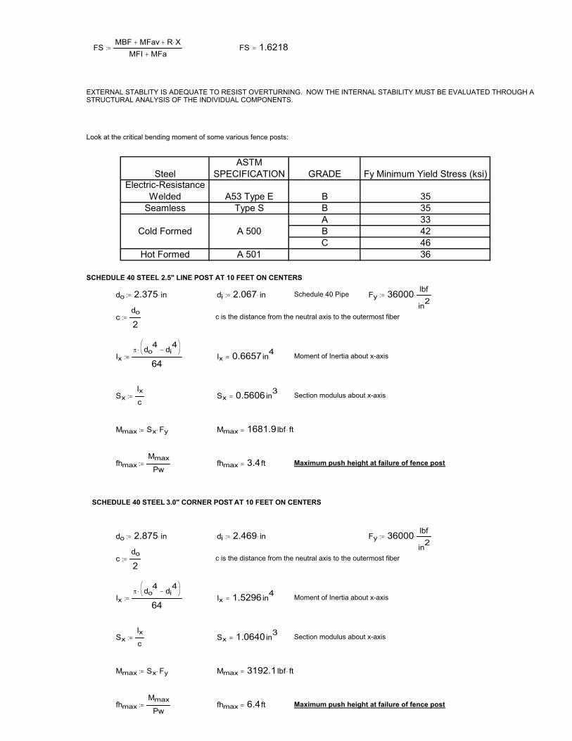
fhmaxMmax
Pw�� fhmax 3.4ft� Maximum push height at failure of fence post
SCHEDULE 40 STEEL 3.0" CORNER POST AT 10 FEET ON CENTERS
do 2.875 in��� di 2.469 in��� Fy 36000 lbf
in2���
cdo
2�� c is the distance from the neutral axis to the outermost fiber
Ix� do
4 di4
�� ��
64�� Ix 1.5296in4
� Moment of Inertia about x-axis
SxIxc
�� Sx 1.0640in3� Section modulus about x-axis
Mmax Sx Fy��� Mmax 3192.1 lbf ft��
fhmaxMmax
Pw�� fhmax 6.4ft� Maximum push height at failure of fence post
FSMBF MFav R X�
MFI MFa�� FS 1.6218�
EXTERNAL STABLITY IS ADEQUATE TO RESIST OVERTURNING. NOW THE INTERNAL STABILITY MUST BE EVALUATED THROUGH A STRUCTURAL ANALYSIS OF THE INDIVIDUAL COMPONENTS.
Look at the critical bending moment of some various fence posts:
SteelASTM
SPECIFICATION GRADE Fy Minimum Yield Stress (ksi)Electric-Resistance
Welded A53 Type E B 35Seamless Type S B 35
A 33Cold Formed A 500 B 42
C 46Hot Formed A 501 36
SCHEDULE 40 STEEL 2.5" LINE POST AT 10 FEET ON CENTERS
do 2.375 in��� di 2.067 in��� Schedule 40 Pipe Fy 36000 lbf
in2���
cdo
2�� c is the distance from the neutral axis to the outermost fiber
Ix� do
4 di4
�� ��
64�� Ix 0.6657in4
� Moment of Inertia about x-axis
SxIxc
�� Sx 0.5606in3� Section modulus about x-axis
Mmax Sx Fy��� Mmax 1681.9 lbf ft��

The above calculations indicate that i) Schedule 40 steel fence posts will fail before the Sleeve-It Sytem fails; ii) The Sleeve-It System has significant additional capacity beyond that required by the 2003 IBC; iii) The theoretical method of failure of the Sleeve-It System is that the hooks will unravel under loads well beyond those required to satisfy 2003 IBC, which is a controlled method of failure and the failure is independent of soil type (i.e., friction angle and unit weight).
SINCE OB > Pw THE STRUTS WILL NOT FAIL AT THE MAXIMUM REQUIRED IBC LOADING.
AB 584.9lbf�
AB OA sin �( )���
Maximum horizontal force available for the two struts at peak loadOB 835.6lbf�
OB OA cos �( )���
OA 1020 lbf���
O
B
A
w is the angle from horizontal made by the strut� 35.0deg�� atan1420
��
��
��
From the strut and cantilever geometry, the upright leg to the rear hook of the strut is 20" horizontally and the strut vertical height is 14".
This is the maximum load of 50 plf applied at the maximum post spacing of 10 feetPw 500.0lbf�
Now look at the vector geometry of the strut configuration and verify that the horizontal component of the maximum load capacity is greater than the horizontal force being applied as a result of IBC 2003.
Load capacity of 1224R strutsStrutLoad 1020.0 lbf�
StrutLoad Strutcapac StrutNum���
Number of struts for the Sleeve-It 1224RStrutNum 2��
Structural capacity of a single strutStrutcapac 510 lbf���
Based on empirical test data, the maximum force a 1224R strut with a hooked end can withstand before yielding (uncurling) is 510 lbs.


![Total Solution for Oil and Gas Testing [ZH] · 2019-03-20 · astm d3710 astm d7096 astm d5399 astm d2887 astm d5442 astm d7213 astm d6417 astm d6352 astm d5307 astm d7500 astm d7169](https://img.pdfslide.net/doc/110x75/5e70c2f4b4ab9c1c733fd110/total-solution-for-oil-and-gas-testing-zh-2019-03-20-astm-d3710-astm-d7096-astm.jpg)