Embed Size (px)
Citation preview
Slewing tower crane
English
English
WOLFF 8033.20 cross
Technical information
TI_2017-3
WOLFF 8033.20 cross
Published by
WOLFFKRAN GmbHAustraße 72
74076 Heilbronn
Germany
Phone +49 7131 9815 0
Fax +49 7131 9815 355
www.wolffkran.com
Copyright
This documentation including all of its subsections is protected by copyright laws.
Any type of use or modification outside of the stringent limits of the copyright laws without permissionof WOLFFKRAN GmbH is prohibited and subject to penalties.
This applies particularly for copying, translation, microfilming and storage and processing in electronicsystems.
At the time of printing, the information, data, illustrations and notes comprised in this manual were up-to-date.
Subject to change of design, error and typos.
Stand: 03/2017
2 TI_2017-3WOLFF 8033.20 cross

Table of contents
Schedule drawing1 5
Schedule drawing WOLFF 8033.20cross1.1 5
Load carrying capacities2 6
Table of load carrying capacity WOLFF 8033.20 (2 fall operation)2.1 7
Table of load carrying capacities (kg) in meter intervals, WOLFF 8033.20 (20.0t, 2 fall2.2operation)
8
Tower combinations3 10
Tower combinations on foundation (slewing section with TV 20 - connection)3.1 11
Tower combinations on foundation (slewing section with HT 23 - connection)3.2 16
Tower combinations on cross frame (slewing section with TV 20 - connection)3.3 17
Tower combinations on cross frame element (slewing section with TV 20 - connection)3.4 23
Tower combinations on mobile cross frame (slewing section with TV 20 - connection)3.5 25
Tower combinations on undercarriage (slewing section with TV 20 - connection)3.6 30
Foundation loads / central ballast weights / corner loads in compliance with EN 14439 /4EN 13001
32
Foundation loads jib 30 m - 80 m (TV 20 - connection)4.1 34
Foundation loads jib 30 m - 80 m (HT 23 - connection)4.2 35
Operating speeds5 36
Package list6 38
Package list 8033.206.1 38
Assembly weights7 41
Counterweight blocks7.1 41Counterweight block, 2.7 t7.1.1 42
Total weight jib assembly7.2 43
Assembly weight slewing section7.3 44
Assembly weight cross frame7.4 45
Assembly weights traveling cross frame7.5 46
Assembly weight cross frame elements7.6 47
Assembly weight undercarriage7.7 48
Table of contents
3TI_2017-3 WOLFF 8033.20 cross
Required hook height for mobile cranes7.8 49
Assembly diagrams8 51
Jib attachment diagram8.1 51Trolley jib - attachment diagram 80.0 m to 75.0 m8.1.1 52Trolley jib - attachment diagram 72.5 m to 67.5 m8.1.2 53Trolley jib - attachment diagram 65.0 m to 60.0 m8.1.3 54Trolley jib - attachment diagram 57.5 m to 52.5 m8.1.4 55Trolley jib - attachment diagram 50.0 m to 45.0 m8.1.5 56Trolley jib - attachment diagram 42.5 m to 37.5 m8.1.6 57Trolley jib - attachment diagram 35.0 m to 30.0 m8.1.7 58
Jib brace diagram8.2 59
Trolley jib mounting rig8.3 61
Arrangement of standard railings8.4 62Standard railings (NG) and accessories8.4.1 62Arrangement of standard railings8.4.2 63
Suitable climbing devices9 66
Outer climbing devices9.1 67Outer climbing device KWH 20.6 / KWH 20.6.1 / KWH 20.6.29.1.1 68Outer climbing device KWH 23 / KWH 23.19.1.2 69
Inner climbing devices9.2 71Inner climbing device KSH 20 SH9.2.1 72Inner climbing device KSH 23/ KSH E 239.2.2 76
Arrangement of counterweight blocks10 81
Table of contents
4 TI_2017-3WOLFF 8033.20 cross
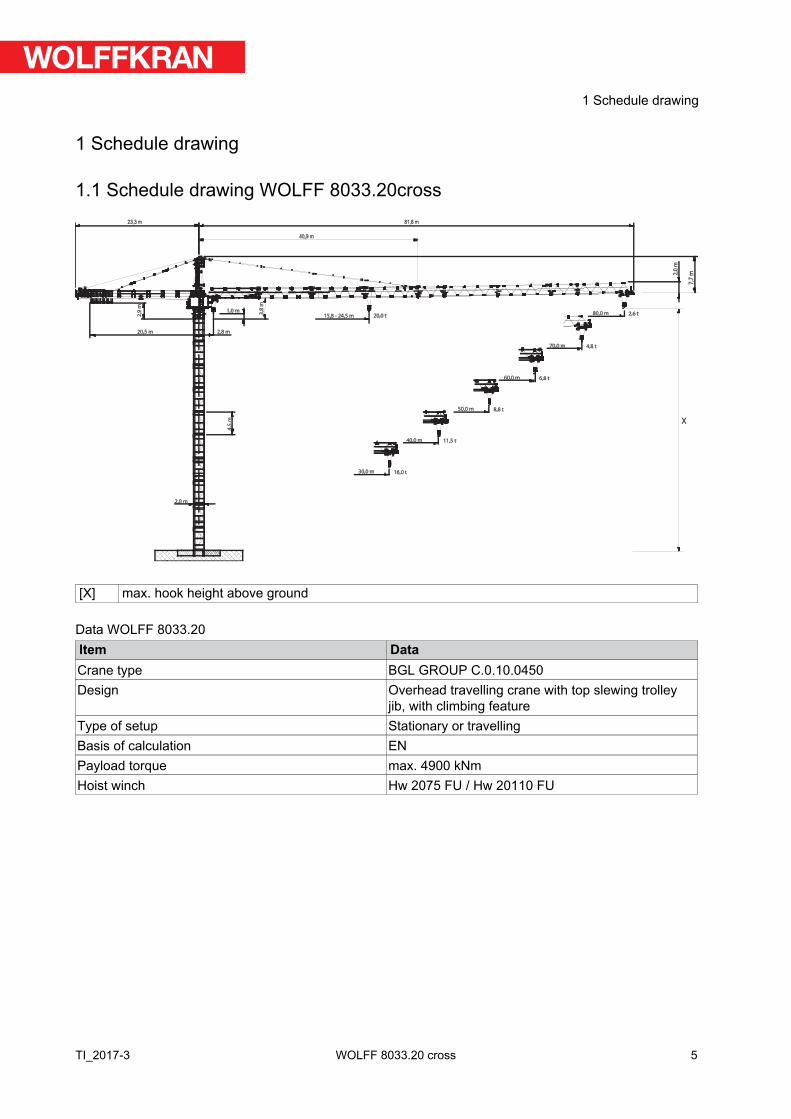
1 Schedule drawing
1.1 Schedule drawing WOLFF 8033.20cross
2,0
m
7,7
m
2,8 m
3,8
m
1,0 m
2,9
m
20,5 m
40,0 m
50,0 m
60,0 m
70,0 m
X
80,0 m
2,0 m
15,8 - 24,5 m 20,0 t
4,5
m
23,3 m 81,8 m
40,9 m
30,0 m 16,0 t
11,5 t
8,8 t
6,8 t
4,8 t
2,6 t
[X] max. hook height above ground
Data WOLFF 8033.20Item DataCrane type BGL GROUP C.0.10.0450Design Overhead travelling crane with top slewing trolley
jib, with climbing featureType of setup Stationary or travellingBasis of calculation ENPayload torque max. 4900 kNmHoist winch Hw 2075 FU / Hw 20110 FU
5
1 Schedule drawing
TI_2017-3 WOLFF 8033.20 cross
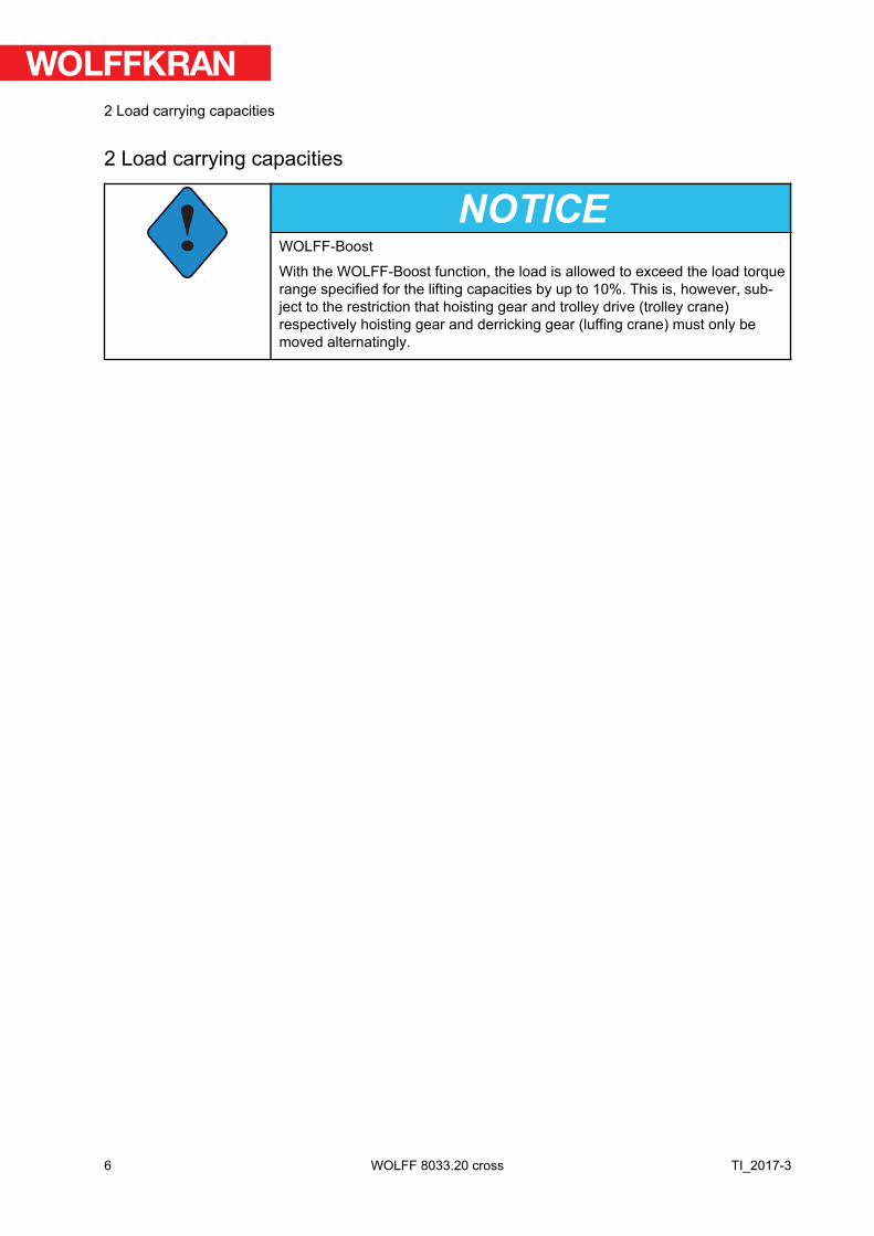
2 Load carrying capacities
!NOTICE
WOLFF-Boost
With the WOLFF-Boost function, the load is allowed to exceed the load torquerange specified for the lifting capacities by up to 10%. This is, however, sub-ject to the restriction that hoisting gear and trolley drive (trolley crane)respectively hoisting gear and derricking gear (luffing crane) must only bemoved alternatingly.
6
2 Load carrying capacities
TI_2017-3WOLFF 8033.20 cross
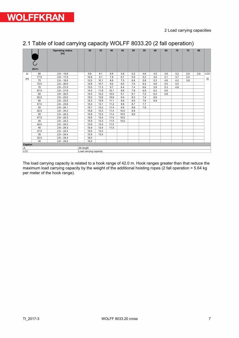
2.1 Table of load carrying capacity WOLFF 8033.20 (2 fall operation)
20.0 t
Operating radius[m]
30 35 40 45 50 55 60 65 70 75 80
JL
[m]
80 2.8 – 15.8 9.8 8.1 6.9 5.9 5.2 4.6 4.0 3.6 3.2 2.9 2.6 LCC
[t]77.5 2.8 – 17.5 10.9 9.1 7.8 6.7 5.9 5.2 4.6 4.1 3.7 3.475 2.8 – 19.0 12.0 10.1 8.6 7.5 6.6 5.8 5.2 4.6 4.2 3.8
72.5 2.8 – 20.0 12.8 10.7 9.2 8.0 7.0 6.2 5.6 5.0 4.570 2.8 – 21.0 13.5 11.3 9.7 8.4 7.4 6.6 5.9 5.3 4.8
67.5 2.8 – 21.8 14.0 11.8 10.1 8.8 7.8 6.9 6.2 5.665 2.8 – 22.5 14.5 12.2 10.5 9.1 8.1 7.2 6.4 5.8
62.5 2.8 – 23.0 15.0 12.6 10.8 9.4 8.3 7.4 6.660 2.8 – 23.5 15.3 12.9 11.1 9.6 8.5 7.6 6.8
57.5 2.8 – 23.8 15.5 13.1 11.2 9.8 8.7 7.755 2.8 – 24.1 15.7 13.2 11.4 9.9 8.8 7.8
52.5 2.8 – 24.2 15.8 13.3 11.4 10.0 8.850 2.8 – 24.2 15.8 13.3 11.4 10.0 8.8
47.5 2.8 – 24.3 15.9 13.4 11.5 10.045 2.8 – 24.3 15.9 13.3 11.5 10.0
42.5 2.8 – 24.3 15.9 13.4 11.540 2.8 – 24.3 15.9 13.4 11.5
37.5 2.8 – 24.4 15.9 13.435 2.8 – 24.4 15.9 13.4
32.5 2.8 – 24.4 16.030 2.8 – 24.5 16.0
CaptionJL Jib lengthLCC Load carrying capacity
The load carrying capacity is related to a hook range of 42.0 m. Hook ranges greater than that reduce themaximum load carrying capacity by the weight of the additional hoisting ropes (2 fall operation = 5.64 kgper meter of the hook range).
7
2 Load carrying capacities
TI_2017-3 WOLFF 8033.20 cross
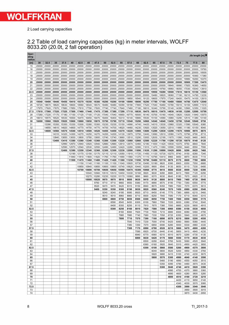
2.2 Table of load carrying capacities (kg) in meter intervals, WOLFF8033.20 (20.0t, 2 fall operation)Operatingradius
Jib length [m]
[m] 30 32.5 35 37.5 40 42.5 45 47.5 50 52.5 55 57.5 60 62.5 65 67.5 70 72.5 75 77.5 8015 20000 20000 20000 20000 20000 20000 20000 20000 20000 20000 20000 20000 20000 20000 20000 20000 20000 20000 20000 20000 2000016 20000 20000 20000 20000 20000 20000 20000 20000 20000 20000 20000 20000 20000 20000 20000 20000 20000 20000 20000 20000 1976017 20000 20000 20000 20000 20000 20000 20000 20000 20000 20000 20000 20000 20000 20000 20000 20000 20000 20000 20000 20000 1850018 20000 20000 20000 20000 20000 20000 20000 20000 20000 20000 20000 20000 20000 20000 20000 20000 20000 20000 20000 19360 1738019 20000 20000 20000 20000 20000 20000 20000 20000 20000 20000 20000 20000 20000 20000 20000 20000 20000 20000 19980 18260 1637020 20000 20000 20000 20000 20000 20000 20000 20000 20000 20000 20000 20000 20000 20000 20000 20000 20000 20000 18900 17260 1547021 20000 20000 20000 20000 20000 20000 20000 20000 20000 20000 20000 20000 20000 20000 20000 20000 19940 18990 17920 16360 1465022 20000 20000 20000 20000 20000 20000 20000 20000 20000 20000 20000 20000 20000 20000 20000 19760 18960 18050 17030 15540 13910
22.5 20000 20000 20000 20000 20000 20000 20000 20000 20000 20000 20000 20000 20000 20000 19950 19280 18500 17610 16610 15150 1356023 20000 20000 20000 20000 20000 20000 20000 20000 20000 20000 20000 20000 20000 20000 19480 18820 18060 17190 16210 14790 1323024 20000 20000 20000 20000 20000 20000 20000 20000 20000 20000 20000 19850 19540 19120 18600 17970 17240 16400 15470 14100 1261025 19540 19490 19440 19450 19410 19370 19350 19380 19290 19290 19190 18990 18690 18290 17780 17180 16480 15680 14780 13470 1204026 18720 18670 18620 18630 18600 18560 18540 18570 18480 18480 18390 18190 17900 17520 17040 16460 15780 15010 14150 12890 1151027 17970 17920 17870 17880 17850 17810 17790 17820 17740 17740 17640 17460 17180 16810 16340 15790 15140 14390 13560 12350 11020
27.5 17610 17560 17520 17520 17500 17460 17440 17470 17380 17380 17290 17110 16830 16470 16010 15470 14830 14100 13280 12090 1079028 17260 17220 17170 17180 17150 17120 17100 17120 17040 17040 16950 16770 16500 16140 15700 15160 14540 13820 13020 11840 1057029 16610 16570 16520 16530 16500 16470 16450 16470 16400 16400 16310 16140 15880 15530 15100 14580 13980 13290 12510 11380 1014030 16000 15960 15920 15920 15900 15860 15850 15870 15790 15790 15710 15540 15290 14960 14540 14040 13450 12790 12040 10940 975031 15390 15350 15350 15330 15300 15280 15300 15230 15230 15150 14990 14740 14420 14010 13530 12960 12320 11590 10540 938032 14850 14810 14820 14800 14770 14750 14770 14700 14700 14620 14460 14230 13920 13520 13050 12510 11880 11180 10150 9040
32.5 14600 14560 14570 14540 14510 14500 14520 14450 14450 14370 14220 13980 13680 13290 12830 12290 11670 10980 9970 887033 14310 14320 14300 14270 14250 14270 14200 14200 14130 13970 13750 13440 13060 12610 12080 11470 10790 9790 871034 13840 13850 13830 13800 13780 13800 13740 13740 13660 13510 13290 13000 12630 12190 11670 11080 10420 9460 840035 13400 13410 13380 13360 13340 13360 13300 13300 13220 13080 12860 12580 12220 11790 11290 10720 10070 9140 812036 12990 12970 12940 12920 12940 12880 12880 12810 12670 12460 12180 11830 11420 10930 10370 9750 8840 784037 12590 12570 12540 12530 12550 12490 12490 12420 12280 12080 11810 11470 11060 10590 10050 9440 8550 7590
37.5 12400 12380 12350 12340 12360 12300 12300 12230 12090 11890 11630 11290 10890 10420 9890 9290 8420 746038 12190 12170 12150 12170 12110 12110 12050 11910 11720 11450 11120 10730 10270 9740 9150 8280 734039 11840 11810 11800 11820 11760 11760 11690 11560 11370 11110 10790 10410 9960 9450 8870 8030 711040 11500 11470 11460 11480 11420 11420 11360 11230 11050 10790 10480 10110 9670 9170 8600 7780 689041 11150 11140 11160 11100 11100 11040 10920 10730 10490 10180 9820 9390 8900 8350 7550 668042 10850 10840 10850 10800 10800 10740 10620 10440 10200 9900 9540 9130 8650 8110 7330 6480
42.5 10700 10690 10700 10650 10650 10590 10470 10300 10060 9770 9410 9000 8530 8000 7230 639043 10540 10560 10510 10510 10450 10330 10160 9920 9630 9280 8880 8410 7890 7120 629044 10270 10280 10230 10230 10170 10060 9890 9660 9370 9030 8640 8180 7670 6920 611045 10000 10020 9970 9970 9910 9800 9630 9410 9130 8800 8410 7960 7460 6730 594046 9760 9710 9710 9660 9550 9380 9170 8890 8570 8190 7750 7260 6550 577047 9520 9470 9470 9420 9310 9150 8940 8670 8350 7980 7550 7070 6370 5610
47.5 9400 9350 9350 9300 9190 9030 8820 8560 8240 7870 7450 6980 6290 554048 9240 9240 9180 9080 8920 8710 8450 8140 7770 7360 6890 6210 546049 9010 9010 8960 8860 8710 8500 8250 7940 7580 7170 6710 6040 531050 8800 8800 8750 8650 8500 8300 8050 7750 7400 7000 6550 5890 517051 8590 8540 8450 8300 8100 7860 7560 7220 6830 6380 5740 504052 8400 8350 8250 8110 7910 7670 7380 7050 6660 6230 5600 4910
52.5 8300 8250 8160 8010 7820 7580 7300 6960 6580 6150 5530 485053 8160 8060 7920 7730 7500 7210 6880 6500 6080 5460 479054 7980 7880 7740 7560 7330 7050 6720 6350 5940 5330 467055 7800 7710 7570 7390 7160 6890 6570 6210 5800 5200 455056 7540 7410 7230 7000 6740 6420 6060 5660 5080 444057 7380 7250 7070 6850 6590 6280 5930 5530 4960 4330
57.5 7300 7170 6990 6780 6520 6210 5860 5470 4900 428058 7090 6920 6700 6440 6140 5800 5410 4840 423059 6940 6770 6560 6310 6010 5670 5290 4730 413060 6800 6630 6420 6170 5880 5550 5170 4630 403061 6500 6290 6040 5760 5430 5060 4520 394062 6360 6160 5920 5640 5310 4950 4420 3850
62.5 6300 6100 5860 5580 5260 4900 4370 380063 6040 5800 5520 5200 4850 4330 376064 5920 5680 5410 5100 4740 4230 367065 5800 5570 5300 4990 4640 4140 359066 5460 5190 4890 4550 4050 351067 5350 5090 4790 4460 3970 3430
67.5 5300 5040 4740 4410 3920 339068 4990 4700 4370 3880 336069 4890 4600 4280 3800 328070 4800 4510 4190 3720 321071 4430 4110 3650 314072 4340 4030 3570 3080
72.5 4300 3990 3540 304073 3950 3500 301074 3870 3430 2950
8
2 Load carrying capacities
TI_2017-3WOLFF 8033.20 cross
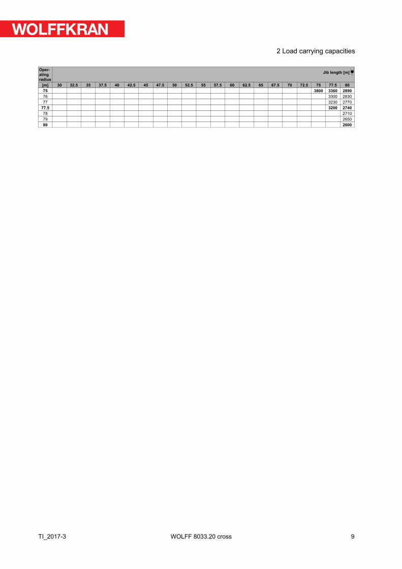
Operatingradius
Jib length [m]
[m] 30 32.5 35 37.5 40 42.5 45 47.5 50 52.5 55 57.5 60 62.5 65 67.5 70 72.5 75 77.5 8075 3800 3360 289076 3300 283077 3230 2770
77.5 3200 274078 271079 265080 2600
9
2 Load carrying capacities
TI_2017-3 WOLFF 8033.20 cross
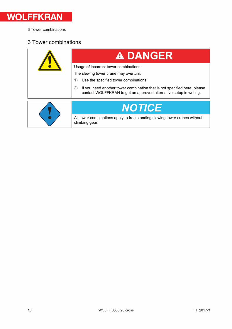
3 Tower combinations
DANGERUsage of incorrect tower combinations.
The slewing tower crane may overturn.
1) Use the specified tower combinations.
2) If you need another tower combination that is not specified here, pleasecontact WOLFFKRAN to get an approved alternative setup in writing.
!NOTICE
All tower combinations apply to free standing slewing tower cranes withoutclimbing gear.
10
3 Tower combinations
TI_2017-3WOLFF 8033.20 cross
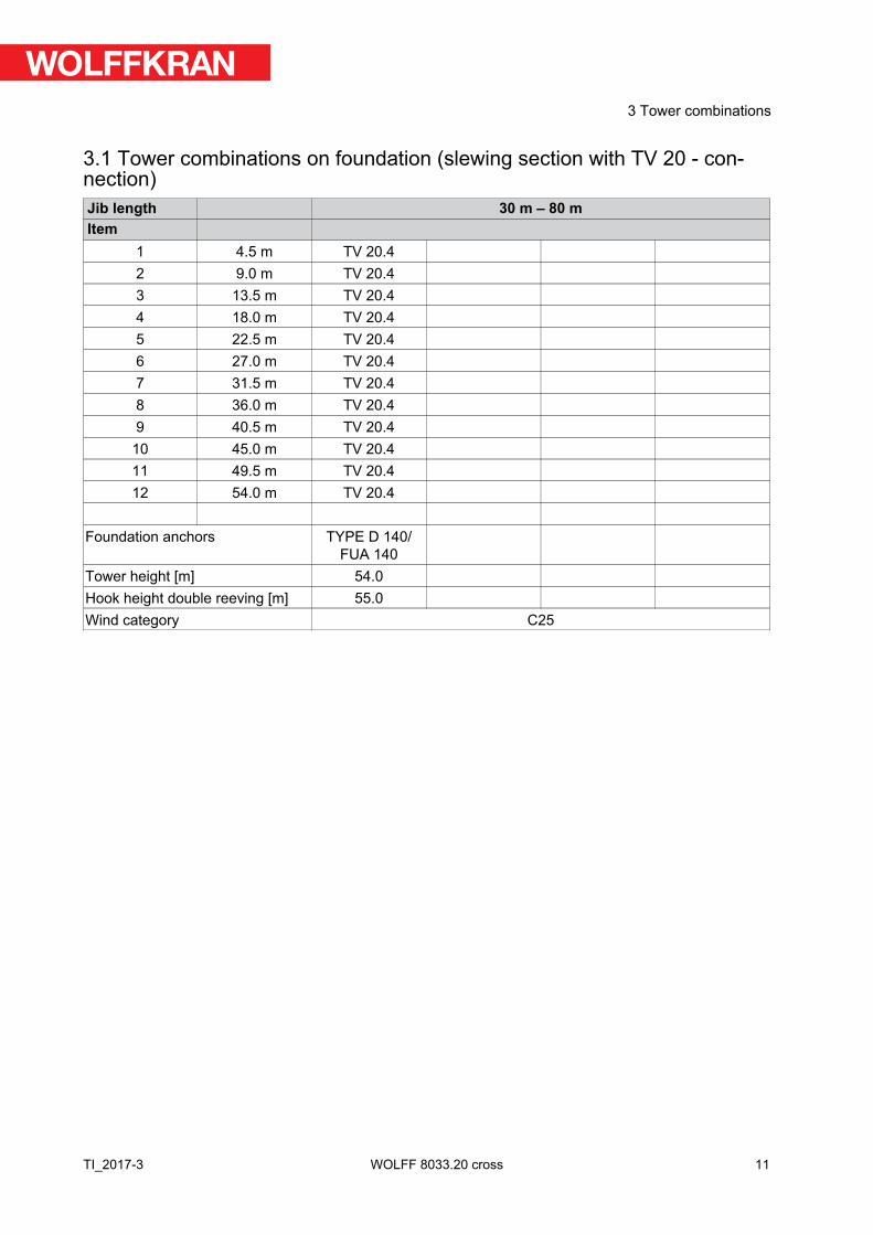
3.1 Tower combinations on foundation (slewing section with TV 20 - con-nection)Jib length 30 m – 80 mItem
1 4.5 m TV 20.42 9.0 m TV 20.43 13.5 m TV 20.44 18.0 m TV 20.45 22.5 m TV 20.46 27.0 m TV 20.47 31.5 m TV 20.48 36.0 m TV 20.49 40.5 m TV 20.4
10 45.0 m TV 20.411 49.5 m TV 20.412 54.0 m TV 20.4
Foundation anchors TYPE D 140/FUA 140
Tower height [m] 54.0Hook height double reeving [m] 55.0Wind category C25
11
3 Tower combinations
TI_2017-3 WOLFF 8033.20 cross
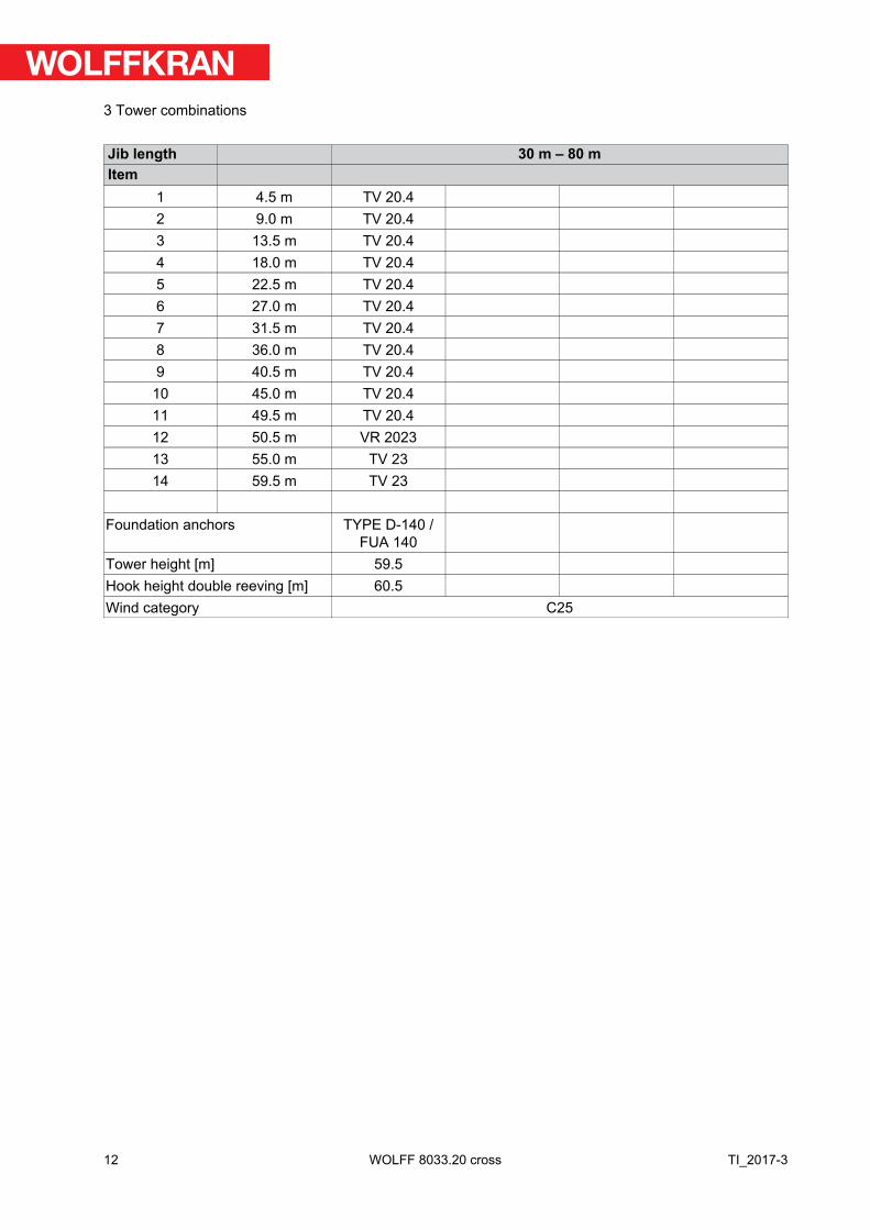
Jib length 30 m – 80 mItem
1 4.5 m TV 20.42 9.0 m TV 20.43 13.5 m TV 20.44 18.0 m TV 20.45 22.5 m TV 20.46 27.0 m TV 20.47 31.5 m TV 20.48 36.0 m TV 20.49 40.5 m TV 20.4
10 45.0 m TV 20.411 49.5 m TV 20.412 50.5 m VR 202313 55.0 m TV 2314 59.5 m TV 23
Foundation anchors TYPE D-140 /FUA 140
Tower height [m] 59.5Hook height double reeving [m] 60.5Wind category C25
12
3 Tower combinations
TI_2017-3WOLFF 8033.20 cross
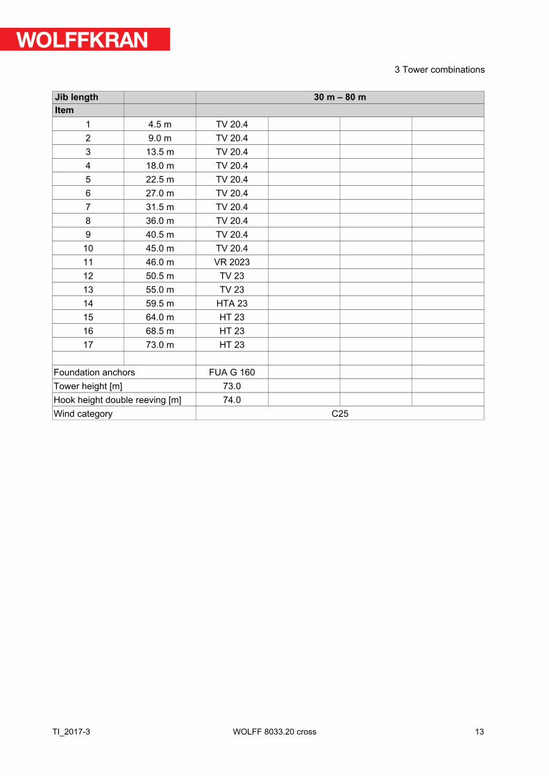
Jib length 30 m – 80 mItem
1 4.5 m TV 20.42 9.0 m TV 20.43 13.5 m TV 20.44 18.0 m TV 20.45 22.5 m TV 20.46 27.0 m TV 20.47 31.5 m TV 20.48 36.0 m TV 20.49 40.5 m TV 20.4
10 45.0 m TV 20.411 46.0 m VR 202312 50.5 m TV 2313 55.0 m TV 2314 59.5 m HTA 2315 64.0 m HT 2316 68.5 m HT 2317 73.0 m HT 23
Foundation anchors FUA G 160Tower height [m] 73.0Hook height double reeving [m] 74.0Wind category C25
13
3 Tower combinations
TI_2017-3 WOLFF 8033.20 cross
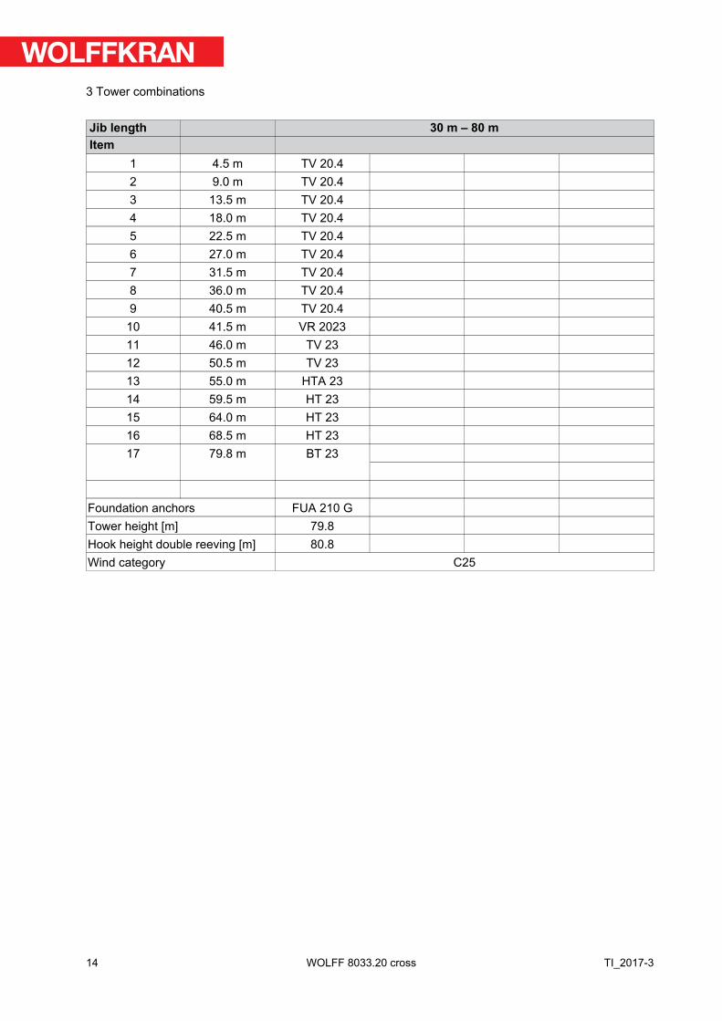
Jib length 30 m – 80 mItem
1 4.5 m TV 20.42 9.0 m TV 20.43 13.5 m TV 20.44 18.0 m TV 20.45 22.5 m TV 20.46 27.0 m TV 20.47 31.5 m TV 20.48 36.0 m TV 20.49 40.5 m TV 20.4
10 41.5 m VR 202311 46.0 m TV 2312 50.5 m TV 2313 55.0 m HTA 2314 59.5 m HT 2315 64.0 m HT 2316 68.5 m HT 2317 79.8 m BT 23
Foundation anchors FUA 210 GTower height [m] 79.8Hook height double reeving [m] 80.8Wind category C25
14
3 Tower combinations
TI_2017-3WOLFF 8033.20 cross
Jib length 30 m – 80 mItem
1 4.5 m TV 20.42 9.0 m TV 20.43 13.5 m TV 20.44 18.0 m TV 20.45 22.5 m TV 20.46 27.0 m TV 20.47 31.5 m TV 20.48 36.0 m TV 20.49 40.5 m TV 20.4
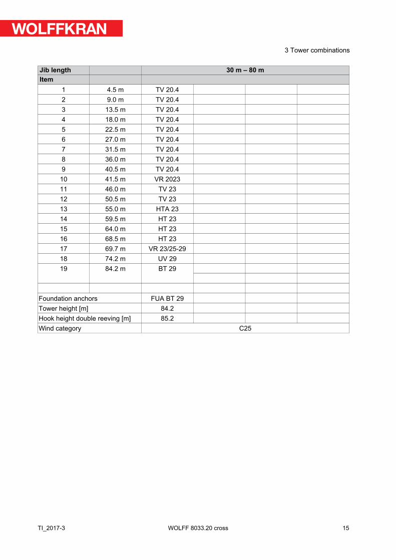
10 41.5 m VR 202311 46.0 m TV 2312 50.5 m TV 2313 55.0 m HTA 2314 59.5 m HT 2315 64.0 m HT 2316 68.5 m HT 2317 69.7 m VR 23/25-2918 74.2 m UV 2919 84.2 m BT 29
Foundation anchors FUA BT 29Tower height [m] 84.2Hook height double reeving [m] 85.2Wind category C25
15
3 Tower combinations
TI_2017-3 WOLFF 8033.20 cross
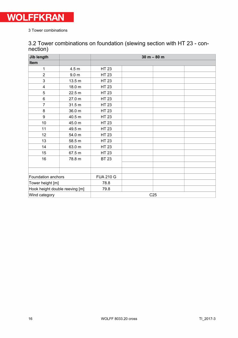
3.2 Tower combinations on foundation (slewing section with HT 23 - con-nection)Jib length 30 m – 80 mItem
1 4.5 m HT 232 9.0 m HT 233 13.5 m HT 234 18.0 m HT 235 22.5 m HT 236 27.0 m HT 237 31.5 m HT 238 36.0 m HT 239 40.5 m HT 23
10 45.0 m HT 2311 49.5 m HT 2312 54.0 m HT 2313 58.5 m HT 2314 63.0 m HT 2315 67.5 m HT 2316 78.8 m BT 23
Foundation anchors FUA 210 GTower height [m] 78.8Hook height double reeving [m] 79.8Wind category C25
16
3 Tower combinations
TI_2017-3WOLFF 8033.20 cross
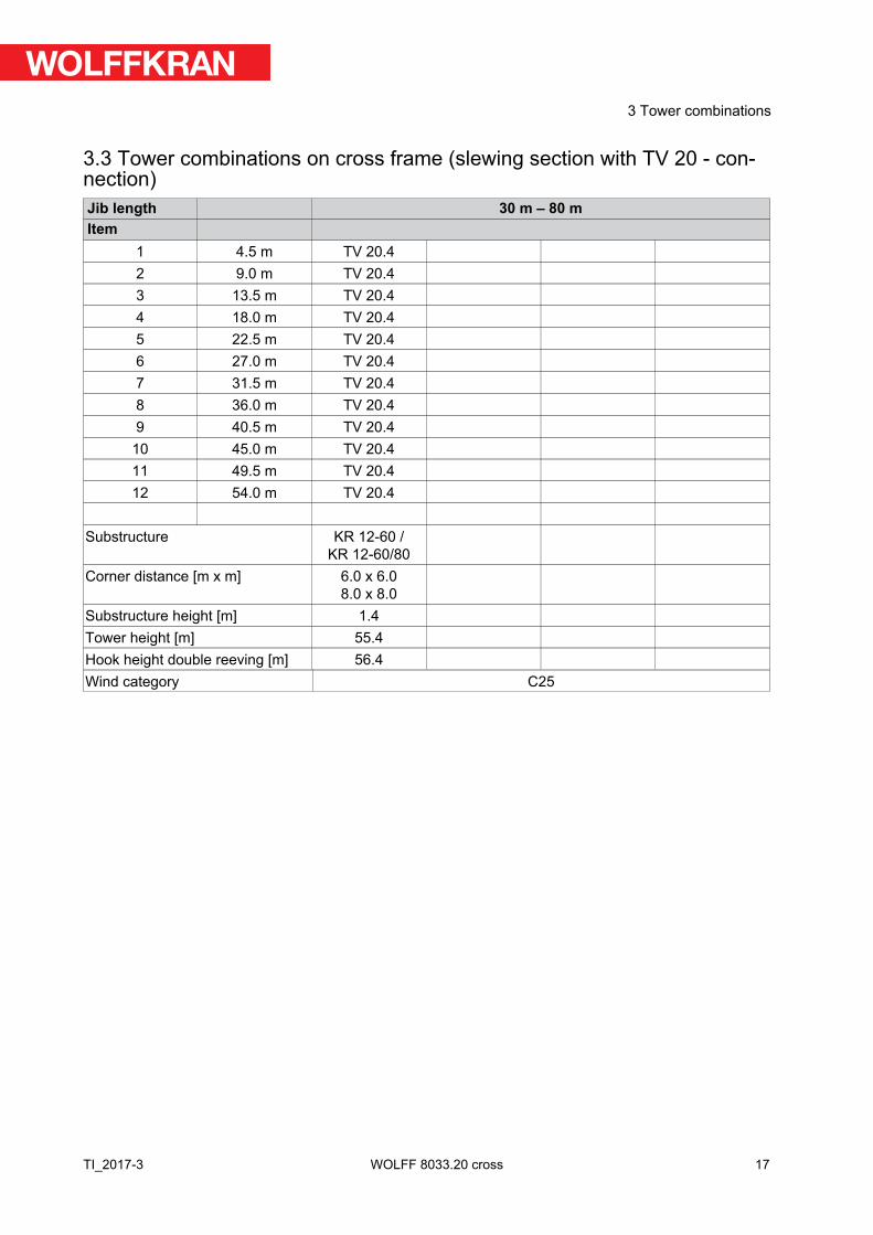
3.3 Tower combinations on cross frame (slewing section with TV 20 - con-nection)Jib length 30 m – 80 mItem
1 4.5 m TV 20.42 9.0 m TV 20.43 13.5 m TV 20.44 18.0 m TV 20.45 22.5 m TV 20.46 27.0 m TV 20.47 31.5 m TV 20.48 36.0 m TV 20.49 40.5 m TV 20.4
10 45.0 m TV 20.411 49.5 m TV 20.412 54.0 m TV 20.4
Substructure KR 12-60 /
KR 12-60/80Corner distance [m x m] 6.0 x 6.0
8.0 x 8.0Substructure height [m] 1.4Tower height [m] 55.4Hook height double reeving [m] 56.4Wind category C25
17
3 Tower combinations
TI_2017-3 WOLFF 8033.20 cross
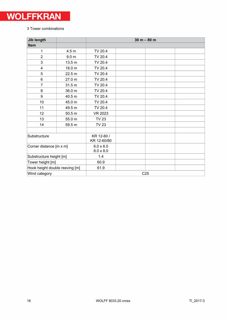
Jib length 30 m – 80 mItem
1 4.5 m TV 20.42 9.0 m TV 20.43 13.5 m TV 20.44 18.0 m TV 20.45 22.5 m TV 20.46 27.0 m TV 20.47 31.5 m TV 20.48 36.0 m TV 20.49 40.5 m TV 20.4
10 45.0 m TV 20.411 49.5 m TV 20.412 50.5 m VR 202313 55.0 m TV 2314 59.5 m TV 23
Substructure KR 12-60 /KR 12-60/80
Corner distance [m x m] 6.0 x 6.08.0 x 8.0
Substructure height [m] 1.4Tower height [m] 60.9Hook height double reeving [m] 61.9Wind category C25
18
3 Tower combinations
TI_2017-3WOLFF 8033.20 cross
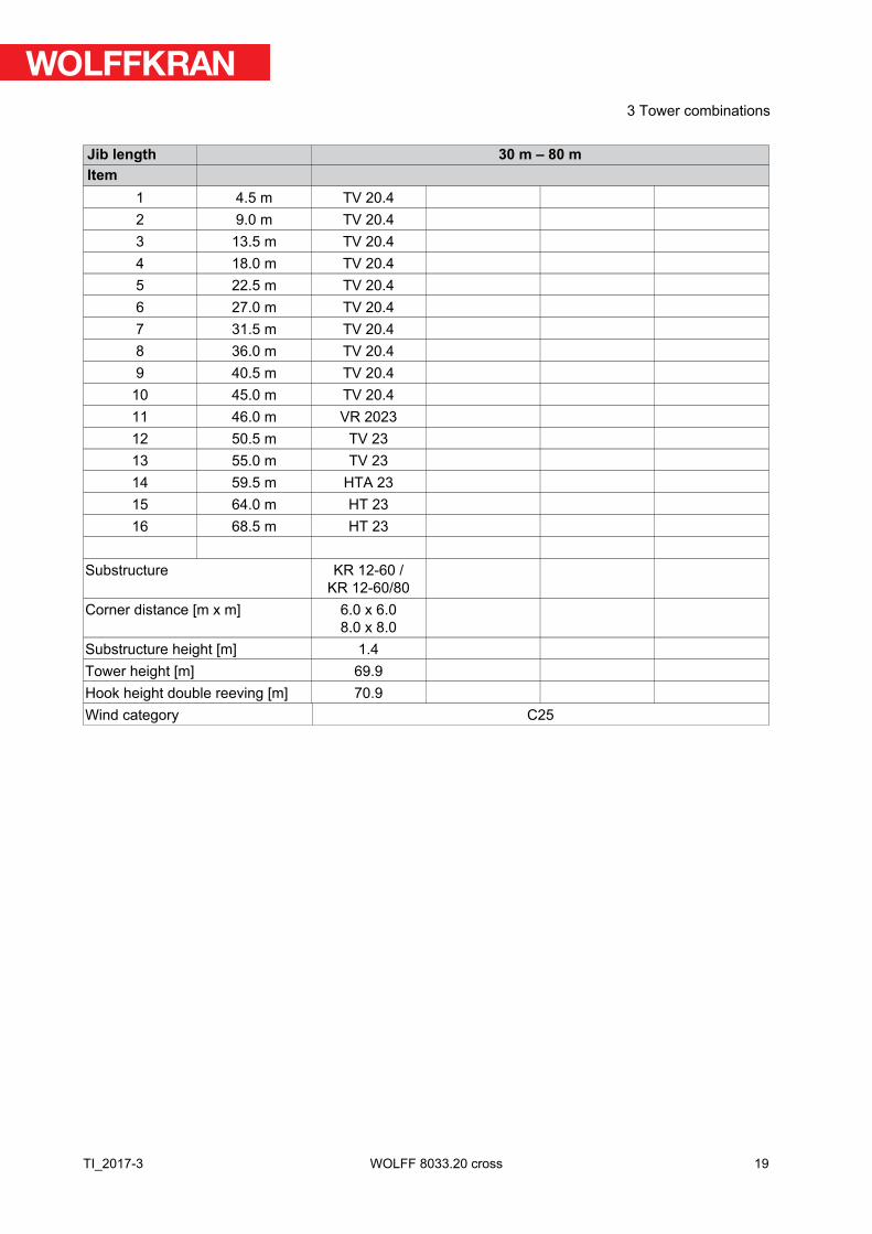
Jib length 30 m – 80 mItem
1 4.5 m TV 20.42 9.0 m TV 20.43 13.5 m TV 20.44 18.0 m TV 20.45 22.5 m TV 20.46 27.0 m TV 20.47 31.5 m TV 20.48 36.0 m TV 20.49 40.5 m TV 20.4
10 45.0 m TV 20.411 46.0 m VR 202312 50.5 m TV 2313 55.0 m TV 2314 59.5 m HTA 2315 64.0 m HT 2316 68.5 m HT 23
Substructure KR 12-60 /KR 12-60/80
Corner distance [m x m] 6.0 x 6.08.0 x 8.0
Substructure height [m] 1.4Tower height [m] 69.9Hook height double reeving [m] 70.9Wind category C25
19
3 Tower combinations
TI_2017-3 WOLFF 8033.20 cross
Jib length 30 m – 80 mItem
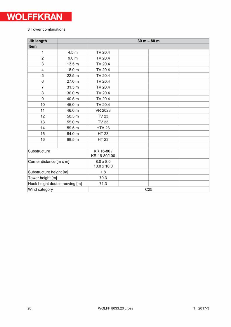
1 4.5 m TV 20.42 9.0 m TV 20.43 13.5 m TV 20.44 18.0 m TV 20.45 22.5 m TV 20.46 27.0 m TV 20.47 31.5 m TV 20.48 36.0 m TV 20.49 40.5 m TV 20.4
10 45.0 m TV 20.411 46.0 m VR 202312 50.5 m TV 2313 55.0 m TV 2314 59.5 m HTA 2315 64.0 m HT 2316 68.5 m HT 23
Substructure KR 16-80 /KR 16-80/100
Corner distance [m x m] 8.0 x 8.010.0 x 10.0
Substructure height [m] 1.8Tower height [m] 70.3Hook height double reeving [m] 71.3Wind category C25
20
3 Tower combinations
TI_2017-3WOLFF 8033.20 cross
Jib length 30 m – 80 mItem
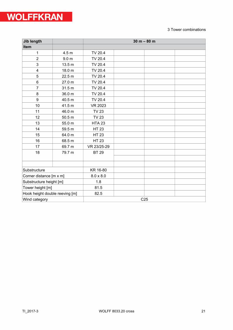
1 4.5 m TV 20.42 9.0 m TV 20.43 13.5 m TV 20.44 18.0 m TV 20.45 22.5 m TV 20.46 27.0 m TV 20.47 31.5 m TV 20.48 36.0 m TV 20.49 40.5 m TV 20.4
10 41.5 m VR 202311 46.0 m TV 2312 50.5 m TV 2313 55.0 m HTA 2314 59.5 m HT 2315 64.0 m HT 2316 68.5 m HT 2317 69.7 m VR 23/25-2918 79.7 m BT 29
Substructure KR 16-80Corner distance [m x m] 8.0 x 8.0Substructure height [m] 1.8Tower height [m] 81.5Hook height double reeving [m] 82.5Wind category C25
21
3 Tower combinations
TI_2017-3 WOLFF 8033.20 cross
Jib length 30 m – 80 mItem
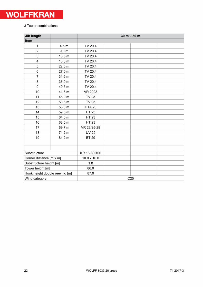
1 4.5 m TV 20.42 9.0 m TV 20.43 13.5 m TV 20.44 18.0 m TV 20.45 22.5 m TV 20.46 27.0 m TV 20.47 31.5 m TV 20.48 36.0 m TV 20.49 40.5 m TV 20.4
10 41.5 m VR 202311 46.0 m TV 2312 50.5 m TV 2313 55.0 m HTA 2314 59.5 m HT 2315 64.0 m HT 2316 68.5 m HT 2317 69.7 m VR 23/25-2918 74.2 m UV 2919 84.2 m BT 29
Substructure KR 16-80/100Corner distance [m x m] 10.0 x 10.0Substructure height [m] 1.8Tower height [m] 86.0Hook height double reeving [m] 87.0Wind category C25
22
3 Tower combinations
TI_2017-3WOLFF 8033.20 cross
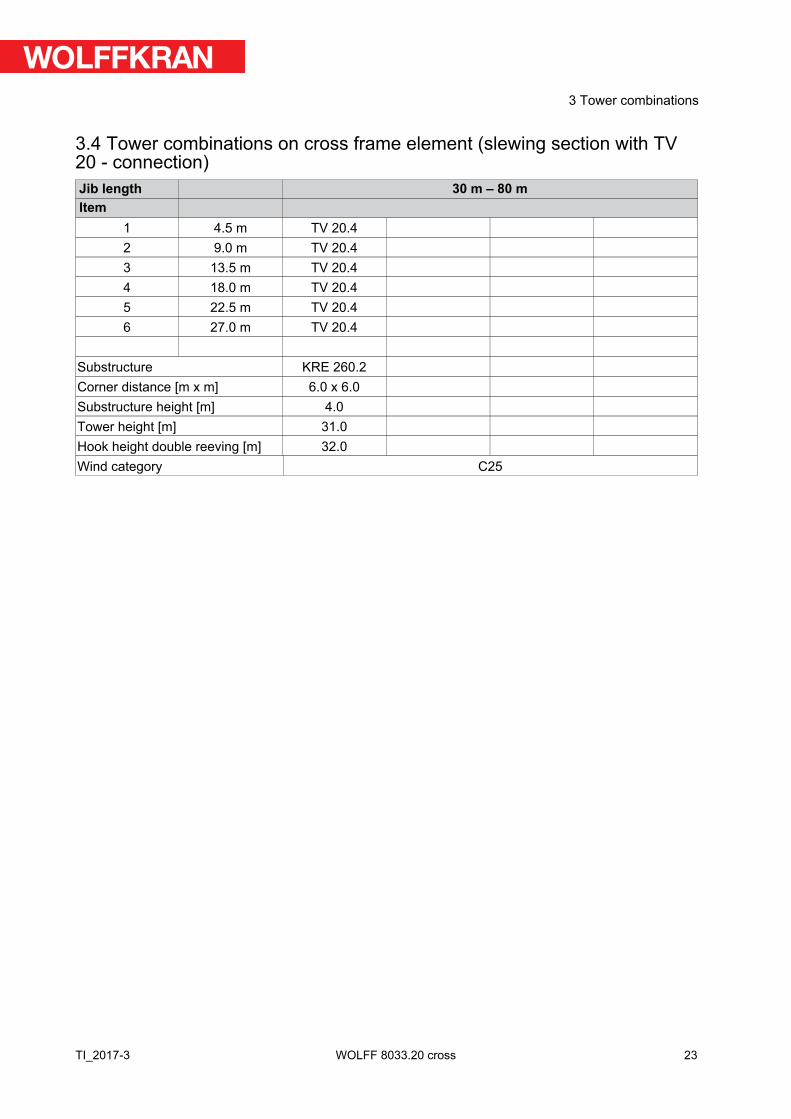
3.4 Tower combinations on cross frame element (slewing section with TV20 - connection)Jib length 30 m – 80 mItem
1 4.5 m TV 20.42 9.0 m TV 20.43 13.5 m TV 20.44 18.0 m TV 20.45 22.5 m TV 20.46 27.0 m TV 20.4
Substructure KRE 260.2Corner distance [m x m] 6.0 x 6.0Substructure height [m] 4.0Tower height [m] 31.0Hook height double reeving [m] 32.0Wind category C25
23
3 Tower combinations
TI_2017-3 WOLFF 8033.20 cross
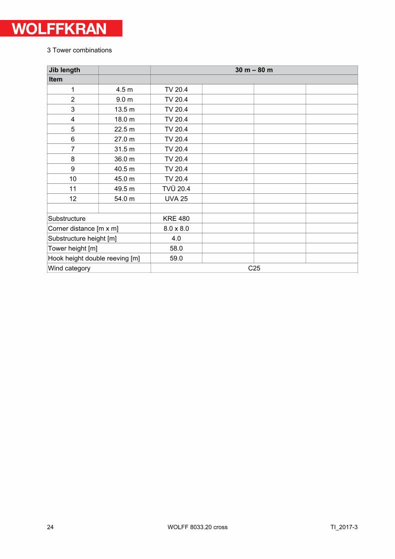
Jib length 30 m – 80 mItem
1 4.5 m TV 20.42 9.0 m TV 20.43 13.5 m TV 20.44 18.0 m TV 20.45 22.5 m TV 20.46 27.0 m TV 20.47 31.5 m TV 20.48 36.0 m TV 20.49 40.5 m TV 20.4
10 45.0 m TV 20.411 49.5 m TVÜ 20.412 54.0 m UVA 25
Substructure KRE 480Corner distance [m x m] 8.0 x 8.0Substructure height [m] 4.0Tower height [m] 58.0Hook height double reeving [m] 59.0Wind category C25
24
3 Tower combinations
TI_2017-3WOLFF 8033.20 cross
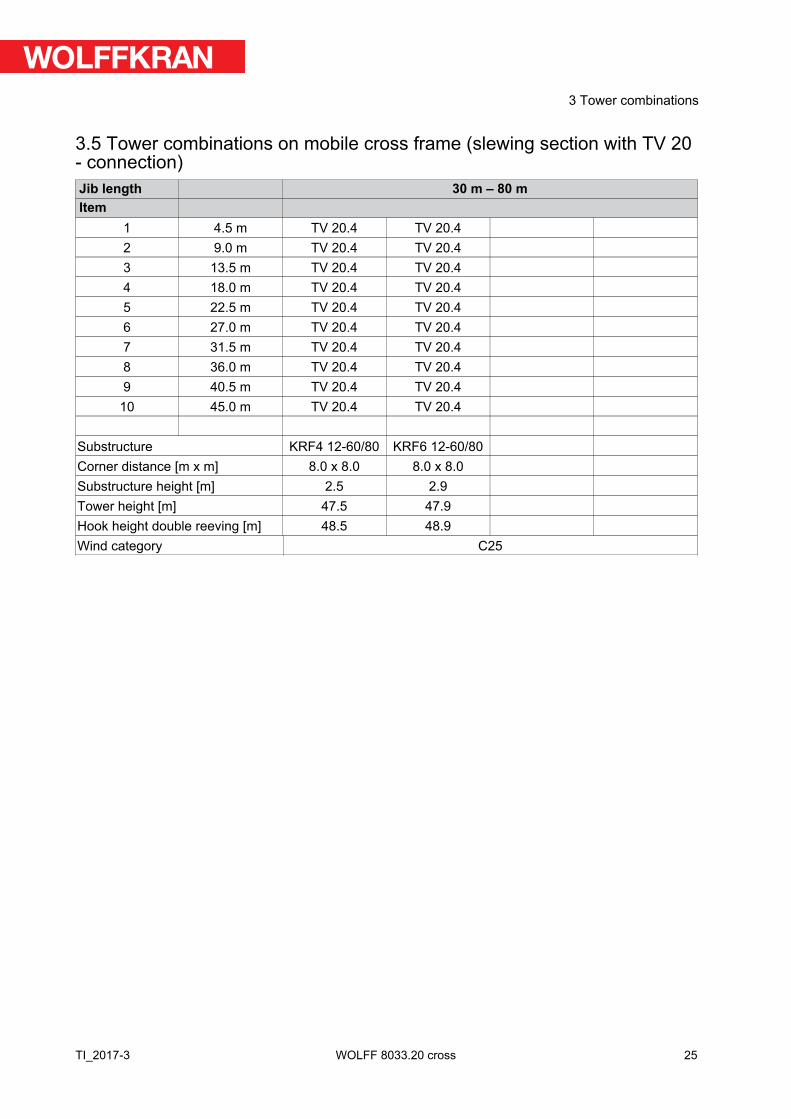
3.5 Tower combinations on mobile cross frame (slewing section with TV 20- connection)Jib length 30 m – 80 mItem
1 4.5 m TV 20.4 TV 20.42 9.0 m TV 20.4 TV 20.43 13.5 m TV 20.4 TV 20.44 18.0 m TV 20.4 TV 20.45 22.5 m TV 20.4 TV 20.46 27.0 m TV 20.4 TV 20.47 31.5 m TV 20.4 TV 20.48 36.0 m TV 20.4 TV 20.49 40.5 m TV 20.4 TV 20.4
10 45.0 m TV 20.4 TV 20.4
Substructure KRF4 12-60/80 KRF6 12-60/80Corner distance [m x m] 8.0 x 8.0 8.0 x 8.0Substructure height [m] 2.5 2.9Tower height [m] 47.5 47.9Hook height double reeving [m] 48.5 48.9Wind category C25
25
3 Tower combinations
TI_2017-3 WOLFF 8033.20 cross
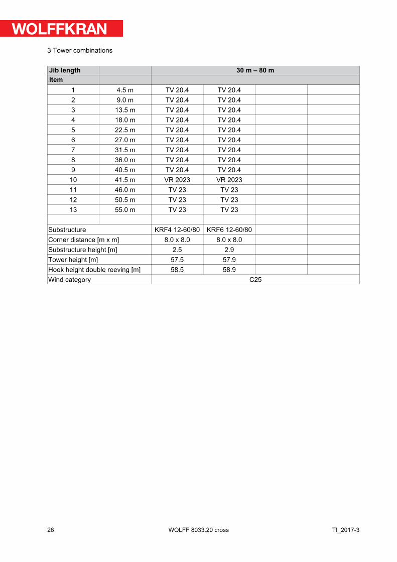
Jib length 30 m – 80 mItem
1 4.5 m TV 20.4 TV 20.42 9.0 m TV 20.4 TV 20.43 13.5 m TV 20.4 TV 20.44 18.0 m TV 20.4 TV 20.45 22.5 m TV 20.4 TV 20.46 27.0 m TV 20.4 TV 20.47 31.5 m TV 20.4 TV 20.48 36.0 m TV 20.4 TV 20.49 40.5 m TV 20.4 TV 20.4
10 41.5 m VR 2023 VR 202311 46.0 m TV 23 TV 2312 50.5 m TV 23 TV 2313 55.0 m TV 23 TV 23
Substructure KRF4 12-60/80 KRF6 12-60/80Corner distance [m x m] 8.0 x 8.0 8.0 x 8.0Substructure height [m] 2.5 2.9Tower height [m] 57.5 57.9Hook height double reeving [m] 58.5 58.9Wind category C25
26
3 Tower combinations
TI_2017-3WOLFF 8033.20 cross
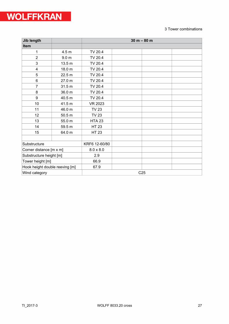
Jib length 30 m – 80 mItem
1 4.5 m TV 20.42 9.0 m TV 20.43 13.5 m TV 20.44 18.0 m TV 20.45 22.5 m TV 20.46 27.0 m TV 20.47 31.5 m TV 20.48 36.0 m TV 20.49 40.5 m TV 20.4
10 41.5 m VR 202311 46.0 m TV 2312 50.5 m TV 2313 55.0 m HTA 2314 59.5 m HT 2315 64.0 m HT 23
Substructure KRF6 12-60/80Corner distance [m x m] 8.0 x 8.0Substructure height [m] 2.9Tower height [m] 66.9Hook height double reeving [m] 67.9Wind category C25
27
3 Tower combinations
TI_2017-3 WOLFF 8033.20 cross
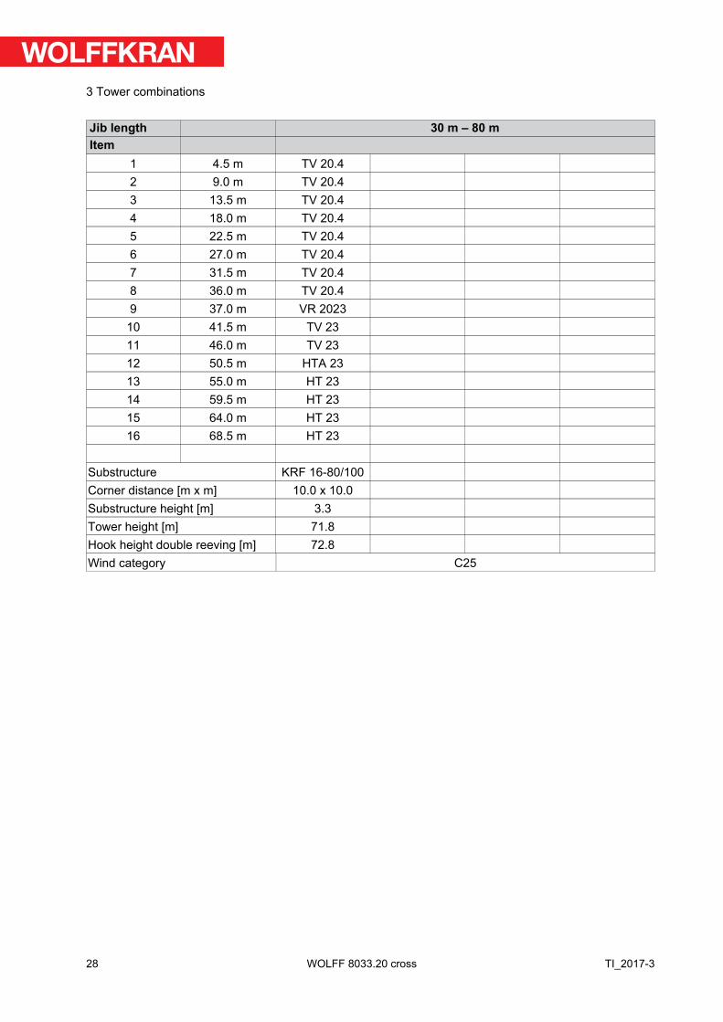
Jib length 30 m – 80 mItem
1 4.5 m TV 20.42 9.0 m TV 20.43 13.5 m TV 20.44 18.0 m TV 20.45 22.5 m TV 20.46 27.0 m TV 20.47 31.5 m TV 20.48 36.0 m TV 20.49 37.0 m VR 2023
10 41.5 m TV 2311 46.0 m TV 2312 50.5 m HTA 2313 55.0 m HT 2314 59.5 m HT 2315 64.0 m HT 2316 68.5 m HT 23
Substructure KRF 16-80/100Corner distance [m x m] 10.0 x 10.0Substructure height [m] 3.3Tower height [m] 71.8Hook height double reeving [m] 72.8Wind category C25
28
3 Tower combinations
TI_2017-3WOLFF 8033.20 cross
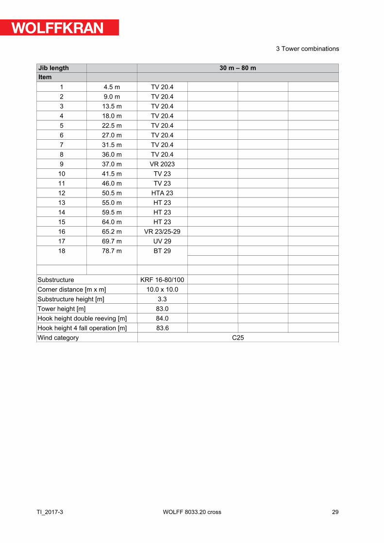
Jib length 30 m – 80 mItem
1 4.5 m TV 20.42 9.0 m TV 20.43 13.5 m TV 20.44 18.0 m TV 20.45 22.5 m TV 20.46 27.0 m TV 20.47 31.5 m TV 20.48 36.0 m TV 20.49 37.0 m VR 2023
10 41.5 m TV 2311 46.0 m TV 2312 50.5 m HTA 2313 55.0 m HT 2314 59.5 m HT 2315 64.0 m HT 2316 65.2 m VR 23/25-2917 69.7 m UV 2918 78.7 m BT 29
Substructure KRF 16-80/100Corner distance [m x m] 10.0 x 10.0Substructure height [m] 3.3Tower height [m] 83.0Hook height double reeving [m] 84.0Hook height 4 fall operation [m] 83.6Wind category C25
29
3 Tower combinations
TI_2017-3 WOLFF 8033.20 cross
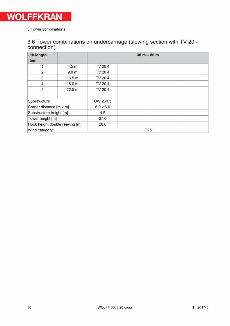
3.6 Tower combinations on undercarriage (slewing section with TV 20 -connection)Jib length 30 m – 80 mItem
1 4.5 m TV 20.42 9.0 m TV 20.43 13.5 m TV 20.44 18.0 m TV 20.45 22.5 m TV 20.4
Substructure UW 260.3Corner distance [m x m] 6.0 x 6.0Substructure height [m] 4.5Tower height [m] 27.0Hook height double reeving [m] 28.0Wind category C25
30
3 Tower combinations
TI_2017-3WOLFF 8033.20 cross

Jib length 30 m – 80 mItem
1 4.5 m TV 20.42 9.0 m TV 20.43 13.5 m TV 20.44 18.0 m TV 20.45 22.5 m TV 20.46 27.0 m TV 20.47 31.5 m TV 20.48 36.0 m TV 20.49 40.5 m TV 20.4
10 45.0 m TVÜ 20.411 49.5 m TV 2512 54.0 m UVA 25
Substructure UW 480Corner distance [m x m] 8.0 x 8.0Substructure height [m] 5.0Tower height [m] 59.0Hook height double reeving [m] 60.0Wind category C25
31
3 Tower combinations
TI_2017-3 WOLFF 8033.20 cross
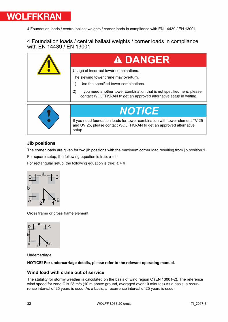
4 Foundation loads / central ballast weights / corner loads in compliancewith EN 14439 / EN 13001
DANGERUsage of incorrect tower combinations.
The slewing tower crane may overturn.
1) Use the specified tower combinations.
2) If you need another tower combination that is not specified here, pleasecontact WOLFFKRAN to get an approved alternative setup in writing.
!NOTICE
If you need foundation loads for tower combination with tower element TV 25and UV 25, please contact WOLFFKRAN to get an approved alternativesetup.
Jib positionsThe corner loads are given for two jib positions with the maximum corner load resulting from jib position 1.
For square setup, the following equation is true: a = b
For rectangular setup, the following equation is true: a > b
A B1
D Ca
b
2
Cross frame or cross frame element
A B1
D C
2
a
b
Undercarriage
NOTICE! For undercarriage details, please refer to the relevant operating manual.
Wind load with crane out of serviceThe stability for stormy weather is calculated on the basis of wind region C (EN 13001-2). The referencewind speed for zone C is 28 m/s (10 m above ground, averaged over 10 minutes).As a basis, a recur-rence interval of 25 years is used. As a basis, a recurrence interval of 25 years is used.
32
4 Foundation loads / central ballast weights / corner loads in compliance with EN 14439 / EN 13001
TI_2017-3WOLFF 8033.20 cross
Please contact WOLFFKRAN for stability calculations in other wind regions.
!NOTICE
The quadruple reeving hook height is only for the crane 8033.16 in quadruplereeving mode.
For information on the different substructures, refer to Section 5 of the Operating Manual.
33
4 Foundation loads / central ballast weights / corner loads in compliance with EN 14439 / EN 13001
TI_2017-3 WOLFF 8033.20 cross
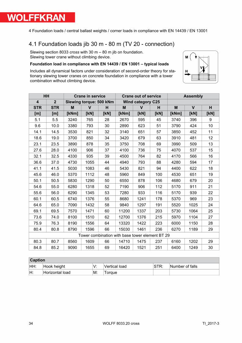
4.1 Foundation loads jib 30 m - 80 m (TV 20 - connection)Slewing section 8033 cross with 30 m – 80 m jib on foundation.Slewing tower crane without climbing device.
Foundation load in compliance with EN 14439 / EN 13001 – typical loadsIncludes all dynamical factors under consideration of second-order theory for sta-tionary slewing tower cranes on concrete foundation in compliance with a towercombination without climbing device.
H
M
V
HH Crane in service Crane out of service Assembly4 2 Slewing torque: 500 kNm Wind category C25
STR STR M V H M V H M V H[m] [m] [kNm] [kN] [kN] [kNm] [kN] [kN] [kNm] [kN] [kN]5.1 5.5 3240 765 28 2670 595 45 3740 396 99.6 10.0 3380 793 30 2890 623 51 3790 424 10
14.1 14.5 3530 821 32 3140 651 57 3850 452 1118.6 19.0 3700 850 34 3420 679 63 3910 481 1223.1 23.5 3890 878 35 3750 708 69 3990 509 1327.6 28.0 4100 906 37 4100 736 75 4070 537 1532.1 32.5 4330 935 39 4500 764 82 4170 566 1636.6 37.0 4730 1055 44 4940 793 88 4280 594 1741.1 41.5 5030 1083 46 5430 821 94 4400 622 1845.6 46.0 5370 1112 48 5960 849 100 4530 651 1950.1 50.5 5830 1290 50 6550 878 106 4680 679 2054.6 55.0 6280 1318 52 7190 906 112 5170 911 2155.6 56.0 6290 1345 53 7280 933 116 5170 939 2260.1 60.5 6740 1376 55 8680 1241 178 5370 969 2364.6 65.0 7090 1432 58 9840 1297 191 5520 1025 2469.1 69.5 7570 1471 60 11200 1337 203 5730 1064 2573.6 74.0 8100 1510 62 12700 1376 215 5970 1104 2775.9 76.3 8190 1556 64 13320 1422 223 6000 1150 2880.4 80.8 8790 1596 66 15030 1461 236 6270 1189 29
Tower combination with base tower element BT 2980.3 80.7 8560 1609 66 14710 1475 237 6160 1202 2984.8 85.2 9090 1655 69 16420 1521 251 6400 1249 30
CaptionHH: Hook height V: Vertical load STR: Number of fallsH: Horizontal load M: Torque
34
4 Foundation loads / central ballast weights / corner loads in compliance with EN 14439 / EN 13001
TI_2017-3WOLFF 8033.20 cross
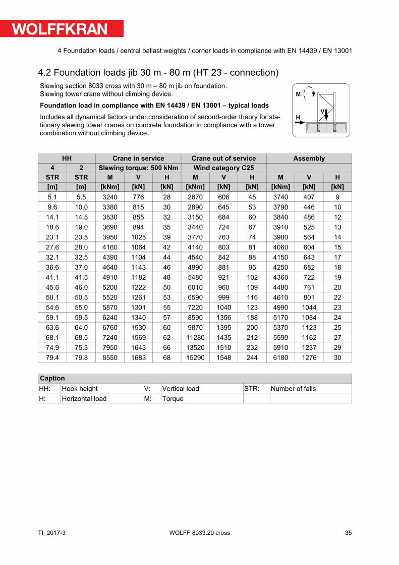
4.2 Foundation loads jib 30 m - 80 m (HT 23 - connection)Slewing section 8033 cross with 30 m – 80 m jib on foundation.Slewing tower crane without climbing device.
Foundation load in compliance with EN 14439 / EN 13001 – typical loadsIncludes all dynamical factors under consideration of second-order theory for sta-tionary slewing tower cranes on concrete foundation in compliance with a towercombination without climbing device.
H
M
V
HH Crane in service Crane out of service Assembly4 2 Slewing torque: 500 kNm Wind category C25
STR STR M V H M V H M V H[m] [m] [kNm] [kN] [kN] [kNm] [kN] [kN] [kNm] [kN] [kN]5.1 5.5 3240 776 28 2670 606 45 3740 407 99.6 10.0 3380 815 30 2890 645 53 3790 446 10
14.1 14.5 3530 855 32 3150 684 60 3840 486 1218.6 19.0 3690 894 35 3440 724 67 3910 525 1323.1 23.5 3950 1025 39 3770 763 74 3980 564 1427.6 28.0 4160 1064 42 4140 803 81 4060 604 1532.1 32.5 4390 1104 44 4540 842 88 4150 643 1736.6 37.0 4640 1143 46 4990 881 95 4250 682 1841.1 41.5 4910 1182 48 5480 921 102 4360 722 1945.6 46.0 5200 1222 50 6010 960 109 4480 761 2050.1 50.5 5520 1261 53 6590 999 116 4610 801 2254.6 55.0 5870 1301 55 7220 1040 123 4990 1044 2359.1 59.5 6240 1340 57 8590 1356 188 5170 1084 2463.6 64.0 6760 1530 60 9870 1395 200 5370 1123 2568.1 68.5 7240 1569 62 11280 1435 212 5590 1162 2774.9 75.3 7950 1643 66 13520 1510 232 5910 1237 2979.4 79.8 8550 1683 68 15290 1548 244 6180 1276 30
CaptionHH: Hook height V: Vertical load STR: Number of fallsH: Horizontal load M: Torque
35
4 Foundation loads / central ballast weights / corner loads in compliance with EN 14439 / EN 13001
TI_2017-3 WOLFF 8033.20 cross
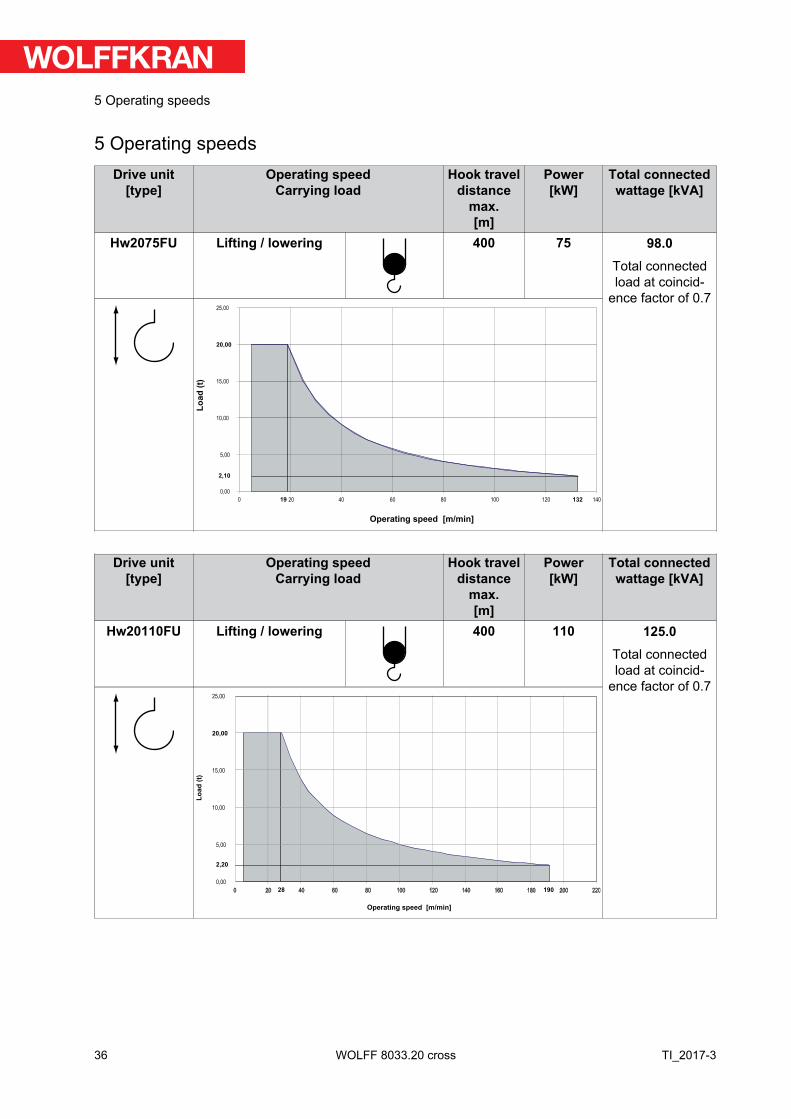
5 Operating speedsDrive unit
[type]Operating speed
Carrying loadHook travel
distancemax.[m]
Power[kW]
Total connectedwattage [kVA]
Hw2075FU Lifting / lowering 400 75 98.0Total connectedload at coincid-
ence factor of 0.7
0,00
5,00
10,00
15,00
20,00
25,00
Operating speed [m/min]
Lo
ad
(t)
19 132
2,10
0 20 40 60 80 100 120 140
Drive unit[type]
Operating speedCarrying load
Hook traveldistance
max.[m]
Power[kW]
Total connectedwattage [kVA]
Hw20110FU Lifting / lowering 400 110 125.0Total connectedload at coincid-
ence factor of 0.7
19028
2,20
0,00
5,00
10,00
15,00
20,00
25,00
0 20 40 60 80 100 120 140 160 180 200 220
Operating speed [m/min]
Lo
ad
(t)
36
5 Operating speeds
TI_2017-3WOLFF 8033.20 cross
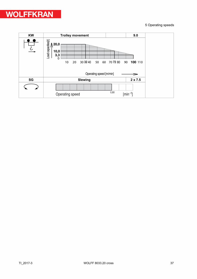
KW Trolley movement 9.0
10,0
0
10 30 40 50 60 70 80 90 100
20,0Lo
ad c
apac
ities[
t]
01102
3,3
Operating speed [m/min]
7232
SG Slewing 2 x 7.5
Operating speed [min ]-10,80
37
5 Operating speeds
TI_2017-3 WOLFF 8033.20 cross
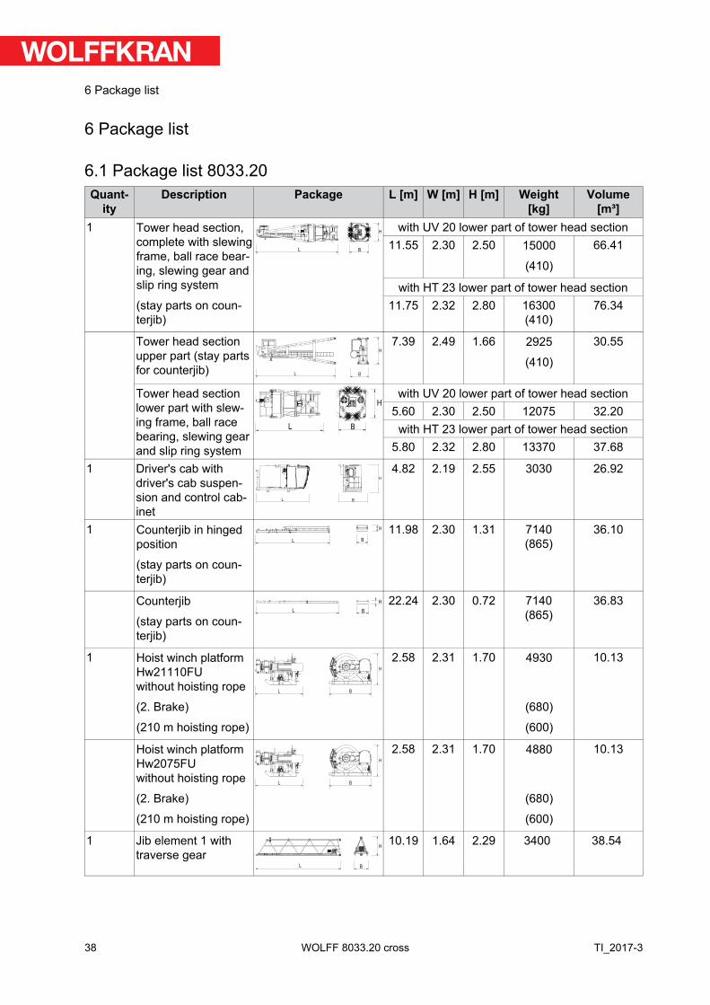
6 Package list
6.1 Package list 8033.20Quant
ityDescription Package L [m] W [m] H [m] Weight
[kg]Volume
[m³]1 Tower head section,
complete with slewingframe, ball race bear-ing, slewing gear andslip ring system
(stay parts on coun-terjib)
L B
Hwith UV 20 lower part of tower head section
11.55 2.30 2.50 15000
(410)
66.41
with HT 23 lower part of tower head section11.75 2.32 2.80 16300
(410)76.34
Tower head sectionupper part (stay partsfor counterjib) B
H
L
7.39 2.49 1.66 2925
(410)
30.55
Tower head sectionlower part with slew-ing frame, ball racebearing, slewing gearand slip ring system
L B
H
with UV 20 lower part of tower head section5.60 2.30 2.50 12075 32.20
with HT 23 lower part of tower head section5.80 2.32 2.80 13370 37.68
1 Driver's cab withdriver's cab suspen-sion and control cab-inet
L B
H
4.82 2.19 2.55 3030 26.92
1 Counterjib in hingedposition
(stay parts on coun-terjib)
L B
H 11.98 2.30 1.31 7140(865)
36.10
Counterjib
(stay parts on coun-terjib)
H
L B
22.24 2.30 0.72 7140(865)
36.83
1 Hoist winch platformHw21110FUwithout hoisting rope
(2. Brake)
(210 m hoisting rope)
L B
H
2.58 2.31 1.70 4930
(680)
(600)
10.13
Hoist winch platformHw2075FUwithout hoisting rope
(2. Brake)
(210 m hoisting rope)
L B
H
2.58 2.31 1.70 4880
(680)
(600)
10.13
1 Jib element 1 withtraverse gear
L B
H10.19 1.64 2.29 3400 38.54
38
6 Package list
TI_2017-3WOLFF 8033.20 cross
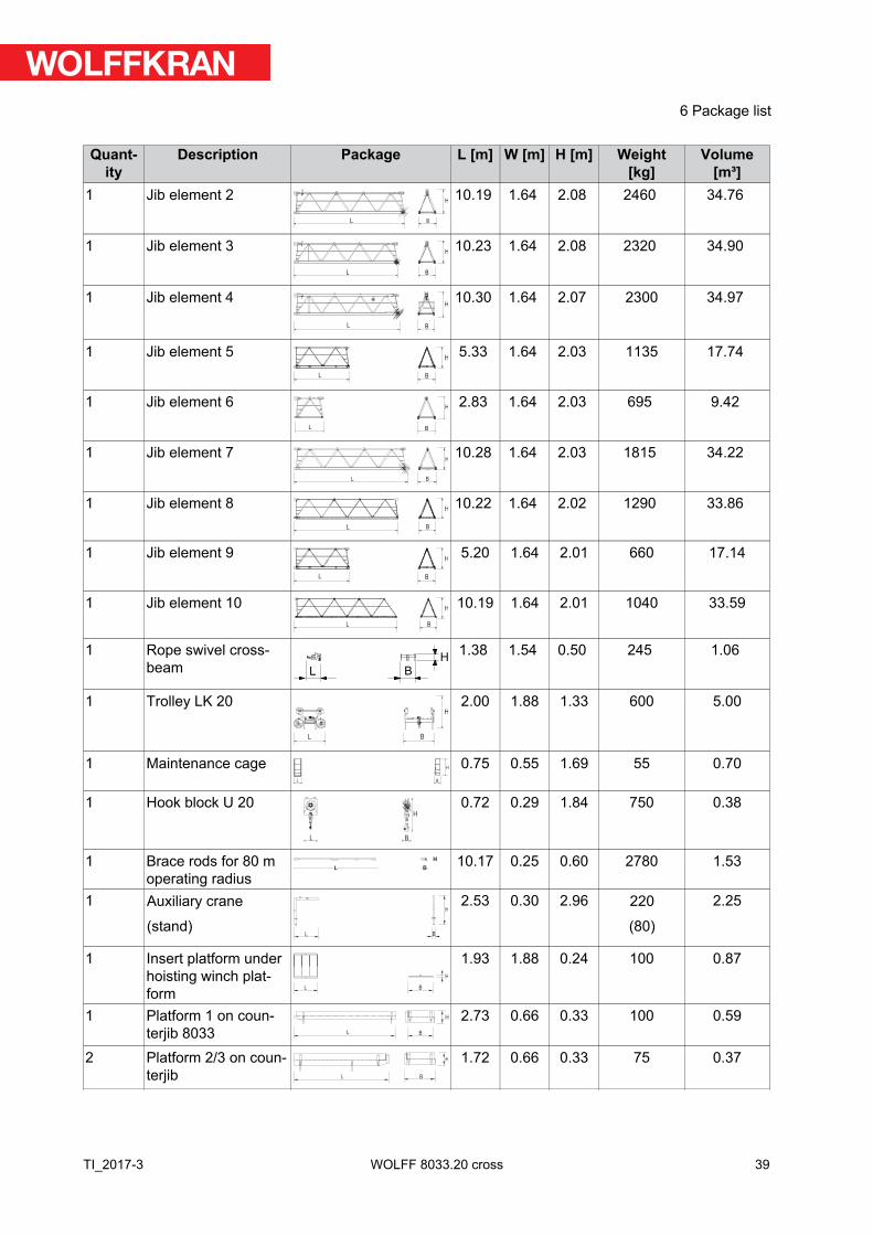
Quantity
Description Package L [m] W [m] H [m] Weight[kg]
Volume[m³]
1 Jib element 2B
H
L
10.19 1.64 2.08 2460 34.76
1 Jib element 3L
H
B
10.23 1.64 2.08 2320 34.90
1 Jib element 4
L B
H10.30 1.64 2.07 2300 34.97
1 Jib element 5H
BL
5.33 1.64 2.03 1135 17.74
1 Jib element 6B
H
L
2.83 1.64 2.03 695 9.42
1 Jib element 7L B
H10.28 1.64 2.03 1815 34.22
1 Jib element 8H
BL
10.22 1.64 2.02 1290 33.86
1 Jib element 9H
BL
5.20 1.64 2.01 660 17.14
1 Jib element 10BL
H10.19 1.64 2.01 1040 33.59
1 Rope swivel cross-beam B
H
L
1.38 1.54 0.50 245 1.06
1 Trolley LK 20
BL
H
2.00 1.88 1.33 600 5.00
1 Maintenance cageL B
H 0.75 0.55 1.69 55 0.70
1 Hook block U 20
L B
H
0.72 0.29 1.84 750 0.38
1 Brace rods for 80 moperating radius
L B
H 10.17 0.25 0.60 2780 1.53
1 Auxiliary crane
(stand)L B
H
2.53 0.30 2.96 220
(80)
2.25
1 Insert platform underhoisting winch plat-form L B
H
1.93 1.88 0.24 100 0.87
1 Platform 1 on coun-terjib 8033 L B
H 2.73 0.66 0.33 100 0.59
2 Platform 2/3 on coun-terjib L B
H 1.72 0.66 0.33 75 0.37
39
6 Package list
TI_2017-3 WOLFF 8033.20 cross
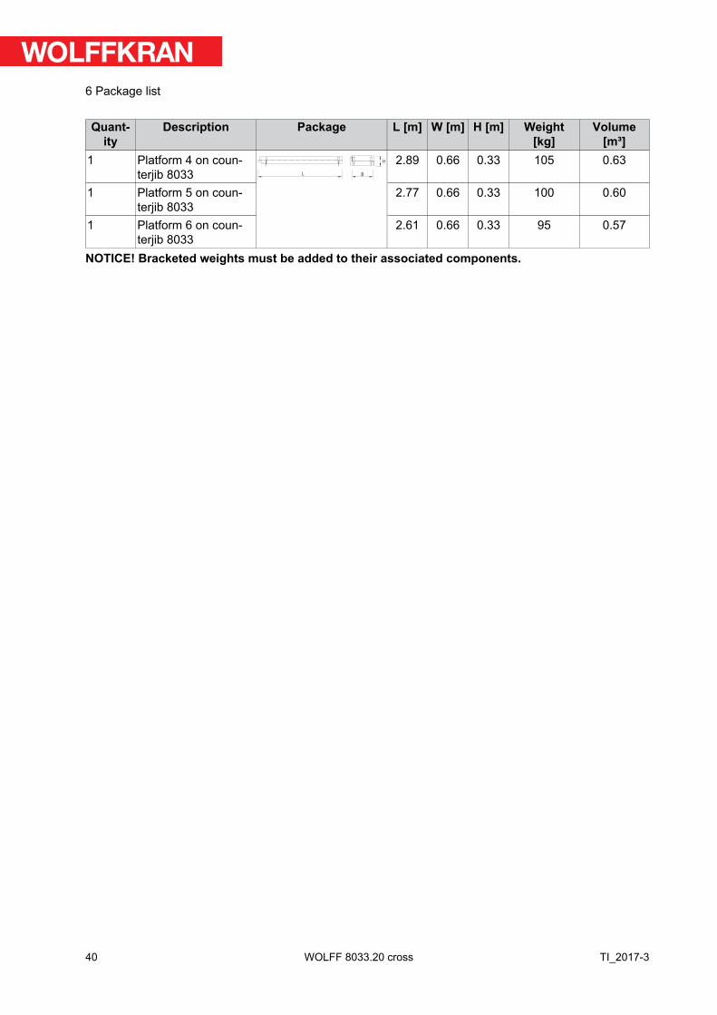
Quantity
Description Package L [m] W [m] H [m] Weight[kg]
Volume[m³]
1 Platform 4 on coun-terjib 8033 L B
H 2.89 0.66 0.33 105 0.63
1 Platform 5 on coun-terjib 8033
2.77 0.66 0.33 100 0.60
1 Platform 6 on coun-terjib 8033
2.61 0.66 0.33 95 0.57
NOTICE! Bracketed weights must be added to their associated components.
40
6 Package list
TI_2017-3WOLFF 8033.20 cross

7 Assembly weights
7.1 Counterweight blocks
!NOTICE
The described diagrams of the concrete counterweights and central ballastblocks only show sketches. Have them issue the reinforcement charts byexperts.
41
7 Assembly weights
TI_2017-3 WOLFF 8033.20 cross
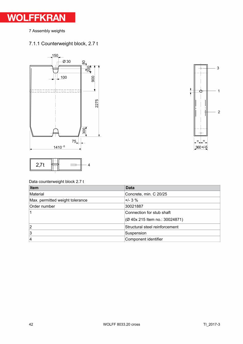
7.1.1 Counterweight block, 2.7 t
2,7t
20
0
22
75
75
3601410
Ø 30
150
90
0
80
30
0
= =
100
+/-5
1
2
4
3
-5
Data counterweight block 2.7 tItem DataMaterial Concrete, min. C 20/25Max. permitted weight tolerance +/- 3 %Order number 300218871 Connection for stub shaft
(Ø 40x 215 Item no.: 30024871)
2 Structural steel reinforcement3 Suspension4 Component identifier
42
7 Assembly weights
TI_2017-3WOLFF 8033.20 cross
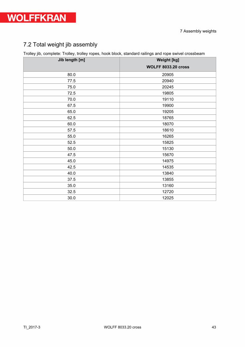
7.2 Total weight jib assemblyTrolley jib, complete: Trolley, trolley ropes, hook block, standard railings and rope swivel crossbeam
Jib length [m] Weight [kg]WOLFF 8033.20 cross
80.0 2090577.5 2094075.0 2024572.5 1980570.0 1911067.5 1990065.0 1920562.5 1876560.0 1807057.5 1861055.0 1626552.5 1582550.0 1513047.5 1567045.0 1497542.5 1453540.0 1384037.5 1385535.0 1316032.5 1272030.0 12025
43
7 Assembly weights
TI_2017-3 WOLFF 8033.20 cross
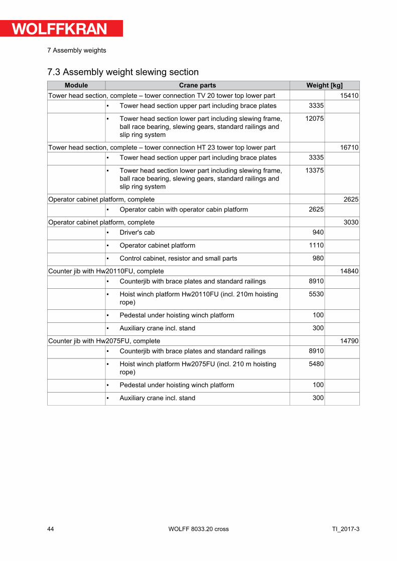
7.3 Assembly weight slewing sectionModule Crane parts Weight [kg]
Tower head section, complete – tower connection TV 20 tower top lower part 15410▪ Tower head section upper part including brace plates 3335
▪ Tower head section lower part including slewing frame,ball race bearing, slewing gears, standard railings andslip ring system
12075
Tower head section, complete – tower connection HT 23 tower top lower part 16710▪ Tower head section upper part including brace plates 3335
▪ Tower head section lower part including slewing frame,ball race bearing, slewing gears, standard railings andslip ring system
13375
Operator cabinet platform, complete 2625▪ Operator cabin with operator cabin platform 2625
Operator cabinet platform, complete 3030▪ Driver's cab 940
▪ Operator cabinet platform 1110
▪ Control cabinet, resistor and small parts 980
Counter jib with Hw20110FU, complete 14840▪ Counterjib with brace plates and standard railings 8910
▪ Hoist winch platform Hw20110FU (incl. 210m hoistingrope)
5530
▪ Pedestal under hoisting winch platform 100
▪ Auxiliary crane incl. stand 300
Counter jib with Hw2075FU, complete 14790▪ Counterjib with brace plates and standard railings 8910
▪ Hoist winch platform Hw2075FU (incl. 210 m hoistingrope)
5480
▪ Pedestal under hoisting winch platform 100
▪ Auxiliary crane incl. stand 300
44
7 Assembly weights
TI_2017-3WOLFF 8033.20 cross
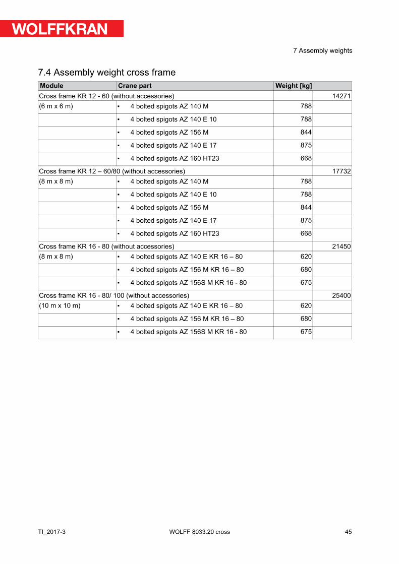
7.4 Assembly weight cross frameModule Crane part Weight [kg]Cross frame KR 12 - 60 (without accessories) 14271(6 m x 6 m) ▪ 4 bolted spigots AZ 140 M 788
▪ 4 bolted spigots AZ 140 E 10 788
▪ 4 bolted spigots AZ 156 M 844
▪ 4 bolted spigots AZ 140 E 17 875
▪ 4 bolted spigots AZ 160 HT23 668
Cross frame KR 12 – 60/80 (without accessories) 17732(8 m x 8 m) ▪ 4 bolted spigots AZ 140 M 788
▪ 4 bolted spigots AZ 140 E 10 788
▪ 4 bolted spigots AZ 156 M 844
▪ 4 bolted spigots AZ 140 E 17 875
▪ 4 bolted spigots AZ 160 HT23 668
Cross frame KR 16 - 80 (without accessories) 21450(8 m x 8 m) ▪ 4 bolted spigots AZ 140 E KR 16 – 80 620
▪ 4 bolted spigots AZ 156 M KR 16 – 80 680
▪ 4 bolted spigots AZ 156S M KR 16 - 80 675
Cross frame KR 16 - 80/ 100 (without accessories) 25400(10 m x 10 m) ▪ 4 bolted spigots AZ 140 E KR 16 – 80 620
▪ 4 bolted spigots AZ 156 M KR 16 – 80 680
▪ 4 bolted spigots AZ 156S M KR 16 - 80 675
45
7 Assembly weights
TI_2017-3 WOLFF 8033.20 cross

7.5 Assembly weights traveling cross frameModule Crane part Weight [kg]Traveling cross frame KRF4 12-60/80 complete 32300(8.0 m x 8.0 m) ▪ Cross frame 14170
▪ Backing braces 2875
▪ Drive gear corners 4560
▪ Subframe 9380
▪ Platforms and ladders 255
▪ Control cabinet 130
▪ small items 930
▪ Set of bolted spigots AZR 140 M KR 12-60/80 790
▪ Set of bolted spigots AZ 120 E 15,5 KR 12-60/80 730
▪ Set of bolted spigots AZ 140 E 15,5 KR 12-60/80 875
▪ Set of bolted spigots AZR 160 M KR 12-60/80 905
▪ Set of bolted spigots AZ 140 E 10 KR 12-60/80 790
▪ Set of bolted spigots AZR 156 M KR 12-60/80 845
Traveling cross frame KRF6 12-60/80 complete 41200(8.0 m x 8.0 m) ▪ Cross frame 14170
▪ Backing braces 2875
▪ Drive gear corners 4560
▪ Subframe 18270
▪ Platforms and ladders 255
▪ Control cabinet 130
▪ small items 940
▪ Set of bolted spigots AZR 140 M KR 12-60/80 790
▪ Set of bolted spigots AZ 120 E 15,5 KR 12-60/80 730
▪ Set of bolted spigots AZ 140 E 15,5 KR 12-60/80 875
▪ Set of bolted spigots AZR 160 M KR 12-60/80 905
▪ Set of bolted spigots AZ 140 E 10 KR 12-60/80 790
▪ Set of bolted spigots AZR 156 M KR 12-60/80 845
46
7 Assembly weights
TI_2017-3WOLFF 8033.20 cross
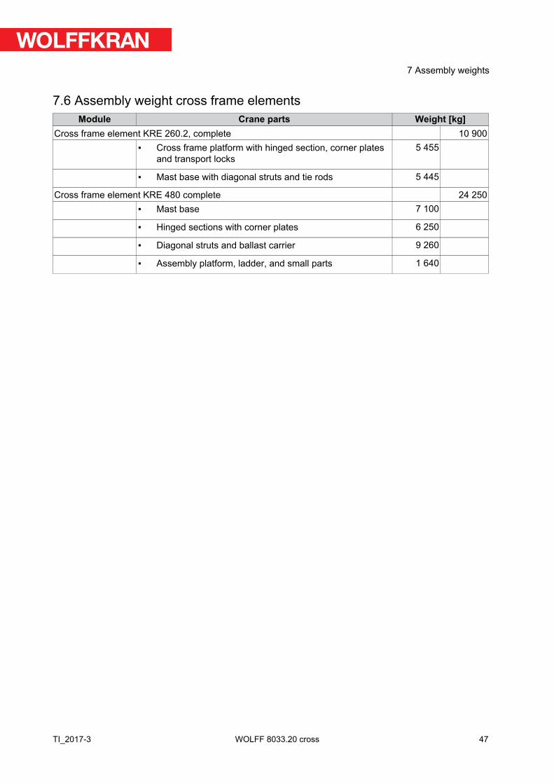
7.6 Assembly weight cross frame elementsModule Crane parts Weight [kg]
Cross frame element KRE 260.2, complete 10 900▪ Cross frame platform with hinged section, corner plates
and transport locks5 455
▪ Mast base with diagonal struts and tie rods 5 445
Cross frame element KRE 480 complete 24 250▪ Mast base 7 100
▪ Hinged sections with corner plates 6 250
▪ Diagonal struts and ballast carrier 9 260
▪ Assembly platform, ladder, and small parts 1 640
47
7 Assembly weights
TI_2017-3 WOLFF 8033.20 cross
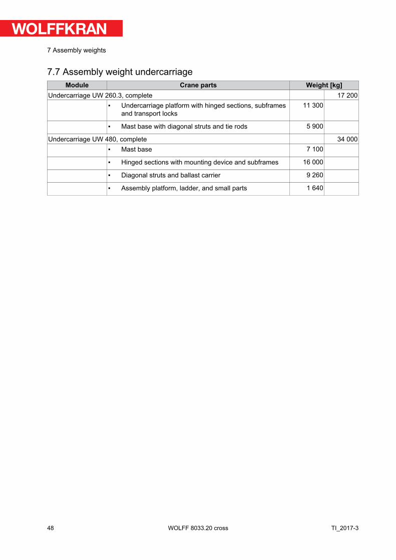
7.7 Assembly weight undercarriageModule Crane parts Weight [kg]
Undercarriage UW 260.3, complete 17 200▪ Undercarriage platform with hinged sections, subframes
and transport locks11 300
▪ Mast base with diagonal struts and tie rods 5 900
Undercarriage UW 480, complete 34 000▪ Mast base 7 100
▪ Hinged sections with mounting device and subframes 16 000
▪ Diagonal struts and ballast carrier 9 260
▪ Assembly platform, ladder, and small parts 1 640
48
7 Assembly weights
TI_2017-3WOLFF 8033.20 cross
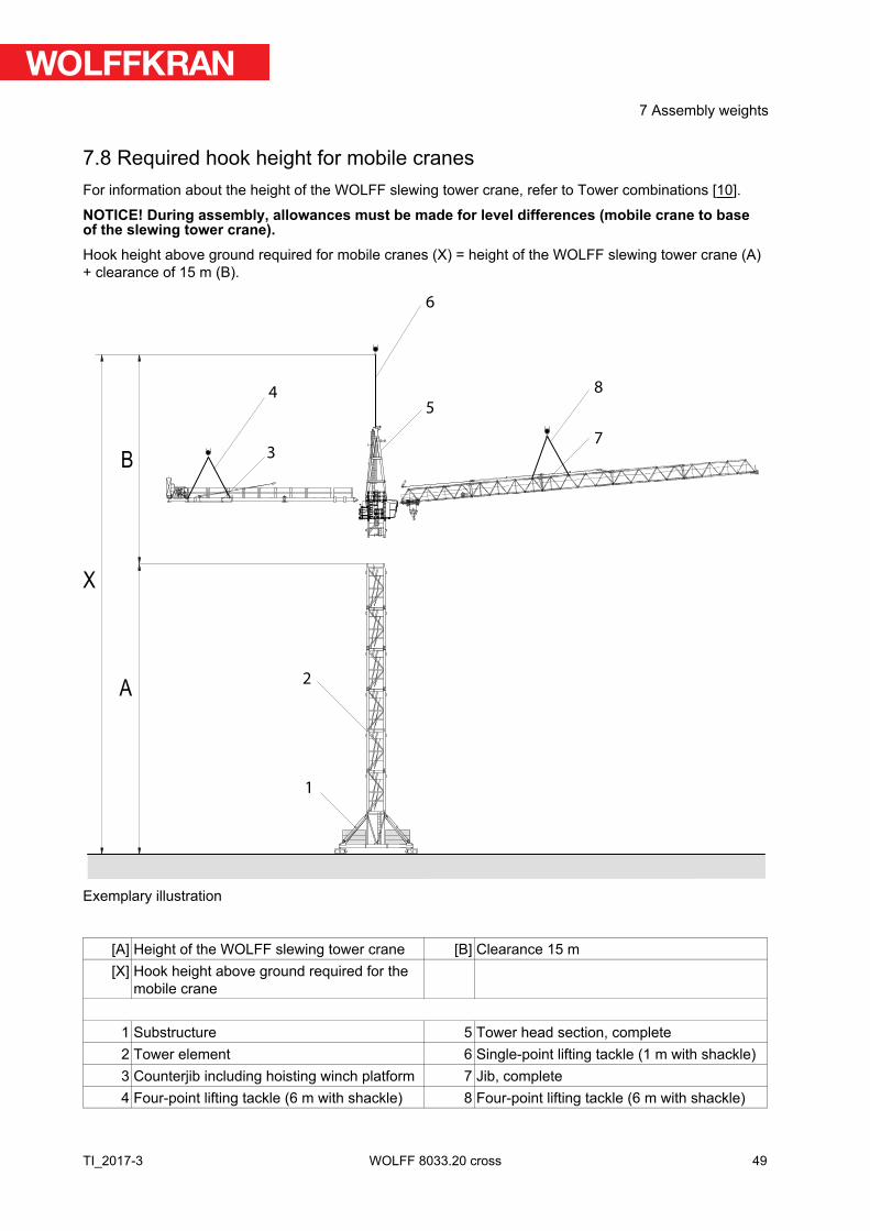
7.8 Required hook height for mobile cranesFor information about the height of the WOLFF slewing tower crane, refer to Tower combinations [10].
NOTICE! During assembly, allowances must be made for level differences (mobile crane to baseof the slewing tower crane). Hook height above ground required for mobile cranes (X) = height of the WOLFF slewing tower crane (A)+ clearance of 15 m (B).
X
B
A
3
4
6
5
8
7
1
2
Exemplary illustration
[A] Height of the WOLFF slewing tower crane [B] Clearance 15 m[X] Hook height above ground required for the
mobile crane
1 Substructure 5 Tower head section, complete2 Tower element 6 Single-point lifting tackle (1 m with shackle) 3 Counterjib including hoisting winch platform 7 Jib, complete4 Four-point lifting tackle (6 m with shackle) 8 Four-point lifting tackle (6 m with shackle)
49
7 Assembly weights
TI_2017-3 WOLFF 8033.20 cross
(see also):▪ Tower combinations [10]
50
7 Assembly weights
TI_2017-3WOLFF 8033.20 cross
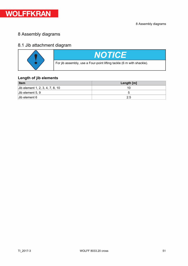
8 Assembly diagrams
8.1 Jib attachment diagram
!NOTICE
For jib assembly, use a Four-point lifting tackle (6 m with shackle).
Length of jib elementsItem Length [m]Jib element 1, 2, 3, 4, 7, 8, 10 10Jib element 5, 9 5Jib element 6 2.5
51
8 Assembly diagrams
TI_2017-3 WOLFF 8033.20 cross
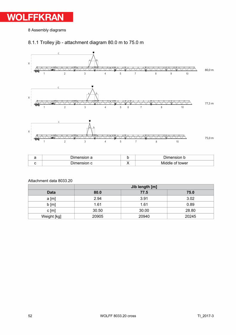
8.1.1 Trolley jib - attachment diagram 80.0 m to 75.0 m
a b
a b
80,0 m
77,5 m
75,0 m
a b
C
C
C
X
X
X
1 2 3 4 5 7 8 9 10
1 2 3 4 5 6 7 8 10
1 2 3 4 5 7 8 10
a Dimension a b Dimension bc Dimension c X Middle of tower
Attachment data 8033.20Jib length [m]
Data 80.0 77.5 75.0a [m] 2.94 3.91 3.02b [m] 1.61 1.61 0.89c [m] 30.50 30.00 28.80
Weight [kg] 20905 20940 20245
52
8 Assembly diagrams
TI_2017-3WOLFF 8033.20 cross
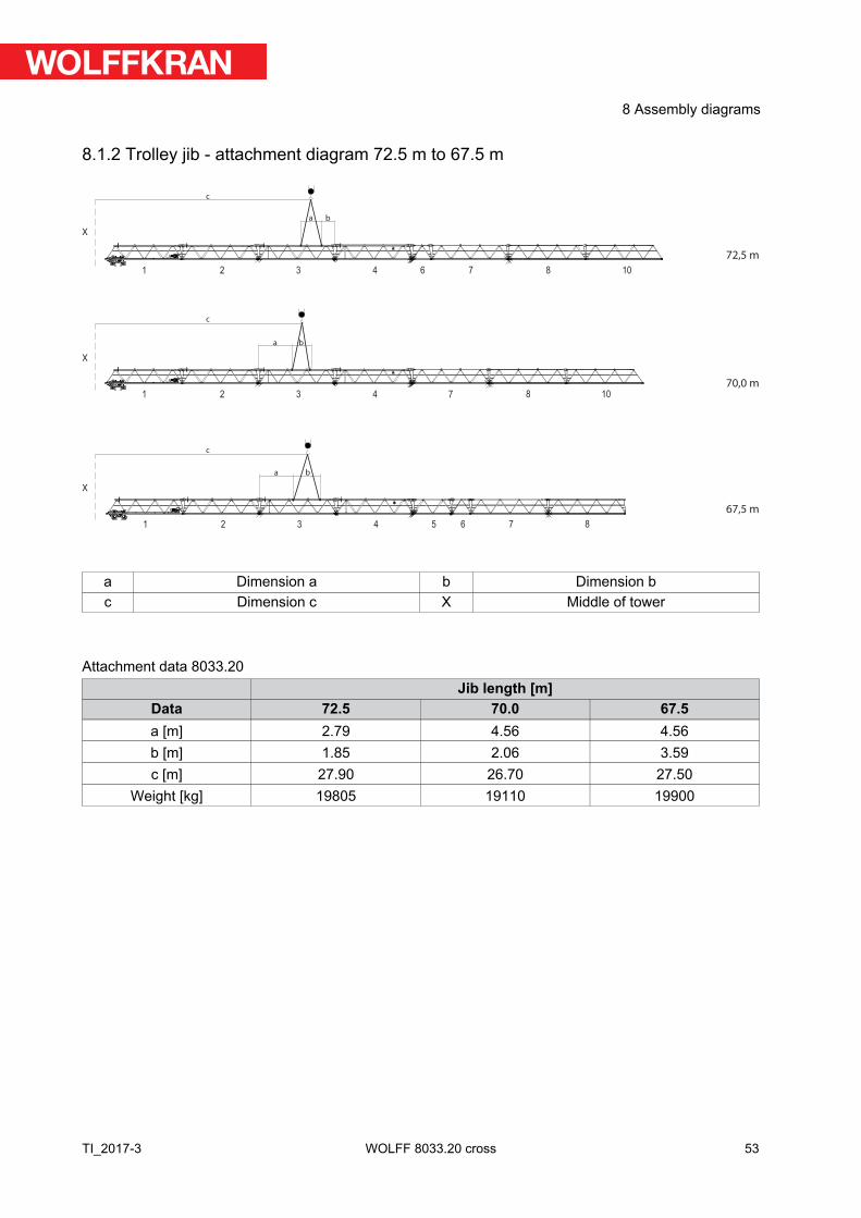
8.1.2 Trolley jib - attachment diagram 72.5 m to 67.5 m
a b
a b
a b
c
c
c
72,5 m
70,0 m
67,5 m
X
X
X
1 2 3 4 6 7 8 10
1 2 3 4 7 8 10
1 2 3 4 5 6 7 8
a Dimension a b Dimension bc Dimension c X Middle of tower
Attachment data 8033.20Jib length [m]
Data 72.5 70.0 67.5a [m] 2.79 4.56 4.56b [m] 1.85 2.06 3.59c [m] 27.90 26.70 27.50
Weight [kg] 19805 19110 19900
53
8 Assembly diagrams
TI_2017-3 WOLFF 8033.20 cross

8.1.3 Trolley jib - attachment diagram 65.0 m to 60.0 m
a b
a b
a b
60,0 m
62,5 m
65,0 m
c
c
c
X
X
X
1 2 3 4 5 7 8
1 2 3 4 6 7 8
1 2 3 4 7 8
a Dimension a b Dimension bc Dimension c X Middle of tower
Attachment data 8033.20Jib length [m]
Data 65.0 62.5 60.0a [m] 2.86 2.06 1.09b [m] 4.49 4.56 4.56c [m] 26.30 25.50 24.50
Weight [kg] 19205 18765 18070
54
8 Assembly diagrams
TI_2017-3WOLFF 8033.20 cross
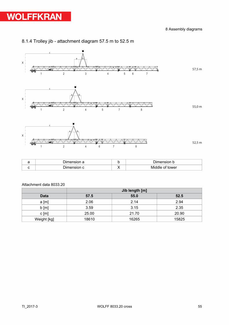
8.1.4 Trolley jib - attachment diagram 57.5 m to 52.5 m
a b
a b
a b
c
c
c
57,5 m
55,0 m
52,5 m
X
X
X
1 2 3 4 5 6 7
1 2 4 5 7 8
1 2 4 6 7 8
a Dimension a b Dimension bc Dimension c X Middle of tower
Attachment data 8033.20Jib length [m]
Data 57.5 55.0 52.5a [m] 2.06 2.14 2.94b [m] 3.59 3.15 2.35c [m] 25.00 21.70 20.90
Weight [kg] 18610 16265 15825
55
8 Assembly diagrams
TI_2017-3 WOLFF 8033.20 cross
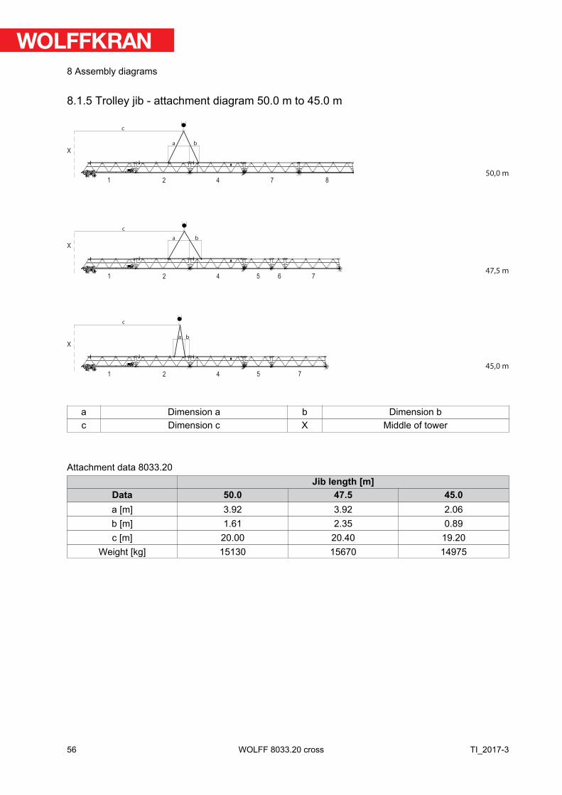
8.1.5 Trolley jib - attachment diagram 50.0 m to 45.0 m
a b
a b
50,0 m
47,5 m
45,0 m
a b
c
c
c
X
X
X
1 2 4 7 8
1 2 4 5 6 7
1 2 4 5 7
a Dimension a b Dimension bc Dimension c X Middle of tower
Attachment data 8033.20Jib length [m]
Data 50.0 47.5 45.0a [m] 3.92 3.92 2.06b [m] 1.61 2.35 0.89c [m] 20.00 20.40 19.20
Weight [kg] 15130 15670 14975
56
8 Assembly diagrams
TI_2017-3WOLFF 8033.20 cross
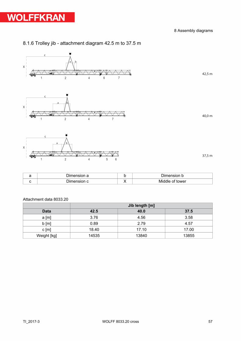
8.1.6 Trolley jib - attachment diagram 42.5 m to 37.5 m
a b
a b
a b
42,5 m
40,0 m
37,5 m
c
c
c
X
X
X
1 2 4 6 7
1 2 4 7
1 2 4 5 6
a Dimension a b Dimension bc Dimension c X Middle of tower
Attachment data 8033.20Jib length [m]
Data 42.5 40.0 37.5a [m] 3.76 4.56 3.58b [m] 0.89 2.79 4.57c [m] 18.40 17.10 17.00
Weight [kg] 14535 13840 13855
57
8 Assembly diagrams
TI_2017-3 WOLFF 8033.20 cross
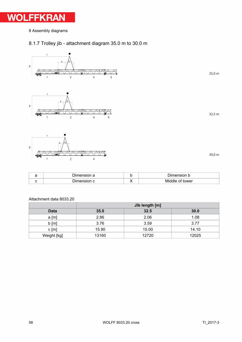
8.1.7 Trolley jib - attachment diagram 35.0 m to 30.0 m
a b
a b
a b
35,0 m
32,5 m
30,0 m
c
c
c
X
X
X
1 2 4 5
1 2 4 6
1 2 4
a Dimension a b Dimension bc Dimension c X Middle of tower
Attachment data 8033.20Jib length [m]
Data 35.0 32.5 30.0a [m] 2.86 2.06 1.08b [m] 3.76 3.59 3.77c [m] 15.90 15.00 14.10
Weight [kg] 13160 12720 12025
58
8 Assembly diagrams
TI_2017-3WOLFF 8033.20 cross
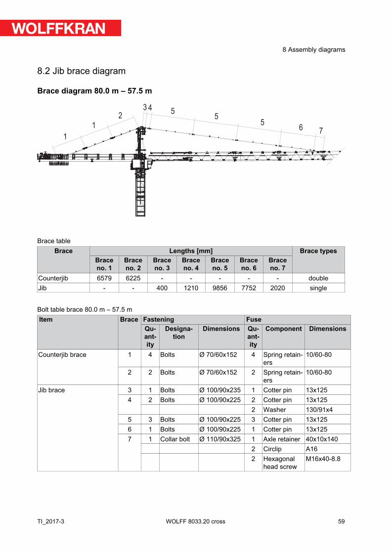
8.2 Jib brace diagram
Brace diagram 80.0 m – 57.5 m
1
1
2
43
55
67
5
Brace tableBrace Lengths [mm] Brace types
Braceno. 1
Braceno. 2
Braceno. 3
Braceno. 4
Braceno. 5
Braceno. 6
Braceno. 7
Counterjib 6579 6225 - - - - - doubleJib - - 400 1210 9856 7752 2020 single
Bolt table brace 80.0 m – 57.5 mItem Brace Fastening Fuse
Quantity
Designation
Dimensions Quantity
Component Dimensions
Counterjib brace 1 4 Bolts Ø 70/60x152 4 Spring retain-ers
10/60-80
2 2 Bolts Ø 70/60x152 2 Spring retain-ers
10/60-80
Jib brace 3 1 Bolts Ø 100/90x235 1 Cotter pin 13x1254 2 Bolts Ø 100/90x225 2 Cotter pin 13x125
2 Washer 130/91x45 3 Bolts Ø 100/90x225 3 Cotter pin 13x1256 1 Bolts Ø 100/90x225 1 Cotter pin 13x1257 1 Collar bolt Ø 110/90x325 1 Axle retainer 40x10x140
2 Circlip A162 Hexagonal
head screwM16x40-8.8
59
8 Assembly diagrams
TI_2017-3 WOLFF 8033.20 cross
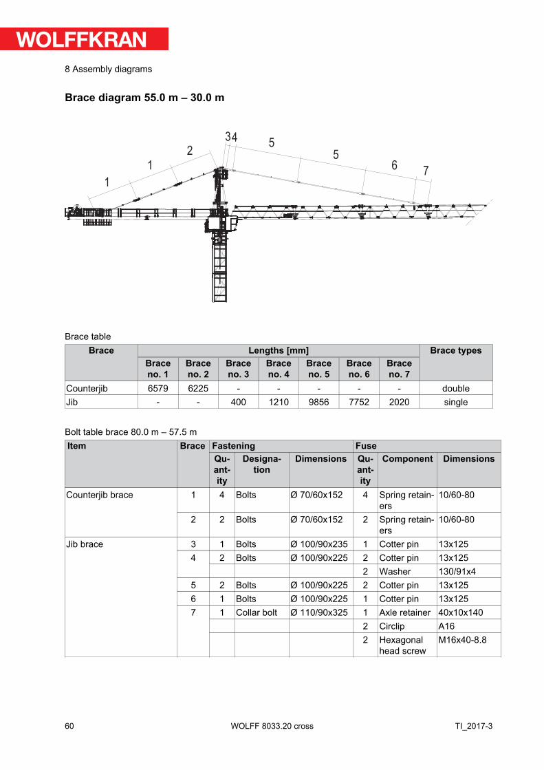
Brace diagram 55.0 m – 30.0 m
1
1
2
435
56
7
Brace tableBrace Lengths [mm] Brace types
Braceno. 1
Braceno. 2
Braceno. 3
Braceno. 4
Braceno. 5
Braceno. 6
Braceno. 7
Counterjib 6579 6225 - - - - - doubleJib - - 400 1210 9856 7752 2020 single
Bolt table brace 80.0 m – 57.5 mItem Brace Fastening Fuse
Quantity
Designation
Dimensions Quantity
Component Dimensions
Counterjib brace 1 4 Bolts Ø 70/60x152 4 Spring retain-ers
10/60-80
2 2 Bolts Ø 70/60x152 2 Spring retain-ers
10/60-80
Jib brace 3 1 Bolts Ø 100/90x235 1 Cotter pin 13x1254 2 Bolts Ø 100/90x225 2 Cotter pin 13x125
2 Washer 130/91x45 2 Bolts Ø 100/90x225 2 Cotter pin 13x1256 1 Bolts Ø 100/90x225 1 Cotter pin 13x1257 1 Collar bolt Ø 110/90x325 1 Axle retainer 40x10x140
2 Circlip A162 Hexagonal
head screwM16x40-8.8
60
8 Assembly diagrams
TI_2017-3WOLFF 8033.20 cross
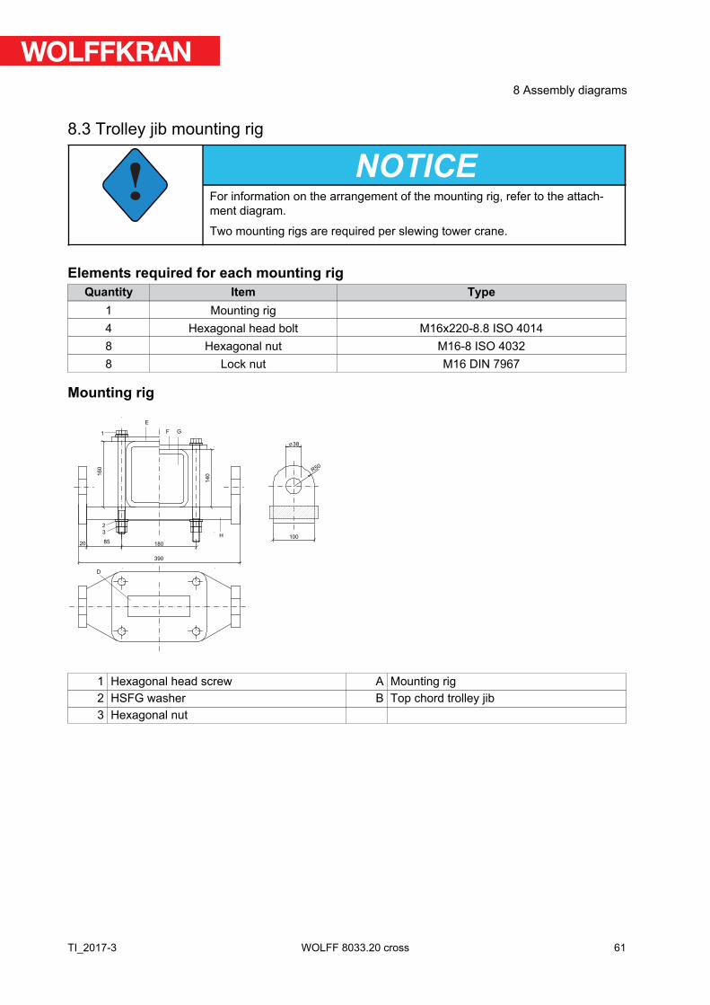
8.3 Trolley jib mounting rig
!NOTICE
For information on the arrangement of the mounting rig, refer to the attach-ment diagram.
Two mounting rigs are required per slewing tower crane.
Elements required for each mounting rigQuantity Item Type
1 Mounting rig4 Hexagonal head bolt M16x220-8.8 ISO 40148 Hexagonal nut M16-8 ISO 40328 Lock nut M16 DIN 7967
Mounting rig
100
38
R50
1
2
3
390
20 85180
140160
D
E
F
H
G
1 Hexagonal head screw A Mounting rig2 HSFG washer B Top chord trolley jib3 Hexagonal nut
61
8 Assembly diagrams
TI_2017-3 WOLFF 8033.20 cross
8.4 Arrangement of standard railings
8.4.1 Standard railings (NG) and accessories
Quantity
Standard railings (NG) / accessories Article no.
10 Standard railing NG 2500 3001879812 Standard railing NG 2000 300187973 Standard railing NG 1500 300187962 Standard railing NG 1000 300187952 Standard railing NG 750 3001879411 Standard railings NG 500 300187934 Standard posts Ø 42.4 mm x 1090 mm 300001671 RS (hoop guard) 300442441 Support block 645 mm (AB 1) 300506951 Support block 1140 mm (AB 2) 30050697
62
8 Assembly diagrams
TI_2017-3WOLFF 8033.20 cross
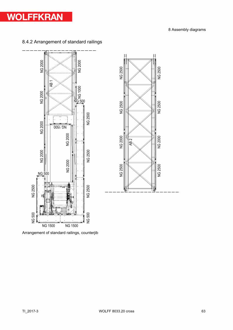
8.4.2 Arrangement of standard railings
NG
50
0
NG 1500 NG 1500
NG
50
0
NG
25
00
NG 500
AB
1
NG
20
00
NG
20
00
NG
20
00
NG
20
00
NG
20
00
NG 1500
NG
20
00
NG
25
00
NG
25
00
NG
25
00
NG 500
NG
10
00
NG
20
00
NG
25
00
NG
25
00
NG
20
00
NG
20
00
NG
25
00
NG
25
00
NG
25
00
NG
25
00
AB
2
Arrangement of standard railings, counterjib
63
8 Assembly diagrams
TI_2017-3 WOLFF 8033.20 cross
NG 750
NG 500
NG
50
0
NG 500
NG
10
00
RSNP
F
NPF
NG 500
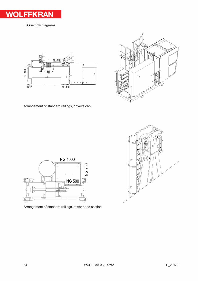
Arrangement of standard railings, driver's cab
NG 1000
NG
75
0
NG 500
Arrangement of standard railings, tower head section
64
8 Assembly diagrams
TI_2017-3WOLFF 8033.20 cross
NG 2000
2 x NPF
NG
50
0
NG
500
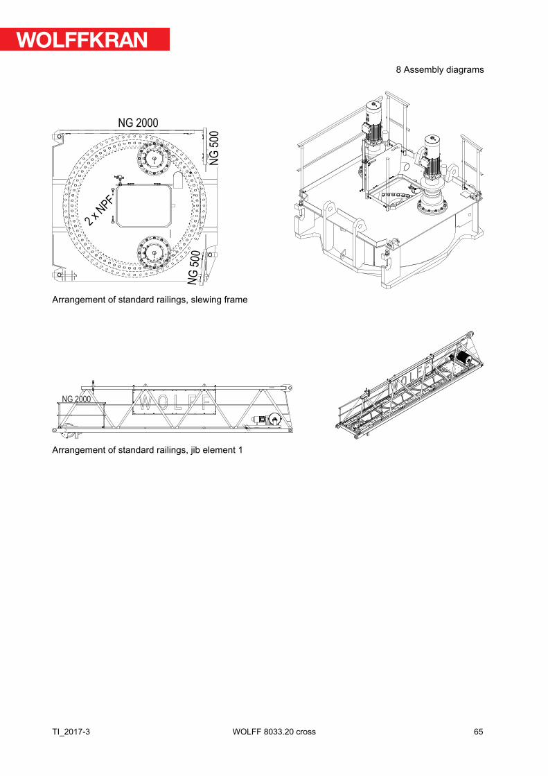
Arrangement of standard railings, slewing frame
NG 2000
Arrangement of standard railings, jib element 1
65
8 Assembly diagrams
TI_2017-3 WOLFF 8033.20 cross
9 Suitable climbing devices
This section contains information on
▪ Outer climbing devices (KWH)▪ Inner climbing devices (KSH)
!NOTICE
Details on the climbing device
Always refer to the details in the documentation of the climbing device.
!NOTICE
The operating radius specified is measured from the tower center and is to beconsidered a reference value. Exact balancing can be achieved by changingthe operating radius with the tower elements or loads specified in the table.
!NOTICE
Details for climbing balancing
The climbing balancing details apply to the snatch block in maximum hookposition.
!NOTICE
If feasible, preferably operate your climbing device without balancing weight.
66
9 Suitable climbing devices
TI_2017-3WOLFF 8033.20 cross
9.1 Outer climbing devices
DANGERClimbing device attached to the lower part of the tower head section lowerpart.
Increased wind surface. The slewing tower crane may overturn.
► Dismantle the climbing device after the climbing procedure is finished orlower the climbing device down on the ground or lower the climbingdevice down to the uppermost tower brace.
!NOTICE
Tower element on the transfer carriage
The data on climbing balance was specified under the assumption that atower element is on the transfer carriage.
67
9 Suitable climbing devices
TI_2017-3 WOLFF 8033.20 cross
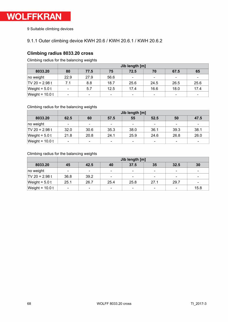
9.1.1 Outer climbing device KWH 20.6 / KWH 20.6.1 / KWH 20.6.2
Climbing radius 8033.20 crossClimbing radius for the balancing weights
Jib length [m]8033.20 80 77.5 75 72.5 70 67.5 65
no weight 22.9 27.9 56.6 - - - -TV 20 = 2.98 t 7.1 8.8 18.7 25.6 24.5 26.5 25.6Weight = 5.0 t - 5.7 12.5 17.4 16.6 18.0 17.4Weight = 10.0 t - - - - - - -
Climbing radius for the balancing weightsJib length [m]
8033.20 62.5 60 57.5 55 52.5 50 47.5no weight - - - - - - -TV 20 = 2.98 t 32.0 30.6 35.3 38.0 36.1 39.3 38.1Weight = 5.0 t 21.8 20.8 24.1 25.9 24.6 26.8 26.0Weight = 10.0 t - - - - - - -
Climbing radius for the balancing weightsJib length [m]
8033.20 45 42.5 40 37.5 35 32.5 30no weight - - - - - - -TV 20 = 2.98 t 36.8 39.2 - - - - -Weight = 5.0 t 25.1 26.7 25.4 25.8 27.1 29.7 -Weight = 10.0 t - - - - - - 15.8
68
9 Suitable climbing devices
TI_2017-3WOLFF 8033.20 cross
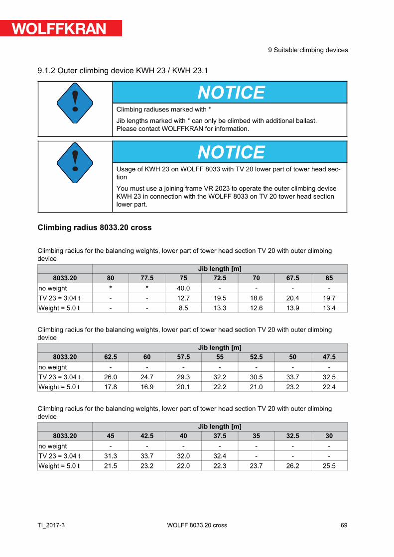
9.1.2 Outer climbing device KWH 23 / KWH 23.1
!NOTICE
Climbing radiuses marked with *
Jib lengths marked with * can only be climbed with additional ballast.Please contact WOLFFKRAN for information.
!NOTICE
Usage of KWH 23 on WOLFF 8033 with TV 20 lower part of tower head sec-tion
You must use a joining frame VR 2023 to operate the outer climbing deviceKWH 23 in connection with the WOLFF 8033 on TV 20 tower head sectionlower part.
Climbing radius 8033.20 cross
Climbing radius for the balancing weights, lower part of tower head section TV 20 with outer climbingdevice
Jib length [m]8033.20 80 77.5 75 72.5 70 67.5 65
no weight * * 40.0 - - - -TV 23 = 3.04 t - - 12.7 19.5 18.6 20.4 19.7Weight = 5.0 t - - 8.5 13.3 12.6 13.9 13.4
Climbing radius for the balancing weights, lower part of tower head section TV 20 with outer climbingdevice
Jib length [m]8033.20 62.5 60 57.5 55 52.5 50 47.5
no weight - - - - - - -TV 23 = 3.04 t 26.0 24.7 29.3 32.2 30.5 33.7 32.5Weight = 5.0 t 17.8 16.9 20.1 22.2 21.0 23.2 22.4
Climbing radius for the balancing weights, lower part of tower head section TV 20 with outer climbingdevice
Jib length [m]8033.20 45 42.5 40 37.5 35 32.5 30
no weight - - - - - - -TV 23 = 3.04 t 31.3 33.7 32.0 32.4 - - -Weight = 5.0 t 21.5 23.2 22.0 22.3 23.7 26.2 25.5
69
9 Suitable climbing devices
TI_2017-3 WOLFF 8033.20 cross
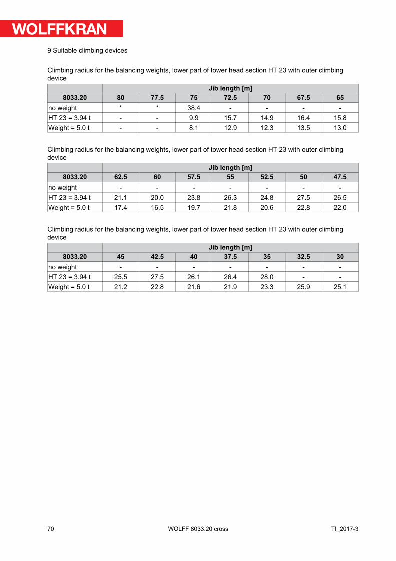
Climbing radius for the balancing weights, lower part of tower head section HT 23 with outer climbingdevice
Jib length [m]8033.20 80 77.5 75 72.5 70 67.5 65
no weight * * 38.4 - - - -HT 23 = 3.94 t - - 9.9 15.7 14.9 16.4 15.8Weight = 5.0 t - - 8.1 12.9 12.3 13.5 13.0
Climbing radius for the balancing weights, lower part of tower head section HT 23 with outer climbingdevice
Jib length [m]8033.20 62.5 60 57.5 55 52.5 50 47.5
no weight - - - - - - -HT 23 = 3.94 t 21.1 20.0 23.8 26.3 24.8 27.5 26.5Weight = 5.0 t 17.4 16.5 19.7 21.8 20.6 22.8 22.0
Climbing radius for the balancing weights, lower part of tower head section HT 23 with outer climbingdevice
Jib length [m]8033.20 45 42.5 40 37.5 35 32.5 30
no weight - - - - - - -HT 23 = 3.94 t 25.5 27.5 26.1 26.4 28.0 - -Weight = 5.0 t 21.2 22.8 21.6 21.9 23.3 25.9 25.1
70
9 Suitable climbing devices
TI_2017-3WOLFF 8033.20 cross
9.2 Inner climbing devices
!NOTICE
The data required and the instructions for tower assemblies with inner climb-ing device is available in the separate description of the inner climbing device.
DANGER! Observe the special tower combination for the inner climbing device.
!NOTICE
Clamping forces for the inner climbing device (KSH) are specified based on abuilding height of < 250m and wind category C 25.
71
9 Suitable climbing devices
TI_2017-3 WOLFF 8033.20 cross

9.2.1 Inner climbing device KSH 20 SH
Tower combinations for slewing tower cranes with inner climbing device.Item
1 TV 20.4 TV 20.4 TV 20.4 TV 20.42 TV 20.4 TV 20.4 TV 20.4 TV 20.43 TV 20.4 TV 20.4 TV 20.4 TV 20.44 TV 20.4 TV 20.4 TV 20.4 TV 20.45 TV 20.4 TV 20.4 TV 20.4 TV 20.46 TV 20.4 TV 20.4 TV 20.4 TV 20.47 TV 20.4 TV 20.4 TV 20.48 TV 20.4 TV 20.49 TV 20.4
inner climbing device KSH 20 SH KSH 20 SH KSH 20 SH KSH 20 SHFoundation FUA TYPE FS-156 / FUA 156S FUA TYPE FS-156 / FUA 156S FUA TYPE FS-156 / FUA 156S FUA TYPE FS-156 / FUA 156S
Tower height [m] 55.5 51.0 46.5 42.0Hook height
(2 fall operation) [m]56.5 52.0 47.5 43.0
72
9 Suitable climbing devices
TI_2017-3WOLFF 8033.20 cross

Climbing radius 8033.20 crossClimbing radius [m] for the balancing weights
Jib length [m]8033.20 80 77.5 75 72.5 70 67.5 65
TV 20.4 = 2.98 t 34.3 36.0 45.7 52.5 50.5 53.4 51.6Weight = 5.0 t 23.7 24.9 31.6 36.3 35.0 37.0 35.7Weight = 10.0 t - - - - - - -
Climbing radius [m] for the balancing weightsJib length [m]
8033.20 62.5 60 57.5 55 52.5 50 47.5TV 20.4 = 2.98 t 57.9 55.6 - - - - -Weight = 5.0 t 40.1 38.5 42.3 42.8 40.9 43.0 42.2Weight = 10.0 t - - - - - - -
Climbing radius [m] for the balancing weightsJib length [m]
8033.20 45 42.5 40 37.5 35 32.5 30TV 20.4 = 2.98 t - - - - - - -Weight = 5.0 t 40.7 - - - - - -Weight = 10.0 t - 24.0 22.9 23.1 23.8 25.2 24.3
73
9 Suitable climbing devices
TI_2017-3 WOLFF 8033.20 cross
M
C
M
2 x b
D
C
B
A
Hu
Ho
b = 2, 73
T
T
T
V
T
H/4 H/4
H/4 H/4h = 2, 5 m
m
D = 0,77 m
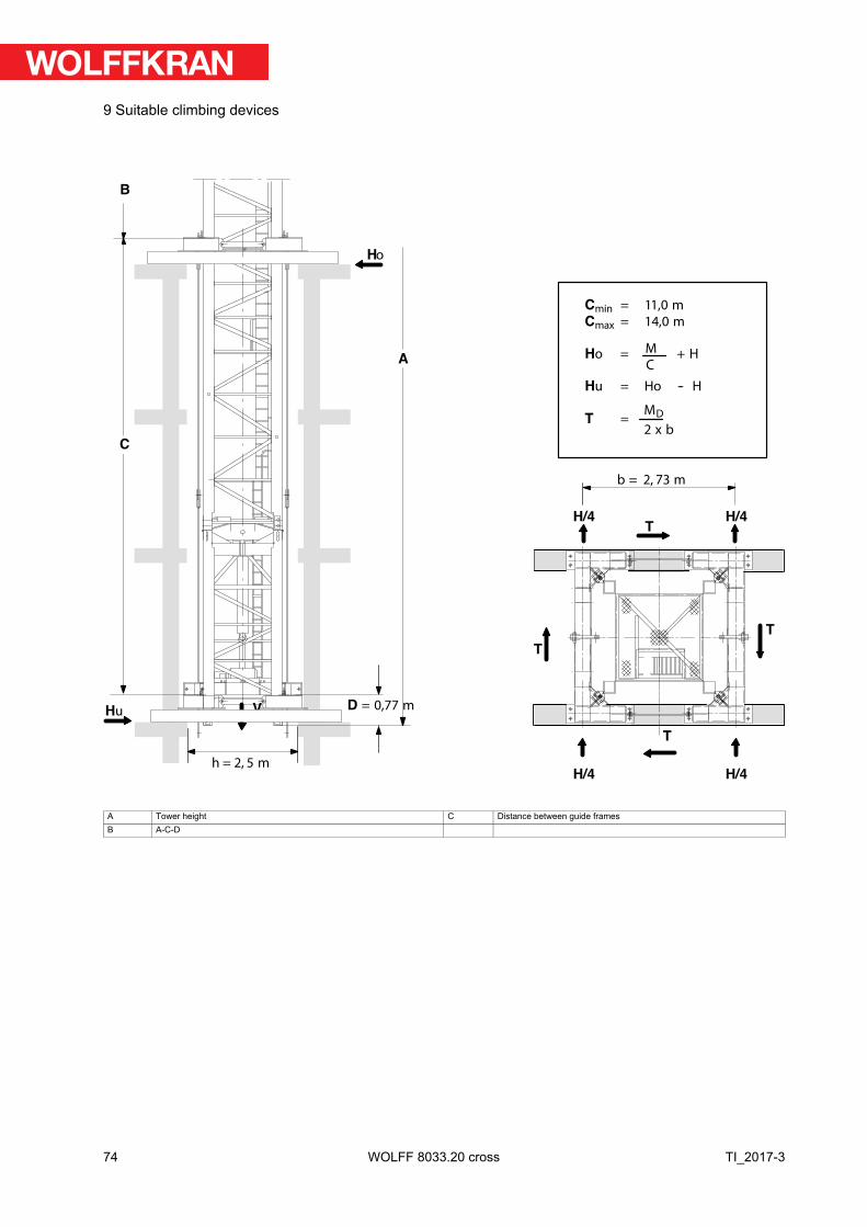
Cmin = 11,0 m
Cmax = 14,0 m
Ho = + H
Hu = Ho -- H
T =
A Tower height C Distance between guide framesB A-C-D
74
9 Suitable climbing devices
TI_2017-3WOLFF 8033.20 cross
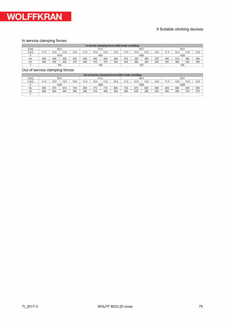
In service clamping forcesIn service clamping forces [kN] inside a building
A [m] 55.5 51.0 46.5 42.0C [m] 11.0 12.0 13.0 14.0 11.0 12.0 13.0 14.0 11.0 12.0 13.0 14.0 11.0 12.0 13.0 14.0
V 1510 1481 1453 1425Ho 530 490 450 420 500 460 430 400 470 430 400 370 450 410 380 350Hu 480 430 400 370 450 410 370 340 420 380 350 320 400 360 330 300T 100 100 100 100
Out of service clamping forcesOut of service clamping forces [kN] inside a building
A [m] 55.5 51.0 46.5 42.0C [m] 11.0 12.0 13.0 14.0 11.0 12.0 13.0 14.0 11.0 12.0 13.0 14.0 11.0 12.0 13.0 14.0
V 1293 1265 1236 1208Ho 950 870 810 750 840 770 710 660 730 670 620 580 640 580 540 500Hu 680 600 540 480 580 510 450 400 490 430 380 330 400 350 310 270T - - - -
75
9 Suitable climbing devices
TI_2017-3 WOLFF 8033.20 cross
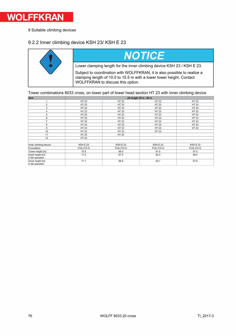
9.2.2 Inner climbing device KSH 23/ KSH E 23
!NOTICE
Lower clamping length for the inner climbing device KSH 23 / KSH E 23.
Subject to coordination with WOLFFKRAN, it is also possible to realize aclamping length of 10.0 to 15.5 m with a lower tower height. ContactWOLFFKRAN to discuss this option.
Tower combinations 8033 cross, on lower part of tower head section HT 23 with inner climbing deviceItem Jib length 30 m 80 m
1 HT 23 HT 23 HT 23 HT 232 HT 23 HT 23 HT 23 HT 233 HT 23 HT 23 HT 23 HT 234 HT 23 HT 23 HT 23 HT 235 HT 23 HT 23 HT 23 HT 236 HT 23 HT 23 HT 23 HT 237 HT 23 HT 23 HT 23 HT 238 HT 23 HT 23 HT 23 HT 239 HT 23 HT 23 HT 23 HT 23
10 HT 23 HT 23 HT 2311 HT 23 HT 2312 HT 23
inner climbing device KSH E 23 KSH E 23 KSH E 23 KSH E 23Foundation FUA 210 G FUA 210 G FUA 210 G FUA 210 GTower height [m] 70.5 66.0 61.5 57.0Hook height [m]2 fall operation
71.5 67.0 62.5 58.0
Hook height [m]4 fall operation
71.1 66.6 62.1 57.6
76
9 Suitable climbing devices
TI_2017-3WOLFF 8033.20 cross
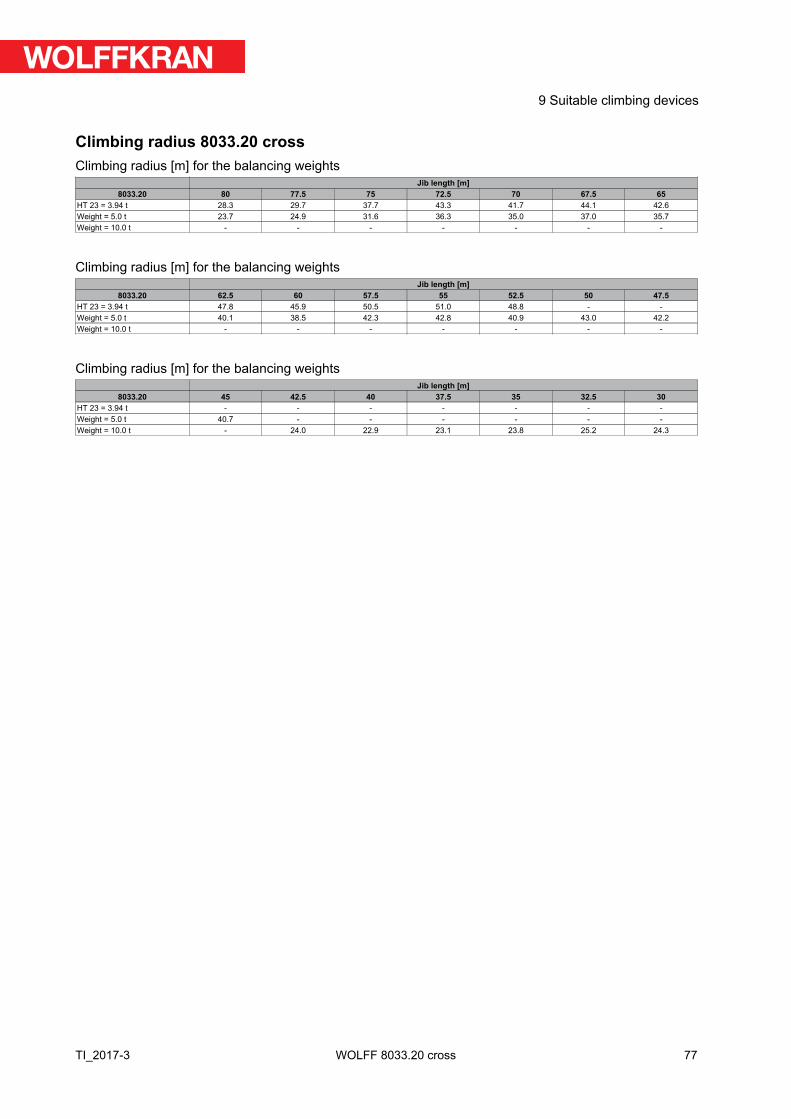
Climbing radius 8033.20 crossClimbing radius [m] for the balancing weights
Jib length [m]8033.20 80 77.5 75 72.5 70 67.5 65
HT 23 = 3.94 t 28.3 29.7 37.7 43.3 41.7 44.1 42.6Weight = 5.0 t 23.7 24.9 31.6 36.3 35.0 37.0 35.7Weight = 10.0 t - - - - - - -
Climbing radius [m] for the balancing weightsJib length [m]
8033.20 62.5 60 57.5 55 52.5 50 47.5HT 23 = 3.94 t 47.8 45.9 50.5 51.0 48.8 - -Weight = 5.0 t 40.1 38.5 42.3 42.8 40.9 43.0 42.2Weight = 10.0 t - - - - - - -
Climbing radius [m] for the balancing weightsJib length [m]
8033.20 45 42.5 40 37.5 35 32.5 30HT 23 = 3.94 t - - - - - - -Weight = 5.0 t 40.7 - - - - - -Weight = 10.0 t - 24.0 22.9 23.1 23.8 25.2 24.3
77
9 Suitable climbing devices
TI_2017-3 WOLFF 8033.20 cross
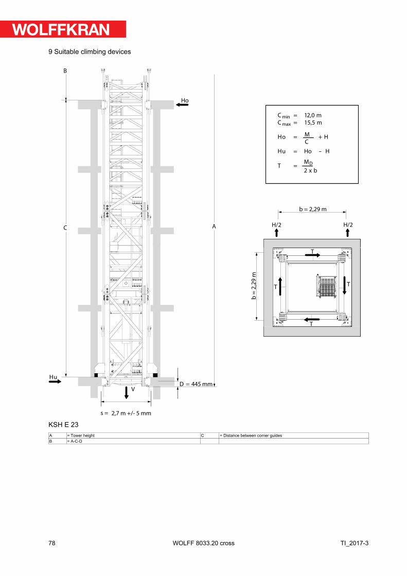
M
C
M
2 x b
D
C
B
A
Hu
Ho
T
TT
V
T
H/2
s =
D = 445 mm
Cmin = 12,0 m
Cmax = 15,5 m
Ho = + H
Hu = Ho -- H
T =
2,7 m +/- 5 mm
b = 2,29 m
H/2
b =
2,2
9 m
KSH E 23A = Tower height C = Distance between corner guidesB = A-C-D
78
9 Suitable climbing devices
TI_2017-3WOLFF 8033.20 cross
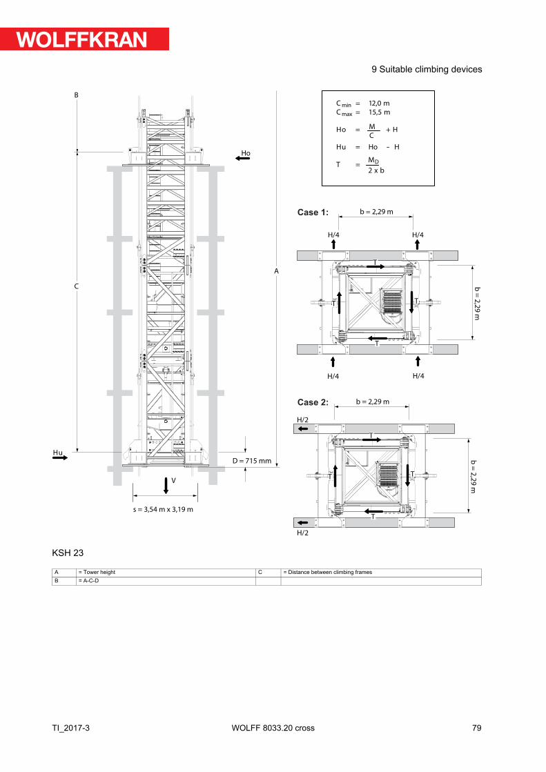
V
s = 3,54 m x 3,19 m
D = 715 mm
C
B
Hu
Ho
A
M
C
M
2 x b
D
Cmin = 12,0 m
Cmax = 15,5 m
Ho = + H
Hu = Ho -- H
T =
b = 2,29 m
H/4
H/4
H/4
H/4
T
TT
T
b =
2,2
9 m
b = 2,29 m
H/2
H/2
T
TT
T
b =
2,2
9 m
Case 1:
Case 2:
KSH 23
A = Tower height C = Distance between climbing framesB = A-C-D
79
9 Suitable climbing devices
TI_2017-3 WOLFF 8033.20 cross
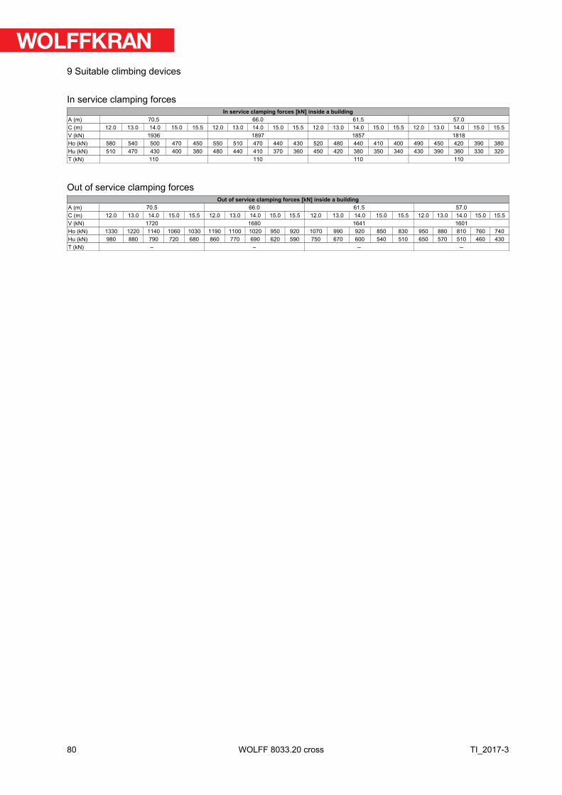
In service clamping forcesIn service clamping forces [kN] inside a building
A (m) 70.5 66.0 61.5 57.0C (m) 12.0 13.0 14.0 15.0 15.5 12.0 13.0 14.0 15.0 15.5 12.0 13.0 14.0 15.0 15.5 12.0 13.0 14.0 15.0 15.5V (kN) 1936 1897 1857 1818Ho (kN) 580 540 500 470 450 550 510 470 440 430 520 480 440 410 400 490 450 420 390 380Hu (kN) 510 470 430 400 380 480 440 410 370 360 450 420 380 350 340 430 390 360 330 320T (kN) 110 110 110 110
Out of service clamping forcesOut of service clamping forces [kN] inside a building
A (m) 70.5 66.0 61.5 57.0C (m) 12.0 13.0 14.0 15.0 15.5 12.0 13.0 14.0 15.0 15.5 12.0 13.0 14.0 15.0 15.5 12.0 13.0 14.0 15.0 15.5V (kN) 1720 1680 1641 1601Ho (kN) 1330 1220 1140 1060 1030 1190 1100 1020 950 920 1070 990 920 850 830 950 880 810 760 740Hu (kN) 980 880 790 720 680 860 770 690 620 590 750 670 600 540 510 650 570 510 460 430T (kN) – – – –
80
9 Suitable climbing devices
TI_2017-3WOLFF 8033.20 cross
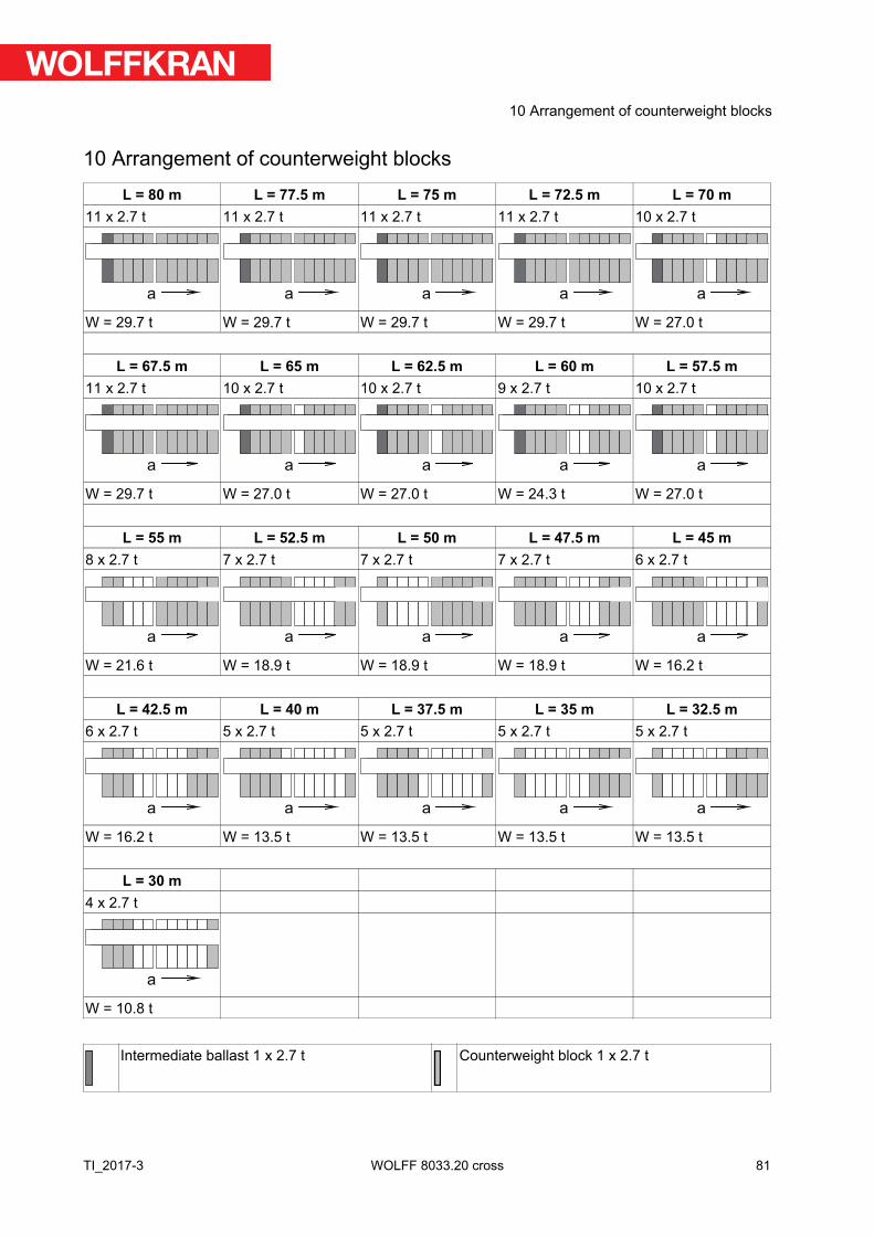
10 Arrangement of counterweight blocks
L = 80 m L = 77.5 m L = 75 m L = 72.5 m L = 70 m11 x 2.7 t 11 x 2.7 t 11 x 2.7 t 11 x 2.7 t 10 x 2.7 t
a a a a a
W = 29.7 t W = 29.7 t W = 29.7 t W = 29.7 t W = 27.0 t
L = 67.5 m L = 65 m L = 62.5 m L = 60 m L = 57.5 m11 x 2.7 t 10 x 2.7 t 10 x 2.7 t 9 x 2.7 t 10 x 2.7 t
a a a a a
W = 29.7 t W = 27.0 t W = 27.0 t W = 24.3 t W = 27.0 t
L = 55 m L = 52.5 m L = 50 m L = 47.5 m L = 45 m8 x 2.7 t 7 x 2.7 t 7 x 2.7 t 7 x 2.7 t 6 x 2.7 t
a a a a a
W = 21.6 t W = 18.9 t W = 18.9 t W = 18.9 t W = 16.2 t
L = 42.5 m L = 40 m L = 37.5 m L = 35 m L = 32.5 m6 x 2.7 t 5 x 2.7 t 5 x 2.7 t 5 x 2.7 t 5 x 2.7 t
a a a a a
W = 16.2 t W = 13.5 t W = 13.5 t W = 13.5 t W = 13.5 t
L = 30 m4 x 2.7 t
a
W = 10.8 t
Intermediate ballast 1 x 2.7 t Counterweight block 1 x 2.7 t
81
10 Arrangement of counterweight blocks
TI_2017-3 WOLFF 8033.20 cross
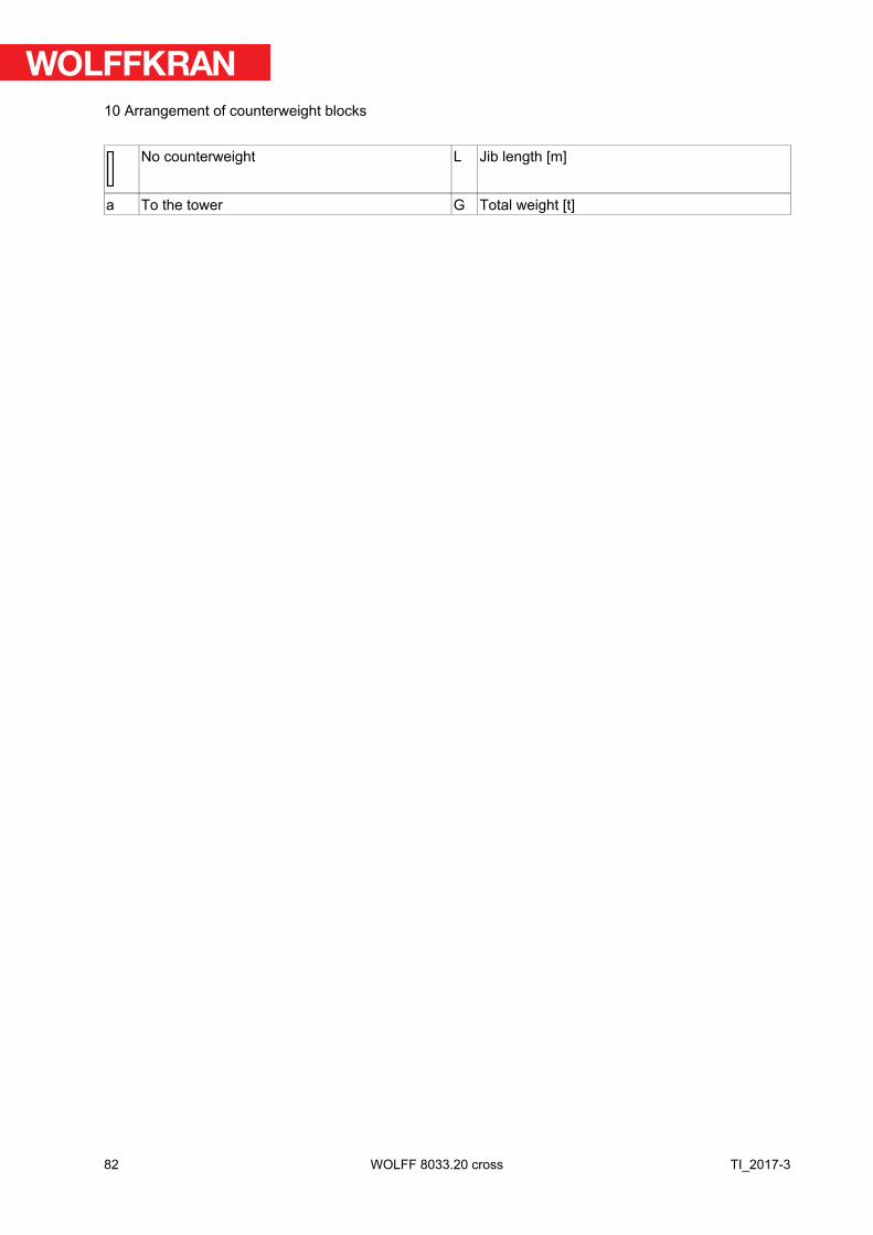
No counterweight L Jib length [m]
a To the tower G Total weight [t]
82
10 Arrangement of counterweight blocks
TI_2017-3WOLFF 8033.20 cross

WOLFFKRAN GroupHeadquarter international:
WOLFFKRAN AGBaarermattstraße 6
CH-6300 Zug
Switzerland
Phone +41 41 766 85 00
Fax +41 41 766 85 99
Manufacturing:
WOLFFKRAN GmbHAustraße 72
D-74076 Heilbronn
Germany
Phone + 49 7131 9815 0
Fax + 49 7131 9815 355
WOLFFKRAN Werk Brandenburg GmbHFrederik-Ipsen-Straße 5
D-15926 Luckau OT Alterno
Germany
Phone + 49 35456 674 0
Fax + 49 35456 674 200
www.wolffkran.com