Embed Size (px)
Citation preview
SLHC-PP – WP7Critical Components for Injector Upgrade
Plasma Generator – CERN, DESY, STFC-RALLinac4 2MHz RF sourceThermal ModelingGas Measurement and ModelingSPL test area
Low Level RF – CEA, CERN, INFNb=0.5 sc cavitiesRF measurement systemRF simulation

The Linac4 source
Spectrometer magnets
Electron dump
Ferrites
Confinement magnets
Collar and plasma feedthrough

Thermal model of the Linac4 source.
Assumptions made:
•All power (100kW peak) is delivered into the plasma (worst case).
•This power is delivered uniformly to the internal walls of the source. (No plasma modeling is included).
•Outer cooling is ambient air cooling and radiation (low).
•Internal surfaces in vacuum are radiation cooled.

At Linac4 power:
•Collar temperature is high, (assumptions lead to high power to the collar, which is thermally isolated).
•Other temperatures are serviceable for the materials used. Plastic magnet cage gives a low thermal conductivity to outside.
At SPL power:
•Several materials above their service temperature. All magnets/ferrites above Curie temperature.
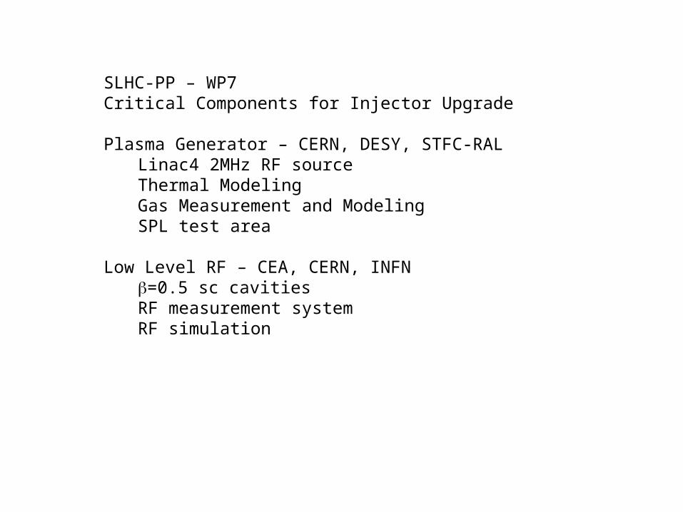
Deliverables
•7.1.1 Finite element thermal study of the Linac4 design source at the final duty factor Report M12 Deliverable report being written.
•Next stages to progress to milestone:
•Introduce cooling systems in critical and accessible regions.
•New materials (AlN for chamber, and similar cooling sleeve – a la SNS).
•Critical point is the collar and plasma electrodes.
•7.1.2 Design of a high duty factor plasma generator Report M18 Follows on from milestone.
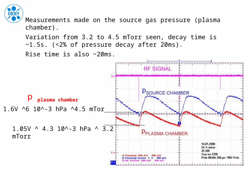
1.6V ^6 10^-3 hPa ^4.5 mTorr
1.05V ^ 4.3 10^-3 hPa ^ 3.2 mTorr
p plasma chamber
Measurements made on the source gas pressure (plasma chamber).
Variation from 3.2 to 4.5 mTorr seen, decay time is ~1.5s. (<2% of pressure decay after 20ms).
Rise time is also ~20ms.

0.0001
0.001
0.01
0.1
1
0 0.05 0.1 0.15 0.2 0.25 0.3 0.35 0.4
Pres
sure
(tor
r)
Time (s)
injection chamber 8mLplama chamber 235mLpenning chamber 20mLExtraction chamberMeasured Pressure
Model based on conductance between different volumes.
Gives good agreement under certain assumptions.
Measured data and model

• PhD student– First 50 Hz operation on CERN’s Linac-4 test stand of
the non-cesiated Desy RF volume H- source.– Computing gas flow through the source from pulsed gas
injection, to continuous flow.

SLHC-Plasma Chamber test rooms 357-R-005 & 357-R-011
Low Level RF Task 7.2
•Preparation of the cavities, coupler and cryostats for tests.
•Preparation of the measurement systems.
•Simulation techniques for the RF for SPL.

Objective of the tests:
Study and development of a correction algorithm of the Lorentz Force Detuning able to limit the variation of the phase during the beam pulse in order to achieve the required field stability (amplitude and phase) with limited power margin. Implementation and measurement in pulsed mode on a real sc cavity
Measurement of the Lorentz Force Detuning in CW mode
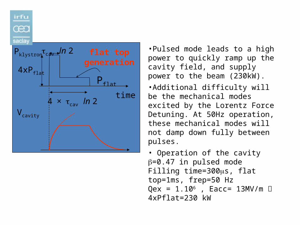
Pklystron
Pflat
4xPflat
tcav ln 2
4 × tcav ln 2
flat topgeneration
time
Vcavity
•Pulsed mode leads to a high power to quickly ramp up the cavity field, and supply power to the beam (230kW).
•Additional difficulty will be the mechanical modes excited by the Lorentz Force Detuning. At 50Hz operation, these mechanical modes will not damp down fully between pulses.
• Operation of the cavity b=0.47 in pulsed modeFilling time=300ms, flat top=1ms, frep=50 HzQex = 1.106 , Eacc= 13MV/m 4xPflat=230 kW

From CARE/HIPPI (FP6)
704 MHz 5cellsbeta=0.5 cavity (SPL requires 0.65, 1)Valid for stability tests.
after welding of LHe tank
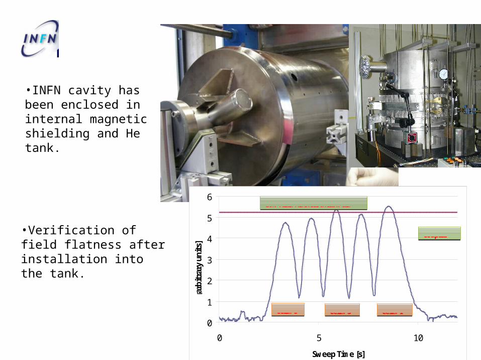
•Verification of field flatness after installation into the tank.
0
1
2
3
4
5
6
0 5 10
Sweep Time [s]
[arb
itra
ry u
nits
]
Coupler
Cell # 5 Cell # 3 Cell # 1
10% Field Flatness after weld
•INFN cavity has been enclosed in internal magnetic shielding and He tank.

•CryHoLab (horizontal cryostat) has cavity installed.
•Ready for connection to the 700MHz high power klystron and fitted with power coupler.
•Klystron tested, 1.2MW cw achieved. Can work at 50Hz, 2ms pulsed mode, reduced power (HV limitations at the moment).
•Coupler is built, and under processing towards full power for SPL.
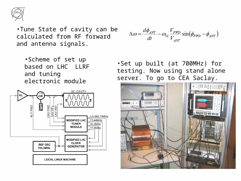
•Tune State of cavity can be calculated from RF forward and antenna signals.
•Scheme of set up based on LHC LLRF and tuning electronic module
•Set up built (at 700MHz) for testing. Now using stand alone server. To go to CEA Saclay.

Vectormodulator
Vectormodulator
Vectormodulator
Vectormodulator
LLRF
VectorSUM
Klystron
Feedback
Example RF layout for SPL
4 cavities per klystron.
Simulate how this system behaves with LFD (but no active LFD compensation).
Piezo

0.5 1 1.5 2 2.5
-10
-5
0
5
10
time (ms)
Vec
tor
Sum
pha
se (
deg)
0.8 1 1.2 1.4 1.6 1.8 2 2.2 2.4 2.6
-6
-4
-2
0
2
4
6
8
time (ms)
cavi
ty v
olta
ge p
hase
(de
g)
1.4 1.6 1.8 2 2.2 2.4 2.6
82
84
86
88
90
92
time (ms)
Vec
tor
Sum
am
plitu
de (
MV
)
Vector Sum
1.2 1.4 1.6 1.8 2 2.2 2.4 2.6 2.8
19
19.5
20
20.5
21
21.5
22
22.5
23
23.5
24
time (ms)
cavi
ty v
olta
ge a
mpl
itude
(M
V)
Cavities
±3% ±4°
Example (to illustrate what the simulation can calculate) of how the system behaves with different LFD constants per cavity.

Deliverables
•7.2.1 In depth characterisation of the two tuners plus cavities developed in the frame of the “HIPPI” JRA , FP6 In order to properly achieve this deliverable, more time is required. 6 months to complete assembly, 3 months for testing. Second cavity will also require additional 3 months.
•7.2.2 Design of RF system architecture including modeling of RF components, simulation of the RF system and simulation of beam dynamics of the full Linac; RF system and high power modulator specifications R M18Requires input from the deliverable above.
•7.2.3 Production of a prototype electronic system and other elements for a full system demonstration; Definition of demonstration procedure P M30 Work has been started and progressed well in order to make a measurement system for 7.2.1
Summary
•Plasma Generator/SourceThermal modeling and design started. Gas calculations started.First deliverables are within reach.
•LL RFTest stand is ready (Klystron, cryostat…)First deliverable being rescheduled following HIPPI.Confident we can achieve the program.

Plasma Spectral analysis & temperature measurement
Linac-4 ion-source
SPL-plasma Chamber