Embed Size (px)
Citation preview
Slide 1
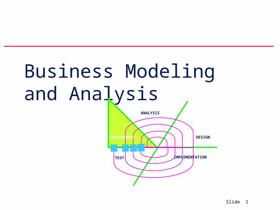
Business Modeling and Analysis
REQUIREMENT
ANALYSIS
DESIGN
IMPLEMENTATIONTEST
Slide 2
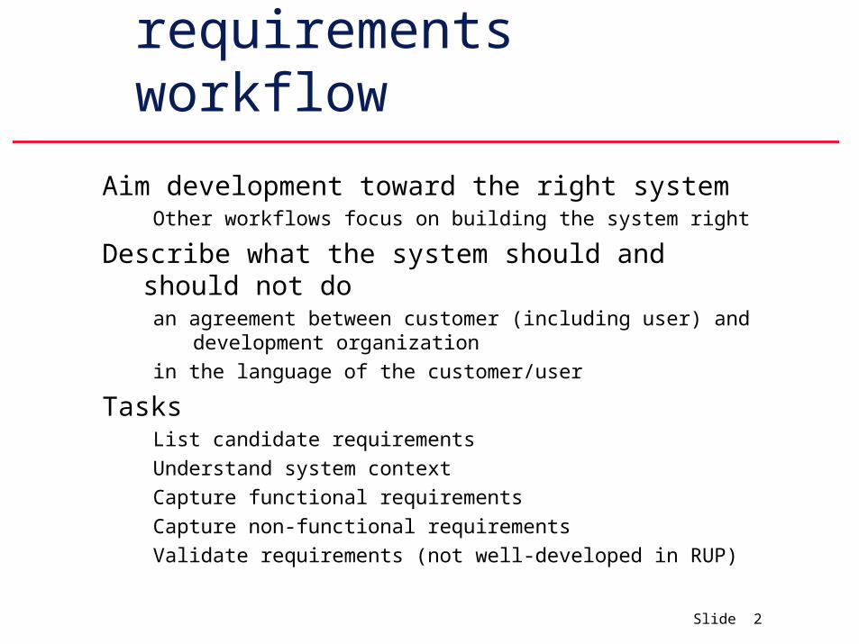
Purpose of requirements workflow
Aim development toward the right systemOther workflows focus on building the system right
Describe what the system should and should not doan agreement between customer (including user) and development
organization
in the language of the customer/user
TasksList candidate requirements
Understand system context
Capture functional requirements
Capture non-functional requirements
Validate requirements (not well-developed in RUP)
Slide 3
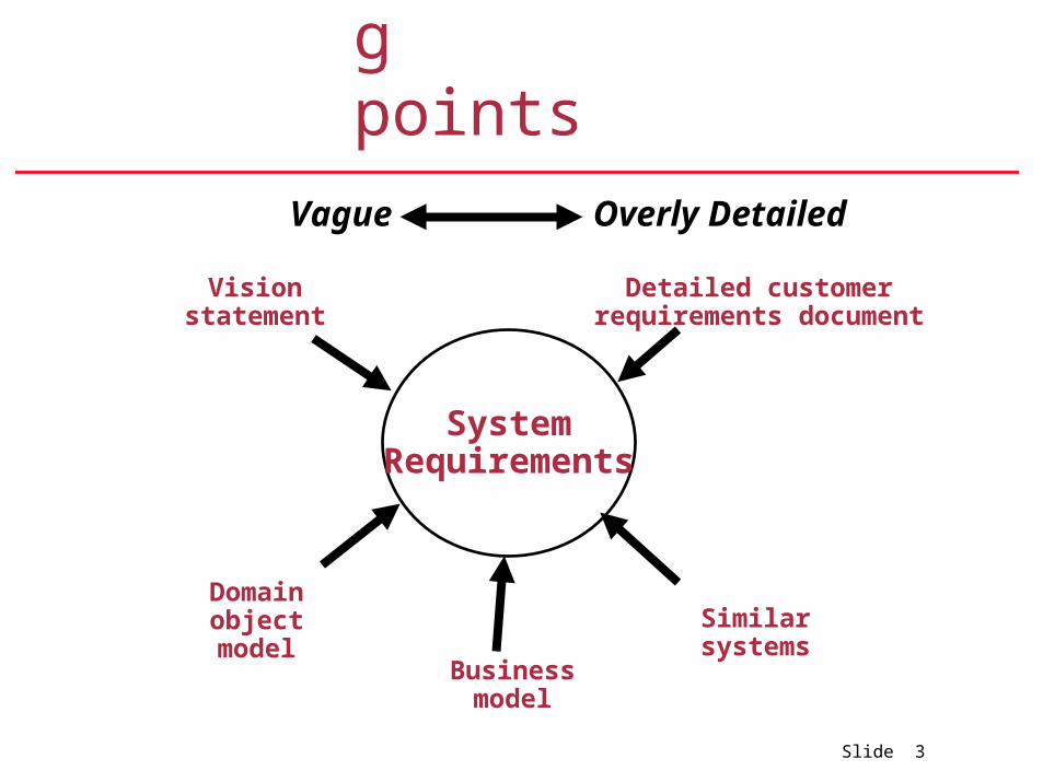
Starting points
SystemRequirements
Detailed customer requirements document
Business model
Domain object model
Vision statement
Similar systems
Vague Overly Detailed
Slide 4
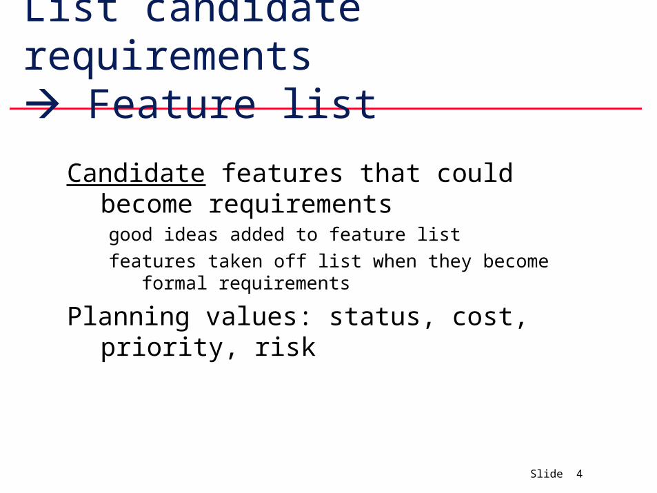
List candidate requirements Feature list
Candidate features that could become requirementsgood ideas added to feature list
features taken off list when they become formal requirements
Planning values: status, cost, priority, risk
Slide 5
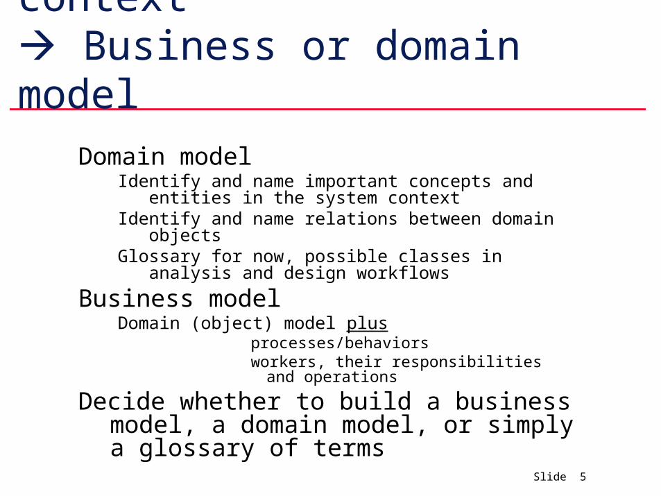
Understand system context Business or domain model
Domain modelIdentify and name important concepts and entities in the
system contextIdentify and name relations between domain objectsGlossary for now, possible classes in analysis and design
workflows
Business modelDomain (object) model plus
processes/behaviors workers, their responsibilities and operations
Decide whether to build a business model, a domain model, or simply a glossary of terms
Slide 6
Capture functional requirements Use cases
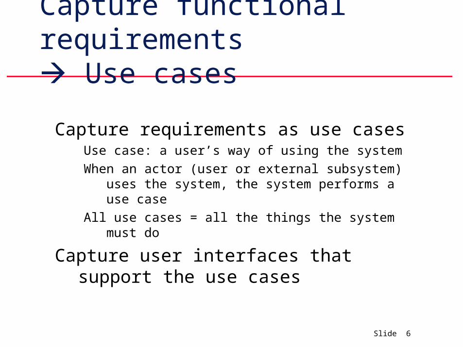
Capture requirements as use casesUse case: a user’s way of using the system
When an actor (user or external subsystem) uses the system, the system performs a use case
All use cases = all the things the system must do
Capture user interfaces that support the use cases
Slide 7
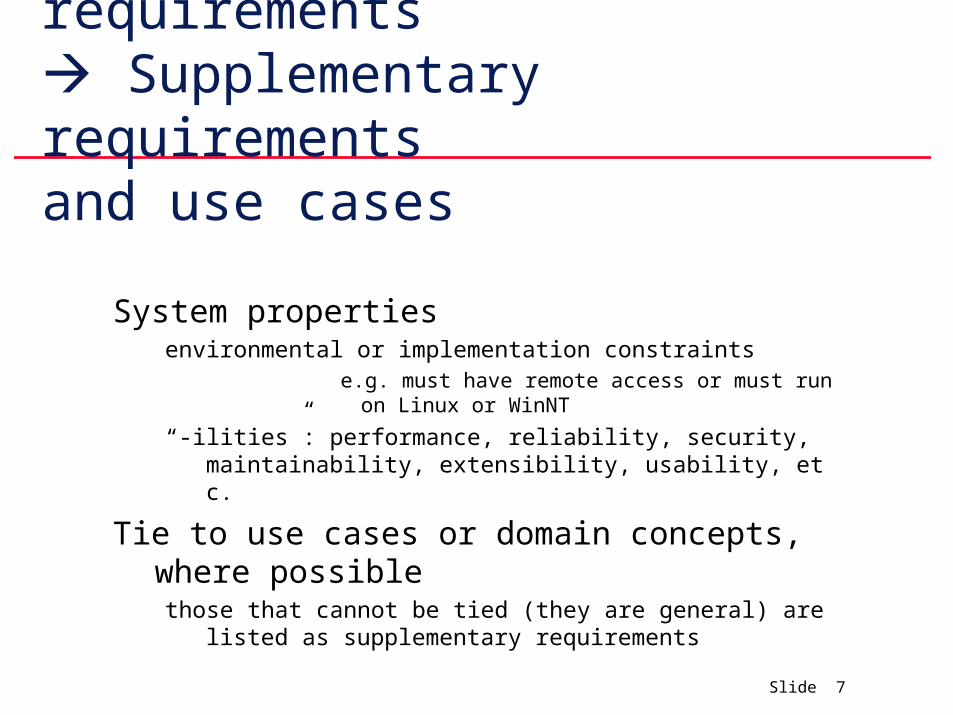
Capture non-functional requirements Supplementary requirementsand use cases
System propertiesenvironmental or implementation constraints
e.g. must have remote access or must run on Linux or WinNT
“-ilities”: performance, reliability, security, maintainability, extensibility, usability, etc.
Tie to use cases or domain concepts, where possiblethose that cannot be tied (they are general) are listed as supplem
entary requirements
Slide 8
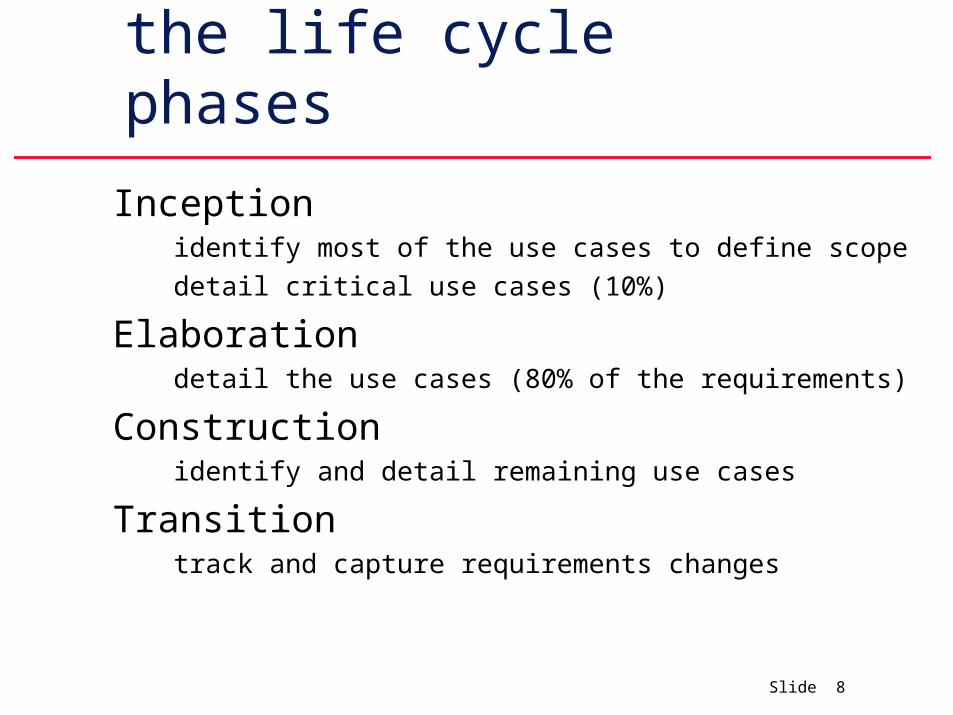
Requirements in the life cycle phases
Inceptionidentify most of the use cases to define scope
detail critical use cases (10%)
Elaborationdetail the use cases (80% of the requirements)
Constructionidentify and detail remaining use cases
Transitiontrack and capture requirements changes
Slide 9
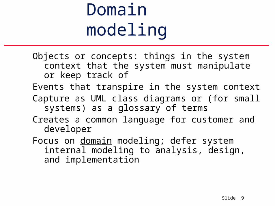
Domain modeling
Objects or concepts: things in the system context that the system must manipulate or keep track of
Events that transpire in the system contextCapture as UML class diagrams or (for small
systems) as a glossary of termsCreates a common language for customer and
developerFocus on domain modeling; defer system internal
modeling to analysis, design, and implementation
Slide 10
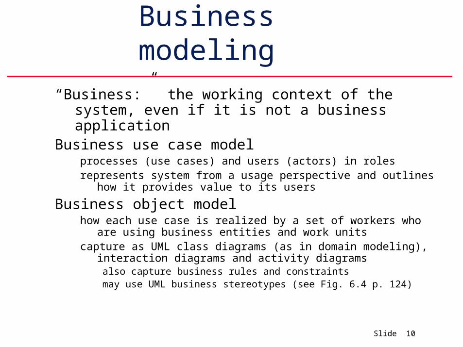
Business modeling
“Business:” the working context of the system, even if it is not a business application
Business use case modelprocesses (use cases) and users (actors) in rolesrepresents system from a usage perspective and outlines how it provides
value to its users
Business object modelhow each use case is realized by a set of workers who are using business
entities and work unitscapture as UML class diagrams (as in domain modeling), interaction
diagrams and activity diagramsalso capture business rules and constraintsmay use UML business stereotypes (see Fig. 6.4 p. 124)
Slide 11
“Traditional” requirements capture
Slide 12
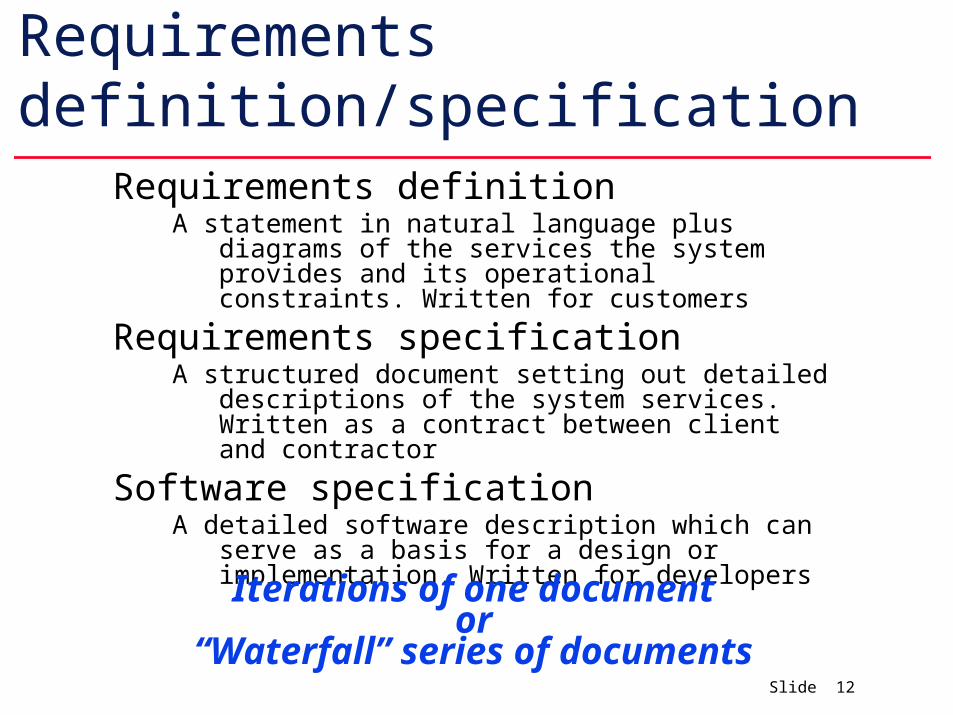
Requirements definition/specificationRequirements definition
A statement in natural language plus diagrams of the services the system provides and its operational constraints. Written for customers
Requirements specificationA structured document setting out detailed descriptions of the
system services. Written as a contract between client and contractor
Software specificationA detailed software description which can serve as a basis for
a design or implementation. Written for developers
Iterations of one documentor
“Waterfall” series of documents
Slide 13
Business Engineering
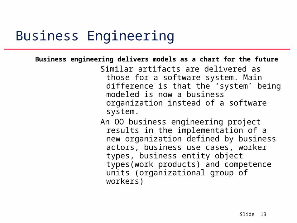
Business engineering delivers models as a chart for the future
Similar artifacts are delivered as those for a software system. Main difference is that the ‘system’ being modeled is now a business organization instead of a software system.
An OO business engineering project results in the implementation of a new organization defined by business actors, business use cases, worker types, business entity object types(work products) and competence units (organizational group of workers)
Slide 14
Business Models
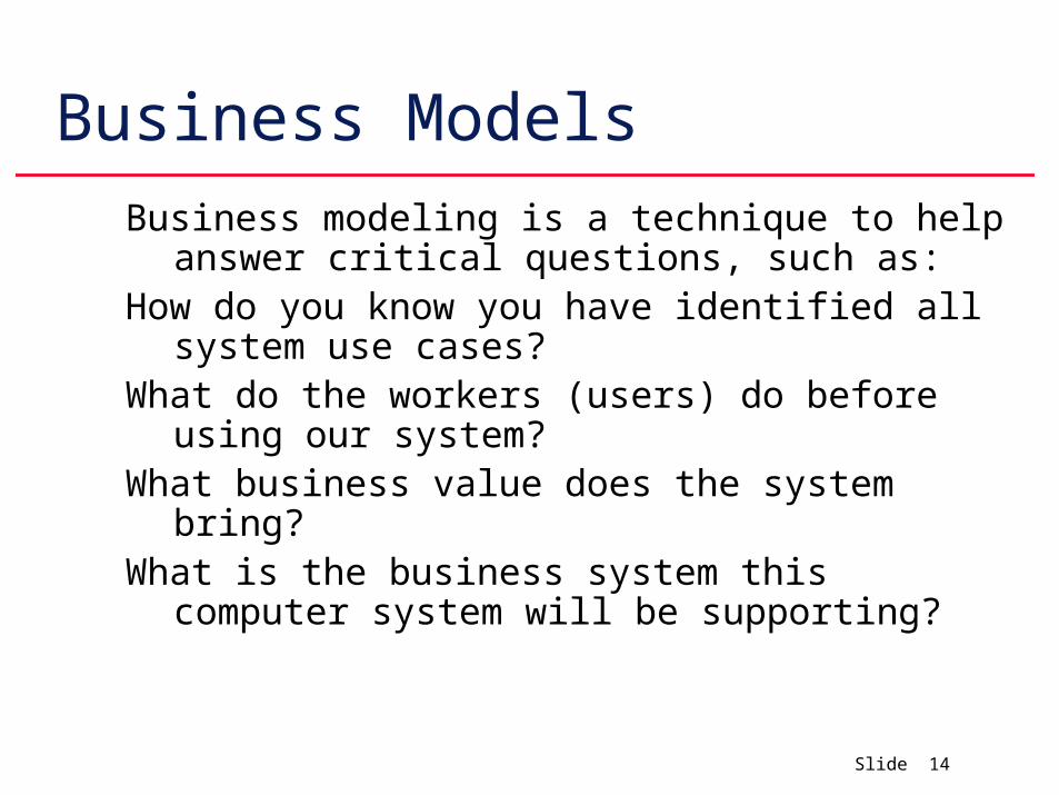
Business modeling is a technique to help answer critical questions, such as:
How do you know you have identified all system use cases?
What do the workers (users) do before using our system?
What business value does the system bring?What is the business system this computer system
will be supporting?
Slide 15
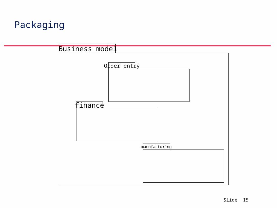
Packaging
Business model
Order entry
finance
manufacturing
Slide 16
The Business Object Model DescriptionThe Business Object Model work product identifies objects of importance
to a business and documents the relationships between them in terms of responsibilities and behavior.
Its emphasizes the roles performed in the business area and their active responsibilities.
It uses a subset of notation from the Unified Modeling Language (UML).
The Business Object Model brings the notions of structure and behavior together.
It is a bridging work product that articulates business concerns in a way that is similar to methods of software development while retaining a purely business content.
It is a consolidation of what is known about the area of business concern expressed in terms of objects, attributes, and responsibilities.
A Business Object Model is not a “model of business objects.” It is an “object model of the business.”
The difference is a matter of perspective.
The term “business objects” connotes the part of a software solution that directly represents items of interest to business.
The software domain is associated with the scope of a planned implementation.
This implementation-free view of the software space is the subject of an analysis object model
Slide 17
The Business Object Model Purpose
The Business Object Model is positioned firmly on the bridge between the world of business and the world of information systems development.
It explores the essence of business area knowledge in a way that provides a transition from thinking about business issues to thinking about software applications.
Its creation is a way of verifying requirements to be enabled or supported by the information system to be built.
Agreement between business object definitions and relationships, and the names for the objects and relationships permits business area knowledge to be represented in a precise manner that can be understood and validated by business area experts.
In addition, the Business Object Model Helps to scope what is inside and outside the specific application being developed. The boundaries of the application are explored through an object view of the business area. Can be reused by many development projects.
To the extent that it is it free of design details and is also free of application boundaries, a good Business Object Model is a key asset that a company can build, maintain, and reuse in many applications within the business area
Slide 18
Business Object Model
A Business Object Model is complete when it reflects all important business concepts within the intended scope as specified by the classified business terms.
A quality Business Object Model is one in which:The names of object types accurately reflect either concepts in the business area
or abstractions that structure the model.
Class names are appropriate. Names should convey intent. Be suspicious of names such as Controller and Manager as these often indicate a centralization of control.
No design artifacts are present.
Slide 19
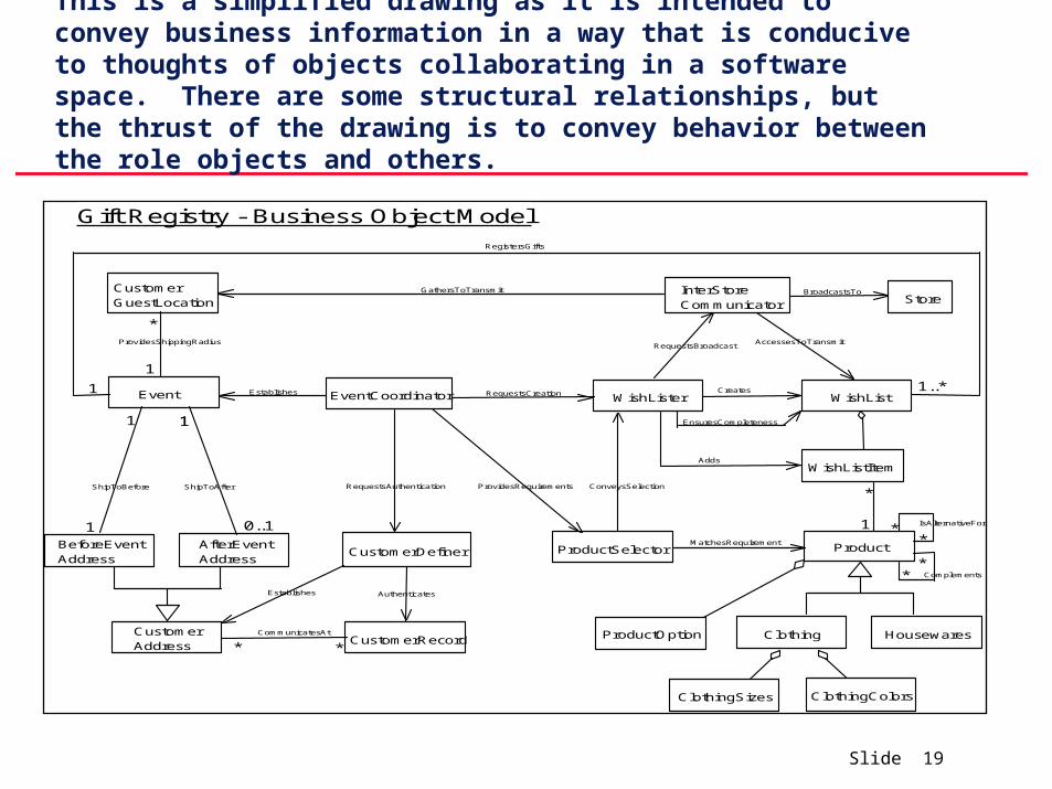
This is a simplified drawing as it is intended to convey business information in a way that is conducive to thoughts of objects collaborating in a software space. There are some structural relationships, but the thrust of the drawing is to convey behavior between the role objects and others.
Gift Registry - Business Object Model
*
1..*WishLister
Product
Clothing HousewaresProductOption
CustomerDefiner
EventCoordinator
ProductSelector
WishList
WishListItem
InterStoreCommunicator
**
** Complements
IsAlternativeFor1
Creates
RequestsBroadcastAccessesToTransmit
CustomerAddress
BeforeEventAddress
AfterEventAddress
Event
CustomerGuestLocation Store
BroadcastsTo
MatchesRequirement
GathersToTransmit
CustomerRecordCommunicatesAt
Authenticates
ClothingSizes ClothingColors
Establishes RequestsCreation
ProvidesShippingRadius
Adds
RequestsAuthenticationShipToBefore ShipToAfter ProvidesRequirements ConveysSelection
RegistersGifts
EnsuresCompleteness
*
1
1
Establishes
1
1
1
0..1
1
* *
Slide 20
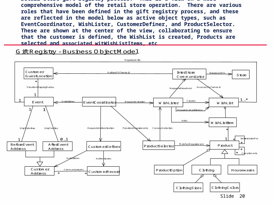
The following example is based on a business process model from a retail store gift registry process. This is a view on a more comprehensive model of the retail store operation. There are various roles that have been defined in the gift registry process, and these are reflected in the model below as active object types, such as EventCoordinator, WishLister, CustomerDefiner, and ProductSelector. These are shown at the center of the view, collaborating to ensure that the customer is defined, the WishList is created, Products are selected and associated witWishListItems, etc
Gift Registry - Business Object Model
*
1..*WishLister
Product
Clothing HousewaresProductOption
CustomerDefiner
EventCoordinator
ProductSelector
WishList
WishListItem
InterStoreCommunicator
**
** Complements
IsAlternativeFor1
Creates
RequestsBroadcastAccessesToTransmit
CustomerAddress
BeforeEventAddress
AfterEventAddress
Event
CustomerGuestLocation Store
BroadcastsTo
MatchesRequirement
GathersToTransmit
CustomerRecordCommunicatesAt
Authenticates
ClothingSizes ClothingColors
Establishes RequestsCreation
ProvidesShippingRadius
Adds
RequestsAuthenticationShipToBefore ShipToAfter ProvidesRequirements ConveysSelection
RegistersGifts
EnsuresCompleteness
*
1
1
Establishes
1
1
1
0..1
1
* *
Slide 21
UMLThe UML provides different diagrams. Each UML diagram provides a
different view of the business:use case diagrams describe the business context.activity diagrams describe behaviors in the business, or business
workflows.class diagrams describe the static structure in the business.interactions diagrams (sequence diagrams and collaboration
diagrams) describe the dynamic interactions between employees and things that they manipulate. Thus they indicate how the behaviors described in activity diagrams are realized.
Slide 22
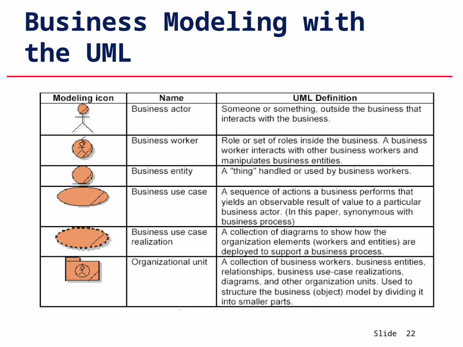
Business Modeling with the UML
Slide 23
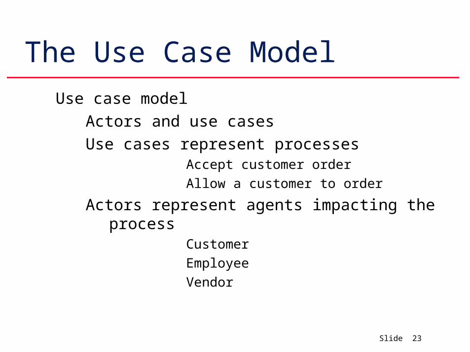
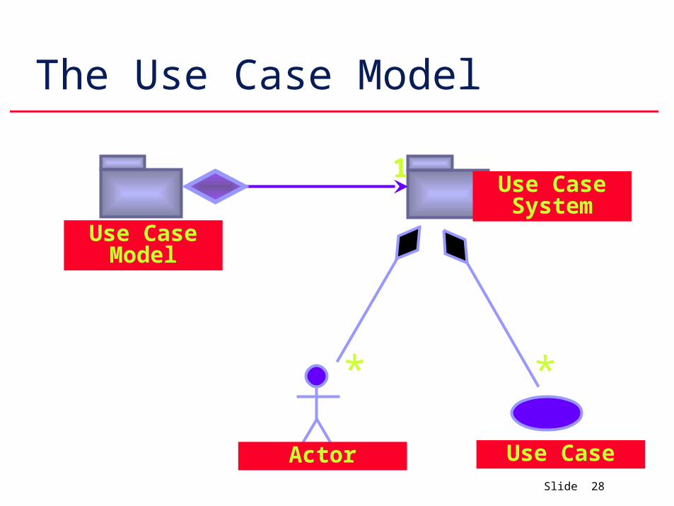
The Use Case Model
Use case model
Actors and use cases
Use cases represent processesAccept customer order
Allow a customer to order
Actors represent agents impacting the processCustomer
Employee
Vendor
Slide 24
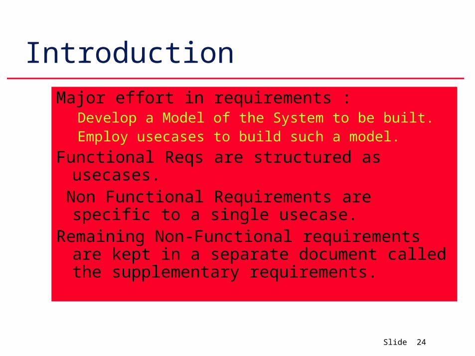
Introduction
Major effort in requirements :Develop a Model of the System to be built.Employ usecases to build such a model.
Functional Reqs are structured as usecases. Non Functional Requirements are specific to a
single usecase.Remaining Non-Functional requirements are kept in
a separate document called the supplementary requirements.
Slide 25
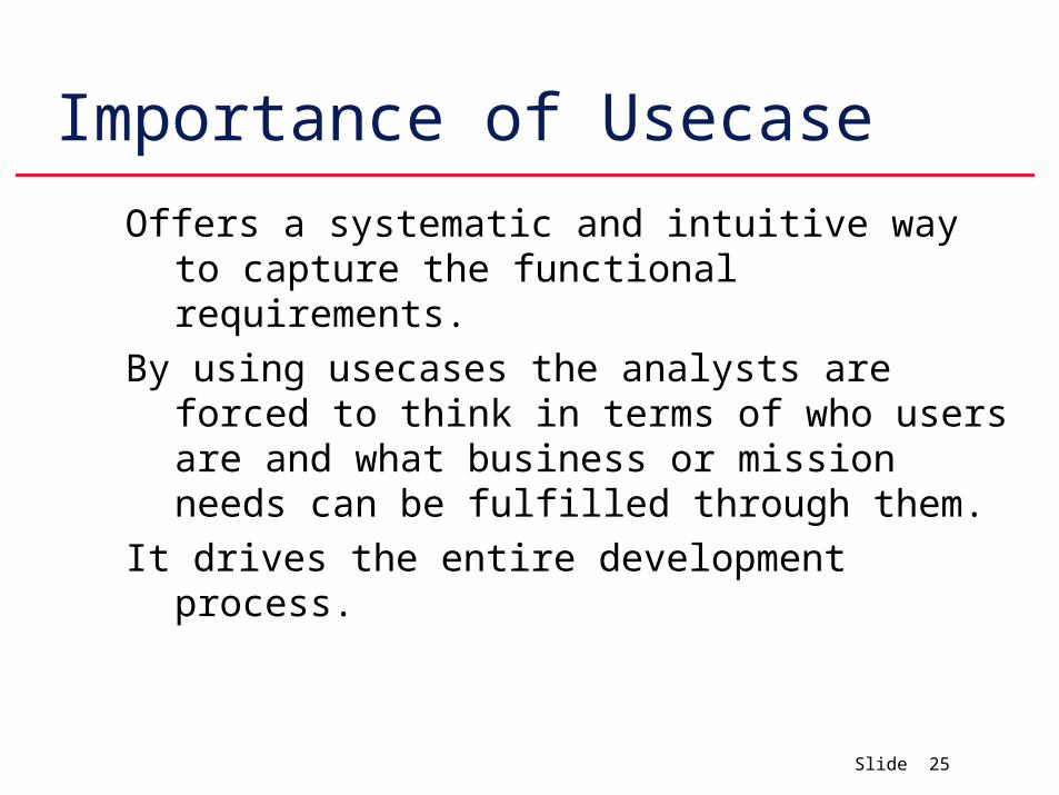
Importance of Usecase
Offers a systematic and intuitive way to capture the functional requirements.
By using usecases the analysts are forced to think in terms of who users are and what business or mission needs can be fulfilled through them.
It drives the entire development process.
Slide 26
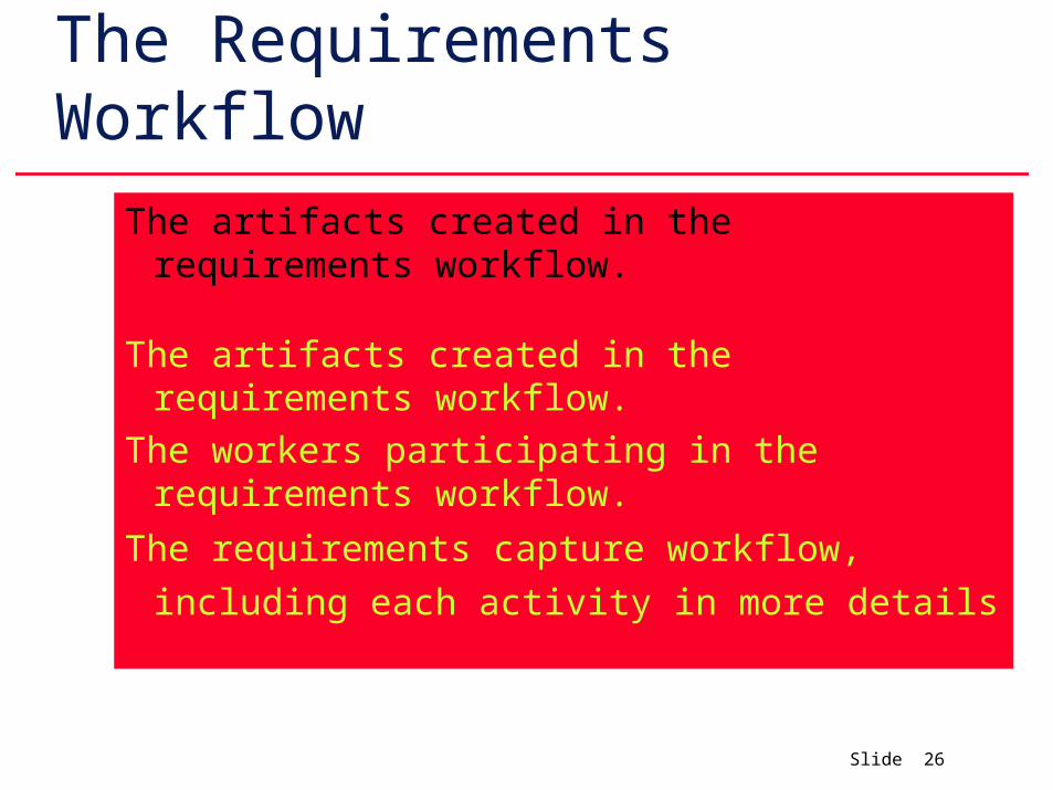
The Requirements Workflow
The artifacts created in the requirements workflow.
The artifacts created in the requirements workflow.
The workers participating in the requirements workflow.
The requirements capture workflow, including each
activity in more details
Slide 27
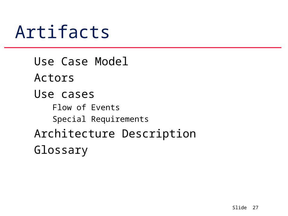
Artifacts
Use Case Model
Actors
Use casesFlow of Events
Special Requirements
Architecture Description
Glossary
Slide 28
The Use Case Model
* *
1
Use Case Model
Use Case System
Actor Use Case
Slide 29
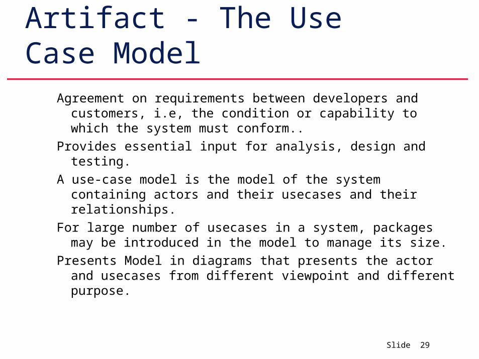
Artifact - The Use Case Model
Agreement on requirements between developers and customers, i.e, the condition or capability to which the system must conform..
Provides essential input for analysis, design and testing.
A use-case model is the model of the system containing actors and their usecases and their relationships.
For large number of usecases in a system, packages may be introduced in the model to manage its size.
Presents Model in diagrams that presents the actor and usecases from different viewpoint and different purpose.
Slide 30
Artifact - Actor
Parties outside the system that collaborate with the system
Often corresponds to workers in a business.
An actor plays one role for each case with it collaborates. Each time a specific user interacts with the system, the corresponding actor instance is playing the role.
An instance of an actor is thus a specific user interacting with the system.
Any entity that conforms to an actor can act as an instance of the actor.
Slide 31
Artifact - Actor
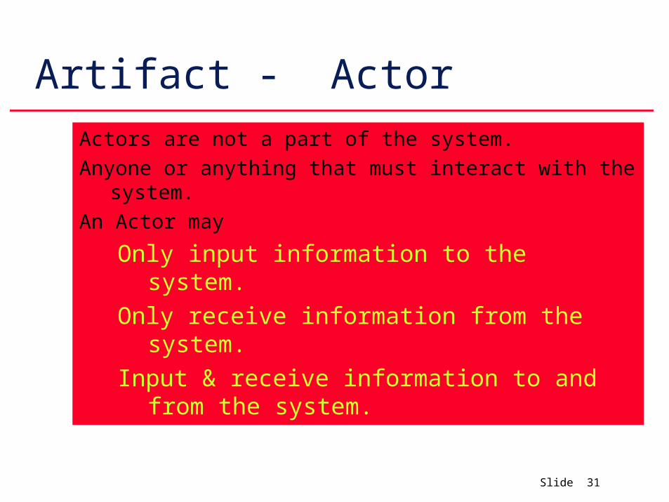
Actors are not a part of the system.
Anyone or anything that must interact with the system.
An Actor may
Only input information to the system.
Only receive information from the system.
Input & receive information to and from the system.
Slide 32
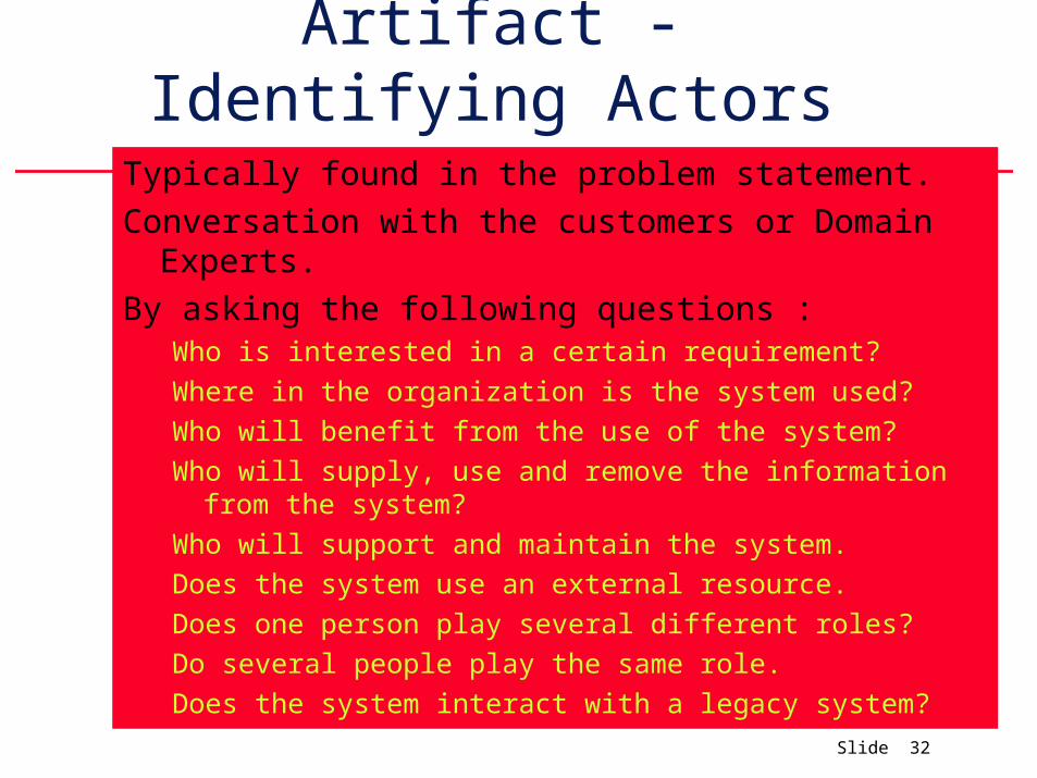
Artifact - Identifying Actors Typically found in the problem statement.
Conversation with the customers or Domain Experts.
By asking the following questions :Who is interested in a certain requirement?
Where in the organization is the system used?
Who will benefit from the use of the system?
Who will supply, use and remove the information from the system?
Who will support and maintain the system.
Does the system use an external resource.
Does one person play several different roles?
Do several people play the same role.
Does the system interact with a legacy system?
Slide 33
Artifact - Usecase
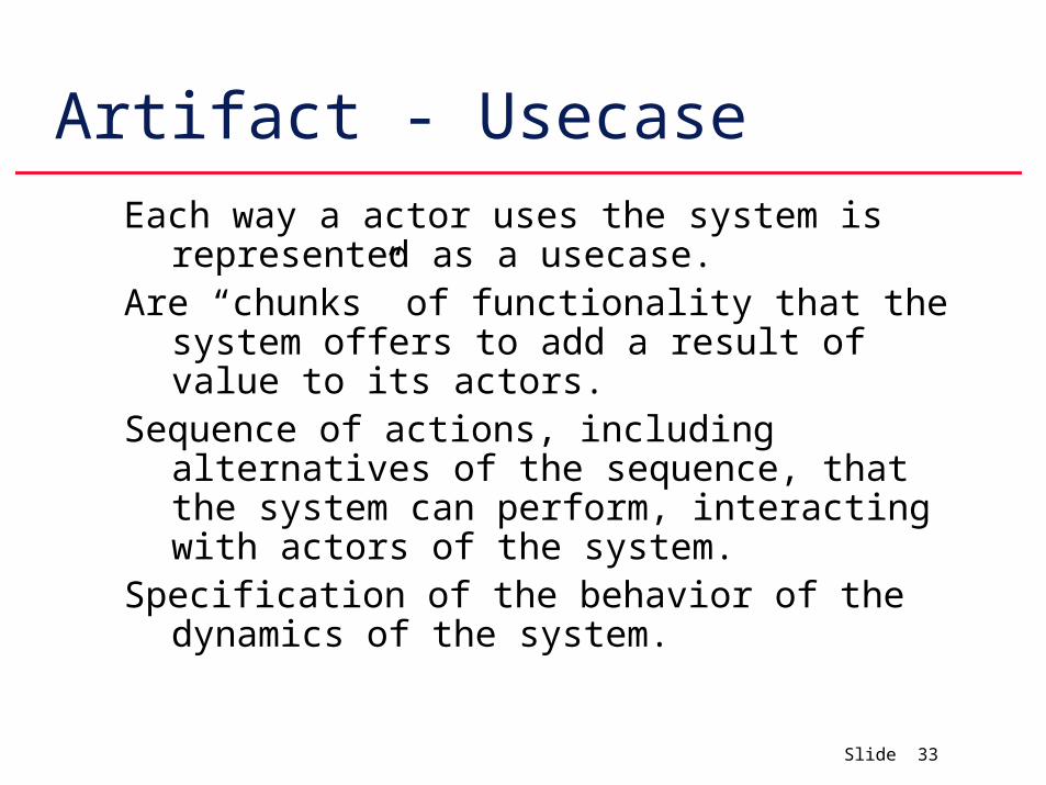
Each way a actor uses the system is represented as a usecase.
Are “chunks” of functionality that the system offers to add a result of value to its actors.
Sequence of actions, including alternatives of the sequence, that the system can perform, interacting with actors of the system.
Specification of the behavior of the dynamics of the system.
Slide 34
Artifact - Usecase
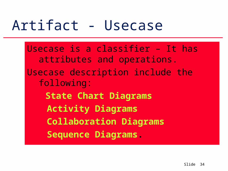
Usecase is a classifier – It has attributes and operations.
Usecase description include the following:
State Chart Diagrams
Activity Diagrams
Collaboration Diagrams
Sequence Diagrams.
Slide 35
Usecase Instance
Execution of usecase.
Interacts with the actor instance and performs a sequence of actions as specified by the usecase.
This sequence is specified by a state chart or activity diagram..
Many paths are possible through a usecase and many are very similar. These are the alternatives through the Usecase.
Slide 36
Path in a usecase
Path through a use case looks as follows:
The Use-Case is instantiated and put in a start state.
Invoked by external message from actor.
It transitions to another state by performing a sequence of actions. Such a sequence contains internal computations, selection of path and message output.
It awaits, in its new state, another message from an actor.
It is invoked again by a new message and so on.
It goes over many states until the usecase is terminated.
Slide 37
Usecase instance - Characteristics
Have attributes that is manipulated during usecase execution.
Usecase instance is atomic.
A Usecase instance does not interact with other instances.
The only interaction that happens in a Usecase is between Actor instances & Usecase instances.
The interference issues between different uses of a system is resolved in the Analysis and design phase when we realize these usecases as collaboration classes and subsystems.
Slide 38
Usecases - Flow of EventsDescribes what the system does when a specified usecase is
performed.
Also specifies how the system interacts with actors when the usecase is performed.
Flow of events for each usecase can be captured as a separate textual description of the use-case's sequence of action.
Description includes a set of sequence of actions that are suitable to modify, review, design, implement and test together and to describe as a section or subsection in the user manual.
Slide 39
Usecase – Special Reqmnts.
Textual description that collects all requirements on a usecase.
Primarily non-functional requirements that are related to the usecase and that are needed to be handled in subsequent workflows such as analysis, design or implementation.
Slide 40
Usecase – How to identify?
The following question may be used to help identify the usecases of the system.
What are the task of each actor?Will any actor create, store, change, remove or read values from the
system?What usecases will create, store, change, remove or read values
from the system.Will any actor need to be informed of certain occurrences in the
system?Will any actor need to inform the system of any external
occurrences? What usecases will support and maintain the system?Can all functional requirements be performed by the usecases?
Slide 41
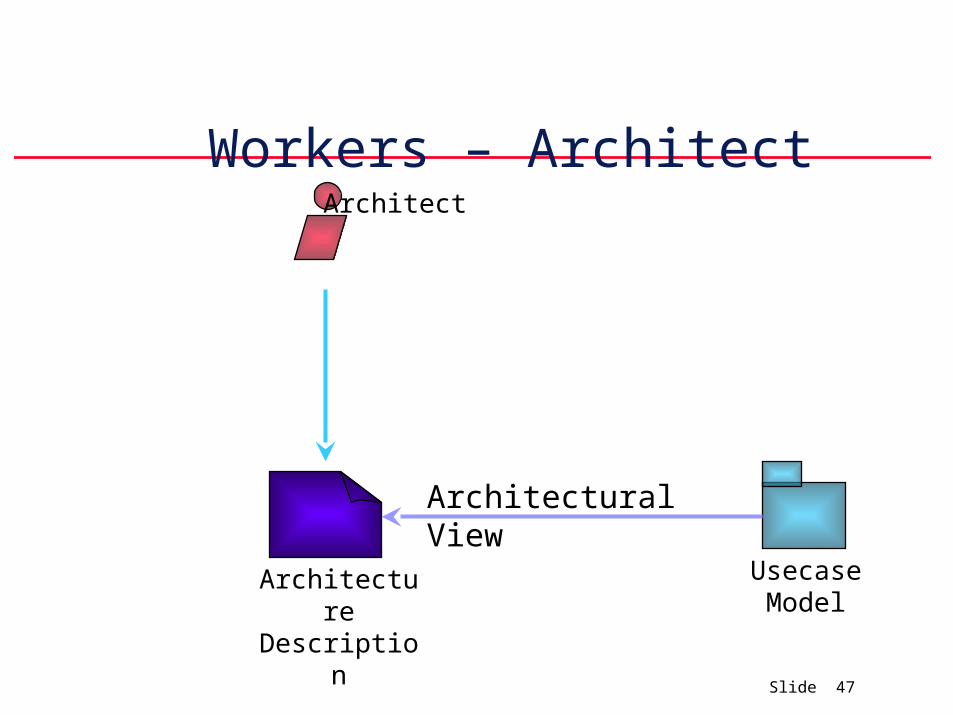
Artifact - Architectural Description
Architectural View of the usecase model depicting the architecturally significant usecases.
Should contain all usecases that describe some important and critical functionality or that involves certain requirements that must be developed early in the software cycle.
This view is used as an input when the usecases are prioritized to be developed within an iteration.
Slide 42
Artifact - Glossary
Used to define important and common terms. Used by the analysts when they describe the system.
Is useful in reaching a consensus among developers regarding the definition of various concepts and notations to reduce the risk of misunderstandings in general.
Can often be derived from a business model or domain model, but because it is less formal it is easier to maintain and more intuitive to discuss with users and customers.
Tends to be more focused on the system to be built instead of system’s context.
Slide 43
Artifact – User Interface PrototypeHelps during requirements capture to understand and
specify the interaction between human actors and system.
Helps us in developing a better user interface and to understand usecases better.
Slide 44
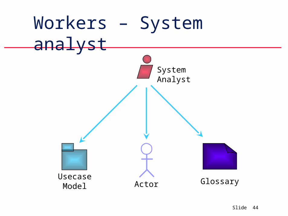
Workers – System analyst
Usecase Model Actor Glossary
System Analyst
Slide 45
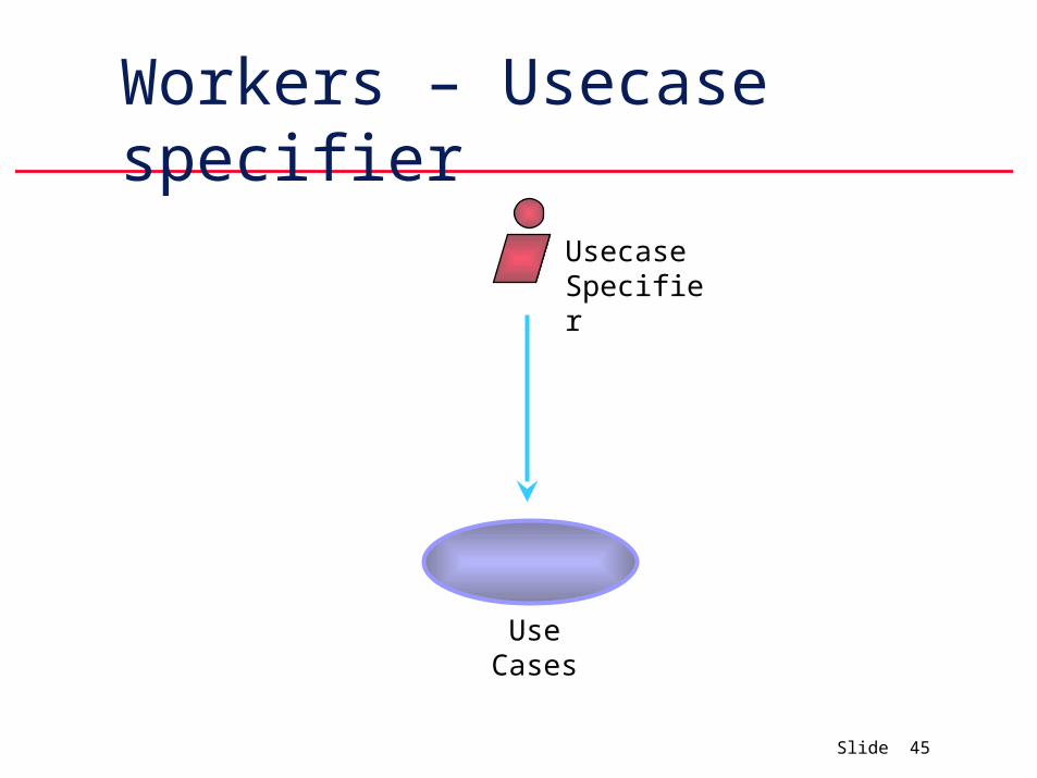
Workers – Usecase specifier
Use Cases
Usecase Specifier
Slide 46
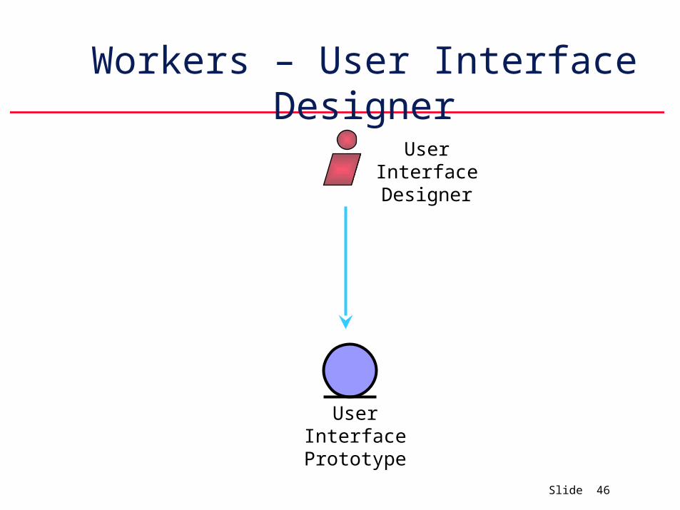
Workers – User Interface Designer
User Interface Prototype
User Interface Designer
Slide 47
Workers – Architect
Architecture Description
Architect
Usecase Model
Architectural View
Slide 48
WORKFLOW
A Sequence of activities which are ordered so that one activity produced output that is used as an input for the next activity.
When workers perform activities they create and modify artifacts.
An activity may be revisited several times and each visit may entail carrying out only a fraction of the activity.
Slide 49
Workflow – Sequence
Perform Find Actors and usecases.
Find architecturally significant usecases to provide input to the prioritization of usecases to be developed in the current iteration.
Detail the usecases.
Suggest suitable user interface for each actor based on the usecases.
Slide 50
Find Actors & Usecases - Why
Delimit our system from its environment.
Outline who and what will interact with the system and what functionality is expected from the system.
Capture and define a glossary of common terms that are essential for creating a detailed description of the system’s functionality.
Slide 51
Find Actors & Usecases - ActivityFinding the actors
Finding the usecases
Briefly describing the usecase
Describing the usecase model as a whole.
The above steps are performed concurrently.
Slide 52
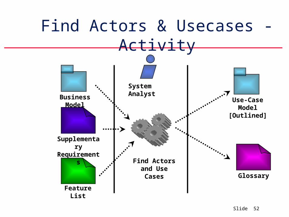
Find Actors & Usecases - Activity
Business Model
System Analyst
Supplementary Requirements
Feature List
Use-Case Model
[Outlined]
Glossary
Find Actors and Use Cases
Slide 53
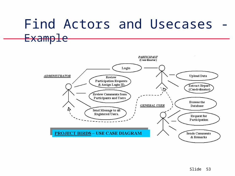
Find Actors and Usecases - Example
Slide 54
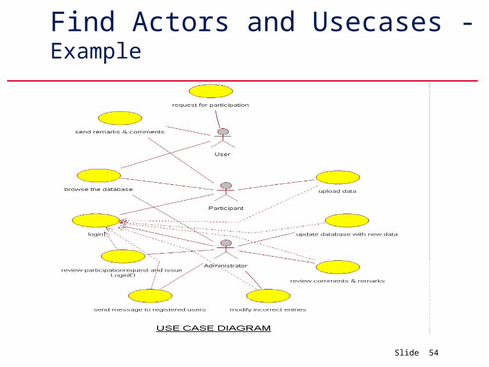
Find Actors and Usecases - Example
Slide 55
Briefly describing each usecase
Identify the usecases and explain them in a few words.
Later describe each usecase briefly in a few sentences.
Later a step by step description of what the system needs to do when interacting with its actors.
Refer to Page 150 of the book for an Example.
Slide 56
Describing the usecase model as a whole
Prepare diagrams and descriptions to explain the use case model as a whole, particularly how the usecase relate to each other and the actors.
To ensure consistency while describing several usecases concurrently, it is practical to develop some glossary of terms.
Terms are derived from classes in domain or business model.
Refer to Page 151 of the book for an Example.
Slide 57
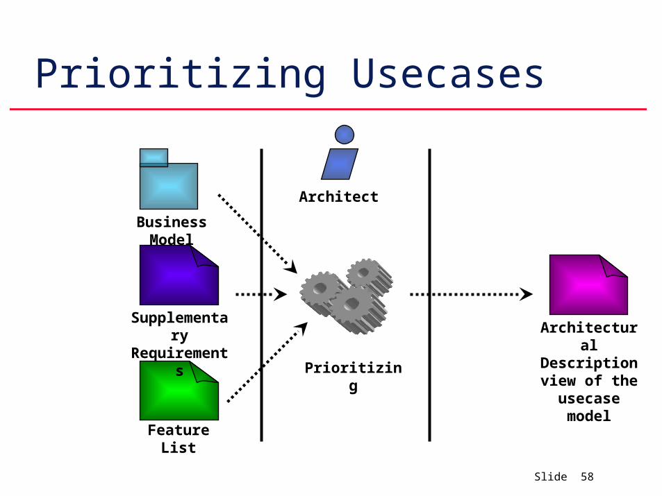
Prioritizing Usecases
Determine which one needs to be developed in earlier iterations and which can be developed in later iterations.
The results are captured in architectural view of the usecase model.
Slide 58
Prioritizing Usecases
Business Model
Architect
Supplementary Requirements
Feature List
Architectural Description view of the
usecase modelPrioritizing
Slide 59
Detailing a Usecase
Describe flow of events in details including how the usecase starts, ends and interacts with actors.
With usecase model and associated usecase diagrams as starting point, the individual usecase specifiers can now describe each usecase in details.
Detail the step-by-step description of each usecase into a precise specification of the sequence of actions.
Slide 60
Detailing a Usecase
How to structure the description to specify all the alternative paths to the usecase.
What to include in a usecase description.
How to formalize the use-case description when necessary.
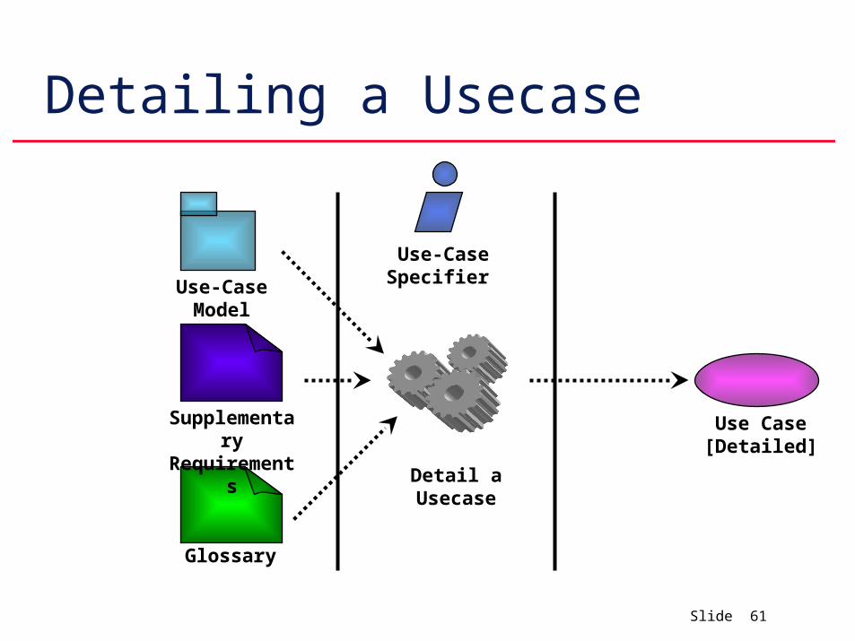
Slide 61
Detailing a Usecase
Use-Case Specifier
Supplementary Requirements
Use Case [Detailed]
Detail a Usecase
Use-Case Model
Glossary
Slide 62
Structuring a Usecase Desc.
Defines the state that use-case instances may enter and possible transition between those states.
Each such transition is a sequence of actions that are performed by a usecase instance when triggered by an event such as a Message.
Artifact – State Transition Diagram.
Slide 63
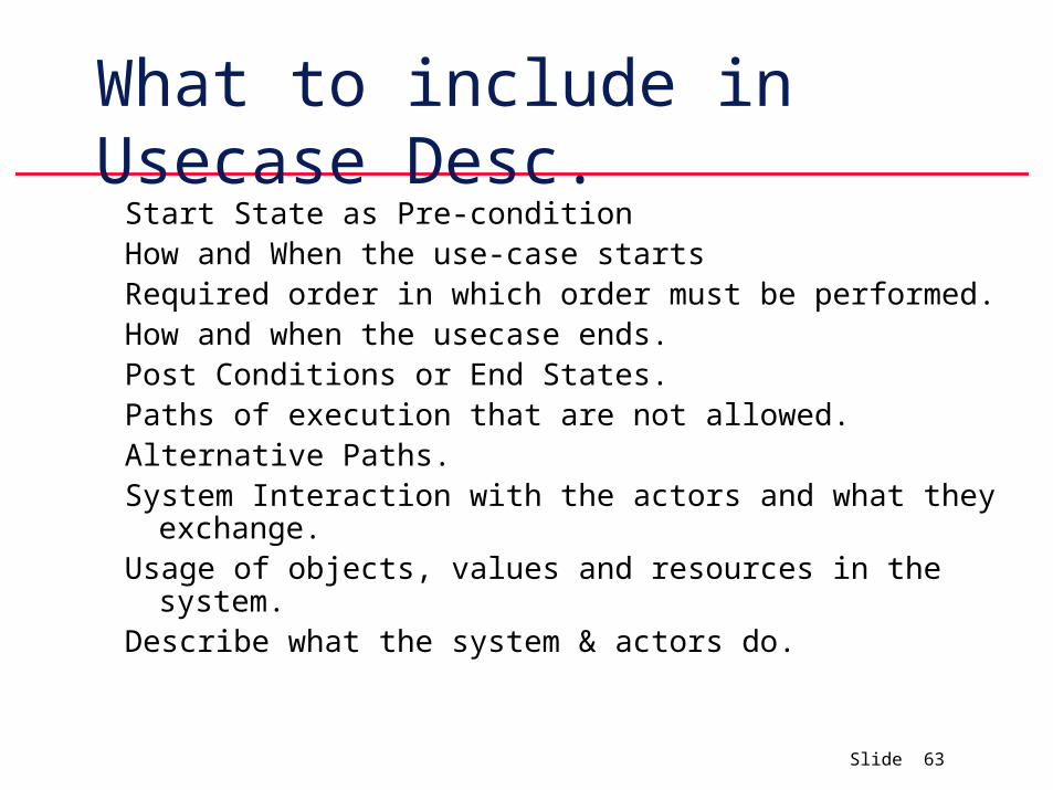
What to include in Usecase Desc.Start State as Pre-conditionHow and When the use-case startsRequired order in which order must be performed.How and when the usecase ends.Post Conditions or End States.Paths of execution that are not allowed.Alternative Paths.System Interaction with the actors and what they exchange.Usage of objects, values and resources in the system.Describe what the system & actors do.
Slide 64
Formalizing the Usecase Desc
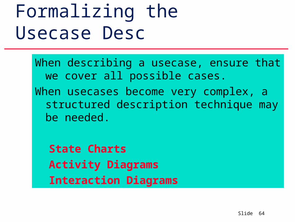
When describing a usecase, ensure that we cover all possible cases.
When usecases become very complex, a structured description technique may be needed.
State Charts
Activity Diagrams
Interaction Diagrams
Slide 65
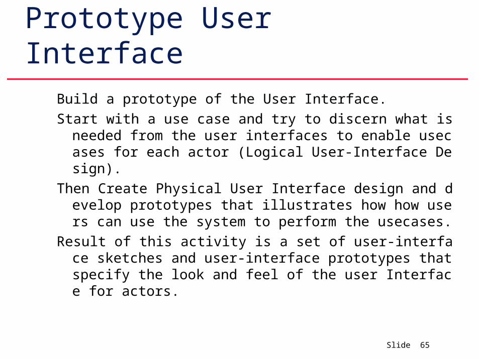
Prototype User Interface
Build a prototype of the User Interface.
Start with a use case and try to discern what is needed from the user interfaces to enable usecases for each actor (Logical User-Interface Design).
Then Create Physical User Interface design and develop prototypes that illustrates how how users can use the system to perform the usecases.
Result of this activity is a set of user-interface sketches and user-interface prototypes that specify the look and feel of the user Interface for actors.
Slide 66
Structuring Use Case Model
To Extract general and shared descriptions of functionality that can be used by more specific use-case descriptions.
Extract additional and optional description of functionality that can extend more specific use-case description.