Embed Size (px)
Citation preview
Slide 1
School ofEngineering
Klenke 163/MAPLD 2004
An FPSLIC-based UAV Control Platform
Robert H. Klenke, Abhishek Handa, Jeffrey E. Quinones, Hung H. (Kevin) Van, Brittiany Wynne
Department of Electrical and Computer EngineeringVirginia Commonwealth University
Richmond, Virginia
Slide 2
School ofEngineering
Klenke 163/MAPLD 2004
Outline
•UAV Goals and System Functions
•Atmel FPSLIC Device Architecture and Features
•UAV Flight Control System Architecture
•UAV Implementation and Testing
•Conclusions and Future Work
Slide 3
School ofEngineering
Klenke 163/MAPLD 2004
UAV System
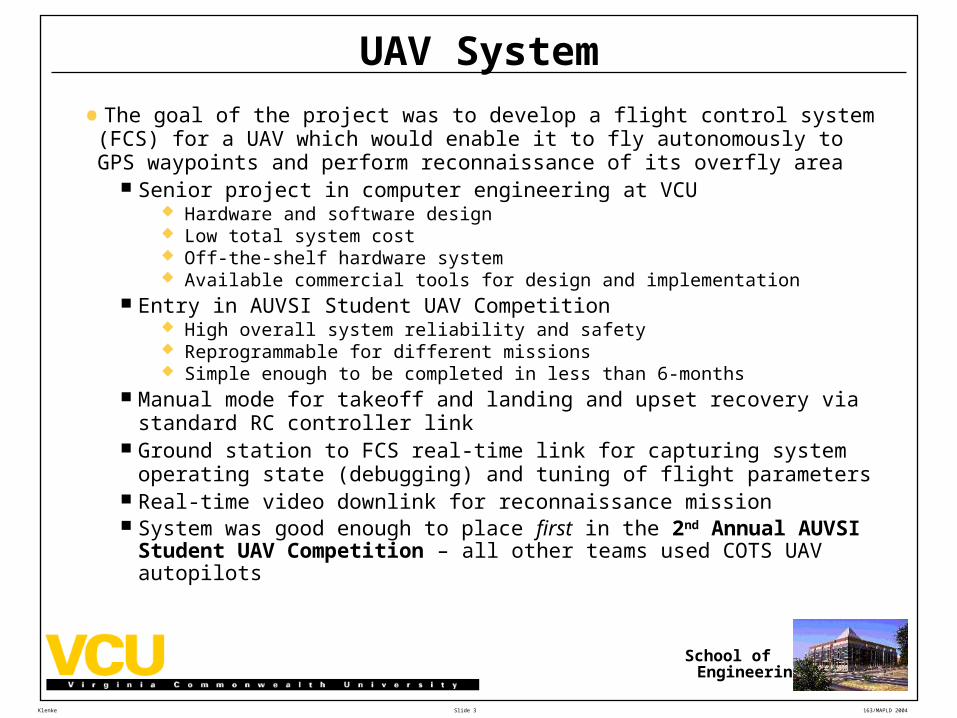
•The goal of the project was to develop a flight control system (FCS) for a UAV which would enable it to fly autonomously to GPS waypoints and perform reconnaissance of its overfly area
Senior project in computer engineering at VCU Hardware and software design Low total system cost Off-the-shelf hardware system Available commercial tools for design and implementation
Entry in AUVSI Student UAV Competition High overall system reliability and safety Reprogrammable for different missions Simple enough to be completed in less than 6-months
Manual mode for takeoff and landing and upset recovery via standard RC controller link
Ground station to FCS real-time link for capturing system operating state (debugging) and tuning of flight parameters
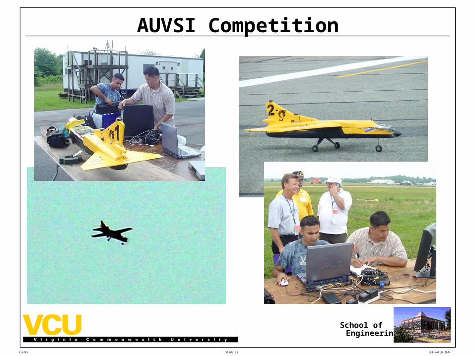
Real-time video downlink for reconnaissance mission System was good enough to place first in the 2nd Annual AUVSI Student UAV
Competition – all other teams used COTS UAV autopilots
Slide 4
School ofEngineering
Klenke 163/MAPLD 2004
ATMEL FPSLIC Device Characteristics
•8-bit AVR microcontroller, EPROM (program memory), SRAM (data memory), 40K gate FPGA on a single device
•Some of the I/O ports on the AVR are connected to package pins, and others are connected to the I/O’s of the FPGA
•External interrupts to the AVR can come from the outside world via a dedicated package pin, or from the FPGA via a built-in interrupt controller connected to FPGA I/O’s
•Some of the FPGA I/O’s are connected to package pins to interface to the outside world
•The AVR contains a dedicated register connected to I/O selection logic that can be used to select and communicate with several different user designed peripherals implemented in the FPGA.
•Atmel has designed an integrated hardware/software codesign and coverification environment to develop FPSLIC applications
•Atmel has available a low-cost FPSLIC-based development board that integrates the device with a number of useful parts such as a power regulator, RS-232 connectors, I/O headers, at 15-segment display, etc.
Slide 5
School ofEngineering
Klenke 163/MAPLD 2004
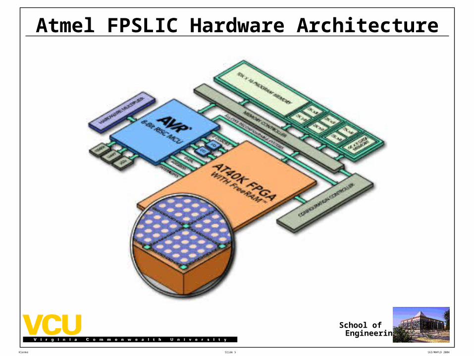
Atmel FPSLIC Hardware Architecture
Slide 6
School ofEngineering
Klenke 163/MAPLD 2004
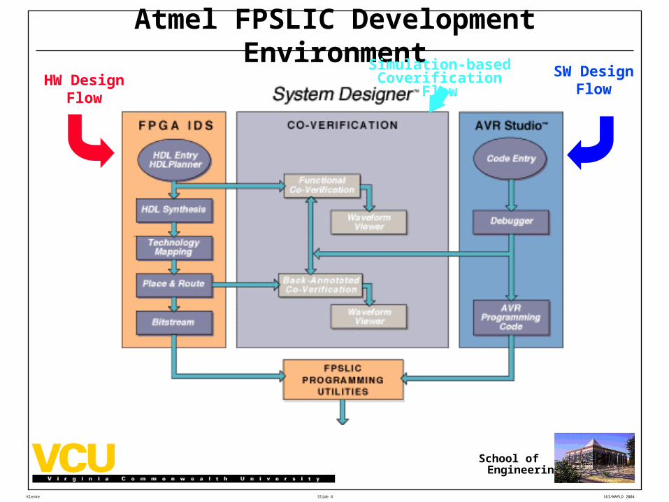
Atmel FPSLIC Development Environment
HW Design Flow
SW Design Flow
Simulation-based Coverification Flow
Slide 7
School ofEngineering
Klenke 163/MAPLD 2004
Reasons for Selection of ATMEL Device
•Low-cost COTS system that is readily available
•Fairly powerful integrated hardware/software system 40K gate FPGA is easily large enough to implement the hardware
required for this application Program and data memory are built-in and, although not large, have
proven adequate for this application Typical microcontroller resources and peripherals are provided
RS-232 ports, interrupt pins, timers and counters, etc.
•Small size, weight, and power consumption due to single integrated device
•Proven, easy-to-use, integrated development environment for both hardware AND software available
Slide 8
School ofEngineering
Klenke 163/MAPLD 2004
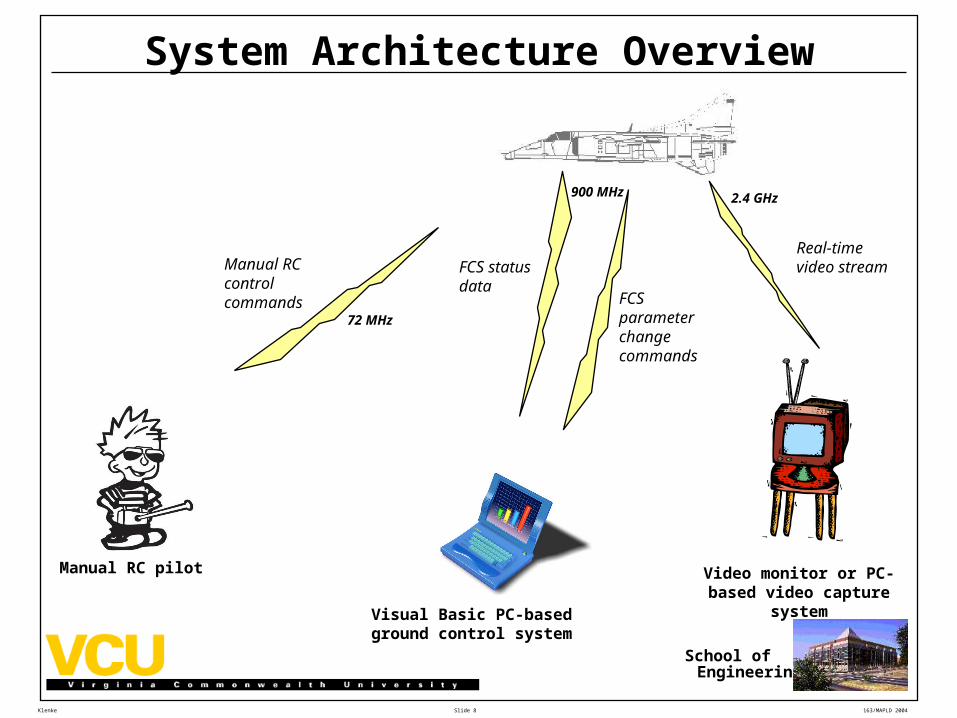
System Architecture Overview
Video monitor or PC-based video capture system
Real-time video streamFCS status
dataFCS parameter change commands
Manual RC control commands
72 MHz
900 MHz 2.4 GHz
Visual Basic PC-based ground control system
Manual RC pilot
Slide 9
School ofEngineering
Klenke 163/MAPLD 2004
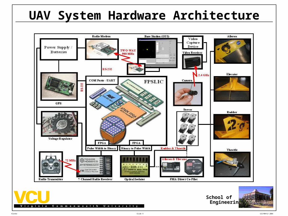
UAV System Hardware Architecture
Slide 10
School ofEngineering
Klenke 163/MAPLD 2004
UAV Functions
•Manual RC pilot is responsible for performing takeoffs and landings and switching FCS from manual to autonomous mode
•Commercial off-the-shelf, Infrared-based horizon sensor is used in autonomous mode to perform pitch and roll stabilization
This gives the FCS a stable platform that it can “steer” around the sky using GPS positioning
•FCS must perform the following functions: Decode the servo positioning pulses being received from the RC pilot
via the RC receiver Detect manual vs. autonomous mode via the position of one of the
channels In manual mode, transfer (generate) the positioning pulses to the servos
exactly as received from the RC pilot Receive position (LLA), and velocity (ENU) information from the GPS
RS-232 serial data via TSIP (Trimble Standard Interface Protocol) at 1-second intervals
Slide 11
School ofEngineering
Klenke 163/MAPLD 2004
UAV Functions (cont.)
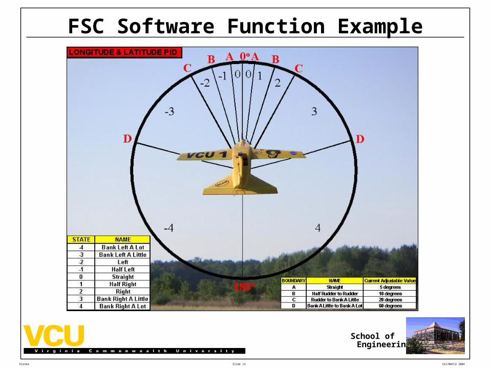
•Determine aircraft position and velocity vs. desired track to next waypoint
•Determine correct aircraft steering commands to retain/regain desired track
•Generate required pulses for servos based on aircraft mode and commanded surface positions
•Detect waypoint arrival and update next waypoint based on mission data
•Provide system state to ground station via radio modem link
•Receive, decode, and implement parameter update commands from ground station
•Detect loss-of-signal from RC transmitter and take appropriate action depending on system state (failsafe)
In manual mode, spiral aircraft to the ground in a low energy state In autonomous mode, fly to first (home) waypoint and wait for signal
from RC transmitter
Slide 12
School ofEngineering
Klenke 163/MAPLD 2004
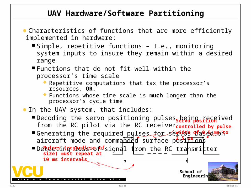
UAV Hardware/Software Partitioning
•Characteristics of functions that are more efficiently implemented in hardware:
Simple, repetitive functions – I.e., monitoring system inputs to insure they remain within a desired range
Functions that do not fit well within the processor’s time scale Repetitive computations that tax the processor’s resources, OR, Functions whose time scale is much longer than the processor’s cycle
time
•In the UAV system, that includes: Decoding the servo positioning pulses being received from the RC pilot
via the RC receiver Generating the required pulses for servos based on aircraft mode and
commanded surface positions Detecting loss-of-signal from the RC transmitter
Servo position controlled by pulse width of 0.5 ms to 2.5 ms
Pulses (regardless of size) must repeat at 10 ms intervals
Slide 13
School ofEngineering
Klenke 163/MAPLD 2004
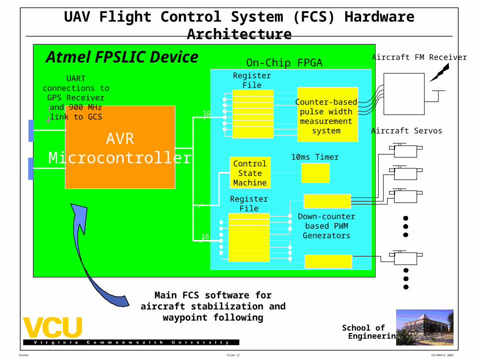
UAV Flight Control System (FCS) Hardware Architecture
AVRMicrocontroller
RegisterFile
Down-counterbased PWMGenerators
ControlState
Machine
10ms Timer
On-Chip FPGA
16
Aircraft Servos
Aircraft FM Receiver
RegisterFile
16
Counter-basedpulse width
measurementsystem
Atmel FPSLIC DeviceUART connections to
GPS Receiver and 900 MHz link to GCS
Main FCS software for aircraft stabilization and
waypoint following
Slide 14
School ofEngineering
Klenke 163/MAPLD 2004
FSC Software Function Example
Slide 15
School ofEngineering
Klenke 163/MAPLD 2004
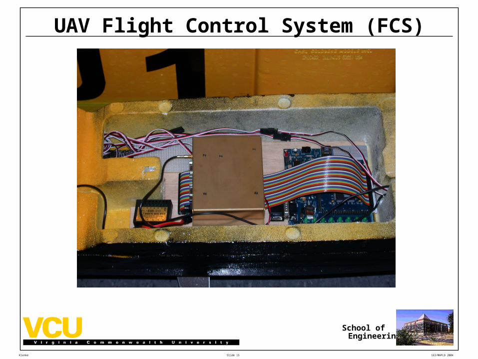
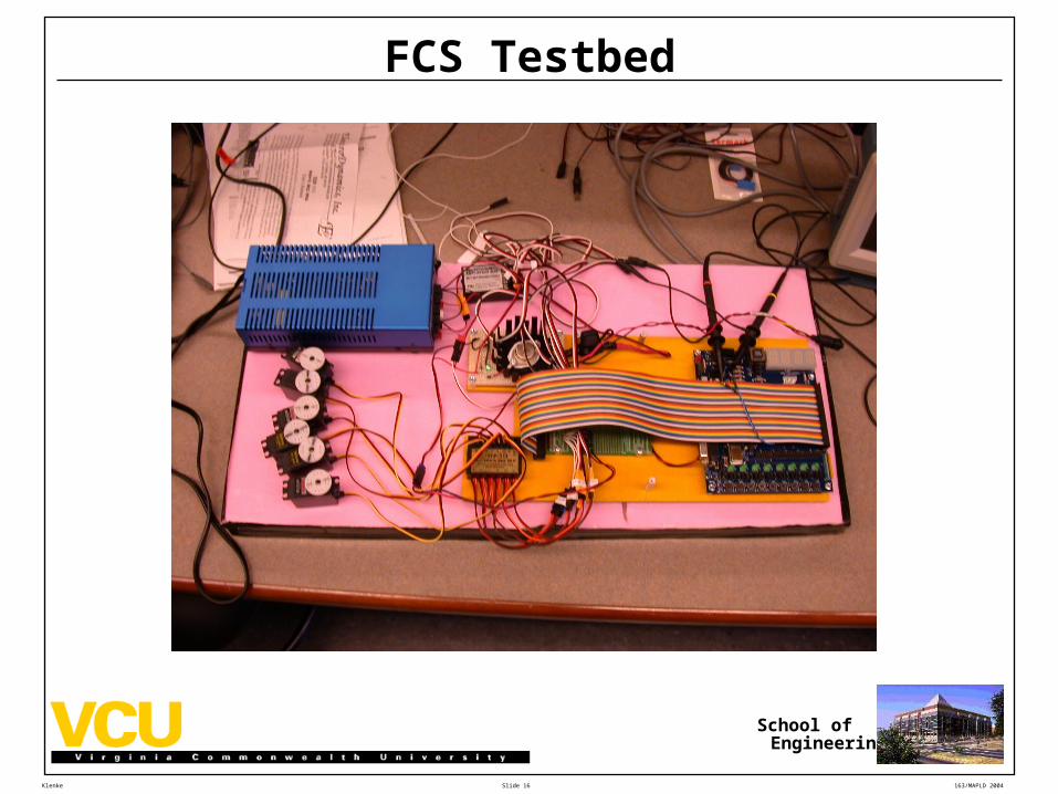
UAV Flight Control System (FCS)
Slide 16
School ofEngineering
Klenke 163/MAPLD 2004
FCS Testbed
Slide 17
School ofEngineering
Klenke 163/MAPLD 2004
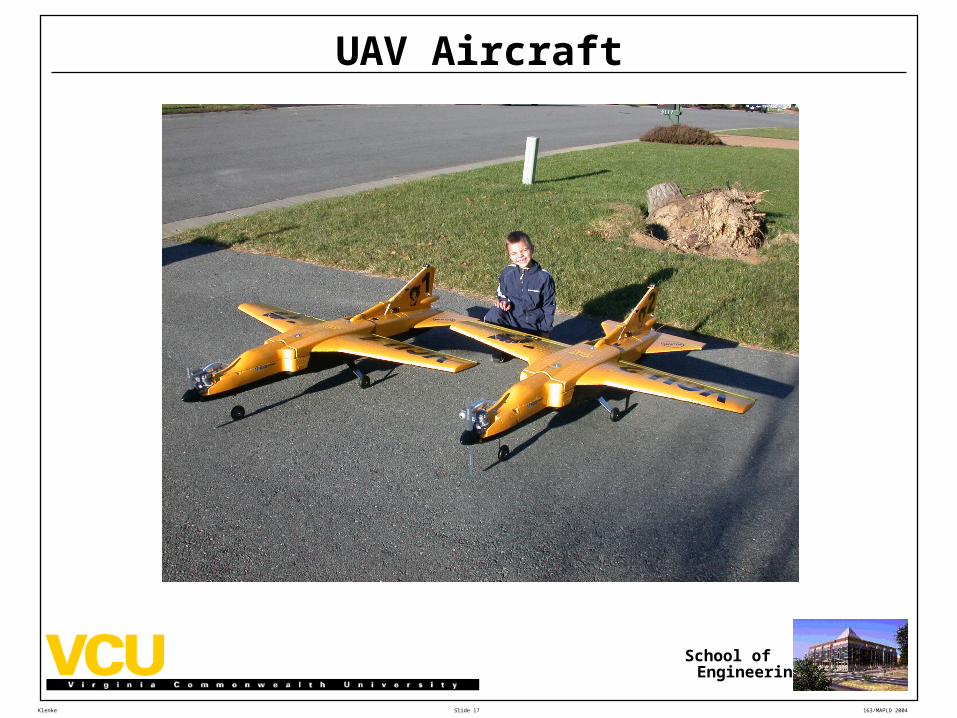
UAV Aircraft
Slide 18
School ofEngineering
Klenke 163/MAPLD 2004
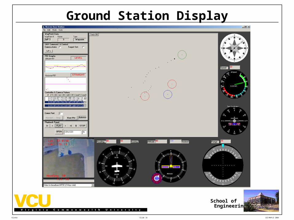
Ground Station Display
Lat: 37.0156 Lon: -76.13
Heading: 50 Alt: 98
Slide 19
School ofEngineering
Klenke 163/MAPLD 2004
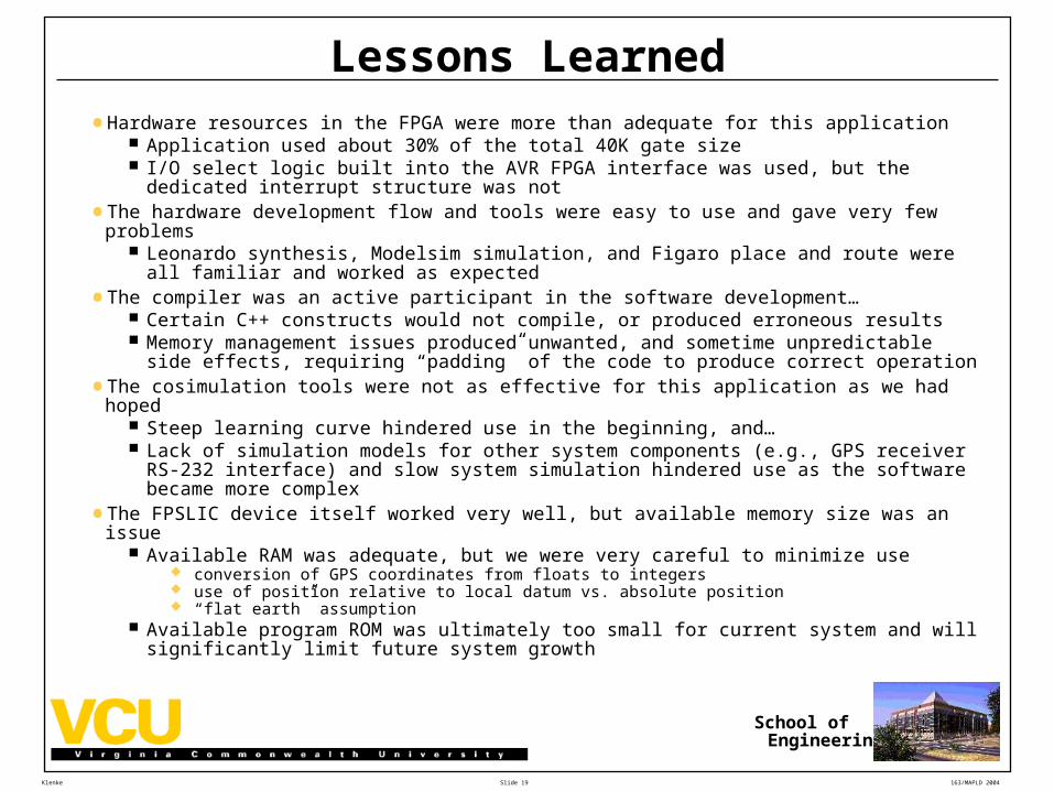
Lessons Learned
• Hardware resources in the FPGA were more than adequate for this application Application used about 30% of the total 40K gate size I/O select logic built into the AVR FPGA interface was used, but the dedicated interrupt
structure was not
• The hardware development flow and tools were easy to use and gave very few problems Leonardo synthesis, Modelsim simulation, and Figaro place and route were all familiar and
worked as expected
• The compiler was an active participant in the software development… Certain C++ constructs would not compile, or produced erroneous results Memory management issues produced unwanted, and sometime unpredictable side
effects, requiring “padding” of the code to produce correct operation
• The cosimulation tools were not as effective for this application as we had hoped Steep learning curve hindered use in the beginning, and… Lack of simulation models for other system components (e.g., GPS receiver RS-232
interface) and slow system simulation hindered use as the software became more complex
• The FPSLIC device itself worked very well, but available memory size was an issue Available RAM was adequate, but we were very careful to minimize use
conversion of GPS coordinates from floats to integers use of position relative to local datum vs. absolute position “flat earth” assumption
Available program ROM was ultimately too small for current system and will significantly limit future system growth
Slide 20
School ofEngineering
Klenke 163/MAPLD 2004
Conclusions and Future Work
•System has been fully developed and tested Flight testing took place at Felker Army Airfield at Ft. Eustis in VA under their
UAV development efforts Some interest in further development of this system has been generated
because of its low cost
•Future improvements to the system architecture are being considered: The use of a gyro unit and additional software to provide wing leveling in lieu of
the commercial infrared-based CoPilot unit Addition of pressure sensors for altitude and airspeed measurement to allow
more precise control More sophisticated, linear PID algorithms for altitude and heading control
•Migration of the FCS to a Xilinx Microblaze-based implementation is also being considered:
Faster, more powerful 32-bit processor More flexibility in changing/adding to system architecture Toolset more difficult to use Problems such as adding off-chip memory for data and storage to a
Microblaze-based system must be addressed
Slide 21
School ofEngineering
Klenke 163/MAPLD 2004
AUVSI Competition


![[Clarinet_Institute] Quinones 15 Duets](https://img.pdfslide.net/doc/110x75/577cda4a1a28ab9e78a548de/clarinetinstitute-quinones-15-duets.jpg)