Embed Size (px)
Citation preview
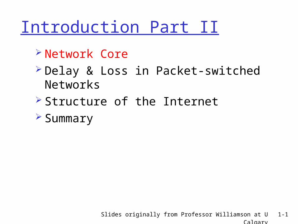
Slides originally from Professor Williamson at U Calgary 1-1
Introduction Part II Network Core Delay & Loss in Packet-switched
Networks Structure of the Internet Summary
Slides originally from Professor Williamson at U Calgary 1-2
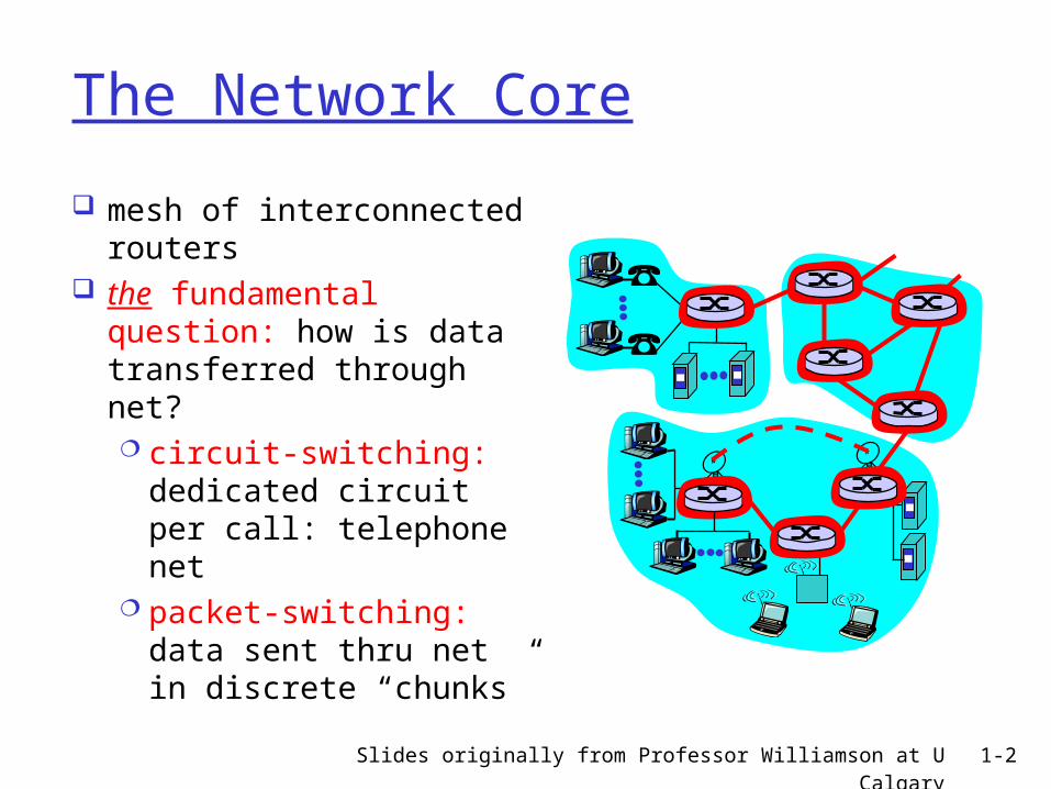
The Network Core
mesh of interconnected routers
the fundamental question: how is data transferred through net? circuit-switching:
dedicated circuit per call: telephone net
packet-switching: data sent thru net in discrete “chunks”
Slides originally from Professor Williamson at U Calgary 1-3
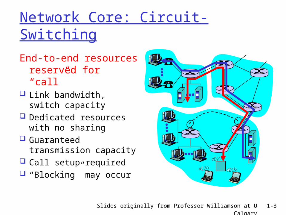
Network Core: Circuit-Switching
End-to-end resources reserved for “call”
Link bandwidth, switch capacity
Dedicated resources with no sharing
Guaranteed transmission capacity
Call setup required “Blocking” may occur
Slides originally from Professor Williamson at U Calgary 1-4
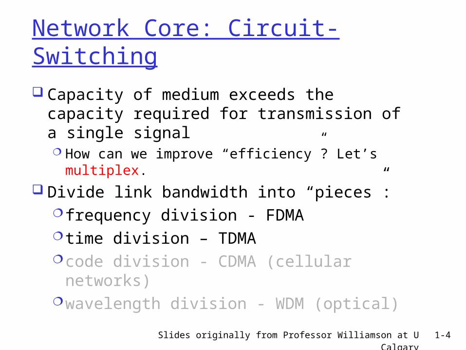
Network Core: Circuit-Switching
Capacity of medium exceeds the capacity required for transmission of a single signal How can we improve “efficiency”? Let’s
multiplex. Divide link bandwidth into “pieces”:
frequency division - FDMAtime division – TDMAcode division - CDMA (cellular networks)wavelength division - WDM (optical)
Slides originally from Professor Williamson at U Calgary 1-5
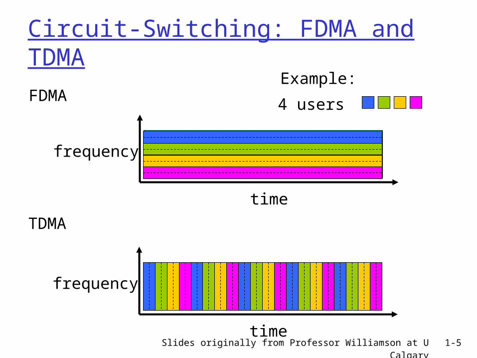
Circuit-Switching: FDMA and TDMA
FDMA
frequency
time
TDMA
frequency
time
4 users
Example:
Slides originally from Professor Williamson at U Calgary 1-6
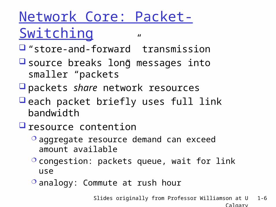
Network Core: Packet-Switching
“store-and-forward” transmission source breaks long messages into
smaller “packets” packets share network resources
each packet briefly uses full link bandwidth
resource contention aggregate resource demand can exceed
amount available congestion: packets queue, wait for link use analogy: Commute at rush hour
Slides originally from Professor Williamson at U Calgary 1-7
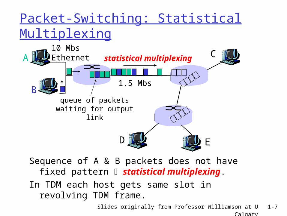
Packet-Switching: Statistical Multiplexing
Sequence of A & B packets does not have fixed pattern statistical multiplexing.
In TDM each host gets same slot in revolving TDM frame.
A
B
C10 MbsEthernet
1.5 Mbs
D E
statistical multiplexing
queue of packetswaiting for output
link
Slides originally from Professor Williamson at U Calgary 1-8
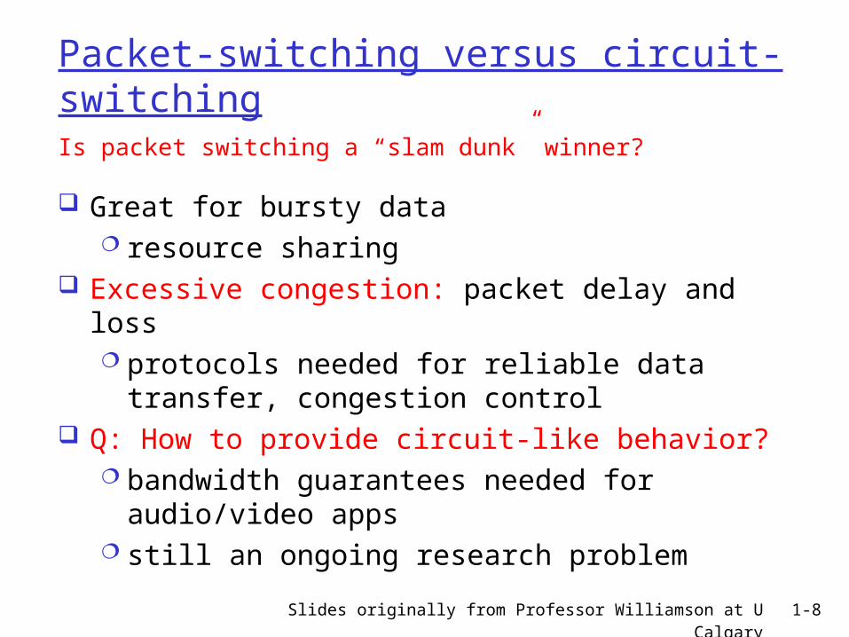
Packet-switching versus circuit-switching
Great for bursty data resource sharing
Excessive congestion: packet delay and loss protocols needed for reliable data transfer,
congestion control Q: How to provide circuit-like behavior?
bandwidth guarantees needed for audio/video apps
still an ongoing research problem
Is packet switching a “slam dunk” winner?
Slides originally from Professor Williamson at U Calgary 1-9
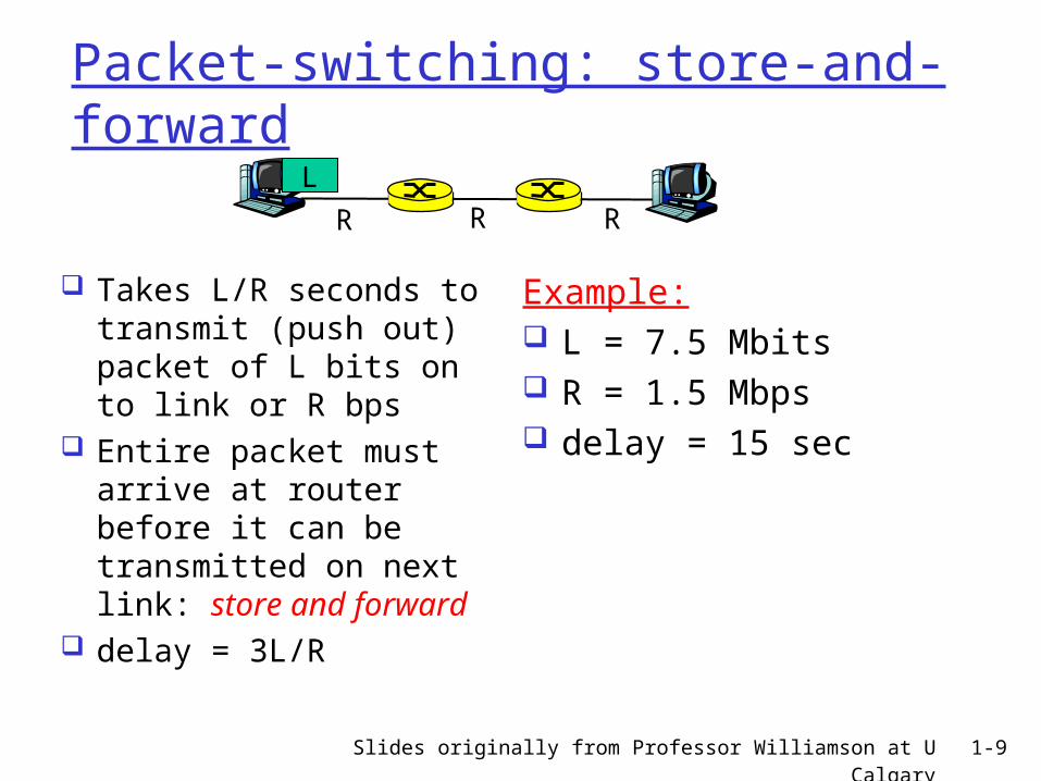
Packet-switching: store-and-forward
Takes L/R seconds to transmit (push out) packet of L bits on to link or R bps
Entire packet must arrive at router before it can be transmitted on next link: store and forward
delay = 3L/R
Example: L = 7.5 Mbits R = 1.5 Mbps delay = 15 sec
R R RL
Slides originally from Professor Williamson at U Calgary 1-10
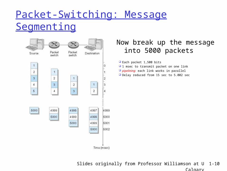
Packet-Switching: Message Segmenting
Now break up the message into 5000 packets
Each packet 1,500 bits 1 msec to transmit packet on one link pipelining: each link works in parallel Delay reduced from 15 sec to 5.002 sec
Slides originally from Professor Williamson at U Calgary 1-11
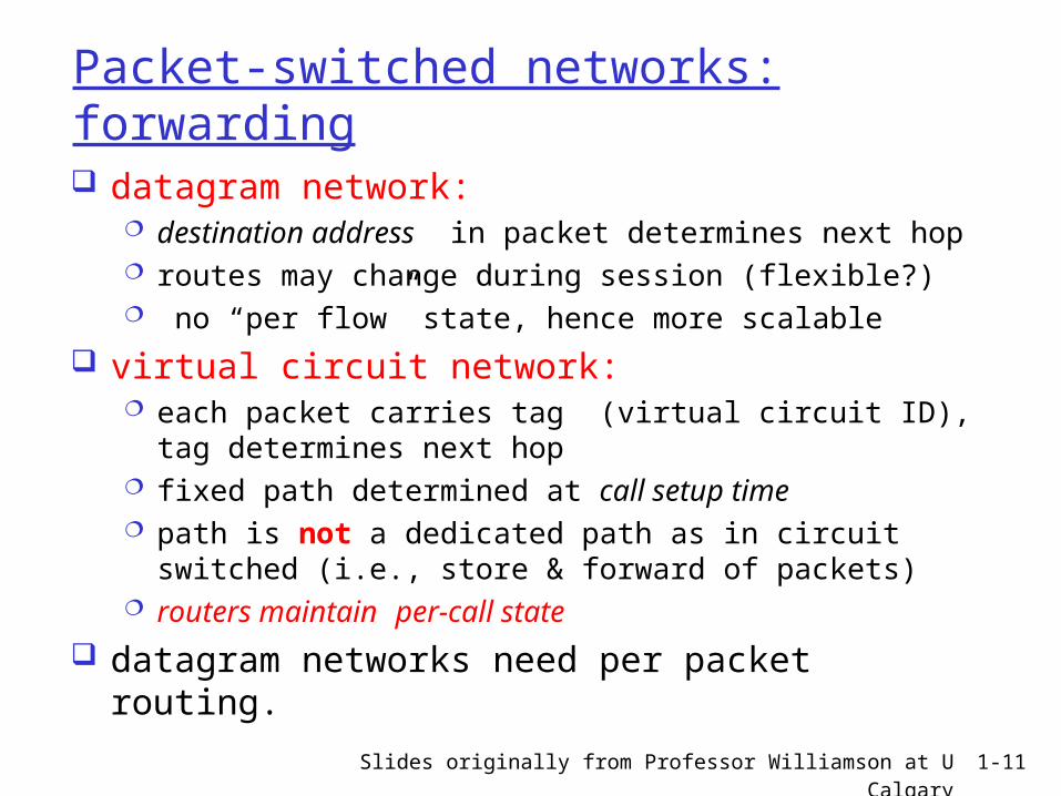
Packet-switched networks: forwarding datagram network:
destination address in packet determines next hop routes may change during session (flexible?) no “per flow” state, hence more scalable
virtual circuit network: each packet carries tag (virtual circuit ID), tag
determines next hop fixed path determined at call setup time path is not a dedicated path as in circuit switched (i.e.,
store & forward of packets) routers maintain per-call state
datagram networks need per packet routing.
Slides originally from Professor Williamson at U Calgary 1-12
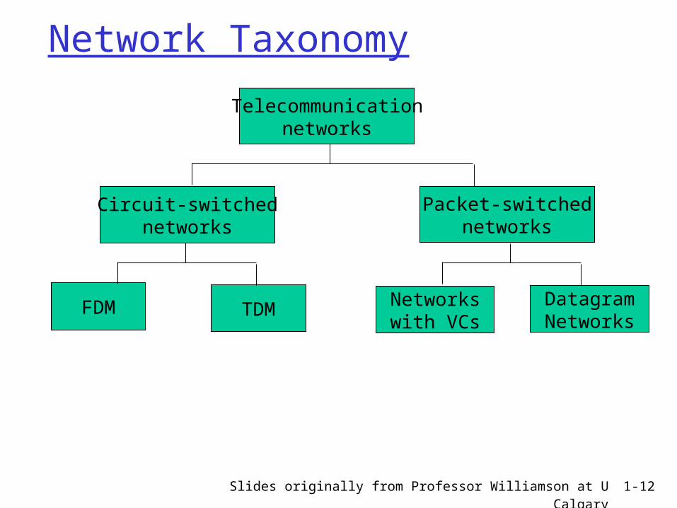
Network Taxonomy
Telecommunicationnetworks
Circuit-switchednetworks
FDM TDM
Packet-switchednetworks
Networkswith VCs
DatagramNetworks
Slides originally from Professor Williamson at U Calgary 1-13
Roadmap Network Core Delay & Loss in Packet-switched
Networks Structure of the Internet Summary
Slides originally from Professor Williamson at U Calgary 1-14
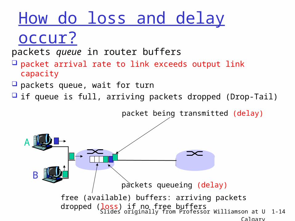
How do loss and delay occur?packets queue in router buffers packet arrival rate to link exceeds output link
capacity packets queue, wait for turn if queue is full, arriving packets dropped (Drop-Tail)
A
B
packet being transmitted (delay)
packets queueing (delay)
free (available) buffers: arriving packets dropped (loss) if no free buffers
Slides originally from Professor Williamson at U Calgary 1-15
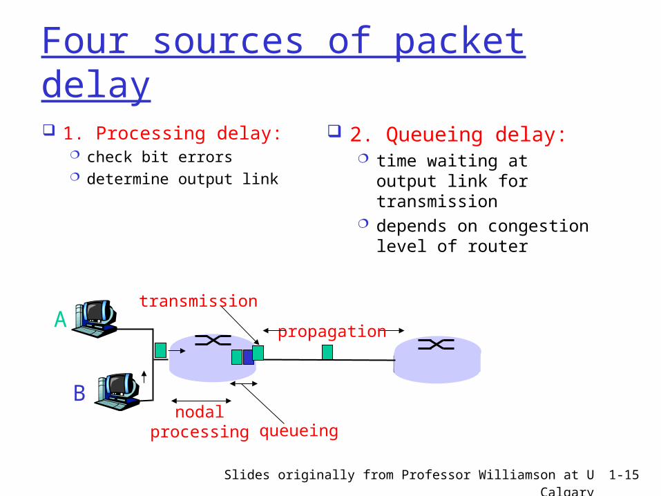
Four sources of packet delay
1. Processing delay: check bit errors determine output link
A
B
propagation
transmission
nodalprocessing queueing
2. Queueing delay: time waiting at output
link for transmission depends on congestion
level of router
Slides originally from Professor Williamson at U Calgary 1-16
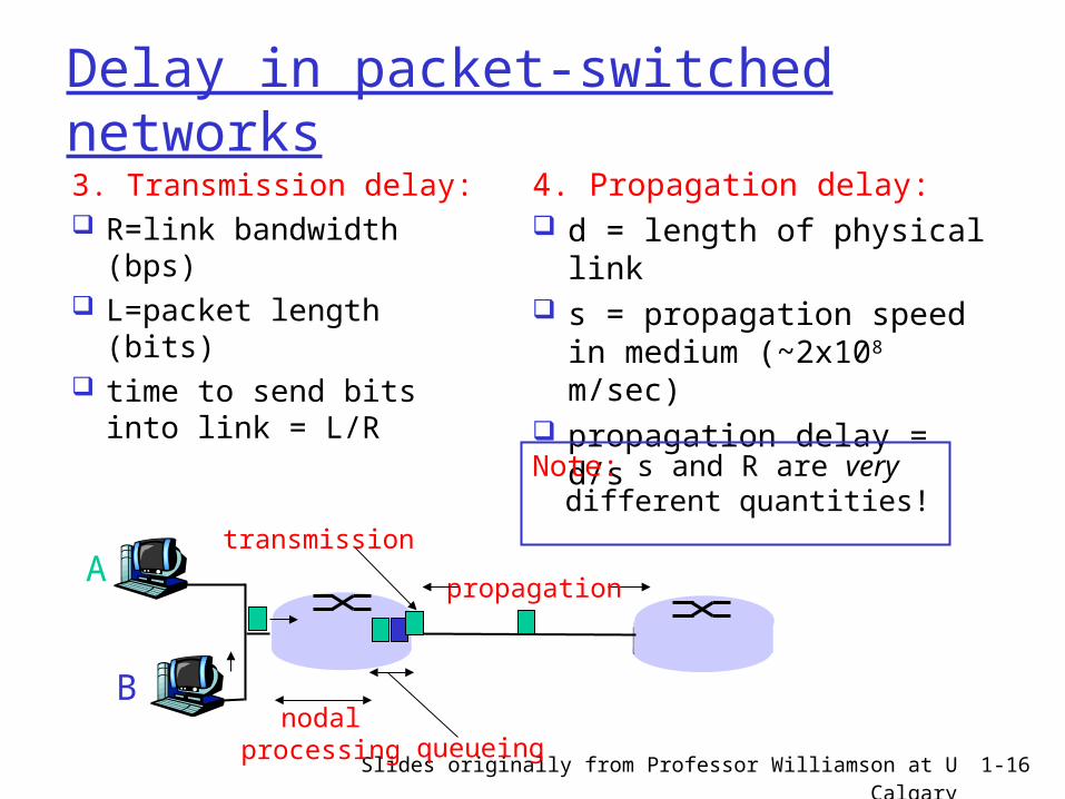
Delay in packet-switched networks3. Transmission delay: R=link bandwidth
(bps) L=packet length (bits) time to send bits into
link = L/R
4. Propagation delay: d = length of physical
link s = propagation speed in
medium (~2x10⁸ m/sec) propagation delay = d/s
A
B
propagation
transmission
nodalprocessing queueing
Note: s and R are very different quantities!
Slides originally from Professor Williamson at U Calgary 1-17
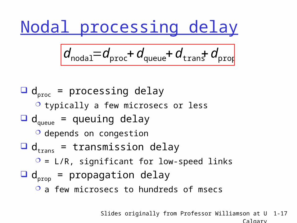
Nodal processing delay
dproc = processing delay typically a few microsecs or less
dqueue = queuing delay depends on congestion
dtrans = transmission delay = L/R, significant for low-speed links
dprop = propagation delay a few microsecs to hundreds of msecs
proptransqueueprocnodal ddddd
Slides originally from Professor Williamson at U Calgary 1-18
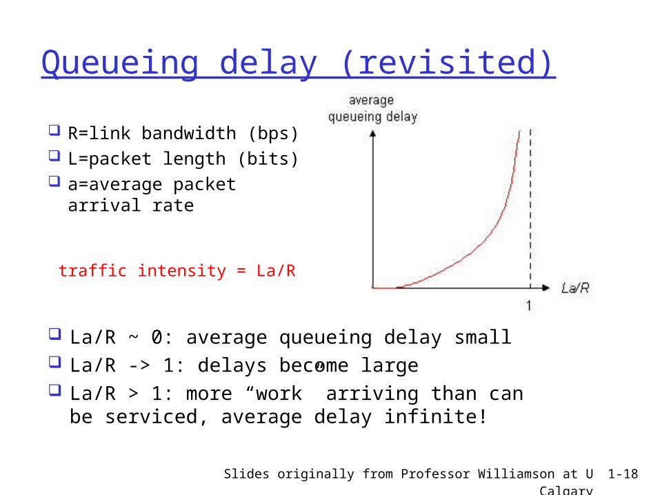
Queueing delay (revisited)
R=link bandwidth (bps) L=packet length (bits) a=average packet
arrival rate
traffic intensity = La/R
La/R ~ 0: average queueing delay small La/R -> 1: delays become large La/R > 1: more “work” arriving than can
be serviced, average delay infinite!
Slides originally from Professor Williamson at U Calgary 1-19
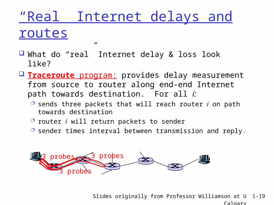
“Real” Internet delays and routes What do “real” Internet delay & loss look like? Traceroute program: provides delay
measurement from source to router along end-end Internet path towards destination. For all i: sends three packets that will reach router i on path
towards destination router i will return packets to sender sender times interval between transmission and reply.
3 probes
3 probes
3 probes
Slides originally from Professor Williamson at U Calgary 1-20
Roadmap Network Core Delay & Loss in Packet-switched
Networks Structure of the Internet Summary
Slides originally from Professor Williamson at U Calgary 1-21
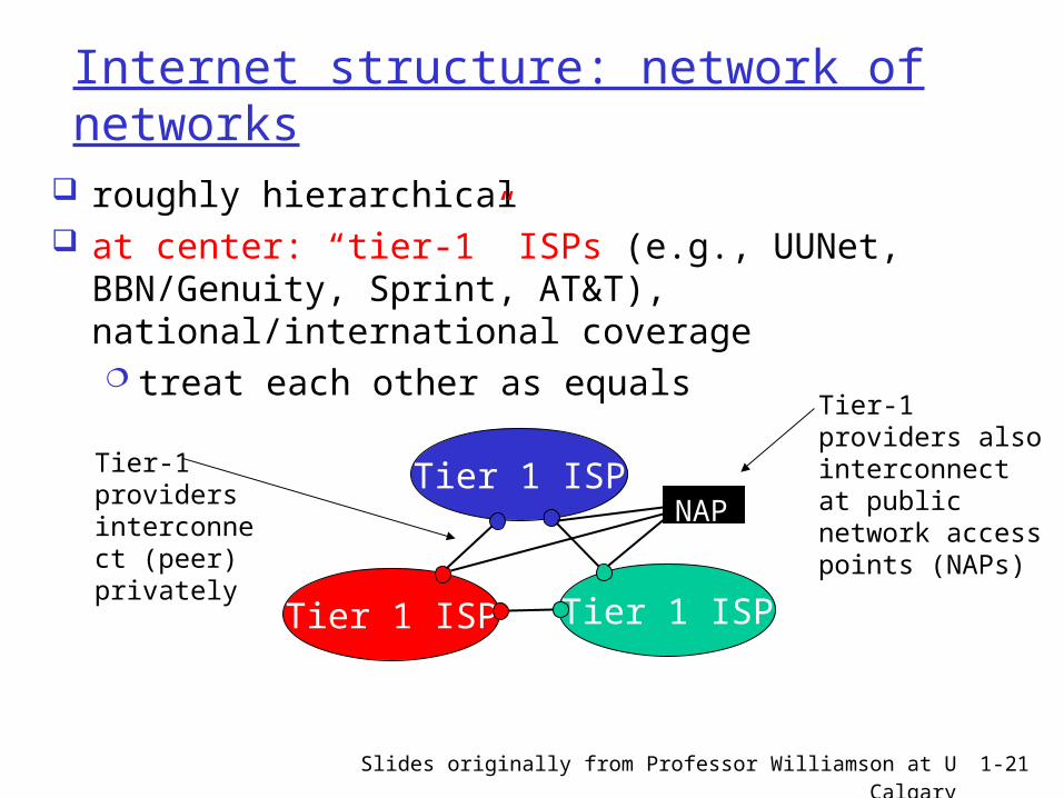
Internet structure: network of networks
roughly hierarchical at center: “tier-1” ISPs (e.g., UUNet, BBN/Genuity,
Sprint, AT&T), national/international coverage treat each other as equals
Tier 1 ISP
Tier 1 ISP
Tier 1 ISP
Tier-1 providers interconnect (peer) privately
NAP
Tier-1 providers also interconnect at public network access points (NAPs)
Slides originally from Professor Williamson at U Calgary 1-22
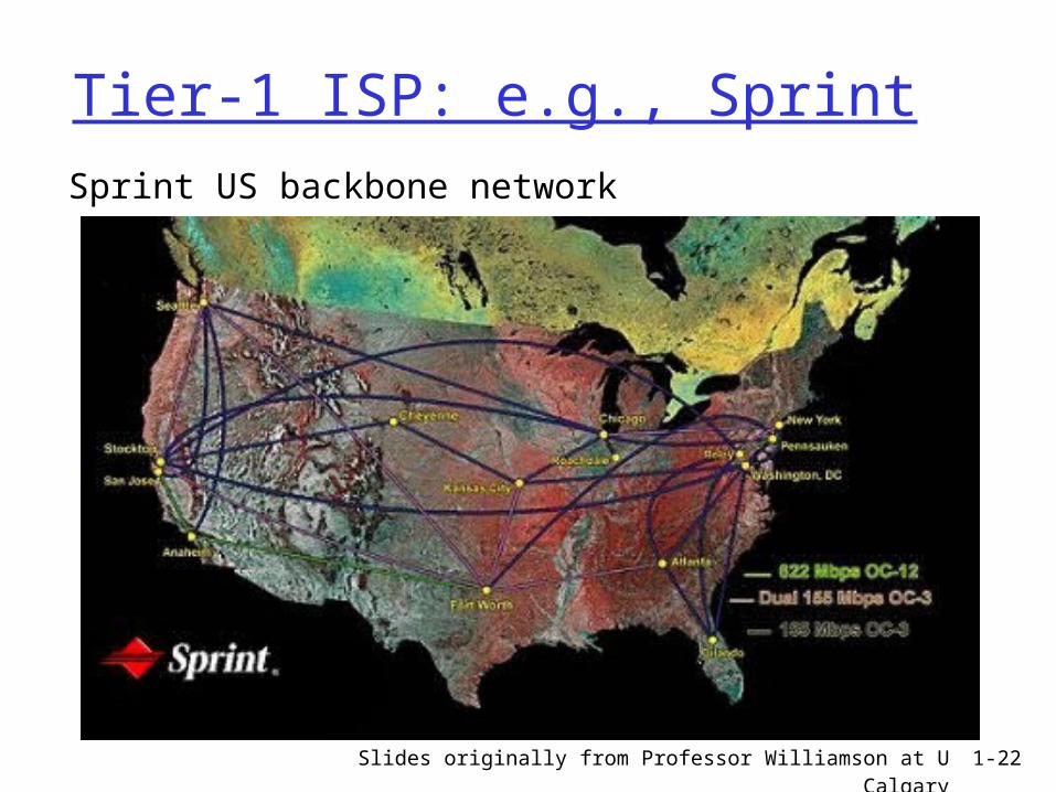
Tier-1 ISP: e.g., SprintSprint US backbone network
Slides originally from Professor Williamson at U Calgary 1-23
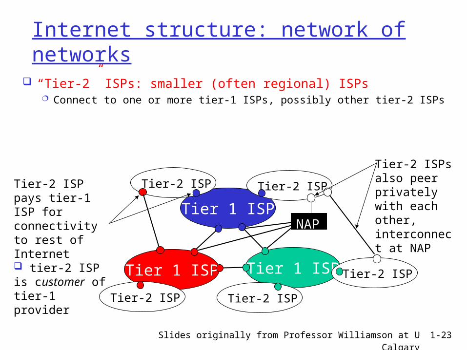
Internet structure: network of networks
“Tier-2” ISPs: smaller (often regional) ISPs Connect to one or more tier-1 ISPs, possibly other tier-2 ISPs
Tier 1 ISP
Tier 1 ISP
Tier 1 ISP
NAP
Tier-2 ISPTier-2 ISP
Tier-2 ISP Tier-2 ISP
Tier-2 ISP
Tier-2 ISP pays tier-1 ISP for connectivity to rest of Internet tier-2 ISP is customer oftier-1 provider
Tier-2 ISPs also peer privately with each other, interconnect at NAP
Slides originally from Professor Williamson at U Calgary 1-24
Internet structure: network of networks
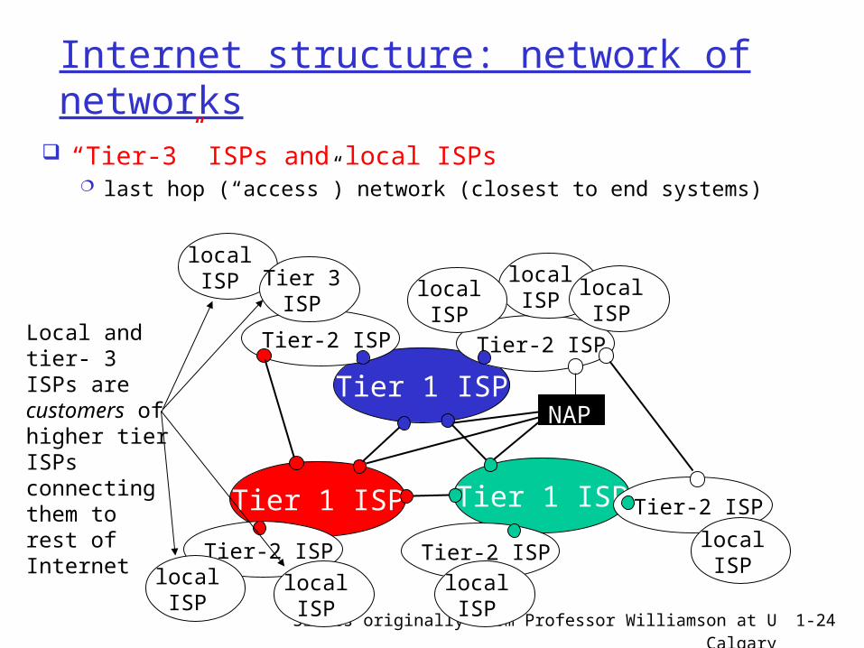
“Tier-3” ISPs and local ISPs last hop (“access”) network (closest to end systems)
Tier 1 ISP
Tier 1 ISP
Tier 1 ISP
NAP
Tier-2 ISPTier-2 ISP
Tier-2 ISP Tier-2 ISP
Tier-2 ISP
localISPlocal
ISPlocalISP
localISP
localISP Tier 3
ISP
localISP
localISP
localISP
Local and tier- 3 ISPs are customers ofhigher tier ISPsconnecting them to rest of Internet
Slides originally from Professor Williamson at U Calgary 1-25
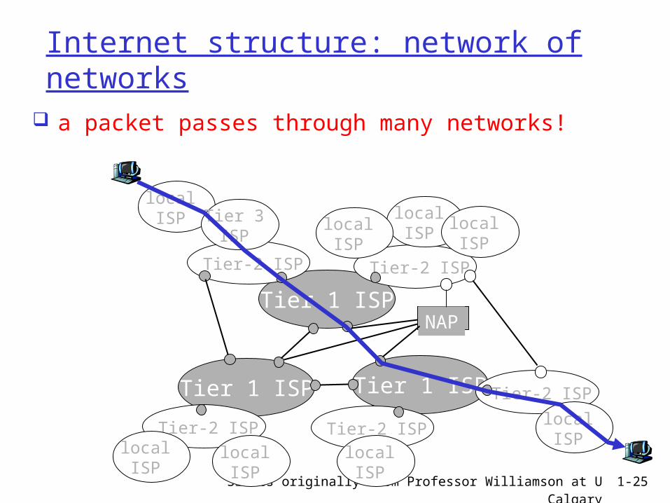
Internet structure: network of networks
a packet passes through many networks!
Tier 1 ISP
Tier 1 ISP
Tier 1 ISP
NAP
Tier-2 ISPTier-2 ISP
Tier-2 ISP Tier-2 ISP
Tier-2 ISP
localISPlocal
ISPlocalISP
localISP
localISP Tier 3
ISP
localISP
localISP
localISP
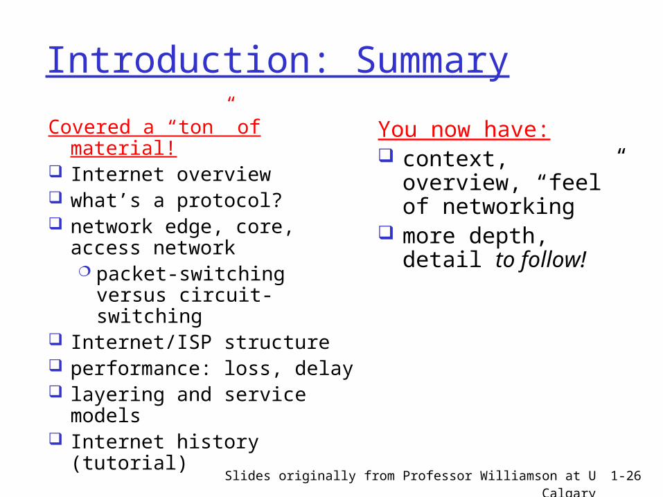
Slides originally from Professor Williamson at U Calgary 1-26
Introduction: Summary
Covered a “ton” of material! Internet overview what’s a protocol? network edge, core,
access network packet-switching
versus circuit-switching Internet/ISP structure performance: loss, delay layering and service
models Internet history (tutorial)
You now have: context, overview,
“feel” of networking more depth, detail
to follow!