Embed Size (px)
Citation preview
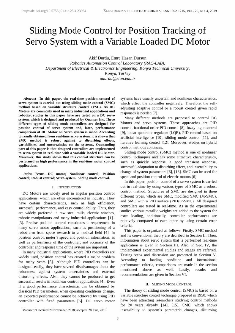
ELEKTRONIKA IR ELEKTROTECHNIKA, ISSN 1392-1215, VOL. 25, NO. 4, 2019
1Abstract—In this paper, the real-time position control of
servo system is carried out using sliding mode control (SMC)
method based on variable structure control (VSC). As DC
Motors are commonly used in many industrial applications and
robotics, studies in this paper have are tested on a DC servo
system, which is designed and produced by Quanser Inc. Three
different types of sliding mode controllers are designed for
position control of servo system and, later, performance
comparison of DC Motor on Servo system is made. According
to results obtained from real-time servo system, it is shown that
SMC method is robust against to disturbing effects,
variabilities, and uncertainties on the systems. Outstanding
part of this paper is that designed controllers are implemented
to servo system in real-time with a variable loaded DC Motor.
Moreover, this study shows that this control structure can be
performed as high performance in the real-time motor control
applications.
Index Terms—DC motor; Nonlinear control; Position
control; Robust control; Servo system; Sliding mode control.
I. INTRODUCTION
DC Motors are widely used in angular position control
applications, which are often encountered in industry. They
have certain characteristics, such as high efficiency,
successful performance, and easy controllability. Thus, they
are widely preferred in raw steel mills, electric winches,
robotic manipulators and many industrial applications [1]–
[3]. Precise position control constitutes a requirement in
many servo motor applications, such as positioning of a
robot arm from space research to a medical field [4]. In
position control, motor’s speed and position information, as
well as performance of the controller, and accuracy of the
controller and response time of the system are important.
In many industrial applications, where PID controllers are
widely used, position control has created a major problem
for many years [5]. Although PID controllers can be
designed easily, they have several disadvantages about the
robustness against system uncertainties and external
disturbing effects. Also, they cannot be produced to get
successful results in nonlinear control applications [4]. Even
if a good performance characteristic can be obtained by
classical PID parameters, when operating conditions change,
an expected performance cannot be achieved by using PID
controller with fixed parameters [6]. DC servo motor
Manuscript received 20 November, 2018; accepted 28 June, 2019.
systems have usually uncertain and nonlinear characteristics,
which effect the controller negatively. Therefore, the self-
adjusting adaptive control or a robust control given rapid
responses is needed [7].
Many different methods are proposed to control DC
Motors and servo systems. These approaches are PID
control, fractional order PID control [8], fuzzy logic control
[9], linear quadratic regulator (LQR), PID control based on
artificial intelligence [10], sliding mode control [11], and
iterative learning control [12]. Moreover, studies on hybrid
control methods continues.
Sliding mode control (SMC) method is one of nonlinear
control techniques and has some attractive characteristics,
such as quickly response, a good transient response,
successful adaptation to disturbing effect, and insensibility to
change of system parameters [6], [13]. SMC can be used for
speed and position control of electric motors [6].
In this paper, position control of a servo system is carried
out in real-time by using various types of SMC as a robust
control method. Structures of SMC are designed in three
different types, which are SMC, modified SMC (M-SMC),
and SMC with a PID surface (PIDsur-SMC). All designed
controllers are tested in real-time. As in the experimental
studies various metallic weights are added to the system for
extra loading, additionally, controller performances are
relatively compared to each other by using certain error
criteria.
This paper is organized as follows. Firstly, SMC method
and its conventional theory are decribed in Section II. Then,
information about servo system that is performed real-time
application is given in Section III. Also, in Sec. IV, the
implemented experimental studies and stages are referred.
Testing steps and discussion are presented in Section V.
According to loading condition and international
performance criteria, comparisons are made in the section
mentioned above as well. Lastly, results and
recommendations are given in Section VI.
II. SLIDING MODE CONTROL
The theory of sliding mode control (SMC) is based on a
variable structure control technique proposed in 1950, which
have been attracting researchers studying control methods
for 20 years already [14], [15]. SMC, which shows
insensibility to system’s parametric changes, disturbing
Sliding Mode Control for Position Tracking of
Servo System with a Variable Loaded DC Motor
Akif Durdu, Emre Hasan Dursun
Robotics Automation Control Laboratory (RAC-LAB),
Department of Electrical & Electronics Engineering, Konya Technical University,
Konya, Turkey
http://dx.doi.org/10.5755/j01.eie.25.4.23964
8

ELEKTRONIKA IR ELEKTROTECHNIKA, ISSN 1392-1215, VOL. 25, NO. 4, 2019
effects, and can operate under uncertain conditions, is a
robust control method for linear and nonlinear systems [14],
[16]. Thanks to these advantageous properties, SMC draws
much interest in machine control applications [17].
Conventional SMC theory is composed of two phases, which
are reaching mode and sliding mode as can be seen in Fig.1.
Fig 1. Phase portrait of SMC.
The most important step to design SMC is to create the
sliding surface. High frequency switching control signal,
which is demonstrated in Fig. 2, moves states of the system
to a significant surface. Therefore, this surface is named as
sliding surface. Movement on surface is described as sliding
mode and movement up till reaching the surface represents
the reaching mode [18].
Fig. 2. Sliding surface, reaching mode, and high frequency switchings.
Main purpose of SMC is that system output arrive to
desired system output. In other words, control signal ( ),u t
which tracking error converges to zero or keeps to minimal
level, is to going to be produced. States of the system
reaches to sliding surface by passing between stable and
unstable trajectories and, then, tracking error converges to
zero at minimal range on the sliding surface. However,
chattering phenomenon occurs due to high frequency
switchings.
SMC generates an increasing interest in robotics, aviation
and space technologies, automotive industry, electric motor
drives, and power converters and their controllers [1], [15],
[16].
The first step to design the SMC is to form the mentioned
sliding surface. The equation commonly used for the sliding
surface is as follows
1
( , ) ( ).
nd
s x t e tdt
(1)
It is shown that sliding surface is a function, which is
related to tracking error, namely a difference between
reference and measurement output. In here, n demonstrates
the degree of the system and λ is a positive number that
represents the slope of the sliding surface. Both sliding
function and its derivative across the sliding surface is equal
to zero as ( ) 0s t and ( ) 0.s t
Control law ( )u t that is purpose of the SMC consists of
two parts as equivalent control signal ( )equ t and switching
control signal ( )swu t ,which are shown below:
( ) ( ) ( ),eq swu t u t u t (2)
( ) sgn( ),swu t K s (3)
where K is a positive number, which is selected quite big to
suppress system’s uncertainties and unexpected dynamics,
and sgn(.) presents signum function. Signal ( )swu t pulls
states of the system to sliding surface while ( ) 0s t . After
reaching to sliding surface, switching control signal is
switched off. Because of situation, although equivalent
control signal is continuous, switching control signal is
discontinuous. Block schema of conventional SMC is
indicated in Fig. 3.
Fig. 3. Block schema of conventional SMC.
Lyapunov function, which is expressed as
21,
2V s (4)
is commonly used for sliding mode [19] and system stability
law is obtained in (6) by using (5):
0 0, (0) 0, ( ) 0 ,ss s V V s (5)
.
21,
2
dV s s
dt (6)
where , ,s s and are described as a sliding function, its
derivative, and a constant, respectively.
When converge condition is described in (7), sliding
mode condition is defined in (8):
, sgn( ) ,ss s ss s s (7)
sgn( ) .s s (8)
System arrives to sliding mode if condition 0 is
ensured.
Although conventional SMC has advantages, such as
robustness, it has a disadvantage known as chattering
phenomenon [20]. Chattering phenomenon emerge from
9
ELEKTRONIKA IR ELEKTROTECHNIKA, ISSN 1392-1215, VOL. 25, NO. 4, 2019
high frequency switchings and sharpness in signum function.
Even if it’s effects may not be seen much in the simulation
studies, when real-time applications are carried out, it is
understood that chattering phenomenon is a significant issue
that needs to be considered. Too big control signals for
actuators can cause problems in the real-time systems.
Especially, it may cause breakdown or adverse effects,
audible sounds, and heating of power circuits in the
controlled mechanical systems [21], [22]. Additionally,
when the real-time application is implemented, it cannot be
achieved to infinitely fast switching assumption, which is
basis of the general theory because of time delays and
physical limitations [23].
In the literature, it is encountered with many different
approaches to relieve the chattering phenomenon. For
example, smoothing can be provided by changing of signum
function or by using fuzzy logic. In fourth section of this
paper, details are mentioned.
III. MODEL OF THE SERVO MOTOR SYSTEM
Permanent magnet DC Motors (PMDC) benefits for
actuation. They are mentioned in former sections due to the
fact that they are widely used in control systems in general.
To express it in a simple way, Quanser SRV-02 is a rotary
servo control system, which is designed for speed and
position control of DC Motor. This servo system ensures a
real-time design and enables different control algorithms to
be tested.
The servo system consists of a DC Motor and a gearbox.
The servo system can turn load and load arm via external
gears. It has tachometer, potentiometer, and digital encoder
to measure angular velocity and position [24]. Thanks to
different selections, it offers the users an opportunity to work
via both analogue and digital position measurements [24].
Moreover, there is a possibility of adding external modules
to servo system. Equivalent scheme of the rotary servo
system is demonstrated in Fig. 4. Specific parametric data
for DC Motor, gearboxes, and the others is explained as in
Table 1 [25], [26].
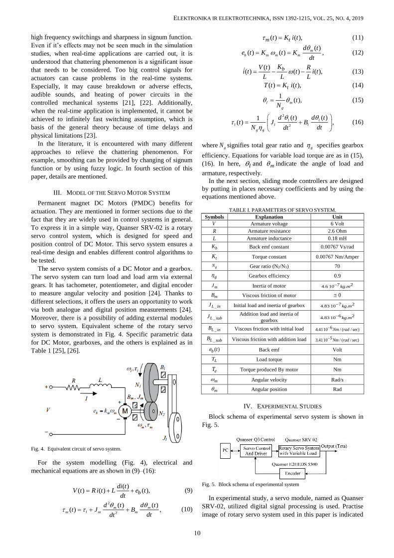
Fig. 4. Equivalent circuit of servo system.
For the system modelling (Fig. 4), electrical and
mechanical equations are as shown in (9)–(16):
( )
( ) ( ) ( ),b
di tV t R i t L e t
dt (9)
2
2
( ) ( )( ) ,m m
m l m m
d t d tt J B
dtdt
(10)
( ) ( ),m tt K i t (11)
( )
( ) ( ) ,m
b m m m
d te t K t K
dt
(12)
( )
( ) ( ) ( ),bKV t Ri t t i t
L L L (13)
( ) ( ),tT t K i t (14)
1
( ),l m
g
tN
(15)
2
2
( ) ( )1( ) ,l l
l l l
g g
d t d tt J B
N dtdt
(16)
where gN signifies total gear ratio and g specifies gearbox
efficiency. Equations for variable load torque are as in (15),
(16). In here, l and m indicate the angle of load and
armature, respectively.
In the next section, sliding mode controllers are designed
by putting in places necessary coefficients and by using the
equations mentioned above.
TABLE I. PARAMETERS OF SERVO SYSTEM.
Symbols Explanation Unit
V Armature voltage 6 Volt
R Armature resistance 2.6 Ohm
L Armature inductance 0.18 mH
bK Back emf constant 0.00767 Vs/rad
tK Torque constant 0.00767 Nm/Amper
gN Gear ratio (N2/N1) 70
g Gearbox efficiency 0.9
mJ Inertia of motor 7 24.6 10 .kg m
mB Viscous friction of motor 0
_L inJ Initial load and inertia of gearbox 7 24.83 10 .kg m
_L subJ Addition load and inertia of
gearbox 6 24.83 10 .kg m
_L inB Viscous friction with initial load 64.4110 / ( / sec)Nm rad
_L subB Viscous friction with addition load 53.4110 / ( / sec)Nm rad
( )be t Back emf Volt
LT Load torque Nm
eT Torque produced By motor Nm
m Angular velocity Rad/s
m Angular position Rad
IV. EXPERIMENTAL STUDIES
Block schema of experimental servo system is shown in
Fig. 5.
Fig. 5. Block schema of experimental system
In experimental study, a servo module, named as Quanser
SRV-02, utilized digital signal processing is used. Practise
image of rotary servo system used in this paper is indicated
10

ELEKTRONIKA IR ELEKTROTECHNIKA, ISSN 1392-1215, VOL. 25, NO. 4, 2019
in Fig. 6. In this figure, computer, servo control unit and
driver, rotary servo system, initial loaded arm, addition
loads, and the other environment components are exhibited.
It has benefitted from a data acquisition card with amplifier
named as Q3 Control PaQ-FW. Designed controllers are run
computer aided and transferred to motor system via a
software.
In this study, analyses are made by adding monitoring in
different levels by means of addition loads. Thanks to using,
firstly, an initial load and, later, for loading low and high
weighted metallic objects, three types of loading conditions
are performed and results are analysed.
Servo system can be modelled approximately as a first
order system to actualize the speed control. Additionally,
degree of the system for the position control is shown as a
second order in [24], [25]. Transfer function of the servo
system for angular velocity and angular position are
described in (17), (18):
( )
,( ) 1
s K
V s s
(17)
( ),
( ) 1
s K
V s s s
(18)
where K and are defined as steady state gain of the system
and time constant, respectively, and their values are as in
(19), (20):
( ) 1.53
,( ) 0.0254 1
s
V s s
(19)
( ) 1.53.
( ) 0.0254 1
s
V s s s
(20)
If transfer function of the system converts to state-space
model, it is obtained as follows:
0 1 0( )( )
( ),10 ( )( )
ssV s
Kss
(21)
( )
( ) [1 0] .( )
sy s
s
(22)
Fig. 6. Image of experimental system.
A. Theory 1 – Conventional SMC
In section II, the structure of conventional SMC is
mentioned. Conventional SMC is a structure of control,
which has a switching control signal with signum function as
shown in (2), (3). Additionally, theoretical implementation
of conventional SMC is expressed in this section.
The equation of state for a second order system is
generally identified as
,X AX BX Cu D E (23)
where X is specified as a primary variable in equation of the
state. Also, its first and second derivatives are X and X ,
control signal u , disturbing effect , such as friction and
load changing, and its derivative are described,
respectively. Here, A, B, and C symbolize coefficients
obtained from state equation of the system, while D and E
express unknown variable coefficients of disturbing effect. If
disturbing effects in (23) are combined with a single
variable, which is named as ,H finally, equation can be
displayed as
.X AX BX Cu H (24)
In this study, equation of the state for position control of
servo system can be created as in (25) by benefiting from
(19), (20) which is a transfer function equation of the system
( ) 39.3701 ( ) 60.2362 .s s u H (25)
While modelling in the nominal conditions, design and
resolution are made as intended when disturbance effects is
equal to zero. If dynamic states are analysed under condition
0,H namely in the nominal conditions, it is obtained as
( ) 39.3701 ( ) 60.2362 .s s u (26)
For creating a generally form, variables A and C are used.
Thus, a new equation form is turn into
( ) ( ) , 39.3701, 60.2362s A s C u A C (27)
if variables are defined as:
( ), ( ),y s u V s (28)
1
2 1
2
,
,
,
ref m
ref m
ref m
X e
X e X
X e
(29)
where , ,e e and e represents error and first and second
derivatives of error, respectively. Besides, ref and m are
defined as reference and measurement position variables.
Sliding surface and its derivative can be defined as follows:
1 2 ,ref m ref ms C X X C (30)
.ref m ref ms C (31)
If the derivative of sliding surface is equal to zero as
demonstrated in (30), which should be equal to switching
control signal, and, later, if (31) is substituted in (32),
derivation of the equation of sliding surface can be obtained
11
ELEKTRONIKA IR ELEKTROTECHNIKA, ISSN 1392-1215, VOL. 25, NO. 4, 2019
as in (33):
sgn( ),s K s (32)
sgn( ).ref m ref ms C K s (33)
If they are replaced in
sgn( ),ref ref m mC C K s (34)
which is expansion of (33), control signal u is produced as
indicated below
1
(39.3701 ) sgn( ) .60.2362
ref ref mu C C K s (35)
In experimental study, parametric coefficients are
determined as K=200 and C=70. When control signal u is
being transferred, adaptation coefficient Γ is specified as
0.15, which can be seen below
* .servou u (36)
B. Theory 2 – Modified SMC
Signum function, sgn(s), generates discontinuous control
on the sliding surface, and hence it generally produces
chattering phenomenon in control input. When intended to
chattering reduction, some modifications can be made and
different function types can be used. In this step, a
modification in the signum function is done and replaced a
smooth transition nonlinear sigmoid function, which is
indicated as follows
( ) .sw
su t K
s
(37)
While : and is in the range of 0 1 .
Moreover, it is a tuning parameter of the sigmoid function
and is selected suitable for following of ideal
performance.
Structure of control signal u produced by conventional
SMC is converted to a form such that
1
(39.3701 ) .60.2362
ref ref ms
u C C Ks
(38)
In experimental application of modified SMC, parametric
coefficients are adjusted as K=200, C=40, and =0.99.
Furthermore, adaptation coefficient Γ is designated as 0.15.
C. Theory 3 – PIDsur-SMC
In this section of theory groups, sliding surface design for
SMC is presented as with PID type surface [27], [28], which
is displayed as
1 2 3 .s e e e (39)
If it is benefitted from (29) and the second derivative of
error is replaced in (40), which is first derivative of sliding
surface, and, then (40) is equal to zero, (41) is obtained
1 2 3 .s e e e (40)
If state equation of system, which can be shown in (26), is
substituted in (40), (41) is acquired. Therefore, equivalent
control signal is defined as in (42) that edited version of
equation:
1 2 3 0,refe e A C u (41)
1 2 3 3
3
1.eq refu e e A
C
(42)
As it is indicated in
( ) ( ) ( ),eq swu t u t u t (43)
main control signal for SMC composes of two parts, such as
equivalent and switching control signal, which are also
symbolized as equ and ,swu respectively
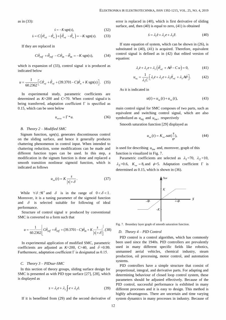
Smooth saturation function [29] displayed as
( ) . ( ),sw sw
su t K sat
(44)
is used for describing swu and, moreover, graph of this
function is visualized in Fig. 7.
Parametric coefficients are selected as 1 =70, 2 =10,
3 =0.6, 8,swK and ϕ=5. Adaptation coefficient Γ is
determined as 0.15, which is shown in (36).
Fig. 7. Boundary layer graph of smooth saturation function.
D. Theory 4 – PID Control
PID control is a control algorithm, which has commonly
been used since the 1940s. PID controllers are prevalently
used in many different specific fields like robotics,
unmanned aerial vehicles, chemical industry, steam
production, oil processing, motor control, and automation
systems.
PID controllers have a simple structure that consist of
proportional, integral, and derivative parts. For adapting and
determining behaviour of closed loop control system, these
parameters should be adjusted effectively. Because of the
PID control, successful performance is exhibited in many
different processes and it is easy to design. This method is
highly advantageous. There are uncertain and time varying
system dynamics in many processes in industry. Because of
12

ELEKTRONIKA IR ELEKTROTECHNIKA, ISSN 1392-1215, VOL. 25, NO. 4, 2019
the classical PID controllers fixed parameters, they cannot
display a good performance [7]. Thus, there is a need for a
control structure that could cope with all situations
mentioned above.
Time domain representation of PID controller is indicated
as
( )
( ) ( ) ( ) ,p d i
de tu t K e t K K e t dt
dt (45)
where ( )e t is error between input and output and, also, pK ,
,iK and dK are expressed as proportional, integral, and
derivative gain coefficients, respectively.
E. Performance Criteria
In control systems, some specific performance criteria,
which are generally used to measure and compare system
performance, are available. In this study, the evaluations are
carried out for three different criteria: Integral Square Error
(ISE), Integral Absolute Error (IAE), and Integral Time-
weighted Absolute Error (ITAE). Therefore, calculation
formulas of these criteria are expressed as follows:
2 ,ISE e dt (46)
,IAE e dt (47)
.ITAE t e dt (48)
V. TESTING STEPS AND DISCUSSION
By determining a sinusoidal reference for position
tracking, response of the motor system is analysed according
to this reference position. All graphs of performed position
tracking for designed controllers are shown in Fig. 8.
Experimental results are obtained by considering loading
condition and by comparing performance in point of ISE,
IAE, and ITAE criteria, which is explained as in Table II. As
it is understood from the graphs, computing of performance
criteria is done for 2.5 s that period of the reference signal.
According to Table II, the best performance is produced by
PIDsur-SMC for all loading conditions, and, later, M-SMC
and SMC produces, respectively. In this study, generated
graphs indicate response of system for the first 5 s.
Fig. 8. Change of the position tracking under initial load.
In Figure 8, position-time graph of servo system for four
type controllers under initial load is drawn. Because of data
is close to each other, a zoomed image is demonstrated in
Fig. 9. It can be seen that all three different SMC controllers
actually produce quite successful results. However, if a
comparison is made among them, PIDsur-SMC`s tracking
trajectory is the nearest to reference position. However, PID
controller has the worst tracking compared the others. Also,
according to controllers, position error of servo system
under initial load is demonstrated in Fig. 10. PIDsur-SMC
can track the desired reference trajectory at least error.
Additionally, the change of the sliding surface for three
SMC structures under initial conditions are indicated in Fig.
11. The sliding surface interval of the PIDsur-SMC in Fig.11
is the narrowest and nearest interval on the zero axis.
Considering the interval of sliding surface, it can be
mentioned that the controller displays more succeeded
results for the narrowest range s . Moreover, the change
of the control signal transferred to the system by different
controllers under initial load is indicated in Fig. 12.
Fig. 9. Change of the zoomed position under initial load.
Fig. 10. Change of the error under initial load.
Fig. 11. Change of the control signal u under initial load.
Similarly, results for controllers under low load are
demonstrated in Fig. 13–Fig. 16. When the changes of the
error in Fig. 14 are analysed, amount of the error is at least
in PIDsur-SMC. In conventional SMC, error changes in a
wide range. It is demonstrated that error for PID control is
13

ELEKTRONIKA IR ELEKTROTECHNIKA, ISSN 1392-1215, VOL. 25, NO. 4, 2019
more than the other controllers. Increasing error amount
means that position tracking has deteriorated. Moreover, in
Fig. 16, it is shown how to change sliding surface for the
controllers. Here, the nearest movement to sliding surface is
performed by PIDsur-SMC, but sliding in conventional
SMC is taken place in a large scale.
Fig. 12. Change of the sliding surface under initial load.
Fig. 13. Change of the position tracking under low load.
Fig. 14. Change of the error under low load.
Fig. 15. Change of the control signal under low load.
In Figures 17–20, results of controllers under high load
condition are indicated. It is observed that graphs are
composed parallely with previous results. Especially, if
changes of error and sliding surface are analysed,
performance comparisons for controllers can be made. Thus,
superiority rating for controllers can be made as PIDsur-
SMC, M-SMC, and conventional SMC, respectively.
TABLE II. COMPARISONS OF CONTROLLERS.
Load Criteria PID SMC M-SMC PIDsur-
SMC
Initial ISE 35.72 10-
5
6.765 10-
5
1.108 10-
5 0.6535 10-5
Initial IAE 0.02754 0.01072 0.004389 0.003481
Initial ITAE 0.1053 0.04037 0.01702 0.01302
Low ISE 48.85 10-
5
7.289 10-
5
3.405 10-
5 1.005 10-5
Low IAE 0.02886 0.01202 0.007467 0.004145
Low ITAE 0.112 0.04408 0.03002 0.01531
High ISE 58.97 10-
5
8.755 10-
5
4.903 10-
5 1.506 10-5
High IAE 0.03091 0.01323 0.008919 0.004861
High ITAE 0.1205 0.04928 0.03626 0.01816
Fig. 16. Change of the sliding surface under low load.
Fig. 17. Change of the position tracking under high load.
Fig. 18. Change of the error under high load.
14

ELEKTRONIKA IR ELEKTROTECHNIKA, ISSN 1392-1215, VOL. 25, NO. 4, 2019
Fig. 19. Change of the control signal under high load.
Fig. 20. Change of the sliding surface under high load.
VI. CONCLUSIONS
In this study, three different type sliding mode controllers
are designed for position control of DC servo system, which
is an extremely important issue in the control systems.
Performance of controllers are compared after implementing
designed controllers to DC servo system under different load
conditions. Conventional SMC is a method that produces
chattering phenomenon. M-SMC is designed by modifying
switching function and it relieves greatly this problem. In
addition, it gives better results when compared to previous
control structure. In the last control structure, an alteration is
made in sliding surface, which is the basic building block of
SMC. It is understood that a controller running more stable
and better performance is generated. In experimental results,
although it is concluded that three methods can be run on
system real-time, it is shown that M-SMC and PIDsur-SMC
run more stable without vibration and error. In motor control
application, elimination of vibration is so important due to
the fact that it may cause deterioration of mechanical system.
In sensitive running conditions as in some robotic
applications, uncertainties, sudden changes, time-varying
load changes and precise position tracking, application of
SMC method provides many advantages.
ACKNOWLEDMENT
Authors are grateful to Selcuk University Scientific
Research Projects Office, Academic Training Program and
Rac-Lab (www.rac-lab.com) for providing this study.
CONFLICT OF INTEREST
The authors declare no conflict of interest.
REFERENCES
[1] M. K. Khan, “Design and application of second order sliding mode
control algorithms”, Ph.D. dissertation, Department of Engineering,
University of Leicester, 2003.
[2] D. Yulin, “The analysis and implement of PLC- based PI control for
the permanent magnet DC motor”, in Proc. 2nd International Conf.
Communication Systems, Networks and Applications, Hong Kong,
2010, pp. 448–451. DOI: 10.1109/ICCSNA.2010.5588973.
[3] T. R. Dil Kumar and S. J. Mija, “Design and performance evaluation
of robust SMC schemes for speed control of DC motor”, in Proc.
International Conf. Advanced Communication Control and
Computing Technologies, Ramanathapuram, 2014, pp. 88-92. DOI:
10.1109/ICACCCT.2014.7019235.
[4] S. Kurode, B. Tamhane, Dharmveer, and P. Dixit, “Robust control
with simultaneous state and disturbance estimation using sliding
modes”, in Proc. 12th International Workshop on Variable Structure
Systems (VSS), Mumbai, Maharashtra, 2012, pp. 237–242. DOI:
10.1109/VSS.2012.6163508.
[5] A. A. Al Rawi, R. B. Ahmad, and H. H. Tahir, “Chatter-less sliding-
mode controller for DC motor”, in Proc. IEEE Student Conf.
Research and Development, Putrajaya, 2013, pp. 54–59. DOI:
10.1109/SCOReD.2013.7002540.
[6] A. K. Kadam, D. D. Ray, S. R. Shimjith, P. D. Shendge, and S. B.
Phadke, “Time delay controller combined with sliding mode for DC
motor position control: Experimental validation on Quanser QET”, in
Proc. International Conf. Power, Energy and Control, Sri
Rangalatchum Dindigul, 2013, pp. 449–453. DOI:
10.1109/ICPEC.2013.6527698.
[7] K. Nouri, R. Dhaouadi, and N. B. Braiek, “Adaptive control of a
nonlinear dc motor drive using recurrent neural networks”, Applied
Soft Computing, vol. 8, no. 1, pp. 371–382, 2008. DOI:
10.1016/j.asoc.2007.03.002.
[8] S. K. Gupta and P. Varshney, “Fractional fuzzy PID controller for
speed control of DC motor”, in Proc. 3rd International Conf.
Advances in Computing and Communications, Cochin, 2013, pp. 1–
4. DOI: 10.1109/ICACC.2013.7.
[9] J. Velagic and A. Galijasevic, “Design of fuzzy logic control of
permanent magnet DC motor under real constraints and
disturbances”, in Proc. 3rd International Conf. Control Applications
& Intelligent Control, Saint Petersburg, 2009, pp. 461–466. DOI:
10.1109/CCA.2009.5281099.
[10] E. Buzi and P. Marango, “A Comparison of conventional and
nonconventional methods of DC motor speed control”, in Proc. 15th
IFAC Workshop on International Stability, Technology, and Culture,
vol. 46, no. 8, 2013, pp. 50–53. DOI: 10.3182/20130606-3-XK-
4037.00054.
[11] E. H. Dursun and A. Durdu, “Speed control of a DC motor with
variable load using sliding mode control”, International Journal of
Computer and Electrical Engineering, vol. 8, no. 3, pp. 219–226,
2016. DOI: 10.17706/ijcee.2016.8.3.219-226.
[12] D. Kowalów, M. Patan, W. Paszke, and A. Romanek, “Sequential
design for model calibration in iterative learning control of DC
motor”, in Proc. 20th International Conf. Methods and Models in
Automation and Robotics, Miedzyzdroje, 2015, pp. 794–799. DOI:
10.1109/MMAR.2015.7283977.
[13] J.-J. E. Slotine and W. Li, Applied Nonlinear Control. Englewood
Cliffs, New Jersey, Prentice Hall, 1991.
[14] V. Utkin, “Variable structure systems with sliding modes”, IEEE
Transactions on Automatic Control, vol. 22, no. 2, pp. 212–222,
1977. DOI: 10.1109/TAC.1977.1101446.
[15] C. Edwards and S. K. Spurgeon, Sliding Mode Control: Theory and
Applications, Taylor & Francis, 1998. DOI:
10.1201/9781498701822.
[16] V. Utkin, J. Güldner, and J. Shi, Sliding Mode Control in
Electromechanical Systems, Taylor & Francis, 1999.
[17] B. Soysal, “Real-time control of an automated guided vehicle using a
continuous mode of sliding mode control”, Turk J Elec Eng & Comp
Sci, vol. 22, pp. 1298––1306, 2014. DOI: 10.3906/elk-1211-130.
[18] J. Y. Hung, W. Gao and J,. C. Hung, “Variable structure control: A
survey”, IEEE Transactions on Industrial Electronics, vol. 40, no. 1,
pp. 2–22, 1993. DOI: 10.1109/41.184817.
[19] G. Monsees, “Discrete-Time Sliding Mode Control”, Ph.D.
dissertation, Delft University of Technology, 2002. DOI:
10.23919/ECC.2001.7076437.
[20] I. Boiko, L. Fridman, R. Iriarte, A. Pisano, and E. Usai, “Parameter
15

ELEKTRONIKA IR ELEKTROTECHNIKA, ISSN 1392-1215, VOL. 25, NO. 4, 2019
tuning of second-order sliding mode controllers for linear plants with
dynamic actuators”, Automatica, vol. 42, no. 5, pp. 833–839, 2006.
DOI: 10.1016/j.automatica.2006.01.009.
[21] A. Pisano, “Second Order Sliding Modes: Theory and Applications”,
Ph.D. dissertation, Dipartimento di Ingegneria Elettrica ed
Elettronica, Universit´a degli Studi di Cagliari, 2000.
[22] H. Brandtstadter, “Sliding Mode Control of Electromechanical
Systems”, Ph.D. dissertation, Technische Universitat München, 2009.
[23] N. T. Tai and K. K. Ahn, “A RBF neural network sliding mode
controller for SMA actuator”, International Journal of Control,
Automation and Systems, vol. 8, no. 6, pp. 1296–1305, 2010. DOI:
10.1007/s12555-010-0615-8.
[24] A. Brindha, S. Balamurugan, and P. Venkatesh, “Real time
experiment to determine transfer function of Quanser servo plant”, in
Proc. International Conf. Recent Advancements in Electrical,
Electronics and Control Engineering, Sivakasi, 2011, pp. 253–257.
DOI: 10.1109/ICONRAEeCE.2011.6129731.
[25] SRV02 Rotary Servo Base Unit Setup and Configuration, Quanser,
ed. Canada: Quanser Inc., 2011.
[26] Ö. Aydoğdu and Ö. Alkan, “Adaptive control of a time-varying rotary
servo system using a fuzzy model reference learning controller with
variable adaptation gain”, Turk J Elec Eng & Comp Sci, vol. 21,
pp. 2168–2180, 2013. DOI: 10.3906/elk-1201-115.
[27] İ. Eker and Ş. A. Akınal, “Sliding mode control with integral
augmented sliding surface: Design and experimental application to an
electromechanical system”, Electrical Engineering, vol. 90, no. 3,
pp. 189–197, 2008. DOI: 10.1007/s00202-007-0073-3.
[28] Y. Li and Q. Xu, “Adaptive sliding mode control with perturbation
estimation and PID sliding surface for motion tracking of a piezo-
driven micromanipulator”, IEEE Transactions on Control Systems
Technology, vol. 18, no. 4, pp. 798–810, 2010. DOI:
10.1109/TCST.2009.2028878.
[29] R. M. Nagarale and B. M. Patre, “Exponential function based fuzzy
sliding mode control of uncertain nonlinear systems”, International
Journal of Dynamics and Control, vol. 4, no. 1, pp. 67–75, 2016.
DOI: 10.1007/s40435-014-0117-2.
16