Embed Size (px)
Citation preview
Chinese Journal of Aeronautics, 2013,26(4): 967–975
Chinese Society of Aeronautics and Astronautics& Beihang University
Chinese Journal of Aeronautics
Sliding mode control of reaction flywheel-based
brushless DC motor with buck converter
Liu Gang *, Zhang Cong
School of Instrumentation Science and Opto-electronics Engineering, Beihang University, Beijing 100191, China
Received 21 March 2012; revised 29 May 2012; accepted 18 July 2012Available online 30 April 2013
*
E
co
Pe
10
ht
KEYWORDS
DC–DC converter;
Flywheels;
State averaging model;
Sliding mode control;
Sliding surface;
Topology
Corresponding author. Tel.
-mail addresses: liugang@b
m (C. Zhang).
er review under responsibilit
Production an
00-9361 ª 2013 Production
tp://dx.doi.org/10.1016/j.cja.2
: +86 10
uaa.edu.c
y of Edit
d hostin
and hosti
013.04.0
Abstract Reaction flywheel is a significant actuator for satellites’ attitude control. To improve out-
put torque and rotational speed accuracy for reaction flywheel, this paper reviews the modeling and
control approaches of DC–DC converters and presents an application of the variable structure sys-
tem theory with associated sliding regimes. Firstly, the topology of reaction flywheel is constructed.
The small signal linearization process for a buck converter is illustrated. Then, based on the state
averaging models and reaching qualification expressed by the Lee derivative, the general results of
the sliding mode control (SMC) are analyzed. The analytical equivalent control laws for reaction
flywheel are deduced detailedly by selecting various sliding surfaces at electromotion, energy con-
sumption braking, reverse connection braking stages. Finally, numerical and experimental examples
are presented for illustrative purposes. The results demonstrate that favorable agreement is estab-
lished between the simulations and experiments. The proposed control strategy achieves preferable
rotational speed regulation, strong rejection of modest disturbances, and high-precision output tor-
que and rotational speed tracking abilities.ª 2013 Production and hosting by Elsevier Ltd. on behalf of CSAA & BUAA.
Open access under CC BY-NC-ND license.1. Introduction
With increasing complications and varieties of satellites, the
requirement for attitude control becomes higher. As a signifi-cant actuator, a reaction flywheel has high output precisionof angular momentum, strong anti-interference ability, and
fast response, whose output torque accuracy directly affects
82317396.
n (G. Liu), [email protected]
orial Committee of CJA.
g by Elsevier
ng by Elsevier Ltd. on behalf of C
38
attitude control precision. Thus, how to improve the stabiliza-tion and control precision for angular momentum is a keyissue and urgent to be solved. The reaction flywheel can be re-
garded as a motor with a biggish moment of inertia. For thedrive motor of reaction flywheel domestic and overseas, thebrushless DC motor (BLDCM) is utilized widely with a rela-
tively wide range of rotational speed, and the rotational speedregulation requires that the motor’s line voltage changes withthe rotational speed. Therefore, a voltage-mode controlled
buck converter is mainly applied as a typical DC–DC con-verter. As is known, the DC–DC converter is a highly nonlin-ear plant with abundant dynamical behaviors, such as the
Hopf bifurcation,1 period doubling bifurcation,2 border colli-sion bifurcation,3 tangent bifurcation,4 coexisting attractors,5
etc. The major difficulty in controlling the DC–DC converteris the exact modeling.
SAA & BUAA. Open access under CC BY-NC-ND license.

968 G. Liu, C. Zhang
At present, the modeling approaches for DC–DC convert-ers are generally divided into two types: one based on smallsignal analysis and the other using large signal analysis. The
small signal analysis consists of the state-space averaging ap-proach6 and the averaged equivalent circuit approach.7 How-ever, the large signal analysis is complicated and also
classified into two categories: one is based on the state-spaceaveraging or circuit-average method, such as the phase planemethod,8 the switching signal flow graph approach,9 etc.; the
other uses state variables ripple determination, like the ex-tended ripple analysis,10 the nth harmonic three terminal mod-el,11 the Krylov Bogoliubov Mitropolskii (KBM) method,12
the Volterra series determination,13 the describing function
method,14 etc. Anyway, most control strategies are still basedon the state-space averaging model or the linearization smallsignal model.
The DC–DC converter constitutes a closed-loop systemwith power stage and control circuit, whose topology deter-mines the performance together with control strategy. Based
on the average model, various control strategies have beeninvestigated using feedback linearization, quasi-linear ap-proach,15 optimal control,16 passivity techniques,17 flatness
methods,18 H1 control,19,20 linear multiloop control,21 linearquadratic regulator (LQR) based control,22 adaptive pole-zeroposition technique,23 fuzzy control,24,25 backstepping con-trol,26 etc. From the viewpoint of automatic control, the
switching converter represents an interesting case study as atypical variable structure system (VSS). Especially, Sira-Ramirez27established an ideal equivalence among the pulse
width modulation (PWM) and variable structure feedback op-tions for nonlinear systems. Moreover, various sliding modestrategies have been developed extensively.28–32 The sliding
surface is made ideally invariant with respect to high-frequencyswitch controlled state trajectories. In order to improve theoutput torque accuracy and rotational speed tracking preci-
sion, the sliding mode control (SMC) technique of VSSs is ap-plied to the reaction flywheel.
This paper is organized as follows: based on the state-spaceaveraging approach, Section 2 analyzes the equivalent topolo-
Fig. 1 Equivalent topolo
gies of reaction flywheel and obtains its state averaging modelsat electromotion, energy consumption braking, and reverseconnection braking stages, respectively; Section 3 briefly pre-
sents the general results of SMC for a typical variable structuresystem like the adopted buck converter; Section 4 is devoted toapply the results of Sections 2 and 3 to deduce detailedly the
analytical equivalent control laws at different operation stagesby selecting various sliding surfaces; Sections 5 and 6 describesimulations and experiments performed to verify the proposed
strategy; Section 7 summarizes the conclusions.
2. Topology of reaction flywheel
The reaction flywheel is used to adjust the satellite attitude orcounteract the disturbance torque to maintain the attitudestabilization with a reaction torque, which is produced by
the motor’s acceleration or deceleration. Fig. 1 shows theequivalent topology of reaction flywheel based on the BLDCMwith a buck converter:
In Fig. 1, UDC is power supply; VTp (p = 1 – 6) are com-
mutation switching transistors, VT7 is a buck converter andVT8 an energy consumption braking transistor; VDq(q = 1 – 8) are anti-paralleled diodes; VD is a freewheeling
diode, L a filter inductor, C a filter capacitor, i the input cur-rent of the inductor, im the line current of the motor, v capac-itor voltage, Rp a power resistor, and Rs an accurate sampling
resistor; Rm and Lm are equivalent resistor and inductor ofwindings, respectively; ea, eb, and ec are the back electromo-tive force (EMF) of a, b, and c phase windings, respectively.
With 3-phase 6-states wye-connected, each switchingtransistor of the upper and lower bridge is turned on simulta-neously. Neglect the effect of commutation and assume thatthe 3-phase windings are symmetric with the same electric
parameters.Taking VT7-ON and VT8-OFF for example, the small sig-
nal linearization process for the adopted buck converter is
illustrated as follows. Considering the buck converter only,using the continuous characteristic of inductor current andcapacitor voltage yields
gy of reaction flywheel.
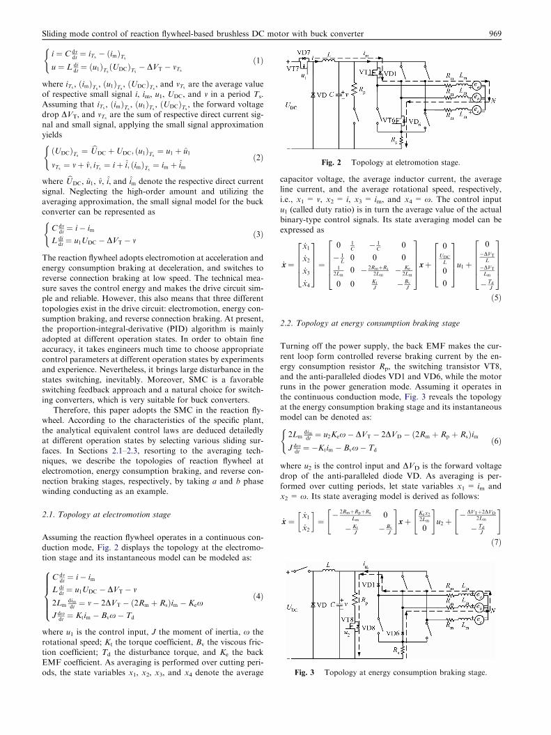
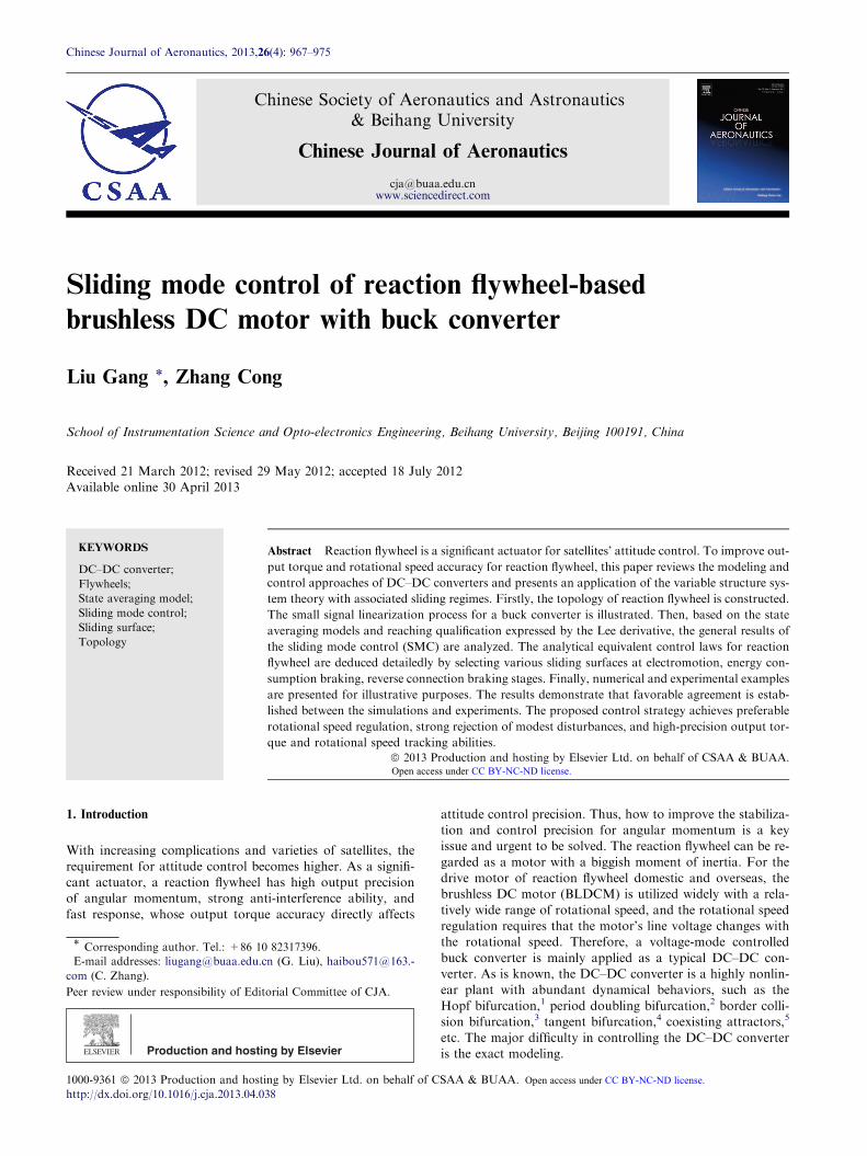
Fig. 2 Topology at eletromotion stage.
Fig. 3 Topology at energy consumption braking stage.
Sliding mode control of reaction flywheel-based brushless DC motor with buck converter 969
i ¼ C dvdt¼ iTs
� ðimÞTs
u ¼ L didt¼ ðu1ÞTs
ðUDCÞTs� DVT � vTs
(ð1Þ
where iTs, ðimÞTs
, ðu1ÞTs, ðUDCÞTs
, and vTsare the average value
of respective small signal i, im, u1, UDC, and v in a period Ts.
Assuming that iTs, ðimÞTs
, ðu1ÞTs, ðUDCÞTs
, the forward voltagedrop DVT, and vTs
are the sum of respective direct current sig-nal and small signal, applying the small signal approximationyields
ðUDCÞTs¼ bUDC þUDC; ðu1ÞTs
¼ u1 þ u1
vTs¼ vþ v; iTs
¼ iþ i; ðimÞTs¼ im þ im
(ð2Þ
where bUDC, u1, v, i, and im denote the respective direct currentsignal. Neglecting the high-order amount and utilizing the
averaging approximation, the small signal model for the buckconverter can be represented as
C dvdt¼ i� im
L didt¼ u1UDC � DVT � v
(ð3Þ
The reaction flywheel adopts electromotion at acceleration andenergy consumption braking at deceleration, and switches to
reverse connection braking at low speed. The technical mea-sure saves the control energy and makes the drive circuit sim-ple and reliable. However, this also means that three different
topologies exist in the drive circuit: electromotion, energy con-sumption braking, and reverse connection braking. At present,the proportion-integral-derivative (PID) algorithm is mainly
adopted at different operation states. In order to obtain fineaccuracy, it takes engineers much time to choose appropriatecontrol parameters at different operation states by experiments
and experience. Nevertheless, it brings large disturbance in thestates switching, inevitably. Moreover, SMC is a favorableswitching feedback approach and a natural choice for switch-ing converters, which is very suitable for buck converters.
Therefore, this paper adopts the SMC in the reaction fly-wheel. According to the characteristics of the specific plant,the analytical equivalent control laws are deduced detailedly
at different operation states by selecting various sliding sur-faces. In Sections 2.1–2.3, resorting to the averaging tech-niques, we describe the topologies of reaction flywheel at
electromotion, energy consumption braking, and reverse con-nection braking stages, respectively, by taking a and b phasewinding conducting as an example.
2.1. Topology at electromotion stage
Assuming the reaction flywheel operates in a continuous con-duction mode, Fig. 2 displays the topology at the electromo-
tion stage and its instantaneous model can be modeled as:
C dvdt¼ i� im
L didt¼ u1UDC � DVT � v
2Lmdimdt¼ v� 2DVT � ð2Rm þ RsÞim � Kex
J dxdt¼ Ktim � Bvx� Td
8>>>><>>>>: ð4Þ
where u1 is the control input, J the moment of inertia, x the
rotational speed; Kt the torque coefficient, Bv the viscous fric-tion coefficient; Td the disturbance torque, and Ke the backEMF coefficient. As averaging is performed over cutting peri-ods, the state variables x1, x2, x3, and x4 denote the average
capacitor voltage, the average inductor current, the averageline current, and the average rotational speed, respectively,i.e., x1 = v, x2 = i, x3 = im, and x4 = x. The control input
u1 (called duty ratio) is in turn the average value of the actualbinary-type control signals. Its state averaging model can beexpressed as
_x¼
_x1
_x2
_x3
_x4
2666437775¼
0 1C
� 1C
0
� 1L
0 0 01
2Lm0 � 2RmþRs
2Lm� Ke
2Lm
0 0 Kt
J�Bv
J
266664377775xþ
0UDC
L
0
0
2666437775u1þ
0�DVT
L
�DVT
Lm
�Td
J
266664377775ð5Þ
2.2. Topology at energy consumption braking stage
Turning off the power supply, the back EMF makes the cur-
rent loop form controlled reverse braking current by the en-ergy consumption resistor Rp, the switching transistor VT8,and the anti-paralleled diodes VD1 and VD6, while the motorruns in the power generation mode. Assuming it operates in
the continuous conduction mode, Fig. 3 reveals the topologyat the energy consumption braking stage and its instantaneousmodel can be denoted as:
2Lmdimdt¼ u2Kex� DVT � 2DVD � ð2Rm þ Rp þ RsÞim
J dxdt¼ �Ktim � Bvx� Td
(ð6Þ
where u2 is the control input and DVD is the forward voltagedrop of the anti-paralleled diode VD. As averaging is per-formed over cutting periods, let state variables x1 = im and
x2 = x. Its state averaging model is derived as follows:
_x ¼_x1
_x2
� �¼� 2RmþRpþRs
Lm0
� Kt
J� Bv
J
" #xþ
Kex22Lm
0
" #u2 þ
� DVTþ2DVD
2Lm
� Td
J
" #ð7Þ

Fig. 4 Topology at reverse connection braking stage.
970 G. Liu, C. Zhang
2.3. Topology at reverse connection braking stage
The braking power is provided with power supply and thebuck converter outputs constant capacitor voltage v at the re-verse connection braking stage, which must satisfy
v> Kex + DVT to eliminate the interphase internal circula-tion of windings. Besides, the commutation switching transis-tors VT1 and VT6 execute pulse width modulation inrespective conduction region to regulate the braking torque
as in Fig. 4 and its instantaneous model can be derived as
C dvdt¼ i� im
L didt¼ u4UDC � DVT � v
2Lmdimdt¼ u3ðvþ KexÞ � 2DVT � ð2Rm þ RsÞim
J dxdt¼ �Ktim � Bvx� Td
8>>>><>>>>: ð8Þ
As averaging is performed over cutting periods, let state vari-
ables x1 = v, x2 = i, x3 = im, and x4 = x. Its state averagingmodel is described as
_x ¼
_x1
_x2
_x3
_x4
2666437775 ¼
0 1C
� 1C
0
� 1L
0 0 0
0 0 � 2RmþRs
2Lm0
0 0 � Kt
J� Bv
J
266664377775xþ
0UDC
L
0
0
2666437775u4
þ
0
0x1þKex4
2Lm
0
2666437775u3 þ
0�DVT
L
�DVT
Lm
� Td
J
266664377775 ð9Þ
where u3 and u4 are the control inputs.
The output torque To of the reaction flywheel is propor-tional to the derivative of rotational speed x, i.e., To ¼ J _x.According to the action and reaction law, the reaction torqueon the satellite is equal to To, but with an opposite sign.
3. General results of SMC
Sira-Ramirez27 presented a differential geometric approach for
design of sliding modes in nonlinear VSSs, coordinate-freecharacterizations of local existence conditions for sliding re-gimes, and a geometric reformulation of some of its most sali-
ent features. Moreover, he also demonstrated the existence ofan ideal equivalence among SMC and PWM control responsein nonlinear dynamical systems.33 Similarly, consider the fol-
lowing smooth nonlinear system:
_x ¼ fðxÞ þ gðxÞu ð10Þ
where x e X, an open set of Rn, the scalar control input u:
Rn fi R is a feedback control function, while f and g are
smooth local vector fields defined on X with g(x) „ 0 and"x e X. Let s denote a smooth real value of x defined by
s:X fi R. The level set S= {x e Rn: s(x) = 0}, defines a locally
regular n�1 dimensional sub-manifold, addressed as the slid-ing surface.
Without loss of generality, a SMC control law that accom-
plishes the surface reachability is obtained by letting u take oneof two possible values, namely 0 or 1. According to Ref. 34, ucan be selected as:
u ¼0:5ð1þ sgnðsÞÞ Lgs ¼ hds; gi < 0
0:5ð1� sgnðsÞÞ Lgs ¼ hds; gi > 0
�ð11Þ
where ds denotes the one-form corresponding to the gradient
of s(x), that is assumed to be nonzero in X except <,> isthe standard scalar product. In the method of equivalent con-trol, ideal sliding motions are described by using the manifold
invariance conditions s = 0 and Lfþueqgs ¼ 0, where ueq is asmooth equivalent control law, explicitly given by:27
ueq ¼ �Lfs
Lgs¼ � hds; fihds; gi ¼ �
ds
dxf
� �ds
dxg
� ��1ð12Þ
A necessary and sufficient condition for the equivalent control
to be well defined is represented by the transversality conditionLgs „ 0.33 Meanwhile, a sliding regime exists on S if and only iffor all x e S the equivalent control satisfies 0 < ueq < 1.34
4. Equivalent control law design
In this paper, the output torque of reaction flywheel is imple-
mented by controlling the rotational speed of the BLDCM.The BLDCM adopts 3-phase full bridge topology with a buckconverter. In order to achieve 4-quadrant operation for the
BLDCM, the rotational speed is changed by regulating theduty ratio for the buck converter’s switching diodes VT7 andVT8. In the buck converter, the duty ratio belongs to controllimited situation. Therefore, the design of the buck converter
controller focuses on selection of the sliding surface and deri-vation of the sliding mode control law for u1, u2, u3, and u4at different quadrants. The sliding surface is important to
the control precision of the reaction flywheel. The sliding sur-face must make sure that all the measurable states are includedin the sliding surface, and the actual rotational speed can track
the rotational speed command with first-order transitiondynamic.
By searching a dominating set, the SMC of reaction fly-
wheel utilizes the states discrepancy of the buck converter toreach the sliding surface as quickly as possible during the con-tinuous conduction mode, which satisfies the asymptotic sta-bility criteria with preferable dynamics performance.
However, the control input is 0 or 1, which is confined strictly.Therefore, most SMC designs concentrate on the selection ofsliding surfaces. In this section, we deduce detailedly the ana-
lytical equivalent control laws at electromotion, energy con-sumption braking, and reverse connection braking stages byselecting different sliding surfaces, respectively.
In general, we should choose sliding surfaces and appropri-ate coefficients to guarantee the sliding mode stability andfavorable dynamic performance based on the anticipant
control object. According to the state averaging models, the

Sliding mode control of reaction flywheel-based brushless DC motor with buck converter 971
sliding surfaces are selected as s1(x), s2(x), and s3(x) at electro-motion, energy consumption braking, and reverse connectionbraking stages, respectively.
4.1. Equivalent control law at electromotion stage
According to Eq. (5), we have
f1ðxÞ ¼
0 1C
� 1C
0
� 1L
0 0 01
2Lm0 � 2RmþRs
2Lm� Ke
2Lm
0 0 Kt
J� Bv
J
2666437775x; g1ðxÞ ¼
0UDC
L
0
0
26643775 ð13Þ
Here, the sliding surface is selected as:
s1ðxÞ ¼ ½c1ðvr � x1Þ þ ð _vr � _x1Þ� þ ½c2ðimr � x3Þ þ ð _imr � _x3Þ�þ ½c3ðxr � x4Þ þ ð _xr � _x4Þ� ð14Þ
where c1, c2, and c3 are control parameters, vr is the referenced
capacitor voltage, imr the referenced line current, and xr thereferenced rotational speed. Assuming vr, imr, and xr are con-stants in the continuous conduction mode, then
s1ðxÞ ¼ � c1 þ1
2Lm
� �x1 �
1
Cx2 � c2 �
1
C� 2Rm þRs
2Lm
þKt
J
� �x3
� c3 �Ke
2Lm
�Bv
J
� �x4
þ c1vrþ c2imr þ c3xrþDVT
Lm
þTd
J
� �ð15Þ
Let A1 ¼ c1 þ 12Lm
;A2 ¼ 1C, A3 ¼ c2 � 1
C� 2RmþRs
2Lmþ Kt
J, A4 ¼ c3�
Ke
2Lm� Bv
J, and D ¼ c1vr þ c2imr þ c3xr þ DVT
Lmþ Td
J. Eq. (15) can
be simplified as s1(x) = � A1x1 � A2x2 � A3x3 � A4x4 + D .With Eqs. (11) and (13), then
Lg1s ¼ hds; g1i ¼os1ox1
os1ox2
os1ox3
os1ox4
h ig1ðxÞ ¼ �
UDC
CL< 0 ð16Þ
The control input u1 can be specified as u1 = 0.5(1 + sgn(s)).By exploiting Eqs. (12) and (13), we have
u1eq ¼ �Lf1s
Lg1s¼ � CL
UDC
� �A3
2Lm
� A2
L
� �x1 þ
A1
Cx2
�þ KtA4
J� A1
C� 2Rm þ Rsð ÞA3
2Lm
� �x3 �
KeA3
2Lm
þ BvA4
J
� �x4
�ð17Þ
Let s1(x) = 0, then x2 ¼ � A1
A2x1 � A3
A2x3 � A4
A2x4 þ D
A2. Substitut-
ing this x2 expression into Eq. (17) yields
u1eq ¼ �CL
UDC
�A3
2Lm
� A2
L� A2
1
CA2
�x1
�þ KtA4
J� A1
C� A1A3
CA2
� 2Rm þ Rsð ÞA3
2Lm
� �x3
� KeA3
2Lm
þ BvA4
Jþ A1A4
CA2
� �x4 þ
DA1
CA2
�ð18Þ
4.2. Equivalent control law at energy consumption braking stage
According to Eq. (7), we have
f 2ðxÞ ¼� 2RmþRpþRs
Lm0
� Kt
J� Bv
J
" #x; g2ðxÞ ¼
Kex22Lm
0
" #ð19Þ
Here, the sliding surface is selected as:
s2ðxÞ ¼ c1ðxr � x2Þ þ ð _xr � _x2Þ ð20Þ
Assuming xr is a constant, then
s2ðxÞ ¼Kt
Jx1 þ �c1 þ
Bv
J
� �x2 þ
Td
Jð21Þ
With Eqs. (19) and (21), then
Lg2s ¼ hds; g2i ¼KtKex2
2JLm
> 0 ð22Þ
The control input u2 can be described as u2 = 0.5(1 � sgn(s)).By exploiting Eqs. (19) and (22), the following equation holds:
u2eq ¼ �Lf 2
s
Lg2s¼ 2Lm
KtKex2
� JKtð2Rm þ Rp þ RsÞ � c1KtJLm þ KtBvLm
JLm
x1
�þBvðBv � c1JÞ
Jx2
�ð23Þ
Let s2(x) = 0, then x1 ¼ � JKt�c1 þ Bv
J
� x2 þ Td
J
�. Substituting
this x1 expression into Eq. (23) yields
u2eq ¼2½JKtð2Rm þ Rp þ RsÞ � c1KtJLm þ KtBvLm�x1
JKtKex2
þ 2LmBvðBv � c1JÞJKtKe
ð24Þ
4.3. Equivalent control law at reverse connection braking stage
According to Eq. (9), we have
f3ðxÞ ¼
0 1C
� 1C
0
� 1L
0 0 0
0 0 � 2RmþRs
2Lm0
0 0 � Kt
J� Bv
J
2666664
3777775x
gðxÞ ¼ g4ðxÞ þ g3ðxÞ ¼
0
UDC
L
0
0
266664377775þ
0
0
x1þKex42Lm
0
266664377775
8>>>>>>>>>>>>>>>>><>>>>>>>>>>>>>>>>>:
ð25Þ
Here, the sliding surface is selected as:
s3ðxÞ ¼ ½c1ðvr � x1Þ þ ð _vr � _x1Þ� þ ½c2ðxr � x4Þ þ ð _xr � _x4Þ�ð26Þ
Assuming that vr and xr are constants, then
s3ðxÞ ¼ �c1x1 �1
Cx2 þ
1
Cþ Kt
J
� �x3 � c2 �
Bv
J
� �x4
þ c1vr þ c2xr þTd
J
� �ð27Þ
With Eqs. (11) and (27), then
Lg4s ¼ hds; g4i ¼ �UDC
CL< 0 ð28Þ
The control input u4 can be described as u4 = 0.5(1 + sgn(s)).By exploiting Eqs. (12) and (25), we have

Fig. 5 Simulation model.
Table 1 Key electric parameters.
Table 2 Four-quadrant operation control logic of reaction
flywheel BLDCM.
Tr Rotational
direction
Rotational
speed(r/min)
Operation stage
+ Counterclockwise 0–5000 Electromotion stage
Clockwise �5000 to �3000 Energy consumption
braking stage
�3000–0 Reverse connection
braking stage
� Clockwise 0 to �5000 Electromotion stage
Counterclockwise 5000–3000 Energy consumption
braking stage
3000–0 Reverse connection
braking stage
972 G. Liu, C. Zhang
u4eq¼�Lf 3
s
Lg4 s¼UDC
CL
1
CLx1�
c1Cx2þ
Bvðc2J�BvÞJ2
x4
���2c1J
2LmþJð2RmþRsÞðJþKtCÞ�2KtCLmðc2J�BvÞ2CJ2Lm
x3
�ð29Þ
Let s3(x) = 0, then x2 ¼ �c1Cx1 þ ð1þ KtCJÞx3 �Cðc2 � Bv
JÞx4þ
Cðc1vr þ c2xr þ Td
JÞ. Substituting the x2 expression into Eq. (29)
yields
u4eq ¼CL
UDC
1
CLþc21
� �x1
��Jð2RmþRsÞðJþKtCÞ�2KtCLmðc2J�BvÞþ2c1KtCJLm
2CJ2Lm
x3
þBvðc2J�BvÞþ c1Jðc2J�BvÞJ2
x4�c1 c1vrþc2xrþTd
J
� ��ð30Þ
Using the same procedure, we have
Lg3s ¼ hds; g3i ¼1
Cþ Kt
J
� �x1 þ Kex4
2Lm
� �> 0 ð31Þ
The control input u3 can be denoted as u3 = 0.5(1 � sgn(s)).
By exploiting Eqs. (12) and (25), we have
u3eq ¼�Lf3 s
Lg3 s¼ 2CJLm
ðJþKtCÞðx1þKex4Þ
� � 1
CLx1þ
c1Cx2�
Bvðc2J�BvÞJ2
x4
�þ�2c1J
2Lmþ Jð2RmþRsÞðJþKtCÞ� 2KtCLmðc2J�BvÞ2CJ2Lm
x3
�ð32Þ
Substituting the x2 expression into Eq. (32) yields
u3eq ¼2CJLm
ðJþ KtCÞðx1 þ Kex4Þ� 1
CLþ c21
� �x1
�þ Jð2Rm þ RsÞðJþ KtCÞ � 2KtCLmðc2J� BvÞ
2CJ2Lm
�þ 2c1KtCJLm
2CJ2Lm
�x3 �
Bvðc2J� BvÞ þ c1Jðc2J� BvÞJ2
x4
þc1 c1vr þ c2xr þTd
J
� ��ð33Þ
By selecting appropriate parameters c1, c2, and c3, Eqs. (18),
(24), (30), and (33) meet the transversal and sliding mode exis-tence conditions. In this paper, the saturation function sat(Æ) isused to substitute the ideal switching function sgn(Æ) to weaken
the chattering and low-pass filtering is carried out for the con-trol input. Furthermore, the sliding mode motion is dividedinto the reaching and sliding stages. The frequent switching
among the two stages produces high frequency chattering.Hence, as the rotational speed tracking error is large, the pro-posed sliding mode controller is adopted to improve the dy-
namic performance. However, when the sliding motionreaches the sliding surface, a conventional PID controllercan be chosen to overcome the chattering.
5. Simulations
A scheme of the simulation setup of the reaction flywheel sys-tem for measuring and regulating is demonstrated with the
PID and SMC algorithms respectively, shown in Fig. 5.According to the output torque equation, the referenced
torque instructions Tr are transformed to the referenced rota-tional speed xr.
Moreover, the referenced capacitor voltage is set as
vr = 12 V at the reverse connection braking stage. Meanwhile,the disturbance torque for the simulation model is consideredas a Gaussian stochastic disturbance with maximum
0.004 NÆm. The key electric parameters for the simulationmodel are based on the design values, calculated values, orexperimental measurements, listed in Table 1.
To meet the transversal and sliding mode existence condi-
tions, the control parameters are selected as follows: at theelectromotion stage, c1 = 0.25, c2 = 0.01, and c3 = 0.0036;at the energy consumption braking stage, c1 = 0.027; at the re-
verse connection braking stage, c1 = 0.18 and c2 = 0.037. Ta-ble 2 illustrates the 4-quadrant operation control logic of thereaction flywheel BLDCM.
Supposing that the torque instructions Tr are 0.04 NÆmand �0.04 NÆm alternately, the reaction flywheel simulationmodel operates circularly under the 4-quadrant operation
control logic of the BLDCM. Fig. 6 shows the rotationalspeed instructions xr, the actual rotational speed x, andthe rotational speed error x�xr curves with the PID and

Sliding mode control of reaction flywheel-based brushless DC motor with buck converter 973
the SMC, respectively. Fig. 7 presents the correspondingtorque instructions Tr, the output torque To, and thetorque error To�Tr curves with the PID and the SMC,
respectively.The simulation results indicate that, compared with the
PID, the SMC algorithm is more robust to the Gaussian sto-
chastic disturbance torque. Its rotational speed tracking erroris less than 2 r/min and the output torque tracking error is lessthan 0.0015 NÆm in the whole rotational speed range. In addi-
tion, due to the effect of the Gaussian stochastic disturbancetorque, the output torque tracking error increases from lessthan 0.001 NÆm to about 0.0015 NÆm at zero-crossing rota-tional speed.
Fig. 6 Rotational speed response curves at simulation.
Fig. 7 Torque response curves at simulation.
6. Experiments
The motor structure and magnetic circuit design is taken intoaccount to minimize the required winding current, while ensur-
ing the maximum output torque. The heat dissipation in themotor is through conduction and radiation. Moreover, thereaction flywheel prototype is kept in a vacuum chamber
(<10 Pa) for long-running with a full load. The experimentalresults show that the motor temperature stabilizes at about56 �C and keeps balance, so the heat in the motor does notinfluence its normal operation.
To demonstrate the effectiveness of the SMC algorithmproposed in this paper, the corresponding control system isconstructed. Fig. 8 represents the reaction flywheel prototype
and the vacuum chamber. The major technical indices of thereaction flywheel prototype are listed in Table 3.
According to the numerical calculation and simulation val-
idation, a set of control parameters are selected to satisfy thetransversal and sliding mode existence conditions: at the elec-tromotion stage, c1 = 0.22, c2 = 0.008, and c3 = 0.0033; at
the energy consumption braking stage, c1 = 0.025; at the re-verse connection braking stage, c1 = 0.16 and c2 = 0.043.The reaction flywheel prototype starts up with counterclock-wise electromotion until a rated rotational speed of 5000 r/
min as Tr is 0.04 NÆm. Then, Tr changes from 0.04 NÆm to�0.04 NÆm and the reaction flywheel operates at the counter-clockwise energy consumption braking stage. When x reaches
3000 r/min, the reaction flywheel transforms to the reverseconnection braking stage until it stops and commences witha clockwise movement. Fig. 9 displays xr, x, and x�xr curves
with the PID and the SMC, respectively. Fig. 10 shows the cor-responding Tr, To, and To�Tr curves with the PID and theSMC, respectively.
The above experimental curves show that the SMC algo-rithm excels in the output torque tracking accuracy and rota-tional speed tracking precision with fast response andpreferable dynamic performance. The rotational speed track-
ing error is less than 2 r/min and the output torque trackingerror is less than 0.001 NÆm. In addition, the disturbance
Fig. 8 Reaction flywheel prototype and vacuum chamber.
Table 3 Major technical indices.
Parameter Value
Maximum power dissipation (W) 80
Angular momentum (NÆmÆs) 15
Maximum rotational speed (r/min) 6000
Rated rotational speed (r/min) 5000
Maximum output torque (NÆm) 0.06

Fig. 9 Rotational speed response curves at experimentation.
Fig. 10 Torque response curves at experimentation.
974 G. Liu, C. Zhang
torque is restrained effectively. However, the output torque
tracking error still increases at zero-crossing rotational speed,because the installed switching Hall sensors in the experimentsare not good enough to measure the rotational speed accu-rately at low speed.
7. Conclusions
(1) The reaction flywheel simulation results are consistent
with the prototype experimental results. Compared withthe PID, the SMC algorithm is more robust to theGaussian stochastic disturbance torque, which isrestrained effectively.
(2) The SMC algorithm improves the output torque track-
ing accuracy and rotational speed tracking precision ofreaction flywheel with fast response and preferabledynamic performance.
(3) When the referenced torque instructions Tr are ± 0.04NÆm, the rotational speed tracking error is less than2 r/min and the output torque tracking error is less than0.001 NÆm with the proposed SMC algorithm.
Acknowledgement
This study was supported by the National Natural ScienceFoundation of China (No. 61121003).
References
1. Kavitha A, Uma G. Experimental verification of hopf bifurcation
in DC–DC Luo converter. IEEE Trans Power Electron
2008;23(6):2878–83.
2. El-Aroudi A, Rodriquez E, Leyva R, Alarcon E. A design-
oriented combined approach for bifurcation prediction in
switched-mode power converters. IEEE Trans Circuits Syst
Express Briefs 2010;57(3):218–22.
3. Maity S, Tripathy D, Bhattacharya TK, Banerjee S. Bifurcation
analysis of PWM-1 voltage-mode controlled buck converter using
the exact discrete model. IEEE Trans Circuits Syst Regul Pap
2007;54(5):1120–30.
4. Zhou YF, Chen JN. Tangent bifurcation and intermittent chaos in
current-mode controlled boost converters. Proc CSEE
2005;25(1):23–6 [Chinese].
5. Zhou YF, Chen JN, Xu C. Simulation and experimental studies on
coexisting attractors in DC–DC switching converter. Proc CSEE
2011;25(21):1–6 [Chinese].
6. Davoudi A, Jatskevich JJ. Parasitics realization in state-space
average-value modeling of PWM DC–DC converters using an
equal area method. IEEE Trans Circuits Syst Regul Pap
2007;54(9):1960–7.
7. Van-Dijk E, Spruijt HJN, O’Sullivan DM, Klaassens JB. PWM-
switch modeling of DC–DC converters. IEEE Trans Power
Electron 1995;10(6):659–65.
8. Balestrino A, Corsanini D, Landi A, Sani L. Circle-based criteria
for performance evaluation of controlled DC–DC switching
converters. IEEE Trans Ind Electron 2006;53(6):767–70.
9. Veerachary M. Analysis of fourth-order DC–DC converters: a
flow graph approach. IEEE Trans Ind Electron 2008;55(1):133–41.
10. Tymerski R, Li DW. Extended ripple analysis of PWM DC–DC
converters. IEEE Trans Power Electron 1993;8(4):588–95.
11. Tymerski RP, Vorperian V, Lee FCY, Baumann WT. Nonlinear
modeling of the PWM switch. IEEE Trans Power Electron
1989;4(2):225–33.
12. Krein PT, Bentsman J, Bass RM, Lesieutre BC. On the use of
averaging for the analysis of power electronic systems. IEEE Trans
Power Electron 1990;5(2):621–6.
13. Tymerski R. Volterra series modeling of power conversion
systems. IEEE Trans Power Electron 1991;6(4):712–8.
14. Chung HSH, Ionovici A, Zhang J. Describing functions of power
electronics circuits using progressive analysis of circuit waveforms.
IEEE Trans Circuits Syst Fundam Theory Appl 2000;47(7):1026–37.
15. Tse CKM, Adams KM. Quasi-linear modeling and control of
DC–DC converters. IEEE Trans Power Electron 1992;7(2):315–23.
16. Hsieh FH, Yen NZ, Juang YT. Optimal controller of a buck DC–
DC converter using the uncertain load as stochastic noise. IEEE
Trans Circuits Syst Express Briefs 2005;52(2):77–81.
17. Jeltsema D, Scherpen JMA. Tuning of passivity-preserving con-
trollers for switched-mode power converters. IEEE Trans Autom
Control 2004;49(8):1333–44.

Sliding mode control of reaction flywheel-based brushless DC motor with buck converter 975
18. Gensior A, Woywode O, Rudolph J, Guldner H. On differential
flatness, trajectory planning, observers, and stabilization for DC–
DC converters. IEEE Trans Circuits Syst Regul Pap
2006;53(9):2000–10.
19. Naim R, Weiss G, Ben-Yaakov S. H1 control applied to boost
power converters. IEEE Trans Power Electron 1997;12(4):
677–83.
20. Kugi A, Schlacher K. Nonlinear H1-controller design for a DC-
to-DC power converter. IEEE Trans Control Syst Technol
1999;7(2):230–7.
21. Cervantes I, Garcia D, Noriega D. Linear multiloop control of
quasi-resonant converters. IEEE Trans Power Electron
2004;18(5):205–22.
22. Frank HFL, Peter KST, Li CK. An improved LQR-based
controller for switching DC–DC converters. IEEE Trans Ind
Electron 1993;40(5):521–8.
23. Hsieh CY, Chen KH. Adaptive pole-zero position (APZP)
technique of regulated power supply for improving SNR. IEEE
Trans Power Electron 2008;23(6):2949–63.
24. Lam HK, Tan SC. Stability analysis of fuzzy-model-based control
systems: application on regulation of switching DC–DC converter.
IET Control Theory Appl 2009;3(8):1093–106.
25. Perry AG, Feng G, Liu YF, Sen PC. A design method for PI-like
fuzzy logic controllers for DC–DC converter. IEEE Trans Ind
Electron 2007;54(5):2688–96.
26. Sira-Ramirez H, Garcia-Esteban M, Zinober ASI. Dynamical
adaptive pulse-width modulation control of DC–DC power
converters: a backstepping approach. Int J Control
1996;65(2):205–22.
27. Sira-Ramirez H. Differential geometric methods in variable-
structure control. Int J Control 1988;48(4):1359–90.
28. Lin DX, Zheng YL. VSC buck converter for DC motor speed
regulation. J Fujian Univ Technol 2006;4(3):338–42 [Chinese].
29. Zhou XX, Fang JC, Liu G. Variable structure control strategy
research on the magnetically suspended reaction flywheel. Electr
Mach Control 2008;12(5):487–92 [Chinese].
30. Wang YN, Zhang XZ, Yuan XF, Liu GR. Position-sensorless
hybrid sliding-mode control of electric vehicles with brushless DC
motor. IEEE Trans Veh Technol 2011;60(2):421–32.
31. Hu QL, Zhang YM, Huo X, Xiao B. Adaptive integral-type
sliding mode control for spacecraft attitude maneuvering under
actuator stuck failures. Chin J Aeronaut 2011;24(1):32–45.
32. Jin YQ, Liu XD, Qiu W, Hou CZ. Time-varying sliding mode
controls in rigid spacecraft attitude tracking. Chin J Aeronaut
2008;21(4):352–60.
33. Sira-Ramirez H. A geometric approach to pulse-width modulated
control in nonlinear dynamical systems. IEEE Trans Autom
Control 1989;34(2):184–7.
34. Sira-Ramirez H. Sliding motions in bilinear switched networks.
IEEE Trans Circuits Syst 1987;34(8):919–33.
Liu Gang received his B.E. and M.E. degrees from Shandong Uni-
versity in 1992 and 1998 respectively, and Ph.D. degree from Dalian
University of Technology in 2001. He is currently a professor and
Ph.D. advisor in the School of Instrumentation Science and Opto-
electronics Engineering at Beihang University. His main research
interests are spacecraft attitude control, precision mechanical and
electrical control systems.
Zhang Cong received his B.E. degree from University of Electronics
Science and Technology of China in 2005 and M.E. degree from China
Precision Engineering Institute for Aircraft Industry in 2008. He is
currently a Ph.D. student in the School of Instrumentation Science and
Opto-electronics Engineering at Beihang University. His main research
interests are motor drive and control technologies for spacecraft
actuators.