Embed Size (px)
Citation preview
These installation instructions detail the correct procedure for installing and maintaining
the following locking systems: • Slimline two point panic exit devices suitable for use on single leaf doorsets
or the active or passive leaf of double leaf doorsets (compliant with BS EN 1125)
o SL204 o SL204-Q4 o SL214 o SL224
• Slimline three point panic exit devices suitable for use on single leaf doorsets (compliant with BS EN 1125 and UL 305)
o SL304 o SL304-Q4 o SL314 o SL324
• Slimline two point emergency exit devices suitable for use on single leaf doorsets or the active or passive leaf of double leaf doorsets (compliant with BS EN 179)
o SL205 o SL205-Q4 o SL215 o SL225
o SL206 o SL206-Q4 o SL216 o SL226
• Slimline three point emergency exit devices suitable for use on single leaf doorsets or the active leaf of double leaf doorsets (compliant with BS EN 179)
o SL305 o SL305-Q4 o SL315 o SL325
o SL306 o SL306-Q4 o SL316 o SL326
• Slimline two point and three point non-emergency exit devices
o SL201 o SL211 o SL221 o SL301 o SL311 o SL321
o SL203 o SL213 o SL223 o SL303 o SL313 o SL323
Including options K0, M, N, R, T, T1, U and U1 and external devices GSS and P#.
Refer to installation instruction SF-8900-0014 for details of fitting Slimline locking systems with three horizontal bolts to the
active leaf of double leaf panic exit doorsets (option Z) and SF-8900-0015 for covered systems.
SLIMLINE INSTALLATION, OPERATION
AND MAINTENANCE INSTRUCTIONS
06/0
4/1
8
SF-8
900-0
013 Iss B

SLIMLINE INSTALLATION, OPERATION AND MAINTENANCE INSTRUCTIONS
THESE INSTRUCTIONS CONTAIN IMPORTANT SAFETY AND MAINTENANCE INFORMATION AND MUST BE PASSED TO THE END USER.
The safety features of this product are essential to its compliance with EN 1125, EN179 and UL305. The suppled keeps should be used to ensure compliance. No modifications, other than those described in these instructions, are permitted. If fitting to a fire door, ensure integrity of door is maintained.
No other devices that secure the door in the closed position should be fitted to a door set incorporating this device.
Routine maintenance is vital to ensure the continued performance of the locking systems and compliance with relevant standards. Refer to section 39 for maintenance instructions.
Before fitting this Surelock device, read these instructions carefully and verify the door construction allows for the use of this device. If in doubt, please contact our technical sales department for advice.
The system these instructions are supplied with is designed to fit inward or outward opening fire and non-fire steel or timber doorsets with door leaf maximum dimensions of 2500mm (8’ 2½”) height and 1300mm (4’ 3¼”) width, with maximum mass of 200kg (440lbs) and maximum door distortion of 5mm (3/16”). The door leaf and fixing method should be of sufficient strength that it is not possible to pull out the fixings by applying 1000N (225lbs) force. For security / blast doors, it is recommended that core fixings are used on timber doors or fixings are tapped into 8mm steel plate to give equivalent strength to the M8 fixings provided. It is not recommended that emergency exit devices are fitted to hollow core composite or timber doors. The door must be hung correctly, be free from binding and double doors must be free to open simultaneously. This system has been tested to EN 1634-1 and BS 476-22 and achieved 4 hours fire resistance on steel doors and 2 hours on timber doors. This system has also been tested to UL10C and achieved 3 hours fire resistance on steel doors up to 8’ high, and up to 10’ high when an auxiliary horizontal bolt is used above the centre module (option U1). Refer to the Certifire and UL listings for details of approved models.
When fitting to a fire door, the fire certification of the door should be examined to ensure the device is suitable for use on that door.
Where double doorsets have a rebated meeting stiles and self-closing devices, a door coordinator complying with EN 1158 should be fitted to ensure the correct closing sequence of the doors. If fitting a panic exit device to double leaf doors, it is essential to ensure that either leaf will open when the exit device on that leaf is operated, and that both leafs open freely when the devices on both leafs are operated simultaneously. This device is not intended for use on double swing doors.
If a door closing device is to be used, care should be taken to ensure this does not to impair the use of the doorway by the young, elderly or infirm.
Category 2 (standard projection) emergency exit devices should be used in situations where there is restricted width for escape, or where the doorsets are not able to open beyond 90°.
Where an emergency exit device is designed to be fitted to a glazed door, it is essential that the glazing is tempered or laminated glass.
When fitting emergency exit devices to doors on raised or recessed surfaces, consideration should be given to minimising potential safety risks, such as trapping fingers or clothing. Care should be taken to ensure that any seals or weather-stripping, do not inhibit the correct operation of the panic exit device.
Three point and five point systems Two point systems
Pan
ic b
ar
SL304 / SL304-Q4 / SL314 / SL324 For single leaf doors – outward opening UL305
Surelock McGill 26 The Business Centre, Molly Millars Lane, Wokingham Berkshire, RG41 2QY
EC cert of conformity / certification body reference 1121-CPR-AAA001 EN 1125:2008
376B1321AB Projection category – Category 1
Year of marking - 08 Field of door operation - Category B
SL204 / SL204-Q4 / SL214 / SL224 For single leaf doors or passive leaf double doors – outward opening
Surelock McGill LTD 26 The Business Centre, Molly Millars Lane, Wokingham Berkshire, RG41 2QY
EC cert of conformity / certification body reference 1121-CPR-AAA001 EN 1125:2008
376B1321AA Projection category – Category 1
Year of marking - 08 Field of door operation - Category A
Pu
sh
pa
d
SL306 / SL306-Q4 / SL316 / SL326 For single leaf doors or active leaf double doors – outward opening
Surelock McGill LTD 26 The Business Centre, Molly Millars Lane, Wokingham Berkshire, RG41 2QY
EC cert of conformity / certification body reference 1121-CPR-ABB004 EN 179:2008
376B1351BA Projection category – Category 1
Year of marking - 08 Field of door operation - Category A
SL206 / SL206-Q4 / SL216 / SL226 For single leaf and double leaf doors – outward opening
Surelock McGill LTD 26 The Business Centre, Molly Millars Lane, Wokingham Berkshire, RG41 2QY
EC cert of conformity / certification body reference 1121-CPR-ABB004 EN 179:2008
376B1351BA Projection category – Category 1
Year of marking - 08 Field of door operation - Category A
L
ever
ha
nd
le
SL305 / SL305-Q4 / SL315 / SL325 For single leaf doors or active leaf double doors – inward or outward opening
Surelock McGill LTD 26 The Business Centre, Molly Millars Lane, Wokingham Berkshire, RG41 2QY
EC cert of conformity / certification body reference 1121-CPR-ABB005 EN 179:2008
376B1351AA Projection category – Category 1
Year of marking - 08 Field of door operation - Category A
SL205 / SL205-Q4 / SL215 / SL225 For single leaf and double leaf doors – inward or outward opening
Surelock McGill LTD 26 The Business Centre, Molly Millars Lane, Wokingham Berkshire, RG41 2QY
EC cert of conformity / certification body reference 1121-CPR-ABB005 EN 179:2008
376B1351AA Projection category – Category 1
Year of marking - 08 Field of door operation - Category A
SLIMLINE INSTALLATION, OPERATION AND MAINTENANCE INSTRUCTIONS
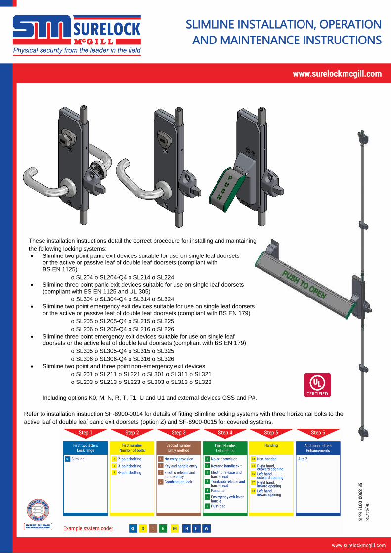
1. Ensure the door leaf is hung correctly and opens freely. Position the template accurately on door as indicated below, ensuring gridlines X and Y are in their correct positions. Note; this allows for 3mm (1/8”) bolt clearance from end of bolts to face of sockets when bolts are fully retracted. It is important to determine the final position of each socket face to enable correct positioning of the drilling template and cutting of top tube/ adjuster assembly.
2. Drill holes in door to suit chosen fixing method. Then fit the 2mm (1/16”) thick lock centre module packing plate to the door .
For timber doors, core fixings are recommended for maximum security and fire performance. For metal doors, machine screws going into an 8mm (5/16”) tapping plate within the leaf are recommended for maximum security and fire performance. Alternatively, machine screws going into steel clinch nuts may be used on metal fire doors, provided the clinch nut head projection is no greater than 0.38mm (0.015”).
Fixing pack code
Fixing method Drilling sizes
Centre module and bracket fixings
Handle hole*
* Only when external handle is required # For core fixings drill ½ way through only
Tighten fixings to a maximum torque of 15Nm (130lbf.in).
W Core fixings for timber doors 9mm# 15mm
W1 Coach bolts for timber or metal doors 9mm 15mm
W2 Coach screws for timber doors - 15mm
W3 Machine screws for metal doors M8 tapped 15mm
W10 Machine screws for metal doors 5/16”-18 UNC tapped 19/32”
2mm (1/16”) thick lock
centre module packing
plate or 5mm (13/64”) thick
load plate
Drill 16mm (5/8”)
diameter depth to
suit core fixings
Core fixings if
required
Centre of cylinder tail
Note: Refer to SF-8965 if
fitting Option D02
(25mm bolt ends)
125mm (4.921”)
36mm (1.417”)
2)
Gridline Y
2)
87.2mm (3.433”)
2) 87.2mm (3.433”)
2)
87.2mm (3.433”)
2)
87.2mm (3.433”)
2)
36mm (1.417”)
2)
Gridline X
2)
Gridline X
2)
Gridline Y
2)
36mm (1.417”)
2)
55mm (2 3/16”) to face of socket
55mm (2 3/16”) to face of socket
120mm (4 3/4") min
10
00
mm
(3
9 3
/8”)
to f
ace
of
so
cke
t
10
00
mm
(3
9 3
/8”)
to f
ace
of
so
cke
t
Place template on
door as shown
Single door
Double door
Active leaf Passive leaf
SLIMLINE INSTALLATION, OPERATION AND MAINTENANCE INSTRUCTIONS
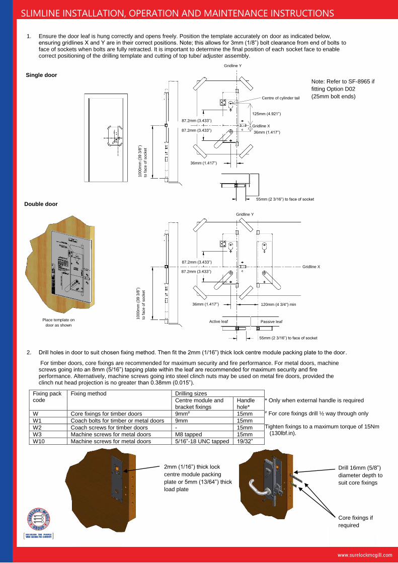
3. If required, fit the external cylinder / cylinder guard (options P, P3#, P4#, P5#, P6#) or LEO module (options L#) as directed in separate instructions supplied.
Fixing methods for installing GSS cylinder guards (options P3#, P4#, P5#, P6#) are shown below. Note, the position indicated on the paper template is the centre of the operating bar, not the centre of the cylinder body.
The operating bar will need to be cut to length to engage the lock by 4mm to 5mm (5/32” to 7/32”) (equal to projecting approximately 10mm (3/8”) from the face of the door leaf). For twin-lock systems two cylinder guards may be required.
Standard cylinder guard fixing method
Loadplate cylinder guard fixing method
Bolt-through cylinder guard fixing method
Cylinder tail to project
approximately 10mm
(3/8”) from the face of
the door leaf so it
engages 4mm to
5mm (5/32” to 7/32”)
into the lock
For timber doors use fixing plate
For steel doors omit fixing plate and prepare door as shown below
Steel door prep Timber door prep
Drill and countersink door as below Recess plate below into door
1 THRU HOLE Ø15 (5/8”)
6 HOLES 9.0 (0.354”)
CSK Ø17.0 (0.669”) x90°
ON PCD 48mm (1.89”)
1 HOLE OPPOSITE SIDE
Ø63.0 (2 1/2")
HOLE DEPTH = PANEL
THICKNESS - 6mm (1/4”)
1 HOLE M8 x 8mm
(5/16”-18 UNC x 5/16”)
31.8mm
(1.252”)
45° CENTRE OF
CYLINDER
6mm
(0.236”)
78.5mm (3.091”)
39.25mm (1.545”)
6mm
(0.236”)
6mm
(0.236”)
26.25mm
(1.033”)
67.5mm
(0.657”)
CENTRE OF
CYLINDER
6mm
(0.236”)
1 HOLE
Ø63.0 (2 1/2")
1 HOLE
Ø63.0 (2 1/2")
37.8mm
(1.488”)
CENTRE OF
CYLINDER
Ø12mm x 12mm DEEP
(Ø1/2” x 1/2" DEEP)
Ø12mm x 12mm DEEP
(Ø1/2” x 1/2" DEEP)
119mm
(4.685”)
25mm
(0.984”)
25mm
(0.984”)
87.2mm
(3.433”)
36mm
(1.417”) 3 HOLES
M8 (5/16”-18 UNC)
Gridline X
Gri
dlin
e Y

SLIMLINE INSTALLATION, OPERATION AND MAINTENANCE INSTRUCTIONS
4. Before fitting the centre module to the door, check alignment of the cylinder insert dot as shown below (not required if using a Europrofile cylinder).
If fitting a single action escape lever handle, go to Section 5,
If fitting an internal thumbturn or internal key (non-emergency escape), go to Section 8,
If fitting a panic bar or push pad, go to Section 10,
5. Single action escape lever handles
6. Fit the lock to the door using 2 off 8mm (5/18”-18 UNC) fixings and check the operation of the unit. Then fit the horizontal guide bracket (not applicable on two point systems). After fitting the bracket check the bolt has approximately 0.5mm (1/64”) clearance in all directions to ensure correct alignment of the bolt.
7. Fit the external lever handle if required, ensuring the spindle engages into the lock by 12mm (15/32”) (equal to projecting approximately 14.5mm (9/16”) from the face of the door leaf).
Go to Section 17.
On side(s) with cylinder or thumbturn
On the cylinder/thumbturn
side, the dot should be to
the top
Ensure the bolt has
approximately 0.5mm (1/64”)
clearance in all directions
For escape systems only
On sides with emergency escape lever
handle, push pad or panic bar
On the emergency escape
side, the dot should be to
the bottom. This is already
locked in place with an M3
screw
Ensure the spindle engages into the
lock by 12mm (15/32”) (equal to
projecting approximately 14.5mm
(9/16”) from the face of the door leaf)

SLIMLINE INSTALLATION, OPERATION AND MAINTENANCE INSTRUCTIONS
8. Internal thumbturns or internal keys
9. Assemble the thumbturn or internal key plate, handle and lock and fit to the door using two M8 (5/16”-18 UNC) fixings.
Cut the handle spindle to suit. Check the operation of the unit. Then fit the horizontal guide bracket (not applicable on two point systems). After fitting the bracket check the bolt has approximately 0.5mm (1/64”) clearance in all directions to ensure correct alignment of the bolt.
Go to Section 17.
Ensure the bolt has
approximately 0.5mm (1/64”)
clearance in all directions
SLIMLINE INSTALLATION, OPERATION AND MAINTENANCE INSTRUCTIONS
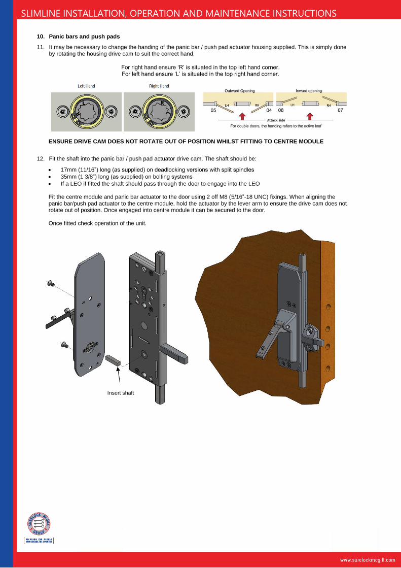
10. Panic bars and push pads
11. It may be necessary to change the handing of the panic bar / push pad actuator housing supplied. This is simply done by rotating the housing drive cam to suit the correct hand.
ENSURE DRIVE CAM DOES NOT ROTATE OUT OF POSITION WHILST FITTING TO CENTRE MODULE
12. Fit the shaft into the panic bar / push pad actuator drive cam. The shaft should be:
• 17mm (11/16”) long (as supplied) on deadlocking versions with split spindles
• 35mm (1 3/8”) long (as supplied) on bolting systems
• If a LEO if fitted the shaft should pass through the door to engage into the LEO Fit the centre module and panic bar actuator to the door using 2 off M8 (5/16”-18 UNC) fixings. When aligning the panic bar/push pad actuator to the centre module, hold the actuator by the lever arm to ensure the drive cam does not rotate out of position. Once engaged into centre module it can be secured to the door. Once fitted check operation of the unit.
For right hand ensure ‘R’ is situated in the top left hand corner. For left hand ensure ‘L’ is situated in the top right hand corner.
Insert shaft

SLIMLINE INSTALLATION, OPERATION AND MAINTENANCE INSTRUCTIONS
13. If fitting a panic bar, fit the pivot unit as shown.
Note the push bar may have to be cut to length. The push bar should be cut equally from both ends and must be at least 60% of the door width. It is recommended that the bar be as wide as possible to provide the maximum effective width.
14. Fit the push bar / push pad by sliding onto the nuts on the top of the lever arms, then tighten from the underside and fit the push bar end caps. Once fitted check operation.
15. Fit the horizontal bolt guide bracket (not applicable on two point systems). After fitting the bracket check the bolt has approximately 0.5mm (1/64”) clearance in all directions to ensure correct alignment of the bolt.
16. Fit the external lever handle if required, ensuring the spindle engages into the lock by 12mm (15/32”) (equal to projecting approximately 14.5mm (9/16”) from the face of the door leaf).
Ensure the spindle engages into the
lock by 12mm (15/32”) (equal to
projecting approximately 14.5mm
(9/16”) from the face of the door leaf)
810mm (2’ 8”) max
Push fit
end caps
Ensure the bolt has
approximately 0.5mm (1/64”)
clearance in all directions
SLIMLINE INSTALLATION, OPERATION AND MAINTENANCE INSTRUCTIONS
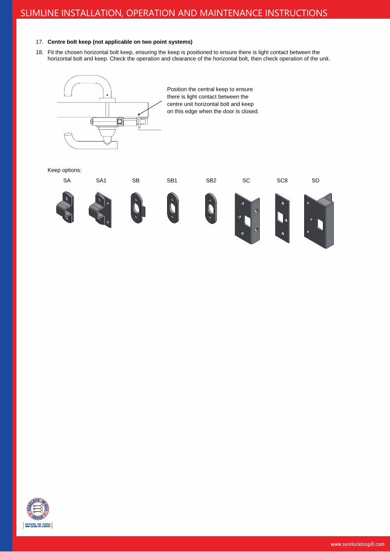
17. Centre bolt keep (not applicable on two point systems)
18. Fit the chosen horizontal bolt keep, ensuring the keep is positioned to ensure there is light contact between the horizontal bolt and keep. Check the operation and clearance of the horizontal bolt, then check operation of the unit.
Keep options:
SA SA1 SB SB1 SB2 SC SC8 SD
Position the central keep to ensure
there is light contact between the
centre unit horizontal bolt and keep
on this edge when the door is closed.
SLIMLINE INSTALLATION, OPERATION AND MAINTENANCE INSTRUCTIONS
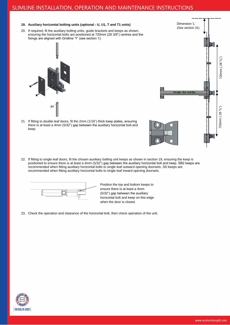
19. Auxiliary horizontal bolting units (optional - U, U1, T and T1 units)
20. If required, fit the auxiliary bolting units, guide brackets and keeps as shown, ensuring the horizontal bolts are positioned at 720mm (28 3/8”) centres and the fixings are aligned with Gridline ‘Y’ (see section 1).
21. If fitting to double leaf doors, fit the 2mm (1/16”) thick keep plates, ensuring there is at least a 4mm (5/32”) gap between the auxiliary horizontal bolt and keep.
22. If fitting to single leaf doors, fit the chosen auxiliary bolting unit keeps as shown in section 19, ensuring the keep is positioned to ensure there is at least a 4mm (5/32”) gap between the auxiliary horizontal bolt and keep. SB2 keeps are recommended when fitting auxiliary horizontal bolts to single leaf outward opening doorsets. SD keeps are recommended when fitting auxiliary horizontal bolts to single leaf inward opening doorsets.
23. Check the operation and clearance of the horizontal bolt, then check operation of the unit.
Position the top and bottom keeps to
ensure there is at least a 4mm
(5/32”) gap between the auxiliary
horizontal bolt and keep on this edge
when the door is closed.
Dimension ‘L’
(See section 31)
720m
m (
28 3
/ 8”)
720m
m (
28 3
/ 8”)
SLIMLINE INSTALLATION, OPERATION AND MAINTENANCE INSTRUCTIONS
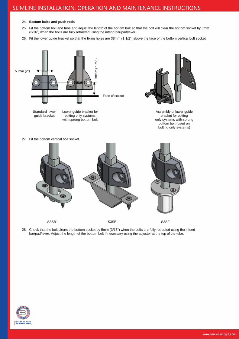
24. Bottom bolts and push rods
25. Fit the bottom bolt and tube and adjust the length of the bottom bolt so that the bolt will clear the bottom socket by 5mm (3/16”) when the bolts are fully retracted using the intend bar/pad/lever.
26. Fit the lower guide bracket so that the fixing holes are 38mm (1 1/2”) above the face of the bottom vertical bolt socket.
27. Fit the bottom vertical bolt socket.
S3SB1 S3SE S3SF
28. Check that the bolt clears the bottom socket by 5mm (3/16”) when the bolts are fully retracted using the intend bar/pad/lever. Adjust the length of the bottom bolt if necessary using the adjuster at the top of the tube.
Standard lower guide bracket
Lower guide bracket for bolting only systems
with sprung bottom bolt
Assembly of lower guide bracket for bolting
only systems with sprung bottom bolt (used on bolting only systems)
50mm (2”)
38m
m (
1 ½
”)
Face of socket
SLIMLINE INSTALLATION, OPERATION AND MAINTENANCE INSTRUCTIONS
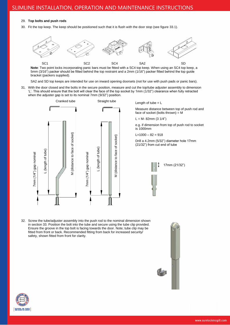
29. Top bolts and push rods
30. Fit the top keep. The keep should be positioned such that it is flush with the door stop (see figure 33.1).
SC1 SC2 SC4 SA2 SD
Note: Two point locks incorporating panic bars must be fitted with a SC4 top keep. When using an SC4 top keep, a 5mm (3/16”) packer should be fitted behind the top restraint and a 2mm (1/16”) packer fitted behind the top guide bracket (packers supplied).
SA2 and SD top keeps are intended for use on inward opening doorsets (not for use with push pads or panic bars).
31. With the door closed and the bolts in the secure position, measure and cut the top/tube adjuster assembly to dimension ‘L’. This should ensure that the bolt will clear the face of the top socket by 1mm (1/32”) clearance when fully retracted when the adjuster gap is set to its nominal 7mm (9/32”) position.
Cranked tube Straight tube
32. Screw the tube/adjuster assembly into the push rod to the nominal dimension shown
in section 33. Position the bolt into the tube and secure using the tube clip provided. Ensure the groove in the top bolt is facing towards the door. Note; tube clip may be fitted from front or back. Recommended fitting from back for increased security/ safety, shown fitted from front for clarity.
Length of tube = L
Measure distance between top of push rod and face of socket (bolts thrown) = M
L = M- 82mm (3 1/4”)
e.g. if dimension from top of push rod to socket is 1000mm
L=1000 – 82 = 918
Drill a 4.2mm (5/32”) diameter hole 17mm (21/32”) from cut end of tube
17mm (21/32”)
M (
dis
tan
ce
to
face
of socke
t)
M (
dis
tan
ce
to
face
of socke
t)
L (
len
gth
of
tube
)
L (
len
gth
of
tube
)
7m
m (
1/4
”) g
ap
no
min
al
7m
m (
1/4
”) g
ap
no
min
al

SLIMLINE INSTALLATION, OPERATION AND MAINTENANCE INSTRUCTIONS
33. Top Restraint for outward opening doors
Fit the top restraint assembly as shown in the following sub-sections.
33.1 Adjust the length of the top bolt/tube assembly to just clear the top socket when the system is fully retracted using the internal/external handle. Ensure that the groove in the bolt is facing toward the door.
33.2 Ensure the two spring arms point forward away from the face of the door as shown below.
If necessary push them over the central detent by inserting a tool from the opposite side (no dismantling is required).
33.3 Drill the two fixing holes in the door 38mm (1 1/2”) from the face of the keep, size to suit screws for chosen fixing method.
33.4 Remove the top shootbolt and fit the restraint/guide assembly to the door using two screws through the elongated slots. Ensure there is a 4mm (5/32”) gap between the top face of the restraint and the keep.
33.5 Refit the top shootbolt and check the roller clears the top keep by approximately 0.5mm (1/64”) when restrained. If necessary adjust the gap between the restraint and top keep.
33.6 If the central bolt hits the keep, increase the length of the top tube by rotating it in half turn increments until the bolts clear the keeps when the handle/pad/panic bar is depressed. If the bolts do not restrain when the when the handle/pad/panic bar is depressed reduce the length of the top tube or adjust the gap between the restraint and top keep.
33.7 Finally, adjust the strike screw to release the trigger from the bolt slot; this requires 2mm (1/16”) of slider movement only.
DO NOT OVER ADJUST AS THIS MAY CAUSE DAMAGE
.
When correctly positioned,
lock restraint in position by
inserting two screws at the
bottom of the restraint.
Bolt to just clear
the socket
when fully
retracted using
intend bar/
pad/lever
Ensure 4mm
(5/32”) gap Tip: use packers
to maintain the
gap while fitting
4mm (5/32”) to
face of socket
Restraint lock
screws. See
section 33.7.
Spring arms
38mm (1 1/2")
Roller to clear keep by
approx. 0.5mm (1/64”)
Strike
screw
Frame
Frame
Frame
Doo
r
Doo
r
Doo
r
SLIMLINE INSTALLATION, OPERATION AND MAINTENANCE INSTRUCTIONS
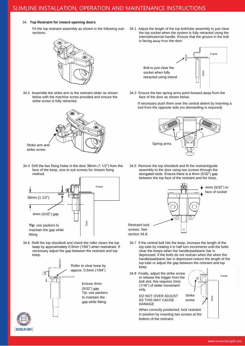
34. Top Restraint for inward opening doors
Fit the top restraint assembly as shown in the following sub-sections.
34.1 Adjust the length of the top bolt/tube assembly to just clear the top socket when the system is fully retracted using the internal/external handle. Ensure that the groove in the bolt is facing away from the door.
34.2 Assemble the strike arm to the restraint slider as shown below with the machine screw provided and ensure the strike screw is fully retracted.
34.3 Ensure the two spring arms point forward away from the face of the door as shown below.
If necessary push them over the central detent by inserting a tool from the opposite side (no dismantling is required).
34.4 Drill the two fixing holes in the door 38mm (1 1/2”) from the face of the keep, size to suit screws for chosen fixing method.
34.5 Remove the top shootbolt and fit the restraint/guide assembly to the door using two screws through the elongated slots. Ensure there is a 4mm (5/32”) gap between the top face of the restraint and the keep.
34.6 Refit the top shootbolt and check the roller clears the top keep by approximately 0.5mm (1/64”) when restrained. If necessary adjust the gap between the restraint and top keep.
34.7 If the central bolt hits the keep, increase the length of the top tube by rotating it in half turn increments until the bolts clear the keeps when the handle/pad/panic bar is depressed. If the bolts do not restrain when the when the handle/pad/panic bar is depressed reduce the length of the top tube or adjust the gap between the restraint and top keep.
34.8 Finally, adjust the strike screw to release the trigger from the bolt slot; this requires 2mm (1/16”) of slider movement only.
DO NOT OVER ADJUST AS THIS MAY CAUSE DAMAGE
Ensure 4mm
(5/32”) gap Tip: use packers
to maintain the
gap while fitting
Bolt to just clear the
socket when fully
retracted using intend
bar/ pad/lever
Strike arm and
strike screw
Spring arms
4mm (5/32”) gap
38mm (1 1/2")
Tip: use packers to
maintain the gap while
fitting
4mm (5/32”) to
face of socket
Restraint lock
screws. See
section 34.8.
Roller to clear keep by
approx. 0.5mm (1/64”)
When correctly positioned, lock restraint
in position by inserting two screws at the
bottom of the restraint.
Strike
screw
Frame
Frame
Frame
Doo
r
Doo
r
Doo
r
SLIMLINE INSTALLATION, OPERATION AND MAINTENANCE INSTRUCTIONS
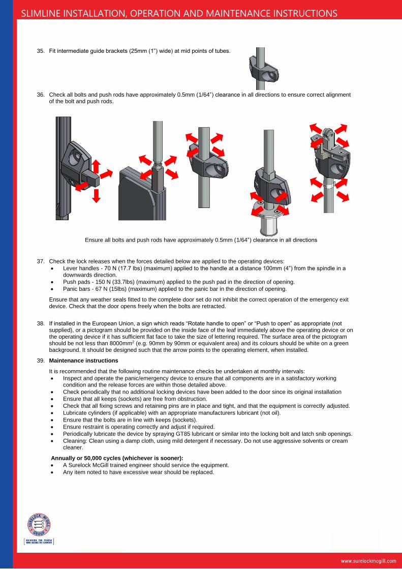
35. Fit intermediate guide brackets (25mm (1”) wide) at mid points of tubes.
36. Check all bolts and push rods have approximately 0.5mm (1/64”) clearance in all directions to ensure correct alignment of the bolt and push rods.
Ensure all bolts and push rods have approximately 0.5mm (1/64”) clearance in all directions
37. Check the lock releases when the forces detailed below are applied to the operating devices:
• Lever handles - 70 N (17.7 lbs) (maximum) applied to the handle at a distance 100mm (4”) from the spindle in a downwards direction.
• Push pads - 150 N (33.7lbs) (maximum) applied to the push pad in the direction of opening.
• Panic bars - 67 N (15lbs) (maximum) applied to the panic bar in the direction of opening.
Ensure that any weather seals fitted to the complete door set do not inhibit the correct operation of the emergency exit device. Check that the door opens freely when the bolts are retracted.
38. If installed in the European Union, a sign which reads “Rotate handle to open” or “Push to open” as appropriate (not
supplied), or a pictogram should be provided on the inside face of the leaf immediately above the operating device or on the operating device if it has sufficient flat face to take the size of lettering required. The surface area of the pictogram should be not less than 8000mm2 (e.g. 90mm by 90mm or equivalent area) and its colours should be white on a green background. It should be designed such that the arrow points to the operating element, when installed.
39. Maintenance instructions
It is recommended that the following routine maintenance checks be undertaken at monthly intervals:
• Inspect and operate the panic/emergency device to ensure that all components are in a satisfactory working condition and the release forces are within those detailed above.
• Check periodically that no additional locking devices have been added to the door since its original installation
• Ensure that all keeps (sockets) are free from obstruction.
• Check that all fixing screws and retaining pins are in place and tight, and that the equipment is correctly adjusted.
• Lubricate cylinders (if applicable) with an appropriate manufacturers lubricant (not oil).
• Ensure that the bolts are in line with keeps (sockets).
• Ensure restraint is operating correctly and adjust if required.
• Periodically lubricate the device by spraying GT85 lubricant or similar into the locking bolt and latch snib openings.
• Cleaning: Clean using a damp cloth, using mild detergent if necessary. Do not use aggressive solvents or cream cleaner.
Annually or 50,000 cycles (whichever is sooner):
• A Surelock McGill trained engineer should service the equipment.
• Any item noted to have excessive wear should be replaced.

SLIMLINE INSTALLATION, OPERATION AND MAINTENANCE INSTRUCTIONS
40. Operating instructions
1. Entry a. Release the deadlock (if applicable) using the key, electric release or combination lock (as applicable, see product codes on page 1). b. Whilst the deadlock is being held in the released position, fully depress the handle to retract the boltwork. c. Open the door.
2. Exit – Key, Electric Release or Turnknob a. Unlock the device using the key, electric release or turnknob (as applicable, see product codes on page 1). b. Whilst the deadlock is being held in the released position, fully depress the handle to retract the boltwork. c. Open the door.
3. Exit – Panic bar, Emergency Exit Lever Handle or Push pad a. Depress the panic bar/push pad or rotate the lever handle. b. Open the door.
4. Re-locking – The bolts relock and re-secure immediately upon door closure with the following exceptions:
Option A0 – Manual Bolting – Lift handle to reengage the bolts. Option K0 – Manual Deadlocking – Re-secure lock by rotating the key/turnknob to the locked position.
41. Wiring diagram
Request to Exit signalling
• Deadlock followed by REX = Entry from outside
• REX followed by Deadlock = Exit from inside
42. Solenoid power consumption
System Option code Voltage Power consumption per solenoid
Current draw per solenoid
Recommended power supply
Single solenoid
Twin solenoid
12V – Energise to unlock R (standard) 12V 10W 0.8A 12V 1.5A 12V 2A
24V – Energise to unlock R1 24V 10W 0.4A 24V 1.0A 24V 1.5A
12V – Energise to lock R2 12V 10W 0.8A 12V 1.5A 12V 2A
24V – Energise to lock R3 24V 10W 0.4A 24V 1.0A 24V 1.5A
1 - Black
2 - Yellow
3 - Red
4 - Green
5 - Blue
6 - White
7 - Violet
8 -.Brown
9 - Orange
10 - Pink
11 -Turquoise
12 - Grey
Solenoid
Deadlock status
Bolt status
Left hand locks = Bolt status
Right hand locks = Request to Exit (REX)
Left hand locks = Request to Exit (REX)
Right hand locks = Bolt status
Switches
shown with
lock secure
Preferred service partner
Web: www.247national.co.uk Tel: +44 (0) 8000 699 247