Embed Size (px)
Citation preview
SLN 700 SmartLine Non-Contact Radar Level Specification 34-SL-03-06, October 2020
Technical Information SmartLine
Introduction
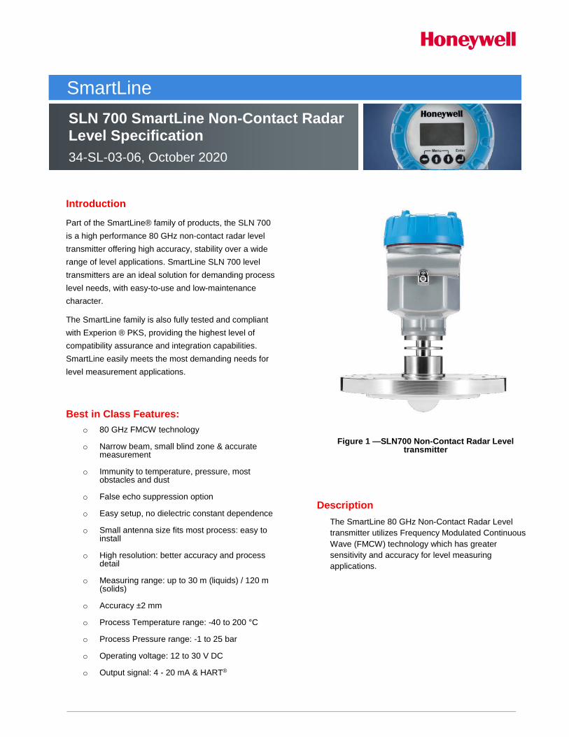
Part of the SmartLine® family of products, the SLN 700 is a high performance 80 GHz non-contact radar level transmitter offering high accuracy, stability over a wide range of level applications. SmartLine SLN 700 level transmitters are an ideal solution for demanding process level needs, with easy-to-use and low-maintenance character.
The SmartLine family is also fully tested and compliant with Experion ® PKS, providing the highest level of compatibility assurance and integration capabilities. SmartLine easily meets the most demanding needs for level measurement applications.
Best in Class Features: o 80 GHz FMCW technology
o Narrow beam, small blind zone & accurate
measurement
o Immunity to temperature, pressure, most obstacles and dust
o False echo suppression option
o Easy setup, no dielectric constant dependence
o Small antenna size fits most process: easy to install
o High resolution: better accuracy and process detail
o Measuring range: up to 30 m (liquids) / 120 m
(solids)
o Accuracy ±2 mm
o Process Temperature range: -40 to 200 °C
o Process Pressure range: -1 to 25 bar
o Operating voltage: 12 to 30 V DC
o Output signal: 4 - 20 mA & HART®
Figure 1 —SLN700 Non-Contact Radar Level
transmitter
Description The SmartLine 80 GHz Non-Contact Radar Level transmitter utilizes Frequency Modulated Continuous Wave (FMCW) technology which has greater sensitivity and accuracy for level measuring applications.
2 SmartLine Level Transmitter
Unique Out-of-the-Box, Full User Experience1 The specification of the correct level transmitter for the level measurement is one of the root causes for many common field failure modes. This user experience is enhanced with the unique SmartLine Application and Validation Tool (AVT) found at https://config.honeywellsmartline.com/. This allows users to specify their tank level application and the options desired for their level transmitter. The AVT intelligently guides the user through the engineering process and electronically captures and documents the choices and inputs. In addition to serving as engineering documentation, the AVT output also serves as input to the Honeywell order management system, thus ensuring correct input of the transmitter model. The additional advantage is a transmitter with configuration parameters already specified to match the targeted tank application. Errors are eliminated and the engineering effort is preserved from start to finish. The SmartLine Application and Validation Tool also allows users to collaboratively use and share the active session with any web connected colleague or expert. This interactive, collaborative capability eliminates roadblocks and delays. Users can access resources to help start and finish the engineering task in a single effort. This online tool also dynamically reformats the user interface to display correctly on an IOS or AndroidTM device. 1 will be available soon. Diagnostics SmartLine transmitters all offer digitally accessible diagnostics which aid in providing advanced warning of possible failure events, minimizing unplanned shutdowns, providing lower overall operational costs System Integration o SmartLine communications protocols all meet the
most current published standards for HART® o Integration with Honeywell’s Experion® PKS offers
the following unique advantages. • FDM Plant Area Views with Health
summaries • The SLN series is Experion tested to provide
the highest level of compatibility assurance. o Display modular can be added or removed in the
field o 128 by 64 dot matrix graphics display o Large PV font format supported. Echo stem plots
with Distance to Product and Distance to Interface Configurable screen
o The Display supports English and Chinese languages.
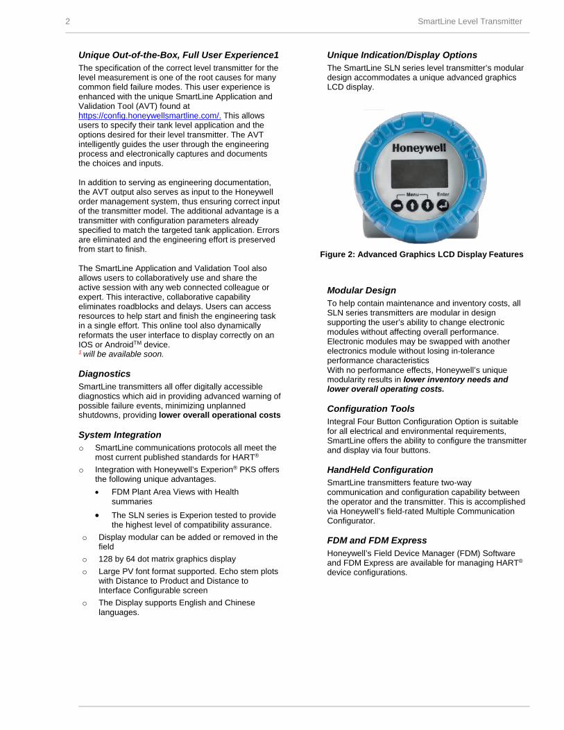
Unique Indication/Display Options The SmartLine SLN series level transmitter’s modular design accommodates a unique advanced graphics LCD display.
Figure 2: Advanced Graphics LCD Display Features
Modular Design To help contain maintenance and inventory costs, all SLN series transmitters are modular in design supporting the user’s ability to change electronic modules without affecting overall performance. Electronic modules may be swapped with another electronics module without losing in-tolerance performance characteristics With no performance effects, Honeywell’s unique modularity results in lower inventory needs and lower overall operating costs. Configuration Tools Integral Four Button Configuration Option is suitable for all electrical and environmental requirements, SmartLine offers the ability to configure the transmitter and display via four buttons. HandHeld Configuration SmartLine transmitters feature two-way communication and configuration capability between the operator and the transmitter. This is accomplished via Honeywell’s field-rated Multiple Communication Configurator. FDM and FDM Express Honeywell’s Field Device Manager (FDM) Software and FDM Express are available for managing HART®
device configurations.
SmartLine Level Transmitter 3
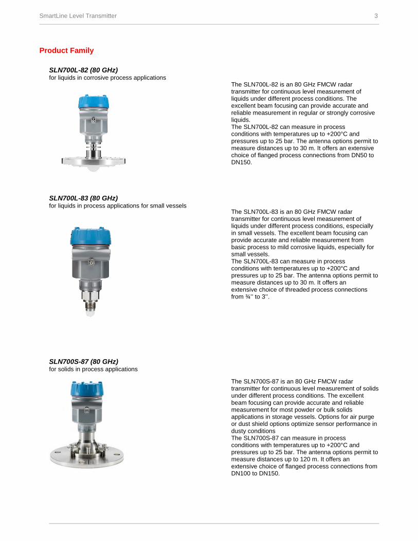
Product Family SLN700L-82 (80 GHz) for liquids in corrosive process applications SLN700L-83 (80 GHz) for liquids in process applications for small vessels SLN700S-87 (80 GHz) for solids in process applications
The SLN700L-82 is an 80 GHz FMCW radar transmitter for continuous level measurement of liquids under different process conditions. The excellent beam focusing can provide accurate and reliable measurement in regular or strongly corrosive liquids. The SLN700L-82 can measure in process conditions with temperatures up to +200°C and pressures up to 25 bar. The antenna options permit to measure distances up to 30 m. It offers an extensive choice of flanged process connections from DN50 to DN150. The SLN700L-83 is an 80 GHz FMCW radar transmitter for continuous level measurement of liquids under different process conditions, especially in small vessels. The excellent beam focusing can provide accurate and reliable measurement from basic process to mild corrosive liquids, especially for small vessels. The SLN700L-83 can measure in process conditions with temperatures up to +200°C and pressures up to 25 bar. The antenna options permit to measure distances up to 30 m. It offers an extensive choice of threaded process connections from ¾’’ to 3’’. The SLN700S-87 is an 80 GHz FMCW radar transmitter for continuous level measurement of solids under different process conditions. The excellent beam focusing can provide accurate and reliable measurement for most powder or bulk solids applications in storage vessels. Options for air purge or dust shield options optimize sensor performance in dusty conditions The SLN700S-87 can measure in process conditions with temperatures up to +200°C and pressures up to 25 bar. The antenna options permit to measure distances up to 120 m. It offers an extensive choice of flanged process connections from DN100 to DN150.
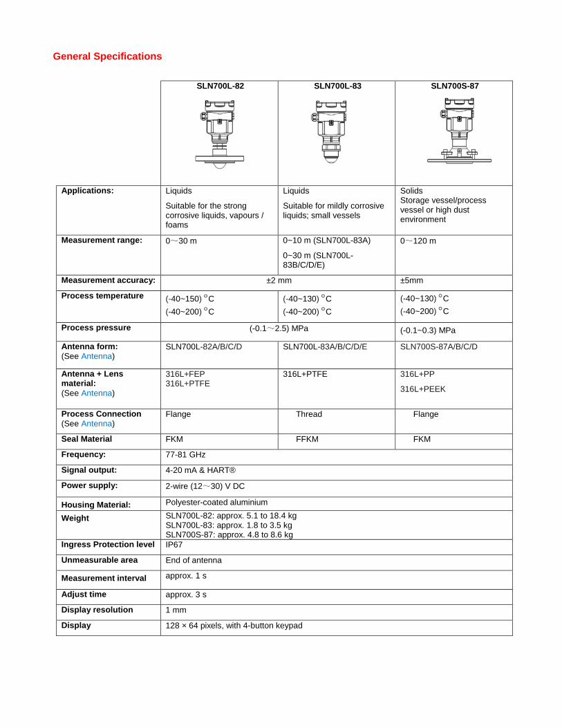
General Specifications
SLN700L-82
SLN700L-83
SLN700S-87
Applications: Liquids
Suitable for the strong corrosive liquids, vapours / foams
Liquids
Suitable for mildly corrosive liquids; small vessels
Solids Storage vessel/process vessel or high dust environment
Measurement range: 0~30 m 0~10 m (SLN700L-83A)
0~30 m (SLN700L-83B/C/D/E)
0~120 m
Measurement accuracy: ±2 mm ±5mm
Process temperature (-40~150) °C (-40~200) °C
(-40~130) °C (-40~200) °C
(-40~130) °C (-40~200) °C
Process pressure (-0.1~2.5) MPa (-0.1~0.3) MPa
Antenna form: (See Antenna)
SLN700L-82A/B/C/D SLN700L-83A/B/C/D/E SLN700S-87A/B/C/D
Antenna + Lens material: (See Antenna)
316L+FEP 316L+PTFE
316L+PTFE 316L+PP
316L+PEEK
Process Connection (See Antenna)
Flange Thread Flange
Seal Material FKM FFKM FKM
Frequency: 77-81 GHz
Signal output: 4-20 mA & HART®
Power supply: 2-wire (12~30) V DC
Housing Material: Polyester-coated aluminium
Weight SLN700L-82: approx. 5.1 to 18.4 kg SLN700L-83: approx. 1.8 to 3.5 kg SLN700S-87: approx. 4.8 to 8.6 kg
Ingress Protection level IP67
Unmeasurable area End of antenna
Measurement interval approx. 1 s
Adjust time approx. 3 s
Display resolution 1 mm
Display 128 × 64 pixels, with 4-button keypad

Operating Conditions – All Models Parameter Description Environmental Operating temperature1
Device Operating range: -25 to 80°C
Display operating range: -20 to 80°C Temperature for storage and transport
-40 to +80 °C
Relative humidity <95% Power Supply 2-wire
Standard type (12~30) V DC Intrinsically safe (12~30) V DC Power consumption max.22.5 mA Ripples are allowed -<100Hz -(100~100K)Hz
Uss<1 V Uss<10 mV
Cable parameters Cable entry/plug M20x1.5/ ½’NPT cable entry, and M20x1.5/ ½’NPT blind plug
Spring collecting terminals Used for conductor with cross section of 2.5 mm2
Output parameter Output signal (4-20) mA/HART®
Resolution 0.3 μA -2-wire load resistance Refer to Figure 3
1 The ambient temperature limit for intrinsic safety differs. See section on Hazardous Locaiton Approvals.
2-wire load resistance Maximum Loop Resistance (Ω)
Figure 3: 2-wire load resistance
Supply Voltage Max. Loop (VDC) Resistance (Ω)
12 0 17.5 250 23 500 30 818
Supply Voltage(VDC)
Note: A minimum of 250 Ω of loop resistance is required to support communications. Loop resistance = Barrier resistance + Wire resistance + Receiver resistance
Performance Under Rated Conditions – All Models Parameter Description Analog Output Digital Communications:
Two-wire, 4 to 20 mA HART® 7 protocol
Output Failure Modes Compliance: Honeywell Standard: Normal Limits: 3.8 – 20.8 mA Failure Mode: ≤ 3.6 mA and ≥ 21.0 mA
Measurement accuracy Refer to figure on page 7 Temperature drift ±2 mm/10 K Repeatability ±1 mm Dielectric constant (minimum) 1.4 Electromagnetic Compatibility and Radio Equipment
EN 301 489-1 V2.2.0, EN 301 489-3 V2.1.1, EN 302 729 V2.1.1, EN 302 372 V2.1.1, EN 62311:2008
Electrical Safety EN 61010-1:2010 Vibration-proof Mechanical shock 10 m/s2, 10-150 Hz
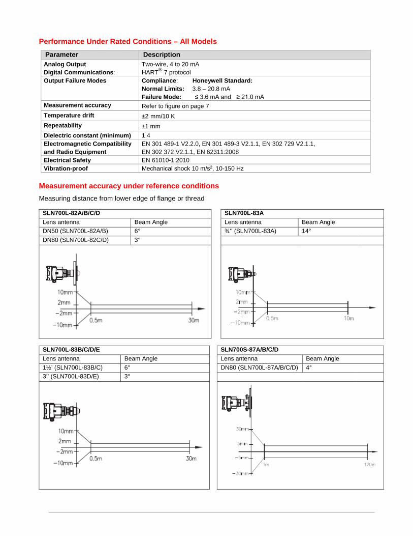
Measurement accuracy under reference conditions Measuring distance from lower edge of flange or thread
SLN700L-82A/B/C/D SLN700L-83A Lens antenna Beam Angle Lens antenna Beam Angle DN50 (SLN700L-82A/B) 6° ¾’’ (SLN700L-83A) 14° DN80 (SLN700L-82C/D) 3°
SLN700L-83B/C/D/E SLN700S-87A/B/C/D Lens antenna Beam Angle Lens antenna Beam Angle 1½’ (SLN700L-83B/C) 6° DN80 (SLN700L-87A/B/C/D) 4° 3’’ (SLN700L-83D/E) 3°

Antenna
No. SLN700L-82A SLN700L-82B SLN700L-82C SLN700L-82D
Material 316L+FEP 316L+PTFE
316L+FEP 316L+PTFE
316L+FEP 316L+PTFE
316L+FEP 316L+PTFE
Process Connection DN50
DN80 DN100
DN50 DN80 DN100 DN150
DN80 DN100 DN125 DN150
DN80 DN100 DN125
Features Anti-corrosion High Pressure Single radiator 150 ℃
Anti-corrosion High Pressure Multi-fin radiator 200 ℃
Anti-corrosion High Pressure Single radiator 150℃
Anti-corrosion High Pressure Multi-fin radiator 200 ℃
No. SLN700L-83A SLN700L-83B SLN700L-83C SLN700L-83D SLN700L-83E Material 316L+PTFE 316L+PTFE 316L+PTFE 316L+PTFE 316L+PTFE
Process Connection
Thread G¾ A Thread ¾ NPT
Thread G1½ A Thread 1½ NPT
Thread G1½ A Thread 1½ NPT
Thread G3 A Thread G3 A
Features Anti-corrosion Anti-corrosion Anti-corrosion Anti-corrosion Anti-corrosion
No. SLN700S-87A SLN700S-87B SLN700S-87C SLN700S-87D Material 316L+PP/
316L+PEEK 316L+PEEK
316L+PP/ 316L+PEEK
316L+PEEK
Process Connection
DN100 DN125 DN150
DN100 DN125 DN150
DN100 DN125 DN150
DN100 DN125 DN150
Features Thread/purging Micro Pressure 130 ℃
Thread/purging Micro Pressure with Radiator 200 ℃
Universal/purging Atmospheric 130 ℃
Universal/purging Atmospheric with Radiator 200 ℃
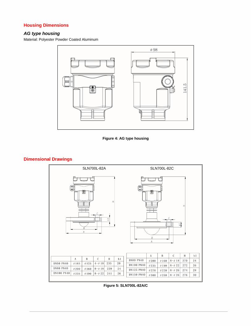
Housing Dimensions AG type housing Material: Polyester Powder Coated Aluminum
Figure 4: AG type housing
Dimensional Drawings
Figure 5: SLN700L-82A/C
SLN700L-82A SLN700L-82C

Figure 6: SLN700L-82B/D
Figure 7: SLN700L-83A/B/C
SLN700L-82B SLN700L-82D
SLN700L-83A SLN700L-83B SLN700L-83C
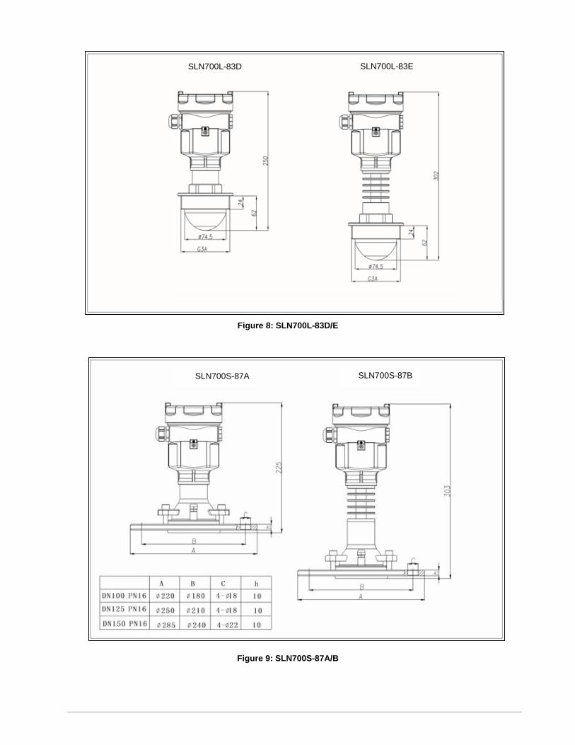
Figure 8: SLN700L-83D/E
Figure 9: SLN700S-87A/B
SLN700S-87A SLN700S-87B
SLN700L-83D SLN700L-83E
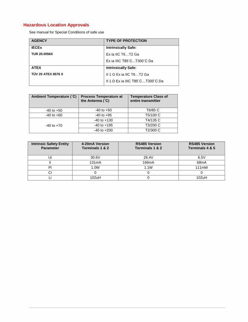
Hazardous Location Approvals See manual for Special Conditions of safe use
AGENCY TYPE OF PROTECTION
IECEx TUR 20.0056X
Intrinsically Safe:
Ex ia IIC T6…T2 Ga
Ex ia IIIC T85˚C...T300˚C Da
ATEX TÜV 20 ATEX 8576 X
Intrinsically Safe:
II 1 G Ex ia IIC T6…T2 Ga
II 1 D Ex ia IIIC T85˚C…T300˚C Da
Ambient Temperature (˚C) Process Temperature at the Antenna (˚C)
Temperature Class of entire transmitter
-40 to +50 -40 to +50 T6/85 C -40 to +60 -40 to +95 T5/100 C
-40 to +70 -40 to +130 T4/135 C -40 to +195 T3/200 C -40 to +200 T2/300 C
Intrinsic Safety Entity Parameter
4-20mA Version Terminals 1 & 2
RS485 Version Terminals 1 & 2
RS485 Version Terminals 4 & 5
Ui 30.6V 26.4V 6.5V Ii 131mA 166mA 68mA Pi 1.0W 1.1W 111mW Ci 0 0 0 Li 102uH 0 102uH
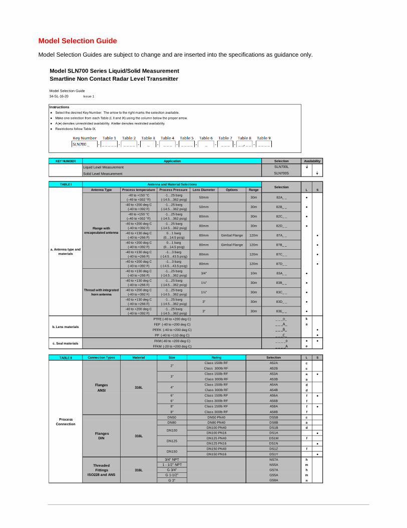
Model Selection Guide
Model Selection Guides are subject to change and are inserted into the specifications as guidance only.
Model SLN700 Series Liquid/Solid MeasurementSmartline Non Contact Radar Level Transmitter
Model Selection Guide34-SL-16-20 Issue 1
Instructions ● Select the desired Key Number. The arrow to the right marks the selection available. ● Make one selection from each Table (I, II and IX) using the column below the proper arrow. ● A (●) denotes unrestricted availability. A letter denotes restricted availability. ● Restrictions follow Table IX.
KEY NUMBER
TABLE IL S
●
●
●
●
●
●
●
●
●
●
●
●
●
ka
●●
● ●e
TABLE II L S
cca ●addf ●ff ●fcad
●f
●f
●hmhmn
c. Seal materials
FlangesANSI
Application Selection Availability
SelectionProcess temperature Process Pressure Lens Diameter
-40 to +150 °C(–40 to +302 °F)
-1…25 barg (-14.5…362 psig) 50mm
-40 to +150 °C(–40 to +302 °F)
-1…25 barg (-14.5…362 psig)
82D_ _
82A_ _
-40 to +200 deg C (-40 to +392 F)
-1…25 barg (-14.5…362 psig)
82C_ _
-40 to +200 deg C (-40 to +392 F)
-1…25 barg (-14.5…362 psig) 80mm
-40 to +130 deg C (-40 to +266 F)
-1…3 barg (-14.5…43.5 psig) 80mm
120m
120m
80mm 87A_ _
-40 to +200 deg C (-40 to +392 F)
0…1 barg (0…14.5 psig) 80mm 87B_ _
80mm
87C_ _
b. Lens materials
_ _ _0_
Thread with integrated horn antenna
-40 to +130 deg C (-40 to +266 F)
-1…25 barg (-14.5…362 psig) 3/4'' 83A_ _
-40 to +130 deg C (-40 to +266 F)
-1…25 barg (-14.5…362 psig) 1½''
-40 to +130 deg C (-40 to +266 F)
-1…25 barg (-14.5…362 psig) 3'' 83D_ _
-40 to +200 deg C (-40 to +392 F)
-1…25 barg (-14.5…362 psig)
a. Antenna type and materials
Antenna Type
30m
30m
82B_ _
30m
30m
Flange with encapsulated antenna
Connection Types Material Size Rating Selection
_ _ _A_ _ _ _B_ _ _ _C_
FEP (-40 to +200 deg C)PEEK (-40 to +200 deg C)
PP (-40 to +110 deg C)
_ _ _ _0_ _ _ _A
FKM (-40 to +200 deg C)FFKM (-20 to +200 deg C)
Process Connection
2"Class 150lb RF AS2AClass 300lb RF AS2B
3"Class 150lb RF AS3AClass 300lb RF AS3B
6" Class 150lb RF AS6AClass 300lb RF AS6B
Class 300lb RF AS8B
4"Class 150lb RF AS4AClass 300lb RF AS4B
8" Class 150lb RF AS8A
FlangesDIN 316L
DN50 DN50 PN40 DS5BDN80 DN80 PN40 DS8B
DN100DN100 PN40
DN150DN150 PN40 DS1ZDN150 PN16 DS1Y
DS1BDN100 PN16 DS1A
DN125DN125 PN40 DS1MDN125 PN16 DS1N
ThreadedFittings
ISO228 and ANS316L
3/4" NPT NS7A1 - 1/2" NPT NS5A
G 3/4" GS7AG 1-1/2" GS5A
G 3" GS8A
Options
Gimbal Flange
Gimbal Flange
316L
6"
8"
10m
120m
PTFE (-40 to +200 deg C)
83E_ _
83B_ _
-40 to +200 deg C (-40 to +392 F)
-1…25 barg (-14.5…362 psig) 1½'' 83C_ _
30m
30m
3''
0…1 barg (0…14.5 psig)
120m 87D_ _
-40 to +130 deg C (-40 to +266 F)
Antenna and Material Selections
Liquid Level Measurement SLN700L
Solid Level Measurement SLN700S
50mm
-40 to +200 deg C (-40 to +392 F)
-1…3 barg (-14.5…43.5 psig) 80mm
Range
30m
30m
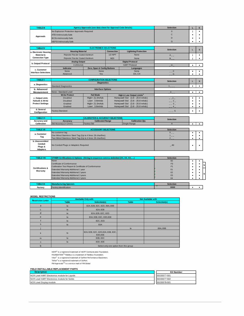
TABLE III L Sj ●● ●● ●● ●
TABLE IV
j ●j ●
● ●
● ●● ●
TABLE V
● ●
● ●
● ●● ●● ●● ●
d. General Configuration ● ●
TABLE VI
● ●
TABLE VII● ●● ●● ●
b. Unassembled Conduit Plugs &
Adapters
● ●
TABLE VIII● ●● ●● ●● ●● ●● ●● ●
TABLE IXFactory ● ●
MODEL RESTRICTIONS
ac defh
j
k
m
n
b
HART® is a registered trademark of HART Communication Foundation.FOUNDATIONTM Fieldbus is a trademark of Fieldbus Foundation.Viton® is a registered trademark of DuPont Performance Elastomers.Teflon® is a registered trademark of DuPont.FM ApprovalsSM is a service mark of FM Global
FIELD INSTALLABLE REPLACEMENT PARTSDescription
b. Advanced Measurement
c. Output Limit, Failsafe & Write Protect Settings
Accuracy and Calibration
Approvals
a. Electronic Housing Material &
Connection Type
b. Output/ Protocol
c. Customer Interface Selections
a. DiagnosticsS
DiagnosticsStandard Diagnostics 1 _ _ _
CONFIGURATION SELECTIONS Selection L
_ _1 _
Interface OptionsNone - Standard Level _ 0 _ _
Write Protect Fail Mode High & Low Output Limits3
Disabled High> 21.0mAdc Honeywell Std (3.8 - 20.8 mAdc)Disabled Low< 3.6mAdc Honeywell Std (3.8 - 20.8 mAdc) _ _ 2 _Enabled High> 21.0mAdc Honeywell Std (3.8 - 20.8 mAdc) _ _ 3 _Enabled Low< 3.6mAdc Honeywell Std (3.8 - 20.8 mAdc) _ _ 4 _
Factory Standard _ _ _ S
CALIBRATION & ACCURACY SELECTIONS Selection
ACCESSORY SELECTIONS Selection
a. Customer Tag
No customer tag 0 _ _One Wired Stainless Steel Tag (Up to 4 lines 26 char/line) 1 _ _Two Wired Stainless Steel Tag (Up to 4 lines 26 char/line) 2 _ _
Accuracy Calibrated RangeStd Accuracy (+/-2mm) Factory Std Single Range A
Calibration Qty
Calibration Test Report & Certificate of Conformance F1
No Conduit Plugs or Adapters Required _ A0
F3
Restriction Letter Available Only with Not Available withTable Selection(s) Table Selection(s)
OTHER Certifications & Options: (String in sequence comma delimited (XX, XX, XX,….) SelectionNone 00
Manufacturing Specials Selection0000Factory Identification
bExtended Warranty Additional 2 years 02Extended Warranty Additional 3 years 03Extended Warranty Additional 4 years 04
Certifications & Warranty Extended Warranty Additional 1 year 01
bCertificate of Conformance
Ia 82A, 82B, 82C, 82D
Ia 82A, 82B, 82C, 82D, 89A, 89B
Ia 82A, 82B
Kit Number50155577-501
Agency Approvals (see data sheet for Approval Code Details) Selection
D
Ia 89A, 89B
Ia 82A, 82B, 82C, 82D,83A, 83B, 83C, 83D,83E
Ia 83B, 83C
No Explosion Protection Approvals Required 0ATEX Intrinsically Safe C
IECEx Intrinsically SafeNEPSI Intrinsically Safe G
ELECTRONICS SELECTIONSSelection L
Housing Material Connection Lightning ProtectionPolyester Pow der Coated Aluminum 1/2 NPT None A _ _Polyester Pow der Coated Aluminum M20 None B _ _
_ H _Analog Output Digital Protocol
4-20mA dc HART ProtocolLanguages
None None NoneIndicator Zero, Span & Config Buttons
S
Ia 83A, 83B, 83C, 83D,83E
Advanced Yes EN, CH _ _ G_ _ 0
50155577-502NCR Level HART Electronics module for LiquidsNCR Level HART Electronics module for SolidsNCR Level Display module 50155578-501
Select only one option from this group
Ia 83D, 83E
83A
Ia 82C, 82D
Ia
For more information To learn more about SmartLine Transmitters, visit www.honeywellprocess.com Or contact your Honeywell Account Manager
Process Solutions Honeywell
1250 W Sam Houston Pkwy S Houston, USA, TX 77042
Honeywell Control Systems Ltd Honeywell House, Skimped Hill Lane Bracknell, England, RG12 1EB
34-SL-03-06 October 2020 2020 Honeywell International Inc.
Shanghai City Centre, 100 Jungi Road Shanghai, China 20061 www.honeywellprocess.com
Sales and Service For application assistance, current specifications, ordering, pricing, and name of the nearest Authorized Distributor, contact one of the offices below.
ASIA PACIFIC Honeywell Process Solutions, Phone: + 800 12026455 or +44 (0) 1202645583 (TAC) [email protected] Australia Honeywell Limited Phone: +(61) 7-3846 1255 FAX: +(61) 7-3840 6481 Toll Free 1300-36-39-36 Toll Free Fax: 1300-36-04-70 China – PRC - Shanghai Honeywell China Inc. Phone: (86-21) 5257-4568 Fax: (86-21) 6237-2826 Singapore Honeywell Pte Ltd. Phone: +(65) 6580 3278 Fax: +(65) 6445-3033 South Korea Honeywell Korea Co Ltd Phone: +(822) 799 6114 Fax: +(822) 792 9015
EMEA Honeywell Process Solutions, Phone: + 800 12026455 or +44 (0) 1202645583 Email: (Sales) [email protected] or (TAC) [email protected]
Web Knowledge Base search engine http://bit.ly/2N5Vldi
AMERICAS Honeywell Process Solutions, Phone: (TAC) (800) 423-9883 or (215) 641-3610 (Sales) 1-800-343-0228 Email: (Sales) [email protected] or (TAC) [email protected] Web Knowledge Base search engine http://bit.ly/2N5Vldi
Specifications are subject to change without notice.