Embed Size (px)
Citation preview

SlN,G,ER' BU$IN.ESS MACHIN.ES '
Copyright © 1972, The Singer Company All rights reserved throughout the world.
SYSTEM SUMMARY MANUAL
Publication No. 40-329 April 1972
SINGER BUSINESS MACHINES
2350 WASHINGTON AVE
SAN LEANDRO. CALIF. 94577
PRINTED IN U.S.A.
4/72
Page
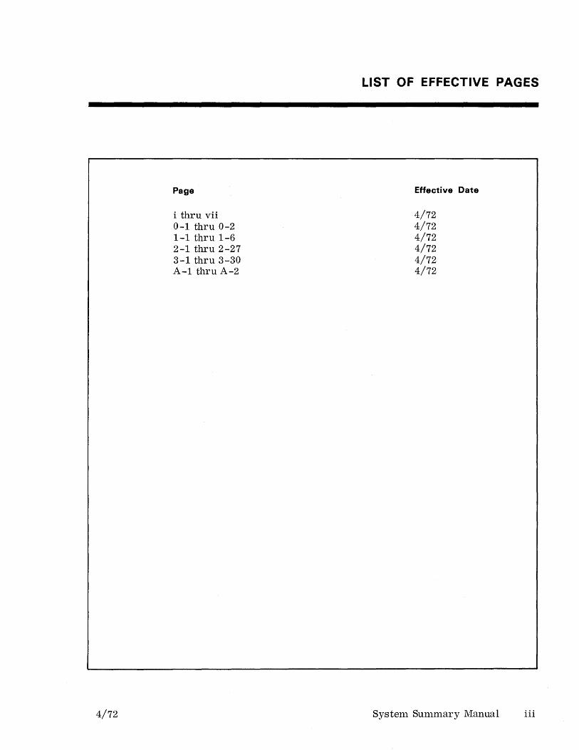
i thru vii 0-1 thru 0-2 1-1 thru 1-6 2-1 thru 2-27 3-1 thru 3-30 A-1 thru A-2
LIST OF EFFECTIVE PAGES
Effective Date
4/72 4/72 4/72 4/72 4/72 4/72
System Summary Manual iii
1
2
4/72
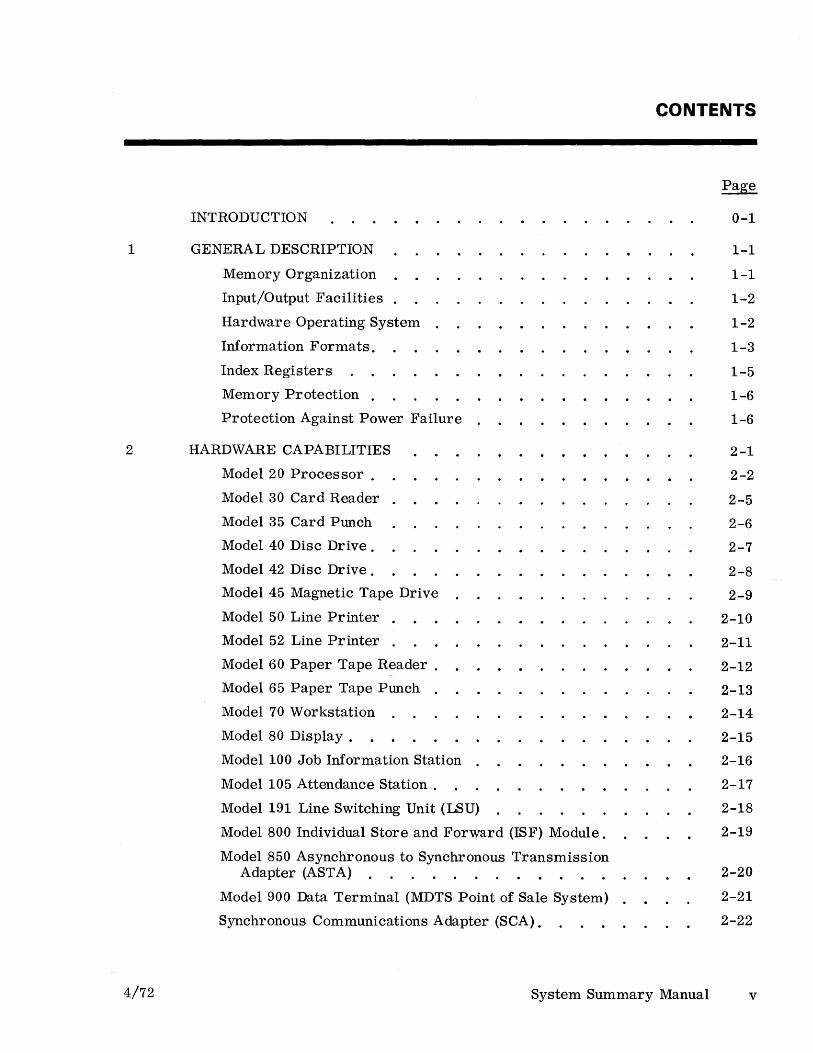
INTRODUCTION
GENERAL DESCRIPTION
Memory Organization
Input/Output Facilities .
Hardware Operating System .
Information Formats.
Index Register s
Memory Protection .
Protection Against Power Failure .
HARDWARE CAPABILITIES
Model 20 Processor.
Model 30 Card Reader .
Model 35 Card Punch
Model 40 Disc Drive.
Model 42 Disc Drive.
Model 45 Magnetic Tape Drive
Model 50 Line Printer .
Model 52 Line Printer .
Model 60 Paper Tape Reader.
Model 65 Paper Tape Punch .
Model 70 Workstation
Model 80 Display.
Model 100 Job Information Station
Model 105 Attendance Station.
Model 191 Line Switching Unit (LSU)
Model 800 Individual Store and Forward (!SF) Module.
Model 850 Asynchronous to Synchronous Transmission Adapter (ASTA)
Model 900 Data Terminal (MDTS Point of Sale System) .
Synchronous Communications Adapter (SCA).
CONTENTS
0-1
1-1
1-1
1-2
1-2
1-3
1-5
1-6
1-6
2-1
2-2
2-5
2-6
2-7
2-8
2-9
2-10
2-11
2-12
2-13
2-14
2-15
2-16
2-17
2-18
2-19
2-20
2-21
2-22
System Summary Manual v
Contents
3
Asynchronous Communications Adapter (ACA) .
Asynchronous Terminal Adapter (ATA)
Modular Data Systems (MDS) Input/Output Channel
Digital Clock Input/Output Channel .
External Clock Interface (ECI)
SOFTWARE CAPABILITIES
Disc Management Facility (DMF)
Assembler II .
Report Program Generator - RPG09
Report Program Generator - RPG10
APPEND (DMF) .
Conversational Testing Program-TESTER
DMF Disc Sort
DMF File Copy
DMF Multi-Partition Loader (DMF MPL).
Language Editor Utility (LEU)
Text Editor.
Compatible Programs .
Assembler I
Absolute Object Card Loader.
Branch Trace .
Code Translation (COTRAN) .
Conversational Testing Program - EZTEST .
Disc Sort
File Copy .
Interpretive Dump
Multi-Partition Loader (MPL)
Stand-Alone Dump
Remote Job Facility (RJF).
Remote Job Facility (RJF) - Disc Version
Synchronous Communication Access Method (SCAM) .
Modular Business Management System (MBMS).
vi System Summary Manual
Page
2-23
2-24
2-25
2-26
2-27
3-1
3-2
3-5
3-6
3-7
3-8
3-9
3-10
3-11
3-12
3-13
3-14
3-16
3-17
3-18
3-19
3-20
3-21
3-22
3-23
3-24
3-25
3-26
3-27
3-28
3-29
3-30
4/72

Contents
APPENDIX A: REFERENCE DOCUMENTS.
Page
A-I
ILL USTRATIONS
Figures
1-1
1-2
1-3
TABLES
3-1
4/72
Title
Model 20 Processor, Expanded
ASCII Chart .
IOC Input Conversion .
0-2
1-4
1-4
Total Core Used by Partition LIOeS . 3-4
System Summary Manual vii
INTRODUCTION
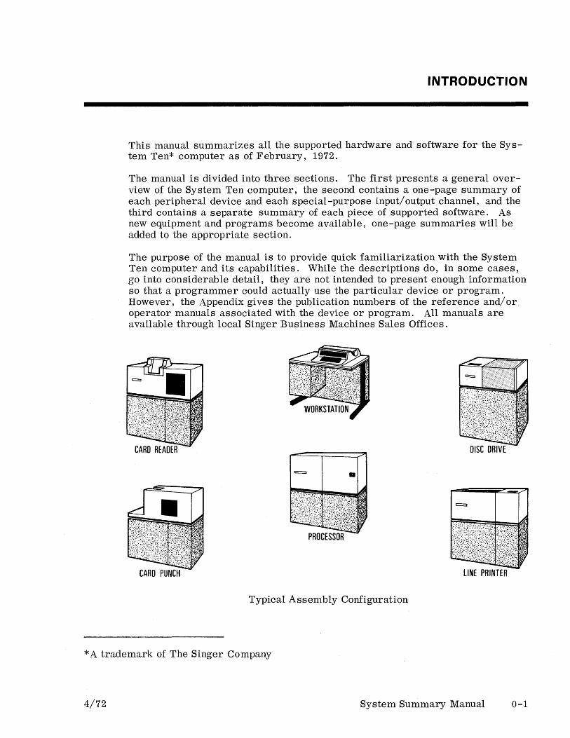
This manual summarizes all the supported hardware and software for the System Ten* computer as of February, 1972.
The manual is divided into three sections. The first presents a general overview of the System Ten computer, the second contains a one-page summary of each peripheral device and each special-purpose input/output channel, and the third contains a separate summary of each piece of supported software. As new equipment and programs become available, one-page summaries will be added to the appropriate section.
The purpose of the manual is to provide quick familiarization with the System Ten computer and its capabilities. While the descriptions do, in some cases, go into considerable detail, they are not intended to present enough information so that a programmer could actually use the particular device or program. However, the Appendix gives the publication numbers of the reference and/or operator manuals associated with the device or program. All manuals are available through local Singer Business Machines Sales Offices.
== a
PROCESSOR
CARD PUNCH LINE PRINTER
Typical Assembly Configuration
* A trademark of The Singer Company
4/72 System Summary Manual 0-1
General Description
TO PERIPHERALS
I I I I I I
..J
PARTITION 0
PARTITION 1
PARTITION 2
PARTITION 3
PARTITION 19
DISC CONTROLLER
MAG TAPE CONTROLLER
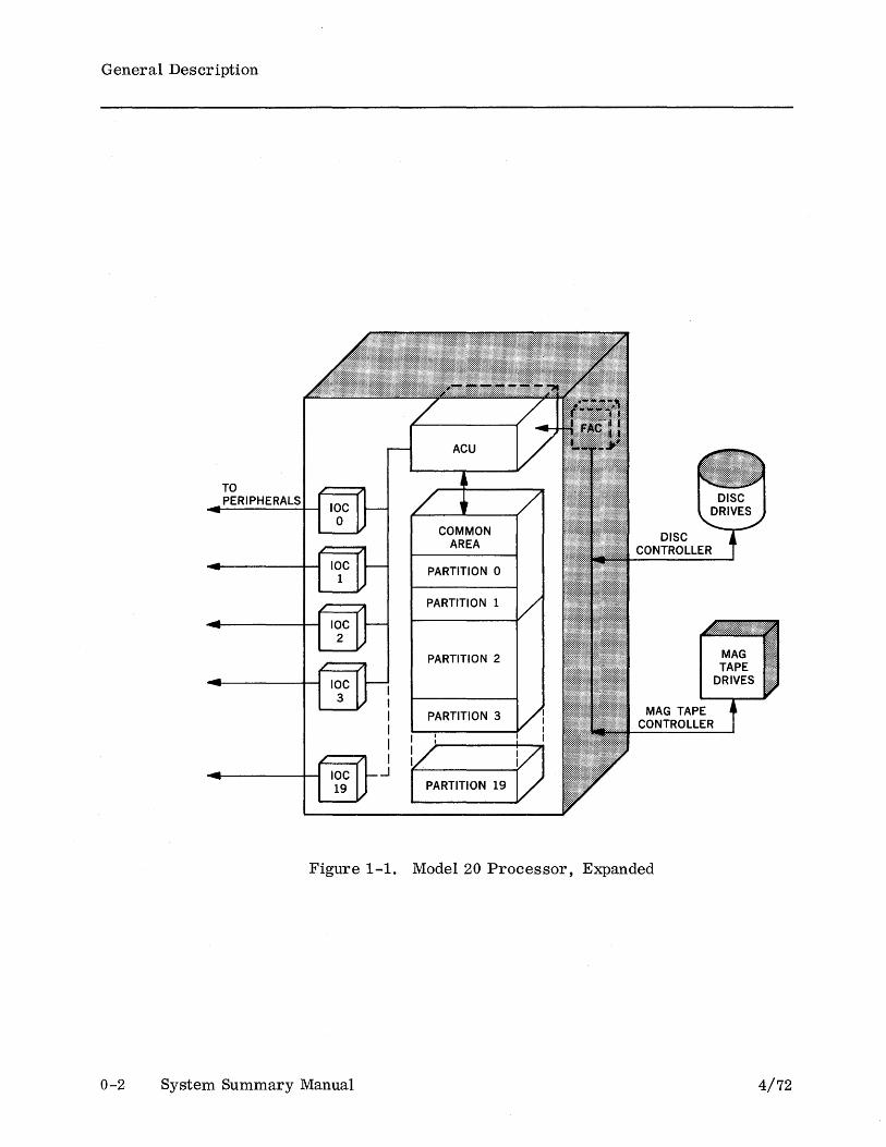
Figure 1-1. Model 20 Processor, Expanded
0-2 System Summary Manual
MAG TAPE
DRIVES
4/72

1 GENERAL DESCRIPTION
The System Ten computer provides a unique and inexpensive solution to the information processing needs of business and industry. It may be used as a batch processing system, as a multi-terminal data collection system, or it may combine both capabilities. As the processing requirements of a business change, the system may easily be expanded or altered to meet the current needs. The System Ten computer is also well-suited for use as a satellite of a larger computer.
The System Ten computer is a multi-programming system. A multi programming system is one which is capable of executing several independent programs concurrently (the System Ten computer can execute up to twenty). In the past, multi-programming systems have generally required a large and elaborate executive program. The.System Ten computer embodies a new approach. There is no executive program. All executive functions are performed by the hardware.
The type of facility provided by the System Ten computer is called fixed partition multi-programming because each program is assigned a fixed-size, contiguous area of main memory referred to as a user partition. A System Ten computer may contain up to twenty such partitions.
Unlike other multi -programming systems, the System Ten computer has an area of main memory, referred to as the Common partition (or Common), which is shared by all programs in the system. This makes it possible for otherwise independent programs to exchange information at main memory speeds and to share common subroutines. (See Figure 1-1.)
MEMORY ORGANIZATION
4/72
Main memory is purchased in units called core modules. Each. core module contains 10, 000 locations and each location accommodates one 6-bit character. A System Ten computer may contain a maximum of 110,000 locations.
When a System Ten computer is installed, main memory is divided among the various partitions so that the Common partition and each user partition are always some multiple of 1, 000 locations in size. The maximum allowable partition size is 10,000 locations. In every System Ten computer, at least 1,000 locations must be allocated to Common. Thus, a minimum configuration might contain one core module divided into a 1, OOO-location Common partition and a 9, OOO-location user partition.
Every location in main memory is addressable. Each is numbered consecutively within the Common partition and each user partition. The lowest address in any partition is always 0000 and the highest possible address is 9999.
System Summary Manual 1-1

General Description
Memory allocation is done by a Customer Service Representative at the time that the computer is installed. He can easily re-allocate memory whenever the need arises.
INPUT/OUTPUT FACILITIES
The transfer of data between main memory and peripheral devices is controlled by two types of input/ output channels. The File Access Channel (F AC) is designed to control the high-speed devices: disc drives and magnetic tape drives. The Input/ Output Channel (IOC) is designed to control the low-speed devices: card readers, card punches, line printers, paper tape readers, paper tape punches, CRT terminals, and input/output typewriters or workstations. Every System Ten computer has one FAC plus one to twenty lOCs.
Each user partition has its OWn IOC which can control up to ten low-speed devices. The devices attached to an IOC are directly accessible only to the program residing in the associated user partition. Each IOC device is assigned a I-digit device address from 0 through 9. Device 0 is of particular importance because this device is used for initiating the program loading process.
Unlike the IOCs, the FAC is a shared facility. The devices attached to the FAC are directly accessible to all programs in all partitions. Thus, several user partitions may share the same disc or magnetic tape files.
Depending upon what high-speed devices are included in the system, the F AC contains a Magnetic Tape Controller or a Disc Controller. The Magnetic Tape Controller can handle up to four tape drives, the Disc Controller up to ten disc drives. A particular System Ten configuration may contain both a Disc Controller and a Magnetic Tape Controller. Some special-purpose input/output channels may be included in a system in place of IOCs. For example, a synchronous communications adapter and an asynchronous communications adapter are available as well as a digital clock. Special-purpose channels are discussed in Section 2 of this manual.
HARDWARE OPERATING SYSTEM
1-2
A System Ten computer may include one to twenty user partitions (designated o through 19). The partitions share the processing capabilities of the Arithmetic and Control Unit (ACU). Priority for ACU processing time is controlled by the hardware. No software operating system is required.
The hardware uses a round-robin priority discipline. Each partition in turn is allotted up to 37 . 5 ms of ACU processing time. When this time has elapsed and a successful ''branch'' instruction is executed, the hardware automatically switches control to the next higher partition. Switching also occurs when the partition currently using the ACU initiates an IOC input/output operation. In addition, computer programs may cause switching to occur through use of a
System Summary Manual 4/72
General Description
special instruction. The partition that is using the ACU at any given time is referred to as the host partition.
When a partition initiates an IOC input/output operation, the hardware immediately switches control to the next higher partition. ACU processing time is not allotted to the previous parition again until the input/output operation is complete. The actual transferring of data is handled on a cycle-stealing basis. When a character of information is ready to be transferred between an IOC and the associated partition, the IOC interrupts normal processing long enough to complete the transfer. Normal processing continues after the character has been transferred.
When several partitions have IOC input/output operations in progress simultaneously, it is possible that two or more IOCs will attempt to interrupt normal processing at the same instant in time. If this occurs, the hardware responds to the interrupts in ascending sequence starting with IOC zero.
Unlike IOC operations, F AC data transfer operations are not overlapped with normal processing. When information is to be transferred between a partition and the F AC, all processing (except data transfers by IOC s) is suspended until the entire F AC input/output operation is complete.
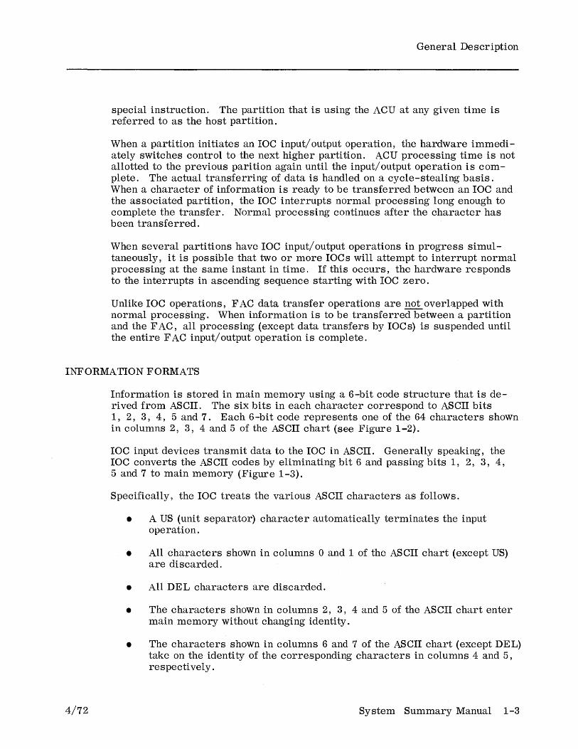
INFORMATION FORMATS
4/72
Information is stored in main memory using a 6-bit code structure that is derived from ASCII. The six bits in each character correspond to ASCII bits 1, 2, 3, 4, 5 and 7. Each 6-bit code represents one of the 64 characters shown in columns 2, 3, 4 and 5 of the ASCII chart (see Figure 1-2).
IOC input devices transmit data to the IOC in ASCII. Generally speaking, the IOC converts the ASCII codes by eliminating bit 6 and passing bits 1, 2, 3, 4, 5 and 7 to main memory (Figure 1-3).
Specifically, the IOC treats the various ASCII characters as follows.
• A US (unit separator) character automatically terminates the input operation.
• All characters shown in columns 0 and 1 of the ASCII chart (except US) are discarded.
• All DEL characters are discarded.
• The characters shown in columns 2, 3, 4 and 5 of the ASCII chart enter main memory without changing identity.
• The characters shown in columns 6 and 7 of the ASCII chart (except DEL) take on the identity of the corresponding characters in columns 4 and 5, respecti vely .
System Summary Manual 1-3

General Description
~ ~ 0 0 0 0 1 1 1 1
b6 .. 0 0 1 1 0 0 1 1 BI b5 • 0 1 0 1 0 1 0 1
~b4 b3 b2 b1
~ Row 0 1 2 3 4 5 6 7
0 0 0 0 0 NUL DLE SP 0 @ P , P
0 0 0 1 1 SOH DC1 ! 1 A Q a q
0 0 1 0 2 STX DC2 " 2 B R b r
0 0 1 1 3 ETX DC3 # 3 C S c s
0 1 0 0 4 EOT DC4 $ 4 D T d t
0 1 0 1 5 ENQ NAK % 5 E U e u
0 1 1 0 6 ACK SYN & 6 F V f v
0 1 1 1 7 BEL ETB , 7 G W g w
1 0 0 0 8 BS CAN ( 8 H X h x
1 0 0 1 9 HT EM ) 9 I Y i Y
1 0 1 0 10 LF SUB * : J Z j z
1 0 1 1 11 VT ESC + ; K [ k { 1 1 0 0 12 FF FS < L \ 1 I ,
I
1 1 0 1 13 CR GS - = M ] m } 1 1 1 0 14 SO RS > N ~ n ,....",
1 1 1 1 15 SI US / ? 0 0 DEL
Figure 1-2. ASCII Chart
ASCII
MAIN MEMORY
Figure 1-3. IOC Input Conversion
1-4 System Summary Manual 4/72
General Description
During output, the IOC converts each internal character to its corresponding ASCII code. An exception to this occurs when the special instruction "write control" is executed. In such a case, the characters shown in columns 4 and 5 of the ASCII chart are converted to the ASCII codes for the corresponding characters shown in columns 0 and 1, respectively (the characters shown in columns 2 and 3 are always converted without changing identity).
Data conversion during F AC input/output operations is somewhat different from that described above. For disc operations and for 7 -track magnetic tape operations, no ASCII conversion is performed (the data is essentially stored by the peripheral device in the 6-bit main memory form). For 9-track magnetic tape output operations, data is converted to ASCII and then written on the tape in a format compatible with that used by most other manufacturers' tape drives.
The System Ten computer is designed to operate upon variable-length' fields. The number of characters involved in any given operation ranges from 1 to 10, 1 to 100, or 1 to 10,000 depending upon the particular instruction being executed.
Fields are groups of contiguous locations in main memory. An instruction defines the field to be operated upon by specifying the address of the lowest location (leftmost character) in the field. In the case of numeric operands, this location corresponds to the most significant digit position in the field. Some instructions, such as the arithmetic instructions, operate upon two fields. In such cases, the instruction defines each field in the above manner.
If a field is to be used as a numeric field, only bits 1, 2, 3 and 4 of each character in the field are used in the operation. However, bit 7 of the highest location (rightmost character or least significant digit) in the field is used for specifying the sign of the field. If bit 7 is a one, the field is considered to contain a negative value; if bit 7 is a zero, the field is considered to contain a positive value.
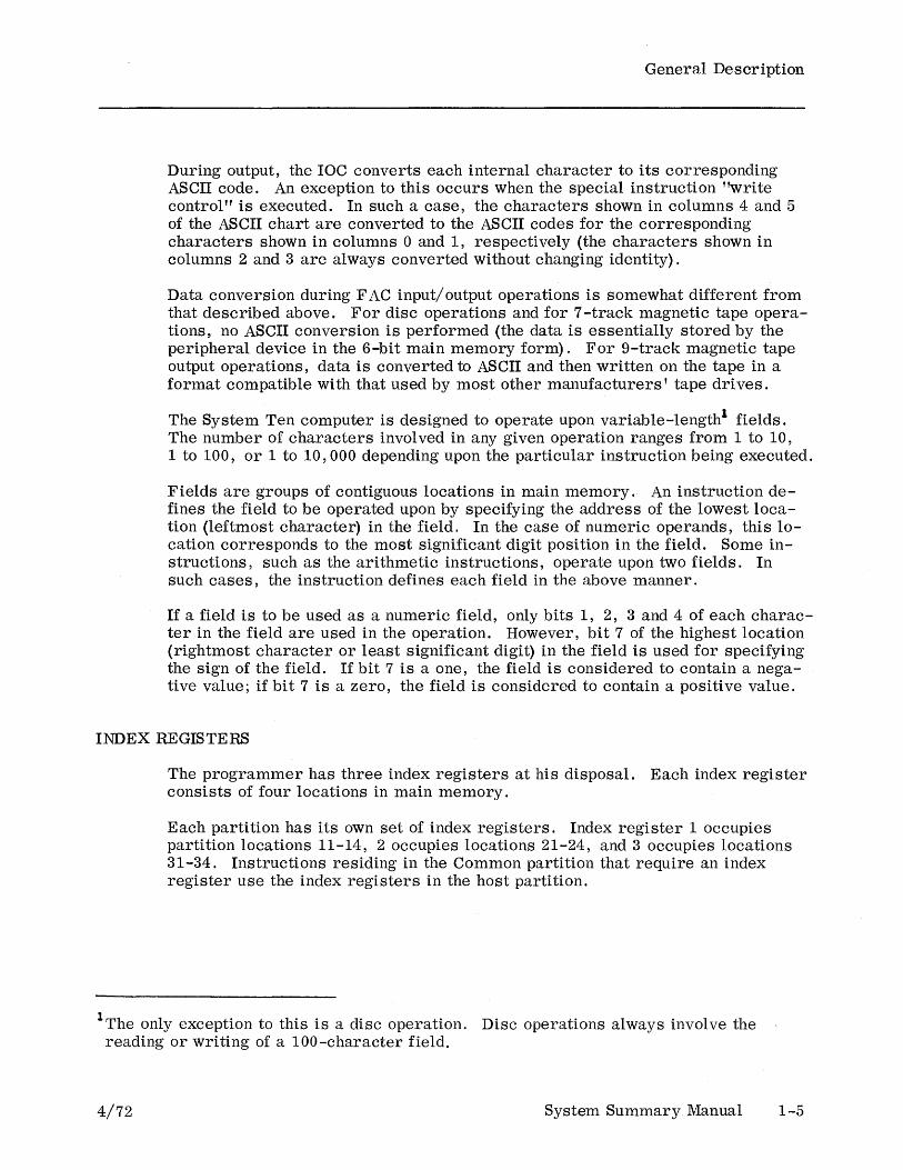
INDEX REGISTERS
The programmer has three index registers at his disposal. Each index register consists of four locations in main memory.
Each partition has its own set of index registers. Index register 1 occupies partition locations 11-14, 2 occupies locations 21-24, and 3 occupies locations 31-34. Instructions residing in the Common partition that require an index register use the index registers in the host partition.
lThe only exception to this is a disc operation. Disc operations always involve the reading or writing of a 100-character field.
4/72 System Summary Manual 1-5
General Description
Since the index registers are in main memory, no special index register instructions are required. Index register manipulation and testing are done using normal System Ten instructions. When instructed to do so, the System Ten computer will automatically perform address modification using the contents of an index register.
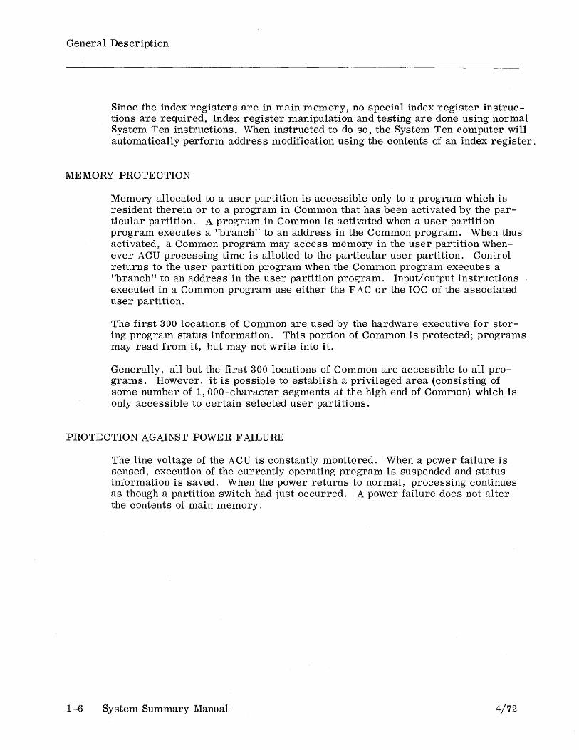
MEMORY PROTECTION
Memory allocated to a user partition is accessible only to a program which is resident therein or to a program in Common that has been activated by the particular partition. A program in Common is activated when a user partition program executes a ''branch'' to an address in the Common program. When thus activated, a Common program may access memory in the user partition whenever ACU processing time is allotted to the particular user partition. Control returns to the user partition program when the Common program executes a "branch" to an address in the user partition program. Input/output instructions executed in a Common program use either the F AC or the IOC of the associated user partition.
The first 300 locations of Common are used by the hardware executive for storing program status information. This portion of Common is protected; programs may read from it, but may not write into it.
Generally, all but the first 300 locations of Common are accessible to all programs. However, it is possible to establish a privileged area (consisting of some number of 1, OOO-character segments at the high end of Common) which is only accessible to certain selected user partitions.
PROTECTION AGAINST POWER F AlLURE
1-6
The line voltage of the ACU is constantly monitored. When a power failure is sensed, execution of the currently operating program is suspended and status information is saved. When the power returns to normal, processing continues as though a partition switch had just occurred. A power failure does not alter the contents of main memory.
System Summary Manual 4/72
4/72
2 HARDWARE CAPABILITIES
This section summarizes the available peripheral devices and special-purpose input/ output channels for the System Ten computer. Related publications are listed in the Appendix.
System Summary Manual 2-1

Hardware Capabilities
MODEL 20 PROCESSOR
The Model 20 Processor is a time-sharing processor that can handle up to twenty jobs concurrently by means of hardware control; it does not require a software executive program. The processor is modular so that its multiprogramming capability can be increased by adding additional input/output channels and core memory storage. Section 1 of this manual gives further information on the concepts, characteristics, and capabilities of the system.
Equipment Characteristics
Organization
Decimal, variable field
Command repertoire
13 basic instructions including hardware multiply and divide
Internal code
6 -bit subset of ASCII code
Core memory size
10,000 characters, expandable in 10,000-character modules to 110,000 characters
Core memory cycle time
3.3 microseconds
Input/Output channels
Up to 20 (each channel may be associated with one user program. Each input/output channel in turn may control up to ten devices.)
Controllers
Communications, disc, and magnetic tape
There are three basic Model 20 Processor configurations, the Series 102, 104 and 106. Each of these has been designed for a specific application. System configurations are described below; system components are described individually in the rest of this section.
SERIES 102
This 10K configuration uses either the Model 70 Workstation or the Model 80 Display as an input device, thus eliminating the need for punch card or other processing equipment. It can be used by the smaller business that has relatively uncomplicated applications and that does not have or need a programming staff. The system can be expanded easily to fit future applications.
Minimum Configuration
One Model 20-102 Processor
2-2 System Summary Manual
10K of Core One FAC One Disc Controller One IOC
4/72
Hardware Capabilities
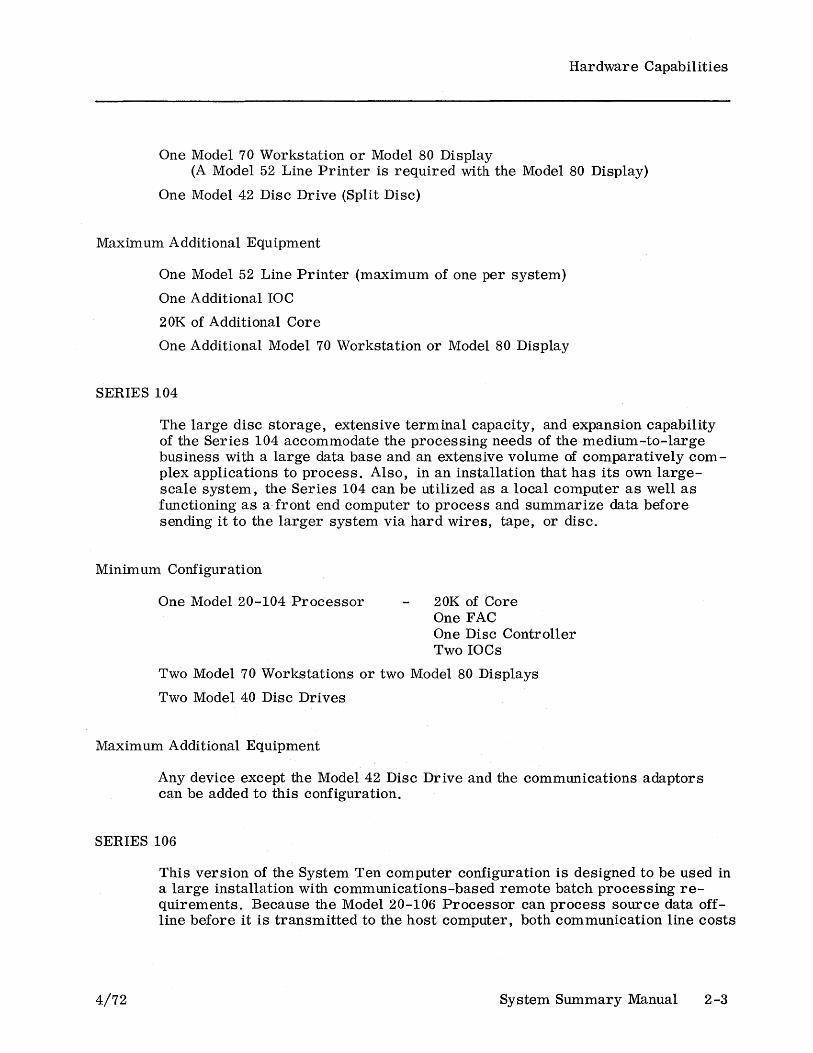
One Model 70 Workstation or Model 80 Display (A Model 52 Line Printer is required with the Model 80 Display)
One Model 42 Disc Drive (Split Disc)
Maximum Additional Equipment
One Model 52 Line Printer (maximum of one per system)
One Additional roc 20K of Additional Core
One Additional Model 70 Workstation or Model 80 Display
SERIES 104
The large disc storage, extensive terminal capacity, and expansion capability of the Series 104 accommodate the processing needs of the medium-to-Iarge business with a large data base and an extensive volume of comparatively complex applications to process. Also, in an installation that has its own largescale system, the Series 104 can be utilized as a local computer as well as functioning as a, front end computer to process and summarize data before sending it to the larger system via hard wires, tape, or disc.
Minimum Configuration
One Model 20-104 Processor 20K of Core One FAC One Disc Controller Two IOCs
Two Model 70 Workstations or two Model 80 Displays
Two Model 40 Disc Drives
Maximum Additional Equipment
Any device except the Model 42 Disc Drive and the communications adaptors can be added to this configuration.
SERIES 106
4/72
This version of the System Ten computer configuration is designed to be used in a large installation with communications-based remote batch processing requirements. Because the Model 20-106 Processor can process source data offline before it is transmitted to the host computer, both communication line costs
System Summary Manual 2-3

Hardware Capabilities
and computer costs are decreased. A wide variety of terminals and communications devices is available.
Minimum Configuration
One Model 20-106 Processor
One SCA, One ATA, or One ACA
One I/O Device
20 K of Core One FAC* One Disc Controller* Three lOCs
Maximum Additional Equipment
Any System Ten peripheral device can be added to the Model 20-106. Maximum core capacity is 110K.
*For non-disc communications systems, delete the FAC and the Disc Controller.
2-4 System Summary Manual 4/72
Hardware Capabilities
MODEL 30 CARD READER
4/72
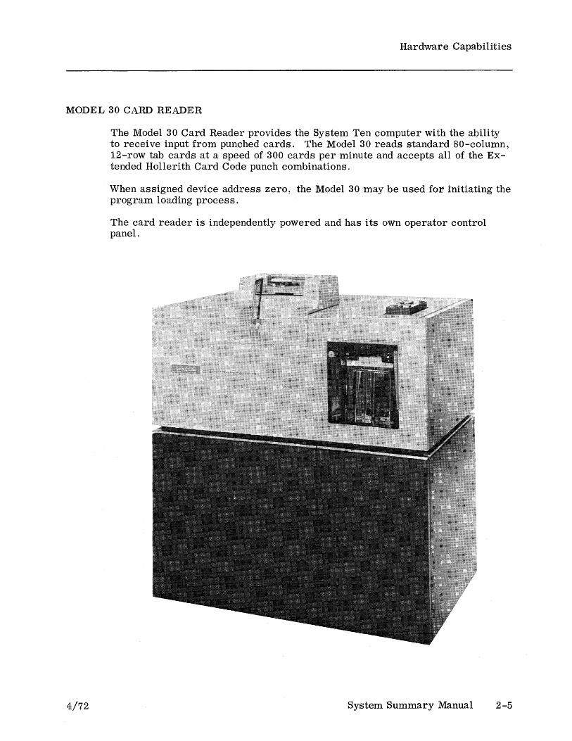
The Model 30 Card Reader provides the System Ten computer with the ability to receive input from punched cards. The Model 30 reads standard SO-column, 12-row tab cards at a speed of 300 cards per minute and accepts all of the Extended Hollerith Card Code punch combinations.
When assigned device address zero, the Model 30 may be used for initiating the program loading process.
The card reader is independently powered and has its own operator control panel.
System Summary Manual 2-5

Hardware Capabilities
MODEL 35 CARD PUNCH
The Model 35 Card Punch provides the System Ten computer with the ability to produce output in the form of punched cards. The Model 35 punches output data in the Extended Hollerith Card Code on standard 80-column, 12-row tab cards at a speed of 100 cards per minute. The Model 35 can punch all of the negative number combinations (in some accounting environments, an 11-punch in the same column with a numeric punch indicates that the number is a negative number).
The card punch is independently powered and has its own operator control panel.
2 -6 System Summary Manual 4/72
Hardware Capabilities
MODEL 40 DISC DRIVE
4/72
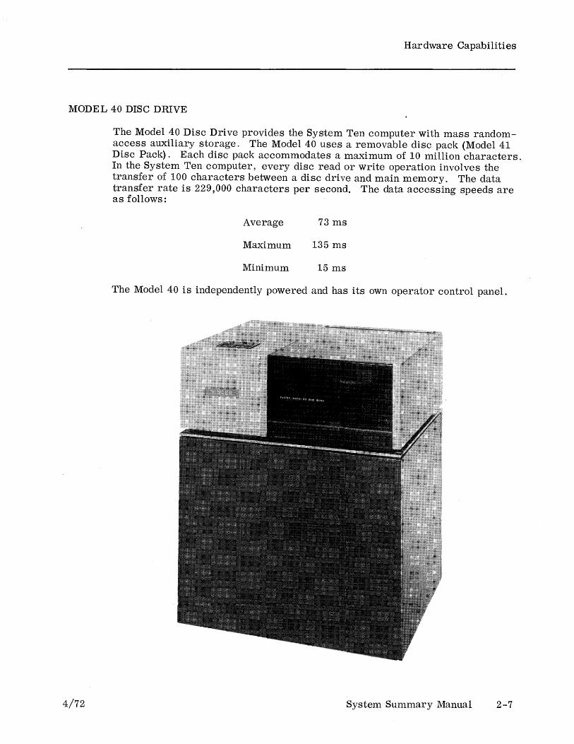
The Model 40 Disc Drive provides the System Ten computer with mass randomaccess auxiliary storage. The Model 40 uses a removable disc pack (Model 41 Disc Pack). Each disc pack accommodates a maximum of 10 million characters. In the System Ten computer, every disc read or write operation involves the transfer of 100 characters between a disc drive and main memory. The data transfer rate is 229,000 characters per second. The data accessing speeds are as follows:
Average 73 ms
Maximum 135 ms
Minimum 15 ms
The Model 40 is independently powered and has its own operator control panel.
System Summary Manual 2-7
Hardware Capabilities
MODEL 42 DISC DRIVE
2-8
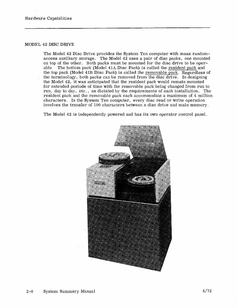
The Model 42 Disc Drive provides the System Ten computer with mass randomaccess auxiliary storage. The Model 42 uses a pair of disc packs, one mounted on top of the other. Both packs must be mounted for the disc drive to be operable The bottom pack (Model 41A Disc Pack) is called the resident pack and the top pack (Model 41B Disc Pack) is called the removable pack. Regardless of the terminology, both packs can be removed from the disc drive. In designing the Model 42, it was anticipated that the resident pack would remain mounted for extended periods of time with the removable pack being changed from run to run, day to day, etc., as dictated by the requirements of each installation. The resident pack and the removable pack each accommodate a maximum of 4 million characters. In the System Ten computer, every disc read or write operation involves the transfer of 100 characters between a disc drive and main memory,
The Model 42 is independently powered and has its own operator control panel.
System Summary Manual 4/72

Hardware Capabilities
MODEL 45 MAGNETIC TAPE DRIVE
4/72
The Model 45 Magnetic Tape Drive provides the System Ten computer with magnetic tape input/output capability. The Model 45 reads and writes in a format compatible with most other manufacturers f drives, thus allowing it to be used for inter-system communication. In addition, the Model 45 may be used for intermediate storage, for archive (permanent) storage, or as backup for disc packs.
The Model 45 is available either as a 7 -track or a 9-track drive. Rated transfer speeds are:
9-track: 20,000 characters per second, maximum
7-track: 20,000 or 13,900 characters per second, maximum
The Model 45 normally reads and writes in ASCII (in the case of 7 -track drives, the 6-bit System Ten computer ASCII subset). with a 9-track drive, the computer program may read or write unsigned numeric data in packed format or read or write 8-bit codes such as EBCDIC by using a special mode called the double frame mode.
With 7-track drives, the recording density (556 or 800 BPI) is selectable through a switch on the front of the drive. With 9-track drives, the recording density is always 800 BPI. Tape drive device numbers are also selectable through switches on the front of the drive.
The Model 45 is independently powered and has its own operator control panel.
System Summary Manual 2-9

Hardware Capabilities
MODEL 50 LINE PRINTER
2-10
The Model 50 Line Printer provides the System Ten computer with the ability to produce printed output on continuous paper forms at a speed of 225-450 lines per minute. The line length is 132 characters. Character spacing is ten to the inch across the page and six to the inch down the page. The standard print set consists of those characters shown in columns 2, 3, 4 and 5 of the ASCII chart with the following two exceptions:
• An t prints instead of 1\
• An -+- prints instead of _
For information about alternate (international) print sets, see a Singer Field Engineer.
The line printer is independently powered and has its own operator control panel.
System Summary Manual 4/72

Hardware Capabilities
MODEL 52 LINE PRINTER
4/72
The Model 52 Line Printer provides the System Ten computer with the ability to produce printed output on continuous paper forms at a speed of 90-110 lines per minute. The line length is 132 characters. Character spacing is ten to the inch across the page and six to the inch down the page. The standard print set consists of those characters shown in columns 2, 3, 4, and 5 of the ASCII chart. For information about alternate (international) print sets, see a Singer Field Engineer.
The line printer is independently powered and has its own operator control panel.
System Summary Manual 2-11
Hardware Capabilities
MODEL 60 PAPER TAPE READER
2-12
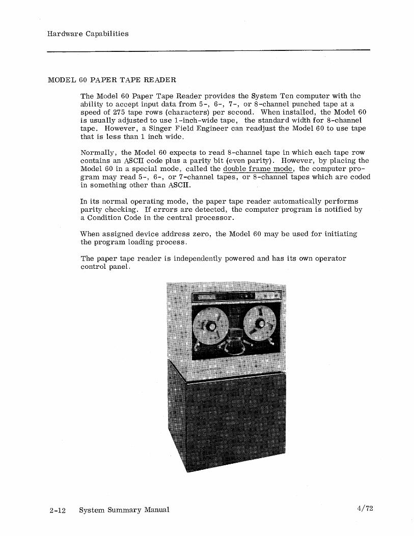
The Model 60 Paper Tape Reader provides the System Ten computer with the ability to accept input data from 5-, 6-, 7-, or 8-channel punched tape at a speed of 275 tape rows (characters) per second. When installed, the Model 60 is usually adjusted to use 1-inch-wide tape, the standard width for 8-channel tape. However, a Singer Field Engineer can readjust the Model 60 to use tape that is less than 1 inch wide.
Normally, the Model 60 expects to read 8-channel tape in which each tape row contains an ASCII code plus a parity bit (even parity). However, by placing the Model 60 in a special mode, called the double frame mode, the computer program may read 5-, 6-, or 7-channel tapes, or 8-channel tapes which are coded in something other than ASCII.
In its normal operating mode, the paper tape reader automatically performs parity checking. If errors are detected, the computer program is notified by a Condition Code in the central processor.
When assigned device address zero, the Model 60 may be used for initiating the program loading process.
The paper tape reader is independently powered and has its own operator control panel.
System Summary Manual 4/72

Hardware Capabilities
MODEL 65 PAPER TAPE PUNCH
4/72
The Model 65 Paper Tape Punch provides the System Ten with the ability to produce output in the form of punched tape at a speed of 150 tape rows (characters) per second.· When installed, the Model 65 is usually adjusted to use 1-inch-wide tape, the standard width for 8-channel tape. However, the computer operator can readjust the Model 65 to use tape which is less than 1 inch wide.
Normally, the Model 65 punches 8-channel tape in which each tape row contains an ASCII code plus a parity bit (even parity) However, by placing the Model 65 in a special mode, called the double frame mode, the computer program may punch 5-, 6-, or 7-channel tapes, or 8-channel tapes which are coded in something other than ASCII.
The paper tape punch is independently powered and has its own operator control panel.
System Summary Manual 2-13
Hardware Capabilities
MODEL 70 WORKSTATION
2-14
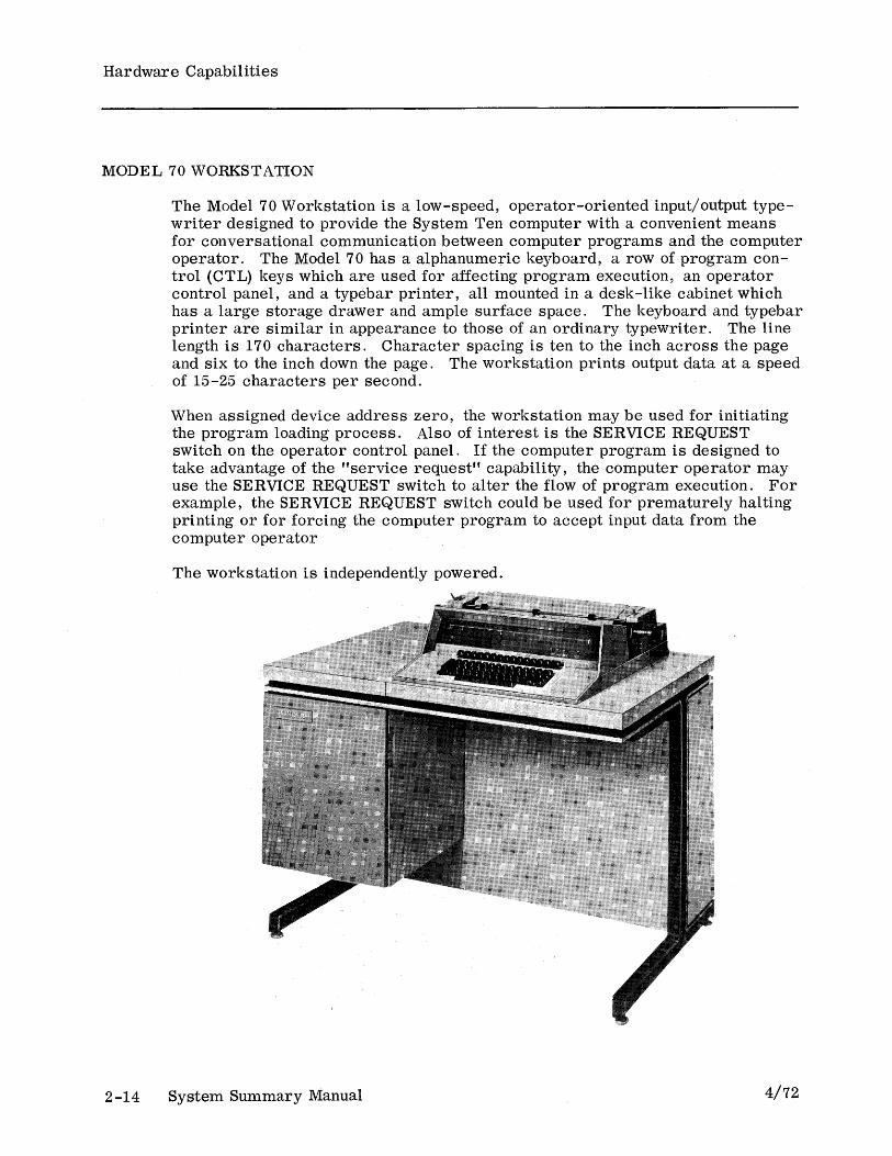
The Model 70 Workstation is a low-speed, operator-oriented input/output typewriter designed to provide the System Ten computer with a convenient means for conversational communication between computer programs and the computer operator. The Model 70 has a alphanumeric keyboard, a row of program control (CTL) keys which are used for affecting program execution, an operator control panel, and a typebar printer, all mounted in a desk-like cabinet which has a large storage drawer and ample surface space. The keyboard and typebar printer are similar in appearance to those of an ordinary typewriter. The line length is 170 characters. Character spacing is ten to the inch across the page and six to the inch down the page. The workstation prints output data at a speed of 15-25 characters per second.
When assigned device address zero, the workstation may be used for initiating the program loading process. Also of interest is the SERVICE REQUEST switch on the operator control panel. If the computer program is designed to take advantage of the "service request" capability, the computer operator may use the SERVICE REQUEST switch to alter the flow of program execution. For example, the SERVICE REQUEST switch could be used for prematurely halting printing or for forcing the computer program to accept input data from the computer operator
The workstation is independently powered.
System Summary Manual 4/72

Hardware Capabilities
MODEL 80 DISPLAY
4/72
The Model 80 Display is a cathode ray tube input/output console designed to provide the System Ten computer with a convenient means for conversational communication between computer programs and the computer operator. The screen accommodates 20 lines, 80 characters per line. When the power is on, a blinking marker called a cursor shows where the next character will be displayed. The Model 80 has a full page (1600 character) buffer. In addition to a full alphanumeric keyboard, the Model 80 has a 10-key numeric keyboard which is similar to those used on many adding machines and calculators, a set of cursor control keys, a set of editing control keys (INSERT LINE, INSERT SPACE, DELETE LINE, DELETE SPACE, and ERASE), and a set of program control (CTL) keys which are used for affecting program execution. The Model 80 is a free.-standing unit which is compact enough to fit on the top of an ordinary desk.
When assigned device address zero, the Model 80 may be used for initiating the program loading process.
Under program control, the user may establish protected fields. A protected field cannot be destroyed either by operator entry or by a Write instruction. If the cursor encounters a protected field, the cursor automatically skips over the protected field (after the cursor movement is finished, the operation in progress continues). Protected fields are displayed with underscoring to differentiate them from unprotected data.
The Model 80 is independently powered.
System Summary Manual 2-15
Hardware Capabilities
MODEL 100 JOB INFORMATION STATION
2-16
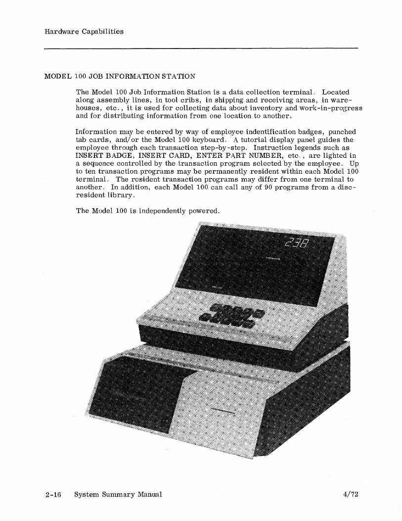
The Model 100 Job Information Station is a data collection terminal. Located along assembly lines, in tool cribs, in shipping and receiving areas, in warehouses, etc., it is used for collecting data about inventory and work-in-progress and for distributing information from one location to another.
Information may be entered by way of employee indentification badges, punched tab cards, and/or the Model 100 keyboard. A tutorial display panel guides the employee through each transaction step-by-step. Instruction legends such as INSERT BADGE, INSERT CARD, ENTER PART NUMBER, etc., are lighted in a sequence controlled by the transaction program selected by the employee. Up to ten transaction programs may be permanently resident wi thin each Model 100 terminal. The resident transaction programs may differ from one terminal to another. In addition, each Model 100 can call any of 90 programs from a discresident library.
The Model 100 is ind~pendently powered.
System Summary Manual 4/72
Hardware Capabilities
MODEL 105 ATTENDANCE STATION
4/72
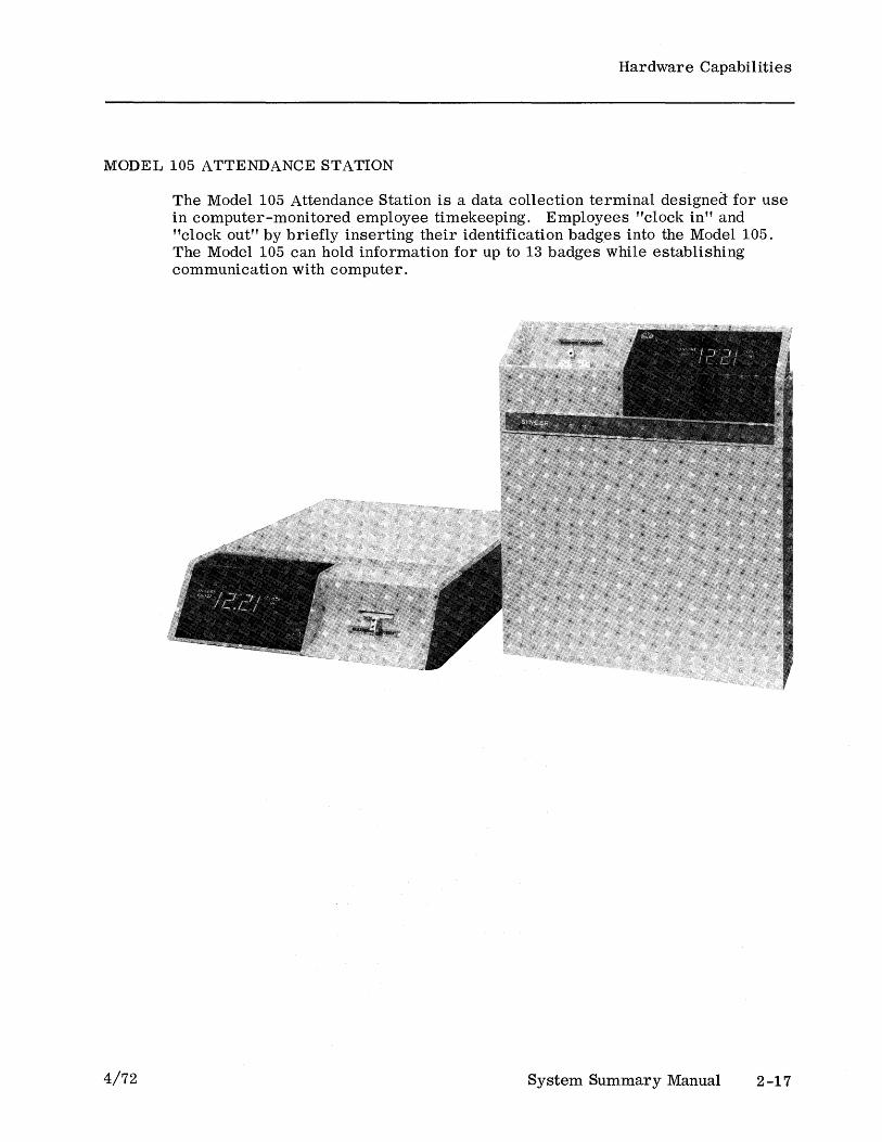
The Model 105 Attendance Station is a data collection terminal designed for use in computer-monitored employee timekeeping. Employees "clock in" and "clock out" by briefly inserting their identification badges into the Model 105. The Model 105 can hold information for up to 13 badges while establishing communication with computer.
System Summary Manual 2-17
Hardware Capabilities
MODEL 191 LINE SWITCIITNG UNIT (LSU)
2-18
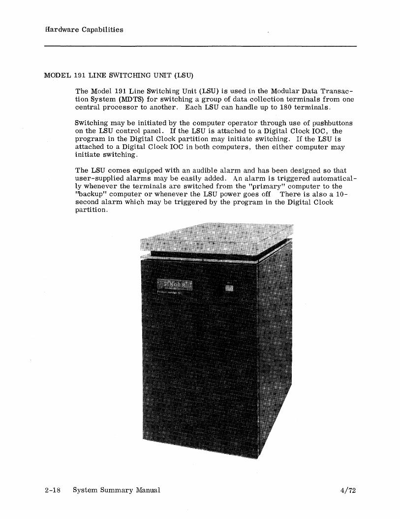
The Model 191 Line Switching Unit (LSU) is used in the Modular Data Transaction System (MDTS) for switching a group of data collection terminals from one central processor to another. Each LSU can handle up to 180 terminals.
Switching may be initiated by the computer operator through use of pushbuttons on the LSU control panel. If the LSU is attached to a Digital Clock IOC, the program in the Digital Clock partition may initiate switching. If the LSU is attached to a Digital Clock IOC in both computers, then either computer may initiate switching.
The LSU comes equipped with an audible alarm and has been designed so that user-supplied alarms may be easily added. An alarm is triggered automatically whenever the terminals are switched from the "primary" computer to the ''backup'' computer or whenever the LSU power goes off There is also a 10-second alarm which may be triggered by the program in the Digital Clock partition.
System Summary Manual 4/72

Hardware Capabilities
MODEL 800 INDIVIDUAL STORE AND FORWARD (ISF) MODULE
4/72
The Model 800 Individual Store and Forward (ISF) Module is a portable magnetic tape device designed for use in conjunction with a Model 900 Data Terminal. The ISF receives data from a Model 900, stores the data, and then transmits the data through a modem to a remote computer whenever the computer requests that the data be transmitted. The ISF transmits the data in asynchronous format. New data may be recorded while previously recorded data is being transmi tted.
The ISF resembles a small suitcase and can be used as a free-standing unit on the floor or on a shelf, or can be hung on a wall by using a special bracket. A handle on the top of the ISF allows the unit to be carried from place to place.
System Summary Manual 2-19

Hardware Capabilities
MODEL 850 ASYNCHRONOUS TO SYNCHRONOUS TRANSMISSION ADAPTER (ASTA)
2-20
The Model 850 Asynchronous to Synchronous Transmission Adapter (ASTA) is a code conversion unit designed to serve as an interface between Model 800 Individual Store and Forward (ISF) Modules and the synchronous communications channel of a computer.
ISF Modules transmit data in asynchronous format. The ASTA accepts the data, converts it to synchronous format, and transmits the data to the computer. The ASTA accepts data at 1200 bits per second and transmits it at 1800 bits per second.
A typical ISF -ASTA -computer configuration might be as follows:
ISF
I 202E (or equivalent) Data Set
I Telephone N etwor k
I 202C (or equivalent) Data Set
I
ASTA
I Synchronous communications
channel of the computer
System Summary Manual
This data set must be capable of transmitting data at 1200 bits per second and receiving a 5-baud reverse channel signal.
This data set must be capable of receiving and transmitting data at 1200 bits per second and of transmitting a 5-baud reverse channel signal.
4/72
Hardware Capabilities
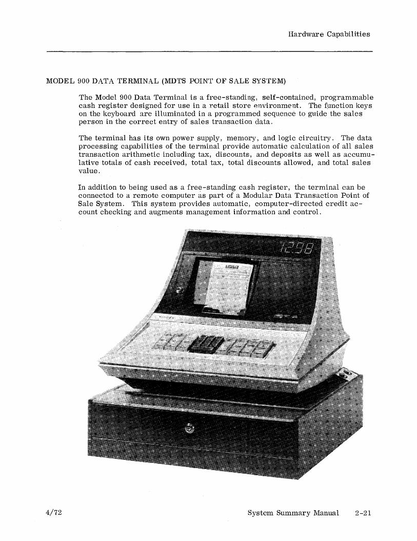
MODEL 900 DATA TERMINAL (MDTS POINT OF SALE SYSTEM)
4/72
The Model 900 Data Terminal is a free-standing, self-contained, programmable cash register designed for use in a retail store environment. The function keys on the keyboard are illuminated in a programmed sequence to guide the sales person in the correct entry of sales transaction data.
The terminal has its own power supply, memory, and logic circuitry. The data processing capabilities of the terminal provide automatic calculation of all sales transaction arithmetic including tax, discounts, and deposits as well as accumulative totals of cash received, total tax, total discounts allowed, and total sales value.
In addition to being used as a free-standing cash register, the terminal can be connected to a remote computer as part of a Modular Data Transaction Point of Sale System. This system provides automatic, computer-directed credit account checking and augments management information and control.
System Summary Manual 2-21
Hardware Capabilities
SYNCHRONOUS COMMUNICATIONS ADAPTER (SCA)
This special-purpose input/ot!tput channel makes it possible for programs in a System Ten computer to exchange data with programs in remote computers via voice-grade communications lines. The SCA is designed to be used in accordance with the rules for binary synchronous communications. An SCA replaces two regular IOCs 1 and has one user partition attached to it. Other user partitions receive data from the SCA partition (or vice versa) either through Common or by way of disc or magnetic tape.
A Bell System Series 201 (or equivalent) modem must be connected at each end of the communications line. When transmission is over a dedicated line, the transmission rate is 2400 bits per second (transmission may take place at speeds up to 9600 bps if non-Bell System data sets are used). When transmission is over the switched (DDD) telephone network, the transmission rate is 2000 bits per second.
The SCA uses half-duplex 2, dedicated (private or leased) lines or the switched telephone network. When connected to the switched telephone network, the SCA has automatic answering and disconnect capability. In addition, if it has a Bell System Series 801 Automatic Calling Unit attached to it, the SCA includes program -ini tiated dialing capability.
lIf it is installed so that it replaces user partition 19, the SCA can be installed in such a way that it replaces only one regular IOC.
2A half-duplex circuit is designed for transmission in either direction but not both directions simultaneously. --
2-22 System Summary·Manual 4/72

Hardware Capabilities
ASYNCHRONOUS COMMUNICATIONS ADAPTER (ACA)
This special-purpose input/output channel makes it possible for programs in a System Ten computer to receive data from Model 800 Individual Store and Forward (ISF) Modules or to receive data from and send data to asynchronous ASCII terminals, by way of voice-grade communications lines. An ACA replaces two regular tOCs 1 and has one user partition attached to it. Other user partitions receive data from the ACA partition (or vice versa) either through Common or by way of disc or magnetic tape.
In the ISF Mode, the nominal transmission rate is 1200 bits per second. In the non-ISF Mode, the nominal transmission rate is 150, 300, 600, 1200, or 1800 bits per second. The mode of operation (ISF or non-ISF) and the transmission rate are selectable under program control. The ACA sends, and expects to receive, data characters in a 10-bit format: a START bit, a 7-bit ASCII code, a PARITY bit, and a STOP bit.
A Bell System Series 202 (or equivalent) modem must be connected at each end of the communications line.
The ACA uses half-duplex 2, dedicated (private or leased) lines or the switched
(DDD) telephone network. When connected to the switched telephone network, the ACA has automatic answering capability. In addition, the ACA includes program-initiated dialing capability if it has a Bell System Series 801 Automatic Calling Unit attached to it.
1 If it is installed so that it replaces user partition 19, the ACA can be installed in such a way that it replaces only one regular IOC.
2 A half-duplex circuit is designed for transmission in either direction but not both directions simultaneously. --
4/72 System Summary Manual 2-23
Hardware Capabilities Hardware Capabilities
ASYNCHRONOUS TERMINAL ADAPTER (ATA)
This special-purpose input/output channel makes it possible for programs in a System Ten computer to receive data from and send data to asynchronous operator-oriented ASCII terminals via voice-grade communications lines. Some examples of these terminals are the Models 33 , 35, and 37 Teletypewriters, and the Singer Model 7102 Communications Terminal. An ATA replaces one regular IOC 1 and has one user partition attached to it. Other user partitions receive data from the ATA partition (or vice versa) either through Common or by way of disc or magnetic tape.
The nominal transmission rate is 110, 150, 200, or 300 bits per second (the rate is established by a hard-wired connection at the time the ATA is installed). The ATA sends, and expects to receive, data characters in a 10-bit format: a START bit, a 7 -bit ASCII code, a PARITY bit, and a STOP bit. At the 110 bps transmission rate, an extra STOP bit is included in order to be compatible with terminals that operate -at that speed.
The terminal can be directly connected to the ATA if the connecting line does not exceed 50 feet. Otherwise, a Bell System Series 103 (or equivalent) modem must be connected at each end of the line.
The ATA can use half-duplex2 , dedicated (private or leased) lines or the switched (DDD) telephone network. When connected to the switched telephone network, the ATA has automatic answering and disconnect capability. In addition, the ATA includes program-initiated dialing capability, if it has a Bell System Series 801 Automatic Calling Unit attached to it.
lIf automatic dialing is provided for, two IOCs will be replaced. However, if it replaces user partition 19, the ATA can be installed in such a way that it replaces only one regular IOC.
2 A half-duplex circuit is designed for transmission in either direction but not both directions simultaneously. --
2-24 System Summary Manual 4/72
Hardware Capabilities Hardware Capabilities
MODULAR DATA SYSTEMS (MDS) INPUT/OUTPUT CHANNEL
4/72
This special-purpose input/output channel is used in the Modular Data Transaction System (MDTS).
An MDS IOC replaces one regular IOC and has one user partition attached to it. Each MDS IOC may have as many as ten of the following devices attached to it:
• Model 900 Data Terminal
• Model 100 Job Information Station
• Model 105 Attendance Station
Each device may be located up to 8 wire-miles from the central processor.
System Summary Manual 2-25

Hardware Capabilities Hardware Capabilities
DIGITAL CLOCK INPUT/OUTPUT CHANNEL
2-26
This special-purpose input/output channel provides th.e System Ten computer with a lO-second hardware clock. The Digital Clock icc replaces one regular IOC and has one user partition attached "to it. The only equipment which may be attached to a Digital Clock IOC is a Model 191 Line Switching Unit (LSU) or an External Clock Interface.
The Digital Clock IOC records elapsed time up to a maximum of ten seconds. The program that resides in the Digital Clock partition executes a special instruction to read this time and then stores it in Common so that it will be available to other partitions. When the program has read the time, the Digital Clock IOC begins another cycle starting from zero.
The Digital Clock IOC has a pair of electrical relays to which user-supplied audible alarms may be attached. One of the relays is activated (for ten seconds) under program control. The other relay is activated automatically whenever the central processor's main power goes off or when ever ten seconds elapse without the time being read by the program.
System Summary Manual 4/72

Hardware Capabilities Hardware Capabilities
EXTERNAL CLOCK INTERF ACE (ECI)
4/72
The External Clock Interface (ECI) is a free-standing, self-contained unit which serves as an interface between the Digital Clock laC of a System Ten computer and most Factory Master Clock systems.
A Factory Master Clock system periodically synchronizes all the clocks which are attached to it. The ECI synchronizes a software clock, located in Common, with the extBrnal clocks. The ECI accepts the synchronization signals from the Factory Master Clock system and generates hourly or 12-hour signals to which the software clock is synchronized.
The ECI is independently powered. The only external control on the Eel is a POWER ON/OFF switch.
System Summary Manual 2-27

4/72
3 SOFTWARE CAPABILITIES
This section summarizes the available supported software for the System Ten computer. The software discussed is divided into four types: Disc Management Facility (DMF) Software, Basic Software, Communications (COM) Software, and Miscellaneous Software. The applicable type is indicated at the top of each page. Related publications are listed in the Appendix.
System Summary Manual 3-1
Software Capabilities (DMF)
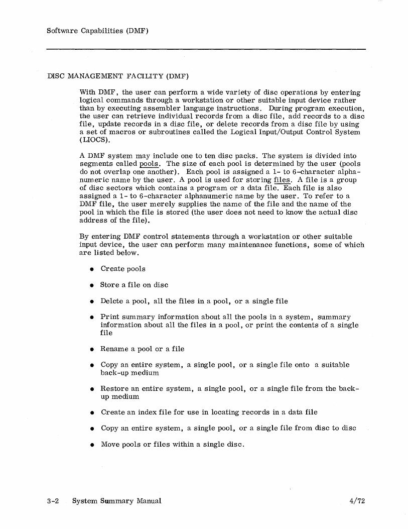
DISC MANAGEMENT FACILITY (DMF)
3-2
With DMF, the user can perform a wide variety of disc operations by entering logical commands through a workstation or other suitable input device rather than by executing assembler language instructions. During program execution, the user can retrieve individual records from a disc file, add records to a disc file, update records in a disc file, or delete records from a disc file by using a set of macros or subroutines called the Logical Input/Output Control System (LIOCS).
A DMF system may include one to ten disc packs. The system is divided into segments called pools. The size of each pool is determined by the user (pools do not overlap one another). Each pool is assigned a 1- to 6-character alphanumeric name by the user. A pool is used for storing files. A file is a group of disc sectors which contains a program or a data file. Each file is also assigned a 1- to 6-character alphanumeric name by the user. To refer to a DMF file, the user merely supplies the name of the file and the name of the pool in which the file is stored (the user does not need to know the actual disc address of the file).
By entering DMF control statements through a workstation or other suitable input device, the user can perform many maintenance functions, some of which are listed below.
• Create pools
• Store a file on disc
• Delete a pool, all the files in a pool, or a single file
• Print summary information about all the pools in a system, summary information about all the files in a pool, or print the contents of a single file
• Rename a pool or a file
• Copy an entire system, a single pool, or a single file onto a suitable back-up medium
• Restore an entire system, a single pool, or a single file from the backup medium
• Create an index file for use in locating records in a data file
• Copy an entire system, a single pool, or a single file from disc to disc
• Move pools or files within a single disc.
System Summary Manual 4/72
Software Capabilities (DMF)
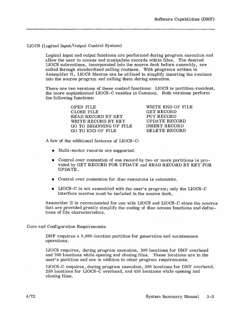
LIOCS (Logical Input/Output Control System)
Logical input and output functions are performed during program execution and allow the user to access and manipulate records within files. The desired LIOCS subroutines, incorporated into the source deck before assembly, are called through standardized calling routines. With programs written in Assembler II, LIOCS Macros can be utilized to simplify inserting the routines into the source program and calling them during execution.
There are two versions of these control functions: LIOCS is partition-resident, the more sophisticated LIOCS-C resides in Common. Both versions perform the following functions:
OPEN FILE CLOSE FILE READ RECORD BY KEY WRITE RECORD BY KEY GO TO BEGINNING OF FILE GO TO END OF FILE
A few of the additional features of LIOCS-C:
• Multi-sector records are supported.
WRITE END OF FILE GET RECORD PUT RECORD UPDATE RECORD INSERT RECORD DELETE RECORD
• Control over contention of one record by two or more partitions is provided by GET RECORD FOR UPDATE and READ RECORD BY KEY FOR UPDATE.
• Control over contention for disc resources is automatic.
• LIOCS-C is not assembled with the user's program; only the LIOCS-C interface macros must be included in the source deck.
Assembler II is recommended for use with LIOCS and LIOCS-C since the macros that are provided greatly Simplify the coding of disc access functions and definitions of file characteristics.
Core and Configuration Requirements
4/72
DMF requires a 9,000-location partition for generation and maintenance operations.
LIOCS requires, during program execution, 300 locations for DMF overhead and 700 locations while opening and clOSing files. These locations are in the user's partition and are in addition to other program requirements.
LIOCS-C requires, during program execution, 300 locations for DMF overhead, 250 locations for LIOCS-C overhead, and 450 locations while opening and closing files.
System Summary Manual 3-3
Software Capabilities (DMF)
3-4
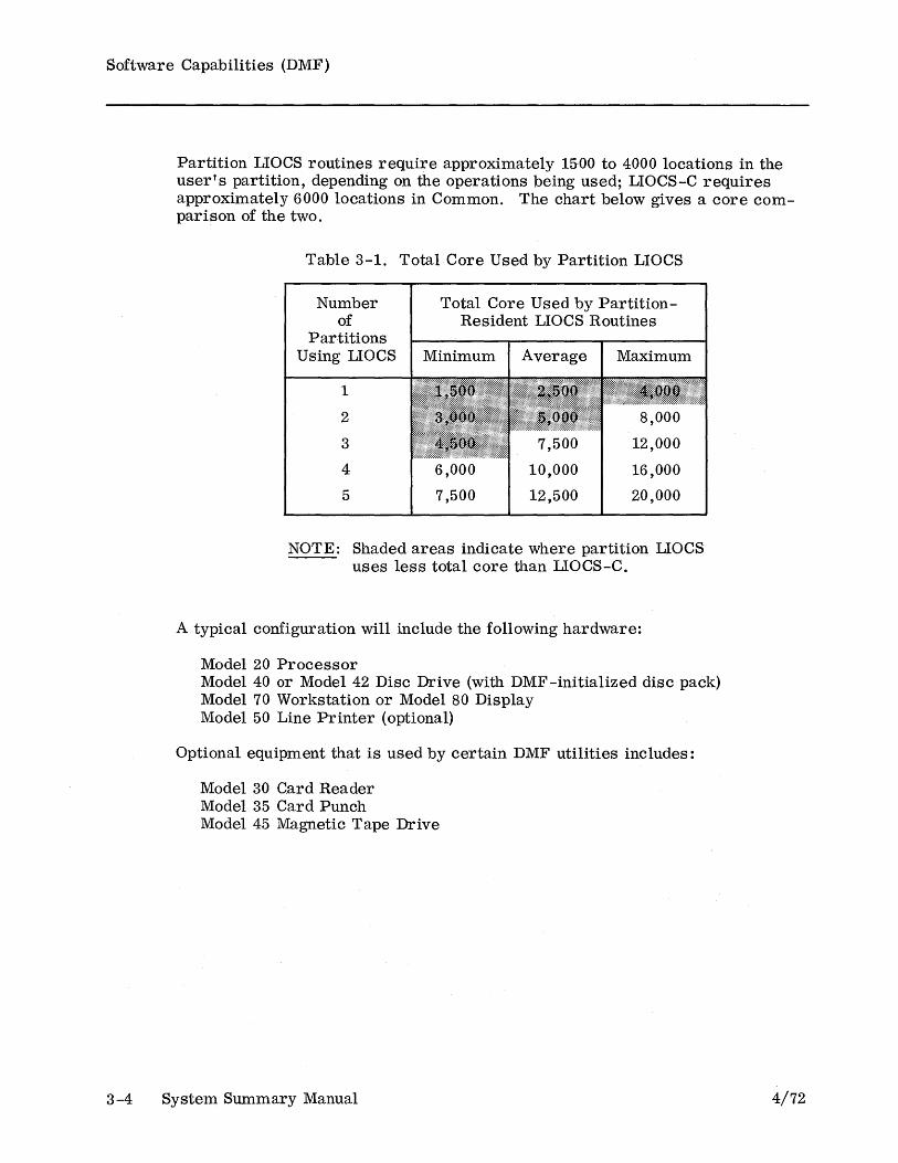
Partition LIOCS routines require approximately 15-00 to 4000 locations in the user's partition, depending on the operations being used; LIOCS-C requires approximately 6000 locations in Common. The chart below gives a core comparison of the two.
Table 3-1. Total Core Used by Partition LIOCS
Number of
Partitions Using LIOCS
1
2
3
4
5
Total Core Used by PartitionResident LIOCS Routines
6,000
7,500
10,000
12,500
16,000
20,000
NOTE: Shaded areas indicate where partition LIOCS uses less total core than LIOCS-C.
A typical configuration will include the following hardware:
Model 20 Processor Model 40 or Model 42 Disc Drive (with DMF -initialized disc pack) Model 70 Workstation or Model 80 Display Model 50 Line Printer (optional)
Optional equipment that is used by certain DMF utilities includes:
Model 30 Card Reader Model 35 Card Punch Model 45 Magnetic Tape Drive
System Summary Manual 4/72

Software Capabilities (DMF)
ASSEMBLER II
Assembler II has all the capabilities of Assembler I (page 3-17) plus the following additions:
• Macro definition and expansion
• Conditional assembly
• Assembly-time variables, statements, and functions
• An extended set of instruction mnemonics
• Literals
• Relocatable object code
• A symbol cross-reference listing that gives "where set" and "where used"
• Assemble-and-execute capability
• Additional assembler control statements
• Disc storage of assembler work files, including the symbol table, allowing large program to be assembled that Assembler I will not handle.
Any program which can be assembled by Assembler I can be assembled by Assembler II without any changes.
Core and Configuration Requirements
4/72
Assembler II requires 9,000 locations of the user partition in which it is loaded and does not use Common. Assembler II is stored on disc and is run under the control of the Disc Management Facility (DMF). Source input may be in the form of a DMF file or it may be read through any input device. Object code and listings may be deposited in DMF files or may be routed to any output device.
No hardware other than that required by DMF is necessary.
System Summary Manual 3-5
Software Capabilities (DMF)
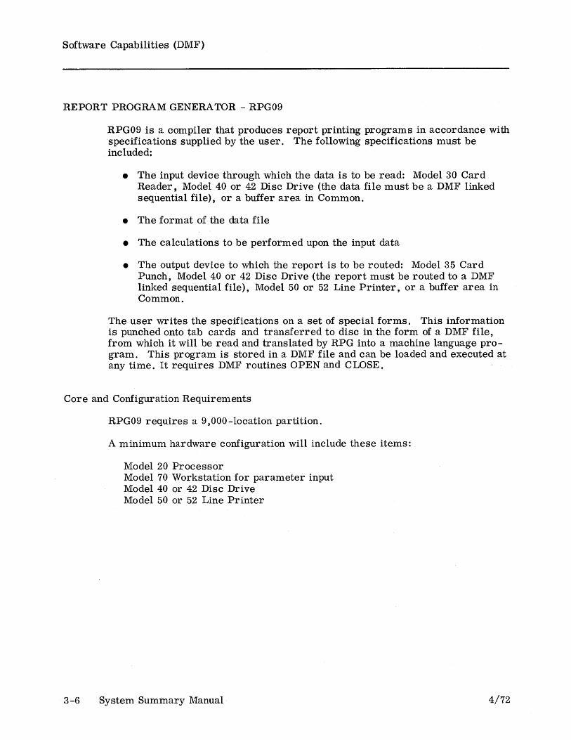
REPORT PROGRAM GENERATOR - RPG09
RPG09 is a compiler that produces report printing programs in accordance with specifications supplied by the user. The following specifications must be included:
• The input device through which the data is to be read: Model 30 Card Reader, Model 40 or 42 Disc Drive (the data file must be a DMF linked sequential file), or a buffer area in Common.
• The format of the data file
• The calculations to be performed upon the input data
• The output device to which the report is to be routed: Model 35 Card Punch, Model 40 or 42 Disc Drive (the report must be routed to a DMF linked sequential file), Model 50 or 52 Line Printer, or a buffer area in Common.
The user writes the specifications on a set of special forms. This information is punched onto tab cards and transferred to disc in the form of a DMF file, from which it will be read and translated by RPG into a machine language program. This program is stored in a DMF file and can be loaded and executed at any time. It requires DMF routines OPEN and CLOSE.
Core and Configuration Requirements
3-6
RPG09 requires a 9,000-location partition.
A minimum hardware configuration will include these items:
Model 20 Processor Model 70 Workstation for parameter input Model 40 or 42 Disc Drive Model 50 or 52 Line Printer
System Summary Manual 4/72

Software Capabilities (DMF)
REPORT PROGRAM GENERATOR - RPG10
This compiler is an expanded version of RPG09. Some of the additional capabilities are outlined below.
• Either a disc file or a card reader can be used for source input.
• The object program can be placed in a disc file or punched as an object deck.
• Multi-sector disc rec ords can contain up to 940 characters.
• In addition to the Hollerith 11-zone punch for negative numbers, the compiler recognizes the 12-zone punch for positive numbers and will enter both into the system properly. It will also generate a Hollerith negative number for punched card output.
• Logical AND/OR relationships are allowed in calculations.
• Contents of a field can be displayed on a workstation and modified from it.
• A "compile-and-go" option is available when the object program is written to a disc file.
• Split control fields (L1 - L9) are allowed.
RPG10 requires DMF routines R_OPEN and CLOSE.
Core and Configuration Requirements
4/72
RPG10 uses a minimum of 10,000 locations in partition.
A minimum configuration consists of:
Model 20 Processor Model 70 Workstation Model 40 or 42 Disc Drive Model 50 or 52 Line Printer
Recommended optional hardware includes:
Model 30 Card Reader for RPG source input or parameter input Model 35 Card Punch for punching the object program
System Summary Manual 3-7
Software Capabilities (DMF)
APPEND (DMF)
APPEND provides a basic library facility for Assembler I (Disc Version). The APPEND program reads the user's base source deck, retrieves specified modules from a disc library, merges these modules with the base deck, and puts the expanded source program on disc for input to Assembler I. The user directs APPEND (via a console device) to read his base deck from either disc or card reader. Parameters cannot be passed from the base deck to the library modules nor can one module call another module.
APPEND allows source data files and routines that are used in several programs to be stored on the disc. This capability promotes standardization for an installation and allows changes to be made easily. For example, an application file can be changed simply by changing one library module and re-assembling all programs that use it.
Core and Configuration Requirements
3-8
Core must be large enough to accommodate the DMF system and the LIOCS modules OPEN and CLOSE. A minimum configuration consists of the following hardware:
Model 20 Processor with a 9K partition Model 40 Disc Drive
Load Device:
Model 70 Workstation or Model 80 Display or Model 7102 Communications Terminal.
The following optional equipment can be added:
Model 30 Card Reader Additional Model 40 Disc Drives.
System Summary Manual 4/72

Software Capabilities (DMF)
CONVERSATIONAL TESTING PROGRAM-TESTER
The Conversational Testing Program (TESTER) makes it possible for the user to test and alter computer programs easily. TESTER provides facilities for program tracing, overlay tracing, core dumping, disc dumping, disc patching, and program modification. TESTER provides more testing functions and has a considerably more versatile load function than does EZTEST. TESTER may be used in a conversational manner from a workstation or CRT display or it may be used in a batch manner directly by the program being tested.
Though TESTER resides in Common, it is not coded in re-entrant fashion. Consequently, TESTER can be used by only one user partition at a time and that partition must have a workstation or CRT display and a line printer attached.
Core and Configuration Requirements
4/72
TESTER resides in Common and requires 5,000 locations (locations lOOOC -6000C). Because it operates under the control of the Disc Management Facility (DMF), TESTER also requires the first 600 locations of the user partition in which the program being tested is loaded. TESTER requires a Model 40 or 42 Disc Drive with a DMF pack, a Model 70 Workstation or a CRT display (device 0), and a Model 50 or 52 Line Printer (device 2). The workstation and line printer must be attached to the user partition in which the program to be tested is loaded.
System Summary Manual 3-9

Software Capabilities (DMF)
DMF DISC SORT
DMF Disc Sort is a utility program which sorts the records in a DMF linked sequential disc file into any specified sequence. Up to six sort keys may be used. The sorting sequence (ascending or descending) as well as the type of sort (character or signed numeric) may differ for each key.
DMF Disc Sort operates under the control of the Disc Management Facility (DMF).
Records may be blocked or unblocked. Since the maximum allowable record block size is 94 characters, the total length of the records within the block must not exceed this figure. In the case of unblocked records, the maximum allowable record size is 940 characters. The blocking factor of the output file need not be identical with that of the input file.
At execution time, sort control information may be read from a DMF linked sequential disc file or it may be entered through a card reader or other suitable input devic.e. Sort parameters, error messages, and miscellaneous control informa~ion are printed on a user -specified printing device.
Core and Configuration Requirements
3-10
DMF Disc Sort requires at least 9,000 locations of the user partition in which it is loaded. In the way of deVices, it requires a load deVice, a disc drive, and a printing device (line printer, workstation, or CRT display). On the disc drive must be mounted a DMF disc pack containing the file to be sorted, the file to which the sorted output is to be routed, and a work pool. If the sort control statements are not contained in a DMF disc file, then DMF Disc Sort requires an input device (card reader, workstation, CRT display, or paper tape reader) through which the sort control statements will be entered. The device addresses of the input and printing devices are aSSigned by the user through the use of the DMF ASSIGN control statement.
System Summary Manual 4/72

Software Capabilities (DMF)
DMF FILE COpy
DMF File Copy is a utility program which copies files from one device to another. DMF File Copy operates under the control of the Disc Management Facility (DMF).
The file being copied may contain fixed-length or variable-length records, blocked or unblocked, and may come from any of the following devices:
Model 30 Card Reader
Model 40 or 42 Disc Drive (either a physical sequential file or a DMF linked sequential file)
Model 45 Magnetic Tape Drive
Model 60 Paper Tape Reader
Model 70 Workstation
Model 80 Display
The file being produced may contain fixed-length or variable-length records, blocked or unblocked, and may be routed to any of the following devices:
Model 35 Card Punch
Model 40 or 42 Disc Drive (either a physical sequential file or a DMF linked sequential file)
Model 50 or 52 Line Printer
Model 65 Paper Tape Punch
Model 70 Workstation
Model 80 Display
The blocking factor and record length of the file being produced need not be identical with that of the input file. -
The user defines the input and output files by supplying a series of parameters. This is done in a conversational manner using the workstation or CRT display. If the output device is specified as being something other than a line printer, the user may request that an auxiliary listing be produced.
Core and Configuration Requirements
4/72
DMF File Copy requires at least 7,000 locations of the user partition in which it is loaded. In addition, it requires a workstation or CRT display (device 0) and a disc drive. On the disc drive must be mounted a DMF pack with the programs FILEC and FILEC_filed in SYSPOL.
System Summary Manual 3-11
Software Capabilities (DMF)
DMF MULTI-PARTITION LOADER (DMF MPL)
The DMF Multi-Partition Loader (DMF MPL) loads object programs into user partitions 1 - 19 through user partition 0, thus providing a convenient way of loading programs into user partitions which have no input/output peripheral devices attached to them (such as an SCA partition). DMF MPL operates under the control of the Disc Management Facility (DMF). The programs to be loaded may come from any input device, including disc (DMF linked sequential disc files).
With DMF MPL, the user may
• load a single program into anyone user partition
• load several programs, each into a separate user partition
• load a single program into several different user partitions
• any combination of the above.
The parameters for loading the programs are contained in a file called the procedure library. The procedure library may come from cards, a DMF linked sequential disc file, punched tape, magnetic tape, or it may be typed in through a workstation. In any case, the library contains a pair of card images for every program which is to be loaded. The first card image in each pair specifies into what partition(s) the program is to be loaded; the second specifies from what device the program is to be read.
Core and Configuration Requirements
3-12
DMF MPL uses the protected area of Common (locations 0000C-0299C) and the Inter-Partition Mailbox (locations 0580C-0999C). During execution, DMF MPL is loaded into locations 1000-5238 of user partition O.
System Summary Manual 4/72
Software Capabilities (DMF)
LANGUAGE EDITOR UTILITY (LEU)
The Language Editor Utility (LEU) is a utility program which makes it possible for the user to edit DMF files from a workstation, a CRT display or other laC input device. LEU operates under the control of the Disc Management Facility (DMF).
Since LEU is distributed in source form, the user may assemble (using Assembler II) his own tailored version of LEU. By supplying assembly-time variables, the user can specify which input and output devices are to be used for editing, and may supply alternate mnemonics for the various editing commands.
Once a tailored version of LEU has been assembled and stored on the DMF pack, the user may use it to edit other DMF files. It is assumed that the files to be edited contain a series of source language statements (such as Assembler II or RPG) stored one statement per sector. With LEU, the user may delete a specific statement from a file, delete a series of statements from a file, add a new statement anywhere within a file, or modify the contents of any statement in a file.
Core and Configuration Requirements
4/72
During execution, LEU requires 5,000 locations of the user partition in which it is loaded.
This utility program requires a Model 70 Workstation, Model 80 Display, or other laC input device.
System Summary Manual 3-13

Software Capabilities (DMF)
TEXT EDITOR
The Text Editor is a utility program that makes it possible for the user to edit DMF files from a Model 70 Workstation or a Model 80 Display. The files to be edited are assumed to contain 80-character'source language statements, one statement per sector, and must be DMF type S files (doubly linked sequential format).l
The Text Editor can perform the following editing functions:
• Add one or a series of new source statements anywhere in the file.
• Locate a source statement by its line number, its location (in lines) from the current source statement, its label, or by-a character string within the statement.
• Alter the contents of any existing source statement.
• Replace any source statement with a new source statement.
• Delete one or a series of source statements from the file.
• Change a character string to another character string in one or more source statements, where the replacement character string can be the same size as, or shorter or longer than, the original character string.
• Print a series of source statements, or the entire file, on a line printer or on the workstation or display.
• Repeat the previous Text Editor function one or more times.
• Perform source statement insertion, deletion, or replacement, stopping when a speCified character string is found.
• Add one or a series of source statements that are extracted from specified locations in either the file being edited or any other DMF file, linked sequential or doubly linked.
In addition, editing commands stored in a separate disc file may be executed during an editing session. With the Text Editor,- the user may also create a new source statement file. The Text Editor uses the control keys on the workstation or display to perform special functions such as tabbing to a specified column within the current source statement. A function to insert an identification field and sequence a file of source statements is also available.
lIn a linked sequential file, the last six characters of each record contain the address of the next logical record. In a doubly linked sequential file, each record contains a pointer to the preceeding logical record as well.
3-14 System Summary Manual 4/72

Software Capabilities (DMF)
The Text Editor can be used for source statement editing of any computer language, including System Ten Assembler and RPG. This allows the System Ten user who has access to another computer to use the Text Editor for editing his source programs (such as COBOL, FORTRAN, PL/l, etc.) which would then be transferred (via cards, magnetic tape, or communication lines) to the other computer for compiling and executing.
Core and Configuration Requirements
4/72
The Text Editor requires 9,000 locations of the user partition in which it is used. It runs under the control of the Disc Management Facility (DMF). A Model 70 Workstation or Model 80 Display is required for input and output, and a Model,50 or Model 52 Line Printer can be used for printing the contents of a file.
System Summary Manual 3-15

Software Capabilities (DMF)
COMPATIBLE PROGRAMS
Other software programs that can be used with DMF are described with the basic software programs.
ProgTam
Assembler I
Code Translation (COTRAN)
Conver sational Testing Program (EZTEST)
3 -16 System Summary Manual
3-17
3-20
3-21
4/72

Software Capabilities (Basic/DMF)
ASSEMBLER I
Assembler I provides a machine-oriented, symbolic programming language which facilitates the writing of programs to be executed on a System Ten computer. The symbolic instruction set contains one instruction for each machine instruction, a group of instructions for controlling the assembly process (ORG, COMMON, NORMAL, END, EXEC), and a group of instructions for controlling the format of the assembly listing (TITLE, SPACE, EJECT). In addition, there is a memory definition instruction whereby the programmer can create input and output areas, work areas, and constants. Comment statements may be freely interspersed among the symbolic instructions.
Through the use of statement labels, the programmer may assign alphanumeric names to locations in memory. The programmer may then use the names (either by themselves or in conjunction with numeric values) to refer to memory locations. The programmer may also use an asterisk in conjunction with a numeric value to refer to memory locations relative to the location of the instruction containing the asterisk expression.
Assembler I includes a feature whereby the programmer may signify certain instructions as being "debug" instructions. During assembly, the "debug" instructions are either assembled like any other instruction or they are ignored (depending upon an assembly parameter).
Assembler I may be used in card form or it may be stored on disc and run under the control of the Disc Management Facility (DMF). DMF Assembler I has an optional cross-reference listing facility.
Core and Configuration Requirements
4/72
Assembler I requires at least 9,000 locations of the user partition in which it is loaded and does not ordinarily use Common. However, through the use of an assembly parameter, the programmer may permit the assembler to use a portion of Common for constructing the label table.
A minimum configuration consists of Model 30 Card Reader, Model 35 Card Punch, Model 50 or 52 Line Printer and a Model 20 Processor.
System Summary Manual 3-17
Software Capabilities (Basic)
ABSOLUTE OBJECT CARD LOADER
The Absolute Object Card Loader is a utility program that loads object programs into a user partition through a Model 30 Card Reader. If loading is completed successfully, control passes to the user's object program.
The loader followed by the deck(s) to be loaded must be placed in the card reader input hopper. The user then enters a "bootstrap" instruction through the load device.
The loader determines which partition it is loading into and stores the partition number in locations 0047 and 0048 of the user partition. The loader also checks the object deck for sequence errors. If one is detected, an error message is printed on a user-spectfied device and loading is terminated.
The loader can be used for loading programs that contain a sequence of overlays and can also load a series of programs where each is a separate job.
Clear Core Prologues
3-18
There are two prologue programs that change the contents of the user partition to spaces or any other user-specified character. The prologue is followed by the loader and the deck to be loaded.
The Clear Core Prologue changes the contents of the user partition from location 300 through the end of the partition. The Selective Clear Core Prologue changes the contents of a user-specified areas of the partition.
System Summary Manual 4/72

Software Capabilities (Basic)
BRANCH TRACE
Branch Trace is a utility program which traces the flow of program 'execution by maintaining a record of the 12 most recent successful branches in the user's program.
Typically, Branch Trace is assembled and loaded with the program which is to be traced. However, Branch Trace may reside permanently either in a user partition or Common.
When the user's program is finished being executed, the user may dump a buffer area to see the 12 addresses which were most recently branched to before the program terminated.
Core and Configuration Requirements
4/72
Branch Trace is written in Assembler I symbolic language. During execution, Branch Trace occupies 500 locations of memory.
System Summary Manual 3-19
Software Capabilities (Basic/DMF)
CODE TRANSLATION (COTRAN)
Code Translation (COTRAN) is a utility program which generates code translation programs in accordance with specifications supplied by the user. The programs thus produced are in Assembler r source language. To use a code translating program produced by COTRAN, the programmer assembles the code translating program with his main program. At the appropriate points, the main program contains branches to the code translating program.
Core and Configuration Requirements
3-20
COTRAN requires 9,000 locations of the user partition in which it is used. In addition, it requires a card reader (device 0), a printing device (device 2), and a card punch (device 4). The user may alter the device address assignments by changing the contents of three columns in the first card of the COTRAN deck.
System Summary Manual 4/72

Software Capabilities (Basic/DMF)
CONVERSATIONAL TESTING PROGRAM - EZTEST
The Conversational Testing Program (EZTEST) makes it possible for the user to test and alter computer programs easily. EZTEST provides facilities for program tracing, core dumping, and program modification. EZTEST may be used in a conversational manner from a workstation or CRT display or it may be used in a batch manner directly by the program being tested.
Though EZTEST resides in Common, it is not coded in re-entrant fashion. Consequently, EZTEST can be used by only one user partition at a time.
Core and Configuration Requirements
4/72
EZTEST resides in Common and requires 9,000 locations (locations 1000C-9999C). In the conversational mode, EZTEST requires a Model 70 Workstation or a CRT display (device 0) and a Model 50 or 52 Line Printer (device 2). In the batch mode, the workstation is not required.
System Summary Manual 3-21
Software Capabilities (Basic)
DISC SORT
Disc Sort is a utility program that sorts the records in a physical sequential disc file into a user-specified sequence. Up to six sort keys (record fields) may be used. The sorting sequence (ascending or descending) as well as the type of sort (character or signed numeric) may differ for each key. This Disc Sort is not used for sorting DMF files.
Records may be blocked or unblocked. The maximum allowable block size (or record size in the case of unblocked records) is 100 characters. The blocking factor of the output file need not be identical with that of the input file.
Core and Configuration Requirements
3-22
Disc Sort requires at least 9,000 locations of the user partition in which it is loaded. In addition, it requires a card reader, a load device (the card reader may also serve as the load device), a printing device (device 2), and at least one disc drive.
The user enters parameters through the card reader. The sort parameters, error messages, and miscellaneous control information are printed on the printing device.
System Summary Manual 4/72

Software Capabilities (Basic)
FILE COpy
File Copy is a utility progTam which copies files from one device to another.
The file being copied may contain fixed-length or variable-length records, blocked or unblocked, and may come from any of the following devices.
Model 30 Card Reader
Model 40 or 42 Disc Drive (either a physical sequential file or a DMF linked sequential file)
Model 45 Magnetic Tape Drive
Model 60 Paper Tape Reader
Model 70 Workstation
Model 80 Display
The file being produced may contain fixed-length or variable-length records, blocked or unblocked, and may be routed to any of the following devices.
Model 35 Card Punch
Model 40 or 42 Disc Drive (physical sequential file only)
Model 45 Magnetic Tape Dr ive
Model 50 or 52 Line Pr inter
Model 65 Paper Tape Punch
Model 70 Workstation
Model 80 Display
The blocking factor and record length of the file being produced need not be identical with that of the input file. -
The user defines the input and output files by supplying a series of parameters, This is done either by reading a deck of parameter cards through the card reader or by entering the card images through the workstation. If the output device is specified as being something other than a line printer, the user may request that an auxiliary listing be produced.
Core and Configuration Requirements
4/72
File Copy requires at least 6,000 locations of the user partition in which it is loaded. In addition, it requires a card reader (device 0) or a workstation (device 0) and a card reader (device 1). -
System Summary Manual 3-23

Software Capabilities (Basic)
INTERPRETIVE DUMP
Interpretive Dump is a utility program which displays the contents of selected areas of main memory. Each group of ten locations in the selected areas of memory is displayed in two forms .
• As data (displayed as ten alphanumeric characters)
• As a machine instruction, displayed in Assembler I symbolic instruction format
The user enters parameters through the card reader. Each parameter card contains those parameters necessary for displaying one segment of the user partition or Common.
The Absolute Object Card Loader followed by the Interpretive Dump program followed by the parameter cards must be placed in the card reader's input hopper. The user then enters a "bootstrap" instruction through the load device.
Core and Configuration Requirements
3-24
Interpretive Dump resides in locations 0300C-0999C of Common and uses Index Register 1 of the user partition which is being dumped. In addition, it requires a card reader, a load device (the card reader may also serve as the load device), and a printing device.
System Summary Manual 4/72
Software Capabilities (Basic)
MULTI-PARTITION LOADER (MPL)
The Multi-Partition Loader (MPL) loads object programs into user partitions 1-19 through user partition 0, thus providing a convenient way of loading programs into user partitions which have no input/output peripheral devices attached to them (such as an SCA partition),
With MPL, the user may
• load a single program into anyone user partition,
• load several programs, each into a separate user partition,
• load a single program into several different user partitions, or
• any combination of the above.
The Absolute Object Card Loader, followed by MPL, followed by the decks to be loaded must be placed in the card reader's input hopper. Each deck to ge loaded must be preceded by an MPL parameter card. The user then enters a "bootstrap" instruction through the load device.
MPL uses the protected area of Common (locations 0000C-0299C) and the Inter-Partition Mailbox (locations 0580C-0999C).
Core and Configuration Requirements
4/72
MPL uses three logical devices: one for MPL parameter card input, one for reading the loaders and the user's object decks, and one for printing messages to the computer operator. By altering the contents of three columns in the MPL deck, the user may specify any device addresses for these logical devices, Unless the user does this, however, MPL assumes that all input is entered through device 1 (presumably a card reader) and that all messages to the computer operator are to be printed on device 0 (presumably a workstation),
System Summary Manual 3-25
Software Capabilities (Basic)
STAND-ALONE DUMP
Stand-Alone Dump is a utility program which displays the contents of selected areas of main memory. Each group of ten locations in the selected areas is displayed as ten alphanumeric data characters.
The user enters parameters through the card reader. Each card contains the parameters necessary for displaying one segment of the user partition or Common.
The Absolute Object Card Loader followed by the Stand-Alone Dump followed by the parameter cards must be placed in the card reader's input hopper. The user then enters a "bootstrap" instruction through the load device.
Core and Configuration Requirements
3-26
Stand-Alone Dump resides in locations 0300C-0999C of Common and uses Index Register 1 of the user partition which is being dumped. In addition, it requires a card reader, a load device (the card reader may also serve as the load device), and a printing device.
System Summary Manual 4/72
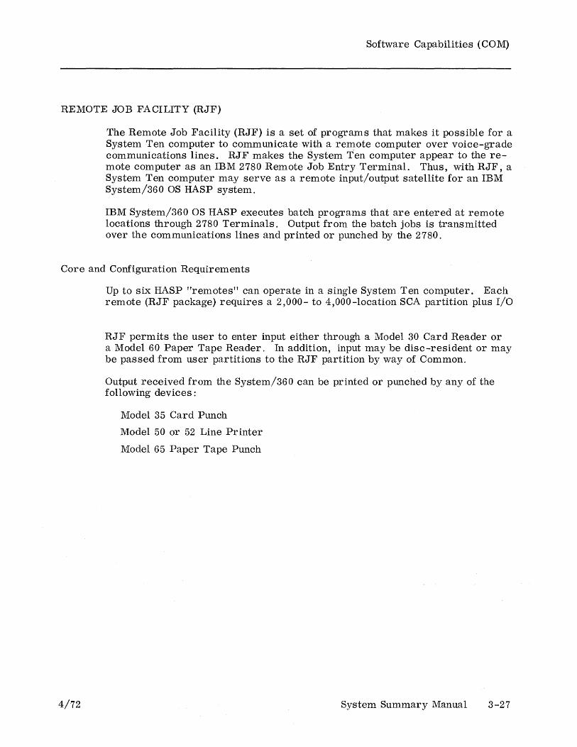
Software Capabilities (COM)
REMOTE JOB FACILITY (RJF)
The Remote Job Facility (RJF) is a set of programs that makes it possible for a System Ten computer to communicate with a remote computer over voice-grade communications lines. RJF makes the System T-en computer appear to the remote computer as an IBM 2780 Remote Job Entry Terminal. Thus, with RJF, a System Ten computer may serve as a remote input/output satellite for an IBM System/360 OS HASP system.
IBM System/360 OS HASP executes batch programs that are entered at remote locations through 2780 Terminals. Output from the batch jobs is transmitted over the communications lines and printed or punched by the 2780.
Core and Configuration Requirements
4/72
Up to six HASP "remotes" can operate in a single System Ten computer. Each remote (RJF package) requires a 2,000- to 4,000-location SCA partition plus I/O
RJF permits the user to enter input either through a Model 30 Card Reader or a Model 60 Paper Tape Reader. In addition, input may be disc-resident or may be passed from user partitions to the RJF partition by way of Common.
Output received from the System/360 can be printed or punched by any of the follOWing devices:
Model 35 Card Punch
Model 50 or 52 Line Pr inter
Model 65 Paper Tape Punch
System Summary Manual 3-27
Software Capabilities (COM)
REMOTE JOB FACILITY (RJF) - DISC VERSION
A disc version of the RJF package allows input to the data transmission system from DMF files resident on disc. The user can create files and transmit them to a HASP system without preparing an intermediate card deck or paper tape. Punch files received from the HASP system may be spooled to the disc.
Core and Configuration Requirements
3-28
The disc version requires a 2,000-location SCA partition, a 9,000-location I/O partition, and 1,000 locations in Common.
System Summary Manual 4/72
Software Capabilities (COM)
SYNCHRONOUS COMMUNICATION ACCESS METHOD (SCAM)
The Synchronous Communication Access Method (SCAM) is a set of 16 programs which are designed for controlling the Synchronous Communications Adapter (SCA) input/output channel of a System Ten computer. The programs are distributed in source language form. From the 16 programs, the user chooses 5 or 6 which specifically relate to his needs. The chosen programs are then assembled together into one object program and the object program is loaded into the SCA partition. The object program is referred to as an SCA Module.
The SCA Module interacts with the user's application programs by way of Common.
An SCA Module may be tailored to use either dedicated (private or leased) lines or the switched (DDD) telephone network. With dedicated lines, the SCA Module can function either as part of a point-to-point configuration or as part of a centralized, multi-point configuration.
An SCA Module can communicate with most computers equipped with a synchronous communications channel and that transmit and receive ASCII data according to the rules of binary synchronous communications, or with certain synchronous communications terminals.
An example of the latter is the 4310 series of the Singer 4300 Magnetic Data Recording System. The 4310 is a keyboard-to-magnetic tape device. However, it can have a Model 50 or 52 Line Printer attached to it. Thus, communication between the SCA Module and a 4310 could be in any of the following forms: SCA to magnetic tape, magnetic tape to SCA, or SeA to line printer.
Core and Configuration Requirements
4/72
These requirements will vary with the user's needs; a load device and the SCA are mandatory.
System Summary Manual 3-29
Software Capabilities (Mise)
MODULAR BUSINESS MANAGEMENT SYSTEM (MBMS)
The Modular Business Management System (MBMS) is a set of programs that provides many business processing capabilities.
• Sales order entry
• Invoicing
• Accounts receivable processing
• Accounts payable processing
• Inventory control
• Sales analysis reporting
• General ledger processing
• Payroll processing
MBMS is designed in a modular fashion so that the user may purchase or lease only those modules that he actually needs. In addition, the modules can be adapted easily and economically to meet the needs of each individual installation.
During execution, the system prints messages on a workstation. The operator responds to each message by entering the requested data.
Core and Configuration Requirements
3-30
MBMS is designed to operate in a minimum configuration containing a 10,000-location Common partition, one 10,000-location user partition, one disc drive, and one workstation. However, a line printer is recommended to print the various reports generated by MBMS as speedily and economically as possible. For each workstation which is added to the system, an additional 10,000-location user partition is required.
System Summary Manual 4/72

APPENDIX A: REFERENCE DOCUMENTS
Hardware Manuals
4/72
Model 20 Processor
Model 30 Card Reader
Model 35 Card Punch
Model 40 Disc Drive
Model 42 Disc Drive
Model 45 Magnetic Tape Drive
Model 50 Line Printer
Model 52 Line Pr inter
Model 60 Paper Taper Reader
Model 65 Paper Tape Punch
Model 70 Workstation
Model 80 Display
Model 100 Job Information Station
Model 105 Attendance Station
Model 191 Line Switching Unit
Model 800 Individual Store and Forward Unit
Model 850 ASTA: Asynchronous to Synchronous Terminal Adapter
Model 900 MDTS Data Terminal
ACA: Asynchronous Communications Adapter
A TA: Asynchronous Terminal Adapter
Digital Clock
External Clock Interface
SCA: Synchronous Communications Adapter
Reference Operating Manual No. Manual No.
40-020R
40-047 40-021
40-048 40-022
40-049 40-023
40-049 40-332
40-050 40-024
40-051 40-025
40-297 40-333
40-052 40-026
40-208 40-207
40-053 40-027
40-209 40-210
40-229
40-075
40-271
40-118
40-203
40-202
40-324
40-325
40-073
40-272
40-071
System Summary Manual A-I
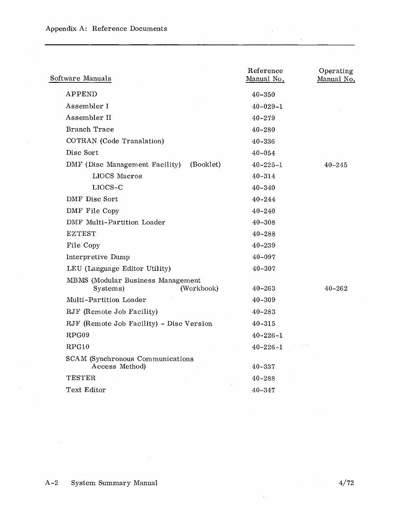
Appendix A: Reference Documents
Software Manuals
A-2
APPEND
Assembler I
Assembler II
Branch Trace
COTRAN (Code Translation)
Disc Sort
DMF (Disc Management Facility) (Booklet)
LIOCS Macros
LIOCS-C
DMF Disc Sort
DMF File Copy
DMF Multi-Partition Loader
EZTEST
File Copy
Interpretive Dump
LEU (Language" Editor Utility)
MBMS (Modular Business Management Systems) (Workbook)
Multi-Partition Loader
RJF (Remote Job Facility)
RJF (Remote Job Facility) - Disc Version
RPG09
RPG10
SCAM (Synchronous Communications Access Method)
TESTER
Text Editor
System Summary Manual
Reference Manual No.
40-350
40-029-1
40-279
40-280
40-336
40-054
40-225-1
40-314
40-340
40-244
40-240
40-308
40-288
40-239
40-097
40-307
40-263
40-309
40-283
40-315
40-226-1
40-226-1
40-337
40-288
40-347
Operating Manual No.
40-245
40-262
4/72
w a: w ::t ::t (J
« .... w C
SYSTEM SUMMARY MANUAL Publication No. 40-329
We produce manuals for you, and we want you to find them useful and informative. That's our job.
So we're asking you to help us furnish you with the best possible publications. Please take a few minutes to answer the following questions. Add any comments you wish. If you desire a reply to any question, be sure to include your name and address.
Thank you.
. ".
• Does this manual meet your needs? Yes 0 If not, what additional information would be of help to you?
• Can you find what you're looking for quickly and easily? How can the organization be improved?
• Is the material easy to read and to understand? Are there enough illustrations to support the text?
Yes 0
Yes 0 Yes 0
No 0
No 0
No 0 No 0
Comments ________________________________________________________________________ __
• Did you find any errors or ambiguities in the manual? Yes 0 No 0 If yes, please cite page, line, and/or figure number with your comments.
• Other comments.
• What is your relationship to the product described? o Oper~tor. o Programmer. o Other (please specify)
SINGER BUSINESS MACHINES
STAPLE
FOLD BACK
BUSINESS REPLY MAIL No postage stamp necessary if mailed in the United States
POSTAGE WILL BE PAID BY
SINGER BUSINESS MACHINES 2350 Washington Ave. San Leandro, California 94577
Attn: Customer Technical Publications,
Department 753
FOLD BACK
STAPLE
FIRST CLASS
PERM IT No. 320 San Leandro, Calif.

SINGE,R BUSI.NE.SS MAcHINES
Publication No .. 40 ;,..329