Embed Size (px)
Citation preview
1
Slope stabilization solutions along railway platforms – Case study:
Slope stabilization at Linha do Oeste
Joel Lázaro Lucas
October 2016
Advised by Prof. Alexandre da Luz Pinto
Abstract:
Railway transportation is one of the most used methods for transference of passengers and economical goods. The
railway layout design is characterized by an extreme lack of flexibility, often leading to the intersection of sensible
areas from the geotechnical point of view. This can lead to the occurrence of soil movements that can represent an
imminent danger to passenger and goods and threaten the normal operation of the railway infrastructures.
The present work arises from the need to stabilize two slopes at “Linha do Oeste” railway line, near Mafra-Gare
station and Sapataria tunnel. Several slope stabilization solutions were executed, including retaining and drainage
structures, while taking into account the specific constraints of this particular context: on-site accessibility,
geological-geotechnical conditions and the impossibility of interrupting the railway service during long time
periods.
This work aims to make a compilation of knowledge on the main causal factors of slope instability, the main
solutions available and the major difficulties in their implementation. Therefore it is presented a case study of the
implementation of two retaining walls near “Linha do Oeste” railway line. Based on the information collected on
the field and the monitoring of the construction works, a comparative analysis of the instrumentation and a report
describing the work’s evolution were made and are presented in this document.
It was also carried out a numerical modeling of one of the retaining structures, using the finite element software
Plaxis 2D, in order to assess the quality of the results compared to the on-site monitoring.
The results showed consistency in the obtained displacements and allowed to conclude that the works of
stabilization contributed to the improvement of the overall slope stability.
Keywords: Slope Stability; Railway Line; Micropiles; Retaining Walls; Geotechnical Model
1. Introduction
In the present paper are described and presented two different slope stabilization solutions that were implemented
at “Linha do Oeste” railway line. The first solution, therefore referred as M1, is located at the right side slope
between the 33,480 and the 33,800 kilometer points, near the Mafra-Gare train station (Figure 1). The second
solution, therefore referred as M2, is located between the 44,500 and the 44,650 kilometer points, at the right side,
just before the Sapataria tunnel (Figure 2). Both interventions are located in the municipality of Mafra, Lisbon
district.
In these two slopes were observed movements of shallow materials (Bromhead, 1992). The instabilities occurred
as a result of heavy rainfall phenomes that happen in the surrounding areas during the hydrological year of 2009.

2
The intervention M1, has a linear development of 120 meters and is materialized by a retaining wall and a
reshaping of the slope geometry by decreasing the inclination and with the inclusion of intermediate horizontal
berms.
Figure 1 – Slope of Mafra-Gare before the implementation of M1 (JetSJ, 2011a)
The intervention M2 has a linear development of 114 meters, on the left side of the tracks, and is materialized by
a retaining wall made of precast concrete blocks, executed at the base and at the top of the slope (Patrício &
Teixeira, R, 2006).). As seen in Figure 2 the accessibilities to the site were very difficult and the space for the
stabilization works was much reduced, being the main reason for using a precast solution.
Figure 2 – Slope near the Sapataria tunnel, before the implementation of M2 (JetSJ, 2011a)
The main objective with both solutions was to stabilize the existing slopes without interfering with the train safe
circulation.
2. Constraints
2.1. Geological, Geotechnical and Hydrological
Regarding the Mafra-Gare slope, the solution design was supported by a geological-geotechnical model
constructed from the results of a site investigation campaign that consisted on the execution of several Standard

3
Penetration Tests in two different boreholes. The results of this analysis are presented in Table 1 – Geotechnical
parameters for the Mafra-Gare slope (JetSJ, 2011b)
Table 1 – Geotechnical parameters for the Mafra-Gare slope (JetSJ, 2011b)
Geotechnical Zones γ Φ c’ E’
[kN/m3] [º] [kPa] [MPa]
ZG1 – Landfill 18 a 19 25 - 5
ZG2 – Claystone 19 a 20 28 10 11
ZG3 – Very Stiff Marl 20 a 21 28 20 18
ZG4 – Stiff Marl 20 a 22 28 30 25
ZG5 – Limestone 22 a 24 32 40 20000
For the Sapataria slope the only support material considered was the Geological Map and the site slope observation,
allowing to estimate the values presented in Table 2.
Table 2 - Geotechnical parameters for the Sapataria slope (JetSJ, 2011b)
Geotechnical Zones γ ϕ c’ E’
[kN/ m3] [º] [kPa] [MPa]
Freixial Layer 19 32 15 25
2.2. Neighborhood conditions
Both interventions were very conditioned by neighborhood restrictions. The M1 slope is delimited by a municipal
road at the top and a railway at the base. Concerning the M2 slope, besides the railway, the implementation is
located adjacently to a centenary tunnel. The neighborhood conditions were one of the major constraints to the
execution of the slope stabilization solutions and obviously influenced their design.
3. Adopted solutions
3.1. Wall M1
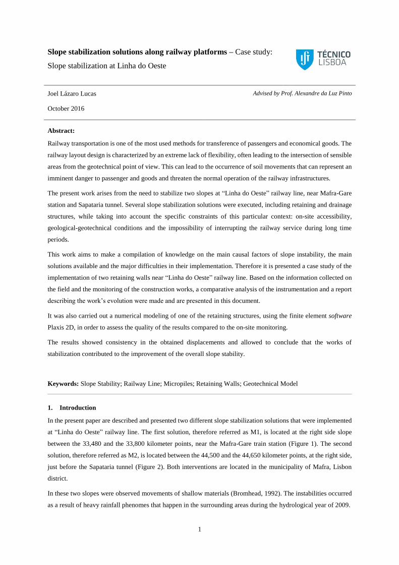
For the Mafra-Gare slope, the stabilization solution consisted in a retaining wall made with reinforced concrete
C30/77; XC4 and 0.30 meters thick. It was also prescribed that the slope’s final inclination should be reduced and
leading to the creation of an intermediate horizontal platform.
The wall is composed of HEB120 steel vertical beams, inserted in the soil prior to the wall execution and separated
by approximately 2.0 meters. The beams were placed in pairs on the wall’s primary panels. On the wall’s secondary
panels, a beam was placed on the symmetry axis in order to compensate the decompression of the soil due to the
excavation. The wall has a height of 3.0 meters and is also supported by a set of inclined micropiles (Type N-80
(API-5A) 114.3x9.0mm, 25mm steel bar on the interior). The micropiles were oriented in an angle of 30º with
the horizontal plane, far apart by 3.0 meters and executed in the front of the wall. It was possible to avoid the use
of ground permanent anchors or other definitive solution that would require a long-term follow-up (e.g.,
instrumentation and observation).The solidarization of the vertical elements and the inclined micropiles was made
by a reinforced concrete capping beam. As said before, the wall is composed by primary and secondary panels and
it was constructed from top to bottom alongside the excavation (Brito, 2002). Following the excavation, the
decreasing of the slope geometry, allowed the creation of stabilizing platforms, with 3.0 meters wide. The slope
4
drainage was also one of the main objectives. To avoid the saturation of the supported mass, drains were installed
and the slopes were covered with vegetation. In Figure 3 is showed a cross section of the proposed M1 solution.
Figure 3 - M1 proposed solution (JetSJ, 2011c)
3.2. Wall M2
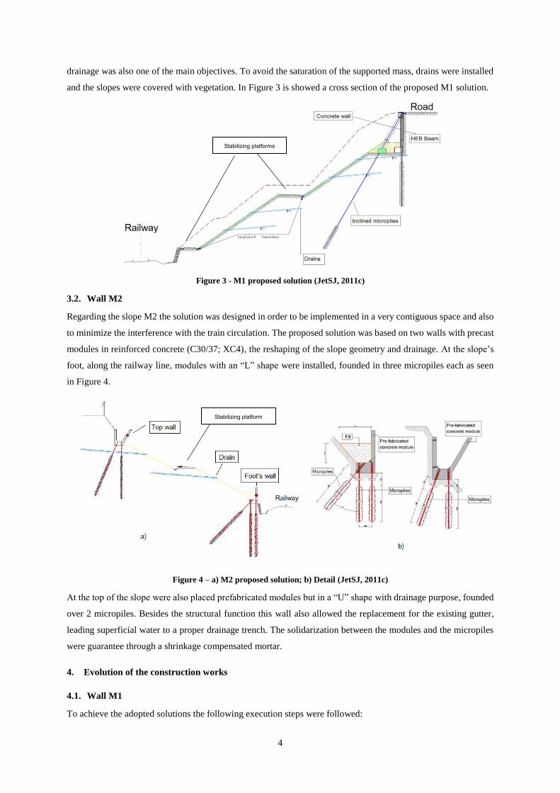
Regarding the slope M2 the solution was designed in order to be implemented in a very contiguous space and also
to minimize the interference with the train circulation. The proposed solution was based on two walls with precast
modules in reinforced concrete (C30/37; XC4), the reshaping of the slope geometry and drainage. At the slope’s
foot, along the railway line, modules with an “L” shape were installed, founded in three micropiles each as seen
in Figure 4.
Figure 4 – a) M2 proposed solution; b) Detail (JetSJ, 2011c)
At the top of the slope were also placed prefabricated modules but in a “U” shape with drainage purpose, founded
over 2 micropiles. Besides the structural function this wall also allowed the replacement for the existing gutter,
leading superficial water to a proper drainage trench. The solidarization between the modules and the micropiles
were guarantee through a shrinkage compensated mortar.
4. Evolution of the construction works
4.1. Wall M1
To achieve the adopted solutions the following execution steps were followed:
Stabilizing platforms
Stabilizing platform
5
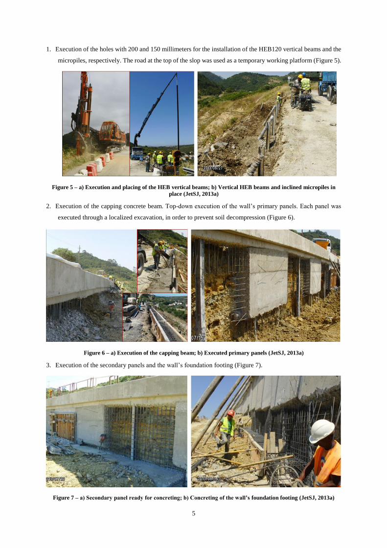
1. Execution of the holes with 200 and 150 millimeters for the installation of the HEB120 vertical beams and the
micropiles, respectively. The road at the top of the slop was used as a temporary working platform (Figure 5).
Figure 5 – a) Execution and placing of the HEB vertical beams; b) Vertical HEB beams and inclined micropiles in
place (JetSJ, 2013a)
2. Execution of the capping concrete beam. Top-down execution of the wall’s primary panels. Each panel was
executed through a localized excavation, in order to prevent soil decompression (Figure 6).
Figure 6 – a) Execution of the capping beam; b) Executed primary panels (JetSJ, 2013a)
3. Execution of the secondary panels and the wall’s foundation footing (Figure 7).
Figure 7 – a) Secondary panel ready for concreting; b) Concreting of the wall’s foundation footing (JetSJ, 2013a)

6
4. Concreting of the inclined micropiles protection. Reformulation of the slope’s geometry, execution of a
draining mask and application of the vegetation protection lining (Figure 8).
Figure 8 – Final works on the Mafra-Gare slope (JetSJ, 2013a)
4.2. Wall M2
Regarding the wall M2 the main steps adopted to build the solution were the following:
1. Implementation of a work platform at the top of the slope allowing the operation of the drilling equipment.
Execution of drilling holes for the top wall foundation micropiles. Implantation of the top precast modules
and solidarization with the micropiles Figure 9.
Figure 9 – a) Work platform; b) Execution of the micropiles and implantation of the precast modules (JetSJ, 2013a)
2. Reshaping of the slope and execution of an intermediate horizontal platform. Application of a drainage mask
protected by a geotextile at the slope face (Figure 10).
3. Execution of the temporary work platform at the base of the slope for the drilling equipment operation.
Placement and sealing of the bottom precast modules (Figure 10). Placement of a geo-mesh, installation of
drainage devices and projection of vegetation (Figure 11).

7
Figure 10 – a) Reshaping of the slope and execution of the drainage mask; b) Placement and sealing of the bottom
precast modules (JetSJ, 2013a)
Figure 11 – a) Placement of a geo-mesh b) Drainage device detail and projection of hydro seeding. (JetSJ, 2013a)
5. Monitoring and instrumentation
The planned instrumentation was defined from the analysis of the main constraints and the prevision of the factors
that could ultimately affect the intervention. Regarding the number of devices, it was initially planned the
placement of 5 and 11 topographic targets at the wall M1 and M2, respectively. It was also established the
placement of 2 inclinometers on wall M1 and 4 inclinometers on wall M2. The main objective of the proposed
instrumentation was to measure horizontal and vertical displacements in both walls, as well as horizontal
displacements inside the soil (JetSJ, 2011a). At Figure 12 is shown the location of the inclinometers.
Figure 12 - Planned instrumentation: a) Mafra-Gare slope; b) Sapataria slope (JetSJ, 2013a)

8
The analysis of the instrumentation results (JetSJ, 2013c) only contemplated the values measured by the IC-2
inclinometer. The results showed that the maximal horizontal displacement occur at a depth of 3.5 meter, during
the excavation, with a value of 8.3 mm. This value is far under the preconized alert and alarm values, 15 and 25
mm respectively.
6. Numeric modeling
The modeling of this case study focused on the ST9 section of the wall M1, corresponding to the 33,560 kilometer
point of “Linha do Oeste” railway line. The choice of this particular section was due to the fact that this was the
more conditioning from the excavation point of view. Also this was the section where the concrete wall was highest
and was located near the IC-2 inclinometer.
Table 3 – Mohr-Coulomb and geotechnical structural elements parameters used in the model (JetSJ, 2011b)
Structural Elements Micropiles HEB Beam Wall M1
Material type Elastic Elastic Elastic
EA [kN/m] 208400 357000 9900000
EI [kN2/m] 291 908 74250
w [kN/m/m] 0,6 0,6 4,5
ν 0,3 0,3 0,2
Mohr-Coulomb ZG1 (Landfill) ZG4 (Stiff Marl)
γunsat [kN/m3] 19 22
γsat [kN/m3] 21 24
Eref [kN/m2] 5000 25000
ν 0,3 0,3
Φ[º] 25 28
Ψ[º] - -
The main objective of the numeric modeling was to compare the horizontal displacement measured by the IC-2
inclinometer, during the excavation, with the displacements obtained through the model. For this purposes, it was
used Plaxis, a finite element software to make a finite element analysis (Caldeira, 2012). As input elements, the
geometry of the problem, the material parameters (Table 3) and the constructive phases were defined and were
obtained the displacements and stresses. The resulting deformed mesh is presented in Figure 13.
Figure 13 – Deformed model mesh
ZG1
ZG4
9
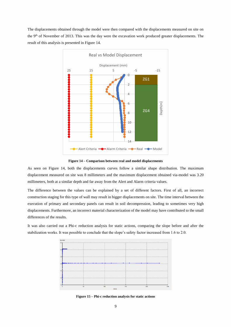
The displacements obtained through the model were then compared with the displacements measured on site on
the 9th of November of 2013. This was the day were the excavation work produced greater displacements. The
result of this analysis is presented in Figure 14.
Figure 14 – Comparison between real and model displacements
As seen on Figure 14, both the displacements curves follow a similar shape distribution. The maximum
displacement measured on site was 8 millimeters and the maximum displacement obtained via-model was 3.20
millimeters, both at a similar depth and far away from the Alert and Alarm criteria values.
The difference between the values can be explained by a set of different factors. First of all, an incorrect
construction staging for this type of wall may result in bigger displacements on site. The time interval between the
execution of primary and secondary panels can result in soil decompression, leading to sometimes very high
displacements. Furthermore, an incorrect material characterization of the model may have contributed to the small
differences of the results.
It was also carried out a Phi-c reduction analysis for static actions, comparing the slope before and after the
stabilization works. It was possible to conclude that the slope’s safety factor increased from 1.6 to 2.0.
Figure 15 – Phi-c reduction analysis for static actions
0
2
4
6
8
10
12
14
-15-551525
Dep
th(m
)
Displacement (mm)
Real vs Model Displacement
Alert Criteria Alarm Criteria Real Model
ZG1
ZG4

10
7. Main conclusions
The monitoring of the construction works has shown the importance of the specific conditions of this case, namely
the proximity to the railway line, the reduced space for the stabilization works, the difficult accessibilities, as well
as the heterogeneity of the geological and geotechnical scenario. Those factors have hampered the solution
designed and implementation.
It’s important to note the significance of on-site instrumentation and monitoring in complex geotechnical projects,
although the displacements measured in this case were far under the alert/alarm criteria.
Regarding the numeric model of the solution for the Mafra-Gare slope, the results showed that there are some
limitations using Plaxis software for modeling this type of walls. The 2D analysis lacked to contemplate the arch
effect created by temporary soil berms when executing the primary and secondary panels. On the other hand,
Plaxis is not the most suitable tool for slope stability analysis, especially when the soil interfaces are not horizontal.
A more thorough study would include a Limit Equilibrium analysis, using proper software for the effect.
The displacements shape obtain via-model are similar to the displacements measured on site, despite some
differences. These differences may be explained by a poor calibration of the soil/structural elements parameters
that did not simulate the real behavior and an improper construction staging, as well as the 2D modeling of a 3D
problem
As futures developments it is suggested, the construction of a finite element 3D model for both solutions (M1 and
M2), a limit equilibrium analysis for both slopes, a retro analysis with soil parameters variations and a study
inferring on possible alternate solutions taking into account the specific constraints of this case. These analysis
could support a possible optimization of the adopted solutions.
References
Brito, J. de. (2002). Muros de suporte de Betão Armado. Lisbon.
Bromhead, E. (1992). The Stability of Slopes.
Caldeira, L. (2012). Método dos Elementos Finitos. Folhas de apoio à disciplina de Modelação Avançada em
Geotecnia.
JetSJ. (2011a). Linha do Oeste: Troço Mafra Gare – Sapataria (Muro M1 PK 33+480 a Pk 33+680; Muro M2 PK
44+500 a Pk 44+650): Estabilização de Taludes - Memória Geral (in Portuguese).
JetSJ. (2011b). Linha do Oeste: Troço Mafra Gare – Sapataria (Muro M1 PK 33+480 a Pk 33+680; Muro M2 PK
44+500 a Pk 44+650): Estabilização de Taludes - Relatório geológico-geotécnico (in Portuguese).
JetSJ. (2011c). Linha do Oeste: Troço Mafra Gare – Sapataria (Muro M1 PK 33+480 a Pk 33+680; Muro M2 PK
44+500 a Pk 44+650): Estabilização de Taludes – Peças Desenhadas (in Portuguese).
JetSJ. (2013a). Linha do Oeste: Troço Mafra Gare – Sapataria (Muro M1 PK 33+480 a Pk 33+680; Muro M2 PK
44+500 a Pk 44+650): Estabilização de Taludes - Memória Fotográfica (in Portuguese).
JetSJ. (2013c). Linha do Oeste: Troço Mafra Gare – Sapataria (Muro M1 PK 33+480 a Pk 33+680; Muro M2 PK
44+500 a Pk 44+650): Estabilização de Taludes - Relatório de Instrumentação (in Portuguese).
Patrício, A., & Teixeira, R. (2006). Dimensionamento e Execução de Cortinas do Tipo Berlim.