Embed Size (px)
Citation preview
Slow Atomic Beams Manipulation
with Magnetic Videotapes
von
Habib Merimeche
Bonn 2004
Mathematisch-Naturwissenschaftlichen Fakultat
der
Rheinischen Friedrich-Wilhelms-Universitat Bonn


Angefertigt mit Genehmigung der Mathematisch-Naturwissenschaftlichen Fakultat
der Rheinischen Friedrich-Wilhelms-Universitat Bonn
1. Referent: Prof. Dr. Dieter Meschede2. Referent: Prof. Dr. Eberhard Klempt
Tag der Promotion: 4. Marz 2004

Abstract
Laser cooling methods provide the possibility to obtain very well collimated and slowatomic beams. These intense sources have attracted new interest in the manipulationof atomic trajectories. Atom optical schemes based on the optical dipole force are veryattractive, for example in atom lithography where atomic beams are focused by standingwave light fields, to create periodic nanostructures. However, in applications where morecomplex structures are desirable or decoherence due to spontaneous emission has to beavoided, magnetic atom optical components are more attractive.For example, flat and curved atomic mirrors with high reflectivity and low surface rough-ness can be built from periodically magnetized videotapes.First, with a collimated and polarized cesium atomic beam from a Zeeman-slower appara-tus, we have investigated the deflection of the atomic beam by a sinusoidally magnetizedvideotape with a period length of 30 µm. From these measurements we have determinedthe magnetic field strength at the surface to be 0.05 Tesla. The reflectivity has been foundto be consistent with 100%. The very large field gradients produced by the tape can beexploited to guide atoms on curved trajectories with small radii of curvature. With aradius of 9.5 cm we have obtained a maximum deflection angle of 25 which is limited bytechnical constraint.Second, we have built a setup based on a 2D-MOT for generating a slow atomic beam witha velocity of 20 m/s. After leaving the optical collimation and the optical polarizationstages, the atomic beam is reflected after one bounce onto the videotape up to angles aslarge as 7. We exploited the natural curvature of our videotape and we demonstrated thefocusing of the atomic beam after one and two bounces depending on the curvature of thevideotape. The focal length and the angles of deflection enable to deduce the local radii ofcurvature. We have confronted our results by testing the focusing of the videotape with ared laser and by performing a numerical simulation which prove the consistency with theatomic beam experiments.

Contents
1 Introduction 1
2 Reflective magnetic components 3
2.1 Stern-Gerlach force . . . . . . . . . . . . . . . . . . . . . . . . . . . . . . . . 32.2 Magnetic reflectors . . . . . . . . . . . . . . . . . . . . . . . . . . . . . . . . 4
2.2.1 Macroscopic permanent magnets . . . . . . . . . . . . . . . . . . . . 62.2.2 Microscopic magnetic materials . . . . . . . . . . . . . . . . . . . . . 72.2.3 Current-carrying wires . . . . . . . . . . . . . . . . . . . . . . . . . . 92.2.4 Natural crystals . . . . . . . . . . . . . . . . . . . . . . . . . . . . . 10
2.3 Imaging above a spherical mirror . . . . . . . . . . . . . . . . . . . . . . . . 12
3 Whispering gallery mirror for atom beams 15
3.1 Zeeman-slowed atomic beam . . . . . . . . . . . . . . . . . . . . . . . . . . 153.1.1 Principle of operation . . . . . . . . . . . . . . . . . . . . . . . . . . 153.1.2 Atomic beam apparatus . . . . . . . . . . . . . . . . . . . . . . . . . 163.1.3 Preparation of the atomic beam . . . . . . . . . . . . . . . . . . . . 17
3.2 Preparation of the reflector . . . . . . . . . . . . . . . . . . . . . . . . . . . 193.2.1 Magnetic recording . . . . . . . . . . . . . . . . . . . . . . . . . . . . 193.2.2 Mechanical construction . . . . . . . . . . . . . . . . . . . . . . . . . 213.2.3 Optical examination . . . . . . . . . . . . . . . . . . . . . . . . . . . 21
3.3 Atomic beam magnetometer for surface fields . . . . . . . . . . . . . . . . . 213.3.1 Experimental realization . . . . . . . . . . . . . . . . . . . . . . . . . 223.3.2 Results . . . . . . . . . . . . . . . . . . . . . . . . . . . . . . . . . . 23
3.4 Whispering gallery . . . . . . . . . . . . . . . . . . . . . . . . . . . . . . . . 243.4.1 Multiple bounces . . . . . . . . . . . . . . . . . . . . . . . . . . . . . 243.4.2 Experimental realization . . . . . . . . . . . . . . . . . . . . . . . . . 283.4.3 Results . . . . . . . . . . . . . . . . . . . . . . . . . . . . . . . . . . 28
4 A cold atomic beam from a 2D-MOT 33
4.1 Principles of operation . . . . . . . . . . . . . . . . . . . . . . . . . . . . . . 334.1.1 3D Magneto-optical trapping . . . . . . . . . . . . . . . . . . . . . . 334.1.2 Atomic beam generation from a 2D-MOT . . . . . . . . . . . . . . . 35
4.2 Experimental set-up . . . . . . . . . . . . . . . . . . . . . . . . . . . . . . . 374.2.1 Vacuum system . . . . . . . . . . . . . . . . . . . . . . . . . . . . . . 374.2.2 Laser systems . . . . . . . . . . . . . . . . . . . . . . . . . . . . . . . 40
4.3 2D-MOT . . . . . . . . . . . . . . . . . . . . . . . . . . . . . . . . . . . . . 404.3.1 Optical setup . . . . . . . . . . . . . . . . . . . . . . . . . . . . . . . 414.3.2 2D-MOT coils . . . . . . . . . . . . . . . . . . . . . . . . . . . . . . 414.3.3 Source of slow atoms . . . . . . . . . . . . . . . . . . . . . . . . . . . 42
4.4 Optical transverse collimation . . . . . . . . . . . . . . . . . . . . . . . . . . 43
I
II CONTENTS
4.4.1 Principle . . . . . . . . . . . . . . . . . . . . . . . . . . . . . . . . . 434.4.2 Optical setup . . . . . . . . . . . . . . . . . . . . . . . . . . . . . . . 434.4.3 Results . . . . . . . . . . . . . . . . . . . . . . . . . . . . . . . . . . 45
4.5 Optical pumping . . . . . . . . . . . . . . . . . . . . . . . . . . . . . . . . . 464.5.1 Principle . . . . . . . . . . . . . . . . . . . . . . . . . . . . . . . . . 464.5.2 Results . . . . . . . . . . . . . . . . . . . . . . . . . . . . . . . . . . 47
4.6 Atomic beam characterization . . . . . . . . . . . . . . . . . . . . . . . . . . 484.6.1 Gravitation effect . . . . . . . . . . . . . . . . . . . . . . . . . . . . . 484.6.2 Longitudinal velocity distribution . . . . . . . . . . . . . . . . . . . . 49
5 Atomic focusing by a curved magnetic reflector 51
5.1 Principle . . . . . . . . . . . . . . . . . . . . . . . . . . . . . . . . . . . . . . 515.1.1 Focusing with a spherical mirror . . . . . . . . . . . . . . . . . . . . 515.1.2 Caustic of a spherical reflector . . . . . . . . . . . . . . . . . . . . . 525.1.3 Theoretical predictions . . . . . . . . . . . . . . . . . . . . . . . . . . 54
5.2 Experiments with the curved reflector . . . . . . . . . . . . . . . . . . . . . 575.2.1 Experimental chamber . . . . . . . . . . . . . . . . . . . . . . . . . . 575.2.2 Magnetic reflector . . . . . . . . . . . . . . . . . . . . . . . . . . . . 585.2.3 Effective surface of reflection . . . . . . . . . . . . . . . . . . . . . . 595.2.4 Detection of atomic beam trajectories . . . . . . . . . . . . . . . . . 59
5.3 Results and discussions . . . . . . . . . . . . . . . . . . . . . . . . . . . . . 605.3.1 Enhancement of the atomic beam density . . . . . . . . . . . . . . . 605.3.2 Atomic beam focusing . . . . . . . . . . . . . . . . . . . . . . . . . . 625.3.3 Properties of the reflector . . . . . . . . . . . . . . . . . . . . . . . . 675.3.4 Spherical aberration: the caustic . . . . . . . . . . . . . . . . . . . . 74
6 Conclusion and outlook 77
Appendix 79
A Geometrical atom optics 79
A.1 Paraxial approximation . . . . . . . . . . . . . . . . . . . . . . . . . . . . . 79A.2 Off-axis angles of incidence . . . . . . . . . . . . . . . . . . . . . . . . . . . 80
Bibliography 82
Chapter 1
Introduction
The manipulation of atomic beams dates back to the famous experiment carried out inthe 1920s by Stern and Gerlach [1] to probe the spin of an atomic beam deflected byinhomogeneous magnetic fields. Few years later, Frisch succeeded in deflecting a beamof atoms with light [2]. However, most of experiments faced difficulties essentially dueto the thermal velocity of atoms. The construction of refractive atom optical elementsbased on permanent magnets in the 1950s was exploited by focusing a beam of atomswith a hexapole lens [3], producing however long focal lengths and very strong chromaticaberrations. A revival appeared in the early 1980s thanks to laser cooling which allows aprecise control and manipulation of atomic motions.The field of atom optics has now a wide range of applications [4]. Among them, theimaging with atomic beams requires the development of components analogous to thoseof classical optics, including mirrors, lenses and beam-splitters. Although the reflectionof an atomic beam from a solid surface [5] and the diffraction of atomic waves throughmicrofabricated structures [6, 7] have been reported, most of components are based onmagnetic or electric effects. Laser lights have successfully reflected [8] and focused [9]atomic beams. The use of the light force as a tool for atom optics is reviewed for examplein [10, 11]. In this approach the difficulty to achieve adequate light intensity limits thecomponents to small apertures. In order to overcome this problem, components withactive area originating from inhomogeneous magnetic fields offer a suitable alternative.They have also the great advantage to be stable and free from spontaneous emission.Imaging with atomic beams with magnetic lens have been successfully realized [12, 13].
It is well-known that reflective optics eliminates chromatic aberrations comparedwith refractive optics, for example patterns produced with conventional lithographyresult from the reflection of light on reflective components. In this context, in the lastdecade reflective atom optics gained a surge of interest with the construction of differentmagnetic reflectors for the reflection of paramagnetic atoms. Among the availablemagnetic mirrors, the data storage media possess potentialities for imaging applications.The first experimental realization was performed with audio-tapes [14]. The idea wasthen extended to floppy disks [15, 16] and videotapes [17]. Besides a high magnetic field
1
2 Chapter 1: Introduction
gradient, a smooth reflecting magnetic surface produces low imaging distortions. Perhapsthe best advantage of the recording media lies in its aptitude to keep any shape due to itshigh flexibility. This enables the correction of third-order aberrations [18] by designingthe adequate geometry for the magnetic reflectors [19].In order to control atomic beams with magnetic reflectors, the development of atomicsources is of the greatest importance. The generation of slow atomic beams withnarrow distribution of velocity from a thermal atomic beam is now realized routinely[20, 21, 22, 23, 24], however with very complex setup. A new generation of atomicbeams simply based on cold atoms from a vapor-loaded magneto-optical trap (MOT)[25] produces very low velocities without drastically affecting the atomic flux. From thisprinciple, different methods have been implemented to extract the atomic beam: bydrilling a hole in one of the mirrors of the MOT [26, 27], with a pyramidal mirror structurewith a hole at its vertex [28, 29], with a dark hollow laser beam where atoms from a MOTexperience Sisyphus cooling [30], with a static magnetic field superimposed with an opticalmolasses along the beam axis [31], or even with a moving-molasses MOT ”MM-MOT” [32].
In the frame of the work presented in this thesis, we propose to study with aZeeman-slowed atomic beam the reflectivity of a videotape as a magnetic mirror. Weshow how it is possible to find an absolute value of the magnetic field strength at thesurface of the reflector. By curving the mirror, multiple reflections at the surface of thevideotape permit the deflection of atoms without being lost at very large angles.Due to the low magnetic barrier at the surface of the videotape, we decided to builda source of cold atoms from a 2-dimensional MOT (2D-MOT) [33] with a laserbeam as optical pusher for extracting the atoms from the optical trap. This enablesthe reflection of atoms at larger angles after one bounce compared with the previ-ous Zeeman-slowed atomic beam. Thus, we show for the first time the imaging witha concave magnetic videotape of a collimated atomic beam at different angles of incidence.
In Chapter 1, we review briefly the magnetic mirrors constructed to date. Chapter2 is devoted to the experiments realized with the Zeeman-slower apparatus. In Chapter 3,the experimental realization of the 2D-MOT atomic beam is presented and finally Chapter4 deals with the focusing of the atomic beam with the curved magnetic videotape.
Chapter 2
Reflective magnetic components
A mirror that reflects atoms or molecules has many potential applications. It is an essentialelement in atom optical experiments based on the De Broglie wave of atoms, such asinterferometry or even for the construction of a Fabry-Perot resonator. It allows also themanipulation of atomic beam and can be used to reflect and to focus a beam of atoms. Thispossibility will open new perspectives in imaging with atomic beams especially in neutralatomic lithography. Nanometer scaled patterns can be created by precisely depositingatoms on a substrate [34].In this chapter, we will first briefly recall the magnetic force responsible for the deflectionof atoms in an inhomogeneous magnetic field and then we will report on the mirrors whichhave been recently built. We will emphasize in particular the curved mirror which allowsto focus atoms.
2.1 Stern-Gerlach force
Let’s consider an atom with a magnetic dipole moment −→µ moving in a magnetic field−→B .
The magnetic dipole interaction energy is given by
U = −−→µ · −→B. (2.1)
where in general−→B and −→µ is position-dependent.
For a slowly moving atom, the magnetic moment follows the field adiabatically and theangle between moment and field is constant. This adiabatic condition is given by [35]
|−→B × (−→v · −→∇)−→B | ωL
−→B 2, (2.2)
where −→v is the velocity of the atom and wL is the Larmor precession frequency. In thisregime, no transitions i.e no spin-flip occur in the sublevels of the atom. The potentialenergy of the atom depends only on the field magnitude B and not on its direction. Withthis property, according to the quantum internal state atoms can be either reflected orattracted by the Stern-Gerlach force
−→F = ∇(−→µ · −→B ) = −µeff · −→∇B (2.3)
3
4 Chapter 2: Reflective magnetic components
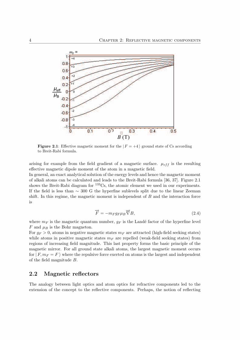
Figure 2.1: Effective magnetic moment for the |F = +4 〉 ground state of Cs accordingto Breit-Rabi formula.
arising for example from the field gradient of a magnetic surface. µeff is the resultingeffective magnetic dipole moment of the atom in a magnetic field.In general, an exact analytical solution of the energy levels and hence the magnetic momentof alkali atoms can be calculated and leads to the Breit-Rabi formula [36, 37]. Figure 2.1shows the Breit-Rabi diagram for 133Cs, the atomic element we used in our experiments.If the field is less than ∼ 300 G the hyperfine sublevels split due to the linear Zeemanshift. In this regime, the magnetic moment is independent of B and the interaction forceis
−→F = −mF gF µB
−→∇B, (2.4)
where mF is the magnetic quantum number, gF is the Lande factor of the hyperfine levelF and µB is the Bohr magneton.For gF > 0, atoms in negative magnetic states mF are attracted (high-field seeking states)while atoms in positive magnetic states mF are repelled (weak-field seeking states) fromregions of increasing field magnitude. This last property forms the basic principle of themagnetic mirror. For all ground state alkali atoms, the largest magnetic moment occursfor |F, mF = F 〉 where the repulsive force exerted on atoms is the largest and independentof the field magnitude B.
2.2 Magnetic reflectors
The analogy between light optics and atom optics for refractive components led to theextension of the concept to the reflective components. Perhaps, the notion of reflecting
2.2 Magnetic reflectors 5
Ideal mirror Typical mirror
b)a)
yy0
U
U0
y
B
B
B0
~ exp(-ky)
00
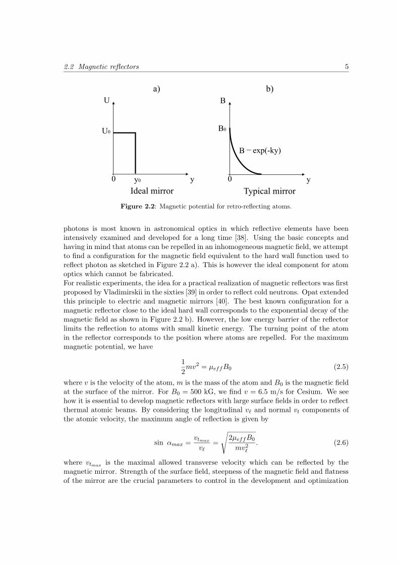
Figure 2.2: Magnetic potential for retro-reflecting atoms.
photons is most known in astronomical optics in which reflective elements have beenintensively examined and developed for a long time [38]. Using the basic concepts andhaving in mind that atoms can be repelled in an inhomogeneous magnetic field, we attemptto find a configuration for the magnetic field equivalent to the hard wall function used toreflect photon as sketched in Figure 2.2 a). This is however the ideal component for atomoptics which cannot be fabricated.For realistic experiments, the idea for a practical realization of magnetic reflectors was firstproposed by Vladimirskii in the sixties [39] in order to reflect cold neutrons. Opat extendedthis principle to electric and magnetic mirrors [40]. The best known configuration for amagnetic reflector close to the ideal hard wall corresponds to the exponential decay of themagnetic field as shown in Figure 2.2 b). However, the low energy barrier of the reflectorlimits the reflection to atoms with small kinetic energy. The turning point of the atomin the reflector corresponds to the position where atoms are repelled. For the maximummagnetic potential, we have
1
2mv2 = µeffB0 (2.5)
where v is the velocity of the atom, m is the mass of the atom and B0 is the magnetic fieldat the surface of the mirror. For B0 = 500 kG, we find v = 6.5 m/s for Cesium. We seehow it is essential to develop magnetic reflectors with large surface fields in order to reflectthermal atomic beams. By considering the longitudinal v` and normal vt components ofthe atomic velocity, the maximum angle of reflection is given by
sin αmax =vtmax
v`=
√
2µeffB0
mv2`
. (2.6)
where vtmaxis the maximal allowed transverse velocity which can be reflected by the
magnetic mirror. Strength of the surface field, steepness of the magnetic field and flatnessof the mirror are the crucial parameters to control in the development and optimization
6 Chapter 2: Reflective magnetic components
of magnetic reflectors. In the following, we present main the magnetic mirrors which havebeen realized in the laboratories.
2.2.1 Macroscopic permanent magnets
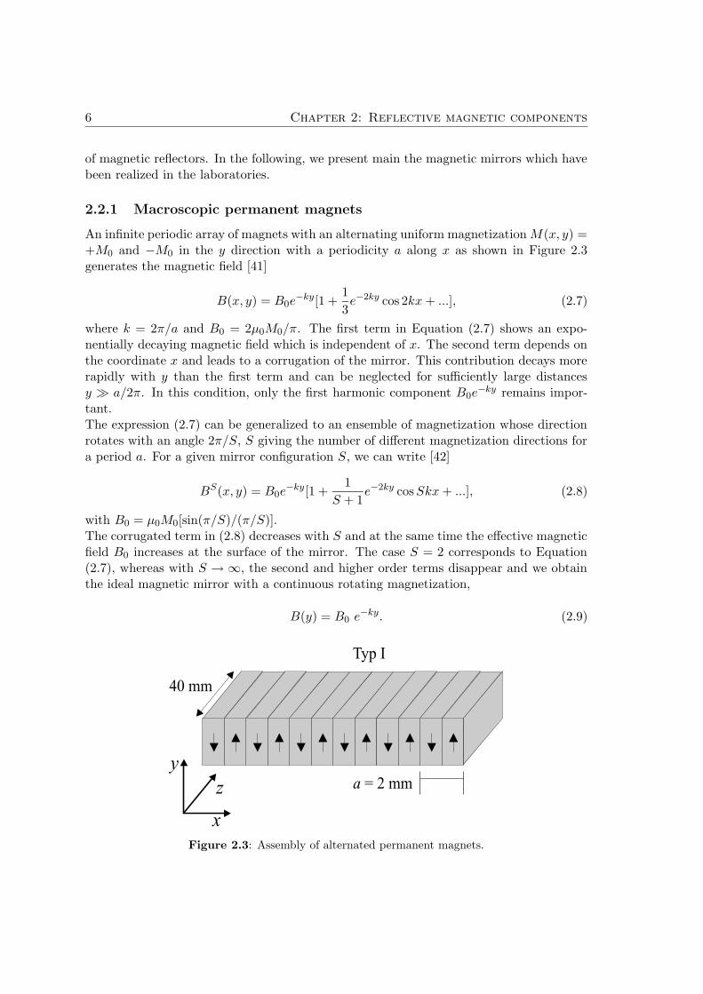
An infinite periodic array of magnets with an alternating uniform magnetization M(x, y) =+M0 and −M0 in the y direction with a periodicity a along x as shown in Figure 2.3generates the magnetic field [41]
B(x, y) = B0e−ky[1 +
1
3e−2ky cos 2kx + ...], (2.7)
where k = 2π/a and B0 = 2µ0M0/π. The first term in Equation (2.7) shows an expo-nentially decaying magnetic field which is independent of x. The second term depends onthe coordinate x and leads to a corrugation of the mirror. This contribution decays morerapidly with y than the first term and can be neglected for sufficiently large distancesy a/2π. In this condition, only the first harmonic component B0e
−ky remains impor-tant.The expression (2.7) can be generalized to an ensemble of magnetization whose directionrotates with an angle 2π/S, S giving the number of different magnetization directions fora period a. For a given mirror configuration S, we can write [42]
BS(x, y) = B0e−ky[1 +
1
S + 1e−2ky cos Skx + ...], (2.8)
with B0 = µ0M0[sin(π/S)/(π/S)].The corrugated term in (2.8) decreases with S and at the same time the effective magneticfield B0 increases at the surface of the mirror. The case S = 2 corresponds to Equation(2.7), whereas with S → ∞, the second and higher order terms disappear and we obtainthe ideal magnetic mirror with a continuous rotating magnetization,
B(y) = B0 e−ky. (2.9)
Figure 2.3: Assembly of alternated permanent magnets.
2.2 Magnetic reflectors 7
Two groups have constructed such mirrors configurations sketched in Figure 2.3 by as-sembling rare-earth permanent magnets. In Melbourne, researchers [41] realized a mirrorof alternated magnetization (S = 2) from neodymium-iron-boron (Nd-Fe-B) with 18 slabseach 1 mm wide, 20 mm long and 12 mm deep. The magnetic field B0 at the surface isabout 4.2 kG and the period a = 2 mm. To compensate for end effects at the center of themirror, two 0.5 mm-wide magnets with opposite magnetization where added at the endsof the array.In our group [42] a mirror of samarium-cobalt (Sm-Co) has been constructed in a S = 4configuration, i.e. with a rotating magnetization in 90 steps. The 90, 1 mm-wide, 90 mm-long and 5 mm-deep slabs generate a magnetic field of 1.1 T and the spatial period is 4 mm.By adding pieces of soft iron at each end sides, the influence of end effects on the wholemirror is compensated. With such a structure, the surface magnetic field has been in-creased to B0 = 1.18 T while the magnetic field roughness in Equation (2.8) decreased.In these macroscopic approaches, the magnitude of the surface field is large enough sothat atoms with large angle of incidence can be reflected. However the main disadvantagearises from the long period of the mirrors which inevitably destroys the imaging qualityof a reflected atomic beam.
2.2.2 Microscopic magnetic materials
The macroscopic approach shows that non-negligible contribution of fringe fields from theend sides arises at the center of the mirror. The difficulty to control roughness components,which scale over millimeter distances stimulated some groups to examine the benefits ofmicro-magnets mirrors.
Videotapes
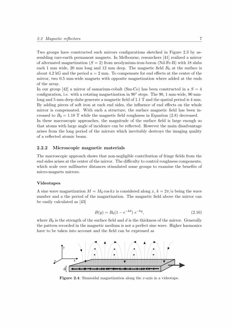
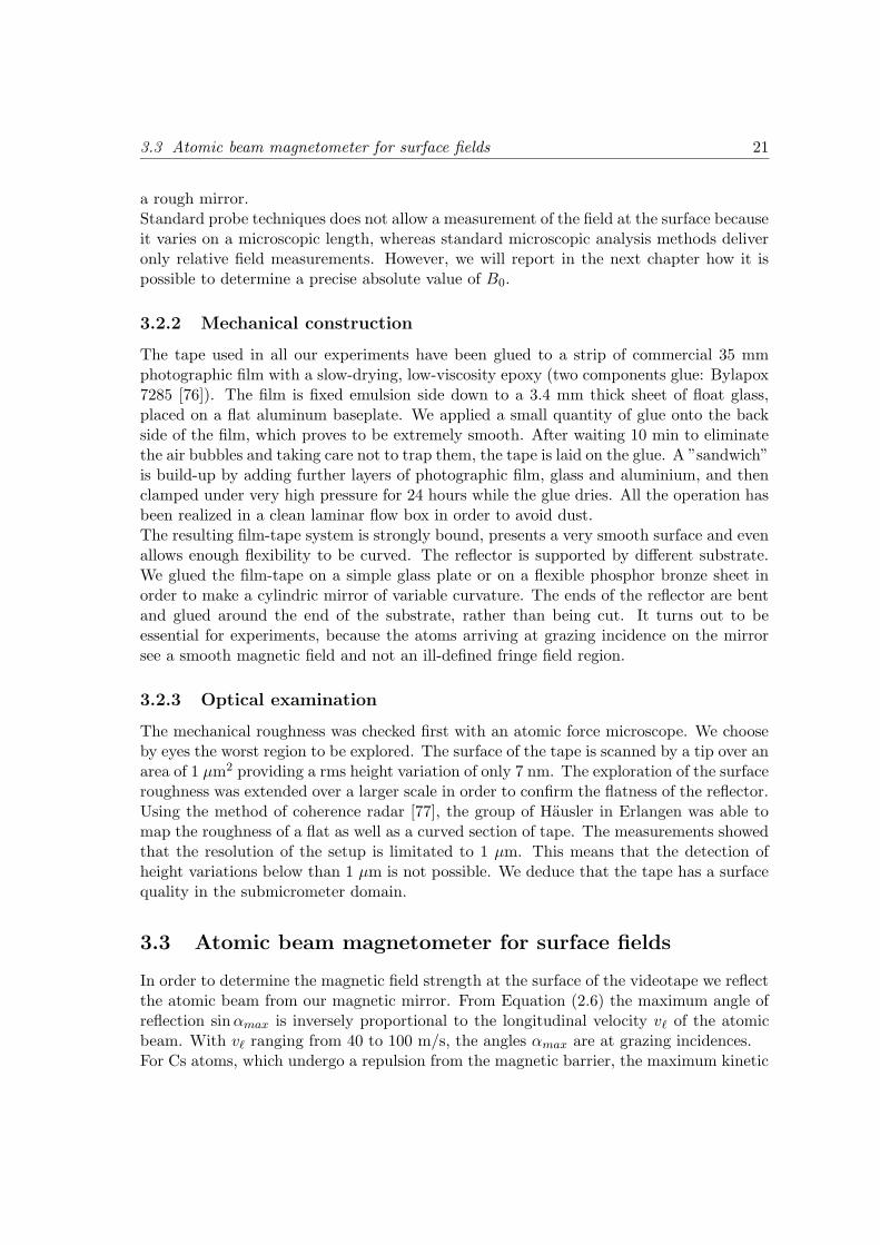
A sine wave magnetization M = M0 cos kx is considered along x, k = 2π/a being the wavenumber and a the period of the magnetization. The magnetic field above the mirror canbe easily calculated as [43]
B(y) = B0(1 − e−kd) e−ky, (2.10)
where B0 is the strength of the surface field and d is the thickness of the mirror. Generallythe pattern recorded in the magnetic medium is not a perfect sine wave. Higher harmonicshave to be taken into account and the field can be expressed as
x
y
z
d
Figure 2.4: Sinusoidal magnetization along the x-axis in a videotape.
8 Chapter 2: Reflective magnetic components
B(x, y) = B1e−ky1+1
2
∑
n>1
B2n
B21
e−2(n−1)ky+∑
n,m6=n
BnBm
B21
e−(n+m−2)ky cos((n−m)kx+δn−δm,
(2.11)
where Bn is the field amplitude of the nth harmonic at the surface of the mirror, δn is thephase of the magnetization. The first term in brackets is the fundamental correspondingto Equation (2.10). The second term is a slight correction to the exponential form of thefield. The last term contains all corrugations between different harmonics. We see thatthe corrugations of longest range decay as e−ky and corresponds to the beat between thefundamental and the second harmonic. All other terms decay faster and are less important
Recording a sinusoidal pattern in storing medium enables to use them as magnetic re-flectors. The direction of the magnetization lies in the plane of the mirror. It was firstdemonstrated with audio-tape [14], then extended to floppy disks [15, 16] and videotapes[17]. Recent experiments have been realized with a magnetic reflector fabricated fromcommercial half-inch videotape (Ampex 398 Betacam SP). The measured magnetic fieldat the surface is as high as 0.1 T with a spatial period of 13 µm. End effects are verysmall due to the centimeter-sized mirror and to the micrometer wavelength.Magnetic videotapes are prominent candidate in the family of potential reflectors becausethe roughness is very low. Dropping a cold cloud of atoms onto the surface turns out to bevery efficient for the number of reflected atoms, however the small surface field strengthturns out to be problematic for the reflection of an atomic beam limited often to grazingincidence. We will see in this work how we can overcome this difficulties.To improve the performances of magnetic tapes as mirror for atom optics, new challengescan be achieved with perpendicular magnetic recording as an alternative to the longitudi-nal magnetization [44, 45].
Magneto-optical materials
Another alternative to the videotape are magneto-optical ferrimagnetic films, which pos-sess a low Curie temperature. Magnetic structures can be written by focusing a laser beamin the presence of an external magnetic field. The large crystalline magnetic anisotropypresents an easy magnetization direction perpendicular to the plane of the film. TheEquation (2.7) is generalized to this case, in which the period has microscopic dimensions.Thus, all higher harmonic terms have small contributions.The group of Hannaford developed such mirrors with a film of TbFeCo [46]. The rema-nent magnetic field in the material reaches 0.24 T, but the film thickness produces only aneffective magnetic field of 0.08 T at the surface of the mirror. The period of the structureis 2.1 µm. The observation of reflection of cold atoms was reported to be up to about80 %.Magneto-optical materials are very promising as magnetic reflectors because of the flexi-bility to write complex magnetic patterns like cylindrical mirrors.
2.2 Magnetic reflectors 9
2.2.3 Current-carrying wires
For an infinite array of wires carrying alternated electric currents of equal magnitude Iin opposite directions, we obtain for the magnetic field an expression similar to Equation(2.7)
B(x, y) = B0e−ky(1 + e−2ky cos 2kx + ...), (2.12)
where k = 2π/a, a being twice the spacing between the wires, µ0 is the magnetic perme-ability in vacuum and B0 = 2µ0I/a.The corrugated term, which corresponds also to the second term in Equation (2.12), isthree times larger than the coefficient in Equation (2.7). But this device offers a lot ofpossibilities like variation, switching or modulation of the magnetic field by altering thecurrent flowing through the wires. Each element of the array carries exactly the samecurrent and produces the same magnetic flux.
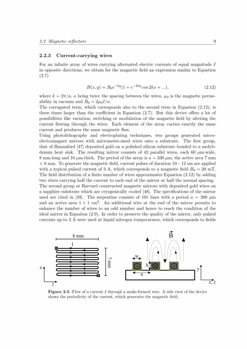
Using photolithography and electroplating techniques, two groups generated micro-electromagnet mirrors with micrometer-sized wires onto a substrate. The first group,that of Hannaford [47] deposited gold on a polished silicon substrate bonded to a molyb-denum heat sink. The resulting mirror consists of 42 parallel wires, each 60 µm-wide,8 mm-long and 10 µm-thick. The period of the array is a = 330 µm, the active area 7 mm× 8 mm. To generate the magnetic field, current pulses of duration 10−12 ms are appliedwith a typical pulsed current of 3 A, which corresponds to a magnetic field B0 = 20 mT.The field distribution of a finite number of wires approximates Equation (2.12) by addingtwo wires carrying half the current to each end of the mirror at half the normal spacing.The second group at Harvard constructed magnetic mirrors with deposited gold wires ona sapphire substrate which are cryogenically cooled [48]. The specifications of the mirrorused are cited in [49]. The serpentine consists of 101 lines with a period a = 200 µmand an active area 1 × 1 cm2. An additional wire at the end of the mirror permits toenhance the number of wires to an odd number and hence to reach the condition of theideal mirror in Equation (2.9). In order to preserve the quality of the mirror, only pulsedcurrents up to 3 A were used at liquid nitrogen temperatures, which corresponds to fields
y
x, z
x
z
w
a
h
I
8 mm
7 m
m
B
Figure 2.5: Flow of a current I through a snake-formed wire. A side view of the deviceshows the periodicity of the current, which generates the magnetic field.
10 Chapter 2: Reflective magnetic components
up to ∼ 0.3 T at the surface of the wires.In this scheme the surface field is mainly limited by the maximum current supported bythe wire. The small active area of the mirror enables to reflect samples of laser-cooledatoms and the reflection of an atomic beam at grazing incidence (1 mrad) has been alsoreported [50].
2.2.4 Natural crystals
Ferromagnetic materials present natural domain structures resulting from the minimiza-tion of the stray field to the free energy. This field is exploited in order to realize amagnetic mirror. Different techniques, like optical, magneto-optical as well as mechan-ical micro-scanning techniques, allow to observe the domains at the surface of samples.However, there is no way up to know to observe directly the interior domains [51].
Cobalt single crystal
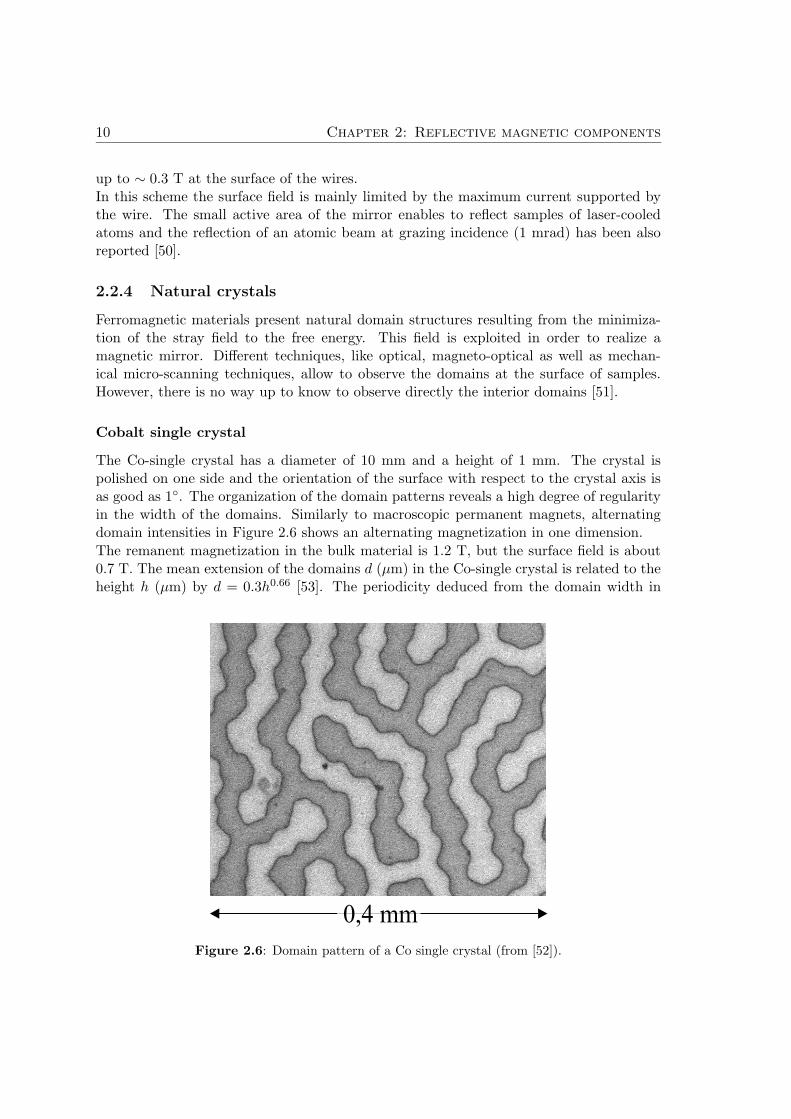
The Co-single crystal has a diameter of 10 mm and a height of 1 mm. The crystal ispolished on one side and the orientation of the surface with respect to the crystal axis isas good as 1. The organization of the domain patterns reveals a high degree of regularityin the width of the domains. Similarly to macroscopic permanent magnets, alternatingdomain intensities in Figure 2.6 shows an alternating magnetization in one dimension.
The remanent magnetization in the bulk material is 1.2 T, but the surface field is about0.7 T. The mean extension of the domains d (µm) in the Co-single crystal is related to theheight h (µm) by d = 0.3h0.66 [53]. The periodicity deduced from the domain width in
Figure 2.6: Domain pattern of a Co single crystal (from [52]).
2.2 Magnetic reflectors 11
Figure 2.6 is 31 µm. This value is in good agreement with that deduced from the previousformula.By dropping cold atoms of rubidium onto the surface of the crystal, it has been possibleto determine the surface roughness of the reflector corresponding to an angular variationof 3 mrad [52].
Sintered Nd-Fe-B
In the crystal the proportion of each element is Nd2Fe14B which is strongly magnetic.Due to the high magneto-crystalline anisotropy, the domain are largely oriented and inthis material they are magnetized by the processus of fabrication perpendicular to the sur-face. The spontaneous magnetization of a domain is 1.63 T [54]. The typical dimensionof the domains at the surface is 1 µm.A closer examination with a polarization microscope and a MFM (magnetic force micro-scope) shows that the domains are almost exclusively magnetized perpendicular to thesurface and they present a mean width of 1 µm [42]. For measurements with the MFM-tipat large distances from the surface, the spatial resolution decreases. This is an indicationthat the stray field decreases very fast and its strength depends however on the orientationof the crystallite axis and the normal of the surface.An atomic beam with a longitudinal velocity of 59 m/s has been reflected onto the surfaceof the crystal. The investigation showed that the measured magnetic field is 0.9 T whilethe given remanent magnetization is 1.2 T.
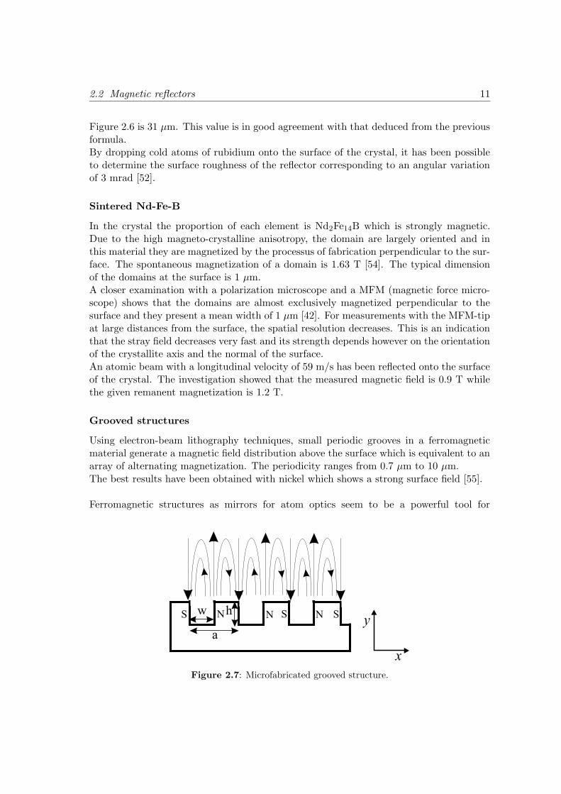
Grooved structures
Using electron-beam lithography techniques, small periodic grooves in a ferromagneticmaterial generate a magnetic field distribution above the surface which is equivalent to anarray of alternating magnetization. The periodicity ranges from 0.7 µm to 10 µm.
The best results have been obtained with nickel which shows a strong surface field [55].
Ferromagnetic structures as mirrors for atom optics seem to be a powerful tool for
Figure 2.7: Microfabricated grooved structure.
12 Chapter 2: Reflective magnetic components
the long term under the condition that it would be possible to have full control on thedynamics of the domain not only in thin films as it has still been shown [56] but also inbulk materials.
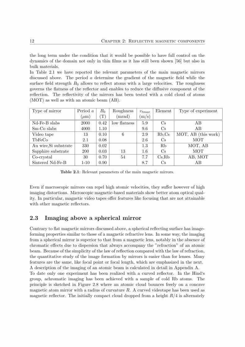
In Table 2.1 we have reported the relevant parameters of the main magnetic mirrorsdiscussed above. The period a determine the gradient of the magnetic field while thesurface field strength B0 allows to reflect atoms with a large velocities. The roughnessgoverns the flatness of the reflector and enables to reduce the diffusive component of thereflection. The reflectivity of the mirrors has been tested with a cold cloud of atoms(MOT) as well as with an atomic beam (AB).
Type of mirror Period a B0 Roughness vtmax Element Type of experiment(µm) (T) (mrad) (m/s)
Nd-Fe-B slabs 2000 0.42 low flatness 5.9 Cs ABSm-Co slabs 4000 1.10 9.6 Cs AB
Video tape 13 0.10 6 2.9 Rb,Cs MOT, AB (this work)TbFeCo 2.1 0.08 2.6 Cs MOT
Au wire,Si substrate 330 0.02 1.3 Rb MOT, ABSapphire substrate 200 0.03 13 1.6 Cs MOT
Co-crystal 30 0.70 54 7.7 Cs,Rb AB, MOTSintered Nd-Fe-B 1-10 0.90 8.7 Cs AB
Table 2.1: Relevant parameters of the main magnetic mirrors.
Even if macroscopic mirrors can repel high atomic velocities, they suffer however of highimaging distortions. Microscopic magnetic-based materials show better atom optical qual-ity. In particular, magnetic video tapes offer features like focusing that are not attainablewith other magnetic reflectors.
2.3 Imaging above a spherical mirror
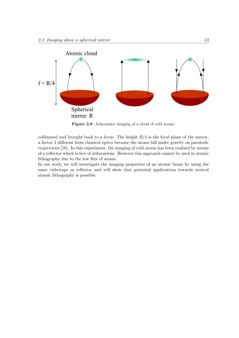
Contrary to flat magnetic mirrors discussed above, a spherical reflecting surface has image-forming properties similar to those of a magnetic refractive lens. In some way, the imagingfrom a spherical mirror is superior to that from a magnetic lens, notably in the absence ofchromatic effects due to dispersion that always accompany the ”refraction” of an atomicbeam. Because of the simplicity of the law of reflection compared with the law of refraction,the quantitative study of the image formation by mirrors is easier than for lenses. Manyfeatures are the same, like focal point or focal length, which are emphasized in the next.A description of the imaging of an atomic beam is calculated in detail in Appendix A.To date only one experiment has been realized with a curved reflector. In the Hind‘sgroup, achromatic imaging has been achieved with a sample of cold Rb atoms. Theprinciple is sketched in Figure 2.8 where an atomic cloud bounces freely on a concavemagnetic atom mirror with a radius of curvature R. A curved videotape has been used asmagnetic reflector. The initially compact cloud dropped from a height R/4 is alternately
2.3 Imaging above a spherical mirror 13
Figure 2.8: Achromatic imaging of a cloud of cold atoms.
collimated and brought back to a focus. The height R/4 is the focal plane of the mirror,a factor 2 different from classical optics because the atoms fall under gravity on parabolictrajectories [16]. In this experiment, the imaging of cold atoms has been realized by meansof a reflector which is free of abberations. However this approach cannot be used in atomiclithography due to the low flux of atoms.In our work, we will investigate the imaging properties of an atomic beam by using thesame videotape as reflector and will show that potential applications towards neutralatomic lithography is possible.

Chapter 3
Whispering gallery mirror for
atom beams
Among the reflectors presented in Chapter 2, we have chosen the magnetic videotapebecause of its simplicity. Also its flexibility enables to find easily any geometrical shapefor applications in magnetic reflective atom optics.In this Chapter, we study the reflection properties of a Zeeman slowed atomic beam andshow that videotapes are potential candidates for imaging with atomic beams [57].
3.1 Zeeman-slowed atomic beam
Laser cooling methods provide the possibility to obtain very well collimated and slowatomic beams. Different approaches can be implemented for decelerating a thermal atomicbeam largely described in [58]. With these intense sources, we investigated the deflectionof a polarized Cesium atomic beam by a magnetic mirror.
3.1.1 Principle of operation
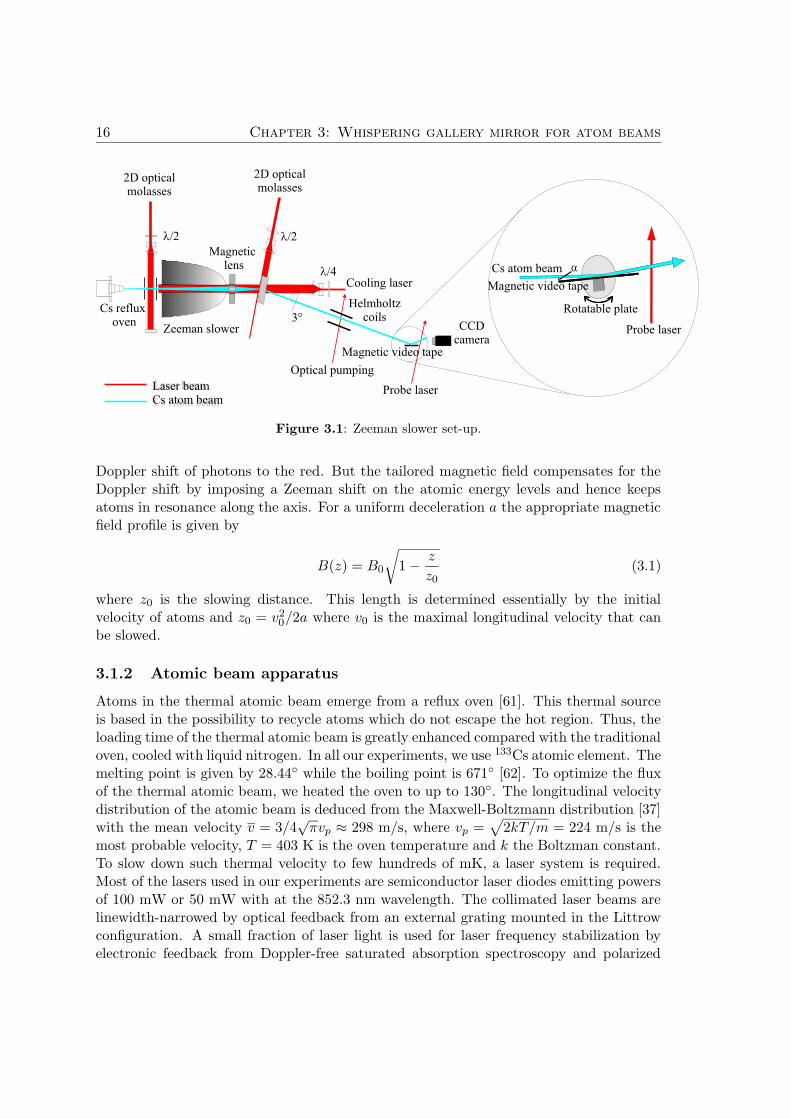
It is well known that a laser beam exerts a radiation force on free atoms and can be usedfor radiative deceleration of an atomic beam. One way is to direct a laser opposite to themotion of an atomic beam. However as the atoms in the beam slow down, their chang-ing Doppler shift take them out of resonance. To overcome this problem, two differentmethods can be used. The first, by sweeping the laser beam frequency to keep it in res-onance with the atomic-resonance [59]. The second, the method we have chosen consistsin varying the atomic resonance frequency with an inhomogeneous magnetic field to keepthe slowed atoms in resonance with the fixed frequency of the laser [60].The Zeeman-slowed atomic beam shown in Figure 3.1 has been fully described and charac-terized in [42, 22]. A thermal atomic beam enters the region of strong magnetic field, whereatoms are cooled along the beam axis. A σ+-polarized laser beam counter-propagates theatomic beam and slows atoms by momentum transfer. During the decelerating process,the absorption probability in the moving coordinate frame of atoms decreases due to the
15
16 Chapter 3: Whispering gallery mirror for atom beams
Laser beam
Cs Atom beam
l/2 l/2
l/4 a
2D opticalmolasses
Zeeman slower
Optical pumping
Cooling laser
Cs atom beam
Rotatable plate
CCDcamera
Probe laser
Probe laser
Magnetic video tape
Magnetic video tape
Helmholtzcoils
Cs refluxoven
2D opticalmolasses
Magneticlens
Laser beamCs atom beam
3°
Figure 3.1: Zeeman slower set-up.
Doppler shift of photons to the red. But the tailored magnetic field compensates for theDoppler shift by imposing a Zeeman shift on the atomic energy levels and hence keepsatoms in resonance along the axis. For a uniform deceleration a the appropriate magneticfield profile is given by
B(z) = B0
√
1 − z
z0(3.1)
where z0 is the slowing distance. This length is determined essentially by the initialvelocity of atoms and z0 = v2
0/2a where v0 is the maximal longitudinal velocity that canbe slowed.
3.1.2 Atomic beam apparatus
Atoms in the thermal atomic beam emerge from a reflux oven [61]. This thermal sourceis based in the possibility to recycle atoms which do not escape the hot region. Thus, theloading time of the thermal atomic beam is greatly enhanced compared with the traditionaloven, cooled with liquid nitrogen. In all our experiments, we use 133Cs atomic element. Themelting point is given by 28.44 while the boiling point is 671 [62]. To optimize the fluxof the thermal atomic beam, we heated the oven to up to 130. The longitudinal velocitydistribution of the atomic beam is deduced from the Maxwell-Boltzmann distribution [37]with the mean velocity v = 3/4
√πvp ≈ 298 m/s, where vp =
√
2kT/m = 224 m/s is themost probable velocity, T = 403 K is the oven temperature and k the Boltzman constant.To slow down such thermal velocity to few hundreds of mK, a laser system is required.Most of the lasers used in our experiments are semiconductor laser diodes emitting powersof 100 mW or 50 mW with at the 852.3 nm wavelength. The collimated laser beams arelinewidth-narrowed by optical feedback from an external grating mounted in the Littrowconfiguration. A small fraction of laser light is used for laser frequency stabilization byelectronic feedback from Doppler-free saturated absorption spectroscopy and polarized
3.1 Zeeman-slowed atomic beam 17
absorption spectroscopy in Cs cells [63, 64, 65].Our reference laser provides a narrow linewidth (∼ 10 kHz) by resonant feedback froman external confocal cavity. A thin glass in front of the laser chip enables to select agiven longitudinal laser mode and hence to lock it at the given optical transition with astandard polarization spectroscopy [66]. The decelerating laser is stabilized to the referencelaser through an heterodyne phase-locked loop [67], owing a blue detuning frequencyup to 250 MHz. This allows us to choose the end velocity of the slowed atomic beamby tuning the frequency of the laser beam. Beside a small longitudinal velocity of theatomic beam, a small atomic angular spread is desired for experiments in reflective atomoptics. The preparation of the slow atomic beam with small transverse velocity requiresthe implementation of transverse cooling processes at different stage of the experimentalsetup.
3.1.3 Preparation of the atomic beam
Before the atomic beam arrives in the experimental stage, different transverse manipula-tions have been realized. These have been reported in [42, 68], we will outline here themain results.
Transverse optical collimation
The transverse expansion of the thermal atomic beam leaving the oven proved to beunsuitable for a good longitudinal slowing process in the inhomogeneous magnetic field.To solve this problem, a molasses with elliptically shaped light fields (5× 45) mm in a lin
⊥ lin configuration ensures a sub-Doppler transverse cooling along the atomic beam axis[69, 70, 71]. Two apertures (∅ = 3 mm) are inserted between the oven and the slowingzone to reduce the divergence of the atomic beam as well as to stop the uncollimated fastatoms. The velocity capture range of the laser beam is larger than the maximal transversevelocity of the atomic beam so that all atoms are transversally cooled below the Dopplerlimit i.e down to 5 cm/s. This has also the advantage of increasing the atomic beam fluxbefore the longitudinal deceleration.
Deflection and transverse collimation
At the end of the decelerating stage strong permanent magnets decouple atoms from theslowing process so that atoms leaving the slowing stage in the
∣
∣ 62S1/2
⟩
scatter very fewphotons ground state which do not contribute to a longitudinal spread of the atomicbeam. Additional heating from the randomly scattered photons results in the transversespread of the atomic beam. In order to compensate this effect, a magnetic hexapol lensfrom permanent magnets [13] focus the atomic beam in the magnetic hyperfine sub-level|F = +4, mF = +4 〉 inside a 2D optical molasses module formed by four mirrors onto analuminum frame, which retro-reflects a single laser beam allowing a lin ⊥ lin configurationfor sub-Doppler cooling. The compression set-up is tilted by 3 with respect to the slowingaxis in such a way to separate the slow atomic beam from the on-axis cooling laser beamand to eliminate the unslowed atoms from the atomic beam.
18 Chapter 3: Whispering gallery mirror for atom beams
Optical pumping
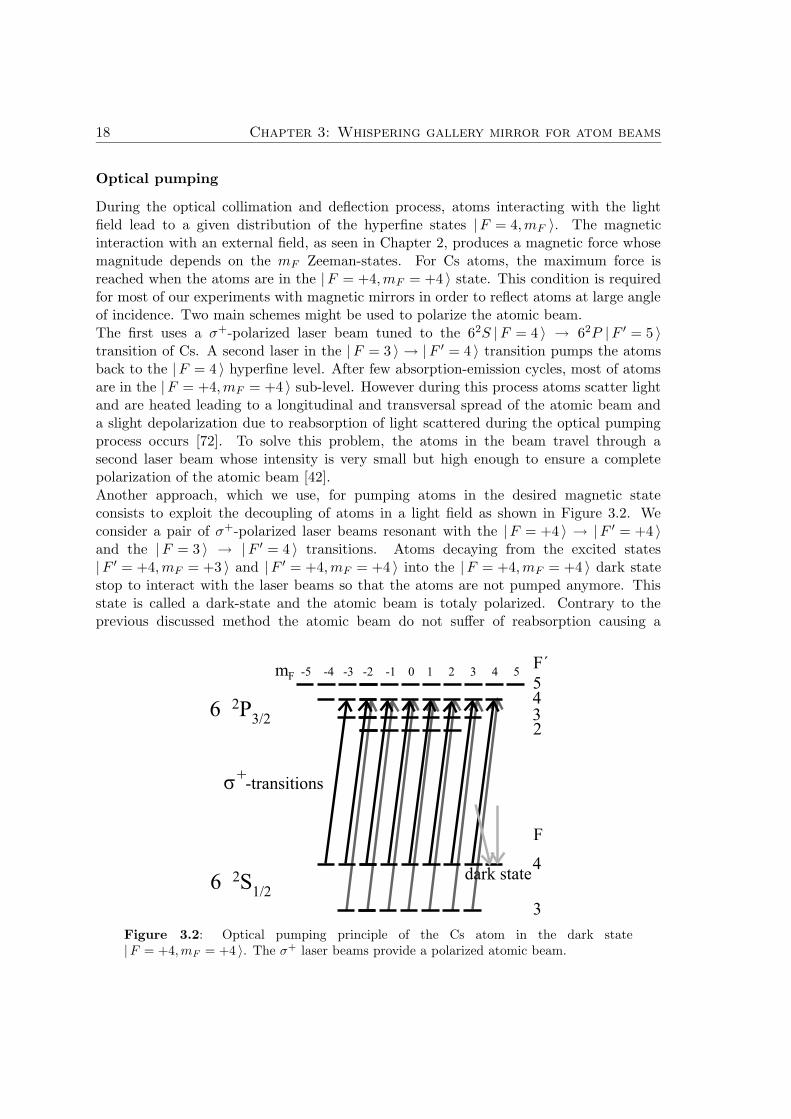
During the optical collimation and deflection process, atoms interacting with the lightfield lead to a given distribution of the hyperfine states |F = 4, mF 〉. The magneticinteraction with an external field, as seen in Chapter 2, produces a magnetic force whosemagnitude depends on the mF Zeeman-states. For Cs atoms, the maximum force isreached when the atoms are in the |F = +4, mF = +4 〉 state. This condition is requiredfor most of our experiments with magnetic mirrors in order to reflect atoms at large angleof incidence. Two main schemes might be used to polarize the atomic beam.The first uses a σ+-polarized laser beam tuned to the 62S |F = 4 〉 → 62P |F ′ = 5 〉transition of Cs. A second laser in the |F = 3 〉 → |F ′ = 4 〉 transition pumps the atomsback to the |F = 4 〉 hyperfine level. After few absorption-emission cycles, most of atomsare in the |F = +4, mF = +4 〉 sub-level. However during this process atoms scatter lightand are heated leading to a longitudinal and transversal spread of the atomic beam anda slight depolarization due to reabsorption of light scattered during the optical pumpingprocess occurs [72]. To solve this problem, the atoms in the beam travel through asecond laser beam whose intensity is very small but high enough to ensure a completepolarization of the atomic beam [42].Another approach, which we use, for pumping atoms in the desired magnetic stateconsists to exploit the decoupling of atoms in a light field as shown in Figure 3.2. Weconsider a pair of σ+-polarized laser beams resonant with the |F = +4 〉 → |F ′ = +4 〉and the |F = 3 〉 → |F ′ = 4 〉 transitions. Atoms decaying from the excited states|F ′ = +4, mF = +3 〉 and |F ′ = +4, mF = +4 〉 into the |F = +4, mF = +4 〉 dark statestop to interact with the laser beams so that the atoms are not pumped anymore. Thisstate is called a dark-state and the atomic beam is totaly polarized. Contrary to theprevious discussed method the atomic beam do not suffer of reabsorption causing a
Figure 3.2: Optical pumping principle of the Cs atom in the dark state|F = +4,mF = +4 〉. The σ+ laser beams provide a polarized atomic beam.
3.2 Preparation of the reflector 19
depolarization of the atomic beam. Once atoms are in the dark state, they stay there andleave the interaction region undisturbed.To probe the efficiency of the atomic beam polarization, a small magnet of NdFeB ismounted on a translation stage perpendicular to the atomic beam. Without opticalpumping the unpolarized atomic beam is divided into nine different atomic beamscorresponding to the different mF magnetic states. Turning on the polarizing beam morethan 90 % of atoms are pumped in the mF = +4 state.
The collimated and polarized atomic beam arrives in the experimental zone withtypical tunable velocities ranging in the domain 40-100 m/s. However, the atomic beamflux decreases for slow velocities. The atomic beam cross-section is ∅ = 4 mm forvelocities ranging from 70 m/s to 85 m/s while the transverse velocity is vt = 0.05 m/s.
3.2 Preparation of the reflector
Magnetic materials with large active area have the advantage to minimize boundary fieldeffects at the center of the mirror. Commercially available videotape type AMPEX 398Betacam SP offers this possibility. Beside a remanent field of 2.3 kG, the 12 mm-widetape consists of a superposition of three layers: a Polyethylene foil, a 3.5 µm magneticfilm containing small particles (∼ 100 nm long, ∼ 10 nm diameter) and a graphite backcoating [73].
3.2.1 Magnetic recording
Using a standard data storage tape drive, a custom-made recording head enables to writethe a sine wave pattern in the videotape. The head has a gap of 12 µm and is 12.7 mmlong, so that the entire width of the tape can be recorded. With a 2 kHz signal and a tapespeed of 6 cm/s, a magnetization M
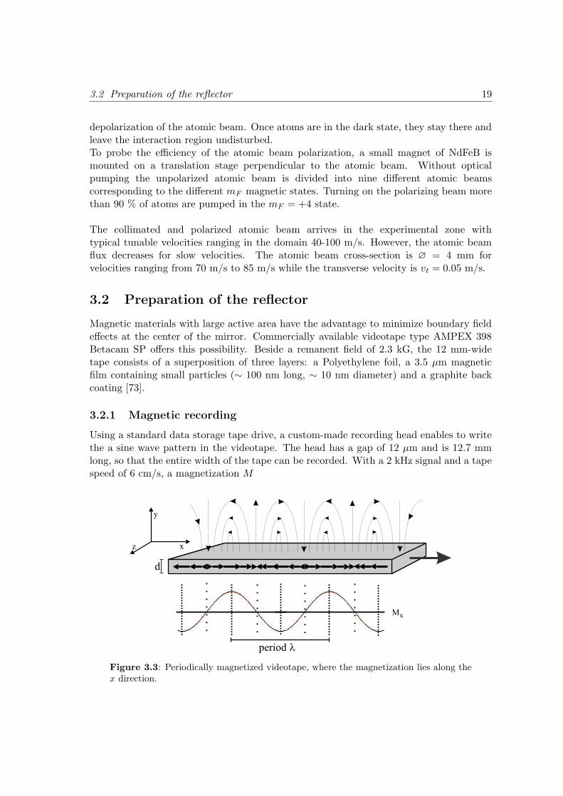
Figure 3.3: Periodically magnetized videotape, where the magnetization lies along thex direction.
20 Chapter 3: Whispering gallery mirror for atom beams
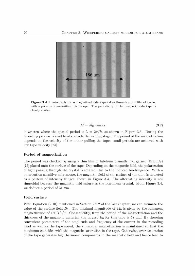
Figure 3.4: Photograph of the magnetized videotape taken through a thin film of garnetwith a polarization-sensitive microscope. The periodicity of the magnetic videotape isclearly visible.
M = M0 · sin kx, (3.2)
is written where the spatial period is λ = 2π/k, as shown in Figure 3.3. During therecording process, a read head controls the writing stage. The period of the magnetizationdepends on the velocity of the motor pulling the tape: small periods are achieved withlow tape velocity [74].
Period of magnetization
The period was checked by using a thin film of lutetium bismuth iron garnet (Bi:LuIG)[75] placed onto the surface of the tape. Depending on the magnetic field, the polarizationof light passing through the crystal is rotated, due to the induced birefringence. With apolarization-sensitive microscope, the magnetic field at the surface of the tape is detectedas a pattern of intensity fringes, shown in Figure 3.4. The alternating intensity is notsinusoidal because the magnetic field saturates the non-linear crystal. From Figure 3.4,we deduce a period of 31 µm.
Field surface
With Equation (2.10) mentioned in Section 2.2.2 of the last chapter, we can estimate thevalue of the surface field B0. The maximal magnitude of M0 is given by the remanentmagnetization of 180 kA/m. Consequently, from the period of the magnetization and thethickness of the magnetic material, the largest B0 for this tape is 58 mT. By choosingconvenient parameters of the amplitude and frequency of the current in the recordinghead as well as the tape speed, the sinusoidal magnetization is maintained so that themaximum coincides with the magnetic saturation in the tape. Otherwise, over-saturationof the tape generates high harmonic components in the magnetic field and hence lead to
3.3 Atomic beam magnetometer for surface fields 21
a rough mirror.Standard probe techniques does not allow a measurement of the field at the surface becauseit varies on a microscopic length, whereas standard microscopic analysis methods deliveronly relative field measurements. However, we will report in the next chapter how it ispossible to determine a precise absolute value of B0.
3.2.2 Mechanical construction
The tape used in all our experiments have been glued to a strip of commercial 35 mmphotographic film with a slow-drying, low-viscosity epoxy (two components glue: Bylapox7285 [76]). The film is fixed emulsion side down to a 3.4 mm thick sheet of float glass,placed on a flat aluminum baseplate. We applied a small quantity of glue onto the backside of the film, which proves to be extremely smooth. After waiting 10 min to eliminatethe air bubbles and taking care not to trap them, the tape is laid on the glue. A ”sandwich”is build-up by adding further layers of photographic film, glass and aluminium, and thenclamped under very high pressure for 24 hours while the glue dries. All the operation hasbeen realized in a clean laminar flow box in order to avoid dust.The resulting film-tape system is strongly bound, presents a very smooth surface and evenallows enough flexibility to be curved. The reflector is supported by different substrate.We glued the film-tape on a simple glass plate or on a flexible phosphor bronze sheet inorder to make a cylindric mirror of variable curvature. The ends of the reflector are bentand glued around the end of the substrate, rather than being cut. It turns out to beessential for experiments, because the atoms arriving at grazing incidence on the mirrorsee a smooth magnetic field and not an ill-defined fringe field region.
3.2.3 Optical examination
The mechanical roughness was checked first with an atomic force microscope. We chooseby eyes the worst region to be explored. The surface of the tape is scanned by a tip over anarea of 1 µm2 providing a rms height variation of only 7 nm. The exploration of the surfaceroughness was extended over a larger scale in order to confirm the flatness of the reflector.Using the method of coherence radar [77], the group of Hausler in Erlangen was able tomap the roughness of a flat as well as a curved section of tape. The measurements showedthat the resolution of the setup is limitated to 1 µm. This means that the detection ofheight variations below than 1 µm is not possible. We deduce that the tape has a surfacequality in the submicrometer domain.
3.3 Atomic beam magnetometer for surface fields
In order to determine the magnetic field strength at the surface of the videotape we reflectthe atomic beam from our magnetic mirror. From Equation (2.6) the maximum angle ofreflection sin αmax is inversely proportional to the longitudinal velocity v` of the atomicbeam. With v` ranging from 40 to 100 m/s, the angles αmax are at grazing incidences.For Cs atoms, which undergo a repulsion from the magnetic barrier, the maximum kinetic
22 Chapter 3: Whispering gallery mirror for atom beams
energy is compensated by the maximum potential energy at the turning point which isvery close to the surface and hence we can deduce the surface field B0 from
B0 =1
2
m
µBv2t . (3.3)
We see that the determination of the atomic beam velocity will allow us to find the effectivemagnetic field B0 at the surface of the mirror.
3.3.1 Experimental realization
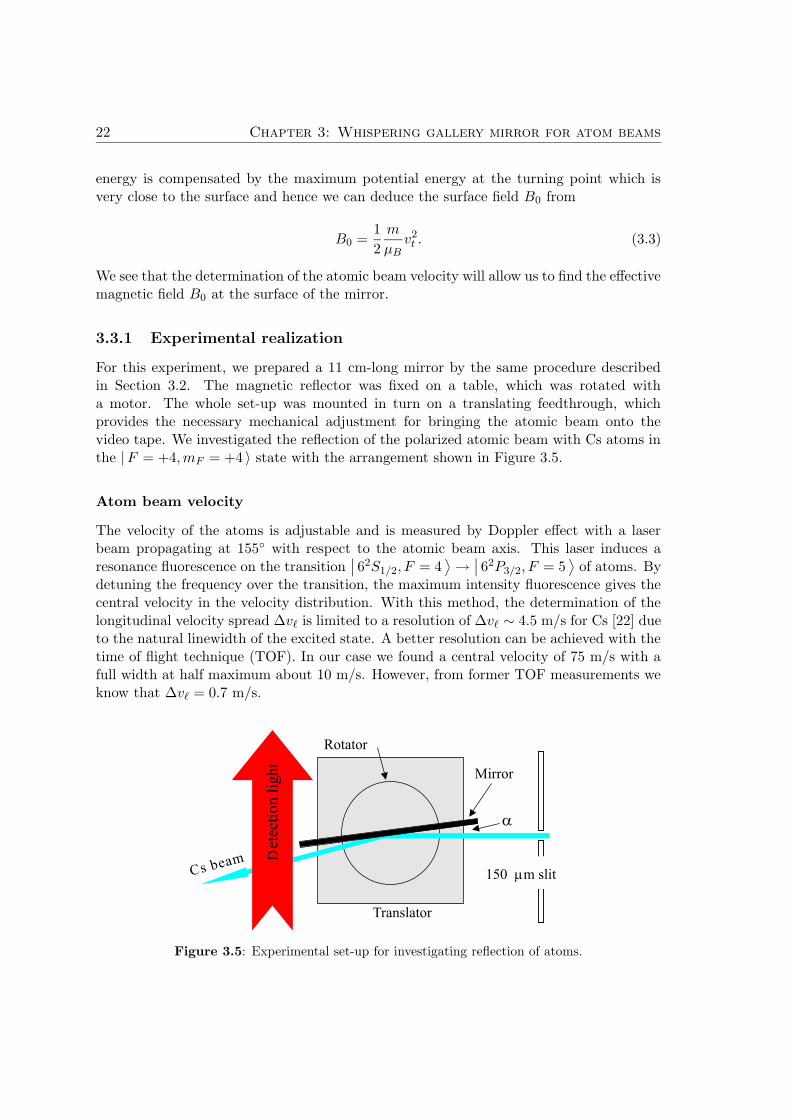
For this experiment, we prepared a 11 cm-long mirror by the same procedure describedin Section 3.2. The magnetic reflector was fixed on a table, which was rotated witha motor. The whole set-up was mounted in turn on a translating feedthrough, whichprovides the necessary mechanical adjustment for bringing the atomic beam onto thevideo tape. We investigated the reflection of the polarized atomic beam with Cs atoms inthe |F = +4, mF = +4 〉 state with the arrangement shown in Figure 3.5.
Atom beam velocity
The velocity of the atoms is adjustable and is measured by Doppler effect with a laserbeam propagating at 155 with respect to the atomic beam axis. This laser induces aresonance fluorescence on the transition
∣
∣ 62S1/2, F = 4⟩
→∣
∣ 62P3/2, F = 5⟩
of atoms. Bydetuning the frequency over the transition, the maximum intensity fluorescence gives thecentral velocity in the velocity distribution. With this method, the determination of thelongitudinal velocity spread ∆v` is limited to a resolution of ∆v` ∼ 4.5 m/s for Cs [22] dueto the natural linewidth of the excited state. A better resolution can be achieved with thetime of flight technique (TOF). In our case we found a central velocity of 75 m/s with afull width at half maximum about 10 m/s. However, from former TOF measurements weknow that ∆v` = 0.7 m/s.
Translator
Rotator
Mirror
150 mm slitCs beam
a
etec
tion
lih
tD
g
Figure 3.5: Experimental set-up for investigating reflection of atoms.
3.3 Atomic beam magnetometer for surface fields 23
Effective surface of the mirror
The physical width of the atomic beam is limited by a first slit S1 150 µm wide situated20 cm upstream from the center of the mirror, and with a second slit S2 of 700 µm located95 cm away from the mirror, the geometrical angular spread is constrained to 0.6 mrad.The maximum transverse velocity allowed in the atomic beam after S1 is a sub-Dopplervelocity of 4.5 cm/s. The minimum mirror angle α required to reflect the whole atomicbeam is α = 3 mrad.
Reflection angle calibration
A helium-neon (He-Ne) laser adjusted to the both slits defines the incident atomic beamaxis. The atom reflector mounted on a motor-controlled stage described in the previouschapter, is translated laterally towards the parallel red laser light and crosses it. Themirror angle α is changed until the He-Ne laser beam extends over the mirror surface anda fraction of light is still observable through the slit S2. Therefore a red line on the darkmirror surface can be distinguished. There, the orientation of the mirror corresponds toour reference angle α0 = 0 where no reflections of atoms occur.The quality of this adjustment can be controlled by cutting laterally the atomic beamwith the mirror, which lower the beam fluorescence intensity up to half its maximal value.Moving the rotator to few degrees in the opposite direction symmetrically to α0 decreasesthe fluorescence intensity to a same level.
The reflected atoms are detected by passing through a resonant vertical light sheetwith a power of 2 mW, where they fluoresce. By mean of a cylinder lens, the laser beamis focused in the vertical plane to few millimeter in the vertical plane. A charge-coupleddevice CCD camera collects the scattered light from the atomic beam. The intensity ofthe fluorescence gives the relative intensity of the reflected atoms.
3.3.2 Results
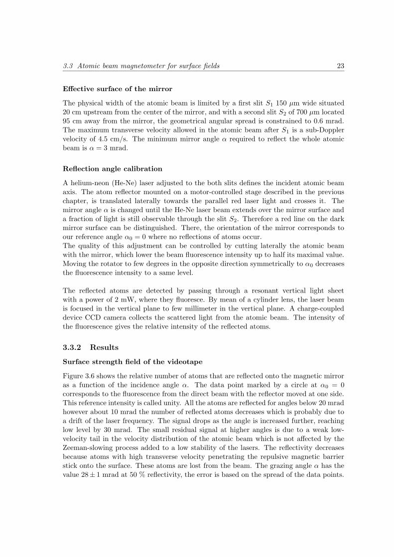
Surface strength field of the videotape
Figure 3.6 shows the relative number of atoms that are reflected onto the magnetic mirroras a function of the incidence angle α. The data point marked by a circle at α0 = 0corresponds to the fluorescence from the direct beam with the reflector moved at one side.This reference intensity is called unity. All the atoms are reflected for angles below 20 mradhowever about 10 mrad the number of reflected atoms decreases which is probably due toa drift of the laser frequency. The signal drops as the angle is increased further, reachinglow level by 30 mrad. The small residual signal at higher angles is due to a weak low-velocity tail in the velocity distribution of the atomic beam which is not affected by theZeeman-slowing process added to a low stability of the lasers. The reflectivity decreasesbecause atoms with high transverse velocity penetrating the repulsive magnetic barrierstick onto the surface. These atoms are lost from the beam. The grazing angle α has thevalue 28± 1 mrad at 50 % reflectivity, the error is based on the spread of the data points.
24 Chapter 3: Whispering gallery mirror for atom beams
0 10 20 30 40
0.0
0.2
0.4
0.6
0.8
1.0
1.2re
lati
ve
ato
mn
um
be
r
Incidence angle (mrad)
Figure 3.6: Relative flux of atoms that have been reflected from the tape as functionof the angle of incidence at longitudinal velocity of 75 m/s. The reflectivity starts todecrease for angles larger than ∼ 20. This provides information on the magnetic fieldat the surface.
Thus, the normal velocity is vt = v` sin α = 2.1±0.1 m/s. From Equation (3.3) we deducethe surface field of our reflector being B0 = 53± 5 mT. The value is slightly less than theexpected value 58 mT of the saturated magnetization.The major contribution to the width of the step originates from the velocity distributionof atoms in the beam. The effect of the angular spread is negligible and no evidence ofexcess width have been observed due to the roughness of the mirror.The flat grazing incidence mirror works as expected: all atoms are reflected and themeasured surface field B0 is in good agreement with the calculated value.
3.4 Whispering gallery
The previous experiment shows that we are faced with a typical problem known in x-ray optics, where reflections occur at grazing incidence. Multiple grazing incidences in awhispering-gallery geometry enable to deviate the atomic beam at large angles.
3.4.1 Multiple bounces
Resulting potential
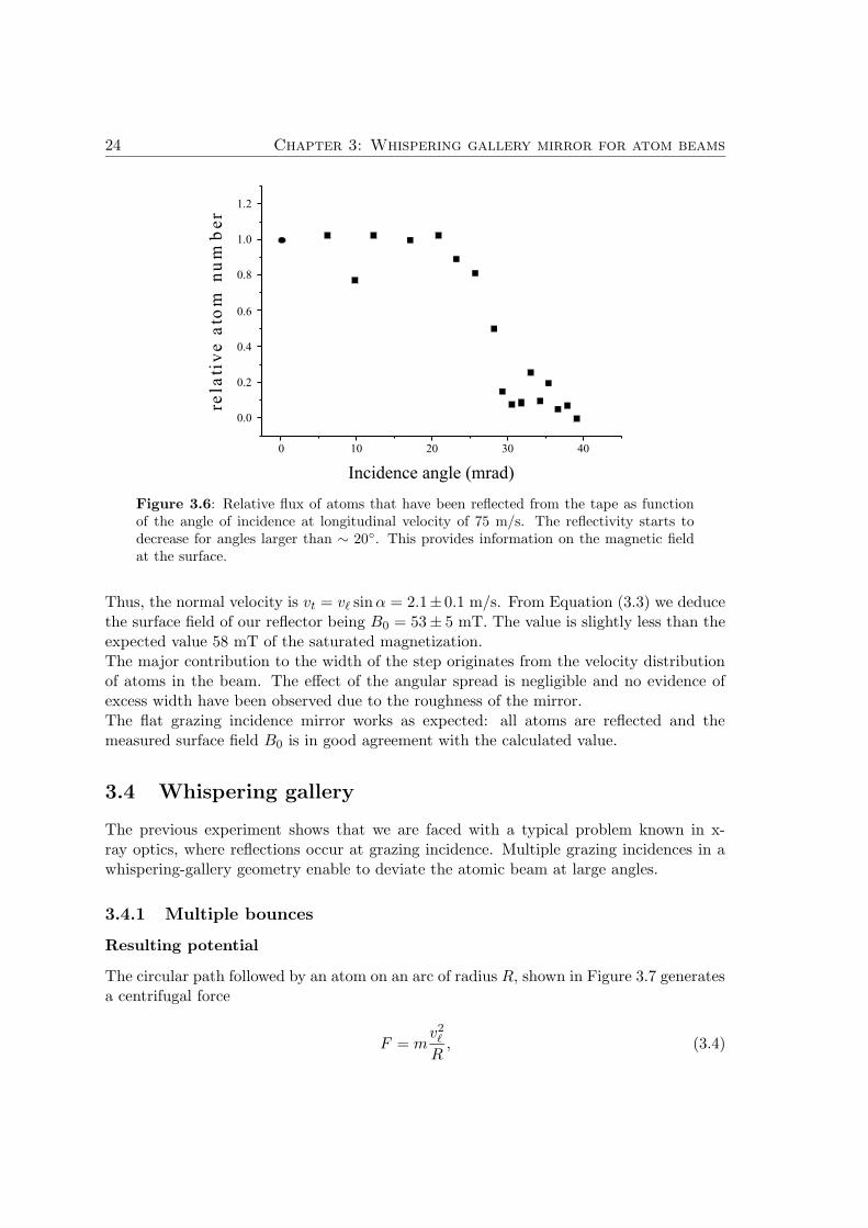
The circular path followed by an atom on an arc of radius R, shown in Figure 3.7 generatesa centrifugal force
F = mv2`
R, (3.4)
3.4 Whispering gallery 25
Figure 3.7: The whispering-gallery geometry.
which give rise to a pseudopotential at a small distance y from the surface of the mirror.Together with the magnetic potential from the tape, the total potential U(r) is
U(r) = µBB0e−kr + m
v2`
Rr. (3.5)
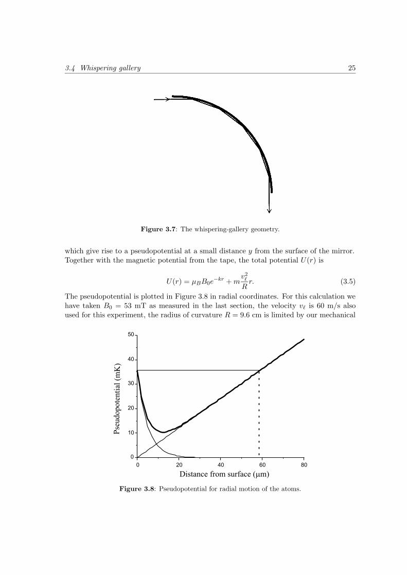
The pseudopotential is plotted in Figure 3.8 in radial coordinates. For this calculation wehave taken B0 = 53 mT as measured in the last section, the velocity v` is 60 m/s alsoused for this experiment, the radius of curvature R = 9.6 cm is limited by our mechanical
Figure 3.8: Pseudopotential for radial motion of the atoms.
26 Chapter 3: Whispering gallery mirror for atom beams
construction.In principle, the minimum radius of curvature Rmin still allowing a transmission of atomsin the whispering-gallery is given, when the centrifugal force mv2/Rmin is equal to themaximum magnetic force kµB,
Rmin =mv2
kµB. (3.6)
We find Rmin = 8.2 mm with v = 60 m/s, B = 0.05 T, k = 2π/a, a = 31 µm andµB/m = 42.Atoms with velocity vt = 0 experience radial oscillations in the potential shown in Figure3.8. Atoms incident with impact parameters higher than 59 µm collide onto the surfaceand are lost from the atomic beam, due to their relative higher centrifugal energy than themagnetic energy at the surface (36 mK) needed to reflect them. Thus the channel-widthof the whispering gallery is narrower than the 330 µm width of the atomic beam. Howeverthe angular acceptance of ±35 mrad (at the center of the channel) allows radial velocityof 2.1 m/s, which is much larger than the angular spread 0.6 mrad of the atomic beam.
Counting reflections
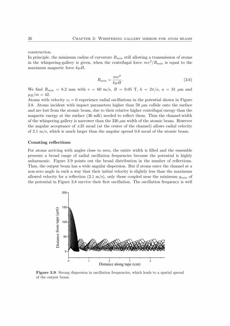
For atoms arriving with angles close to zero, the entire width is filled and the ensemblepresents a broad range of radial oscillation frequencies because the potential is highlyanharmonic. Figure 3.9 points out the broad distribution in the number of reflections.Thus, the output beam has a wide angular dispersion. But if atoms enter the channel at anon-zero angle in such a way that their initial velocity is slightly less than the maximumallowed velocity for a reflection (2.1 m/s), only those coupled near the minimum ymin ofthe potential in Figure 3.8 survive their first oscillation. The oscillation frequency is well
Figure 3.9: Strong dispersion in oscillation frequencies, which leads to a spatial spreadof the output beam.
3.4 Whispering gallery 27
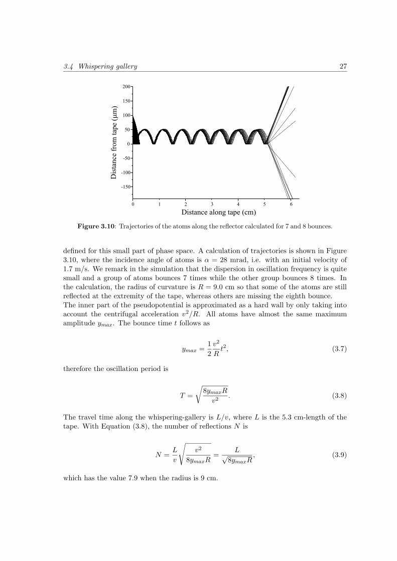
Figure 3.10: Trajectories of the atoms along the reflector calculated for 7 and 8 bounces.
defined for this small part of phase space. A calculation of trajectories is shown in Figure3.10, where the incidence angle of atoms is α = 28 mrad, i.e. with an initial velocity of1.7 m/s. We remark in the simulation that the dispersion in oscillation frequency is quitesmall and a group of atoms bounces 7 times while the other group bounces 8 times. Inthe calculation, the radius of curvature is R = 9.0 cm so that some of the atoms are stillreflected at the extremity of the tape, whereas others are missing the eighth bounce.The inner part of the pseudopotential is approximated as a hard wall by only taking intoaccount the centrifugal acceleration v2/R. All atoms have almost the same maximumamplitude ymax. The bounce time t follows as
ymax =1
2
v2
Rt2, (3.7)
therefore the oscillation period is
T =
√
8ymaxR
v2. (3.8)
The travel time along the whispering-gallery is L/v, where L is the 5.3 cm-length of thetape. With Equation (3.8), the number of reflections N is
N =L
v
√
v2
8ymaxR=
L√8ymaxR
, (3.9)
which has the value 7.9 when the radius is 9 cm.

28 Chapter 3: Whispering gallery mirror for atom beams
Figure 3.11: The sinusoidally recorded tape is glued to a metal strip that can be bentinto a curve by pushing on the end as shown. The slow atomic beam can be deflected bymultiple bounces through angles as large as 23.
3.4.2 Experimental realization
The experiment conditions are the same as mentioned in Section 3.3, but the velocity isnow adjusted to 60 m/s. Starting with the simple plane mirror configuration, the flexiblephosphor bronze strip is pressed at one extremity and enables smooth variable curvatureradius R. The reflector assembly is shown in Figure 3.11, where the flexible atom mirroris clamped between a flat aluminum block and a pair of curved aluminum rails. Thecurvature of the videotape can be slowly changed by pressing on the back of the flexiblesheet as indicated in the figure. The maximum angle reached is 22 because it is limitedby the 9.6 cm curvature of the outer rails radius.The atoms surviving the multiple reflections arrive in the probe laser which is tuned off-resonance up to −28 MHz in order to enhance the fluorescence of the path followed by theatoms and hence recorded by a CCD camera.
3.4.3 Results
Multiple bounces
By translating the reflector set-up inside the atomic beam and by rotating the mirror i.e.changing the incident initial angle α, the distribution of the output beam presents differentbehavior. A broad atomic beam is observed for angles close to zero. This correspondsto the many different oscillation frequencies of atoms in the pseudopotential plotted inFigure 3.9. For larger input angle α, we rotate the whispering gallery around the verticalaxis through the input end until the flux of deflected atoms in the beam drops to ∼ 3 %of the undeflected beam. As the curvature is varied, the output beam leaves the magnetic
3.4 Whispering gallery 29
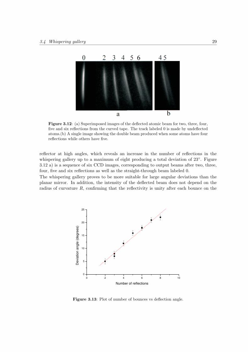
Figure 3.12: (a) Superimposed images of the deflected atomic beam for two, three, four,five and six reflections from the curved tape. The track labeled 0 is made by undeflectedatoms.(b) A single image showing the double beam produced when some atoms have fourreflections while others have five.
reflector at high angles, which reveals an increase in the number of reflections in thewhispering gallery up to a maximum of eight producing a total deviation of 23. Figure3.12 a) is a sequence of six CCD images, corresponding to output beams after two, three,four, five and six reflections as well as the straight-through beam labeled 0.
The whispering gallery proves to be more suitable for large angular deviations than theplanar mirror. In addition, the intensity of the deflected beam does not depend on theradius of curvature R, confirming that the reflectivity is unity after each bounce on the
0 2 4 6 8 10 0
5
10
15
20
25
Dev
iatio
n an
gle
(deg
rees
)
Number of reflections
Figure 3.13: Plot of number of bounces vs deflection angle.
30 Chapter 3: Whispering gallery mirror for atom beams
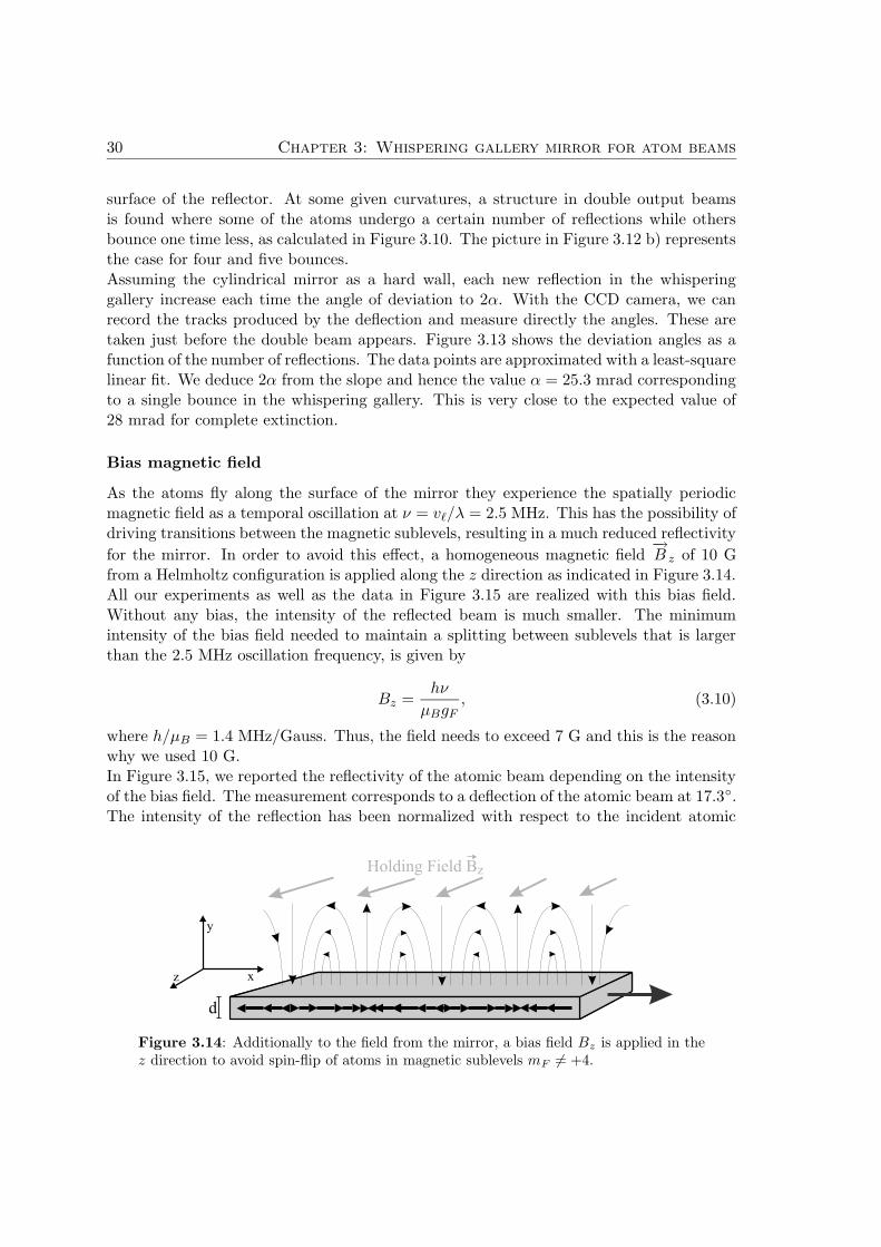
surface of the reflector. At some given curvatures, a structure in double output beamsis found where some of the atoms undergo a certain number of reflections while othersbounce one time less, as calculated in Figure 3.10. The picture in Figure 3.12 b) representsthe case for four and five bounces.Assuming the cylindrical mirror as a hard wall, each new reflection in the whisperinggallery increase each time the angle of deviation to 2α. With the CCD camera, we canrecord the tracks produced by the deflection and measure directly the angles. These aretaken just before the double beam appears. Figure 3.13 shows the deviation angles as afunction of the number of reflections. The data points are approximated with a least-squarelinear fit. We deduce 2α from the slope and hence the value α = 25.3 mrad correspondingto a single bounce in the whispering gallery. This is very close to the expected value of28 mrad for complete extinction.
Bias magnetic field
As the atoms fly along the surface of the mirror they experience the spatially periodicmagnetic field as a temporal oscillation at ν = v`/λ = 2.5 MHz. This has the possibility ofdriving transitions between the magnetic sublevels, resulting in a much reduced reflectivity
for the mirror. In order to avoid this effect, a homogeneous magnetic field−→B z of 10 G
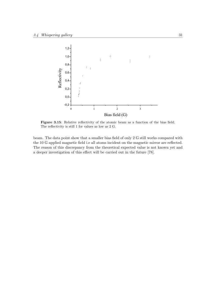
from a Helmholtz configuration is applied along the z direction as indicated in Figure 3.14.All our experiments as well as the data in Figure 3.15 are realized with this bias field.Without any bias, the intensity of the reflected beam is much smaller. The minimumintensity of the bias field needed to maintain a splitting between sublevels that is largerthan the 2.5 MHz oscillation frequency, is given by
Bz =hν
µBgF, (3.10)
where h/µB = 1.4 MHz/Gauss. Thus, the field needs to exceed 7 G and this is the reasonwhy we used 10 G.In Figure 3.15, we reported the reflectivity of the atomic beam depending on the intensityof the bias field. The measurement corresponds to a deflection of the atomic beam at 17.3.The intensity of the reflection has been normalized with respect to the incident atomic
Figure 3.14: Additionally to the field from the mirror, a bias field Bz is applied in thez direction to avoid spin-flip of atoms in magnetic sublevels mF 6= +4.
3.4 Whispering gallery 31
Figure 3.15: Relative reflectivity of the atomic beam as a function of the bias field.The reflectivity is still 1 for values as low as 2 G.
beam. The data point show that a smaller bias field of only 2 G still works compared withthe 10 G applied magnetic field i.e all atoms incident on the magnetic mirror are reflected.The reason of this discrepancy from the theoretical expected value is not known yet anda deeper investigation of this effect will be carried out in the future [78].

Chapter 4
A cold atomic beam from a
2D-MOT
In the last chapter, we demonstrated the possibility to deflect an atomic beam at largeangles by multiple reflections. However angles of incidence were restricted to the grazingincidence regime, well-known in x-rays optics. In this condition, we were not able toobserve the image formation of the Zeeman-slowed atomic beam at grazing incidence afterthe reflection onto the single reflector.To overcome this difficulty, atomic beams with large angles of incidence are required. Thisimplies either the development of new magnetic materials presenting higher magneticenergy at the surface of the mirror or to reduce the longitudinal velocity of atoms in theatomic beam. The second option has been chosen because videotapes have the advantageto keep easily any geometrical shape allowing us to design, if possible an abberation-freesystem. In the following chapter, a 2D-MOT is built as a source of our slow atomic beamwhich is first optically collimated and then optically pumped, for further experiments withmagnetic videotapes.
4.1 Principles of operation
4.1.1 3D Magneto-optical trapping
We consider first a gas of atoms irradiated in one dimension by two counterpropagating
laser beams with a wave number−→k . The laser frequency ωL is tuned just below the
atomic resonance ω0 (∆ = ωL − ω0 < 0 red detuning), which causes an atom movingwith a velocity −→v to absorb more light from the counterpropagating wave than from thecopropagating wave due to the Doppler shift. The laser exerts a radiation pressure onthe atom and leads to a damping of the atomic velocity [79].This basic idea has been extended to a large range of new applications to influence theatomic velocities and the phase space density.
In optical molasses, atoms are cooled but not confined because the damping force
33
34 Chapter 4: A cold atomic beam from a 2D-MOT
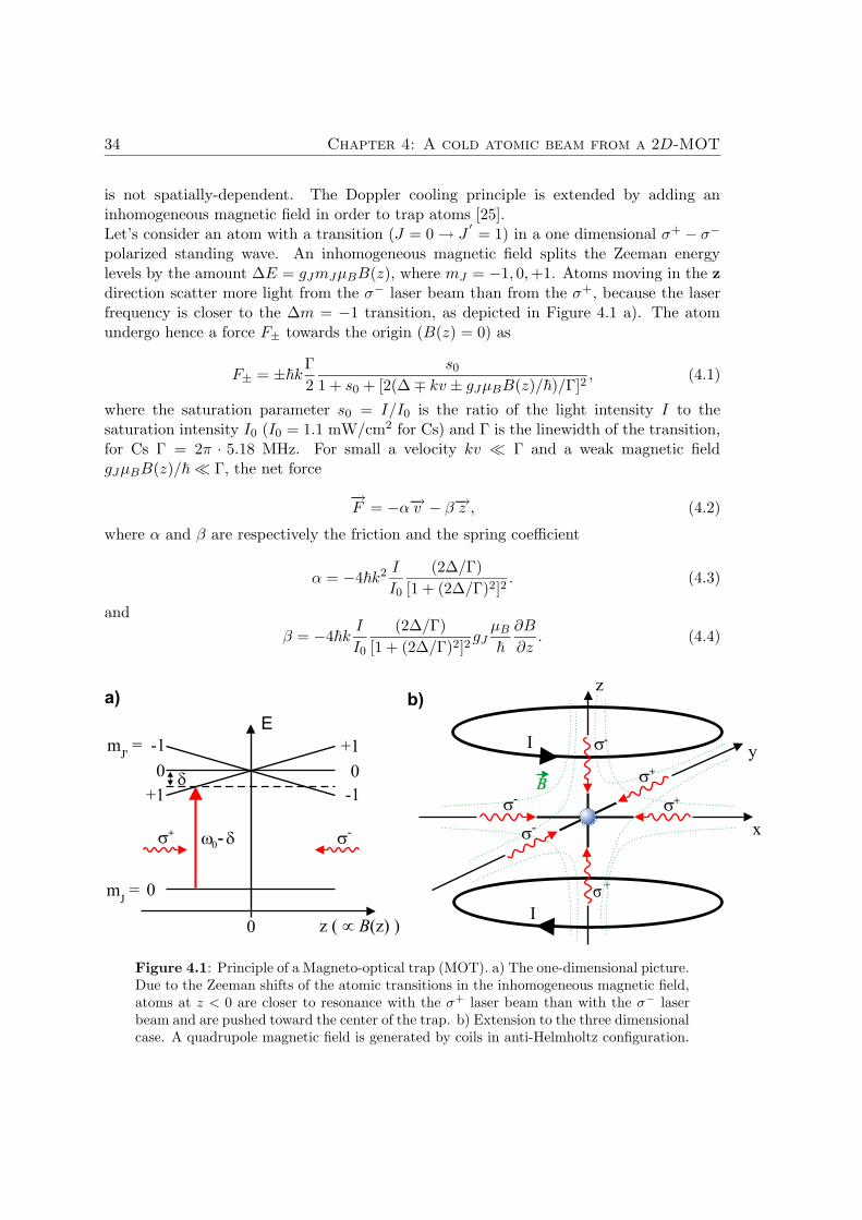
is not spatially-dependent. The Doppler cooling principle is extended by adding aninhomogeneous magnetic field in order to trap atoms [25].Let’s consider an atom with a transition (J = 0 → J
′
= 1) in a one dimensional σ+ − σ−
polarized standing wave. An inhomogeneous magnetic field splits the Zeeman energylevels by the amount ∆E = gJmJµBB(z), where mJ = −1, 0, +1. Atoms moving in the z
direction scatter more light from the σ− laser beam than from the σ+, because the laserfrequency is closer to the ∆m = −1 transition, as depicted in Figure 4.1 a). The atomundergo hence a force F± towards the origin (B(z) = 0) as
F± = ±~kΓ
2
s0
1 + s0 + [2(∆ ∓ kv ± gJµBB(z)/~)/Γ]2, (4.1)
where the saturation parameter s0 = I/I0 is the ratio of the light intensity I to thesaturation intensity I0 (I0 = 1.1 mW/cm2 for Cs) and Γ is the linewidth of the transition,for Cs Γ = 2π · 5.18 MHz. For small a velocity kv Γ and a weak magnetic fieldgJµBB(z)/~ Γ, the net force
−→F = −α−→v − β−→z , (4.2)
where α and β are respectively the friction and the spring coefficient
α = −4~k2 I
I0
(2∆/Γ)
[1 + (2∆/Γ)2]2. (4.3)
and
β = −4~kI
I0
(2∆/Γ)
[1 + (2∆/Γ)2]2gJ
µB
~
∂B
∂z. (4.4)
Figure 4.1: Principle of a Magneto-optical trap (MOT). a) The one-dimensional picture.Due to the Zeeman shifts of the atomic transitions in the inhomogeneous magnetic field,atoms at z < 0 are closer to resonance with the σ+ laser beam than with the σ− laserbeam and are pushed toward the center of the trap. b) Extension to the three dimensionalcase. A quadrupole magnetic field is generated by coils in anti-Helmholtz configuration.
4.1 Principles of operation 35
The damping force combined with the restoring force permits to cool and trap atoms inthe minimum B = 0 of a 3-dimensional magnetic field, schematically shown in Figure4.1 b). For further details see e.g. [80, 81, 82].
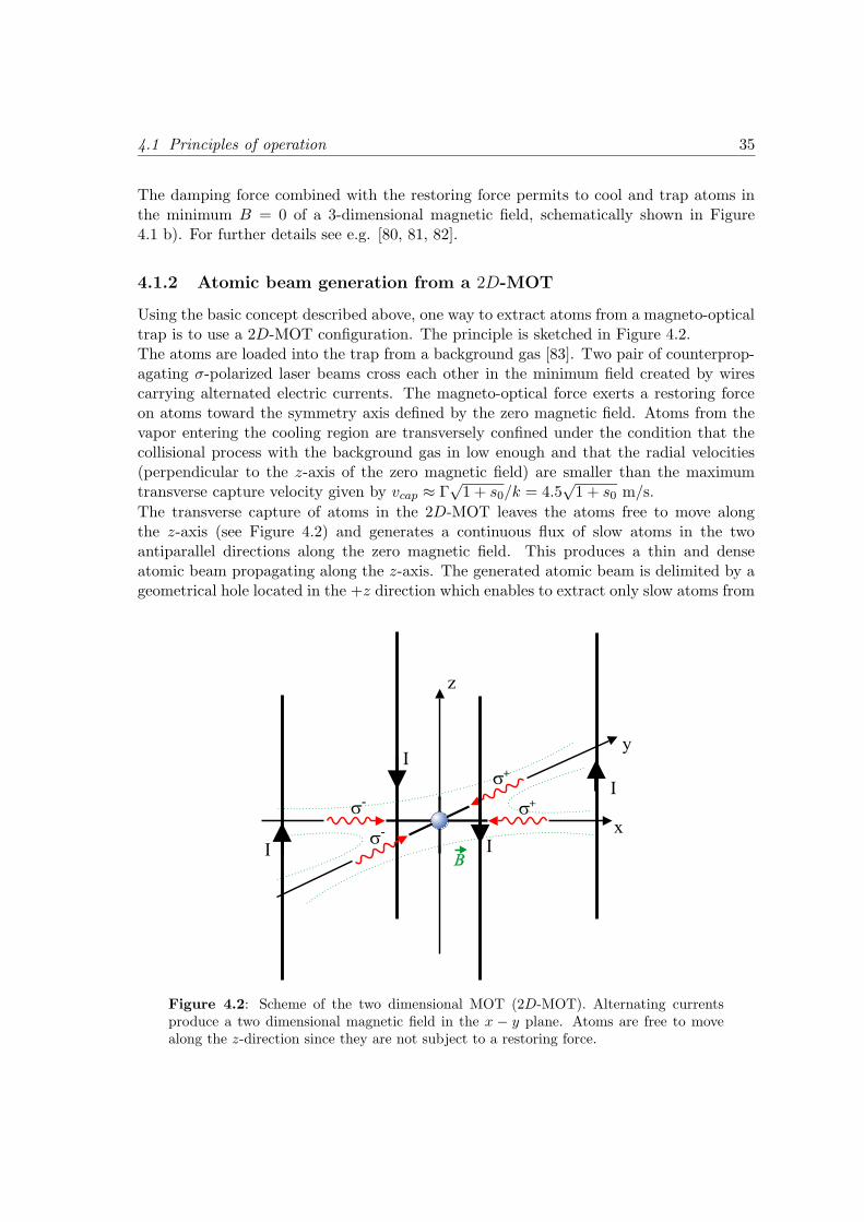
4.1.2 Atomic beam generation from a 2D-MOT
Using the basic concept described above, one way to extract atoms from a magneto-opticaltrap is to use a 2D-MOT configuration. The principle is sketched in Figure 4.2.The atoms are loaded into the trap from a background gas [83]. Two pair of counterprop-agating σ-polarized laser beams cross each other in the minimum field created by wirescarrying alternated electric currents. The magneto-optical force exerts a restoring forceon atoms toward the symmetry axis defined by the zero magnetic field. Atoms from thevapor entering the cooling region are transversely confined under the condition that thecollisional process with the background gas in low enough and that the radial velocities(perpendicular to the z-axis of the zero magnetic field) are smaller than the maximumtransverse capture velocity given by vcap ≈ Γ
√1 + s0/k = 4.5
√1 + s0 m/s.
The transverse capture of atoms in the 2D-MOT leaves the atoms free to move alongthe z-axis (see Figure 4.2) and generates a continuous flux of slow atoms in the twoantiparallel directions along the zero magnetic field. This produces a thin and denseatomic beam propagating along the z-axis. The generated atomic beam is delimited by ageometrical hole located in the +z direction which enables to extract only slow atoms from
I
x
y
z
B
s+
s+
s-
s-
I
I
I
Figure 4.2: Scheme of the two dimensional MOT (2D-MOT). Alternating currentsproduce a two dimensional magnetic field in the x − y plane. Atoms are free to movealong the z-direction since they are not subject to a restoring force.
36 Chapter 4: A cold atomic beam from a 2D-MOT
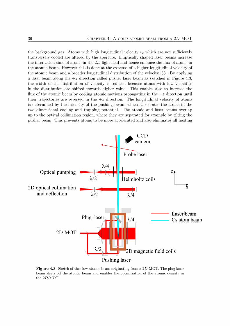
the background gas. Atoms with high longitudinal velocity v` which are not sufficientlytransversely cooled are filtered by the aperture. Elliptically shaped laser beams increasethe interaction time of atoms in the 2D light field and hence enhance the flux of atoms inthe atomic beam. However this is done at the expense of a higher longitudinal velocity ofthe atomic beam and a broader longitudinal distribution of the velocity [33]. By applyinga laser beam along the +z direction called pusher laser beam as sketched in Figure 4.3,the width of the distribution of velocity is reduced because atoms with low velocitiesin the distribution are shifted towards higher value. This enables also to increase theflux of the atomic beam by cooling atomic motions propagating in the −z direction untiltheir trajectories are reversed in the +z direction. The longitudinal velocity of atomsis determined by the intensity of the pushing beam, which accelerates the atoms in thetwo dimensional cooling and trapping potential. The atomic and laser beams overlapup to the optical collimation region, where they are separated for example by tilting thepusher beam. This prevents atoms to be more accelerated and also eliminates all heating
l/4
l/4
l/4
Laser beam
Cs Atom beam
l/2
l/2
l/2
2D optical collimationand deflection
2D-MOT
Optical pumping
Pushing laser
Plug laser
CCDcamera
Probe laser
Helmholtz coils
2D magnetic field coils
Laser beamCs atom beam
z
x
Figure 4.3: Sketch of the slow atomic beam originating from a 2D-MOT. The plug laserbeam shuts off the atomic beam and enables the optimization of the atomic density inthe 2D-MOT.
4.2 Experimental set-up 37
effects leading to a transverse spread of the atomic beam. In our setup the pushing beampolarization (σ+) and intensity (2.96 mW/cm2) was adjusted so that the atomic beamflux is maximum. In principle, reducing the intensity as well as changing the detuning ofthe pusher should increase the number of slow atoms in the beam as outlined in [26, 33].In order to obtain a narrow longitudinal distribution of velocity, an additional laser beampropagating in the −z direction can be applied [27]. With a different laser beam intensityand a separate detuning from the +z-axis propagating laser beam the longitudinal velocityof the atoms is cooled and can be controlled so that slow velocity can be obtained. Thiscan be however unsuitable in our experiments because it leads to a higher divergence ofthe atomic beam while a well collimated beam is desired.The divergence of the atomic beam is defined by the geometrical hole placed along the+z axis. It turns out that the pusher beam reduces the transverse spread of the atomicbeam. However the divergence of most of beams extracted from a 2D-MOT (from 30 to50 mrad) are still too large for realizing reasonable experiments with magnetic mirrors.To improve the experimental conditions, a transverse cooling stage described in detailsbelow is necessary to reduce the divergence but also to enhance the atomic density of theatomic beam.
4.2 Experimental set-up
4.2.1 Vacuum system
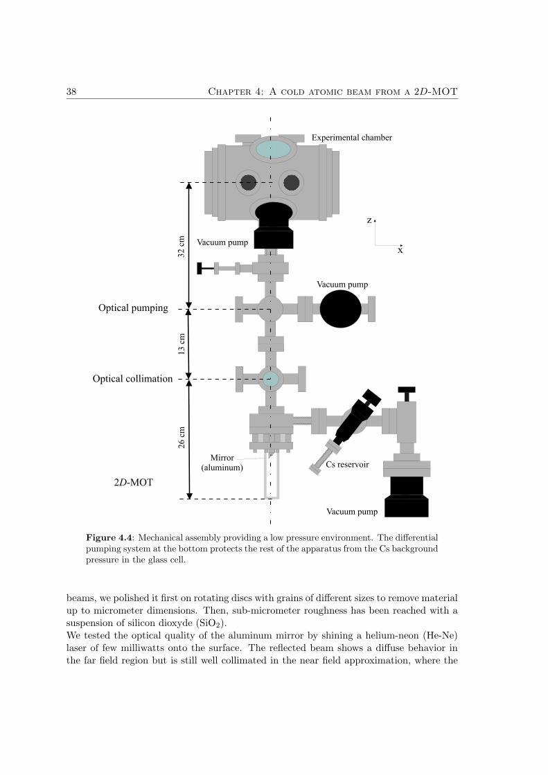
The vacuum chamber is based on stainless steel crosses connected to an experimentalchamber, as sketched in Figure 4.4. Two six-way crosses with a 35 mm inner diameter(CF 35) needed for optical transverse collimation and optical pumping are built along thevertical direction. They are separated at the top side from the experimental stage by avalve. A four way cross CF-35, which sustains a 70 l/s turbo-molecular pump and anelectrical feedthrough is attached with the upper cross. The viewports are anti-reflectioncoated windows at the 852.3 nm i.e. the wavelength of the Cs-D2 transition. The lowervacuum part carries an anti-reflection coated quartz glass cell with a dimension of (30 ×30 × 142) mm. It is related to the rest of the apparatus with an adapter consisting of acircular aluminum plate pressing strongly the base (∅ = 75 mm) of the glass cell by themean of an helicoflex seal onto a reduction flange CF-35/64. There, a hole is drilled onthe side, where a flexible bulk enables Cs atoms to reach directly the glass cell withoutaffecting the upper part of the vacuum system. In front of the atom reservoir, a 270 l/sturbo-molecular pump and a Bayard-Alpert ion gauge are positioned face to face at theends of the four-way cross.
Aluminum mirror
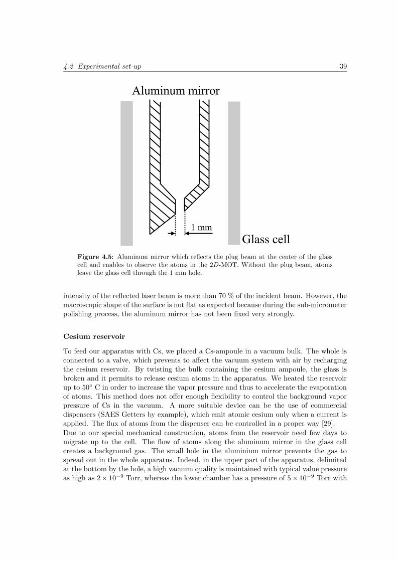
Extending in the glass cell as shown in Figure 4.5, a cylinder-trapezoidal shaped aluminummirror fixed onto a copper ring isolates the glass cell from the rest of the apparatus. Thehole in the mirror has a diameter of 1 mm, through which atoms from the 2D-MOT arefree to travel. To use the surface of the aluminum mirror as an optical reflector for laser
38 Chapter 4: A cold atomic beam from a 2D-MOT
26
cm32
cm13 c
m
Vacuum pump
Experimental chamber
Vacuum pump
Vacuum pump
Cs reservoirMirror
(aluminum)
2 -MOTD
Optical collimation
Optical pumping
z
x
Figure 4.4: Mechanical assembly providing a low pressure environment. The differentialpumping system at the bottom protects the rest of the apparatus from the Cs backgroundpressure in the glass cell.
beams, we polished it first on rotating discs with grains of different sizes to remove materialup to micrometer dimensions. Then, sub-micrometer roughness has been reached with asuspension of silicon dioxyde (SiO2).We tested the optical quality of the aluminum mirror by shining a helium-neon (He-Ne)laser of few milliwatts onto the surface. The reflected beam shows a diffuse behavior inthe far field region but is still well collimated in the near field approximation, where the
4.2 Experimental set-up 39
Glass cell
Aluminum mirror
1 mm
Figure 4.5: Aluminum mirror which reflects the plug beam at the center of the glasscell and enables to observe the atoms in the 2D-MOT. Without the plug beam, atomsleave the glass cell through the 1 mm hole.
intensity of the reflected laser beam is more than 70 % of the incident beam. However, themacroscopic shape of the surface is not flat as expected because during the sub-micrometerpolishing process, the aluminum mirror has not been fixed very strongly.
Cesium reservoir
To feed our apparatus with Cs, we placed a Cs-ampoule in a vacuum bulk. The whole isconnected to a valve, which prevents to affect the vacuum system with air by rechargingthe cesium reservoir. By twisting the bulk containing the cesium ampoule, the glass isbroken and it permits to release cesium atoms in the apparatus. We heated the reservoirup to 50 C in order to increase the vapor pressure and thus to accelerate the evaporationof atoms. This method does not offer enough flexibility to control the background vaporpressure of Cs in the vacuum. A more suitable device can be the use of commercialdispensers (SAES Getters by example), which emit atomic cesium only when a current isapplied. The flux of atoms from the dispenser can be controlled in a proper way [29].
Due to our special mechanical construction, atoms from the reservoir need few days tomigrate up to the cell. The flow of atoms along the aluminum mirror in the glass cellcreates a background gas. The small hole in the aluminium mirror prevents the gas tospread out in the whole apparatus. Indeed, in the upper part of the apparatus, delimitedat the bottom by the hole, a high vacuum quality is maintained with typical value pressureas high as 2× 10⁻⁹ Torr, whereas the lower chamber has a pressure of 5× 10⁻⁹ Torr with
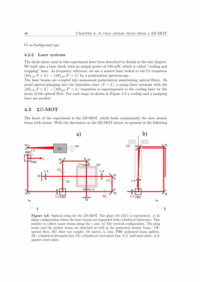
40 Chapter 4: A cold atomic beam from a 2D-MOT
Cs as background gas.
4.2.2 Laser systems
The diode lasers used in this experiment have been described in details in the last chapter.We built also a laser diode with an output power of 150 mW, which is called ”cooling andtrapping” laser. As frequency reference, we use a master laser locked to the Cs transition∣
∣ 6S1/2, F = 4⟩
→∣
∣ 6P3/2, F′ = 5
⟩
by a polarization spectroscopy .The laser beams are coupled into monomode polarization maintaining optical fibers. Toavoid optical pumping into the hyperfine state |F = 3 〉, a pump laser resonant with the∣
∣ 6S1/2, F = 3⟩
→∣
∣ 6P3/2, F′ = 4
⟩
transition is superimposed to the cooling laser by themean of the optical fiber. For each stage as shown in Figure 4.3 a cooling and a pumpinglaser are needed.
4.3 2D-MOT
The heart of the experiment is the 2D-MOT, which feeds continuously the slow atomicbeam with atoms. With the discussion on the 2D-MOT above, we present in the following
AOM
GC
GC
l/2
l/2 l/2
l/4
l/4
l/4
M
M
M
M M
M
MM
M
M
PBSz
CL
L
XL
XL
CL
PBS PBS
OCM
a) b)
l/4
l/4
OF
y z
x x
Figure 4.6: Optical setup for the 2D-MOT. The glass cell (GC) is represented. a) Inplane configuration where the laser beams are expanded with cylindrical telescopes. Thisenables to collect many atoms along the z axis. b) The vertical configuration. The plugbeam and the pusher beam are sketched as well as the generated atomic beam. OF:optical fiber, OC: fiber out coupler, M: mirror, L: lens, PBS: polarized beam splitter,XL: cylindrical divergent lens, CL: cylindrical convergent lens, λ/2: half-wave plate, λ/4:quarter-wave plate.
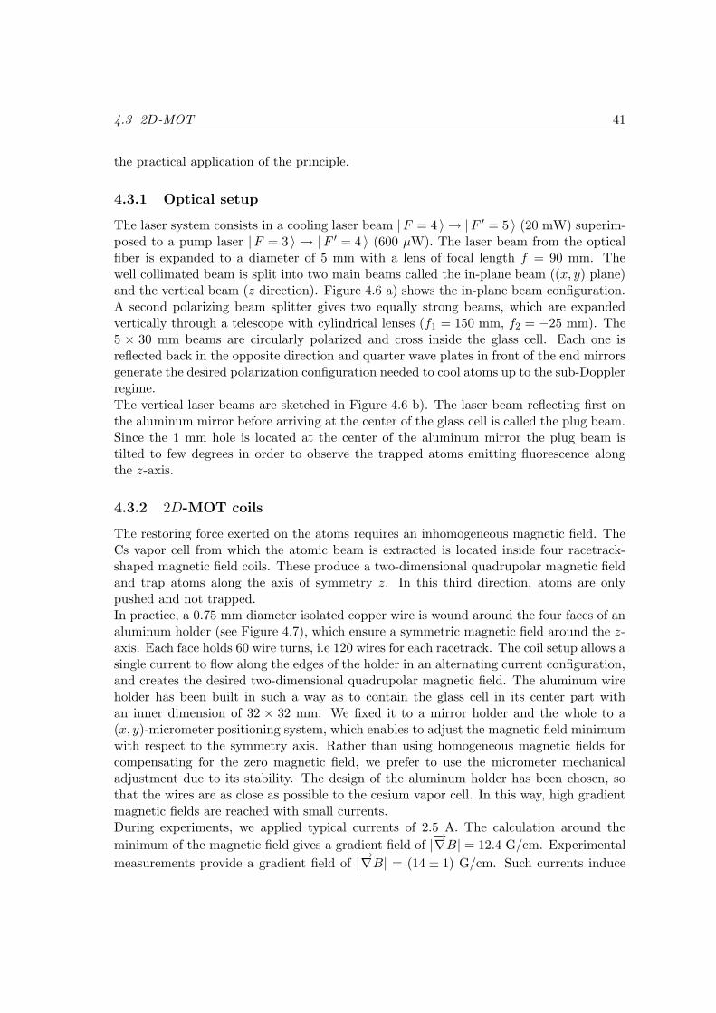
4.3 2D-MOT 41
the practical application of the principle.
4.3.1 Optical setup
The laser system consists in a cooling laser beam |F = 4 〉 → |F ′ = 5 〉 (20 mW) superim-posed to a pump laser |F = 3 〉 → |F ′ = 4 〉 (600 µW). The laser beam from the opticalfiber is expanded to a diameter of 5 mm with a lens of focal length f = 90 mm. Thewell collimated beam is split into two main beams called the in-plane beam ((x, y) plane)and the vertical beam (z direction). Figure 4.6 a) shows the in-plane beam configuration.A second polarizing beam splitter gives two equally strong beams, which are expandedvertically through a telescope with cylindrical lenses (f1 = 150 mm, f2 = −25 mm). The5 × 30 mm beams are circularly polarized and cross inside the glass cell. Each one isreflected back in the opposite direction and quarter wave plates in front of the end mirrorsgenerate the desired polarization configuration needed to cool atoms up to the sub-Dopplerregime.
The vertical laser beams are sketched in Figure 4.6 b). The laser beam reflecting first onthe aluminum mirror before arriving at the center of the glass cell is called the plug beam.Since the 1 mm hole is located at the center of the aluminum mirror the plug beam istilted to few degrees in order to observe the trapped atoms emitting fluorescence alongthe z-axis.
4.3.2 2D-MOT coils
The restoring force exerted on the atoms requires an inhomogeneous magnetic field. TheCs vapor cell from which the atomic beam is extracted is located inside four racetrack-shaped magnetic field coils. These produce a two-dimensional quadrupolar magnetic fieldand trap atoms along the axis of symmetry z. In this third direction, atoms are onlypushed and not trapped.In practice, a 0.75 mm diameter isolated copper wire is wound around the four faces of analuminum holder (see Figure 4.7), which ensure a symmetric magnetic field around the z-axis. Each face holds 60 wire turns, i.e 120 wires for each racetrack. The coil setup allows asingle current to flow along the edges of the holder in an alternating current configuration,and creates the desired two-dimensional quadrupolar magnetic field. The aluminum wireholder has been built in such a way as to contain the glass cell in its center part withan inner dimension of 32 × 32 mm. We fixed it to a mirror holder and the whole to a(x, y)-micrometer positioning system, which enables to adjust the magnetic field minimumwith respect to the symmetry axis. Rather than using homogeneous magnetic fields forcompensating for the zero magnetic field, we prefer to use the micrometer mechanicaladjustment due to its stability. The design of the aluminum holder has been chosen, sothat the wires are as close as possible to the cesium vapor cell. In this way, high gradientmagnetic fields are reached with small currents.During experiments, we applied typical currents of 2.5 A. The calculation around the
minimum of the magnetic field gives a gradient field of |−→∇B| = 12.4 G/cm. Experimental
measurements provide a gradient field of |−→∇B| = (14 ± 1) G/cm. Such currents induce
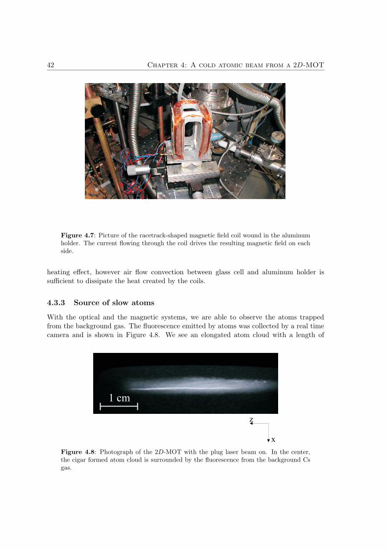
42 Chapter 4: A cold atomic beam from a 2D-MOT
Figure 4.7: Picture of the racetrack-shaped magnetic field coil wound in the aluminumholder. The current flowing through the coil drives the resulting magnetic field on eachside.
heating effect, however air flow convection between glass cell and aluminum holder issufficient to dissipate the heat created by the coils.
4.3.3 Source of slow atoms
With the optical and the magnetic systems, we are able to observe the atoms trappedfrom the background gas. The fluorescence emitted by atoms was collected by a real timecamera and is shown in Figure 4.8. We see an elongated atom cloud with a length of
Figure 4.8: Photograph of the 2D-MOT with the plug laser beam on. In the center,the cigar formed atom cloud is surrounded by the fluorescence from the background Csgas.
4.4 Optical transverse collimation 43
30 mm in the potential minimum created by the elliptically shaped laser light and thetwo-dimensional magnetic field. The maximum number of trapped atoms is obtained at alaser detuning δL = −2Γ, with Γ the Cs natural linewidth and a magnetic field gradientof 12.4 G/cm.The fluorescence intensity increases with the background atom density and then saturates.For very high densities the MOT is destroyed due to the collisions.By blocking the plug beam, atoms are forced out of the trap so that slow atoms propagatethrough the 1 mm hole in the aluminum mirror and form an atomic beam. Withoutthe plug beam, we could still distinguish atoms in the 2D-MOT potential due to theradiation pressure of the pushing beam. To optimize the flux of atoms we easily adjustthe MOT position by moving the magnetic field null point of the anti-Helmholtz coils.We detected the atoms by shining a laser beam of few mW placed 15 cm above the holeand perpendicular to the atomic beam. The emitted photons are detected by a photo-multiplier tube (PMT). We estimated roughly the atomic beam diameter and found typicaldiameter of ∼ 7 − 8 mm. During the propagation the atomic beam undergoes a constantexpansion and the reflected atoms cannot be separated from the incident atomic beam.To avoid such complications, we reduce the atomic beam diameter in the experimentalchamber by decreasing its divergence with an optical transverse collimation. This leadsalso to a higher number of reflected atoms.
4.4 Optical transverse collimation
4.4.1 Principle
The expansion of our cold atomic beam along the 64 cm propagation distance turns out tobe problematic for reflecting atoms onto magnetic mirrors. Indeed, atoms leaving the 1 mmdiameter hole from the glass cell are subject to a transverse velocity selection through the8 mm hole of the magnetic shielding located 29 cm downstream. These physical aperturesdelimit the atomic beam width. A calculation leads to a divergence of 15.5 mrad andthus to a beam diameter of 18.9 mm in the probe region. A transverse collimation withan optical molasses, 49 cm below, is realized which reduces the atomic beam diameter to3.7 mm in the two dimensional collimation stage. This is realized by the same methoddescribed in the Zeeman-slower experiment, where atoms in a polarized standing wave aretransversely sub-Doppler cooled in order to reduce strongly the divergence of the atomicbeam.
4.4.2 Optical setup
The optical molasses is realized with a cooling and a pump laser in a retro-reflectingconfiguration. The linear polarized laser beam is expanded up to 10 mm in diameter witha lens of focal length f = 120 mm. A half wave plate turns the polarization direction to45 relatively to the atomic beam axis. In a single laser beam arrangement as sketched inFigure 4.9, two pairs of counterpropagating beams cross at the center of a six-way cross.A quarter wave plate, mounted before retroreflection on the last mirror, rotates the laser
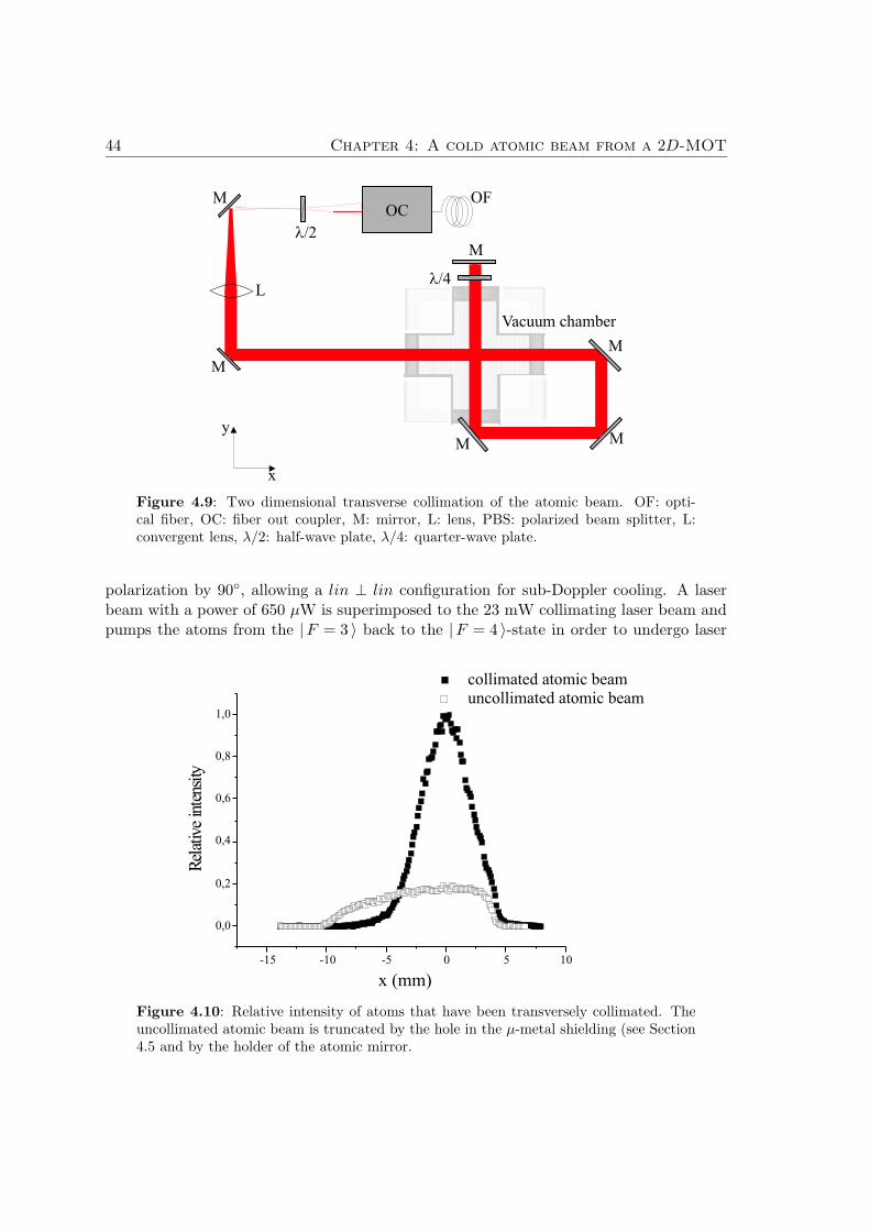
44 Chapter 4: A cold atomic beam from a 2D-MOT
AOM
l/2
l/4
M
L
OCOF
M
Vacuum chamber
M
M
M
M
y
x
Figure 4.9: Two dimensional transverse collimation of the atomic beam. OF: opti-cal fiber, OC: fiber out coupler, M: mirror, L: lens, PBS: polarized beam splitter, L:convergent lens, λ/2: half-wave plate, λ/4: quarter-wave plate.
polarization by 90, allowing a lin ⊥ lin configuration for sub-Doppler cooling. A laserbeam with a power of 650 µW is superimposed to the 23 mW collimating laser beam andpumps the atoms from the |F = 3 〉 back to the |F = 4 〉-state in order to undergo laser
Figure 4.10: Relative intensity of atoms that have been transversely collimated. Theuncollimated atomic beam is truncated by the hole in the µ-metal shielding (see Section4.5 and by the holder of the atomic mirror.
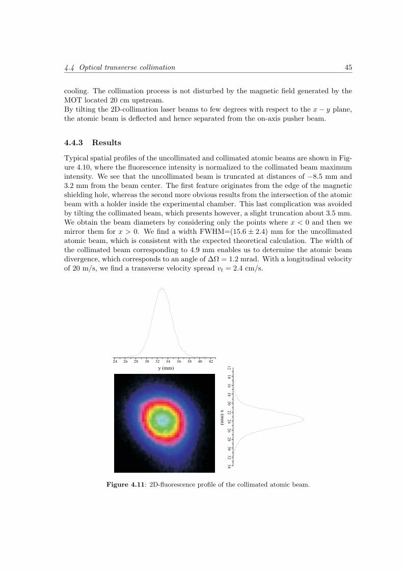
4.4 Optical transverse collimation 45
cooling. The collimation process is not disturbed by the magnetic field generated by theMOT located 20 cm upstream.By tilting the 2D-collimation laser beams to few degrees with respect to the x − y plane,the atomic beam is deflected and hence separated from the on-axis pusher beam.
4.4.3 Results
Typical spatial profiles of the uncollimated and collimated atomic beams are shown in Fig-ure 4.10, where the fluorescence intensity is normalized to the collimated beam maximumintensity. We see that the uncollimated beam is truncated at distances of −8.5 mm and3.2 mm from the beam center. The first feature originates from the edge of the magneticshielding hole, whereas the second more obvious results from the intersection of the atomicbeam with a holder inside the experimental chamber. This last complication was avoidedby tilting the collimated beam, which presents however, a slight truncation about 3.5 mm.We obtain the beam diameters by considering only the points where x < 0 and then wemirror them for x > 0. We find a width FWHM=(15.6 ± 2.4) mm for the uncollimatedatomic beam, which is consistent with the expected theoretical calculation. The width ofthe collimated beam corresponding to 4.9 mm enables us to determine the atomic beamdivergence, which corresponds to an angle of ∆Ω = 1.2 mrad. With a longitudinal velocityof 20 m/s, we find a transverse velocity spread vt = 2.4 cm/s.
Figure 4.11: 2D-fluorescence profile of the collimated atomic beam.
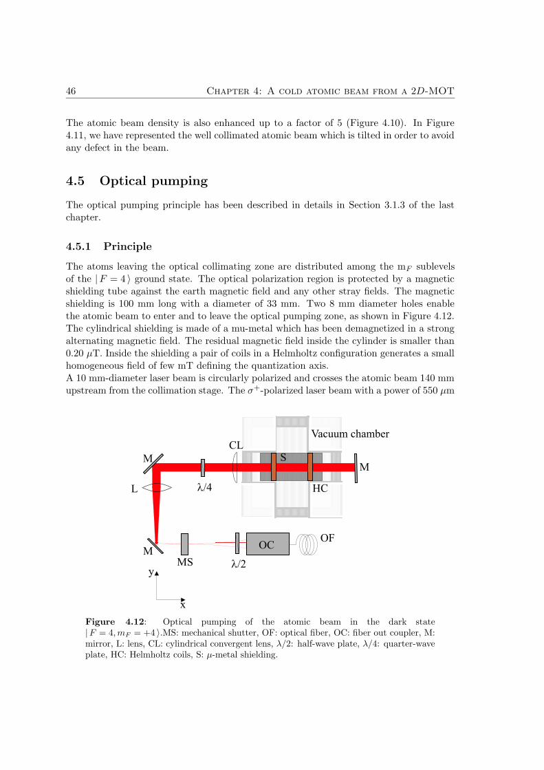
46 Chapter 4: A cold atomic beam from a 2D-MOT
The atomic beam density is also enhanced up to a factor of 5 (Figure 4.10). In Figure4.11, we have represented the well collimated atomic beam which is tilted in order to avoidany defect in the beam.
4.5 Optical pumping
The optical pumping principle has been described in details in Section 3.1.3 of the lastchapter.
4.5.1 Principle
The atoms leaving the optical collimating zone are distributed among the mF sublevelsof the |F = 4 〉 ground state. The optical polarization region is protected by a magneticshielding tube against the earth magnetic field and any other stray fields. The magneticshielding is 100 mm long with a diameter of 33 mm. Two 8 mm diameter holes enablethe atomic beam to enter and to leave the optical pumping zone, as shown in Figure 4.12.The cylindrical shielding is made of a mu-metal which has been demagnetized in a strongalternating magnetic field. The residual magnetic field inside the cylinder is smaller than0.20 µT. Inside the shielding a pair of coils in a Helmholtz configuration generates a smallhomogeneous field of few mT defining the quantization axis.A 10 mm-diameter laser beam is circularly polarized and crosses the atomic beam 140 mmupstream from the collimation stage. The σ+-polarized laser beam with a power of 550 µm
Figure 4.12: Optical pumping of the atomic beam in the dark state|F = 4,mF = +4 〉.MS: mechanical shutter, OF: optical fiber, OC: fiber out coupler, M:mirror, L: lens, CL: cylindrical convergent lens, λ/2: half-wave plate, λ/4: quarter-waveplate, HC: Helmholtz coils, S: µ-metal shielding.
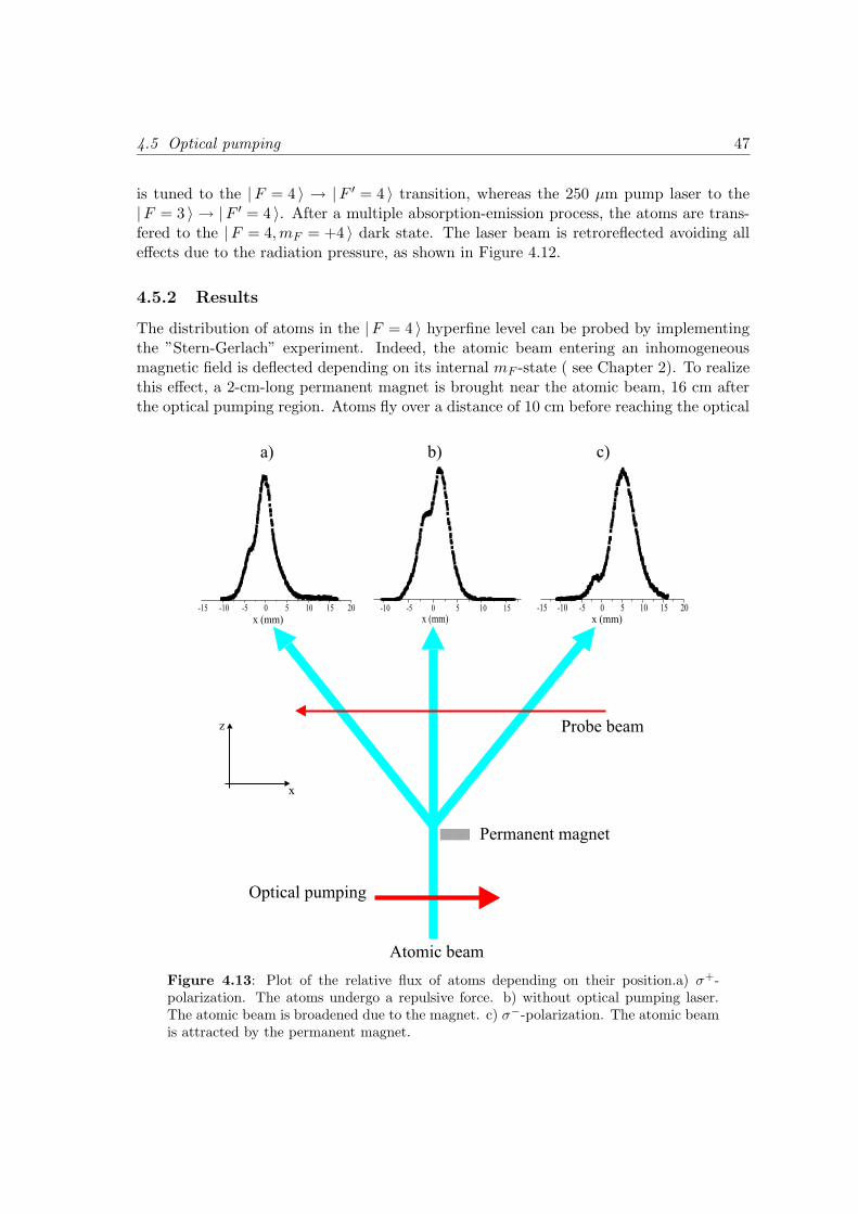
4.5 Optical pumping 47
is tuned to the |F = 4 〉 → |F ′ = 4 〉 transition, whereas the 250 µm pump laser to the|F = 3 〉 → |F ′ = 4 〉. After a multiple absorption-emission process, the atoms are trans-fered to the |F = 4, mF = +4 〉 dark state. The laser beam is retroreflected avoiding alleffects due to the radiation pressure, as shown in Figure 4.12.
4.5.2 Results
The distribution of atoms in the |F = 4 〉 hyperfine level can be probed by implementingthe ”Stern-Gerlach” experiment. Indeed, the atomic beam entering an inhomogeneousmagnetic field is deflected depending on its internal mF -state ( see Chapter 2). To realizethis effect, a 2-cm-long permanent magnet is brought near the atomic beam, 16 cm afterthe optical pumping region. Atoms fly over a distance of 10 cm before reaching the optical
-10 -5 0 5 10 15
x (mm)-15 -10 -5 0 5 10 15 20
x (mm)-15 -10 -5 0 5 10 15 20
x (mm)
Optical pumping
Atomic beam
Permanent magnet
Probe beam
x
z
a) b) c)
Figure 4.13: Plot of the relative flux of atoms depending on their position.a) σ+-polarization. The atoms undergo a repulsive force. b) without optical pumping laser.The atomic beam is broadened due to the magnet. c) σ−-polarization. The atomic beamis attracted by the permanent magnet.
48 Chapter 4: A cold atomic beam from a 2D-MOT
detection region.Figure 4.13 b) presents the atomic distribution of the magnetic states after leaving thecollimating and deflecting region. In this case, the optical pumping laser beam is shutdown. The atomic beam is broadened and all mF -states are situated between the extremestates mF = +4 and mF = −4. Each mF -level could not be resolved due to the smallflight distance between the permanent magnet and the probe laser.We applied the circularly polarized laser beam and the small magnetic field created by theHelmholtz coils inside the magnetic shielding. We observed an optical pumping of atomseither in mF > 0 states or in mF < 0 depending on the position of the quarter wave plate.The polarization of the atomic beam is shown in Figure 4.13 a) and Figure 4.13 c) forthe two positions of the quarter-half plate leading to σ+ and σ− laser polarization. Inprinciple in the σ− case, most of atoms are pumped in the mF < 0 state while with the σ+
most of them occupy the mF > 0 states. Contrary to the optical polarization realized inthe Zeeman-slower experiment, in this setup the low resolution does not allow to observeeach mF sub-states and this is essentially due to the small flight distance of atoms betweenthe optical pumping zone and the detection region. However, experiments with magneticvideotapes enable us to optimize the reflected atomic beam so that most of the atoms arepumped in the |F = 4, mF = +4 〉 state.
4.6 Atomic beam characterization
As seen in Chapter 2, the longitudinal velocity gives the maximal reflection angle for amagnetic mirror, the degree of monochromacity of the atomic beam is described by thelongitudinal velocity distribution. The atomic beam profile is measured with a laser-induced fluorescence technique. Crossing the atomic beam at an angle of (116.6 ± 0.5)
with respect to the direction of propagation, a CCD-camera collects the scattered photons(|F = 4 〉 → |F ′ = 5 〉) from a weak probe laser (∅ ' 5 mm), which intensity (1.5 mW) ischosen so that the fluorescence intensity is sufficient observable.
4.6.1 Gravitation effect
In our study, we neglect all gravitational effects and the particles, starting on an axisin the 2D-MOT, travel on straight line trajectories. For example, an atom with initialvelocity v`i moving in an atomic beam undergo a constant gravitational deceleration −→gover a height h. The final velocity v`f is given by v`f =
√
v2`i − 2gh. For v`i = 20 m/s and
h = 1 m, we find v`f = 19.5 m/s. In this work, the experimental conditions are alwayssatisfied by the inequality
√2gh v`i so that the initial velocity defines the velocity of
the atomic beam. Therefore, the analysis of magnetic systems for reflection is realized byconsidering the motion of an atom equivalent to that of a light ray. The path l followedby an atom is simply l = v`t, where t is the time. However for very cold atoms, thecontribution of the gravity is non-negligible and has to be taken into account [17].
4.6 Atomic beam characterization 49
4.6.2 Longitudinal velocity distribution
The velocity of the atomic beam is first measured with a Doppler-induced fluorescencetechnique. The probe beam is frequency-scanned across the atomic beam transi-tion (|F = 4 〉 → |F ′ = 5 〉) and induces a maximum fluorescence for a detuning of(9.6 ± 1.4) MHz corresponding to a longitudinal velocity (v` = 18.7 ± 2.7) m/s. Indeed,the determination of the distribution is limited by the broadened natural linewidth γ of theCs atomic excited state [22] and it follows a resolution limit of ∆v` = λ · γ/ cos θ
√1 + s.
With λ = 852.3 nm, γ = 5.2 MHz, θ = 26 and s = I/I0, I = 25.5 mW/cm2 andI0=1.1 mW/cm2, we find ∆v` = 49.7 m/s.We investigate deeper the velocity distribution by a time-of-flight (TOF) measurement[20]. A laser light sheet realized by focusing the laser with a cylindrical lens (120 µW)and resonant with the |F = 4 〉 → |F ′ = 4 〉 transition is focused on the atomic beamand pumps atoms in the |F = 3 〉 ground state. The light beam is cut off periodically(square signal, period T=1.8 Hz) by a fast mechanical shutter. After a flight distance of40 cm, a laser beam probes the transition |F = 4 〉 → |F ′ = 5 〉 of the atomic beam. Aphotomultiplier collects the scattered photons.The time reference signal is given by the driver signal of the mechanical shutter. Whenthe pump beam is turned off and on, we visualize the time dependent decreasing andincreasing fluorescence signal, which informs about the arrival time of atoms in the probelaser beam. The signal is averaged on a long time scale so that a measurement canbe taken. Otherwise the signal disappear totaly because the dominant contribution isthe stray light from the laser beam. Although a weak TOF signal, we could extractinformation on the longitudinal distribution of velocity. We find a velocity spread∆v` = 2.4 m/s centered on the mean velocity v` = (21.5 ± 2) m/s.

Chapter 5
Atomic focusing by a curved
magnetic reflector
In the previous chapter we described our new source of slow atoms enabling us to generatea well collimated atomic beam optically pumped in the states mF = +4 which is repulsivein an inhomogeneous magnetic field. The atoms impinging on a curved magnetic reflectorare incident at larger angles compared with those presented in Chapter 3. This offersa new possibility for focusing the atomic beam and hence to study the image-formationproperties of a curved videotape. This opens new perspectives in atomic beam imagingwith reflective optics.
5.1 Principle
5.1.1 Focusing with a spherical mirror
The main goal of this experiment is to focus an atomic beam by reflections on a curvedreflector as sketched in Figure 5.1. Atoms moving towards a spherical magnetic mirrorexperience the magnetic force µ0kB0e
−ky which causes them to be concentrated to acommon point called f (Figure 5.1 a)). The image formation of an atomic beam incidentat an angle α on a cylindrical reflector with a radius of curvature R is given by Equation(A.17) in Appendix A as
f =R
2sin α, (5.1)
where α is the angle of incidence defined by the central ray of the atomic beam andthe curved reflector. The focus point f0 = R/2 corresponds to the focus of atoms atnear normal incidence angles, which can be reached either with higher magnetic barrierintensity B0 or with smaller longitudinal velocity v`. The focus f is well defined providingthat the chord D subtended by the angle β at the curvature center of the spherical mirroris much larger than the chord d defined by the diameter of the atomic beam arriving ontothe surface of the magnetic mirror shown in Figure 5.1 b), i.e
51
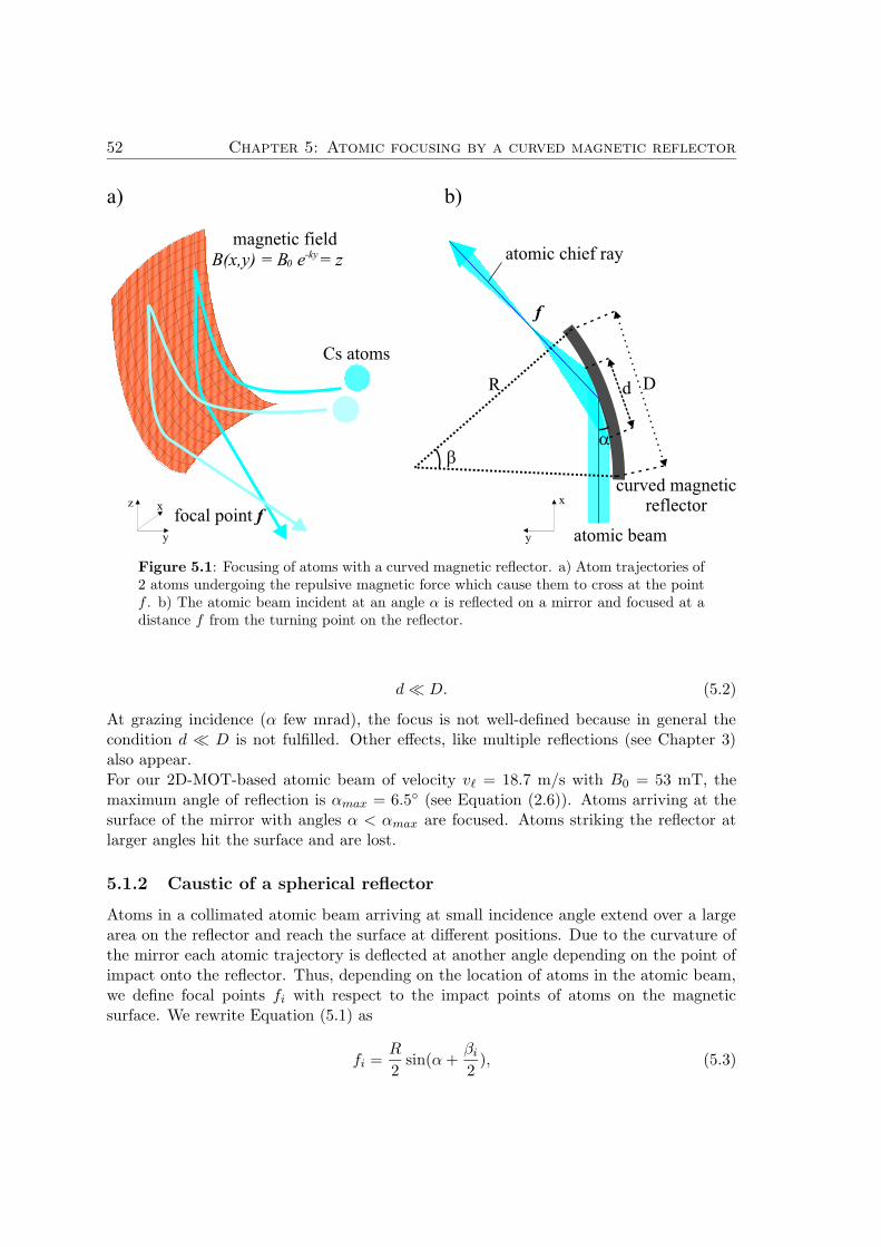
52 Chapter 5: Atomic focusing by a curved magnetic reflector
curved magneticreflector
atomic chief ray
atomic beam
Cs atoms
magnetic field
a) b)
B(x,y) = B e = z0-ky
DR
ba
focal point f
f
y
x
y
z x
d
Figure 5.1: Focusing of atoms with a curved magnetic reflector. a) Atom trajectories of2 atoms undergoing the repulsive magnetic force which cause them to cross at the pointf . b) The atomic beam incident at an angle α is reflected on a mirror and focused at adistance f from the turning point on the reflector.
d D. (5.2)
At grazing incidence (α few mrad), the focus is not well-defined because in general thecondition d D is not fulfilled. Other effects, like multiple reflections (see Chapter 3)also appear.For our 2D-MOT-based atomic beam of velocity v` = 18.7 m/s with B0 = 53 mT, themaximum angle of reflection is αmax = 6.5 (see Equation (2.6)). Atoms arriving at thesurface of the mirror with angles α < αmax are focused. Atoms striking the reflector atlarger angles hit the surface and are lost.
5.1.2 Caustic of a spherical reflector
Atoms in a collimated atomic beam arriving at small incidence angle extend over a largearea on the reflector and reach the surface at different positions. Due to the curvature ofthe mirror each atomic trajectory is deflected at another angle depending on the point ofimpact onto the reflector. Thus, depending on the location of atoms in the atomic beam,we define focal points fi with respect to the impact points of atoms on the magneticsurface. We rewrite Equation (5.1) as
fi =R
2sin(α +
βi
2), (5.3)
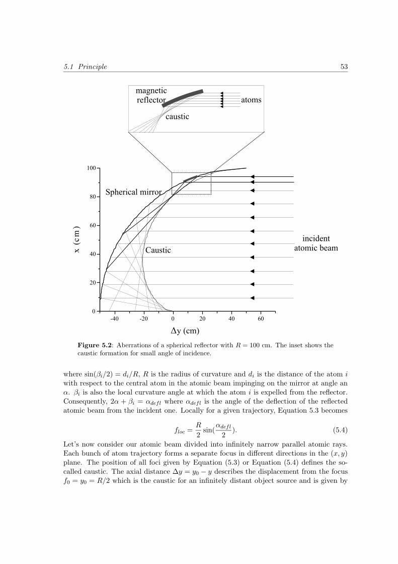
5.1 Principle 53
Figure 5.2: Aberrations of a spherical reflector with R = 100 cm. The inset shows thecaustic formation for small angle of incidence.
where sin(βi/2) = di/R, R is the radius of curvature and di is the distance of the atom iwith respect to the central atom in the atomic beam impinging on the mirror at angle anα. βi is also the local curvature angle at which the atom i is expelled from the reflector.Consequently, 2α + βi = αdefl where αdefl is the angle of the deflection of the reflectedatomic beam from the incident one. Locally for a given trajectory, Equation 5.3 becomes
floc =R
2sin(
αdefl
2). (5.4)
Let’s now consider our atomic beam divided into infinitely narrow parallel atomic rays.Each bunch of atom trajectory forms a separate focus in different directions in the (x, y)plane. The position of all foci given by Equation (5.3) or Equation (5.4) defines the so-called caustic. The axial distance ∆y = y0 − y describes the displacement from the focusf0 = y0 = R/2 which is the caustic for an infinitely distant object source and is given by
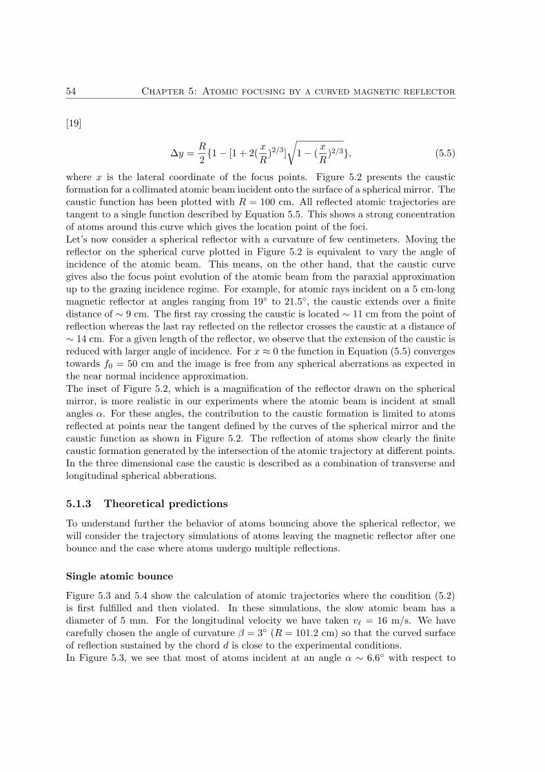
54 Chapter 5: Atomic focusing by a curved magnetic reflector
[19]
∆y =R
21 − [1 + 2(
x
R)2/3]
√
1 − (x
R)2/3, (5.5)
where x is the lateral coordinate of the focus points. Figure 5.2 presents the causticformation for a collimated atomic beam incident onto the surface of a spherical mirror. Thecaustic function has been plotted with R = 100 cm. All reflected atomic trajectories aretangent to a single function described by Equation 5.5. This shows a strong concentrationof atoms around this curve which gives the location point of the foci.
Let’s now consider a spherical reflector with a curvature of few centimeters. Moving thereflector on the spherical curve plotted in Figure 5.2 is equivalent to vary the angle ofincidence of the atomic beam. This means, on the other hand, that the caustic curvegives also the focus point evolution of the atomic beam from the paraxial approximationup to the grazing incidence regime. For example, for atomic rays incident on a 5 cm-longmagnetic reflector at angles ranging from 19 to 21.5, the caustic extends over a finitedistance of ∼ 9 cm. The first ray crossing the caustic is located ∼ 11 cm from the point ofreflection whereas the last ray reflected on the reflector crosses the caustic at a distance of∼ 14 cm. For a given length of the reflector, we observe that the extension of the caustic isreduced with larger angle of incidence. For x ≈ 0 the function in Equation (5.5) convergestowards f0 = 50 cm and the image is free from any spherical aberrations as expected inthe near normal incidence approximation.
The inset of Figure 5.2, which is a magnification of the reflector drawn on the sphericalmirror, is more realistic in our experiments where the atomic beam is incident at smallangles α. For these angles, the contribution to the caustic formation is limited to atomsreflected at points near the tangent defined by the curves of the spherical mirror and thecaustic function as shown in Figure 5.2. The reflection of atoms show clearly the finitecaustic formation generated by the intersection of the atomic trajectory at different points.In the three dimensional case the caustic is described as a combination of transverse andlongitudinal spherical abberations.
5.1.3 Theoretical predictions
To understand further the behavior of atoms bouncing above the spherical reflector, wewill consider the trajectory simulations of atoms leaving the magnetic reflector after onebounce and the case where atoms undergo multiple reflections.
Single atomic bounce
Figure 5.3 and 5.4 show the calculation of atomic trajectories where the condition (5.2)is first fulfilled and then violated. In these simulations, the slow atomic beam has adiameter of 5 mm. For the longitudinal velocity we have taken v` = 16 m/s. We havecarefully chosen the angle of curvature β = 3 (R = 101.2 cm) so that the curved surfaceof reflection sustained by the chord d is close to the experimental conditions.In Figure 5.3, we see that most of atoms incident at an angle α ∼ 6.6 with respect to
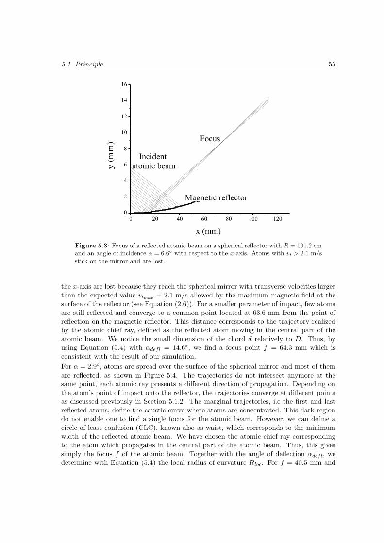
5.1 Principle 55
Figure 5.3: Focus of a reflected atomic beam on a spherical reflector with R = 101.2 cmand an angle of incidence α = 6.6 with respect to the x-axis. Atoms with vt > 2.1 m/sstick on the mirror and are lost.
the x-axis are lost because they reach the spherical mirror with transverse velocities largerthan the expected value vtmax
= 2.1 m/s allowed by the maximum magnetic field at thesurface of the reflector (see Equation (2.6)). For a smaller parameter of impact, few atomsare still reflected and converge to a common point located at 63.6 mm from the point ofreflection on the magnetic reflector. This distance corresponds to the trajectory realizedby the atomic chief ray, defined as the reflected atom moving in the central part of theatomic beam. We notice the small dimension of the chord d relatively to D. Thus, byusing Equation (5.4) with αdefl = 14.6, we find a focus point f = 64.3 mm which isconsistent with the result of our simulation.
For α = 2.9, atoms are spread over the surface of the spherical mirror and most of themare reflected, as shown in Figure 5.4. The trajectories do not intersect anymore at thesame point, each atomic ray presents a different direction of propagation. Depending onthe atom’s point of impact onto the reflector, the trajectories converge at different pointsas discussed previously in Section 5.1.2. The marginal trajectories, i.e the first and lastreflected atoms, define the caustic curve where atoms are concentrated. This dark regiondo not enable one to find a single focus for the atomic beam. However, we can define acircle of least confusion (CLC), known also as waist, which corresponds to the minimumwidth of the reflected atomic beam. We have chosen the atomic chief ray correspondingto the atom which propagates in the central part of the atomic beam. Thus, this givessimply the focus f of the atomic beam. Together with the angle of deflection αdefl, wedetermine with Equation (5.4) the local radius of curvature Rloc. For f = 40.5 mm and
56 Chapter 5: Atomic focusing by a curved magnetic reflector
Figure 5.4: Simulation of the caustic generating from the trajectory of atoms withα = 2.9 and R = 202.5 mm.
αdefl = 9.6, we calculate Rloc = 96.8 cm which is in good agreement with the set valueof 3 in our simulations for the curvature angle β of the spherical reflector.
Multiple atomic bounces
The whispering gallery regime in which atoms realize multiple bounces onto the surfaceof the magnetic mirror, is reached by increasing the angle of curvature of the reflector.For the simulation of the atomic trajectories, we have taken for the angle of incidenceα = 70 mrad (4) and the angle of curvature is β = 15 (R = 202.55 mm) whilethe atomic beam diameter is reduced to 2 mm for more clarity. Figure 5.5 shows thetrajectory followed by atoms after being reflected on the curved reflector. Incident atomswith a large parameter of impact collide with the reflector and are lost. Those whichsurvive their first reflection are focused at f = 10.5 mm inside the curved mirror. We canimagine how an atomic beam with a larger diameter prevent the observation of the focusbecause it is hidden by the incident atomic beam. We see clearly that the output atomicbeam is separated into two groups of atoms. Some atoms reflect once and are deflectedat αdefl = 12.2 whereas those which undergo a double reflection are deflected at a largerangle αdefl = 21.7, whose values are calculated for the atomic chief ray. In the far fieldregion the two atomic beams diverge, which implies a broader atomic beam diameteralong the direction of propagation of atoms. However the possibility to resolve separatelythe two atomic beams becomes more difficult as we approach closer to the extremity ofthe mirror. We recognize a strong concentration of atoms which are reflected twice. Butit still stays not so obvious to find the minimum of the atomic beam width corresponding
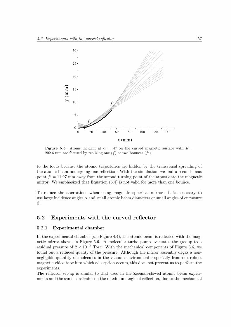
5.2 Experiments with the curved reflector 57
Figure 5.5: Atoms incident at α = 4 on the curved magnetic surface with R =202.6 mm are focused by realizing one (f) or two bounces (f ′).
to the focus because the atomic trajectories are hidden by the transversal spreading ofthe atomic beam undergoing one reflection. With the simulation, we find a second focuspoint f ′ = 11.97 mm away from the second turning point of the atoms onto the magneticmirror. We emphasized that Equation (5.4) is not valid for more than one bounce.
To reduce the aberrations when using magnetic spherical mirrors, it is necessary touse large incidence angles α and small atomic beam diameters or small angles of curvatureβ.
5.2 Experiments with the curved reflector
5.2.1 Experimental chamber
In the experimental chamber (see Figure 4.4), the atomic beam is reflected with the mag-netic mirror shown in Figure 5.6. A molecular turbo pump evacuates the gas up to aresidual pressure of 2 × 10⁻⁸ Torr. With the mechanical components of Figure 5.6, wefound out a reduced quality of the pressure. Although the mirror assembly degas a non-negligible quantity of molecules in the vacuum environment, especially from our robustmagnetic video tape into which adsorption occurs, this does not prevent us to perform theexperiments.The reflector set-up is similar to that used in the Zeeman-slowed atomic beam experi-ments and the same constraint on the maximum angle of reflection, due to the mechanical
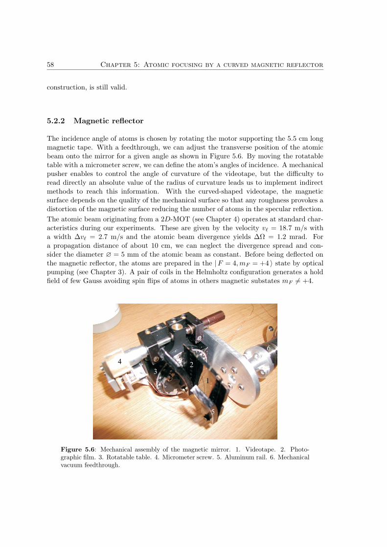
58 Chapter 5: Atomic focusing by a curved magnetic reflector
construction, is still valid.
5.2.2 Magnetic reflector
The incidence angle of atoms is chosen by rotating the motor supporting the 5.5 cm longmagnetic tape. With a feedthrough, we can adjust the transverse position of the atomicbeam onto the mirror for a given angle as shown in Figure 5.6. By moving the rotatabletable with a micrometer screw, we can define the atom’s angles of incidence. A mechanicalpusher enables to control the angle of curvature of the videotape, but the difficulty toread directly an absolute value of the radius of curvature leads us to implement indirectmethods to reach this information. With the curved-shaped videotape, the magneticsurface depends on the quality of the mechanical surface so that any roughness provokes adistortion of the magnetic surface reducing the number of atoms in the specular reflection.
The atomic beam originating from a 2D-MOT (see Chapter 4) operates at standard char-acteristics during our experiments. These are given by the velocity v` = 18.7 m/s witha width ∆v` = 2.7 m/s and the atomic beam divergence yields ∆Ω = 1.2 mrad. Fora propagation distance of about 10 cm, we can neglect the divergence spread and con-sider the diameter ∅ = 5 mm of the atomic beam as constant. Before being deflected onthe magnetic reflector, the atoms are prepared in the |F = 4, mF = +4 〉 state by opticalpumping (see Chapter 3). A pair of coils in the Helmholtz configuration generates a holdfield of few Gauss avoiding spin flips of atoms in others magnetic substates mF 6= +4.
Figure 5.6: Mechanical assembly of the magnetic mirror. 1. Videotape. 2. Photo-graphic film. 3. Rotatable table. 4. Micrometer screw. 5. Aluminum rail. 6. Mechanicalvacuum feedthrough.
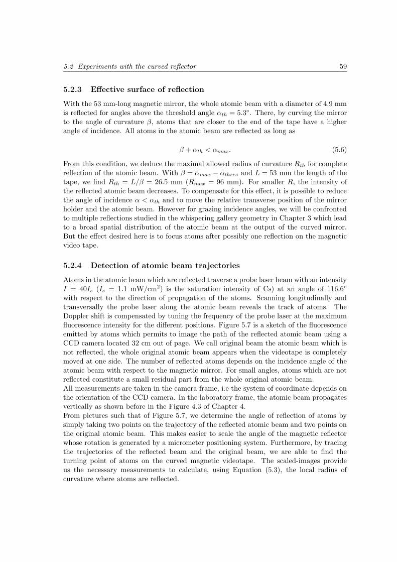
5.2 Experiments with the curved reflector 59
5.2.3 Effective surface of reflection
With the 53 mm-long magnetic mirror, the whole atomic beam with a diameter of 4.9 mmis reflected for angles above the threshold angle αth = 5.3. There, by curving the mirrorto the angle of curvature β, atoms that are closer to the end of the tape have a higherangle of incidence. All atoms in the atomic beam are reflected as long as
β + αth < αmax. (5.6)
From this condition, we deduce the maximal allowed radius of curvature Rth for completereflection of the atomic beam. With β = αmax − αthres and L = 53 mm the length of thetape, we find Rth = L/β = 26.5 mm (Rmax = 96 mm). For smaller R, the intensity ofthe reflected atomic beam decreases. To compensate for this effect, it is possible to reducethe angle of incidence α < αth and to move the relative transverse position of the mirrorholder and the atomic beam. However for grazing incidence angles, we will be confrontedto multiple reflections studied in the whispering gallery geometry in Chapter 3 which leadto a broad spatial distribution of the atomic beam at the output of the curved mirror.But the effect desired here is to focus atoms after possibly one reflection on the magneticvideo tape.
5.2.4 Detection of atomic beam trajectories
Atoms in the atomic beam which are reflected traverse a probe laser beam with an intensityI = 40Is (Is = 1.1 mW/cm2) is the saturation intensity of Cs) at an angle of 116.6
with respect to the direction of propagation of the atoms. Scanning longitudinally andtransversally the probe laser along the atomic beam reveals the track of atoms. TheDoppler shift is compensated by tuning the frequency of the probe laser at the maximumfluorescence intensity for the different positions. Figure 5.7 is a sketch of the fluorescenceemitted by atoms which permits to image the path of the reflected atomic beam using aCCD camera located 32 cm out of page. We call original beam the atomic beam which isnot reflected, the whole original atomic beam appears when the videotape is completelymoved at one side. The number of reflected atoms depends on the incidence angle of theatomic beam with respect to the magnetic mirror. For small angles, atoms which are notreflected constitute a small residual part from the whole original atomic beam.All measurements are taken in the camera frame, i.e the system of coordinate depends onthe orientation of the CCD camera. In the laboratory frame, the atomic beam propagatesvertically as shown before in the Figure 4.3 of Chapter 4.From pictures such that of Figure 5.7, we determine the angle of reflection of atoms bysimply taking two points on the trajectory of the reflected atomic beam and two points onthe original atomic beam. This makes easier to scale the angle of the magnetic reflectorwhose rotation is generated by a micrometer positioning system. Furthermore, by tracingthe trajectories of the reflected beam and the original beam, we are able to find theturning point of atoms on the curved magnetic videotape. The scaled-images provideus the necessary measurements to calculate, using Equation (5.3), the local radius ofcurvature where atoms are reflected.

60 Chapter 5: Atomic focusing by a curved magnetic reflector
Original atomic beam(without videotape)
Original atomic beam(with videotape)
Videotape
Laser beam
Camera frame
Reflected atomic beam
AOMOC
M
M
M
OF
y
x
Figure 5.7: Principle of detection. We have represented the photon emission from thereflected and original atomic beams induced by the probe laser beam for two differentpositions of the mirror (M).
In the following, the propagation of the atomic beam corresponds to that of the Figure5.7 which is the standard setup used for all experiments we carried out.
5.3 Results and discussions
5.3.1 Enhancement of the atomic beam density
The first attempt to concentrate the trajectories of atoms towards a common point wasrealized without mechanical pusher. Figure 5.8 a) is a composite of two CCD imagesshowing the reflected and the original atomic beams. The coordinate system used in theexperiments is shown in the picture. Atoms are incident at an angle of (3.9 ± 0.3) andthe number of reflected atoms is small compared to the original atomic beam. First, thisis due to the small angle of reflection i.e a small effective surface of the videotape ontowhich atoms reflect. Second, optical test of the mirror reduces the surface of reflectionto 21 mm as shown in Section 5.2.2, i.e all atoms in the atomic beam are reflected for
5.3 Results and discussions 61
Figure 5.8: Enhancement of the atomic density in the atomic beam. a) Added imagesof the reflected atomic beam and original atomic beam. The label (R) is made for thereflected beam whereas (O) is for the original beam. b) Cross section along the y-axisshowing the fluorescence intensity enhancement of the reflected atomic beam. The atomsare defected at αdefl = 7.8.
angles larger than αthres = 13.5. This condition is never fulfilled because atoms incidentat angles larger than αmax = 7.6 collide onto the videotape and are lost. Fortunatelywith only a small fraction of atoms, a compression of the initial atomic beam trajectoriesis realized along the propagation direction of atoms. This is illustrated in Figure 5.8 b),which shows the intensity of atoms versus their spatial position. The profiles correspondto the horizontal direction in Figure 5.8 a). The intensity is normalized to the maximumintensity of the reflected atoms. We recognize a small bump at small distances in thespatial distribution of the reflected atoms. This corresponds to a residual signal fromthe original atomic beam, i.e atoms that are not reflected by the videotape. The samephenomenon occurs in the distribution of atoms in the original atomic beam but dueto a different reason. The reflector moved completely at one side let the atomic beampropagating freely. However, the mirror is not far enough so that a small amount of atomslocated at the extremity of the atomic beam is still reflected and this results in a smallenhancement of atoms at a distance of 5.3 mm. The distribution of the original atomicbeam presents a slight asymmetry along the y direction originating from the radiationpressure and the angle of incidence of the probe laser beam. We see that the intensity ofthe reflected atomic beam increases up to a factor 2.2 with respect to the original atomicbeam. This first result proves that the magnetic mirror has a natural radius of curvatureand produces the expected effect. The reflector acts as a condensor lens.
We decided to reconstruct the path of atoms by moving the probe beam along the reflectedatomic beam axis. From our understanding, if a focus exists, we should be able to observe
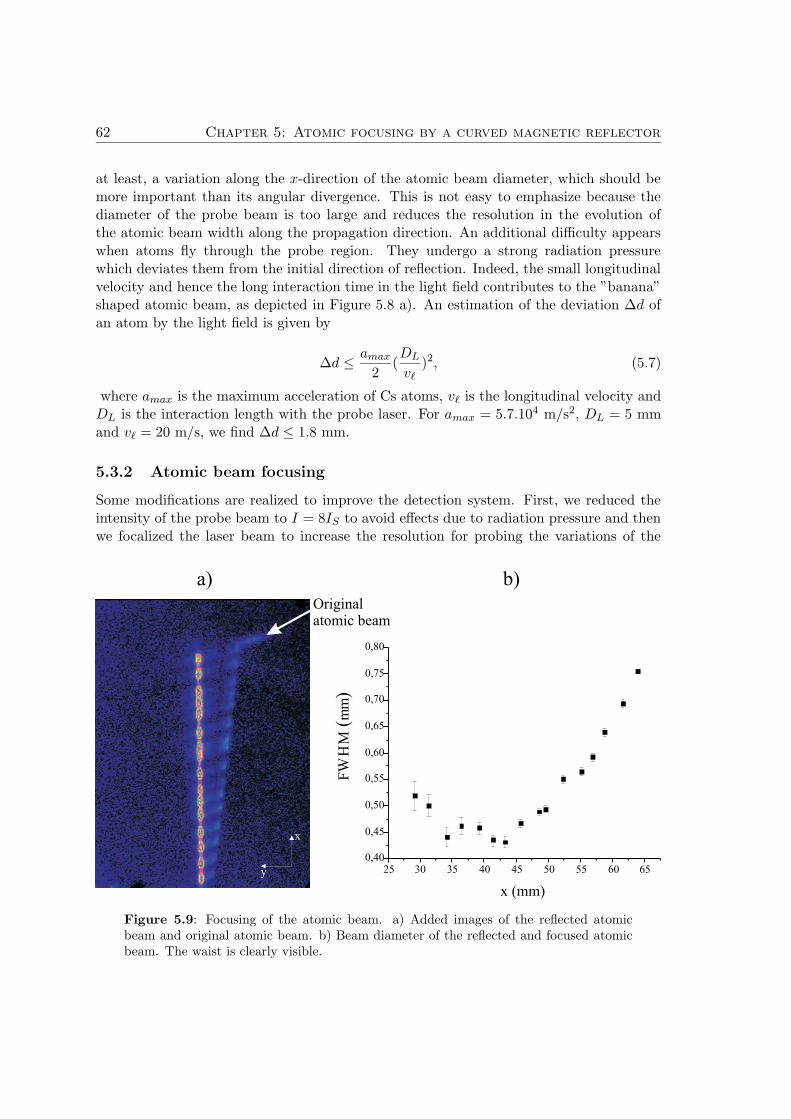
62 Chapter 5: Atomic focusing by a curved magnetic reflector
at least, a variation along the x-direction of the atomic beam diameter, which should bemore important than its angular divergence. This is not easy to emphasize because thediameter of the probe beam is too large and reduces the resolution in the evolution ofthe atomic beam width along the propagation direction. An additional difficulty appearswhen atoms fly through the probe region. They undergo a strong radiation pressurewhich deviates them from the initial direction of reflection. Indeed, the small longitudinalvelocity and hence the long interaction time in the light field contributes to the ”banana”shaped atomic beam, as depicted in Figure 5.8 a). An estimation of the deviation ∆d ofan atom by the light field is given by
∆d ≤ amax
2(DL
v`)2, (5.7)
where amax is the maximum acceleration of Cs atoms, v` is the longitudinal velocity andDL is the interaction length with the probe laser. For amax = 5.7.104 m/s2, DL = 5 mmand v` = 20 m/s, we find ∆d ≤ 1.8 mm.
5.3.2 Atomic beam focusing
Some modifications are realized to improve the detection system. First, we reduced theintensity of the probe beam to I = 8IS to avoid effects due to radiation pressure and thenwe focalized the laser beam to increase the resolution for probing the variations of the
Originalatomic beam
y
x
a) b)
25 30 35 40 45 50 55 60 650,40
0,45
0,50
0,55
0,60
0,65
0,70
0,75
0,80
FW
HM
(mm
)
x (mm)
Figure 5.9: Focusing of the atomic beam. a) Added images of the reflected atomicbeam and original atomic beam. b) Beam diameter of the reflected and focused atomicbeam. The waist is clearly visible.
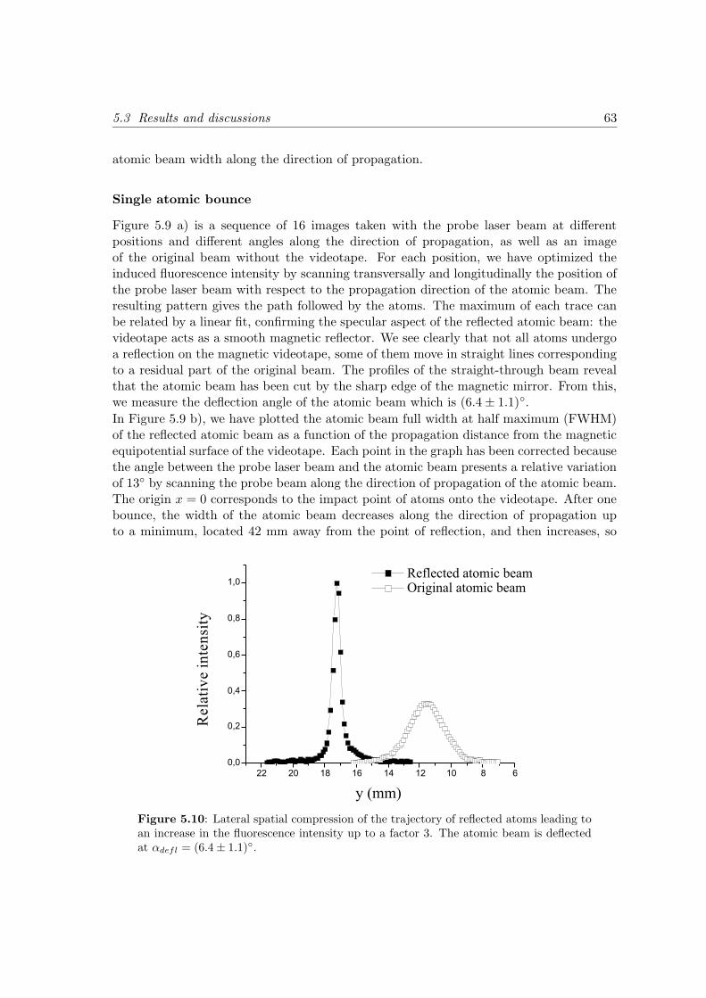
5.3 Results and discussions 63
atomic beam width along the direction of propagation.
Single atomic bounce
Figure 5.9 a) is a sequence of 16 images taken with the probe laser beam at differentpositions and different angles along the direction of propagation, as well as an imageof the original beam without the videotape. For each position, we have optimized theinduced fluorescence intensity by scanning transversally and longitudinally the position ofthe probe laser beam with respect to the propagation direction of the atomic beam. Theresulting pattern gives the path followed by the atoms. The maximum of each trace canbe related by a linear fit, confirming the specular aspect of the reflected atomic beam: thevideotape acts as a smooth magnetic reflector. We see clearly that not all atoms undergoa reflection on the magnetic videotape, some of them move in straight lines correspondingto a residual part of the original beam. The profiles of the straight-through beam revealthat the atomic beam has been cut by the sharp edge of the magnetic mirror. From this,we measure the deflection angle of the atomic beam which is (6.4 ± 1.1).
In Figure 5.9 b), we have plotted the atomic beam full width at half maximum (FWHM)of the reflected atomic beam as a function of the propagation distance from the magneticequipotential surface of the videotape. Each point in the graph has been corrected becausethe angle between the probe laser beam and the atomic beam presents a relative variationof 13 by scanning the probe beam along the direction of propagation of the atomic beam.The origin x = 0 corresponds to the impact point of atoms onto the videotape. After onebounce, the width of the atomic beam decreases along the direction of propagation upto a minimum, located 42 mm away from the point of reflection, and then increases, so
Figure 5.10: Lateral spatial compression of the trajectory of reflected atoms leading toan increase in the fluorescence intensity up to a factor 3. The atomic beam is deflectedat αdefl = (6.4 ± 1.1).
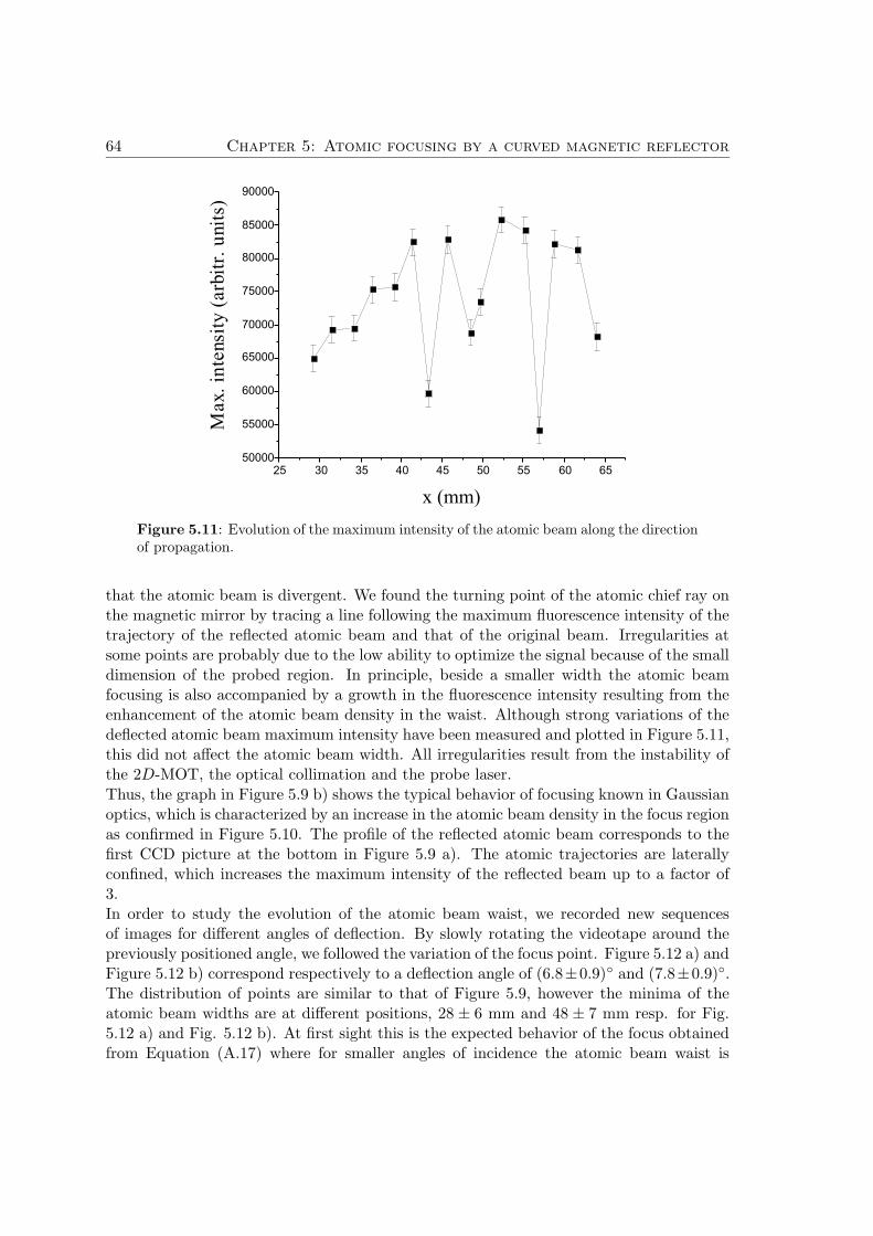
64 Chapter 5: Atomic focusing by a curved magnetic reflector
Figure 5.11: Evolution of the maximum intensity of the atomic beam along the directionof propagation.
that the atomic beam is divergent. We found the turning point of the atomic chief ray onthe magnetic mirror by tracing a line following the maximum fluorescence intensity of thetrajectory of the reflected atomic beam and that of the original beam. Irregularities atsome points are probably due to the low ability to optimize the signal because of the smalldimension of the probed region. In principle, beside a smaller width the atomic beamfocusing is also accompanied by a growth in the fluorescence intensity resulting from theenhancement of the atomic beam density in the waist. Although strong variations of thedeflected atomic beam maximum intensity have been measured and plotted in Figure 5.11,this did not affect the atomic beam width. All irregularities result from the instability ofthe 2D-MOT, the optical collimation and the probe laser.Thus, the graph in Figure 5.9 b) shows the typical behavior of focusing known in Gaussianoptics, which is characterized by an increase in the atomic beam density in the focus regionas confirmed in Figure 5.10. The profile of the reflected atomic beam corresponds to thefirst CCD picture at the bottom in Figure 5.9 a). The atomic trajectories are laterallyconfined, which increases the maximum intensity of the reflected beam up to a factor of3.In order to study the evolution of the atomic beam waist, we recorded new sequencesof images for different angles of deflection. By slowly rotating the videotape around thepreviously positioned angle, we followed the variation of the focus point. Figure 5.12 a) andFigure 5.12 b) correspond respectively to a deflection angle of (6.8±0.9) and (7.8±0.9).The distribution of points are similar to that of Figure 5.9, however the minima of theatomic beam widths are at different positions, 28 ± 6 mm and 48 ± 7 mm resp. for Fig.5.12 a) and Fig. 5.12 b). At first sight this is the expected behavior of the focus obtainedfrom Equation (A.17) where for smaller angles of incidence the atomic beam waist is
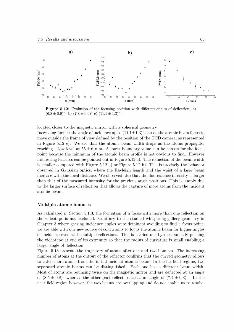
5.3 Results and discussions 65
Figure 5.12: Evolution of the focusing position with different angles of deflection: a)(6.8 ± 0.9). b) (7.8 ± 0.9) c) (11.1 ± 1.3).
located closer to the magnetic mirror with a spherical geometry.
Increasing further the angle of incidence up to (11.1±1.3) causes the atomic beam focus tomove outside the frame of view defined by the position of the CCD camera, as representedin Figure 5.12 c). We see that the atomic beam width drops as the atoms propagate,reaching a low level at 55 ± 6 mm. A lower boundary value can be chosen for the focuspoint because the minimum of the atomic beam profile is not obvious to find. Howeverinteresting features can be pointed out in Figure 5.12 c). The reduction of the beam widthis smaller compared with Figure 5.12 a) or Figure 5.12 b). This is precisely the behaviorobserved in Gaussian optics, where the Rayleigh length and the waist of a laser beamincrease with the focal distance. We observed also that the fluorescence intensity is largerthan that of the measured intensity for the previous angle positions. This is simply dueto the larger surface of reflection that allows the capture of more atoms from the incidentatomic beam.
Multiple atomic bounces
As calculated in Section 5.1.3, the formation of a focus with more than one reflection onthe videotape is not excluded. Contrary to the studied whispering-gallery geometry inChapter 3 where grazing incidence angles were dominant avoiding to find a focus point,we are able with our new source of cold atoms to focus the atomic beam for higher anglesof incidence even with multiple reflections. This is carried out by mechanically pushingthe videotape at one of its extremity so that the radius of curvature is small enabling alarger angle of deflection.
Figure 5.13 presents the trajectory of atoms after one and two bounces. The increasingnumber of atoms at the output of the reflector confirms that the curved geometry allowsto catch more atoms from the initial incident atomic beam. In the far field regime, twoseparated atomic beams can be distinguished. Each one has a different beam width.Most of atoms are bouncing twice on the magnetic mirror and are deflected at an angleof (8.5 ± 0.8) whereas the other part reflects once at an angle of (7.4 ± 0.8). In thenear field region however, the two beams are overlapping and do not enable us to resolve
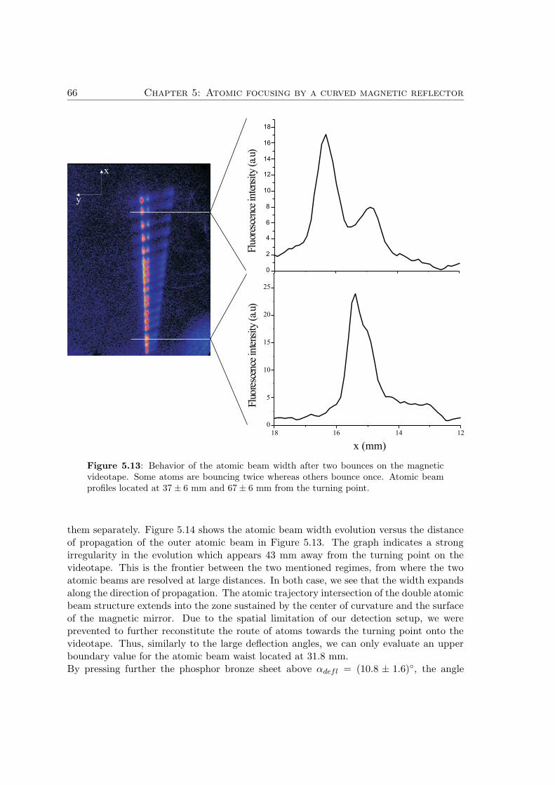
66 Chapter 5: Atomic focusing by a curved magnetic reflector
Figure 5.13: Behavior of the atomic beam width after two bounces on the magneticvideotape. Some atoms are bouncing twice whereas others bounce once. Atomic beamprofiles located at 37 ± 6 mm and 67 ± 6 mm from the turning point.
them separately. Figure 5.14 shows the atomic beam width evolution versus the distanceof propagation of the outer atomic beam in Figure 5.13. The graph indicates a strongirregularity in the evolution which appears 43 mm away from the turning point on thevideotape. This is the frontier between the two mentioned regimes, from where the twoatomic beams are resolved at large distances. In both case, we see that the width expandsalong the direction of propagation. The atomic trajectory intersection of the double atomicbeam structure extends into the zone sustained by the center of curvature and the surfaceof the magnetic mirror. Due to the spatial limitation of our detection setup, we wereprevented to further reconstitute the route of atoms towards the turning point onto thevideotape. Thus, similarly to the large deflection angles, we can only evaluate an upperboundary value for the atomic beam waist located at 31.8 mm.By pressing further the phosphor bronze sheet above αdefl = (10.8 ± 1.6), the angle
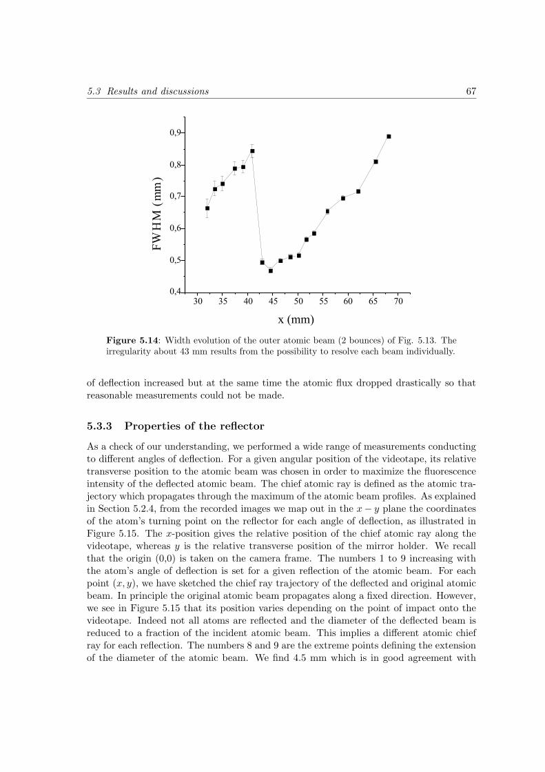
5.3 Results and discussions 67
Figure 5.14: Width evolution of the outer atomic beam (2 bounces) of Fig. 5.13. Theirregularity about 43 mm results from the possibility to resolve each beam individually.
of deflection increased but at the same time the atomic flux dropped drastically so thatreasonable measurements could not be made.
5.3.3 Properties of the reflector
As a check of our understanding, we performed a wide range of measurements conductingto different angles of deflection. For a given angular position of the videotape, its relativetransverse position to the atomic beam was chosen in order to maximize the fluorescenceintensity of the deflected atomic beam. The chief atomic ray is defined as the atomic tra-jectory which propagates through the maximum of the atomic beam profiles. As explainedin Section 5.2.4, from the recorded images we map out in the x− y plane the coordinatesof the atom’s turning point on the reflector for each angle of deflection, as illustrated inFigure 5.15. The x-position gives the relative position of the chief atomic ray along thevideotape, whereas y is the relative transverse position of the mirror holder. We recallthat the origin (0,0) is taken on the camera frame. The numbers 1 to 9 increasing withthe atom’s angle of deflection is set for a given reflection of the atomic beam. For eachpoint (x, y), we have sketched the chief ray trajectory of the deflected and original atomicbeam. In principle the original atomic beam propagates along a fixed direction. However,we see in Figure 5.15 that its position varies depending on the point of impact onto thevideotape. Indeed not all atoms are reflected and the diameter of the deflected beam isreduced to a fraction of the incident atomic beam. This implies a different atomic chiefray for each reflection. The numbers 8 and 9 are the extreme points defining the extensionof the diameter of the atomic beam. We find 4.5 mm which is in good agreement with
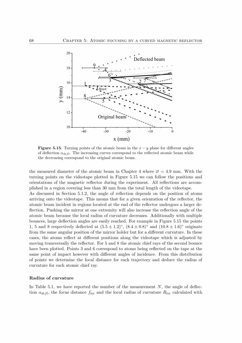
68 Chapter 5: Atomic focusing by a curved magnetic reflector
Figure 5.15: Turning points of the atomic beam in the x − y plane for different anglesof deflection αdefl. The increasing curves correspond to the reflected atomic beam whilethe decreasing correspond to the original atomic beam.
the measured diameter of the atomic beam in Chapter 4 where ∅ = 4.9 mm. With theturning points on the videotape plotted in Figure 5.15 we can follow the positions andorientations of the magnetic reflector during the experiment. All reflections are accom-plished in a region covering less than 30 mm from the total length of the videotape.As discussed in Section 5.1.2, the angle of reflection depends on the position of atomsarriving onto the videotape. This means that for a given orientation of the reflector, theatomic beam incident in regions located at the end of the reflector undergoes a larger de-flection. Pushing the mirror at one extremity will also increase the reflection angle of theatomic beam because the local radius of curvature decreases. Additionally with multiplebounces, large deflection angles are easily reached. For example in Figure 5.15 the points1, 5 and 8 respectively deflected at (5.5 ± 1.2), (8.4 ± 0.8) and (10.8 ± 1.6) originatefrom the same angular position of the mirror holder but for a different curvature. In thesecases, the atoms reflect at different positions along the videotape which is adjusted bymoving transversally the reflector. For 5 and 8 the atomic chief rays of the second bouncehave been plotted. Points 3 and 6 correspond to atoms being reflected on the tape at thesame point of impact however with different angles of incidence. From this distributionof points we determine the focal distance for each trajectory and deduce the radius ofcurvature for each atomic chief ray.
Radius of curvature
In Table 5.1, we have reported the number of the measurement N , the angle of deflec-tion αdefl, the focus distance floc and the local radius of curvature Rloc calculated with
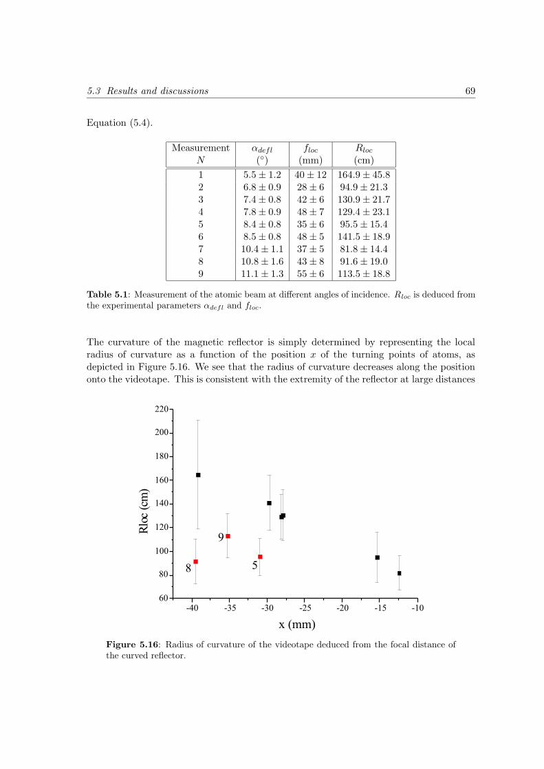
5.3 Results and discussions 69
Equation (5.4).
Measurement αdefl floc Rloc
N () (mm) (cm)
1 5.5 ± 1.2 40 ± 12 164.9 ± 45.82 6.8 ± 0.9 28 ± 6 94.9 ± 21.33 7.4 ± 0.8 42 ± 6 130.9 ± 21.74 7.8 ± 0.9 48 ± 7 129.4 ± 23.15 8.4 ± 0.8 35 ± 6 95.5 ± 15.46 8.5 ± 0.8 48 ± 5 141.5 ± 18.97 10.4 ± 1.1 37 ± 5 81.8 ± 14.48 10.8 ± 1.6 43 ± 8 91.6 ± 19.09 11.1 ± 1.3 55 ± 6 113.5 ± 18.8
Table 5.1: Measurement of the atomic beam at different angles of incidence. Rloc is deduced fromthe experimental parameters αdefl and floc.
The curvature of the magnetic reflector is simply determined by representing the localradius of curvature as a function of the position x of the turning points of atoms, asdepicted in Figure 5.16. We see that the radius of curvature decreases along the positiononto the videotape. This is consistent with the extremity of the reflector at large distances
Figure 5.16: Radius of curvature of the videotape deduced from the focal distance ofthe curved reflector.
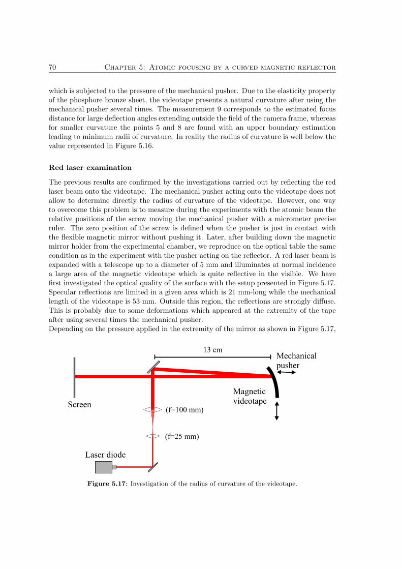
70 Chapter 5: Atomic focusing by a curved magnetic reflector
which is subjected to the pressure of the mechanical pusher. Due to the elasticity propertyof the phosphore bronze sheet, the videotape presents a natural curvature after using themechanical pusher several times. The measurement 9 corresponds to the estimated focusdistance for large deflection angles extending outside the field of the camera frame, whereasfor smaller curvature the points 5 and 8 are found with an upper boundary estimationleading to minimum radii of curvature. In reality the radius of curvature is well below thevalue represented in Figure 5.16.
Red laser examination
The previous results are confirmed by the investigations carried out by reflecting the redlaser beam onto the videotape. The mechanical pusher acting onto the videotape does notallow to determine directly the radius of curvature of the videotape. However, one wayto overcome this problem is to measure during the experiments with the atomic beam therelative positions of the screw moving the mechanical pusher with a micrometer preciseruler. The zero position of the screw is defined when the pusher is just in contact withthe flexible magnetic mirror without pushing it. Later, after building down the magneticmirror holder from the experimental chamber, we reproduce on the optical table the samecondition as in the experiment with the pusher acting on the reflector. A red laser beam isexpanded with a telescope up to a diameter of 5 mm and illuminates at normal incidencea large area of the magnetic videotape which is quite reflective in the visible. We havefirst investigated the optical quality of the surface with the setup presented in Figure 5.17.Specular reflections are limited in a given area which is 21 mm-long while the mechanicallength of the videotape is 53 mm. Outside this region, the reflections are strongly diffuse.This is probably due to some deformations which appeared at the extremity of the tapeafter using several times the mechanical pusher.Depending on the pressure applied in the extremity of the mirror as shown in Figure 5.17,
(f=25 mm)
(f=100 mm)
13 cm
Screen
Magneticvideotape
Mechanicalpusher
Laser diode
Figure 5.17: Investigation of the radius of curvature of the videotape.
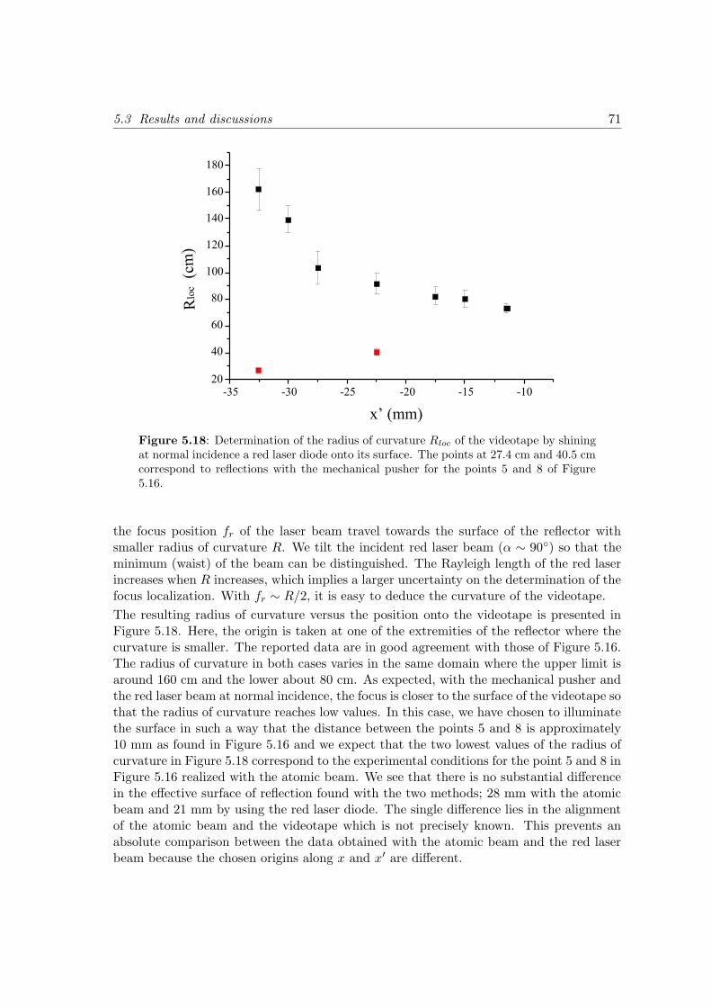
5.3 Results and discussions 71
Figure 5.18: Determination of the radius of curvature Rloc of the videotape by shiningat normal incidence a red laser diode onto its surface. The points at 27.4 cm and 40.5 cmcorrespond to reflections with the mechanical pusher for the points 5 and 8 of Figure5.16.
the focus position fr of the laser beam travel towards the surface of the reflector withsmaller radius of curvature R. We tilt the incident red laser beam (α ∼ 90) so that theminimum (waist) of the beam can be distinguished. The Rayleigh length of the red laserincreases when R increases, which implies a larger uncertainty on the determination of thefocus localization. With fr ∼ R/2, it is easy to deduce the curvature of the videotape.
The resulting radius of curvature versus the position onto the videotape is presented inFigure 5.18. Here, the origin is taken at one of the extremities of the reflector where thecurvature is smaller. The reported data are in good agreement with those of Figure 5.16.The radius of curvature in both cases varies in the same domain where the upper limit isaround 160 cm and the lower about 80 cm. As expected, with the mechanical pusher andthe red laser beam at normal incidence, the focus is closer to the surface of the videotape sothat the radius of curvature reaches low values. In this case, we have chosen to illuminatethe surface in such a way that the distance between the points 5 and 8 is approximately10 mm as found in Figure 5.16 and we expect that the two lowest values of the radius ofcurvature in Figure 5.18 correspond to the experimental conditions for the point 5 and 8 inFigure 5.16 realized with the atomic beam. We see that there is no substantial differencein the effective surface of reflection found with the two methods; 28 mm with the atomicbeam and 21 mm by using the red laser diode. The single difference lies in the alignmentof the atomic beam and the videotape which is not precisely known. This prevents anabsolute comparison between the data obtained with the atomic beam and the red laserbeam because the chosen origins along x and x′ are different.
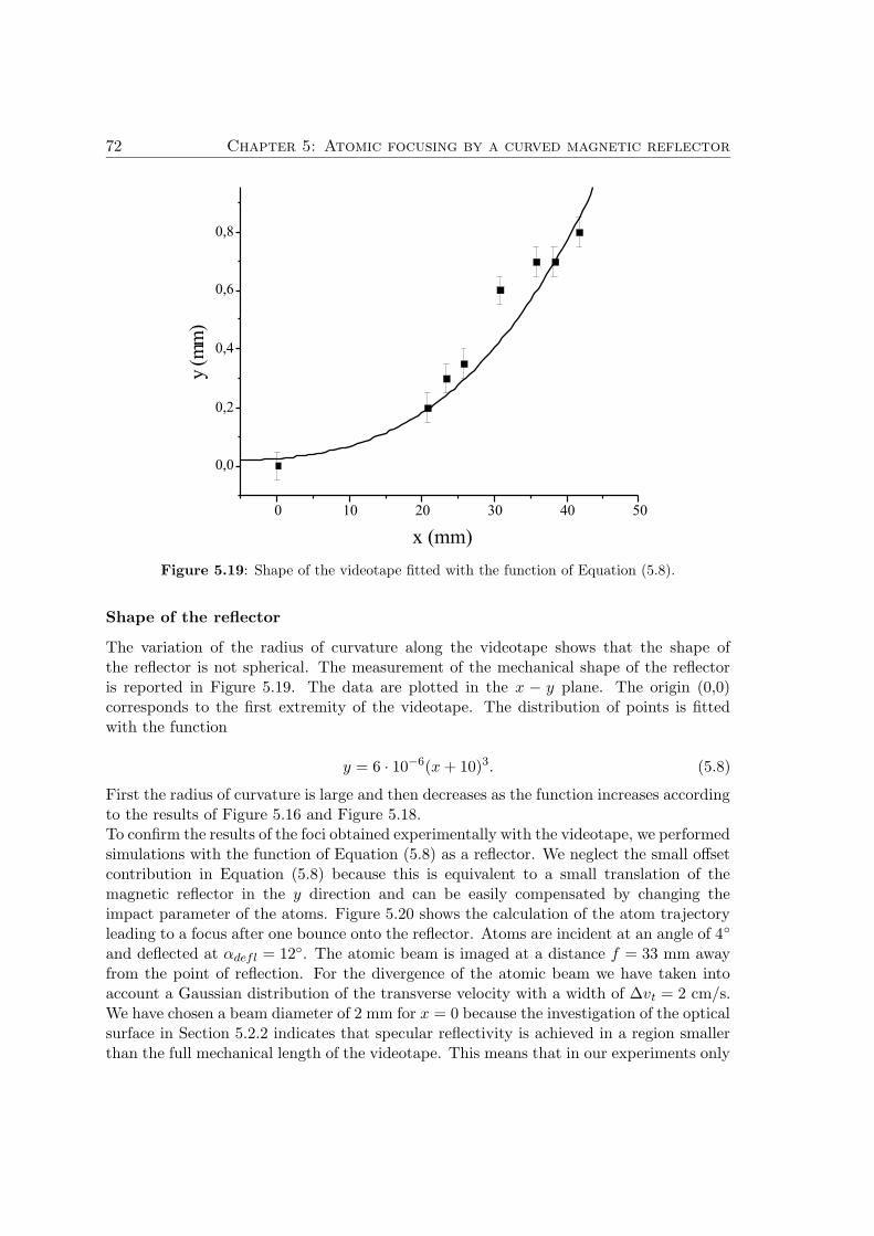
72 Chapter 5: Atomic focusing by a curved magnetic reflector
Figure 5.19: Shape of the videotape fitted with the function of Equation (5.8).
Shape of the reflector
The variation of the radius of curvature along the videotape shows that the shape ofthe reflector is not spherical. The measurement of the mechanical shape of the reflectoris reported in Figure 5.19. The data are plotted in the x − y plane. The origin (0,0)corresponds to the first extremity of the videotape. The distribution of points is fittedwith the function
y = 6 · 10−6(x + 10)3. (5.8)
First the radius of curvature is large and then decreases as the function increases accordingto the results of Figure 5.16 and Figure 5.18.To confirm the results of the foci obtained experimentally with the videotape, we performedsimulations with the function of Equation (5.8) as a reflector. We neglect the small offsetcontribution in Equation (5.8) because this is equivalent to a small translation of themagnetic reflector in the y direction and can be easily compensated by changing theimpact parameter of the atoms. Figure 5.20 shows the calculation of the atom trajectoryleading to a focus after one bounce onto the reflector. Atoms are incident at an angle of 4
and deflected at αdefl = 12. The atomic beam is imaged at a distance f = 33 mm awayfrom the point of reflection. For the divergence of the atomic beam we have taken intoaccount a Gaussian distribution of the transverse velocity with a width of ∆vt = 2 cm/s.We have chosen a beam diameter of 2 mm for x = 0 because the investigation of the opticalsurface in Section 5.2.2 indicates that specular reflectivity is achieved in a region smallerthan the full mechanical length of the videotape. This means that in our experiments only
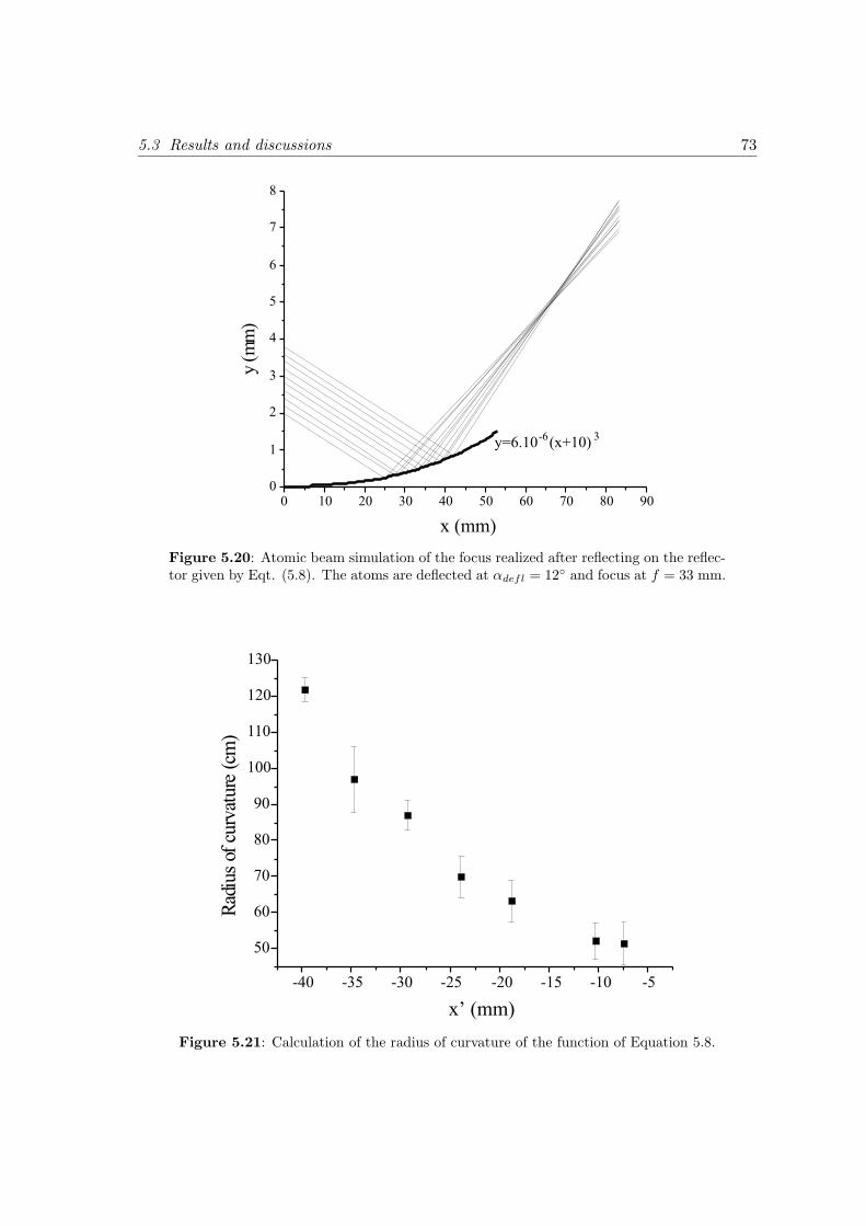
5.3 Results and discussions 73
Figure 5.20: Atomic beam simulation of the focus realized after reflecting on the reflec-tor given by Eqt. (5.8). The atoms are deflected at αdefl = 12 and focus at f = 33 mm.
Figure 5.21: Calculation of the radius of curvature of the function of Equation 5.8.
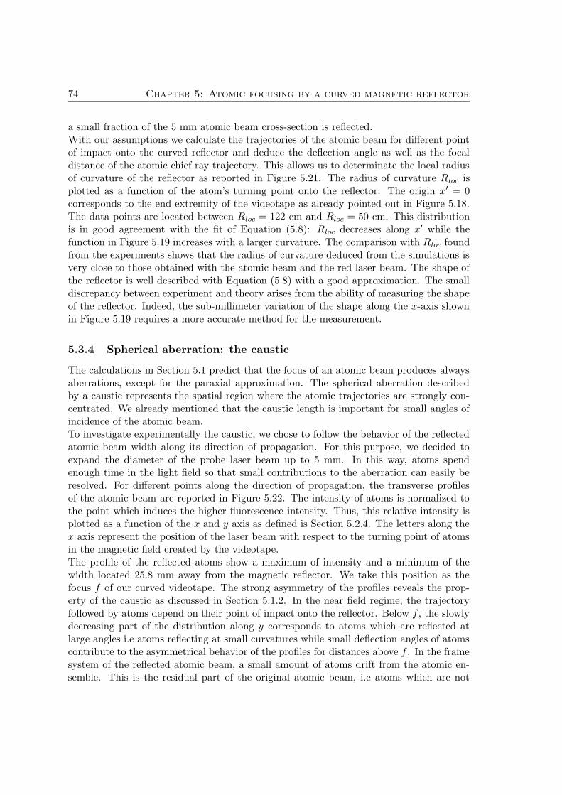
74 Chapter 5: Atomic focusing by a curved magnetic reflector
a small fraction of the 5 mm atomic beam cross-section is reflected.With our assumptions we calculate the trajectories of the atomic beam for different pointof impact onto the curved reflector and deduce the deflection angle as well as the focaldistance of the atomic chief ray trajectory. This allows us to determinate the local radiusof curvature of the reflector as reported in Figure 5.21. The radius of curvature Rloc isplotted as a function of the atom’s turning point onto the reflector. The origin x′ = 0corresponds to the end extremity of the videotape as already pointed out in Figure 5.18.The data points are located between Rloc = 122 cm and Rloc = 50 cm. This distributionis in good agreement with the fit of Equation (5.8): Rloc decreases along x′ while thefunction in Figure 5.19 increases with a larger curvature. The comparison with Rloc foundfrom the experiments shows that the radius of curvature deduced from the simulations isvery close to those obtained with the atomic beam and the red laser beam. The shape ofthe reflector is well described with Equation (5.8) with a good approximation. The smalldiscrepancy between experiment and theory arises from the ability of measuring the shapeof the reflector. Indeed, the sub-millimeter variation of the shape along the x-axis shownin Figure 5.19 requires a more accurate method for the measurement.
5.3.4 Spherical aberration: the caustic
The calculations in Section 5.1 predict that the focus of an atomic beam produces alwaysaberrations, except for the paraxial approximation. The spherical aberration describedby a caustic represents the spatial region where the atomic trajectories are strongly con-centrated. We already mentioned that the caustic length is important for small angles ofincidence of the atomic beam.To investigate experimentally the caustic, we chose to follow the behavior of the reflectedatomic beam width along its direction of propagation. For this purpose, we decided toexpand the diameter of the probe laser beam up to 5 mm. In this way, atoms spendenough time in the light field so that small contributions to the aberration can easily beresolved. For different points along the direction of propagation, the transverse profilesof the atomic beam are reported in Figure 5.22. The intensity of atoms is normalized tothe point which induces the higher fluorescence intensity. Thus, this relative intensity isplotted as a function of the x and y axis as defined is Section 5.2.4. The letters along thex axis represent the position of the laser beam with respect to the turning point of atomsin the magnetic field created by the videotape.The profile of the reflected atoms show a maximum of intensity and a minimum of thewidth located 25.8 mm away from the magnetic reflector. We take this position as thefocus f of our curved videotape. The strong asymmetry of the profiles reveals the prop-erty of the caustic as discussed in Section 5.1.2. In the near field regime, the trajectoryfollowed by atoms depend on their point of impact onto the reflector. Below f , the slowlydecreasing part of the distribution along y corresponds to atoms which are reflected atlarge angles i.e atoms reflecting at small curvatures while small deflection angles of atomscontribute to the asymmetrical behavior of the profiles for distances above f . In the framesystem of the reflected atomic beam, a small amount of atoms drift from the atomic en-semble. This is the residual part of the original atomic beam, i.e atoms which are not
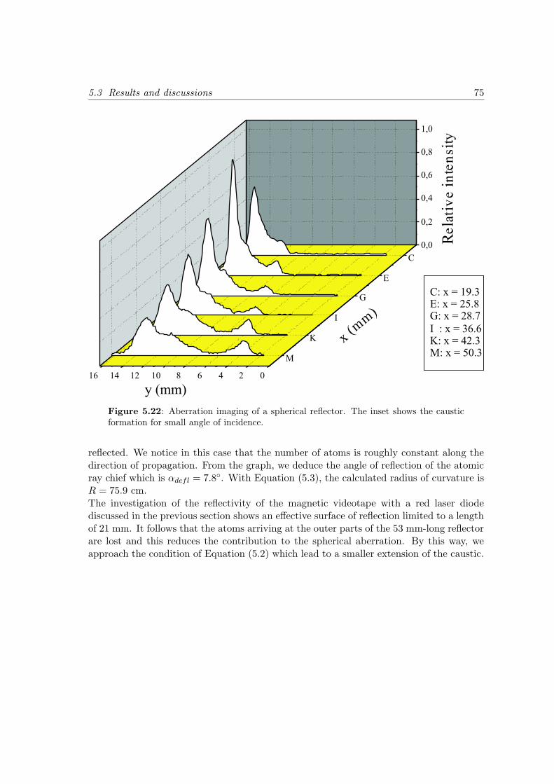
5.3 Results and discussions 75
Figure 5.22: Aberration imaging of a spherical reflector. The inset shows the causticformation for small angle of incidence.
reflected. We notice in this case that the number of atoms is roughly constant along thedirection of propagation. From the graph, we deduce the angle of reflection of the atomicray chief which is αdefl = 7.8. With Equation (5.3), the calculated radius of curvature isR = 75.9 cm.The investigation of the reflectivity of the magnetic videotape with a red laser diodediscussed in the previous section shows an effective surface of reflection limited to a lengthof 21 mm. It follows that the atoms arriving at the outer parts of the 53 mm-long reflectorare lost and this reduces the contribution to the spherical aberration. By this way, weapproach the condition of Equation (5.2) which lead to a smaller extension of the caustic.

Chapter 6
Conclusion and outlook
We have shown through this thesis that videotapes can be used as a high-quality atomicbeam reflector for reflective atom optics. We have developed a new technique formounting the videotape so that the shape can be reliably made flexible and the reflectingsurface can conform closely to the desired geometry. In order to perform the experiments,we have prepared two types of atomic beams.With the first, the Zeeman-slowed atomic beam, atoms at grazing incidence and travelingat 60 m/s were reflected onto the videotape. We have used the atom beam itself tocalibrate the strength of the magnetic field at the surface of the tape. In analogy withthe x-ray optics in which optical components at grazing-incidence are well-known, wehave demonstrated that a curved videotape can deflect atoms at angles as large as 23
in a whispering-gallery configuration. We have shown that with an adequate angle ofincidence the number of reflections realized by the atomic beam can be counted.The second beam arises from a cold atomic source, the 2D-MOT. The atoms are extractedwith a pusher laser beam which is separated from the atomic beam by slowly tiltingthe optical collimating stage or the pusher beam itself. With this setup, we were ableto obtain a well-collimated and optically pumped slowed atomic beam propagating at20 m/s. This enables with one bounce to reflect atoms onto the videotape at angles ofincidence up to 7. Thus, we have demonstrated the focusing of the atomic beam with thenatural curvature of the videotape at different angles of deflection. We have shown thatfocusing is not limited to atoms which bounce once but can also be realized with multiplebounces. The focal length depends on the point of impact of atoms onto the curvedreflector. We have deduced the radii of curvature of the videotape from the angles ofdeflection and the corresponding focal lengths. The values found were in good agreementwith the measurements of the radii of curvature determined with a red laser beam atnormal incidence onto the reflector. We have confirmed the experimental results byfirst measuring approximatively the shape of the videotape and found that the function∼ x3 describes it well. We have performed simulations with the atomic beam incident atdifferent parameters of impact and have calculated the radii of curvature at these pointsalong the videotape. Finally, we have shown that spherical aberrations, i.e the caustic,concentrate the atomic trajectories along a well-defined curved. We have emphasized
77
78 Chapter 6: Conclusion and outlook
that a more localized focal point can be reached either with small angles of curvature βof the videotape or with large incidence angles α and small atomic beam diameters.Thus, the reduction of the caustic length requires eventually a compression of the atomicbeam by moving the optical collimation system closer to the mechanical hole in thealuminum mirror in the glass cell or with a compression stage which is composed ofmagnetic and light forces [84]. Larger angles of incidence can be enhanced by furtherreducing the longitudinal velocity of the atomic beam. This can be realized by adding alaser beam which counterpropagates the pusher beam with a different detuning. Also byincreasing the thickness of the videotape, we can improve the surface field strength andhence the maximal transverse velocity allowing the reflection of atoms by the magneticmirror.
These results pave the way for new experiments with the videotape as a tool foratom optics. Although magnetic mirrors based on permanent magnetization are passiveand do not allow temporal variations of the magnetic potential, it has been shown ina recent PhD-thesis [74] that the reflective magnetic surface of the videotape can beadapted by the addition of a suitable external field. For example, the principle of theatomic grating [85, 86] can be applied for the diffraction of atomic beams. We expect inthat way to produce monochromatic atomic beams.The videotape can also be used as a deflector for atoms between two experimental cham-bers and do not require heavy materials for guiding atoms as in [87]. The extension ofthe whispering-gallery geometry to a storage ring for neutral atoms opens new prospectsin ring-based atomic interferometry [88, 89]. This configuration provides also newpossibilities to create ultra-cold atomic beams. For example, atoms can be continuouslyloaded in the ring, and both the longitudinal and transversal velocity distributions ofatoms can be cooled in the ring.A straightforward application of the atomic beam imaging shown in this work is theatomic lithography. Generating structures in the sub-micrometer domain has increasedthe interest in exploring various methods for the production of any patterns [34]. Inour lab, it has been shown recently that a thermal atomic beam focused by means of arefractive magnetic lens enables to write micrometer-sized samples. With a cantilever usedas a shadow mask, sub-micrometer dimensions are expected to be reached. By replacingthe refractive lens with a reflective element like the videotape, we take advantage of thepossibility to eliminate the chromatic aberrations. Even if other aberrations appear, wecan easily correct them due to the high flexibility of the videotape allowing to shape thereflector in any geometry [19]. With these assumptions reflective atomic nanofabricationcould be a serious candidate to compete with refractive atomic lithography.
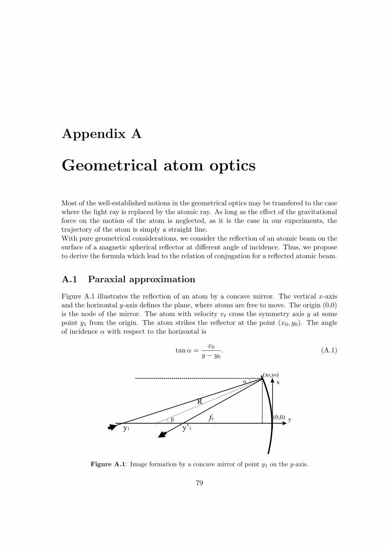
Appendix A
Geometrical atom optics
Most of the well-established notions in the geometrical optics may be transfered to the casewhere the light ray is replaced by the atomic ray. As long as the effect of the gravitationalforce on the motion of the atom is neglected, as it is the case in our experiments, thetrajectory of the atom is simply a straight line.
With pure geometrical considerations, we consider the reflection of an atomic beam on thesurface of a magnetic spherical reflector at different angle of incidence. Thus, we proposeto derive the formula which lead to the relation of conjugation for a reflected atomic beam.
A.1 Paraxial approximation
Figure A.1 illustrates the reflection of an atom by a concave mirror. The vertical x-axisand the horizontal y-axis defines the plane, where atoms are free to move. The origin (0,0)is the node of the mirror. The atom with velocity v` cross the symmetry axis y at somepoint y1 from the origin. The atom strikes the reflector at the point (x0, y0). The angleof incidence α with respect to the horizontal is
tan α =x0
y − y0. (A.1)
R
y’1y1
f0 y
x
(0,0)
(x ,y )0 0
b
a
Figure A.1: Image formation by a concave mirror of point y1 on the y-axis.
79
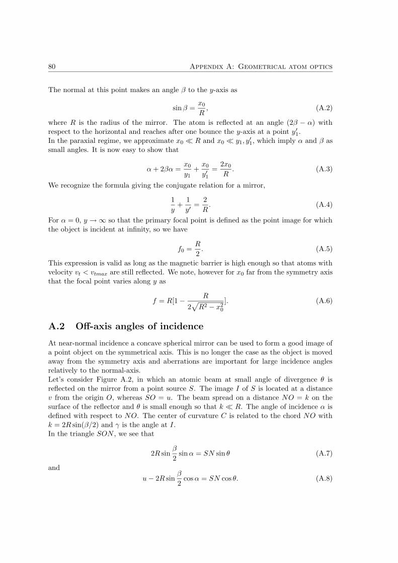
80 Appendix A: Geometrical atom optics
The normal at this point makes an angle β to the y-axis as
sin β =x0
R, (A.2)
where R is the radius of the mirror. The atom is reflected at an angle (2β − α) withrespect to the horizontal and reaches after one bounce the y-axis at a point y ′
1.In the paraxial regime, we approximate x0 R and x0 y1, y
′1, which imply α and β as
small angles. It is now easy to show that
α + 2βα =x0
y1+
x0
y′1=
2x0
R. (A.3)
We recognize the formula giving the conjugate relation for a mirror,
1
y+
1
y′=
2
R. (A.4)
For α = 0, y → ∞ so that the primary focal point is defined as the point image for whichthe object is incident at infinity, so we have
f0 =R
2. (A.5)
This expression is valid as long as the magnetic barrier is high enough so that atoms withvelocity vt < vtmax are still reflected. We note, however for x0 far from the symmetry axisthat the focal point varies along y as
f = R[1 − R
2√
R2 − x20
]. (A.6)
A.2 Off-axis angles of incidence
At near-normal incidence a concave spherical mirror can be used to form a good image ofa point object on the symmetrical axis. This is no longer the case as the object is movedaway from the symmetry axis and aberrations are important for large incidence anglesrelatively to the normal-axis.Let’s consider Figure A.2, in which an atomic beam at small angle of divergence θ isreflected on the mirror from a point source S. The image I of S is located at a distancev from the origin O, whereas SO = u. The beam spread on a distance NO = k on thesurface of the reflector and θ is small enough so that k R. The angle of incidence α isdefined with respect to NO. The center of curvature C is related to the chord NO withk = 2R sin(β/2) and γ is the angle at I.In the triangle SON , we see that
2R sinβ
2sin α = SN sin θ (A.7)
and
u − 2R sinβ
2cos α = SN cos θ. (A.8)
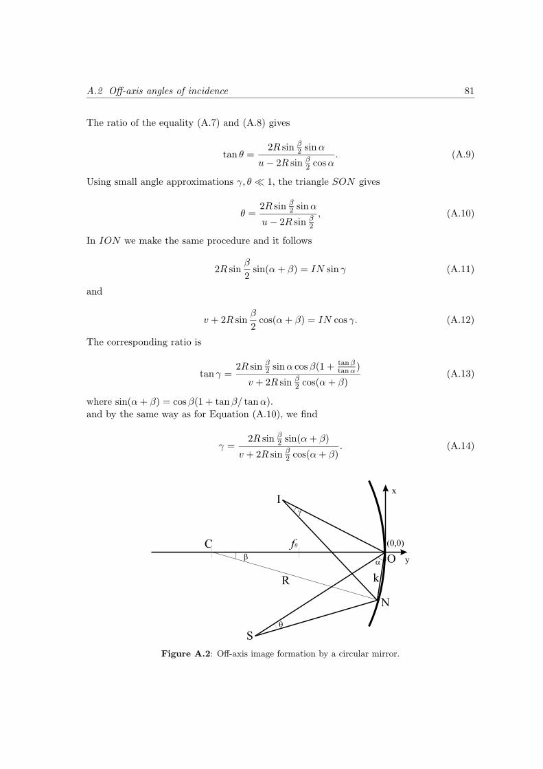
A.2 Off-axis angles of incidence 81
The ratio of the equality (A.7) and (A.8) gives
tan θ =2R sin β
2 sin α
u − 2R sin β2 cos α
. (A.9)
Using small angle approximations γ, θ 1, the triangle SON gives
θ =2R sin β
2 sin α
u − 2R sin β2
, (A.10)
In ION we make the same procedure and it follows
2R sinβ
2sin(α + β) = IN sin γ (A.11)
and
v + 2R sinβ
2cos(α + β) = IN cos γ. (A.12)
The corresponding ratio is
tan γ =2R sin β
2 sin α cos β(1 + tan βtan α)
v + 2R sin β2 cos(α + β)
(A.13)
where sin(α + β) = cos β(1 + tan β/ tan α).
and by the same way as for Equation (A.10), we find
γ =2R sin β
2 sin(α + β)
v + 2R sin β2 cos(α + β)
. (A.14)
O
N
k
I
S
C
R
f0
x
y
(0,0)
b
q
g
a
Figure A.2: Off-axis image formation by a circular mirror.
82 Appendix A: Geometrical atom optics
From the law of reflection, where γ + θ = 2β [90], we obtain with equations (A.10) and(A.14)
1
u − 2R sin β2 cos α
+cos β(1 + tan β
tan α)
v + 2R sin β2 cos(α + β)
=2β
2R sin β2 sin α
, (A.15)
which for small β reduces to the image-mirror equation
1
u+
1
v=
2
R sin α. (A.16)
With u → ∞, the focal point f is
f = fm =R
2sin α. (A.17)
For α = π/2, we find the particular condition of equation (A.5). For a wide variety ofangles α, the image points form a parabola. In the three dimensional case, fm is known asthe meridian focal length and the phenomenon of astigmatism occurs. Instead of a pointimage, two mutually perpendicular line images are formed. Thus, the second focal lengthis the sagittal focal length fs .
Bibliography
[1] W. Gerlach and O. Stern, Der experimentelle Nachweis des magnetischen Moments des
Silberatoms, Z. Phys. (8), 110–111 (1921)
[2] O. Frisch, Experimenteller Nachweis des Einsteinschen Strahlungsrckstoßes, Z. Physik (86),42 (1933)
[3] H. Friedburg and W. Paul, Optische Abbildung mit neutralen Atomen, Naturwis-senschaften (38), 159–160 (1951)
[4] H. Metcalf and P. van der Straten, Laser Cooling and Trapping , Springer (1999)
[5] F. Shimizu, Specular reflection of very slow metastable neon atoms from a solid surface, Phys.Rev. Lett. 86(5), 987–990 (2001)
[6] O. Carnal, M. Sigel, T. Sleator, H. Takuma and J. Mlynek, Imaging and focusing
of atoms by a fresnel zone plate, Phys. Rev. Lett. 67(23), 3231–3234 (1991)
[7] M. Boustimi, J. B. M. Ducloy, J. Reinhardt, F. Perales, C. Mainos, V. Bocvarskiand J. Robert, Mestastable rare gas atoms scattered by nano- and micro-slit transmission
gratings, Eur. Phys. J. D (17), 141–144 (2001)
[8] V. Balykin, V. Letokhov, Y. Ovchinnikov and A. Sidorov, Quantum state selective
mirror reflection of atoms by laser light , Phys. Rev. Lett. 60(21), 2137–2140 (1988)
[9] J. Bjorkholm, R. Freeman, A. Ashkin and D. Pearson, Observation of focusing of
neutral atoms by the dipole forces of resonance-radiation pressure, Phys. Rev. Lett. 41(20),1361–1364 (1978)
[10] J. Dowling and J. Gea-Banacloche, Evanescent light-wave atom mirrors, resonators,
waveguides, and traps, Adv.At.Mol.Opt.Phys. (37), 1–94 (1996)
[11] P. Desbiolles, M. Arndt, P. Szriftgiser and J. Dalibard, Dissipative atom optics,J. Mod. Opt. (44), 1827 (1997)
[12] W. Kaenders, F. Lison, A. Richter, R. Wynands and D. Meschede, Imaging with
an atomic-beam, Nature (375), 214–216 (1995)
[13] W. Kaenders, F. Lison, I. Muller, A. Richter, R. Wynands and D. Meschede,Refractive components for magnetic atom optics, Phys. Rev. A 54(6), 5067–75 (1996)
[14] T. Roach, H. Abele, M. Boshier, H. Grossman, K. Zetie and E. Hinds, Realization
of a Magnetic Mirror for Cold Atoms, Phys. Rev. Lett. 75(4), 629–632 (1995)
[15] I. Hughes, P. Barton, T. Roach and E. Hinds, Atom optics with magnetic surfaces: I.
Storage of cold atoms in curved ’floppy disk’ , J. Phys. B: At. Mol. Opt. Phys. (30), 647–658(1997)
83

84 BIBLIOGRAPHY
[16] I. Hughes, P. Barton, T. Roach and E. Hinds, Atom optics with magnetic surfaces: II.
Microscopic analysis of the ’floppy disk’ mirror , J. Phys. B: At. Mol. Phys. (30), 2119–2132(1997)
[17] C. Saba, P. Barton, M. Boshier, I. Hughes, P. Rosenbusch, B. Sauer and E. Hinds,Reconstruction of a Cold Atom Cloud by Magnetic Focusing , Phys. Rev. Lett 82(3), 468–471(1999)
[18] M. Born and E. Wolf, Principles of Optics, Oxford:Pergamon, 6th edition (1980)
[19] D. Korsch, Reflective optics, Academic Press (1991)
[20] P. Molenaar, P. V. der Straten, H. Heideman and H. Metcalf, Diagnostic technique
for Zeeman-compensated atomic beam slowing: Technique and results, Phys. Rev. A 55(1),605–14 (1997)
[21] M. Schiffer, M. Christ, G. Wokurka and W. Ertmer, Magneto-optical preparation
of a slow, cold and bright Ne∗ atomic beam, Opt. Commun. (134), 423–30 (1997)
[22] F. Lison, P. Schuh, D. Haubrich and D. Meschede, High-brillance Zeeman-slowed
cesium atomic beam, Phys. Rev. A 61(013405), 1–9 (1999)
[23] W. DeGraffenreid, J. Ramirez-Serrano, Y.-M. Liu and J. Weiner, Continuous,
dense, highly collimated sodium beam, Rev. Sc. Instr. 71(10), 3668–76 (2000)
[24] H. Chen and E. Riis, Cold atomic beam from a rubidium funnel , Appl. Phys. B (70), 665–70(2000)
[25] E. Raab, M. Prentiss, A. Cable, S. Chu and D. Pritchard, Trapping of Neutral
Sodium Atoms with Radiation Pressure, Phys. Rev. Lett 59(23), 2631–34 (187)
[26] Z. Lu, K. Corwin, M. Renn, M. Anderson, E. Cornell and C. Wieman, Low-Velocity
Intense Source of Atoms from a Magneto-optical Trap, Phys. Rev. Lett 77(16), 3331–34 (1996)
[27] K. Dieckmann, R. Spreeuw, M. Weidemuller and J. Walraven, Two-dimensional
magneto-optical trap as a source of slow atoms, Phys. Rev A 58(5), 3891–95 (1998)
[28] K. Kim, K. Lee, H. Noh and W. Jhe, Cold atomic beam produced by a conical mirror
funnel , Phys. Rev. A 64(013402), 1–5 (2001)
[29] A. Camposeo, A. Piombini, F. Cervelli, F. Tantussi, F. Fuso and E. Arimondo, A
cold cesium atomic beam produced out of a pyramidal funnel , Opt. Commun (200), 231–239(2001)
[30] J. Yin, Y. Zhu and Y. Wang, Evanescent light-wave atomic funnel: A tandem hollow-fiber,
hollow-beam approach, Phys. Rev. A 57(3), 1957–66 (1998)
[31] P. Berthoud, A. Joyet, G. Dudle, N. Sagna and P. Thomann, A continuous beam
of slow cold cesium atoms magnetically extracted from a 2D magneto-optical trap, Europhys.Lett 41(2), 141–46 (1998)
[32] P. Cren, C. Roos, A. Aclan, J. Dalibard and D. Guery-Odelin, Loading of a cold
atomic beam into a magnetic guide, Eur. Phys. J. D (20), 107–16 (2002)
[33] J. Schoser, A. Batar, R. Low, V. Schweikhard, A. Grabowski, Y. Ovchinnikovand T. Pfau, Intense source of cold Rb atoms from a pure two-dimensional magneto-optical
trap, Phys. Rev. A 66(023410), 1–10 (2002)
BIBLIOGRAPHY 85
[34] D. Meschede and H. Metcalf, Atomic nanofabrication: atomic deposition and lithography
by laser and magnetic forces, J. Phys. D: Appl. Phys. (36), R17–R38 (2003)
[35] E. Majorana, Atomi Orienti in Campo Magnetico Variabile, Nuovo Cimento 9 (1932)
[36] B. Cagnac and J. Pebay-Peyroula, Modern Atomic Physics: Quantum Theory and its
Applications, Macmillan Physics Text (1975)
[37] N. Ramsey, Molecular Beams, Oxford University Press, 1985th edition (1956)
[38] D. Schroeder, Astronomical optics, Academic press (2000)
[39] V. Vladimirskii, Magnetic Mirrors, Channels and Bottles for Cold Neutrons, Soviet PhysicsJEPT 12(4), 740 (1961)
[40] G. Opat, S. Wark and A. Cimmino, Electric and Magnetic Mirrors and Gratings for
Slowly Moving Neutral Atoms and Molecules, Appl. Phys. B54, 396 (1992)
[41] A. Sidorov, R. McLean, W. Rowlands, D. Lau, J. Murphy, M. Walkiewcz,G. Opat and P. Hannaford, Specular reflection of cold caesium atoms from a magne-
tostatic mirror , Quantum Semiclass. Opt. (8), 713–725 (1996)
[42] F. Lison, Atomlithographie und reflexive Atomoptik mit laserpraparierten Atomen, Ph.D.thesis, University of Bonn (1998)
[43] E. Hinds and I. Hughes, Magnetic atom optics: mirrors, guides, traps and chips for atoms,J. Phys. D (32), R119–146 (1999)
[44] W. Cain, A. Payne, M. Baldwinson and R. Hempstead, Challenges in the Practical Im-
plementation of Perpendicular Magnetic Recording , IEEE Transactions on Magnetics 32(1),97–102 (1996)
[45] R. New, R. Pease and R. White, Lithographically patterned single-domain colbalt islands
for high-density magnetic recording , J. Magn Magn Mat. (155), 140–45 (1996)
[46] A. Sidorov, R. McLean, D. Gough, T. Davis, A. Akulshin, G. Opat and P. Han-naford, Micron-scale magnetic structures for atom optics, Compt. Rendus Ser. IV (2), 565–72 (2001)
[47] D. Lau, A. Sidorov, G. Opat, R. McLean, W. Rowlands and P. Hannaford, Re-
flection of cold atoms from an array of current-carrying wires, Eur. Phys. J. D(5), 193–199(1999)
[48] M. Drndic, K. Johnson, J. Thywissen, M. Prentiss and R. Westervelt, Micro-
electromagnets for atom manipulation, Appl. Phys. Lett. (72), 2906–08 (1998)
[49] M. Drndic, Properties of microelectromagnet mirrors as reflectors of cold Rb atoms, Phys.Rev. A 60(5), 4012–15 (1999)
[50] K. Johnson, M. Drndic, J. Thywissen, R. Westervelt and M. Prentiss, Atomic
deflection using an adapative microelectromagnet mirror , Phys. Rev. Lett. (81), 1137–1141(1998)
[51] A. Hubert and R. Schafer, Magnetic Domains:The Analysis of Magnetic Microstructures,Springer-Verlag: Berlin-Heidelberg (1998)
[52] P. Rosenbusch, J. Retter, B. Hall, E. Hinds, F. Lison, D. Haubrich andM. Meschede, Reflection of cold atoms by a cobalt single crystal , Appl. Phys. B (70), 661–663(2000)
86 BIBLIOGRAPHY
[53] W. Szmaja, The thickness dependence of the magnetic domain structure in cobalt monocrystal
studied by SEM , J. Magn. Magn. Mater. (153), 215–223 (1996)
[54] B. Grieb, Aufbau der System und Gefuge der Verbindungen von optimierten Hartmagneten
auf Fe-Nd-B-Basis mit den Substituten Dy, Al, Ga, oder C , Ph.D. thesis, University ofStuttgart (Germany) (1991)
[55] A. Sidorov, R. McLean, F. Scharberg, D. Gough, T. Davis, B. Sexton, G. Opatand P. Hannaford, Permanent-magnet microstructures for atom optics, Acta Phys. Pol.(33), 2137 (2002)
[56] E. Beaurepaire, J.-C. Merle, A. Daunois and J.-Y. Bigot, Ultrafast Spin Dynamics
in Ferromagnetic Nickel , Phys. Rev. Lett 76(22), 4250–53 (1996)
[57] R. Bertram, H. Merimeche, M. Mutzel, H. Metcalf, D. Haubrich andD. Meschede, Magnetic whispering-gallery mirror for atoms, Phys. Rev. A 63(053405),1–5 (2001)
[58] W. Phillips and H. Metcalf, Laser Deceleration of an Atomic Beam, Phys. Rev. Lett1(48), 596–99 (1982)
[59] R. Watts and C. Wieman, Manipulating atomic velocities using diode lasers., Opt. Lett.11(5), 291–293 (1986)
[60] V. Bagnato, G. Lafyatis, A. Martin, E. Raab, R. Ahmad-Bitar and D. Pritchard,Continuous stopping and trapping of neutral atoms., Phys. Rev. Lett. (11), 2194 (1987)
[61] R. Swenumson and U. Even, A continuous flow reflux oven as the source of an effusive
molecular Cs beam, Rev. Sci. Instrum 53(4), 559–61 (1980)
[62] D. L. (Ed.), CRC Handbook of Chemistry and Physics, CRC Press, Boca Raton, 81th edition(2000)
[63] M. Hamilton, An introduction to stabilized lasers, Contemp. Phys. 30(1), 21–33 (1989)
[64] C. Wieman and L. Hollberg, Using diode lasers for atomic physics, Rev. Sci. Instrum.62(1), 1–20 (1991)
[65] K. MacAdam, A. Steinbach and C. Wieman, A narrow-band tunable diode laser system
with grating feedback, and a saturated absorption spectrometer for Cs and Rb, Am. J. Phys.60(12), 1098–1111 (1992)
[66] D. Haubrich and R. Wynands, A modified commercial Ti:sapphire laser with 4 kHz rms
linewidth, Opt. Commun (123), 558–62 (1996)
[67] R. Wynands, Frequenzmessung und -synthese mit Halbleiterlasern, Ph.D. thesis, Universityof Munich (1992)
[68] R. Bertram, Atomstrahlumlenkung mit Magnetbandern, Diploma thesis, University of Bonn(2000)
[69] J. Dalibard and C. Cohen-Tannoudji, Laser cooling below the Doppler limit by polariza-
tion gradients, J. Opt. Soc. Am. B(6), 2023–45 (1989)
[70] P. Ungar, D. Weiss, E. Riis and S. Chu, Optical molasses and multilevel atoms:theory ,J. Opt. Soc. Am. B 6(11), 2058–71 (1989)
[71] D. Weiss, E. Riis, Y. Shevy, P. Ungar and S. Chu, Optical molasses and multilevel
atoms: experiment , J. Opt. Soc. Am. B(6), 2072 (1989)
BIBLIOGRAPHY 87
[72] B. Masterson, C. Tanner, H. Patrick and C. E. Wieman, High-brightness, high-purity
spin-polarized cesium beam, Phys. Rev. A 47, 2139–45 (1993)
[73] Quantegy Europa Ltd., Commerce Park, Theale, RG7 4AB, AMPEX 398 Betacam SP Video-
cassettes, (Phone:01189302208) (1998)
[74] P. Rosenbusch, Atom Optics with an Adaptable Magnetic Reflector , Ph.D. thesis, Universityof Sussex (Great-Britain) (2000)
[75] P. Hansen and J.-P. Krumme, Magnetic and magneto-optical properties of garnet films,Thin Solid Films (114), 69–107 (1984)
[76] BYLA GmbH, 65594 Runkel, Byla GmbH: Datenblatt BYLAPOX 7285 (1999)
[77] T. Dresel, G.Hausler and H. Venzke, Three dimensional sensing of rough surfaces by
coherence radar , Appl. Opt. 31(7), 919–925 (1992)
[78] U. Poulsen and K. Mølmer, Atomic reflection from a magnetic mirror: Beyond the adi-
abatic approximation, Eur. Phys. J. D (11), 151–157 (2000)
[79] P. Lett, W. Phillips, S. Rolston, C. Tanner and C. Westbrook, Optical molasses,J. Opt. Soc. Am. B 6(11), 2084–2107 (1989)
[80] A. Steane, M. Chowdhury and C. Foot, Radiation force in the magneto-optical trap,J.Opt.Soc.Am. B 9(12), 2142–58 (1992)
[81] C. Townsend, N. Edwards, C. Cooper, K. Zetie, C. Foot, A. Steane, P. Szrift-giser, H. Perrin and J. Dalibard, Phase-space density in the magneto-optical trap, Phys.Rev. A 52(2), 1423–39 (1995)
[82] C. Gabbanini, A. Evangelista, S. Gozzini, A. Lucchesini, A. Fioretti, J. Muller,M. Colla and E. Arimondo, Scaling laws in magneto-optical traps, Europhys. Lett 37(4),251–56 (1997)
[83] C. Monroe, W. Swann, H. Robinson and C. Wieman, Very Cold Trapped Atoms in
Vapor Cell , Phys. Rev. Lett 65(13), 1571–74 (1990)
[84] J. Nellessen, J. Werner and W. Ertmer, Magneto-optical compression of a monoener-
getic sodium atomic beam, Opt. Comm. (78), 300–308 (1990)
[85] P. Rosenbusch, B. Hall, I. Hughes, C. Saba and E. Hinds, Manipulation of cold atoms
using a corrugated magnetic reflector , Phys. Rev. A (61), 31404–1–4(R) (2000)
[86] P. Rosenbusch, B. Hall, I. Hughes, C. Saba and E. Hinds, Reflection of cold atoms
by an adaptable magnetic reflector , Appl. Phys. B (70), 709–720 (2000)
[87] A. Goepfert, F. Lison, R. Schutze, R. Wynands, D. Haubrich and D. Meschede,Efficient magnetic guiding and deflection of atomic beams with moderate velocities, Appl.Phys. B (69), 217–222 (1999)
[88] F. Crompvoets, H. Bethlem, R. Jongma and G. Meijer, A prototype storage ring for
neutral molecules, Nature (411), 174–176 (2001)
[89] J. Sauer, M. Barrett and M. Chapman, Storage ring for neutral atoms, Phys. Rev.Lett. 87(27), 270401 1–4 (2001)
[90] A. Michette, Optical systems for soft X rays, Plenum press, New York (1986)


And at the end of the road...
This nice adventure started as soon as Prof. Meschede gave me the opportunity tojoin his team. I will never forget the freedom I had to manage my projects. During thelast years, I have discovered this very fascinating world of quantum optics. Thanks toProf. Klempt for undertaking the ”Korreferat” task.In a forest, there is sometimes no path and I am very grateful to Dietmar Haubrich forhelping me to find a way and for explaining me how to overcome some difficulties. Iappreciated his strong experimentalist skills and the fruitful discussions we had.I shared the ”Bremser”-lab with Mario Mutzel for years. Thanks a lot for helping withthe simulations. I will never forget his words of encouragement during the hard times. Iwould like to thank Martin Muller for his patience during the last months, it helped alot to have the lasers for the last measurements. With my first and last diploma student,Ralph Bertram, we learned how to construct very smooth magnetic reflectors and wesucceeded in the whispering gallery experiment up to the last breath.Other people contributed to enhance my knowledge, especially the ”single atom”- groupwith the very good tips as I was struggling with my first MOT, the ”BEC”-group andthe PM story. I enjoyed to know about the new results of the ”Indium”-group, finallythe indium has been cooled! Unfortunately the ”dark resonance”-group left the 2nd floorand with it the best fighter against stray magnetic fields. I have not written the names ofmore than thirty members of the different laboratories because I fear to commit injusticeby forgetting somebody.The mechanical shop provided me important state-of-the-art elements for building myexperiment. Thanks to Herrn Neff from the Institute of Physics with the realization ofthe design for the magnetic mirror holder.I would like to thank the third floor with the administrative team and their continuousgood mood, the previous secretary Dagmar Eichler-Becker, the new Annelise Miglo andalso Fien Lathumahina and Ilona Jaschke.Thanks to Ulrich Rasbach and Dietmar Haubrich for reading in details the manuscript.
Avant de finir ces lignes, merci a tous de pres ou de loin qui ont contribue a monepanouissement que ce soit en Allemagne, en France ou en Algerie. Une grande penseea mon epouse Sana qui m’a enormement soutenue et a longuement patiente pendantmes dernieres experiences au labo. Nous sommes prets a poursuivre ensemble notrechemin eternel isA. Egalement un grand merci a mes parents pour l’education que j’ai puapprecier malgre leurs peu de moyens. Quoique je fasse, je ne serai trop reconnaissantpour la confiance qu’ils ont placee en moi et specialement pour les decisions importantesconcernant certains tournants dans ma vie.
Thanks, merci, Danke!


An Eides Statt versichere ich, daß ich diese Arbeit selbst und ohne jede unerlaubte Hilfeangefertigt habe, daß diese oder eine ahnliche Arbeit noch keiner anderen Stelle zurPrufung vorgelgen hat.


![Videotapes and Movies on Fluid Dynamics and Fluid Machines · VIDEOTAPES AND MOVIES ON FLUID DYNAMICS 1175 Examples of Flow Instability [motion picture], NCFMF, Chicago, IL, Encyclo](https://img.pdfslide.net/doc/110x75/5e88c3b1df80523df73cefe5/videotapes-and-movies-on-fluid-dynamics-and-fluid-machines-videotapes-and-movies.jpg)