Embed Size (px)
Citation preview
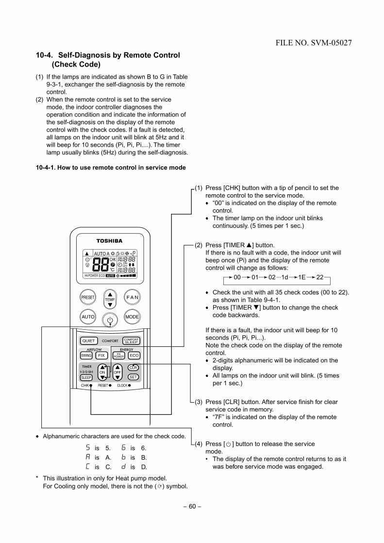
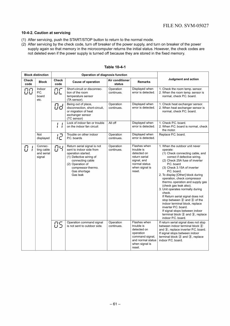
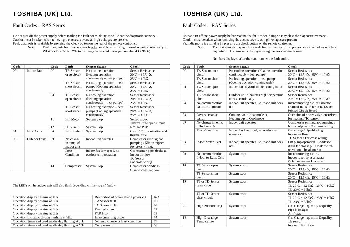
TOSHIBA (UK) Ltd. Fault Codes – RAS Series Do not turn off the power supply before reading the fault codes, doing so will clear the diagnostic memory. Caution must be taken when removing the access covers, as high voltages are present. Fault diagnosis is available by pressing the check button on the rear of the remote controller.
Note: Fault diagnosis for these systems is only possible when using infrared remote controller type WC-C2YE or WH-C2YE (which may be ordered under part number 43069666) Code Code Fault System Status Check
TA Sensor open circuit
No cooling operation (Heating operation continuously – heat pumps)
Sensor Resistance 20°C = 12.5kΩ, 25°C = 10kΩ
0C
TA Sensor short circuit
No heating operation – heat pumps (Cooling operation continuously)
Sensor Resistance 20°C = 12.5kΩ, 25°C = 10kΩ
TC Sensor open circuit
No cooling operation (Heating operation continuously – heat pumps)
Sensor Resistance 20°C = 12.5kΩ, 25°C = 10kΩ
0d
TC Sensor short circuit
No heating operation – heat pumps (Cooling operation continuously)
Sensor Resistance 20°C = 12.5kΩ, 25°C = 10kΩ
11 Fan Motor System Stop Seized motor Thermal fuse open circuit
00 Indoor Fault
12 PCB Fault System Stop Replace PCB 01 Inter. Cable 04 Inter. Cable System Stop Cable / CT termination and
thermal fuse No change in temp. of indoor unit
Indoor unit operates Compressor running not pumping / Klixon tripped. For cross wiring.
09
Frost Condition
Indoor fan low speed, no outdoor unit operation
Gas charge / pipe blockage. Indoor air flow TC Sensor For cross wiring
03 Outdoor Fault
1d Compressor System Stop Compressor windings. Current consumption.
The LED's on the indoor unit will also flash depending on the type of fault: - Operation display flashing at 1Hz Restoration of power after a power cut N/A Operation display flashing at 5Hz TA Sensor fault 0C Operation display flashing at 5Hz TC Sensor fault 0d Operation display flashing at 5Hz Fan motor fault 11 Operation display flashing at 5Hz PCB fault 12 Operation and timer display flashing at 5Hz Interconnecting cable 04 Operation, timer and pre-heat display flashing at 5Hz No temp change or frost condition 09 Operation, timer and pre-heat display flashing at 5Hz Compressor 1d
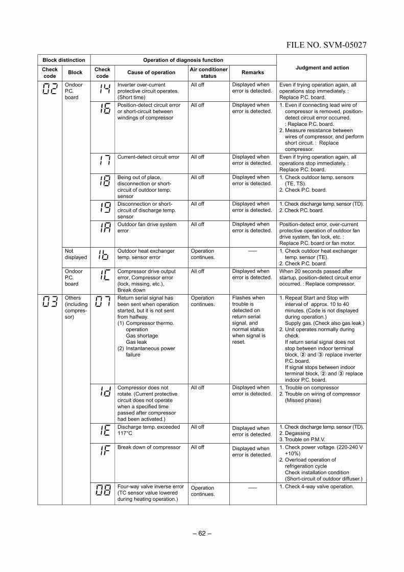
TOSHIBA (UK) Ltd. Fault Codes – RAV Series Do not turn off the power supply before reading the fault codes, doing so may clear the diagnostic memory. Caution must be taken when removing the access covers, as high voltages are present. Fault diagnosis is available by pressing the check button on the remote controller.
Note: The first number displayed is a code for the number of compressor starts the indoor unit has requested. This number is displayed using the hexadecimal format.
Numbers displayed after the start number are fault codes.
Code Fault System Status Check
TA Sensor open circuit
No cooling operation (Heating operation continuously – heat pumps)
Sensor Resistance 20°C = 12.5kΩ, 25°C = 10kΩ
0C
TA Sensor short circuit
No heating operation – heat pumps (Cooling operation continuously)
Sensor Resistance 20°C = 12.5kΩ, 25°C = 10kΩ
TC Sensor open circuit
Indoor fan stays off in the heating mode Sensor Resistance 20°C = 12.5kΩ, 25°C = 10kΩ
0d
TC Sensor short circuit
Outdoor unit simulates high temperature release continually
Sensor Resistance 20°C = 12.5kΩ, 25°C = 10kΩ
04 No communication Outdoor to Indoor
Indoor unit operates – outdoor unit does not
Interconnecting cables / isolator Outdoor transformer (240/12vac) Printed Circuit Board
08 Reverse change temp.
Cooling o/p in Heat mode or Heating o/p in Cool mode
Operation of 4 way valve, energized for heating / TC sensor
No change in temp. of indoor unit
Indoor unit operates Compressor running not pumping / Klixon tripped. / For cross wiring.
09
Frost Condition Indoor fan low speed, no outdoor unit operation
Gas charge / pipe blockage. Indoor air flow TC Sensor / For cross wiring
0b Indoor water level Indoor unit operates – outdoor unit does not
Lift pump operation. Condense drain for blockage. Floats switch operation – break on rise.
99 No communication Indoor to Rem. Con.
System stops. Interconnecting cables. Indoor is set up as a master. Only one master in a group.
TE Sensor open circuit
System stops. Sensor Resistance 20°C = 12.5kΩ, 25°C = 10kΩ
18
TE Sensor short circuit
System stops. Sensor Resistance 20°C = 12.5kΩ, 25°C = 10kΩ
TL or TD Sensor open circuit
System stops. Sensor Resistance TL 20°C = 12.5kΩ, 25°C = 10kΩ TD 23°C = 53kΩ
19
TL or TD Sensor short circuit
System stops. Sensor Resistance TL 20°C = 12.5kΩ, 25°C = 10kΩ TD 23°C = 53kΩ
21 High Pressure Trip System stops. Gas Charge – quantity & quality Pipe blockages Air flows
1E High Discharge Temperature
System stops. Gas Charge – quantity & quality TE sensor Indoor unit air flow
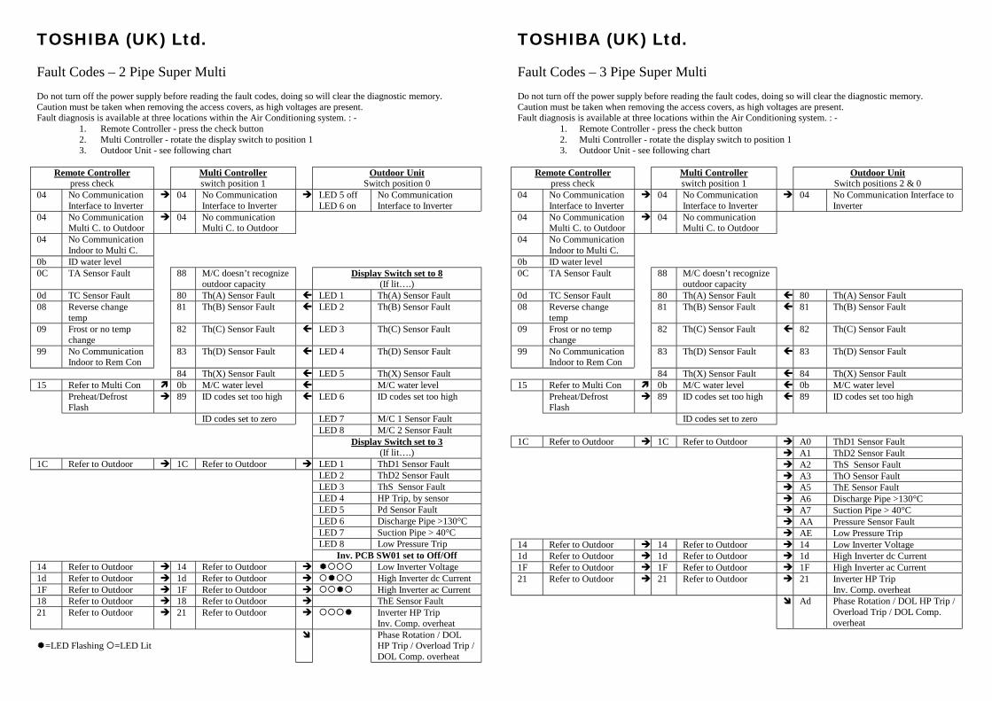
TOSHIBA (UK) Ltd. Fault Codes – 2 Pipe Super Multi Do not turn off the power supply before reading the fault codes, doing so will clear the diagnostic memory. Caution must be taken when removing the access covers, as high voltages are present. Fault diagnosis is available at three locations within the Air Conditioning system. : -
1. Remote Controller - press the check button 2. Multi Controller - rotate the display switch to position 1 3. Outdoor Unit - see following chart
Remote Controller
press check Multi Controller
switch position 1 Outdoor Unit
Switch position 0 04 No Communication
Interface to Inverter " 04 No Communication
Interface to Inverter " LED 5 off
LED 6 on No Communication Interface to Inverter
04 No Communication Multi C. to Outdoor
" 04 No communication Multi C. to Outdoor
04 No Communication Indoor to Multi C.
0b ID water level
0C TA Sensor Fault 88 M/C doesn’t recognize outdoor capacity
Display Switch set to 8 (If lit….)
0d TC Sensor Fault 80 Th(A) Sensor Fault # LED 1 Th(A) Sensor Fault 08 Reverse change
temp 81 Th(B) Sensor Fault # LED 2 Th(B) Sensor Fault
09 Frost or no temp change
82 Th(C) Sensor Fault # LED 3 Th(C) Sensor Fault
99 No Communication Indoor to Rem Con
83 Th(D) Sensor Fault # LED 4 Th(D) Sensor Fault
84 Th(X) Sensor Fault # LED 5 Th(X) Sensor Fault 15 Refer to Multi Con $ 0b M/C water level # M/C water level Preheat/Defrost
Flash " 89 ID codes set too high # LED 6 ID codes set too high
ID codes set to zero LED 7 M/C 1 Sensor Fault LED 8 M/C 2 Sensor Fault
Display Switch set to 3 (If lit….)
1C Refer to Outdoor " 1C Refer to Outdoor " LED 1 ThD1 Sensor Fault LED 2 ThD2 Sensor Fault LED 3 ThS Sensor Fault LED 4 HP Trip, by sensor LED 5 Pd Sensor Fault LED 6 Discharge Pipe >130°C LED 7 Suction Pipe > 40°C LED 8 Low Pressure Trip
Inv. PCB SW01 set to Off/Off 14 Refer to Outdoor " 14 Refer to Outdoor " %&&& Low Inverter Voltage 1d Refer to Outdoor " 1d Refer to Outdoor " &%&& High Inverter dc Current 1F Refer to Outdoor " 1F Refer to Outdoor " &&%& High Inverter ac Current 18 Refer to Outdoor " 18 Refer to Outdoor " ThE Sensor Fault 21 Refer to Outdoor " 21 Refer to Outdoor " &&&% Inverter HP Trip
Inv. Comp. overheat %=LED Flashing &=LED Lit
' Phase Rotation / DOL HP Trip / Overload Trip / DOL Comp. overheat
TOSHIBA (UK) Ltd. Fault Codes – 3 Pipe Super Multi Do not turn off the power supply before reading the fault codes, doing so will clear the diagnostic memory. Caution must be taken when removing the access covers, as high voltages are present. Fault diagnosis is available at three locations within the Air Conditioning system. : -
1. Remote Controller - press the check button 2. Multi Controller - rotate the display switch to position 1 3. Outdoor Unit - see following chart
Remote Controller
press check Multi Controller
switch position 1 Outdoor Unit
Switch positions 2 & 0 04 No Communication
Interface to Inverter " 04 No Communication
Interface to Inverter " 04 No Communication Interface to
Inverter 04 No Communication
Multi C. to Outdoor " 04 No communication
Multi C. to Outdoor
04 No Communication Indoor to Multi C.
0b ID water level
0C TA Sensor Fault 88 M/C doesn’t recognize outdoor capacity
0d TC Sensor Fault 80 Th(A) Sensor Fault # 80 Th(A) Sensor Fault 08 Reverse change
temp 81 Th(B) Sensor Fault # 81 Th(B) Sensor Fault
09 Frost or no temp change
82 Th(C) Sensor Fault # 82 Th(C) Sensor Fault
99 No Communication Indoor to Rem Con
83 Th(D) Sensor Fault # 83 Th(D) Sensor Fault
84 Th(X) Sensor Fault # 84 Th(X) Sensor Fault 15 Refer to Multi Con $ 0b M/C water level # 0b M/C water level Preheat/Defrost
Flash " 89 ID codes set too high # 89 ID codes set too high
ID codes set to zero 1C Refer to Outdoor " 1C Refer to Outdoor " A0 ThD1 Sensor Fault
" A1 ThD2 Sensor Fault " A2 ThS Sensor Fault " A3 ThO Sensor Fault " A5 ThE Sensor Fault " A6 Discharge Pipe >130°C " A7 Suction Pipe > 40°C " AA Pressure Sensor Fault
" AE Low Pressure Trip 14 Refer to Outdoor " 14 Refer to Outdoor " 14 Low Inverter Voltage 1d Refer to Outdoor " 1d Refer to Outdoor " 1d High Inverter dc Current 1F Refer to Outdoor " 1F Refer to Outdoor " 1F High Inverter ac Current 21 Refer to Outdoor " 21 Refer to Outdoor " 21 Inverter HP Trip
Inv. Comp. overheat ' Ad Phase Rotation / DOL HP Trip /
Overload Trip / DOL Comp. overheat

133
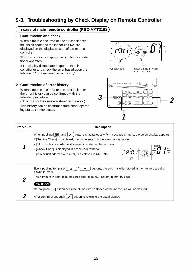
9-3. Troubleshooting by Check Display on Remote Controller
In case of main remote controller (RBC-AMT21E)
UNIT No.
CODE No.
R.C. No.
Check code Indoor unit No. in which an error occurred
UNIT
SET CL
3 2
1Procedure
1
2
3
Description
When pushing SET and buttons simultaneously for 4 seconds or more, the below display appears.
If [Service Check] is displayed, the mode enters in the error history mode.
• [01: Error history order] is displayed in code number window.
• [Check Code] is displayed in check code window.
• [Indoor unit address with error] is displayed in UNIT No.
Every pushing temp. set / buttons, the error histories stored in the memory are dis-played in order.
The numbers in item code indicates item code [01] (Latest) to [04] (Oldest).
CAUTION
Do not push [CL] button because all the error histories of the indoor unit will be deleted.
After confirmation, push button to return to the usual display.
UNIT No.
CODE No.
R.C. No.
1. Confirmation and checkWhen a trouble occurred on the air conditioner,the check code and the indoor unit No. aredisplayed on the display section of the remotecontroller.
The check code is displayed while the air condi-tioner operates.
If the display disappeared, operate the airconditioner and check the error based upon thefollowing “Confirmation of error history”.
2. Confirmation of error historyWhen a trouble occurred on the air conditioner,the error history can be confirmed with thefollowing procedure.(Up to 4 error histories are stored in memory.)
This history can be confirmed from either operat-ing status or stop status.

134
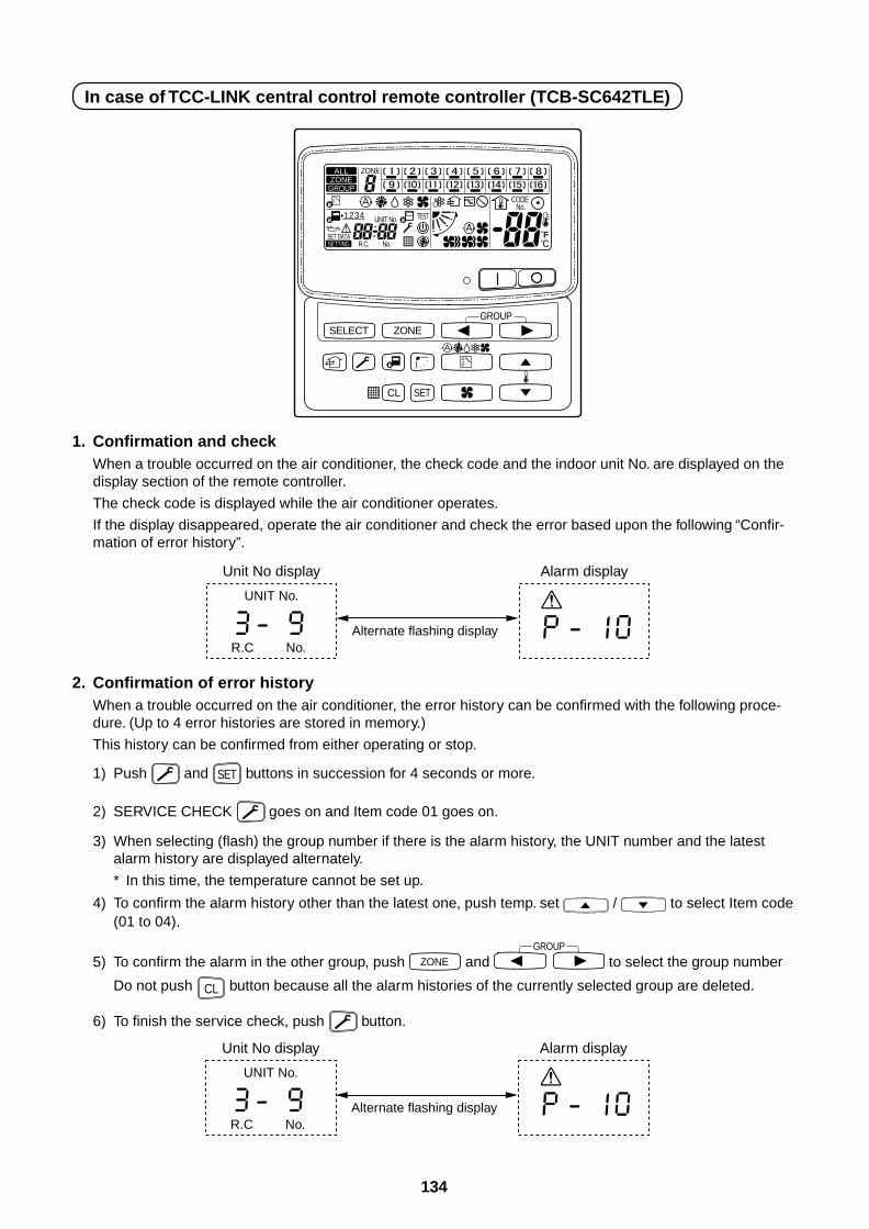
In case of TCC-LINK central control remote controller (TCB-SC642TLE)
1. Confirmation and checkWhen a trouble occurred on the air conditioner, the check code and the indoor unit No. are displayed on thedisplay section of the remote controller.
The check code is displayed while the air conditioner operates.
If the display disappeared, operate the air conditioner and check the error based upon the following “Confir-mation of error history”.
UNIT No.
Alternate flashing displayR.C No.
Unit No display Alarm display
SELECT ZONE
CL SET
GROUP
CODE No.
UNIT No.
No.R.C.
TEST
ZONEALLZONE
GROUP
SETTING
1234
SET DATA
2. Confirmation of error historyWhen a trouble occurred on the air conditioner, the error history can be confirmed with the following proce-dure. (Up to 4 error histories are stored in memory.)
This history can be confirmed from either operating or stop.
1) Push and SET buttons in succession for 4 seconds or more.
2) SERVICE CHECK goes on and Item code 01 goes on.
3) When selecting (flash) the group number if there is the alarm history, the UNIT number and the latestalarm history are displayed alternately.
* In this time, the temperature cannot be set up.
4) To confirm the alarm history other than the latest one, push temp. set / to select Item code(01 to 04).
5) To confirm the alarm in the other group, push ZONE and GROUP
to select the group number
Do not push CL button because all the alarm histories of the currently selected group are deleted.
6) To finish the service check, push button.
UNIT No.
Alternate flashing displayR.C No.
Unit No display Alarm display
– 81 –
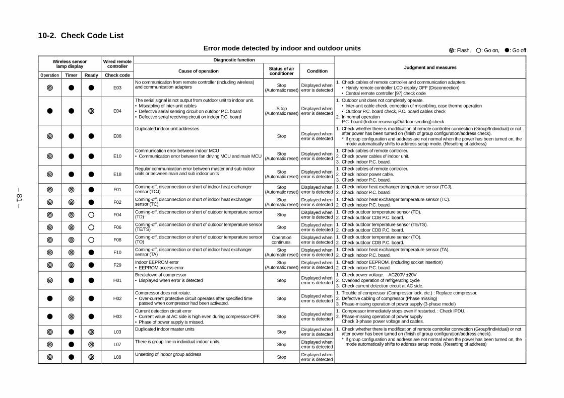
10-2. Check Code List
Error mode detected by indoor and outdoor units : Flash, : Go on, : Go off
Diagnostic functionWireless sensorlamp display
Wired remotecontroller
Operation Timer Ready Check codeCause of operation Status of air
conditioner ConditionJudgment and measures
E03No communication from remote controller (including wireless)and communication adapters Stop
(Automatic reset)Displayed whenerror is detected
1. Check cables of remote controller and communication adapters.• Handy remote controller LCD display OFF (Disconnection)• Central remote controller [97] check code
E04
The serial signal is not output from outdoor unit to indoor unit.• Miscabling of inter-unit cables• Defective serial sensing circuit on outdoor P.C. board• Defective serial receiving circuit on indoor P.C. board
S top(Automatic reset)
Displayed whenerror is detected
1. Outdoor unit does not completely operate.• Inter-unit cable check, correction of miscabling, case thermo operation• Outdoor P.C. board check, P.C. board cables check
2. In normal operationP.C. board (Indoor receiving/Outdoor sending) check
E08
Duplicated indoor unit addresses
Stop Displayed whenerror is detected
1. Check whether there is modification of remote controller connection (Group/Individual) or notafter power has been turned on (finish of group configuration/address check).* If group configuration and address are not normal when the power has been turned on, the
mode automatically shifts to address setup mode. (Resetting of address)
E10Communication error between indoor MCU• Communication error between fan driving MCU and main MCU Stop
(Automatic reset)Displayed whenerror is detected
1. Check cables of remote controller.2. Check power cables of indoor unit.3. Check indoor P.C. board.
E18Regular communication error between master and sub indoorunits or between main and sub indoor units Stop
(Automatic reset)Displayed whenerror is detected
1. Check cables of remote controller.2. Check indoor power cable.3. Check indoor P.C. board.
F01Coming-off, disconnection or short of indoor heat exchangersensor (TCJ)
Stop(Automatic reset)
Displayed whenerror is detected
1. Check indoor heat exchanger temperature sensor (TCJ).2. Check indoor P.C. board.
F02Coming-off, disconnection or short of indoor heat exchangersensor (TC)
Stop(Automatic reset)
Displayed whenerror is detected
1. Check indoor heat exchanger temperature sensor (TC).2. Check indoor P.C. board.
F04Coming-off, disconnection or short of outdoor temperature sensor(TD) Stop Displayed when
error is detected1. Check outdoor temperature sensor (TD).2. Check outdoor CDB P.C. board.
F06Coming-off, disconnection or short of outdoor temperature sensor(TE/TS) Stop Displayed when
error is detected1. Check outdoor temperature sensor (TE/TS).2. Check outdoor CDB P.C. board.
F08Coming-off, disconnection or short of outdoor temperature sensor(TO)
Operationcontinues.
Displayed whenerror is detected
1. Check outdoor temperature sensor (TO).2. Check outdoor CDB P.C. board.
F10Coming-off, disconnection or short of indoor heat exchangersensor (TA)
Stop(Automatic reset)
Displayed whenerror is detected
1. Check indoor heat exchanger temperature sensor (TA).2. Check indoor P.C. board.
F29Indoor EEPROM error• EEPROM access error
Stop(Automatic reset)
Displayed whenerror is detected
1. Check indoor EEPROM. (including socket insertion)2. Check indoor P.C. board.
H01Breakdown of compressor• Displayed when error is detected Stop Displayed when
error is detected
1. Check power voltage. AC200V ±20V2. Overload operation of refrigerating cycle3. Check current detection circuit at AC side.
H02Compressor does not rotate.• Over-current protective circuit operates after specified time
passed when compressor had been activated.Stop Displayed when
error is detected
1. Trouble of compressor (Compressor lock, etc.) : Replace compressor.2. Defective cabling of compressor (Phase missing)3. Phase-missing operation of power supply (3-phase model)
H03Current detection circuit error• Current value at AC side is high even during compressor-OFF.• Phase of power supply is missed.
Stop Displayed whenerror is detected
1. Compressor immediately stops even if restarted. : Check IPDU.2. Phase-missing operation of power supply
Check 3-phase power voltage and cables.
L03Duplicated indoor master units
Stop Displayed whenerror is detected
L07There is group line in individual indoor units.
Stop Displayed whenerror is detected
L08Unsetting of indoor group address
Stop Displayed whenerror is detected
1. Check whether there is modification of remote controller connection (Group/Individual) or notafter power has been turned on (finish of group configuration/address check).* If group configuration and address are not normal when the power has been turned on, the
mode automatically shifts to address setup mode. (Resetting of address)
– 82 –
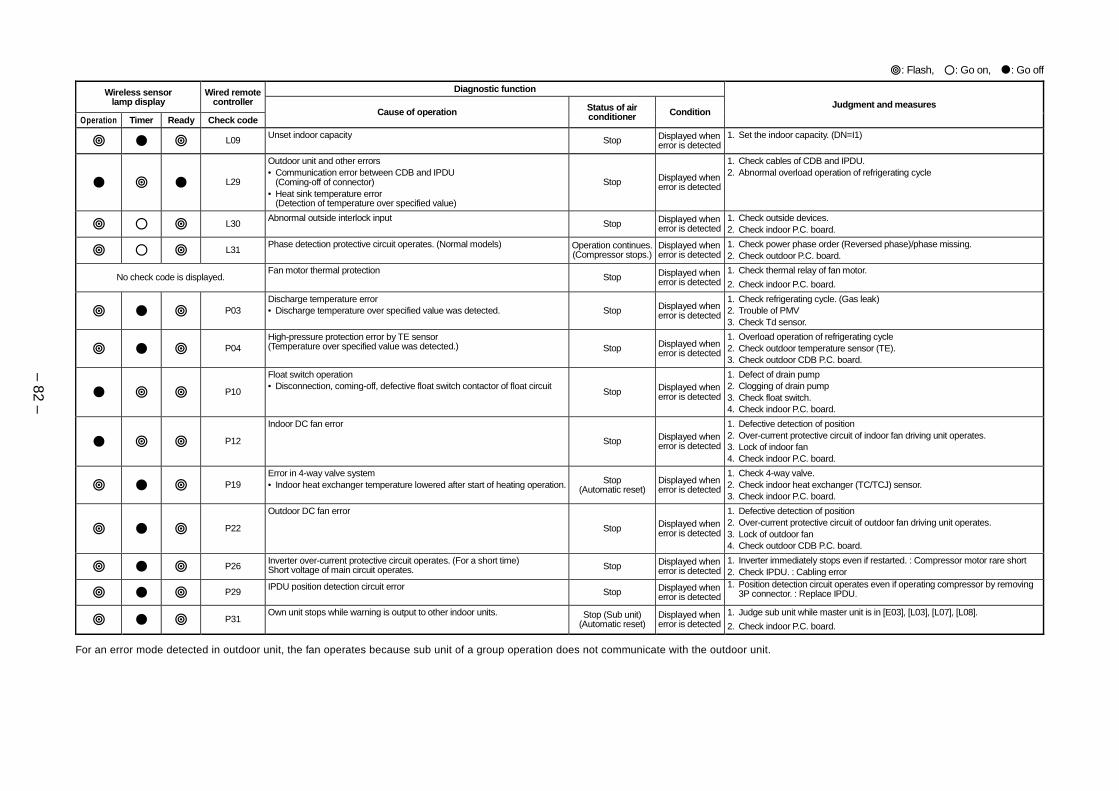
For an error mode detected in outdoor unit, the fan operates because sub unit of a group operation does not communicate with the outdoor unit.
: Flash, : Go on, : Go off
Diagnostic functionWireless sensorlamp display
Wired remotecontroller
Operation Timer Ready Check codeCause of operation Status of air
conditioner ConditionJudgment and measures
L09Unset indoor capacity
Stop Displayed whenerror is detected
1. Set the indoor capacity. (DN=I1)
L29
Outdoor unit and other errors• Communication error between CDB and IPDU
(Coming-off of connector)• Heat sink temperature error
(Detection of temperature over specified value)
Stop Displayed whenerror is detected
1. Check cables of CDB and IPDU.2. Abnormal overload operation of refrigerating cycle
L30Abnormal outside interlock input
Stop Displayed whenerror is detected
1. Check outside devices.2. Check indoor P.C. board.
L31Phase detection protective circuit operates. (Normal models) Operation continues.
(Compressor stops.)Displayed whenerror is detected
1. Check power phase order (Reversed phase)/phase missing.2. Check outdoor P.C. board.
No check code is displayed.Fan motor thermal protection
Stop Displayed whenerror is detected
1. Check thermal relay of fan motor.
2. Check indoor P.C. board.
P03Discharge temperature error• Discharge temperature over specified value was detected. Stop Displayed when
error is detected
1. Check refrigerating cycle. (Gas leak)2. Trouble of PMV3. Check Td sensor.
P04High-pressure protection error by TE sensor(Temperature over specified value was detected.) Stop Displayed when
error is detected
1. Overload operation of refrigerating cycle2. Check outdoor temperature sensor (TE).3. Check outdoor CDB P.C. board.
P10
Float switch operation• Disconnection, coming-off, defective float switch contactor of float circuit
Stop Displayed whenerror is detected
1. Defect of drain pump2. Clogging of drain pump3. Check float switch.4. Check indoor P.C. board.
P12
Indoor DC fan error
Stop Displayed whenerror is detected
1. Defective detection of position2. Over-current protective circuit of indoor fan driving unit operates.3. Lock of indoor fan4. Check indoor P.C. board.
P19Error in 4-way valve system• Indoor heat exchanger temperature lowered after start of heating operation. Stop
(Automatic reset)Displayed whenerror is detected
1. Check 4-way valve.2. Check indoor heat exchanger (TC/TCJ) sensor.3. Check indoor P.C. board.
P22
Outdoor DC fan error
Stop Displayed whenerror is detected
1. Defective detection of position2. Over-current protective circuit of outdoor fan driving unit operates.3. Lock of outdoor fan4. Check outdoor CDB P.C. board.
P26Inverter over-current protective circuit operates. (For a short time)Short voltage of main circuit operates. Stop Displayed when
error is detected1. Inverter immediately stops even if restarted. : Compressor motor rare short2. Check IPDU. : Cabling error
P29IPDU position detection circuit error
Stop Displayed whenerror is detected
1. Position detection circuit operates even if operating compressor by removing3P connector. : Replace IPDU.
P31Own unit stops while warning is output to other indoor units. Stop (Sub unit)
(Automatic reset)Displayed whenerror is detected
1. Judge sub unit while master unit is in [E03], [L03], [L07], [L08].
2. Check indoor P.C. board.
– 83 –
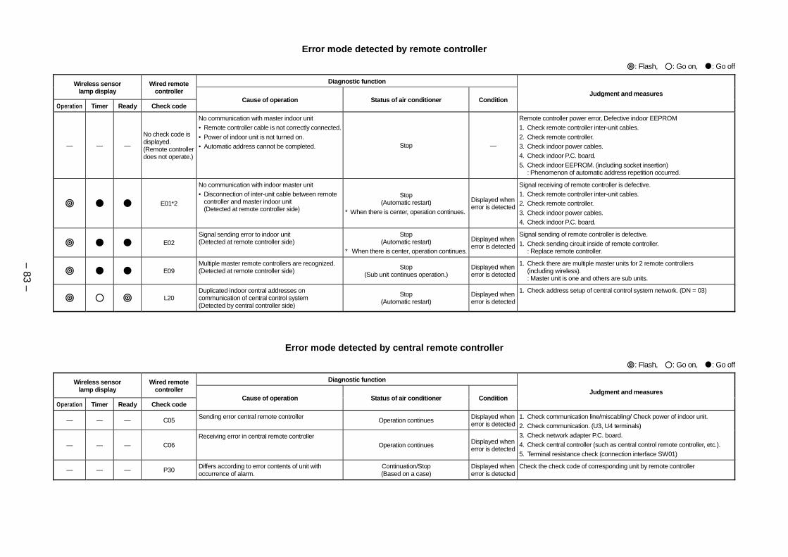
Error mode detected by remote controller
: Flash, : Go on, : Go off
Diagnostic functionWireless sensorlamp display
Wired remotecontroller
Operation Timer Ready Check codeCause of operation Status of air conditioner Condition
Judgment and measures
— — —
No check code isdisplayed.(Remote controllerdoes not operate.)
No communication with master indoor unit• Remote controller cable is not correctly connected.
• Power of indoor unit is not turned on.• Automatic address cannot be completed. Stop —
Remote controller power error, Defective indoor EEPROM1. Check remote controller inter-unit cables.
2. Check remote controller.3. Check indoor power cables.4. Check indoor P.C. board.
5. Check indoor EEPROM. (including socket insertion): Phenomenon of automatic address repetition occurred.
E01*2
No communication with indoor master unit• Disconnection of inter-unit cable between remote
controller and master indoor unit(Detected at remote controller side)
Stop(Automatic restart)
* When there is center, operation continues.
Displayed whenerror is detected
Signal receiving of remote controller is defective.1. Check remote controller inter-unit cables.2. Check remote controller.
3. Check indoor power cables.4. Check indoor P.C. board.
E02Signal sending error to indoor unit(Detected at remote controller side)
Stop(Automatic restart)
* When there is center, operation continues.
Displayed whenerror is detected
Signal sending of remote controller is defective.
1. Check sending circuit inside of remote controller.: Replace remote controller.
E09Multiple master remote controllers are recognized.(Detected at remote controller side) Stop
(Sub unit continues operation.)Displayed whenerror is detected
1. Check there are multiple master units for 2 remote controllers(including wireless).: Master unit is one and others are sub units.
L20Duplicated indoor central addresses oncommunication of central control system(Detected by central controller side)
Stop(Automatic restart)
Displayed whenerror is detected
1. Check address setup of central control system network. (DN = 03)
: Flash, : Go on, : Go off
Diagnostic functionWireless sensorlamp display
Wired remotecontroller
Operation Timer Ready Check codeCause of operation Status of air conditioner Condition
Judgment and measures
— — — C05 Sending error central remote controller Operation continues Displayed whenerror is detected
— — — C06Receiving error in central remote controller
Operation continues Displayed whenerror is detected
1. Check communication line/miscabling/ Check power of indoor unit.2. Check communication. (U3, U4 terminals)
3. Check network adapter P.C. board.4. Check central controller (such as central control remote controller, etc.).5. Terminal resistance check (connection interface SW01)
— — — P30 Differs according to error contents of unit withoccurrence of alarm.
Continuation/Stop(Based on a case)
Displayed whenerror is detected
Check the check code of corresponding unit by remote controller
Error mode detected by central remote controller
– 84 –
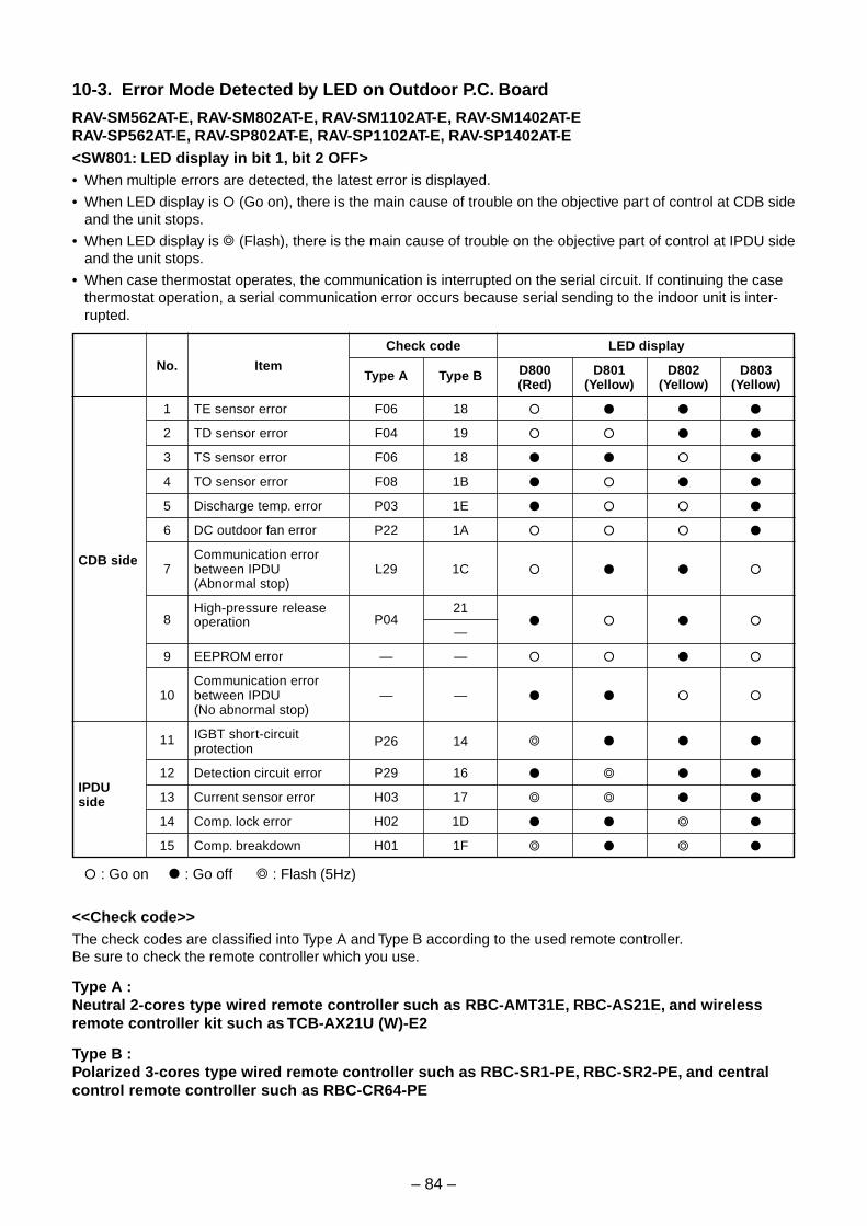
10-3. Error Mode Detected by LED on Outdoor P.C. Board
RAV-SM562AT-E, RAV-SM802AT-E, RAV-SM1102AT-E, RAV-SM1402AT-ERAV-SP562AT-E, RAV-SP802AT-E, RAV-SP1102AT-E, RAV-SP1402AT-E<SW801: LED display in bit 1, bit 2 OFF>• When multiple errors are detected, the latest error is displayed.
• When LED display is (Go on), there is the main cause of trouble on the objective part of control at CDB sideand the unit stops.
• When LED display is (Flash), there is the main cause of trouble on the objective part of control at IPDU sideand the unit stops.
• When case thermostat operates, the communication is interrupted on the serial circuit. If continuing the casethermostat operation, a serial communication error occurs because serial sending to the indoor unit is inter-rupted.
CDB side
IPDUside
No.
1
2
3
4
5
6
7
8
9
10
11
12
13
14
15
Item
TE sensor error
TD sensor error
TS sensor error
TO sensor error
Discharge temp. error
DC outdoor fan error
Communication errorbetween IPDU(Abnormal stop)
High-pressure releaseoperation
EEPROM error
Communication errorbetween IPDU(No abnormal stop)
IGBT short-circuitprotection
Detection circuit error
Current sensor error
Comp. lock error
Comp. breakdown
Check code
Type A Type B
F06 18
F04 19
F06 18
F08 1B
P03 1E
P22 1A
L29 1C
P0421
—
— —
— —
P26 14
P29 16
H03 17
H02 1D
H01 1F
LED display
D800 D801 D802 D803(Red) (Yellow) (Yellow) (Yellow)
: Go on : Go off : Flash (5Hz)
<<Check code>>The check codes are classified into Type A and Type B according to the used remote controller.Be sure to check the remote controller which you use.
Type A :Neutral 2-cores type wired remote controller such as RBC-AMT31E, RBC-AS21E, and wirelessremote controller kit such as TCB-AX21U (W)-E2
Type B :Polarized 3-cores type wired remote controller such as RBC-SR1-PE, RBC-SR2-PE, and centralcontrol remote controller such as RBC-CR64-PE
133
9-3. Troubleshooting by Check Display on Remote Controller
In case of main remote controller (RBC-AMT21E)
UNIT No.
CODE No.
R.C. No.
Check code Indoor unit No. in which an error occurred
UNIT
SET CL
3 2
1Procedure
1
2
3
Description
When pushing SET and buttons simultaneously for 4 seconds or more, the below display appears.
If [Service Check] is displayed, the mode enters in the error history mode.
• [01: Error history order] is displayed in code number window.
• [Check Code] is displayed in check code window.
• [Indoor unit address with error] is displayed in UNIT No.
Every pushing temp. set / buttons, the error histories stored in the memory are dis-played in order.
The numbers in item code indicates item code [01] (Latest) to [04] (Oldest).
CAUTION
Do not push [CL] button because all the error histories of the indoor unit will be deleted.
After confirmation, push button to return to the usual display.
UNIT No.
CODE No.
R.C. No.
1. Confirmation and checkWhen a trouble occurred on the air conditioner,the check code and the indoor unit No. aredisplayed on the display section of the remotecontroller.
The check code is displayed while the air condi-tioner operates.
If the display disappeared, operate the airconditioner and check the error based upon thefollowing “Confirmation of error history”.
2. Confirmation of error historyWhen a trouble occurred on the air conditioner,the error history can be confirmed with thefollowing procedure.(Up to 4 error histories are stored in memory.)
This history can be confirmed from either operat-ing status or stop status.
134
In case of TCC-LINK central control remote controller (TCB-SC642TLE)
1. Confirmation and checkWhen a trouble occurred on the air conditioner, the check code and the indoor unit No. are displayed on thedisplay section of the remote controller.
The check code is displayed while the air conditioner operates.
If the display disappeared, operate the air conditioner and check the error based upon the following “Confir-mation of error history”.
UNIT No.
Alternate flashing displayR.C No.
Unit No display Alarm display
SELECT ZONE
CL SET
GROUP
CODE No.
UNIT No.
No.R.C.
TEST
ZONEALLZONE
GROUP
SETTING
1234
SET DATA
2. Confirmation of error historyWhen a trouble occurred on the air conditioner, the error history can be confirmed with the following proce-dure. (Up to 4 error histories are stored in memory.)
This history can be confirmed from either operating or stop.
1) Push and SET buttons in succession for 4 seconds or more.
2) SERVICE CHECK goes on and Item code 01 goes on.
3) When selecting (flash) the group number if there is the alarm history, the UNIT number and the latestalarm history are displayed alternately.
* In this time, the temperature cannot be set up.
4) To confirm the alarm history other than the latest one, push temp. set / to select Item code(01 to 04).
5) To confirm the alarm in the other group, push ZONE and GROUP
to select the group number
Do not push CL button because all the alarm histories of the currently selected group are deleted.
6) To finish the service check, push button.
UNIT No.
Alternate flashing displayR.C No.
Unit No display Alarm display
136
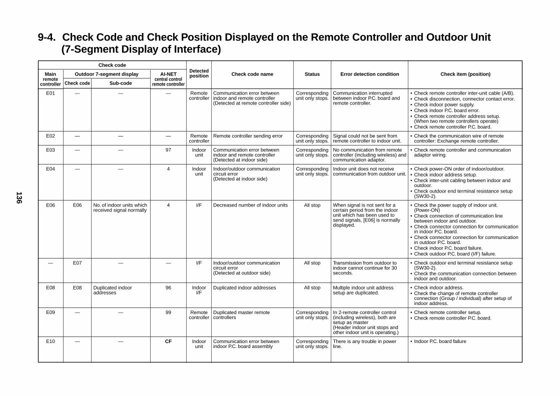
9-4. Check Code and Check Position Displayed on the Remote Controller and Outdoor Unit(7-Segment Display of Interface)
Check code
Mainremote
controller
E01
E02
E03
E04
E06
—
E08
E09
E10
Outdoor 7-segment display
Check code Sub-code
— —
— —
— —
— —
E06 No. of indoor units whichreceived signal normally
E07 —
E08 Duplicated indooraddresses
— —
— —
AI-NETcentral control
remote controller
—
—
97
4
4
—
96
99
CF
Detectedposition
Remotecontroller
Remotecontroller
Indoorunit
Indoorunit
I/F
I/F
IndoorI/F
Remotecontroller
Indoorunit
Check code name
Communication error betweenindoor and remote controller(Detected at remote controller side)
Remote controller sending error
Communication error betweenindoor and remote controller(Detected at indoor side)
Indoor/outdoor communicationcircuit error(Detected at indoor side)
Decreased number of indoor units
Indoor/outdoor communicationcircuit error(Detected at outdoor side)
Duplicated indoor addresses
Duplicated master remotecontrollers
Communication error betweenindoor P.C. board assembly
Status
Correspondingunit only stops.
Correspondingunit only stops.
Correspondingunit only stops.
Correspondingunit only stops.
All stop
All stop
All stop
Correspondingunit only stops.
Correspondingunit only stops.
Error detection condition
Communication interruptedbetween indoor P.C. board andremote controller.
Signal could not be sent fromremote controller to indoor unit.
No communication from remotecontroller (including wireless) andcommunication adaptor.
Indoor unit does not receivecommunication from outdoor unit.
When signal is not sent for acertain period from the indoorunit which has been used tosend signals, [E06] is normallydisplayed.
Transmission from outdoor toindoor cannot continue for 30seconds.
Multiple indoor unit addresssetup are duplicated.
In 2-remote controller control(including wireless), both aresetup as master(Header indoor unit stops andother indoor unit is operating.)
There is any trouble in powerline.
Check item (position)
• Check remote controller inter-unit cable (A/B).• Check disconnection, connector contact error.• Check indoor power supply.• Check indoor P.C. board error.• Check remote controller address setup.
(When two remote controllers operate)• Check remote controller P.C. board.
• Check the communication wire of remotecontroller: Exchange remote controller.
• Check remote controller and communicationadaptor wiring.
• Check power-ON order of indoor/outdoor.• Check indoor address setup.• Check inter-unit cabling between indoor and
outdoor.• Check outdoor end terminal resistance setup
(SW30-2).
• Check the power supply of indoor unit.(Power-ON)
• Check connection of communication linebetween indoor and outdoor.
• Check connector connection for communicationin indoor P.C. board.
• Check connector connection for communicationin outdoor P.C. board.
• Check indoor P.C. board failure.• Check outdoor P.C. board (I/F) failure.
• Check outdoor end terminal resistance setup(SW30-2).
• Check the communication connection betweenindoor and outdoor.
• Check indoor address.• Check the change of remote controller
connection (Group / individual) after setup ofindoor address.
• Check remote controller setup.• Check remote controller P.C. board.
• Indoor P.C. board failure
137
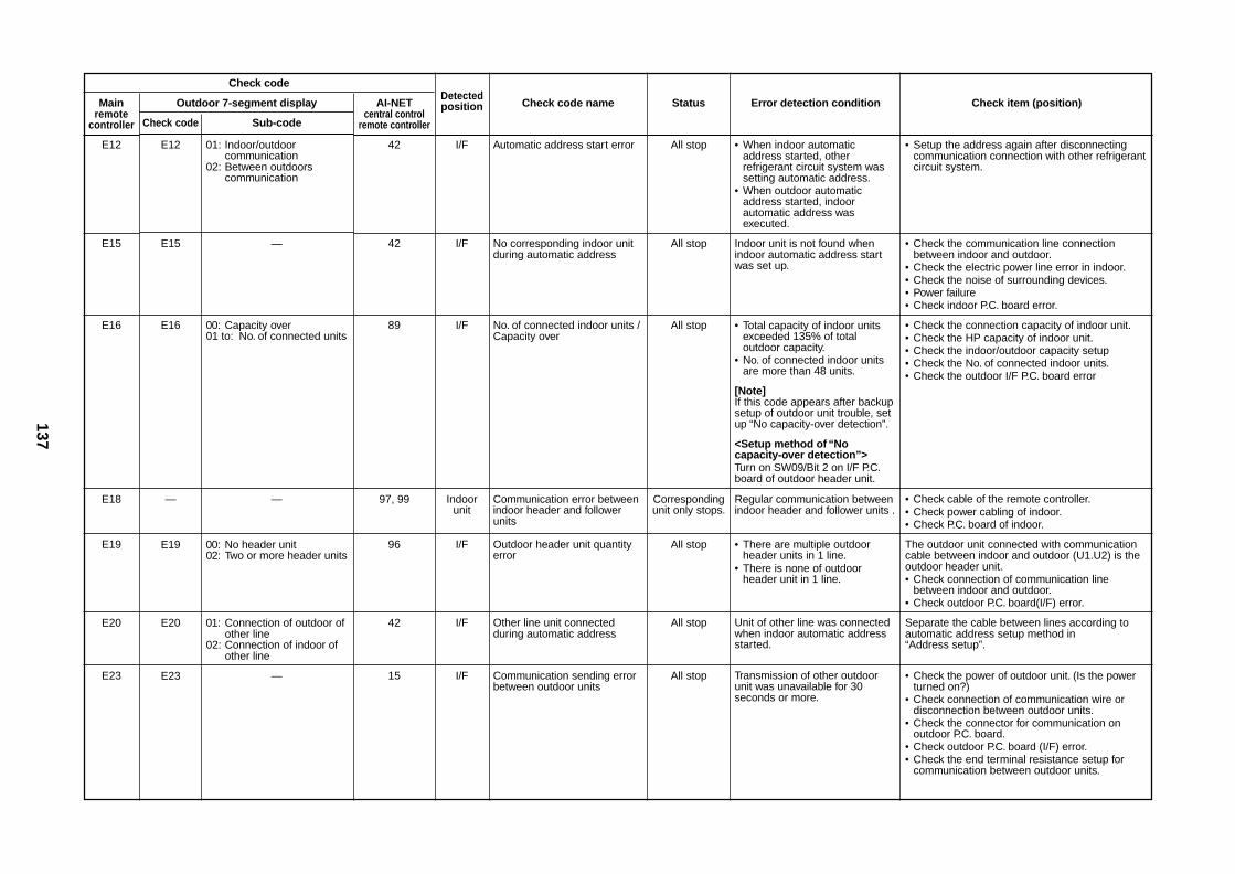
Check code
Mainremote
controller
E12
E15
E16
E18
E19
E20
E23
Outdoor 7-segment display
Check code Sub-code
E12 01: Indoor/outdoorcommunication
02: Between outdoorscommunication
E15 —
E16 00: Capacity over01 to: No. of connected units
— —
E19 00: No header unit02: Two or more header units
E20 01: Connection of outdoor ofother line
02: Connection of indoor ofother line
E23 —
AI-NETcentral control
remote controller
42
42
89
97, 99
96
42
15
Detectedposition
I/F
I/F
I/F
Indoorunit
I/F
I/F
I/F
Check code name
Automatic address start error
No corresponding indoor unitduring automatic address
No. of connected indoor units /Capacity over
Communication error betweenindoor header and followerunits
Outdoor header unit quantityerror
Other line unit connectedduring automatic address
Communication sending errorbetween outdoor units
Status
All stop
All stop
All stop
Correspondingunit only stops.
All stop
All stop
All stop
Error detection condition
• When indoor automaticaddress started, otherrefrigerant circuit system wassetting automatic address.
• When outdoor automaticaddress started, indoorautomatic address wasexecuted.
Indoor unit is not found whenindoor automatic address startwas set up.
• Total capacity of indoor unitsexceeded 135% of totaloutdoor capacity.
• No. of connected indoor unitsare more than 48 units.
[Note]If this code appears after backupsetup of outdoor unit trouble, setup “No capacity-over detection”.
<Setup method of “Nocapacity-over detection”>Turn on SW09/Bit 2 on I/F P.C.board of outdoor header unit.
Regular communication betweenindoor header and follower units .
• There are multiple outdoorheader units in 1 line.
• There is none of outdoorheader unit in 1 line.
Unit of other line was connectedwhen indoor automatic addressstarted.
Transmission of other outdoorunit was unavailable for 30seconds or more.
Check item (position)
• Setup the address again after disconnectingcommunication connection with other refrigerantcircuit system.
• Check the communication line connectionbetween indoor and outdoor.
• Check the electric power line error in indoor.• Check the noise of surrounding devices.• Power failure• Check indoor P.C. board error.
• Check the connection capacity of indoor unit.• Check the HP capacity of indoor unit.• Check the indoor/outdoor capacity setup• Check the No. of connected indoor units.• Check the outdoor I/F P.C. board error
• Check cable of the remote controller.• Check power cabling of indoor.• Check P.C. board of indoor.
The outdoor unit connected with communicationcable between indoor and outdoor (U1.U2) is theoutdoor header unit.• Check connection of communication line
between indoor and outdoor.• Check outdoor P.C. board(I/F) error.
Separate the cable between lines according toautomatic address setup method in“Address setup”.
• Check the power of outdoor unit. (Is the powerturned on?)
• Check connection of communication wire ordisconnection between outdoor units.
• Check the connector for communication onoutdoor P.C. board.
• Check outdoor P.C. board (I/F) error.• Check the end terminal resistance setup for
communication between outdoor units.
138
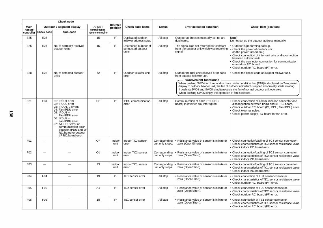
Check code
Mainremote
controller
E25
E26
E28
E31
F01
F02
F03
F04
F05
F06
Outdoor 7-segment display
Check code Sub-code
E25 —
E26 No. of normally receivedoutdoor units
E28 No. of detected outdoorunits
E31 01: IPDU1 error02: IPDU2 error03: IPDU1, 2 errors04: Fan IPDU error05: IPDU1 +
Fan IPDU error06: IPDU2 +
Fan IPDU error07: All IPDU error or
communication errorbetween IPDU and I/FP.C. board or outdoorI/F P.C. board error
— —
— —
— —
F04 —
F05 —
F06 —
AI-NETcentral control
remote controller
15
15
d2
CF
OF
Od
93
19
A1
18
Detectedposition
I/F
I/F
I/F
I/F
Indoorunit
Indoorunit
Indoorunit
I/F
I/F
I/F
Check code name
Duplicated outdoorfollower address setup
Decreased number ofconnected outdoorunits
Outdoor follower uniterror
IPDU communicationerror
Indoor TCJ sensorerror
Indoor TC2 sensorerror
Indoor TC1 sensorerror
TD1 sensor error
TD2 sensor error
TE1 sensor error
Status
All stop
All stop
All stop
All stop
Correspondingunit only stops.
Correspondingunit only stops.
Correspondingunit only stops.
All stop
All stop
All stop
Error detection condition
Outdoor addresses manually set up areduplicated.
The signal was not returned for constantfrom the outdoor unit which was receivingsignal.
Outdoor header unit received error codefrom outdoor follower unit.
Communication of each IPDU (P.C.board) in inverter box interrupted.
• Resistance value of sensor is infinite orzero. (Open/Short)
• Resistance value of sensor is infinite orzero (Open/Short).
• Resistance value of sensor is infinite orzero (Open/Short).
• Resistance value of sensor is infinite orzero (Open/Short).
• Resistance value of sensor is infinite orzero (Open/Short).
• Resistance value of sensor is infinite orzero (Open/Short).
Check item (position)
Note)Do not set up the outdoor address manually.
• Outdoor is performing backup.• Check the power of outdoor unit.
(Is the power turned on?)• Check connection of inter-unit wire or disconnection
between outdoor units.• Check the connector connection for communication
on outdoor P.C. board.• Check outdoor P.C. board (I/F) error.
• Check the check code of outdoor follower unit.
• Check connection of communication connector anddisconnection between IPDU and I/F P.C. board.
• Check outdoor P.C. board (I/F, IPDU, Fan IPDU) error.• Check external noise.• Check power supply P.C. board for fan error.
• Check connection/cabling of TCJ sensor connector.• Check characteristics of TCJ sensor resistance value.• Check indoor P.C. board error.
• Check connection/cabling of TC2 sensor connector.• Check characteristics of TC2 sensor resistance value.• Check indoor P.C. board error.
• Check connection/cabling of TC1 sensor connector.• Check characteristics of TC1 sensor resistance value.• Check indoor P.C. board error.
• Check connection of TD1 sensor connector.• Check characteristics of TD1 sensor resistance value.• Check outdoor P.C. board (I/F) error.
• Check connection of TD2 sensor connector.• Check characteristics of TD2 sensor resistance value.• Check outdoor P.C. board (I/F) error.
• Check connection of TE1 sensor connector.• Check characteristics of TE1 sensor resistance value.• Check outdoor P.C. board (I/F) error.
<Convenient functions>When pushing SW04 for 1 second or more under condition that [E28] is displayed on 7-segmentdisplay of outdoor header unit, the fan of outdoor unit which stopped abnormally starts rotating.If pushing SW04 and SW05 simultaneously, the fan of normal outdoor unit operates.When pushing SW05 singly, the operation of fan is cleared.
139
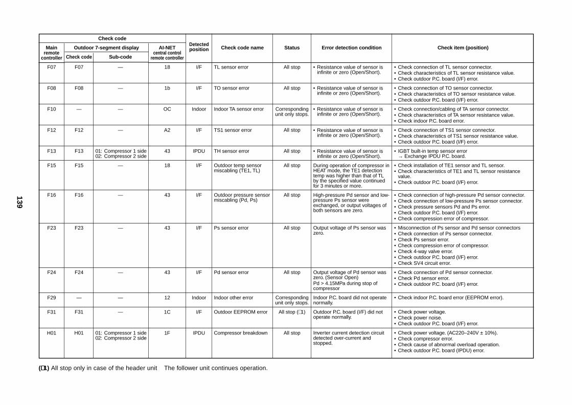
Check code
Mainremote
controller
F07
F08
F10
F12
F13
F15
F16
F23
F24
F29
F31
H01
Outdoor 7-segment display
Check code Sub-code
F07 —
F08 —
— —
F12 —
F13 01: Compressor 1 side02: Compressor 2 side
F15 —
F16 —
F23 —
F24 —
— —
F31 —
H01 01: Compressor 1 side02: Compressor 2 side
AI-NETcentral control
remote controller
18
1b
OC
A2
43
18
43
43
43
12
1C
1F
Detectedposition
I/F
I/F
Indoor
I/F
IPDU
I/F
I/F
I/F
I/F
Indoor
I/F
IPDU
Check code name
TL sensor error
TO sensor error
Indoor TA sensor error
TS1 sensor error
TH sensor error
Outdoor temp sensormiscabling (TE1, TL)
Outdoor pressure sensormiscabling (Pd, Ps)
Ps sensor error
Pd sensor error
Indoor other error
Outdoor EEPROM error
Compressor breakdown
Status
All stop
All stop
Correspondingunit only stops.
All stop
All stop
All stop
All stop
All stop
All stop
Correspondingunit only stops.
All stop (∗ 1)
All stop
Error detection condition
• Resistance value of sensor isinfinite or zero (Open/Short).
• Resistance value of sensor isinfinite or zero (Open/Short).
• Resistance value of sensor isinfinite or zero (Open/Short).
• Resistance value of sensor isinfinite or zero (Open/Short).
• Resistance value of sensor isinfinite or zero (Open/Short).
During operation of compressor inHEAT mode, the TE1 detectiontemp was higher than that of TLby the specified value continuedfor 3 minutes or more.
High-pressure Pd sensor and low-pressure Ps sensor wereexchanged, or output voltages ofboth sensors are zero.
Output voltage of Ps sensor waszero.
Output voltage of Pd sensor waszero. (Sensor Open)Pd > 4.15MPa during stop ofcompressor
Indoor P.C. board did not operatenormally.
Outdoor P.C. board (I/F) did notoperate normally.
Inverter current detection circuitdetected over-current andstopped.
Check item (position)
• Check connection of TL sensor connector.• Check characteristics of TL sensor resistance value.• Check outdoor P.C. board (I/F) error.
• Check connection of TO sensor connector.• Check characteristics of TO sensor resistance value.• Check outdoor P.C. board (I/F) error.
• Check connection/cabling of TA sensor connector.• Check characteristics of TA sensor resistance value.• Check indoor P.C. board error.
• Check connection of TS1 sensor connector.• Check characteristics of TS1 sensor resistance value.• Check outdoor P.C. board (I/F) error.
• IGBT built-in temp sensor error→ Exchange IPDU P.C. board.
• Check installation of TE1 sensor and TL sensor.• Check characteristics of TE1 and TL sensor resistance
value.• Check outdoor P.C. board (I/F) error.
• Check connection of high-pressure Pd sensor connector.• Check connection of low-pressure Ps sensor connector.• Check pressure sensors Pd and Ps error.• Check outdoor P.C. board (I/F) error.• Check compression error of compressor.
• Misconnection of Ps sensor and Pd sensor connectors• Check connection of Ps sensor connector.• Check Ps sensor error.• Check compression error of compressor.• Check 4-way valve error.• Check outdoor P.C. board (I/F) error.• Check SV4 circuit error.
• Check connection of Pd sensor connector.• Check Pd sensor error.• Check outdoor P.C. board (I/F) error.
• Check indoor P.C. board error (EEPROM error).
• Check power voltage.• Check power noise.• Check outdoor P.C. board (I/F) error.
• Check power voltage. (AC220–240V ± 10%).• Check compressor error.• Check cause of abnormal overload operation.• Check outdoor P.C. board (IPDU) error.
(∗∗∗∗∗ 1) All stop only in case of the header unit The follower unit continues operation.
140
Check code
Mainremote
controller
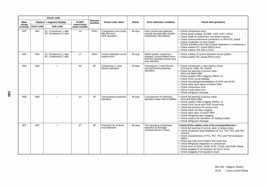
H02
H03
H04
H06
H07
Outdoor 7-segment display
Check code Sub-code
H02 01: Compressor 1 side02: Compressor 2 side
H03 01: Compressor 1 side02: Compressor 2 side
H04 —
H06 —
H07 —
AI-NETcentral control
remote controller
1d
17
44
20
d7
Detectedposition
IPDU
IPDU
I/F
I/F
I/F
Check code name
Compressor error (lock)MG-SW errorOCR operation
Current detection circuitsystem error
Compressor 1 casethermo operation
Low-pressure protectiveoperation
Protection for oil leveldrop detection
Status
All stop
All stop
All stop
All stop
All stop
Error detection condition
Over-current was detectedseveral seconds after headercompressor had started.
While header compressorstopped, current flowed morethan the specified current andwas detected.
Compressor 1 case thermo-stat performed protectiveoperation.
Low-pressure Ps detectedoperation lower than 0.02MPa.
The operating compressordetected oil shortagecontinuously for 2 hours.
Check item (position)
• Check compressor error.• Check power voltage. (AC380 –10%, 415V +10%).• Check cable of compressor and phase-missing.• Check connector/terminal connection on IPDU P.C. board.• Check conduction of case heater.
(Check activation error due to liquid stagnation in compressor.)• Check outdoor P.C. board (IPDU) error.• Check outdoor MG-SW or OCR.
• Check cabling of current detection circuit system.• Check outdoor P.C. board (IPDU) error.
• Check compressor 1 case thermo circuit.(Connector, cable, P.C. board)
• Check full opening of service valve.(Gas and liquid side)
• Check outdoor PMV clogging. (PMV1, 2)• Check SV41 circuit leakage.• Check miscabling/misinstallation of SV41 and SV42.• Check valve open status of indoor PMV.• Check compressor error.• Check 4-way valve error.• Check refrigerant shortage.
• Check full opening of service valve.(Gas and liquid side)
• Check outdoor PMV clogging. (PMV1, 2)• Check SV41 circuit and SV42 circuit error.• Check low-pressure Ps sensor error.• Check indoor air filter clogging.• Check valve open of indoor PMV.• Check refrigerant pipe clogging.• Check outdoor fan operation. (In heating mode)• Check refrigerant shortage.
<Check all the outdoor units in the corresponding line.>• Check full opening of service valve of balance pipe.• Check connection and installation of TK1, TK2, TK3, and TK4
sensors.• Check characteristics of TK1, TK2, TK3, and TK4 resistance
values.• Check gas leak and oil leak in the same line.• Check refrigerant stagnation in compressor.• Check error of SV3A, SV3B, SV3C, SV3D, and SV3E valves.• Check clogging of oil separator oil return circuit.• Check clogging of oil-equation circuit.
MG-SW : Magnet Switch
OCR : Over-current Relay
141
Check code
Mainremote
controller
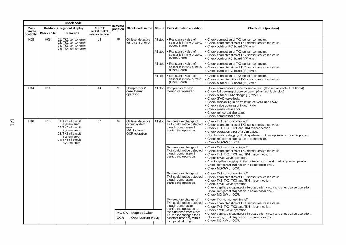
H08
H14
H16
Outdoor 7-segment display
Check code Sub-code
H08 01: TK1 sensor error02: TK2 sensor error03: TK3 sensor error04: TK4 sensor error
H14 —
H16 01: TK1 oil circuitsystem error
02: TK2 oil circuitsystem error
03: TK3 oil circuitsystem error
04: TK4 oil circuitsystem error
AI-NETcentral control
remote controller
d4
44
d7
Detectedposition
I/F
I/F
I/F
Check code name
Oil level detectivetemp sensor error
Compressor 2case thermooperation
Oil level detectivecircuit systemerrorMG-SW errorOCR operation
Status
All stop
All stop
All stop
All stop
All stop
All stop
Error detection condition
• Resistance value ofsensor is infinite or zero.(Open/Short)
• Resistance value ofsensor is infinite or zero.(Open/Short)
• Resistance value ofsensor is infinite or zero.(Open/Short)
• Resistance value ofsensor is infinite or zero.(Open/Short)
Compressor 2 casethermostat operated.
Temperature change ofTK1 could not be detectedthough compressor 1started the operation.
Temperature change ofTK2 could not be detectedthough compressor 2started the operation.
Temperature change ofTK3 could not be detectedthough compressorstarted the operation.
Temperature change ofTK4 could not be detectedthough compressorstarted the operation, orthe difference from otherTK sensor changed for aconstant time only withinthe specified range.
Check item (position)
• Check connection of TK1 sensor connector.• Check characteristics of TK1 sensor resistance value.• Check outdoor P.C. board (I/F) error.
• Check connection of TK2 sensor connector.• Check characteristics of TK2 sensor resistance value.• Check outdoor P.C. board (I/F) error.
• Check connection of TK3 sensor connector.• Check characteristics of TK3 sensor resistance value.• Check outdoor P.C. board (I/F) error.
• Check connection of TK4 sensor connector.• Check characteristics of TK4 sensor resistance value.• Check outdoor P.C. board (I/F) error.
• Check compressor 2 case thermo circuit. (Connector, cable, P.C. board)• Check full opening of service valve. (Gas and liquid side)• Check outdoor PMV clogging. (PMV1, 2)• Check SV42 valve leak.• Check miscabling/misinstallation of SV41 and SV42.• Check valve opening of indoor PMV.• Check 4-way valve error.• Check refrigerant shortage.• Check compressor error.
• Check TK1 sensor coming-off.• Check characteristics of TK1 sensor resistance value.• Check TK1, TK2, TK3, and TK4 misconnection.• Check operation error of SV3E valve.• Check capillary clogging of oil-equation circuit and operation error of stop valve.• Check refrigerant stagnation in compressor.• Check MG-SW or OCR.
• Check TK2 sensor coming-off.• Check characteristics of TK2 sensor resistance value.• Check TK1, TK2, TK3, and TK4 misconnection.• Check SV3E valve operation.• Check capillary clogging of oil equalization circuit and check stop valve operation.• Check refrigerant stagnation in compressor shell.• Check MG-SW or OCR.
• Check TK3 sensor coming-off.• Check characteristics of TK3 sensor resistance value.• Check TK1, TK2, TK3, and TK4 misconnection.• Check SV3E valve operation.• Check capillary clogging of oil-equalization circuit and check valve operation.• Check refrigerant stagnation in compressor shell.• Check MG-SW or OCR.
• Check TK4 sensor coming-off.• Check characteristics of TK4 sensor resistance value.• Check TK1, TK2, TK3, and TK4 misconnection.• Check SV3E valve operation.• Check capillary clogging of oil-equalization circuit and check valve operation.• Check refrigerant stagnation in compressor shell.• Check MG-SW or OCR.
MG-SW : Magnet Switch
OCR : Over-current Relay
142
Check code
Mainremote
controller
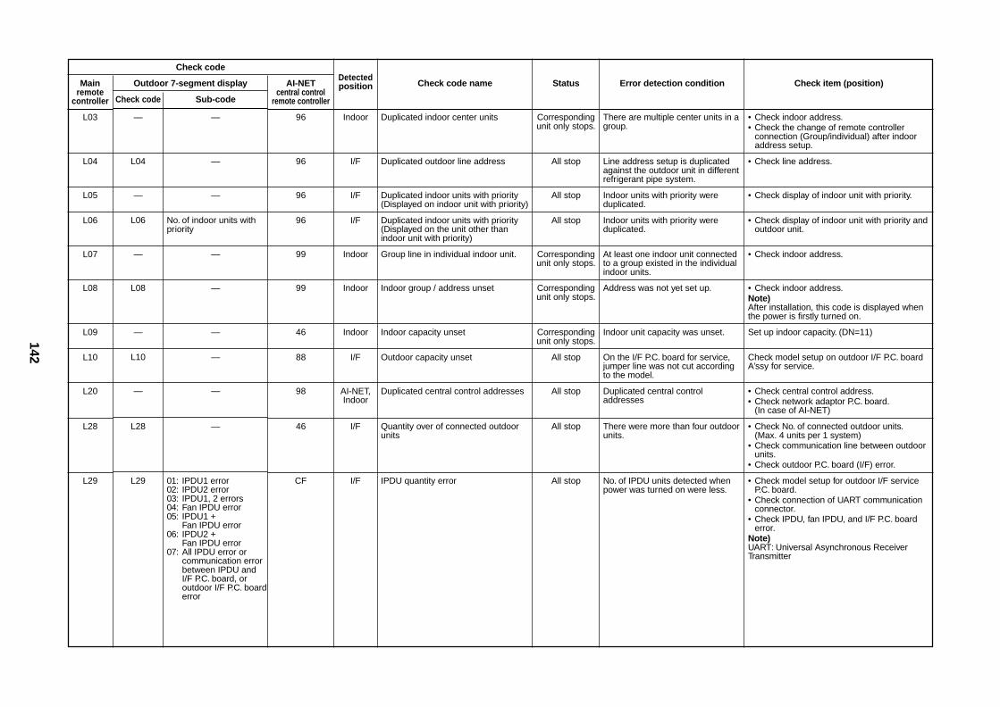
L03
L04
L05
L06
L07
L08
L09
L10
L20
L28
L29
Outdoor 7-segment display
Check code Sub-code
— —
L04 —
— —
L06 No. of indoor units withpriority
— —
L08 —
— —
L10 —
— —
L28 —
L29 01: IPDU1 error02: IPDU2 error03: IPDU1, 2 errors04: Fan IPDU error05: IPDU1 +
Fan IPDU error06: IPDU2 +
Fan IPDU error07: All IPDU error or
communication errorbetween IPDU andI/F P.C. board, oroutdoor I/F P.C. boarderror
AI-NETcentral control
remote controller
96
96
96
96
99
99
46
88
98
46
CF
Detectedposition
Indoor
I/F
I/F
I/F
Indoor
Indoor
Indoor
I/F
AI-NET,Indoor
I/F
I/F
Check code name
Duplicated indoor center units
Duplicated outdoor line address
Duplicated indoor units with priority(Displayed on indoor unit with priority)
Duplicated indoor units with priority(Displayed on the unit other thanindoor unit with priority)
Group line in individual indoor unit.
Indoor group / address unset
Indoor capacity unset
Outdoor capacity unset
Duplicated central control addresses
Quantity over of connected outdoorunits
IPDU quantity error
Status
Correspondingunit only stops.
All stop
All stop
All stop
Correspondingunit only stops.
Correspondingunit only stops.
Correspondingunit only stops.
All stop
All stop
All stop
All stop
Error detection condition
There are multiple center units in agroup.
Line address setup is duplicatedagainst the outdoor unit in differentrefrigerant pipe system.
Indoor units with priority wereduplicated.
Indoor units with priority wereduplicated.
At least one indoor unit connectedto a group existed in the individualindoor units.
Address was not yet set up.
Indoor unit capacity was unset.
On the I/F P.C. board for service,jumper line was not cut accordingto the model.
Duplicated central controladdresses
There were more than four outdoorunits.
No. of IPDU units detected whenpower was turned on were less.
Check item (position)
• Check indoor address.• Check the change of remote controller
connection (Group/individual) after indooraddress setup.
• Check line address.
• Check display of indoor unit with priority.
• Check display of indoor unit with priority andoutdoor unit.
• Check indoor address.
• Check indoor address.Note)After installation, this code is displayed whenthe power is firstly turned on.
Set up indoor capacity. (DN=11)
Check model setup on outdoor I/F P.C. boardA’ssy for service.
• Check central control address.• Check network adaptor P.C. board.
(In case of AI-NET)
• Check No. of connected outdoor units.(Max. 4 units per 1 system)
• Check communication line between outdoorunits.
• Check outdoor P.C. board (I/F) error.
• Check model setup for outdoor I/F serviceP.C. board.
• Check connection of UART communicationconnector.
• Check IPDU, fan IPDU, and I/F P.C. boarderror.
Note)UART: Universal Asynchronous ReceiverTransmitter
143
Check code
Mainremote
controller
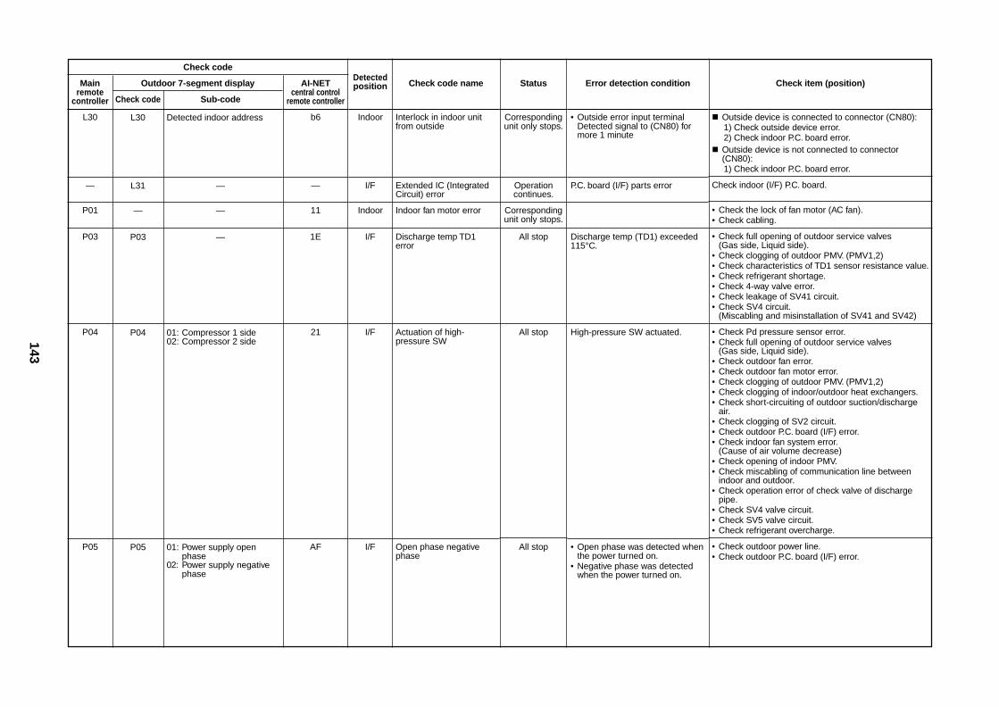
L30
—
P01
P03
P04
P05
Outdoor 7-segment display
Check code Sub-code
L30 Detected indoor address
L31 —
— —
P03 —
P04 01: Compressor 1 side02: Compressor 2 side
P05 01: Power supply openphase
02: Power supply negativephase
AI-NETcentral control
remote controller
b6
—
11
1E
21
AF
Detectedposition
Indoor
I/F
Indoor
I/F
I/F
I/F
Check code name
Interlock in indoor unitfrom outside
Extended IC (IntegratedCircuit) error
Indoor fan motor error
Discharge temp TD1error
Actuation of high-pressure SW
Open phase negativephase
Status
Correspondingunit only stops.
Operationcontinues.
Correspondingunit only stops.
All stop
All stop
All stop
Error detection condition
• Outside error input terminalDetected signal to (CN80) formore 1 minute
P.C. board (I/F) parts error
Discharge temp (TD1) exceeded115°C.
High-pressure SW actuated.
• Open phase was detected whenthe power turned on.
• Negative phase was detectedwhen the power turned on.
Check item (position)
Outside device is connected to connector (CN80):1) Check outside device error.2) Check indoor P.C. board error.
Outside device is not connected to connector(CN80):1) Check indoor P.C. board error.
Check indoor (I/F) P.C. board.
• Check the lock of fan motor (AC fan).• Check cabling.
• Check full opening of outdoor service valves(Gas side, Liquid side).
• Check clogging of outdoor PMV. (PMV1,2)• Check characteristics of TD1 sensor resistance value.• Check refrigerant shortage.• Check 4-way valve error.• Check leakage of SV41 circuit.• Check SV4 circuit.
(Miscabling and misinstallation of SV41 and SV42)
• Check Pd pressure sensor error.• Check full opening of outdoor service valves
(Gas side, Liquid side).• Check outdoor fan error.• Check outdoor fan motor error.• Check clogging of outdoor PMV. (PMV1,2)• Check clogging of indoor/outdoor heat exchangers.• Check short-circuiting of outdoor suction/discharge
air.• Check clogging of SV2 circuit.• Check outdoor P.C. board (I/F) error.• Check indoor fan system error.
(Cause of air volume decrease)• Check opening of indoor PMV.• Check miscabling of communication line between
indoor and outdoor.• Check operation error of check valve of discharge
pipe.• Check SV4 valve circuit.• Check SV5 valve circuit.• Check refrigerant overcharge.
• Check outdoor power line.• Check outdoor P.C. board (I/F) error.
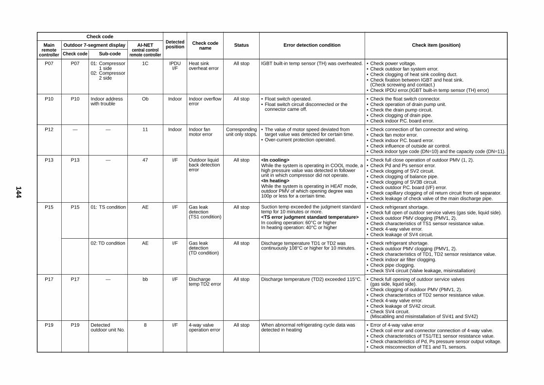
144
Check code
Mainremote
controller
P07
P10
P12
P13
P15
P17
P19
Outdoor 7-segment display
Check code Sub-code
P07 01: Compressor1 side
02: Compressor2 side
P10 Indoor addresswith trouble
— —
P13 —
P15 01: TS condition
02: TD condition
P17 —
P19 Detectedoutdoor unit No.
AI-NETcentral control
remote controller
1C
Ob
11
47
AE
AE
bb
8
Detectedposition
IPDUI/F
Indoor
Indoor
I/F
I/F
I/F
I/F
I/F
Check codename
Heat sinkoverheat error
Indoor overflowerror
Indoor fanmotor error
Outdoor liquidback detectionerror
Gas leakdetection(TS1 condition)
Gas leakdetection(TD condition)
Dischargetemp TD2 error
4-way valveoperation error
Status
All stop
All stop
Correspondingunit only stops.
All stop
All stop
All stop
All stop
All stop
Error detection condition
IGBT built-in temp sensor (TH) was overheated.
• Float switch operated.• Float switch circuit disconnected or the
connector came off.
• The value of motor speed deviated fromtarget value was detected for certain time.
• Over-current protection operated.
<In cooling>While the system is operating in COOL mode, ahigh pressure value was detected in followerunit in which compressor did not operate.<In heating>While the system is operating in HEAT mode,outdoor PMV of which opening degree was100p or less for a certain time.
Suction temp exceeded the judgment standardtemp for 10 minutes or more.<TS error judgment standard temperature>In cooling operation: 60°C or higherIn heating operation: 40°C or higher
Discharge temperature TD1 or TD2 wascontinuously 108°C or higher for 10 minutes.
Discharge temperature (TD2) exceeded 115°C.
When abnormal refrigerating cycle data wasdetected in heating
Check item (position)
• Check power voltage.• Check outdoor fan system error.• Check clogging of heat sink cooling duct.• Check fixation between IGBT and heat sink.
(Check screwing and contact.)• Check IPDU error.(IGBT built-in temp sensor (TH) error)
• Check the float switch connector.• Check operation of drain pump unit.• Check the drain pump circuit.• Check clogging of drain pipe.• Check indoor P.C. board error.
• Check connection of fan connector and wiring.• Check fan motor error.• Check indoor P.C. board error.• Check influence of outside air control.• Check indoor type code (DN=10) and the capacity code (DN=11).
• Check full close operation of outdoor PMV (1, 2).• Check Pd and Ps sensor error.• Check clogging of SV2 circuit.• Check clogging of balance pipe.• Check clogging of SV3B circuit.• Check outdoor P.C. board (I/F) error.• Check capillary clogging of oil return circuit from oil separator.• Check leakage of check valve of the main discharge pipe.
• Check refrigerant shortage.• Check full open of outdoor service valves (gas side, liquid side).• Check outdoor PMV clogging (PMV1, 2).• Check characteristics of TS1 sensor resistance value.• Check 4-way valve error.• Check leakage of SV4 circuit.
• Check refrigerant shortage.• Check outdoor PMV clogging (PMV1, 2).• Check characteristics of TD1, TD2 sensor resistance value.• Check indoor air filter clogging.• Check pipe clogging.• Check SV4 circuit (Valve leakage, misinstallation)
• Check full opening of outdoor service valves(gas side, liquid side).
• Check clogging of outdoor PMV (PMV1, 2).• Check characteristics of TD2 sensor resistance value.• Check 4-way valve error.• Check leakage of SV42 circuit.• Check SV4 circuit.
(Miscabling and misinstallation of SV41 and SV42)
• Error of 4-way valve error• Check coil error and connector connection of 4-way valve.• Check characteristics of TS1/TE1 sensor resistance value.• Check characteristics of Pd, Ps pressure sensor output voltage.• Check misconnection of TE1 and TL sensors.
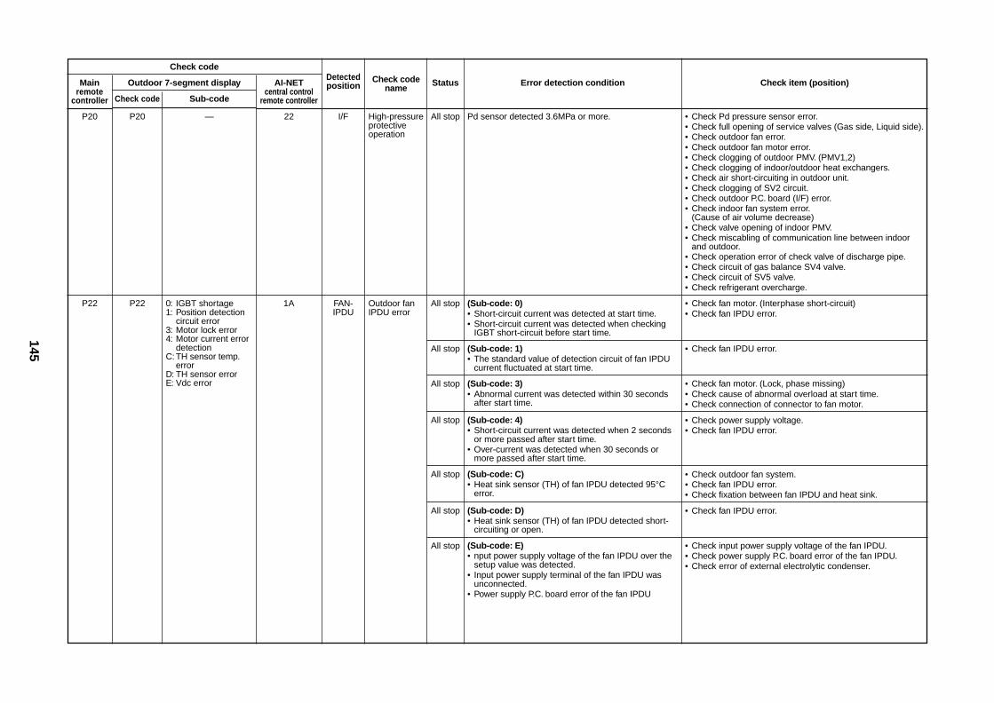
145
Check code
Mainremote
controller
P20
P22
Outdoor 7-segment display
Check code Sub-code
P20 —
P22 0: IGBT shortage1: Position detection
circuit error3: Motor lock error4: Motor current error
detectionC: TH sensor temp.
errorD: TH sensor errorE: Vdc error
AI-NETcentral control
remote controller
22
1A
Detectedposition
I/F
FAN-IPDU
Check codename
High-pressureprotectiveoperation
Outdoor fanIPDU error
Status
All stop
All stop
All stop
All stop
All stop
All stop
All stop
All stop
Error detection condition
Pd sensor detected 3.6MPa or more.
(Sub-code: 0)• Short-circuit current was detected at start time.• Short-circuit current was detected when checking
IGBT short-circuit before start time.
(Sub-code: 1)• The standard value of detection circuit of fan IPDU
current fluctuated at start time.
(Sub-code: 3)• Abnormal current was detected within 30 seconds
after start time.
(Sub-code: 4)• Short-circuit current was detected when 2 seconds
or more passed after start time.• Over-current was detected when 30 seconds or
more passed after start time.
(Sub-code: C)• Heat sink sensor (TH) of fan IPDU detected 95°C
error.
(Sub-code: D)• Heat sink sensor (TH) of fan IPDU detected short-
circuiting or open.
(Sub-code: E)• nput power supply voltage of the fan IPDU over the
setup value was detected.• Input power supply terminal of the fan IPDU was
unconnected.• Power supply P.C. board error of the fan IPDU
Check item (position)
• Check Pd pressure sensor error.• Check full opening of service valves (Gas side, Liquid side).• Check outdoor fan error.• Check outdoor fan motor error.• Check clogging of outdoor PMV. (PMV1,2)• Check clogging of indoor/outdoor heat exchangers.• Check air short-circuiting in outdoor unit.• Check clogging of SV2 circuit.• Check outdoor P.C. board (I/F) error.• Check indoor fan system error.
(Cause of air volume decrease)• Check valve opening of indoor PMV.• Check miscabling of communication line between indoor
and outdoor.• Check operation error of check valve of discharge pipe.• Check circuit of gas balance SV4 valve.• Check circuit of SV5 valve.• Check refrigerant overcharge.
• Check fan motor. (Interphase short-circuit)• Check fan IPDU error.
• Check fan IPDU error.
• Check fan motor. (Lock, phase missing)• Check cause of abnormal overload at start time.• Check connection of connector to fan motor.
• Check power supply voltage.• Check fan IPDU error.
• Check outdoor fan system.• Check fan IPDU error.• Check fixation between fan IPDU and heat sink.
• Check fan IPDU error.
• Check input power supply voltage of the fan IPDU.• Check power supply P.C. board error of the fan IPDU.• Check error of external electrolytic condenser.
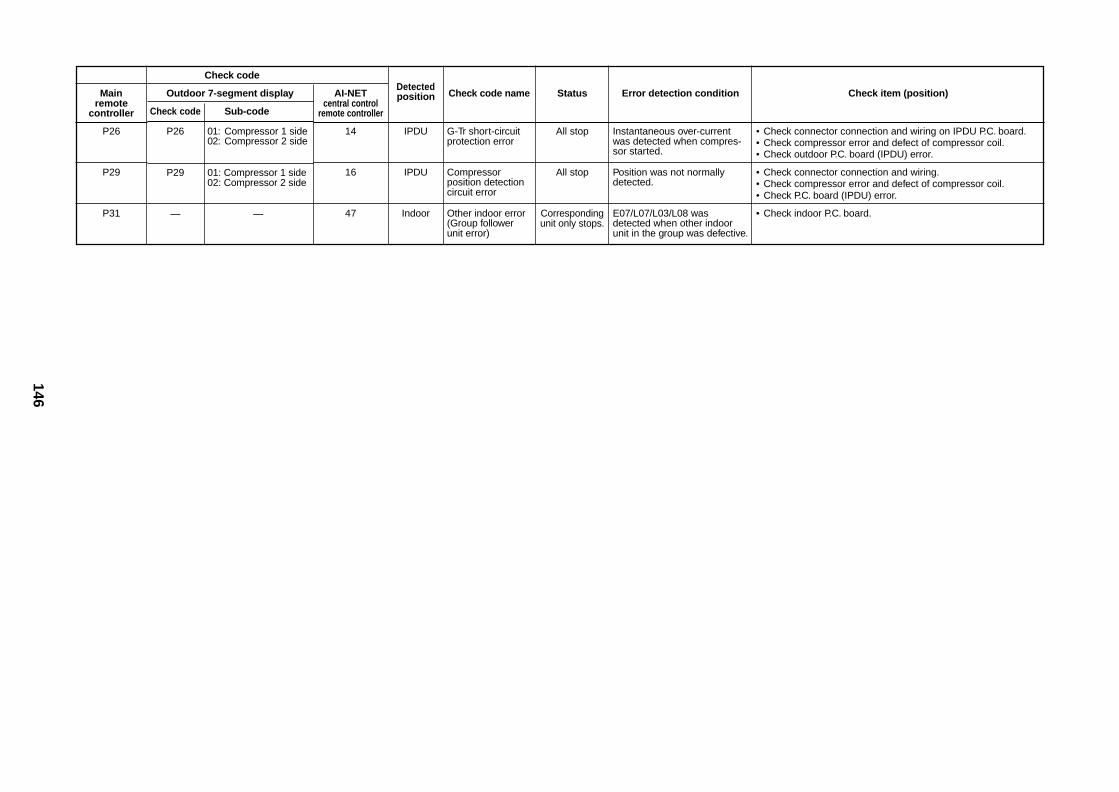
146
Check code
Mainremote
controller
P26
P29
P31
Outdoor 7-segment display
Check code Sub-code
P26 01: Compressor 1 side02: Compressor 2 side
P29 01: Compressor 1 side02: Compressor 2 side
— —
AI-NETcentral control
remote controller
14
16
47
Detectedposition
IPDU
IPDU
Indoor
Check code name
G-Tr short-circuitprotection error
Compressorposition detectioncircuit error
Other indoor error(Group followerunit error)
Status
All stop
All stop
Correspondingunit only stops.
Error detection condition
Instantaneous over-currentwas detected when compres-sor started.
Position was not normallydetected.
E07/L07/L03/L08 wasdetected when other indoorunit in the group was defective.
Check item (position)
• Check connector connection and wiring on IPDU P.C. board.• Check compressor error and defect of compressor coil.• Check outdoor P.C. board (IPDU) error.
• Check connector connection and wiring.• Check compressor error and defect of compressor coil.• Check P.C. board (IPDU) error.
• Check indoor P.C. board.
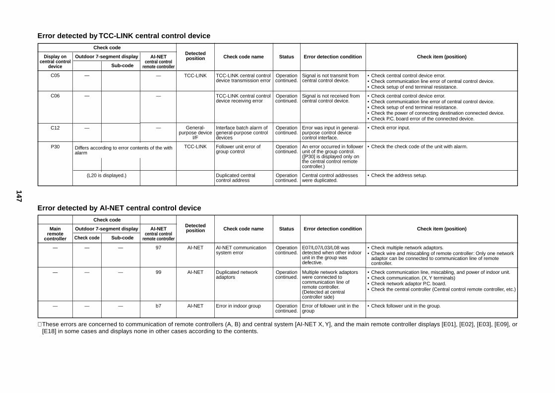
147
Error detected by TCC-LINK central control device
Check code
Display oncentral control
device
C05
C06
C12
P30
Outdoor 7-segment display
Sub-code
—
—
—
(L20 is displayed.)
AI-NETcentral control
remote controller
—
—
—
Detectedposition
TCC-LINK
General-purpose device
I/F
TCC-LINK
Check code name
TCC-LINK central controldevice transmission error
TCC-LINK central controldevice receiving error
Interface batch alarm ofgeneral-purpose controldevices
Follower unit error ofgroup control
Duplicated centralcontrol address
Status
Operationcontinued.
Operationcontinued.
Operationcontinued.
Operationcontinued.
Operationcontinued.
Error detection condition
Signal is not transmit fromcentral control device.
Signal is not received fromcentral control device.
Error was input in general-purpose control devicecontrol interface.
An error occurred in followerunit of the group control.([P30] is displayed only onthe central control remotecontroller.)
Central control addresseswere duplicated.
Check item (position)
• Check central control device error.• Check communication line error of central control device.• Check setup of end terminal resistance.
• Check central control device error.• Check communication line error of central control device.• Check setup of end terminal resistance.• Check the power of connecting destination connected device.• Check P.C. board error of the connected device.
• Check error input.
• Check the check code of the unit with alarm.
• Check the address setup.
Differs according to error contents of the withalarm
Error detected by AI-NET central control device
Check code
Mainremote
controller
—
—
—
Outdoor 7-segment display
Check code Sub-code
— —
— —
— —
AI-NETcentral control
remote controller
97
99
b7
Detectedposition
AI-NET
AI-NET
AI-NET
Check code name
AI-NET communicationsystem error
Duplicated networkadaptors
Error in indoor group
Status
Operationcontinued.
Operationcontinued.
Operationcontinued.
Error detection condition
E07/L07/L03/L08 wasdetected when other indoorunit in the group wasdefective.
Multiple network adaptorswere connected tocommunication line ofremote controller.(Detected at centralcontroller side)
Error of follower unit in thegroup
Check item (position)
• Check multiple network adaptors.• Check wire and miscabling of remote controller: Only one network
adaptor can be connected to communication line of remotecontroller.
• Check communication line, miscabling, and power of indoor unit.• Check communication. (X, Y terminals)• Check network adaptor P.C. board.• Check the central controller (Central control remote controller, etc.)
• Check follower unit in the group.
∗ These errors are concerned to communication of remote controllers (A, B) and central system [AI-NET X, Y], and the main remote controller displays [E01], [E02], [E03], [E09], or[E18] in some cases and displays none in other cases according to the contents.