Embed Size (px)
DESCRIPTION
wdwd
Citation preview

EDSG18-936
- Cooling Only -
E-Series

EDSG18-936
Part 1 Features ............................................................................11. Features ..................................................................................................2
1.1 Features ...................................................................................................21.2 Selection Procedure .................................................................................61.3 Control System.........................................................................................8
Part 2 Multi-Split System Room Air ConditionersSUPER MULTI PLUS E-Series Cooling Only ....................13
1. Power Supply ........................................................................................152. Functions...............................................................................................163. Specifications ........................................................................................20
3.1 Outdoor Units .........................................................................................203.2 BP Unit ...................................................................................................213.3 Combination Capacity Index ..................................................................223.4 Indoor Units ............................................................................................25
4. Dimensions ...........................................................................................324.1 Outdoor Units .........................................................................................324.2 BP Units .................................................................................................334.3 Indoor Units ............................................................................................34
5. Wiring Diagrams....................................................................................455.1 Outdoor Units .........................................................................................455.2 BP Units .................................................................................................465.3 Indoor Units ............................................................................................47
6. Piping Diagrams....................................................................................526.1 Outdoor Units .........................................................................................526.2 BP Units .................................................................................................536.3 Indoor Units ............................................................................................54
7. Capacity Tables ....................................................................................577.1 Total Capacity ........................................................................................577.2 Capacity Correction Factor by the Length of Refrigerant Piping ............63
8. Operation Limit......................................................................................659. Fan Characteristics ...............................................................................6610.Sound Level ..........................................................................................69
10.1 Measuring Location ................................................................................6910.2 Octave Band Level .................................................................................70
11.Electric Characteristics..........................................................................73
Part 3 Installation Manual .........................................................751. Outdoor Units ........................................................................................76
1.1 Installation ..............................................................................................761.2 Service Precautions ...............................................................................94
2. BP Units ................................................................................................983. Indoor Units.........................................................................................110
3.1 Safety Precautions ...............................................................................1103.2 Wall Mounted Type FTKS25/35D.........................................................1113.3 Wall Mounted Type FTKS50/60/71F ....................................................1193.4 Wall Mounted Type FTKS50B..............................................................1263.5 Duct Connected Type FDKS25/35CA..................................................134
SUPER MULTI PLUS E-Series i
EDSG18-936
3.6 Duct Connected Type FDKS50/60C, FDKS25/35EA ...........................1443.7 Ceiling Mounted Cassette Type FFQ25/35/50/60B..............................1543.8 Ceiling Mounted Cassette Type FCQ35/50/60/71B .............................1763.9 Ceiling Mounted Built-in Type FBQ60/71B...........................................199
Part 4 Operation Manual ..........................................................2191. Operations...........................................................................................220
1.1 RMKS112/140/160E Series .................................................................2201.2 FTKS, FDKS Series .............................................................................2211.3 FFQ25/35/50/60B Series......................................................................2751.4 FCQ35/50/60/71B Series .....................................................................2881.5 FBQ60/71B Series ...............................................................................299
Part 5 Options ..........................................................................3091. Option List ...........................................................................................310
1.1 Outdoor Units .......................................................................................3101.2 BP Units ...............................................................................................3101.3 Indoor Units ..........................................................................................310
2. Options for Outdoor & BP Units ..........................................................3142.1 Options for Outdoor Units.....................................................................3142.2 Options for BP Units.............................................................................315
3. Options for Indoor Units ......................................................................3183.1 Duct Connected Type...........................................................................3183.2 Ceiling Mounted Cassette Type (600×600)..........................................3193.3 Ceiling Mounted Cassette Type (950×950)..........................................3293.4 Ceiling Mounted Built-in Type ..............................................................345
4. Control Devices...................................................................................3554.1 <DCS302CA61> Central Remote Controller .......................................3554.2 <DCS301BA61> Unified ON/OFF Controller .......................................3874.3 <DST301BA61> Schedule Timer .........................................................3954.4 Combination of <DCS302CA61 / DCS301BA61 / DST301BA61>
Combinations of Optional Controllers for Centralized Control..............4144.5 <KRP928B2S> Interface Adaptor for DIII-NET
(Residential Air Conditioner) ................................................................4174.6 <DTA112BA51> Interface Adaptor for DIII-NET (SkyAir).....................4194.7 <KRC72> Centralized Control Board-up to 5 Rooms...........................4214.8 <KRP413A1S> Wiring Adaptor for Timer Clock / Remote Controller...4234.9 <KRP4AA51/53> Wiring Adaptor for Electrical Appendices.................4274.10 <KRP1BA54/57> Adaptor for Wiring ....................................................4324.11 <KRP1BA101> Installation Box for Adaptor PCB ................................4334.12 <KRCS01-1B> Remote Sensor............................................................4354.13 <BRC1C61> Wired Remote Controller for SkyAir................................4384.14 <BRC7C613W> Wireless Remote Controller.......................................4454.15 <BRC7E531W> Wireless Remote Controller.......................................450
ii SUPER MULTI PLUS E-Series

EDSG18-936
Features 1
1Part 1Features
1. Features ..................................................................................................21.1 Features ...................................................................................................21.2 Selection Procedure .................................................................................61.3 Control System.........................................................................................8

Features EDSG18-936
1. Features1.1 Features
More Variation of Indoor UnitsMore Variation of Indoor UnitsL.S.P. Duct Slim & Compact TypeL.S.P. Duct Slim & Compact Type
Energy SavingEnergy SavingDeveloped DAIKIN original Developed DAIKIN original new scroll compressor
Quiet OperationQuiet OperationNight Quiet ModeNight Quiet Mode
Easy InstallationEasy InstallationAutomatic Test OperationAutomatic Test OperationEasy Wiring WorkingEasy Wiring Working
Easy MaintenanceEasy MaintenanceOperation Data Memory Function Operation Data Memory Functionbefore failurebefore failure
Features
RMKS112E (4HP)RMKS140E (5HP)RMKS160E (6HP)
new scroll compressor
06RAG09-2
Indoor Units
Mo/C Mo/CMo/CMo/C
FDKS-CVMBFDKS-CVMB
FTKS-BVMAFTKS-BVMA
Model NameModel Name
FCQ-BVEFCQ-BVE
FBQ-BV1FBQ-BV1
FDKS-CAVMBFDKS-CAVMB
FDKS-EAVMBFDKS-EAVMB
FTKS-DVMFTKS-DVM
Ceiling Mounted CassetteCeiling Mounted Cassette(950x950 Multi Flow)(950x950 Multi Flow)
FFQ-BV1B9Ceiling Mounted CassetteCeiling Mounted Cassette(600x600 Multi Flow)
M.S.P. Ceiling Mounted Built-in
71716060505035352525
L.S.P. Duct (Slim)
L.S.P. Duct (Slim Compact)
Wall MountedWall Mounted
TypeType
Added slim & compact duct type which is suitable for a small room. Meet more variation of needs!
Cooling OnlyCooling Only : New Model Mo/C: Mo/C model : Continued Model : Invalidated Model
L.S.P. Duct (Slim Compact)
L.S.P. Duct (Slim)
M.S.P. Ceiling Mounted Built-in
FTKS-FVMFTKS-FVM
(600x600 Multi Flow)FFQ-BV1B9
06RAG09-14
Wall Mounted
< FTKS50B >
< FTKS50-71F >
Duct Connected
< FTKS25/35D >
Cassette
Built-in
950x950< FCQ35-71B >
600x600< FFQ25-60B >
< FBQ60/71B >Slim & Compact Type
< FDKS25/35EA >
Slim type (25-60 class)< FDKS25/35CA >< FDKS50/60C >
External Appearance
(25/35 class)
06RAG09-20
2 Features

EDSG18-936 Features
1
High Thrustmechanism
Highprecisionscrolling
DifferentialPressure Pump
Hydro DynamicBearing
Rotor
Stator
High Efficiency G Type Compressor
High-pressurepushing power
Compressedgas load
Housing
FixedScroll
CrankShaft
MovingScroll
Reduction ofSliding Loss
High PressureOil
High Pressure
Low Pressure
Pushing backPower of HighPressure Oil
Thrust Slide Part
High Thrust mechanism
DC motorof highefficiencyand lowvibration
The efficient scroll G type compressor realized further energy savingHigh Thrust mechanism realized a reduction of friction loss and leaks of refrigerant and high efficiency.- Improvement in scroll performance by high precision processing technology (improvement in thedegree of outline of VOLUTE)
New Scroll Compressor
06RAG09-23
(dBA)
Night Quiet Mode
3 steps of setting are possible (Button setting of an outdoor un3 steps of setting are possible (Button setting of an outdoor unit PC Board). it PC Board).
Note: This function is available in setting at site.The relationship of outdoor temperature (load) and time shown in the graph is just an example.
41STEP3
44STEP2
47STEP1
41STEP3
44STEP2
47STEP1
Night Quiet ModeNight Quiet Mode
Night Quiet Mode StartsNight Quiet Mode Starts Night Quiet Mode EndsNight Quiet Mode Ends
06RAG09-24
Automatic Test Operation
Check of wiring, stop valves, sensors and refrigerant volumeautomatically.
Just press the “test operation” button afterrefrigerant charging completes. The check of wiring,stop valves, sensors and refrigerant volume isperformed. The operation stops automaticallywhen the check is completed.
Simply press thetest operationbutton!
Test OperationTest Operation
06RAG09-25
Features 3

Features EDSG18-936
Current Model
Easy Wiring WorkImproved the shape of PCB. Divided the operating part and theterminal plate for easy wiring work.
Transmission wiring
Operating part
Connection (to BP Unit)
06RAG09-26
When a malfunction occur, operating data for the 3 minutes preceding thebreakdown is stored in memory automatically. This function speeds up theprocess of identifying and correcting the cause of the problem.
Memory Function of the Operation Data before Failure
Normal OperationMalfunctionMalfunction
Automaticstorage of 3minutes ofoperation data
Analysis of data toidentify location ofproblem andcause ofmalfunction
Implementation ofmeasures toeliminate cause ofmalfunction
06RAG09-27
Refrigerant Piping
Main piping
BP unit
BP unit
Branch piping
Branch piping
≤ 135m(55+80)≤ 135m(55+80)Total piping lengthTotal piping length
≤ 80m≤ 80mTotal branch piping lengthTotal branch piping length(between BP unit — Indoor unit)(between BP unit — Indoor unit)
≤ 55mTotal main piping lengthTotal main piping length(between Outdoor unit — BP unit)(between Outdoor unit — BP unit)
Max. heightdifference
30m
Note) Refrigerant charge is necessary.
≤ 55m
(ex. 5HP)
06RAG09-28
4 Features

EDSG18-936 Features
1
RefrigerantPiping 15m15mPiping length BP – I/U (f,g,h,i,j,k,l,m)Piping length BP – I/U (f,g,h,i,j,k,l,m)
40m40mPiping length 1st branch – I/U (ex. b+c+m)Piping length 1st branch – I/U (ex. b+c+m)
55m55mTotal main piping length *1 (O/U - BP: a+b+c+d+e)Total main piping length *1 (O/U - BP: a+b+c+d+e)
90m90m80m80m60m60mTotal branch piping length *2 (f+g+h+i+j+k+l+m)Total branch piping length *2 (f+g+h+i+j+k+l+m)
145m145m
6HP6HP
135m135m115m115mTotal piping length ( *1+*2 )Total piping length ( *1+*2 )
5HP5HP4HP4HPMax. Inter-unit Piping LengthMax. Inter-unit Piping Length
Max. height
1st Branch
difference30m
Note) The pipe size of branch – BP varies according to the capacity of
I/Us connected to the BP. (for oil return operation)
06RAG09-29
Features 5

Features EDSG18-936
1.2 Selection Procedure1.2.1 Outdoor Unit
1.2.2 Indoor Unit
1.2.3 Decoration PanelA decoration panel is required for SkyAir models.
1.2.4 Remote ControllerChoose the suitable remote controller for SkyAir models.
1.2.5 BP Unit
Cooling only
Model name RMKS112E RMKS140E RMKS160E
Type 4HP 5HP 6HP
Rated capacity (kW) Cooling 11.2 14.0 15.5
Connectable indoor units
Maximum number of indoor units 5 units 7 units 8 units
Total indoor unit capacity (kW) 5.5-14.5 7.0-18.2 8.0-20.8
Maximum number of connectable BP units 3 Units
Cooling only
Type 25 35 50 60 71
Rated capacity (kW) 2.5 3.5 5.0 6.0 7.1
RA
Wall mounted FTKS
Duct connected(Slim compact) FDKS-EA — — —
Duct connected (Slim) FDKS-C(A) —
SA
Ceiling mounted cassette (600×600) FFQ —
Ceiling mounted cassette (950×950) FCQ —
Ceiling mounted built-in FBQ — — —
Ceiling mounted cassette (600×600) FFQ BYFQ60B8W1
Ceiling mounted cassette (950×950) FCQ BYC125K-W1
Ceiling mounted built-in FBQ BYBS71DAW1 (BYBS71DJW1)
Cooling only
Wireless remote controller FFQ BRC7E531W
FCQ BRC7C613W
FBQ —
Wired remote controller FFQ
BRC1C61FCQ
FBQ
Cooling only
Model name BPMKS967B2B BPMKS967B3B
Type 2 rooms 3 rooms
Maximum capacity (kW) 14.2 20.8
Maximum number of BP units for 1 system 3 units
6 Features

EDSG18-936 Features
1
1.2.6 REFNET JOINT1.2.7 OptionYou can choose various optional accessories for control system, indoor unit, and outdoor unit.(→See "Part 5 Options" for details.)
Model name KHRP26A22T
Number of BP units 1 Not necessary
2 KHRP26A22T×1
3 KHRP26A22T×2
Features 7

Features EDSG18-936
1.3 Control System1.3.1 Various Control by Remote Controller
(R49
25)
Con
trol
Met
hod
Obj
ectiv
e / U
seU
nit N
ame
and
Mod
elO
utlin
e of
Sys
tem
Fun
ctio
n S
tand
ard
Num
ber
of
Uni
tsR
elev
ant
Pag
e
Control by Remote ControllerResidential Air conditioner
Loca
l ope
ratio
n of
rem
ote
cont
rolle
r
Exa
mpl
e of
ty
pica
l use
AR
C43
3 se
ries
Fu
nct
ion
sS
tart
/sto
p (O
N/O
FF
)O
pera
tion
mod
e ch
ange
-ove
rT
empe
ratu
re s
ettin
gT
imer
set
ting
Airf
low
rat
e se
tting
Airf
low
dire
ctio
n ad
just
men
t (S
win
g fla
p)IN
TE
LLIG
EN
T E
YE
ope
ratio
nP
OW
ER
FU
L op
erat
ion
HO
ME
LE
AV
E o
pera
tion
EC
ON
O m
ode
oper
atio
nM
OLD
PR
OO
F o
pera
tion
Err
or c
ode
disp
lay
A
vaila
ble
func
tions
are
diff
eren
t by
mod
els.
1 re
mot
e co
ntro
ller
cont
rols
1 in
door
uni
t
Par
t 5
Ope
ratio
n M
anua
lW
irele
ss
Rem
ote
Con
trol
ler
Wire
less
R
emot
e C
ontr
olle
r
Rec
eive
r
The
wire
less
rem
ote
cont
rolle
r tr
ansm
its th
e si
gnal
s up
to 7
m lo
ng.
8 Features

EDSG18-936 Features
1
Not
e:1.
Thes
e fig
ures
abo
ve s
how
the
syst
em u
sing
wire
d re
mot
e co
ntro
llers
. Wire
less
rem
ote
cont
rolle
r rep
lace
d fo
r wire
d re
mot
e co
ntro
ller c
an b
e us
ed fo
r sam
e co
ntro
l.2.
In c
ontro
l by
two
rem
ote
cont
rolle
rs, o
ne o
f tw
o re
mot
e co
ntro
llers
mus
t be
a w
ired
rem
ote
cont
rolle
r. Tw
o w
irele
ss re
mot
e co
ntro
llers
mus
t not
be
used
.3.
Wiri
ng fr
om a
wire
less
rem
ote
cont
rolle
r to
the
rece
iver
can
be
leng
then
ed to
200
m in
max
imum
.(R
4926
)
Con
trol
Met
hod
Obj
ectiv
e / U
seU
nit N
ame
and
Mod
elO
utlin
e of
Sys
tem
Fun
ctio
n S
tand
ard
Num
ber
of
Uni
tsR
elev
ant
Pag
e
Control by Remote Controller
Loca
l ope
ratio
n of
rem
ote
cont
rolle
r
Exa
mpl
e of
ty
pica
l use
BR
C1C
61
Op
erat
ion
al f
un
ctio
ns
Sta
rt/S
top
(ON
/OF
F)
Tem
pera
ture
set
ting
Tim
er s
ettin
g (S
ettin
gs in
uni
ts o
f 1 h
our
up to
a m
axim
um o
f 72
hour
s)A
irflo
w s
ettin
gA
irflo
w d
irect
ion
adju
stm
ent (
Sw
ing
flap)
In
dic
atio
n f
un
ctio
n
Ope
ratin
g di
spla
yP
rogr
am d
ry fu
nctio
n di
spla
yD
efro
st/H
ot s
tart
dis
play
Filt
er s
ign
Tem
pera
ture
set
ting
disp
lay
Tim
er d
ispl
ayA
irflo
w d
ispl
ayA
bnor
mal
ope
ratio
n di
spla
y
In c
ase
of g
roup
con
trol
all
the
indo
or
units
in th
e sy
stem
are
set
to th
e sa
me
valu
e an
d ea
ch u
nit i
s co
ntro
lled
indi
vidu
ally
by
its in
tern
al th
erm
osta
t. (N
ot b
y th
e th
erm
osta
t equ
ippe
d in
re
mot
e co
ntro
ller)
In c
omm
and
by d
oubl
e re
mot
e co
ntro
ls,
the
mos
t rec
ent o
ne ta
kes
prio
rity.
(S
elec
tion
betw
een
mas
ter
and
slav
e co
ntro
ller
is e
ssen
tial)
A
ccor
ding
to in
door
uni
t’s m
odel
, som
e m
odel
s ca
nnot
be
set.
1 re
mot
e co
ntro
ller
cont
rols
1 in
door
uni
t
438
Rem
ote
oper
atio
n of
re
mot
e co
ntro
ller
For
con
trol
from
di
stan
t pla
ce
2 re
mot
e co
ntro
lN
ote
2
For
con
trol
from
2
plac
es (
dist
ant
or lo
cal)
2 re
mot
e co
ntro
llers
co
ntro
l 1 in
door
uni
t
Gro
up c
ontr
ol
For
the
cont
rol o
f pl
ural
indo
or
units
on
a flo
or
at th
e sa
me
time
1 re
mot
e co
ntro
ller
cont
rols
up
to 1
6 in
door
un
its s
imul
tane
ousl
y
Gro
up c
ontr
ol b
y 2
rem
ote
cont
rolle
rs
For
abo
ve
cont
rol f
rom
di
stan
t pla
ce.
2 re
mot
e co
ntro
llers
co
ntro
l up
to 1
6 in
door
un
its fr
om 2
diff
eren
t pl
aces
sim
ulta
neou
sly
Com
bini
ng
cont
rol b
y re
mot
e co
ntro
ller
Ope
ratio
n of
ot
her
equi
pmen
t co
mbi
ned
with
th
e op
erat
ion
of
indo
or u
nit
Ope
rate
s H
RV
in a
ccor
danc
e w
ith
indo
or u
nit o
pera
tion.
Sam
e as
the
num
ber o
f un
its c
ontr
olle
d by
re
mot
e co
ntro
ller
Features 9

Features EDSG18-936
(R49
27)
Con
trol
Met
hod
Obj
ectiv
e / U
seU
nit N
ame
and
Mod
elO
utlin
e of
Sys
tem
Fun
ctio
n S
tand
ard
Num
ber
of U
nits
Rel
evan
t P
age
Central ControlRoom Air conditioner
Cen
tral
rem
ote
cont
rolle
r fo
r fiv
e in
door
uni
ts
Con
trol
from
on
e po
sitio
n
KR
C72
Indi
vidu
al o
pera
tion/
stop
Ope
ratio
n di
spla
y
Con
trol
s m
ax. 5
indo
or u
nits
in
divi
dual
ly b
y on
e ce
ntra
l re
mot
e co
ntro
ller.
355
Residential Air conditioner, SkyAir
Sch
edul
e tim
er
For
car
ryin
g ou
t w
eekl
y sc
hedu
le
oper
atio
n by
1-m
inut
e un
it
DS
T30
1BA
61
ON
/OF
F ti
me
can
be s
et b
y un
its o
f day
, ho
ur a
nd m
inut
e; O
N/O
FF
pat
tern
can
be
set b
y tim
e zo
ne o
f tw
ice
per
day
in
acco
rdan
ce w
ith th
e ap
plic
atio
n.
Sim
ulta
neou
sly
cont
rols
64
grou
ps w
ith o
ne s
ched
ule
timer
. Max
. 128
uni
ts39
5
Cen
tral
rem
ote
cont
rolle
r
For
con
trol
ling
all i
ndoo
r un
its
from
one
pla
ce
DC
S30
2CA
61
Dou
ble
cent
ral c
ontr
ol fu
nctio
nF
unct
ion
of li
quid
cry
stal
rem
ote
cont
rolle
r ca
n be
con
trol
led
indi
vidu
ally
for
each
zon
e of
the
indo
or u
nit.
Indi
vidu
al/u
nifie
d op
erat
ion
Up
to 8
pat
tern
s of
sch
edul
ed o
pera
tion
can
be s
et in
com
bina
tion
with
sch
edul
e tim
er.
Tem
pera
ture
set
ting
for
each
zon
eC
ontr
ol o
pera
tion
for
each
roo
m d
urin
g ce
ntra
lized
con
trol
Rem
ote
cont
rolle
r op
erat
ion
reje
cted
co
mm
and
Seq
uent
ial s
tart
func
tion
Con
trol
s up
to 6
4 gr
oups
of
indo
or u
nits
with
one
cen
tral
re
mot
e co
ntro
ller.
355
Uni
fied
ON
/OF
F
cont
rolle
r
DC
S30
1BA
61D
oubl
e ce
ntra
l con
trol
func
tion
Indo
or u
nit O
N/O
FF
con
trol
Indi
vidu
al/u
nifie
d op
erat
ion
Rem
ote
cont
rolle
r op
erat
ion
reje
cted
co
mm
and
(Cen
tral
rem
ote
cont
rolle
r gi
ven
prio
rity
whe
n us
ed in
com
bina
tion
with
ce
ntra
l rem
ote
cont
rolle
r.)
Seq
uent
ial s
tart
func
tion
Con
trol
s up
to 1
6 gr
oups
of
indo
or u
nits
with
one
uni
fied
ON
/OF
F c
ontr
olle
r.38
7
Sch
edul
e tim
erC
entr
al
rem
ote
cont
rolle
rU
nifie
d O
N/
OF
F
cont
rolle
r
DS
T30
1BA
61
DC
S30
2CA
61
DC
S30
1BA
61
Res
pect
ive
func
tions
of s
ched
ule
timer
, ce
ntra
l rem
ote
cont
rolle
r an
d un
ified
ON
/O
FF
con
trol
ler
are
poss
ible
. (C
ontr
ol m
ode
of c
entr
al r
emot
e co
ntro
ller
is g
iven
prio
rity
for
oper
atio
n of
rem
ote
cont
rolle
r fo
r in
door
un
it.)
Con
trol
s up
to 1
28 in
door
un
its w
ith o
ne s
ched
ule
timer
, tw
o ce
ntra
l rem
ote
cont
rolle
rs (
4 un
its a
t the
do
uble
func
tions
) an
d ei
ght
unifi
ed O
N/O
FF
con
trol
lers
(1
6 un
its a
t the
dou
ble
func
tions
).
414
10 Features
EDSG18-936 Features
1
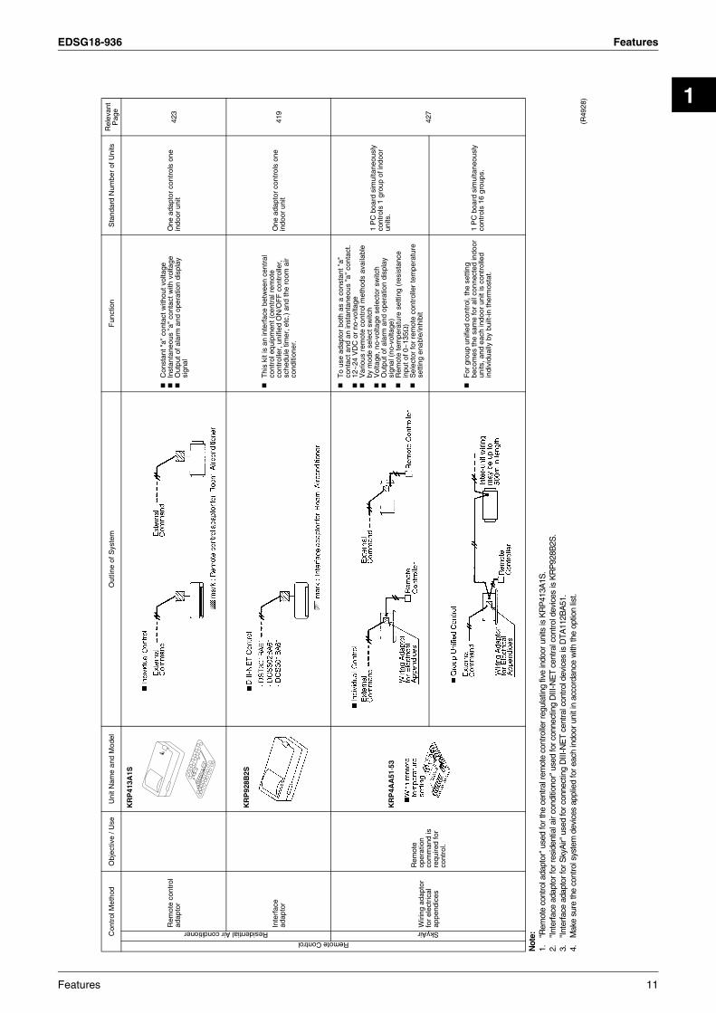
Not
e:1.
"Rem
ote
cont
rol a
dapt
or"
used
for t
he c
entra
l rem
ote
cont
rolle
r reg
ulat
ing
five
indo
or u
nits
is K
RP
413A
1S.
2."I
nter
face
ada
ptor
for r
esid
entia
l air
cond
ition
or"
used
for c
onne
ctin
g D
III-N
ET
cent
ral c
ontro
l dev
ices
is K
RP
928B
2S.
3."I
nter
face
ada
ptor
for S
kyA
ir" u
sed
for c
onne
ctin
g D
III-N
ET
cent
ral c
ontro
l dev
ices
is D
TA11
2BA
51.
4.M
ake
sure
the
cont
rol s
yste
m d
evic
es a
pplie
d fo
r eac
h in
door
uni
t in
acco
rdan
ce w
ith th
e op
tion
list.
(R49
28)
Con
trol
Met
hod
Obj
ectiv
e / U
seU
nit N
ame
and
Mod
elO
utlin
e of
Sys
tem
Fun
ctio
n S
tand
ard
Num
ber
of U
nits
Rel
evan
t P
age
Remote ControlResidential Air conditioner
Rem
ote
cont
rol
adap
tor
KR
P41
3A1S
Con
stan
t "a"
con
tact
with
out v
olta
geIn
stan
tane
ous
"a"
cont
act w
ith v
olta
geO
utpu
t of a
larm
and
ope
ratio
n di
spla
y si
gnal
One
ada
ptor
con
trol
s on
e in
door
uni
t42
3
Inte
rfac
e ad
apto
r
KR
P92
8B2S
Thi
s ki
t is
an in
terf
ace
betw
een
cent
ral
cont
rol e
quip
men
t (ce
ntra
l rem
ote
cont
rolle
r, u
nifie
d O
N/O
FF
con
trol
ler,
sc
hedu
le ti
mer
, etc
.) a
nd th
e ro
om a
ir co
nditi
oner
.
One
ada
ptor
con
trol
s on
e in
door
uni
t41
9
SkyAir
Wiri
ng a
dapt
or
for
elec
tric
al
appe
ndic
es
Rem
ote
oper
atio
n co
mm
and
is
requ
ired
for
cont
rol.
KR
P4A
A51
·53
To
use
adap
tor
both
as
a co
nsta
nt "
a"
cont
act a
nd a
n in
stan
tane
ous
"a"
cont
act.
12~
24 V
DC
or
no-v
olta
geV
ario
us r
emot
e co
ntro
l met
hods
ava
ilabl
e by
mod
e se
lect
sw
itch
Vol
tage
, no-
volta
ge s
elec
tor
switc
hO
utpu
t of a
larm
and
ope
ratio
n di
spla
y si
gnal
(no
-vol
tage
)R
emot
e te
mpe
ratu
re s
ettin
g (r
esis
tanc
e in
put o
f 0~
135Ω
)S
elec
tor
for
rem
ote
cont
rolle
r te
mpe
ratu
re
setti
ng e
nabl
e/in
hibi
t
1 P
C b
oard
sim
ulta
neou
sly
cont
rols
1 g
roup
of i
ndoo
r un
its.
427
For
gro
up u
nifie
d co
ntro
l, th
e se
tting
be
com
es th
e sa
me
for
all c
onne
cted
indo
or
units
, and
eac
h in
door
uni
t is
cont
rolle
d in
divi
dual
ly b
y bu
ilt-in
ther
mos
tat.
1 P
C b
oard
sim
ulta
neou
sly
cont
rols
16
grou
ps.
Features 11
Features EDSG18-936
12 Features

EDSG18-936
2
Part 2Multi-Split System
Room Air ConditionersSUPER MULTI PLUS
E-SeriesCooling Only
1. Power Supply ........................................................................................152. Functions...............................................................................................163. Specifications ........................................................................................20
3.1 Outdoor Units .........................................................................................203.2 BP Unit ...................................................................................................213.3 Combination Capacity Index ..................................................................223.4 Indoor Units ............................................................................................25
4. Dimensions ...........................................................................................324.1 Outdoor Units .........................................................................................324.2 BP Units .................................................................................................334.3 Indoor Units ............................................................................................34
5. Wiring Diagrams....................................................................................455.1 Outdoor Units .........................................................................................455.2 BP Units .................................................................................................465.3 Indoor Units ............................................................................................47
6. Piping Diagrams....................................................................................526.1 Outdoor Units .........................................................................................526.2 BP Units .................................................................................................536.3 Indoor Units ............................................................................................54
FTKS25DVMFTKS35DVMFTKS50FVMFTKS60FVMFTKS71FVMFTKS50BVMA8FDKS25CAVMBFDKS35CAVMBFDKS50CVMBFDKS60CVMBFDKS25EAVMBFDKS35EAVMB
FFQ25BV1B9FFQ35BV1B9FFQ50BV1B9FFQ60BV1B9FCQ35BVEFCQ50BVEFCQ60BVEFCQ71BVEFBQ60BV1FBQ71BV1
RMKS112EVMRMKS140EVMRMKS160EVMBPMKS967B2BBPMKS967B3B
SUPER MULTI PLUS E-Series Cooling Only 13

EDSG18-936
7. Capacity Tables ....................................................................................577.1 Total Capacity ........................................................................................577.2 Capacity Correction Factor by the Length of Refrigerant Piping ............63
8. Operation Limit......................................................................................659. Fan Characteristics ...............................................................................6610.Sound Level ..........................................................................................69
10.1 Measuring Location ................................................................................6910.2 Octave Band Level .................................................................................70
11.Electric Characteristics..........................................................................73
14 SUPER MULTI PLUS E-Series Cooling Only

EDSG18-936 Power Supply
2
1. Power Supply
Note: Power Supply Intake ; Outdoor Unit
Indoor Unit Outdoor Unit Power Supply
Wall Mounted Type FTKS25DVM RMKS112EVMRMKS140EVMRMKS160EVMBPMKS967B2BBPMKS967B3B
1φ, 230V, 50Hz
FTKS35DVM
FTKS50FVM
FTKS60FVM
FTKS71FVM
FTKS50BVMA8
Duct Connected Type FDKS25CAVMB
FDKS35CAVMB
FDKS50CVMB
FDKS60CVMB
FDKS25EAVMB
FDKS35EAVMB
Ceiling Mounted Cassette Type
FFQ25BV1B9
FFQ35BV1B9
FFQ50BV1B9
FFQ60BV1B9
FCQ35BVE
FCQ50BVE
FCQ60BVE
FCQ71BVE
Ceiling Mounted Built-in Type
FBQ60BV1
FBQ71BV1
SUPER MULTI PLUS E-Series Cooling Only 15

Functions EDSG18-936
2. Functions
Category Functions
RM
KS
112/
140/
160E
VM
Category Functions
RM
KS
112/
140/
160E
VM
Basic Function Inverter (with Inverter Power Control) Health &
Clean Air-Purifying Filter with Bacteriostatic & Virustatic Functions —
Operation Limit for Cooling (°CDB)–5~46
Photocatalytic Deodorizing Filter —
Operation Limit for Heating (°CWB) — Air-Purifying Filter with Photocatalytic Deodorizing Function —
PAM Control — Titanium Apatite Photocatalytic Air-Purifying Filter —
Compressor Oval Scroll Compressor Longlife Filter (Option) —
Swing Compressor — Air Filter (Prefilter) —
Rotary Compressor — Wipe-Clean Flat Panel —
Reluctance DC Motor Washable Grille —
Comfortable Airflow
Power-Airflow Flap — Filter Cleaning Indicator —
Power-Airflow Dual Flaps — Mold Proof Operation —
Power-Airflow Diffuser — Heating Dry Operation —
Wide-Angle Louvers — Good-Sleep Cooling Operation —
Vertical Auto-Swing (Up and Down) —Timer 24-Hour ON/OFF Timer —
72-Hour ON/OFF Timer —
Horizontal Auto-Swing (Right and Left) — Night Set Mode —
3-D Airflow — Worry Free“Reliability & Durability”
Auto-Restart (after Power Failure) —
COMFORT AIRFLOW Mode — Self-Diagnosis (Digital, LED) Display
3-Step Airflow (H/P Only) — Wiring-Error Check —
Comfort Control
Auto Fan Speed — Automatic Test Operation
Indoor Unit Quiet Operation — Memory Function
Night Quiet Mode (Automatic) Anti-Corrosion Treatment of Outdoor Heat Exchanger
Outdoor Unit Quiet Operation (Manual) Flexibility Multi-Split / Split Type Compatible Indoor Unit —
INTELLIGENT EYE Operation — Flexible Voltage Correspondence
Quick Warming Function — High Ceiling Application —
Hot-Start Function — Chargeless —
Automatic Defrosting — Either Side Drain (Right or Left) —
Operation Automatic Operation — Power Selection —
Program Dry Function — Remote Control
5-Rooms Centralized Controller (Option) —
Fan Only — Remote Control Adaptor(Normal Open-Pulse Contact) (Option) —
Lifestyle Convenience
New POWERFUL Operation (Non-Inverter) — Remote Control Adaptor
(Normal Open Contact) (Option) —
Inverter POWERFUL Operation — Dlll-NET Compatible (Adaptor) (Option) —
Priority-Room Setting — Remote Controller
Wireless —
COOL / HEAT Mode Lock — Wired —
HOME LEAVE Operation —
ECONO Mode —
Indoor Unit ON/OFF Button —
Signal Receiving Sign —
Temperature Display —
Another Room Operation —
Note: : Holding Functions— : No Functions
16 SUPER MULTI PLUS E-Series Cooling Only

EDSG18-936 Functions
2
Category FunctionsFT
KS
25/3
5DV
M
FT
KS
50-7
1FV
M
FT
KS
50B
VM
A8
Category Functions
FT
KS
25/3
5DV
M
FT
KS
50-7
1FV
M
FT
KS
50B
VM
A8
Basic Function
Inverter (with Inverter Power Control) Health & Clean
Air-Purifying Filter with Bacteriostatic, Virustatic Functions — — —
Operation Limit for Cooling (°CDB) — — —
Operation Limit for Heating (°CWB) — — — Photocatalytic Deodorizing Filter — — —
PAM Control — — — Air-Purifying Filter with Photocatalytic Deodorizing Function — —
Compressor Oval Scroll Compressor — — —
Swing Compressor — — — Titanium Apatite Photocatalytic Air-Purifying Filter —
Rotary Compressor — — —
Reluctance DC Motor — — — Longlife Filter (Option) — — —
Comfortable Airflow
Power-Airflow Flap — — — Air Filter (Prefilter)
Power-Airflow Dual Flaps Wipe-Clean Flat Panel
Power-Airflow Diffuser — — — Washable Grille — — —
Wide-Angle Louvers Filter Cleaning Indicator — — —
Vertical Auto-Swing (Up and Down) Mold Proof Operation — —
Horizontal Auto-Swing (Right and Left) — Heating Dry Operation — — —
3-D Airflow — Good-Sleep Cooling Operation — — —
COMFORT AIRFLOW Mode — — — Timer 24-Hour ON/OFF Timer
3-Step Airflow (H/P Only) — — — 72-Hour ON/OFF Timer — — —
Comfort Control
Auto Fan Speed Night Set Mode
Indoor Unit Quiet Operation Worry Free “Reliability & Durability”
Auto-Restart (after Power Failure)
Night Quiet Mode (Automatic) — — — Self-Diagnosis (Digital, LED) Display
Outdoor Unit Quiet Operation (Manual) — — — Wiring Error Check — — —
INTELLIGENT EYE Operation Anti-Corrosion Treatment of Outdoor Heat Exchanger — — —
Quick Warming Function — — —
Hot-Start Function — — — Flexibility Multi-Split / Split Type Compatible Indoor Unit
Automatic Defrosting — — — Flexible Voltage Correspondence
Operation Automatic Operation — — — High Ceiling Application — — —
Program Dry Function Chargeless — — —
Fan Only Either Side Drain (Right or Left)
Lifestyle Convenience
New POWERFUL Operation (Non-Inverter) — — — Power Selection — — —
Inverter POWERFUL Operation Remote Control
5-Rooms Centralized Controller (Option)
Priority-Room Setting — — — Remote Control Adaptor(Normal Open-Pulse Contact) (Option)COOL / HEAT Mode Lock — — —
HOME LEAVE Operation — Remote Control Adaptor (Normal Open Contact) (Option)ECONO Mode — —
Indoor Unit ON/OFF Button DIII-NET Compatible (Adaptor) (Option)
Signal Receiving Sign Remote Controller
Wireless
Temperature Display — — — Wired — — —
Another Room Operation — — —
Note: : Holding Functions— : No Functions
SUPER MULTI PLUS E-Series Cooling Only 17
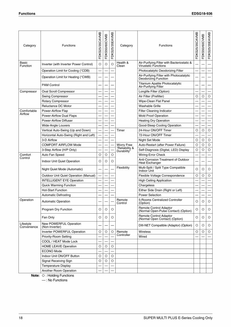
Functions EDSG18-936
Category Functions
FD
KS
25/3
5CA
VM
B
FD
KS
50/6
0CV
MB
FD
KS
25/3
5EA
VM
B
Category Functions
FD
KS
25/3
5CA
VM
B
FD
KS
50/6
0CV
MB
FD
KS
25/3
5EA
VM
B
Basic Function Inverter (with Inverter Power Control) Health &
Clean Air-Purifying Filter with Bacteriostatic & Virustatic Functions — — —
Operation Limit for Cooling (°CDB) — — — Photocatalytic Deodorizing Filter — — —
Operation Limit for Heating (°CWB) — — — Air-Purifying Filter with Photocatalytic Deodorizing Function — — —
PAM Control — — — Titanium Apatite Photocatalytic Air-Purifying Filter — — —
Compressor Oval Scroll Compressor — — — Longlife Filter (Option) — — —
Swing Compressor — — — Air Filter (Prefilter)
Rotary Compressor — — — Wipe-Clean Flat Panel — — —
Reluctance DC Motor — — — Washable Grille — — —
Comfortable Airflow
Power-Airflow Flap — — — Filter Cleaning Indicator — — —
Power-Airflow Dual Flaps — — — Mold Proof Operation — — —
Power-Airflow Diffuser — — — Heating Dry Operation — — —
Wide-Angle Louvers — — — Good-Sleep Cooling Operation — — —
Vertical Auto-Swing (Up and Down) — — — Timer 24-Hour ON/OFF Timer
Horizontal Auto-Swing (Right and Left) — — — 72-Hour ON/OFF Timer — — —
3-D Airflow — — — Night Set Mode
COMFORT AIRFLOW Mode — — — Worry Free“Reliability & Durability”
Auto-Restart (after Power Failure)
3-Step Airflow (H/P Only) — — — Self-Diagnosis (Digital, LED) Display
Comfort Control
Auto Fan Speed Wiring-Error Check — — —
Indoor Unit Quiet Operation Anti-Corrosion Treatment of Outdoor Heat Exchanger — — —
Night Quiet Mode (Automatic) — — — Flexibility Multi-Split / Split Type Compatible Indoor Unit
Outdoor Unit Quiet Operation (Manual) — — — Flexible Voltage Correspondence
INTELLIGENT EYE Operation — — — High Ceiling Application — — —
Quick Warming Function — — — Chargeless — — —
Hot-Start Function — — — Either Side Drain (Right or Left) — — —
Automatic Defrosting — — — Power Selection — — —
Operation Automatic Operation — — — Remote Control
5-Rooms Centralized Controller (Option)
Program Dry Function Remote Control Adaptor (Normal Open-Pulse Contact) (Option)
Fan Only Remote Control Adaptor (Normal Open Contact) (Option)
Lifestyle Convenience
New POWERFUL Operation (Non-Inverter) — — — DIII-NET Compatible (Adaptor) (Option)
Inverter POWERFUL Operation Remote Controller
Wireless
Priority-Room Setting — — — Wired — — —
COOL / HEAT Mode Lock — — —
HOME LEAVE Operation
ECONO Mode — — —
Indoor Unit ON/OFF Button
Signal Receiving Sign
Temperature Display — — —
Another Room Operation — — —
Note: : Holding Functions— : No Functions
18 SUPER MULTI PLUS E-Series Cooling Only
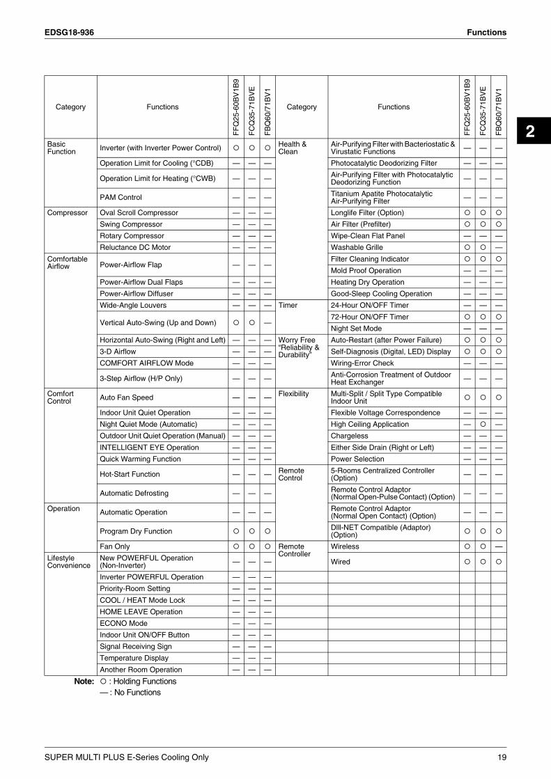
EDSG18-936 Functions
2
Category Functions
FF
Q25
-60B
V1B
9
FC
Q35
-71B
VE
FB
Q60
/71B
V1
Category Functions
FF
Q25
-60B
V1B
9
FC
Q35
-71B
VE
FB
Q60
/71B
V1
Basic Function Inverter (with Inverter Power Control) Health &
Clean Air-Purifying Filter with Bacteriostatic & Virustatic Functions — — —
Operation Limit for Cooling (°CDB) — — — Photocatalytic Deodorizing Filter — — —
Operation Limit for Heating (°CWB) — — — Air-Purifying Filter with Photocatalytic Deodorizing Function — — —
PAM Control — — — Titanium Apatite PhotocatalyticAir-Purifying Filter — — —
Compressor Oval Scroll Compressor — — — Longlife Filter (Option)
Swing Compressor — — — Air Filter (Prefilter)
Rotary Compressor — — — Wipe-Clean Flat Panel — — —
Reluctance DC Motor — — — Washable Grille —
Comfortable Airflow Power-Airflow Flap — — —
Filter Cleaning Indicator
Mold Proof Operation — — —
Power-Airflow Dual Flaps — — — Heating Dry Operation — — —
Power-Airflow Diffuser — — — Good-Sleep Cooling Operation — — —
Wide-Angle Louvers — — — Timer 24-Hour ON/OFF Timer — — —
Vertical Auto-Swing (Up and Down) —72-Hour ON/OFF Timer
Night Set Mode — — —
Horizontal Auto-Swing (Right and Left) — — — Worry Free“Reliability & Durability”
Auto-Restart (after Power Failure)
3-D Airflow — — — Self-Diagnosis (Digital, LED) Display
COMFORT AIRFLOW Mode — — — Wiring-Error Check — — —
3-Step Airflow (H/P Only) — — — Anti-Corrosion Treatment of Outdoor Heat Exchanger — — —
Comfort Control Auto Fan Speed — — — Flexibility Multi-Split / Split Type Compatible
Indoor Unit
Indoor Unit Quiet Operation — — — Flexible Voltage Correspondence — — —
Night Quiet Mode (Automatic) — — — High Ceiling Application — —
Outdoor Unit Quiet Operation (Manual) — — — Chargeless — — —
INTELLIGENT EYE Operation — — — Either Side Drain (Right or Left) — — —
Quick Warming Function — — — Power Selection — — —
Hot-Start Function — — — Remote Control
5-Rooms Centralized Controller (Option) — — —
Automatic Defrosting — — — Remote Control Adaptor (Normal Open-Pulse Contact) (Option) — — —
Operation Automatic Operation — — — Remote Control Adaptor (Normal Open Contact) (Option) — — —
Program Dry Function Dlll-NET Compatible (Adaptor) (Option)
Fan Only Remote Controller
Wireless —
Lifestyle Convenience
New POWERFUL Operation (Non-Inverter) — — — Wired
Inverter POWERFUL Operation — — —
Priority-Room Setting — — —
COOL / HEAT Mode Lock — — —
HOME LEAVE Operation — — —
ECONO Mode — — —
Indoor Unit ON/OFF Button — — —
Signal Receiving Sign — — —
Temperature Display — — —
Another Room Operation — — —
Note: : Holding Functions— : No Functions
SUPER MULTI PLUS E-Series Cooling Only 19

Specifications EDSG18-936
3. Specifications3.1 Outdoor Units
50Hz 230V
Note: 1. 1 See page 22 “Combination Capacity Index”.2. 2 Refrigerant charge is required. (Chargeless piping length 0m)
Formula for calculation charge : R (kg)R = Total length (m) of liquid pipe size at φ9.5×0.054 +Total length (m) of liquid piping size at φ6.4×0.022
3. The data are based on the conditions shown in the table below.
Model RMKS112EVM RMKS140EVM RMKS160EVM
4HP 5HP 6HP
Cooling Capacity kW(kcal/h) 11.2 (9,630) 14.0 (12,040) 15.5 (13,330)
Total Indoor Unit Capacity kW 5.5~14.5 7.0~18.2 8.0~20.8
Power Consumption 1 W —
Running Current 1 A —
Casing Color Ivory White
Compressor
Type Hermetically Sealed Scroll Type
Model JT100G-VDL
Motor Output(2.2kW/60rps) kW 2.5 3.0 3.5
Refrigerant Oil
Model DAPHNE FVC68D
Charge L 1.5
RefrigerantType R-410A
Charge kg 4.0
Air Flow Rate (H) m³/min(cfm) 106 (3,742)
Fan
Type Propeller
Motor Output W 70+70
Running Current A 0.4+0.4
Power Consumption W 88+88
Starting Current A 15.4 19.7 23.5
Dimensions (H×W×D) mm 1,345×900×320
Package Dimensions (H×W×D) mm 1,475×925×390
Weight kg 125
Gross Weight kg 136
Operation Sound dBA 52 53 54
Piping Connection
Liquid mm φ9.5 (Flare Connection)
Gas mm φ19.1 (Brazing Connection)
Drain mm φ18
Heat Insulation Both Liquid and Gas Pipes
No. of Wiring Connection 3 For Power Supply (Including Earth Wiring), 2 For Interunit Wiring (Outdoor Unit-BP)
Total piping length
O.U. - BP m 55
BP - I.U. m 60 80 90
System Total m 115 135 145
Max. piping length
BP - I.U. m 15
1st Branch - I.U. m 40
Max. level difference
O.U. - BP m 30
O.U. - I.U. m 30
BP - BP, I.U. - I.U. m 15
Necessity of Additional Charge 2 kg/m Necessary
Conversion Formulae
kcal/h=kW×860Btu/h=kW×3414
cfm=m³/min×35.3
Cooling Piping Length
Indoor ; 27°CDB / 19°CWBOutdoor ; 35°CDB
Main Piping : 5mBranch Piping : 3mLevel difference:0m
BP Unit
Outdoor Unit
Main Piping
Branch Piping
Indoor Unit
(Q0143)
20 SUPER MULTI PLUS E-Series Cooling Only

EDSG18-936 Specifications
2
3.2 BP Unit50Hz 230V
Note: 1. BP or Indoor Unit Max. Height - BP or Indoor Unit Min. Height → Max. 15m.Set up BP and indoor unit within 15m height difference.
2. The piping connection must be cut so as to suit the piping sizes of the indoor unit which will be connected. The same sizes should be used for the piping on the outdoor unit.
3. ( )* : including auxiliary piping length
Model BPMKS967B2B BPMKS967B3B
Connectable Indoor Units 1~2 Units 1~3 Units
Casing Color Paintingless
Power Consumption W 10 10
Running Current A 0.05 0.05
Refrigerant Type R-410A
Dimension (H×W×D) mm 180×294(650)*×350
Package Dimension (H×W×D) mm 257×738×427
Machine Weight kg 7.5 8
Gross Weight kg 11 12
Number of Wiring Connections 4 for Interunit Wiring
Piping Connection(Brazing)
Liquid mm Main : φ9.5×1 / Branch : φ6.4×2 Main : φ9.5×1 / Branch : φ6.4×3
Gas mm Main : φ19.1×1 / Branch : φ15.9×2 Main : φ19.1×1 / Branch : φ15.9×3
Drain mm Drain Processingless
Heat Insulation Both Liquid and Gas Pipes
Max. Piping Length m —
Amount of Additional Charge g/m —
Max. Height Difference m —
Max. Combination kW 14.2 20.8
Min. Combination kW 2.0
Accessories
Installation Manual pc. 1
L Shape Reducer pc.
For Main
Liquid 1 (For I.D. φ6.4)
Gas 1 (For I.D. φ12.7)
Gas 1 (For I.D. φ15.9, 19.1)
For BranchLiquid 1 (For I.D. φ9.5)
Gas 2 (For I.D. φ12.7, 9.5) 3 (For I.D. φ12.7, 9.5)
Hanger Metal pc. 4
Screws pc. 8 (M4×8)
Heat Insulation (2pc. is 1 set) 3 Set 4 Set
Binding Band pc. 2
Drawing No. C : 4D050058B
Conversion Formulae
kcal/h=kW×860Btu/h=kW×3414
cfm=m³/min×35.3
SUPER MULTI PLUS E-Series Cooling Only 21

Specifications EDSG18-936
3.3 Combination Capacity Index
Cooling Capacity for 4HP
4HP (cooling)
Indoor Unit FTKS, FDKS, FFQ, FCQ, FBQ
Class 25 35 50 60 71
Rated Capacity (kW) 2.5 3.5 5.0 6.0 7.1
Capacity of each indoor unit = Capacity calculated on the table below × Rated capacity of each indoor unit
Total rated capacity of the indoor units
4HP(cooling)
0
5
10
15
20
25
0 5 10 15 20Total indoor unit capacity
Cap
acity
, pow
er c
onsu
mpt
ion
(kW
)
(R5902)
Capacity [kW]Power consumption [kW]
Total indoor unit capacity
(kW)
Cooling capacity
(kW)
Power consumption
(kW)
Total indoor unit capacity
(kW)
Cooling capacity
(kW)
Power consumption
(kW)
Total indoor unit capacity
(kW)
Cooling capacity
(kW)
Power consumption
(kW)
(R5903)
5.5 5.6 5.7 5.8 5.9 6.0 6.1 6.2 6.3 6.4 6.5 6.6 6.7 6.8 6.9 7.0 7.1 7.2 7.3 7.4 7.5 7.6 7.7 7.8 7.9 8.0 8.1 8.2 8.3 8.4 8.5 8.6 8.7 8.8 8.9
9.0 9.1 9.2 9.3 9.4 9.5 9.6 9.7 9.8 9.9
10.0 10.1 10.2 10.3 10.4 10.5 10.6 10.7 10.8 10.9 11.0 11.1 11.2 11.3 11.4 11.5 11.6 11.7 11.8 11.9 12.0 12.1 12.2 12.3 12.4
12.5 12.6 12.7 12.8 12.9 13.0 13.1 13.2 13.3 13.4 13.5 13.6 13.7 13.8 13.9 14.0 14.1 14.2 14.3 14.4 14.5
5.6 5.7 5.8 5.9 6.0 6.1 6.2 6.3 6.4 6.5 6.6 6.7 6.8 6.9 7.0 7.1 7.2 7.3 7.4 7.5 7.6 7.7 7.8 7.9 8.0 8.1 8.2 8.3 8.5 8.6 8.7 8.8 8.9 9.0 9.1
9.2 9.3 9.4 9.5 9.6 9.7 9.8 9.9
10.0 10.1 10.2 10.3 10.4 10.5 10.6 10.7 10.8 10.9 11.0 11.1 11.2 11.3 11.4 11.5 11.6 11.7 11.8 11.9 12.0 12.1 12.2 12.3 12.4 12.5 12.6
12.7 12.7 12.8 12.8 12.8 12.8 12.8 12.9 12.9 12.9 12.9 12.9 13.0 13.0 13.0 13.0 13.0 13.0 13.1 13.1 13.1
1.68 1.71 1.75 1.78 1.81 1.85 1.88 1.91 1.95 1.98 2.01 2.05 2.08 2.11 2.14 2.18 2.21 2.24 2.28 2.31 2.34 2.38 2.41 2.44 2.48 2.51 2.54 2.57 2.61 2.64 2.67 2.71 2.74 2.77 2.81
2.84 2.87 2.90 2.94 2.97 3.00 3.04 3.07 3.10 3.14 3.17 3.20 3.24 3.27 3.30 3.33 3.37 3.40 3.43 3.47 3.50 3.53 3.57 3.60 3.63 3.67 3.70 3.73 3.76 3.80 3.83 3.86 3.90 3.93 3.96
4.00 4.00 4.01 4.02 4.02 4.03 4.04 4.05 4.05 4.06 4.07 4.07 4.08 4.09 4.10 4.10 4.11 4.12 4.12 4.13 4.14
22 SUPER MULTI PLUS E-Series Cooling Only

EDSG18-936 Specifications
2
Cooling Capacity for 5HP
5HP (cooling)
For Example: for a 5HP (cooling):FTKS25D + FTKS35D + FDKS50C + FBQ60B
2.5 + 3.5 + 5.0 + 6.0 = 17 < 18.2
15.1 × 2.5
Total rated capacity =of the indoor units
Cooling capacity of FTKS25D =
Cooling capacity of FTKS35D =
= = = =
1715.1 × 3.5
= 2.221
= 3.10917
15.1 × 5.0Cooling capacity of FDKS50C =17
15.1 × 6.0
= 4.441
= 5.329Cooling capacity of FBQ60B =17
Cap
acity
, pow
er c
onsu
mpt
ion
(kW
)
5HP (cooling)
0
5
10
15
20
25
0 5 10 15 20
(R5904)Total indoor unit capacity
Capacity [kW]Power consumption [kW]
Total indoor unit capacity
(kW)
Cooling capacity
(kW)
Power consumption
(kW)
Total indoor unit capacity
(kW)
Cooling capacity
(kW)
Power consumption
(kW)
Total indoor unit capacity
(kW)
Cooling capacity
(kW)
Power consumption
(kW)7.0 7.1 7.2 7.3 7.4 7.5 7.6 7.7 7.8 7.9 8.0 8.1 8.2 8.3 8.4 8.5 8.6 8.7 8.8 8.9 9.0 9.1 9.2 9.3 9.4 9.5 9.6 9.7 9.8 9.9 10.0 10.1 10.2 10.3 10.4 10.5 10.6 10.7 10.8 10.9
11.0 11.1 11.2 11.3 11.4 11.5 11.6 11.7 11.8 11.9 12.0 12.1 12.2 12.3 12.4 12.5 12.6 12.7 12.8 12.9 13.0 13.1 13.2 13.3 13.4 13.5 13.6 13.7 13.8 13.9 14.0 14.1 14.2 14.3 14.4 14.5 14.6 14.7 14.8 14.9
15.0 15.1 15.2 15.3 15.4 15.5 15.6 15.7 15.8 15.9 16.0 16.1 16.2 16.3 16.4 16.5 16.6 16.7 16.8 16.9 17.0 17.1 17.2 17.3 17.4 17.5 17.6 17.7 17.8 17.9 18.0 18.1 18.2
6.9 7.0 7.1 7.2 7.3 7.4 7.5 7.6 7.7 7.8 7.9 8.0 8.1 8.2 8.3 8.4 8.5 8.6 8.7 8.8 8.9 9.0 9.1 9.2 9.3 9.4 9.5 9.6 9.7 9.8 9.9 10.0 10.1 10.2 10.3 10.4 10.5 10.5 10.6 10.7
10.8 10.9 11.0 11.1 11.2 11.3 11.4 11.5 11.6 11.7 11.8 11.9 12.0 12.1 12.2 12.3 12.4 12.5 12.6 12.7 12.8 12.9 13.0 13.1 13.2 13.3 13.4 13.5 13.6 13.7 13.8 13.9 14.0 14.1 14.2 14.3 14.4 14.5 14.6 14.7
14.8 14.8 14.8 14.8 14.8 14.9 14.9 14.9 14.9 14.9 14.9 14.9 15.0 15.0 15.0 15.0 15.0 15.0 15.0 15.1 15.1 15.1 15.1 15.1 15.1 15.1 15.1 15.2 15.2 15.2 15.2 15.2 15.2
1.80 1.84 1.87 1.91 1.95 1.98 2.02 2.06 2.10 2.13 2.17 2.21 2.25 2.28 2.32 2.36 2.40 2.43 2.47 2.51 2.54 2.58 2.62 2.66 2.69 2.73 2.77 2.81 2.84 2.88 2.92 2.96 2.99 3.03 3.07 3.10 3.14 3.18 3.22 3.25
3.29 3.33 3.37 3.40 3.44 3.48 3.52 3.55 3.59 3.63 3.67 3.70 3.74 3.78 3.81 3.85 3.89 3.93 3.96 4.00 4.04 4.08 4.11 4.15 4.19 4.23 4.26 4.30 4.34 4.37 4.41 4.45 4.49 4.52 4.56 4.60 4.64 4.67 4.71 4.75
4.79 4.79 4.80 4.80 4.81 4.82 4.82 4.83 4.84 4.84 4.85 4.86 4.86 4.87 4.88 4.88 4.89 4.90 4.90 4.91 4.91 4.92 4.93 4.93 4.94 4.95 4.95 4.96 4.97 4.97 4.98 4.99 4.99
(R5905)
SUPER MULTI PLUS E-Series Cooling Only 23

Specifications EDSG18-936
Cooling Capacity for 6HP
6HP (cooling)
Note:Cooling capacity is based on: indoor temp. 27°CDB, 19 °CWB; outdoor temp. 35 °CDB.The rated capacities above show the rise in the total indoor unit capacity when operating frequency is constant.Values for changes in capacity are fixed after accounting for variations in operating frequency and should be used as reference values.
0
5
10
15
20
25
0 5 10 15 20
(R5906)
6HP(cooling)C
apac
ity, p
ower
con
sum
ptio
n (k
W)
Total indoor unit capacity
Capacity [kW]Power consumption [kW]
Total indoor unit capacity
(kW)
Cooling capacity
(kW)
Power consumption
(kW)
Total indoor unit capacity
(kW)
Cooling capacity
(kW)
Power consumption
(kW)
Total indoor unit capacity
(kW)
Cooling capacity
(kW)
Power consumption
(kW)8.0 8.1 8.2 8.3 8.4 8.5 8.6 8.7 8.8 8.9 9.0 9.1 9.2 9.3 9.4 9.5 9.6 9.7 9.8 9.9 10.0 10.1 10.2 10.3 10.4 10.5 10.6 10.7 10.8 10.9 11.0 11.1 11.2 11.3 11.4 11.5 11.6 11.7 11.8 11.9 12.0 12.1 12.2 12.3 12.4
12.5 12.6 12.7 12.8 12.9 13.0 13.1 13.2 13.3 13.4 13.5 13.6 13.7 13.8 13.9 14.0 14.1 14.2 14.3 14.4 14.5 14.6 14.7 14.8 14.9 15.0 15.1 15.2 15.3 15.4 15.5 15.6 15.7 15.8 15.9 16.0 16.1 16.2 16.3 16.4 16.5 16.6 16.7 16.8 16.9
17.0 17.1 17.2 17.3 17.4 17.5 17.6 17.7 17.8 17.9 18.0 18.1 18.2 18.3 18.4 18.5 18.6 18.7 18.8 18.9 19.0 19.1 19.2 19.3 19.4 19.5 19.6 19.7 19.8 19.9 20.0 20.1 20.2 20.3 20.4 20.5 20.6 20.7 20.8
7.8 7.8 7.9 8.0 8.1 8.2 8.3 8.4 8.5 8.6 8.7 8.8 8.9 9.0 9.1 9.2 9.3 9.4 9.5 9.6 9.7 9.8 9.9 10.0 10.1 10.2 10.3 10.4 10.5 10.6 10.7 10.8 10.9 10.9 11.0 11.1 11.2 11.3 11.4 11.5 11.6 11.7 11.8 11.9 12.0
12.1 12.2 12.3 12.4 12.5 12.6 12.7 12.8 12.9 13.0 13.1 13.2 13.3 13.4 13.5 13.6 13.7 13.8 13.9 14.0 14.0 14.1 14.2 14.3 14.4 14.5 14.6 14.7 14.8 14.9 15.0 15.1 15.2 15.3 15.4 15.5 15.5 15.5 15.6 15.6 15.6 15.6 15.6 15.6 15.7
15.7 15.7 15.7 15.7 15.8 15.8 15.8 15.8 15.8 15.8 15.9 15.9 15.9 15.9 15.9 16.0 16.0 16.0 16.0 16.0 16.0 16.1 16.1 16.1 16.1 16.1 16.2 16.2 16.2 16.2 16.2 16.2 16.3 16.3 16.3 16.3 16.3 16.4 16.4
2.04 2.09 2.13 2.17 2.21 2.26 2.30 2.34 2.39 2.43 2.47 2.51 2.56 2.60 2.64 2.68 2.73 2.77 2.81 2.85 2.90 2.94 2.98 3.03 3.07 3.11 3.15 3.20 3.24 3.28 3.32 3.37 3.41 3.45 3.50 3.54 3.58 3.62 3.67 3.71 3.75 3.79 3.84 3.88 3.92
3.96 4.01 4.05 4.09 4.14 4.18 4.22 4.26 4.31 4.35 4.39 4.43 4.48 4.52 4.56 4.60 4.65 4.69 4.73 4.78 4.82 4.86 4.90 4.95 4.99 5.03 5.07 5.12 5.16 5.20 5.25 5.29 5.33 5.37 5.42 5.46 5.46 5.46 5.46 5.46 5.46 5.46 5.46 5.46 5.46
5.46 5.46 5.46 5.46 5.47 5.47 5.47 5.47 5.47 5.47 5.47 5.47 5.47 5.47 5.47 5.47 5.47 5.47 5.47 5.47 5.47 5.47 5.48 5.48 5.48 5.48 5.48 5.48 5.48 5.48 5.48 5.48 5.48 5.48 5.48 5.48 5.48 5.48 5.48
(R5907)
24 SUPER MULTI PLUS E-Series Cooling Only
EDSG18-936 Specifications
2
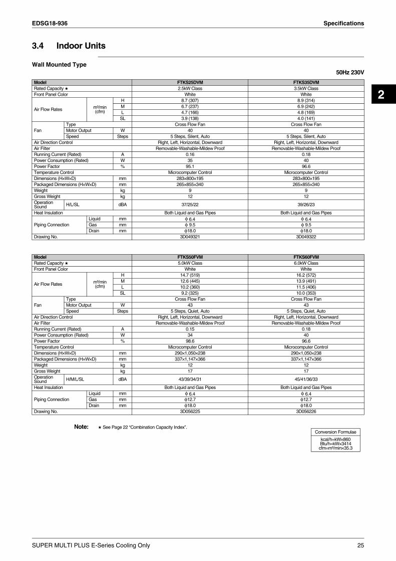
3.4 Indoor Units
Wall Mounted Type50Hz 230V
Note: See Page 22 “Combination Capacity Index”.
Model FTKS25DVM FTKS35DVMRated Capacity 2.5kW Class 3.5kW ClassFront Panel Color White White
Air Flow Rates m³/min(cfm)
H 8.7 (307) 8.9 (314)M 6.7 (237) 6.9 (242)L 4.7 (166) 4.8 (169)
SL 3.9 (138) 4.0 (141)
FanType Cross Flow Fan Cross Flow FanMotor Output W 40 40Speed Steps 5 Steps, Silent, Auto 5 Steps, Silent, Auto
Air Direction Control Right, Left, Horizontal, Downward Right, Left, Horizontal, DownwardAir Filter Removable-Washable-Mildew Proof Removable-Washable-Mildew ProofRunning Current (Rated) A 0.16 0.18Power Consumption (Rated) W 35 40Power Factor % 95.1 96.6Temperature Control Microcomputer Control Microcomputer ControlDimensions (H×W×D) mm 283×800×195 283×800×195Packaged Dimensions (H×W×D) mm 265×855×340 265×855×340Weight kg 9 9Gross Weight kg 12 12Operation Sound H/L/SL dBA 37/25/22 39/26/23
Heat Insulation Both Liquid and Gas Pipes Both Liquid and Gas Pipes
Piping ConnectionLiquid mm φ 6.4 φ 6.4Gas mm φ 9.5 φ 9.5Drain mm φ18.0 φ18.0
Drawing No. 3D049321 3D049322
Conversion Formulae
kcal/h=kW×860Btu/h=kW×3414
cfm=m³/min×35.3
Model FTKS50FVM FTKS60FVMRated Capacity 5.0kW Class 6.0kW ClassFront Panel Color White White
Air Flow Rates m³/min(cfm)
H 14.7 (519) 16.2 (572)M 12.6 (445) 13.9 (491)L 10.2 (360) 11.5 (406)
SL 9.2 (325) 10.0 (353)
FanType Cross Flow Fan Cross Flow FanMotor Output W 43 43Speed Steps 5 Steps, Quiet, Auto 5 Steps, Quiet, Auto
Air Direction Control Right, Left, Horizontal, Downward Right, Left, Horizontal, DownwardAir Filter Removable-Washable-Mildew Proof Removable-Washable-Mildew ProofRunning Current (Rated) A 0.15 0.18Power Consumption (Rated) W 34 40Power Factor % 98.6 96.6Temperature Control Microcomputer Control Microcomputer ControlDimensions (H×W×D) mm 290×1,050×238 290×1,050×238Packaged Dimensions (H×W×D) mm 337×1,147×366 337×1,147×366Weight kg 12 12Gross Weight kg 17 17Operation Sound H/M/L/SL dBA 43/39/34/31 45/41/36/33
Heat Insulation Both Liquid and Gas Pipes Both Liquid and Gas Pipes
Piping ConnectionLiquid mm φ 6.4 φ 6.4Gas mm φ12.7 φ12.7Drain mm φ18.0 φ18.0
Drawing No. 3D056225 3D056226
SUPER MULTI PLUS E-Series Cooling Only 25

Specifications EDSG18-936
50Hz 230V
Note: See Page 22 “Combination Capacity Index”.
Model FTKS71FVM FTKS50BVMA8Rated Capacity 7.1kW Class 5.0kW ClassFront Panel Color White White
Air Flow Rates m³/min(cfm)
H 17.4 (614) 11.4 (402)M 14.6 (516) 9.8 (346)L 11.9 (420) 8.7 (306)
SL 10.7 (378) 7.7 (271)
FanType Cross Flow Fan Cross Flow FanMotor Output W 43 40Speed Steps 5 Steps, Quiet, Auto 5 Steps, Quiet, Auto
Air Direction Control Right, Left, Horizontal, Downward Right, Left, Horizontal, DownwardAir Filter Removable-Washable-Mildew Proof Removable-Washable-Mildew ProofRunning Current (Rated) A 0.20 0.17Power Consumption (Rated) W 45 40Power Factor % 97.8 98Temperature Control Microcomputer Control Microcomputer ControlDimensions (H×W×D) mm 290×1,050×238 290×795×238Packaged Dimensions (H×W×D) mm 337×1,147×366 280×840×338Weight kg 12 9Gross Weight kg 17 13Operation Sound H/M/L/SL dBA 46/42/37/34 44/40/35/32
Sound Power H dBA — 63Heat Insulation Both Liquid and Gas Pipes Both Liquid and Gas Pipes
Piping ConnectionLiquid mm φ 6.4 φ 6.4Gas mm φ15.9 φ12.7Drain mm φ18.0 φ18.0
Drawing No. 3D056227 3D060919
Conversion Formulae
kcal/h=kW×860Btu/h=kW×3414
cfm=m³/min×35.3
26 SUPER MULTI PLUS E-Series Cooling Only

EDSG18-936 Specifications
2
Duct Connected Type50Hz 230V
Note: 1. See Page 22 “Combination Capacity Index”.2. The operating sound is based on the rear side suction inlet and the external static pressure 40 Pa.
Operating sound for under side suction inlet: [operating sound for rear side suction inlet]+5 dB. However, when installation to which the external static pressure becomes low is carried out, 5 dB or more may go up.
Model FDKS25CAVMB FDKS35CAVMBRated Capacity 2.5kW Class 3.5kW ClassFront Panel Color — —
Air Flow Rates m³/min(cfm)
H 9.5 (335) 10.0 (353)M 8.8 (311) 9.3 (328)L 8.0 (282) 8.5 (300)
SL 6.7 (237) 7.0 (247)
FanType Sirocco Fan Sirocco FanMotor Output W 62 62Speed Steps 5 Steps, Silent, Auto 5 Steps, Silent, Auto
Air Filter Removable-Washable-Mildew Proof Removable-Washable-Mildew ProofRunning Current (Rated) A 0.47 0.47Power Consumption (Rated) W 100 100Power Factor % 92.5 92.5Temperature Control Microcomputer Control Microcomputer ControlDimensions (H×W×D) mm 200×900×620 200×900×620Packaged Dimensions (H×W×D) mm 266×1,106×751 266×1,106×751Weight kg 25 25Gross Weight kg 31 31Operation Sound H/M/L/SL dBA 35/33/31/29 35/33/31/29
External Static Pressure Pa 40 40Moisture Removal L/h 1.2 1.9Heat Insulation Both Liquid and Gas Pipes Both Liquid and Gas Pipes
Piping ConnectionLiquid mm φ 6.4 φ 6.4Gas mm φ 9.5 φ 9.5Drain mm VP20 (O.D. φ26 / I.D. φ20) VP20 (O.D. φ26 / I.D. φ20)
Drawing No. 3D048947C 3D048948C
Conversion Formulae
kcal/h=kW×860Btu/h=kW×3414
cfm=m³/min×35.3
Model FDKS50CVMB FDKS60CVMBRated Capacity 5.0kW Class 6.0kW ClassFront Panel Color — —
Air Flow Rates m³/min(cfm)
H 12.0 (424) 16.0 (565)M 11.0 (388) 14.8 (523)L 10.0 (353) 13.5 (477)
SL 8.4 (297) 11.2 (395)
FanType Sirocco Fan Sirocco FanMotor Output W 130 130Speed Steps 5 Steps, Silent, Auto 5 Steps, Silent, Auto
Air Filter Removable-Washable-Mildew Proof Removable-Washable-Mildew ProofRunning Current (Rated) A 0.64 0.74Power Consumption (Rated) W 140 160Power Factor % 95.1 94.0Temperature Control Microcomputer Control Microcomputer ControlDimensions (H×W×D) mm 200×900×620 200×1,100×620Packaged Dimensions (H×W×D) mm 266×1,106×751 266×1,306×751Weight kg 27 30Gross Weight kg 34 37Operation Sound H/M/L/SL dBA 37/35/33/31 38/36/34/32
External Static Pressure Pa 40 40Moisture Removal L/h 2.9 3.9Heat Insulation Both Liquid and Gas Pipes Both Liquid and Gas Pipes
Piping ConnectionLiquid mm φ 6.4 φ 6.4Gas mm φ12.7 φ12.7Drain mm VP20 (O.D. φ26 / I.D. φ20) VP20 (O.D. φ26 / I.D. φ20)
Drawing No. 3D052134A 3D052135
SUPER MULTI PLUS E-Series Cooling Only 27

Specifications EDSG18-936
50Hz 230V
Note: 1. See Page 22 “Combination Capacity Index”.2. The operating sound is based on the rear side suction inlet and the external static pressure 30 Pa.
Operating sound for under side suction inlet: [operating sound for rear side suction inlet]+6 dB. However, when installation to which the external static pressure becomes low is carried out, 6 dB or more may go up.
Model FDKS25EAVMB FDKS35EAVMBRated Capacity 2.5kW Class 3.5kW ClassFront Panel Color — —
Air Flow Rates m³/min(cfm)
H 8.7 (307) 8.7 (307)M 8.0 (282) 8.0 (282)L 7.3 (258) 7.3 (258)
SL 6.2 (219) 6.2 (219)
FanType Sirocco Fan Sirocco FanMotor Output W 62 62Speed Steps 5 Steps, Silent, Auto 5 Steps, Silent, Auto
Air Filter Removable-Washable-Mildew Proof Removable-Washable-Mildew ProofRunning Current (Rated) A 0.48 0.48Power Consumption (Rated) W 71 71Power Factor % 64.3 64.3Temperature Control Microcomputer Control Microcomputer ControlDimensions (H×W×D) mm 200×700×620 200×700×620Packaged Dimensions (H×W×D) mm 274×906×751 274×906×751Weight kg 21 21Gross Weight kg 29 29Operation Sound H/M/L/SL dBA 35/33/31/29 35/33/31/29
External Static Pressure Pa 30 30Moisture Removal L/h 1.2 1.9Heat Insulation Both Liquid and Gas Pipes Both Liquid and Gas Pipes
Piping ConnectionLiquid mm φ 6.4 φ 6.4Gas mm φ 9.5 φ 9.5Drain mm VP20 (O.D.φ 26 / I.D.φ 20) VP20 (O.D.φ 26 / I.D.φ 20)
Drawing No. 3D051882A 3D051884A
Conversion Formulae
kcal/h=kW×860Btu/h=kW×3414cfm=m³/min×35.3
28 SUPER MULTI PLUS E-Series Cooling Only

EDSG18-936 Specifications
2
Ceiling Mounted Cassette Type50Hz 230V
Note: 1 See Page 22 “Combination Capacity Index”.2 ( ) : dimension including control box
Model FFQ25BV1B9 FFQ35BV1B9Rated Capacity 1 2.5kW Class 3.5kW Class
Decoration Panel
Color White WhiteDimensions (H×W×D) 55×700×700 55×700×700
Air Flow Rates m³/min(cfm)
H 9.0 (318) 10.0 (353)M — —L 6.5 (230) 6.5 (230)
SL — —
FanType Turbo Fan Turbo FanMotor Output W 55 55Speed Steps 2 Steps 2 Steps
Air Direction Control Horizontal, Downward Horizontal, DownwardRunning Current (Rated) A 0.37 0.40Power Consumption (Rated) W 73 84Power Factor % 85.8 91.3Temperature Control Microcomputer Control Microcomputer ControlDimensions (H×W×D) 2 mm 260 (286)×575×575 260 (286)×575×575Packaged Dimensions (H×W×D) mm 370×687×674 370×687×674Weight kg 17.5 17.5Gross Weight kg 21 21Operation Sound H/L dBA 29.5/24.5 32/25
Sound Power H dBA 46.5 49.0Heat Insulation Both Liquid and Gas Pipes Both Liquid and Gas Pipes
Piping ConnectionLiquid mm φ 6.4 φ 6.4Gas mm φ 9.5 φ 9.5Drain mm VP20 (O.D.φ 26 / I.D.φ 20) VP20 (O.D.φ 26 / I.D.φ 20)
Drawing No. 3D040444B 3D040442B
Model FFQ50BV1B9 FFQ60BV1B9Rated Capacity 1 5.0kW Class 6.0kW Class
Decoration Panel
Color White WhiteDimensions (H×W×D) 55×700×700 55×700×700
Air Flow Rates m³/min(cfm)
H 12.0 (424) 15.0 (530)M — —L 8.0 (283) 10.0 (353)
SL — —
FanType Turbo Fan Turbo FanMotor Output W 55 55Speed Steps 2 Steps 2 Steps
Air Direction Control Horizontal, Downward Horizontal, DownwardRunning Current (Rated) A 0.49 0.61Power Consumption (Rated) W 97 120Power Factor % 86.1 85.5Temperature Control Microcomputer Control Microcomputer ControlDimensions (H×W×D) 2 mm 260 (286)×575×575 260 (286)×575×575Packaged Dimensions (H×W×D) mm 370×687×674 370×687×674Weight kg 17.5 17.5Gross Weight kg 21 21Operation Sound H/L dBA 36/27 41/32
Sound Power H dBA 53 58Heat Insulation Both Liquid and Gas Pipes Both Liquid and Gas Pipes
Piping ConnectionLiquid mm φ 6.4 φ 6.4Gas mm φ12.7 φ12.7Drain mm VP20 (O.D.φ 26 / I.D.φ 20) VP20 (O.D.φ 26 / I.D.φ 20)
Drawing No. 3D040437 3D040431
Conversion Formulae
kcal/h=kW×860Btu/h=kW×3414cfm=m³/min×35.3
SUPER MULTI PLUS E-Series Cooling Only 29

Specifications EDSG18-936
50Hz 230V
Note: See Page 22 “Combination Capacity Index”.
Model FCQ35BVE FCQ50BVERated Capacity 3.5kW Class 5.0kW Class
Decoration Panel
Color White WhiteDimensions (H×W×D) 40×950×950 40×950×950
Air Flow Rates m³/min(cfm)
H 14.0 (494) 15.0 (530)M — —L 10.0 (353) 11.0 (388.3)
SL — —
FanType Turbo Fan Turbo FanMotor Output W 45 45Speed Steps 2 Steps 2 Steps
Air Direction Control Horizontal, Downward Horizontal, DownwardAir Filter Removable-Washable-Mildew Proof Removable-Washable-Mildew ProofRunning Current (Max. Rated) A 0.8 0.8Power Consumption (Rated) W 140 140Temperature Control Microcomputer Control Microcomputer ControlDimensions (H×W×D) mm 230×840×840 230×840×840Packaged Dimensions (H×W×D) mm 305×930×920 305×930×920Weight kg 24 24Gross Weight kg 32 32Operation Sound H/L dBA 34/30 34/30
Heat Insulation Both Liquid and Gas Pipes Both Liquid and Gas Pipes
Piping ConnectionLiquid mm φ 6.4 (Flare) φ 6.4 (Flare)Gas mm φ 9.5 (Flare) φ 12.7 (Flare)Drain mm VP25 (O.D.φ 32 / I.D.φ 25) VP25 (O.D.φ 32 / I.D.φ 25)
Drawing No. 3D049093A 3D049093A
Model FCQ60BVE FCQ71BVERated Capacity 6.0kW Class 7.1kW Class
Decoration Panel
Color White WhiteDimensions (H×W×D) 40×950×950 40×950×950
Air Flow Rates m³/min(cfm)
H 19.0 (670.7) 19.0 (670.7)M — —L 14.0 (494.2) 14.0 (494.2)
SL — —
FanType Turbo Fan Turbo FanMotor Output W 45 45Speed Steps 2 Steps 2 Steps
Air Direction Control Horizontal, Downward Horizontal, DownwardAir Filter Removable-Washable-Mildew Proof Removable-Washable-Mildew ProofRunning Current (Max. Rated) A 0.8 0.8Power Consumption (Rated) W 161 161Temperature Control Microcomputer Control Microcomputer ControlDimensions (H×W×D) mm 230×840×840 230×840×840Packaged Dimensions (H×W×D) mm 305×930×920 305×930×920Weight kg 24 24Gross Weight kg 32 32Operation Sound H/L dBA 36/31 36/31
Heat Insulation Both Liquid and Gas Pipes Both Liquid and Gas Pipes
Piping ConnectionLiquid mm φ 6.4 (Flare) φ 9.5 (Flare)Gas mm φ12.7 (Flare) φ15.9 (Flare)Drain mm VP25 (O.D.φ 32 / I.D.φ 25) VP25 (O.D.φ 32 / I.D.φ 25)
Drawing No. 3D049093A 3D049093A
Conversion Formulae
kcal/h=kW×860Btu/h=kW×3414cfm=m³/min×35.3
30 SUPER MULTI PLUS E-Series Cooling Only
EDSG18-936 Specifications
2
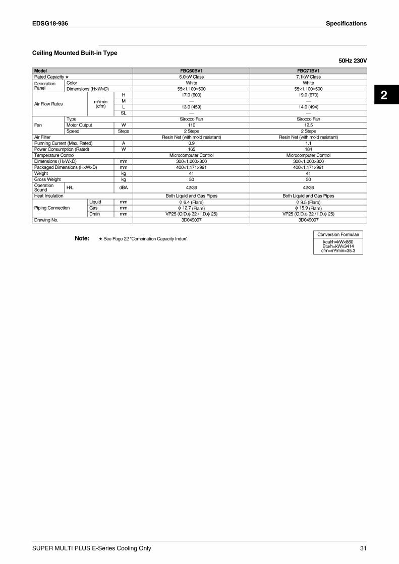
Ceiling Mounted Built-in Type50Hz 230V
Note: See Page 22 “Combination Capacity Index”.
Model FBQ60BV1 FBQ71BV1Rated Capacity 6.0kW Class 7.1kW Class
Decoration Panel
Color White WhiteDimensions (H×W×D) 55×1,100×500 55×1,100×500
Air Flow Rates m³/min(cfm)
H 17.0 (600) 19.0 (670)M — —L 13.0 (459) 14.0 (494)
SL — —
FanType Sirocco Fan Sirocco FanMotor Output W 110 12.5Speed Steps 2 Steps 2 Steps
Air Filter Resin Net (with mold resistant) Resin Net (with mold resistant)Running Current (Max. Rated) A 0.9 1.1Power Consumption (Rated) W 165 184Temperature Control Microcomputer Control Microcomputer ControlDimensions (H×W×D) mm 300×1,000×800 300×1,000×800Packaged Dimensions (H×W×D) mm 400×1,171×991 400×1,171×991Weight kg 41 41Gross Weight kg 50 50Operation Sound H/L dBA 42/36 42/36
Heat Insulation Both Liquid and Gas Pipes Both Liquid and Gas Pipes
Piping ConnectionLiquid mm φ 6.4 (Flare) φ 9.5 (Flare)Gas mm φ 12.7 (Flare) φ 15.9 (Flare)Drain mm VP25 (O.D.φ 32 / I.D.φ 25) VP25 (O.D.φ 32 / I.D.φ 25)
Drawing No. 3D049097 3D049097
Conversion Formulae
kcal/h=kW×860Btu/h=kW×3414cfm=m³/min×35.3
SUPER MULTI PLUS E-Series Cooling Only 31
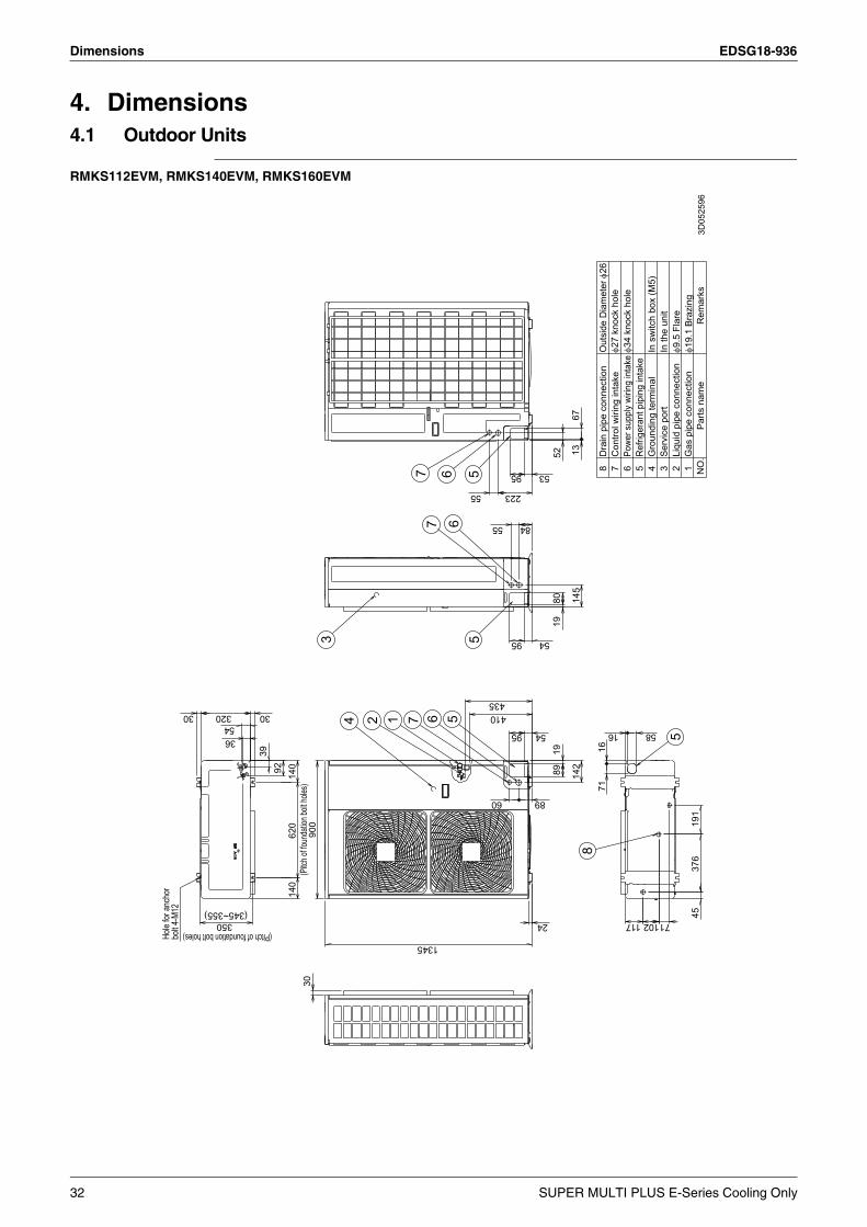
Dimensions EDSG18-936
4. Dimensions4.1 Outdoor Units
RMKS112EVM, RMKS140EVM, RMKS160EVM
1345
95
1
6
140
6
897
39
52
320
7
117
30 7
3
16
92
67
71
80
5436
376
145
30
89
71
55
5
30
191
223
95
620
54
4
55895
10214
024
6
54
410
53
60
84
19
55
900
Hole
for an
chor
bolt 4
-M12
19
814
2
435
45
13
5
52
350
16
Liqu
id p
ipe
conn
ectio
n
(Pitc
h of fo
unda
tion b
olt ho
les)
2
Ref
riger
ant p
ipin
g in
take
367
In th
e un
itIn
sw
itch
box
(M5)
8
Gas
pip
e co
nnec
tion
Rem
arks
1
(Pitch of foundation bolt holes)
(345~355)
4G
roun
ding
term
inal
Powe
r sup
ply
wirin
g in
take
Serv
ice
port
5
Parts
nam
eN
O.D
rain
pip
e co
nnec
tion
Con
trol w
iring
inta
keO
utsi
de D
iam
eter
φ26
φ27
knoc
k ho
leφ3
4 kn
ock
hole
φ9.5
Fla
reφ1
9.1
Braz
ing
3D05
2596
32 SUPER MULTI PLUS E-Series Cooling Only

EDSG18-936 Dimensions
2
4.2 BP Units
BPMKS967B2B
BPMKS967B3B
2×2-Brazing
2373
.5
INDOOR UNIT SIDE
57
Room
A(Characteristic 3. )
95(304)
Room
B
45 Wiring clamp
2-I.D.φ6.4CuT
Suspension bolt pitch
2-I.D.φ15.9CuT
254
25(1
80)
Branch piping
Earth(M4)178
Terminal(For Power supply)
Manufacturer’slabel
Wall-mounting(Characteristic 4. )
Terminal(For A room)
(650)
322Suspension bolt pitch
294
Terminal(For B room)Terminal(For transmission)
Earth(M4)
4-Suspensionbolt(M8~M10)
178
I.D.φ19.1CuT
I.D.φ9.5CuT25
113
Wiring clamp
:screw for fixing. (4 places)
Electric box
Screw for temporary fixing(Cautions 3.)
OUTDOOR UNIT SIDE
2-Brazing197 107
73.5
23
O.D.φ15.9For outdoor unit side(Gas)
16368
I.D.φ9.5
155
Cut line for I.D.φ12.7
(servicing space)Min390
Cut line for
Standard accessories (Caution5. )
For indoor side(Gas)
( servi
cing s
pace
)Mi
n300
90 I.D.φ12.7
O.D.φ15.9
7012
5
For outdoor unit side(Liquid)O.D.φ9.5
For outdoor side(Gas)
100
I.D.φ19.1
Dimple
I.D.φ6.4
165 90
For indoor side(Liquid)Cut line for O.D.φ6.4
(servicing space)Min390
45
65110
I.D.φ9.5
Cut line forI.D.φ15.9
150
O.D.φ19.1
110
(304
)
The opening for InspectionServicing is neededopening of 650mm squarefor service and maintenance.
323~355
Characteristics:1. No drain treatment necessary.2. This unit can be installed so that or side
faces forward. (It choosed by servicing direction).3. The piping for the indoor unit and outdoor unit can be.
freely installed to directions of , , or .4. This unit can be installed with either suspending
from the ceiling or mounting on wall.
Cautions:1. This unit must be installed so that side of is facing up.2. The slant of face must be within ±5°
for front and rear, right and left.3. Before mounting on the wall , installation becomes easy
by hanging this unit on screw for temporary fixing. (2 places)4. At the time of brazing the pipes, wrap the pipes with
sufficient wet cloths.And after brazing also, must cool piping enough.
5. Cut the piping of the standard accessories in order tomatch the indoor unit’s piping diameter. 3D048412A
Installation restrictions(installation and service space)
2×3-Brazing
73.5
23
57
INDOOR UNIT SIDE
Room
A
(Characteristic 3. )
95
Room
B
(304)95
Room
C
5745
Wiring clamp
3-I.Dφ.6.4CuT
Suspension bolt pitch
3-I.D.φ15.9CuT
2525
4
Branch piping
Earth(M4)178
Terminal(For Power supply)
Manufacturer’slabel
Wall-mounting(Characteristic 4. )
Terminal(For A room)
(650)
322Suspension bolt pitch
294
Terminal(For B room)Terminal(For C room)Terminal(For transmission)
Earth(M4)
4-Suspensionbolt(M8~M10)
178
I.D.φ19.1CuT
I.D.φ9.5CuT
113
25
Wiring clamp
: screw for fixing.(4 places)
Electric box
Screw for temporary fixing(Cautions 3.)
OUTDOOR UNIT SIDE
2-Brazing197
323~355
107
2373
.5
O.D.φ15.9For outdoor unit side(Gas)
25816368
I.D.φ9.5
155
Cut line for I.D.φ12.7Cut line for
( servi
cing s
pace
)Mi
n300
Standard accessories(Caution5. )
For indoor side(Gas)
90
(servicing space)Min460
I.D.φ12.7
O.D.φ15.9
70
The opening for InspectionServicing is neededopening of 650mm squarefor service and maintenance.
125
For outdoor unit side(Liquid)O.D.φ9.5
For outdoor side(Gas)
100
I.D.φ19. 1
Dimple
I.D.φ6.4
165 90
For indoor side(Liquid)Cut line for O.D.φ6. 4
45
65110
I.D.φ9.5
Cut line forI.D.φ15. 9
150
O.D.φ19. 1
110
(304
)
Characteristics:1. No drain treatment necessary.2. This unit can be installed so that or side
faces forward. (It choosed by servicing direction).3. The piping for the indoor unit and outdoor unit can be.
freely installed to directions of , , or .4. This unit can be installed with either suspending
from the ceiling or mounting on wall.
Cautions:1. This unit must be installed so that side of is facing up.2. The slant of face must be within ±5°
for front and rear, right and left.3. Before mounting on the wall , installation becomes easy
by hanging this unit on screw for temporary fixing. (2 places)4. At the time of brazing the pipes, wrap the pipes with
sufficient wet cloths.And after brazing also, must cool piping enough.
5. Cut the piping of the standard accessories in order tomatch the indoor unit’s piping diameter.
(servicing space)Min390
(180
) Installation restrictions(installation and service space)
3D048411A
SUPER MULTI PLUS E-Series Cooling Only 33

Dimensions EDSG18-936
4.3 Indoor Units4.3.1 Wall Mounted Type
FTKS25DVM, FTKS35DVM
FTKS50FVM, FTKS60FVM
WIRELESS REMOTE CONTROLLER
LEFT
BOTTOM
THE MARK (→) SHOWS PIPING DIRECTION
58
REAR
( ARC433B47 )
FLAPS
SIGNAL TRANSMITTER
163
FRONT PANEL FIXED SCREWS
18
( INSIDE )
800
10°
UP/DOWN( AUTOMATIC )
COOLING, DRY
RIGHT/LEFT( MANUAL )
50°
SIGNAL RECEIVER
INDOOR UNIT ON/OFF SWITCH
OPERATION LAMP
ROOM TEMP. THERMISTOR( INSIDE )
45°
TIMER LAMP
INTELLIGENT EYE LAMP
RIGHT
INTELLIGENT EYE SENSOR
45°
BLADE ANGLE
5°
FAN
70°
283
( MOUNTING PLATEINCLUDING
195
197
WITH EARTH
)
NAME PLATE
TERMINAL
TERMINAL BLOCK
AIR FLOW(INDOOR )
(SPACEFORMAINTENANCE)
GAS PIPE 9.5Cut
THE UNIT:ABOUT390)(THE LENGTH OF PIPE OUTSIDE
(THE LENGTH OF PIPE OUTSIDE
WALL HOLE FOR EMBEDDED PIPING
44.5
17
φ65 HOLE
STANDARD LOCATIONS OF WALL HOLES
THE UNIT:ABOUT 340)
LIQUID PIPE 6.4CuT
50MIN.
60
REQUIRED SPACE
800
711
THE HOSE LENGTH OF OUTSIDETHE UNIT IS APPROX. 440)
DRAIN HOSE(CONNECTING PART
O. D.φ18I. D. φ14
110
(SPACE FORMAINTENANCE)
50MIN.
WALL HOLE
49
φ65 HOLE
30M
IN.
( S
PAC
E F
OR
44.5
1318
0P
ER
FO
RM
AN
CE
)28
3
DAIKIN
3D047958F
REAR
WIRELESS REMOTE
CONTROLLER
REARLEFT
TIMER LAMP
INDOOR UNIT ON/OFFSWITCH
OPERATION LAMPSIGNAL RECEIVER
ROOM TEMP. THERMISTOR
HOME LEAVE LAMP
(INSIDE)INTELLIGENT EYE SENSOR
1050
THE MARK (→) SHOWS PIPING DIRECTION
FLAPS
RIGHT
FRONT GRILLE FIXING SCREWS(INSIDE)
SIGNALTRANSMITTER
58 18
163
COOLING DRY
HORIZONTAL BLADE(AUTOMATIC)
VERTICAL BLADE(AUTOMATIC)FAN
(ARC433B71)
BLADE ANGLES
50° 50°
10°
5°
5°
55°
35°35°
55°5°
5°10°40°
40°
MODEL NAMEPLATE
TERMINAL BLOCK WITHEARTH TERMINAL
(
(INSIDE)
INCLUDINGINSTALLATION PLATE)
238240
290
MIN
.30
MIN.50MIN.50
(FOR PERFORMANCE AND MAINTENANCE)
REQUIRED SPACE(SPACE FORMAINTENANCE)
AIR FLOW(INDOOR)
(SPACE FORMAINTENANCE)
(SPA
CE
FOR
PER
FOR
MAN
CE)
GAS PIPE φ12.7 CuT
I. D. 14.0, O. D. 18.0)(CONNECTING PART
(THE HOSE LENGTH OFOUTSIDE THE UNIT :ABOUT 530)
DRAIN HOSE FOR VP13
(THE LENGTH OF PIPE OUTSIDETHE UNIT : ABOUT 430)
(THE LENGTH OF PIPE OUTSIDETHE UNIT : ABOUT 480)
LIQUID PIPE φ6.4 CuT
STANDARD LOCATIONS OF WALL HOLES
99.5
290
30
52.5
1050
155.
5
52
5214
.5
893.5
60 WALL HOLE
φ80 HOLE
WALL HOLE FOREMBEDDED PIPING
φ80 HOLE
3D055868A
34 SUPER MULTI PLUS E-Series Cooling Only

EDSG18-936 Dimensions
2
FTKS71FVM
FTKS50BVMA8
MIN
.30
MIN.50MIN.50
COOLING
(FOR PERFORMANCE AND MAINTENANCE)
TIMER LAMP
FLAPS
SIGNALTRANSMITTER
INDOOR UNIT ON/OFFSWITCH
REARRIGHTLEFT
OPERATION LAMP
FRONT GRILLE FIXING SCREWS
MODEL NAMEPLATE
REQUIRED SPACE
DRY
SIGNAL RECEIVER
TERMINAL BLOCK WITHEARTH TERMINALROOM TEMP. THERMISTOR
HOME LEAVE LAMP
WIRELESS REMOTE
CONTROLLER
(SPACE FORMAINTENANCE)(
AIR FLOW(INDOOR)
HORIZONTAL BLADE(AUTOMATIC)
(INSIDE)
INCLUDINGINSTALLATION PLATE
(SPACE FORMAINTENANCE)
VERTICAL BLADE(AUTOMATIC)
STANDARD LOCATIONS OF WALL HOLES
(INSIDE)
FAN
REAR
(SPA
CE
FOR
PER
FOR
MAN
CE)
INTELLIGENT EYE SENSOR
)
(ARC433B71)
(INSIDE)
BLADE ANGLES
1050
THE MARK (→) SHOWS PIPING DIRECTION
58 18
163
50° 50°
10°
5°
5°
55°
35°35°
55°5°
5°10°40°
40°
238240
290
GAS PIPE φ15.9 CuT
I. D. 14.0, O. D. 18.0)(CONNECTING PART
(THE HOSE LENGTH OFOUTSIDE THE UNIT :ABOUT 530)
DRAIN HOSE FOR VP13
(THE LENGTH OF PIPE OUTSIDETHE UNIT : ABOUT 430)
(THE LENGTH OF PIPE OUTSIDETHE UNIT : ABOUT 480)
LIQUID PIPE φ6.4 CuT
99.5
290
30
52.5
1050
155.
5
52
5214
.5
893.5
60 WALL HOLE
φ80 HOLE
WALL HOLE FOREMBEDDED PIPING
φ80 HOLE
3D055869A
LEFT
THE MARK (→) SHOWS PIPING DIRECTION
58
REAR
FLAPS
FRONT GRILLE FIXING SCREWS(INSIDE)
18
163
SIGNALTRANSMITTER
795
10°
HORIZONTAL BLADE(AUTOMATIC)
COOLING
40°
REAR
5°
10°
40°
55°
HOME LEAVE LAMP
FAN
5°
TIMER LAMP
RIGHT
ROOM TEMP. THERMISTOR(INSIDE)
INDOOR UNIT ON/0FF SWITCHINTELLIGENT EYE SENSOR
55°
OPERATION LAMP
SIGNAL RECEIVER
VERTICAL BLADE(AUTOMATIC)
50°
5°
35°
290
50°
5°
DRY
35°
238
240
MODEL NAMEPLATE
TERMINAL BLOCKWITH EARTHTERMINAL(INSIDE)
WALL HOLE FOR EMBEDDED PIPINGφ80 HOLE
14. 5
44. 5
(SPACE FORMAINTENANCE)
MIN.50
60
GAS PIPE 12.7 CuT(THE LENGTH OF PIPE OUTSIDE
THE UNIT : ABOUT 400)
LIQUID PIPE 6.4 CuT(THE LENGTH OF PIPE OUTSIDE
THE UNIT : ABOUT 450)
625. 5
795
AIR FLOW(INDOOR )(FOR PERFORMANCE AND MAINTENANCE)
98
CONNECTING PARTI. D. 14O. D. 18THE HOSE LENGTH OFOUTSIDE THE UNIT :ABOUT 500
62. 5
(SPACE FORMAINTENANCE)
44. 5
MIN.50
WALL HOLEφ80 HOLE
MIN
.30
155.
530
(SPA
CE
FO
RM
AIN
TE
NA
NC
E)
290
INCLUDINGINSTALLATION PLATE( )
DRAIN HOSE FOR VP13
WIRELESS REMOTECONTROLLER
STANDARD LOCATIONS OF WALL HOLES
REQUIRED SPACE
BLADE ANGLES
ARC433A22
3D044774A
SUPER MULTI PLUS E-Series Cooling Only 35

Dimensions EDSG18-936
4.3.2 Duct Connected Type
FDKS25CAVMB, FDKS35CAVMB, FDKS50CVMB
FDKS60CVMB
DAIKIN
DAIKIN
1. IN CASE OF BACK-SUCTION,MOUNT CHAMBER COVER TO BOTTOM SIDE OF THE UNIT.INCASEOFBOTTOM-SUCTION,MOUNT CHAMBER COVER TO BACK SIDE OF THE UNIT.
2. LOCATION OF UNIT‘S NAME PLATE : CONTROL BOX COVER3. MOUNT THE AIR FILTER AT THE SUCTION SIDE.
SELECT ITS COLORIMETHOD(GRAVITY METHOD)50% OR MORE.IT CAN NOT BE EQUIPPED WITH AIR FILTER(ACCESSORY)WHEN CONNECTING DUCT TO SUCTION SIDE.
4. PIPE SPECIFICATION
NOTE)
CDX(K)S25CDX(K)S35FDX(K)S25FDX(K)S35CDX(K)S50FDX(K)S50
φ9.5 (FLARE CONNECTION)
φ12.7 (FLARE CONNECTION)
(
20-M5 HOLES(ALL AROUND)
620
(ALL AROUND)22-φ4.7 HOLE
900(SERVICE SPACE)300 OR MORE
500
( SU
SPEN
SIO
N B
OLT
PIT
CH
)
8xP100=800940
(SUSPENSION BOLT PITCH)
4-M8~M10860880
12.5
57.5
21
200
153
170
80
SUSPENSIONBOLT
90 4xP150=600
8
18-M4 HOLES(ALL AROUND)
90
30
60
4710
090
23
130 63
3304
2 1
3 5
170
SERVICE SPACE
(INCASE OFBOTTOM SUCSION)
400 OR MORE
CEILING
20 O
R M
OR
E20
OR
MO
RE
620
300
900
ALLOW VIEWINSPECTION DOOR(CEILING OPENING)
20-M5 HOLES(ALL AROUND)
IN CASE OF BACK-SUCTION
GAS PIPE CONNECTIONSOCKET FOR DRAIN
CONTROL BOX
INFRARED RECEIVER
AIR FILTER(ACCESSORY)
DRAIN HOSE (ACCESSORY)
SUSPENSION BRACKET
LIQUID PIPE CONNECTION
UNIT CONNECTION
CONNECTIONPOWER SUPPLY
150100
7xP100=700
8090 800
7807
9
820
7
6
4
2
5
8
3
9
1NUMBER NAME
VP20 (O.D. φ26/I.D. φ20)
φ6.4 (FLARE CONNECTION)
I.D.φ25(OUTLET)
DESCRIPTION
NOTE) 4.
ROOM TEMP.SENSOR
WIRELESS REMOTE CONTROLLERFDKS--C(A)VMB : (ARC433B76)
OPERATION LAMP
(45)
70 (20) 38
SIGNAL RECEIVERCORD(LENGTH:1900mm)
50( 7
2)20 10
100
180
160
INDOOR UNITON/OFF SWICH
TIMER LAMP
HOME LEAVELAMP
INFRARED RECEIVER UNIT
120
58SIGNAL TRANSMITTER
163
18
7xP100=700780
130100
8090
820800
IN CASE OF BOTTOM-SUCTION
200
180
1016
010
020 50
9
6
)
240 OR
MORE
C: 3D045486E
200
200
12.5
170
180
10
18-M4 HOLES(ALL AROUND)
8
2162
015
320
160
100
5057
.580
9
SUSPENSION BOLT4-M8~M10
(SUSPENSION BOLT PITCH)
26-φ4.7 HOLE (ALL AROUND)
9xP100=900
10xP100=1000
6xP150=900
10201000980
10801060
1140
1100
30
130100
8090
(SERVICE SPACE)
MOUNT CHAMBER COVER TO BOTTOM SIDE OF THE UNIT.
300 OR MORE
24-M5 HOLES (ALL AROUND)
6050
0
NOTE)
6
( SUS
PENS
ION
BOLT
PIT
CH)
4
3 .MOUNT THE AIR FILTER AT THE SUCTION SIDE.2. LOCATION OF UNIT‘S NAME PLATE : CONTROL BOX COVER
1. IN CASE OF BACK-SUCTION,
(WHEN CONNECTING DUCT TO SUCTION SIDE.
MOUNT CHAMBER COVER TO BACK SIDE OF THE UNIT.
SELECT ITS COLORIMETHOD (GRAVITY METHOD)50% OR MORE.IT CAN NOT BE EQUIPPED WITH AIR FILTER(ACCESSORY)
IN CASE OF BOTTOM-SUCTION,
4710
0
2
9023
130
330
63
400 OR MORE
1
3
CEILING
5
ALLOW VIEW
INSPECTION DOOR(CEILING OPENING)
170
620
7
)
150
8090
100
300
1100
NUMBER
TIMER LAMP
24-M5 HOLES(ALL AROUND)
OPERATIONLAMP
INDOOR UNITON/OFF SWICH
7
6
4
2
5
8
3
9
1
POWER SUPPLY
GAS PIPE CONNECTIONSOCKET FOR DRAIN
CONTROL BOX
INFRARED RECEIVER
AIR FILTER(ACCESSORY)
DRAIN HOSE (ACCESSORY)
SUSPENSION BRACKET
LIQUID PIPE CONNECTIONNAME
INFRARED RECEIVER UNIT
(45)
70
9xP100=900
10201000980
HOME LEAVELAMP
ROOM TEMP.SENSOR
VP20 (O.D. φ26/I.D. φ20)φ12.7 (FLARE CONNECTION)φ6.4 FLARE (CONNECTION)
I.D.φ25(OUTLET)
DESCRIPTION
120
(20)
WIRELESS REMOTE CONTROLLERFDKS60CVMB : (ARC433B76)
58
38
SIGNAL RECEIVERCORD (LENGTH:1900mm)
SIGNAL TRANSMITTER
( 72)
163
18
9
100
5016
020 10
180
IN CASE OF BOTTOM-SUCTION
SERVICE SPACE
20 O
R M
OR
E20
OR
MO
RE
UNIT CONNECTION
CONNECTION
IN CASE OF BACK-SUCTION
240 OR
MORE
(IN CASE OFBOTTOM SUCSION)
C: 3D045487C
36 SUPER MULTI PLUS E-Series Cooling Only
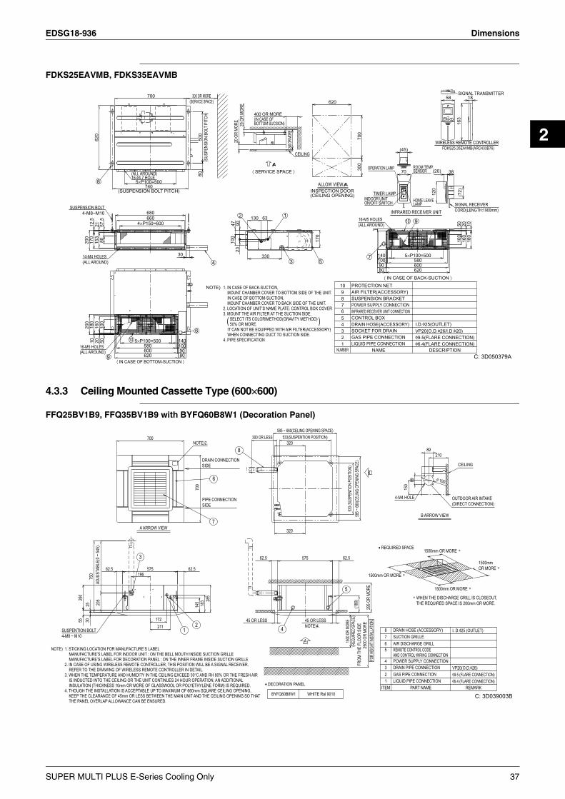
EDSG18-936 Dimensions
2
FDKS25EAVMB, FDKS35EAVMB
4.3.3 Ceiling Mounted Cassette Type (600×600)
FFQ25BV1B9, FFQ35BV1B9 with BYFQ60B8W1 (Decoration Panel)
SUSPENSION BOLT4-M8~M10
16-M5 HOLES(ALL AROUND)
200
200
14-M4 HOLES(ALL AROUND)
170
12.5
1018
0
8
620
153
2116
020
57.5
8010
050
9⟨ IN CASE OF BOTTOM-SUCTION ⟩
10
(ALL AROUND)16-φ4.7 HOLE
(SUSPENSION BOLT PITCH)
5×P100=500
4×P150=600
5×P100=500
580
620600
740
660680
700
1401009080
300 OR MORE(SERVICE SPACE)
6
6050
0(S
USPE
NSIO
N BO
LT P
ITCH
)
4
4710
020
OR
MORE
2
2390
20 O
R MO
RE
⟨ SERVICE SPACE ⟩
130
NOTE)
330
63
(IN CASE OFBOTTOM SUCSION)
400 OR MORE
3. MOUNT THE AIR FILTER AT THE SUCTION SIDE.
4. PIPE SPECIFICATION
2. LOCATION OF UNIT‘S NAME PLATE: CONTROL BOX COVER
1. IN CASE OF BACK-SUCTION,
(WHEN CONNECTING DUCT TO SUCTION SIDE.
MOUNT CHAMBER COVER TO BOTTOM SIDE OF THE UNIT.
MOUNT CHAMBER COVER TO BACK SIDE OF THE UNIT.
SELECT ITS COLORIMETHOD(GRAVITY METHOD)50% OR MORE.
IN CASE OF BOTTOM-SUCTION,
IT CAN NOT BE EQUIPPED WITH AIR FILTER(ACCESSORY)
1
3
240 OR
MORE
CEILING
ALLOW VIEW
5
170
INSPECTION DOOR(CEILING OPENING)
620
)
300
700
16-M5 HOLES(ALL AROUND)
7
NUMBER
OPERATION LAMP
INDOOR UNITON/OFF SWITCH
10
3
5
7
4
6
89
21
TIMER LAMP
8090
140100
POWER SUPPLY CONNECTION
GAS PIPE CONNECTIONSOCKET FOR DRAIN
CONTROL BOXINFRARED RECEIVER UNIT CONNECTION
AIR FILTER(ACCESSORY)
DRAIN HOSE(ACCESSORY)
SUSPENSION BRACKET
PROTECTION NET
LIQUID PIPE CONNECTIONNAME
⟨ IN CASE OF BACK-SUCTION ⟩
INFRARED RECEIVER UNIT
(45)
70
DAIKIN
10
5×P100=500
HOME LEAVELAMP
ROOM TEMP.SENSOR
9
580
620600
VP20(O.D.φ26/I.D.φ20)
φ6.4(FLARE CONNECTION)φ9.5(FLARE CONNECTION)
I.D.φ25(OUTLET)
DESCRIPTION
120
(20)
WIRELESS REMOTE CONTROLLERFDKS25,35EAVMB(ARC433B76)
58
38
DAIKIN
SIGNAL RECEIVERCORD(LENGTH:1900mm)
SIGNAL TRANSMITTER
100
50(7
2)16
316
020 10
180
18
30
C: 3D050379A
SUSPENTION BOLT4-M8 ~ M10
NOTE) 1. STICKING LOCATION FOR MANUFACTURE’S LABELMANUFACTURE’S LABEL FOR INDOOR UNIT : ON THE BELL MOUTH INSIDE SUCTION GRILLEMANUFACTURE’S LABEL FOR DECORATION PANEL : ON THE INNER FRAME INSIDE SUCTION GRILLE
2. IN CASE OF USING WIRELESS REMOTE CONTROLLER, THIS POSITION WILL BE A SIGNAL RECEIVER.REFER TO THE DRAWING OF WIRELESS REMOTE CONTROLLER IN DETAIL.
3. WHEN THE TEMPERATURE AND HUMIDITY IN THE CEILING EXCEED 30°C AND RH 80% OR THE FRESH AIRIS INDUCTED INTO THE CEILING OR THE UNIT CONTINUES 24 HOUR OPERATION, AN ADDITIONALINSULATION (THICKNESS 10mm OR MORE OF GLASSWOOL OR POLYETHYLENE FORM) IS REQUIRED.
4. THOUGH THE INSTALLATION IS ACCEPTABLE UP TO MAXIMUM OF 660mm SQUARE CEILING OPENING,KEEP THE CLEARANCE OF 45mm OR LESS BETWEEN THE MAIN UNIT AND THE CEILING OPENING SO THATTHE PANEL OVERLAP ALLOWANCE CAN BE ENSURED.
260
5525
3075
020
5AD
JUST
ABLE
(0 ~
545)
62.5196
A ARROW VIEW
575
700
172211
62.5
NOTE)2.
145
700
PIPE CONNECTIONSIDE
DRAIN CONNECTIONSIDE
183 28
5
45 OR LESS
300 OR LESS
62.5
• DECORATION PANEL
BYFQ60B8W1
585 ~ 660(CELING OPENING SPACE)533(SUSPENTION POSITION)
320
320
575
WHITE Ral 9010
A
45 OR LESSNOTE)4.
62.5
1500
OR
MORE
(REQ
UIRE
D SP
ACE)
533 (
SUSP
ENTIO
N PO
SITIO
N)(1
80)
585 ~
660(C
ELIN
G OP
ENIN
G SP
ACE)
FROM
THE
FLO
OR S
IDE
2500
OR
MORE
B
295 O
R MO
REFO
R HEIG
HT IN
STAL
LATIO
N
• REQUIRED SPACE
1500mm OR MORE ∗
ITEM
32
5
76
4
1
8
POWER SUPPLY CONNECTION
GAS PIPE CONNECTION
REMOTE CONTROL CODEAND CONTROL WIRING CONNECTION
DRAIN PIPE CONNECTION
SUCTION GRILLEAIR DISCHARGE GRILL
LIQUID PIPE CONNECTION
DRAIN HOSE (ACCESSORY)
4-M4 HOLE
PART NAME
150
89
B ARROW VIEW
1500mm OR MORE ∗
89
∗ WHEN THE DISCHARGE GRILL IS CLOSEOUT, THE REQUIRED SPACE IS 200mm OR MORE.
210
1500mm OR MORE ∗
φ 100
OUTDOOR AIR INTAKE(DIRECT CONNECTION)
φ9.5 (FLARE CONNECTION)φ6.4 (FLARE CONNECTION)
VP20(O.D.φ26)
I. D.φ25 (OUTLET)
CEILING
REMARK
C: 3D039003B
1500mmOR MORE ∗
4
5
3
12
7
6
8
SUPER MULTI PLUS E-Series Cooling Only 37

Dimensions EDSG18-936
FFQ50BV1B9, FFQ60BV1B9 with BYFQ60B8W1 (Decoration Panel)
BYFQ60B8W1 — Decoration Panel (Option) —
NOTE)
SUSPENTION BOLT4-M8~M10
3.WHEN THE TEMPERATURE AND HUMIDITY IN THE CEILING EXCEED 30°C AND RH 80% OR THE FRESH AIR
4.THOUGH THE INSTALLATION IS ACCEPTABLE UP TO MAXIMUM OF 660mm SQUARE CEILING OPENING,
2.IN CASE OF USING WIRELESS REMOTE CONTROLLER, THIS POSITION WILL BE A SIGNAL RECEIVER.
260
55
1.STICKING LOCATION FOR MANUFACTURE’S LABEL
REFER TO THE DRAWING OF WIRELESS REMOTE CONTROLLER IN DETAIL.
THE PANEL OVERLAP ALLOWANCE CAN BE ENSURED.KEEP THE CLEARANCE OF 45mm OR LESS BETWEEN THE MAIN UNIT AND THE CEILING OPENING SO THAT
MANUFACTURE’S LABEL FOR DECORATION PANEL :ON THE INNER FRAME INSIDE SUCTION GRILLEMANUFACTURE’S LABEL FOR INDOOR UNIT:ON THE BELL MOUTH INSIDE SUCTION GRILLE
IS INDUCTED INTO THE CEILING OR THE UNIT CONTINUES 24 HOUR OPERATION,AN ADDITIONALINSULATION (THICKNESS 10mm OR MORE OF GLASSWOOL OR POLYETHYLENE FORM) IS REQUIRED.
2530
750
ADJU
STAB
LE( 0
~ 545
)20
5
62.5196
3
A ARROW VIEW
575
700
172211
1
62.5
NOTE)2.
2
145
700
SIDEPIPE CONNECTION
SIDEDRAIN CONNECTION
183 28
5
7
6
8
45 OR LESS
300 OR LESS
62.5
• DECORATION PANEL
BYFQ60B8W1
585~660(CELING OPENING SPACE)
4
533 (SUSPENTION POSITION)320
320
575
WHITE Ral 9010
A
45 OR LESSNOTE)4.
62.5
5
1500
OR
MO
RE53
3 (SU
SPEN
TION
POSI
TION)
( REQ
UIRE
D SP
ACE)
( 180
)58
5~66
0(CE
LING
OPEN
ING
SPAC
E)FR
OM T
HE F
LOOR
SID
E25
00 O
R M
OR
E
B
295
OR M
ORE
FOR
HEIG
HT IN
STAL
LATIO
N
• REQUIRED SPACE
1500mm OR MORE ∗
ITEM
23
65
7
4
1
8
POWER SUPPLY CONNECTION
GAS PIPE CONNECTION
AND CONTROL WIRING CONNECTIONREMOTE CONTROL CODE
DRAIN PIPE CONNECTION
SUCTION GRILLEAIR DISCHARGE GRILL
LIQUID PIPE CONNECTION
DRAIN HOSE (ACCESSORY)
4-M4 HOLE
PAR TNAME
150
89
B ARROW VIEW
1500mm OR MORE ∗
89
∗ WHEN THE DISCHARGE GRILL IS CLOSEOUT,
THE REQUIRED SPACE IS 200mm OR MORE.
210
1500mm OR MORE ∗
φ100
OUTDOOR AIR INTAKE
φ12.7 (FLARE CONNECTION)φ6.4 (FLARE CONNECTION)
(DIRECT CONNECTION)
VP20 (O.D.φ26)
I. D.φ25 (OUTLET)
CEILING
REMARK
OR MORE OR MORE ∗∗1500mmOR MORE ∗
C: 3D039005B
62.5
2
A ARROW VIEW
575
700
62.5
105
700
143 24
5
3
62.5
A
575
15 DIM
ENSI
ON
BET
WEE
N
THE
BOTT
OM
SU
RFA
CE
OF
IND
OO
R U
NIT
AN
D
THE
SUR
FAC
E O
F C
EILI
NG
62.5
1
40 THIC
KNES
S( 1
40)
OF
PAN
EL S
PAC
ER25
5 O
R M
OR
E
ITEM
321
DECORATION PANELPANEL SPACER
INDOOR UNITNAME REMARK
3D041038
38 SUPER MULTI PLUS E-Series Cooling Only

EDSG18-936 Dimensions
2
BRC1C61 — Wired Remote Controller (Option) —
BRC7E531W — Wireless Remote Controller (Option for Cooling Only Type) —
REMOTE CONTROLLERREMOTE CONTROLLER
84
46
120 18CORD OUTLET HOLE
REMOTE CONTROLLER
17
120
117
CONDUITSTAPLE
17 THROUGH HOLE(φ12~φ16)
0~5
· REMOTE CONTROLLER DIMENSIONS
CONTROL BOX
17
17
· INSTALLATION METHOD
C: 3D028952
NOTE)1.REMOTE CONTROLLER CORD AND STAPLE ARE NOT ATTACHED.
VINYL CORD WITH SHEATH OR CABLE (INSULATED THICKNESS : 1mm OR MORE)
THEY ARE FIELD SUPPLIED PARTS.
· SPECIFICATIONS OF CORD
A EXPOSED BODY, EXPOSED CORD
38
EXPOSED BODY, EMBEDDED CORDC
23
0.75~1.25mm2
42
TYPE
LENGTH
B EXPOSED BODY, EMBEDDED CORD
28
SIZE
CONTROL BOXCONTROLLER ANDBETWEEN REMOTE)(
500mTOTAL
•REMOTE CONTROLLER HOLDER
•REMOTE CONTROLLER DIMENSIONS
REMOTE CONTROLLER
INSTALLATION PROCEDURE
REMOTE CONTROLLER(WIRELESS)
LIQUID CRYSTAL
157
<INSTALLATION TO WALL SURFACE>
HOLDER
62
TRANSMITTING PART
17.5
•RECEIVER DETAIL
•RECEIVER INSTALLATION PROCEDURE
RECEIVER
DRAIN PIPING SIDE REFRIGERANT PIPING SIDE
DECORATION PANEL(BYFQ60B8W1)
3D038937A
SUPER MULTI PLUS E-Series Cooling Only 39
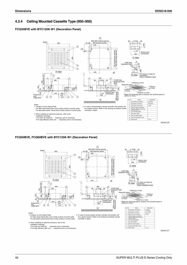
Dimensions EDSG18-936
4.3.4 Ceiling Mounted Cassette Type (950×950)
FCQ35BVE with BYC125K-W1 (Decoration Panel)
FCQ50BVE, FCQ60BVE with BYC125K-W1 (Decoration Panel)
Notes:1. Location of unit’s Name Plate
For Main body:Switch Box cover inside surface of suction grille.For decoration panel: Panel frame inside surface of suction grille.
2. When installing an optional accessory, refer to theinstallation drawings.• For fresh air intake kit……Inspection port is necessary.• For high efficiency filter unit……Inspection port is not necessary.
Suspensionbolt4-M8~M10
4023
010
3075
0Ad
justab
le(0~
550)
200
Note3.
55295
240
950
840
260270315
55
125
950
150 24
0
3. In case of using wireless remote controller, this position willbe a signal receiver. Refer to the drawing of wireless remotecontroller in detail.
300 or less
55
860~890 Ceiling opening
420
420
80
680 Suspension position
2 × 100=200840
C
A
35040
85
Branch ductconnection
55
150
(prepared hole)
B
12-M4 Hole
780
Susp
ensi
on p
ositi
on95
1000
or m
ore
860~
890
Cei
ling
open
ing
110
Requ
ired s
pace
165
*When the discharge grill is closeout, the required space is200mm or more.
*1500mmor more
Required space
(prepared hole)4-M4 Hole
80
φ75
2 × 100=200
*1500mm or more
350
40
60
*1500mm or more
80
80
For fresh air intake kitconnection(direct installation type)
85
160
Branch ductconnection
(165
)
*1500mmor more
3D049126
A viewB view
C view
8 5 4 1 2
3
6
7
910
2
3
8
5
7
4
6
1
910
Gas pipe connection
Power supply connection
Port for water supply
Remote control code and controlwiring connection
Corner decoration cover
Drain pipe connection
Drain hose
Air suction grille
Air discharge grille
Liquid pipe connection
O.D.32
VP25
φ9.5 flare
φ6.4 flare
Number Name Description
Number
2
3
8
7
6
4
5
1
910
Gas pipe connection
Power supply connection
Port for water supply
Remote control code and controlwiring connection
Corner decoration cover
Drain pipe connection
Drain hose
Air suction grille
Air discharge grille
Liquid pipe connectionName
O.D.32
VP25
φ6.4flareφ12.7flare
Description
3D049127
8 5
3
4 1
7
6
2
910
Notes:1. Location of unit’s Name Plate
For Main body:Switch Box cover inside surface of suction grille.For decoration panel:Panel frame inside surface of suction grille.
2. When installing an optional accessory, refer to theinstallation drawings.• For fresh air intake kit……Inspection port is necessary.• For high efficiency filter unit……Inspection port is not necessary.
3. In case of using wireless remote controller, this position willbe a signal receiver. Refer to the drawing of wireless remotecontroller in detail.
4-M8~M10
Suspensionbolt
230
4010
3075
0Ad
justab
le(0~
550)
200
Note3.
55295
240
950
840
260270315
55
950
125
150 24
0
300 or less
55
420
420
80
680 Suspension position860~890 Ceiling opening
2 × 100=200840
35040
85
Branch ductconnection
5512-M4 Hole
150
(prepared hole)
780
Susp
ensi
on p
ositi
on95
1000
or m
ore
860~
890
Cei
ling
open
ing
110
Requ
ired s
pace
165
*When the discharge grill is closeout, the required space is200mm or more.
*1500mmor more
Required space
(prepared hole)4-M4 Hole
80
φ75
2 × 100=200
*1500mm or more
350
40
60
*1500mm or more
80
80
For fresh air intake kitconnection(direct installation type)
85
160
Branch ductconnection
(165
)
*1500mmor more
B
C
A
A view
C view
B view
40 SUPER MULTI PLUS E-Series Cooling Only

EDSG18-936 Dimensions
2
FCQ71BVE with BYC125K-W1 (Decoration Panel)
BRC1C61 — Wired Remote Controller (Option) —
3D012312D
Notes:1. Location of unit’s Name Plate
For Main body: Switch Box Cover inside surface of suction grille.For decoration panel: Panel frame inside surface of suction grille.
2. When installing an optional accessory, refer to theinstallation drawings.
For fresh air intake kit……Inspection port is necessary. For high efficiency filter unit……Inspection port is not necessary.
3. In case of using wireless remote controller, this position willbe a signal receiver. Refer to the drawing of wireless remotecontroller in detail.
A view
Suspensionbolt4-M8~M10
230
4010
3075
0Ad
just
able
(0~5
50)
200
Note3.
55
5
295
240
950
840
260270315
5595
012
515
0 240
300 or less
55
860~890 Ceiling opening
420
420
80
680 Suspension position
2×100=200840
35040
85
Branch ductconnection
55
150
(prepared hole)12-M4 Hole
780
Sus
pens
ion
posi
tion
9510
00 or
mor
e11
0Re
quire
d spa
ce16
5
*When the discharge grill is closeout, the required space is200mm or more.
*1500mmor more
Required space
(prepared hole)4-M4 Hole
80
φ75
B view
2×100=200
C view
*1500mm or more
350
40
60
*1500mm or more
80
80
For fresh air intake kitconnection(direct installation type)
85
160
Branch ductconnection
(165
)
*1500mmor more
860~
890
Cei
ling
open
ing
8
3
4 1
9
6
7
2
10
Number
234
67
5
8
1
910
Gas pipe connection
Power supply connection
Port for water supply
Remote control code and control wiring connection
Corner decoration cover
Drain pipe connection
Drain hose
Air suction grilleAir discharge grille
Liquid pipe connectionName
VP25
φ9.5 flare φ15.9 flare
O.D.32
Description
B
C
A
REMOTE CONTROLLERREMOTE CONTROLLER
84
46
120 18CORD OUTLET HOLE
REMOTE CONTROLLER
17
120
117
CONDUITSTAPLE
17 THROUGH HOLE(φ12~φ16)
0~5
· REMOTE CONTROLLER DIMENSIONS
CONTROL BOX
17
17
· INSTALLATION METHOD
C: 3D028952
NOTE)1.REMOTE CONTROLLER CORD AND STAPLE ARE NOT ATTACHED.
VINYL CORD WITH SHEATH OR CABLE (INSULATED THICKNESS : 1mm OR MORE)
THEY ARE FIELD SUPPLIED PARTS.
· SPECIFICATIONS OF CORD
A EXPOSED BODY, EXPOSED CORD
38
EXPOSED BODY, EMBEDDED CORDC
23
0.75~1.25mm2
42
TYPE
LENGTH
B EXPOSED BODY, EMBEDDED CORD
28
SIZE
CONTROL BOXCONTROLLER ANDBETWEEN REMOTE)(
500mTOTAL
SUPER MULTI PLUS E-Series Cooling Only 41
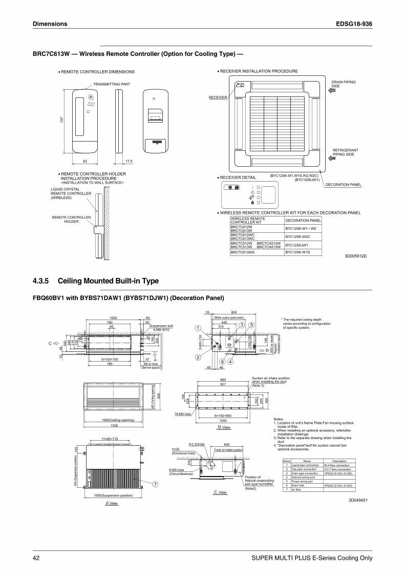
Dimensions EDSG18-936
BRC7C613W — Wireless Remote Controller (Option for Cooling Type) —
4.3.5 Ceiling Mounted Built-in Type
FBQ60BV1 with BYBS71DAW1 (BYBS71DJW1) (Decoration Panel)
• REMOTE CONTROLLER DIMENSIONS
• REMOTE CONTROLLER HOLDERINSTALLATION PROCEDURE
157
<INSTALLATION TO WALL SURFACE>
62
TRANSMITTING PART
17.5
RECEIVER
• WIRELESS REMOTE CONTROLLER KIT FOR EACH DECORATION PANEL
• RECEIVER DETAIL
• RECEIVER INSTALLATION PROCEDURE
CONTROLLER KITWIRELESS REMOTE
BRC7C613WSBRC7C513W
BRC7C613W
BRC7C512W
BRC7C612W
BRC7C613WCBRC7C612WC
BYC125KJW1
BYC125K-W2C
BYC125K-W1S
DECORATION PANEL
BYC125K-W1 • W2
DECORATION PANEL
SIDEDRAIN PIPING
REFRIGERANTPIPING SIDE
LIQUID CRYSTALREMOTE CONTROLLER (WIRELESS)
REMOTE CONTROLLERHOLDER
BRC7CA513WBRC7CA512W
(BYC125K-W1,W1S,W2,W2C)(BYC125KJW1)
3D005912D
1045
300
245
215
630 (
Susp
ensio
n pos
ition)
145
150 13
5
1050(Suspension position)
5×150=750
11×65=715
1060(Ceiling opening)
785
76065
1000
1100
View
(Service space)300 or more
50
57
60
67
Suspension bolt4-M8~M10
462 (
Ceilin
g ope
ning)
150
7
200
500
6-M5 hole(Circumference)
18-M5 hole
(Knockout hole)φ125
160
228
P.C.Dφ160
100
2
1
2×65
=130
25
45
6×150=900
595(Air suction panel center)
Fresh air intake position
315
46
View
1000
927950
6
440
View
600
4
800
3
Position ofNatural evaporatingpan type humidifier(Note2)
135
120
5
Suction air intake positionwhen installing the duct(Note 3)
150
250
195
300
350
or m
ore
Requ
ired
instal
lation
spac
e
3D049451
Number
2
7
43
65
1Gas pipe connection
Power wiring port
Air filterDrain hole
Drain pipe connectionInterunit wiring port
Liquid pipe connectionName
φ6.4 flare connectionφ12.7 flare connectionVP25(O.D.φ32 I.D.φ25)
VP25(O.D.φ32 I.D.φ25)
Description
Notes;1. Location of unit’s Name Plate:Fan housing surface
inside of filter.2. When installing an optional accessory, refertothe
installation drawings.3. Refer to the separate drawing when installing the
duct.4. "Decoration panel"and"Air suction canvas"are
optional accessories.
* The required ceiling depth varies according to configuration of specific system.
42 SUPER MULTI PLUS E-Series Cooling Only
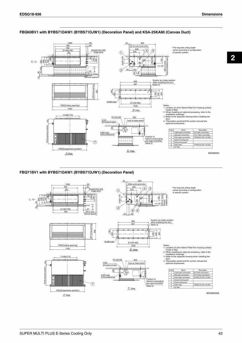
EDSG18-936 Dimensions
2
FBQ60BV1 with BYBS71DAW1 (BYBS71DJW1) (Decoration Panel) and KSA-25KA80 (Canvas Duct)
FBQ71BV1 with BYBS71DAW1 (BYBS71DJW1) (Decoration Panel)
4510
75~2
5530
024
521
563
0(Su
spen
sion p
ositio
n)14
515
0 135
1050(Suspension position)
11×65=715
5×150=750
785760
65
1000
1060(Ceiling opening)
1100
View
(Service space)300 or more
50
57
60
67
Suspension bolt4-M8~M10
150
462(C
eiling
open
ing)
7
200
500
6-M5 hole(Circumference)
(Knockout hole)
18-M5 hole
φ125
160
P.C.Dφ160
100
228
2
1
2×65
=130
25
45
Fresh air intake position
6×150=900
595 (Air suction panel center)
View
600
315
46
1000
927950
6
440
View
4
800
Position ofNatural evaporatingpan type humidifier(Note 2)
3
135
120
5
Suction air intake positionwhen installing the duct(Note 3)
150
250
300
195
425
or m
ore
Requ
ired i
nstal
lation
spac
e
Number
6
45
3
7
21
Gas pipe connection
Power wiring port
Air filterDrain hole
Drain pipe connectionInterunit wiring port
Liquid pipe connectionName
φ6.4 flare connectionφ12.7 flare connectionVP25(O.D.φ32 I.D.φ25)
VP25(O.D.φ32 I.D.φ25)
Description
3D049452
* The required ceiling depth varies according to configuration of specific system.
Notes;1. Location of unit’s Name Plate:Fan housing surface
inside of filter.2. When installing an optional accessory, refer to the
installation drawings.3. Refer to the separate drawing when installing the
duct.4. "Decoration panel"and"Air suction canvas"are
optional accessories.
* The required ceiling depth varies according to configuration of specific system.
Notes;1. Location of unit’s Name Plate:Fan housing surface
inside of filter.2. When installing an optional accessory, refer to the
installation drawings.3. Refer to the separate drawing when installing the
duct.4. "Decoration panel"and"Air suction canvas"are
optional accessories.
4510
300
245
215
630(
Susp
ensio
n pos
ition)
145
150 13
5
1050(Suspension position)
5×150=750
11×65=715
785
76065
1000
1060(Ceiling opening)1100
View
(Service space)300 or more
50
57
60
67
Suspension bolt4-M8~M10
462 (
Ceilin
g ope
ning)
150
7
200
500
6-M5 hole(Circumference)
18-M5 hole
(Knockout hole)φ125
160
228
P.C.Dφ160
100
2
1
2×65
=130
25
45
6×150=900
595(Air suction panel center)
Fresh air intake position
315
46
View
1000
927950
6
440
View
600
4
800
3
Position ofNatural evaporatingpan type humidifier(Note 2)
120
135
5
Suction air intake positionwhen installing the duct(Note 3)
150
250
195
300
350
or m
ore
Requ
ired
instal
lation
spac
e
Number
4
2
56
3
7
1Gas pipe connection
Power wiring port
Air filterDrain hole
Drain pipe connectionInterunit wiring port
Liquid pipe connectionName
φ9.5 flare connectionφ15.9 flare connectionVP25(O.D.φ32 I.D.φ25)
VP25(O.D.φ32 I.D.φ25)
Description
3D039435A
SUPER MULTI PLUS E-Series Cooling Only 43

Dimensions EDSG18-936
FBQ71BV1 with BYBS71DAW1 (BYBS71DJW1) (Decoration Panel) and KSA-25KA80 (Canvas Duct)
BRC1C61 — Wired Remote Controller (Option) —
* The required ceiling depth varies according to configuration of specific system.
Notes;1. Location of unit’s Name Plate:Fan housing surface
inside of filter.2. When installing an optional accessory, refer to the
installation drawings.3. Refer to the separate drawing when installing the
duct.4. "Decoration panel"and"Air suction canvas"are
optional accessories.
1045
300
75~2
5524
521
563
0 (Su
spen
sion p
ositio
n)14
515
0 135
1050(Suspension position)
5×150=750
11×65=715
1060(Ceiling opening)
785760
65
1000
1100
View
(Service space)
300 or more
50
57
60
67
Suspension bolt4-M8~M10
462 (
Ceilin
g ope
ning)
150
7
200
500
6-M5 hole(Circumference)
(Knockout hole)φ125
18-M5 hole
160
P.C.Dφ160
100
228
2
1
2×65
=130
25
45
Fresh air intake position
595(Air suction panel center)
View
6×150=900
600
315
46
1000
927950
6
440
View
4
800
Position ofNatural evaporatingpan type humidifier(Note 2)
3
120
135
5
Suction air intake positionwhen installing the duct(Note 3)
150
250
300
195
425
or m
ore
Requ
ired i
nstal
lation
spac
e
Number
6
4
7
32
5
1Gas pipe connection
Power wiring port
Air filterDrain hole
Drain pipe connectionInterunit wiring port
Liquid pipe connectionName
φ9.5 flare connectionφ15.9 flare connectionVP25(O.D.φ32 I.D.φ25)
VP25(O.D.φ32 I.D.φ25)
Description
3D039439A
REMOTE CONTROLLERREMOTE CONTROLLER
84
46
120 18CORD OUTLET HOLE
REMOTE CONTROLLER
17
120
117
CONDUITSTAPLE
17 THROUGH HOLE(φ12~φ16)
0~5
· REMOTE CONTROLLER DIMENSIONS
CONTROL BOX
17
17
· INSTALLATION METHOD
C: 3D028952
NOTE)1.REMOTE CONTROLLER CORD AND STAPLE ARE NOT ATTACHED.
VINYL CORD WITH SHEATH OR CABLE (INSULATED THICKNESS : 1mm OR MORE)
THEY ARE FIELD SUPPLIED PARTS.
· SPECIFICATIONS OF CORD
A EXPOSED BODY, EXPOSED CORD
38
EXPOSED BODY, EMBEDDED CORDC
23
0.75~1.25mm2
42
TYPE
LENGTH
B EXPOSED BODY, EMBEDDED CORD
28
SIZE
CONTROL BOXCONTROLLER ANDBETWEEN REMOTE)(
500mTOTAL
44 SUPER MULTI PLUS E-Series Cooling Only
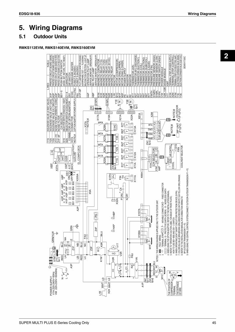
EDSG18-936 Wiring Diagrams
2
5. Wiring Diagrams5.1 Outdoor Units
RMKS112EVM, RMKS140EVM, RMKS160EVM
A3P
A4P
C4
X2M
A2P
L1R
X1M AIR
CONT
ROL
R1
HBP
(FRO
NT)
EL,C
OM
PO,B
OX
HAP
A1P
(BAC
K)
V3R
L
V1T
X37A
N
HEAT
S2S
S1NP
L
BP U
NIT
(F1)
(F2)
FAN
Y1S
X107
A
C4
X1M
X1M
A3P
C/H
SEL
ECTO
R
E
S1PH
LD
CF2
MS 3~
H6P
C2 W
WH
T
E1HC
R2
1X1
2A
NO
TE)8
BS5
V2RRED
NC
LB
U
LC
X5A
N=1
V
R1T
POW
ER S
UPP
LYV1
AVM
Z3F
12
N
BS1
N=6
H3P
YLW
OFF
-
V
BS4
DS1
X2A
K1M
-
A2P
CO
OL
R2T
HAP
+
+
BS2
C1
OU
TDO
OR
(F1)
(F2)
GR
N/Y
LW
V1R
K2R
ORG
H5P
BRN
BLU
R6T
Y3S
+
H1P
PS
THE
POSI
TION
OF
COMP
RESS
ORTE
RMIN
AL
X28A
H2P
Y1E
F4U
MS 3~
L1R
WH
T
THE E
NTRA
NCE
OF W
IRE
X37A
NO
TE)4
Z5C
N=4
X27A
6
P<
NA
RED
A
COOL
/HEA
T SE
LECT
OR
X22A
F1
BLU
Z7C
N=1
X2M
BS3
X17A
LE
S1S
X18A
TO BP
UNIT
M1F
1X1
3A
X26A
HBP
ON
Z6C
F1
Y2S
K3R
A4P
A1P
TO OUT
/D UNIT
NO
TE)9
X106
A
H4P
UBL
U
MS 3~
R7T
Z4F
X32A
F6U
t°
X25A
X1A
F1U
ORG
Z1C
NB
WHT
FIN TH
+
Z3C
N=1
K1R
Y3E
W
+
Z 2 F
X111
A
BLU
N=1
H7P
F2
K5R
Z2C
LA
C3
B
6
-
M
S1NP
H
X21A
MGR
Y
RED
M1C
P
M2F
H8P
+
X66A
RED
N
GR
NZ1
F
Z4C
N=1
K4R
L
X81A
X205
A
R4T
+
R5T
X11A
R3T
2.
: FIE
LD W
IRIN
G.
5. RE
FER
TO "O
PERA
TION
CAUT
ION
LABE
L "(O
N BA
CK O
F FRO
NT P
LATE
)HO
W TO
USE
BS1
~BS5
AND
DS1 •
2 SW
ITCH.
NOTE
S)1.
THIS
WIR
ING
DIAG
RAM
IS AP
PLIE
D ON
LY TO
THE
OUTD
OOR
UNIT.
6. W
HEN
OPER
ATIN
G,DO
N’T S
HORT
CIR
CUIT
FOR
PROT
ECTIO
N DE
VICE
.(S1P
H)
8. RE
FER
TO TH
E IN
STAL
LATIO
N MA
NUAL
,FOR
CONN
ECTIO
N W
IRIN
G TO
BP-O
UTDO
OR TR
ANSM
ISSI
ON F1
• F2.
9. W
HEN
USIN
G TH
E CE
NTRA
L CON
TROL
SYS
TEM,
CONN
ECT O
UTDO
OR-O
UTDO
OR TR
ANSM
ISSI
ON F1
• F2.
3.
: TER
MINA
L STR
IP
,
:
MOV
ABLE
CON
NECT
OR
: F
IXED
CON
NECT
OR: T
ERMI
NAL
:P
ROTE
CTIV
E EA
RTH
(SCR
EW)
:
NOIS
ELES
S EA
RTH
4. W
HEN
USIN
G TH
E OP
TION
ADAP
TOR,
REF
ER TO
THE
INST
ALLA
TION
MANU
AL.
7. CO
LORS
BLU
:BLU
E BR
N:BR
OWN
GRN:
GREE
N RE
D:RE
D W
HT:W
HITE
YLW:
YELL
OW O
RG:O
RANG
E.
R2T
SOLE
NOID
VAL
VE (4
WAY
VAL
VE)
R3T
DIO
DE
MO
DU
LE
SELE
CTOR
SW
ITCH
(FAN/
COOL
• HEA
T)S2
S
POW
ER M
OD
ULE
PILOT
LAMP
(SERV
ICE M
ONITO
R-OR
ANGE
)
R7T
Y1S
X2M
R6T
TER
MIN
AL S
TRIP
(CO
NTR
OL)
K2R
Y2S
THER
MIS
TOR
(M1C
DIS
CHAR
GE)
MAG
NET
IC R
ELAY
(Y2S
)
Y3S
R2
E1H
C
ED CI
RCUIT
BOAR
D (C/H
SELE
CTOR
)
C1~
4
MAG
NET
IC R
ELAY
THER
MIS
TOR
(FIN
)
Y1E
S1N
PH
L1R
HAP
MAG
NET
IC C
ON
TAC
TOR
MAG
NET
IC R
ELAY
(Y1S
)
NO
ISE
FILT
ER
V1R
SOLE
NOID
VAL
VE (U
/L C
IRCU
IT)
Z1C
~7C
MO
TOR
(FAN
) (LO
WER
)
S1S
BS1~
5
N-B
LUL-
RED
FIN
TH
K5R
PRES
SUR
E SW
ITC
H (H
IGH
)
R1
RES
ISTO
R
SELE
CTO
R SW
ITCH
(CO
OL/
HEAT
)D
IP S
WIT
CH
PUSH
BU
TTO
N S
WIT
CH
(MOD
E, S
ET, R
ETUR
N, TE
ST, R
ESET
)
X1M
V1T
MO
TOR
(CO
MPR
ESSO
R)
HBP
THER
MIS
TOR
(LIQ
UID
)TH
ERM
ISTO
R (S
UBC
OO
L)
ED CI
RCUIT
BOAR
D (NO
ISE FI
LTER
)
THER
MIS
TOR
(CO
IL)
MAG
NET
IC R
ELAY
(Y3S
)
POW
ER S
UPP
LY
SOLE
NO
ID V
ALVE
(HO
T G
AS)
PRES
SUR
E SE
NSO
R (H
IGH
)
THER
MIS
TOR
(SU
CTI
ON
1)
ELEC
TRON
IC EX
PANS
ION
VALV
E (MA
IN)
R5T
NOIS
E FI
LTER
(FER
RITE
CO
RE)
PRES
SUR
E SE
NSO
R (L
OW
)
REA
CTO
R
K3R
X1M
F1U
,F4U
INV.
PIL
OT
LAM
P(S
ERVI
CE M
ONIT
OR -
GREE
N)(A
1P)
F6U
CAP
ACIT
OR
THER
MIS
TOR
(AIR
)
R4T
MO
TOR
(FAN
) (U
PPER
)
DS1
THER
MIS
TOR
(SU
CTI
ON
2)
[H2P
]PREP
ARE,T
EST -
-----
FLIC
KERI
NGMA
LFUN
CTIO
N DE
TECT
ION
- LIG
HT U
P
A1P
K1R
C/H
SEL
ECTO
R
MAG
NET
IC R
ELAY
(E1H
C)
CR
ANKC
ASE
HEA
TER
H1P
~8P
PRIN
TED
CIRC
UIT B
OARD
(SER
VICE
)
Y3E
M1F
CO
NN
ECTO
R O
F O
PTIO
N A
DAP
TOR
PS
Z1F~
4F
OPE
RAT
ION
PIL
OT
LAM
P(S
ERVI
CE M
ONIT
OR -
GREE
N)(A
1P)
V2R
, V3R
TERM
INAL
STR
IP (P
OWER
SUP
PLY)
A2P
A3P
A4P
ELEC
TRON
IC EX
PANS
ION VA
LVE (
SUB C
OOL)
FUSE
(T 6
.3A/
250V
)C
ON
NEC
TOR
(OPT
ION
ADAP
TOR
POW
ER S
UPPL
Y)
K4R
RES
ISTO
RR
1T
S1N
PL
M2F
M1C
X37A
NO
TE)4
K1M
TERM
INAL
STRI
P (C/
H SE
LECT
OR) (A
4P)
FUSE
(T 5
.0A/
250V
)
S1PH
IGBT
PRIN
TED
CIRC
UIT
BOAR
D (M
AIN)
t°t°
t°t°
t°t°
t°
:220
-230
V~50
/60H
z:2
20-2
40V~
50H
z
3D05
1733
C
SUPER MULTI PLUS E-Series Cooling Only 45

Wiring Diagrams EDSG18-936
5.2 BP Units
BPMKS967B2B
BPMKS967B3B
ROOM B
ROOM AINDOOR
INDOOR
FIELD WIRING
3
3
2
2
1
1
PCB
OFF
X3M
X4M
3
2
3
2
1
1
32
4
1
TRANSMISSION
TRANSMISSION
DS2
CIRCUIT
CIRCUIT
H3PH4P
H2P
H5P
H1P
E1
LEDA
LED2
LED4LED3
LED1
(DLA)R1T
t°
(DGA)R2T
3.15AF2U
t°
(DLB)R3T
t°
(DGB)R4T
T201R
t°
(WHT)X90A
12
1 (WHT)
(RED)
(BLU)X22A
X20A
X21A
X6M
X1M
6
6
6
1
1
1
L2
F2
N2
L1
F1
N1
Y3E
Y2E
Y1E
M
M
M
L1N1
FOR TRANSMISSIONTO OUTDOOR (F1•F2)OR OTHER BP UNIT
ROOM A
ROOM B
BYPASS
TO OTHER BP UNIT
NL
POWER SUPPLY230V~50Hz
BLK
BLK
BLK
BLK
BLU
BLU
BLU
BLU
YLW
YLW
YLW
RED
BLURED
BLU
REDBLU
WHT
WHT
WHT
BRW
BRW
BRW
ORG
ORG
ORG
X20A~X22A, X90APCBF2U
: CONNECTOR: PRINTED CIRCUIT BOARD: FUSE
H1P~H5PR1T~R4TDS2
: PILOT LAMP: THERMISTOR: DIP SWITCH
: TRANSFORMAR: TERMINAL STRIP: MOTOR OPERATED VALVE COIL
T201RX1M, X3M, X4M, X6MY1E~Y3E
GRN/YLW
3D048565B
ROOM B
ROOM A
ROOM C
INDOOR
INDOOR
INDOOR
FIELD WIRING
3
3
3
2
2
2
1
1
1
PCB
OFF
X3M
X4M
X5M
2
3
2
2
3
3
1
1
1
34
21
TRANSMISSION
TRANSMISSION
TRANSMISSION
DS2
CIRCUIT
CIRCUIT
CIRCUIT
H2PH3PH4PH5P
H1P
E1
LEDA
LED2
LED4LED3
LED1
(DLA)R1T
t°
(DGA)R2T
3.15AF2U
t°
(DLB)R3T
t°
(DGB)R4T
T201R
t°
(DLC)R5T
t°
(DGC)R6T
t°
(WHT)X90A
12
1 (WHT)
(YLW)
(RED)
(BLU)X22A
X23A
X20A
X21A
X6M
X1M
6
6
6
6
1
1
1
1
L2
F2
N2
L1
F1
N1
Y4E
Y3E
Y2E
Y1E
M
M
M
M
L1N1
FOR TRANSMISSIONTO OUTDOOR (F1•F2)OR OTHER BP UNIT
ROOM C
ROOM B
ROOM A
BYPASS
TO OTHER BP UNIT
LN POWER SUPPLY
230V~50Hz
BLK
BLK
BLK
BLK
BLU
BLU
BLU
BLU
YLW
YLW
YLW
YLW
YLW
YLW
YLW
YLW
BLURED
RED
RED
BLU
BLU
REDBLU
WHT
WHT
WHT
WHT
BRW
BRW
BRW
BRW
ORG
ORG
ORG
ORG
GRN/YLW
X20A~X23A, X90APCBF2U
: CONNECTOR: PRINTED CIRCUIT BOARD: FUSE
H1P~H5PR1T~R6TDS2
: PILOT LAMP: THERMISTOR: DIP SWITCH
: TRANSFORMAR: TERMINAL STRIP: MOTOR OPERATED VALVE COIL
T201RX1M, X3M~X6MY1E~Y4E 3D048566A
46 SUPER MULTI PLUS E-Series Cooling Only

EDSG18-936 Wiring Diagrams
2
5.3 Indoor Units5.3.1 Wall Mounted Type
FTKS25DVM, FTKS35DVM
FTKS50FVM, FTKS60FVM, FTKS71FVM
WIRELESSREMOTE
CONTROLLER
PCB3
PCB4
INTELLIGENT EYESENSOR
LED3
LED2
H2P
H3P
LED1
H1P
S1W
R1T
t°
S27
S36
S26
PCB2
S35
S21
HA
SIGNALRECEIVER
PCB1
S29
S28
R2T
S32
t°
~RECTIFIER
1
M1S
M
S6
~
5
V1
TRANSMISSIONCIRCUIT
7
1
3.15A
S1
F1U
H2
H3
H1
INDOOR
M1F
FG
M
X1M
3
2
1
FIELD WIRING.
3
2
1
OUTDOOR
RE
D
OR
G
YLW
PN
K
BLU
WHT
BRN
RED
BLU
ORG
GRN
WHT
RED
/
BLK
YLW
FG : FRAME GROUNDF1U : FUSEH1P~H3P : PILOT LAMPM1F : FAN MOTORM1S : SWING MOTORPCB1~PCB4 : PRINTED CIRCUIT BOARDR1T, R2T : THERMISTOR.S1~S38 : CONNECTORS1W : OPERATION SWITCHX1M : TERMINAL STRIP
: PROTECTIVE EARTH
NOTE THAT OPERATION WILLRESTART AUTOMATICALLY IFTHE MAIN POWER SUPPLY ISTURNED OFF AND THEN BACKON AGAIN.
CAUTION
3D046453E
CONTROLLER
WIRELESS
REMOTE
PCB4
PCB3
PCB5
INTELLIGENT EYE
LED1
H1P
R1T
SENSOR
t
S37
S38
°
LED2
H2P
LED3
H3P
PCB2
S27
S36
S1W
RECEIVER
SIGNAL
S26
S35
S21
S29
S28
PCB1
R2T
S32
t°
~ RECTIFIER
1
RE
D
M1S
M
S6
OR
GY
LW
~
PN
K
5
BLU
1
TRANSMISSION
BR
NR
ED
CIRCUIT
M2S
S8
M
OR
GY
LW
7
1
3.15A
S1
PN
K
6
Fu
BLU
WHT
BRN
RED
BLU
ORG
H2
H3
H1
INDOOR
FG
M1F
M
GRN
R1T, R2T
M1S, M2SPCB1~ PCB5
WHT
RED
/
BLK
Fu
M1F
H1 ~ H3
S1 ~ S38
H1P ~ H3P
FG
YLW
X1MS1W
X1M
3
2
1
: PROTECTIVE EARTH
THE MAIN POWER SUPPLY IS
ON AGAIN.TURNED OFF AND THEN BACK
NOTE THAT OPERATION WILLRESTART AUTOMATICALLY IF
FIELD WIRING.
CAUTION
3
2
1
OUTDOOR
: FRAME GROUND: FUSE: HARNESS: PILOT LAMP: FAN MOTOR: SWING MOTOR: PRINTED CIRCUIT BOARD: THERMISTOR: CONNECTOR: OPERATION SWITCH: TERMINAL STRIP
3D038530S
SUPER MULTI PLUS E-Series Cooling Only 47

Wiring Diagrams EDSG18-936
FTKS50BVMA8
5.3.2 Duct Connected Type
FDKS25CAVMB, FDKS35CAVMB, FDKS50CVMB, FDKS60CVMB, FDKS25EAVMB, FDKS35EAVMB
CONTROLLER
WIRELESSREMOTE
PCB4
PCB3
PCB5
INTELLIGENT EYE
LED1
H1P
R1T
SENSOR
t°
S37
S38
LED2
H2P
LED3
H3P
PCB2
S27
S36
S1W
RECEIVERSIGNAL
S26
S35
S21
S29
S28
PCB1
R2T
S32
t°
~RECTIFIER
1
RE
D
M1S
M
S6
OR
GY
LW
~
PN
K
5
BLU
1
TRANSMISSION
BR
NR
ED
CIRCUIT
M2S
S8
M
OR
GY
LW
7
1
3.15A
S1
PN
K
6
Fu
BLU
WHT
BRN
RED
BLU
ORG
H2
H3
H1
INDOOR
M1F
FG
M
GRN
FG
Fu
H1~H3
H1P~H3P
M1F
M1S, M2SPCB1~PCB5
R1T, R2T
S1~S38
S1W
X1M
WHT
RED
/
BLK
YLW
X1M
3
2
1
: SWING MOTOR
: THERMISTOR
: PROTECTIVE EARTH
THE MAIN POWER SUPPLY IS
ON AGAIN.TURNED OFF AND THEN BACK
NOTE THAT OPERATION WILLRESTART AUTOMATICALLY IF
FIELD WIRING.
CAUTION
3
2
1
OUTDOOR
: FRAME GROUND
: FUSE
: HARNESS
: PILOT LAMP
: FAN MOTOR
: PRINTED CIRCUIT BOARD
: CONNECTOR
: OPERATION SWITCH
: TERMINAL STRIP
3D038065K
PCB2
RECEIVERSIGNAL
LED
H1P
CONTROLLERREMOTE
WIRELESS
LED
H2P
S1W
LED
H3P
2RTH1
R1T
t°
10
1S1
1
C1
BRN
F1U :
S26
2
PCB1
S32
R2T
t°
1
10
::
BRN
S21
1
FUSE
(
CAPACITOR(M1F)PROTECTIVE EARTH
TERMINAL FORCENTRALIZED CONTROL
indoor
31
S7
BLU
GRY
PPL
S1
)
RED
6
V1TR
1
M1F
~M
3
BLK
Q1M130°C
1
WHT
YLW
TRANSMISSIONCIRCUIT
C1
3.15AF1U
Q1M
M1F
V1TR S1W
X1M Z1C
H1P ~ H3P
R1T ~ R2T
PCB1 ~ PCB2
S1 ~ S32, RTH1
GND
H2
H3
H1
: FAN MOTOR: PRINTED CIRCUIT BOARD
: NOISE FILTER(FERRITE CORE)
: PHASE CONTROL CIRCUIT: TERMINAL BLOCK
: OPERATION SWITCH
: THERMAL PROTECTOR (M1F EMBEDDED): THERMISTOR
: PILOT LAMP
Z1CN=2
: CONNECTOR
GRN
GRN
WHT
/
/
BLK
RED
YLW
YLW
X1M
23
1
NOTE THAT OPERATION WILL
THE MAIN POWER SUPPLY ISTURNED OFF AND THEN BACK
RESTART AUTOMATICALLY IF
ON AGAIN.
CAUTION
FIELD WIRING.
23
1
outdoor
3D045012K
48 SUPER MULTI PLUS E-Series Cooling Only

EDSG18-936 Wiring Diagrams
2
5.3.3 Ceiling Mounted Cassette Type
FFQ25BV1B9, FFQ35BV1B9, FFQ50BV1B9, FFQ60BV1B9
A1P BS1PRINTED CIRCUIT BOARD PUSH BUTTON (ON/OFF)
:CONNECTER DISCRIMINATION COLOR FOR COMPONENTS.
C1 H1PCAPACITOR (M1F) LIGHT EMITTING DIODE
R3T :CONNECTER COLOR FOR COMPONENTS.
(ON-RED)F1U FUSE (F,5A,250V)
R2TR1T:CONNECTER COLOR FOR PRINTED CIRCUIT BOARD.t˚
HAP LIGHT EMITTING DIODE H2P LIGHT EMITTING DIODE
IN CASE OF SIMULTANEOUSYLW
(TIMER-GREEN)(SERVICE MONITOR GREEN)
t˚ t˚ GRNA1POPERATION SYSTEM
WHT
KPR MAGNETIC RELAY (M1P) H3P LIGHT EMITTING DIODE
INDOOR UNITINDOOR UNIT
M1F (FILTER SIGN-RED)MOTOR (INDOOR FAN)
YLW(SLAVE)(MASTER)
M1P
X24A NOTE)5X2M
MOTOR (DRAIN PUMP) H4P LIGHT EMITTING DIODE
X19ATO OUTDOOR X18A X17A WIREDF1UX2M NOTE)3X2M
(DEFROST-ORANGE)M1S MOTOR (SWING FLAP)
REMOTEBLK1UNIT X61A NOTE)3 CONTROLLER
Q1M THERMO SWITCH (M1F EMBEDDED)
F211
SS1 SELECTOR SWITCH
WHT2
(MAIN/SUB)R1T
T1R
THERMISTOR (AIR)
X10A F1 SS1X11A2 2
R2T THERMISTOR (COIL-1)
RED
SS2 SELECTOR SWITCH
3 P2 P2t˚33 R1T
(WIRELESS ADDRESS SET)R3T THERMISTOR (COIL-2)
X60A NOTE)3 P1X27A P1GRN/YLW
S1L CONNECTOR FOR OPTIONAL PARTSFLOAT SWITCH
X5A X1MH05VV-U4G2.5 C1
X24AT1R CONNECTOR (WIRELESSTRANSFORMER (220-240V/22V)
KPR
TO O
UT
DO
OR
UN
IT
REMOTE CONTROLLER)V1TR PHASE CONTROL CIRCUIT
A3P A4PA1PV1TR
X33AX1M
SS1
CONNECTORTERMINAL STRIP
H1P X20AREMOTE WH
T
YLW
X2M (ADAPTOR FOR WIRING)TERMINAL STRIP
BS1CONTROLLER H2P RED MSS2
RC X35A CONNECTORSIGNAL RECEIVER CIRCUIT
~H3P X25A Q1M
TC SIGNAL TRANSMISSION CIRCUIT (GROUP CONTROL ADAPTOR)
BLKX24A X2A H4P YLW M M1F
X40AWIRED REMOTE CONTROLLER CONNECTOR
NOTE)3 ~X1AX1A RC TC
R1T
YLW
(ON/OFF INPUT FROM OUTSIDE)THERMISTOR (AIR)
M1P
X60ASS1 CONNECTORSELECTOR SWITCH (MAIN/SUB)
RECEIVER/DISPLAY UNIT MSWX36A
X61A (INTERFACE ADAPTORWIRELESS REMOTE CONTROLLER(RECEIVER/DISPLAY UNIT) FOR SKY AIR SERIES)
M1SNOTE)3NOTES)
A3P PRINTED CIRCUIT BOARD
HAPX33A NOTE)3X40A NOTE)3 X35A
A4P PRINTED CIRCUIT BOARD
: TERMINAL1. X15A: CONNECTOR,S1L: FIELD WIRING
C1
2. IN CASE USING CENTRAL REMOTE CONTROLLER, CONNECT IT TO THE UNITIN ACCORDANCE WITH THE ATTACHED INSTALLATION MANUAL.
T1R
3. X24A, X33A, X35A, X40A, X60A AND X61A ARE CONNECTED WHEN THE OPTIONAL
X1M
ACCESSORIES ARE BEING USED.
X2MA1P
4. REMOTE CONTROLLER MODEL VARIES ACCORDING TO THE COMBINATIONSYSTEM, CONFIRM ENGINEERING MATERIALS AND CATALOGS, ETC. BEFORE CONNECTING.
5. GROUND THE SHIELD OF THE REMOTE CONTROLLER CORD TO THE INDOOR UNIT (IN CASE OF USING SHIELD WIRE).
CONTROL BOX
6. SYMBOLS SHOW AS FOLLOWS: RED:RED BLK:BLACK WHT:WHITE YLW:YELLOW PRP:PURPLE GRY:GRAY BLU:BLUE
3D064844
SUPER MULTI PLUS E-Series Cooling Only 49

Wiring Diagrams EDSG18-936
FCQ35BVE, FCQ50BVE, FCQ60BVE, FCQ71BVE
TO BP UNIT
H05VV-U4G2.5
X2M
2
3
1
GRN/YLW
WHT
BLK
REDX27A X60A
X61A
RC
X19A
R1T
t°
TC
X18A
R2T
t°
X25A
KPR
X10A
2.IN CASE USING CENTRAL REMOTE CONTROLLER, CONNECT IT TO THE UNITIN ACCORDANCE WITH THE ATTACHED INSTALLATION MANUAL.
3.X24A IS CONNECTED WHEN THE WIRELESS REMOTE CONTROLLER KIT IS BEING USED.4.REMOTE CONTROLLER MODEL VARIES ACCORDING TO THE COMBINATION
SYSTEM, CONFIRM ENGINEERING MATERIALS AND CATALOGS, ETC. BEFORE CONNECTING.5.GROUND THE SHIELD OF THE REMOTE CONTROLLER CORD TO THE INDOOR UNIT
(IN CASE OF USING SHIELD WIRE).
NOTES)1.
::FIELD WIRINGTERMINAL , : CONNECTOR
6.SYMBOLS SHOW AS FOLLOWS: RED:RED BLK:BLACK WHT:WHITE YLW:YELLOWPRP:PURPLE GRY:GRAY BLU:BLUE
7.CONFIRM THE METHOD OF SETTING THE SELECTOR SWITCH(SS1,SS2)BY INSTALLATION MANUAL AND ENGINEERING DATA, ETC.
X17A
R3T
YLW
YLWWHT
t°
YLW
YLW
X33A
T1Rt°
M1P
~M
:CONNECTER COLOUR FOR PRINTED CIRCUIT BOARD.:CONNECTER COLOUR FOR COMPONENTS.:CONNECTER DISCRIMINATION COLOUR FOR COMPONENTS.
X11A
X35A HAP
V1TR
NORM.
SS1
EMG.
NOTE)3
X36A
X15A
A1P
X20A
X24A
X5A
BLK
RED
X1M
GRN
NOTE)5
P2P1
YLW
C1
WH
T
S1L
MSW
M1F
M1S
SS1
~
P2
M
P1
NOTE)5
WIREDREMOTECONTROLLER
Q1M
R1T
NOTE)3X24A
X2M
A1P
T1R
C1
SWITCH BOX
RECEIVER/DISPLAY UNIT
A2P
X2A
A1P
SS2
SS1
X33A
SS1
X1A
3D048793
A3P
X1A
X60AX61A
H2PH3PH4P
H1P
X1M
X35A
BS1
C1
A2PA3P
S1LSS1
Q1M
X2MX1M
HAP
A1P
R1TR2TR3T
R1TSS1
M1PM1F
M1S
V1TR
KPR
T1R
WIRELESS REMOTE CONTROLLER
TCRC
(RECEIVER/DISPLAY UNIT)
WIRED REMOTE CONTROLLER
SELECTOR SWITCH(EMERGENCY)
PUSH BUTTON(ON/OFF)
SELECTOR SWITCH
SELECTOR SWITCH
CONNECTOR
CONNECTOR
CONNECTOR
(GROUP CONTROL ADAPTOR)
(ADAPTOR FOR WIRING)
LIGHT EMITTING DIODE
LIGHT EMITTING DIODE
LIGHT EMITTING DIODE
LIGHT EMITTING DIODE
(WIRELESS ADDRESS SET)
(ON-RED)
(DEFROST-ORANGE)
(FILTER SIGN-RED)
(INTERFACE ADAPTOR
(TIMER-GREEN)
(MAIN/SUB)
FOR SKY AIR SERIES)
FLOAT SWITCH
THERMO SWITCH(M1F EMBEDDED)
SELECTOR SWITCH(MAIN/SUB)
PHASE CONTROL CIRCUIT
SIGNAL TRANSMISSION CIRCUIT
TRANSFORMER(220-240V/22V)
SIGNAL RECEIVER CIRCUIT
(SERVICE MONITOR GREEN)
PRINTED CIRCUIT BOARD
LIGHT EMITTING DIODE
MAGNETIC RELAY(M1P)
PRINTED CIRCUIT BOARDPRINTED CIRCUIT BOARD
TERMINAL STRIPTERMINAL STRIP
MOTOR(SWING FLAP)MOTOR(DRAIN PUMP)MOTOR(INDOOR FAN)
THERMISTOR(AIR)
THERMISTOR(AIR)
THERMISTOR(COIL)
CAPACITOR(M1F)
THERMISTOR(LIQUID)
BS1
SS1
SS2
X33A
X35A
X60AX61A
H1P
H2P
H3P
H4P
CONNECTOR FOR OPTIONAL PARTS
50 SUPER MULTI PLUS E-Series Cooling Only

EDSG18-936 Wiring Diagrams
2
5.3.4 Ceiling Mounted Built-in Type
FBQ60BV1, FBQ71BV1
M
C1
Q1M
X1MX2M
A1P
HAP
M1FKPR
R1T
R3TSS1
R2T
S1LT1R
SS1R1T
K1R~4R
TCRC
M1P
WIRED REMOTE CONTROLLER
THERMO SWITCH(M1F EMBEDDED)
SELECTOR SWITCH(MAIN/SUB)
FLOAT SWITCH
SELECTOR SWITCH
SIGNAL RECEIVER CIRCUITSIGNAL TRANSMISSION CIRCUIT
TRANSFORMER(220-240V/22V)
(SERVICE MONITOR GREEN)LIGHT EMITTING DIODE
PRINTED CIRCUIT BOARD
MAGNETIC RELAY(M1P)MAGNETIC RELAY(M1F)
TERMINAL STRIPTERMINAL STRIP
(EMERGENCY)
MOTOR(DRAIN PUMP)MOTOR(INDOOR FAN)
CAPACITOR(M1F)
THERMISTOR(AIR)
THERMISTOR(AIR)
THERMISTOR(COIL)THERMISTOR(LIQUID)
X60AX61A
X35A
X33ACONNECTOR FOR OPTIONAL PARTS
CONNECTOR
CONNECTOR
CONNECTOR(GROUP CONTROL ADAPTOR)
(ADAPTOR FOR WIRING)
(INTERFACE ADAPTORFOR SKY AIR SERIES)
NOTES)
2.
1.
3. IN CASE USING CENTRAL REMOTE CONTROLLER, CONNECT ITTO THE UNIT IN ACCORDANCE WITH THE ATTACHED INSTALLATION MANUAL.
4. REMOTE CONTROLLER MODEL VARIES ACCORDING TO THE COMBINATION SYSTEM,CONFIRM ENGINEERING MATERIALS AND CATALOGS, ETC. BEFORE CONNECTING.
5. SYMBOLS SHOW AS FOLLOWS: RED:RED BLK:BLACK WHT:WHITE YLW:YELLOWGRN:GREEN GRY:GRAY BLU:BLUE ORG:ORANGE
6. CONFIRM THE METHOD OF SETTING THE SELECTOR SWITCH(SS1)BY INSTALLATION MANUAL AND ENGINEERING MATERIALS, ETC.
7. GROUND THE SHIELD OF THE REMOTE CONTROLLER CORD TO THE INDOOR UNIT(IN CASE OF USING SHIELD WIRE).
:FIELD WIRING
:TERMINAL , :CONNECTOR
X35AX33AX60AX61A
A1P
CONTROL BOX
SS1
C1
T1R
X2M
X1M
TO BP UNIT
H05VV-U4G2.5
X2M
2
3
1
WHT
BLK
REDX27A
INDOOR UNIT
X60A
X61A
RC TC
X25A
KPR
X33A
X10A
R1T
t°
WHT
X19A
T1R
X35A
t°
M1P~
R2T
X11A
t°
X18A
HAP
R3T
YLW
YLWWHT
t°
K3RK4R
K2RK1R
NORM.
X17A
SS1
EMG.
FLL
:CONNECTER COLOUR FOR PRINTED CIRCUIT BOARD.:CONNECTER COLOUR FOR COMPONENTS.:CONNECTER DISCRIMINATION COLOUR FOR COMPONENTS.
FHFM
FC
FL
A1P
X15A
X21A
X5A
ORG
GRYRED
BLKBLU
NOTE)7
X1MP2P1
S1L
M1F
Q1M
~
WIRED REMOTE CONTROLLER(OPTIONAL PARTS)
NOTE)7
WHT
YLW
SS1
C1
P2P1
GR
N/Y
LW
3D048487
R1T
M
SUPER MULTI PLUS E-Series Cooling Only 51

Piping Diagrams EDSG18-936
6. Piping Diagrams6.1 Outdoor Units
RMKS112EVM, RMKS140EVM, RMKS160EVM
SV
Oil
sepa
rato
r
SV
HPS
Capillarytube
High pressureswitch
Double pipeheat exchanger
Filter
Filter
SP
Solenoidvalve
Service port
ACCUMULATOR
Filter
Heat exchanger
Electronicexpansion valve
Four wayvalve
Filter
High pressuresensor
Capillarytube
Capillarytube
Filter
Electronicexpansion valve
Solenoidvalve
Compressor
Service portLow pressuresensor SP
Pressureregulating valve
Stop valve (With service port on field piping side φ7.9mm flare connection)3D052628
52 SUPER MULTI PLUS E-Series Cooling Only
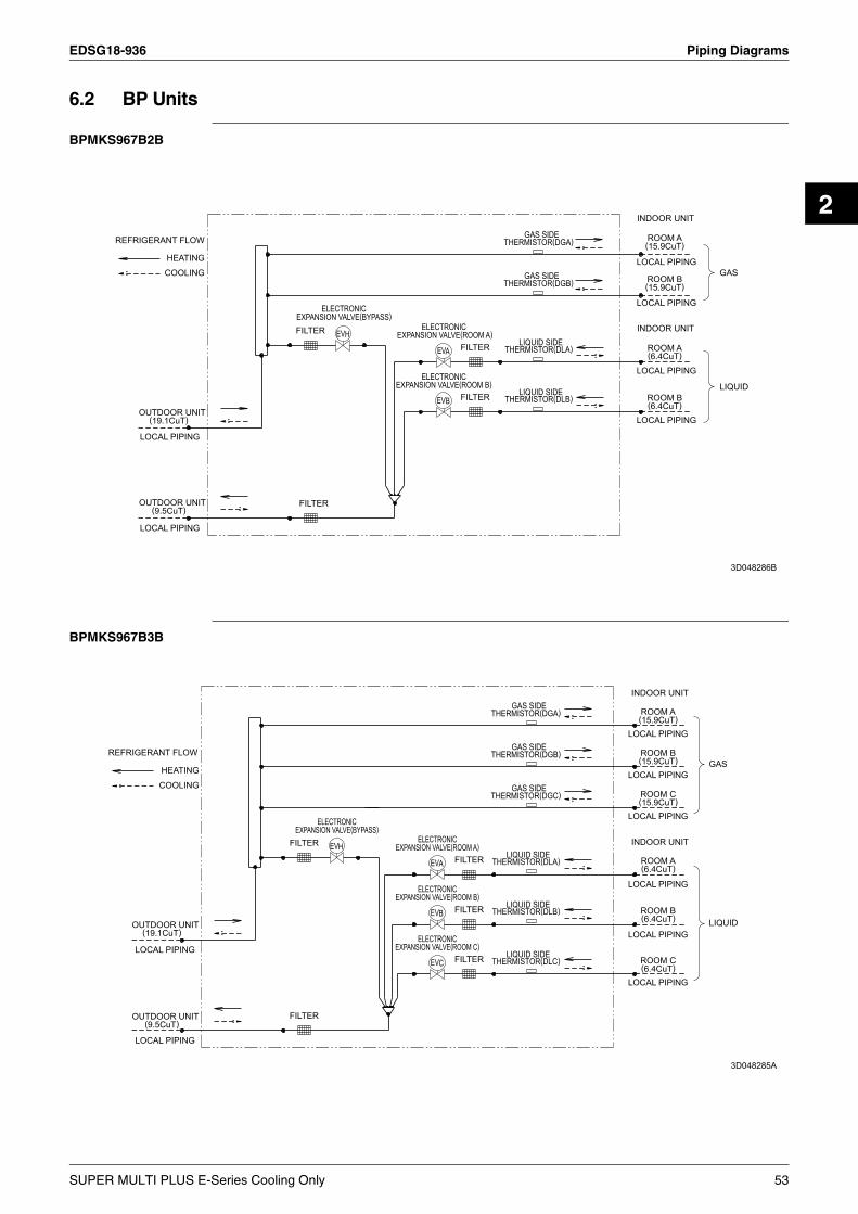
EDSG18-936 Piping Diagrams
2
6.2 BP Units
BPMKS967B2B
BPMKS967B3B
REFRIGERANT FLOW
OUTDOOR UNIT
LOCAL PIPING
LOCAL PIPING
LOCAL PIPING
LOCAL PIPING
LOCAL PIPING
LOCAL PIPING
OUTDOOR UNIT
(19.1CuT)
(9.5CuT)
HEATING
COOLING
FILTER
FILTER
EXPANSION VALVE(BYPASS)ELECTRONIC
EVH
EXPANSION VALVE(ROOM B)
EXPANSION VALVE(ROOM A)ELECTRONIC
ELECTRONIC
EV
EV
B
A FILTER
FILTER
THERMISTOR(DGA)
THERMISTOR(DGB)
THERMISTOR(DLA)
THERMISTOR(DLB)
GAS SIDE
GAS SIDE
LIQUID SIDE
LIQUID SIDE
INDOOR UNIT
(15.9CuT)
(15.9CuT)
INDOOR UNIT
ROOM A
ROOM B
(6.4CuT)
(6.4CuT)ROOM A
ROOM B
GAS
LIQUID
3D048286B
REFRIGERANT FLOW
OUTDOOR UNIT
OUTDOOR UNIT(9.5CuT)
(19.1CuT)
HEATING
COOLING
FILTER
FILTER
EXPANSION VALVE(BYPASS)ELECTRONIC
EVH
EXPANSION VALVE(ROOM C)
EXPANSION VALVE(ROOM B)
EXPANSION VALVE(ROOM A)
ELECTRONIC
ELECTRONIC
ELECTRONIC
EV
EV
EVA
B
C
FILTER
FILTER
FILTER
THERMISTOR(DGB)
THERMISTOR(DGA)
THERMISTOR(DGC)
THERMISTOR(DLA)
THERMISTOR(DLB)
THERMISTOR(DLC)
GAS SIDE
GAS SIDE
GAS SIDE
LIQUID SIDE
LIQUID SIDE
LIQUID SIDE
INDOOR UNIT
INDOOR UNIT
(15.9CuT)
(15.9CuT)
(15.9CuT)
(6.4CuT)
(6.4CuT)
(6.4CuT)
ROOM B
ROOM C
ROOM A
ROOM A
ROOM B
ROOM C
GAS
LIQUID
LOCAL PIPING
LOCAL PIPING
LOCAL PIPING
LOCAL PIPING
LOCAL PIPING
LOCAL PIPING
LOCAL PIPING
LOCAL PIPING
3D048285A
SUPER MULTI PLUS E-Series Cooling Only 53

Piping Diagrams EDSG18-936
6.3 Indoor Units6.3.1 Wall Mounted Type
FTKS25DVM, FTKS35DVM FTKS50FVM, FTKS60FVM
FIELD PIPING
FIELD PIPING
(9.5CuT)
(6.4CuT)
7.9C
uT
MUFFLER ASSY
CROSS FLOW FAN
FAN MOTOR
THERMISTORON HEAT EXCH.
INDOOR UNIT
M
6.4CuT
7.0CuT
9.5CuT
HEAT EXCHANGER
REFRIGERANT FLOW COOLING
6.4CuT
6.4CuT
4D050757D
CROSS FLOW FAN
COOLING
(12.7CuT)
INDOOR UNIT
REFRIGERANT FLOW
FIELD PIPING
M
(7.9CuT)
FIELD PIPING(12.7CuT)
FAN MOTOR
(6.4CuT)
THERMISTORON HEAT EXCH.
HEAT EXCHANGER
4D054932D
FTKS71FVM FTKS50BVMA8
(15.9CuT)
FIELD PIPING
FIELD PIPING
(6.4CuT)
CROSS FLOW FAN
FAN MOTOR
(7.9CuT)
INDOOR UNIT
(12.7CuT)
M
HEAT EXCHANGER
REFRIGERANT FLOW
ON HEAT EXCH.THERMISTOR
COOLING
4D050919H
FIELD PIPING
FIELD PIPING(12.7CuT)
(6.4CuT)
CROSS FLOW FAN
FAN MOTOR
(7.9CuT)
INDOOR UNIT
(12.7CuT)
M
HEAT EXCHANGER
REFRIGERANT FLOW
ON HEAT EXCH.THERMISTOR
HEATINGCOOLING
4D040081T
54 SUPER MULTI PLUS E-Series Cooling Only
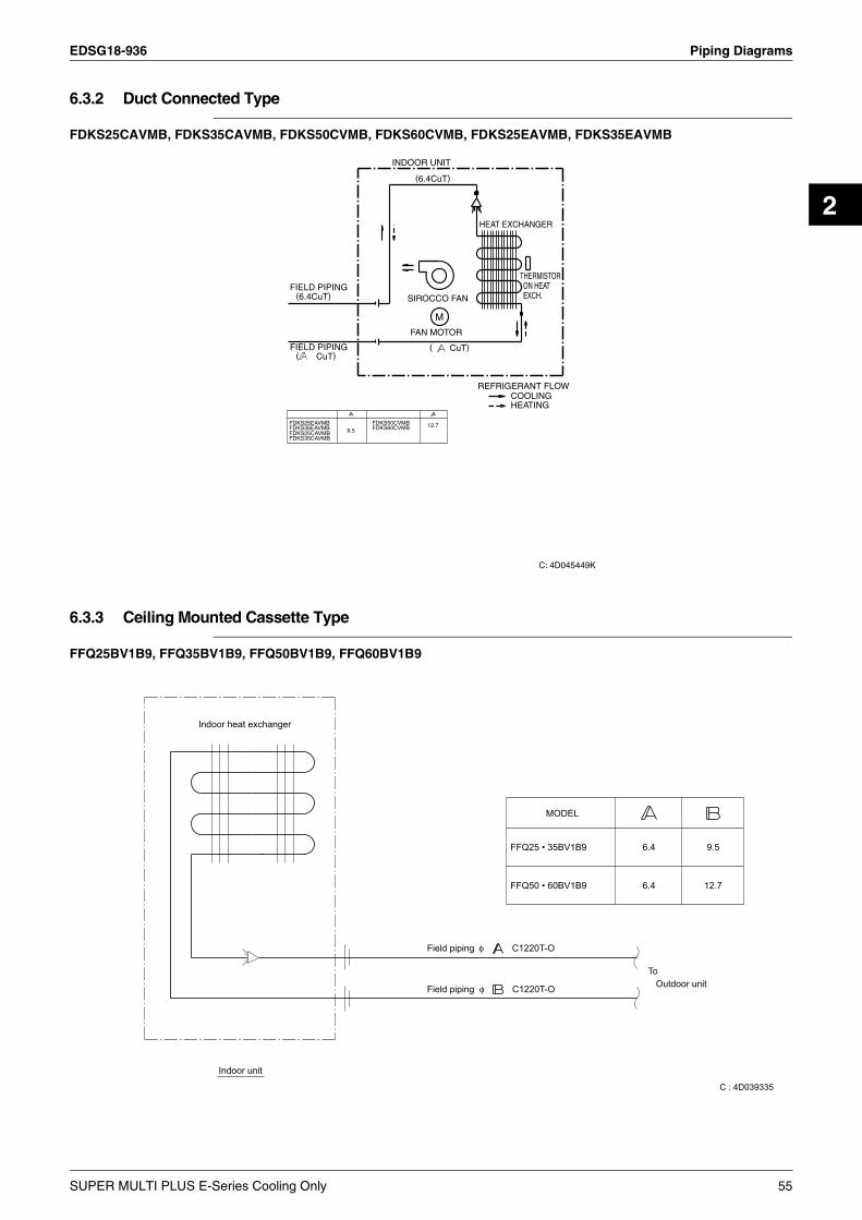
EDSG18-936 Piping Diagrams
2
6.3.2 Duct Connected Type
FDKS25CAVMB, FDKS35CAVMB, FDKS50CVMB, FDKS60CVMB, FDKS25EAVMB, FDKS35EAVMB
6.3.3 Ceiling Mounted Cassette Type
FFQ25BV1B9, FFQ35BV1B9, FFQ50BV1B9, FFQ60BV1B9
FIELD PIPING
FIELD PIPING( CuT)
(6.4CuT)
INDOOR UNIT
SIROCCO FAN
(6.4CuT)
( CuT)
FAN MOTOR
M
REFRIGERANT FLOW
HEAT EXCHANGER
COOLINGHEATING
THERMISTORON HEATEXCH.
12.79.5
FDKS35CAVMB
FDKS25EAVMB
FDKS25CAVMBFDKS35EAVMB
FDKS50CVMBFDKS60CVMB
C: 4D045449K
9.5
12.7
Outdoor unitTo
6.4
6.4
MODEL
FFQ50 • 60BV1B9
FFQ25 • 35BV1B9
Field piping φ C1220T-O
Field piping φ C1220T-O
Indoor unit
Indoor heat exchanger
C : 4D039335
SUPER MULTI PLUS E-Series Cooling Only 55

Piping Diagrams EDSG18-936
FCQ35BVE, FCQ50BVE, FCQ60BVE, FCQ71BVE
6.3.4 Ceiling Mounted Built-in Type
FBQ60BV1, FBQ71BV1
Indoor heat exchanger
FCQ35BVEFCQ50, 60BVEFCQ71BVE
Field piping
Field piping
C1220T-0
C1220T-0
6.46.49.5
φ
φ
12.715.9
9.5
ToOutdoor unit
MODEL
Indoor unit
C: 4D037995H
Indoor heat exchanger
FBQ60BV1FBQ71BV1
Field piping
Field piping
C1220T-0
C1220T-0
6.49.5
φ
φ
12.715.9
ToOutdoor unit
MODEL
Indoor unit
C: 4D037995H
56 SUPER MULTI PLUS E-Series Cooling Only

EDSG18-936 Capacity Tables
2
7. Capacity Tables7.1 Total Capacity7.1.1 RMKS112EVM
[Cooling Capacity]
Combination(%)
OutdoorAir Temp.
°CDB
Indoor Air Temp.:°CWB14°C 16°C 18°C 19°C 22°C 24°C
TC PI TC PI TC PI TC PI TC PI TC PIkW kW kW kW kW kW kW kW kW kW kW kW
130%
10 12.61 2.23 13.99 2.22 15.02 2.21 15.54 2.21 17.16 2.20 18.27 2.20 14 12.38 2.39 13.72 2.39 14.71 2.40 15.22 2.40 16.79 2.40 17.86 2.40 18 12.12 2.59 13.41 2.60 14.37 2.61 14.87 2.61 16.39 2.63 17.44 2.64 20 11.98 2.69 13.25 2.71 14.19 2.72 14.68 2.73 16.18 2.75 17.21 2.76 23 11.76 2.87 12.99 2.89 13.91 2.91 14.39 2.92 15.85 2.95 16.86 2.97 27 11.44 3.12 12.63 3.15 13.52 3.18 13.98 3.19 15.39 3.23 16.36 3.26 31 11.09 3.41 12.23 3.45 13.09 3.48 13.54 3.49 14.90 3.54 15.84 3.58 35 10.72 3.72 11.81 3.77 12.64 3.80 13.06 3.82 14.38 3.88 15.28 3.92 39 10.31 4.06 11.35 4.11 12.15 4.16 12.56 4.18 13.83 4.25 14.70 4.29 43 9.88 4.42 10.87 4.49 11.63 4.54 12.03 4.56 13.25 4.64 14.08 4.69 46 9.04 4.33 9.87 4.33 10.50 4.33 10.83 4.33 11.83 4.33 12.51 4.33
120%
10 12.46 2.17 13.79 2.16 14.82 2.15 15.33 2.15 16.94 2.14 18.05 2.13 14 12.23 2.33 13.51 2.33 14.50 2.33 15.01 2.33 16.57 2.34 17.64 2.34 18 11.97 2.52 13.20 2.53 14.17 2.54 14.66 2.55 16.17 2.56 17.21 2.57 20 11.83 2.63 13.04 2.64 13.99 2.66 14.47 2.66 15.96 2.68 16.98 2.70 23 11.61 2.80 12.78 2.82 13.71 2.84 14.18 2.85 15.63 2.88 16.63 2.90 27 11.29 3.06 12.42 3.09 13.31 3.11 13.77 3.12 15.17 3.16 16.14 3.19 31 10.94 3.34 12.03 3.37 12.89 3.40 13.33 3.42 14.68 3.47 15.62 3.50 35 10.57 3.64 11.61 3.69 12.44 3.73 12.86 3.74 14.17 3.80 15.06 3.84 39 10.17 3.98 11.16 4.03 11.96 4.07 12.36 4.10 13.62 4.16 14.49 4.21 43 9.74 4.34 10.68 4.40 11.44 4.45 11.83 4.47 13.04 4.55 13.87 4.60 46 8.92 4.33 9.74 4.33 10.37 4.33 10.69 4.33 11.68 4.33 12.36 4.33
110%
10 11.86 2.04 13.14 2.03 14.14 2.02 14.64 2.02 16.21 2.01 17.29 2.00 14 11.64 2.20 12.88 2.20 13.85 2.20 14.34 2.20 15.86 2.20 16.90 2.20 18 11.40 2.39 12.60 2.40 13.53 2.40 14.01 2.41 15.48 2.42 16.50 2.42 20 11.27 2.49 12.44 2.50 13.37 2.51 13.83 2.52 15.28 2.53 16.28 2.54 23 11.06 2.66 12.20 2.68 13.11 2.69 13.56 2.70 14.98 2.72 15.95 2.74 27 10.76 2.90 11.86 2.93 12.73 2.95 13.17 2.96 14.54 2.99 15.49 3.02 31 10.44 3.18 11.50 3.21 12.34 3.24 12.76 3.25 14.08 3.29 14.99 3.32 35 10.09 3.47 11.10 3.51 11.91 3.55 12.32 3.56 13.60 3.61 14.47 3.65 39 9.71 3.80 10.68 3.85 11.46 3.88 11.85 3.90 13.08 3.96 13.93 4.00 43 9.31 4.15 10.23 4.20 10.98 4.24 11.36 4.27 12.53 4.33 13.35 4.38 46 8.81 4.33 9.62 4.33 10.24 4.33 10.56 4.33 11.54 4.33 12.20 4.33
100%
10 10.54 1.81 11.79 1.80 12.71 1.79 13.18 1.78 14.64 1.77 15.64 1.75 14 10.36 1.96 11.57 1.95 12.47 1.95 12.93 1.95 14.34 1.94 15.31 1.94 18 10.16 2.13 11.33 2.13 12.20 2.13 12.65 2.13 14.02 2.14 14.96 2.14 20 10.06 2.22 11.21 2.23 12.06 2.24 12.50 2.24 13.85 2.24 14.78 2.25 23 9.89 2.38 11.00 2.39 11.84 2.40 12.27 2.40 13.59 2.42 14.49 2.43 27 9.64 2.60 10.71 2.62 11.52 2.64 11.93 2.65 13.21 2.67 14.09 2.68 31 9.37 2.85 10.40 2.88 11.18 2.90 11.58 2.91 12.82 2.94 13.67 2.96 35 9.07 3.13 10.06 3.16 10.82 3.19 11.20 3.20 12.39 3.24 13.22 3.26 39 8.75 3.43 9.70 3.47 10.42 3.50 10.80 3.51 11.95 3.56 12.74 3.59 43 8.41 3.75 9.31 3.80 10.01 3.83 10.36 3.85 11.47 3.90 12.24 3.94 46 8.13 4.01 9.00 4.06 9.68 4.10 10.02 4.12 11.10 4.18 11.84 4.21
90%
10 9.55 1.54 10.65 1.52 11.47 1.51 11.89 1.50 13.19 1.48 14.09 1.46 14 9.38 1.68 10.45 1.67 11.25 1.66 11.65 1.65 12.92 1.64 13.79 1.63 18 9.20 1.84 10.22 1.83 11.00 1.83 11.40 1.83 12.63 1.82 13.47 1.82 20 9.10 1.93 10.11 1.93 10.87 1.93 11.26 1.92 12.47 1.92 13.30 1.92 23 8.94 2.07 9.92 2.08 10.67 2.08 11.05 2.08 12.23 2.08 13.04 2.09 27 8.71 2.29 9.65 2.30 10.38 2.31 10.75 2.31 11.89 2.32 12.68 2.33 31 8.46 2.53 9.37 2.54 10.07 2.56 10.42 2.56 11.53 2.58 12.30 2.59 35 8.19 2.79 9.06 2.81 9.73 2.83 10.08 2.84 11.15 2.86 11.89 2.88 39 7.89 3.08 8.73 3.10 9.38 3.13 9.72 3.14 10.75 3.17 11.46 3.19 43 7.58 3.39 8.38 3.42 9.01 3.44 9.33 3.46 10.32 3.50 11.01 3.52 46 7.33 3.63 8.10 3.67 8.71 3.70 9.02 3.71 9.99 3.76 10.66 3.79
SUPER MULTI PLUS E-Series Cooling Only 57

Capacity Tables EDSG18-936
80%
10 8.50 1.29 9.46 1.27 10.19 1.25 10.57 1.24 11.72 1.21 12.52 1.19 14 8.35 1.42 9.28 1.40 9.99 1.39 10.35 1.38 11.48 1.36 12.26 1.34 18 8.18 1.56 9.08 1.55 9.77 1.54 10.13 1.54 11.22 1.52 11.98 1.52 20 8.09 1.65 8.98 1.64 9.66 1.63 10.01 1.63 11.08 1.62 11.83 1.61 23 7.95 1.78 8.81 1.77 9.47 1.77 9.82 1.77 10.87 1.77 11.60 1.76 27 7.74 1.98 8.57 1.98 9.22 1.98 9.55 1.98 10.57 1.98 11.28 1.98 31 7.52 2.20 8.32 2.21 8.94 2.21 9.26 2.22 10.25 2.22 10.94 2.23 35 7.28 2.45 8.05 2.46 8.65 2.47 8.96 2.47 9.92 2.49 10.58 2.50 39 7.02 2.72 7.76 2.73 8.34 2.75 8.64 2.75 9.56 2.78 10.20 2.79 43 6.74 3.01 7.45 3.03 8.01 3.05 8.30 3.06 9.19 3.08 9.80 3.10 46 6.52 3.25 7.21 3.27 7.75 3.29 8.03 3.30 8.89 3.33 9.49 3.35
70%
10 7.39 1.08 8.23 1.05 8.88 1.03 9.21 1.02 10.23 0.99 10.94 0.97 14 7.26 1.18 8.07 1.16 8.71 1.14 9.03 1.13 10.03 1.11 10.72 1.09 18 7.12 1.31 7.91 1.29 8.52 1.28 8.83 1.27 9.81 1.25 10.48 1.24 20 7.04 1.38 7.82 1.36 8.42 1.35 8.73 1.35 9.69 1.34 10.35 1.33 23 6.92 1.50 7.68 1.49 8.27 1.48 8.57 1.48 9.51 1.47 10.16 1.46 27 6.75 1.67 7.48 1.67 8.05 1.67 8.34 1.67 9.25 1.66 9.88 1.66 31 6.56 1.87 7.26 1.88 7.82 1.88 8.10 1.88 8.98 1.88 9.59 1.88 35 6.35 2.10 7.03 2.10 7.56 2.11 7.84 2.11 8.69 2.12 9.28 2.12 39 6.13 2.35 6.78 2.36 7.30 2.36 7.56 2.37 8.39 2.38 8.96 2.39 43 5.89 2.62 6.51 2.63 7.01 2.64 7.27 2.65 8.07 2.66 8.62 2.68 46 5.70 2.84 6.30 2.85 6.79 2.87 7.04 2.87 7.81 2.89 8.35 2.91
60%
10 6.22 0.89 6.95 0.87 7.52 0.85 7.81 0.84 8.72 0.81 9.35 0.79 14 6.12 0.97 6.83 0.95 7.39 0.93 7.68 0.93 8.56 0.90 9.17 0.89 18 6.01 1.07 6.70 1.05 7.25 1.04 7.52 1.04 8.38 1.02 8.98 1.01 20 5.95 1.13 6.63 1.11 7.17 1.10 7.44 1.10 8.29 1.08 8.88 1.07 23 5.86 1.23 6.52 1.22 7.05 1.21 7.31 1.20 8.15 1.19 8.72 1.19 27 5.72 1.38 6.36 1.37 6.87 1.37 7.13 1.36 7.94 1.36 8.50 1.35 31 5.57 1.55 6.19 1.55 6.68 1.54 6.93 1.54 7.72 1.54 8.26 1.54 35 5.40 1.74 6.00 1.74 6.48 1.75 6.72 1.75 7.48 1.75 8.01 1.75 39 5.22 1.96 5.79 1.97 6.26 1.97 6.49 1.97 7.23 1.98 7.74 1.99 43 5.02 2.20 5.58 2.21 6.02 2.22 6.25 2.22 6.96 2.23 7.45 2.24 46 4.87 2.39 5.40 2.41 5.83 2.42 6.06 2.42 6.75 2.44 7.23 2.45
50%
10 4.98 0.73 5.63 0.71 6.13 0.69 6.39 0.68 7.19 0.66 7.74 0.65 14 4.93 0.78 5.55 0.76 6.05 0.75 6.30 0.74 7.07 0.73 7.61 0.71 18 4.86 0.85 5.47 0.84 5.95 0.83 6.19 0.82 6.95 0.81 7.48 0.80 20 4.82 0.89 5.42 0.88 5.89 0.87 6.13 0.87 6.88 0.86 7.40 0.85 23 4.75 0.97 5.34 0.96 5.81 0.95 6.04 0.95 6.78 0.94 7.29 0.94 27 4.66 1.09 5.23 1.08 5.68 1.08 5.91 1.08 6.62 1.07 7.12 1.07 31 4.55 1.22 5.10 1.22 5.54 1.22 5.76 1.22 6.46 1.22 6.94 1.22 35 4.43 1.38 4.96 1.38 5.38 1.38 5.60 1.38 6.27 1.39 6.74 1.39 39 4.29 1.56 4.80 1.56 5.22 1.57 5.42 1.57 6.08 1.58 6.53 1.58 43 4.14 1.76 4.63 1.76 5.03 1.77 5.23 1.77 5.87 1.79 6.30 1.80 46 4.02 1.92 4.50 1.93 4.88 1.94 5.08 1.94 5.70 1.96 6.12 1.97
Symbols NOTE:TC : Total capacity (kW) 1. This table shows outdoor unit cooling capacity and power input.
2. is specified point.3. PI of indoor units is not included in the table.
3D052905
PI : Power input (kW)
Combination(%)
OutdoorAir Temp.
°CDB
Indoor Air Temp.:°CWB14°C 16°C 18°C 19°C 22°C 24°C
TC PI TC PI TC PI TC PI TC PI TC PIkW kW kW kW kW kW kW kW kW kW kW kW
58 SUPER MULTI PLUS E-Series Cooling Only

EDSG18-936 Capacity Tables
2
7.1.2 RMKS140EVM
[Cooling Capacity]
Combination(%)
OutdoorAir Temp.
°CDB
Indoor Air Temp.:°CWB14°C 16°C 18°C 19°C 22°C 24°C
TC PI TC PI TC PI TC PI TC PI TC PIkW kW kW kW kW kW kW kW kW kW kW kW
130%
10 14.84 2.78 16.49 2.79 17.75 2.79 18.37 2.80 20.25 2.81 21.56 2.82 14 14.55 2.98 16.14 2.99 17.36 3.01 17.96 3.02 19.79 3.05 21.05 3.07 18 14.23 3.20 15.76 3.23 16.94 3.26 17.52 3.27 19.29 3.31 20.51 3.35 20 14.06 3.32 15.56 3.36 16.72 3.39 17.29 3.41 19.03 3.46 20.23 3.50 23 13.78 3.53 15.24 3.57 16.37 3.61 16.93 3.63 18.62 3.69 19.79 3.73 27 13.39 3.82 14.78 3.88 15.87 3.93 16.41 3.95 18.04 4.03 19.18 4.08 31 12.96 4.15 14.29 4.22 15.34 4.28 15.86 4.30 17.43 4.39 18.52 4.45 35 12.49 4.51 13.77 4.59 14.77 4.65 15.27 4.69 16.78 4.78 17.83 4.85 39 11.99 4.90 13.20 4.99 14.16 5.06 14.64 5.10 16.73 5.13 17.65 5.13 43 11.47 5.13 12.53 5.13 13.35 5.13 13.75 5.13 14.95 5.13 15.78 5.13 46 8.69 4.10 9.52 4.10 10.16 4.10 10.49 4.10 11.42 4.10 12.17 4.10
120%
10 14.57 2.74 16.21 2.74 17.45 2.74 18.05 2.75 19.90 2.76 21.20 2.77 14 14.30 2.92 15.88 2.94 17.07 2.95 17.66 2.96 19.46 2.99 20.71 3.01 18 14.00 3.14 15.52 3.17 16.67 3.20 17.24 3.21 18.98 3.25 20.20 3.28 20 13.83 3.26 15.32 3.30 16.46 3.33 17.02 3.34 18.73 3.39 19.93 3.43 23 13.57 3.46 15.02 3.50 16.12 3.54 16.67 3.56 18.34 3.62 19.50 3.66 27 13.19 3.75 14.58 3.81 15.65 3.85 16.17 3.87 17.79 3.95 18.91 4.00 31 12.78 4.07 14.11 4.14 15.13 4.19 15.64 4.22 17.20 4.30 18.28 4.36 35 12.33 4.43 13.60 4.50 14.58 4.57 15.07 4.60 16.57 4.69 17.61 4.76 39 11.84 4.81 13.05 4.90 14.00 4.97 14.46 5.00 15.90 5.11 17.43 5.13 43 11.33 5.13 12.37 5.13 13.18 5.13 13.58 5.13 14.77 5.13 15.59 5.13 46 8.58 4.10 9.40 4.10 10.03 4.10 10.36 4.10 11.27 4.10 12.02 4.10
110%
10 14.29 2.68 15.93 2.68 17.17 2.68 17.76 2.68 19.61 2.69 20.90 2.70 14 14.03 2.86 15.61 2.87 16.81 2.89 17.39 2.89 19.18 2.92 20.43 2.94 18 13.74 3.07 15.26 3.10 16.42 3.12 16.98 3.14 18.72 3.17 19.93 3.20 20 13.58 3.19 15.08 3.23 16.22 3.25 16.77 3.27 18.47 3.31 19.67 3.35 23 13.33 3.39 14.78 3.43 15.89 3.46 16.43 3.48 18.09 3.54 19.26 3.57 27 12.97 3.67 14.36 3.73 15.43 3.77 15.94 3.79 17.55 3.86 18.68 3.91 31 12.57 3.99 13.90 4.06 14.93 4.11 15.43 4.13 16.98 4.21 18.06 4.27 35 12.13 4.34 13.40 4.42 14.39 4.48 14.87 4.51 16.37 4.60 17.41 4.66 39 11.66 4.73 12.87 4.81 13.82 4.88 14.28 4.91 15.72 5.01 16.73 5.08 43 11.19 5.13 12.22 5.13 13.02 5.13 13.41 5.13 14.58 5.13 15.39 5.13 46 8.47 4.10 9.28 4.10 9.90 4.10 10.22 4.10 11.13 4.10 11.86 4.10
100%
10 13.35 2.45 14.93 2.44 16.14 2.44 16.70 2.44 18.47 2.45 19.72 2.45 14 13.11 2.62 14.64 2.63 15.80 2.64 16.35 2.65 18.07 2.66 19.28 2.68 18 12.83 2.83 14.31 2.85 15.44 2.87 15.97 2.87 17.63 2.90 18.80 2.93 20 12.69 2.94 14.14 2.97 15.25 2.99 15.77 3.00 17.40 3.04 18.56 3.06 23 12.45 3.12 13.86 3.16 14.94 3.19 15.45 3.20 17.04 3.25 18.17 3.28 27 12.12 3.39 13.46 3.44 14.51 3.48 15.00 3.50 16.54 3.55 17.63 3.59 31 11.74 3.69 13.04 3.75 14.04 3.80 14.52 3.82 16.00 3.89 17.05 3.94 35 11.34 4.02 12.58 4.09 13.54 4.14 14.00 4.17 15.43 4.25 16.49 4.30 39 10.91 4.39 12.08 4.46 13.01 4.52 13.45 4.55 14.82 4.64 15.80 4.70 43 10.44 4.78 11.56 4.86 12.44 4.93 12.86 4.96 14.18 5.05 15.11 5.12 46 8.37 4.10 9.17 4.10 9.78 4.10 10.09 4.10 10.99 4.10 11.71 4.10
90%
10 11.97 2.05 13.39 2.04 14.47 2.04 15.01 2.03 16.63 2.02 17.76 2.02 14 11.75 2.22 13.12 2.22 14.17 2.22 14.69 2.22 16.26 2.23 17.36 2.23 18 11.50 2.42 12.83 2.43 13.84 2.44 14.35 2.44 15.87 2.45 16.94 2.46 20 11.37 2.53 12.67 2.54 13.67 2.55 14.17 2.56 15.66 2.58 16.71 2.59 23 11.16 2.70 12.43 2.72 13.40 2.74 13.88 2.75 15.34 2.77 16.37 2.79 27 10.86 2.95 12.07 2.98 13.01 3.01 13.48 3.02 14.89 3.06 15.89 3.08 31 10.53 3.23 11.70 3.27 12.60 3.30 13.06 3.32 14.42 3.36 15.37 3.39 35 10.18 3.54 11.29 3.59 12.16 3.62 12.60 3.64 13.91 3.69 14.87 3.73 39 9.80 3.87 10.86 3.93 11.69 3.97 12.12 3.99 13.38 4.05 14.27 4.09 43 9.39 4.23 10.40 4.29 11.20 4.34 11.60 4.36 12.82 4.43 13.67 4.48 46 8.26 4.10 9.05 4.10 9.65 4.10 9.96 4.10 10.85 4.10 11.56 4.10
SUPER MULTI PLUS E-Series Cooling Only 59

Capacity Tables EDSG18-936
80%
10 10.60 1.68 11.86 1.67 12.81 1.65 13.31 1.65 14.77 1.63 15.78 1.62 14 10.40 1.84 11.62 1.83 12.54 1.83 13.03 1.82 14.44 1.81 15.43 1.81 18 10.19 2.02 11.36 2.02 12.25 2.02 12.73 2.02 14.10 2.02 15.06 2.02 20 10.07 2.12 11.22 2.12 12.10 2.13 12.57 2.13 13.92 2.13 14.86 2.13 23 9.88 2.28 11.01 2.29 11.86 2.30 12.32 2.30 13.64 2.31 14.56 2.32 27 9.62 2.51 10.70 2.53 11.53 2.54 11.97 2.55 13.24 2.57 14.14 2.58 31 9.33 2.77 10.37 2.79 11.17 2.81 11.60 2.82 12.83 2.84 13.69 2.86 35 9.03 3.05 10.02 3.08 10.79 3.10 11.20 3.11 12.39 3.15 13.22 3.17 39 8.70 3.35 9.64 3.39 10.39 3.41 10.78 3.43 11.93 3.47 12.73 3.50 43 8.34 3.68 9.25 3.72 9.96 3.75 10.34 3.77 11.44 3.81 12.21 3.84 46 8.06 3.94 8.93 3.98 9.52 4.02 9.89 4.03 10.68 4.08 11.41 4.10
70%
10 9.24 1.34 10.33 1.32 11.16 1.30 11.61 1.30 12.89 1.27 13.78 1.25 14 9.07 1.48 10.13 1.46 10.93 1.45 11.37 1.45 12.61 1.43 13.48 1.42 18 8.88 1.64 9.90 1.63 10.68 1.62 11.11 1.62 12.32 1.61 13.16 1.60 20 8.78 1.72 9.79 1.72 10.55 1.72 10.97 1.71 12.16 1.71 13.00 1.70 23 8.62 1.87 9.60 1.87 10.35 1.86 10.76 1.86 11.92 1.86 12.74 1.86 27 8.39 2.07 9.34 2.08 10.06 2.08 10.46 2.08 11.59 2.09 12.38 2.09 31 8.15 2.30 9.06 2.31 9.76 2.32 10.14 2.32 11.23 2.33 12.00 2.34 35 7.88 2.55 8.76 2.57 9.43 2.58 9.80 2.58 10.86 2.60 11.59 2.61 39 7.60 2.82 8.44 2.84 9.09 2.86 9.44 2.87 10.46 2.89 11.17 2.90 43 7.30 3.11 8.10 3.14 8.72 3.16 9.06 3.17 10.05 3.20 10.73 3.22 46 7.06 3.34 7.83 3.37 8.44 3.40 8.77 3.41 9.72 3.44 10.39 3.46
60%
10 7.88 1.03 8.81 1.01 9.51 0.99 9.90 0.98 11.00 0.96 11.77 0.94 14 7.74 1.14 8.64 1.12 9.33 1.11 9.70 1.10 10.78 1.08 11.52 1.07 18 7.58 1.27 8.46 1.26 9.12 1.25 9.48 1.24 10.53 1.23 11.26 1.22 20 7.50 1.34 8.36 1.33 9.02 1.32 9.37 1.32 10.40 1.31 11.12 1.30 23 7.37 1.46 8.21 1.45 8.85 1.45 9.20 1.44 10.21 1.44 10.91 1.43 27 7.18 1.63 7.99 1.63 8.61 1.63 8.95 1.63 9.93 1.63 10.61 1.62 31 6.98 1.82 7.75 1.83 8.36 1.83 8.68 1.83 9.63 1.83 10.29 1.84 35 6.75 2.04 7.50 2.05 8.09 2.05 8.40 2.06 9.32 2.06 9.96 2.07 39 6.52 2.27 7.24 2.29 7.80 2.29 8.10 2.30 8.99 2.31 9.60 2.32 43 6.26 2.53 6.95 2.55 7.49 2.56 7.78 2.56 8.64 2.58 9.23 2.59 46 6.06 2.74 6.72 2.75 7.25 2.77 7.53 2.78 8.36 2.80 8.94 2.81
50%
10 6.52 0.75 7.29 0.73 7.87 0.72 8.17 0.71 9.10 0.69 9.73 0.67 14 6.42 0.82 7.17 0.81 7.73 0.79 8.03 0.79 8.93 0.77 9.54 0.76 18 6.30 0.91 7.03 0.90 7.58 0.89 7.86 0.89 8.74 0.87 9.34 0.87 20 6.23 0.97 6.95 0.95 7.49 0.95 7.77 0.94 8.64 0.93 9.23 0.93 23 6.13 1.05 6.83 1.05 7.36 1.04 7.64 1.04 8.48 1.03 9.07 1.03 27 5.98 1.19 6.66 1.18 7.17 1.18 7.44 1.18 8.26 1.18 8.83 1.18 31 5.82 1.34 6.47 1.34 6.97 1.34 7.23 1.34 8.03 1.35 8.58 1.35 35 5.64 1.52 6.26 1.52 6.75 1.52 7.00 1.53 7.77 1.53 8.32 1.54 39 5.44 1.71 6.04 1.72 6.51 1.73 6.76 1.73 7.50 1.74 8.02 1.75 43 5.23 1.93 5.81 1.94 6.26 1.95 6.49 1.95 7.22 1.97 7.72 1.98 46 5.06 2.10 5.62 2.12 6.06 2.13 6.29 2.13 6.99 2.15 7.48 2.16
Combination(%)
OutdoorAir Temp.
°CDB
Indoor Air Temp.:°CWB14°C 16°C 18°C 19°C 22°C 24°C
TC PI TC PI TC PI TC PI TC PI TC PIkW kW kW kW kW kW kW kW kW kW kW kW
Symbols NOTE:
TC : Total capacity (kW) 1. This table shows outdoor unit cooling capacity and power input.2. is specified point.3. PI of indoor units is not included in the table.
3D052906
PI : Power input (kW)
60 SUPER MULTI PLUS E-Series Cooling Only
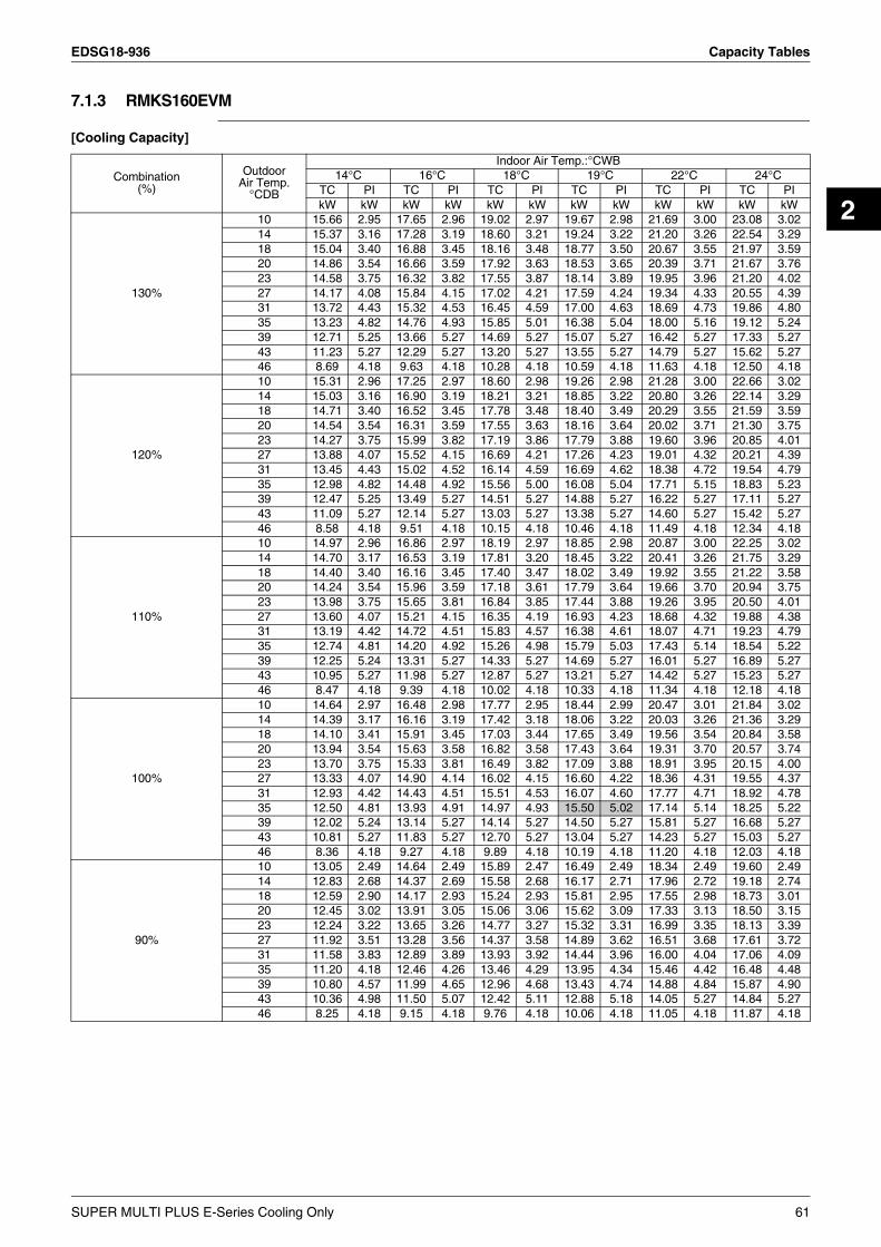
EDSG18-936 Capacity Tables
2
7.1.3 RMKS160EVM
[Cooling Capacity]
Combination(%)
OutdoorAir Temp.
°CDB
Indoor Air Temp.:°CWB14°C 16°C 18°C 19°C 22°C 24°C
TC PI TC PI TC PI TC PI TC PI TC PIkW kW kW kW kW kW kW kW kW kW kW kW
130%
10 15.66 2.95 17.65 2.96 19.02 2.97 19.67 2.98 21.69 3.00 23.08 3.02 14 15.37 3.16 17.28 3.19 18.60 3.21 19.24 3.22 21.20 3.26 22.54 3.29 18 15.04 3.40 16.88 3.45 18.16 3.48 18.77 3.50 20.67 3.55 21.97 3.59 20 14.86 3.54 16.66 3.59 17.92 3.63 18.53 3.65 20.39 3.71 21.67 3.76 23 14.58 3.75 16.32 3.82 17.55 3.87 18.14 3.89 19.95 3.96 21.20 4.02 27 14.17 4.08 15.84 4.15 17.02 4.21 17.59 4.24 19.34 4.33 20.55 4.39 31 13.72 4.43 15.32 4.53 16.45 4.59 17.00 4.63 18.69 4.73 19.86 4.80 35 13.23 4.82 14.76 4.93 15.85 5.01 16.38 5.04 18.00 5.16 19.12 5.24 39 12.71 5.25 13.66 5.27 14.69 5.27 15.07 5.27 16.42 5.27 17.33 5.27 43 11.23 5.27 12.29 5.27 13.20 5.27 13.55 5.27 14.79 5.27 15.62 5.27 46 8.69 4.18 9.63 4.18 10.28 4.18 10.59 4.18 11.63 4.18 12.50 4.18
120%
10 15.31 2.96 17.25 2.97 18.60 2.98 19.26 2.98 21.28 3.00 22.66 3.02 14 15.03 3.16 16.90 3.19 18.21 3.21 18.85 3.22 20.80 3.26 22.14 3.29 18 14.71 3.40 16.52 3.45 17.78 3.48 18.40 3.49 20.29 3.55 21.59 3.59 20 14.54 3.54 16.31 3.59 17.55 3.63 18.16 3.64 20.02 3.71 21.30 3.75 23 14.27 3.75 15.99 3.82 17.19 3.86 17.79 3.88 19.60 3.96 20.85 4.01 27 13.88 4.07 15.52 4.15 16.69 4.21 17.26 4.23 19.01 4.32 20.21 4.39 31 13.45 4.43 15.02 4.52 16.14 4.59 16.69 4.62 18.38 4.72 19.54 4.79 35 12.98 4.82 14.48 4.92 15.56 5.00 16.08 5.04 17.71 5.15 18.83 5.23 39 12.47 5.25 13.49 5.27 14.51 5.27 14.88 5.27 16.22 5.27 17.11 5.27 43 11.09 5.27 12.14 5.27 13.03 5.27 13.38 5.27 14.60 5.27 15.42 5.27 46 8.58 4.18 9.51 4.18 10.15 4.18 10.46 4.18 11.49 4.18 12.34 4.18
110%
10 14.97 2.96 16.86 2.97 18.19 2.97 18.85 2.98 20.87 3.00 22.25 3.02 14 14.70 3.17 16.53 3.19 17.81 3.20 18.45 3.22 20.41 3.26 21.75 3.29 18 14.40 3.40 16.16 3.45 17.40 3.47 18.02 3.49 19.92 3.55 21.22 3.58 20 14.24 3.54 15.96 3.59 17.18 3.61 17.79 3.64 19.66 3.70 20.94 3.75 23 13.98 3.75 15.65 3.81 16.84 3.85 17.44 3.88 19.26 3.95 20.50 4.01 27 13.60 4.07 15.21 4.15 16.35 4.19 16.93 4.23 18.68 4.32 19.88 4.38 31 13.19 4.42 14.72 4.51 15.83 4.57 16.38 4.61 18.07 4.71 19.23 4.79 35 12.74 4.81 14.20 4.92 15.26 4.98 15.79 5.03 17.43 5.14 18.54 5.22 39 12.25 5.24 13.31 5.27 14.33 5.27 14.69 5.27 16.01 5.27 16.89 5.27 43 10.95 5.27 11.98 5.27 12.87 5.27 13.21 5.27 14.42 5.27 15.23 5.27 46 8.47 4.18 9.39 4.18 10.02 4.18 10.33 4.18 11.34 4.18 12.18 4.18
100%
10 14.64 2.97 16.48 2.98 17.77 2.95 18.44 2.99 20.47 3.01 21.84 3.02 14 14.39 3.17 16.16 3.19 17.42 3.18 18.06 3.22 20.03 3.26 21.36 3.29 18 14.10 3.41 15.91 3.45 17.03 3.44 17.65 3.49 19.56 3.54 20.84 3.58 20 13.94 3.54 15.63 3.58 16.82 3.58 17.43 3.64 19.31 3.70 20.57 3.74 23 13.70 3.75 15.33 3.81 16.49 3.82 17.09 3.88 18.91 3.95 20.15 4.00 27 13.33 4.07 14.90 4.14 16.02 4.15 16.60 4.22 18.36 4.31 19.55 4.37 31 12.93 4.42 14.43 4.51 15.51 4.53 16.07 4.60 17.77 4.71 18.92 4.78 35 12.50 4.81 13.93 4.91 14.97 4.93 15.50 5.02 17.14 5.14 18.25 5.22 39 12.02 5.24 13.14 5.27 14.14 5.27 14.50 5.27 15.81 5.27 16.68 5.27 43 10.81 5.27 11.83 5.27 12.70 5.27 13.04 5.27 14.23 5.27 15.03 5.27 46 8.36 4.18 9.27 4.18 9.89 4.18 10.19 4.18 11.20 4.18 12.03 4.18
90%
10 13.05 2.49 14.64 2.49 15.89 2.47 16.49 2.49 18.34 2.49 19.60 2.49 14 12.83 2.68 14.37 2.69 15.58 2.68 16.17 2.71 17.96 2.72 19.18 2.74 18 12.59 2.90 14.17 2.93 15.24 2.93 15.81 2.95 17.55 2.98 18.73 3.01 20 12.45 3.02 13.91 3.05 15.06 3.06 15.62 3.09 17.33 3.13 18.50 3.15 23 12.24 3.22 13.65 3.26 14.77 3.27 15.32 3.31 16.99 3.35 18.13 3.39 27 11.92 3.51 13.28 3.56 14.37 3.58 14.89 3.62 16.51 3.68 17.61 3.72 31 11.58 3.83 12.89 3.89 13.93 3.92 14.44 3.96 16.00 4.04 17.06 4.09 35 11.20 4.18 12.46 4.26 13.46 4.29 13.95 4.34 15.46 4.42 16.48 4.48 39 10.80 4.57 11.99 4.65 12.96 4.68 13.43 4.74 14.88 4.84 15.87 4.90 43 10.36 4.98 11.50 5.07 12.42 5.11 12.88 5.18 14.05 5.27 14.84 5.27 46 8.25 4.18 9.15 4.18 9.76 4.18 10.06 4.18 11.05 4.18 11.87 4.18
SUPER MULTI PLUS E-Series Cooling Only 61

Capacity Tables EDSG18-936
80%
10 11.51 2.02 12.92 2.02 14.04 2.00 14.59 2.00 16.25 1.99 17.38 1.99 14 11.32 2.20 12.69 2.20 13.77 2.19 14.30 2.20 15.92 2.20 17.02 2.20 18 11.11 2.40 12.53 2.41 13.48 2.41 13.99 2.42 15.56 2.43 16.63 2.44 20 10.99 2.51 12.29 2.53 13.33 2.53 13.83 2.54 15.38 2.56 16.43 2.57 23 10.81 2.69 12.07 2.71 13.08 2.72 13.57 2.74 15.08 2.76 16.11 2.78 27 10.54 2.95 11.76 2.98 12.73 3.00 13.21 3.02 14.67 3.05 15.67 3.08 31 10.25 3.24 11.41 3.28 12.36 3.30 12.82 3.32 14.23 3.37 15.19 3.40 35 9.93 3.55 11.05 3.60 11.96 3.63 12.40 3.66 13.76 3.71 14.69 3.75 39 9.58 3.89 10.65 3.95 11.53 3.98 11.96 4.01 13.27 4.08 14.17 4.12 43 9.21 4.26 10.23 4.33 11.07 4.37 11.48 4.40 12.75 4.47 13.61 4.52 46 8.14 4.18 9.03 4.18 9.63 4.18 9.93 4.18 10.90 4.18 11.72 4.18
70%
10 10.02 1.57 11.32 1.56 12.24 1.55 12.72 1.54 14.19 1.52 15.19 1.51 14 9.85 1.72 11.12 1.72 12.01 1.71 12.47 1.71 13.90 1.70 14.87 1.69 18 9.67 1.90 10.99 1.90 11.76 1.90 12.21 1.90 13.60 1.90 14.54 1.90 20 9.57 2.00 10.77 2.00 11.62 2.00 12.07 2.00 13.44 2.01 14.37 2.01 23 9.41 2.15 10.58 2.16 11.41 2.17 11.85 2.17 13.19 2.18 14.10 2.19 27 9.18 2.38 10.31 2.40 11.12 2.41 11.54 2.42 12.84 2.43 13.72 2.45 31 8.93 2.63 10.02 2.66 10.80 2.67 11.21 2.68 12.46 2.71 13.32 2.73 35 8.66 2.91 9.70 2.94 10.45 2.96 10.85 2.97 12.06 3.01 12.89 3.03 39 8.37 3.21 9.37 3.25 10.09 3.27 10.47 3.29 11.64 3.33 12.44 3.36 43 8.05 3.53 9.00 3.58 9.70 3.61 10.07 3.63 11.20 3.67 11.97 3.71 46 7.80 3.79 8.72 3.84 9.40 3.88 9.75 3.89 10.85 3.95 11.53 3.98
60%
10 8.56 1.14 9.84 1.12 10.47 1.11 10.89 1.10 12.15 1.07 13.01 1.05 14 8.42 1.26 9.66 1.24 10.28 1.24 10.68 1.23 11.91 1.21 12.75 1.20 18 8.27 1.41 9.56 1.39 10.06 1.39 10.45 1.39 11.65 1.38 12.47 1.37 20 8.18 1.48 9.36 1.48 9.95 1.48 10.34 1.47 11.52 1.47 12.32 1.46 23 8.05 1.61 9.19 1.61 9.77 1.61 10.15 1.61 11.31 1.61 12.09 1.61 27 7.85 1.81 8.95 1.81 9.52 1.82 9.89 1.82 11.01 1.82 11.77 1.83 31 7.64 2.02 8.70 2.03 9.25 2.04 9.60 2.04 10.69 2.05 11.43 2.06 35 7.41 2.26 8.42 2.28 8.96 2.29 9.30 2.29 10.35 2.31 11.07 2.32 39 7.16 2.52 8.13 2.54 8.65 2.56 8.98 2.56 9.99 2.59 10.69 2.60 43 6.89 2.80 7.82 2.83 8.32 2.85 8.64 2.85 9.62 2.88 10.29 2.90 46 6.67 3.02 7.57 3.06 8.06 3.08 8.37 3.09 9.32 3.12 10.12 3.14
50%
10 7.16 0.73 8.47 0.69 8.75 0.68 9.09 0.67 10.15 0.65 10.87 0.63 14 7.04 0.81 8.31 0.78 8.58 0.77 8.92 0.77 9.95 0.75 10.65 0.74 18 6.90 0.92 8.23 0.90 8.40 0.89 8.73 0.88 9.73 0.87 10.41 0.86 20 6.83 0.98 8.04 0.96 8.31 0.95 8.63 0.95 9.61 0.94 10.29 0.93 23 6.71 1.08 7.89 1.07 8.15 1.06 8.47 1.06 9.44 1.05 10.10 1.05 27 6.55 1.23 7.68 1.22 7.94 1.22 8.25 1.22 9.18 1.22 9.82 1.22 31 6.36 1.40 7.45 1.40 7.71 1.40 8.01 1.40 8.91 1.41 9.54 1.41 35 6.17 1.60 7.20 1.61 7.46 1.60 7.75 1.61 8.63 1.62 9.23 1.62 39 5.95 1.81 6.94 1.83 7.20 1.83 7.48 1.83 8.33 1.85 8.91 1.86 43 5.72 2.05 6.66 2.07 6.92 2.07 7.19 2.08 8.01 2.10 8.57 2.11 46 5.54 2.24 6.44 2.27 6.70 2.27 6.96 2.28 7.76 2.30 8.25 2.32
Combination(%)
OutdoorAir Temp.
°CDB
Indoor Air Temp.:°CWB14°C 16°C 18°C 19°C 22°C 24°C
TC PI TC PI TC PI TC PI TC PI TC PIkW kW kW kW kW kW kW kW kW kW kW kW
Symbols NOTE:
TC : Total capacity (kW) 1. This table shows outdoor unit cooling capacity and power input.2. is specified point.3. PI of indoor units is not included in the table.
3D052907
PI : Power input (kW)
62 SUPER MULTI PLUS E-Series Cooling Only
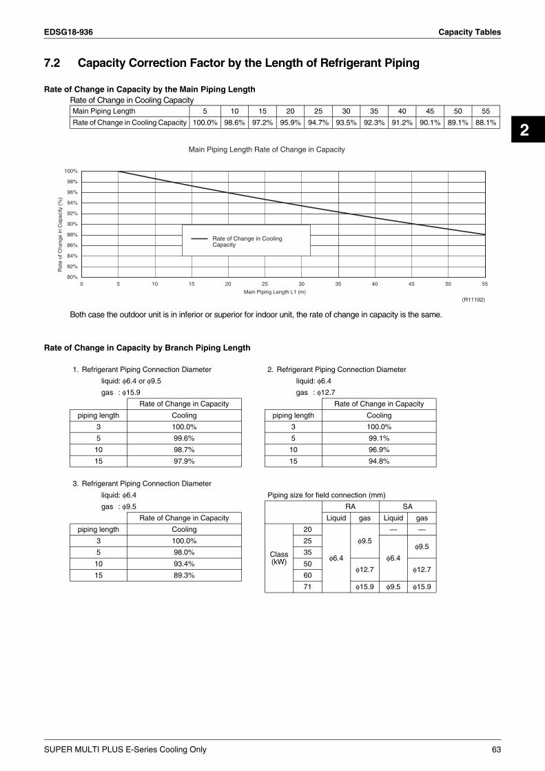
EDSG18-936 Capacity Tables
2
7.2 Capacity Correction Factor by the Length of Refrigerant Piping
Rate of Change in Capacity by the Main Piping LengthRate of Change in Cooling Capacity
Both case the outdoor unit is in inferior or superior for indoor unit, the rate of change in capacity is the same.
Rate of Change in Capacity by Branch Piping Length
Main Piping Length 5 10 15 20 25 30 35 40 45 50 55
Rate of Change in Cooling Capacity 100.0% 98.6% 97.2% 95.9% 94.7% 93.5% 92.3% 91.2% 90.1% 89.1% 88.1%
1. Refrigerant Piping Connection Diameter 2. Refrigerant Piping Connection Diameter
liquid: φ6.4 or φ9.5 liquid: φ6.4
gas : φ15.9 gas : φ12.7
Rate of Change in Capacity Rate of Change in Capacity
piping length Cooling piping length Cooling
3 100.0% 3 100.0%
5 99.6% 5 99.1%
10 98.7% 10 96.9%
15 97.9% 15 94.8%
3. Refrigerant Piping Connection Diameter
liquid: φ6.4 Piping size for field connection (mm)
gas : φ9.5 RA SA
Rate of Change in Capacity Liquid gas Liquid gas
piping length Cooling
Class(kW)
20
φ6.4
φ9.5
— —
3 100.0% 25
φ6.4
φ9.55 98.0% 35
10 93.4% 50φ12.7 φ12.7
15 89.3% 60
71 φ15.9 φ9.5 φ15.9
80%
82%
84%
86%
88%
90%
92%
94%
96%
98%
100%
Rat
e of
Cha
nge
in C
apac
ity (
%)
Main Piping Length Rate of Change in Capacity
0 5 10 15 20 25 30 35 40 45 50 55
Main Piping Length L1 (m)
Rate of Change in CoolingCapacity
(R11192)
SUPER MULTI PLUS E-Series Cooling Only 63

Capacity Tables EDSG18-936
Note: 1. These figures illustrate the rate of change in capacity of a standard indoor unit system at maximum load(with the thermostat set to maximum) under standard conditions.Moreover, under partial load conditions there is only a minor deviation from the rate of change in capacity shown in the above figures.
2. With this outdoor unit, evaporating pressure constant control when cooling, and condensing pressure constant control when heating is carried out.
3. System layout of piping
95%
96%
97%
98%
99%
100%
Rat
e of
Cha
nge
in C
apac
ity (
%)
Refrigerant Piping Connection Diameter liquid: φ6.4, gas: φ15.9liquid: φ9.5, gas: φ15.9
0 5 10 15
Branch piping length L2 (m)
Cooling
(R11194)
90%
91%
92%
93%
94%
95%
96%
97%
98%
99%
100%
Rat
e of
Cha
nge
in C
apac
ity (
%)
Refrigerant Piping Connection Diameter liquid: φ6.4, gas: φ12.7
0 5 10 15
Branch piping length L2 (m)
Cooling
(R11193)
88%
90%
92%
94%
96%
98%
100%
Rat
e of
Cha
nge
in C
apac
ity (
%)
Refrigerant Piping Connection Diameter liquid: φ6.4, gas: φ9.5
0 5 10 15
Branch piping length L2 (m)
Cooling
(R11195)
[Method of calculating cooling/heating capacity]Total capacity from capacity tables × (Rate of change in capacity by main piping length × Rate of change in capacity by branch piping length)
C: 3D050529
Piping length : L1 = 5m, L2 = 3m
L2L1
BP unit Indoor unit
Outdoor unit5m 3m
(R4882)
64 SUPER MULTI PLUS E-Series Cooling Only

EDSG18-936 Operation Limit
2
8. Operation LimitRMKS112EVM, RMKS140EVM, RMKS160EVM
Notes:The graphs are basedon the following conditions.• Equivalent piping length
From outdoor unit to BP unitFrom BP unit to each indoor units
• Level difference• Air flow rate
5m3m0mHigh
Out
door
tem
p.( °
CD
B)
46
-5
50
30
40
20
10
0
10 14Indoor temp.( °CWB)
(50/60Hz)
Cooling
Con
tinuo
us o
pera
tion
20 23
Pull-
dow
n pe
riod
28 30
3D049155C
SUPER MULTI PLUS E-Series Cooling Only 65

Fan Characteristics EDSG18-936
9. Fan Characteristics
FDKS25CAVMB
FDKS35CAVMB
(mmH2O)
7
6
5
4
3
2
(mmH2O)
1
Exte
rnal
sta
tic p
ress
ure
(Pa)
(Pa)70
60
50
40
30
20
10
6
SL
7
Upper
limit o
f exte
rnal
static
pres
sure
Air flow rate (m3/min)8
L
9
H
Lower limit of external
static pressure
10 11 (mmH2O)
(mmH2O)7
6
5
4
3
2
1
3D045760E
(mmH2O)
7
5
6
4
3
2
(mmH2O)
1
(Pa)
(Pa)70
50
60
30
20
10
6 7
SL
Air flow rate (m3/min)8
L
9 10
H
11 (mmH2O)
(mmH2O)7
5
6
3
4
2
1
Upper limit o
f exte
rnal
static
pressure
Lower limit of external
static pressure
Exte
rnal
sta
tic p
ress
ure
40
3D045761E
66 SUPER MULTI PLUS E-Series Cooling Only

EDSG18-936 Fan Characteristics
2
FDKS50CVMB
FDKS60CVMB
(mmH2O)
7
6
5
3
2
4
(mmH2O)
1
(Pa)
(Pa)70
60
50
30
20
10
8 9
SL
10
L
Air flow rate (m3/min)11 12
H
13 14 (mmH2O)
(mmH2O)7
6
5
3
2
4
1
Upper limit o
f exte
rnal
static
pressure
Lower limit of external
static pressure
Exte
rnal
sta
tic p
ress
ure
40
3D045762D
(mmH2O)
7
6
5
4
3
2
(mmH2O)
1
(Pa)
(Pa)70
60
50
40
30
20
10
9.5
SL
10.5 11.5
L
12.5Air flow rate (m3/min)
13.5
H
14.5 15.5 16.5 17.5 (mmH2O)
(mmH2O)7
6
5
4
3
2
1
Lower limit of external
static pressure
Upper limit o
f external
static
pressure
Exte
rnal
sta
tic p
ress
ure
3D045763D
SUPER MULTI PLUS E-Series Cooling Only 67

Fan Characteristics EDSG18-936
FDKS25EAVMB, FDKS35EAVMB
FBQ60BV1, FBQ71BV1
(mmH O)
6
4
2
3
5
7(mmH O)
1
2
2
Exte
rnal
sta
tic p
ress
ure
(Pa)
(Pa)
40
70
20
50
60
30
10
5 6
Upper
of lim
it exte
rnal
static
pressu
re
SL
7
Air flow rate(m /min)
L
83
H
9 10 11 (mmH O)
(mmH O)
2
2
6
7
5
4
3
2
1
3D051853
(mmH2O)
(mmH2O)50HZ 220V
5
15
10
23
01
Notes:
Exte
rnal
Inte
rnal
stat
ic p
ress
ure
stat
ic p
ress
ure
150
100
(Pa)
(Pa)
50
30
20
40
0
10
Low
14
High(standerd ESP)
Lower limit of external
static pressure(high ESP)
High(Low ESP)
Air flow(m3/min)16 18
High(high ESP)
20 21(mmH2O)
5
32
4
01
15
10
Intake panelLong lifefilter
(mmH2O)
(mmH2O) (mmH2O) (mmH2O)
(mmH2O)
60HZ 220V
5
15
10
23
01
Exte
rnal
Inte
rnal
stat
ic p
ress
ure
stat
ic p
ress
ure
150
100
(Pa)
(Pa)
50
20
30
40
0
10
Low
14
Lower limit of external
static pressure(high ESP)
Upper lim
it of ext
ernal
static p
ressure(
high ESP)
High(standerd ESP)
Air flow(m3/min)16
High(Low ESP)
18
High(high ESP)
20 21
5
32
4
01
15
10
Intake panelLong lifefilter
3D049455
1.The remorte controller can be used to switch between "high" and "low".2.The air flow is set to "standerd" before leaving the factory. It is possible
to switch between "standerd ESP" and "high ESP" by changing the terminals in the indoor unit electrical box.
3.The external static pressure indicates the characteristics of the fan when a suction panel (optional accessory)and a canvas for the suction panel (optional accessory) are incorporated into the main unit (with a long-life filter).
Upper lim
it of ext
ernal
static p
ressur
e(high
ESP)
68 SUPER MULTI PLUS E-Series Cooling Only

EDSG18-936 Sound Level
2
10.Sound Level10.1 Measuring Location
Note: 1. Operation sound is measured in an anechoic chamber.2. The data are based on the conditions shown in the table below.
Indoor UnitsWall Mounted Type Duct Connected Type
Ceiling Mounted Cassette Type Ceiling Mounted Built-in Type
Outdoor Units
1m
0.8m
(R1759)
DUCT
(R4124)
2m
1.5m
MICROPHONE
DUCT
1m
(R4948)
0.67m1m
Cooling Piping Length
Indoor ; 27°CDB/19°CWBOutdoor ; 35°CDB 5m
SUPER MULTI PLUS E-Series Cooling Only 69

Sound Level EDSG18-936
10.2 Octave Band Level10.2.1 Outdoor Units
10.2.2 Indoor Units
RMKS112EVM RMKS140EVM
RMKS160EVM
COOLING
220-240V 50Hz220-230V 60Hz
C52
68.5
RETURN AIR TEMPERATURE: 27°CDB, 19.0°CWBOUTDOOR TEMPERATURE: 35°CDB, 24°CWB
220-240V 50Hz
NC-40
NC-30
NC-50
NC-60
NC-20
COOLING
POWER SOURCE
OPERATING CONDITIONS
OC
TAVE
BAN
D S
OU
ND
PR
ESSU
RE
LEVE
LdB
( 0dB
=0.0
002µ
bar
)
70
60
20
30
50
40
THRESHOLD HEARINGAPPROXIMATE
FOR CONTINUOUSNOISE
63 125OCTAVE BAND CENTER FREQUENCY (Hz)
250 500 1000 2000 4000 8000
OVER ALL ( dB )
SCALE
A
( B.G.N IS ALREADY RECTIFIED )
220-230V 60Hz
4D049260A
COOLING
C5369
RETURN AIR TEMPERATURE: 27°CDB, 19.0°CWBOUTDOOR TEMPERATURE: 35°CDB, 24°CWB
220-240V 50Hz
NC-40
NC-30
NC-50
NC-60
NC-20
COOLING
POWER SOURCE
OPERATING CONDITIONS
OC
TAVE
BAN
D S
OU
ND
PR
ESSU
RE
LEVE
LdB
( 0dB
=0.0
002µ
bar
)
70
60
20
30
50
40
THRESHOLD HEARINGAPPROXIMATE
FOR CONTINUOUSNOISE
63 125OCTAVE BAND CENTER FREQUENCY (Hz)
250 500 1000 2000 4000 8000
OVER ALL ( dB )
SCALE
A
( B.G.N IS ALREADY RECTIFIED )
220-230V 60Hz
220-240V 50Hz220-230V 60Hz
4D049261A
COOLING
220-240V 50Hz220-230V 60Hz
C
54
69
RETURN AIR TEMPERATURE: 27°CDB, 19.0°CWBOUTDOOR TEMPERATURE: 35°CDB, 24°CWB
220-240V 50Hz
NC-40
NC-30
NC-50
NC-60
NC-20
COOLING
POWER SOURCE
OPERATING CONDITIONS
OC
TAVE
BAN
D S
OU
ND
PR
ESSU
RE
LEVE
LdB
( 0dB
=0.0
002µ
bar
)
70
60
20
30
50
40
THRESHOLD HEARINGAPPROXIMATE
FOR CONTINUOUSNOISE
63 125OCTAVE BAND CENTER FREQUENCY (Hz)
250 500 1000 2000 4000 8000
OVER ALL ( dB )
SCALE
A
( B.G.N IS ALREADY RECTIFIED )
220-230V 60Hz
4D049262A
FTKS25DVM FTKS35DVM
FTKS50FVM FTKS60FVM
NC-40
NC-30
NC-50
NC-60
NC-20
STANDARD EXTERNAL STATIC PRESSURE50/60Hz 220-240/220-230V(H)
50/60Hz 220-240/220-230V(L)
50/60Hz220-240/220-230V
(H)
37
50/60Hz220-240/220-230V
(L)
25
POWER SOURCE
JIS STANDARD
OPERATING CONDITIONS
OC
TAV
E B
AN
D S
OU
ND
PR
ES
SU
RE
LE
VE
LdB
( 0dB
=0.
0002
µ ba
r)
70
60
20
30
50
40
THRESHOLD HEARINGAPPROXIMATE
FOR CONTINUOUSNOISE
63 125OCTAVE BAND CENTER FREQUENCY (Hz)
250 500 1000 2000 4000 8000
OVER ALL ( dB )
SCALE
A
( B.G.N IS ALREADY RECTIFIED )
220-240/220-230V 50/60Hz
4D048279C
OC
TAVE
BAN
D S
OU
ND
PR
ESSU
RE
LEVE
LdB
( 0dB
=0.0
002µ
bar
)
70
20
60
30
50
40
OCTAVE BAND CENTER FREQUENCY (Hz)63 125 250 500 1000
NC-40
NC-30
NC-50
NC-20
NC-60
2000 4000 8000 4D048814
APPROXIMATETHRESHOLD HEARINGFOR CONTINUOUSNOISE
STANDARD EXTERNAL STATIC PRESSURE
POWER SOURCE 220-240/220-230V 50/60Hz
SCALE
(B.G.N IS ALREADY RECTIFIED)
OPERATING CONDITIONS
A
50/60Hz 220-240/220-230v(H)
50/60Hz 220-240/220-230v(L)
50/60Hz220-240/220-230v
(H)
OVER ALL(dB)
JIS STANDARD
39
50/60Hz220-240/220-230v
(L)
26
NC-20
(L)(H)220-240/220-230V
NC-50
Cooling
220-240/220-230V
NC-30
50/60Hz
43
NC-60
NC-40
34
50/60Hz
50/60Hz 220-240/220-230V(H)
50/60Hz 220-240/220-230V(L)
220-240/220-230V 50/60HzPOWER SOURCE
JIS STANDARD
OPERATING CONDITIONS
OC
TAV
E B
AN
D S
OU
ND
PR
ES
SU
RE
LE
VE
LdB
( 0dB
=0.
0002
µ ba
r)
70
60
20
30
50
40
THRESHOLD HEARINGAPPROXIMATE
FOR CONTINUOUSNOISE
63 125OCTAVE BAND CENTER FREQUENCY (Hz)
250 500 1000 2000 4000 8000
OVER ALL ( dB )
SCALE
A
( B.G.N IS ALREADY RECTIFIED )
4D056195A
NC-40
NC-30
NC-50
NC-60
NC-20
50/60Hz 220-240/220-230V(H)
50/60Hz 220-240/220-230V(L)
50/60Hz220-240/220-230V
(H)
220-240/220-230V 50/60Hz
45
50/60Hz220-240/220-230V
(L)
36
Cooling
POWER SOURCE
JIS STANDARD
OPERATING CONDITIONS
OC
TAV
E B
AN
D S
OU
ND
PR
ES
SU
RE
LE
VE
LdB
( 0dB
=0.
0002
µ ba
r)
70
60
20
30
50
40
THRESHOLD HEARINGAPPROXIMATE
FOR CONTINUOUSNOISE
63 125OCTAVE BAND CENTER FREQUENCY (Hz)
250 500 1000 2000 4000 8000
OVER ALL ( dB )
SCALE
A
( B.G.N IS ALREADY RECTIFIED )
4D040304G
70 SUPER MULTI PLUS E-Series Cooling Only
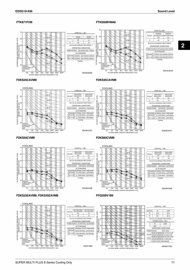
EDSG18-936 Sound Level
2
FTKS71FVM FTKS50BVMA8
FDKS25CAVMB FDKS35CAVMB
FDKS50CVMB FDKS60CVMB
FDKS25EAVMB, FDKS35EAVMB FFQ25BV1B9
NC-40
NC-30
NC-50
NC-60
NC-20
Cooling
50/60Hz 220-240/220-230V(H)
50/60Hz 220-240/220-230V(L)
50/60Hz220-240/220-230V
(H)
46
50/60Hz220-240/220-230V
(L)
37
POWER SOURCE
JIS STANDARD
OPERATING CONDITIONS
OC
TAV
E B
AN
D S
OU
ND
PR
ES
SU
RE
LE
VE
LdB
( 0dB
=0.
0002
µ ba
r)
70
60
20
30
50
40
THRESHOLD HEARINGAPPROXIMATE
FOR CONTINUOUSNOISE
63 125OCTAVE BAND CENTER FREQUENCY (Hz)
250 500 1000 2000 4000 8000
OVER ALL ( dB )
SCALE
A
( B.G.N IS ALREADY RECTIFIED )
220-240/220-230V 50/60Hz
4D040305K
NC-40
NC-30
NC-50
NC-60
NC-20
4D040303A
OC
TAVE
BAN
D S
OU
ND
PR
ESSU
RE
LEVE
LdB
( 0dB
=0.0
002µ
bar
)
70
60
20
30
50
40
THRESHOLD HEARINGAPPROXIMATE
FOR CONTINUOUSNOISE
63 125OCTAVE BAND CENTER FREQUENCY (Hz)
250 500 1000 2000 4000 8000
Cooling
POWER SOURCE 220-240/220-230V 50/60Hz
SCALE
(B.G.N IS ALREADY RECTIFIED)
OPERATING CONDITIONS
A
50/60Hz220-240/220-230V
(H)
OVER ALL(dB)
44
50/60Hz220-240/220-230V
(L)
35
50/60Hz 220-240/220-230V(H)
50/60Hz 220-240/220-230V(L)
JIS STANDARD
COOLING
NC-40
NC-30
NC-50
NC-60
NC-20
50Hz/230V60Hz/220V
(H)35
50Hz/230V60Hz/220V
(L)31
(L) 230V/50Hz, 220V/60Hz
(H) 230V/50Hz, 220V/60Hz
Cooling
STANDARD EXTERNAL STATIC PRESSURE
POWER SOURCE
JIS STANDARD
OPERATING CONDITIONS
OC
TAVE
BAN
D S
OU
ND
PR
ESSU
RE
LEVE
LdB
( 0dB
=0.0
002µ
bar
)
70
60
20
30
50
40
THRESHOLD HEARINGAPPROXIMATE
FOR CONTINUOUSNOISE
63 125OCTAVE BAND CENTER FREQUENCY (Hz)
250 500 1000 2000 4000 8000
OVER ALL ( dB )
SCALE
A
( B.G.N IS ALREADY RECTIFIED )
230V/50Hz, 220V/60Hz
4D046333C
COOLING
NC-40
NC-30
NC-50
NC-60
NC-20
50Hz/230V60Hz/220V
(H)35
50Hz/230V60Hz/220V
(L)31
(L) 230V/50Hz, 220V/60Hz
(H) 230V/50Hz, 220V/60Hz
Cooling
STANDARD EXTERNAL STATIC PRESSURE
POWER SOURCE
JIS STANDARD
OPERATING CONDITIONS
OC
TAVE
BAN
D S
OU
ND
PR
ESSU
RE
LEVE
LdB
( 0dB
=0.0
002µ
bar
)
70
60
20
30
50
40
THRESHOLD HEARINGAPPROXIMATE
FOR CONTINUOUSNOISE
63 125OCTAVE BAND CENTER FREQUENCY (Hz)
250 500 1000 2000 4000 8000
OVER ALL ( dB )
SCALE
A
( B.G.N IS ALREADY RECTIFIED )
230V/50Hz, 220V/60Hz
4D046334C
COOLING
NC-40
NC-30
NC-50
NC-60
NC-20
50Hz/230V60Hz/220V
(H)37
50Hz/230V60Hz/220V
(L)
33
(L) 230V/50Hz, 220V/60Hz
(H) 230V/50Hz, 220V/60Hz
Cooling
STANDARD EXTERNAL STATIC PRESSURE
POWER SOURCE
JIS STANDARD
OPERATING CONDITIONS
OC
TAVE
BAN
D S
OU
ND
PR
ESSU
RE
LEVE
LdB
( 0dB
=0.0
002µ
bar
)
70
60
20
30
50
40
THRESHOLD HEARINGAPPROXIMATE
FOR CONTINUOUSNOISE
63 125OCTAVE BAND CENTER FREQUENCY (Hz)
250 500 1000 2000 4000 8000
OVER ALL ( dB )
SCALE
A
( B.G.N IS ALREADY RECTIFIED )
230V/50Hz, 220V/60Hz
4D046335B
COOLING
NC-40
NC-30
NC-50
NC-60
NC-20
50Hz/230V60Hz/220V
(H)
38
50Hz/230V60Hz/220V
(L)
34
(L) 230V/50Hz, 220V/60Hz
(H) 230V/50Hz, 220V/60Hz
Cooling
STANDARD EXTERNAL STATIC PRESSURE
POWER SOURCE
JIS STANDARD
OPERATING CONDITIONS
OC
TAVE
BAN
D S
OU
ND
PR
ESSU
RE
LEVE
LdB
( 0dB
=0.0
002µ
bar
)
70
60
20
30
50
40
THRESHOLD HEARINGAPPROXIMATE
FOR CONTINUOUSNOISE
63 125OCTAVE BAND CENTER FREQUENCY (Hz)
250 500 1000 2000 4000 8000
OVER ALL ( dB )
SCALE
A
( B.G.N IS ALREADY RECTIFIED )
230V/50Hz, 220V/60Hz
4D046336B
COOLING
NC-40
NC-30
NC-50
NC-20
NC-60
STANDARD EXTERNAL STATIC PRESSURE
Cooling(L)220-240V/50Hz, 220-230V/60Hz
(H)220-240V/50Hz, 220-230V/60Hz
220-230V/60Hz220-240V/50Hz
220-240V/50Hz, 220-230V/60Hz
35
(H)220-230V/60Hz220-240V/50Hz
(L)
31
POWER SOURCE
JIS STANDARD
OPERATING CONDITIONS
OC
TAVE
BAN
D S
OU
ND
PR
ESSU
RE
LEVE
LdB
( 0dB
=0.0
002µ
bar
)
70
60
20
30
50
40
THRESHOLD HEARINGAPPROXIMATE
FOR CONTINUOUSNOISE
63 125OCTAVE BAND CENTER FREQUENCY (Hz)
250 500 1000 2000 4000 8000
OVER ALL ( dB )
SCALE
A
( B.G.N IS ALREADY RECTIFIED )
4D051868
NC-40
NC-30
NC-50
NC-60
NC-20
LOW
HI
HI LOW
HI
46.5
LOW-
POWER LEVEL ( dB )
4 DIRECTION DISCHARGE
RETURN AIR TEMPERATURE : 27°C DB, 19°C WBOUTDOOR TEMPERATURE : 35°C DB, 24°C WBCOOLING
RETURN AIR TEMPERATURE : 20°C DB, 15°C WBOUTDOOR TEMPERATURE : 7°C DB, 6°C WBHEATING
POWER SOURCE
OPERATING CONDITIONS
OC
TAV
E B
AN
D S
OU
ND
PR
ES
SU
RE
LE
VE
LdB
( 0dB
=0.
0002
µ ba
r)
70
60
20
30
50
40
THRESHOLD HEARINGAPPROXIMATE
FOR CONTINUOUSNOISE
63 125OCTAVE BAND CENTER FREQUENCY (Hz)
250 500 1000 2000 4000 8000
OVER ALL ( dB )
SCALE
A
( B.G.N IS ALREADY RECTIFIED )
C
230V 50Hz
36.1
29.5
32.3
24.5
4D040176A
SUPER MULTI PLUS E-Series Cooling Only 71

Sound Level EDSG18-936
FFQ35BV1B9 FFQ50BV1B9
FFQ60BV1B9 FCQ35BVE, FCQ50BVE
FCQ60BVE, FCQ71BVE FBQ60BV1, FBQ71BV1
NC-40
NC-30
NC-50
NC-60
NC-20
LOW
HI
HI LOW
4 DIRECTION DISCHARGE
RETURN AIR TEMPERATURE : 27°C DB, 19°C WBOUTDOOR TEMPERATURE : 35°C DB, 24°C WB
COOLING
RETURN AIR TEMPERATURE : 20°C DB, 15°C WBOUTDOOR TEMPERATURE : 7°C DB, 6°C WB
HEATING
HI
49.0
LOW-
POWER LEVEL ( dB )
POWER SOURCE
OPERATING CONDITIONS
OC
TAV
E B
AN
D S
OU
ND
PR
ES
SU
RE
LE
VE
LdB
( 0dB
=0.
0002
µ ba
r)
70
60
20
30
50
40
THRESHOLD HEARINGAPPROXIMATE
FOR CONTINUOUSNOISE
63 125OCTAVE BAND CENTER FREQUENCY (Hz)
250 500 1000 2000 4000 8000
OVER ALL ( dB )
SCALE
A
( B.G.N IS ALREADY RECTIFIED )
C 38.0
32.0
32.7
25.0
230V 50Hz
LOW
4D040177A
NC-40
NC-30
NC-50
NC-60
NC-20
LOW
HI
4 DIRECTION DISCHARGE
HEATING
COOLINGRETURN AIR TEMPERATURE:27°C DB, 19°C WB
RETURN AIR TEMPERATURE:20°C DB, 15°C WBOUTDOOR TEMPERATURE:35°C DB, 24°C WB
OUTDOOR TEMPERATURE:7°C DB, 6°C WB
36.0
41.0
HI
34.2
27.0
LOW
C
53.0
HI LOW
POWER LEVEL ( dB )
POWER SOURCE
OPERATING CONDITIONS
OC
TAV
E B
AN
D S
OU
ND
PR
ES
SU
RE
LE
VE
LdB
( 0dB
=0.
0002
µ ba
r)
70
60
20
30
50
40
THRESHOLD HEARINGAPPROXIMATE
FOR CONTINUOUSNOISE
63 125OCTAVE BAND CENTER FREQUENCY (Hz)
250 500 1000 2000 4000 8000
OVER ALL ( dB )
SCALE
A
( B.G.N IS ALREADY RECTIFIED )
230V 50Hz
4D040178A
NC-40
NC-30
NC-50
NC-60
NC-20
LOW
HI
4 DIRECTION DISCHARGE
HEATING
COOLING
C
RETURN AIR TEMPERATURE:20°C DB, 15°CWB
RETURN AIR TEMPERATURE:27°C DB, 19°CWB
OUTDOOR TEMPERATURE:7°C DB, 6°CWB
OUTDOOR TEMPERATURE:35°C DB, 24°CWB
44.8
41.0
HI
32.0
38.0
LOW
58.0
HI LOW
POWER LEVEL ( dB )
POWER SOURCE
OPERATING CONDITIONS
OC
TAV
E B
AN
D S
OU
ND
PR
ES
SU
RE
LE
VE
LdB
( 0dB
=0.
0002
µ ba
r)
70
60
20
30
50
40
THRESHOLD HEARINGAPPROXIMATE
FOR CONTINUOUSNOISE
63 125OCTAVE BAND CENTER FREQUENCY (Hz)
250 500 1000 2000 4000 8000
OVER ALL ( dB )
SCALE
A
( B.G.N IS ALREADY RECTIFIED )
230V 50Hz
4D040179A
L(240V)
H(240V)
L(220V)
NC-40
NC-30
NC-50
NC-60
NC-20
H(220V)
4D006198C
OC
TAVE
BAN
D S
OU
ND
PR
ESSU
RE
LEVE
LdB
( 0dB
=0.0
002µ
bar
)
70
60
20
30
50
40
THRESHOLD HEARINGAPPROXIMATE
FOR CONTINUOUSNOISE
63 125OCTAVE BAND CENTER FREQUENCY (Hz)
250 500 1000 2000 4000 8000
220V
H L H L
240V
39
POWER SOURCE 50Hz/60Hz
JIS STANDARD
OPERATING CONDITIONS
OVER ALL ( dB )
SCALE
C
33
35
29
41
35
37
31A
( B.G.N IS ALREADY RECTIFIED )
240V
220V
4D006201D
L(240V)
L(220V)
H(240V)NC-40
NC-30
NC-50
NC-60
NC-20
H(220V)
APPROXIMATETHRESHOLD HEARINGFOR CONTINUOUSNOISE
OCTAVE BAND CENTER FREQUENCY (Hz)63 125 250 500 1000 2000 4000 8000
OC
TAVE
BAN
D S
OU
ND
PR
ESSU
RE
LEVE
LdB
(0dB
=0.0
002µ
bar
)
70
60
20
30
50
40
220V
H L H L
240V
41
POWER SOURCE 50Hz/60Hz
JIS STANDARD
OPERATING CONDITIONS
OVER ALL ( dB )
SCALE
C
35
36
30
43
37
38
32A
( B.G.N IS ALREADY RECTIFIED )
240V
220V L(240V)
L(220V)
H(240V)H(220V)
NC-40
NC-30
NC-50
NC-60
NC-20
OC
TAVE
BAN
D S
OU
ND
PR
ESSU
RE
LEVE
LdB
( 0dB
=0.0
002µ
bar
)
70
60
20
30
50
40
THRESHOLD HEARINGAPPROXIMATE
FOR CONTINUOUSNOISE
63 125OCTAVE BAND CENTER FREQUENCY (Hz)
250 500 1000 2000 4000 8000 DU426-4186A
220V
H L H L
240V
48
POWER SOURCE 220V • 240V 50Hz
JIS STANDARD
OPERATING CONDITIONS
OVER ALL ( dB )
SCALE
B
41
43
35
50
43
45
37A
( B.G.N IS ALREADY RECTIFIED )
240V
220V
STANDARD ESP 49Pa (H)
72 SUPER MULTI PLUS E-Series Cooling Only

EDSG18-936 Electric Characteristics
2
11.Electric Characteristics
C : 3D052890
Model Units Power supply Comp. OFMOutdoor Hz Volts Min. Max. MCA MFA MSC RLA W FLA
RMKS112EVM Cooling 50 230 198 253 27.0 30 15.4 15.488+88
0.4+
0.4
RMKS140EVM Cooling 50 230 198 253 27.0 30 19.7 19.788+88
0.4+
0.4
RMKS160EVM Cooling 50 230 198 253 27.0 30 23.5 23.588+88
0.4+
0.4
SYMBOLS: NOTE:MCA : MIN. CIRCUIT AMPS (A) 1. RLA is based on the following conditions.
Power Supply: 50Hz 230VCoolingIndoor temp.: 27°CDB/19°CWBOutdoor temp.: 35°CDB.
2. Voltage range.Units are suitable for use on electrical systems where voltage supplied to unit terminal is not below or above listed range limits.
3. Maximum allowable voltage variation between phases is 2%.4. Select wire size based on the value of MCA.5. MCA represents maximum input current.
MFA represents capacity which may accept MCA.6. Instead of fuse, use circuit breaker.7. MFA is used to select the circuit breaker and the ground fault
circuit interrupter (earth leakage circuit breaker).8. Be sure to install an earth leak detector. (One that can handle
higher harmonics.)(This unit uses an inverter, which means that it must be used an earth leak detector capable handling high harmonics in order to prevent malfunctioning of the earth leak detector itself.)
MFA : MAX. FUSE AMPS (A)MSC : MAX. CURRENT DURING THE
STARTING COMPRESSOR (A)RLA : RATED LOAD AMPS (A)OFM : OUTDOOR FAN MOTORFLA : FULL LOAD AMPS (A)W : FAN MOTOR RATED OUTPUT (W)
SUPER MULTI PLUS E-Series Cooling Only 73
Electric Characteristics EDSG18-936
74 SUPER MULTI PLUS E-Series Cooling Only
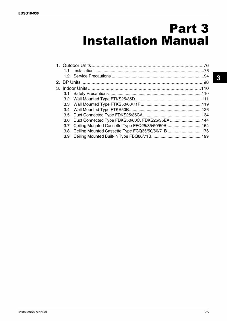
EDSG18-936
Installation Manual 75
3
Part 3Installation Manual
1. Outdoor Units ........................................................................................761.1 Installation ..............................................................................................761.2 Service Precautions ...............................................................................94
2. BP Units ................................................................................................983. Indoor Units.........................................................................................110
3.1 Safety Precautions ...............................................................................1103.2 Wall Mounted Type FTKS25/35D.........................................................1113.3 Wall Mounted Type FTKS50/60/71F ....................................................1193.4 Wall Mounted Type FTKS50B..............................................................1263.5 Duct Connected Type FDKS25/35CA..................................................1343.6 Duct Connected Type FDKS50/60C, FDKS25/35EA ...........................1443.7 Ceiling Mounted Cassette Type FFQ25/35/50/60B..............................1543.8 Ceiling Mounted Cassette Type FCQ35/50/60/71B .............................1763.9 Ceiling Mounted Built-in Type FBQ60/71B...........................................199

Outdoor Units EDSG18-936
1. Outdoor Units1.1 Installation
figure 1
23
4
5 2
1
≥1,0
00≥1
,000
≥1,5
00
≥1,500
≥1,500
[1] [2]
[3]100 or m
ore
100 or more
300 or more
100 or more
100 or more
200 or more
100 or more
figure 4
figure 7
1
2
4 5
6 7
8
3
figure 2
1
2
3
4
5
6
5
figure 3
[1] [2]
[3]
100 or more
150 or more
500 or
more1000 or
more
150 or more150 or more
1000 or more
500 or more
500 or more
1000 or more
1000 or more
200 or more300 or m
ore
figure 5
[1] [2]
[3] [4]
500 or more
500 or
more500 or
more
500 or more
1000 or more
1000 or more
1000 or more
1000 or more
figure 6
[1] [2]
L
L L
A A
L
H
H H
H
500 or
more
250 or
more 300 or
more
500 or
less500 or
less
100 or
more
300 or
more
1000 or more
L > HL > H
[3] [4]1000 or
more 1000 or more
figure 7
[5] [6] [7] [8]
LL
LL
HH
H H
AA A500 or
more
500 or
more500 or
more
100 or
more
1000 or
more
1000 or
more 1500 or
more
1000 or more
1000 or more
L > H
76 Installation Manual

EDSG18-936 Outdoor Units
3
[1]
[2]
Z
Z
1000 or more
300 or more
100
100
figure 8 figure 9
1
2
22
3
3
9
10
11
3
7
4
5
5
68
figure 16
1 4
2
3
L N
11
910
8
7
6
5
5
[1]
[2]
1000 or
more
2000 or
more
200 or
more
100 or
more
1500 or
more
600 or
more
3000 or
moreH
A
L
1
20
figure 10
1
2
7
3
4
65
1
2
3
140 140
421
45
612
620
35021
9 117
3029
0
(345
~35
5)
12
3
4
5
6
7
1
4
4
3
4
4
3
3
3
5
5
9
9
9
8
8
8
8
8
8
8
8
9
9
9
8
8
8
8
8
8
8
8
6
6
7
77
7
6
6
7
7
10
10
10
10
⟨ ⟩
2⟨ ⟩
figure 12
figure 11
figure 13 figure 14
figure 15
1
2
3
140 140
421
45
612
620
35021
9 117
3029
0
(345
~35
5)
Installation Manual 77

Outdoor Units EDSG18-936
F1 F2
F1TO BP UNIT TO OUT/D UNIT
F2 F1 F2
F1 F2 F1 F2
1
2
3
4
1
2
3
56
8
47
1
2 3
4
5
[1] [2] [3] [4]1
22
2 233
4
5
4
5
63
3
4
4655
1 1 1
figure 25
figure 29
1 23
4
4
56
figure 30
figure 17
figure 21
figure 31
1 1
23
F1F2F1F2
F1F2 F1F2F1F2F1F2
figure 18 figure 19
1
2
3
4
56
A
figure 20
12
34
412
figure 22 figure 23 figure 24
12
1
2
3
4 5
6
1
2
3
4
5 6
7 711
12 12
1089
figure 26 figure 27 figure 28
1
2
3 4
5
678
1012
3
4
5 6
7
89
1
2 3
78 Installation Manual
EDSG18-936 Outdoor Units
3
1. SAFETY CONSIDERATIONSPlease read this “SAFETY CONSIDERATIONS” carefully before installing air conditioning equipment and be sure to install it correctly.This manual classifies precautions into WARNINGS and CAUTIONS. Be sure to follow all precautions below: they are all important for ensuring safety.After completing the installation, make sure that the unit operates properly during the start-up operation.Please instruct the customer on how to operate the unit and keep it maintained.Also, inform customers that they should store this installation manual along with the operation manual for future reference.This air conditioner comes under the terms “appliances not accessi-ble to the general public”.⟨Safety Precaution⟩VRV System is a class A product. In a domestic environment this product may cause radio interference in which case the user may be required to take adequate measures.
Meaning of warning and caution symbols.
Warning ........Failure to observe a warning may result in death
or serious injury.
Caution .........Failure to observe a caution may result in injury
or damage to the unit.
Warning
• Ask your dealer or qualified personnel to carry out installation work. Do not try to install the machine yourself.Improper installation may result in water leakage, electric shocks or fire.
• Perform installation work in accordance with this installation manual.Improper installation may result in water leakage, electric shocks or fire.
• Steps must be taken to prevent the critical concentration from being exceeding in case the refrigerant leaks when the unit is installed in a small room. Consult your dealer about ways to avoid exceeding the critical concentration. If the refrigerant does leak and the critical concentration is breached, the room may become deprived of oxygen.
• Be sure to use only the specified accessories and parts for instal-lation work.Failure to use the specified parts may result in water leakage, electric shocks, fire or the unit falling.
• Install in a location which can fully support the weight of the unit. Insufficiently strong locations will cause the unit to drop and cause injury.
• Carry out the specified installation work after taking into account strong winds, typhoons or earthquakes.Improper installation work may result in the equipment falling and causing accidents.
• Electrical wiring work should be done in compliance with all local laws, specifications, and this manual. Dedicated power supply wiring should be used. Insufficient capacity in the power supply wiring or incorrect wiring work may cause electric shock or fire.
• Make sure that all wiring is secured, the specified wires and used, and no external forces act on the terminal connections or wires.Improper connections or installation may result in fire.
• Wiring between indoor and outdoor units and for the power wiring should be laid out and securely attached with an outer panel so it does not force the service lid or other parts out of place.Otherwise this may cause the terminal board to get hot, electric shock, or fires.
• If the refrigerant gas leaks during installation, ventilate the area immediately.Toxic gas may be produced if the refrigerant gas comes into con-tact with fire.
• After completing the installation work, check that the refrigerant gas does not leak.Toxic gas may be produced if the refrigerant gas leaks into the room and comes into contact with a source of fire, such as a fan heater, stove or cooker.
• Always shut off the power before touching any electrical parts.• Be sure to establish an earth.
Do not earth the unit to a utility pipe, arrester, or telephone earth.Incomplete earth may cause electrical shock, or fire. A high surge current from lightning or other sources may cause damage to the air conditioner.
• Be sure to install an earth leakage breaker.Failure to install an earth leakage breaker may result in electric shocks, or fire.
Caution
• Drain pipes should be laid following the explanation in this instal-lation manual to achieve proper drainage and should be insulated to prevent condensation.Improper drain work may cause leaks, damaging furniture, etc.
• Install the indoor and outdoor units, power supply wiring and con-necting wiring at least 1 meter away from televisions or radios in order to prevent image interference or noise.
• Do not install the air conditioner in the following locations:(a) where a mineral oil mist or an oil spray or vapor is produced,
for example in a kitchen. Plastic parts may deteriorate and fall off or result in water leakage.
Installation Manual 79

Outdoor Units EDSG18-936
(b) where corrosive gas, such as sulfurous acid gas, is produced. Corroding copper pipes or soldered parts may result in refrig-erant leakage.
(c) near machinery emitting electromagnetic waves. Electromagnetic waves may disturb the operation of the con-trol system and result in a malfunction of the equipment.
(d) where flammable gases may leak, where there are carbon fiber or ignitable dust suspensions in the air, or where volatile flammables such as thinner or gasoline are handled.Operating the unit in such conditions may result in fire.
(e) Make sure to provide for adequate measures in order to pre-vent that the outdoor unit be used as a shelter by small animals.Small animals making contact with electrical parts can cause malfunctions, smoke or fire. Please instruct the customer to keep the area around the unit clean.
• Do not mount or place objects on the outdoor unit. Falling and tipping may cause injury.
• Do not wash outdoor or indoor units with water. This may cause electric shock or fire.Disposal requirementsDismanting of the unit, treatment of the refrigerant, oil and even-tual other parts, shold be done in accordance with the relevant local and national regulations.
Caution
See the indoor unit’s and BP unit installation manual for indoor unit and BP unit and the remote controller installation.
2. INTRODUCTION1. This series uses R410A new refrigerant. Be absolutely sure to
comply with “7. PRECAUTIONS ON REFRIGERANT PIPING”, because even greater caution is needed to prevent impurities from entering R410A (mineral oils and water).
2. The design pressure is 4.0MPa (2.8MPa for R22), which means that piping may be thicker than conventionally, so please refer to “7. PRECAUTIONS ON REFRIGERANT PIPING”.
3. This is a mixed refrigerant, so charge as a liquid when adding refrigerant. (If charged as a gas, the composition of the refrigerant may change, preventing normal operation.)
4. The indoor unit must use R410A. See the catalog for indoor unit and BP unit models which can be connected. (Normal operation is not possible when connected to other units.)
5. The power supply of this series is single-phase, 220 to 240V (50Hz) in the model ~EV1A, single-phase, 220 to 230V (50/60Hz) in the model ~EVM, single-phase, 220V (60Hz) in the model ~EVLT.
2-1 CombinationThe indoor units can be installed in the following range.• Be sure to connect a dedicated indoor unit. See the catalog
for indoor unit models which can be connected.• Total capacity/quantity of indoor units
⟨Outdoor unit⟩ ⟨Total capacity of indoor units⟩ ⟨Total quantity of indoor units⟩RMXS112EV1A, RMXS112EVLT, RMKS112EVM, RMKS112EV1A .......... 55 ~ 145.5 6 unitsRMXS140EV1A, RMXS140EVLT, RMKS140EVM, RMKS140EV1A ....70 ~ 182 8 unitsRMXS160EV1A, RMXS160EVLT, RMKS160EVM, RMKS160EV1A ..........80 ~ 208 9 units
2-2 Standard operation limitNormal operationThe figures below assume following operating conditions for indoor and outdoor units:Equivalent pipe length
From outdoor unit to BP unit................................................. 5mFrom BP unit to indoor unit................................................... 3mLevel difference .................................................................... 0m
(H/P model only)
A Outdoor temperature (˚CDB)B Indoor temperature (˚CWB)C Outdoor temperature (˚CWB)D Indoor temperature (˚CDB)
Range for continuous operationRange for pull down operationRange for warming up operation
2-3 Spec listFor operating conditions marked with a *(a)(b) in the table, see “2-2
Standard operation limit”.
Model name
H/PRMXS112EV1A RMXS140EV1A RMXS160EV1A
Remarks
RMXS112EVLT RMXS140EVLT RMXS160EVLT
C/ORMKS112EVM RMKS140EVM RMKS160EVM
RMKS112EV1A RMKS140EV1A RMKS160EV1A
Refrigerant type R410A
Cooling performance (kW) 11.2 14.0 15.5 * (a)
Heating performance (kW) 12.5 16.0 17.5 * (b)H/P
modelonly
Energy use during cooling (kW) 3.50 4.49 5.46 * (a)
Energy use during heating (kW) 4.17 5.19 5.65 * (b)H/P
modelonly
External dimensions (width × depth × height) (mm) 1345 × 900 × 320
Mass (kg) 125
Connec-tion pip-ing
Gas line piping (inch)(mm)
3/4φ 19.1
3/4φ 19.1
3/4φ 19.1
Liquid line piping (inch)(mm)
3/8φ 9.5
3/8φ 9.5
3/8φ 9.5
Cooling Heating
*(b)
B
*(c)A
C
D
*(a)
– 1 51 4
4 6
4 0
5
1 01 0
6
2 0
3 5
2 8
1 0
– 52 3
1 5 . 5
1 9 2 81 4
80 Installation Manual

EDSG18-936 Outdoor Units
3
2-4 Electrical propertiesFor operating conditions marked with a *(c) in the table, see “2-2
Standard operation limit”.
2-5 Standard supplied accessoriesMake sure that the accessories shown below are all present. (The accessories can be found behind the front panel.)
(Refer to figure 31)1. Accessories2. Screw for front panel3. Front panel
2-6 Option accessory• Refrigerant branching kit
* See “7. PRECAUTIONS ON REFRIGERANT PIPING” for details on how to connect refrigerant branch kits and how many are needed.
3. BEFORE INSTALLATION<Transporting the Unit>As shown in figure 2, bring the unit slowly. (Take care not to let hands or things come in contact with rear fins.)
(Refer to figure 2)1. Air outlet grille2. Intake hole3. Corner4. Outdoor unit5. Handle6. Front7. Rear8. Always hold the unit by the corners, as holding it by the
side intake holes on the casing may cause them to deform.
Use only accessories and parts which are of the designated specifi-cation when installing.
4. SELECTING INSTALLATION SITE(1) Select an installation site where the following conditions are
satisfied and that meets with your customer’s approval.• Places which are well-ventilated.• Places where the unit does not bother next-door neighbors.• A locations where small animals will not make nests in the unit.• Safe places which can withstand the unit’s weight and vibration
and where the unit can be installed level.• Locations not exposed to rain.• A locations where there is enough space to install the unit.• Places where the indoor and outdoor unit’s piping and wiring
lengths come within the allowable ranges.• A location where there is no risk of flammable gas leaking.
(2) If the unit is installed in a location where it might be exposed to strong wind, install as per figure 3.• 5m/sec or more strong wind blown against the outdoor unit’s air
outlet causes the outdoor unit to deteriorate in air capacity and suck in the air blown out of its air outlet (short circuit), and the fol-lowing effects may result.
• Drop in performance.• Increased frost formation in heating mode.• Shutting down due to increase in pressure.
• If very strong wind blows continuously on the side of the outdoor unit with the outlet vent, the fan may turn in reverse at high speed and break, so install as per figure 3.
(Refer to figure 3)1. Turn the air outlet side toward the building’s wall, fence or
windbreak screen.2. Air inlet grille3. Ensuring there is enough space for installing the unit.4. Set the outlet side at a right angle to the direction of the
wind.5. Strong wind6. Blown air
(3) In installing the unit in a place frequently exposed to snow, pay special attention to the following:• Elevate the foundation as high as possible.• Attach the snow hood (field supply).• Remove the rear inlet grille to prevent snow from accumulating
on the rear fins.
(4) The outdoor unit may short circuit depending on its environment, so use the louvers (field supply).
(5) The refrigerant gas (R410A) is a safe, non-toxic and non-flam-mable gas, but if it leaks into the room, the concentration may exceed tolerance levels, especially in small rooms, so steps need to be taken to prevent refrigerant leakage. See the equipment design reference for details.
Model nameH/P RMXS112EV1A RMXS140EV1A RMXS160EV1A Remarks
C/O RMKS112EV1A RMKS140EV1A RMKS160EV1A
Phase ~
Frequency (Hz) 50Hz
Voltage (V) 220-240V
Voltage tolerance range (%) ±10
Rated current for fuses 30
Maximum outdoor unit operat-ing current (A) 27 * (c)
Model name H/P RMXS112EVLT RMXS140EVLT RMXS160EVLT Remarks
Phase ~
Frequency (Hz) 60Hz
Voltage (V) 220V
Voltage tolerance range (%) ±10
Rated current for fuses 30
Maximum outdoor unit operat-ing current (A) 27 * (c)
Model name C/O RMKS112EVM RMKS140EVM RMKS160EVM Remarks
Phase ~
Frequency (Hz) 50Hz/60Hz
Voltage (V) 220-230V
Voltage tolerance range (%) ±10
Rated current for fuses 30
Maximum outdoor unit operat-ing current (A) 27 * (c)
Name Regarding use Clamp Others
Quantity 1 2 pcs.
• Installation manualShape
NameGas side
accessory pipe (1)Gas side
accessory pipe (2)Gas side
accessory pipe (3)
Quantity 1 pc. 1 pc. 1 pc.
Shape
REFNET joint KHRP26A22T
Installation Manual 81

Outdoor Units EDSG18-936
(6) Inverter-type air conditioners sometimes cause static in other electrical appliances.When selecting an installation location, make sure the air condi-tioner and all wiring are sufficiently far away from radios, comput-ers, stereos, and other appliances, as shown in figure 1.Particularly for locations with weak reception, ensure there is a distance of at least 3 meters for indoor remote controllers, place power supply wiring and interunit wiring in conduits, and ground the conduits. Use shielded wire for interunit wiring.
(Refer to figure 1)1. Indoor unit2. Branch switch (ground-fault circuit interrupter)3. Remote controller4. Personal computer or radio5. BP unit
(7) Space needed for installation<Precautions when installing units in series>• The direction for interunit piping is either forward or down when
installing units in series, as shown in the figure.• If the piping is brought out from the back, the outdoor unit will
require at least 250 mm from its right side. (All figures represent millimeters.)
(7)-1 IN CASE OBSTACLES EXIST ONLY IN FRONT OF THE AIR INLET
When nothing is obstructing the top1. Installation of single unit
• In case obstacles exist only in front of the air inlet(Refer to figure 4-[1])
• In case obstacles exist in front of the air inlet and on both sides of the unit (Refer to figure 4-[2])
2. In case of installing multiple units (2 units or more) in lateral con-nection per row• In case obstacles exist in front of the air inlet and on both sides
of the unit (Refer to figure 4-[3])
When something is obstructing the top1. Installation of single unit
• In case obstacles exist only in front of the air inlet(Refer to figure 5-[1])
• In case obstacles exist in front of the air inlet and on both sides of the unit (Refer to figure 5-[2])
2. In case of installing multiple units (2 units or more) in lateral con-nection per row• In case obstacles exist in front of the air inlet and on both sides
of the unit (Refer to figure 5-[3])
(7)-2 IN CASE OBSTACLES EXIST IN FRONT OF THE OUTLET SIDE
When nothing is obstructing the top1. Installation of single unit (Refer to figure 6-[1])2. In case of installing multiple units (2 units or more) in lateral con-
nection per row (Refer to figure 6-[2])
When something is obstructing the top1. Installation of single unit (Refer to figure 6-[3])2. In case of installing multiple units (2 units or more) in lateral con-
nection per row (Refer to figure 6-[4])
(7)-3 IN CASE OBSTACLES EXIST IN FRONT OF BOTH THE AIR INLET AND OUTLET SIDES
Pattern 1: Where obstacle in front of the air outlet is higher than the unit.(There is no height limit for obstructions on the intake side.)
When nothing is obstructing the top1. Installation of single unit (Refer to figure 7-[1])2. In case of installing multiple units (2 units or more) in lateral con-
nection per row (Refer to figure 7-[2])
When something is obstructing the top1. Installation of single unit (Refer to figure 7-[3])
Relation of dimensions of H, A, and L are shown in the table below.
Note)Get the lower part of the frame sealed so that air from the outlet does not bypass.
2. Series installation (up to two units) (Refer to figure 7-[4])Relation of dimensions of H, A, and L are shown in the table below.
Note) 1. Get the lower part of the frame sealed so that air from the out-
let does not bypass.2. Only two units at most can be installed in series.
Pattern 2: Where obstacles in front of the air outlet is lower than the unit.(There is no height limit for obstructions on the intake side.)
When nothing is obstructing the top1. Installation of single unit (Refer to figure 7-[5])2. In case of installing multiple units (2 units or more) in lateral con-
nection per row (Refer to figure 7-[6])Relation of dimensions of H, A, and L are shown in the table below.
When something is obstructing the top1. Installation of single unit (Refer to figure 7-[7])
Relation of dimensions of H, A, and L are shown in the table below.
Note)Get the lower part of the frame sealed so that air from the outlet does not bypass.
2. Series installation (up to two units) (Refer to figure 7-[8])Relation of dimensions of H, A, and L are shown in the table below.
Note)1. Get the lower part of the frame sealed so that air from the out-
let does not bypass.2. Only two units at most can be installed in series.
(7)-4 IN CASE OF STACKED INSTALLATION
1. In case obstacles exist in front of the outlet side (Refer to figure 8-[1])
Note)1. No more than two units should be stacked.2. About 100 mm is required as the dimension for laying the
upper outdoor unit’s drain pipe.3. Shut off the Z part (the area between the upper outdoor unit
and the lower outdoor unit) so that outlet air does not bypass.2. In case obstacles exist in front of the air inlet (Refer to figure 8-[2])
Note)1. No more than two units should be stacked.2. About 100 mm is required as the dimension for laying the
upper outdoor unit’s drain pipe.3. Shut off the Z part (the area between the upper outdoor unit
and the lower outdoor unit) so that outlet air does not bypass.L A
L ≤ H0 < L ≤ 1/2H 750
1/2H < L ≤ H 1000
H < L Set the frame to be L ≤ H
L A
L ≤ H0 < L ≤ 1/2H 1000
1/2H < L ≤ H 1250
H < L Set the frame to be L ≤ H
L A
0 < L ≤ 1/2H 250
1/2H < L ≤ H 300
L A
L ≤ H0 < L ≤ 1/2H 100
1/2H < L ≤ H 200
H < L Set the frame to be L ≤ H
L A
L ≤ H0 < L ≤ 1/2H 250
1/2H < L ≤ H 300
H < L Set the frame to be L ≤ H
82 Installation Manual

EDSG18-936 Outdoor Units
3
(7)-5 IN CASE OF MULTIPLE-ROW INSTALLATION (FOR ROOF TOP USE, ETC.)
1. In case of installing one unit per row (Refer to figure 9-[1])2. In case of installing multiple units (2 units or more) in lateral con-
nection per row (Refer to figure 9-[2])Relation of dimensions of H, A, and L are shown in the table below.
5. PRECAUTIONS ON INSTALLATION• Install making sure the unit is level and the foundation is sturdy
enough to prevent vibration noise.• In accordance with the foundation drawing in figure 10, fix the unit
securely by means of the foundation bolts.(Prepare four sets of M12 foundation bolts, nuts and washers each which are available on the market.)
• The foundation bolts should be inserted 20 mm.
(Refer to figure 10)1. Diagram of lower surface
<Drain pipe disposal>• Locations where drainage from the outdoor unit might be a prob-
lem.In such locations, for example, where the drainage might drip onto passersby, lay the drain piping using the separately sold drain plug.
• When laying the drain, at least 100 mm from the bottom of the out-door unit is needed.
• Make sure the drain works properly. (Watch out for water leaks if piping is brought out the bottom.)
(Refer to figure 11)1. Drain plug2. 4 tabs3. Drain receiver4. Insert the drain receiver as far as possible into the drain
plug and hook the tabs.5. Bottom frame drain hole6. (1) Insert the drain plug through the drain hole in the
bottom frame shown in figure 12.(2) Turn the drain plug along the guides until it stops
(approx. 90˚), and then attach the bottom frame.7. Guide
(Refer to figure 12)1. Air outlet side2. Diagram of lower surface (Unit: mm)3. Drain hole
[How to remove the transport clasp]• A yellow transport clasp and washer are attached to the legs of
the compressor to protect the unit during transportation, so remove them as shown in figure 13.
(Refer to figure 13)1. Compressor2. Securing nut3. Washer4. Transport clasp5. Turn in the direction of the arrow and remove.6. Sound-proof cover7. Do not remove with the cover open.
(1) Open the sound-proof cover as shown in figure 13. Do not pull the sound-proof cover or remove it from the compres-sor.
(2) Remove the securing nut.(3) Remove the washer.(4) Remove the transport clasp as shown in figure 13.(5) Retighten the securing nut.(6) Return the sound-proof cover as it was.
6. FIELD WIRING
Caution
To the electrician• Do not operate until refrigerant piping work is completed.
(If operated before complete the piping work, the compressor may be broken down.)
• Be sure to install an earth leakage circuit breaker.(This unit uses an inverter, so install the earth leakage circuit breaker that be capable of handling high harmonics in order to prevent malfunctioning of the earth leakage circuit breaker itself.)
6-1 Wiring connection example for whole system• Electrical wiring work should be done by a certified professional.• Follow the “Electrical wiring diagram face plate” when carrying out
any electrical wiring.Only proceed with wiring work after blocking off all power.
• Make sure the ground resistance is no greater than 4Ω . • Attach a ground-fault circuit interrupter.• Ground the indoor and outdoor units.• Do not connect the ground wire to gas pipes, sewage pipes, light-
ning rods, or telephone ground wires.• Gas pipes: can explode or catch fire if there is a gas leak.• Sewage pipes: no grounding effect is possible if hard plastic
piping is used.• Telephone ground wires and lightning rods: dangerous
when struck by lightning due to abnormal rise in electrical poten-tial in the grounding.
• Use copper wire.• When doing the electrical wiring, always shut off the power source
before working, and do not turn on the switch until all work is com-plete.
• This unit has an inverter, so it must be grounded in order to reduce noise and prevent it affecting other appliances, and also to release any electrical build-up in the unit case due to leaked cur-rent.
• Do not install a power-factor improving phase-advancing capaci-tor under any circumstances.(Not only will this not improve the power factor, but it might cause a fire.)
• Connect the wire securely using designated wire and fix it with attached clamp without applying external pressure on the termi-nal parts (terminal for power wiring, terminal for transmission wir-ing and earth terminal). See “6-3 How to connect the power supply wiring”.
• Left-over wiring should not be wrapped and stuffed into the unit.• To prevent the power wiring from being damaged by the knock
hole edges, put it in a wiring pipe or plastic tube to protect it.• Secure the wiring with the included clamp so that it does not come
in contact with the piping or shutoff valve. (See “6-3 How to connect the power supply wiring”.)
Caution
• Use a power wire pipe for the power supply wiring.• Outside the unit, make sure the weak electric wiring (i.e. for the
remote controller cord, between units, etc.) and the strong elec-tric wiring do not pass near each other, keeping them at least 50 mm apart.Proximity may cause electrical interference, malfunctions, and breakage.
• Be sure to connect the power wiring to the power wiring terminal block and secure it as described in “6-3 How to connect the power supply wiring”.
• Interunit wiring should be secured as described in “6-4 Inter-unit wiring connection procedure”.
• Secure wiring with clamp (accessory) to avoid contact with pip-ing.
• Make sure the wiring and the front panel do not stick up above the structure, and close the cover firmly.
L A
L ≤ H0 < L ≤ 1/2H 250
1/2H < L ≤ H 300
H < L Installation impossible.
Installation Manual 83

Outdoor Units EDSG18-936
(Refer to figure 14)1. When the power source is connected in series between
the BP units.2. When the power source is suppled to each BP unit indi-
vidually.3. Branch switch and over-current interrupter (ground-fault
circuit interrupter)4. Power supply5. Outdoor unit6. 16V7. 220-240V8. Indoor unit9. BP unit
10. Ground wire
6-2 How to lay the power supply wiring and trans-mission wiring
Pass the power supply wiring (including the ground wire) through the holes on the side, front, or back of the unit. The interunit wiring should be passed through the wiring hole, the piping out-hole, or the knock hole on the front of the unit.Precautions when knocking out knock holes• Open the knock holes with a hammer or the like.• After knocking out the holes, we recommend you remove burrs in
the knock holes and paint the edges and areas around the edges using the repair paint to prevent rusting.
• When passing wiring through knock holes, make sure there are no burrs, and protect the wiring with protective tape.
(Refer to figure 15)1. Shutoff valve attachment plate2. Interunit wiring3. Connecting electrical wiring (including ground wire)4. Backward5. Knockout hole6. Sideways7. Set apart8. Forward9. Clamp (accessory)
10. Terminal block11. Control box
<Precautions when laying power wiring>• Wiring of different thicknesses cannot be connected to the power
terminal block. (Slack in the power wiring may cause abnormal heat.)
• Use sleeve-insulated round pressure terminals for connections to the power terminal block. When none are available, connect wire of the same diameter to both sides, as shown in the figure.
Follow the instructions below if the wiring gets very hot due to slack in the power wiring.• For wiring, use the designated power wire and connect firmly,
then secure using the included clamping material to prevent out-side pressure being exerted on the terminal board.
• Use an appropriate screwdriver for tightening the terminal screws.A screwdriver with a small head will strip the head and make proper tightening impossible.
• Over-tightening the terminal screw may break it.
See the table below the tightening torque of the terminal screws.
6-3 How to connect the power supply wiring
Caution
Attach a ground-fault circuit interrupter.• A ground-fault circuit interrupter is required in order to prevent
electric shock and fires.
Caution
• The wiring should be selected in compliance with local specifi-cations. See the table above.
• Comply with IEC60245 as regards individual specifications for local power supply wiring.
• Use H05VV as the power supply wiring if a wiring conduit is being used.
• If a conduit cannot be used, then use H07RNF.• Always turn off the power before doing wiring work.• Grounding should be done in compliance with local laws and
regulations.• Attach a ground-fault circuit interrupter.
(This unit has an inverter, so an interrupter capable of handling high frequencies is needed to prevent malfunction of the inter-rupter itself.)
• As shown in figure 16, when connecting the power supply wiring to the power supply terminal block, be sure to clamp securely.
• Once wiring work is completed, check to make sure there are no loose connections among the electrical parts in the control box.
If small animals might enter the unit, block the knock holes with an appropriate material (field supply).
Burr
Insulating sleeve
Round crimp-style terminal Electric Wire
Connect wires of the same gauge to both side.
Do not connect wires of different gauges.
Do not connect wires of the same gauge to one side.
Tightening torque (N·m)
M5 Power terminal 2.39~2.91
M4 Shield ground 1.18~1.44
M3 Transmission wiring terminal block 0.8~0.97
Model name Frequency VoltageRated current
for fuses
Maximum outdoor unit
operating current
RMXS112EV1A, RMKS112EV1A ~50Hz 220-240V 30A 27.0A
RMXS140EV1A, RMKS140EV1A ~50Hz 220-240V 30A 27.0A
RMXS160EV1A, RMKS160EV1A ~50Hz 220-240V 30A 27.0A
Model name Frequency VoltageRated current
for fuses
Maximum outdoor unit
operating current
RMXS112EVLT ~60Hz 220V 30A 27.0A
RMXS140EVLT ~60Hz 220V 30A 27.0A
RMXS160EVLT ~60Hz 220V 30A 27.0A
Model name Frequency VoltageRated current
for fuses
Maximum outdoor unit
operating current
RMKS112EVM ~50/60Hz 220-230V 30A 27.0A
RMKS140EVM ~50/60Hz 220-230V 30A 27.0A
RMKS160EVM ~50/60Hz 220-230V 30A 27.0A
84 Installation Manual
EDSG18-936 Outdoor Units
3
(Refer to figure 16)1. Control box2. Ground position3. Clamp (accessory)4. Shutoff valve attachment plate5. Connecting electrical wiring6. Ground wire (Yellow/Green)7. Terminal block (X1M)8. Pass through included clamp.9. Interunit wiring
10. (To X2M [TO BP UNIT] (F1, F2))11. Terminal block (X2M)
6-4 Interunit wiring connection procedure• Between indoor units in the same system, pass the wiring
between the units as shown in figure 17. (There is no polarity.)
(Refer to figure 17)1. Terminal block (X2M)2. Use balance type shield wire (with no polarity).3. BP unit4. Under no circumstances should 220-240V be con-
nected.
Precautions regarding the length of wiring between unitsExceeding the following limits may cause transmission malfunctions, so observe them.Max. wiring length Max. 200 mTotal wiring length Max. 300 m
Precautions regarding wiring between units• Do not connect 220-240V power wiring to terminals for the
interunit wiring. Doing so would destroy the entire system.• Wiring to the indoor unit should be wired to F1 and F2 (TO BP
unit) on the outdoor unit’s terminal block (X2M).• The interunit wiring should be secured inside the unit and then fin-
ished by being wrapped with tape at the same time as the on-site refrigerant piping, as shown in figure 18.
(Refer to figure 18)1. Liquid pipe2. Finishing tape3. Insulation material4. Interunit wiring5. Gas pipe
Note• The above wiring should be wired using 0.75 – 1.25 mm
2 shielded
(balance type) wiring. (See figure 16 for how to ground the shielded parts.)
• All interunit wiring is to be procured on site.
Caution
(Refer to figure 19)1. Branch2. Caution on branches in the wiring among BP units3. The following branches can not be performed
7. PRECAUTIONS ON REFRIGERANT PIPING
Caution
To the pipe-layer• Do not operate the unit with the transport clasp attached. This
can cause abnormal shaking or noise. See “5. PRECAUTIONS ON INSTALLATION” and “How to remove the transport clasp”.
7-1 Installation toolsUse the right parts to ensure tolerance and to prevent foreign matter for entering.
Gauge manifold, charge hose, etc.• Make sure to use installation tools that are exclusively used for
R410A installations to withstand the pressure and to prevent for-eign materials (e.g. mineral oils such as SUNISO and moisture) from mixing into the system.(The screw specifications differ for R410A and R407C.)
Vacuum pump• Use extreme caution to prevent pump oil from flowing back-
wards through the system when the pump is stopped.• Use a vacuum pump which can evacuate to –100.7 kPa (5Torr,
–755mmHg).
7-2 Selecting piping material• Use pipes that have no contaminants adhered to their inner surfaces
(such as sulfur, iron oxide, dust, cutting chips, oil and moisture). (It is desirable that adhered oil inside the piping is 30mg or less per 10m.)
• The wall thickness of the refrigerant piping should comply with local laws and regulations. The design pressure for R410A is 4.0MPa.
• Use the following material for the refrigerant piping. Material: Jointless phosphor-deoxidized copper pipe.
• Thickness and size: choose based on the piping size selection method on the “7-8 Air tight test and vacuum drying”.
• Make sure to use the separately sold refrigerant branch kit when branching the piping.
• Piping work should be done within the maximum length, height difference, and length after branches set out in “7-8 Air tight test and vacuum drying”.
• Install the refrigerant branch kit while observing the following con-dition and referring to the installation manual offered as an acces-sory of the kit.
(Refer to figure 20)1. Install the REFNET joint so it splits horizontally or vertically.2. Horizontal surface3. A-arrow view4. ±30° or less5. Level6. Vertical is also OK
7-3 Protection against contamination when installing pipes
• Wrap the piping to prevent moisture, dirt, dust, etc. from entering the piping.
• Exercise caution when passing copper piping through the through-holes and when passing them out to the outside.
7-4 Pipe connection• See “Shutoff valve operation procedure” in “7-8 Air tight test and
vacuum drying” regarding handling of the shutoff valve.• Only use the flare nuts included with the unit. Using different flare
nuts may cause the refrigerant to leak.• Be sure to perform a nitrogen blow when brazing.
(Brazing without performing nitrogen replacement or releasing nitrogen into the piping will create large quantities of oxidized film on the inside of the pipes, adversely affecting valves and compres-sors in the refrigerating system and preventing normal operation.)
Place Installation period Protection method
OutdoorMore than a month Pinch the pipe
Less than a monthPinch or tape the pipe
Indoor Regardless of the period
Installation Manual 85

Outdoor Units EDSG18-936
NoteThe nitrogen used when brazing while flowing the nitrogen should be
set to 0.02 MPa (0.2 kg/cm2: just enough to feel a breeze on your
cheek) with the decompression valve.• Do not mix any refrigerant other than that specified into the refrig-
erant system.• Do not mix air into the refrigerant system.
Caution
Do not use a flux when brazing the refrigerant pipe joints. Use phosphor copper brazing (BCuP-2: JIS Z 3264/B-Cu93P-710/795: ISO 3677) which does not require flux.(Using a chlorine flux may cause the pipes to corrode, and if it contains fluoride it may cause the refrigerant lubricant to deterio-rate, adversely affecting the refrigerant piping system.)
(Refer to figure 21)1. Refrigerant pipe2. Location to be brazed3. Regulator4. Nitrogen5. Manual valve6. Taping
7-5 Connecting the refrigerant piping• The local interunit piping is connectable in four directions.
(Refer to figure 22)1. Front panel2. Pipe outlet panel3. Backward4. Sideways5. Downward6. Pipe outlet panel screw7. Forward8. Screw for front panel
• When connecting in a downward direction, make four round holes using a 6-mm iameter drill in the central section around the knock hole and open the knock hole.
(Refer to figure 23)1. Dril2. Center area around knockout hole3. Knockout hole4. Slit
• After knocking out the knock-out, it is recommended to apply repair paint to the edge and the surrounding end surfaces to pre-vent rusting.
(Refer to figure 24)1. Bottom frame2. Interunit piping
NoteCutting out the two slits makes it possible to install as shown in fig-ure 24. (Use a metal saw to cut out the slits.)
<Precautions when connecting pipes>• Please refer to the Table 1 for the dimensions for processing
flares.• When connecting the flare nut, coat the flare both inside and out-
side with refrigerating machine oil and initially tighten by hand 3 or 4 turns before tightening firmly.
• Please refer to the Table 1 for the tightening torque. (Too much tightening will end up in splitting of the flare.)
Table 1
• If a torque wrench is not available, there is a place where the tight-ening torque will suddenly increase if a normal wrench is used to tighten the flare nut.From that position, further tighten the flare nut the angle shown below.
• After all the piping has been connected, use nitrogen to perform a gas leak check.
(Refer to figure 25-[1])1. Front connection2. Gas side accessory pipe (1)3. Gas side accessory pipe (3)4. Gas side piping (field supply)5. Cut at an appropriate length.6. Gas side accessory pipe (2)
(Refer to figure 25-[2])1. Rear-side connection2. Gas side accessory pipe (1)3. Gas side accessory pipe (2)4. Gas side accessory pipe (3)5. Gas side piping (field supply)
(Refer to figure 25-[3])1. Side connection2. Gas side accessory pipe (2)3. Cut at an appropriate length.4. Gas side piping (field supply)5. Gas side accessory pipe (3)6. Gas side accessory pipe (1)
(Refer to figure 25-[4])1. Bottom connection2. Cut at an appropriate length.3. Gas side piping (field supply)4. Gas side accessory pipe (3)5. Gas side accessory pipe (1)
Pipe sizeTightening
torque (N·m)
A dimen-sions for
processing flares (mm)
Flare shape
φ 9.532.7~39.9 12.8~13.2
φ 15.961.8~75.4 19.3~19.7
φ 19.197.2~118.6 23.6~24.0
Pipe size Further tightening angleRecommended arm length of tool
φ9.560˚~ 90˚ Approx. 200 mm
φ15.930˚~ 60˚ Approx. 300mm
φ19.120˚~ 35˚ Approx. 450mm
A
542 ±
092
±
R0.4~0.8
Refrigerant oil
Bending radius: 30mm or larger
Bending radius: 50mm or larger
Bending radius: 60mm or larger
Bending radius: 30mm or larger
Bending radius: 50mm or larger
Bending radius: 60mm or larger
86 Installation Manual
EDSG18-936 Outdoor Units
3
Precautions for connecting pipes• Be careful not to let the interunit piping come into contact with the
compressor terminal cover.Adjust the height of the insulation material on liquid pipe when it has the possibility of getting in contact with the terminal. Also make sure that the interunit piping does not touch the mounting bolt of the compressor.
(Refer to figure 27)1. Terminal cover2. Compressor3. Corking, etc.4. Insulation material5. Bolts6. Interunit piping
• If installing the outdoor unit higher than the indoor unit, caulk the space around insulation and tubes because condensation on the check valve can seep through to the indoor unit side.
[Preventing foreign objects from entering]• Plug the pipe through-holes with putty or insulating material (pro
cured locally) to stop up all gaps, as shown in figure 26.(Insects or small animals entering the outdoor unit may cause a short in the control box.)
(Refer to figure 26)1. Putty or insulating material2. (field supply)
7-6 Heat insulation of piping• If you think the humidity inside the ceiling might exceed 30˚C and
RH80%, reinforce the insulation on the cooling piping. (At least 20 mm thick) (Condensation may form on the surface of the insu-lation.)
• Be sure to insulate the interunit piping (liquid and gas-side) and the refrigerant branch kit. (Not insulating them may cause leak-ing.)
(The highest temperature that the gas-side piping can reach is around 120˚C, so be sure to use insulating material which is very resistant.)
Caution
For local insulation, be sure to insulate all the way to the pipe con-nections inside the machine.Exposed piping may cause leaking or burns on contact.
Installation Manual 87
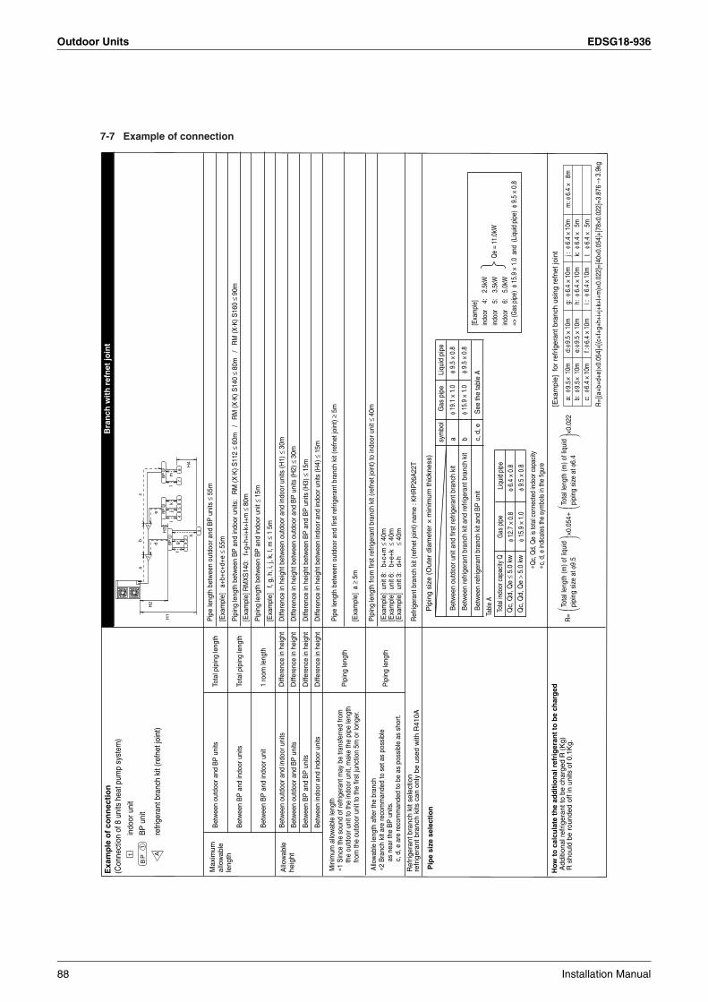
Outdoor Units EDSG18-936
7-7 Example of connection
Exa
mp
le o
f co
nn
ecti
on
(Con
nect
ion
of 8
uni
ts h
eat p
ump
syst
em)
Bra
nch
wit
h r
efn
et jo
int
Max
imum
al
low
able
le
ngth
Allo
wab
le le
ngth
afte
r the
bra
nch
∗2 B
ranc
h ki
t are
reco
mm
ande
d to
set
as
poss
ible
as
nea
r the
BP
uni
ts.
c, d
, e a
re re
com
man
ded
to b
e as
pos
sibl
e as
sho
rt.
Bet
wee
n in
door
and
indo
or u
nits
Bet
wee
n B
P a
nd B
P u
nits
Bet
wee
n ou
tdoo
r and
BP
uni
ts
Bet
wee
n ou
tdoo
r and
indo
or u
nits
Bet
wee
n B
P a
nd in
door
uni
t
Bet
wee
n B
P a
nd in
door
uni
ts
Bet
wee
n ou
tdoo
r and
BP
uni
ts
Pip
ing
leng
th
Pip
ing
leng
th
Diff
eren
ce in
hei
ght
Diff
eren
ce in
hei
ght
Diff
eren
ce in
hei
ght
Diff
eren
ce in
hei
ght
1 ro
om le
ngth
Tota
l pip
ing
leng
th
Tota
l pip
ing
leng
thP
ipe
leng
th b
etw
een
outd
oor a
nd B
P u
nits
≤55
m
Pip
e le
ngth
bet
wee
n ou
tdoo
r and
firs
t ref
riger
ant b
ranc
h ki
t (re
fnet
join
t) ≥
5m
[Exa
mpl
e] a
≥5m
Pip
ing
leng
th b
etw
een
BP
and
indo
or u
nits
: R
M (X
· K) S
112
≤60
m
/ R
M (X
· K) S
140
≤80
m
/ R
M (X
· K) S
160
≤90
m
[Exa
mpl
e]
a+b+
c+d+
e ≤
55m
Pip
ing
leng
th b
etw
een
BP
and
indo
or u
nit ≤
15m
[Exa
mpl
e]
f, g,
h, i
, j, k
, l, m
≤1
5m
Diff
eren
ce in
hei
ght b
etw
een
outd
oor a
nd in
door
uni
ts (H
1) ≤
30m
Diff
eren
ce in
hei
ght b
etw
een
outd
oor a
nd B
P u
nits
(H2)
≤30
m
Diff
eren
ce in
hei
ght b
etw
een
BP
and
BP
uni
ts (H
3) ≤
15m
Ref
riger
ant b
ranc
h ki
t (re
fnet
join
t) na
me
: KH
RP
26A
22T
Diff
eren
ce in
hei
ght b
etw
een
indo
or a
nd in
door
uni
ts (H
4) ≤
15m
Pip
ing
leng
th fr
om fi
rst r
efrig
eran
t bra
nch
kit (
refn
et jo
int)
to in
door
uni
t ≤40
m
[Exa
mpl
e] u
nit 8
: b
+c+m
≤40
m[E
xam
ple]
uni
t 6:
b+e
+k ≤
40m
[Exa
mpl
e] u
nit 3
: d
+h
≤
40m
[Exa
mpl
e] R
MX
S14
0:
f+g+
h+i+
k+l+
m ≤
80m
Allo
wab
le
heig
ht
Min
imum
allo
wab
le le
ngth
∗1 S
ince
the
soun
d of
refri
gera
nt m
ay b
e tra
nsfe
rred
from
th
e ou
tdoo
r uni
t to
the
indo
or u
nit,
mak
e th
e pi
pe le
ngth
fro
m th
e ou
tdoo
r uni
t to
the
first
junc
tion
5m o
r lon
ger.
Ref
riger
ant b
ranc
h ki
t sel
ectio
nre
frig
eran
t bra
nch
kits
can
onl
y be
use
d w
ith R
410A
Ho
w t
o c
alcu
late
th
e ad
dit
ion
al r
efri
ger
ant
to b
e ch
arg
edA
dditi
onal
ref
riger
ant t
o be
cha
rged
R (
Kg)
R s
houl
d be
rou
nded
off
in u
nits
of 0
.1K
g.
Pip
e si
ze s
elec
tio
n
φ 12.
7 ×
0.8
φ 15.
9 ×
1.0
φ 6.4
× 0
.8
φ 19.
1 ×
1.0
φ 15.
9 ×
1.0
φ 9.5
× 0
.8
φ 9.5
× 0
.8
φ 9.5
× 0
.8
Tabl
e A
∗Qc,
Qd,
Qe
is to
tal c
onne
cted
indo
or c
apac
ity
[Exa
mpl
e]in
door
4
: 2
.5kW
indo
or
5:
3.5
kWin
door
6
: 5
.0kW
=> (G
as p
ipe)
φ 1
5.9
× 1.
0 a
nd (
Liqu
id p
ipe)
φ 9
.5 ×
0.8
∗c, d
, e in
dica
tes
the
sym
bols
in th
e fig
ure
Gas
pip
eTo
tal in
door
cap
acity
QLi
quid
pip
eQ
c, Q
d, Q
e ≤
5.0
kw
Qc,
Qd,
Qe
> 5.
0 kw
P
ipin
g si
ze (
Out
er d
iam
eter
× m
inim
um th
ickn
ess)
R=
+To
tal l
engt
h (m
) of l
iqui
d pi
ping
siz
e at
φ6.
4
×0.0
22
R=[
(a+b
+d+e
)×0.
054]
+[(c
+f+g
+h+i
+j+k
+l+m
)×0.
022]
=[40
×0.0
54]+
[78×
0.02
2]=3
.876
→3.
9kg
×0.0
54To
tal l
engt
h (m
) of l
iqui
d pi
ping
siz
e at
φ9.
5
[Exa
mpl
e] f
or r
efrig
eran
t bra
nch
usin
g re
fnet
join
t
e:
9.5
6.4
× 10
mf :
×
10m
g:
16.4
× 1
0mh:
16
.4 ×
10m
i :
6.4
× 10
m
j :
16.4
× 1
0mk:
16
.4 ×
15m
a:
× 10
m9.
5 b:
×
10m
9.5
c:
06.4
× 1
0m
d:
9.5
× 10
m
l:6.
4 ×
5m
m:
6.4
×8m
Bet
wee
n re
frige
rant
bra
nch
kit a
nd B
P u
nit
Bet
wee
n re
frige
rant
bra
nch
kit a
nd re
frige
rant
bra
nch
kit
Bet
wee
n ou
tdoo
r uni
t and
firs
t ref
riger
ant b
ranc
h ki
tasy
mbo
lG
as p
ipe
Liqu
id p
ipe
b c, d
, eS
ee th
e ta
ble
A
indo
or u
nit
BP
uni
t
refri
gera
nt b
ranc
h ki
t (re
fnet
join
t)
Qe
= 11
.0kW
BP A1
1a
12
BP
BP
3
45
67
d
fg
h
ij
kl
m
e
bc
H1
H4
H2
H3
A
1
2B
P3
B
8
88 Installation Manual

EDSG18-936 Outdoor Units
3
7-8 Air tight test and vacuum dryingAfter doing the piping, perform the following inspections.
Be sure to use nitrogen gas. (See the figure (“Shutoff valve operation procedure”) for the location of the service port.)
[Procedure]Pressurize from the liquid pipes and gas pipes to 4.0 MPa (and not above 4.0 MPa). If there is not pressure drop over the next 24 hours, the equipment has passed the test.If the pressure drops, check for leakage positions. (Confirm that there is no leakage, then release nitrogen.)
Use a vacuum pump that can create a vacuum down to at least –100.7 kPa (5 Torr, –755 mmHg).
[Procedure]Operate the vacuum pump for at least 2 hours from both the liquid and gas pipes and decrease the pressure to at least –100.7 kPa. Leave at below –100.7 kPa for at least 1 hour and make sure that the vacuum gauge does not rise. (If it does rise, there is either still mois-ture in the system or a leak.)
Cases where moisture might enter the piping (i.e., if doing work during the rainy season, if the actual work takes long enough that condensation may form on the inside of the pipes, if rain might enter the pipes during work, etc.)After performing the vacuum drying for 2 hours, pressurize to 0.05 MPa (i.e., vacuum breakdown) with nitrogen gas, then depres-surize down to at least –100.7 kPa for an hour using the vacuum pump (vacuum drying). (If the pressure does not reach at least –100.7 kPa even after depressurizing for at least 2 hours, repeat the vacuum breakdown - vacuum drying process.) Leave as a vacuum for 1 hour after that, and make sure the vacuum gauge does not rise.
(Refer to figure 28)1. Nitrogen2. Decompression valve3. Vacuum pump4. Valve (Open)5. Charge hose6. Shutoff valve service port7. Indoor unit8. Gas line shutoff valve (Close)9. Liquid line shutoff valve (Close)
10. Indicates local procurement11. Outdoor unit12. BP unit
NoteThe shutoff valve must always be turned to “closed”. Otherwise the refrigerant in the outdoor unit will pour out.
• The names of parts needed to operate the shutoff valve are shown in the figure below. The unit is shipped from the factory with the shutoff valve turned to the “closed” position.
• Since the side boards may be deformed if only a torque wrench is used when loosening or tightening flare nuts, always lock the shutoff valve with a wrench and then use a torque wrench.
• In cases where the unit is run in heating mode when the outside temperature is low or in other situations where the operating pres-sure might drop, seal the gas-side flare nut on the shutoff valve with silicon sealant or the like to prevent it from freezing.
Shutoff valve operation procedureHave a hex wrench ready (size: 4 mm and 6 mm).
Opening the valve
1. Place the hex wrench on the valve bar and turn counter-clock-wise.
2. Stop when the valve bar no longer turns. It is now open.
Close the valve
1. Place the hex wrench on the valve bar and turn clockwise.2. Stop when the valve bar no longer turns. It is now closed.
• A seal is attached to the point indicated by the arrow.Take care not to damage it.
• Be sure to tighten the valve lid securely after operating the valves.
• Use a push-rod-provided charging hose for operation.• Be sure to tighten the valve lid securely after operation.
Tightening torque .......... 10.8 ~ 14.7 N·m
8. ADDITIONAL REFRIGERANT CHARGE
Warning
• When leaving the unit with the power on, be sure to switch with another person doing the installation or close the front panel.
Air tight test
Vacuum drying
Shutoff valve operation procedure
Precautions when handling the shutoff valve
Servicing port
Valve bar
Valve lid
Interunit piping connection
Precautions for handling valve lid
Liquid-side tightening torque Gas-side tightening torque
13.5 ~ 16.5 N·m 22.5 ~ 27.5 N·m
Precautions for handling servicing port
Silicon sealing pad
(Make sure that there is no gap)
Direction to open Direction to open
<Gas pipe><Liquid pipe>
Valve lid
Shutoff valve (lid attachment)
Installation Manual 89
Outdoor Units EDSG18-936
8-1 Before adding refrigerant• Make sure the following work and inspection is complete, in
accordance with the installation manual.• Piping• Wiring• Airtightness test, Vacuum drying
8-2 Checking the refrigerant tank• Check whether the tank has a siphon pipe before charging and
place the tank so that the refrigerant is charged in liquid form. (See the figure below.)
8-3 Adding refrigerant
9. POST-WORK CHECKSPerform the following checks after work is complete.(1) Drain pipe connection, removal of transport clasp →
See “5. PRECAUTIONS ON INSTALLATION”. (2) Incorrect power supply wiring, loose screws →
See “6-3 How to connect the power supply wiring”.(3) Incorrect interunit wiring, loose screws →
See “6-4 Interunit wiring connection procedure”.(4) Incorrect refrigerant piping connections →
See “7. PRECAUTIONS ON REFRIGERANT PIPING”.(5) Piping sizes, use of insulation →
See : “7-2 Selecting piping material”.“7-6 Heat insulation of piping”.
(6) Shutoff valve check →Make sure both the liquid-side and gas-side shutoff valves are open.
(7) Record of Amount of Refrigerant Added →Record it on “Record of Amount of Refrigerant Added” on the “Service Precautions” plate.
(8) Measuring the insulation of the main power circuit →• Use a 500V mega-tester. • Do not use the mega-tester for weak currents other than 220-
240V. (Interunit wiring)
Caution
To the pipe-layerAfter completing installation, be sure to open the valve.(Operating the unit with the valve shut will break the compressor.)
10. TEST RUNThis unit is equipped with a crank case heater to ensure smooth startup. Be sure to turn the power on at least 6 hours before operation in order to have power running to the crank case heater.
Warning
When leaving the unit with the power on, be sure to switch with another person doing the installation or close the front panel.
Precautions before turning the power on• Using insulating sheets, tape electric parts as described in the
“Service Precautions” plate on the back of the front panel.• All indoor units connected to the outdoor unit operate automati-
cally. Complete work on the indoor units in order to ensure maximum safety.
10-1 Power On–Check Operation• Make sure to perform the check operation after installation.
(If the air conditioner is operated using the indoor remote control-ler without performing the check operation, the malfunction code “U3” is displayed in the indoor remote controller, and normal oper-ation is disabled.)
• When making settings on the outdoor unit PC board (A2P) after turning the power on, do not touch anything other than the push-button switches and dip switches. (See the “Service Precautions” plate for the locations of the push-button switches (BS1-5) and dip switches (D1-1, 2) on the PC board (A2P).)
Tank with siphon pipe Other tanks
There is a siphon pipe inside, so the cylinder need not be upside-down to fill with liquid.(Stand the cylinder upright when filling.)
Stand the tank upside down and charge.
1. Calculate the amount of refrigerant to add as described in “Calculating the amount of refrigerant to add” in “7. PRECAUTIONS ON REFRIGERANT PIPING”.
2. After the vacuum drying is finished, open valve A and charge the calculated amount of refrigerant through the service port for the liquid-side shutoff valve.
3. Close valve A after charging is complete.Note: If all the refrigerant to be added cannot be charged using the above procedure, right-hand the procedure
below and re-charge the refrigerant.
If all the refrigerant could not be addedAdd refrigerant using the following procedure. See the “Service Precautions” plate attached to the control box lid on the outdoor unit for details on the settings for adding refrigerant.[Procedure]1. Close the front panel and turn on the power to all outdoor units and indoor units in the refrigeration system.2. Open the gas and liquid-side shutoff valves all the way and add the refrigerant. (Open valve A immediately after starting the compressor.)3. Once the appropriate amount of refrigerant is in, press the confirmation button (BS3) on the outdoor unit PC
board (A2P), and stop operation after adding the refrigerant.4. Close valve A after charging is complete.
Filling after calculating the amount of refrigerant to add
• See “Shutoff valve operation procedure” in “7. PRECAUTIONS ON REFRIGERANT PIPING” for details on how to use the shutoff valve.• Connect the service port (for charging refrigerant) inside the unit. When the unit is shipped from the factory,
refrigerant is already charged, so be careful when connecting the charge hose.• After adding the refrigerant, do not forget to close the lid of the service port (for adding refrigerant).
The tightening torque of the lid is 11.5 – 13.9 N/m.(Refer to figure 30)1. Gas line shutoff valve 2. Liquid line shutoff valve 3. Shutoff valve service port4. BP unit 5. Measuring instrument 6. R410A Tank (Siphon system)7. Valve A 8. Service port 9. (For adding refrigerant)10. Outdoor unit
Status of the shutoff valve and other valves when adding refrigerant operation
State of valve A and the shutoff valve Valve A Liquid line shutoff valve
Gas line shutoff valve
CloseOpen Open Open
Open OpenBefore starting to charge the refrigerantDuring charging of the refrigerant
• See “Shutoff valve operation procedure” in “7. PRECAUTIONS ON REFRIGERANT PIPING” fordetails on how to use the shutoff valve.(Refer to figure 29)
1. R410A Tank (Siphon system) 5. Shutoff valve service port 2. Measuring instrument 6. Gas line shutoff valve 3. Valve A 7. Outdoor unit 4. BP unit 8. Liquid line shutoff valve
Status of the shutoff valve and other valves when adding refrigerant
State of valve A and the shutoff valve Valve A Liquid line shutoff valve
Gas line shutoff valve
Close Close CloseClose CloseOpen
Before starting to charge the refrigerantDuring charging of the refrigerant
90 Installation Manual

EDSG18-936 Outdoor Units
3
• During the operation, monitor the outdoor unit operation status and check for any incorrect wiring.
<Precautions During Check Operation>• If operation is performed within 12 minutes of BP units and
outdoor units being turned on, H2P will light up, and the compressor will not run.Only perform operation after checking that the LED display is as shown in “10-1 Power On–Check Operation” 2. table.
• In order to ensure uniform refrigerant distribution, it may take up to around 10 minutes for the compressor to start up after the unit begins running. This is not a malfunction.
• Each indoor unit cannot be checked individually for problems.After this operation is complete, run the unit normally using the remote controller.
• The check run cannot be performed in recovery or other modes.• If the outlet pipe thermistor (R2T), the intake pipe thermistor
(R3T), and the pressure sensors (S1NPH and S1NPL) are removed before operation, the compressor might burn out, so avoid this under all circumstances.
10-2 Temperature control operation checklist
• After check operation is complete, checking the temperature con-trol using normal operation.(Heating is not possible if the outdoor temperature is 24˚C or higher. See the included operation manual.)(1) Make sure the indoor and outdoor units are operating nor-
mally.(If liquid compression by the compressor or other abnormal noises can be heard, stop the unit immediately, heat the crank case for a sufficient amount of time, and try again.)
(2) Run each indoor unit one at a time and make sure the corre-sponding outdoor unit is also running.
(3) Check to see if cold (or hot) air is coming out of the indoor unit.
(4) Press the fan direction and fan strength buttons on the indoor unit to see if they operate properly.
<Precautions during temperature control checks>• For around 5 minutes after the compressor stops, the compressor
will not run even if the “operate/stop” button on the remote control-ler is pressed.
• When the system operation is stopped by the remote controller, the outdoor units may continue operating for further 1 minutes at maximum.
• Malfunction code “U3” is displayed if check operation is not per-formed using the test run button the first time after installation. Perform the check operation in accordance with “10-1 Power On–Check Operation”.
1. Close the outdoor unit’s front panel.Turn the power on for the outdoor unit and the BP unit.
2. • Open the outdoor unit’s front panel.• Make sure the LED display on the outdoor unit’s PC boards (A1P and
A2P) are as shown in the following chart.
LED display (Default status before delivery)
SEVICE MONITOR MODE
HAP
A1P A2P
H1P H2P H3P H4P H5P H6P H7P
TEST/HWL
IND MASTER SLAVE L.N.O.P DEMAND
6. Close the outer panel of the outdoor unit after check operation is complete.
Do not leave any shutoff valve closed otherwise the compressor will fail.
Caution
Be sure to turn the power on at least 6 hours before operation in order to have power running to the crank case heater.
To avoid the risk of electric shock, do not touch anything other than the push-button switches on the PC board (A2P) when making settings.
Caution
LED display: OFF ON Blinking
Use caution to avoid electric shock while working, since the outdoor unit is on.
• Only set the push-button switches (BS1-5) after making sure the microcomputer OK monitor is lit up.
• See the “Service Precautions” plate on the front panel of the outdoor unit for details on how to make the settings. (Do not forget to write the settings down on the “Service Precautions” plate.)
• The dip switch (DS1-1) does not need to be set, so do not touch it. Doing so may cause malfunction.
• If you have to leave the outdoor unit during check operation, either switch with another worker or close the front panel.
• The system operates for about 30 minutes (60 minutes at maximum) and automatically stops the check operation.
• The system can start normal operation about 3 minutes after the check operation if the remote controller does not display any error code.
3. • When the customer requestsquiet operation or demandoperation, make these settingsusing the push-button switches(BS1-5) on the outdoor unit’sPC board (A2P).
• Operate the push-buttonswitches through the openingafter protecting it with aninsulation cover. (See the “Service Precautions”plate for details.)
4. • Check that the liquid and gas-sideshutoff valves are open, and ifthey are closed, open them.
5. Press the test run button (BS4) forat least five seconds and performcheck operation. For details, see “How to performcheck operation” on the “ServicePrecautions” plate.
Installation Manual 91
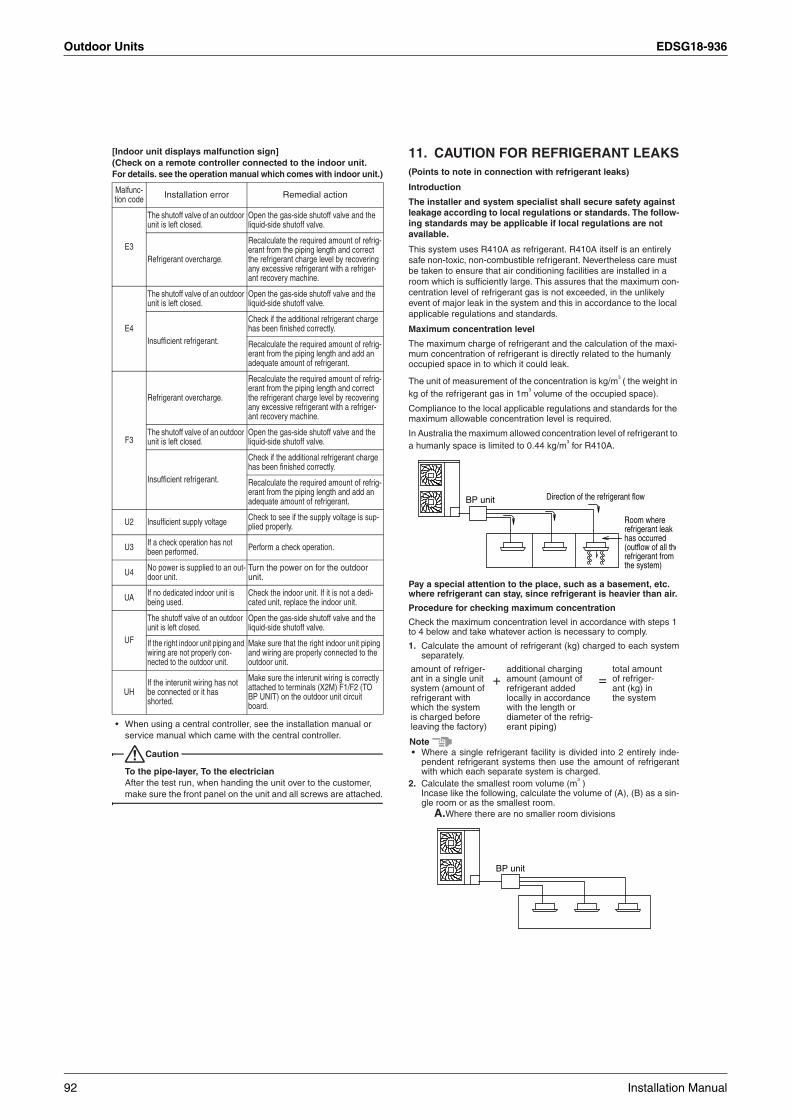
Outdoor Units EDSG18-936
[Indoor unit displays malfunction sign](Check on a remote controller connected to the indoor unit. For details. see the operation manual which comes with indoor unit.)
• When using a central controller, see the installation manual or service manual which came with the central controller.
Caution
To the pipe-layer, To the electricianAfter the test run, when handing the unit over to the customer, make sure the front panel on the unit and all screws are attached.
11. CAUTION FOR REFRIGERANT LEAKS(Points to note in connection with refrigerant leaks)
Introduction
The installer and system specialist shall secure safety against leakage according to local regulations or standards. The follow-ing standards may be applicable if local regulations are not available.
This system uses R410A as refrigerant. R410A itself is an entirely safe non-toxic, non-combustible refrigerant. Nevertheless care must be taken to ensure that air conditioning facilities are installed in a room which is sufficiently large. This assures that the maximum con-centration level of refrigerant gas is not exceeded, in the unlikely event of major leak in the system and this in accordance to the local applicable regulations and standards.
Maximum concentration level
The maximum charge of refrigerant and the calculation of the maxi-mum concentration of refrigerant is directly related to the humanly occupied space in to which it could leak.
The unit of measurement of the concentration is kg/m3 ( the weight in
kg of the refrigerant gas in 1m3 volume of the occupied space).
Compliance to the local applicable regulations and standards for the maximum allowable concentration level is required.
In Australia the maximum allowed concentration level of refrigerant to a humanly space is limited to 0.44 kg/m
3 for R410A.
Pay a special attention to the place, such as a basement, etc. where refrigerant can stay, since refrigerant is heavier than air.
Procedure for checking maximum concentration
Check the maximum concentration level in accordance with steps 1 to 4 below and take whatever action is necessary to comply.
1. Calculate the amount of refrigerant (kg) charged to each systemseparately.
Note• Where a single refrigerant facility is divided into 2 entirely inde-
pendent refrigerant systems then use the amount of refrigerantwith which each separate system is charged.
2. Calculate the smallest room volume (m3 )
Incase like the following, calculate the volume of (A), (B) as a sin-gle room or as the smallest room.
A.Where there are no smaller room divisions
Malfunc-tion code Installation error Remedial action
E3
The shutoff valve of an outdoor unit is left closed.
Open the gas-side shutoff valve and the liquid-side shutoff valve.
Refrigerant overcharge.
Recalculate the required amount of refrig-erant from the piping length and correct the refrigerant charge level by recovering any excessive refrigerant with a refriger-ant recovery machine.
E4
The shutoff valve of an outdoor unit is left closed.
Open the gas-side shutoff valve and the liquid-side shutoff valve.
Insufficient refrigerant.
Check if the additional refrigerant charge has been finished correctly.
Recalculate the required amount of refrig-erant from the piping length and add an adequate amount of refrigerant.
F3
Refrigerant overcharge.
Recalculate the required amount of refrig-erant from the piping length and correct the refrigerant charge level by recovering any excessive refrigerant with a refriger-ant recovery machine.
The shutoff valve of an outdoor unit is left closed.
Open the gas-side shutoff valve and the liquid-side shutoff valve.
Insufficient refrigerant.
Check if the additional refrigerant charge has been finished correctly.
Recalculate the required amount of refrig-erant from the piping length and add an adequate amount of refrigerant.
U2 Insufficient supply voltage Check to see if the supply voltage is sup-plied properly.
U3 If a check operation has not been performed. Perform a check operation.
U4 No power is supplied to an out-door unit.
Turn the power on for the outdoor unit.
UA If no dedicated indoor unit is being used.
Check the indoor unit. If it is not a dedi-cated unit, replace the indoor unit.
UF
The shutoff valve of an outdoor unit is left closed.
Open the gas-side shutoff valve and the liquid-side shutoff valve.
If the right indoor unit piping and wiring are not properly con-nected to the outdoor unit.
Make sure that the right indoor unit piping and wiring are properly connected to the outdoor unit.
UHIf the interunit wiring has not be connected or it has shorted.
Make sure the interunit wiring is correctly attached to terminals (X2M) F1/F2 (TO BP UNIT) on the outdoor unit circuit board.
amount of refriger-ant in a single unit system (amount of refrigerant with which the system is charged before leaving the factory)
+additional charging amount (amount of refrigerant added locally in accordance with the length or diameter of the refrig-erant piping)
=total amount of refriger-ant (kg) in the system
Direction of the refrigerant flowBP unit
Room where refrigerant leak has occurred (outflow of all therefrigerant from the system)
BP unit
92 Installation Manual

EDSG18-936 Outdoor Units
3
B.Where there is a room division but there is an openingbetween the rooms sufficiently large to permit a free flow ofair back and forth.
(Where there is an opening without a door or where there areopenings above and below the door which are each equivalent insize to 0.15% or more of the floor area.)
3. Calculating the refrigerant density using the results of the calcu-lations in steps 1 and 2 above.
If the result of the above calculation exceeds the maximum con-centration level then make similar calculations for the second thenthird smallest room and so until the result falls short of the maxi-mum concentration.
4. Dealing with the situations where the result exceeds the maxi-mum concentration level.Where the installation of a facility results in a concentration inexcess of the maximum concentration level then it will be neces-sary to revise the system. Please consult your Daikin supplier.
total volume of refrigerant in the refrigerant system ≤ maximum concen-
tration level (kg/m3)size (m
3 ) of smallest room in which
there is an indoor unit installed
Opening between roomsPartition
BP unit
C : 3PN07193-3E
Installation Manual 93

Outdoor Units EDSG18-936
1.2 Service Precautions
Cautions on ServiceCool/heat selector connection procedure
Cover electric parts with an insulating sheet during inspection to prevent electric shock.
Reactor
Set mode 1 Set mode 2
Page
H1PTurn off Turn on
Curing range
Page
H1P
BS1
MODE SET RETURN TEST RESET
BS2 BS3 BS4 BS5DS1
ON
1 2OFF
H2P H3P H4P H5P H6P H7P
Lownoise Demand
Test Changeover between cooling and heating
Error Individual Batch(slave)
Batch(master)
Control box
LED indicator status
Changing the set mode The set mode can be changed as follows using the MODE button (BS1).
Turn off Turn on Flicker Turn on or off
A B C
A B C
A4PA2P
DIP switches (DS1-1 and DS1-2)
Cool/heatselector
DS1-1switch knob
TU
ONI
FFO/
NO
A2P
A1P
A4P
X2M
HAPX1M
Set the remote controller only when changing over the operation mode between cooling and heating using the remote controller installed in the outdoor. Connect the cool/heat selector (optional accessory) to the terminals (A, B and C) on the outdoor PC board (A4P).Set the cool/heat selector switch DS1-1 from “IN (inside) ” (which is selected at the factory before shipment) to “OUT (outside) ”.
DS1 1 2
C/HSELECTOR
If you are unsure during setting, press the MODE button (BS1). Set mode 1 (H1P: Turn off) is selected again.
When performing low noise operation or demand operation using an external command or setting cooling or heating using the cool/heat centralized remote controller, the outdoor unit external control adaptor (optional accessory) is required. For the details, refer to the manual attached to the adaptor.
Cover this range with an insulating sheet and fix the sheet with tape.
Sets the address again when the wiring is changed or an indoor unit is added.Performs the test run.Used at field set.Changes the set mode.
Press and hold the MODE button (BS1)for 5 seconds or more.
While the LED indicator H1P is flickering ( ), set mode 1 is selected when the MODE button (BS1) is pressed once.
Press the MODE button (BS1) once.
Page
H1P
Caution
(The LED indicator status shown at left indicates the status at factory set.)
Cautions on inspecting the control box for service
Warning Caution: Electric shock
1. Before starting the service inspection, confirm using the tester that the power is shut down in the power terminal block (X1M).
2. Avoid contact with the hot area.Some portions are extremely hot in electric parts and the inside.
3. Avoid contact with the charged area. Never touch the charged area before confirming that the residual voltage is 50 V or less. 1 Shut down the power, and then leave the control box for 10 minutes. 2 Make sure to touch the earth terminal to release the static electricity from
your body (to prevent failure of the PC board). 3 Measure the residual voltage in the specified measurement position using
the tester while paying attention not to touch the charged area. 4 Immediately after measuring the residual voltage, disconnect the connectors of
the outdoor unit fan motor. (If the fan rotates by strong wind blowing against it, the capacitor will be charged, causes the danger of electric shock.)
After finishing the inspection, re-connect the connectors of the outdoor unit fan motor.
Outdoor unit fan connectors
Control boxCapacitor (C4)
Side Side
Symbolon side
Residual voltage measurementposition
Front
A1P
A1P
A1P
C4A2PA4PX2M
X1M
X106A X107A
94 Installation Manual

EDSG18-936 Outdoor Units
3
Setting (cooling/heating selection) in set mode 1 (H1P: Turn off)
Setting in set mode 2 (H1P: Turn on)
Checking the set items
Setting procedure
Setting procedure Contents of setting
For the contents marked with “ ”, the outdoor unit external control adaptor (optional accessory) is required. For the details, refer to the manual attached to the adaptor.
For any setting other than the above cases, refer to the Service Manual.
The following contents can be set in set mode 1 .
The following contents A to G can be set.
Contents of cooling/heating selection
Press the SET button (BS2), and select either LED indicator status shown at right.
Press the SET button (BS2), and select either LED indicator status shown at right in accordance with the contents of setting ( A to G ).
Contents of each settingIn the case of A or B … ON/OFFIn the case of FIn the case of C … OFF/mode 1 to mode 3In the case of D or F … Mode 1 to mode 3Press the SET button (BS2) , and select either LED indicator status shown at right in accordance with the above case.In C and D , noise is smallest in mode 3, and largest in mode 1.In E , the power consumption is smallest in mode 3, and largest in mode 1.(For the details, refer to the Service Manual.)
Press the RETURN button (BS3) to display the currently selected setting. (Refer to 3 .)
Press the RETURN button (BS3) to determine the setting. (The LED indicator status changes from “flicker” to “turn on”.)
Press the RETURN button (BS3) again to start the operation in accordance with the setting.
Press the RETURN button (BS3) to determine the setting.
When cooling or heating is selected individually in each outdoor unit system (at factory set)
When cooling or heating is selected for all outdoor unit systems (master unit)
When cooling or heating is selected for all outdoor unit systems (slave unit)
A Refrigerant additional charging operation
B Refrigerant recovery/evacuation mode
C Automatic low noise setting at night
D External low noise level setting
E Demand level setting
F External low noise demand absence/presence setting
ON
OFF (at factory set)
OFF (at factory set)
Mode 1
Mode 2
Mode 3
Mode 1
Mode 2 (at factory set)
Mode 3
Check item
Current operation status
Cooling/heating
selection
Low noise operation status
Demand operation status
LED indicator status example
Normal status Error status During preparation or check operation When cooling or heating is selected individually in each outdoor unit system (at factory set)
When cooling or heating is selected for all outdoor unit systems (master unit)
When cooling or heating is selected for all outdoor unit systems (slave unit)
During normal operation (at factory set) During low noise operation
During normal operation (at factory set) During demand operation
LED indicator status and positionH1P H2P H3P H4P H5P H6P H7P
LED indicator status and positionH1P H2P H3P H4P H5P H6P H7P
LED indicator status and positionH1P H2P H3P H4P H5P H6P H7P
A BF
C
D E
Installation Manual 95
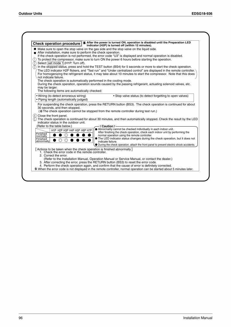
Outdoor Units EDSG18-936
H1P H2P H3P H4P H5P H6P H7PFinishednormallyFinishedabnormally
Make sure to open the stop valve on the gas side and the stop valve on the liquid side. After installation, make sure to perform the check operation.If the check operation is not performed, the error code “U3” is displayed and normal operation is disabled.
The LED indicator H2P flickers, and “Test run” and “Under centralized control” are displayed in the remote controller.For homogenizing the refrigerant status, it may take about 10 minutes to start the compressor. Note that this does not indicate failure.The check operation is automatically performed in the cooling mode.During the check operation, operation sounds caused by the passing refrigerant, actuating solenoid valves, etc. may be larger.The following items are automatically checked:
For suspending the check operation, press the RETURN button (BS3). The check operation is continued for about 30 seconds, and then stopped. ( The check operation cannot be stopped from the remote controller during test run.)
To protect the compressor, make sure to turn ON the power 6 hours before starting the operation.Select set mode 1 (H1P: Turn off).In the stopped status, press and hold the TEST button (BS4) for 5 seconds or more to start the check operation.
Close the front panel.The check operation is continued for about 30 minutes, and then automatically stopped. Check the result by the LED indicator status in the outdoor unit.
1. Check the error code in the remote controller. 2. Correct the error.
(Refer to the Installation Manual, Operation Manual or Service Manual, or contact the dealer.)3. After correcting the error, press the RETURN button (BS3) to reset the error code. 4. Perform the check operation again, and confirm that the cause of error is definitely corrected.
Abnormality cannot be checked individually in each indoor unit.After finishing the check operation, check each indoor unit by performing the normal operation using the remote controller.The LED indicator status changes during the check operation, but it does not indicate failure.During the check operation, attach the front panel to prevent electric shock accidents.
Caution
Check operation procedure After the power is turned ON, operation is disabled until the Preparation LED indicator (H2P) is turned off (within 12 minutes).
• Wiring (to detect erroneous wiring) • Stop valve status (to detect forgetting to open valves)• Piping length (automatically judged)
(Refer to the table below.)
Actions to be taken when the check operation is finished abnormally
When the error code is not displayed in the remote controller, normal operation can be started about 5 minutes later.
96 Installation Manual

EDSG18-936 Outdoor Units
3
(The internal evacuation is not required during initial installation. It is required during service.)
In the stopped status, select set mode 2 , and set to ON the refrigerant recovery/evacuation mode B .(Do not reset set mode 2 until evacuation is completed.) “Test run” and “Under centralized control” are displayed in the remote controller, and alloperations are disabled.
Evacuate the unit using the vacuum pump.Press the MODE button (BS1) to reset set mode 2 .
In the stopped status, select set mode 2 , and set to ON the refrigerant recovery/evacuation mode B .All expansion valves are completely opened and some solenoid valves are turned ON in the indoor unit and outdoor unit.“Test run” and “Under centralized control” are displayed in the remote controller, and all operations are disabled.
Recover the refrigerant using the refrigerant recovery device.(Recover the refrigerant in conformance to the laws and regulations of the local site.) Press the MODE button (BS1) to reset set mode 2 .
Never turn OFF the power of the outdoor unit while the refrigerant is being recovered. (If the power is turned OFF, the solenoid valves are closed, and the refrigerant cannot be recovered from the outdoor unit.)
Service mode operation procedure
Internal evacuation procedure
Refrigerant recovery procedure using the refrigerant recovery device
The service mode cannot start until the LED indicator H2P is turned off (within 12 minutes) after the power is turned ON.
Caution
Service portfor additionally
charging the refrigerant
Refrigerant additional charging operation procedureWhen the outdoor unit is stopped and the entire quantity of refrigerant cannot be charged from the stop valve on the liquid side, make sure to charge the remaining quantity of refrigerant using this procedure. If the refrigerant quantity is insufficient, the unit may malfunction.
Turn ON the power of the indoor unit and the outdoor unit. Make sure to completely open the stop valve on the gas side and the stop valve on the liquid side.Connect the refrigerant charge hose to the service port (for additionally charging the refrigerant).In the stopped status, set to ON the refrigerant additional charging operation A inset mode 2 (H1P: Turn on).The operation is automatically started. (The LED indicator H2P flickers, and “Test run” and “Under centralized control” are displayed in the remote controller.) After charging the specified quantity of refrigerant, press the RETURN button (BS3) to stop the operation.
The operation is automatically stopped within 30 minutes.If charging is not completed within 30 minutes, set and perform the refrigerant additional charging operation A again.If the refrigerant additional charging operation is stopped soon, the refrigerant may be overcharged.Never charge extra refrigerant.
Disconnect the refrigerant charge hose.
When setting C to E in set mode 2 , circle to record the setting contents in the right table.
Calculate the required refrigerant quantity to be charged using the following procedure.
C Automatic low noise setting at night
OFF • Mode 1 • Mode 2 • Mode 3
D External low noise setting
Mode 1 • Mode 2 • Mode 3
E Demand level setting
Mode 1 • Mode 2 • Mode 3
Additional charge quantity Liquid pipe lengthLiquid pipe size 9.5 X 0.054
No.ModelnameInstallationplace
(Make sure to record the contents of setting, because they are required in after-sales service.)
1. Recording the contents of various setting
2. Recording the additionally charged refrigerant quantity
3. Recording the indoor unit model names and installation places
kg X 0.054(m)
Liquid pipe lengthLiquid pipe size 6.4 X 0.022
X 0.022(m)
1 2 3 4 5 6 7 8 9
2PN07176-1C
Installation Manual 97
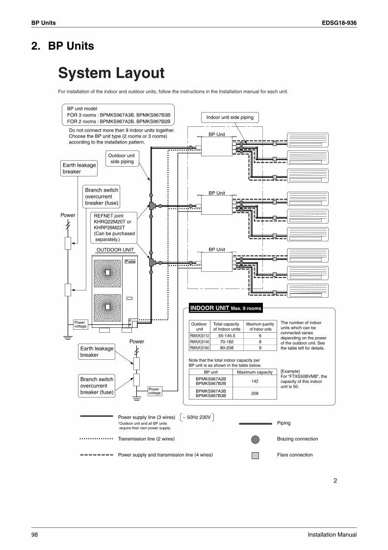
BP Units EDSG18-936
2. BP Units
2
System LayoutFor installation of the indoor and outdoor units, follow the instructions in the Installation manual for each unit.
Power voltage
Power voltage
BP unit modelFOR 3 rooms : BPMKS967A3B, BPMKS967B3BFOR 2 rooms : BPMKS967A2B, BPMKS967B2B
Do not connect more than 9 indoor units together. Choose the BP unit type (2 rooms or 3 rooms) according to the installation pattern.
Power
Power
BP Unit
BP Unit
BP Unit
Flare connection
OUTDOOR UNIT
REFNET jointKHRQ22M20T or KHRP26M22T(Can be purchased separately.)
Earth leakage breaker
Branch switch overcurrent breaker (fuse)
Earth leakage breaker
Branch switch overcurrent breaker (fuse)
Power supply line (3 wires) ~ 50Hz 230V
Transmission line (2 wires)
Power supply and transmission line (4 wires)
Piping
Brazing connection
Outdoor unit
Total capacity of Indoor units
Maximum quantity of Indoor units
RMX(K)S112 55-145.5 6RMX(K)S140 70-182 8RMX(K)S160 80-208 9
BP unit Maximum capacity
BPMKS967A2B 142BPMKS967B2B
BPMKS967A3B 208BPMKS967B3B
The number of indoor units which can be connected varies depending on the power of the outdoor unit. See the table left for details.
[Example]For “FTXS50BVMB”, the capacity of this indoor unit is 50.
INDOOR UNIT Max. 9 rooms
Indoor unit side piping
Outdoor unit side piping
Note that the total indoor capacity per BP unit is as shown in the table below.
*Outdoor unit and all BP units require their own power supply.
98 Installation Manual

EDSG18-936 BP Units
3
3
Accessories
Items to be prepared in the field• Connecting wires between BP unit and indoor unit (H05VV(*), 4 wires, 1.6mm or 2.0mm)• Connecting wires (H05VV(*), 3 wires, 1.6mm or 2.0mm)• Transmission wires (H05VV(*), 2 wires, 0.75mm² to 1.25mm²)• Installation parts (hanging bolts: 4 × M10 or M8; nuts: 8; flat washers: 8)• Screws for wall-mounting: 6 × M5• Heat insulation (joint) [Thermal conductivity: 0.041 - 0.052W/mK (0.035 - 0.045kcal/mh˚C) / thickness 13mm
(1/2 inch) or more / Heat resistance: 100˚C or higher]
(*) Only in protected pipes, use H07RN-F when protected pipes are not use. Specifications for local wiring power cord and branch wiring are in compliance with IEC60245.
Precautions for Selecting the LocationThe BP unit is for indoor use.Install in a location such as above a ceiling or behind a wall in accordance with the following conditions:
• That the unit is fully supported, and is in a location with little or no vibration.• That the refrigerant pipes for the indoor and outdoor units can be repaired with ease, and that the units are placed well within
the distance from each other allowed by the pipe length.• That there is nothing nearby that produces heat or steam (gas).• When installing, that there is enough room for servicing the unit.• Do not install in location that is hot or humid for long periods of time.
A location where the dry-bulb (DB) temperature around the BP unit reaches 60˚C or higher.• A well-ventilated area.• Do not install near bedrooms. The sound of refrigerant flowing through the piping may sometimes be audible.
For restrictions on installation, refer to P5~6. “Installation”.
Installation Manual
1pc.
For indoor unit side piping (gas) (pipe joint)
BPMKS967A3B BPMKS967B3B(For 3 rooms)
: 3pcs.BPMKS967A2B BPMKS967B2B(For 2 rooms)
: 2pcs.
For outdoor unit side piping (gas) (pipe joint)
1pc.
Hanger metal
4pcs.
For outdoor unit side piping (gas) (pipe joint)
1pc.
Screws
8pcs.
For outdoor unit side piping (liquid) (pipe joint)
1pc.
Binding band
2pcs.
For Mindoor unit side piping (liquid) (pipe joint)
1pc.
Heat insulation (2pcs. is 1set)
BPMKS967A3B BPMKS967B3B(For 3 rooms)
: 4setsBPMKS967A2B BPMKS967B2B(For 2 rooms)
: 3sets
16
27
38
49
5 10
Installation Manual 99
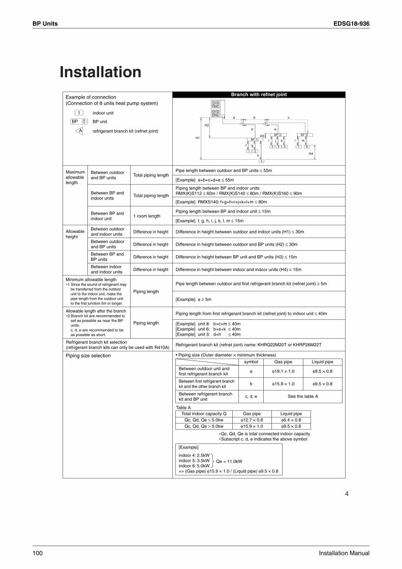
BP Units EDSG18-936
4
Installation
Piping length
Piping length
Pipe length between outdoor and first refrigerant branch kit (refnet joint) ≥ 5m
[Example] a ≥ 5m
[Example] unit 8: b+c+m ≤ 40m[Example] unit 6: b+e+k ≤ 40m[Example] unit 3: d+h ≤ 40m
Piping length from first refrigerant branch kit (refnet joint) to indoor unit ≤ 40m
Minimum allowable length∗1 Since the sound of refrigerant may
be transferred from the outdoor unit to the indoor unit, make the pipe length from the outdoor unit to the first junction 5m or longer.
Allowable length after the branch∗2 Branch kit are recommended to
set as possible as near the BP units. c, d, e are recommended to be as possible as short.
Example of connection(Connection of 8 units heat pump system)
indoor unit
BP unit
refrigerant branch kit (refnet joint)
Branch with refnet joint
Pipe length between outdoor and BP units ≤ 55m
[Example] a+b+c+d+e ≤ 55m
Piping length between BP and indoor units: RMX(K)S112 ≤ 60m / RMX(K)S140 ≤ 80m / RMX(K)S160 ≤ 90m
[Example] RMXS140: f+g+h+i+j+k+l+m ≤ 80m
Piping length between BP and indoor unit ≤ 15m
[Example] f, g, h, i, j, k, l, m ≤ 15m
Difference in height between outdoor and indoor units (H1) ≤ 30m
Difference in height between outdoor and BP units (H2) ≤ 30m
Difference in height between BP unit and BP units (H3) ≤ 15m
Difference in height between indoor and indoor units (H4) ≤ 15m
Refrigerant branch kit (refnet joint) name: KHRQ22M20T or KHRP26M22T
Maximum allowable length
Between indoor and indoor units
Between BP and BP units
Between outdoor and BP units
Between outdoor and indoor units
Between BP and indoor unit
Between BP and indoor units
Between outdoor and BP units
Difference in height
Difference in height
Difference in height
Difference in height
1 room length
Total piping length
Total piping length
Allowable height
Refrigerant branch kit selection (refrigerant branch kits can only be used with R410A)
Piping size selection
a
1 2
BP
BP
3
4 5 6 7
d
f g
h
i j k l m
e
b c
H1
H4
H2
H3
A
1
2 BP 3
B
8
1
A
BP 1
[Example]
indoor 4: 2.5kWindoor 5: 3.5kWindoor 6: 5.0kW=> (Gas pipe) φ15.9 × 1.0 / (Liquid pipe) φ9.5 × 0.8
Qe = 11.0kW
• Piping size (Outer diameter × minimum thickness)
Between refrigerant branch kit and BP unit
Between first refrigerant branch kit and the other branch kit
Between outdoor unit and first refrigerant branch kit
symbol
a
b
c, d, e
Gas pipe Liquid pipe
φ19.1 × 1.0
φ15.9 × 1.0
φ9.5 × 0.8
φ9.5 × 0.8
See the table A
Total indoor capacity QQc, Qd, Qe ≤ 5.0kwQc, Qd, Qe > 5.0kw
Gas pipe Liquid pipeφ12.7 × 0.8φ15.9 × 1.0
φ6.4 × 0.8φ9.5 × 0.8
Table A
∗Qc, Qd, Qe is total connected indoor capacity∗Subscript c, d, e indicates the above symbol
100 Installation Manual

EDSG18-936 BP Units
3
5
Installation• This unit may be installed suspended from the ceiling or mounted on the wall.• This unit may only be installed, as shown in the diagram below. (The side should be facing upwards.)
However, it may be freely installed in any direction forward or back, and to the sides.• Be sure to leave a 650mm square opening for service and inspection as shown in the diagram below, for both ceiling-
suspended installation and wall-mounted installation.• This unit “does not require drain treatment”.• This unit may be installed with sides or facing forward (servicing direction).• The piping for the indoor unit may be freely led around in directions , , or .• The inclination of side must be within ±5 degrees forward or back or to the sides.
Cut line for I.D. φ15.9
I.D. φ19.1
(product dimensions and attachment bolt pitch)
(Servicing space)Min 390
(Servicing space)Min 390
(Ser
vici
ng s
pace
)M
in 3
00
Installation restrictions(Installation and service space)
Standard accessories
( 25)
113
Wall-mounted
16368
110
45
O.D. φ19.1Dimple
65110
165 90
90
100
I.D. φ12.7
I.D. φ9.5I.D. φ6.4
O.D. φ15.9
Cut line for O.D. φ6.4
O.D. φ9.5
150
For indoor unit side (Gas)
For outdoor unit side (Liquid)
For outdoor unit side (Gas)
For outdoor unit side (Gas) For indoor unit side (Liquid)
Servicing is needed opening of 650mm square for service and maintenance.
The opening for Inspection
4557 95
(304)2×2-Brazing
73.5 (1
80)
23
Room
A
Room
B
INDOOR UNIT SIDE OUTDOOR UNIT SIDE
Wiring clamp
(650)294 178
1972-Brazing
107
322
254
(304
)
25
73.5
178
2-I.D. φ15.9 CuT
2-I.D. φ6.4 CuT
I.D. φ9.5 CuT
I.D. φ19.1 CuT
Terminal (For A room)Terminal (For B room)
Terminal (For transmission)
Earth (M4) Earth (M4)Terminal (For Power supply)
23
Electric box(Top surface)
Wiring clamp
Suspension bolt pitch Suspension bolt pitch
Manufacturer’s label 4-Suspension bolt (M8-M10)
For 2 rooms
Indoor unit side piping
I.D. φ9.5
O.D. φ15.9
Cut line for I.D. φ12.7
Cut line for
(125
)
155 (7
0)85
30
Installation Manual 101

BP Units EDSG18-936
6
Cut line for I.D. φ15.9
I.D. φ19.1
(product dimensions and attachment bolt pitch)For 3 rooms
(Servicing space)Min 460
(Servicing space)Min 390
(Ser
vici
ng s
pace
)M
in 3
00
Installation restrictions(Installation and service space)
Standard accessories( 2
5)11
3
Wall-mounted
16368
258
110
45
O.D. φ19.1Dimple
65110
165 90
90
100
I.D. φ12.7
I.D. φ9.5I.D. φ6.4
O.D. φ15.9
Cut line for O.D. φ6.4
O.D. φ9.5
150For outdoor unit side (Liquid)
For outdoor unit side (Gas) For indoor unit side (Liquid)
Servicing is needed opening of 650mm square for service and maintenance.
The opening for Inspection
455757 95 95
(304)2×3-Brazing
73.5 (1
80)
23
Room
A
Room
B
Room
C
INDOOR UNIT SIDE OUTDOOR UNIT SIDE
Wiring clamp
(650)294 178
1972-Brazing
107
322
254
(304
)
25
73.5
178
3-I.D. φ15.9 CuT
3-I.D. φ6.4 CuT
I.D. φ9.5 CuT
I.D. φ19.1 CuT
Terminal (For A room)Terminal (For B room)
Terminal (For C room)Terminal (For transmission)
Earth (M4) Earth (M4)Terminal (For Power supply)
23
Electric box
Wiring clamp
Suspension bolt pitch
Indoor unit side piping
Suspension bolt pitch
Manufacturer’s label 4-Suspension bolt (M8-M10)
For indoor unit side (Gas) For outdoor unit side (Gas)
I.D. φ9.5
O.D. φ15.9
Cut line for I.D. φ12.7
Cut line for
(125
)
155 (7
0)85
30(Top surface)
102 Installation Manual

EDSG18-936 BP Units
3
7
Installation of the Unit1. Replacing the printed circuit board
• This unit has two different installation types: (1) ceiling-suspended type and (2) wall-mounted type.
• Choose the proper installation pattern according to the location of installation.
• The installation location for the printed circuit board can be changed.
• Procedure for changing the installation location of the printed circuit board.
If the installation location of the printed circuit board needs to be changed because of the installation conditions, perform the following:
Caution• Before doing any wiring on site, replace the printed circuit board.
1) Remove the screws and pull off the electrical equipment cover.
2) Remove 4 screws shown in the figure on the below, remove the printed circuit board.
3) Remove the binding band (A) which holds the wires.
4) Remove the printed circuit board, and reattach as shown in the figure.
5) Reattach the binding band to position (B).
Printed circuit board
Printed circuit board
As-shipped condition After-location is changed
Indoor unit side pipe
To opposite side
Screw (M4×12L)
Electrical equipment cover
Remove 4 screws. (M4×8L)
Printed circuit board
44
P
44
Binding band
Press on the protrusion and pull out.
(A)
(B)
Printed circuit board
Lift the tabs.To opposite side
Top surface of the unit
(A)
(B)
Binding band
Installation Manual 103

BP Units EDSG18-936
8
6) Attach the printed circuit board and electrical equipment cover to the other side and secure with the screws.
2. Ceiling-suspended type Procedure: 1) Fix the furnished hanger metal with two screws .
(4 locations in total)2) Using an insert-hole-in-anchor, hang the hanging bolt.3) Install a hexagon nut and a flat washer (field supply) to
the hanging bolt as shown in the figure in the below, and lift the unit to hang on the hanger metal.
4) After checking with a level that the unit is level, tighten the hexagon nut.
* The tilt of the unit should be within ±5˚ in front/ back and left/right.
3. Wall-mounted type Procedure:1) Fix the furnished hanger metal with two screws .
(4 locations in total)2) Create a gap with the wall and screw in the temporary
screws (M5, field supply), and hang the BP unit. 3) After checking with a level that the unit is level, fix the
unit with screws (M5, field supply).* The tilt of the unit should be within ±5˚ in front/ back
and left/right.
Electrical equipment cover
Insert the tabs fully.
Printed circuit board
Top surface of the unit
Ceiling side
Screws 8Hanger metal 7
7 8
Flat washer15~
20
Hanging bolt
Nut
Hanger metal 7
BP unit
Hanging bolt (M10 or M8)Six-sided nut (M10 or M8)
Flat washer
Screws 8
Screws 8
Hanger metal 7
Hanger metal 7
Screws (M5)(field supply)
Screws (M5)(field supply)
Temporary screws: attach and then hang the unit on them. (2 screws)
: screw for fixing. (4 places)
Temporary screw (M5, field supply):Screw in temporarily after opening a slight gap with the wall.
7 8
CAUTION• Be sure to install the unit with the top surface up.
• Do not install near bedrooms. The sound of refrigerant flowing through the piping may sometimes be audible.
104 Installation Manual
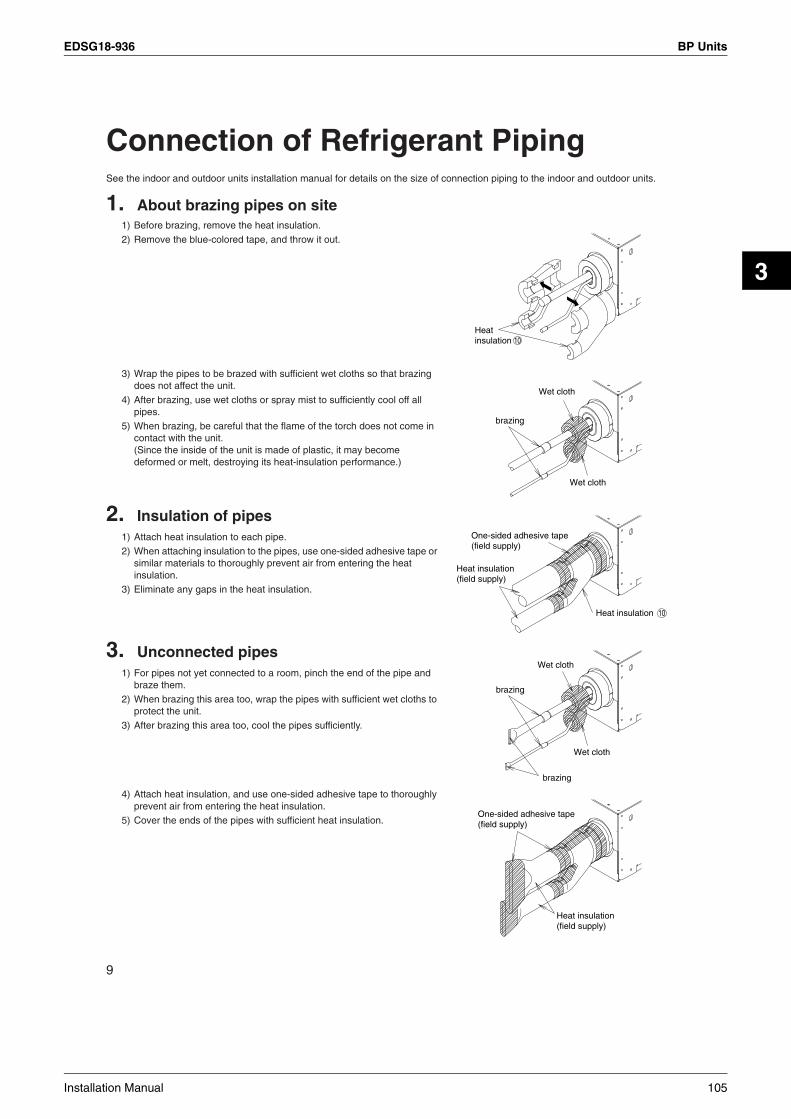
EDSG18-936 BP Units
3
9
Connection of Refrigerant PipingSee the indoor and outdoor units installation manual for details on the size of connection piping to the indoor and outdoor units.
1. About brazing pipes on site 1) Before brazing, remove the heat insulation.
2) Remove the blue-colored tape, and throw it out.
3) Wrap the pipes to be brazed with sufficient wet cloths so that brazing does not affect the unit.
4) After brazing, use wet cloths or spray mist to sufficiently cool off all pipes.
5) When brazing, be careful that the flame of the torch does not come in contact with the unit.(Since the inside of the unit is made of plastic, it may become deformed or melt, destroying its heat-insulation performance.)
2. Insulation of pipes 1) Attach heat insulation to each pipe.
2) When attaching insulation to the pipes, use one-sided adhesive tape or similar materials to thoroughly prevent air from entering the heat insulation.
3) Eliminate any gaps in the heat insulation.
3. Unconnected pipes 1) For pipes not yet connected to a room, pinch the end of the pipe and
braze them.
2) When brazing this area too, wrap the pipes with sufficient wet cloths to protect the unit.
3) After brazing this area too, cool the pipes sufficiently.
4) Attach heat insulation, and use one-sided adhesive tape to thoroughly prevent air from entering the heat insulation.
5) Cover the ends of the pipes with sufficient heat insulation.
Heat insulation 10
Wet cloth
Wet cloth
brazing
One-sided adhesive tape (field supply)
Heat insulation (field supply)
Heat insulation 10
Wet cloth
Wet cloth
brazing
brazing
Heat insulation (field supply)
One-sided adhesive tape (field supply)
Installation Manual 105

BP Units EDSG18-936
10
• After brazing and system leakage check, connect a heat insulation (field supply), and let it cure completely following the procedure illustrated right. Use the heat insulation with the following specifications: Thermal conductivity: 0.041-0.052W/mK (0.035-0.045kcal/mh˚C) / thickness 13mm or more Heat resistance = 100˚C or higher
• To ensure that the weight of the local interunit piping does not bear on directly on the BP unit, secure it near the BP unit using the clasp (field supply).
• When connecting indoor units, make sure to connect refrigerant pipes and connection wires to the appropriate connection ports marked with matching alphabets (A, B and C).
• When changing the routing direction, use the pipe joints and (accessories). Use pipe joints , and to connect refrigerant pipes with different diameters.
BP unit
Heat insulation 10
Heat insulation (field supply)
Heat insulation (field supply)
Indoor unit side piping Outdoor unit side piping
Place the heat insulation up against the BP unit to prevent any gaps from forming between the two, and wrap with masking tape as shown in the figure.
Clasp(field supply)
Clasp(field supply)
Room B(Gas)
Room C(Gas)
Room C(Liquid)
Room A(Gas)
Room A(Liquid)
Room B(Liquid)
⟨View from the indoor unit⟩
Hanger metal 7
2 6
3 4 5
NOTEWhen changing the direction of the piping to something other than the above, bend the piping on site.
I.D φ6.4Brazing
Piping (field supply)
Pipe joint 4
Outdoor unit side (Liquid)
Connecting φ6.4
interunit piping
Indoor unit side (Gas)
Brazing
Brazing
Brazing
When the direction is changed.I.D φ12.7I.D φ9.5When straight.
Pipe joint 2
Cut line for I.D φ15.9110
Cut line for O.D φ6.4
I.D φ9.5
Brazing
Pipe joint 5
Indoor unit side (Liquid)
Connecting φ9.5
interunit piping
Piping (field supply)
I.D φ15.9Brazing
Piping (field supply)
Pipe joint 3
I.D φ12.7Brazing
Piping (field supply)
Connection for φ15.9 piping. Connection for φ12.7 piping.
When straight.
Connection for φ19.1 and φ15.9 piping. Connection for φ12.7 piping.
Pipe joint 2 Cut line for I.D φ15.9
45
Pipe joint 3I.D φ12.7
Piping (field supply)
Brazing
When the direction is changed.
Outdoor unit side (Gas)
125
Pipe joint 6
Cut line for I.D φ12.7
I.D φ9.5
Piping (field supply)
Piping (field supply)
(125
)30
(70)
85 Pipe joint 6
Cut line for I.D φ12.7
Cut line for straight
I.D φ19.1
Brazing
Piping (field supply)
Cut line for I.D φ15.9
45(6
5)
106 Installation Manual
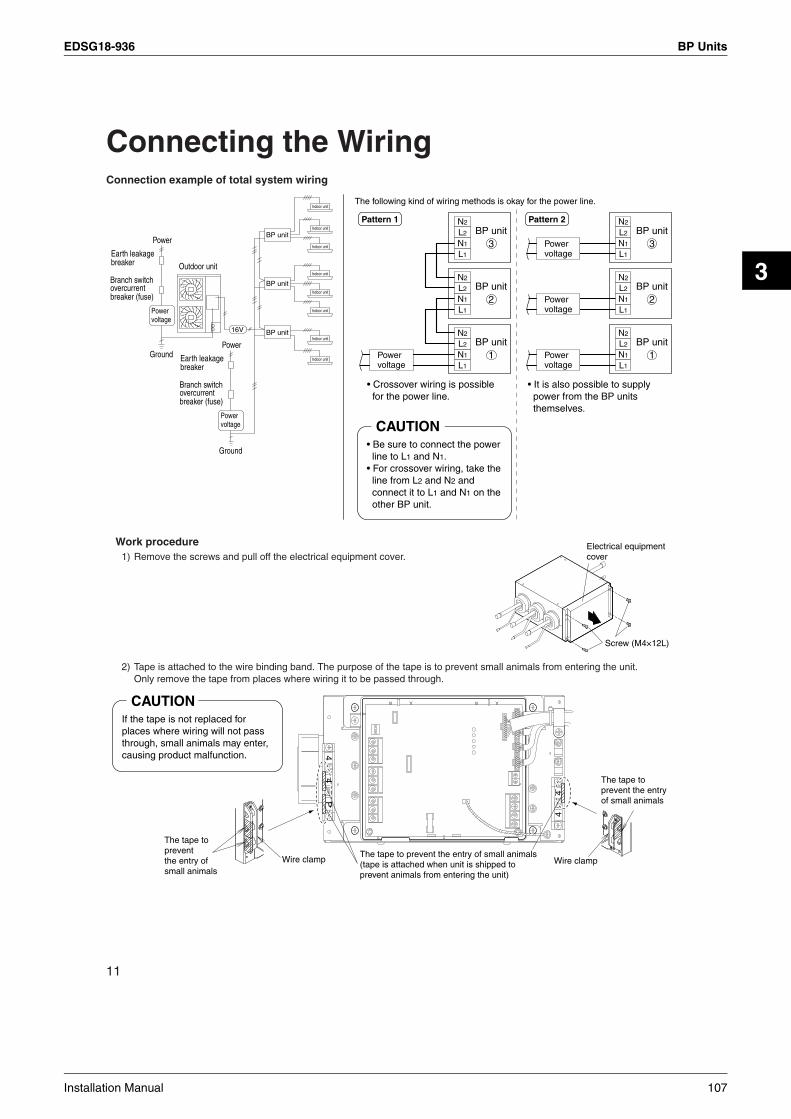
EDSG18-936 BP Units
3
11
Connecting the WiringConnection example of total system wiring
Work procedure 1) Remove the screws and pull off the electrical equipment cover.
2) Tape is attached to the wire binding band. The purpose of the tape is to prevent small animals from entering the unit. Only remove the tape from places where wiring it to be passed through.
Power
Ground
Outdoor unit
Power voltage
16V
Earth leakage breaker
overcurrent breaker (fuse)
Branch switch
Power
Ground
Power voltage
Earth leakage breaker
overcurrent breaker (fuse)
Branch switch
BP unit
Indoor unit
Indoor unit
Indoor unit
Indoor unit
Indoor unit
Indoor unit
Indoor unit
Indoor unit
BP unit
BP unit
Pattern 1BP unit
3
N2
L2
N1
L1
BP unit2
N2
L2
N1
L1
BP unit1
N2
L2
N1
L1
Powervoltage
Pattern 2BP unit
3
N2
L2
N1
L1
BP unit2
N2
L2
N1
L1
BP unit1
N2
L2
N1
L1
Powervoltage
Powervoltage
Powervoltage
• Be sure to connect the power line to L1 and N1.
• For crossover wiring, take the line from L2 and N2 and connect it to L1 and N1 on the other BP unit.
CAUTION
• Crossover wiring is possible for the power line.
• It is also possible to supply power from the BP units themselves.
The following kind of wiring methods is okay for the power line.
Electrical equipment cover
Screw (M4×12L)
CAUTIONIf the tape is not replaced for places where wiring will not pass through, small animals may enter, causing product malfunction.
The tape to prevent the entry of small animals (tape is attached when unit is shipped to prevent animals from entering the unit)
44
P
44
Wire clamp
The tape to prevent the entry of small animals
Wire clamp
The tape to prevent the entry of small animals
Installation Manual 107

BP Units EDSG18-936
12
3) Follow the instructions on the wiring nameplate to connect the connection wires of indoor/outdoor units to terminal block numbers. (1, 2, 3, F1 and F2) Always fix each ground wire separately with a ground screw. (See the figure below.)
(*) Only in protected pipes, use H07RN-F when protected pipes are not use. Specifications for local wiring power cord and branch wiring are in compliance with IEC60245.
4) Allow 300mm for the pulling-out section of harness.
5) Return the electrical equipment cover to its original position, and fix it with the screws.
F1F2
L2
N1
L1
N2
44
P
44
Wire clamp
10mm
NOTE: The terminal block numbers are arranged from top to bottom in order of 1, 2 and 3.
When wire length exceed10m, use 2.0mm wires.
Peel the outer coating leaving 10mm from the wire clamp.
Connection wire for indoor units. H05VV(*), 4 wires 1.6mm or 2.0mm
Power supply wire for indoor units. H05VV(*), 3 wires 1.6mm or 2.0mm
H05VV(*), 2 wires 0.75mm2 to 1.25mm2Wire clamp
For other BP unit (To L1, N1)
21
3
21
3
21
3Room A
Room B
Room C
Ground*Fix each wire separately.
Safety breaker 16A or 15A
Earth leakage circuit breaker
Power supply ~50Hz230V
Do not use tapped wires,stand wires, extensioncords, or starbust connections, as they may cause overtheating, electrical shock, or fire.
Warning
CAUTIONMistakenly connecting the power supply to this terminal block could cause control operating malfunctions.
Example ⟨For 3 rooms⟩
Binding band 9Secure the wires with binding band 9 to prevent them from coming out if pulled on from the outside.
Transmission wire (To other BP unit: F1, F2)
Transmission wire (To other BP unit: F1, F2 or to outdoor unit: F1, F2)
CAUTION• All local interunit wiring must be secured using the wire
binding band over the insulation, as shown in the figure.
• When connecting the connection wires to the terminal block using a single core wire, be sure to perform curling. Problems with the work may cause heat and fires.
Insulation
Wire binding band
+300mm of slack
+300mm of slack
Screw (M4×12L)
Install the electrical equipment cover.
108 Installation Manual

EDSG18-936 BP Units
3
13
Operating TestFollow the “Operating test” as described in the installation manual of the outdoor unit. If the BP unit does not operate normally during the test run, the error can be checked on the remote controller display for the indoor unit.
Error codes displayed on the remote controller
The BP UnitSimple diagnosis can be done using the LEDs on the BP unit’s circuit board. For details, see the label on the inside of the BP unit’s electrical equipment cover.
Malfunction code Nonconformity during installation Remedial action
A9Electric expansion valve connector not connected (BP unit)
Please contact your dealer.E2Printed circuit board faulty (BP unit)
J0Liquid and gas thermistor faulty (BP unit)
U4Transmission error between BP unit and indoor unit
Connect correctly the interconnections between BP unit and indoor unit.
U9Transmission error between outdoor unit and other BP unit
Connect correctly the interconnections between outdoor and other BP unit.
UJTransmission error between outdoor unit and this BP unit connecting with the indoor unit of error code displayed
Connect correctly the interconnections between outdoor and this BP unit connecting with the indoor unit of error code displayed.
3P155380-1E
Installation Manual 109

Indoor Units EDSG18-936
3. Indoor Units3.1 Safety Precautions
Safety Precautions• Read these Safety Precautions carefully to ensure correct installation.• This manual classifies the precautions into WARNING and CAUTION. Be sure to follow all the precautions below: they are all important for ensuring safety.
WARNING
CAUTION
WARNING
CAUTION
Failure to follow any of WARNING is likely to result in such grave consequences as death or serious injury.
Failure to follow any of CAUTION may result in grave consequences in some cases.
• The following safety symbols are used throughout this manual:
Be sure to observe this instruction. Be sure to establish an earth connection. Never attempt.
• After completing installation, test the unit to check for installation errors. Give the user adequate instructions concerning the use and cleaning of the unit according to the Operation Manual.
• Installation should be left to the dealer or another professional. Improper installation may cause water leakage, electrical shock, or fire.
• Install the air conditioner according to the instructions given in this manual. Incomplete installation may cause water leakage, electrical shock, or fire.
• Be sure to use the supplied or specified installation parts. Use of other parts may cause the unit to come to lose, water leakage, electrical shock, or fire.
• Install the air conditioner on a solid base that can support the weight of the unit. An inadequate base or incomplete installation may cause injury in the event the unit falls off the base.
• Electrical work should be carried out in accordance with the installation manual and the national electrical wiring rules or code of practice. Insufficient capacity or incomplete electrical work may cause electrical shock or fire.
• Be sure to use a dedicated power circuit. Never use a power supply shared by another appliance.
• The installation height from the floor must be over 1.8m.
• Use the specified types of wires for electrical connections between the indoor and outdoor units. When installing wiring for the outdoor unit, after cutting the wires for each connection point, a length of 3mm or longer is required. Firmly clamp the interconnecting wires so their terminals receive no external stresses. Incomplete connections or clamping may cause terminal overheating or fire.
• For wiring, use a cable length enough to cover the entire distance with no connection. Do not use an extension cord. Do not put other loads on the power supply, use a dedicated power circuit. (Failure to do so may cause abnormal heat, electric shock or fire.) The power supply wire class for the receptacle for the outdoor unit must be polychlorinated vinyl insulation or higher. (IEC60057: No. 245 wire)
• After all installation is complete, check to make sure that no refrigerant is leaking out. (The refrigerant produces a toxic gas if exposed to flames.)
• Do not install the air conditioner in a place where there is danger of exposure to inflammable gas leakage. If the gas leaks and builds up around the unit, it may catch fire.
• Establish drain piping according to the instructions of this manual. Inadequate piping may cause flooding.
• Tighten the flare nut according to the specified method such as with a torque wrench. If the flare nut is tightened too hard, the flare nut may crack after a long time and cause refrigerant leakage.
• Note for installing the outdoor unit. (For heat pump model only.) In cold area where the outside air temperature keep below or around freezing-point for a few days, the outdoor unit’s drain may freeze. If so, it is recommended to install an electric heater in order to protect drain from freezing. It is recommended that you contact the after-sales service organization.
• After connecting interconnecting and supply wiring be sure to shape the cables so that they do not put undue force on the electrical covers or panels. Install covers over the wires. Incomplete cover installation may cause terminal overheating, electrical shock, or fire. When electrical appliances are connected in Y formation, if the power supply is damaged in some way, to avoid danger the power supply must be replaced by the maker or by someone with an equivalent certification.
• When installing or relocating the system, be sure to keep the refrigerant circuit free from substances other than the specified refrigerant (R410A), such as air. (Any presence of air or other foreign substance in the refrigerant circuit causes an abnormal pressure rise or rupture, resulting in injury.)
• If any refrigerant has leaked out during the installation work, ventilate the room. (The refrigerant produces a toxic gas if exposed to flames.)
• Be sure to establish an earth. Do not earth the unit to a utility pipe, arrester, or telephone earth. Incomplete earth may cause electrical shock, or fire. A high surge current from lightning or other sources may cause damage to the air conditioner.
• Be sure to install an earth leakage breaker. Failure to install an earth leakage breaker may result in electric shocks, or fire.
• During pump-down, stop the compressor before removing the refrigerant piping. If the compressor is still running and the shut-off valve is open during pump-down, air will be sucked in when the refrigerant piping is removed, causing abnormal pressure in the freezer cycle which will lead to breakage and even injury.
• During installation, attach the refrigerant piping securely before running the compressor. If the compressor is not attached and the shut-off valve is open during pump-down, air will be sucked in when the compressor is run, causing abnormal pressure in the freezer cycle which will lead to breakage and even injury.
110 Installation Manual

EDSG18-936 Indoor Units
3
3.2 Wall Mounted Type FTKS25/35D
Accessories
Choosing an Installation Site
Installation Tips
A Mounting plate
E Remote controller holder
F Fixing screws for remote controller holder M3 × 20L
H Indoor unit fixing screwsM4 × 12L
G AAA dry-cell batteries
J Insulation tape
K Operation manual
L Installation manual
1
6
2
1
1
2
2
2
1
1
1
D Wireless remote controller
C Titanium Apatite PhotocatalyticAir-Purifying Filter
B Mounting platefixing screwsM4 × 25L
1. Indoor unit.• The indoor unit should be sited in a place where:1) the restrictions on installation specified in the indoor unit installation drawings are met,2) both air intake and exhaust have clear paths met,3) the unit is not in the path of direct sunlight,4) the unit is away from the source of heat or steam,5) there is no source of machine oil vapour (this may shorten indoor unit life),6) cool (warm) air is circulated throughout the room,7) the unit is away from electronic ignition type fluorescent lamps (inverter or rapid start type) as they may shorten the
remote control range,8) the unit is at least 1 metre away from any television or radio set (unit may cause interference with the picture or sound).9) install at the recommended height (1.8m).
2. Wireless remote controller.1) Turn on all the fluorescent lamps in the room, if any, and find the site where remote control signals are properly
received by the indoor unit (within 7 metres).
1. Removing and installing front panel.• Removal method
Hook fingers on the panel protrusions on the left and right of the main body, and open until the panel stops. Slide the front panel sideways to disengagethe rotating shaft. Then pull the front panel toward you to remove it.
• Installation methodAlign the tabs of the front panel with the grooves, and push all the way in. Then close slowly. Push the center of the lower surface of the panel firmly to engage the tabs.
• Before choosing the installation site, obtain user approval.
2. Removing and installing front grille.• Removal method
1) Remove front panel to remove the air filter.2) Remove the front grille.3) In front of the mark of the front grille,
there are 3 upper hooks. Lightly pull the front grille toward you with one hand, and push down on the hooks with the fingers of your other hand.
mark area (3 locations)
Upper hook
Lightly pull the front grille toward you with one hand, and push down on the hooks with the fingers of your other hand. (3 locations)
Pushdown.
Upper hook
Upper hook
<When there is no work space because the unit is close to ceiling>
Be sure to wear protection gloves.
Caution1) Push up.
2) Pull toward you.Place both hands under the center of the front grille, and while pushing up, pull it toward you.
• Installation method1) Install the front grille and firmly engage the upper hooks (3 locations).2) Install 2screws of the front grille.3) Install the air filter and then mount the front panel.
3. How to set the different addresses.When two indoor units are installed in one room, the two wireless remote controllers can be set for different addresses.1) In the same way as when
connecting to an HA system, remove the metal plate electrical wiring cover.
2) Cut the address jumper (JA) on the pindted circuit board.
3) Cut the address jumper (J4) in the remote control.
ADDR
ESS
JA
ADDRESSJAEXIST 1CUT 2
Push the rotating shaft of the front panel into the groove.
ADDRESSJ4EXIST CUT
12
J4
Installation Manual 111
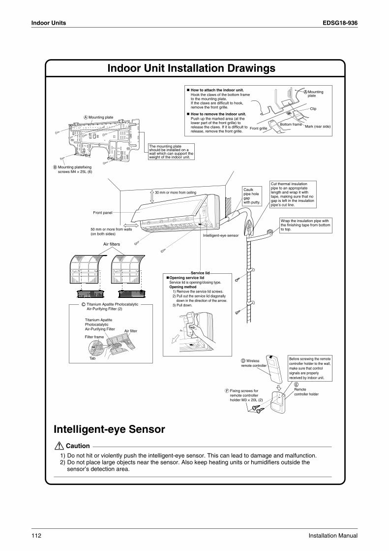
Indoor Units EDSG18-936
30 mm or more from ceiling
Front panel
50 mm or more from walls (on both sides) Intelligent-eye sensor
Indoor Unit Installation Drawings
Wrap the insulation pipe with the finishing tape from bottom to top.
Cut thermal insulation pipe to an appropriate length and wrap it with tape, making sure that no gap is left in the insulation pipe’s cut line.
Caulk pipe hole gap with putty.
C Titanium Apatite Photocatalytic Air-Purifying Filter (2)
Intelligent-eye Sensor
1) Do not hit or violently push the intelligent-eye sensor. This can lead to damage and malfunction.2) Do not place large objects near the sensor. Also keep heating units or humidifiers outside the
sensor’s detection area.
Caution
D Wireless remote controller
E Remote controller holder
Before screwing the remote controller holder to the wall, make sure that control signals are properly received by indoor unit.
The mounting plate should be installed on a wall which can support the weight of the indoor unit.
A Mounting plate
A Mountingplate
Clip
Mark (rear side)Bottom frameFront grille
How to attach the indoor unit.Hook the claws of the bottom frameto the mounting plate.If the claws are difficult to hook,remove the front grille.
How to remove the indoor unit.Push up the marked area (at thelower part of the front grille) torelease the claws. If it is difficult torelease, remove the front grille.
Air filter
Titanium Apatite Photocatalytic Air-Purifying Filter
Filter frame
Tab
Mounting platefixing screws M4 × 25L (6)
B
Fixing screws for remote controller holder M3 × 20L (2)
F
Service lidOpening service lidService lid is opening/closing type.Opening method
1) Remove the service lid screws.2) Pull out the service lid diagonally
down in the direction of the arrow.3) Pull down.
Air filters
112 Installation Manual

EDSG18-936 Indoor Units
3
Indoor Unit Installation1. Installing the mounting plate.
• The mounting plate should be installed on a wall which can support the weight of the indoor unit.1) Temporarily secure the mounting plate to the wall, make sure that the panel is completely level, and mark
the boring points on the wall.2) Secure the mounting plate to the wall with screws.
Recommended mounting-plate retention spots and dimensions
2. Boring a wall hole and installing wall embedded pipe.• For walls containing metal frame or metal board, be sure to use a wall
embedded pipe and wall cover in the feed-through hole to prevent possible heat, electrical shock, or fire.
• Be sure to caulk the gaps around the pipes with caulking material to prevent water leakage.
1) Bore a feed-through hole of 65 mm in the wall so it has a down slope toward the outside.
2) Insert a wall pipe into the hole.3) Insert a wall cover into wall pipe.4) After completing refrigerant piping, wiring, and drain piping, caulk pipe
hole gap with putty.
Inside Outside
Caulking
Wall embedded pipe (field supply)
Wall hole cover(field supply)
Wall embedded pipe (field supply)
φ65
80
100
400
135
450
283
47.5
141.
5
50.5
46.5
44.513
1.5 87
44.5
110
60 130
220 50
60 110
800
φ65 φ65
Use tape measure as shown.Position the end of a tape measure at ∇.
Keep here the piece cut out from the unit for pipingGas pipe end
Liquid pipe end
* The removed pipe port cover can be kept in the mounting plate pocket. Removed pipe
port cover
A Mounting plate
Through-the-wall hole φ65mm
Drain hose position
Recommended mounting - plate retention spots (6 spots in all)
(Bolt size : M10)
Place a leveler on raised tab.
b
(Bolt size : M10)
Installation Manual 113
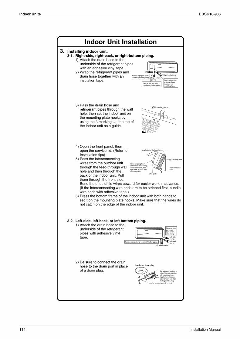
Indoor Units EDSG18-936
Indoor Unit Installation3. Installing indoor unit.
3-1. Right-side, right-back, or right-bottom piping.1) Attach the drain hose to the
underside of the refrigerant pipes with an adhesive vinyl tape.
2) Wrap the refrigerant pipes and drain hose together with an insulation tape.
3) Pass the drain hose and refrigerant pipes through the wall hole, then set the indoor unit on the mounting plate hooks by using the markings at the top of the indoor unit as a guide.
4) Open the front panel, then open the service lid. (Refer to Installation tips)
5) Pass the interconnecting wires from the outdoor unit through the feed-through wall hole and then through the back of the indoor unit. Pull them through the front side. Bend the ends of tie wires upward for easier work in advance. (If the interconnecting wire ends are to be stripped first, bundle wire ends with adhesive tape.)
6) Press the bottom frame of the indoor unit with both hands to set it on the mounting plate hooks. Make sure that the wires do not catch on the edge of the indoor unit.
3-2. Left-side, left-back, or left bottom piping.1) Attach the drain hose to the
underside of the refrigerant pipes with adhesive vinyl tape.
2) Be sure to connect the drain hose to the drain port in place of a drain plug.
Right-bottom piping
Right-back piping
Bind coolant pipe and drain hose together with insulating tape.
Remove pipe port cover here for right-side piping.
Remove pipe port cover here for right-bottom piping.
Mounting plateA
Wire guide
When stripping the ends of interconnecting wires in advance, bind right ends of wires with insulating tape.
Hang indoor unit’s hook here.
Interconnectingwires
Mounting plateA
Remove pipe port cover here for left-bottom piping.
Remove pipe port cover here for left-side piping.
Left-bottom piping
Left-side pipingLeft-back piping
How to set drain plug
No gapDo not apply lubricating oil (refrigerant machine oil) when inserting.Application of causes deterioration and drain leakage of the plug.
Insert a hexagon wrench (4 mm)
114 Installation Manual

EDSG18-936 Indoor Units
3
Indoor Unit Installation3) Shape the refrigerant pipe along the pipe path marking on the
mounting plate.4) Pass drain hose and refrigerant pipes through the wall hole,
then set the indoor unit on mounting plate hooks, using the markings at the top of indoor unit as a guide.
5) Pull in the interconnecting wires.6) Connect the inter-unit piping.7) Wrap the refrigerant pipes and drain hose together with insulation
tape as right figure, in case of setting the drain hose through the back of the indoor unit.
8) While exercising care so that the interconnecting wires do not catch indoor unit, press the bottom edge of indoor unit with both hands until it is firmly caught by the mounting plate hooks. Secure indoor unit to the mounting plate with the screws (M4 × 12L).
3-3. Wall embedded piping.Follow the instructions given under
1) Insert the drain hose to this depth so it won’t be pulled out of the drain pipe.
4. Wiring. , install as described in the installation
manual supplied with the Multi outdoor unit.1) Strip wire ends (15 mm).2) Match wire colours with
terminal numbers on indoor and outdoor unit’s terminal blocks and firmly screw wires to the corresponding terminals.
3) Connect the earth wires to the corresponding terminals.
4) Pull wires to make sure that they are securely latched up, then retain wires with wire retainer.5) In case of connecting to an adapter system. Run the remote control
cable and attach the S21. (Refer to 5. When connecting to an HA system.)
6) Shape the wires so that the service lid fits securely, then close service lid.
Wrap insulating tape around the bent portion of refrigerant pipe. Overlap at least half the width of the tape with each turn.
Drain hose
Caulk this hole with putty or caulking material. Bind with plastic
tape.
A Mounting plate
Refrigerantpipes
Drain hose
Bottom frame
H M4 × 12L (2 point)
Mountingplate
A
Left-side, left-back, or left bottom pipingInner wall
Vinyl chloride drain pipe (VP-30)
Drain hose50 mm or more
Insert drain hose to this depth so it won’t be pulled out of drain pipe.
Outer wall
With a Multi indoor unit
123
1 2 3 L N
Safety breaker 15A
Earth leakage circuit breaker
Earth
When wire length exceeds 10 m, use 2.0-mm wires.
H05VV
Firmly fix the wires with the terminal screws.
Outdoor unit
Indoor unit
Powersupply50Hz 220V - 240V60Hz 220V - 230VFirmly fix the wires with
the terminal screws.
1) Do not use tapped wires, stand wires, extensioncords, or starbust connections, as they may cause overtheating, electrical shock,or fire.
2) Do not use locally purchased electrical parts inside the product. (Do not branch the power for the drain pump, etc., from the terminal block.) Doing so may cause electric shock or fire.
Warning
Shape wires so that the service lid will fit securely.
Terminal block
Electrical component box
Wire retainer
Firmly secure wire retainer so that wires sustain no external stress.Use the
specified wire type.
Installation Manual 115

Indoor Units EDSG18-936
Indoor Unit Installation5. When connecting to an HA system.
1) Remove the front grille. (2 screws)2) Remove the electrical wiring box. (1 screw)3) Remove the metal plate electrical wiring cover. (3 tabs)4) Attach the connection cord to the S21 connector and pull the
harness out through the notched part in the figure.5) Replace the electrical wiring cover as it was, and pull the harness
around, as shown in the figure.
6. Drain piping.1) Connect the drain hose, as described
right.
2) Remove the air filters and pour some water into the drain pan to check the water flows smoothly.
3) When drain hose requires extension, obtain an extension hose commercially available.Be sure to thermally insulate the indoor section of the extension hose.
4) When connecting a rigid polyvinyl chloride pipe (nominal diameter 13 mm) directly to the drain hose attached to the indoor unit as with embedded piping work, use any commercially available drain socket (nominal diameter 13 mm) as a joint.
The drain hose should be inclined downward.
No trap is permitted.
Do not put the end of the hose in water.
Indoor unit drain hose φ
18 Extension drain hose
Heat insulation tube(Field supply)
Drain hose supplied with the indoor unit
Commercially available drain socket (nominal diameter 13 mm)
Commercially available rigid polyvinyl chloride pipe(nominal diameter 13 mm)
φ 18
Screw
HA connector(S21)
4) 5) Replace the electrical wiring cover as it was, and pull the harness around, as shown in the figure.
Attach the connection cord to the S21 connector and pull the harness out through the notched part in the figure.
3) Remove the metal plate electrical wiring cover.
TabPush
Slide
PullTab
Slide
HA cord
Notched part
116 Installation Manual

EDSG18-936 Indoor Units
3
, install as described in the installation manual supplied with the Multi outdoor unit.With a Multi indoor unit
2. Refrigerant piping.
2-1. Caution on piping handling.1) Protect the open end of the pipe against dust and moisture.2) All pipe bends should be as gentle as possible. Use a pipe
bender for bending.
2-2. Selection of copper and heat insulation materials.• When using commercial copper pipes and fittings, observe the following:1) Insulation material: Polyethylene foam
Heat transfer rate: 0.041 to 0.052 W/mK (0.035 to 0.045 kcal/(mh •˚C))Refrigerant gas pipe’s surface temperature reaches 110˚C max.Choose heat insulation materials that will withstand this temperature.
2) Be sure to insulate both the gas and liquid piping and to provide insulation dimensions as below.
3) Use separate thermal insulation pipes for gas and liquid refrigerant pipes.
Wall
If no flare cap is available, cover the flare mouth with tape to keep dirt or water out.
Be sure to place a cap.
Rain
Gas pipeLiquid pipe
Gas pipe insulation
Liquid pipe insulation
Finishing tape Drain hose
Inter-unit wiring
Refrigerant Piping Work
1. Flaring the pipe end.1) Cut the pipe end with a pipe cutter.2) Remove burrs with the cut surface facing downward
so that the chips do not enter the pipe.3) Put the flare nut on the pipe.4) Flare the pipe.5) Check that the flaring is properly made.
1) Do not use mineral oil on flared part.2) Prevent mineral oil from getting into the system as this would reduce the lifetime of the units.3) Never use piping which has been used for previous installations. Only use parts which are delivered with the unit.4) Do never install a drier to this R410A unit in order to guarantee it’s lifetime.5) The drying material may dissolve and damage the system.6) Incomplete flaring may cause refrigerant gas leakage.
Warning
(Cut exactly at right angles.) Remove burrs
Set exactly at the position shown below.
A
Flaring
Die A 0 ~ 0.5 mm
Clutch-type
Flare tool for R410A
1.0 ~ 1.5 mm
Clutch-type (Rigid-type)
1.5 ~ 2.0 mm
Wing-nut type (Imperial-type)
Conventional flare tool
CheckFlare’s inner surface must be flaw-free.
The pipe end must be evenly flared in a perfect circle.
Make sure that the flare nut is fitted.
Flare nut tightening torque Gas side Liquid side 3/8 inch 1/4 inch 32.7-39.9N • m 14.2-17.2N • m (333-407kgf • cm) (144-175kgf • cm)
Gas side Gas pipe thermal insulation
20/25/35 class
O.D. 6.4mmO.D. 9.5mm
Minimum bend radius
30mm or more
Thickness 0.8mm (C1220T-O)
20/25/35 class
I.D. 12-15mm I.D. 8-10mm
Thickness 10mm Min.
Liquid sideLiquid pipe
thermal insulation
1) Use the flare nut fixed to the main unit. (To prevent cracking of the flare nut by aged deterioration.)2) To prevent gas leakage, apply refrigeration oil only to the inner surface of the flare. (Use refrigeration oil for R410A.)3) Use torque wrenches when tightening the flare nuts to prevent damage to the flare nuts and gas leakage.
Align the centres of both flares and tighten the flare nuts 3 or 4 turns by hand. Then tighten them fully with the torque wrenches.
CAUTION
Do not apply refrigeration
oil to the outer surface.
Flare nut
Apply refrigeration oil to the
inner surface of the flare.
Do not apply refrigeration oil to the flare
nut avoid tightening with over torque.
[Apply oil]
Torque wrench
Piping union
Flare nut
Spanner
[Tighten]
Installation Manual 117
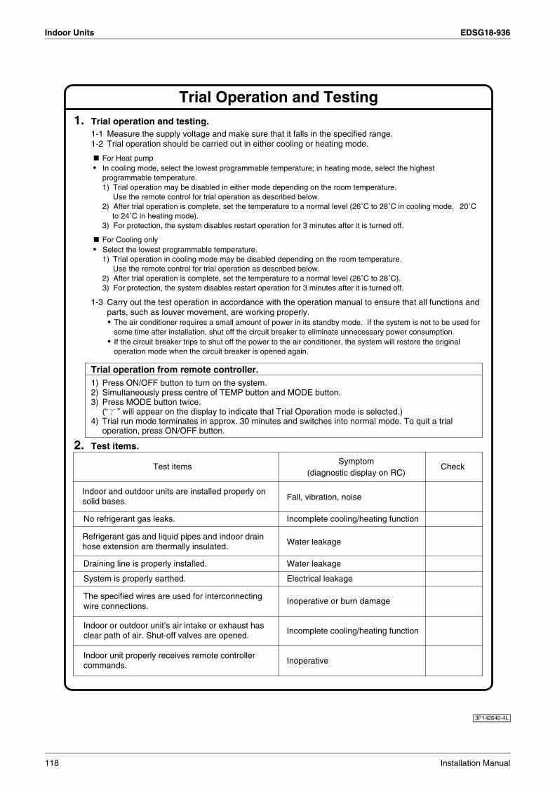
Indoor Units EDSG18-936
1. Trial operation and testing.1-1 Measure the supply voltage and make sure that it falls in the specified range.1-2 Trial operation should be carried out in either cooling or heating mode.
For Heat pump•
•
In cooling mode, select the lowest programmable temperature; in heating mode, select the highest programmable temperature.1) Trial operation may be disabled in either mode depending on the room temperature.
Use the remote control for trial operation as described below.2) After trial operation is complete, set the temperature to a normal level (26˚C to 28˚C in cooling mode, 20˚C
to 24˚C in heating mode).3) For protection, the system disables restart operation for 3 minutes after it is turned off.
For Cooling onlySelect the lowest programmable temperature.1) Trial operation in cooling mode may be disabled depending on the room temperature.
Use the remote control for trial operation as described below.2) After trial operation is complete, set the temperature to a normal level (26˚C to 28˚C).3) For protection, the system disables restart operation for 3 minutes after it is turned off.
1-3 Carry out the test operation in accordance with the operation manual to ensure that all functions and parts, such as louver movement, are working properly.• The air conditioner requires a small amount of power in its standby mode. If the system is not to be used for
some time after installation, shut off the circuit breaker to eliminate unnecessary power consumption.• If the circuit breaker trips to shut off the power to the air conditioner, the system will restore the original
operation mode when the circuit breaker is opened again.
Trial operation from remote controller.1) Press ON/OFF button to turn on the system.2) Simultaneously press centre of TEMP button and MODE button.3) Press MODE button twice.
(“ ” will appear on the display to indicate that Trial Operation mode is selected.)4) Trial run mode terminates in approx. 30 minutes and switches into normal mode. To quit a trial
operation, press ON/OFF button.
2. Test items.
Test items
Incomplete cooling/heating functionNo refrigerant gas leaks.
Draining line is properly installed.
Indoor and outdoor units are installed properly on solid bases.
Refrigerant gas and liquid pipes and indoor drain hose extension are thermally insulated.
Fall, vibration, noise
Water leakage
Water leakage
System is properly earthed. Electrical leakage
Indoor unit properly receives remote controller commands. Inoperative
Indoor or outdoor unit’s air intake or exhaust has clear path of air. Shut-off valves are opened. Incomplete cooling/heating function
The specified wires are used for interconnecting wire connections.
Inoperative or burn damage
Symptom(diagnostic display on RC)
Check
Trial Operation and Testing
3P142640-4L
118 Installation Manual
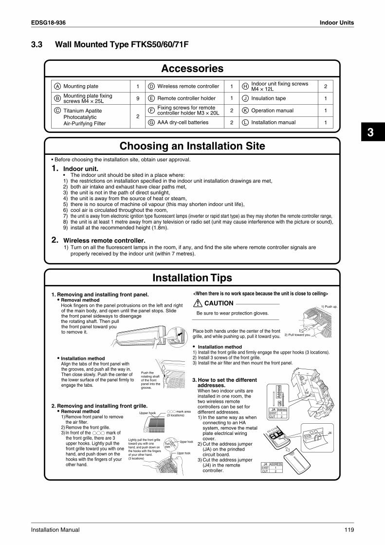
EDSG18-936 Indoor Units
3
3.3 Wall Mounted Type FTKS50/60/71F
1. Indoor unit.• The indoor unit should be sited in a place where:1) the restrictions on installation specified in the indoor unit installation drawings are met,2) both air intake and exhaust have clear paths met,3) the unit is not in the path of direct sunlight,4) the unit is away from the source of heat or steam,5) there is no source of machine oil vapour (this may shorten indoor unit life),6) cool air is circulated throughout the room,7) the unit is away from electronic ignition type fluorescent lamps (inverter or rapid start type) as they may shorten the remote controller range,8) the unit is at least 1 metre away from any television or radio set (unit may cause interference with the picture or sound),9) install at the recommended height (1.8m).
2. Wireless remote controller.1) Turn on all the fluorescent lamps in the room, if any, and find the site where remote controller signals are
properly received by the indoor unit (within 7 metres).
• Before choosing the installation site, obtain user approval.
A
B
C
D
E
F
G
H
J
K
L
1 1
1 19
12
2
12
Mounting plate
Titanium Apatite PhotocatalyticAir-Purifying Filter
Wireless remote controller
Remote controller holder
AAA dry-cell batteries
Fixing screws for remote controller holder M3 × 20L Operation manual
Installation manual
Mounting plate fixing screws M4 × 25L Insulation tape
2Indoor unit fixing screwsM4 × 12L
Accessories
Choosing an Installation Site
Installation Tips1. Removing and installing front panel.
• Removal methodHook fingers on the panel protrusions on the left and right of the main body, and open until the panel stops. Slide the front panel sideways to disengagethe rotating shaft. Then pull the front panel toward you to remove it.
• Installation methodAlign the tabs of the front panel with the grooves, and push all the way in. Then close slowly. Push the center of the lower surface of the panel firmly to engage the tabs.
2. Removing and installing front grille.• Removal method
1)Remove front panel to remove the air filter.
2) Remove the front grille.3) In front of the mark of
the front grille, there are 3 upper hooks. Lightly pull the front grille toward you with one hand, and push down on the hooks with the fingers of your other hand.
<When there is no work space because the unit is close to ceiling>
Be sure to wear protection gloves.
CAUTION
Place both hands under the center of the front grille, and while pushing up, pull it toward you.
• Installation method1) Install the front grille and firmly engage the upper hooks (3 locations).2) Install 3 screws of the front grille.3) Install the air filter and then mount the front panel.
3. How to set the different addresses.When two indoor units are installed in one room, the two wireless remote controllers can be set for different addresses.1) In the same way as when
connecting to an HA system, remove the metal plate electrical wiring cover.
2) Cut the address jumper (JA) on the prindted circuit board.
3) Cut the address jumper (J4) in the remote controller.
mark area (3 locations)
Upper hook
Lightly pull the front grille toward you with one hand, and push down on the hooks with the fingers of your other hand.(3 locations)
Pushdown.
Upper hook
Upper hook
Addr
ess
JA
AddressJAEXIST 1CUT 2
Push the rotating shaft of the front panel into the groove.
ADDRESSJ4EXIST CUT
12
J4
1) Push up.
2) Pull toward you.
Installation Manual 119

Indoor Units EDSG18-936
Indoor Unit Installation Drawings
Intelligent-eye Sensor
1) Do not hit or violently push the intelligent-eye sensor. This can lead to damage and malfunction.2) Do not place large objects near the sensor. Also keep heating units or humidifiers outside the
sensor’s detection area.
CAUTION
30mm or more from ceiling
Front panel
50mm or more from walls (on both sides)
Intelligent-eye sensor
Wrap the insulation pipe with the finishing tape from bottom to top.
Cut thermal insulation pipe to an appropriate length and wrap it with tape, making sure that no gap is left in the insulation pipe’s cut line.
Caulk pipe hole gap with putty.
C Titanium Apatite Photocatalytic Air-Purifying Filter (2)
D Wireless remote controller
E Remote controller holder
Before screwing the remote controller holder to the wall, make sure that control signals are properly received by indoor unit.
How to attach the indoor unit.Hook the claws of the bottom frameto the mounting plate.If the claws are difficult to hook,remove the front grille.
How to remove the indoor unit.Push up the marked area (at thelower part of the front grille) torelease the claws. If it is difficult torelease, remove the front grille.
Mounting plate fixing screws M4 × 25L (9)
B
Fixing screws for remote controller holder M3 × 20L (2)
F
Service lidOpening service lidService lid is opening/closing type.Opening method
1) Remove the service lid screws.2) Pull out the service lid diagonally
down in the direction of the arrow.3) Pull down.
Air filters
Tabs (upper 3 locations)
Tabs (lower 3 locations)
Insert the upper side of the Titanium Apatite Photocatalytic Air-purifying filter into the tabs (upper 3 locations),push the lower side of the filters up a little and into the tabs (lower 3 locations).
C
A Mounting plate
The mounting plate should be installed on a wall which can support the weight of the indoor unit.
Front grille
A Mountingplate
Clip
Bottom frame
Mark (rear side)
M4 × 16L
M4 × 16L
120 Installation Manual

EDSG18-936 Indoor Units
3
1. Installing the mounting plate.• The mounting plate should be installed on a wall which can support the weight of the indoor unit.1) Temporarily secure the mounting plate to the wall, make sure that the panel is completely level, and
mark the boring points on the wall.2) Secure the mounting plate to the wall with screws.
Recommended mounting plate retention spots and dimensions
2. Boring a wall hole and installing wall embedded pipe.• For walls containing metal frame or metal board, be sure to use a wall
embedded pipe and wall cover in the feed-through hole to prevent possible heat, electrical shock, or fire.
• Be sure to caulk the gaps around the pipes with caulking material to prevent water leakage.
1) Bore a feed-through hole of 80mm in the wall so it has a down slope toward the outside.
2) Insert a wall pipe into the hole.3) Insert a wall cover into wall pipe.4) After completing refrigerant piping, wiring, and drain piping, caulk pipe
hole gap with putty.
Indoor Unit Installation (1)
125
60 83 413.5 44.5
290
52
105099.5
5290
55
100
100
Through-the-wall hole φ80mmDrain hose position
φ80 φ80
Recommended mounting plate retention spots (9 spots in all)
(Bolt size : M10) (Bolt size : M10)
Place a leveler on raised tab.
Use tape measure as shown.Position the end of a tape measure at ∇.
Gas pipe end Liquid pipe end
(length: mm)
Inside Outside
Caulking
Wall embedded pipe (Field supply)
Wall hole cover(Field supply)
Wall embedded pipe (Field supply)
φ80
* The removed pipe port cover can be kept in the mounting plate pocket. Removed pipe
port cover
A Mounting plate
Installation Manual 121
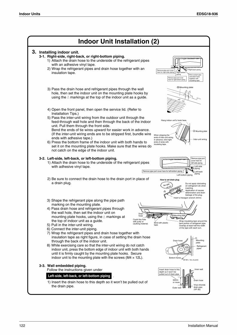
Indoor Units EDSG18-936
Indoor Unit Installation (2)
3. Installing indoor unit.3-1. Right-side, right-back, or right-bottom piping.
1) Attach the drain hose to the underside of the refrigerant pipes with an adhesive vinyl tape.
2) Wrap the refrigerant pipes and drain hose together with an insulation tape.
3) Pass the drain hose and refrigerant pipes through the wall hole, then set the indoor unit on the mounting plate hooks by using the markings at the top of the indoor unit as a guide.
4) Open the front panel, then open the service lid. (Refer to Installation Tips.)
5) Pass the inter-unit wiring from the outdoor unit through the feed-through wall hole and then through the back of the indoor unit. Pull them through the front side. Bend the ends of tie wires upward for easier work in advance. (If the inter-unit wiring ends are to be stripped first, bundle wire ends with adhesive tape.)
6) Press the bottom frame of the indoor unit with both hands to set it on the mounting plate hooks. Make sure that the wires do not catch on the edge of the indoor unit.
3-2. Left-side, left-back, or left-bottom piping.1) Attach the drain hose to the underside of the refrigerant pipes
with adhesive vinyl tape.
2) Be sure to connect the drain hose to the drain port in place of a drain plug.
3) Shape the refrigerant pipe along the pipe path marking on the mounting plate.
4) Pass drain hose and refrigerant pipes through the wall hole, then set the indoor unit on mounting plate hooks, using the markings at the top of indoor unit as a guide.
5) Pull in the inter-unit wiring.6) Connect the inter-unit piping.7) Wrap the refrigerant pipes and drain hose together with
insulation tape as right figure, in case of setting the drain hose through the back of the indoor unit.
8) While exercising care so that the inter-unit wiring do not catch indoor unit, press the bottom edge of indoor unit with both hands until it is firmly caught by the mounting plate hooks. Secure indoor unit to the mounting plate with the screws (M4 × 12L).
3-3. Wall embedded piping.Follow the instructions given under
1) Insert the drain hose to this depth so it won’t be pulled out of the drain pipe.
Right-bottom piping
Right-back piping
Bind coolant pipe and drain hose together with insulating tape.
Remove pipe port cover here for right-side piping.
Remove pipe port cover here for right-bottom piping.
Mounting plateA
When stripping the ends of inter-unit wiring in advance, bind right ends of wires with insulating tape.
Hang indoor unit’s hook here.
Inter-unit wiring
Mounting plateA
Remove pipe port cover here for left-bottom piping.
Remove pipe port cover here for left-side piping.
Left-bottom piping
Left-side piping
Left-back piping
How to set drain plug
No gap Do not apply lubricating oil (refrigerant oil) when inserting.Application of causes deterioration and drain leakage of the plug.
Insert a hexagon wrench (4mm)
Wrap insulating tape around the bent portion of refrigerant pipe. Overlap at least half the width of the tape with each turn.
Drain hose
Caulk this hole with putty or caulking material. Bind with plastic
tape.
A Mounting plate
Refrigerantpipes
Drain hose
Bottom frameH M4 × 12L (2 point)
Mountingplate
A
Left-side, left-back, or left-bottom piping .
Inner wall
Vinyl chloride drain pipe (VP-30)
Drain hose50mm or more
Insert drain hose to this depth so it won’t be pulled out of drain pipe.
Outer wall
122 Installation Manual

EDSG18-936 Indoor Units
3
5. When connecting to an HA system.1) Remove the front grille.
(3 screws)2) Remove the electrical
wiring box. (1 screw)3) Remove the metal plate
electrical wiring cover. (4 tabs)
4) Attach the connection cord to the S21 connector and pull the harness out through the notched part in the figure.
5) Replace the electrical wiring cover as it was, and pull the harness around, as shown in the figure.
Indoor Unit Installation (3)
4. Wiring. , install as described in the installation
manual supplied with the Multi outdoor unit.1) Strip wire ends (15mm).2) Match wire colours with terminal numbers on indoor and
outdoor unit’s terminal blocks and firmly screw wires to the corresponding terminals.
3) Connect the earth wires to the corresponding terminals.4) Pull wires to make sure that they are securely latched up,
then retain wires with wire retainer.5) In case of connecting to an adapter system. Run the remote
controller cable and attach the S21. (Refer to 5. When connecting to an HA system.)
6) Shape the wires so that the service lid fits securely, then close service lid.
1) Do not use tapped wires, stranded wires, extensioncords, or starburst connections, as they may cause overtheating, electrical shock,or fire.
2) Do not use locally purchased electrical parts inside the product. (Do not branch the power for the drain pump, etc., from the terminal block.) Doing so may cause electric shock or fire.
WARNING
6. Drain piping.1) Connect the drain hose, as described below.
2) Remove the air filters and pour some water into the drain pan to check the water flows smoothly.
3) When drain hose requires extension, obtain
an extension hose commercially available.Be sure to thermally insulate the indoor section of the extension hose.
4) When connecting a rigid polyvinyl chloride pipe (nominal diameter 13mm) directly to the drain hose attached to the indoor unit as with embedded piping work, use any commercially available drain socket (nominal diameter 13mm) as a joint.
With a Multi indoor unit
The drain hose should be inclined downward.
No trap is permitted.
Do not put the end of the hose in water.
Indoor unit drain hose φ1
8 Extension drain hose
Heat insulation tube(Field supply)
Drain hose supplied with the indoor unit
Commercially available drain socket (nominal diameter 13mm)
Commercially available rigid polyvinyl chloride pipe(nominal diameter 13mm)
φ18
Shape wires so that the service lid will fit securely.
Terminal block
Electrical component box
Wire retainer
Firmly secure wire retainer so that wires sustain no external stress.Use the
specified wire type.
123
1 2 3 L NWhen wire length exceeds 10m, use 2.0mm diameter wires.
H05VV
Firmly fix the wires with the terminal screws. Outdoor unit
Indoor unit
Firmly fix the wires with the terminal screws.
Screw
HA cord
HA connector(S21)
Tab
TabPush
Slide
Push
Metal plate electrical cover
Tab
Push
Main body
Notched part
4) 5) Replace the electrical wiring cover as it was, and pull the harness around, as shown in the figure.
Attach the connection cord to the S21 connector and pull the harness out through the notched part in the figure.
3) Remove the metal plate electrical wiring cover.
Installation Manual 123
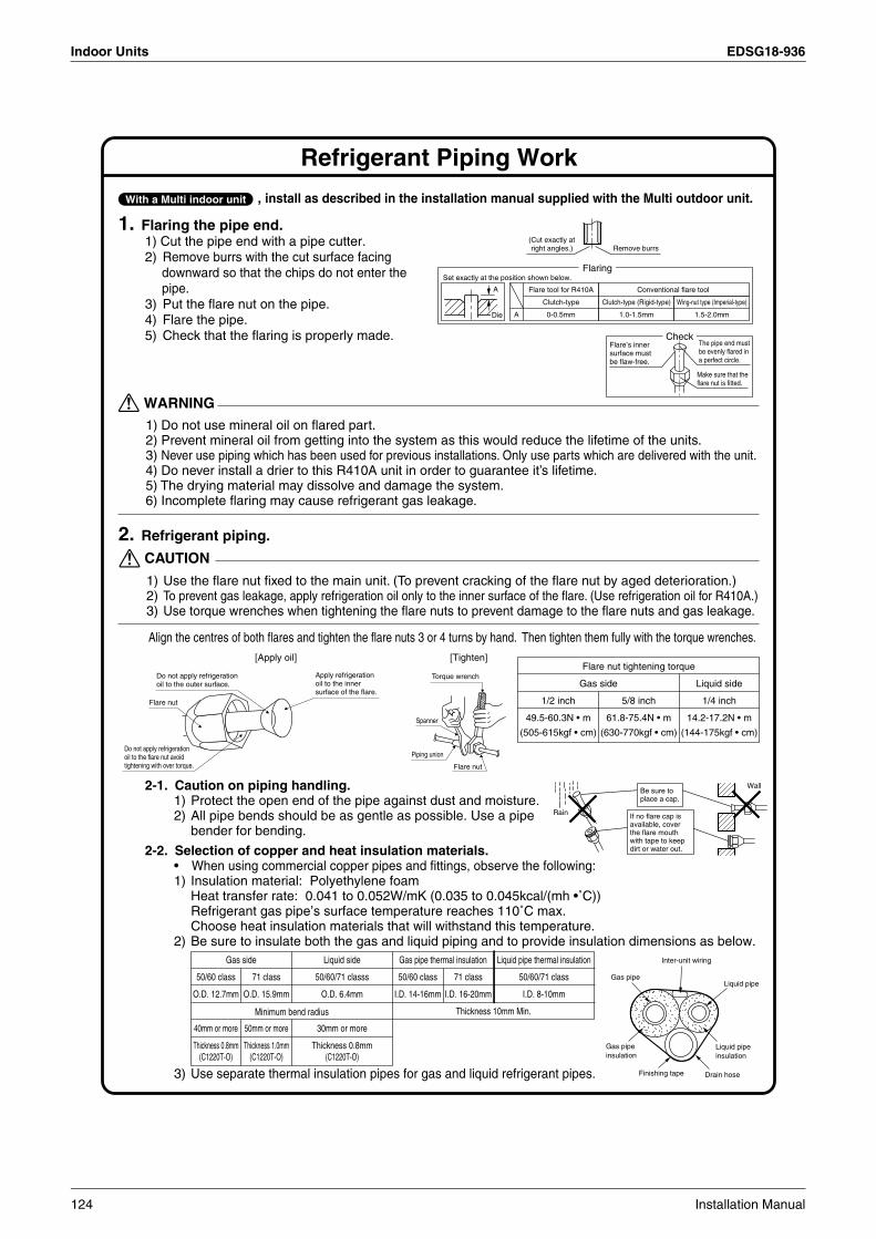
Indoor Units EDSG18-936
Refrigerant Piping Work
2. Refrigerant piping.
2-1. Caution on piping handling.1) Protect the open end of the pipe against dust and moisture.2) All pipe bends should be as gentle as possible. Use a pipe
bender for bending.
2-2. Selection of copper and heat insulation materials.• When using commercial copper pipes and fittings, observe the following:1) Insulation material: Polyethylene foam
Heat transfer rate: 0.041 to 0.052W/mK (0.035 to 0.045kcal/(mh •˚C))Refrigerant gas pipe’s surface temperature reaches 110˚C max.Choose heat insulation materials that will withstand this temperature.
2) Be sure to insulate both the gas and liquid piping and to provide insulation dimensions as below.
1. Flaring the pipe end.1) Cut the pipe end with a pipe cutter.2) Remove burrs with the cut surface facing
downward so that the chips do not enter the pipe.
3) Put the flare nut on the pipe.4) Flare the pipe.5) Check that the flaring is properly made.
1) Do not use mineral oil on flared part.2) Prevent mineral oil from getting into the system as this would reduce the lifetime of the units.3) Never use piping which has been used for previous installations. Only use parts which are delivered with the unit.4) Do never install a drier to this R410A unit in order to guarantee it’s lifetime.5) The drying material may dissolve and damage the system.6) Incomplete flaring may cause refrigerant gas leakage.
WARNING
3) Use separate thermal insulation pipes for gas and liquid refrigerant pipes.
Thickness 10mm Min.
71 class
O.D. 15.9mm
50mm or more
Thickness 1.0mm(C1220T-O)
50/60 class
O.D. 12.7mm
40mm or more
Thickness 0.8mm(C1220T-O)
71 class
I.D. 16-20mm
50/60 class
I.D. 14-16mm
Gas side
Minimum bend radius
Gas pipe thermal insulation
50/60/71 classs
O.D. 6.4mm
30mm or more
Thickness 0.8mm(C1220T-O)
50/60/71 class
I.D. 8-10mm
Liquid side Liquid pipe thermal insulation
, install as described in the installation manual supplied with the Multi outdoor unit.With a Multi indoor unit
Wall
If no flare cap is available, cover the flare mouth with tape to keep dirt or water out.
Be sure to place a cap.
Rain
Gas pipeLiquid pipe
Gas pipe insulation
Liquid pipe insulation
Finishing tape Drain hose
Inter-unit wiring
(Cut exactly at right angles.) Remove burrs
Set exactly at the position shown below.
A
Flaring
Die A 0-0.5mm
Clutch-type
Flare tool for R410A
1.0-1.5mm
Clutch-type (Rigid-type)
1.5-2.0mm
Wing-nut type (Imperial-type)
Conventional flare tool
CheckFlare’s inner surface must be flaw-free.
The pipe end must be evenly flared in a perfect circle.
Make sure that the flare nut is fitted.
1) Use the flare nut fixed to the main unit. (To prevent cracking of the flare nut by aged deterioration.)2) To prevent gas leakage, apply refrigeration oil only to the inner surface of the flare. (Use refrigeration oil for R410A.)3) Use torque wrenches when tightening the flare nuts to prevent damage to the flare nuts and gas leakage.
CAUTION
Align the centres of both flares and tighten the flare nuts 3 or 4 turns by hand. Then tighten them fully with the torque wrenches.
Gas side Liquid side
1/4 inch
14.2-17.2N • m
(144-175kgf • cm)
5/8 inch
61.8-75.4N • m
(630-770kgf • cm)
1/2 inch
49.5-60.3N • m
(505-615kgf • cm)
Flare nut tightening torqueDo not apply refrigeration oil to the outer surface.
Flare nut
Apply refrigeration oil to the inner surface of the flare.
Do not apply refrigeration oil to the flare nut avoid tightening with over torque.
[Apply oil]
Torque wrench
Piping union
Flare nut
Spanner
[Tighten]
124 Installation Manual

EDSG18-936 Indoor Units
3
Trial Operation and Testing
Test items
Incomplete cooling/heating functionNo refrigerant gas leaks.
Draining line is properly installed.
Indoor and outdoor units are installed properly on solid bases.
Refrigerant gas and liquid pipes and indoor drain hose extension are thermally insulated.
Fall, vibration, noise
Water leakage
Water leakage
System is properly earthed. Electrical leakage
Indoor unit properly receives remote controller commands. Inoperative
Indoor or outdoor unit’s air intake or exhaust has clear path of air. Stop valves are opened. Incomplete cooling/heating function
The specified wires are used for inter-unit wiring connections.
Inoperative or burn damage
Symptom(diagnostic display on RC)
Check
1. Trial operation and testing.1-1 Measure the supply voltage and make sure that it falls in the specified range.1-2 Trial operation should be carried out in either cooling mode.• Select the lowest programmable temperature.
1) Trial operation in cooling mode may be disabled depending on the room temperature.Use the remote controller for trial operation as described below.
2) After trial operation is complete, set the temperature to a normal level (26˚C to 28˚C).3) For protection, the system disables restart operation for 3 minutes after it is turned off.
1-3 Carry out the test operation in accordance with the operation manual to ensure that all functions and parts, such as louver movement, are working properly.• The air conditioner requires a small amount of power in its standby mode. If the system is not to be used for
some time after installation, shut off the circuit breaker to eliminate unnecessary power consumption.• If the circuit breaker trips to shut off the power to the air conditioner, the system will restore the original
operation mode when the circuit breaker is opened again.
Trial operation from remote controller.1) Press ON/OFF button to turn on the system.2) Simultaneously press centre of TEMP button and MODE button.3) Press MODE button twice.
(“ ” will appear on the display to indicate that Trial Operation mode is selected.)4) Trial run mode terminates in approx. 30 minutes and switches into normal mode. To quit a trial
operation, press ON/OFF button.
2. Test items.
3P192027-1D
Installation Manual 125

Indoor Units EDSG18-936
3.4 Wall Mounted Type FTKS50B
Accessories
Choosing a Site
Installation Tips
A Mounting plate
E Remote controller holder
F Fixing screws for remote controller holder M3 × 20L
H Indoor unit fixing screwsM4 × 12L
G AAA dry-cell batteries
J Insulation tape
K Operation manual
L Installation manual
1
6
9
2
1
1
2
2
2
1
1
1
D Wireless remote controller
50 class
60, 71 class
C Air purifying filter with photocatalytic deodorizing function
B Mounting platefixing screwsM4 × 25L
1. Indoor unit.• The indoor unit should be sited in a place where:1) the restrictions on installation specified in the indoor unit installation drawings are met,2) both air intake and exhaust have clear paths met,3) the unit is not in the path of direct sunlight,4) the unit is away from the source of heat or steam,5) there is no source of machine oil vapour (this may shorten indoor unit life),6) cool air is circulated throughout the room,7) the unit is away from electronic ignition type fluorescent lamps (inverter or rapid start type) as they may shorten the
remote control range,8) the unit is at least 1 metre away from any television or radio set (unit may cause interference with the picture or sound).
2. Wireless remote controller.1) Turn on all the fluorescent lamps in the room, if any, and find the site where remote control signals are properly
received by the indoor unit (within 7 metres).
1. Removing packaging material• Removal method
Grasp the packaging material which is in the center of the front panel, with one hand, and lightly pull the front panel up and toward you.
2. Removing and installing front panel• Removal method
Hook fingers on the panel protrusions on the left and right of the main body, and open until the panel stops. Slide the front panel sideways to disengagethe rotating shaft. Then pull the front panel toward you to remove it.
• Installation methodAlign the tabs of the front panel with the grooves, and push all the way in. Then close slowly. Push the center of the lower surface of the panel firmly to engage the tabs.
• Before choosing the installation site, obtain user approval.
Push the rotating shaft of the front panel into the groove.
3. Removing and installing front grille• Removal method
1) Remove front panel to remove the air filter.2) Remove the front grille. (50 class 2 screws, 60·71
class 3 screws)3) In front of the mark of the front
grille, there are 3 upper hooks. Lightly pull the front grille toward you with one hand, and push down on the hooks with the fingers of your other hand.
Lightly pull the front grille toward you with one hand, and push down on the hooks with the fingers of your other hand. (3 locations)
Pushdown.
Upper hook
Upper hook
<When there is no work space because the unit is close to ceiling>
Be sure to wear protection gloves.
Caution 1) Push up.
2) Pull toward you.Place both hands under the center of the front grille, and while pushing up, pull it toward you.
• Installation method1) Install the front grille and firmly engage the upper hooks (3 locations).2) Install 2screws(50class)or 3screws(60, 71class)of the front grill.3) Install the air filter and then mount the front panel.
4. How to set the different addressesWhen two indoor units are installed in one room, the two wireless remote controllers can be set for different addresses.1) In the same way as when
connecting to an HA system, remove the metal plate electrical wiring cover.
2) Cut the address jumper (JA).
3) Cut the address jumper (J4).
Addr
ess
JA
AddressJAEXIST 1CUT 2
J4
AddressJ4EXIST 1 CUT 2
mark area (3 locations)
Upper hook
Lightly lift.
Packaging material
Lift the panel slightly and pull out.
126 Installation Manual

EDSG18-936 Indoor Units
3
Indoor Unit Installation Drawings
Wrap the insulation pipe with the finishing tape from bottom to top.
Cut thermal insulation pipe to an appropriate length and wrap it with tape, making sure that no gap is left in the insulation pipe’s cut line.
Caulk pipe hole gap with putty.
30 mm or more from ceiling
Front grille
50 mm or more from walls (on both sides)
M4 × 25L The mounting plate should be installed on a wall which can support the weight of the indoor unit.
A Mounting plate
Service lid
C Air purifying filter with photocatalytic deodorizing function
Tabs (upper 3 locations)
Tabs (upper 3 locations)
Tabs (lower 2 locations)
Tabs (lower 3 locations)
Opening service lidService lid is opening/closing type.Opening method
1) Remove the service lid screws.2) Lift the service lid upward.
Air filters Only for 60 and 71 class units.
50 class
60, 71 class
Insert the upper side of the Air purifying filter with photocatalytic deodorizing function into the tabs (upper 3 locations),push the lower side of the filters up a little and into the tabs (lower 2 locations) (lower 3 locations).
C
Intelligent-eye sensor
The figure shows a 50 class unit. (See Indoor Unit Installation 1. “Installing the mounting plate” for details regarding 60 and 71 class units.)
Intelligent-eye sensor
1) Do not hit or violently push the Intelligent-eye sensor. This can lead to damage and malfunction.2) Do not place large objects near the sensor. Also keep heating units or humidifiers outside the
sensor’s detection area.
Caution
D Wireless remote controller
F (M3 X 20L)
E Remote controller holder
Before screwing the remote control holder to the wall, make sure that control signals are properly received by indoor unit.
Installation Manual 127

Indoor Units EDSG18-936
Indoor Unit Installation1. Installing the mounting plate.
• The mounting plate should be installed on a wall which can support the weight of the indoor unit.1) Temporarily secure the mounting plate to the wall, make sure that the panel is completely level, and mark
the boring points on the wall.2) Secure the mounting plate to the wall with screws.
Recommended mounting-plate retention spots and Dimensions
125
60 83 413.5 44.5
290
52
105099.5
5290
100
100
290
52 5290
55
75 100 98248.5
60
79544.5
125 100
Keep here the piece cut out from the unit for piping
Through-the-wall hole φ80mmDrain hose position
• 60, 71 class
• 50 class
Use tape measure as shown.Position the end of tape measure at ∇
φ80 φ80
* The removed pipe port cover can be kept in the mounting plate pocket.
Recommended mounting - plate retention spots (9 spots in all)
(Bolt size : M10) (Bolt size : M10)
Place a leveler on raised tab.b
Place a leveler on raised tab.
b a
Use tape measure as shown.Position the end of tape measure at ∇
Gas pipe end Liquid pipe end
(Bolt size : M10) (Bolt size : M10)
Dangle a weighted thread and align thread with vertical arrow.
Leveling mounting plate
Recommended mounting - plate retention spots (6 spots in all)
Gas pipe end Liquid pipe end
Through-the-wall hole φ80mmDrain hose position
Removed pipe port cover
A Mounting plate
φ80 φ80
128 Installation Manual
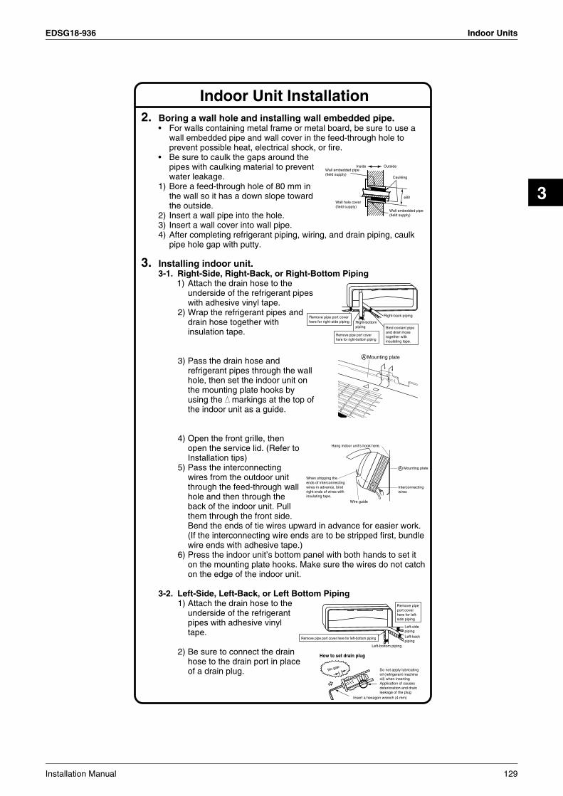
EDSG18-936 Indoor Units
3
Indoor Unit Installation2. Boring a wall hole and installing wall embedded pipe.
• For walls containing metal frame or metal board, be sure to use a wall embedded pipe and wall cover in the feed-through hole to prevent possible heat, electrical shock, or fire.
• Be sure to caulk the gaps around the pipes with caulking material to prevent water leakage.
1) Bore a feed-through hole of 80 mm in the wall so it has a down slope toward the outside.
2) Insert a wall pipe into the hole.3) Insert a wall cover into wall pipe.4) After completing refrigerant piping, wiring, and drain piping, caulk
pipe hole gap with putty.
3. Installing indoor unit.3-1. Right-Side, Right-Back, or Right-Bottom Piping
1) Attach the drain hose to the underside of the refrigerant pipes with adhesive vinyl tape.
2) Wrap the refrigerant pipes and drain hose together with insulation tape.
3) Pass the drain hose and refrigerant pipes through the wall hole, then set the indoor unit on the mounting plate hooks by using the markings at the top of the indoor unit as a guide.
4) Open the front grille, then open the service lid. (Refer to Installation tips)
5) Pass the interconnecting wires from the outdoor unit through the feed-through wall hole and then through the back of the indoor unit. Pull them through the front side. Bend the ends of tie wires upward in advance for easier work. (If the interconnecting wire ends are to be stripped first, bundle wire ends with adhesive tape.)
6) Press the indoor unit’s bottom panel with both hands to set it on the mounting plate hooks. Make sure the wires do not catch on the edge of the indoor unit.
3-2. Left-Side, Left-Back, or Left Bottom Piping1) Attach the drain hose to the
underside of the refrigerant pipes with adhesive vinyl tape.
2) Be sure to connect the drain hose to the drain port in place of a drain plug.
Inside Outside
Caulking
Wall embedded pipe (field supply)
Wall hole cover(field supply)
Wall embedded pipe (field supply)
φ80
Right-bottom piping
Right-back piping
Bind coolant pipe and drain hose together with insulating tape.
Remove pipe port cover here for right-side piping
Remove pipe port cover here for right-bottom piping
Mounting plateA
Wire guide
When stripping the ends of interconnecting wires in advance, bind right ends of wires with insulating tape.
Hang indoor unit’s hook here.
Interconnectingwires
Mounting plateA
Remove pipe port cover here for left-bottom piping
Remove pipe port cover here for left-side piping
Left-bottom piping
Left-side pipingLeft-back piping
How to set drain plug
No gapDo not apply lubricating oil (refrigerant machine oil) when insertingApplication of causes deterioration and drain leakage of the plug
Insert a hexagon wrench (4 mm)
Installation Manual 129

Indoor Units EDSG18-936
Indoor Unit Installation3) Shape the refrigerant pipe along the pipe path marking on the
mounting plate.4) Pass drain hose and refrigerant pipes through the wall hole,
then set the indoor unit on mounting plate hooks, using the markings at the top of indoor unit as a guide.
5) Pull in the interconnecting wires.6) Connect the inter-unit piping.7) Wrap the refrigerant pipes and drain hose together with insulation
tape as right figure, in case of setting the drain hose through the back of the indoor unit.
8) While exercising care so that the interconnecting wires do not catch indoor unit, press the bottom edge of indoor unit with both hands until it is firmly caught by the mounting plate hooks. Secure indoor unit to the mounting plate with screws (M4 × 12L).
3-3. Wall Embedded PipingFollow the instructions given under
1) Insert the drain hose to this depth so it wont be pulled out of the drain pipe.
4. Wiring.1) Strip wire ends (15 mm).2) Match wire colours with terminal
numbers on indoor and outdoor unit’s terminal blocks and firmly screw wires to the corresponding terminals.
3) Connect the earth wires to the corresponding terminals.
4) Pull wires to make sure that they are securely latched up, then retain wires with wire retainer.
5) In case of connecting to an adapter system. Run the remote control cable and attach the S21 connector as the illustration above.
6) Shape the wires so that the service lid fits securely, then close service lid.
Wrap insulating tape around the bent portion of refrigerant pipe. Overlap at least half the width of the tape with each turn.
Drain hose
Caulk this hole with putty or caulking material. Bind with plastic
tape.
A Mounting plate
Refrigerantpipes
Drain hose
Bottom frame
H M4 × 12L (2 point)
Mountingplate
A
Left-Side, Left-Back, or Left Bottom PipingInner wall
Vinyl chloride drain pipe (VP-30)
Drain hose50 mm or more
Insert drain hose to this depth so it won’t be pulled out of drain pipe.
Outer wall
Shape wires so that the service lid will fit securely.
Terminal blockElectrical component box
Wire retainerFirmly secure wire retainer so that wires sustain no external stress.
Use the specified wire type.
123
1 2 3 L N
Safety breaker 20A
Earth leakage circuit breaker
Earth
When wire length exceeds 10 m, use 2.0-mm wires.
H05VV
Firmly fix the wires with the terminal screws.
Outdoor unit
Indoor unit
Powersupply50Hz 220V - 240V60Hz 220V - 230VFirmly fix the wires with
the terminal screws.
Do not use tapped wires, stand wires, extensioncords, or starbust connections, as they may cause overtheating, electrical shock,or fire.
Warning
130 Installation Manual

EDSG18-936 Indoor Units
3
5. When connecting to an HA system.1) Remove the front grille. (50 class 2 screws, 60·71 class 3 screws)2) Remove the electrical wiring box. (1 screw)3) Remove the metal plate electrical wiring cover. (4 tabs)4) Attach the connection cord to the S21 connector and pull the
harness out through the notched part in the figure.5) Replace the electrical wiring cover as it was, and pull the harness
around, as shown in the figure
Screw
HA cord
HA connector(S21)
Tab
TabPush
Slide
Push
Metal plate electrical cover
Tab
Push
Main body
Notched part
4) 5) Replace the electrical wiring cover as it was, and pull the harness around, as shown in the figure.
Attach the connection cord to the S21 connector and pull the harness out through the notched part in the figure.
3) Remove the metal plate electrical wiring cover.
6. Drain piping.1) Connect the drain hose, as described
below.
2) Remove the air filters and pour some water into the drain pan to check the water flows smoothly.
3) When drain hose requires extension, obtain an extension hose commercially available.Be sure to thermally insulate the indoor section of the extension hose.
4) When connecting a rigid polyvinyl chloride pipe (nominal diameter 13 mm) directly to the drain hose attached to the indoor unit as with embedded piping work, use any commercially available drain socket (nominal diameter 13 mm) as a joint.
The drain hose should be inclined downward.
No trap is permitted.
Do not put the end of the hose in water.
Indoor unit drain hose φ
18 Extension drain hose
Heat insulation tube(Field supply)
Drain hose supplied with the indoor unit
Commercially available drain socket (nominal diameter 13 mm)
Commercially available rigid polyvinyl chloride pipe(nominal diameter 13 mm)
φ 18
Indoor Unit Installation
Installation Manual 131
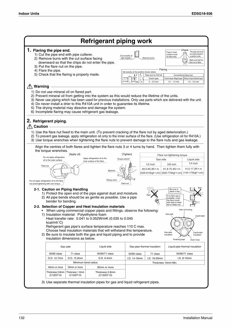
Indoor Units EDSG18-936
1. Flaring the pipe end.1) Cut the pipe end with pipe cutterer.2) Remove burrs with the cut surface facing
downward so that the chips do not enter the pipe.3) Put the flare nut on the pipe.4) Flare the pipe.5) Check that the flaring is properly made.
2. Refrigerant piping.
2-1. Caution on Piping Handling1) Protect the open end of the pipe against dust and moisture.2) All pipe bends should be as gentle as possible. Use a pipe
bender for bending.
2-2. Selection of Copper and Heat Insulation materials• When using commercial copper pipes and fittings, observe the following:1) Insulation material: Polyethylene foam
Heat transfer rate: 0.041 to 0.052W/mK (0.035 to 0.045 kcal/mh˚C)Refrigerant gas pipe’s surface temperature reaches 110 C max.Choose heat insulation materials that will withstand this temperature.
2) Be sure to insulate both the gas and liquid piping and to provide insulation dimensions as below.
3) Use separate thermal insulation pipes for gas and liquid refrigerant pipes.
Wall
If no flare cap is available, cover the flare mouth with tape to keep dirt or water out.
Be sure to place a cap.
Rain
Gas pipeLiquid pipe
Gas pipe insulation
Liquid pipe insulation
Finishing tape Drain hose
Inter-unit wiring
Gas side
Minimum bend radius
Liquid side Gas pipe thermal insulation Liquid pipe thermal insulation
50/60 class
O.D. 12.7mm
40mm or more
Thickness 0.8mm(C1220T-O)
71 class
O.D. 15.9mm
50mm or more
Thickness 1.0mm(C1220T-O)
50/60/71 class
O.D. 6.4mm
50/60 class
I.D. 14-16mm
71 class
I.D. 16-20mm
50/60/71 class
I.D. 8-10mm
Thickness 10mm Min.
30mm or more
Thickness 0.8mm(C1220T-O)
1) Do not use mineral oil on flared part.2) Prevent mineral oil from getting into the system as this would reduce the lifetime of the units.3) Never use piping which has been used for previous installations. Only use parts which are delivered with the unit.4) Do never install a drier to this R410A unit in order to guarantee its lifetime.5) The drying material may dissolve and damage the system.6) Incomplete flaring may cause refrigerant gas leakage.
Warning
1) Use the flare nut fixed to the main unit. (To prevent cracking of the flare nut by aged deterioration.)2) To prevent gas leakage, apply refrigeration oil only to the inner surface of the flare. (Use refrigeration oil for R410A.)3) Use torque wrenches when tightening the flare nuts to prevent damage to the flare nuts and gas leakage.
Caution
Set exactly at the position shown below.
A
Flaring
Die A 0 ~ 0.5 mm
Clutch-type
Flare tool for R410A
1.0 ~ 1.5 mm
Clutch-type (Rigid-type)
1.5 ~ 2.0 mm
Wing-nut type (Imperial-type)
Conventional flare tool
Flare nut tightening torque
14.2-17.2N • m
(144-175kgf • cm)
1/4 inch
61.8-75.4N • m
(630-770kgf • cm)
5/8 inch
49.5-60.3N • m
(505-615kgf • cm)
1/2 inch
Gas side Liquid side
Align the centres of both flares and tighten the flare nuts 3 or 4 turns by hand. Then tighten them fully with the torque wrenches.
Torque wrench
Piping union
Flare nut
Do not apply refrigeration
oil to the outer surface.
Flare nut
Apply refrigeration oil to the
inner surface of the flare.
Do not apply refrigeration oil to the flare
nut avoid tightening with over torque.
Spanner
[Apply oil] [Tighten]
Refrigerant piping work
(Cut exactly at right angles.) Remove burrs
CheckFlare’s inner surface must be flaw-free.
The pipe end must be evenly flared in a perfect circle.
Make sure that the flare nut is fitted.
132 Installation Manual

EDSG18-936 Indoor Units
3
1. Trial Operation and Testing.1-1 Measure the supply voltage and make sure that it falls in the specified range.1-2 Trial operation should be carried out in either cooling or heating mode.
For Heat pump• In cooling mode, select the lowest programmable temperature; in heating mode, select the highest
programmable temperature.1) Trial operation may be disabled in either mode depending on the room temperature.2) After trial operation is complete, set the temperature to a normal level (26˚C to 28˚C in cooling mode, 20˚C
to 24˚C in heating mode).3) For protection, the system disables restart operation for 3 minutes after it is turned off.
For Cooling only• Select the lowest programmable temperature.
1) Trial operation in cooling mode may be disabled depending on the room temperature.Use the remote control for trial operation as described below.
2) After trial operation is complete, set the temperature to a normal level (26˚C to 28˚C).3) For protection, the system disables restart operation for 3 minutes after it is turned off.
1-3 Carry out the test operation in accordance with the Operation Manual to ensure that all functions and parts, such as louver movement, are working properly.• The air conditioner requires a small amount of power in its standby mode. If the system is not to be used for
some time after installation, shut off the circuit breaker to eliminate unnecessary power consumption.• If the circuit breaker trips to shut off the power to the air conditioner, the system will restore the
original operation mode when the circuit breaker is opened again.
2. Trial Operation from Remote Controller.1) Press ON/OFF button to turn on the system.2) Simultaneously press centor of TEMP button and MODE button.3) Press MODE button twice.
(“ ” will appear on the display to indicate that Trial Operation mode is selected.)4) Trial run mode terminates in approx. 30 minutes and switches into normal mode. To quit a trial
operation, press ON/OFF button.
3. Test Items.
Test Items
Incomplete cooling/heating functionNo refrigerant gas leaks.
Draining line is properly installed.
Indoor and outdoor units are installed properly on solid bases.
Refrigerant gas and liquid pipes and indoor drain hose extension are thermally insulated.
Fall, vibration, noise
Water leakage
Water leakage
System is properly earthed. Electrical leakage
Indoor unit properly receives remote control commands. Inoperative
Indoor or outdoor unit’s air intake or exhaust has clear path of air. Shut-off valves are opened. Incomplete cooling/heating function
The specified wires are used for interconnecting wire connections.
Inoperative or burn damage
Symptom(diagnostic display on RC)
Check
Trial Operation and Testing
3P098801-18R
Installation Manual 133

Indoor Units EDSG18-936
3.5 Duct Connected Type FDKS25/35CA
2
ACCESSORIES
CHOOSING A SITE• Before choosing the installation site, obtain user approval.
Caution• When moving the unit during or after unpacking, make sure to lift it by holding its lifting lugs. Do not exert any pressure on
other parts, especially the refrigerant piping, drain piping and flange parts.Wear protective gears (gloves and so on) when installing the unit.
• If you think the humidity inside the ceiling might exceed 30°C and RH80%, reinforce the insulation on the unit body.Use glass wool or polyethylene foam as insulation so that the thickness is more than 10mm and fits inside the ceiling opening.
• Optimum air distribution is ensured.• The air passage is not blocked.• Condensate can drain properly.• The ceiling is strong enough to bear the weight of the indoor unit.• A false ceiling does not seem to be at an incline.• Sufficient clearance for maintenance and servicing is ensured.• Piping between the indoor and outdoor units is within the allowable limits.
(Refer to the installation manual for the outdoor unit.)• The indoor unit, outdoor unit, power supply wiring and transmission wiring is at least 1
meter away from televisions and radios. This prevents image interference and noise in electrical appliances. (Noise may be generated depending on the conditions under which the electric wave is generated, even if a one-meter allowance is maintained.)
Use suspension bolts to install the unit. Check whether or not the ceiling is strong enough to support the weight of the unit. If there is a risk that the ceiling is not strong enough, reinforce the ceiling before installing the unit.(Installation pitch is marked on the carton box for installation. Refer to it to check for points requiring reinforcing.) Select the *H dimension such that a downward slope of at least 1/100 is ensured as indicated in “DRAIN PIPING WORK”.• The installation pitch is listed on the packing material, and should be
checked when deciding whether to reinforce the location or not.
Wirelessremote controller
1 pc.
AAAdry-cell batteries
Remote controllerholder
1 pc.1 pc.
Air fillter
1 set
2 pcs.
[ Other ]
• Operation manual
• Installation manual
Clamp metal
1 pc. 1 pc.
Insulationfor fitting
1 each
Sealing pad
Large and small1 each
for gas pipe
for liquid pipe
Large
Small 24 pcs.
Washer for hanging bracket
8 pcs. 2 pcs. 6 pcs.
4 pcs.
Drain hose Sealingmaterial Clamp Washer
fixing plate
1 set1 set
Screws for duct flanges
Stored in outlet vent
1 pc.
2 large
1 smallHanger (right)insulation
Mounting frameScrews M4 × 25
Decorative cover
1 pc.
Receiver kit
1 pc. 2 pcs.
3 pcs.(only for 50-60 type)
134 Installation Manual
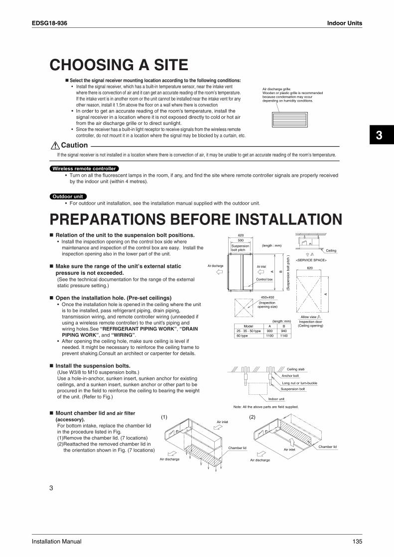
EDSG18-936 Indoor Units
3
3
CHOOSING A SITESelect the signal receiver mounting location according to the following conditions:• Install the signal receiver, which has a built-in temperature sensor, near the intake vent
where there is convection of air and it can get an accurate reading of the room’s temperature. If the intake vent is in another room or the unit cannot be installed near the intake vent for any other reason, install it 1.5m above the floor on a wall where there is convection.
• In order to get an accurate reading of the room’s temperature, install the signal receiver in a location where it is not exposed directly to cold or hot air from the air discharge grille or to direct sunlight.
• Since the receiver has a built-in light receptor to receive signals from the wireless remote controller, do not mount it in a location where the signal may be blocked by a curtain, etc.
CautionIf the signal receiver is not installed in a location where there is convection of air, it may be unable to get an accurate reading of the room’s temperature.
• Turn on all the fluorescent lamps in the room, if any, and find the site where remote controller signals are properly receivedby the indoor unit (within 4 metres).
• For outdoor unit installation, see the installation manual supplied with the outdoor unit.
PREPARATIONS BEFORE INSTALLATIONRelation of the unit to the suspension bolt positions. • Install the inspection opening on the control box side where
maintenance and inspection of the control box are easy. Install the inspection opening also in the lower part of the unit.
Make sure the range of the unit’s external static pressure is not exceeded.(See the technical documentation for the range of the external static pressure setting.)
Open the installation hole. (Pre-set ceilings)• Once the installation hole is opened in the ceiling where the unit
is to be installed, pass refrigerant piping, drain piping, transmission wiring, and remote controller wiring (unneeded if using a wireless remote controller) to the unit’s piping and wiring holes.See “REFRIGERANT PIPING WORK”, “DRAIN PIPING WORK”, and “WIRING”.
• After opening the ceiling hole, make sure ceiling is level if needed. It might be necessary to reinforce the ceiling frame to prevent shaking.Consult an architect or carpenter for details.
Install the suspension bolts.(Use W3/8 to M10 suspension bolts.)Use a hole-in-anchor, sunken insert, sunken anchor for existing ceilings, and a sunken insert, sunken anchor or other part to be procured in the field to reinforce the ceiling to bearing the weight of the unit. (Refer to Fig.)
Mount chamber lid and air filter (accessory).For bottom intake, replace the chamber lid in the procedure listed in Fig.(1)Remove the chamber lid. (7 locations)(2)Reattached the removed chamber lid in
the orientation shown in Fig. (7 locations)
BA
620
500
450×450
(Inspectionopening size)
Air discharge
Suspensionbolt pitch
(length : mm)
Air inlet
Control box
(Sus
pens
ion
bolt
pitc
h )
Ceiling
620
A
Allow view Inspection door
(Ceiling opening)
<SERVICE SPACE>
Model25 · 35 · 50 type60 type
A900
1100
B940
1140
(length: mm)
Installation Manual 135

Indoor Units EDSG18-936
4
(3)Attach sealing pad as shown in the figure below. (Stored in outlet vent)(In order to take in the air inside the ceiling, and when not taking in air from outdoor air, it is not necessary to stick.)• Attach the sealing pad (accessory) to
the plate metal sections which are not covered by anti-sweat material.
• Make sure there are no gaps between the different pieces of sealing pad.
(4)Attach the hanger (right) insulation to the right hanger. (Stored in outlet vent)(See the below figure for the sticking base line.)
(5)Attach the air filter (accessory) in the manner shown in the diagram.
When two indoor units are installed in one room, one of the two wireless remote controllers can be easily set for another addresses.
136 Installation Manual

EDSG18-936 Indoor Units
3
5
INDOOR UNIT INSTALLATION⟨⟨ As for the parts to be used for installation work, be sure to use the provided accessories and specified parts
designated by our company. ⟩⟩
Install the indoor unit temporarily.• Attach the hanger bracket to the suspension bolt. Be sure to fix
it securely by using a nut and washer from the upper and lower sides of the hanger bracket. (Refer to Fig.)
[ PRECAUTION ]Since the unit uses a plastic drain pan, prevent welding spatter and other foreign substances from entering the outlet hole during installation.
Adjust the height of the unit.
Check the unit is horizontally level.
CautionMake sure the unit is installed level using a level or a plastic tube filled with water. In using a plastic tube instead of a level, adjust the top surface of the unit to the surface of the water at both ends of the plastic tube and adjust the unit horizontally. (One thing to watch out for in particular is if it is installed so that the slope is not in the direction of the drain piping, as this might cause leaking.)
Tighten the upper nut.
Mounting the receiver.Mount the receiver as shown below.
OUTDOOR UNIT INSTALLATION Install as described in the installation manual supplied with the outdoor unit.
1 Press the receiver into the mounting frame.
2 Mount the completed assembly using two screws.
3 Press the decorative cover into the mounting frame.
Note) Mount the Remote controller cord far enough away from strong electrical wires (such as distribution wires for electrical lights, air conditioners, etc.) and from weak electrical wires (such as wires for telephones, intercoms, etc.).
Installation Manual 137

Indoor Units EDSG18-936
6
REFRIGERANT PIPING WORK See the installation manual supplied with the outdoor unit.
1. FLARING THE PIPE END1) Cut the pipe end with a pipe cutter.2) Remove burrs with the cut surface facing downward
so that the chips do not enter the pipe.3) Put the flare nut on the pipe.4) Flare the pipe.5) Check that the flaring is properly made.
WarningDo not use mineral oil on flared part.Prevent mineral oil from getting into the system as this would reduce the lifetime of the units.Never use piping which has been used for previous installations. Only use parts which are delivered with the unit.Do never install a drier to this R410A unit in order to guarantee its lifetime.The drying material may dissolve and damage the system.Incomplete flaring may cause refrigerant gas leakage.
2. REFRIGERANT PIPING1) To prevent gas leakage, apply refrigeration machine oil on both
inner and outer surfaces of the flare. (Use refrigeration oil for R410A)
2) Align the centres of both flares and tighten the flare nuts 3 or 4 turns by hand. Then tighten them fully with the torque wrenches. • Use torque wrenches when tightening the flare nuts to prevent
damage to the flare nuts and escaping gas.
CautionOvertightening may damage the flare and cause leaks.
Flare nut tightening torque
Gas side Liquid side
3/8 inch 1/2 inch 1/4 inch
32.7~39.9N•m(333~407kgf•cm)
49.5~60.3N•m(505~615kgf•cm)
14.2~17.2N•m(144~175kgf•cm)
138 Installation Manual

EDSG18-936 Indoor Units
3
7
REFRIGERANT PIPING WORK 3) After the work is finished, make sure to check that there is no
gas leak.
4) After checking for gas leaks, be sure to insulate the pipe connections.• Insulate using the insulation for fitting included with the liquid and gas pipes. Besides, make sure the insulation for fitting
on the liquid and gas piping has its seams facing up.(Tighten both edges with clamp.)
• For the gas piping, wrap the medium sealing pad over the insulation for fitting (flare nut part).
CautionBe sure to insulate any field piping all the way to the piping connection inside the unit. Any exposed piping may cause condensation or burns if touched.
Cautions on Pipe Handling• Protect the open end of the pipe against dust and moisture.
(Tighten both edges with clamp.)• All pipe bends should be as gentle as possible. Use a pipe bender for
bending.(Bending radius should be 30 to 40 mm or larger.)
Selection of Copper and Heat Insulation materialsWhen using commercial copper pipes and fittings, observe the following:• Insulation material: Polyethylene foam
Heat transfer rate: 0.041 to 0.052W/mK (0.035 to 0.045 kcal/mh°C)Refrigerant gas pipe’s surface temperature reaches 110°C max.Choose heat insulation materials that will withstand this temperature.
• Be sure to insulate both the gas and liquid piping and to provide insulation dimensions as below.
Also, when subject to high humidity, heat insulation of the refrigerant piping (the unit piping and branch piping) must be further reinforced.Reinforce the insulation when installing the unit near bathrooms, kitchens, and other similar locations.Refer to the following:
• 30°C, more than 75% RH: 20 mm Min. in thicknessIf the insulation is not sufficient, condensation may form on the surface of the insulation.
• Use separate thermal insulation pipes for gas and liquid refrigerant pipes.
Installation Manual 139

Indoor Units EDSG18-936
≤
8
DRAIN PIPING WORKCaution
Make sure all water is out before making the duct connection.
Install the drain piping.• Make sure the drain works properly.• The diameter of the drain pipe should be greater than or equal to the
diameter of the connecting pipe (vinyl tube; pipe size: 20 mm; outer dimension: 26 mm).
• Keep the drain pipe short and sloping downwards at a gradient of at least 1/100 to prevent air pockets from forming.
CautionWater accumulating in the drain piping can cause the drain to clog.
• To keep the drain tube from sagging, space hanging wires every 1 to 1.5 m.• Use the drain hose and the metal clamp. Insert the drain hose fully into the drain socket and firmly tighten the metal clamp with
the upper part of the tape on the hose end. Tighten the metal clamp until the screw head is less than 4 mm from the hose.• The two areas below should be insulated because condensation may form there causing water to leak.
• Drain piping passing indoors• Drain sockets
Referring the figure below, insulate the metal clamp and drain hose using the included large sealing pad.
⟨ PRECAUTIONS ⟩Drain piping connections• Do not connect the drain piping directly to sewage pipes that smell of ammonia. The ammonia in the sewage might enter the
indoor unit through the drain pipes and corrode the heat exchanger.• Do not twist or bend the drain hose, so that excessive force is not applied to it.
(This type of treatment may cause leaking.)
After piping work is finished, check drainage flows smoothly.• Gradually insert approximately 1,000 cc of water into the drain pan to
check drainage in the manner described below.• Gradually pour approximately 1,000 cc of water from the outlet
hole into the drain pan to check drainage.• Check the drainage.
Clamp metal
Drain hoseTape
(attached)
4mm
Large sealing pad
Clamp metal
(attached)
(attached)
140 Installation Manual

EDSG18-936 Indoor Units
3
9
INSTALLING THE DUCTConnect the duct supplied in the field.Air inlet side
• Attach the duct and intake-side flange (field supply).• Connect the flange to the main unit with accessory screws (in 20 or 24 positions).• Wrap the intake-side flange and duct connection area with aluminum tape or something similar to prevent air escaping.
CautionWhen attaching a duct to the intake side, be sure also to attach an air filter inside the air passage on the intake side. (Use an air filter whose dust collecting efficiency is at least 50% in a gravimetric technique.)
Outlet side• Connect the duct according to the inside of the outlet-side flange.• Wrap the outlet-side flange and the duct connection area with aluminum tape or something similar to prevent air escaping.
Caution• Be sure to insulate the duct to prevent condensation from forming. (Material: glass wool or polyethylene foam, 25 mm thick)• Use electric insulation between the duct and the wall when using metal ducts to pass metal laths of the net or fence shape or
metal plating into wooden buildings.
Installation Manual 141

Indoor Units EDSG18-936
10
WIRINGSee the installation manual supplied with the outdoor unit.
HOW TO CONNECT WIRINGS. • Wire only after removing the control box lid as shown in the Fig.
Caution• When clamping the wiring, use the included clamping material as shown in the Fig. to prevent outside pressure being exerted
on the wiring connections and clamp firmly.• When doing the wiring, make sure the wiring is neat and does not cause the control box lid to stick up, then close the cover
firmly. When attaching the control box lid, make sure you do not pinch any wires.• Outside the machine, separate the weak wiring (remote controller wiring) and strong wiring (earth wire and power supply wiring) at least
50 mm so that they do not pass through the same place together. Proximity may cause electrical interference, malfunctions, and breakage.
[ PRECAUTIONS ] • See also the “Electrical Wiring Diagram Nameplate” when wiring the unit for electrical power.
[ Connecting electrical wiring ]
• Power supply wiring and Earth wireRemove the control box lid.Next, pull the wires into the unit through the wiring through hole and connect to the power wiring terminal block (4P).
WarningDo not use tapped wires, stand wires, extensioncords, or starbust connections, as they may cause overheating, electrical shock, or fire.
• Make sure to let a wire go through a wire penetration area.• After wiring, seal the wire and wire penetration area to prevent moisture and small creatures from the outside.
• Wrap the strong and weak electric lines with the sealing material as shown in the figure below.(Otherwise, moisture or small creatures such as insects from the outside may cause short-circuit inside the control box.)Attach securely so that there are no gaps.
Insideunit
Outsideunit
[How to adhere it]
Wire
(attached)Sealing material Wiring
through hole
Wiring
Clasp
(Control box side)
(Power supply side)
Clamp(for fixing in place) (attached)
∗Remote controller wiring
Power supply wiringEarth wire
Control box lid
Wiring Diagram(Rear)
Terminal block (4P)
Wiring through hole
Power supply wiringEarth wire
Power supply wiringEarth wire
Clamp (for fixing in place)
(attached)
Indoor PCboard(ASSY)
142 Installation Manual

EDSG18-936 Indoor Units
3
11
TRIAL OPERATION AND TESTING(1) Measure the supply voltage and make sure that it falls in the specified range.(2) Trial operation should be carried out in either cooling or heating mode.
For Heat pump.In cooling mode, select the lowest programmable temperature; in heating mode, select the highest programmable temperature.
• Trial operation may be disabled in either mode depending on the room temperature.• After trial operation is complete, set the temperature to a normal level (26°C to 28°C in cooling mode, 20°C to 24°C in
heating mode).• For protection, the system disables restart operation for 3 minutes after it is turned off.
For Cooling only.Select the lowest programmable temperature.
• Trial operation in cooling mode may be disabled depending on the room temperature.Use the remote control for trial operation as described below.
• After trial operation is complete, set the temperature to a normal level (26°C to 28°C).• For protection, the unit disables restart operation for 3 minutes after it is turned off.
(3) Carry out the test operation in accordance with the Operation Manual to ensure that all functions and parts, are working properly.* The air conditioner requires a small amount of power in its standby mode. If the system is not to be used for some time after
installation, shut off the circuit breaker to eliminate unnecessary power consumption.* If the circuit breaker trips to shut off the power to the air conditioner, the system will restore the original operation mode when
the circuit breaker is turned on again.
3P132003-2N
Installation Manual 143

Indoor Units EDSG18-936
3.6 Duct Connected Type FDKS50/60C, FDKS25/35EA
2
ACCESSORIES
CHOOSING A SITE• Before choosing the installation site, obtain user approval.
Caution• When moving the unit during or after unpacking, make sure to lift it by holding its lifting lugs. Do not exert any pressure on
other parts, especially the refrigerant piping, drain piping and flange parts.Wear protective gears (gloves and so on) when installing the unit.
• If you think the humidity inside the ceiling might exceed 30˚C and RH80%, reinforce the insulation on the unit body.Use glass wool or polyethylene foam as insulation so that the thickness is more than 10mm and fits inside the ceiling opening.
• Optimum air distribution is ensured.• The air passage is not blocked.• Condensate can drain properly.• The ceiling is strong enough to bear the weight of the indoor unit.• A false ceiling does not seem to be at an incline.• Sufficient clearance for maintenance and servicing is ensured.• Piping between the indoor and outdoor units is within the allowable limits.
(Refer to the installation manual for the outdoor unit.)• The indoor unit, outdoor unit, power supply wiring and transmission wiring is at least
1 meter away from televisions and radios. This prevents image interference and noise in electrical appliances. (Noise may be generated depending on the conditions under which the electric wave is generated, even if a one-meter allowance is maintained.)
Use suspension bolts to install the unit. Check whether or not the ceiling is strong enough to support the weight of the unit. If there is a risk that the ceiling is not strong enough, reinforce the ceiling before installing the unit. (Installation pitch is marked on the carton box for installation. Refer to it to check for points requiring reinforcing.) Select the *H dimension such that a downward slope of at least 1/100 is ensured as indicated in “DRAIN PIPING WORK”.• The installation pitch is listed on the packing material, and should be
checked when deciding whether to reinforce the location or not.
Wireless remote controller
1 pc.
AAA dry-cell batteries
Mounting frameScrews M4 × 25
Decorative cover
Remote controllerholder
1 pc.1 pc. 1 pc.
Receiver kitAir fillter
1 set 1 pc. 2 pcs. [ Other ]
• Operation manual
Installation manual
2 pcs.
Clamp metal
1 pc. 1 pc.
Insulation for fitting
1 each
Sealing pad
Large and small1 each
for gas pipe
for liquid pipe
Large
Small 24 pcs.4 pcs.
Washer for hanging bracket
8 pcs. 2 pcs. 6 pcs. 1 set
Drain hose Sealingmaterial Clamp Washer
fixing plate
1 set
Screws for duct flanges
Stored in outlet vent
3 pcs.(only for 50-60 type) 1 pc.
2 large
1 smallHanger (right)insulation
Indoor unit
Control box Maintenancespace
300or more
20 or more
2500
or m
ore
*H=
240
or m
ore
200
Ceiling
Floor surface
(length : mm)
If th
ere
is
no c
eilin
g
144 Installation Manual

EDSG18-936 Indoor Units
3
3
CHOOSING A SITESelect the signal receiver mounting location according to the following conditions:• Install the signal receiver, which has a built-in temperature sensor, near the intake vent
where there is convection of air and it can get an accurate reading of the room’s temperature. If the intake vent is in another room or the unit cannot be installed near the intake vent for any other reason, install it 1.5m above the floor on a wall where there is convection.
• In order to get an accurate reading of the room’s temperature, install the signal receiver in a location where it is not exposed directly to cold or hot air from the air discharge grille or to direct sunlight.
• Since the receiver has a built-in light receptor to receive signals from the wireless remote controller, do not mount it in a location where the signal may be blocked by a curtain, etc.
CautionIf the signal receiver is not installed in a location where there is convection of air, it may be unable to get an accurate reading of the room’s temperature.
• Turn on all the fluorescent lamps in the room, if any, and find the site where remote controller signals are properly received by the indoor unit (within 4 metres).
• For outdoor unit installation, see the installation manual supplied with the outdoor unit.
PREPARATIONS BEFORE INSTALLATIONRelation of the unit to the suspension bolt positions. • Install the inspection opening on the control box side where
maintenance and inspection of the control box are easy. Install the inspection opening also in the lower part of the unit.
Make sure the range of the unit’s external static pressure is not exceeded.(See the technical documentation for the range of the external static pressure setting.)
Open the installation hole. (Pre-set ceilings)• Once the installation hole is opened in the ceiling where the unit
is to be installed, pass refrigerant piping, drain piping, transmission wiring, and remote controller wiring (unneeded if using a wireless remote controller) to the unit’s piping and wiring holes.See “REFRIGERANT PIPING WORK”, “DRAIN PIPING WORK”, and “WIRING”.
• After opening the ceiling hole, make sure ceiling is level if needed. It might be necessary to reinforce the ceiling frame to prevent shaking.Consult an architect or carpenter for details.
Install the suspension bolts.(Use W3/8 to M10 suspension bolts.)Use a hole-in-anchor, sunken insert, sunken anchor for existing ceilings, and a sunken insert, sunken anchor or other part to be procured in the field to reinforce the ceiling to bearing the weight of the unit. (Refer to Fig.)
Air discharge grille: Wooden or plastic grille is recommended because condensation may occur depending on humidity conditions.
Wireless remote controller
Outdoor unit
BA
620
500
450×450
(Inspection opening size)
Air discharge
Suspensionbolt pitch
(length : mm)
Air inlet
Control box(S
uspe
nsio
n bo
lt pi
tch
)
Ceiling
620
AAllow view
Inspection door(Ceiling opening)
⟨SERVICE SPACE⟩
Model25 · 35 type
50 type60 type
A700900
1100
B740940
1140
(length: mm)
Note: All the above parts are field supplied.
Suspension bolt
Long nut or turn-buckle
Anchor bolt
Indoor unit
Ceiling slab
Installation Manual 145

Indoor Units EDSG18-936
4
Mount chamber lid and air filter (accessory).For bottom intake, replace the chamber lid and the protection net (only for 25-35 type) in the procedure listed in Fig.(1)Remove the protection net.
(only for 25-35 type, 6 locations)Remove the chamber lid. (7 locations)
(2)Reattach the removed chamber lid in the orientation shown in Fig.(7 locations)Reattach the removed protection net in the orientation shown in Fig. (only for 25-35 type, 6 locations)Refer to Fig.for the direction of the protection net.
(3)Attach sealing pad as shown in the figure below. (Stored in outlet vent) (only for 50-60 type)(In order to take in the air inside the ceiling, and when not taking in air from outdoor air, it is not necessary to stick.)• Attach the sealing pad (accessory) to
the plate metal sections which are not covered by anti-sweat material.
• Make sure there are no gaps between the different pieces of sealing pad.
(4)Attach the hanger (right) insulation to the right hanger. (Stored in outlet vent)(See the below figure for the sticking base line.)
(5)Attach the air filter (accessory) in the manner shown in the diagram.
Air inlet
Air inlet
(1)
Chamber lid
(2)
Air dischargeAir discharge
Chamber lid
Protection net
Protection net
Air inlet
(3)
Air discharge
Air discharge
Air inlet
Anti-sweat material included with the product
Anti-sweat material included with the product
Sealing pad (Small)
For rear intake type
Sealing pad (Large)
Sealing pad (Small)(accessory) (accessory)
Sealing pad (Large)
(accessory) (accessory)
For bottom intake type
Hanger (right) insulation
SlitStick
ing base line
Hanger bracket (right)
ARROW VIEW
In case of bottom side In case of back side
FilterForce
Force
Main unitAttach the filter to the main unit while pushing down on the bends. (2 bends for 25-35 type, 3 bends for 50-60 type)
146 Installation Manual

EDSG18-936 Indoor Units
3
5
PREPARATIONS BEFORE INSTALLATIONWhen two indoor units are installed in one room, one of the two wireless remote controllers can be easily set for another addresses.
INDOOR UNIT INSTALLATION⟨⟨ As for the parts to be used for installation work, be sure to use the provided accessories and specified parts
designated by our company. ⟩⟩
Install the indoor unit temporarily.• Attach the hanger bracket to the suspension bolt. Be sure to fix
it securely by using a nut and washer from the upper and lower sides of the hanger bracket. (Refer to Fig.)
[ PRECAUTION ]Since the unit uses a plastic drain pan, prevent welding spatter and other foreign substances from entering the outlet hole during installation.
Adjust the height of the unit.
Check the unit is horizontally level.
CautionMake sure the unit is installed level using a level or a plastic tube filled with water.In using a plastic tube instead of a level ,adjust the top surface of the unit to the surface of the water at both ends of the plastic tube and adjust the unit horizontally.(One thing to watch out for in particular is if it is installed so that the slope is not in the direction of the drain piping,as this might cause leaking.)
Tighten the upper nut.
Mounting the receiver.Mount the receiver as shown below.
J4 ADDRESSEXIST 1CUT 2
Wireless remotecontroller
J4
PCB in the indoor unit • Cut the jumper JA on PCB.
• Cut the jumper J4.
Wireless remote controller
1 2 3
JAADDRESS:
CUTEXIST 1
2ADDRESSJA
JBJC
[ How to secure washers ]
Insert below washer
Washer fixing plate
(accessory)
Part to be procured in the field
[ Securing the hanger bracket ]
Washer for hanging bracket
Hanger bracket
Tighten(double nut)
(accessory)
Vinyl tubeLevel
1 Press the receiver into the mounting frame.
2 Mount the completed assembly using two screws.
3 Press the decorative cover into the mounting frame.
Note) Mount the Remote controller cord far enough away from strong electrical wires (such as distribution wires for electrical lights, air conditioners, etc.) and from weak electrical wires (such as wires for telephones, intercoms, etc.).
Installation Manual 147

Indoor Units EDSG18-936
6
OUTDOOR UNIT INSTALLATION Install as described in the installation manual supplied with the outdoor unit.
REFRIGERANT PIPING WORK See the installation manual supplied with the outdoor unit.
1. FLARING THE PIPE END1) Cut the pipe end with a pipe cutter.2) Remove burrs with the cut surface facing downward
so that the chips do not enter the pipe.3) Put the flare nut on the pipe.4) Flare the pipe.5) Check that the flaring is properly made.
WarningDo not use mineral oil on flared part.Prevent mineral oil from getting into the system as this would reduce the lifetime of the units.Never use piping which has been used for previous installations. Only use parts which are delivered with the unit.Do never install a drier to this R410A unit in order to guarantee its lifetime.The drying material may dissolve and damage the system.Incomplete flaring may cause refrigerant gas leakage.
2. REFRIGERANT PIPING1) To prevent gas leakage, apply refrigeration machine oil on both
inner and outer surfaces of the flare. (Use refrigeration oil for R410A)
2) Align the centres of both flares and tighten the flare nuts 3 or 4 turns by hand. Then tighten them fully with the torque wrenches. • Use torque wrenches when tightening the flare nuts to prevent
damage to the flare nuts and escaping gas.
CautionOvertightening may damage the flare and cause leaks.
For heat pump: If your feet feel cold when using the heating function, it is recommended that the air discharge grille shown at below be attached.
(Adjustable angle)45˚
A
A
(Cut exactly at right angles.) Remove burrs
Flare’s inner surface must be flaw-free.
The pipe end must be evenly flared in a perfect circle.
Make sure that the flare nut is fitted.
Check
0-0.5mm 1.0-1.5mm 1.5-2.0mm
Set exactly at the position shown below.
Clutch-type
Flare tool for R410A
Clutch-type (Rigid-type) Wing-nut type (Imperial-type)
Conventional flare tool
Flaring
Die
Flare nut tightening torque
Gas side Liquid side
3/8 inch 1/2 inch 1/4 inch
32.7-39.9N·m(333-407kgf·cm)
49.5-60.3N·m(505-615kgf·cm)
14.2-17.2N·m(144-175kgf·cm)
148 Installation Manual

EDSG18-936 Indoor Units
3
7
REFRIGERANT PIPING WORK 3) After the work is finished, make sure to check that there is no
gas leak.
4) After checking for gas leaks, be sure to insulate the pipe connections.• Insulate using the insulation for fitting included with the liquid and gas pipes. Besides, make sure the insulation for fitting
on the liquid and gas piping has its seams facing up.(Tighten both edges with clamp.)
• For the gas piping, wrap the medium sealing pad over the insulation for fitting (flare nut part).
CautionBe sure to insulate any field piping all the way to the piping connection inside the unit. Any exposed piping may cause condensation or burns if touched.
Cautions on Pipe Handling• Protect the open end of the pipe against dust and moisture.
(Tighten both edges with clamp.)• All pipe bends should be as gentle as possible. Use a pipe bender for
bending.(Bending radius should be 30 to 40mm or larger.)
Selection of Copper and Heat Insulation materialsWhen using commercial copper pipes and fittings, observe the following:• Insulation material: Polyethylene foam
Heat transfer rate: 0.041 to 0.052W/mK (0.035 to 0.045kcal/mh˚C)Refrigerant gas pipe’s surface temperature reaches 110˚C max.Choose heat insulation materials that will withstand this temperature.
• Be sure to insulate both the gas and liquid piping and to provide insulation dimensions as below.
Also, when subject to high humidity, heat insulation of the refrigerant piping (the unit piping and branch piping) must be further reinforced.Reinforce the insulation when installing the unit near bathrooms, kitchens, and other similar locations.Refer to the following:
• 30˚C, more than 75% RH: 20mm Min. in thicknessIf the insulation is not sufficient, condensation may form on the surface of the insulation.
• Use separate thermal insulation pipes for gas and liquid refrigerant pipes.
Coat here with refrigeration machine oil
Torque wrench
Piping union
Flare nutSpanner
Gas pipe
Liquid pipe
Piping insulation material (main unit)
Attach to baseFlare nut connection
Turn seams up
Insulation for fitting
(accessory)Clamp
Piping insulation material(Field supplied)
Gas Piping Insulation Procedure
(accessory)
Main unit
Clamp (accessory)
Flare nut connection
Turn seams up
Piping insulation material(Field supplied)
Piping insulation material (main unit)
Attach to base
Main unit
Insulation for fitting (accessory)
Liquid Piping Insulation Procedure
Small sealing pad
Measure the length of the gas pipe as you will have to cover it with the sealing tape.
(accessory)
Wrap the sealing tape around the gas pipe.
Main unit
Wall
If no flare cap is available, cover the flare mouth with tape to keep dirt or water out.
Be sure to place a cap.
Rain
Gas side Gas pipe thermal insulationLiquid side
Liquid pipethermal insulation25/35 class 50/60 class
O.D. 9.5mm O.D. 12.7mm
25/35 class 50/60 class
I.D. 12-15mm I.D. 14-16mm
Thickness 0.8mm
O.D. 6.4mm I.D. 8-10mm
Thickness 10mm Min.
Gas pipeLiquid pipe
Gas pipe insulation
Liquid pipe insulation
Finishing tape Drain hose
Inter-unit wiring
Installation Manual 149
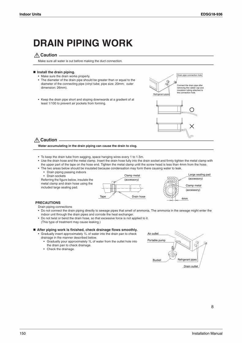
Indoor Units EDSG18-936
8
DRAIN PIPING WORKCaution
Make sure all water is out before making the duct connection.
Install the drain piping.• Make sure the drain works properly.• The diameter of the drain pipe should be greater than or equal to the
diameter of the connecting pipe (vinyl tube; pipe size: 20mm; outer dimension: 26mm).
• Keep the drain pipe short and sloping downwards at a gradient of at least 1/100 to prevent air pockets from forming.
CautionWater accumulating in the drain piping can cause the drain to clog.
• To keep the drain tube from sagging, space hanging wires every 1 to 1.5m.• Use the drain hose and the metal clamp. Insert the drain hose fully into the drain socket and firmly tighten the metal clamp with
the upper part of the tape on the hose end. Tighten the metal clamp until the screw head is less than 4mm from the hose.• The two areas below should be insulated because condensation may form there causing water to leak.
• Drain piping passing indoors• Drain sockets
Referring the figure below, insulate the metal clamp and drain hose using the included large sealing pad.
PRECAUTIONS Drain piping connections• Do not connect the drain piping directly to sewage pipes that smell of ammonia. The ammonia in the sewage might enter the
indoor unit through the drain pipes and corrode the heat exchanger.• Do not twist or bend the drain hose, so that excessive force is not applied to it.
(This type of treatment may cause leaking.)
After piping work is finished, check drainage flows smoothly.• Gradually insert approximately 1L of water into the drain pan to check
drainage in the manner described below.• Gradually pour approximately 1L of water from the outlet hole into
the drain pan to check drainage.• Check the drainage.
Drain pipe connection hole
Refrigerant pipes
Connect the drain pipe after removing the rubber cap and insulation tubing attached to the connection hole.
4mm
Large sealing pad
Clamp metal
(accessory)
(accessory)Clamp metal
Drain hoseTape
(accessory)
Portable pump
Refrigerant pipesBucket
Air outlet
Drain outlet
150 Installation Manual

EDSG18-936 Indoor Units
3
9
INSTALLING THE DUCTConnect the duct supplied in the field.Air inlet side
• Attach the duct and intake-side flange (field supply).• Connect the flange to the main unit with accessory screws (in 16, 20 or 24 positions).• Wrap the intake-side flange and duct connection area with aluminum tape or something similar to prevent air escaping.
CautionWhen attaching a duct to the intake side, be sure also to attach an air filter inside the air passage on the intake side. (Use an air filter whose dust collecting efficiency is at least 50% in a gravimetric technique.)
Outlet side• Connect the duct according to the inside of the outlet-side flange.• Wrap the outlet-side flange and the duct connection area with aluminum tape or something similar to prevent air escaping.
Caution• Be sure to insulate the duct to prevent condensation from forming. (Material: glass wool or polyethylene foam, 25mm thick)• Use electric insulation between the duct and the wall when using metal ducts to pass metal laths of the net or fence shape or
metal plating into wooden buildings.
Main unit
Air inlet side Outlet side
Connection screw(accessory)
(Field supply)
(Field supply)
(Field supply)
(Field supply)
Flange
Flange
Aluminum tape
Aluminum tape
Insulation material
Installation Manual 151

Indoor Units EDSG18-936
10
WIRINGSee the installation manual supplied with the outdoor unit.
HOW TO CONNECT WIRINGS. • Wire only after removing the control box lid as shown in the Fig.
Caution• When clamping the wiring, use the included clamping material as shown in the Fig. to prevent outside pressure being exerted
on the wiring connections and clamp firmly.• When doing the wiring, make sure the wiring is neat and does not cause the control box lid to stick up, then close the cover
firmly. When attaching the control box lid, make sure you do not pinch any wires.• Outside the machine, separate the weak wiring (remote controller wiring) and strong wiring (earth wire and power supply wiring) at least
50mm so that they do not pass through the same place together. Proximity may cause electrical interference, malfunctions, and breakage.
[ PRECAUTION ] • See also the “Electrical Wiring Diagram Nameplate” when wiring the unit for electrical power.
[ Connecting electrical wiring ]
• Power supply wiring and Earth wireRemove the control box lid.Next, pull the wires into the unit through the wiring through hole and connect to the power wiring terminal block (4P).Be sure to put the part of the sheathed vinyl into the control box.
WarningDo not use tapped wires, stand wires, extensioncords, or starbust connections, as they may cause overheating, electrical shock, or fire.
Make sure to let a wire go through a wire penetration area. After wir ing, seal the wire and wire penetration area to prevent moisture and small creatures from the outside.
Wrap the strong and weak electric lines with the sealing material as shown in the figure below.(Otherwise, moisture or small creatures such as insects from the outside may cause short-circuit inside the control box.)Attach securely so that there are no gaps.
Insideunit
Outsideunit
[How to adhere it]
Wire
(accessory)Sealing material Wiring
through hole
Wiring
Clasp
(Control box side)
(Power supply side)
Clamp (for fixing in place) (accessory)
∗Remote controller wiring
Power supply wiringEarth wire
Control box lid
Wiring Diagram(Rear)
Terminal block (4P)
Wiring through hole
Power supply wiringEarth wire
Power supply wiringEarth wire
Clamp (for fixing in place)
(accessory)
Indoor PCboard(ASSY)
123
When wire length exceeds 10m, use 2.0mm wires.
1.6mm or 2.0mm
To outdoor unit
Indoor unit
H05VV
152 Installation Manual

EDSG18-936 Indoor Units
3
11
TRIAL OPERATION AND TESTING(1) Measure the supply voltage and make sure that it falls in the specified range.(2) Trial operation should be carried out in either cooling or heating mode.
For Heat pump.In cooling mode, select the lowest programmable temperature; in heating mode, select the highest programmable temperature.
• Trial operation may be disabled in either mode depending on the room temperature.• After trial operation is complete, set the temperature to a normal level (26˚C to 28˚C in cooling mode, 20˚C to 24˚C in
heating mode).• For protection, the system disables restart operation for 3 minutes after it is turned off.
For Cooling only.Select the lowest programmable temperature.
• Trial operation in cooling mode may be disabled depending on the room temperature.Use the remote control for trial operation as described below.
• After trial operation is complete, set the temperature to a normal level (26°C to 28°C).• For protection, the unit disables restart operation for 3 minutes after it is turned off.
(3) Carry out the test operation in accordance with the Operation Manual to ensure that all functions and parts, are working properly.* The air conditioner requires a small amount of power in its standby mode. If the system is not to be used for some time after
installation, shut off the circuit breaker to eliminate unnecessary power consumption.* If the circuit breaker trips to shut off the power to the air conditioner, the system will restore the original operation mode when
the circuit breaker is turned on again.
Trial operation and testing
(1) Press ON/OFF button to turn on the system.(2) Simultaneously press center of TEMP button and MODE button.(3) Press MODE button twice.
(“ ” will appear on the display to indicate that Trial Operation mode is selected.)(4) Trial run mode terminates in approx. 30 minutes and switches into normal mode. To quit a trial operation, press
ON/OFF button.
Trial operation from remote controller
Test items
CheckSymptom
(diagnostic display on RC)Test items
Indoor and outdoor units are installed properly on solid bases.No refrigerant gas leaks.
Refrigerant gas and liquid pipes and indoor drain hose extension are thermally insulated.Draining line is properly installed.System is properly earthed.The specified wires are used for interconnecting wire connections.
Indoor or outdoor unit’s air inlet or discharge has clear path of air.Shut-off valves are opened.Indoor unit properly receives remote controller commands.
Fall, vibration, noiseIncomplete cooling/heating functionWater leakage
Water leakageElectrical leakageInoperative or burn damage
Incomplete cooling/heating functionInoperative
3P132003-3N
Installation Manual 153

Indoor Units EDSG18-936
3.7 Ceiling Mounted Cassette Type FFQ25/35/50/60B
English 1
CONTENTS1. SAFETY PRECAUTIONS .......................................................................................... 12. BEFORE INSTALLATION........................................................................................... 23. SELECTING INSTALLATION SITE ............................................................................ 54. PREPARATIONS BEFORE INSTALLATION.............................................................. 65. INDOOR UNIT INSTALLATION.................................................................................. 76. REFRIGERANT PIPING WORK ................................................................................. 97. DRAIN PIPING WORK.............................................................................................. 118. WIRING EXAMPLE ................................................................................................... 149. ELECTRIC WIRING WORK ...................................................................................... 15
10. INSTALLATION OF THE DECORATION PANEL..................................................... 1711. FIELD SETTINGS ..................................................................................................... 1812. TEST OPERATION ................................................................................................... 19
1. SAFETY PRECAUTIONSPlease read these “SAFETY PRECAUTIONS” carefully before installing air conditioning equipment and be sure to install it correctly.After completing installation, conduct a trial operation to check for faults and explain to the customer how to operate the air conditioner and take care of it with the aid of the operation manual. Ask the customer to store the installation manual along with the operation manual for future reference.This air conditioner comes under the term “appliances not accessible to the general public”.
Meaning of WARNING and CAUTION notices.
WARNING ........Failure to follow these instructions properly may result in personal injury or loss of life.
CAUTION .........Failure to observe these instructions properly may result in property damage or per-sonal injury, which may be serious depending on the circumstances.
WARNING• Ask your dealer or qualified personnel to carry out installation work.
Do not attempt to install the air conditioner yourself. Improper installation may result in water leakage, electric shocks or fire.
• Install the air conditioner in accordance with the instructions in this installation manual.Improper installation may result in water leakage, electric shocks or fire.
• Be sure to use only the specified accessories and parts for installation work.Failure to use the specified parts may result in the unit falling, water leakage, electric shocks or fire.
• Install the air conditioner on a foundation strong enough to withstand the weight of the unit.A foundation of insufficient strength may result in the equipment falling and causing injury.
• Carry out the specified installation work after taking into account strong winds, typhoons or earthquakes.Failure to do so during installation work may result in the unit falling and causing accidents.
• Make sure that a separate power supply circuit is provided for this unit and that all electrical work is carried out by qualified personnel according to local laws and regulations and this installation manual.An insufficient power supply capacity or improper electrical construction may lead to electric shocks or fire.
• Make sure that all wiring is secured, the specified wires are used, and that there is no strain on the termi-nal connections or wires.Improper connections or securing of wires may result in abnormal heat build-up or fire.
FFQ25BV1B
SPLIT SYSTEM Air Conditioners Installation manualFFQ35BV1BFFQ50BV1BFFQ60BV1B
154 Installation Manual

EDSG18-936 Indoor Units
3
2 English
• When wiring the power supply and connecting the wiring between the indoor and outdoor units, position the wires so that the control box lid can be securely fastened.Improper positioning of the control box lid may result in electric shocks, fire or overheating terminals.
• If refrigerant gas leaks during installation, ventilate the area immediately.Toxic gas may be produced if the refrigerant comes into contact with fire.
• After completing installation, check for refrigerant gas leakage.Toxic gas may be produced if the refrigerant gas leaks into the room and comes into contact with a source of fire, such as a fan heater, stove or cooker.
• Be sure to switch off the unit before touching any electrical parts.• Be sure to earth the air conditioner.
Do not earth the unit to a utility pipe, lightning conductor or telephone earth lead.Imperfect earthing may result in electric shocks or fire.A high surge current from lightning or other sources may cause damage to the air conditioner.
• Be sure to install an earth leakage breaker.Failure to install an earth leakage breaker may result in electric shocks or fire.
CAUTION• While following the instructions in this installation manual, install drain piping to ensure proper drainage and
insulate piping to prevent condensation.Improper drain piping may result in indoor water leakage and property damage.
• Install the indoor and outdoor units, power cord and connecting wires at least 1 meter away from televi-sions or radios to prevent picture interference and noise.(Depending on the incoming signal strength, a distance of 1 meter may not be sufficient to eliminate noise.)
• Remote controller (wireless kit) transmitting distance can be shorter than expected in rooms with elec-tronic fluorescent lamps (inverter or rapid start types).Install the indoor unit as far away from fluorescent lamps as possible.
• Do not install the air conditioner in the following locations:1. Where there is a high concentration of mineral oil spray or vapour (e.g. a kitchen).
Plastic parts will deteriorate, parts may fall off and water leakage could result.2. Where corrosive gas, such as sulphurous acid gas, is produced.
Corroding of copper pipes or soldered parts may result in refrigerant leakage.3. Near machinery emitting electromagnetic radiation.
Electromagnetic radiation may disturb the operation of the control system and result in a malfunction of the unit.
4. Where flammable gas may leak, where there is carbon fibre or ignitable dust suspensions in the air, or where volatile flammables such as paint thinner or gasoline are handled.Operating the unit in such conditions may result in fire.
• The air conditioner is not intended for use in a potentially explosive atmosphere.
2. BEFORE INSTALLATIONDo not exert pressure on the resin parts when opening the unit or when moving it after openingBe sure to check the type of R410A refrigerant to be used before doing any work. (Using an incorrect refrigerant will prevent normal operation of the unit.)• When opening the unit or moving it after opening, be sure to lift it by holding on to the lifting lugs without
exerting any pressure on other parts, especially, drain piping, and other resin parts.• Decide upon a line of transport.• Leave the unit inside its packaging while moving, until reaching the installation site. Use a sling of soft
material, where unpacking is unavoidable or protective plates together with a rope when lifting, to avoid damage or scratches to the unit.
• Especially, do not unfasten packing case(top) guarding the control box until suspending the unit.• Refer to the installation manual of the outdoor unit for items not described in this manual.• Do not dispose of any parts necessary for installation until the installation is complete.
Installation Manual 155

Indoor Units EDSG18-936
English 3
2-1 PRECAUTIONS• Be sure to read this manual before installing the indoor unit.• When selecting installation site, refer to the paper pattern.• This unit is suitable for installation in a household, commercial and light industrial environment.• Do not install or operate the unit in rooms mentioned below.
• Laden with mineral oil, or filled with oil vapor or spray like in kitchens. (Plastic parts may deteriorate.)• Where corrosive gas like sulfurous gas exists. (Copper tubing and brazed spots may corrode.)• Where volatile flammable gas like thinner or gasoline is used.• Where machines can generate electromagnetic waves. (Control system may malfunction.)• Where the air contains high levels of salt such as that near the ocean and where voltage fluctuates
greatly such as that in factories. Also in vehicles or vessels.
2-2 ACCESSORIES
Check the following accessories are included with your unit.
2-3 OPTIONAL ACCESSORIES• The optional decoration panel and remote controller are required for this indoor unit.(Refer to Table 1, 2)
Table 1
• These are two types of remote controllers: wired and wireless. Select a remote controller from Table 2 according to customer request and install in an appropriate place.
Table 2
NOTE• If you wish to use a remote controller that is not listed in “Table 2” on page 3, select a suitable remote con-
troller after consulting catalogs and technical materials .
Unit model Optional decoration panel
FFQ25·35·50·60BV1BBYFQ60BW1
Color : White
Remote controller type Cooling only type Heat Pump type
Wired type BRC1C61
Wireless type BRC7E531W BRC7E530W
Name (1)Drain hose (2)Metal clamp (4)Clamp(3)Washer for hanger bracket
(5)Paper pattern for installation
Quantity
Shape
Name
Quantity
Shape
Insulation for fitting(12)Sealing material
Sealing pad
1 pc. 1 pc.1 pc. 8 pcs. 6 pcs.(Big)
1 pc.(Small)
Also used as packing material
1 each. 1 each.
For paper patternfor installation
(6)Screws (M5)
(7)Washer fixing plate
4 pcs. 4 pcs. 2 pcs.
(Other)
Operation manual
Installationmanual
(8)For gas pipe
(9)For liquid pipe
(10)Large
(11)Small
156 Installation Manual

EDSG18-936 Indoor Units
3
4 English
FOR THE FOLLOWING ITEMS, TAKE SPECIAL CARE DURING CONSTRUCTION AND CHECK AFTER INSTALLATION IS FINISHED.
a. Items to be checked after completion of work
b. Items to be checked at time of deliveryAlso review the “SAFETY PRECAUTIONS”
c. Points for explanation about operations
2-4 NOTE TO THE INSTALLERBe sure to instruct customers how to properly operate the unit (especially cleaning filters, operating differ-ent functions, and adjusting the temperature) by having them carry out operations themselves while look-ing at the manual.
Items to be checked If not properly done, what is likely to occur Check
Are the indoor and outdoor unit fixed firmly? The units may drop, vibrate or make noise.
Is the outdoor unit fully installed?The unit may malfunction or the compo-nents burn out.
Is the gas leak test finished? It may result in insufficient cooling.
Is the unit fully insulated? Condensate water may drip.
Does drainage flow smoothly? Condensate water may drip.
Does the power supply voltage correspond to that shown on the name plate?
The unit may malfunction or the compo-nents burn out.
Are wiring and piping correct?The unit may malfunction or the compo-nents burn out.
Is the unit safely grounded? Dangerous at electric leakage.
Is wiring size according to specifications?The unit may malfunction or the compo-nents burn out.
Is something blocking the air outlet or inlet of either the indoor or outdoor units?
It may result in insufficient cooling.
Are refrigerant piping length and additional refrigerant charge noted down?
The refrigerant charge in the system is not clear.
Items to be checked Check
Are the control box lid, air filter, suction grille attached?
Did you explain about operations while showing the instruction manual to your customer?
Did you hand the instruction manual over to your customer?
The items with WARNING and CAUTION marks in the instruction manual are the items per-taining to possibilities for bodily injury and material damage in addition to the general usage ofthe product. Accordingly, it is necessary that you make a full explanation about the described contents and also ask your customers to read the instruction manual.
Installation Manual 157

Indoor Units EDSG18-936
English 5
3. SELECTING INSTALLATION SITE⟨Hold the unit by the 4 lifting lugs when opening the box and moving it, and do not exert pressure on to any other part piping (refrigerant, drain, etc.) or plastic parts. If the temperature or humidity inside the ceiling might rise above 30˚C or RH 80%, respectively, use the high-humidity kit (sold separately) or add extra insulation to the main unit body. Use glass wool or polyethylene foam as insulation and make sure it is at least 10mm thick and fits inside the ceiling opening.⟩The direction this product blows can be selected. However, a separately sold shut-off material kit is needed in order to make the unit blow in two, three, or four (corner shut-off) directions.(1) Select an installation location with the customer’s approval which matches the following condi-
tions.• A location from which cool (warm) air will reach the whole room.• A location with no objects blocking the air passage.• A location where drainage can be done with no problem.• A location strong enough to support the weight of the indoor unit. • Locations where the wall is not significantly tilted.• A location which leaves enough room for installation and service work. • A location where there is no risk of flammable gas leaking. • A location where the length of the indoor-outdoor piping is no longer than the tolerated length (see the
installation manual that came with the outdoor unit for details).
NOTE• Leave 200 mm or more space where marked with the *, on sides where the air outlet is closed.
CAUTION• Install the indoor and outdoor units, power cord and connecting wires at least 1 meter away from televi-
sions or radios in order to prevent image interference or noise.(Depending on the radio waves, a distance of 1 meter may not be sufficient enough to eliminate the noise.)
(2) Air flow directionThe air direction shown is an example.Select the appropriate number of directions according to the shape of the room and the location of the unit. (Field settings have to be made using the remote controller and the outlet vents have to be shut off if two, three, or four (corner shut-off) directions are selected. See the shut-off materials (sold separately) installation manual for details.)
Model H
FFQ25·35·50·60 285 (Confirm the space of 295 or more)
H
1500
>2500
> 1500>
* 1500>
*
1500>
*1500
>*
1500>
*1500>
*
Airoutlet
For
inst
alla
tion
in h
igh
plac
es
Airinlet
Airoutlet
Fig. 1
Fig. 2
[Space required for installation] (mm)
158 Installation Manual

EDSG18-936 Indoor Units
3
6 English
(3) Use suspension bolts for installation. Check whether the ceiling is strong enough to support the weight of the unit or not. If there is a risk, reinforce the ceiling before installing the unit.(Installation pitch is maked on the paper pattern for installation. Refer to it to check for points requiring reinforcing.)
4. PREPARATIONS BEFORE INSTALLATION(1) Relation of ceiling opening to unit and suspension bolt position.
NOTE• Installation is possible with a ceiling dimension of 660 mm (marked with *). However, to achieve a ceiling-
panel overlapping dimension of 20 mm, the spacing between the ceiling and the unit should be 45 mm or less. If the spacing between ceiling and the unit is over 45 mm, attach ceiling material to part or recover the ceiling.
(2) Make the ceiling opening needed for installation where applicable. (For existing ceilings)• Refer to the paper pattern for installation (5) for ceiling opening dimensions.• Create the ceiling opening required for installation. From the side of the opening to the casing out-
let,implement the refrigerant and drain piping and wiring for remote controller (unnecessary for wire-less type) and wiring between units. Refer to each PIPING or WIRING section.
• After making an opening in the ceiling, it may be necessary to reinforce ceiling beams to keep the ceil-ing level and to prevent it from vibrating. Consult the builder for details.
Piping Piping Piping
Air outlet in4 directions
Air outlet in3 directions
Air outlet in2 directions
[Air flow direction] (Example)70
0 (D
ecor
atio
n pa
nel)
585-
660
(Cei
ling
open
ing)
575
(indo
or u
nit)
533
(Sus
pens
ion b
olt p
itch)
700 (Decoration panel)585-660 (Ceiling opening)
575 (indoor unit)533 (Suspension bolt pitch)
Refrigerantpiping
Suspensionbolt ( 4)
Falseceiling
Hangerbracket
View as seen from A
(Ceiling opening dimension)
(mm)(Ceiling-panel overlapping dimension)
585 – *660
(180
)
20
AFig. 3 Fig. 4
≤ 20≤
Ceiling material<45 <45
Fig. 5
Falseceiling
Falseceiling
(mm)
Installation Manual 159

Indoor Units EDSG18-936
English 7
(3) Install the suspension bolts.(Use either a M8 ~ M10 size bolt)Use a hole-in anchor for existing ceilings, anda sunken insert, sunken anchor or other fieldsupplied parts for new ceilings to reinforcethe ceiling to bear the weight of the unit.Adjust clearance (50 – 100 mm) from theceiling before proceeding further.
NOTE• All the above parts are field supplied.
5. INDOOR UNIT INSTALLATIONInstalling optional accessories (except for the decoration panel) before installing the indoor unit is easier. However, for existing ceilings, install fresh air inlet component kit and branch duct before installing the unit.As for the parts to be used for installation work, be sure to use the provided accessories and specified parts designated by our company.
(1) For new ceilings(1-1) Install the indoor unit temporarily.
• Attach the hanger bracket to the suspension bolt. Be sure to fix it securely by using a nut and washer (3) from the upper and lower sides of the hanger bracket.The washer fixing plate (7) will prevent the washer from falling.
(1-2) Refer to the paper pattern for installation (5) for ceilling opening dimension. Consult the builder or carpenter for details.
• The center of the ceiling opening is indicated on the paper pattern for installation.The center of the unit is indicated on the paper pattern for installation.
• Fix the paper pattern to the unit with screws (6) (×4).• Ceiling height is shown on the side of the paper pattern for installation (5). Adjust the height of the
unit according to this indication.• Please perform one of the following, as the shape of the paper pattern for installation differs
according to the model.
Fig. 7 Fig. 8
<installation example>
Ceiling slabAnchorLong nut or turn-buckleSuspension bolt
False ceiling
Fig. 6
(mm)
Nut (Field supplied)
Washer (3) (accessory)
Hanger bracket
Tighten(double nuts)
[Securing the hanger bracket]
Insert
(accessory)Washer fixing plate (7)
[Securing the washer]
Paper pattern for installation (5)
Screws (6) (accessory)
Screws (6) (accessory) [Installation of paper pattern for installation]
Fig. 9
(accessory)
160 Installation Manual

EDSG18-936 Indoor Units
3
8 English
<Ceiling work>(1-3) Adjust the unit to the right position for installation. (Refer to 4.PREPARATIONS BEFORE INSTALLATION-(1).)(1-4) Check the unit is horizontally level.
• The indoor unit is equipped with a built-in drain pump and float switch. Verify that it is level by using a water level or a waterfilled vinyl tube.
CAUTIONIf the unit is tilted against condensate flow, the float switch may malfunction and cause water to drip.
(1-5) Remove the washer fixing plate (7) used for pre- venting the washer from falling and tighten the upper nut.(1-6) Remove the paper pattern for installation (5).
(2) For existing ceilings(2-1) Install the indoor unit temporarily.
• Attach the hanger bracket to the suspension bolt. Be sure to fix it securely by using a nut and washer (3) from the upper and lower sides of hanger bracket. The washer fixing plate (7) will pre-vent the washer from falling.
(2-2) Adjust the height and position of the unit. (Refer to 4.PREPARATIONS BEFORE INSTALLATION-(1).)(2-3) Perform steps (1-4), (1-5) in (1) For new ceilings.
Fig. 11 Fig. 12
Water level Vinyl tube
[Maintaining horizontality]
Fig. 10
Nut (Field supplied)
Washer (3) (accessory)
Hanger bracket
Tighten(double nuts)
[Securing the hanger bracket]
Insert
(accessory)Washer fixing plate (7)
[Securing the washer]
Installation Manual 161

Indoor Units EDSG18-936
English 9
6. REFRIGERANT PIPING WORK<For refrigerant piping of outdoor units, see the installation manual attached to the outdoor unit.><Execute heat insulation work completely on both sides of the gas piping and the liquid piping. Otherwise, a water leakage can result sometimes.>(When using a heat pump, the temperature of the gas piping can reach up to approximately 120˚C, so use insulation which is sufficiently resistant.)<Also, in cases where the temperature and humidity of the refrigerant piping sections might exceed 30˚C or RH80%, reinforce the refrigerant insulation. (20 mm or thicker) Condensation may form on the surface of the insulating material.><Before refrigerant piping work, check which type of refrigerant is used. Proper operation is not pos-sible if the types of refrigerant are not the same.>
CAUTION• Use a pipe cutter and flare suitable for the type of refrigerant.• Apply ester oil or ether oil around the flare portions before connectiong.• To prevent dust, moisture or other foreign matter from infiltrating the tube, either pinch the end
or cover it with tape.• Do not allow anything other than the designated refrigerant to get mixed into the refrigerant
circuit, such as air, etc. If any refrigerant gas leaks while working on the unit, ventilate the room thoroughly right away.
• The outdoor unit is charged with refrigerant. • Be sure to use both a spanner and torque wrench together, as
shown in the drawing, when connecting or disconnecting pipes to/from the unit. (Refer to Fig. 13)
• Refer to “ Table 3” for the dimensions of flare nut spaces.• When connecting the flare nut, coat the flare section (both inside and
outside) with ester oil or ether oil, rotate three or four times first, then screw in. (Refer to Fig. 14)
CAUTION
Over-tightening may damage the flare and cause a refrigerant leakage.
NOTE• Use the flare nut included with the unit main body.Table 3
• Refer to “Table 3” to determine the proper tightening torque.
Pipe size Tightening torqueFlare dimensions
A (mm)Flare
ø6.4(1/4") 14.2 - 17.2 N·m(144 - 175 kgf·cm) 8.7-9.1
ø9.5(3/8") 32.7 - 39.9 N·m(333 - 407 kgf·cm) 12.8-13.2
ø12.7(1/2") 49.5 - 60.3 N·m(505 - 615 kgf·cm) 16.2 - 16.6
Torque wrench
Flare nut
Piping union
Spanner
Fig. 13
Apply ester oil or ether oil only inside
Fig. 14
162 Installation Manual

EDSG18-936 Indoor Units
3
10 English
Not recommendable but in case of emergency You must use a torque wrench but if you are obliged to install the unit without a torque wrench, you may fol-low the installation method mentioned below.
After the work is finished, make sure to check that there is no gas leak.
When you keep on tightening the flare nut with a spanner, there is a point where the tightening torque sud-denly increases. From that position, further tighten the flare nut the angle shown below:
CAUTIONCAUTION TO BE TAKEN WHEN BRAZING REFRIGERANT PIPING“Do not use flux when brazing refrigerant piping. Therefore, use the phosphor copper brazing filler metal (BCuP-2: JIS Z 3264/B-Cu93P-710/795: ISO 3677) which does not require flux.”(Flux has extremely harmful influence on refrigerant piping systems. For instance, if the chlorine based flux is used, it will cause pipe corrosion or, in particular, if the flux contains fluorine, it will damage the refrigerant oil.)
• Before brazing local refrigerant piping, nitrogen gas shall be blown through the piping to expel air from the piping.If your brazing is done without nitrogen gas blowing, a large amount of oxide film develops inside the pip-ing, and could cause system malfunction.
• When brazing the refrigerant piping, only begin brazing after having carried out nitrogen substitution or while inserting nitrogen into the refrigerant piping. Once this is done, connect the indoor unit with a flared or a flanged connection.
• Nitrogen should be set to 0.02 MPa (0.2 kg/cm2) with a pressure-reducing valve if brazing while inserting nitrogen into the piping. (Refer to Fig.15)
• Make absolutely sure to execute heat insulation works on the pipe-connecting section after checking gas leakage by thoroughly studying the following figure and using the attached heat insulating materials for fit-ting (8) and (9). (Fasten both ends with the clamps (4).)
(Refer to Fig. 16)• Wrap the sealing pad (11) only around the insulation for the joints on the gas piping side. (Refer to Fig. 16)
Pipe size Further tightening angle Recommended arm length of tool
ø6.4 (1/4") 60 – 90 degrees Approx. 150mm
ø9.5 (3/8") 60 – 90 degrees Approx. 200mm
ø12.7 (1/2") 30 – 60 degrees Approx. 250mm
Nitrogen
Pressure-reducing valvehands valve
TapingRefrigerant piping
Part to be brazed
NitrogenFig. 15
Installation Manual 163

Indoor Units EDSG18-936
English 11
CAUTIONBe sure to insulate any field piping all the way to the piping connection inside the unit. Any exposed piping may cause condensation or burns if touched.
7. DRAIN PIPING WORK(1) Carry out the drain piping • Lay pipes so as to ensure that drainage can occur with problems.• Employ a pipe with either the same diameter or with the diameter larger (excluding the raising section)
than that of the connecting pipe (PVC pipe, nominal diameter 20 mm, outside diameter 26 mm).• keep the drain pipe short and sloping downwards at a gradient of at least 1/100 to prevent air pockets from
forming.• If the drain hose cannot be sufficiently set on a slope, refer to PRECAUTIONS FOR DRAIN RAISING PIP-
ING on page 12.• To keep the drain hose from sagging, space hanger bracket every 1 to 1.5 m.
CAUTIONWater pooling in the drainage piping can cause the drain to clog.
• Use the attached drain hose (1) and metal clamp (2).• Insert the drain hose into the drain socket up to the base, and tighten the clamp securely within the portion
of a gray tape of the hose-inserted tip. Tighten the clamp until the screw head is less than 4 mm from the hose.
• Make sure that heat insulation work is executed on the following 2 spots to prevent any possible water leakage due to dew condensation.• Indoor drain pipe• Drain socket
• Wrap the attached sealing pad (10) over the metal clamp (2) and drain hose to insulate.
Small sealing pad(accessory) (11)
(Wrap the piping unionwith the sealing pad.)
Insulation for fitting(accessory) (9)
Insulation for fitting (accessory) (8)(for gas pipe)
(for liquid pipe)
Gas pipingLiquid piping
Clamp (4)(Big 4)
Fig. 16
(accessory)
Hanger bracket
GOOD WRONG
Fig. 17 Fig. 18
WRONG
gradient or more1/100
164 Installation Manual
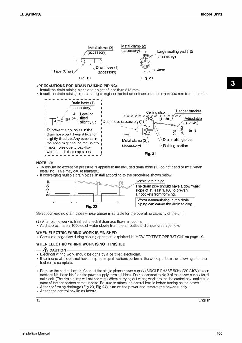
EDSG18-936 Indoor Units
3
12 English
<PRECAUTIONS FOR DRAIN RAISING PIPING>• Install the drain raising pipes at a height of less than 545 mm.• Install the drain raising pipes at a right angle to the indoor unit and no more than 300 mm from the unit.
NOTE• To ensure no excessive pressure is applied to the included drain hose (1), do not bend or twist when
installing. (This may cause leakage.)• If converging multiple drain pipes, install according to the procedure shown below.
Select converging drain pipes whose gauge is suitable for the operating capacity of the unit.
(2) After piping work is finished, check if drainage flows smoothly.• Add approximately 1000 cc of water slowly from the air outlet and check drainage flow.
WHEN ELECTRIC WIRING WORK IS FINISHED• Check drainage flow during cooling operation, explained in “HOW TO TEST OPERATION” on page 19.
WHEN ELECTRIC WIRING WORK IS NOT FINISHED
CAUTION• Electrical wiring work should be done by a certified electrician.• If someone who does not have the proper qualifications performs the work, perform the following after the
test run is complete.
• Remove the control box lid. Connect the single phase power supply (SINGLE PHASE 50Hz 220-240V) to con-nections No.1 and No.2 on the power supply terminal block. Do not connect to No.3 of the power supply termi-nal block. (The drain pump will not operate.) When carrying out wiring work around the control box, make sure none of the connectors come undone. Be sure to attach the control box lid before turning on the power.
• After confirming drainage (Fig.23, Fig.24), turn off the power and remove the power supply. • Attach the control box lid as before.
Metal clamp (2) Metal clamp (2)
Drain hose (1)Tape (Gray) 4mm
(accessory)(accessory)
(accessory)
(accessory)Large sealing pad (10)
Fig. 19 Fig. 20
Ceiling slab
300 1-1.5m
Hanger bracket
AdjustableDrain hose (accessory)(1) ( 545)
7
50
205
Drain raising pipe
Raising sectionMetal clamp (2)
Fig. 21
(accessory)
(mm)
Drain hose (1) (accessory)
To prevent air bubbles in the drain hose part, keep it level or slightly tilted up. Any bubbles in the hose might cause the unit to make noise due to backflow when the drain pump stops.
Level or tilted slightly up
0 –
545m
m
Fig. 22
Water accumulating in the drain piping can cause the drain to clog.
Central drain pipeThe drain pipe should have a downward slope of at least 1/100 to prevent air pockets from forming.
Installation Manual 165

Indoor Units EDSG18-936
English 13
CAUTIONDrain piping connectionsDo not connect the drain piping directly to sewage pipes that smell of ammonia. The ammonia in the sewage might enter the indoor unit through the drain pipes and corrode the heat exchanger.Keep in mind that it will become the cause of getting drain pipe blocked if water collects on drain pipe.
Drain sockets
(Check the drainage now.)
Service drain outlet (with rubber plug)(Use this outlet to drain water from the drain pan)Plastic container
for pouring
(Tube should be about 100 mm long.)
100
<Adding water through air outlet>
[Method of adding water]Fig. 23
(mm)
Drain pump location
1 2 3
Single phasepower supply
(50Hz 220-240V)
No.1 No.2No.3
Power supplyterminal block
Ground
Fig. 24
Control box lid
Remove thecontrol box lid(take off 2 screws)
166 Installation Manual

EDSG18-936 Indoor Units
3
14 English
8. WIRING EXAMPLEFor the wiring of outdoor units, refer to the installation manual attached to the outdoor units.Confirm the system type.• Pair type: 1 remote controller controls 1 indoor unit. (standard system) (Refer to Fig. 25)• Multi system: 1 through 4 indoor units connect to 1 outdoor unit. The indoor unit is controlled by remote
controller connected to each indoor unit. (Refer to Fig. 26)However, the group control is not expected.
• Group control: 1 remote controller controls up to 16 indoor units. (All indoor units operate according to the remote controller) (Refer to Fig. 27)
• 2 remote controllers control: 2 remote controllers control 1 indoor unit. (Refer to Fig. 28)
NOTE1. All transmission wiring except for the remote controller wires is polarized and must match the terminal
symbol.2. In case a shielding wire is to be used, connect a shielded portion with the of a remote controller ter-
minal board.(Also, connect the ground for the remote control to a grounded metal part.)3. For group control remote controller, choose the remote controller that suits the indoor unit which has the
most functions (as attached swing flap)4. When controlling the simultaneous operation system with 2 remote controllers, connect it to the master
unit. (wiring to the slave unit is unnecessary)
Pair type Multi system Main power supply
Main switch
1 2 3
1
P P
2 3
1
P1
2
P2
Fuse
Outdoor unit
Indoor unit
Group controlMain power supply
Main switch
1 2 3
1
P P
2 3
1
P1
2
P2
Fuse
Outdoor unit
Main power supply
Main switch
1 2 3
1
P P
2 3
1 2
Fuse
Outdoor unit
Main power supply
Main switch
1 2 3
1
P P
2 3
1 2
Fuse
Outdoor unit
Indoor unit Indoor unit Indoor unit
Fig. 25
Fig. 27 Fig. 28
Fig. 26
Remote controller 2(Optional accessories)
Remote controller 1(Optional accessories)
Remote controller(Optional accessories)
Remote controller(Optional accessories)
2 remote controllers controlMain power supply
Main switch
1 2 3
1
P P
2 3
1
P1
2
P2P1 P2
Fuse
Outdoor unit
Indoor unit
Main power supply
Main switch
1 2 3
1 2 3
P P1 2
P P1 2
1 2 3
1 2 3
P P1 2
P P1 2
1 2 3
1 2 3
P P1 2
P P1 2
Fuse
Outdoor unit
Indoor unit
Indoor unit
Indoor unit
Remote controller(Optional accessories)
Installation Manual 167

Indoor Units EDSG18-936
English 15
9. ELECTRIC WIRING WORK• All field supplied parts and materials and electric works must conform to local codes.• Use copper wire only.• For electric wiring work, refer to also “Wiring diagram label” attached to the Control box lid.• For remote controller wiring details, refer to the installation manual attached to the remote controller.• All wiring must be performed by an authorized electrician.• A circuit breaker capable of shutting down power supply to the entire system must be installed.• Refer to the installation manual attached to the outdoor unit for the size of power supply electric wire con-
nected to the outdoor unit, the capacity of the circuit breaker and switch, and wiring instructions.• Be sure to ground the air conditioner.• Do not connect the ground wire to gas and water pipes, lightning rods, or telephone ground wires.
• Gas pipes : might cause explosions or fire if gas leaks.• Water pipes : no grounding effect if hard vinyl piping is used.• Telephone ground wires or lightning rods : might cause abnormally high electric potential in the ground
during lighting storms.
• Specifications for field wireThe remote controller cord should be procured locally. Refer to the Table 4 when preparing one.
Table 4
*This will be the total extended length in the system when doing group control.
NOTE1. Shows only in case of protected pipes. Use H07RN-F in case of no protection.2. Asian market : Vinyl cord with sheath or cable (Insulated thickness : 1mm or more) For Australian regular : Shield wire (Insulated thickness : 1mm or more)
CAUTION• Arrange the wires and fix a lid firmly so that the lid does not float during wiring work.• Do not clamp remote controller cords together with wiring between units together. Doing so may cause
malfunction.• Remote controller cords and wiring between units should be located at least 50 mm from other electric
wires. Not following this guideline may result in malfunction due to electrical noise.
Connection of wiring between units, ground wire and for the remote control cord (Refer to Fig. 29)• Wiring between units and ground wire
Remove the control box lid and connect wires of matching number to the power supply terminal block(4P)inside. And connect the ground wire to the terminal block. In doing this, pull the wires inside through the hole and fix the wires securely with the included clamp (4).
• Give enough slack to the wires between the clamp (4) and power supply terminal block. (Use Fig. 30 as a guide and allow at least 80mm for removing the sheath.)
• Remove the control box lid and pull the wires inside through the hole and connect to the terminal block for remote controller (6P). (no polarity) Securely fix the remote controller cord with the included clamp (4).
• Give enough slack to the wires between the clamp (4) and the terminal block for the remote controller.• After connection, attach sealing material (12)• Be sure to attach it to prevent the infiltration of water as well as any insects and other small creatures from
the outside. Otherwise a short circuit may occur inside the control box.
Wire Size(mm2) Length(m)
Wiring between units H05VV-U4G(NOTE 1) 2.5 –
Remote controller cord Vinyl cord with sheath or cable (2 wire) (NOTE 2) 0.75-1.25 Max.500 *
Wiring to ground terminal Ground wire conform to local codes 2.0 –
168 Installation Manual
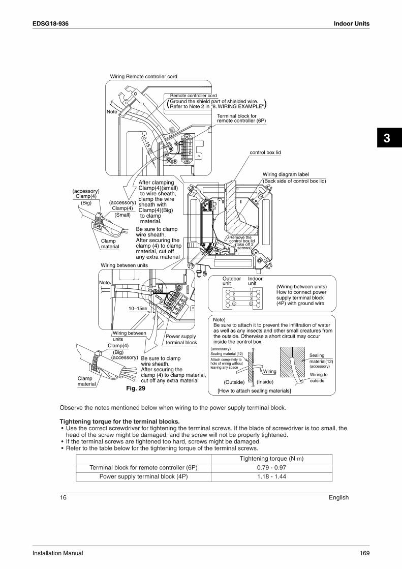
EDSG18-936 Indoor Units
3
16 English
Observe the notes mentioned below when wiring to the power supply terminal block.
Tightening torque for the terminal blocks.• Use the correct screwdriver for tightening the terminal screws. If the blade of screwdriver is too small, the
head of the screw might be damaged, and the screw will not be properly tightened.• If the terminal screws are tightened too hard, screws might be damaged.• Refer to the table below for the tightening torque of the terminal screws.
Tightening torque (N·m)
Terminal block for remote controller (6P) 0.79 - 0.97
Power supply terminal block (4P) 1.18 - 1.44
Wiring betweenunits
Power supplyterminal block
Ground the shield part of shielded wire.Refer to Note 2 in "8. WIRING EXAMPLE" ( ) Remote controller cord
Terminal block for remote controller (6P)
control box lid
Wiring Remote controller cord
Wiring between units
Wiring diagram label(Back side of control box lid)
Remove thecontrol box lid (take off 2 screws)
NoteOutdoorunit
Indoorunit
(Wiring between units)How to connect powersupply terminal block(4P) with ground wire
Fig. 29
Be sure to attach it to prevent the infiltration of water as well as any insects and other small creatures from the outside. Otherwise a short circuit may occur inside the control box.
Sealing material (12)
Attach completely tohole of wiring withoutleaving any space
[How to attach sealing materials]
Wiring tooutside(Outside)
10~15mm
Wiring
(Inside)
Sealingmaterial(12)
Note)
10~15 mm
Be sure to clamp wire sheath. After securing the clamp (4) to clamp material,cut off any extra material
Be sure to clamp wire sheath. After securing the clamp (4) to clamp material, cut off any extra material
After clamping Clamp(4)(small) to wire sheath,clamp the wiresheath with Clamp(4)(Big) to clamp material.
Clamp(4)(Small)
Clampmaterial
Note
Clampmaterial
Clamp(4)(Big)
Clamp(4)(Big)
(accessory)
(accessory)
(accessory)
(accessory)
(accessory)
Installation Manual 169

Indoor Units EDSG18-936
English 17
Precautions to be taken for power supply wiringUse a round crimp-style terminal for connection to the power supply terminal block. In case it cannot be used due to unavoidable reasons, be sure to observe the following instructions. Be sure to peel off the sheath of wiring between units more than 80 mm.(Refer to Fig. 30)• In wiring, make certain that prescribed wires are used, carry out complete connections, and fix the wires
so that external forces are not applied to the terminals.
When none are available, follow the instructions below.• Do not connect wires of different gauge to the same power supply terminal.
(Looseness in the connection may cause overheating.)
CAUTION• When clamping wiring, use the included clamping material to prevent outside pressure being exerted on the
wiring connections and clamp firmly. When doing the wiring, make sure the wiring is neat and does not cause the control box lid to stick up, then close the cover firmly.
• When attaching the control box lid, make sure you do not pinch any wires.• After all the wiring connections are done, fill in any gaps in the through holes with putty or insulation (pro-
cured locally) to prevent small animals and insects from entering the unit from outside. (If any do get in, they could cause short circuits in the control box.)
• Outside the machine, separate the weak wiring (remote controller cord) and strong wiring (interunit, ground, and other power wiring) at least 50 mm so that they do not pass through the same place together. Proximity may cause electrical interference, malfunctions, and breakage.
10. INSTALLATION OF THE DECORATION PANELCaution:With a wireless remote controller, field setting and test operation cannot be performed without attaching the decoration panel.<Read “12. TEST OPERATION” before making a test run without attaching the decorated panels.>Refer to the installation manual attached to the decoration panel.After installing the decoration panel, ensure that there is no space between the unit body and decoration panel.
Round crimp-style terminal
Attach insulation sleeve
Wiring between units
80mm or
mor
e
Fig. 30
Connect wires of the same gauge to both side.
Do not connect wires of the same gauge to one side.
Do not connect wires of different gauges.
170 Installation Manual
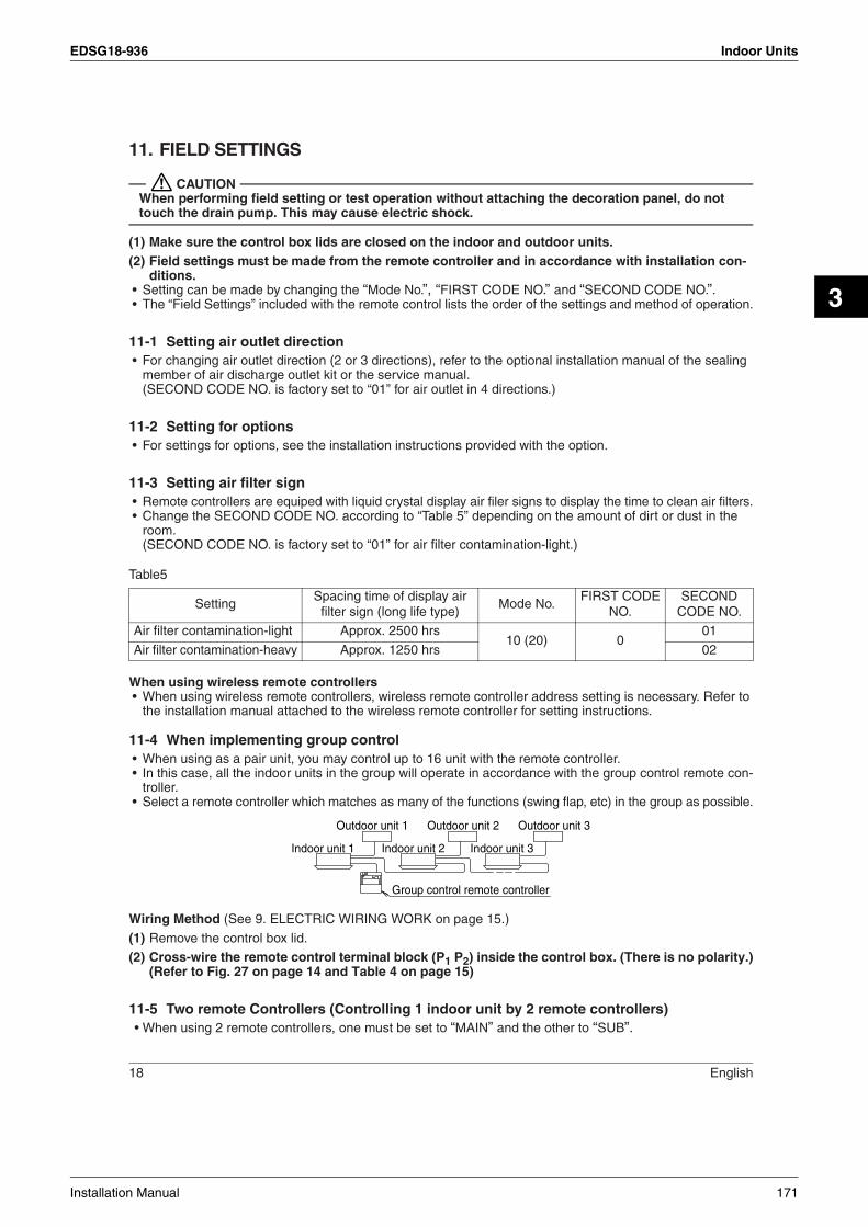
EDSG18-936 Indoor Units
3
18 English
11. FIELD SETTINGS
CAUTIONWhen performing field setting or test operation without attaching the decoration panel, do not touch the drain pump. This may cause electric shock.
(1) Make sure the control box lids are closed on the indoor and outdoor units.(2) Field settings must be made from the remote controller and in accordance with installation con-
ditions.• Setting can be made by changing the “Mode No.”, “FIRST CODE NO.” and “SECOND CODE NO.”.• The “Field Settings” included with the remote control lists the order of the settings and method of operation.
11-1 Setting air outlet direction• For changing air outlet direction (2 or 3 directions), refer to the optional installation manual of the sealing
member of air discharge outlet kit or the service manual. (SECOND CODE NO. is factory set to “01” for air outlet in 4 directions.)
11-2 Setting for options• For settings for options, see the installation instructions provided with the option.
11-3 Setting air filter sign• Remote controllers are equiped with liquid crystal display air filer signs to display the time to clean air filters.• Change the SECOND CODE NO. according to “Table 5” depending on the amount of dirt or dust in the
room.(SECOND CODE NO. is factory set to “01” for air filter contamination-light.)
Table5
When using wireless remote controllers• When using wireless remote controllers, wireless remote controller address setting is necessary. Refer to
the installation manual attached to the wireless remote controller for setting instructions.
11-4 When implementing group control• When using as a pair unit, you may control up to 16 unit with the remote controller.• In this case, all the indoor units in the group will operate in accordance with the group control remote con-
troller.• Select a remote controller which matches as many of the functions (swing flap, etc) in the group as possible.
Wiring Method (See 9. ELECTRIC WIRING WORK on page 15.)
(1) Remove the control box lid.
(2) Cross-wire the remote control terminal block (P1 P2) inside the control box. (There is no polarity.)(Refer to Fig. 27 on page 14 and Table 4 on page 15)
11-5 Two remote Controllers (Controlling 1 indoor unit by 2 remote controllers)When u• sing 2 remote controllers, one must be set to “MAIN” and the other to “SUB”.
SettingSpacing time of display air
filter sign (long life type)Mode No.
FIRST CODENO.
SECONDCODE NO.
Air filter contamination-light Approx. 2500 hrs10 (20) 0
01
Air filter contamination-heavy Approx. 1250 hrs 02
Outdoor unit 1
Indoor unit 1
Group control remote controller
Indoor unit 2 Indoor unit 3
Outdoor unit 2 Outdoor unit 3
Installation Manual 171

Indoor Units EDSG18-936
English 19
MAIN/SUB CHANGEOVER(1) Insert a screwdriver into the recess between the upper and lower part of remote controller and, work-
ing from the 2 positions, pry off the upper part. (The remote controller PC board is attached to the upper part of remote controller.) (Refer to Fig. 31)
(2) Turn the main/sub changeover switch on one of the two remote controller PC boards to “S”. (Leave the switch of the other remote controller set to “M”.) (Refer to Fig. 32)
Wiring Method (See 9. ELECTRIC WIRING WORK on page15. )
(3) Remove the control box lid.
(4) Add remote controller 2 to the remote control terminal block (P1, P2) in the control box.(There is no polarity.) (Refer to Fig. 28 on page 14 and Table 4 on page 15)
12. TEST OPERATION
CAUTIONWhen performing field setting or test operation without attaching the decoration panel, do not touch the drain pump. This may cause electric shock.
Refer to the section of FOR THE FOLLOWING ITEMS, TAKE SPECIAL CARE DURING CONSTRUC-TION AND CHECK AFTER INSTALLATION IS FINISHED on page 4.• After finishing the construction of refrigerant piping, drain piping, and electric wiring, conduct test opera-
tion accordingly to protect the unit.
12-1 HOW TO TEST OPERATION1. Open the gas side stop valve.2. Open the liquid side stop valve.3. Electrify for 6 hours.4. Set to cooling operation with the remote controller and start operation by pressing ON/OFF button ( ).5. Press INSPECTION/TEST OPERATION button ( ) 4 times (2 times for wireless remote controller) and operate at Test Operation mode for 3 minutes.6. Press AIR FLOW DIRECTION ADJUST button ( ) to make sure the unit is in operation.7. Press INSPECTION/TEST OPERATION button ( ) and operate normally.8. Confirm function of unit according to the operation manual.9. If the decoration panel has not been installed, turn off the power after the test operation.
PRECAUTIONS1. Refer to “12-2 HOW TO DIAGNOSE FOR MALFUNCTION” if the unit does not operate properly.2. After completing the test run, press the INSPECTION/TEST OPERATION button once to put the unit in inspection mode, and make sure the malfunction code is “00”. (=normal) If the code reads anything other than “00”, refer to 12-2 HOW TO DIAGNOSE FOR MALFUNCTION.
NOTE• If a malfunction is preventing operation, refer to the malfunction diagnoses below.
Fig. 31 Fig. 32
Upper part ofremote controller
Lower part ofremote controller
Insert the screwdriverhere and gently work off the upper part ofremote controller.
MS
MS
RemotecontrollerPC board
(Factory setting)
(Only one remote controller needs to be changed if factory settings have remained untouched.)
172 Installation Manual

EDSG18-936 Indoor Units
3
20 English
12-2 HOW TO DIAGNOSE FOR MALFUNCTION• If the air conditioner does not operate normally after installing the air conditioner, a malfunction shown in
the table below may happen.
*After turning on the power, the maximun is 90 seconds, although it will only display “88”. This is not a prob-lem, and it will be set for 90 seconds.
Diagnose with the display on the liquid crystal display remote controller.1. With the wired remote controller. (Note 1)
When the operation stops due to trouble, operation lamp flashes, and “ ” and the malfunction code are indicated on the liquid crystal display. In such a case, diagnose the fault contents by referring to the table on the malfunction code list in case of group control, the unit No. is displayed so that the indoor unit No. with the trouble can be recognized. (Note 2)
2. With the wireless remote controller.(Refer also to the operation manual attached to the wireless remote controller)When the operation stops due to trouble. the display on the indoor unit flashes. In such a case, diagnose the fault contents with the table on the Error code list looking for the error code which can be found by fol-lowing procedures. (NOTE 2)(1)Press the INSPECTION /TEST OPERATION button, “ ” is displayed and “ 0 ” flashes.(2)Press the PROGRAMMING TIME button and find the unit No. which stopped due to trouble.
Number of beeps 3 short beeps ............................. Perform all the following operations 1 short beep............................... Perform (3) and (6)1 long beep ................................ No trouble
(3)Press the OPERATION MODE SELECTOR button and upper figure of the error code flashes.(4)Continue pressing the PROGRAMMING TIME button unit it makes 2 short beeps and find the upper code.(5)Press the OPERATION MODE SELECTOR button and lower figure of the error code flashes.(6)Continue pressing the PROGRAMMING TIME button unit it makes a long beep and find the lower code.
• A long beep indicate the error code.NOTE1.In case wired remote controller. Press the INSPECTION/TEST OPERATION button on remote controller, “ ” starts flashing and changes the inspection mode.2.Keep down the ON/OFF button for 5 seconds or longer in the inspection mode and the above trouble history disappears, after the trouble code goes on and off twice, followed by the code “00”(normal). The display changes from the inspection mode to the normal mode.Caution:Check the items in “b. Items to be checked at time of delivery” on page 4 after a test operation.
12-3 Malfunction code list• For places where the Malfunction code is left blank, the “ ” indication is not displayed. Though the sys-
tem continues operating, be sure to inspect the system and make repairs as necessary.• Depending on the type of indoor or outdoor unit, the Malfunction code may or may not be displayed.
Remote control display Malfunction
No display
• Power supply trouble or Open phase connection• Wrong wiring between indoor and outdoor unit• Indoor PC board faulty• Power supply PCB assy faulty • Wrong remote control connection wiring• Remote control faulty• Fuse faulty
88* • Indoor PC board faulty • Wrong wiring between indoor and outdoor unit
88 flashing • Wrong wiring between indoor and outdoor unit
Code Malfunction/Remarks
A0 Safety device operates
A1 Indoor unit’s PC board faulty
A3 Drain water level abnormal
A6 Indoor fan motor overloaded, overcurrent or locked
AF Humidifier faulty
Installation Manual 173

Indoor Units EDSG18-936
English 21
AHAir cleaner faulty
Only the air cleaner does not function.
AJType set improper
Capacity data is wrongly preset. Or there is nothing programmed in the data hold IC.
C4 Sensor for heat exchanger temperature is fault
C9 Sensor for suction air temperature is fault
CC Humidity sensor abnormal
CJSensor for remote controller is fault
The remote controller thermistor does not function, but the system thermo run is possible.
E0 Action of safety device (outdoor unit)
E1 Outdoor unit’s PC board faulty
E3 High pressure abnormal (outdoor unit)
E4 Low pressure abnormal (outdoor unit)
E5 Compressor motor lock malfunction
E7Outdoor fan motor lock malfunctionOutdoor fan instantaneous overcurrent malfunction
E9 Electronic expansion valve faulty (outdoor unit)
F3 Discharge pipe temperature abnormal (outdoor unit)
H3 High pressure switch faulty (outdoor unit)
H4 Low pressure switch faulty (outdoor unit)
H7 Outdoor motor position signal malfunction
H9Outdoor air thermistor faulty (outdoor unit)
Equipment operation in response to errors will vary according to model.
JA Discharge pipe pressure sensor faulty
JC Suction pipe pressure sensor faulty
J1 Pressure sensor system error (batch) (outdoor unit)
J2 Power sensor system error (outdoor unit)
J3Discharge pipe thermistor faulty (outdoor unit)
Equipment operation in response to errors will vary according to model.
J5 Suction pipe thermistor faulty (outdoor unit)
J6Heat exchanger thermistor faulty (outdoor unit)
Equipment operation in response to errors will vary according to model.
J7Heat exchanger thermistor faulty (outdoor unit)
Equipment operation in response to errors will vary according to model.
J8 Liquid piping temperature sensor system error (outdoor unit)
J9 Intake temperature sensor error (outdoor unit)
L1 Inverter system error (outdoor unit)
L4Overheated heat-radiating fin (outdoor unit)
Inverter cooling defect.
L5Instantaneous overcurrent (outdoor unit)
Possible earth fault or short circuit in the compressor motor.
L8Electric thermal (outdoor unit)
Possible electrical overload in the compressor or cut line in the compressor motor.
L9Stall prevention (outdoor unit)
Compressor possibly locked.
LC Transmission malfunction between the outdoor control units’ inverters (outdoor unit)
174 Installation Manual
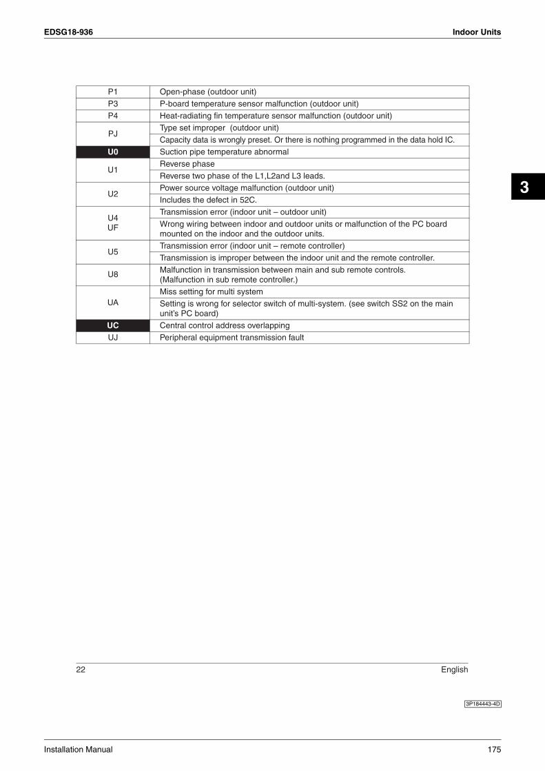
EDSG18-936 Indoor Units
3
22 English
P1 Open-phase (outdoor unit)
P3 P-board temperature sensor malfunction (outdoor unit)
P4 Heat-radiating fin temperature sensor malfunction (outdoor unit)
PJType set improper (outdoor unit)
Capacity data is wrongly preset. Or there is nothing programmed in the data hold IC.
U0 Suction pipe temperature abnormal
U1Reverse phase
Reverse two phase of the L1,L2and L3 leads.
U2Power source voltage malfunction (outdoor unit)
Includes the defect in 52C.
U4UF
Transmission error (indoor unit – outdoor unit)
Wrong wiring between indoor and outdoor units or malfunction of the PC board mounted on the indoor and the outdoor units.
U5Transmission error (indoor unit – remote controller)
Transmission is improper between the indoor unit and the remote controller.
U8 Malfunction in transmission between main and sub remote controls. (Malfunction in sub remote controller.)
UAMiss setting for multi system
Setting is wrong for selector switch of multi-system. (see switch SS2 on the main unit’s PC board)
UC Central control address overlapping
UJ Peripheral equipment transmission fault
3P184443-4D
Installation Manual 175

Indoor Units EDSG18-936
3.8 Ceiling Mounted Cassette Type FCQ35/50/60/71B
1. SAFETY CONSIDERATIONSPlease read these “SAFETY CONSIDERATIONS” carefully before installing air conditioning equipment and be sure to install it correctly. After completing the installation, make sure that the unit operates properly during the start-up operation. Please instruct the customer on how to operate the unit and keep it maintained.Also, inform customers that they should store this installation manual along with the operation manual for future reference.This air conditioner comes under the term “appliances not accesible to the general public”.
Meaning of warning and caution symbols.
WARNING .........Failure to observe a warning may result in death.
CAUTION ..........Failure to observe a caution may result in injury or damage to the equipment.
WARNING• Ask your dealer or qualified personnel to carry out installation work. Do not try to install the air conditioner
yourself.Improper installation may result in water leakage, electric shocks or fire.
• Perform installation work in accordance with this installation manual.Improper installation may result in water leakage, electric shocks or fire.
• Be sure to use only the specified accessories and parts for installation work.Failure to use the specified parts may result in water leakage, electric shocks, fire or the unit falling.
• Install the air conditioner on a foundation strong enough to withstand the weight of the unit.A foundation of insufficient strength may result in the equipment falling and causing injuries.
• Carry out the specified installation work after considering strong winds, typhoons or earthquakes.Improper installation work may result in the equipment falling and causing accidents.
• Make sure that a separate power supply circuit is provided for this unit and that all electrical work is carried out by qualified personnel according to local laws and regulations and this installation manual.An insufficient power supply capacity or improper electrical construction may lead to electric shocks or fire.
• Make sure that all wiring is secured, the specified wires and used, and no external forces act on the terminal connections or wires.Improper connections or installation may result in fire.
• When wiring the power supply and connecting the wiring between the indoor and outdoor units, position the wires so that the terminal box lids can be securely fastened.Improper positioning of the terminal box lids may result in electric shocks, fire or the terminals overheating.
• If the refrigerant gas leaks during installation, ventilate the area immediately.Toxic gas may be produced if the refrigerant gas comes into contact with fire.
• After completing the installation work, check that the refrigerant gas does not leak.Toxic gas may be produced if the refrigerant gas leaks into the room and comes into contact with a source of fire, such as a fan heater, stove or cooker.
• Before touching electrical parts, turn off the unit.
1
176 Installation Manual

EDSG18-936 Indoor Units
3
CAUTION• Ground the air conditioner.
Do not connect the ground wire to gas or water pipes, lightning conductor or a telephone ground wire.Incomplete grounding may result in electric shocks.
• Be sure to install an earth leakage breaker.Failure to install an earth leakage breaker may result in electric shocks.
• While following the instructions in this installation manual, install drain piping in order to ensure proper drainage and insulate piping in order to prevent condensate.Improper drain piping may result in water leakage and property damage.
• Install the indoor and outdoor units, power supply wiring and connecting wiring at least 1 meter away from televisions or radios in order to prevent image interference or noise.(Depending on the radio waves, a distance of 1 meter may not be sufficient enough to eliminate the noise.)
• Remote controller (wireless kit) transmitting distance can result shorter than expected in rooms with elec-tronic fluorescent lamps. (inverter or rapid start types) Install the indoor unit as far away from fluorescent lamps as possible.
• Do not install the air conditioner in the following locations:(a) where a mineral oil mist or an oil spray or vapor is produced, for example in a kitchen
Plastic parts may deteriorate and fall off or result in water leakage.(b) where corrosive gas, such as sulfurous acid gas, is produced
Corroding copper pipes or soldered parts may result in refrigerant leakage.(c) near machinery emitting electromagnetic waves
Electromagnetic waves may disturb the operation of the control system and result in a malfunction of the equipment.
(d) where flammable gases may leak, where there are carbon fiber or ignitable dust suspensions in the air, or where volatile flammables such as thinner or gasoline are handled.Operating the unit in such conditions may result in fire.
2. BEFORE INSTALLATION• Do not exert pressure on the resin parts when opening the unit or when moving it after opening.• Be sure to check the type of refrigerant to be used before installing the unit. (Using an incorrect refrigerant
will prevent normal operation of the unit.)• The accessories needed for installation must be retained in your custody until the installation work is com-
pleted. Do not discard them!• Decide upon a line of transport.• Leave the unit inside its packaging while moving, until reaching the installation site. Where unpacking is
unavoidable, use a sling of soft material or protective plates together with a rope when lifting, to avoid dam-age or scratches to the unit.
• When selecting installation site, refer to the paper pattern.• For the installation of an outdoor unit, refer to the installation manual attached to the outdoor unit.• Do not use the unit in locations with high salt content in the air such as beachfront property, locations where
the voltage fluctuates such as factories, or in automobiles or marine vessels.
2-1 Precautions• Be sure to read this manual before installing the indoor unit.• When selecting installation site, refer to the paper pattern.• This unit is suitable for installation in a household, commercial and light industrial environment.• Do not install or operate the unit in rooms mentioned below.
• Laden with mineral oil, or filled with oil vapor or spray like in kitchens. (Plastic parts may deteriorate.)• Where corrosive gas like sulfurous gas exists. (Copper tubing and brazed spots may corrode.)• Where volatile flammable gas like thinner or gasoline is used.• Where machines can generate electromagnetic waves. (Control system may malfunction.)• Where the air contains high levels of salt such as that near the ocean and where voltage fluctuates greatly
such as that in factories. Also in vehicles or vessels.
2
Installation Manual 177

Indoor Units EDSG18-936
2-2 Accessories
Check the following accessories are included with your unit.
Name 1) Drain hose 2) Metal clamp3) Washer for
hanger bracket4) Clamp
5) Paper pattern for installation
Quan-tity
1 pc. 1 pc. 8 pcs. 4 pcs. 1 pc.
Shape
Also used as packing material
a corrugated sheet
Name 6) Screw (M5)7) Washer
fixing plateInsulation for
fittingSealing pad
Quan-tity
3 pcs. 4 pcs. 1 each 1 each 2 pcs.
Shape
8) for gas pipe
9) for liquid pipe
10) Large
11) Medium
12) Small
Name 13) Accessory piping
(Other)
• Installation manual
• Operation manual
Quan-tity
2 pcs.
Shape
or
For paper patternfor installation
φ9.5 - φ12.7
φ12.7 - φ15.9
3
178 Installation Manual
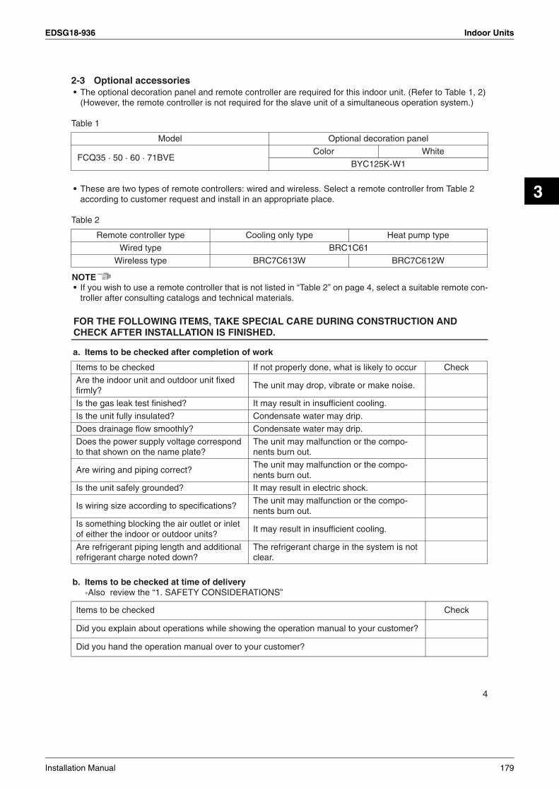
EDSG18-936 Indoor Units
3
2-3 Optional accessories• The optional decoration panel and remote controller are required for this indoor unit. (Refer to Table 1, 2)
(However, the remote controller is not required for the slave unit of a simultaneous operation system.)
Table 1
• These are two types of remote controllers: wired and wireless. Select a remote controller from Table 2 according to customer request and install in an appropriate place.
Table 2
NOTE• If you wish to use a remote controller that is not listed in “Table 2” on page 4, select a suitable remote con-
troller after consulting catalogs and technical materials.
FOR THE FOLLOWING ITEMS, TAKE SPECIAL CARE DURING CONSTRUCTION AND CHECK AFTER INSTALLATION IS FINISHED.
a. Items to be checked after completion of work
b. Items to be checked at time of delivery∗Also review the “1. SAFETY CONSIDERATIONS”
Model Optional decoration panel
FCQ35 · 50 · 60 · 71BVEColor White
BYC125K-W1
Remote controller type Cooling only type Heat pump type
Wired type BRC1C61
Wireless type BRC7C613W BRC7C612W
Items to be checked If not properly done, what is likely to occur Check
Are the indoor unit and outdoor unit fixed firmly?
The unit may drop, vibrate or make noise.
Is the gas leak test finished? It may result in insufficient cooling.
Is the unit fully insulated? Condensate water may drip.
Does drainage flow smoothly? Condensate water may drip.
Does the power supply voltage correspond to that shown on the name plate?
The unit may malfunction or the compo-nents burn out.
Are wiring and piping correct?The unit may malfunction or the compo-nents burn out.
Is the unit safely grounded? It may result in electric shock.
Is wiring size according to specifications?The unit may malfunction or the compo-nents burn out.
Is something blocking the air outlet or inlet of either the indoor or outdoor units?
It may result in insufficient cooling.
Are refrigerant piping length and additional refrigerant charge noted down?
The refrigerant charge in the system is not clear.
Items to be checked Check
Did you explain about operations while showing the operation manual to your customer?
Did you hand the operation manual over to your customer?
4
Installation Manual 179
Indoor Units EDSG18-936
c. Points for explanation about operations
2-4 Note to the installerBe sure to instruct customers how to properly operate the unit (especially cleaning filters, operating different functions, and adjusting the temperature) by having them carry out operations themselves while looking at the manual.
3. SELECTING INSTALLATION SITEPlease attach additional thermal insulation material to the unit body when it is believed that the relative humid-ity in the ceiling exceeds 80%. Use glass wool, polyethylene foam, or similar with a thickness of 10 mm or more as thermal insulation material.(1) Select an installation site where the following conditions are fulfilled and that meets your cus-
tomer’s approval.• In the upper space (including the back of the ceiling) of the indoor unit where there is no possible drip-
ping of water from the refrigerant pipe, drain pipe, water pipe, etc.• Where optimum air distribution can be ensured.• Where nothing blocks air passage.• Where condensate can be properly drained.• Where the ceiling is strong enough to bear the indoor unit weight.• Where the false ceiling is not noticeably on an incline.• Where sufficient clearance for maintenance and service can be ensured.• Where there is no risk of flammable gas leakage. • Where piping between indoor and outdoor units is possible within the allowable limit.
(Refer to the installation manual for the outdoor unit.)
CAUTION• Any vents, light fixtures, or other appliances which may disturb the airflow might cause the top side to
become dirty if located too nearby, so follow the figure below when installing.• Keep indoor unit, outdoor unit, power supply wiring and transmission wiring at least 1 meter away from
televisions and radios. This is to prevent image interference and noise in those electrical appliances.(Noise may be generated depending on the conditions under which the electric wave is generated, even if 1 meter is kept.)
(2) Ceiling height• Install this unit where the height of bottom panel is more than 2.5 m so that the user cannot easily touch.• This indoor unit may be installed on ceilings up to 3.5 m in height. However, it becomes necessary to
make field settings by remote controller and close the air outlet when installing the unit at a height over 2.7 m.Refer to the section entitled, “10. FIELD SETTING” and the decoration panel installation manual.
The items with WARNING and CAUTION marks in the operation manual are the items pertaining to possibilities for bodily injury and material damage in addition to the general usage of the product. Accordingly, it is necessary that you make a full explanation about the described contents and also ask your customers to read the operation manual.
5
180 Installation Manual

EDSG18-936 Indoor Units
3
(3) Use suspension bolts for installation. Check whether the ceiling is strong enough to support the weight of the unit or not. If there is a risk, reinforce the ceiling before installing the unit.(Installation pitch is maked on the paper pattern for installation. Refe
[Space required for installation]
r to it to check for points requiring reinforcing.)
NOTE• Leave 200 mm or more space where marked with the ∗, on sides where the air outlet is closed.
4. PREPARATIONS BEFORE INSTALLATION(1) Relation of ceiling opening to unit and suspension bolt position
∗≥1500
Air discharge ≥1
000
Airinlet
Air discharge
≥250
0Fo
r in
stal
latio
nin
hig
h pl
aces
.
∗≥1500
Fig. 1
Fig. 2
240
∗≥∗≥
∗≥∗≥
6
Installation Manual 181

Indoor Units EDSG18-936
Installation is possible when ceiling opening dimensions is as follows• When installing the unit within the frame for fixing false ceiling.
NOTE• Installation is possible with a ceiling dimension of 910 mm (marked with ∗). However, to achieve a ceiling-
panel overlapping dimension of 20 mm, the spacing between the ceiling and the unit should be 35 mm or less. If the spacing between ceiling and the unit is over 35 mm, attach ceiling material to part or recover the ceiling.
(2) Make the ceiling opening needed for installation where applicable. (For existing ceilings)• Refer to the paper pattern for installation (5) for ceiling opening dimensions.• Create the ceiling opening required for installation. From the side of the opening to the casing outlet,
implement the refrigerant and drain piping and wiring for remote controller (unnecessary for wireless type) and indoor-outdoor unit casing outlet. Refer to “6.REFRIGERANT PIPING WORK”, “7.DRAIN PIP-ING WORK” and “8.ELECTRIC WIRING WORK”.
• After making an opening in the ceiling, it may be necessary to reinforce ceiling beams to keep the ceiling level and to prevent it from vibrating. Consult the builder for details.
(3) Install the suspension bolts.(Use either a M8~M10 size bolt)Use a hole-in anchor for existing ceilings, and a sunken insert, sunken anchor or other field supplied parts for new ceilings to reinforce the ceiling to bear the weight of the unit. Adjust clearance (50~100mm) from the ceil-ing before proceeding further.
NOTE• All the above parts are field supplied.
860(Opening dimension inside the flame for ceiling)Frame
≥20 860~*910
(Ceiling-paneloverlapping dimension)
Falseceiling
(ceiling opening dimension)≥20
Fig. 6
≥ ≥
50 ~
100
Ceiling slab
Suspension bolt
Long nut or turn-buckleAnchor
False ceiling
<installation example>
Fig. 8
7
182 Installation Manual

EDSG18-936 Indoor Units
3
5. INDOOR UNIT INSTALLATIONInstalling optional accessories (except for the decoration panel) before installing the indoor unit is easier. However, for existing ceilings, install fresh air inlet component kit and branch duct before installing the unit.As for the parts to be used for installation work, be sure to use the provided accessories and specified parts designated by our company. <The two cushions provided on the top of the indoor unit serve to protect the floor from scratches or cracks when it is directly placed on the floor with the topside down. Be sure to remove the cushions before installa-tion.>Some models have no cushions.
(1) For new ceilings(1-1) Install the indoor unit temporarily.
• Attach the hanger bracket to the suspension bolt. Be sure to fix it securely by using a nut and washer (3) from the upper and lower sides of the hanger bracket.The washer fixing plate (7) will prevent the washer from falling.
(1-2) Refer to the paper pattern for installation (5) for ceiling opening dimension.Consult the builder or carpenter for details.•
•
The center of the ceiling opening is indicated on the paper pattern for installation.The center of the unit is indicated on the label attached to the unit and on the paper pattern for instal-lation.After removing the packaging material from the 4 corners of the paper pattern for installation (5), fix the paper pattern to the unit with screws (6) (×3).
• Ceiling height is shown on the side of the paper pattern for installation (5). Adjust the height of the unit according to this indication.
Field supply
Washer (3) (attached)
Hanger bracket
Tighten(double nuts)
[Securing the hanger bracket]
Fig. 10
8
Installation Manual 183
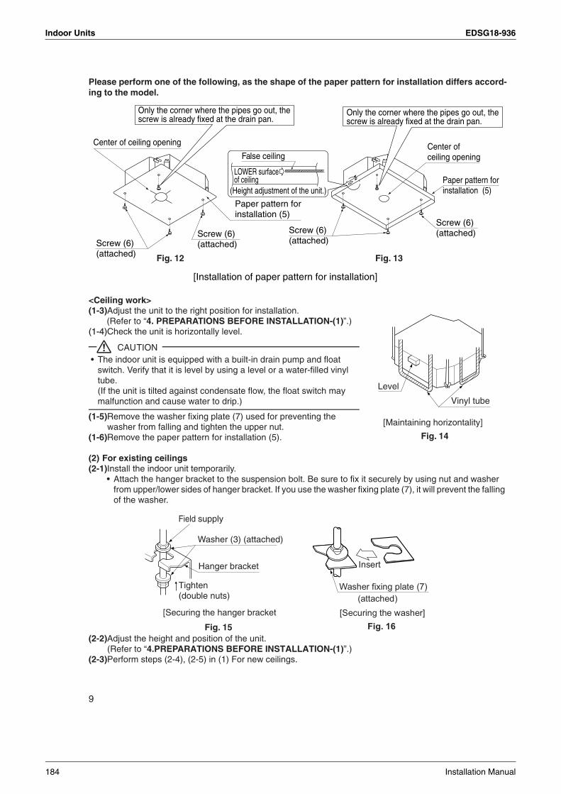
Indoor Units EDSG18-936
Please perform one of the following, as the shape of the paper pattern for installation differs accord-ing to the model.
<Ceiling work>(1-3) Adjust the unit to the right position for installation.
(Refer to “4. PREPARATIONS BEFORE INSTALLATION-(1)”.)(1-4) Check the unit is horizontally level.
CAUTION• The indoor unit is equipped with a built-in drain pump and float
switch. Verify that it is level by using a level or a water-filled vinyl tube.(If the unit is tilted against condensate flow, the float switch may malfunction and cause water to drip.)
(1-5) Remove the washer fixing plate (7) used for preventing the washer from falling and tighten the upper nut.
(1-6) Remove the paper pattern for installation (5).
(2) For existing ceilings(2-1) Install the indoor unit temporarily.
• Attach the hanger bracket to the suspension bolt. Be sure to fix it securely by using nut and washer from upper/lower sides of hanger bracket. If you use the washer fixing plate (7), it will prevent the falling of the washer.
(2-2) Adjust the height and position of the unit.(Refer to “4.PREPARATIONS BEFORE INSTALLATION-(1)”.)
(2-3) Perform steps (2-4), (2-5) in (1) For new ceilings.
Paper pattern forinstallation (5)
Only the corner where the pipes go out, the screw is already fixed at the drain pan.
Paper pattern forinstallation (5)
Screw (6)(attached)
False ceiling
[Installation of paper pattern for installation]
Center of ceiling opening
Screw (6)(attached)
LOWER surface of ceiling
(Height adjustment of the unit.)
Screw (6)(attached)
Screw (6)(attached)
Fig. 12 Fig. 13
Center of ceiling opening
Only the corner where the pipes go out, the screw is already fixed at the drain pan.
Level
Vinyl tube
[Maintaining horizontality]
Fig. 14
Field supply
Washer (3) (attached)
[Securing the hanger bracket
Hanger bracket
Tighten(double nuts)
Fig. 15
9
184 Installation Manual

EDSG18-936 Indoor Units
3
6. REFRIGERANT PIPING WORK<For refrigerant piping of outdoor unit and BP unit, see the installation manuals attached to the out-door unit and BP unit.><Execute heat insulation work completely on both sides of the gas piping and the liquid piping. Otherwise, awater leakage can result sometimes.>(When using a heat pump, the temperature of the gas piping can reach up to approximately 120°C, so useinsulation which is sufficiently resistant.)<Also, in cases where the temperature and humidity of the refrigerant piping sections might exceed 30°C orRH80%, reinforce the refrigerant insulation. (20 mm or thicker) Condensate may form on the surface of theinsulating material.><Be sure to check the type of refrigerant to be used before doing any work. (Using an incorrect refrigerant will prevent normal operation of the unit.)>
CAUTION• Use a pipe cutter and flare suitable for the type of refrigerant.• Apply ester oil or ether oil around the flare section before connecting.• To prevent dust, moisture or other foreign matter from infiltrating the tube, either pinch the end or cover it
with tape.• Do not allow anything other than the designated refrigerant to get mixed into the refrigerant circuit, such
as air, etc. If any refrigerant gas leaks while working on the unit, ventilate the room thoroughly right away.
• Be sure to use both a spanner and torque wrench together, as shown in the drawing, when connecting or disconnecting pipes to/from the unit. (Refer to Fig. 17)
• Refer to “Table 3” for the dimensions of flare nut spaces.• When connecting the flare nut, apply ester oil or ether oil to the flare
section (both inside and outside), and spin 3-4 times before screw-ing in. (Refer to Fig. 18)
NOTE• Use the flare nut included with the unit main body.
Table 3
∗When refrigerant is R22, the dimensions in parentheses ( ) can also be used.
• Refer to “Table 3” to de termine the proper tightening torque.
CAUTIONOver-tightening the flare nut may break it and/or cause the refrigerant to leak.
Pipe size Tightening torqueFlare dimensions
A (mm) ∗ Flare
φ 6.4
φ 9.5
φ 12.7
φ 15.9
14.2 – 17.2N • m (144 – 176 kgf • cm) 8.7 – 9.1 (8.3 – 8.7)
32.7 – 39.9N • m (333 – 407 kgf • cm) 12.8 – 13.2 (12.0 – 12.4)
49.5 – 60.3N • m (504 – 616 kgf • cm) 16.2 – 16.6 (15.4 – 15.8)
61.8 – 75.4N • m (630 – 770 kgf • cm) 19.3 – 19.7 (18.6 – 19.0)
Coat here with ester or ether oil
Fig. 18
Torque wrench
Spanner
Pipe union
Flare nutFig. 17
R0.4-0.8
A900
± 0.
50 45
0 ± 2
0
10
Installation Manual 185

Indoor Units EDSG18-936
Not recommendable but in case of emergency
You must use a torque wrench but if you are obliged to install the unit without a torque wrench, you mayfollow the installation method mentioned below
After the work is finished, make sure to check that there is no gas leak.
When you keep on tightening the flare nut with a spanner, there is a point where thetightening torque suddenly increases. From that position, further tighten the flare nut the angle shownbelow:
• Make absolutely sure to execute heat insulation works on the pipe-connecting section after checking gas leakage by thoroughly studying the following figure and using the attached heat insulating materials for fitting (8) and (9). (Fasten both ends with the clamps (4).) (Refer to Fig. 19)
• Wrap the sealing pad (11) only around the insulation for the joints on the gas piping side. (Refer to Fig. 19)
CAUTIONFor local insulation, be sure to insulate local piping all the way into the pipe connections inside the machine.Exposed piping may cause condensation or burns on contact.
CAUTIONCAUTION TO BE TAKEN WHEN BRAZING REFRIGERANT PIPING“Do not use flux when brazing refrigerant piping. Therefore, use the phosphor copper brazing filler metal (BCuP-2: JIS Z 3264/B-Cu93P-710/795: ISO 3677) which does not require flux.”(Flux has extremely harmful influence on refrigerant piping systems. For instance, if the chlorine based flux is used, it will cause pipe corrosion or, in particular, if the flux contains fluorine, it will damage the refrig-erant oil.)
• Before brazing local refrigerant piping, nitrogen gas shall be blown through the piping to expel air from the piping.If you brazing is done without nitrogen gas blowing, a large amount of oxide film develops inside the piping, and could cause system malfunction.
Pipe size Further tightening angle Recommended arm length of tool
φ 6.4 (1/4”) 60 to 90 degrees Approx. 150mm
φ 9.5 (3/8”) 60 to 90 degrees Approx. 200mm
φ 12.7 (1/2”) 30 to 60 degrees Approx. 250mm
φ 15.9 (5/8”) 30 to 60 degrees Approx. 300mm
Insulation for fitting (attached) (8)
(for gas line)
Medium sealing pad(attached) (11)
(Wrap the piping unionwith the sealing pad.)
Clamp (4)
(×4)
Gas pipingLiquid piping
Insulation for fitting(attached) (9)
(for liquid line)
Fig. 19
11
186 Installation Manual
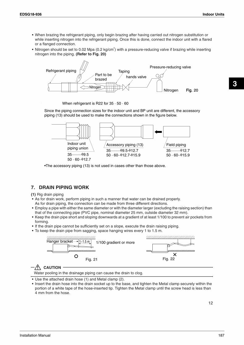
EDSG18-936 Indoor Units
3
• When brazing the refrigerant piping, only begin brazing after having carried out nitrogen substitution or while inserting nitrogen into the refrigerant piping. Once this is done, connect the indoor unit with a flared or a flanged connection.
• Nitrogen should be set to 0.02 Mpa (0.2 kg/cm2) with a pressure-reducing valve if brazing while inserting
nitrogen into the piping. (Refer to Fig. 20)
7. DRAIN PIPING WORK(1) Rig drain piping• As for drain work, perform piping in such a manner that water can be drained properly.
As for drain piping, the connection can be made from three different directions.• Employ a pipe with either the same diameter or with the diameter larger (excluding the raising section) than
that of the connecting pipe (PVC pipe, nominal diameter 25 mm, outside diameter 32 mm).• Keep the drain pipe short and sloping downwards at a gradient of at least 1/100 to prevent air pockets from
forming.• If the drain pipe cannot be sufficiently set on a slope, execute the drain raising piping.• To keep the drain pipe from sagging, space hanging wires every 1 to 1.5 m.
CAUTIONWater pooling in the drainage piping can cause the drain to clog.
• Use the attached drain hose (1) and Metal clamp (2).• Insert the drain hose into the drain socket up to the base, and tighten the Metal clamp securely within the
portion of a white tape of the hose-inserted tip. Tighten the Metal clamp until the screw head is less than 4 mm from the hose.
Refrigerant pipingPart to be brazed
TapingPressure-reducing valve
hands valve
Nitrogen Fig.Fig. 20Nitrogen
Indoor unitpiping union
Accessory piping (13)
35·········φ9.5-φ12.750 · 60··φ12.7-φ15.935·········φ9.5
50 · 60··φ12.7
Field piping
35·········φ12.750 · 60··φ15.9
Since the piping connection sizes for the indoor unit and BP unit are different, the accessory piping (13) should be used to mak
•The accessory piping (13) is not used in cases other than those above.
e the connections shown in the figure below.
When refrigerant is R22 for 35 · 50 · 60
1/100 gradient or more1~1.5 m
Fig. 21
Hanger bracket
Fig. 22
12
Installation Manual 187

Indoor Units EDSG18-936
• Wrap the attached sealing pad (10) over the Metal clamp and drain hose to insulate.• Make sure that heat insulation work is executed on the following 2 spots to prevent any possible water leak-
age due to dew condensation.• Indoor drain pipe• Drain socket
<PRECAUTIONS FOR DRAIN RAISING PIPING>• Install the drain raising pipes at a height of less than 550 mm.• Install the drain raising pipes at a right angle to the indoor unit and no more than 300 mm from the unit.
NOTE• To ensure no excessive pressure is applied to the included drain hose (1), do not bend or twist when install-
ing. (This may cause leakage.)• If converging multiple drain pipes, install according to the procedure shown below.
Select converging drain pipes whose gauge is suitable for the operating capacity of the unit.
(2) After piping work is finished, check if drainage flows smoothly.• Add approximately 2000 cc of water slowly from the inspection opening or the air outlet (Refer to Fig. 27)
and check drainage flow.
Metal clamp (2)
Tape (White)
Drain hose (1)
Fig. 23
Metal clamp (2) Large sealing pad (10)
(attached) (attached)
≤4 mm
Fig. 24
Drain hose (1) (accessory)
To prevent air bubbles in the drain hose part, keep it level or slightly tilted up. Any bubbles in the hose might cause the unit to make noise due to backflow when the drain pump stops.
Level or tilted slightly up
Ceiling slab
Metal clamp (attached) (2)
Drain raising pipe
Raising section
Drain hose (attached) (1)
≤750
Hanger bracket Adjustab(≤550)
1 ~ 1.5 m300 mm
200
Fig. 25
≥100
mm
T-joint converging drain pipes
Fig. 26
13
188 Installation Manual
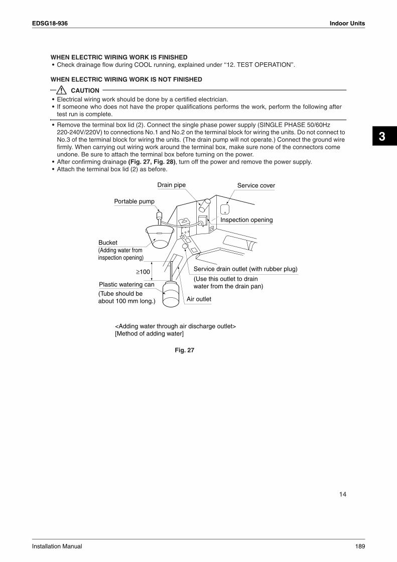
EDSG18-936 Indoor Units
3
WHEN ELECTRIC WIRING WORK IS FINISHED• Check drainage flow during COOL running, explained under ‘‘12. TEST OPERATION’’.
WHEN ELECTRIC WIRING WORK IS NOT FINISHED
CAUTION• Electrical wiring work should be done by a certified electrician.• If someone who does not have the proper qualifications performs the work, perform the following after
test run is complete.
• Remove the terminal box lid (2). Connect the single phase power supply (SINGLE PHASE 50/60Hz 220-240V/220V) to connections No.1 and No.2 on the terminal block for wiring the units. Do not connect to No.3 of the terminal block for wiring the units. (The drain pump will not operate.) Connect the ground wire firmly. When carrying out wiring work around the terminal box, make sure none of the connectors come undone. Be sure to attach the terminal box before turning on the power.
• After confirming drainage (Fig. 27, Fig. 28), turn off the power and remove the power supply.• Attach the terminal box lid (2) as before.
Drain pipe
Portable pump
Bucket(Adding water from inspection opening)
≥100
Plastic watering can
(Tube should be about 100 mm long.)
(Use this outlet to drainwater from the drain pan)
Service cover
Service drain outlet (with rubber plug)
Air outlet
Inspection opening
<Adding water through air discharge outlet>[Method of adding water]
Fig. 27
14
Installation Manual 189
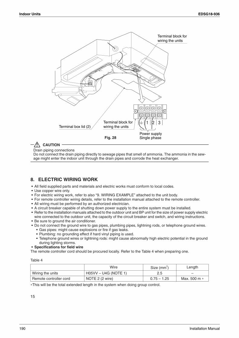
Indoor Units EDSG18-936
CAUTIONDrain piping connectionsDo not connect the drain piping directly to sewage pipes that smell of ammonia. The ammonia in the sew-age might enter the indoor unit through the drain pipes and corrode the heat exchanger.
8. ELECTRIC WIRING WORK• All field supplied parts and materials and electric works must conform to local codes.• Use copper wire only.• For electric wiring work, refer to also “9. WIRING EXAMPLE” attached to the unit body.• For remote controller wiring details, refer to the installation manual attached to the remote controller.• All wiring must be performed by an authorized electrician.• A circuit breaker capable of shutting down power supply to the entire system must be installed.• Refer to the installation manuals attached to the outdoor unit and BP unit for the size of power supply electric
wire connected to the outdoor unit, the capacity of the circuit breaker and switch, and wiring instructions.• Be sure to ground the air conditioner.• Do not connect the ground wire to gas pipes, plumbing pipes, lightning rods, or telephone ground wires.
• Gas pipes: might cause explosions or fire if gas leaks.• Plumbing: no grounding effect if hard vinyl piping is used. • Telephone ground wires or lightning rods: might cause abnormally high electric potential in the ground
during lighting storms.• Specifications for field wireThe remote controller cord should be procured locally. Refer to the Table 4 when preparing one.
Table 4
∗This will be the total extended length in the system when doing group control.
Wire Size (mm2) Length
Wiring the units H05VV – U4G (NOTE 1) 2.5 –
Remote controller cord NOTE 2 (2 wire) 0.75 – 1.25 Max. 500 m ∗
1 2 3Terminal box lid (2)
Terminal block forwiring the units
Power supply Single phase
Terminal block forwiring the units
Fig. 28
15
190 Installation Manual
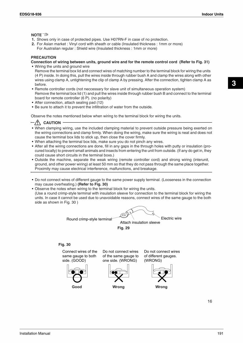
EDSG18-936 Indoor Units
3
NOTE1. Shows only in case of protected pipes. Use H07RN-F in case of no protection.2. For Asian market : Vinyl cord with sheath or cable (Insulated thickness : 1mm or more)
For Australian regular : Shield wire (Insulated thickness : 1mm or more)
PRECAUTIONConnection of wiring between units, ground wire and for the remote control cord (Refer to Fig. 31)• Wiring the units and ground wire
Remove the terminal box lid and connect wires of matching number to the terminal block for wiring the units (4 P) inside. In doing this, pull the wires inside through rubber bush A and clamp the wires along with other wires using clamp A, untightening the clip of clamp A by pressing. After the connection, tighten clamp A as before.
• Remote controller cords (not neccessary for slave unit of simultaneous operation system)Remove the terminal box lid (1) and pull the wires inside through rubber bush B and connect to the terminal board for remote controller (6 P). (no polarity)
• After connection, attach sealing pad (12)• Be sure to attach it to prevent the infiltration of water from the outside.
Observe the notes mentioned below when wiring to the terminal block for wiring the units.
CAUTION• When clamping wiring, use the included clamping material to prevent outside pressure being exerted on
the wiring connections and clamp firmly. When doing the wiring, make sure the wiring is neat and does notcause the terminal box lids to stick up, then close the cover firmly.
• When attaching the terminal box lids, make sure you do not pinch any wires.• After all the wiring connections are done, fill in any gaps in the through holes with putty or insulation (pro-
cured locally) to prevent small animals and insects from entering the unit from outside. (If any do get in, they could cause short circuits in the terminal boxs.)
• Outside the machine, separate the weak wiring (remote controller cord) and strong wiring (interunit,ground, and other power wiring) at least 50 mm so that they do not pass through the same place together.Proximity may cause electrical interference, malfunctions, and breakage.
• Do not connect wires of different gauge to the same power supply terminal. (Looseness in the connection may cause overheating.) (Refer to Fig. 30)
• Observe the notes when wiring to the terminal block for wiring the units.(Use a round crimp-style terminal with insulation sleeve for connection to the terminal block for wiring the units. In case it cannot be used due to unavoidable reasons, connect wires of the same gauge to the both side as shown in Fig. 30 )
Fig. 29
Fig. 30
Electric wireAttach insulation sleeve
Round crimp-style terminal
16
Installation Manual 191

Indoor Units EDSG18-936
Follow the instructions below if the wiring gets very hot due to slack in the power wiring.• In wiring, make certain that prescribed wires are used, carry out complete connections, and fix the wires so
that outside forces are not applied to the terminals.• Use the correct screwdriver for tightening the terminal screws. If the blade of screwdriver is too small, the
head of the screw might be damaged, and the screw will not be properly tightened.• If the terminal screw are tightened too hard, screws might be damaged.• Refer to the table below for the tightening torque of the terminal screws.
Tightening torque (N·m)
Terminal block for remote controller 0.79 to 0.97
Terminal block for wiring the units 1.18 to 1.44
P1 P2
Blue Blue Green
Noiseless earth
(In case a shield wire is used (P16 NOTE 2)) Remote controller cord(Shield wire)
∗Be sure to attach it to prevent the infiltration of water from the outside.
Rubber bush
Note)Wrap it around the wire without leaving any space
Sealing pad (small) (12) (Wrap it around the wire)
(Inside) (Outside)Wiring
(If there are more than 2 pieces of power supply wires, divide the sealing pad (small) (12) into some pieces and wrap them around each wire.)
Rubber bush B
Terminal block for remote controller (6P)
Terminal box lid (1)
Clamp A
Rubber bush A
Terminal block for wiring the units (4P)
[How to attach sealing pads]
WIRING DIAGRAM
Terminal box lid (2)
How to connect wiring
Note)
Fig. 31 Clip
Clamp A
Fig. 33
1 2 3
(Wiring the units and ground wire)How to connect terminal block for wiring the units (4P)
Fig. 32
17
192 Installation Manual
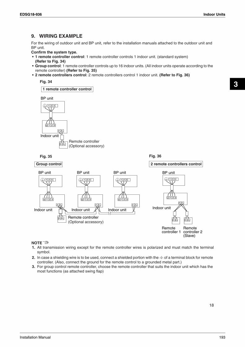
EDSG18-936 Indoor Units
3
9. WIRING EXAMPLEFor the wiring of outdoor unit and BP unit, refer to the installation manuals attached to the outdoor unit and BP unit.Confirm the system type.• 1 remote controller control: 1 remote controller controls 1 indoor unit. (standard system)
(Refer to Fig. 34)• Group control: 1 remote controller controls up to 16 indoor units. (All indoor units operate according to the
remote controller) (Refer to Fig. 35)• 2 remote controllers control: 2 remote controllers control 1 indoor unit. (Refer to Fig. 36)
NOTE1. All transmission wiring except for the remote controller wires is polarized and must match the terminal
symbol.2. In case a shielding wire is to be used, connect a shielded portion with the of a terminal block for remote
controller. (Also, connect the ground for the remote control to a grounded metal part.)3. For group control remote controller, choose the remote controller that suits the indoor unit which has the
most functions (as attached swing flap)
Fig. 34
Fig. 35 Fig. 36
1 2 3
P1 P2
1 2 3
P1 P2
BP unit
Indoor unit
Remote controller (Optional accessory)
1 remote controller control
P1 P2 P1 P2
1 2 3
P1 P2
Indoor unit
Remote controller 1
Remote controller 2 (Slave)
BP unit
1 2 3
2 remote controllers control
P1 P2
1 2 3 1 2 3 1 2 3
P1 P2 P1 P2 P1 P2
1 2 3 1 2 3 1 2 3
BP unit BP unit BP unit
Indoor unit
Remote controller(Optional accessory)
Indoor unit Indoor unit
Group control
18
Installation Manual 193
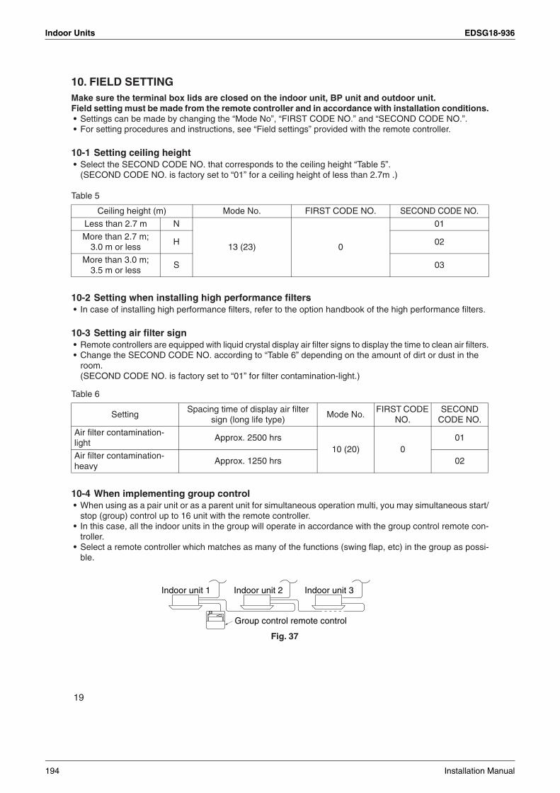
Indoor Units EDSG18-936
10. FIELD SETTINGMake sure the terminal box lids are closed on the indoor unit, BP unit and outdoor unit.Field setting must be made from the remote controller and in accordance with installation conditions.• Settings can be made by changing the “Mode No”, “FIRST CODE NO.” and “SECOND CODE NO.”.• For setting procedures and instructions, see “Field settings” provided with the remote controller.
10-1 Setting ceiling height• Select the SECOND CODE NO. that corresponds to the ceiling height “Table 5”.
(SECOND CODE NO. is factory set to “01” for a ceiling height of less than 2.7m .)
Table 5
10-2 Setting when installing high performance filters• In case of installing high performance filters, refer to the option handbook of the high performance filters.
10-3 Setting air filter sign• Remote controllers are equipped with liquid crystal display air filter signs to display the time to clean air filters.• Change the SECOND CODE NO. according to “Table 6” depending on the amount of dirt or dust in the
room.(SECOND CODE NO. is factory set to “01” for filter contamination-light.)
Table 6
10-4 When implementing group control• When using as a pair unit or as a parent unit for simultaneous operation multi, you may simultaneous start/
stop (group) control up to 16 unit with the remote controller.• In this case, all the indoor units in the group will operate in accordance with the group control remote con-
troller.• Select a remote controller which matches as many of the functions (swing flap, etc) in the group as possi-
ble.
Ceiling height (m) Mode No. FIRST CODE NO. SECOND CODE NO.
Less than 2.7 m N
13 (23) 0
01
More than 2.7 m;3.0 m or less
H 02
More than 3.0 m;3.5 m or less
S 03
SettingSpacing time of display air filter
sign (long life type)Mode No.
FIRST CODE NO.
SECOND CODE NO.
Air filter contamination-light
Approx. 2500 hrs10 (20) 0
01
Air filter contamination-heavy
Approx. 1250 hrs 02
Indoor unit 1 Indoor unit 2
Group control remote control
Indoor unit 3
Fig. 37
19
194 Installation Manual

EDSG18-936 Indoor Units
3
Wiring Method(1) Remove the terminal box lids. (See ‘‘8. ELECTRIC WIRING WORK’’.)(2) Cross-wire the terminal block for remote controller (P1 P2) inside the terminal box. (There is no
polarity.) (Refer to Fig. 35 on page 18 and Table 4 on page 15)
10-5 Control by 2 remote controllers (Controlling 1 indoor unit by 2 remote controllers)• When using 2 remote controllers, one must be set to “MAIN” and the other to “SUB”.
MAIN/SUB CHANGEOVER(1) Insert a screwdriver into the recess between the upper and lower part of remote controller and, work-
ing from the 2 positions, pry off the upper part. (The remote controller PC board is attached to the upper part of remote controller.) (Refer to Fig. 38)
(2) Turn the main/sub changeover switch on one of the two remote controller PC boards to “S”. (Leave the switch of the other remote controller set to “M”.) (Refer to Fig. 39)
Wiring Method (See ‘‘8. ELECTRIC WIRING WORK’’ on page 15)(3) Remove the terminal box lids.(4) Add remote control 2 (slave) to the terminal block for remote controller (P1, P2) in the terminal box.
(There is no polarity.) (Refer to Fig. 36 on page 18 and Table 4 on page 15)
11. INSTALLATION OF THE DECORATION PANEL<Read ‘‘12. TEST OPERATION’’ before making a test run without attaching the decorated panel.>Refer to the installation manual attached to the decoration panel.After installing the decoration panel, ensure that there is no space between the unit body and decoration panel.
12. TEST OPERATIONRefer to the section of “FOR THE FOLLOWING ITEMS, TAKE SPECIAL CARE DURING CONSTRUC-TION AND CHECK AFTER INSTALLATION IS FINISHED.” on page 4. • After finishing the construction of refrigerant piping, drain piping, and electric wiring, conduct test operation
accordingly to protect the unit.
12-1 How to test operation1. Open the gas side stop valve.2. Open the liquid side stop valve.3. Electrify crank case heater for 6 hours.4. Set to cooling operation with the remote controller and start operation by pushing ON/OFF button ( ).
Fig. 38 Fig. 39
20
Installation Manual 195

Indoor Units EDSG18-936
5. Press INSPECTION/TEST OPERATION button ( ) 4 times (2 times for wireless remote controller) and operate at Test Operation mode for 3 minutes.
6. Press AIR FLOW DIRECTION ADJUST button ( ) to make sure the unit is in operation.7. Press INSPECTION/TEST OPERATION button ( ) and operate normally.8. Confirm function of unit according to the operation manual.9. If the decoration panel has not been installed, turn off the power after the test operation.
PRECAUTIONS1. Refer to the diagnoses below if the unit does not operate properly.2. After completing the test run, press the INSPECTION/TEST OPERATION button once to put the unit in
inspection mode, and make sure the Malfunction code is “00”. (=normal)If the code reads anything other than “00”, refer to the malfunction diagnoses below.
NOTE• If a malfunction is preventing operation, refer to the malfunction diagnoses below.
12-2 Cautions for servicingWith the power on. Troubles can be monitored on the remote controller.• If the air conditioner does not operate normally after installing the air conditioner.
a malfunction shown in the table below may happened.
∗ After turning on the power, the maximum is 90 seconds, although it will only display “88”. This is not a prob-lem, and it will be set for 90 seconds.
Trouble shooting with the display on the liquid crystal display remote controller.1. With the wired remote controller. (NOTE 1)
When the operation stops due to trouble, operation lamp flashed, and “ ” and the Malfunction code are indicated on the liquid crystal display. In such a case, diagnose the fault contents by refering to the table on the Malfunction code list it case of group control, the unit No. is displayed so that the indoor unit no with the trouble can be recognized. (NOTE 2)
2. With the wireless remote controller.(Refer also to the operation manual attached to the wireless remote controller)When the operation stops due to trouble. the display on the indoor unit flashes. In such a case, diagnose the fault contents with the table on the Malfunction code list looking for the Malfunction code which can be found by following procedures. (NOTE 2)
(1) Press the INSPECTION /TEST OPERATION button, “ ” is displayed and “ 0 ” flashes.(2) Press the PROGRAMMING TIME button and find the unit No. which stopped due to trouble.
Number of beeps 3 short beeps Perform all the following operations 1 short beep Perform (3) and (6)1 long beep No trouble
(3) Press the OPERATION MODE SELECTOR button and upper figure of the Malfunction code flashes.(4) Continue pressing the PROGRAMMING TIME button unit it makes 2 short beeps and find the upper
code.(5) Press the Operation selector button and lower figure of the Malfunction code flashes.(6) Continue pressing the PROGRAMMING TIME button unit it makes a long beep and find the lower code.
• A long beep indicate the Malfunction code.
Remote control display Malfunction
No display
• Power supply trouble or Open phase connection• Wrong wiring between indoor and outdoor unit• Indoor PC board faulty• Wrong remote control conection wiring• Remote control faulty• Fuse faulty
88∗ • Indoor PC board faulty• Wrong wiring between indoor and outdoor unit
88 flashing • Wrong wiring between indoor and outdoor unit
TEST
TEST
21
196 Installation Manual

EDSG18-936 Indoor Units
3
NOTE1. In case wired remote controller. Press the INSPECTION /TEST OPERATION button on remote controller,
“ ” starts flashing and changes the inspection mode.2. Keep down the ON/OFF button for 5 seconds or longer in the inspection mode and the above trouble his-
tory disappears, after the Malfunction code goes on and off twice, followed by the code “00” (normal).The display changes from the inspection mode to the normal mode.
12-3 Malfunction code list• For plases where the Malfunction code is left blank, the “ ” indication is not displayed. Though the system
continues operating, be sure to inspect the system and make repairs as necessary.• Depending on the type of indoor or outdoor unit, the Malfunction code may or may not be displayed.
Code Malfunction/Remarks
A1 Indoor unit’s PC board faulty
A3 Drain water level abnormal
A6 Indoor fan motor overloaded, overcurrent or locked
AF Humidifier faulty
AHAir cleaner faulty
Only the air cleaner does not function.
AJType set improper
Capacity data is wrongly preset. Or there is nothing programmed in the data hold IC.
C4 Sensor (R2T) for heat exchanger temperature is fault
C5 Sensor (R3T) for heat exchanger temperature is fault
C9 Sensor for suction air temperature is fault
CJSensor for remote controller is fault
The remote controller thermistor does not function, but the system thermo run is possible.
E0 Action of safety device (outdoor unit)
E1 Outdoor unit’s PC board faulty
E3 High pressure abnormal(outdoor unit)
E4 Low pressure abnormal (outdoor unit)
E5 Compressor motor lock malfunction
E7Outdoor fan motor lock malfunctionOutdoor fan instantaneous overcurrent malfunction
E9 Electronic expansion valve faulty (outdoor unit)
F3 Discharge pipe temperature abnormal (outdoor unit)
H3 High pressure switch faulty (outdoor unit)
H4 Low pressure switch faulty (outdoor unit)
H7 Outdoor motor position signal malfunction
H9 Outdoor air thermistor faulty (outdoor unit)
J3 Discharge pipe thermistor faulty (outdoor unit)
J5 Suction pipe thermistor faulty (outdoor unit)
J6 Heat exchanger thermistor faulty (outdoor unit)
L4Overheated heat-radiating fin (outdoor unit)
Inverter cooling defect.
L5Instantaneous overcurrent (outdoor unit)
Possible earth fault or short circuit in the compressor motor.
L8Electric thermal (outdoor unit)
Possible electrical overload in the compressor or cut line in the compressor motor.
22
Installation Manual 197

Indoor Units EDSG18-936
L9Stall prevention (outdoor unit)
Compressor possibly locked.
LC Transmission malfunction between the outdoor control units’ inverters (outdoor unit)
P1 Open-phase (outdoor unit)
P3 P-board temperature sensor malfunction (outdoor unit)
P4 Heat-radiating fin temperature sensor malfunction (outdoor unit)
PJType set improper (outdoor unit)
Capacity data is wrongly preset. Or there is nothing programmed in the data hold IC.
U0 Suction pipe temperature abnormal
U1Reverse phase
Reverse two of the L1, L2 and L3 leads.
U2Power source voltage malfunction
Includes the defect in 52C.
U4UF
Transmission error (indoor unit – outdoor unit)
Wrong wiring between indoor and outdoor units or malfunction of the PC board mounted on the indoor and the outdoor units.If UF is shown, the wiring between the indoor and outdoor units is not properly wired. Therefore, immediately disconnect the power supply and correct the wiring. (The compressor and the fan mounted on the outdoor unit may start operation inde-pendent of the remote controller operation.)
U5Transmission error (indoor unit – remote controller)
Transmission is improper between the indoor unit and the remote controller.
U8 Malfunction in transmission between main and sub remote controls. (Malfunction in sub remote control.)
UAMiss setting for multi system
Setting is wrong for selector switch of multi-system. (see switch SS2 on the main unit’s PC board)
UC Central control address overlapping
23
3P156215-2C
198 Installation Manual

EDSG18-936 Indoor Units
3
3.9 Ceiling Mounted Built-in Type FBQ60/71B
1. SAFETY CONSIDERATIONSPlease read these “SAFETY CONSIDERATIONS” carefully before installing air conditioning equipment and be sure to install it correctly. After completing the installation, make sure that the unit operates properly during the start-up operation. Please instruct the customer on how to operate the unit and keep it maintained.Also, inform customers that they should store this installation manual along with the operation manual for future reference.This air conditioner comes under the term “appliances not accessible to the general public”.
Meaning of warning and caution symbols.
WARNING .........Failure to observe a warning may result in death.
CAUTION ..........Failure to observe a caution may result in injury or damage to the equipment.
WARNING• Ask your dealer or qualified personnel to carry out installation work. Do not try to install the air conditioner
yourself.Improper installation may result in water leakage, electric shocks or fire.
• Perform installation work in accordance with this installation manual.Improper installation may result in water leakage, electric shocks or fire.
• Be sure to use only the specified accessories and parts for installation work.Failure to use the specified parts may result in water leakage, electric shocks, fire or the unit falling.
• Install the air conditioner on a foundation strong enough to withstand the weight of the unit.A foundation of insufficient strength may result in the equipment falling and causing injuries.
• Carry out the specified installation work after considering strong winds, typhoons or earthquakes. Improper installation work may result in the equipment falling and causing accidents.
• Make sure that a separate power supply circuit is provided for this unit and that all electrical work is carried out by qualified personnel according to local laws and regulations and this installation manual.An insufficient power supply capacity or improper electrical construction may lead to electric shocks or fire.
• Make sure that all wiring is secured, the specified wires and used, and no external forces act on the terminal connections or wires.Improper connections or installation may result in fire.
• When wiring the power supply and connecting the wiring between the indoor and outdoor units, position the wires so that the control box lid can be securely fastened.Improper positioning of the control box lid may result in electric shocks, fire or the terminals overheating.
• If the refrigerant gas leaks during installation, ventilate the area immediately.Toxic gas may be produced if the refrigerant gas comes into contact with fire.
• After completing the installation work, check that the refrigerant gas does not leak.Toxic gas may be produced if the refrigerant gas leaks into the room and comes into contact with a source of fire, such as a fan heater, stove or cooker.
• Before touching electrical parts, turn off the unit.
1
Installation Manual 199
Indoor Units EDSG18-936
CAUTION• Ground the air conditioner.
Do not connect the ground wire to gas or water pipes, lightning conductor or a telephone ground wire.Incomplete grounding may result in electric shocks.
• Be sure to install an earth leakage breaker.Failure to install an earth leakage breaker may result in electric shocks.
• While following the instructions in this installation manual, install drain piping in order to ensure proper drainage and insulate piping in order to prevent condensate.Improper drain piping may result in water leakage and property damage.
• Install the indoor and outdoor units, power supply wiring and connecting wiring at least 1 meter away from televisions or radios in order to prevent image interference or noise.(Depending on the radio waves, a distance of 1 meter may not be sufficient enough to eliminate the noise.)
• Remote controller (wireless kit) transmitting distance can result shorter than expected in rooms with elec-tronic fluorescent lamps (inverter or rapid start types). Install the indoor unit as far away from fluorescent lamps as possible.
• Do not install the air conditioner in the following locations:(a)where a mineral oil mist or an oil spray or vapor is produced, for example in a kitchen
Plastic parts may deteriorate and fall off or result in water leakage.(b)where corrosive gas, such as sulfurous acid gas, is produced
Corroding copper pipes or soldered parts may result in refrigerant leakage.(c)near machinery emitting electromagnetic waves
Electromagnetic waves may disturb the operation of the control system and result in a malfunction of the equipment.
(d)where flammable gases may leak, where there are carbon fiber or ignitable dust suspensions in the air, or where volatile flammables such as thinner or gasoline are handled.Operating the unit in such conditions may result in fire.
2. BEFORE INSTALLATION• Do not exert pressure on the resin parts when opening the unit or when moving it after opening.• Be sure to check the type of refrigerant to be used before installing the unit. (Using an incorrect refrigerant
will prevent normal operation of the unit.)• The accessories needed for installation must be retained in your custody until the installation work is com-
pleted. Do not discard them!• Decide upon a line of transport.• Leave the unit inside its packaging while moving, until reaching the installation site. Where unpacking is
unavoidable, use a sling of soft material or protective plates together with a rope when lifting, to avoid dam-age or scratches to the unit.
• When selecting installation site, refer to the paper pattern.• For the installation of an outdoor unit, refer to the installation manual attached to the outdoor unit.• Do not use the unit in locations with high salt content in the air such as beachfront property, locations where
the voltage fluctuates such as factories, or in automobiles or marine vessels.
1. Precautions• Be sure to read this manual before installing the indoor unit.• When selecting installation site, refer to the paper pattern.• This unit is suitable for installation in a household, commercial and light industrial environment.• Do not install or operate the unit in rooms mentioned below.
• Laden with mineral oil, or filled with oil vapor or spray like in kitchens. (Plastic parts may deteriorate.)• Where corrosive gas like sulfurous gas exists. (Copper tubing and brazed spots may corrode.)• Where volatile flammable gas like thinner or gasoline is used.• Where machines can generate electromagnetic waves. (Control system may malfunction.)• Where the air contains high levels of salt such as that near the ocean and where voltage fluctuates
greatly such as that in factories. Also in vehicles or vessels.
2
200 Installation Manual

EDSG18-936 Indoor Units
3
2. AccessoriesCheck if the following accessories are included with your unit.
• Screws for fixing panels are attached to decoration panel.
Name (1) Metal clamp(2) Paper pat-
tern for installation
(3) Drain hoseInsulation for
fittingSealing pad
Quantity 1 pc. 1 pc. 1 pc. 1 each 1 each
Shape
(4) For gas pipe
(5) For liquid pipe
(6) Large
(7) Middle
Name(8) Washer for
hanger bracketClamp
(11) Screws for fixing the paper pattern for installation
(12) Duct companion flange connec-tion screw
Quantity 8 pcs. 6 pcs. 3 pcs. 6 pcs. 12 pcs.
Shape
(9) Large (10) Small
Name (13) Small sealing pad
(Other)• Operation manual• Installation manual
Quantity 2 pcs.
Shape
3
Installation Manual 201
Indoor Units EDSG18-936
3. Optional accessories• For this indoor unit, the optional remote controller is necessary. In case of downward air inlet, the dec-
oration panel and the canvas for decoration panel are necessary. (Refer to “4. PREPARATIONS BEFORE INSTALLATION”)
• Remote controller
NOTE• If the customer wishes to use a remote controller that is not listed on the table, select a suitable remote
controller after consulting catalogs and technical materials.
• Use the decoration panel which apply to the below table.
∗ When using the canvas duct for the decoration panel, the decoration panel needs at least 42.5 cm of ceiling space.
FOR THE FOLLOWING ITEMS, TAKE SPECIAL CARE DURING CONSTRUCTION AND CHECK AFTER INSTALLATION IS FINISHED.
a. Items to be checked after completion of work
b. Items to be checked at time of delivery∗Also review the “1. SAFETY CONSIDERATIONS”
Remote controller BRC1C61
Model Min. height above ceilingDecoration panel Canvas duct for
decoration panelColor White
FBQ60BV1FBQ71BV1FBQ60BVLFBQ71BVL
∗
BYBS71DJW1
KSAJ25K80
35 cm or more Installation not required ∗
Items to be checked If not properly done, what is likely to occur Check
Are the indoor unit and outdoor unit fixed firmly?
The unit may drop, vibrate or make noise.
Is the gas leak test finished? It may result in insufficient cooling.
Is the unit fully insulated? Condensate water may drip.
Does drainage flow smoothly? Condensate water may drip.
Does the power supply voltage correspond to that shown on the name plate?
The unit may malfunction or the compo-nents burn out.
Are wiring and piping correct?The unit may malfunction or the compo-nents burn out.
Is the unit safely grounded? It may result in electric shock.
Is wiring size according to specifications?The unit may malfunction or the compo-nents burn out.
Is something blocking the air outlet or inlet of either the indoor or outdoor units?
It may result in insufficient cooling.
Are refrigerant piping length and additional refrigerant charge noted down?
The refrigerant charge in the system is not clear.
Items to be checked Check
Did you explain about operations while showing the operation manual to your customer?
Did you hand the operation manual over to your customer?
4
202 Installation Manual

EDSG18-936 Indoor Units
3
c. Points for explanation about operations
4. Note to the installerBe sure to instruct customers how to properly operate the unit (especially cleaning filters, operating dif-ferent functions, and adjusting the temperature) by having them carry out operations themselves while looking at the manual.
3. SELECTING INSTALLATION SITEPlease attach additional thermal insulation material to the unit body when it is believed that the relative humid-ity in the ceiling exceeds 80%. Use glass wool, polyethylene foam, or similar with a thickness of 10 mm or more as thermal insulation material.
1. Select an installation site where the following conditions are fulfilled and that meets your customer’s approval.• In the upper space (including the back of the ceiling) of the indoor unit where there is no possible
dripping of water from the refrigerant pipe, drain pipe, water pipe, etc.• Where optimum air distribution can be ensured.• Where nothing blocks air passage.• Where condensate can be properly drained.• Where the ceiling is strong enough to bear the indoor unit weight.• Where the false ceiling is not noticeably on an incline.• Where sufficient clearance for maintenance and service can be ensured.• Where there is no risk of flammable gas leakage.• Where piping between indoor and outdoor units is possible within the allowable limit. (Refer to the
installation manual for the outdoor unit.)
CAUTION• Keep indoor unit, outdoor unit, power supply wiring and transmission wiring at least 1 meter away from
televisions and radios. This is to prevent image interference and noise in those electrical appliances.(Noise may be generated depending on the conditions under which the electric wave is generated, even if 1 meter is kept.)
2. Use suspension bolts for installation. Check whether the ceiling is strong enough to support the weight of the unit or not. If there is a risk, reinforce the ceiling before installing the unit.(Installation pitch is marked on the paper pattern for installation. Refer to it to check for points requiring reinforcement.)
The items with WARNING and CAUTION marks in the operation manual are the items pertaining to possibilities for bodily injury and material damage in addition to the general usage of the product. Accordingly, it is necessary that you make a full explanation about the described contents and also ask your customers to read the operation manual.
300 or more
(Service space)
Drain pipe
Power supply wiring port
Liquid pipe
Gas pipe
Transmission wiring port
Maintenancedrain hose
2500 or higher from the floorFor installationin high placesFloor
Required service space
5
Installation Manual 203

Indoor Units EDSG18-936
4. PREPARATIONS BEFORE INSTALLATION1. Relation of ceiling opening to unit and suspension bolt position. (Refer to Fig. 1)
For standard installation (air inlet on the both side), choose one of the below two means of installation.NOTE• For other than standard installation, contact your Daikin dealer for details.
2. The fan speed for this indoor unit is preset to provide standard external static pres-sure.• If higher or lower external static pressure is required, reset the external static pressure by changing
the initial setting from the remote controller. Refer to the section entitled “10. FIELD SETTING”.
Indoor unit
Suspension bolt (×4)10
00 (I
ndoo
r uni
t)10
50(S
uspe
nsio
n bo
lt pi
tch)
Pipe 630145
(Suspension bolt pitch)
800 (Indoor unit)
Fig. 1
180
or m
ore
425
120
(120
-300
)
Decoration panel(Optional accessory)
462(Ceiling opening)
Canvas duct fordecoration panel(Optional accessory)
Ceilingsurface
Indoor unit(Back side)
(Ceiling opening)1060
For mounting decoration panel with canvas duct
1060
For mounting decoration panel directly
180
350
or m
ore
Decoration panelCeilingsurface
(Ceiling opening)
462
Indoor unit(Back side)
(Ceiling opening)
6
204 Installation Manual

EDSG18-936 Indoor Units
3
3. Install the suspension bolts. (Refer to Fig. 2)(Use M10 size bolt for the suspension bolt)Use anchors for existing ceilings, and a sunken insert, sunken anchor or other field supplied parts for new ceil-ings to reinforce the ceiling to bear the weight of the unit.
NOTE• All the above parts are field supplied.
5. INDOOR UNIT INSTALLATION<When installing optional accessories (except for the decoration panel), read also the installation manual for optional accessories.Depending on the field conditions, it may be easier to install optional accessories before the indoor unit is installed.>Be sure to use the furnished accessories or ones that match the specifications when installing.
1. Install the indoor unit temporarily.• Attach the hanger bracket to the suspension bolt. Be sure to
fix it securely by using a nut and washer (8) from the upper and lower sides of the hanger bracket. (Refer to Fig. 3)
2. Check the unit is horizontally level. (Refer to Fig. 4)
CAUTION• The indoor unit is equipped with a built-in drain pump and float switch. Verify that it is level by using a level
or a water-filled vinyl tube.(If the unit is tilted against condensate flow, the float switch may malfunction and cause water to drip.)
3. Tighten the upper nut.
4. Fix the installation paper pattern• The paper pattern for installation corre-
sponds with the measurements of the ceil-ing opening. Consult the builder for details.
• Attach the paper pattern for installation to the unit with the attached screws. (Refer to Fig. 5)The paper pattern for installation is marked for 3 types of ceiling openings. Read the notations carefully when installing.
Ceiling slab
Long nut or turn-buckle
Suspension boltIndoor unit
<Installation example>
Anchor
Fig. 2
Field supply(8)Washer for hanger bracket (attached)
Tighten (double nuts)
Fig. 3
Vinyl tube
Level
Fig. 4
(2) Paper pattern for installation (attached)
(11) Screws for fixing the paper pattern for installation (×6 attached)Fig. 5
7
Installation Manual 205

Indoor Units EDSG18-936
6. REFRIGERANT PIPING WORK<For refrigerant piping of outdoor unit and BP unit, see the installation manuals attached to the out-door unit and BP unit.><Execute heat insulation work completely on both sides of the gas piping and the liquid piping. Otherwise, a water leakage can result sometimes.>(When using a heat pump, the temperature of the gas piping can reach up to approximately 120°C, so use insulation which is sufficiently resistant.)<Also, in cases where the temperature and humidity of the refrigerant piping sections might exceed 30°C or RH80%, reinforce the refrigerant insulation. (20 mm or thicker) Condensate may form on the surface of the insulating material.><Be sure to check the type of refrigerant to be used before doing any work. (Using an incorrect refrigerant will prevent normal operation of the unit.)>
CAUTION• Use a pipe cutter and flare suitable for the type of refrigerant.• Apply ester oil or ether oil around the flare section before connecting.• To prevent dust, moisture or other foreign matter from infiltrating the tube, either pinch the end or cover it
with tape.• Do not allow anything other than the designated refrigerant to get mixed into the refrigerant circuit, such as
air, etc. If any refrigerant gas leaks while working on the unit, ventilate the room thoroughly right away.
• Be sure to use both a spanner and torque wrench together, as shown in the drawing, when connecting or disconnecting pipes to/from the unit. (Refer to Fig. 6)
• Refer to “Table 1” for the dimensions of flare nut spaces.• When connecting the flare nut, apply ester oil or ether oil to the flare
section (both inside and outside), and spin 3-4 times before screwing in. (Refer to Fig. 7)
NOTE• Use the flare nut included with the unit main body.
Table 1
• Refer to “Table 1” to determine the proper tightening torque.
CAUTIONOver-tightening the flare nut may break it and/or cause the refrigerant to leak.
Pipe size Tightening torqueFlare dimensions
A (mm) Flare
φ 6.4 14.2 – 17.2N • m (144 – 176 kgf • cm) 8.7 – 9.1
φ 9.5 32.7 – 39.9N • m (333 – 407 kgf • cm) 12.8 – 13.2
φ 12.7 49.5 – 60.3N • m (504 – 616 kgf • cm) 16.2 – 16.6
φ 15.9 61.8 – 75.4N • m (630 – 770 kgf • cm) 19.3 – 19.7
Torque wrench
Spanner
Pipe union
Flare nutFig. 6
Coat here with ester or ether oil
Fig. 7
R0.4-0.8
A900
± 0.
50 45
0 ± 2
0
8
206 Installation Manual
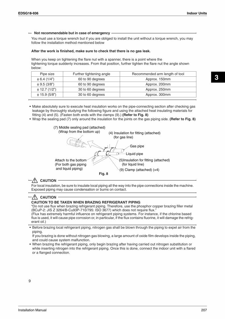
EDSG18-936 Indoor Units
3
Not recommendable but in case of emergency
You must use a torque wrench but if you are obliged to install the unit without a torque wrench, you mayfollow the installation method mentioned below
After the work is finished, make sure to check that there is no gas leak.
When you keep on tightening the flare nut with a spanner, there is a point where thetightening torque suddenly increases. From that position, further tighten the flare nut the angle shownbelow:
• Make absolutely sure to execute heat insulation works on the pipe-connecting section after checking gas leakage by thoroughly studying the following figure and using the attached heat insulating materials for fitting (4) and (5). (Fasten both ends with the clamps (9).) (Refer to Fig. 8)
• Wrap the sealing pad (7) only around the insulation for the joints on the gas piping side. (Refer to Fig. 8)
CAUTIONFor local insulation, be sure to insulate local piping all the way into the pipe connections inside the machine.Exposed piping may cause condensation or burns on contact.
CAUTIONCAUTION TO BE TAKEN WHEN BRAZING REFRIGERANT PIPING“Do not use flux when brazing refrigerant piping. Therefore, use the phosphor copper brazing filler metal (BCuP-2: JIS Z 3264/B-Cu93P-710/795: ISO 3677) which does not require flux.”(Flux has extremely harmful influence on refrigerant piping systems. For instance, if the chlorine based flux is used, it will cause pipe corrosion or, in particular, if the flux contains fluorine, it will damage the refrig-erant oil.)
• Before brazing local refrigerant piping, nitrogen gas shall be blown through the piping to expel air from the piping.If you brazing is done without nitrogen gas blowing, a large amount of oxide film develops inside the piping, and could cause system malfunction.
• When brazing the refrigerant piping, only begin brazing after having carried out nitrogen substitution or while inserting nitrogen into the refrigerant piping. Once this is done, connect the indoor unit with a flared or a flanged connection.
Pipe size Further tightening angle Recommended arm length of tool
φ 6.4 (1/4”) 60 to 90 degrees Approx. 150mm
φ 9.5 (3/8”) 60 to 90 degrees Approx. 200mm
φ 12.7 (1/2”) 30 to 60 degrees Approx. 250mm
φ 15.9 (5/8”) 30 to 60 degrees Approx. 300mm
(9) Clamp (attached) (×4)
Gas pipe
Liquid pipe
(5)Insulation for fitting (attached) (for liquid line)
(4) Insulation for fitting (attached) (for gas line)
Attach to the bottom(For both gas piping and liquid piping)
(7) Middle sealing pad (attached) (Wrap from the bottom up)
Fig. 8
9
Installation Manual 207

Indoor Units EDSG18-936
• Nitrogen should be set to 0.02 Mpa (0.2 kg/cm2) with a pressure-reducing valve if brazing while inserting
nitrogen into the piping. (Refer to Fig. 9)
7. DRAIN PIPING WORK1. Rig drain piping (Refer to Fig. 10, Fig. 11)
• As for drain work, perform piping in such a manner that water can be drained properly.As for drain piping, the connection can be made from three different directions.
• Employ a pipe with either the same diameter or with the diameter larger (excluding the raising section) than that of the connecting pipe (PVC pipe, nominal diameter 25 mm, outside diameter 32 mm).
• Keep the drain pipe short and sloping downwards at a gradient of at least 1/100 to prevent air pockets from forming.
• If the drain pipe cannot be sufficiently set on a slope, execute the drain raising piping.• To keep the drain pipe from sagging, space hanging wires every 1 to 1.5 m.
CAUTIONWater pooling in the drainage piping can cause the drain to clog.
• Use the attached drain hose (3) and Metal clamp (1).• Insert the drain hose into the drain socket up to the base, and tighten the Metal clamp securely within
the portion of a white tape of the hose-inserted tip. Tighten the Metal clamp until the screw head is less than 4 mm from the hose.
• Wrap the attached sealing pad (6) over the Metal clamp and drain hose to insulate.• Make sure that heat insulation work is executed on the following 2 spots to prevent any possible water
leakage due to dew condensation.• Indoor drain pipe• Drain socket
Refrigerant pipingPart to be brazed
TapingPressure-reducing valve
hands valve
Nitrogen Fig. 9Nitrogen
1/100 gradient or more1~1.5 m
Fig. 10
Hanger bracket
Fig. 11
Metal clamp (1)
Tape (White)
Drain hose (3)
Fig. 12
Metal clamp (1) Large sealing pad (6)
(attached) (attached)
4 mm
Fig. 13
≥
10
208 Installation Manual
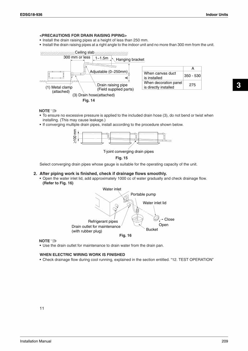
EDSG18-936 Indoor Units
3
<PRECAUTIONS FOR DRAIN RAISING PIPING>• Install the drain raising pipes at a height of less than 250 mm.• Install the drain raising pipes at a right angle to the indoor unit and no more than 300 mm from the unit.
NOTE• To ensure no excessive pressure is applied to the included drain hose (3), do not bend or twist when
installing. (This may cause leakage.)• If converging multiple drain pipes, install according to the procedure shown below.
Select converging drain pipes whose gauge is suitable for the operating capacity of the unit.
2. After piping work is finished, check if drainage flows smoothly.• Open the water inlet lid, add approximately 1000 cc of water gradually and check drainage flow.
(Refer to Fig. 16)
NOTE• Use the drain outlet for maintenance to drain water from the drain pan.
WHEN ELECTRIC WIRING WORK IS FINISHED• Check drainage flow during cool running, explained in the section entitled. “12. TEST OPERATION”
(3) Drain hose(attached)
Drain raising pipe(Field supplied parts)
Hanging bracket
(1) Metal clamp (attached)
1~1.5m300 mm or less
Adjustable (0~250mm)
Fig. 14
A
Ceiling slab
A
350 - 530
275
When canvas duct is installedWhen decoration panel is directly installed
≥100
mm
T-joint converging drain pipes
Fig. 15
Water inlet
Refrigerant pipesDrain outlet for maintenance(with rubber plug) Bucket
CloseOpen
Water inlet lid
Portable pump
Fig. 16
11
Installation Manual 209

Indoor Units EDSG18-936
WHEN ELECTRIC WIRING WORK IS NOT FINISHED
CAUTION• Electrical wiring work should be done by a certified electrician.• If someone who does not have the proper qualifications performs the work, perform the following after
test run is complete.
• Remove the control box lid. Connect the single phase power supply (SINGLE PHASE 50/60Hz 220-240V/220V) to connections No.1 and No.2 on the terminal block for wiring the units. Do not con-nect to No.3 of the terminal block for wiring the units. (The drain pump will not operate.) Connect the ground wire firmly. When carrying out wiring work around the control box, make sure none of the con-nectors come undone. Be sure to attach the control box before turning on the power.
• After confirming drainage (Fig. 16, Fig. 17), turn off the power and remove the power supply.• Attach the control box lid as before.
8. ELECTRIC WIRING WORK• All field supplied parts and materials and electric works must conform to local codes.• Use copper wire only.• For electric wiring work, refer also to “13. WIRING DIAGRAM” • For remote controller wiring details, refer to the installation manual attached to the remote controller.• All wiring must be performed by an authorized electrician.• A circuit breaker capable of shutting down power supply to the entire system must be installed.• Refer to the installation manual attached to the outdoor unit and BP unit for the size of power supply electric
wire connected to the outdoor unit, the capacity of the circuit breaker and switch, and wiring instructions.• Be sure to ground the air conditioner• Do not connect the ground wire to gas pipes, plumbing pipes, lightning rods, or telephone ground wires.
• Gas pipes: might cause explosions or fire if gas leaks.• Plumbing: no grounding effect if hard vinyl piping is used. • Telephone ground wires or lightning rods: might cause abnormally high electric potential in the ground
during lighting storms.
• Specifications for field wireThe remote controller cord should be procured locally. Refer to the Table 2 when preparing one.
Table 2
NOTE1. Shows only in case of protected pipes. Use H07RN-F in case of no protection.2. For Asian market : Vinyl cord with sheath or cable (Insulated thickness : 1mm or more)
For Australian regular : Shield wire (Insulated thickness : 1mm or more)
Wire Size (mm2) Length
Wiring the units H05VV - U4G (NOTE 1) 2.5 -
Remote controller cord (NOTE 2) (2 wires) 0.75 - 1.25 Max. 500 m
1 2 3
Control box
Terminal block for wiring
Single phase power supplyFig. 17
12
210 Installation Manual
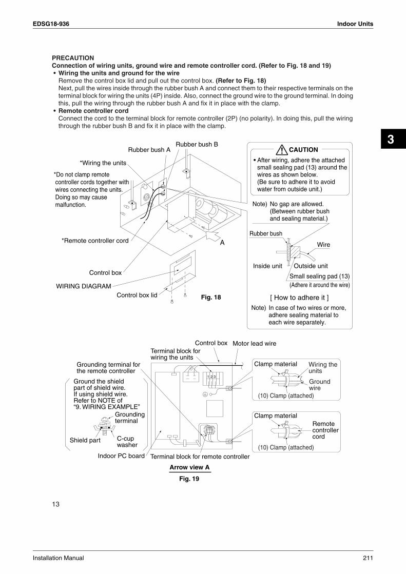
EDSG18-936 Indoor Units
3
PRECAUTIONConnection of wiring units, ground wire and remote controller cord. (Refer to Fig. 18 and 19)• Wiring the units and ground for the wire
Remove the control box lid and pull out the control box. (Refer to Fig. 18)Next, pull the wires inside through the rubber bush A and connect them to their respective terminals on the terminal block for wiring the units (4P) inside. Also, connect the ground wire to the ground terminal. In doing this, pull the wiring through the rubber bush A and fix it in place with the clamp.
• Remote controller cordConnect the cord to the terminal block for remote controller (2P) (no polarity). In doing this, pull the wiring through the rubber bush B and fix it in place with the clamp.
A
Rubber bush BRubber bush A
*Wiring the units
*Do not clamp remote controller cords together with wires connecting the units. Doing so may cause malfunction.
*Remote controller cord
Control box
Control box lidWIRING DIAGRAM
Fig. 18
CAUTION
• After wiring, adhere the attached small sealing pad (13) around the wires as shown below.(Be sure to adhere it to avoid water from outside unit.)
Rubber bush
Note) No gap are allowed.(Between rubber bush and sealing material.)
Note) In case of two wires or more, adhere sealing material to each wire separately.
Inside unit Outside unit
Wire
[ How to adhere it ]
Small sealing pad (13)(Adhere it around the wire)
Motor lead wire Control boxTerminal block for wiring the units
Terminal block for remote controllerIndoor PC board
Shield part C-cup washer
Ground the shieldpart of shield wire.If using shield wire.Refer to NOTE of“9. WIRING EXAMPLE”
Grounding terminal forthe remote controller
Groundingterminal
Arrow view A
Fig. 19
1 2 3
P1 P2
Remote controller cord
Clamp material Wiring the units
Ground wire
(10) Clamp (attached)
Clamp material
(10) Clamp (attached)
13
Installation Manual 211

Indoor Units EDSG18-936
Observe the notes mentioned below when wiring to the terminal block for wiring the units.
CAUTION• When clamping wiring, use the included clamping material to prevent outside pressure being exerted on
the wiring connections and clamp firmly. When doing the wiring, make sure the wiring is neat and does not cause the control box lid to stick up, then close the cover firmly.
• When attaching the control box lid, make sure you do not pinch any wires.• After all the wiring connections are done, fill in any gaps in the through holes with putty or insulation (pro-
cured locally) to prevent small animals and insects from entering the unit from outside. (If any do get in, they could cause short circuits in the control box.)
• Outside the machine, separate the weak wiring (remote controller cord) and strong wiring (interunit, ground, and other power wiring) at least 50 mm so that they do not pass through the same place together.Proximity may cause electrical interference, malfunctions, and breakage.
• Do not connect wires of different gauge to the same power supply terminal. (Looseness in the connection may cause overheating.) (Refer to Fig. 20)
• Observe the notes when wiring to the terminal block for wiring the units.(Use a round crimp-style terminal with insulation sleeve for connection to the terminal block for wiring the units. In case it cannot be used due to unavoidable reasons, connect wires of the same gauge to the both side as shown in Fig. 20.)
Follow the instructions below if the wiring gets very hot due to slack in the power wiring.• In wiring, make certain that prescribed wires are used, carry out complete connections, and fix the wires so
that outside forces are not applied to the terminals.• Use the correct screwdriver for tightening the terminal screws. If the blade of screwdriver is too small, the
head of the screw might be damaged, and the screw will not be properly tightened.• If the terminal screw are tightened too hard, screws might be damaged.• Refer to the table below for the tightening torque of the terminal screws.
Tightening torque (N • m)
Terminal block for remote controller 0.79 to 0.97
Terminal block for wiring the units 1.18 to 1.44
Ground terminal 1.44 to 1.94
Connect wires of the same gauge to both side. (GOOD)
Do not connect wires of the same gauge to one side. (WRONG)
Do not connect wires of different gauges. (WRONG)
Fig. 20
Round crimp-style terminal
Electric wireAttach insulation sleeve
14
212 Installation Manual

EDSG18-936 Indoor Units
3
9. WIRING EXAMPLEFor the wiring of outdoor unit and BP unit, refer to the installation manuals attached to the outdoor unit and BP unit.Confirm the system type.• 1 remote controller control: 1 remote controller controls 1 indoor unit (standard system). (Refer to Fig. 21)• Group control: 1 remote controller controls up to 16 indoor units.
(All indoor units operate according to the remote controller.) (Refer to Fig. 22)• 2 remote controllers control: 2 remote controllers control 1 indoor unit. (Refer to Fig. 23)
NOTE1. All transmission wiring except for the remote controller wires is polarized and must match the terminal
symbol.2. In case a shielding wire is to be used, connect a shielded portion with the grounding terminal for remote
controller inside the control box. (Also, connect the ground for the remote control to a grounded metal part.)3. For group control remote controller, choose the remote controller that suits the indoor unit which has the
most functions (as attached swing flap)
BP unit
Indoor unit
Remote controller (Optional accessories)
(NOTE.2)
1 2
P1P2
P1P2
3
1 2 3
1 remote controller control
Fig. 21
1 2
P1P2
P1P2
3
1 2 3
1 2
P1P2
3
1 2 3
1 2
P1P2
3
1 2 3
BP unit BP unit BP unit
Indoor unit Indoor unit Indoor unit
Group control
Remote controller (Optional accessories)
(NOTE.2)
(NOTE.2) (NOTE.2) (NOTE.2)
(NOTE.2)
Fig. 22
1 2
P1P2
P1P2P1P2
3
1 2 3
Remote controller (Optional accessories)
Indoor unit
(NOTE.2) (NOTE.2)
BP unit
2 remote controllers control
Fig. 23
15
Installation Manual 213

Indoor Units EDSG18-936
10. FIELD SETTING<Field setting must be made from the remote controller in accordance with the installation condi-tion.>• Setting can be made by changing the “Mode No.”, “FIRST CODE NO.” and “SECOND CODE NO.”.• For setting procedures and instructions, refer to the “FIELD SETTING” in the installation manual of the
remote controller.
1. Setting external static pressure• Change the SECOND CODE No. according to Table 3 depending on the resistance of the connecting duct.
(SECOND CODE NO. is factory set to “01” normal.)
Table 3
2. Setting with installing optional accessories• Refer to the installation manual of the optional accessories for the optional accessories installation.
3. Setting air filter sign• Remote controllers are equipped with liquid crystal display air filer signs to display the time to clean air
filters.• Change the SECOND CODE No. according to Table 4 depending on the amount of dirt or dust in the room.
(SECOND CODE NO. is factory set to “01” for filter contamination-light)
Table 4
4. When implementing group control• When using as a pair unit or as a parent unit for simultaneous operation multi, you may simultaneous
start/stop (group) control up to 16 unit with the remote controller.• In this case, all the indoor units in the group will operate in accordance with the group control remote
controller.• Select a remote controller which matches as many of the functions (swing flap, etc) in the group as
possible.
Wiring Method(1)Remove the control box lids. (See ‘‘8. ELECTRIC WIRING WORK’’.)(2)Cross-wire the terminal block for remote controller (P1 P2) inside the control box. (There is no
polarity.) (Refer to Fig. 22 on page 15 and Table 2 on page 12)
External static pressure Mode No. FIRST CODE NO. FIRST CODE NO.
Normal: 49Pa (5 mmH2O)
13 (23) 6
01
High static pressure:88/108Pa (9/11 mmH2O)
02
Low static pressure: 20Pa(2 mmH2O)
03
SettingSpacing time of display air filter
sign (long life type) Mode No.FIRST CODE
NO.SECOND
CODE NO.
Air filter contamination-light
Approx. 2500 hrs10 (20) 0
01
Air filter contamination-heavy
Approx. 1250 hrs 02
Indoor unit 1 Indoor unit 2
Group control remote control
Indoor unit 3
Fig. 24
16
214 Installation Manual

EDSG18-936 Indoor Units
3
5. Control by 2 remote controllers (Controlling 1 indoor unit by 2 remote controllers)• When using 2 remote controllers, one must be set to “MAIN” and the other to “SUB”.
MAIN/SUB CHANGEOVER(1)Insert a screwdriver into the recess between the upper and lower part of remote controller and,
working from the 2 positions, pry off the upper part. (The remote controller PC board is attached tothe upper part of remote controller.) (Refer to Fig. 25)
(2)Turn the MAIN/SUB changeover switch on one of the two remote controller PC board to “S”.(Leave the switch of the other remote controller set to “M”.) (Refer to Fig. 26)
Wiring Method (See ‘‘8. ELECTRIC WIRING WORK’’ on page 12)(3)Remove the control box lids.(4)Add remote control 2 (slave) to the terminal block for remote controller (P1, P2) in the control
box. (There is no polarity.) (Refer to Fig. 23 on page 15 and Table 2 on page 12)
11. INSTALLATION OF THE DECORATION PANEL Refer to the installation manual attached to the decoration panel.After installing the decoration panel, ensure that there is no space between the unit body and decoration panel.
12. TEST OPERATIONRefer to the section of “FOR THE FOLLOWING ITEMS, TAKE SPECIAL CARE DURING CON-STRUCTION AND CHECK AFTER INSTALLATION IS FINISHED” . • After finishing the construction of refrigerant piping, drain piping, and electric wiring, conduct test operation
accordingly to protect the unit.
1. How to test operation1. Open the gas side stop valve.2. Open the liquid side stop valve.3. Electrify crank case heater for 6 hours (Not required in case of a unit exclusively designed for cooling
only).4. Set to cooling operation with the remote controller and start operation by pushing ON/OFF button ( ).5. Press INSPECTION/TEST OPERATION button ( ) 4 times (2 times for wireless remote control-
ler) and operate at Test Operation mode for 3 minutes.6. Press INSPECTION/TEST OPERATION button ( ) and operate normally.7. Confirm function of unit according to the operation manual.
TEST
TEST
Upper part of remote controller
Insert the screwdriver here and gently work off the upper part of remote controller.
Lower part of remote
controller
Fig. 25
S
MS
SM
(Only one remote controller needs to be changed if factory settings have remained untouched.)
(Factory setting)Remote controller PC board
Fig. 26
17
Installation Manual 215

Indoor Units EDSG18-936
PRECAUTIONS• Refer to the diagnoses below if the unit does not operate properly.• After completing the test run, press the INSPECTION/TEST OPERATION button once to put the
unit in inspection mode, and make sure the Malfunction code is “00” (=normal).If the code reads anything other than “00”, refer to the malfunction diagnoses below.
NOTE• If a malfunction is preventing operation, refer to the malfunction diagnoses below.
2. Cautions for servicingWith the power on. Troubles can be monitored on the remote controller.• If the air conditioner does not operate normally after installing the air conditioner.
a malfunction shown in the table below may happened.
∗After turning on the power, the maximum is 90 seconds, although it will only display “88”. This is nota problem, and it will be set for 90 seconds.
Trouble shooting with the display on the liquid crystal display remote controller.With the wired remote controller. (NOTE 1) When the operation stops due to trouble, operation lamp flashed, and “ ” and the Malfunction code are indicated on the liquid crystal display. In such a case, diagnose the fault contents by refer-ing to the table on the Malfunction code list it case of group control, the unit No. is displayed so that the indoor unit no with the trouble can be recognized. (NOTE 2)
NOTE1. In case wired remote controller. Press the INSPECTION /TEST OPERATION button on remote con-
troller, “ ” starts flashing and changes the inspection mode.2. Keep down the ON/OFF button for 5 seconds or longer in the inspection mode and the above trouble
history disappears, after the Malfunction code goes on and off twice, followed by the code “00”(nor-mal). The display changes from the inspection mode to the normal mode.
3. Malfunction code• For places where the Malfunction code is left blank, the “ ” indication is not displayed. Though the
system continues operating, be sure to inspect the system and make repairs as necessary.• Depending on the type of indoor or outdoor unit, the Malfunction code may or may not be displayed.
Remote control display Malfunction
No display
• Power supply trouble or Open phase connection• Wrong wiring between indoor and outdoor unit• Indoor PC board faulty• Wrong remote control connection wiring• Remote control faulty• Fuse faulty
88∗ • Indoor PC board faulty• Wrong wiring between indoor and outdoor unit
88 flashing • Wrong wiring between indoor and outdoor unit
Code Malfunction/Remarks
A1 Indoor unit’s PC board faulty
A3 Drain water level abnormal
A6 Indoor fan motor overloaded, overcurrent or locked
A7Swing flap motor locked
Only the air flow direction can not be controlled.
AF Humidifier faulty
AHAir cleaner faulty
Only the air cleaner does not function.
18
216 Installation Manual

EDSG18-936 Indoor Units
3
AJType set improper
Capacity data is wrongly preset. Or there is nothing programmed in the data hold IC.
C4 Sensor (R2T) for heat exchanger temperature is fault
C5 Sensor (R3T) for heat exchanger temperature is fault
C9 Sensor for suction air temperature is fault
CJSensor for remote controller is fault
The remote controller thermistor does not function, but the system thermo run is possible.
E0 Action of safety device (outdoor unit)
E1 Outdoor unit’s PC board faulty (outdoor unit)
E3 High pressure abnormal (outdoor unit)
E4 Low pressure abnormal (outdoor unit)
E5 Compressor motor lock malfunction (outdoor unit)
E7 Outdoor fan motor lock malfunctionOutdoor fan instantaneous overcurrent malfunction (outdoor unit)
E9 Electronic expansion valve faulty (outdoor unit)
F3 Discharge pipe temperature abnormal (outdoor unit)
H3 High pressure switch faulty (outdoor unit)
H4 Low pressure switch faulty (outdoor unit)
H7 Outdoor motor position signal malfunction (outdoor unit)
H9 Outdoor air thermistor faulty (outdoor unit)
J3 Discharge pipe thermistor faulty (outdoor unit)
J5 Suction pipe thermistor faulty (outdoor unit)
J6 Heat exchanger thermistor faulty (outdoor unit)
L4Overheated heat-radiating fin (outdoor unit)
Inverter cooling defect.
L5Instantaneous overcurrent (outdoor unit)
Possible earth fault or short circuit in the compressor motor.
L8Electric thermal (outdoor unit)
Possible electrical overload in the compressor or cut line in the compressor motor.
L9Stall prevention (outdoor unit)
Compressor possibly locked.
LC Transmission malfunction between the outdoor control units’ inverters (outdoor unit)
P1 Open-phase (outdoor unit)
P3 PC board temperature sensor malfunction (outdoor unit)
P4 Heat-radiating fin temperature sensor malfunction (outdoor unit)
PJType set improper (outdoor unit)
Capacity data is wrongly preset. Or there is nothing programmed in the data hold IC.
U0 Suction pipe temperature abnormal
U1Reverse phase
Reverse two of the L1, L2 and L3 leads.
U2Power source voltage malfunction (outdoor unit)
Includes the defect in K1M.
19
Installation Manual 217

Indoor Units EDSG18-936
U4UF
Transmission error (indoor unit – outdoor unit)
Wrong wiring between indoor and outdoor units or malfunction of the PC board mounted on the indoor and the outdoor units.If UF is shown, the wiring between the indoor and outdoor units is not properly wired. Therefore, immediately disconnect the power supply and correct the wiring. (The com-pressor and the fan mounted on the outdoor unit may start operation independent of the remote controller operation.)
U5Transmission error (indoor unit – remote controller)
Transmission is improper between the indoor unit and the remote controller.
U8 Malfunction in transmission between main and sub remote controls. (Malfunction in sub remote control.)
UAMiss setting for multi system
Setting is wrong for selector switch of multi-system. (see switch SS2 on the main unit’s PC board)
UC Central control address overlapping
20
3P156215-4C
218 Installation Manual

EDSG18-936
Operation Manual 219
4
Part 4Operation Manual
1. Operations...........................................................................................2201.1 RMKS112/140/160E Series .................................................................2201.2 FTKS, FDKS Series .............................................................................2211.3 FFQ25/35/50/60B Series......................................................................2751.4 FCQ35/50/60/71B Series .....................................................................2881.5 FBQ60/71B Series ...............................................................................299

Operations EDSG18-936
1. Operations1.1 RMKS112/140/160E Series
REGARDING USESuper Multi Plus System air conditioner
POINTS THE CUSTOMER SHOULD BE AWARE OFCOMFORTAt startup• After the power is initially turned on, it will take approx. 10 minutes until startup. Usually the unit will start
in 3 minutes.
Heating operation (Not for a unit for cooling only)• The colder it is outside or the greater the number of indoor units, the longer the time required from the
start of operation until the emission of warm air (around 35°C). When the outside temperature is -5 to 2°C, the inside temperature is 5 to 10°C, and total indoor unit combination is 100% capacity, the first star-tup of all indoor units in the morning will take approximately 20 to 30 minutes.
• Oil return operation will be performed once every 8 hours to preserve the lubrication of oil to the com-pressor.Since operation is switched to cooling cycle during heating operation in order to return the oil, heating operation will not be possible for around 5 to 10 minutes.
• When the outside temperature is 28°C or higher, the unit will be set to the standby mode for protection.
OPERATING NOISEAt startup• During startup, in order to emit warm or cool air as quickly as possible, the sound of refrigerant flowing
will be heard for a short time (1 to 2 minutes) from the outdoor unit.
At shutdown• In order to ensure smooth startup the next time this unit is operated, the outdoor unit will continue to oper-
ate for around 1 minutes after shutdown. (The time of continued operation depends on the outside tem-perature, capacity of connected indoor units, and connection pipe length.)
Cooling at low outside temperatures• During cooling operation when the outside temperature is 20°C or less, the fan of the outdoor unit will
operate at low speed to preserve capacity and the outdoor unit valve will be opened depending on the pressure conditions, making it more likely that the sound of refrigerant flowing will be heard.
Defrost (Not for a unit for cooling only)• When the outside unit is performing defrosting operation, the fan of the indoor unit will stop temporarily,
and the slight sound of refrigerant flowing will be heard.
Excessive heating load (Not for a unit for cooling only)• During heating operation when the outside temperature is high (15 to 24°C), the fan of the outdoor unit
will be operated at low speed, making it more likely that the sound of refrigerant flowing will be heard from the outdoor unit.
3PN07192-3
220 Operation Manual

EDSG18-936 Operations
4
1.2 FTKS, FDKS Series1.2.1 Manual Contents and Reference Page
: Illustrations are for wall mounted type FTKS50/60/71F as representative.
Model SeriesWall Mounted Type Duct Connected Type
FTKS25/35D FTKS50/60/71 FTKS50B FDKS25/35CA FDKS50/60CFDKS25/35EA
Read before Operation
Safety Precautions 222 222 222 222 222
Names of Parts 224 227 230 233 233
Preparation before Operation 236 236 236 236 236
Operation
DRY, COOL, FAN Operation 239 239 239 239 239
Adjusting the Airflow Direction 241 243 243 — —
POWERFUL Operation 245 245 245 245 245
OUTDOOR UNIT QUIET Operation 246 246 246 246 246
ECONO Operation 247 — — — —
MOLD PROOF Operation 248 — — — —
HOME LEAVE Operation — 249 249 249 249
INTELLIGENT EYE Operation 251 253 253 — —
TIMER Operation 255 255 255 255 255
Note for Multi System 257 257 257 257 257
Care
Care and Cleaning 259 262 265 268 270
Troubleshooting
Troubleshooting 272 272 272 272 272
Drawing No. 3P194550-4C 3P192025-1 3P098595-11P 3P196326-8C 3P196326-9C
Operation Manual 221

Operations EDSG18-936
1.2.2 Safety Precautions
Safety precautions• Keep this manual where the operator can easily find them.• Read this manual attentively before starting up the unit.• For safety reason the operator must read the following cautions carefully.• This manual classifies precautions into WARNING and CAUTION. Be sure to follow all precautions below: they are all
important for ensuring safety.
WARNING• In order to avoid fire, explosion or injury, do not operate the unit when harmful, among which flammable or
corrosive gases, are detected near the unit.• It is not good for health to expose your body to the air flow for a long time.• Do not put a finger, a rod or other objects into the air outlet or inlet. As the fan is rotating at a high speed, it will
cause injury.• Do not attempt to repair, relocate, modify or reinstall the air conditioner by yourself. Incorrect work will cause electric
shocks, fire etc. For repairs and reinstallation, consult your Daikin dealer for advice and information.
• The refrigerant used in the air conditioner is safe. Although leaks should not occur, if for some reason any refrigerant happens to leak into the room, make sure it does not come in contact with any flame as of gas heaters, kerosene heaters or gas range.
• If the air conditioner is not cooling (heating) properly, the refrigerant may be leaking, so call your dealer.When carrying out repairs accompanying adding refrigerant, check the content of the repairs with our service staff.
• Do not attempt to install the air conditioner by your self. Incorrect work will result in water leakage, electric shocks or fire. For installation, consult the dealer or a qualified technician.
• In order to avoid electric shock, fire or injury, if you detect any abnormally such as smell of fire, stop the operation and turn off the breaker. And call your dealer for instructions.
CAUTION• The air conditioner must be earthed. Incomplete earthing may result in electric shocks. Do not connect the
earth line to a gas pipe, water pipe, lightning rod, or a telephone earth line.
• In order to avoid any quality deterioration, do not use the unit for cooling precision instruments, food, plants, animals or works of art.
• Never expose little children, plants or animals directly to the air flow.• Do not place appliances which produce open fire in places exposed to the air flow from the unit or under the
indoor unit. It may cause incomplete combustion or deformation of the unit due to the heat.• Do not block air inlets nor outlets. Impaired air flow may result in insufficient performance or trouble.
WARNINGIf you do not follow these instructions exactly, the unit may cause property damage, personal injury or loss of life.
CAUTIONIf you do not follow these instructions exactly, the unit may cause minor or moderate property damage or personal injury.
Never do. Be sure to follow the instructions.
Be sure to earth the air conditioner.Never cause the air conditioner (including the remote controller) to get wet.
Never touch the air conditioner (including the remote controller) with a wet hand.
222 Operation Manual

EDSG18-936 Operations
4
• Do not stand or sit on the outdoor unit. Do not place any object on the unit to avoid injury, do not remove the fan guard.• Do not place anything under the indoor or outdoor unit that must be kept away from moisture. In certain conditions,
moisture in the air may condense and drip.• After a long use, check the unit stand and fittings for damage.• Do not touch the air inlet and aluminum fins of outdoor unit. It may cause injury.• The appliance is not intended for use by young children or infirm persons without supervision.• Young children should be supervised to ensure that they do not play with the appliance.
• To avoid oxygen deficiency, ventilate the room sufficiently if equipment with burner is used together with the air conditioner.
• Before cleaning, be sure to stop the operation, turn the breaker off or pull out the supply cord.• Do not connect the air conditioner to a power supply different from the one as specified. It may cause trou-
ble or fire.• Depending on the environment, an earth leakage breaker must be installed. Lack of an earth leakage breaker may
result in electric shocks.• Arrange the drain hose to ensure smooth drainage. Incomplete draining may cause wetting of the building, furniture
etc.• Do not place objects in direct proximity of the outdoor unit and do not let leaves and other debris accumulate around
the unit.Leaves are a hotbed for small animals which can enter the unit. Once in the unit, such animals can cause malfunc-tions, smoke or fire when making contact with electrical parts.
• Do not operate the air conditioner with wet hands.
• Do not wash the indoor unit with excessive water, only use a slightly wet cloth.• Do not place things such as vessels containing water or anything else on top of the unit. Water may pene-
trate into the unit and degrade electrical insulations, resulting in an electric shock.
To install the air conditioner in the following types of environments, consult the dealer.• Places with an oily ambient or where steam or soot occurs.• Salty environment such as coastal areas.• Places where sulfide gas occurs such as hot springs.• Places where snow may block the outdoor unit.
The drain from the outdoor unit must be discharged to a place of good drainage.
For installation, choose a place as described below.• A place solid enough to bear the weight of the unit which does not amplify the operation noise or vibration.• A place from where the air discharged from the outdoor unit or the operation noise will not annoy
your neighbours.
• For power supply, be sure to use a separate power circuit dedicated to the air conditioner.
• Relocating the air conditioner requires specialized knowledge and skills. Please consult the dealer if reloca-tion is necessary for moving or remodeling.
Installation site.
Consider nuisance to your neighbours from noises.
Electrical work.
System relocation.
Operation Manual 223

Operations EDSG18-936
1.2.3 Names of Parts
FTKS25/35D
Names of parts
Indoor Unit
ON/OFF
16 14
13
15
12
1 3 4
5
7
91011
8
6
2
224 Operation Manual
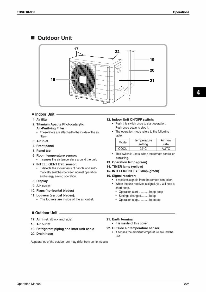
EDSG18-936 Operations
4
Outdoor Unit
Indoor Unit1. Air filter
2. Titanium Apatite Photocatalytic Air-Purifying Filter:• These filters are attached to the inside of the air
filters.
3. Air inlet
4. Front panel
5. Panel tab
6. Room temperature sensor:• It senses the air temperature around the unit.
7. INTELLIGENT EYE sensor:• It detects the movements of people and auto-
matically switches between normal operation and energy saving operation.
8. Display
9. Air outlet
10. Flaps (horizontal blades)
11. Louvers (vertical blades):• The louvers are inside of the air outlet.
12. Indoor Unit ON/OFF switch: • Push this switch once to start operation.
Push once again to stop it.• The operation mode refers to the following
table.
• This switch is useful when the remote controller is missing.
13. Operation lamp (green)14. TIMER lamp (yellow)15. INTELLIGENT EYE lamp (green)
16. Signal receiver:• It receives signals from the remote controller.• When the unit receives a signal, you will hear a
short beep.• Operation start .............beep-beep• Settings changed..........beep• Operation stop ..............beeeeep
Outdoor Unit
17. Air inlet: (Back and side)
18. Air outlet
19. Refrigerant piping and inter-unit cable
20. Drain hose
21. Earth terminal:• It is inside of this cover.
22. Outside air temperature sensor:• It senses the ambient temperature around the
unit.
Appearance of the outdoor unit may differ from some models.
19
22
20
2118
17
ModeTemperature
settingAir flow
rateCOOL 22°C AUTO
Operation Manual 225

Operations EDSG18-936
Remote Controller
1. Signal transmitter:• It sends signals to the indoor unit.
2. Display:• It displays the current settings.
(In this illustration, each section is shown with all its displays ON for the purpose of explanation.)
3. ECONO button:ECONO operation.
4. POWERFUL button:POWERFUL operation
5. TEMPERATURE adjustment buttons:• It changes the temperature setting.
6. ON/OFF button:• Press this button once to start operation.
Press once again to stop it.7. MODE selector button:
• It selects the operation mode.(DRY/COOL/FAN)
8. QUIET button: OUTDOOR UNIT QUIET operation.
9. FAN setting button:• It selects the air flow rate setting.
10. SWING button:• Adjusting the Air Flow Direction.
11. MOLD PROOF button:MOLD PROOF operation.
12. SENSOR button: INTELLIGENT EYE operation.
13. ON TIMER button14. OFF TIMER button15. TIMER Setting button:
• It changes the time setting.16. TIMER CANCEL button:
• It cancels the timer setting.17. CLOCK button18. RESET button:
• Restart the unit if it freezes.
TEMPON/OFF
POWERFUL
MODE FAN SWINGQUIET SENSOR
ECONO
MOLD PROOF
TIMER
ON CANCEL
OFF
1
2
5
6
910
12
11
16
1817
13
15
14
<ARC433B47>
3
4
7
8
226 Operation Manual
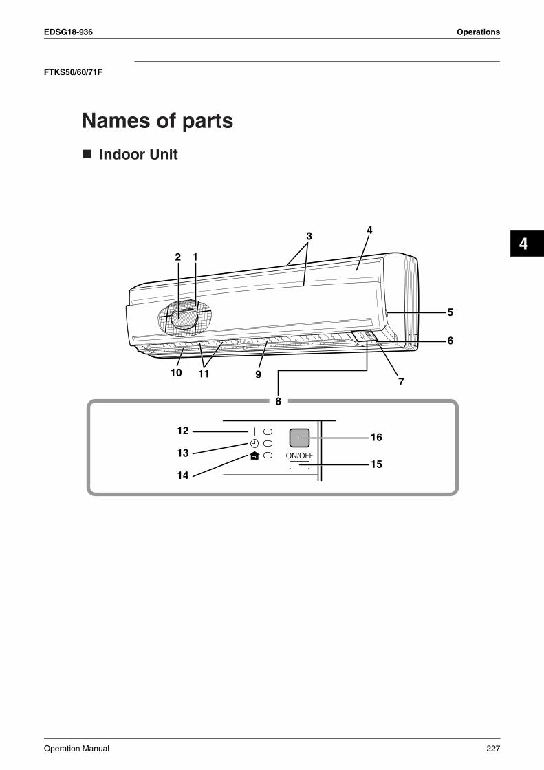
EDSG18-936 Operations
4
FTKS50/60/71F
Names of parts
Indoor Unit
12
43
10 11 97
8
15
12
13
14
16
6
5
Operation Manual 227

Operations EDSG18-936
Outdoor Unit
Indoor Unit1. Air filter
2. Titanium Apatite Photocatalytic Air-Purifying Filter
3. Air inlet
4. Front panel
5. Panel tab
6. INTELLIGENT EYE sensor:• It detects the movements of people and
automatically switches between normal operation and energy saving operation.
7. Room temperature sensor:• It senses the air temperature around the unit.
8. Display
9. Air outlet
10. Flap (horizontal blade):
11. Louvers (vertical blades):• The Louvers are inside of the air outlet.
12. Operation lamp (green)
13. TIMER lamp (yellow):
14. HOME LEAVE lamp (red):• Lights up when you use HOME LEAVE
Operation.
15. Indoor Unit ON/OFF switch:• Push this switch once to start operation.
Push once again to stop it.• The operation mode refer to the following table.
• This switch is useful when the remote controller is missing.
16. Signal receiver:• It receives signals from the remote controller.• When the unit receives a signal, you will hear a
short beep.• Operation start .............beep-beep• Settings changed..........beep• Operation stop ..............beeeeep
Outdoor Unit17. Air inlet: (Back and side)
18. Air outlet
19. Refrigerant piping and inter-unit cable
20. Drain hose
21. Earth terminal:• It is inside of this cover.
Appearance of the outdoor unit may differ from some models.
19
20
2118
17
ModeTemperature
settingAir flow rate
COOL 22°C AUTO
228 Operation Manual
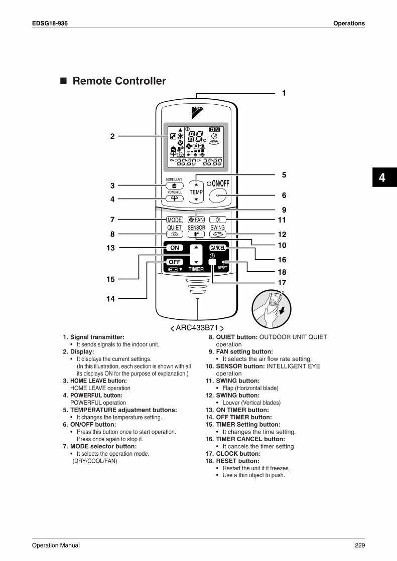
EDSG18-936 Operations
4
Remote Controller
1. Signal transmitter:• It sends signals to the indoor unit.
2. Display:• It displays the current settings.
(In this illustration, each section is shown with all its displays ON for the purpose of explanation.)
3. HOME LEAVE button: HOME LEAVE operation
4. POWERFUL button: POWERFUL operation
5. TEMPERATURE adjustment buttons:• It changes the temperature setting.
6. ON/OFF button:• Press this button once to start operation.
Press once again to stop it.7. MODE selector button:
• It selects the operation mode.(DRY/COOL/FAN)
8. QUIET button: OUTDOOR UNIT QUIET operation
9. FAN setting button:• It selects the air flow rate setting.
10. SENSOR button: INTELLIGENT EYE operation
11. SWING button: • Flap (Horizontal blade)
12. SWING button: • Louver (Vertical blades)
13. ON TIMER button:14. OFF TIMER button:15. TIMER Setting button:
• It changes the time setting.16. TIMER CANCEL button:
• It cancels the timer setting.17. CLOCK button:18. RESET button:
• Restart the unit if it freezes.• Use a thin object to push.
TIMER
ON CANCEL
OFF
1
2
5
6
911
< ARC433B71 >
3
4
7
81012
16
181715
14
13
Operation Manual 229

Operations EDSG18-936
FTKS50B
Indoor Unit
Main unit control panel
7
14
11
12
13
43
1512
9 108 6
5
17
16
230 Operation Manual

EDSG18-936 Operations
4
Outdoor Unit
Indoor Unit1. Air filter
2. Air purifying filter with photocatalytic deodorizing function:• These filters are attached to the inside of the air
filters.
3. Air inlet
4. Front grille
5. Grille tab
6. INTELLIGENT EYE sensor:• It detects the movements of people and
automatically switches between normal operation and energy saving operation.
7. Display
8. Air outlet
9. Flap (horizontal blade)
10. Louvers (vertical blades):• The Louvers are inside of the air outlet.
11. Operation lamp (green)
12. TIMER lamp (yellow)
13. HOME LEAVE lamp (red):• Lights up when you use HOME LEAVE
Operation.
14. Indoor Unit ON/OFF switch:• Push this switch once to start operation.
Push once again to stop it.• The operation mode refer to the following table.
• This switch is useful when the remote controller is missing.
15. Packaging materials: 50 class only• If any packaging materials are included,
please remove before operating.
16. Room temperature sensor:• It senses the air temperature around the unit.
17. Signal receiver:• It receives signals from the remote controller.• When the unit receives a signal, you will hear a
short beep.• Operation start .............beep-beep• Settings changed..........beep• Operation stop ..............beeeeep
Outdoor Unit18. Air inlet: (Back and side)
19. Air outlet
20. Refrigerant piping and inter-unit cable
21. Drain hose
22. Earth terminal:• It is inside of this cover.
Appearance of the outdoor unit may differ from some models.
20
21
2219
18
ModeTemperature
settingAir flow
rateFTKS COOL 22˚C AUTOFTXS AUTO 25˚C AUTO
Operation Manual 231

Operations EDSG18-936
Remote Controller
1. Signal transmitter:• It sends signals to the indoor unit.
2. Display:• It displays the current settings.
(In this illustration, each section is shown with all its displays ON for the purpose of explanation.)
3. HOME LEAVE button: for HOME LEAVE operation
4. POWERFUL button: for POWERFUL operation
5. TEMPERATURE adjustment buttons:• It changes the temperature of time setting.
6. ON/OFF button:• Press this button once to start operation.
Press once again to stop it.
7. MODE selector button:• It selects the operation mode.(AUTO/DRY/COOL/HEAT/FAN)
8. SILENT button: for OUTDOOR UNIT SILENT operation
9. FAN setting button:• It selects the air flow rate setting.
10. SENSOR button: for INTELLIGENT EYE operation
11. SWING button: • Flap (Horizontal blade)
12. SWING button: • Louver (Vertical blades)
13. ON TIMER button
14. OFF TIMER button
15. TIMER Setting button:• It changes the time setting.
16. TIMER CANCEL button:• It cancels the timer setting.
17. CLOCK button
C
O N
TEMPON/OFF
POWERFUL
HOME LEAVE
MODE
TIMER
FANSILENT SWING
ON CANCEL
OFF
SENSOR
1
2
5
6
911
1012
16
17
13
15
14
< ARC433A21, A22 >
3
4
7
8
232 Operation Manual
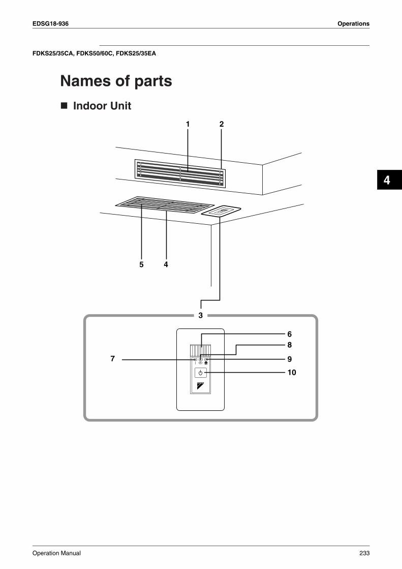
EDSG18-936 Operations
4
FDKS25/35CA, FDKS50/60C, FDKS25/35EA
Names of parts
Indoor Unit
3
68
9
10
7
1
45
2
Operation Manual 233

Operations EDSG18-936
Outdoor Unit
Indoor Unit1. Air outlet
2. Air outlet grille: (Field supply)• Appearance of the Air outlet grille and Air inlet
grille may differ with some models.
3. Display, Control panel
4. Suction grille: (Option)• Appearance of the suction grille and Air inlet
grille may differ with some models.
5. Air inlet
6. Room temperature sensor:• It senses the air temperature around the unit.
7. Operation lamp (green)
8. TIMER lamp (yellow)
9. HOME LEAVE lamp (red):• LIghts up when you use HOME LEAVE
operation.
10. Indoor Unit ON/OFF switch:• Push this switch once to start operation.
Push once again to stop it.• This switch is useful when the remote controller
is missing.
• The operation mode refers to the following table.
Outdoor Unit
11. Air inlet: (Back and side)
12. Refrigerant piping and inter-unit cable
13. Drain hose
14. Earth terminal:• It is inside of this cover.
15. Air outlet
Appearance of the outdoor unit may differ from some models.
12
13
14
15
11
ModeTemperature
settingAir flow
rateF(C)DKS COOL 22°C AUTOF(C)DXS AUTO 25°C AUTO
234 Operation Manual
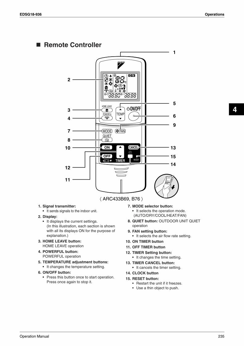
EDSG18-936 Operations
4
Remote Controller
1. Signal transmitter:• It sends signals to the indoor unit.
2. Display:• It displays the current settings.
(In this illustration, each section is shown with all its displays ON for the purpose of explanation.)
3. HOME LEAVE button: HOME LEAVE operation
4. POWERFUL button: POWERFUL operation
5. TEMPERATURE adjustment buttons:• It changes the temperature setting.
6. ON/OFF button:• Press this button once to start operation.
Press once again to stop it.
7. MODE selector button:• It selects the operation mode.(AUTO/DRY/COOL/HEAT/FAN)
8. QUIET button: OUTDOOR UNIT QUIET operation
9. FAN setting button:• It selects the air flow rate setting.
10. ON TIMER button11. OFF TIMER button12. TIMER Setting button:
• It changes the time setting.
13. TIMER CANCEL button:• It cancels the timer setting.
14. CLOCK button15. RESET button:
• Restart the unit if it freezes.• Use a thin object to push.
1
2
5
6
9
13
15
14
10
12
11
⟨ ARC433B69, B76 ⟩
3
4
7
8
Operation Manual 235

Operations EDSG18-936
1.2.4 Preparation before Operation
Preparation Before Operation
To set the batteries
1. Slide the front cover to take it off.
2. Set two dry batteries (AAA).
3. Set the front cover as before.
ATTENTIONAbout batteries• When replacing the batteries, use batteries of the same type, and replace the two old batteries
together.• When the system is not used for a long time, take the batteries out.• We recommend replacing once a year, although if the remote controller display begins to fade or if
reception deteriorates, please replace with new alkali batteries. Using manganese batteries reduces the lifespan.
• The attached batteries are provided for the initial use of the system.The usable period of the batteries may be short depending on the manufactured date of the air conditioner.
+–
–+
2
3
1
Position and – correctly!
+
236 Operation Manual
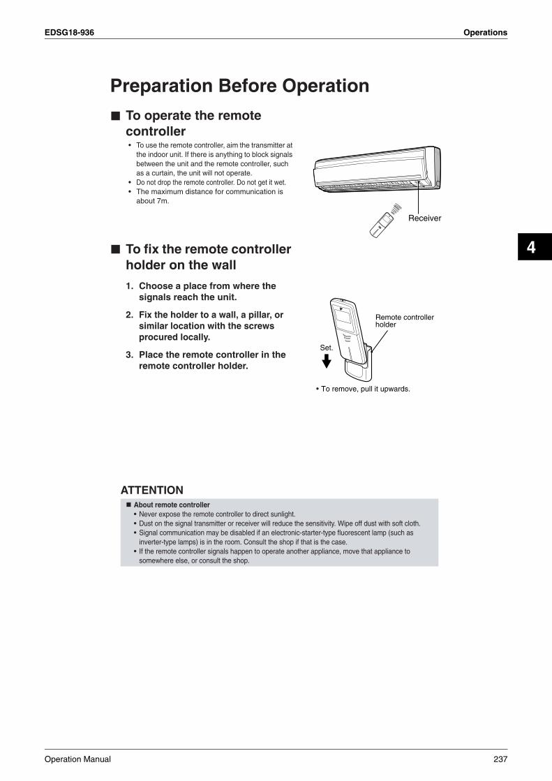
EDSG18-936 Operations
4
Preparation Before Operation
To operate the remote controller• To use the remote controller, aim the transmitter at
the indoor unit. If there is anything to block signals between the unit and the remote controller, such as a curtain, the unit will not operate.
• Do not drop the remote controller. Do not get it wet.• The maximum distance for communication is
about 7m.
To fix the remote controller holder on the wall
1. Choose a place from where the signals reach the unit.
2. Fix the holder to a wall, a pillar, or similar location with the screws procured locally.
3. Place the remote controller in the remote controller holder.
ATTENTIONAbout remote controller• Never expose the remote controller to direct sunlight.• Dust on the signal transmitter or receiver will reduce the sensitivity. Wipe off dust with soft cloth.• Signal communication may be disabled if an electronic-starter-type fluorescent lamp (such as
inverter-type lamps) is in the room. Consult the shop if that is the case.• If the remote controller signals happen to operate another appliance, move that appliance to
somewhere else, or consult the shop.
Receiver
Remote controller holder
Set.
To remove, pull it upwards.•
Operation Manual 237

Operations EDSG18-936
To set the clock
1. Press “CLOCK button”.
is displayed.
blinks.
2. Press “TIMER setting button” to set the clock to the present time.
Holding down “ ” or “ ” button rapidly increases or decreases the time display.
3. Press “CLOCK button”.
blinks.
Turn the breaker ON• Turning ON the breaker opens the flap, then
closes it again. (This is a normal procedure.)
NOTETips for saving energy• Be careful not to cool the room too much.
Keeping the temperature setting at a moderate level helps save energy.• Cover windows with a blind or a curtain.
Blocking sunlight and air from outdoors increases the cooling effect.• Clogged air filters cause inefficient operation and waste energy. Clean them
once in about every two weeks.Please note• The air conditioner always consumes 15-35 watts of electricity even while it is not operating.• If you are not going to use the air conditioner for a long period, for example in spring or autumn, turn the breaker OFF.• Use the air conditioner in the following conditions.
• Operation outside this humidity or temperature range may cause a safety device to disable the system.
TIMER
ON CANCEL
OFF1, 3
2
Recommended temperature setting
For cooling:26°C – 28°C
Mode Operating conditions If operation is continued out of this range
COOL Outdoor temperature: <3MKS50/4MKS71> –10 to 46˚C<4MKS80> 10 to 46˚C<RKS> –10 to 46˚C
Indoor temperature: 18 to 32˚CIndoor humidity: 80% max.
• A safety device may work to stop the operation.(In multi system, it may work to stop the operation of the outdoor unit only.)
• Condensation may occur on the indoor unit and drip.
DRY Outdoor temperature:<3MKS50/4MKS71> –10 to 46˚C<4MKS80> 10 to 46˚C<RKS> –10 to 46˚C
Indoor temperature: 18 to 32˚CIndoor humidity: 80% max.
• A safety device may work to stop the operation.• Condensation may occur on the indoor unit and drip.
238 Operation Manual
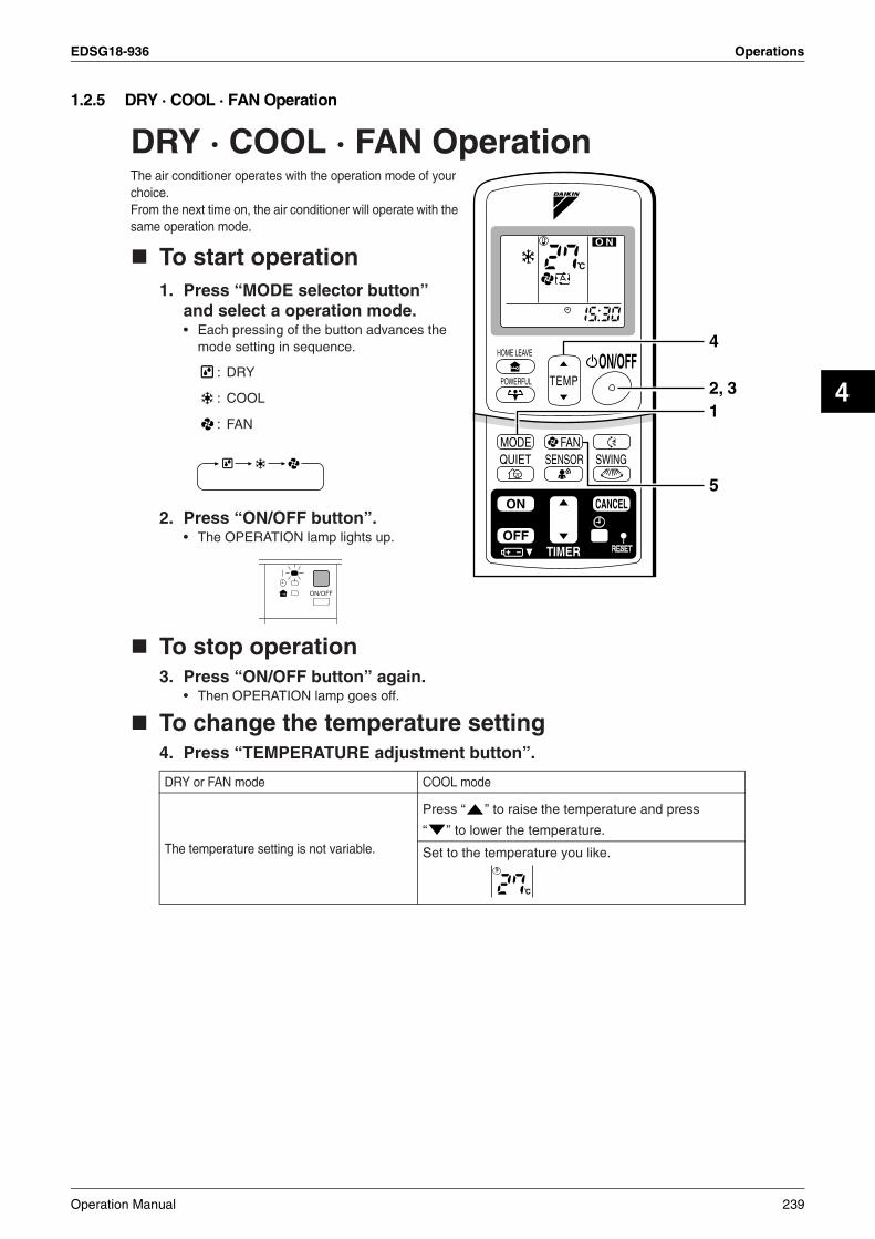
EDSG18-936 Operations
4
1.2.5 DRY · COOL · FAN Operation
DRY · COOL · FAN OperationThe air conditioner operates with the operation mode of your choice.From the next time on, the air conditioner will operate with the same operation mode.
To start operation1. Press “MODE selector button”
and select a operation mode.• Each pressing of the button advances the
mode setting in sequence.
: DRY
: COOL
: FAN
2. Press “ON/OFF button”.• The OPERATION lamp lights up.
To stop operation3. Press “ON/OFF button” again.
• Then OPERATION lamp goes off.
To change the temperature setting4. Press “TEMPERATURE adjustment button”.
DRY or FAN mode COOL mode
The temperature setting is not variable.
Press “ ” to raise the temperature and press
“ ” to lower the temperature.
Set to the temperature you like.
TIMER
ON CANCEL
OFF
2, 31
4
5
Operation Manual 239
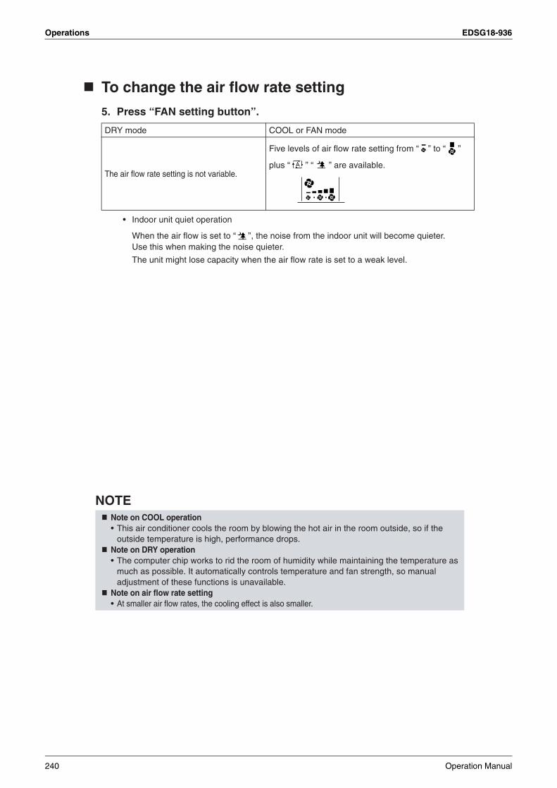
Operations EDSG18-936
To change the air flow rate setting
5. Press “FAN setting button”.
• Indoor unit quiet operation
When the air flow is set to “ ”, the noise from the indoor unit will become quieter. Use this when making the noise quieter.
The unit might lose capacity when the air flow rate is set to a weak level.
NOTE
DRY mode COOL or FAN mode
The air flow rate setting is not variable.
Five levels of air flow rate setting from “ ” to “ ”
plus “ ” “ ” are available.
Note on COOL operation• This air conditioner cools the room by blowing the hot air in the room outside, so if the
outside temperature is high, performance drops.Note on DRY operation• The computer chip works to rid the room of humidity while maintaining the temperature as
much as possible. It automatically controls temperature and fan strength, so manual adjustment of these functions is unavailable.
Note on air flow rate setting• At smaller air flow rates, the cooling effect is also smaller.
240 Operation Manual

EDSG18-936 Operations
4
1.2.6 Adjusting the Airflow Direction
FTKS25/35D
Adjusting the Air Flow DirectionYou can adjust the air flow direction to increase your com-fort.
To adjust the horizontal blades (flaps)
1. Press “SWING button”.
is displayed on the LCD and the flaps will begin to swing.
2. When the flaps have reached the desired position, press “SWING button” once more.The display will go blank.The flaps will stop moving.
TEMPON/OFF
POWERFUL
MODE FAN SWINGQUIET SENSOR
ECONO
MOLD PROOF
TIMER
ON CANCEL
OFF
1, 2
Operation Manual 241

Operations EDSG18-936
To adjust the vertical blades (louvers)
Hold the knob and move the louvers.(You will find a knob on the left-side and the right-side blades.)
• When the unit is installed in the corner of a room, the direction of the louvers should be facing away from the wall.If they face the wall, the wall will block off the wind, causing the cooling efficiency to drop.
Notes on flaps and louvers angles• When “SWING button” is selected, the
flaps swinging range depends on the operation mode. (See the figure.)
• If the unit is operated after being stopped with the flaps pointed down in cooling or dry operation, the flaps will automatically move to a horizontal position after about one hour to prevent condensation from forming on them.
ATTENTION• Always use a remote controller to adjust the
flaps angle. If you attempt to move it forcibly with hand when it is swinging, the mechanism may be broken.
• Be careful when adjusting the louvers. Inside the air outlet, a fan is rotating at a high speed.
5˚
In DRY mode or COOL mode
When stop operation
Upper limit
Lower limit
10˚
50˚
In FAN mode
70˚
When stop operationUpper limit
Lower limit
242 Operation Manual

EDSG18-936 Operations
4
FTKS50/60/71F, FTKS50B
12
Adjusting the Air Flow DirectionYou can adjust the air flow direction to increase your comfort.
To adjust the horizontal blade (flap)
1. Press “SWING button ”.• “ ” is displayed on the LCD and the
flaps will begin to swing.
2. When the flap has reached the desired position, press “SWING button ” once more.• The flap will stop moving.
• “ ” disappears from the LCD.
To adjust the vertical blades (louvers)
3. Press “SWING button ”.• “ ” is displayed on the LCD.
4. When the louvers have reached the desired position, press the “SWING button ” once more.• The louvers will stop moving.• “ ” disappears from the LCD.
TIMER
ON CANCEL
OFF
1, 2
3, 4
Operation Manual 243
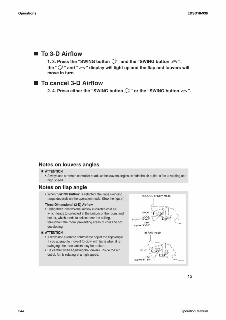
Operations EDSG18-936
13
To 3-D Airflow1. 3. Press the “SWING button ” and the “SWING button ”:the “ ” and “ ” display will light up and the flap and louvers will move in turn.
To cancel 3-D Airflow2. 4. Press either the “SWING button ” or the “SWING button ”.
Notes on louvers angles
Notes on flap angle
ATTENTION• Always use a remote controller to adjust the louvers angles. In side the air outlet, a fan is rotating at a
high speed.
• When “SWING button” is selected, the flaps swinging range depends on the operation mode. (See the figure.)
Three-Dimensional (3-D) Airflow• Using three-dimensional airflow circulates cold air,
which tends to collected at the bottom of the room, and hot air, which tends to collect near the ceiling, throughout the room, preventing areas of cold and hot developing.
ATTENTION• Always use a remote controller to adjust the flaps angle.
If you attempt to move it forcibly with hand when it is swinging, the mechanism may be broken.
• Be careful when adjusting the louvers. Inside the air outlet, fan is rotating at a high speed.
STOP
COOLapprox. 10°~40°
DRYapprox. 5°~35°
In COOL or DRY mode
STOP
In FAN mode
FANapprox. 5°~55°
244 Operation Manual
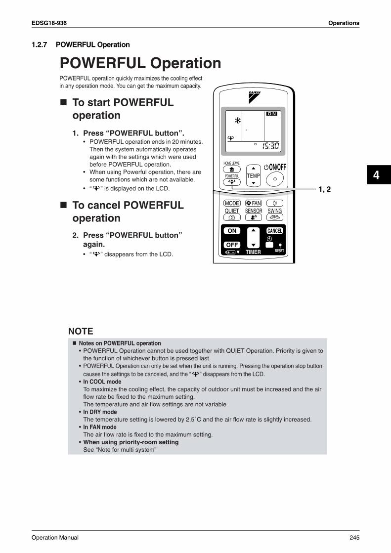
EDSG18-936 Operations
4
1.2.7 POWERFUL Operation
POWERFUL OperationPOWERFUL operation quickly maximizes the cooling effect in any operation mode. You can get the maximum capacity.
To start POWERFUL operation
1. Press “POWERFUL button”.• POWERFUL operation ends in 20 minutes.
Then the system automatically operates again with the settings which were used before POWERFUL operation.
• When using Powerful operation, there are some functions which are not available.
• “ ” is displayed on the LCD.
To cancel POWERFUL operation
2. Press “POWERFUL button” again.• “ ” disappears from the LCD.
NOTENotes on POWERFUL operation• POWERFUL Operation cannot be used together with QUIET Operation. Priority is given to
the function of whichever button is pressed last.• POWERFUL Operation can only be set when the unit is running. Pressing the operation stop button
causes the settings to be canceled, and the “ ” disappears from the LCD.• In COOL mode
To maximize the cooling effect, the capacity of outdoor unit must be increased and the air flow rate be fixed to the maximum setting.The temperature and air flow settings are not variable.
• In DRY modeThe temperature setting is lowered by 2.5˚C and the air flow rate is slightly increased.
• In FAN modeThe air flow rate is fixed to the maximum setting.
• When using priority-room settingSee “Note for multi system”
TIMER
ON CANCEL
OFF
1, 2
Operation Manual 245

Operations EDSG18-936
1.2.8 OUTDOOR UNIT QUIET Operation
OUTDOOR UNIT QUIET OperationOUTDOOR UNIT QUIET operation lowers the noise level of the outdoor unit by changing the frequency and fan speed on the outdoor unit. This function is convenient during night.
To start OUTDOOR UNIT QUIET operation
1. Press “QUIET button”.• “ ” is displayed on the LCD.
To cancel OUTDOOR UNIT QUIET operation
2. Press “QUIET button” again.• “ ” disappears from the LCD.
NOTENote on OUTDOOR UNIT QUIET operation• If using a multi system, this function will work only when the OUTDOOR UNIT QUIET
operation is set on all operated indoor units.However, if using priority-room setting, see “Note for multi system”.
• This function is available in COOL mode.(This is not available in FAN and DRY mode.)
• POWERFUL operation and OUTDOOR UNIT QUIET operation cannot be used at the same time.Priority is given to the function of whichever button is pressed last.
• If operation is stopped using the remote controller or the main unit ON/OFF switch when using OUTDOOR UNIT QUIET operation, “ ” will remain on the remote controller display.
TIMER
ON CANCEL
OFF
1, 2
246 Operation Manual
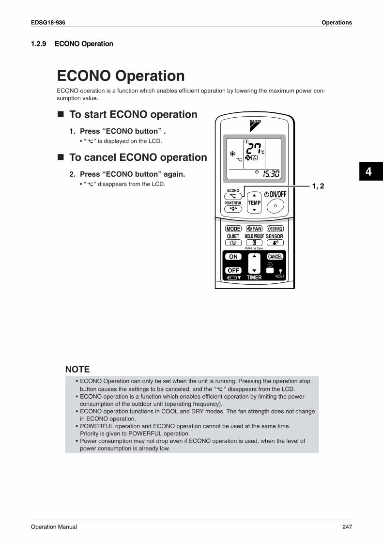
EDSG18-936 Operations
4
1.2.9 ECONO Operation
ECONO OperationECONO operation is a function which enables efficient operation by lowering the maximum power con-sumption value.
To start ECONO operation
1. Press “ECONO button” .• “ ” is displayed on the LCD.
To cancel ECONO operation
2. Press “ECONO button” again.• “ ” disappears from the LCD.
NOTE• ECONO Operation can only be set when the unit is running. Pressing the operation stop
button causes the settings to be canceled, and the “ ” disappears from the LCD.• ECONO operation is a function which enables efficient operation by limiting the power
consumption of the outdoor unit (operating frequency).• ECONO operation functions in COOL and DRY modes. The fan strength does not change
in ECONO operation.• POWERFUL operation and ECONO operation cannot be used at the same time.
Priority is given to POWERFUL operation.• Power consumption may not drop even if ECONO operation is used, when the level of
power consumption is already low.
TEMPON/OFF
POWERFUL
MODE FAN SWINGQUIET SENSOR
ECONO
MOLD PROOF
TIMER
ON CANCEL
OFF
1, 2
Operation Manual 247

Operations EDSG18-936
1.2.10 MOLD PROOF Operation
MOLD PROOF OperationMOLD PROOF operation is a function which reduces the spread of mold by using Fan mode to lower the humidity inside the indoor unit.
To set MOLD PROOF operation
1. Press and hold the MOLD PROOF button for two seconds.• “ ” is displayed on the LCD.
To cancel MOLD PROOF operation
2. Press and hold the MOLD PROOF button for two seconds one more time.• “ ” disappears from the LCD.
NOTE• MOLD PROOF operation will operate for approximately one hour after dry or cooling mode
is turned off.• This function is not designed to remove existing dust or mold.• MOLD PROOF operation is not available when the unit is turned off using the OFF TIMER.
TEMPON/OFF
POWERFUL
MODE FAN SWINGQUIET SENSOR
ECONO
MOLD PROOF
TIMER
ON CANCEL
OFF
1, 2
248 Operation Manual
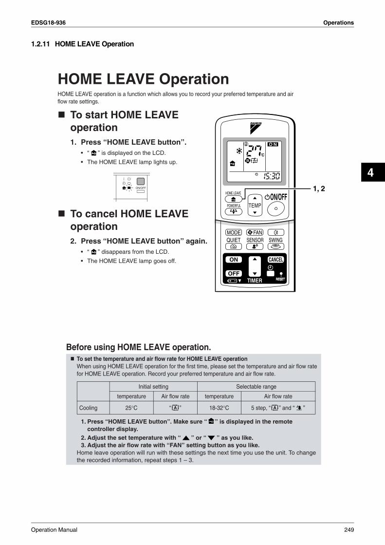
EDSG18-936 Operations
4
1.2.11 HOME LEAVE Operation
HOME LEAVE OperationHOME LEAVE operation is a function which allows you to record your preferred temperature and air flow rate settings.
To start HOME LEAVE operation1. Press “HOME LEAVE button”.
• “ ” is displayed on the LCD.
• The HOME LEAVE lamp lights up.
To cancel HOME LEAVE operation2. Press “HOME LEAVE button” again.
• “ ” disappears from the LCD.
• The HOME LEAVE lamp goes off.
Before using HOME LEAVE operation.To set the temperature and air flow rate for HOME LEAVE operationWhen using HOME LEAVE operation for the first time, please set the temperature and air flow rate for HOME LEAVE operation. Record your preferred temperature and air flow rate.
1. Press “HOME LEAVE button”. Make sure “ ” is displayed in the remote controller display.
2. Adjust the set temperature with “ ” or “ ” as you like.3. Adjust the air flow rate with “FAN” setting button as you like.
Home leave operation will run with these settings the next time you use the unit. To change the recorded information, repeat steps 1 – 3.
TIMER
ON CANCEL
OFF
1, 2
Initial setting Selectable range
temperature Air flow rate temperature Air flow rate
Cooling 25°C “ ” 18-32°C 5 step, “ ” and “ ”
Operation Manual 249
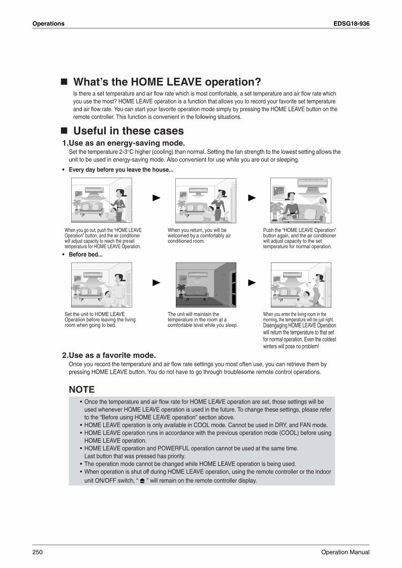
Operations EDSG18-936
What’s the HOME LEAVE operation?Is there a set temperature and air flow rate which is most comfortable, a set temperature and air flow rate which you use the most? HOME LEAVE operation is a function that allows you to record your favorite set temperature and air flow rate. You can start your favorite operation mode simply by pressing the HOME LEAVE button on the remote controller. This function is convenient in the following situations.
Useful in these cases1.Use as an energy-saving mode.
Set the temperature 2-3°C higher (cooling) than normal. Setting the fan strength to the lowest setting allows the unit to be used in energy-saving mode. Also convenient for use while you are out or sleeping.
• Every day before you leave the house...
• Before bed...
2.Use as a favorite mode.Once you record the temperature and air flow rate settings you most often use, you can retrieve them by pressing HOME LEAVE button. You do not have to go through troublesome remote control operations.
NOTE
When you go out, push the “HOME LEAVE Operation” button, and the air conditioner will adjust capacity to reach the preset temperature for HOME LEAVE Operation.
When you return, you will be welcomed by a comfortably air conditioned room.
Push the “HOME LEAVE Operation” button again, and the air conditioner will adjust capacity to the set temperature for normal operation.
Set the unit to HOME LEAVE Operation before leaving the living room when going to bed.
The unit will maintain the temperature in the room at a comfortable level while you sleep.
When you enter the living room in the morning, the temperature will be just right. Disengaging HOME LEAVE Operation will return the temperature to that set for normal operation. Even the coldest winters will pose no problem!
• Once the temperature and air flow rate for HOME LEAVE operation are set, those settings will be used whenever HOME LEAVE operation is used in the future. To change these settings, please refer to the “Before using HOME LEAVE operation” section above.
• HOME LEAVE operation is only available in COOL mode. Cannot be used in DRY, and FAN mode.• HOME LEAVE operation runs in accordance with the previous operation mode (COOL) before using
HOME LEAVE operation.• HOME LEAVE operation and POWERFUL operation cannot be used at the same time.
Last button that was pressed has priority.• The operation mode cannot be changed while HOME LEAVE operation is being used.• When operation is shut off during HOME LEAVE operation, using the remote controller or the indoor
unit ON/OFF switch, “ ” will remain on the remote controller display.
250 Operation Manual

EDSG18-936 Operations
4
1.2.12 INTELLIGENT EYE Operation
FTKS25/35D
INTELLIGENT EYE Operation“INTELLIGENT EYE” is the infrared sensor which detects the human movement.
To start INTELLIGENT EYE operation
1. Press “SENSOR button”.• “ ” is displayed on the LCD.
To cancel the INTELLIGENT EYE operation
2. Press “SENSOR button” again.• “ ” disappears from the LCD.
[EX.]
TEMPON/OFF
POWERFUL
MODE FAN SWINGQUIET SENSOR
ECONO
MOLD PROOF
TIMER
ON CANCEL
OFF
1, 2
When somebody in the room
• Normal operation.
When nobody in the room
• 20 min. after, start energy saving operation.
Somebody back in the room
• Back to normal operation.
Operation Manual 251

Operations EDSG18-936
“INTELLIGENT EYE” is useful for Energy Saving.
Notes on “INTELLIGENT EYE”
CAUTION
Energy saving operation• Change the temperature +2°C in cooling / +2°C in dry mode from set temperature.• Decrease the air flow rate slightly in fan operation. (In FAN mode only)
• Application range is as follows.
• Sensor may not detect moving objects further than 7m away. (Check the application range)• Sensor detection sensitivity changes according to indoor unit location, the speed of pass-
ersby, temperature range, etc.• The sensor also mistakenly detects pets, sunlight, fluttering curtains and light reflected off of
mirrors as passersby.• INTELLIGENT EYE operatipon will not go on during powerful operation.• Night set mode will not go on during you use INTELLIGENT EYE operation.
• Do not place large objects near the sensor.Also keep heating units or humidifiers outside the sensor’s detection area. This sensor can detect objects it shouldn’t as well as not detect objects it should.
• Do not hit or violently push the INTELLIGENT EYE sensor. This can lead to damage and malfunction.
90˚
55˚7m
55˚
7m
Vertical angle 90˚(Side View)
Horizontal angle 110˚(Top View)
252 Operation Manual

EDSG18-936 Operations
4
FTKS50/60/71F, FTKS50B
18
INTELLIGENT EYE Operation“INTELLIGENT EYE” is the infrared sensor which detects the human movement.
To start INTELLIGENT EYE operation
1. Press “SENSOR button”.• “ ” is displayed on the LCD.
To cancel the INTELLIGENT EYE operation
2. Press “SENSOR button” again.• “ ” disappears from the LCD.
[EX.]
TIMER
ON CANCEL
OFF
1, 2
When somebody in the room
• Normal operation
When nobody in the room
• 20 min. after, start energy saving operation.
Somebody back in the room
• Back to normal operation.
Operation Manual 253

Operations EDSG18-936
19
“INTELLIGENT EYE” is useful for Energy Saving.
Notes on “INTELLIGENT EYE”
CAUTION
Energy saving operation• Change the temperature +2°C in cooling / +1°C in dry mode from set temperature.• Decrease the air flow rate slightly in fan operation. (In FAN mode only)
• Application range is as follows.
• Sensor may not detect moving objects further than 7m away. (Check the application range)• Sensor detection sensitivity changes according to indoor unit location, the speed of
passersby, temperature range, etc.• The sensor also mistakenly detects pets, sunlight, fluttering curtains and light reflected off of
mirrors as passersby.• INTELLIGENT EYE operation will not go on during powerful operation.• Night set mode (page 20.) will not go on during you use INTELLIGENT EYE operation.
• Do not place large objects near the sensor.Also keep heating units or humidifiers outside the sensor’s detection area. This sensor can detect objects it shouldn’t as well as not detect objects it should.
• Do not hit or violently push the INTELLIGENT EYE sensor. This can lead to damage and malfunction.
90°55°
7m55°
7m
Vertical angle 90°(Side View)
Horizontal angle 110°(Top View)
254 Operation Manual

EDSG18-936 Operations
4
1.2.13 TIMER Operation
TIMER OperationTimer functions are useful for automatically switching the air conditioner on or off at night or in the morning. You can also use OFF TIMER and ON TIMER in combination.
To use OFF TIMER operation• Check that the clock is correct.
If not, set the clock to the present time.
1. Press “OFF TIMER button”.
is displayed.
blinks.
2. Press “TIMER Setting button” until the time setting reaches the point you like.• Every pressing of either button increases
or decreases the time setting by 10 minutes. Holding down either button changes the setting rapidly.
3. Press “OFF TIMER button” again.• The TIMER lamp lights up.
To cancel the OFF TIMER Operation4. Press “CANCEL button”.
• The TIMER lamp goes off.
NOTE• When TIMER is set, the present time is not displayed.• Once you set ON, OFF TIMER, the time setting is kept in the memory. (The memory is canceled when
remote controller batteries are replaced.)• When operating the unit via the ON/OFF Timer, the actual length of operation may vary from the time
entered by the user. (Maximum approx. 10 minutes)
NIGHT SET MODEWhen the OFF TIMER is set, the air conditioner automatically adjusts the temperature setting (0.5˚C up in COOL) to prevent excessive cooling for your pleasant sleep.
TIMER
ON CANCEL
OFF
42
1, 3
Operation Manual 255
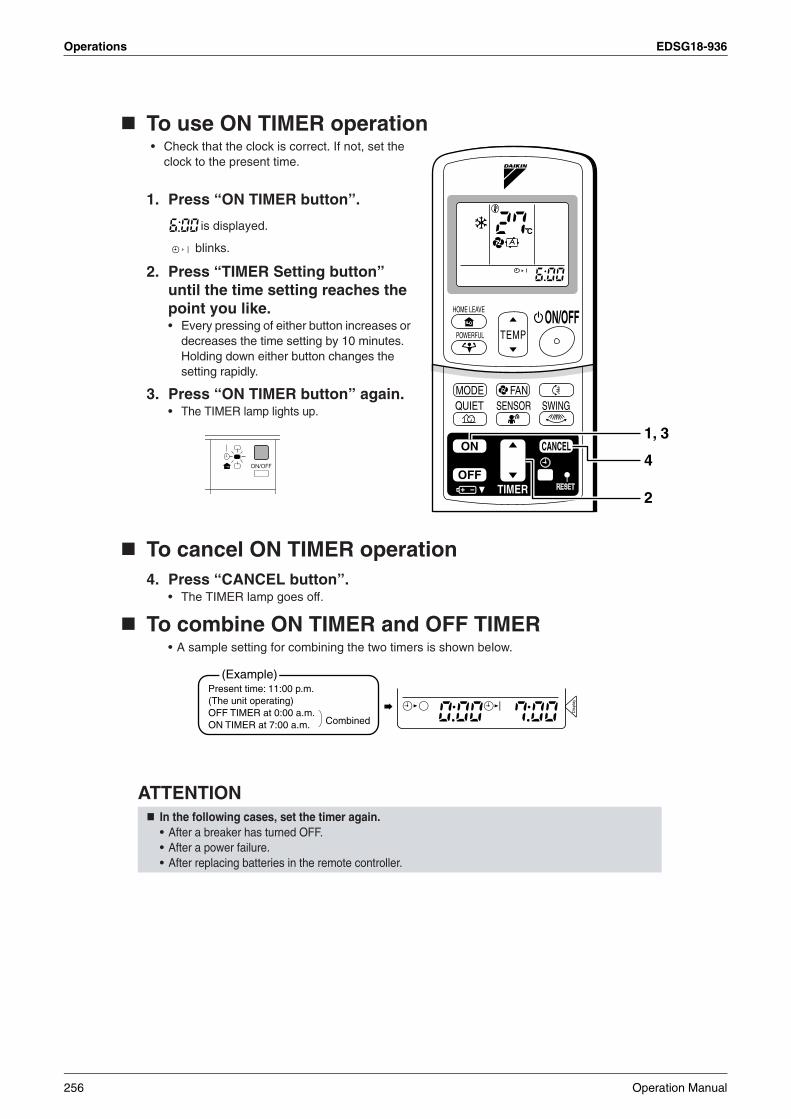
Operations EDSG18-936
To use ON TIMER operation• Check that the clock is correct. If not, set the
clock to the present time.
1. Press “ON TIMER button”.
is displayed.
blinks.
2. Press “TIMER Setting button” until the time setting reaches the point you like.• Every pressing of either button increases or
decreases the time setting by 10 minutes. Holding down either button changes the setting rapidly.
3. Press “ON TIMER button” again.• The TIMER lamp lights up.
To cancel ON TIMER operation4. Press “CANCEL button”.
• The TIMER lamp goes off.
To combine ON TIMER and OFF TIMER• A sample setting for combining the two timers is shown below.
ATTENTIONIn the following cases, set the timer again.• After a breaker has turned OFF.• After a power failure.• After replacing batteries in the remote controller.
TIMER
ON CANCEL
OFF
2
1, 3
4
(Example)Present time: 11:00 p.m. (The unit operating)OFF TIMER at 0:00 a.m.ON TIMER at 7:00 a.m. Combined
Dis
play
256 Operation Manual
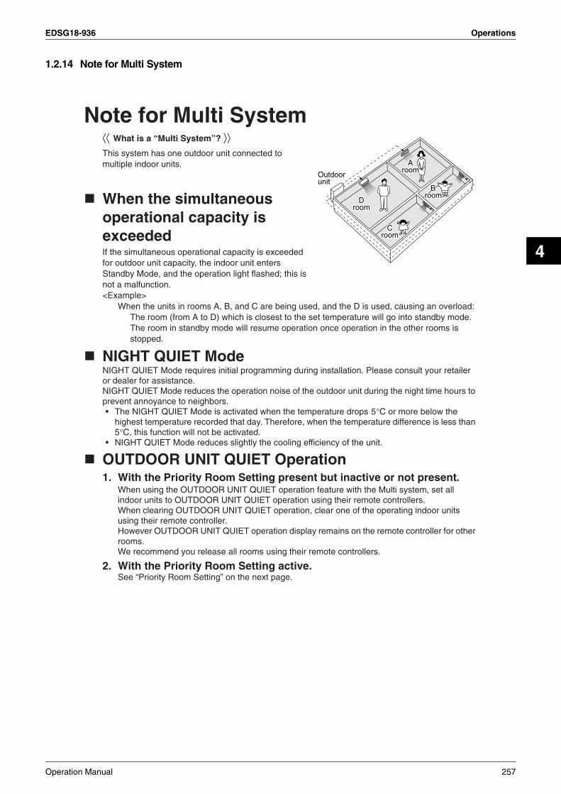
EDSG18-936 Operations
4
1.2.14 Note for Multi System
Note for Multi System⟨⟨ What is a “Multi System”? ⟩⟩This system has one outdoor unit connected to multiple indoor units.
When the simultaneous operational capacity is exceededIf the simultaneous operational capacity is exceeded for outdoor unit capacity, the indoor unit enters Standby Mode, and the operation light flashed; this is not a malfunction.<Example>
When the units in rooms A, B, and C are being used, and the D is used, causing an overload:The room (from A to D) which is closest to the set temperature will go into standby mode. The room in standby mode will resume operation once operation in the other rooms is stopped.
NIGHT QUIET ModeNIGHT QUIET Mode requires initial programming during installation. Please consult your retailer or dealer for assistance.NIGHT QUIET Mode reduces the operation noise of the outdoor unit during the night time hours to prevent annoyance to neighbors.• The NIGHT QUIET Mode is activated when the temperature drops 5°C or more below the
highest temperature recorded that day. Therefore, when the temperature difference is less than 5°C, this function will not be activated.
• NIGHT QUIET Mode reduces slightly the cooling efficiency of the unit.
OUTDOOR UNIT QUIET Operation 1. With the Priority Room Setting present but inactive or not present.
When using the OUTDOOR UNIT QUIET operation feature with the Multi system, set all indoor units to OUTDOOR UNIT QUIET operation using their remote controllers.When clearing OUTDOOR UNIT QUIET operation, clear one of the operating indoor units using their remote controller.However OUTDOOR UNIT QUIET operation display remains on the remote controller for other rooms.We recommend you release all rooms using their remote controllers.
2. With the Priority Room Setting active.See “Priority Room Setting” on the next page.
CCroomroom
BBroomroom
AAroomroom
DDroomroom
Croom
Broom
Aroom
Droom
Outdoorunit
Operation Manual 257

Operations EDSG18-936
Priority Room SettingThe Priority Room Setting requires initial programming during installation. Please consult your retailer or dealer for assistance.The room designated as the Priority Room takes priority in the following situations;
1. Operation Mode Priority.As the operation mode of the Priority Room takes precedence, the user can select a different operation mode from other rooms.⟨Example⟩
* Room A is the Priority Room in the examples.When COOL mode is selected in Room A while operating the following modes in Room B,C and D:
2. Priority when POWERFUL operation is used.⟨Example⟩
* Room A is the Priority Room in the examples.The indoor units in Rooms A,B,C and D are all operating. If the unit in Room A enters POWERFUL operation, operation capacity will be concentrated in Room A. In such a case, the cooling efficiency of the units in Rooms B,C and D may be slightly reduced.
3. Priority when using OUTDOOR UNIT QUIET operation.⟨Example⟩
* Room A is the Priority Room in the examples.Just by setting the unit in Room A to QUIET operation, the air conditioner starts OUTDOOR UNIT QUIET operation.You don’t have to set all the operated indoor units to QUIET operation.
Operation mode in Room B, C and D Status of Room B, C and D when the unit in Room A is in COOL mode
COOL or DRY or FAN Current operation mode maintained
258 Operation Manual

EDSG18-936 Operations
4
1.2.15 Care and Cleaning
FTKS25/35D
Care and CleaningCAUTION
Indoor unit, Outdoor unit and Remote controller
1. Wipe them with dry soft cloth.
Front panel1. Open the front panel.
• Hold the panel by the tabs on the two sides and lift it unitl it stops with a click.
2. Remove the front panel.• Lift the front panel up, slide it slightly to the right,
and remove it from the horizontal axle.
3. Clean the front panel.• Wipe it with a soft cloth soaked in water.• Only neutral detergent may be used.• In case of washing the panel with water, dry it with
cloth, dry it up in the shade after washing.
4. Attach the front panel.• Set the 2 keys of the front panel into the slots
and push them in all the way.• Close the front panel slowly and push the
panel at the 3 points.(1 on each sides and 1 in the middle.)
CAUTION
Units
• Don’t touch the metal parts of the indoor unit. If you touch those parts, this may cause an injury.• When removing or attaching the front panel, use a robust and stable stool and watch your steps carefully. • When removing or attaching the front panel, support the panel securely with hand to prevent it from falling.• For cleaning, do not use hot water above 40 °C, benzine, gasoline, thinner, nor other volatile oils, pol-
ishing compound, scrubbing brushes, nor other hand stuff.• After cleaning, make sure that the front panel is securely fixed.
Before cleaning, be sure to stop the operation and turn the breaker OFF.
Fit the keyinto the slot.
Operation Manual 259
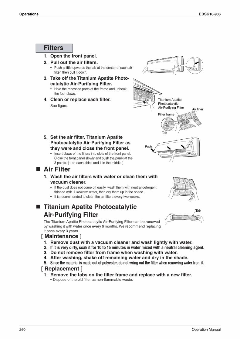
Operations EDSG18-936
1. Open the front panel. 2. Pull out the air filters.
• Push a little upwards the tab at the center of each air filter, then pull it down.
3. Take off the Titanium Apatite Photo-catalytic Air-Purifying Filter.• Hold the recessed parts of the frame and unhook
the four claws.
4. Clean or replace each filter.See figure.
5. Set the air filter, Titanium Apatite Photocatalytic Air-Purifying Filter as they were and close the front panel.• Insert claws of the filters into slots of the front panel.
Close the front panel slowly and push the panel at the 3 points. (1 on each sides and 1 in the middle.)
Air Filter1. Wash the air filters with water or clean them with
vacuum cleaner.• If the dust does not come off easily, wash them with neutral detergent
thinned with lukewarm water, then dry them up in the shade.• It is recommended to clean the air filters every two weeks.
Titanium Apatite Photocatalytic Air-Purifying FilterThe Titanium Apatite Photocatalytic Air-Purifying Filter can be renewed by washing it with water once every 6 months. We recommend replacing it once every 3 years.
[ Maintenance ]1. Remove dust with a vacuum cleaner and wash lightly with water.2. If it is very dirty, soak it for 10 to 15 minutes in water mixed with a neutral cleaning agent.3. Do not remove filter from frame when washing with water.4. After washing, shake off remaining water and dry in the shade.5. Since the material is made out of polyester, do not wring out the filter when removing water from it.
[ Replacement ]1. Remove the tabs on the filter frame and replace with a new filter.
• Dispose of the old filter as non-flammable waste.
Filters
Air filter
Titanium Apatite Photocatalytic Air-Purifying Filter
Filter frame
Tab
Push
Tab
260 Operation Manual

EDSG18-936 Operations
4
NOTE
Check
Before a long idle period
1. Operate the “FAN only” for several hours on a fine day to dry out the inside.• Press “MODE selector button” and select “fan” operation.
• Press “ON/OFF button” and start operation.
2. Clean the air filters and set them again.
3. Take out batteries from the remote controller.
4. Turn OFF the breaker for the room air conditioner.• When a multi outdoor unit is connected, make sure the heating operation is not used at the
other room before you use the fan operation.
• Operation with dirty filters: (1) cannot deodorize the air. (2) cannot clean the air. (3) results in poor cooling. (4) may cause odour.
• To order Titanium Apatite Photocatalytic Air-Purifying Filter contact to the service shop there you bought the air conditioner.
• Dispose of the old filter as non-flammable waste.
Check that the base, stand and other fittings of the outdoor unit are not decayed or corroded.
Check that nothing blocks the air inlets and the outlets of the indoor unit and the outdoor unit.
Check that the drain comes smoothly out of the drain hose during COOL or DRY operation.• If no drain water is seen, water may be leaking from the indoor unit. Stop operation and consult the ser-
vice shop if this is the case.
Item Part No.
Titanium Apatite Photocatalytic Air-Purifying Filter. (without frame) 1 set KAF970A46
Operation Manual 261

Operations EDSG18-936
FTKS50/60/71F
Care and CleaningCAUTION
Indoor unit, Outdoor unit and Remote controller1. Wipe them with dry soft cloth.
Front panel1. Open the front panel.
• Hold the panel by the tabs on the two sides and lift it until it stops with a click.
2. Remove the front panel.• Open the front panel further while sliding
it to either the left or right and pulling it toward you. This will disconnect the rotation dowel on one side. Then disconnect the rotation dowel on the other side in the same manner.
3. Clean the front panel.• Wipe it with a soft cloth soaked in water.• Only neutral detergent may be used.• In case of washing the panel with water, dry it with cloth, dry it up in the shade after washing.
4. Attach the front panel.• Align the rotation dowels on the left and right of the front panel
with the slots, then push them all the way in.• Close the front panel slowly. (Press the panel at both sides
and the center.)
CAUTION
Units
• Don’t touch the metal parts of the indoor unit. If you touch those parts, this may cause an injury.• When removing or attaching the front panel, use a robust and stable stool and watch your steps carefully.• When removing or attaching the front panel, support the panel securely with hand to prevent it from falling.• For cleaning, do not use hot water above 40°C, benzine, gasoline, thinner, nor other volatile oils,
polishing compound, scrubbing brushes, nor other hand stuff.• After cleaning, make sure that the front panel is securely fixed.
Before cleaning, be sure to stop the operation and turn the breaker OFF.
262 Operation Manual

EDSG18-936 Operations
4
1. Open the front panel.
2. Pull out the air filters.• Push a little upwards the tab at the
center of each air filter, then pull it down.
3. Take off the Titanium Apatite Photocatalytic Air-Purifying Filter.• Press the top of the air-
cleaning filter onto the tabs (3 tabs at top). Then press the bottom of the filter up slightly, and press it onto the tabs (3 at bottom).
4. Clean or replace each filter.See figure.
5. Set the air filter and the Titanium Apatite Photocatalytic Air-Purifying Filter as they were and close the front panel.• Press the front panel at both sides and the
center.
Air Filter1. Wash the air filters with water or clean them with
vacuum cleaner.• If the dust does not come off easily, wash them with neutral
detergent thinned with lukewarm water, then dry them up in the shade.
• It is recommended to clean the air filters every two weeks.
Titanium Apatite Photocatalytic Air-purifying Filter The Titanium Apatite Photocatalytic Air-Purifying Filter can be renewed by washing it with water once every 6 months. We recommend replacing it once every 3 years.
[ Maintenance ]1. Remove dust with a vacuum cleaner and wash lightly with water.2. If it is very dirty, soak it for 10 to 15 minutes in water mixed with a neutral cleaning agent.3. After washing, shake off remaining water and dry in the shade.4. Since the material is made out of polyester, do not wring out the filter when removing water
from it.[ Replacement ]1. Remove the tabs on the filter frame and replace with a new filter.
• Dispose of the old filter as non-flammable waste.
Filters
tabs (3 tabs at top)
tabs (3 at bottom)
Operation Manual 263

Operations EDSG18-936
NOTE
Check
Before a long idle period
1. Operate the “FAN only” for several hours on a fine day to dry out the inside.• Press “MODE” button and select “FAN” operation.
• Press “ON/OFF” button and start operation.
2. After operation stops, turn off the breaker for the room air conditioner.
3. Clean the air filters and set them again.
4. Take out batteries from the remote controller.
• Operation with dirty filters: (1) cannot deodorize the air. (2) cannot clean the air. (3) results in poor cooling. (4) may cause odour.
• To order Titanium Apatite Photocatalytic Air-Purifying Filter contact to the service shop there you bought the air conditioner.
• Dispose of old filters as non-flammable waste.
Check that the base, stand and other fittings of the outdoor unit are not decayed or corroded.
Check that nothing blocks the air inlets and the outlets of the indoor unit and the outdoor unit.
Check that the drain comes smoothly out of the drain hose during COOL or DRY operation.• If no drain water is seen, water may be leaking from the indoor unit. Stop operation and consult the
service shop if this is the case.
Item Part No.
Titanium Apatite Photocatalytic Air-Purifying Filter (without frame) 1 set KAF952B42
264 Operation Manual

EDSG18-936 Operations
4
FTKS50B
Care and CleaningCAUTION
Indoor unit, Outdoor unit and Remote controller1. Wipe them with dry soft cloth.
Front grille1. Open the front grille.
• Hold the grille by the tabs on the two sides and lift it until it stops with a click.
2. Remove the front grille.• Open the front panel further while
sliding it to either the left or right and pulling it toward you. This will disconnect the rotation dowel on one side. Then disconnect the rotation dowel on the other side in the same manner.
3. Clean the front grille• Wipe it with a soft cloth soaked in water.• Only neutral detergent may be used.• In case of washing the grille with water, dry it with cloth, dry it up in the shade after washing.
4. Attach the front grille• Align the rotation dowels on the left and right of the front panel with
the slots, then push them all the way in.• Close the front panel slowly. (Press the panel at both sides and the
center.)
CAUTION
Units
• When the packaging materials are attached to the front panel, please remove them.
• Don’t touch the metal parts of the indoor unit. If you touch those parts, this may cause an injury.
• When removing or attaching the front grille, use a robust and stable stool and watch your steps carefully.
• When removing or attaching the front grille, support the grille securely with hand to prevent it from falling.
• For cleaning, do not use hot water above 40 °C, benzine, gasoline, thinner, nor other volatile oils, polishing compound, scrubbing brushes, nor other hand stuff.
• After cleaning, make sure that the front grille is securely fixed.
Before cleaning, be sure to stop the operation and turn the breaker OFF.
Operation Manual 265

Operations EDSG18-936
1. Open the front grille. 2. Pull out the air filters.
• Push a little upwards the tab at the center of each air filter, then pull it down.
3. Take off the air purifying filter with photocatalytic deodorizing function.• Press the top of the air-cleaning
filter onto the tabs (3 tabs at top). Then press the bottom of the filter up slightly, and press it onto the tabs (2 at bottom)(3 at bottom).
4. Clean or replace each filter.See figure.
5. Set the air filter and the air purifying filter with photocalytic deodorizing function as they were and close the front grille.• Press the front panel at both sides and the center.
Air Filter1. Wash the air filters with water or clean them with vacuum cleaner.
• If the dust does not come off easily, wash them with neutral detergent thinned with lukewarm water, then dry them up in the shade.
• It is recommended to clean the air filters every two weeks.
Air purifying filter with photocatalytic deodorizing function. (gray)The air purifying capacity of the photocatalytic purifying filter can be renewed by washing it with water once every 6 months. We recommend replacing it once every 3 years.
[ Maintenance ]1. Remove dust with a vacuum cleaner and wash lightly with water.2. If it is very dirty, soak it for 10 to 15 minutes in water mixed with a neutral cleaning agent.3. After washing, shake off remaining water and dry in the shade.4. Since the material is made out of paper, do not wring out the filter when removing water from it.[ Replacement]1. Remove the tabs on the filter frame and replace with a new filter.
• Dispose of the old filter as flammable waste.
Filters
tabs (3 tabs at top)
tabs (2 at bottom)50class
tabs (3 tabs at top)
tabs (3 at bottom)60,71class
266 Operation Manual

EDSG18-936 Operations
4
Check
Before a long idle period
1. Operate the “FAN only” for several hours on a fine day to dry out the inside.• Press “MODE” button and select “FAN” operation.
• Press “ON/OFF” button and start operation.
2. After operation stops, turn off the breaker for the room air conditioner.
3. Clean the air filters and set them again.
4. Take out batteries from the remote controller.
NOTE
Check that the base, stand and other fittings of the outdoor unit are not decayed or corroded.
Check that nothing blocks the air inlets and the outlets of the indoor unit and the outdoor unit.
Check that the drain comes smoothly out of the drain hose during COOL or DRY operation.• If no drain water is seen, water may be leaking from the indoor unit. Stop operation and consult the
service shop if this is the case.
• Operation with dirty filters: (1) cannot deodorize the air. (2) cannot clean the air. (3) results in poor heating or cooling. (4) may cause odour.
• To order air purifying filter with photocatalytic deodorizing function contact to the service shop there you bought the air conditioner.
• Dispose of old air filter as non-burnable and photocatalytic deodorizing filters as burnable waste.
Item Part No.
Air purifying filter with photocatalytic deodorizing function. (without frame) 1 set KAF952A42
Operation Manual 267

Operations EDSG18-936
FDKS25/35CA
Care and Cleaning
CAUTION
Cleaning the air filter1.Removing the air filter.• Rear suction
Pull the bottom side of the air filter backwards, over the 3 bends.• Bottom suction
Pull the filter over the 3 bends situated at the backside of the unit.2.Cleaning the air filter.
Remove dust from the air filter using a vacuum cleaner and gently rinse them in cool water. Do not use detergent or hot water to avoid filter shrinking or deformation. After cleaning dry them in the shade.
3.Replacing the air filter.• Rear suction
Hook the filter behind the flap situated at the top of the unit and push the other side gently over the 3 bends.
• Bottom suctionHook the filter behind the flap situated at the middle of the unit and push the other side gently over the 3 bends.
• Only a qualified service person is allowed to perform maintenance.
• Before cleaning, be sure to stop the operation and turn the breaker OFF.
In case of back side In case of bottom side
Main unit
Filter
Attach the filter to the main unit while pushing down on the tabs.Force
Force
268 Operation Manual
EDSG18-936 Operations
4
Cleaning the drain pan• Clean the drain pan periodically, or drain piping may be clogged with dust and may result in water leakage.
Ask your DAIKIN dealer to clean them.• Prepare a cover locally to prevent any dust in the air around the indoor unit from getting in the drain pan, if
there is a great deal of dust present.
CAUTION
Check
Before a long idle period1. Operate the “FAN only” for several hours on a fine day to dry out the inside.
• Press “MODE selector button” and select “FAN” operation.
• Press “ON/OFF button” and start operation.
2. After operation stops, turn off the breaker for the room air conditioner.
3. Clean the air filters and set them again.
4. Take out batteries from the remote controller.• When a multi outdoor unit is connected, make sure the heating operation is not used at the
other room before you use the fan operation.
• Do not operate the air conditioner without filters, this to avoid dust accummulation inside the unit.
• Do not remove the air filter except when cleaning.Unnecessary handling may damage the filter.
• Do not use gasoline, benzene, thinner, polishing powder, liquid insecticide, It may cause discoloring or warping.
• Do not let the indoor unit get wet. It may cause an electric shock or a fire.• Operation with dusty air filters lowers the cooling and heating capacity and wastes energy.• The suction grille is option.• Do not use water or air of 50˚C or higher for cleaning air filters and outside panels.
Check that the base, stand and other fittings of the outdoor unit are not decayed or corroded.
Check that nothing blocks the air inlets and the outlets of the indoor unit and the outdoor unit.
Check that the drain comes smoothly out of the drain hose during COOL or DRY operation.• If no drain water is seen, water may be leaking from the indoor unit. Stop operation and consult the ser-
vice shop if this is the case.
Operation Manual 269
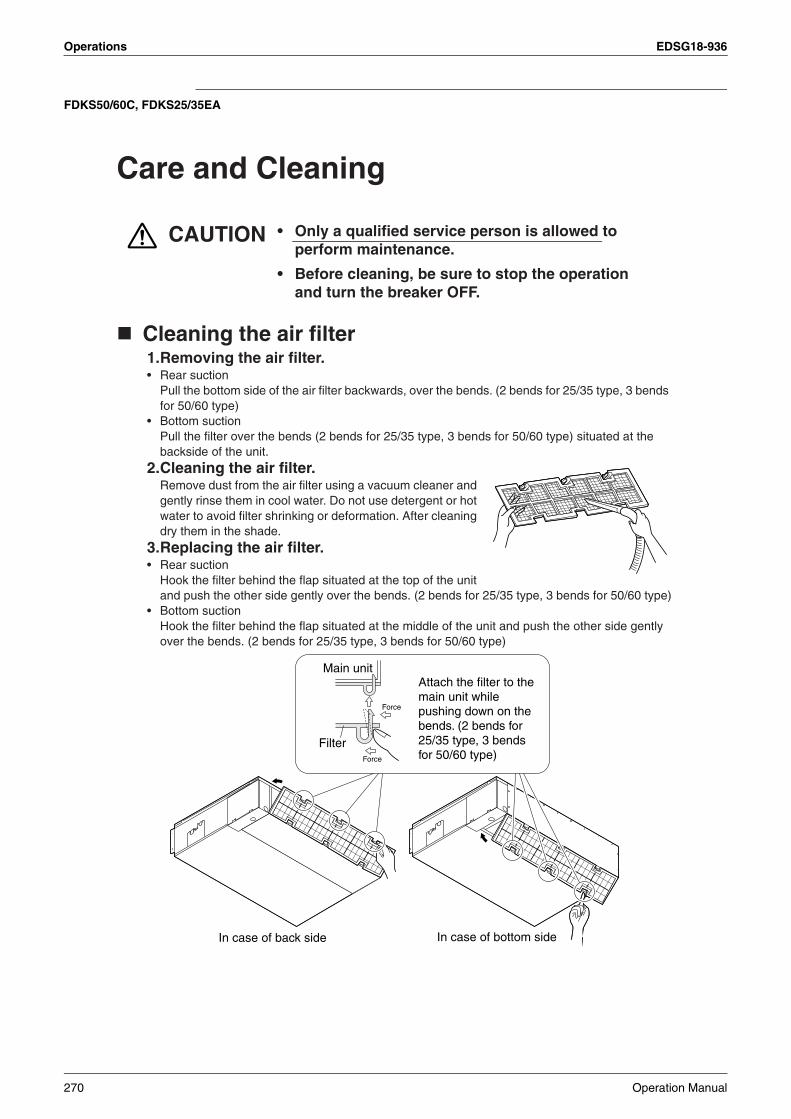
Operations EDSG18-936
FDKS50/60C, FDKS25/35EA
Care and Cleaning
CAUTION
Cleaning the air filter1.Removing the air filter.• Rear suction
Pull the bottom side of the air filter backwards, over the bends. (2 bends for 25/35 type, 3 bends for 50/60 type)
• Bottom suctionPull the filter over the bends (2 bends for 25/35 type, 3 bends for 50/60 type) situated at the backside of the unit.
2.Cleaning the air filter.Remove dust from the air filter using a vacuum cleaner and gently rinse them in cool water. Do not use detergent or hot water to avoid filter shrinking or deformation. After cleaning dry them in the shade.
3.Replacing the air filter.• Rear suction
Hook the filter behind the flap situated at the top of the unit and push the other side gently over the bends. (2 bends for 25/35 type, 3 bends for 50/60 type)
• Bottom suctionHook the filter behind the flap situated at the middle of the unit and push the other side gently over the bends. (2 bends for 25/35 type, 3 bends for 50/60 type)
• Only a qualified service person is allowed to perform maintenance.
• Before cleaning, be sure to stop the operation and turn the breaker OFF.
In case of back side In case of bottom side
Main unit
Filter
Attach the filter to the main unit while pushing down on the bends. (2 bends for 25/35 type, 3 bends for 50/60 type)Force
Force
270 Operation Manual

EDSG18-936 Operations
4
Cleaning the drain pan• Clean the drain pan periodically, or drain piping may be clogged with dust and may result in water leakage.
Ask your DAIKIN dealer to clean them.• Prepare a cover locally to prevent any dust in the air around the indoor unit from getting in the drain pan, if
there is a great deal of dust present.
CAUTION
Check
Before a long idle period1. Operate the “FAN only” for several hours on a fine day to dry out the inside.
• Press “MODE selector button” and select “FAN” operation.
• Press “ON/OFF button” and start operation.
2. Clean the air filters and set them again.
3. Take out batteries from the remote controller.
4. Turn OFF the breaker for the room air conditioner.• When a multi outdoor unit is connected, make sure the heating operation is not used at the
other room before you use the fan operation.
• Do not operate the air conditioner without filters, this to avoid dust accumulation inside the unit.
• Do not remove the air filter except when cleaning.Unnecessary handling may damage the filter.
• Do not use gasoline, benzene, thinner, polishing powder, liquid insecticide, It may cause discoloring or warping.
• Do not let the indoor unit get wet. It may cause an electric shock or a fire.• Operation with dusty air filters lowers the cooling and heating capacity and wastes energy.• The suction grille is option.• Do not use water or air of 50˚C or higher for cleaning air filters and outside panels.• Ask your DAIKIN dealer how to clean it.
Check that the base, stand and other fittings of the outdoor unit are not decayed or corroded.
Check that nothing blocks the air inlets and the outlets of the indoor unit and the outdoor unit.
Check that the drain comes smoothly out of the drain hose during COOL or DRY operation.• If no drain water is seen, water may be leaking from the indoor unit. Stop operation and consult the ser-
vice shop if this is the case.
Operation Manual 271

Operations EDSG18-936
1.2.16 Troubleshooting
Trouble Shooting
The following cases are not air conditioner troubles but have some reasons. You may just continue using it.
These cases are not troubles.
Case ExplanationOperation does not start soon.• When ON/OFF button was
pressed soon after operation was stopped.
• When the mode was reselected.
• This is to protect the air conditioner.You should wait for about 3 minutes.
The outdoor unit emits water or steam.
In COOL or DRY mode• Moisture in the air condenses into water on the cool
surface of outdoor unit piping and drips.
Mists come out of the indoor unit.
This happens when the air in the room is cooled into mist by the cold air flow during cooling operation.
The indoor unit gives out odour. This happens when smells of the room, furniture, or cigarettes are absorbed into the unit and discharged with the air flow.(If this happens, we recommend you to have the indoor unit washed by a technician. Consult the service shop where you bought the air conditioner.)
The outdoor fan rotates while the air conditioner is not in operation.
After operation is stopped:• The outdoor fan continues rotating for another 60
seconds for system protection.While the air conditioner is not in operation:• When the outdoor temperature is very high, the out door
fan starts rotating for system protection.
The operation stopped suddenly.(OPERATION lamp is on.)
For system protection, the air conditioner may stop operating on a sudden large voltage fluctuation.It automatically resumes operation in about 3 minutes.
272 Operation Manual

EDSG18-936 Operations
4
Please check again before calling a repair person.
Check again.
Case CheckThe air conditioner does not operate.(OPERATION lamp is off.)
• Hasn't a breaker turned OFF or a fuse blown?
• Isn't it a power failure?
• Are batteries set in the remote controller?
• Is the timer setting correct?
Cooling effect is poor. • Are the air filters clean?
• Is there anything to block the air inlet or the outlet of the indoor and the outdoor units?
• Is the temperature setting appropriate?
• Are the windows and doors closed?
• Are the air flow rate and the air direction set appropriately?
• Is the unit set to the INTELLIGENT EYE mode?
Operation stops suddenly.(OPERATION lamp flashes.)
• Are the air filters clean?
• Is there anything to block the air inlet or the outlet of the indoor and the outdoor units?Clean the air filters or take all obstacles away and turn the breaker OFF. Then turn it ON again and try operating the air conditioner with the remote controller. If the lamp still flashes, call the service shop where you bought the air conditioner.
• Are operation modes all the same for indoor units connected to outdoor units in the multi system?If not, set all indoor units to the same operation mode and confirm that the lamps flash.
An abnormal functioninghappens during operation.
• The air conditioner may malfunction with lightning or radio waves. Turn the breaker OFF, turn it ON again and try operating the air conditioner with the remote controller.
Operation Manual 273
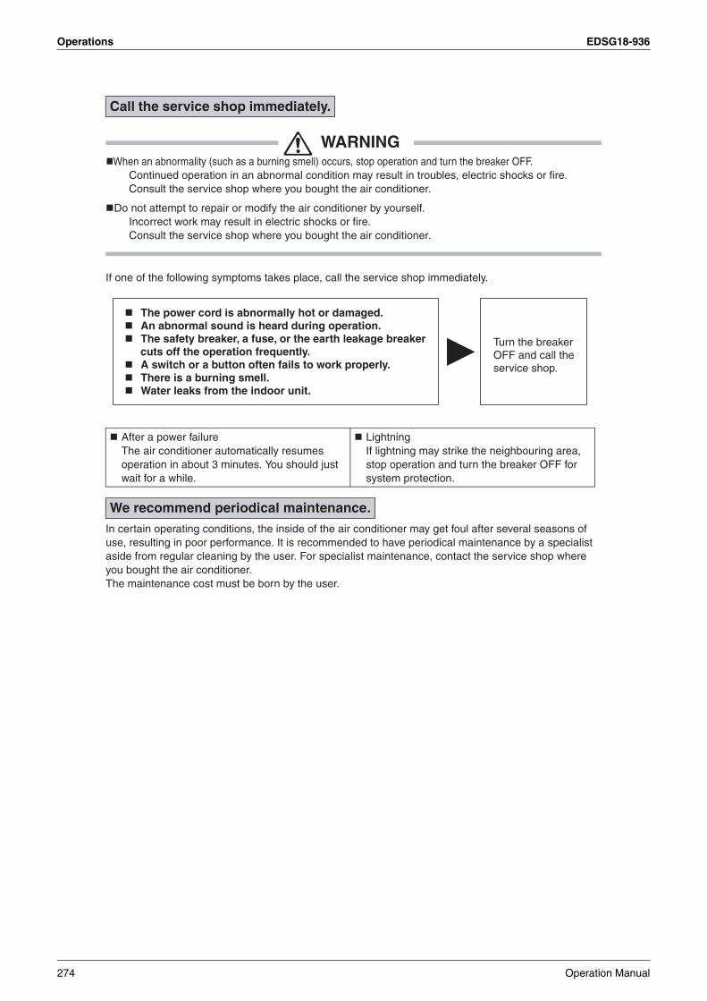
Operations EDSG18-936
WARNINGWhen an abnormality (such as a burning smell) occurs, stop operation and turn the breaker OFF.
Continued operation in an abnormal condition may result in troubles, electric shocks or fire.Consult the service shop where you bought the air conditioner.
Do not attempt to repair or modify the air conditioner by yourself.Incorrect work may result in electric shocks or fire.Consult the service shop where you bought the air conditioner.
If one of the following symptoms takes place, call the service shop immediately.
In certain operating conditions, the inside of the air conditioner may get foul after several seasons of use, resulting in poor performance. It is recommended to have periodical maintenance by a specialist aside from regular cleaning by the user. For specialist maintenance, contact the service shop where you bought the air conditioner.The maintenance cost must be born by the user.
Call the service shop immediately.
After a power failureThe air conditioner automatically resumes operation in about 3 minutes. You should just wait for a while.
LightningIf lightning may strike the neighbouring area, stop operation and turn the breaker OFF for system protection.
We recommend periodical maintenance.
The power cord is abnormally hot or damaged.An abnormal sound is heard during operation.The safety breaker, a fuse, or the earth leakage breaker cuts off the operation frequently. A switch or a button often fails to work properly.There is a burning smell.Water leaks from the indoor unit.
Turn the breaker OFF and call the service shop.
274 Operation Manual

EDSG18-936 Operations
4
1.3 FFQ25/35/50/60B Series
[1]
[1]
1
3
42
TEST
Chr
hrTEST
NOTAVAILABLE
L H
2
1011
3
145
6
7
8
14
1516 17 18
19
20
21
22
12
9
13
a
b
c
d ee
fg
h
i
k
e f
l
d
j
Chr
H
Operation Manual 275

Operations EDSG18-936
1 English
CONTENTSILLUSTRATIONS .............................................. [1]
1. WHAT TO DO BEFOREOPERATION ................................................. 1
2. SAFETY PRECAUTIONS.............................. 23. OPERATION RANGE.................................... 44. INSTALLATION SITE.................................... 45. NAME AND FUNCTION OF EACH SWITCH
AND DISPLAY ON THE REMOTE CONTROLLER.............................................. 5
6. OPERATION PROCEDURE ......................... 57. OPTIMUM OPERATION ............................... 88. MAINTENANCE
(FOR SERVICE PERSONNEL)..................... 89. NOT MALFUNCTION OF THE AIR
CONDITIONER ........................................... 1010. TROUBLE SHOOTING ............................... 11
This operation manual is for the following systems with standard control. Before initiating operation, contact your Daikin dealer for the operation that corresponds to your sysem.• Pair system
• Multi system
NOTE• If the unit you purchased is controlled by a wire-
less remote controller, also refer to the wireless remote controller’s operation manual.
If your installation has a customized control system, ask your Daikin dealer for operation that corre-sponds to your system.
• Heat pump typeThis system provides cooling, heating, automatic, program dry, and fan operation modes.
• Cooling only typeThis system provides cooling, program dry, and fan operation modes.
PRECAUTIONS FOR GROUP CONTROL SYSTEM OR TWO REMOTE CONTROLLER CONTROL SYSTEMThis system provides two other control systems beside individual control (one remote controller con-trols one indoor unit) system. Confirm the following if your unit is of the following control system type.
• Group control system One remote controller controls up to 16 indoor units. All indoor units are equally set.
• Two remote controllers control system Two remote controllers control one indoor unit (In case of group control system, one group of indoor units) The unit is individually operated.
NOTE• Contact your Daikin dealer in case of changing
the combination or setting of group control and two remote controllers control system.
Names and functions of parts
1. WHAT TO DO BEFOREOPERATION
Indoor unit
Unit withremotecontroller
Outdoor unit
Indoor unit
Unit with remotecontroller
Unit with remotecontroller
Indoor unit
Outdoor unit
a Indoor unit
b
Outdoor unit• The external appearance of the outdoor
unit varies depending on its capacity class. The outdoor unit shown in the fig-ure is for reference to indicate features.Contact your Daikin Dealer and verify which outdoor unit you have.
cRemote controllerDepending on the system configuration, the remote controller is not provided.
d Inlet air
e Discharged air
f Air outlet
g Air flow flap (at air outlet)
h Refrigerant piping, connection electric wire
i Drain pipe
j Air inletThe built-in air filter removes dust and dirt.
kDrain pumping out device (built-in)Drains water removed from the room dur-ing cooling.
lGround wireWire to ground from the outdoor unit to pre-vent electrical shocks.
Refer to figure 2 on page [1]
276 Operation Manual

EDSG18-936 Operations
4
English 2
To gain full advantage of the air conditioner’s func-tions and to avoid malfunction due to mishandling, we recommend that you read this instruction man-ual carefully before use. This air conditioner is classified under “appliances not accessible to the general public”.• The precautions described herein are classi-
fied as WARNING and CAUTION. They both contain important information regarding safety. Be sure to observe all precautions without fail.
WARNING ...Failure to follow these instructions properly may result in personal injury or loss of life.
CAUTION ....Failure to observe these instruc-tions properly may result in prop-erty damage or personal injury, which may be serious depending on the circumstances.
• After reading, keep this manual in a conve-nient place so that you can refer to it when-ever necessary. If the equipment is transferred to a new user, be sure also to hand over the manual.
WARNINGBe aware that prolonged, direct exposure to cool or warm air from the air conditioner, or to air that is too cool or too warm can be harmful to your physical condition and health.When the air conditioner is malfunctioning (giving off a burning odour, etc.) turn off power to the unit and contact your local dealer.Continued operation under such circumstances may result in a failure, electric shocks or fire haz-ards.Consult your local dealer about installation work. Doing the work yourself may result in water leak-age, electric shocks or fire hazards.Consult your local dealer regarding modifi-cation, repair and maintenance of the air con-ditioner.Improper workmanship may result in water leak-age, electric shocks or fire hazards.Do not place objects, including rods, your fingers, etc., in the air inlet or outlet. Injury may result due to contact with the air con-ditioner’s highspeed fan blades.Beware of fire in case of refrigerant leakage.If the air conditioner is not operating correctly, i.e. not generating cool or warm air, refrigerant leakage could be the cause. Consult your dealer for assistance. The refrigerant within the air conditioner is safe and normally does not leak.
However, in the event of a leakage, contact with a naked burner, heater or cooker may result in generation of noxious gas. Do not longer use the air conditioner until a qual-ified service person confirms that the leakage has been repaired.Consult your local dealer regarding what to do in case of refrigerant leakage.When the air conditioner is to be installed in a small room, it is necessary to take proper mea-sures so that the amount of any leaked refriger-ant does not exceed the concentration limit in the event of a leakage. Otherwise, this may lead to an accident due to oxygen depletion.Contact professional personnel about attach-ment of accessories and be sure to use only accessories specified by the manufacturer.If a defect results from your own workmanship, it may result in water leaks, electric shock or fire. Consult your local dealer regarding reloca-tion and reinstallation of the air conditioner.Improper installation work may result in leakage, electric shocks or fire hazards.Be sure to use fuses with the correct ampere reading.Do not use improper fuses, copper or other wires as a substitute, as this may result in electric shock, fire, injury or damage to the unit.Be sure to earth the unit. Do not earth the unit to a utility pipe, lightning conductor or telephone earth lead. Imperfect earthing may result in electric shocks or fire.A high surge current from lightning or other sources may cause damage to the air condi-tioner.Be sure to install an earth leakage breaker.Failure to install an earth leakage breaker may result in electric shocks or fire.Consult the dealer if the air conditioner sub-merges owing to a natural disaster, such as a flood or typhoon.Do not operate the air conditioner in that case, or otherwise a malfunction, electric shock, or fire may result.Do not start or stop operating the air condi-tioner with the power supply breaker turned ON or OFF.Otherwise, fire or water leakage may result. Fur-thermore, the fan will rotate abruptly if power fail-ure compensation is enabled, which may result in inlury.Do not use the product in the atmosphere contaminated with oil vapor, such as cooking oil or machine oil vapor.Oil vapor may cause crack damage, electric shocks, or fire.Do not use the product in places with exces-sive oily smoke, such as cooking rooms, or in places with flammable gas, corrosive gas, or metal dust.Using the product in such places may cause fire or product failures.
2. SAFETY PRECAUTIONS
Operation Manual 277

Operations EDSG18-936
3 English
Do not use flammable materials (e.g., hair-spray or insecticide) near the product.Do not clean the product with organic sol-vents such as paint thinner.The use of organic solvents may cause crack damage to the product, electric shocks, or fire.Be sure to use a dedicated power supply for the air conditioner.The use of any other power supply may cause heat generation, fire, or product failures.
CAUTIONDo not use the air conditioner for purposes other than those for which it is intended. Do not use the air conditioner for cooling preci-sion instruments, food, plants, animals or works of art as this may adversely affect the perfor-mance, quality and/or longevity of the object concerned.Do not remove the outdoor unit’s fan guard. The guard protects against the unit’s high speed fan, which may cause injury. Do not place objects that are susceptible to moisture directly beneath the indoor or out-door units.Under certain conditions, condensation on the main unit or refrigerant pipes, air filter dirt or drain blockage may cause dripping, resulting in fouling or failure of the object concerned.To avoid oxygen depletion, ensure that the room is adequately ventilated if equipment such as a burner is used together with the air conditioner.After prolonged use, check the unit stand and its mounts for damage.If left in a damaged condition, the unit may fall and cause injury.Do not place flammable sprays or operate spray containers near the unit as this may result in fire.Before cleaning, be sure to stop unit opera-tion, turn the breaker off or remove the power cord.Otherwise, an electric shock and injury may result.To avoid electric shocks, do not operate with wet hands. Do not place appliances that produce naked flames in places exposed to the air flow from the unit as this may impair combustion of the burner. Do not place heaters directly below the unit, as resulting heat can cause deformation. Do not allow a child to mount on the outdoor unit or avoid placing any object on it.Falling or tumbling may result in injury.Do not block air inlets nor outlets.Impaired air flow may result in insufficient perfor-mance or trouble.
Be sure that children, plants or animals are not exposed directly to airflow from the unit, as adverse effects may ensue. Do not wash the air conditioner with water, as this may result in electric shocks or fire.Do not install the air conditioner at any place where there is a danger of flammable gas leakage.In the event of a gas leakage, build-up of gas near the air conditioner may result in fire haz-ards.Do not put flammable containers, such as spray cans, within 1 m from the blow-off mouth.The containers may explode because the warm air output of the indoor or outdoor unit will affect them.Arrange the drain hose to ensure smooth drainage. Imperfect drainage may cause wetting. The appliance is not intended for use by unattended young children or infirm per-sons.Impairment of bodily functions and harm to health may result. Children should be supervised to ensure that they do not play with the unit or its remote controller.Accidental operation by a child may result in impairment of bodily functions and harm health.Do not let children play on or around the out-door unit.If they touch the unit carelessly, injury may be caused. Consult your dealer regarding cleaning the inside of the air conditioner. Improper cleaning may cause breakage of plas-tic parts, water leakage and other damage as well as electric shocks. To avoid injury, do not touch the air inlet or aluminium fins of the unit. Do not place objects in direct proximity of the outdoor unit and do not let leaves and other debris accumulate around the unit. Leaves are a hotbed for small animals which can enter the unit. Once in the unit, such animals can cause malfunctions, smoke or fire when making contact with electrical parts.Never touch the internal parts of the control-ler. Do not remove the front panel. Touching certain internal parts will cause electric shocks and damage to the unit. Please consult your dealer about checking and adjustment of internal parts. Do not leave the remote controller wherever there is a risk of wetting.If water gets into the remote controller there is a risk of electrical leakage and damage to elec-tronic components.
278 Operation Manual

EDSG18-936 Operations
4
English 4
Watch your steps at the time of air filter cleaning or inspection.High-place work is required, to which utmost attention must be paid.If the scaffold is unstable, you may fall or topple down, thus causing injury.
If the temperature or the humidity is beyond the fol-lowing conditions, safety devices may work and the air conditioner may not operate, or sometimes, water may drop from the indoor unit.
COOLING
HEATING
DB: Dry bulb temperature (˚C)WB: Wet bulb temperature (˚C)The setting temperature range of the remote con-troller is 16˚C to 32˚C.The numerical value in a parenthesis shows the operation range of the model for Australia.
Tips for saving energy• Be careful not to cool (heat) the room too much.
Keeping the temperature setting at a moderate level helps save energy.
• Cover windows with a blind or a curtain.Blocking sunlight and air from outdoors increases the cooling (heating) effect.
Regarding places for installation• Is the air conditioner installed at a well-venti-
lated place where there are no obstacles around?
• Do not use the air conditioner in the following places.a. Filled with much mineral oil such as cutting oilb. Where there is much salt such as a beach areac. Where sulfured gas exists such as a hot-spring resort.d. Where there are considerable voltage fluctuations such as a factory or plante. Vehicles and vessels f. Where there is much spray of oil and vapor such as a cookery, etc.g. Where there are machines generating electromagnetic waves.h. Filled with acid and/or alkaline steam or vapor
• Is a snow protection measure taken? For details, consult your dealer.
Regarding wiring• All wiring must be performed by an autho-
rized electrician. To do wiring, ask your dealer. Never do it by yourself.• Make sure that a separate power supply circuit
is provided for this air conditioner and that all electrical work is carried out by qualified per-sonnel according to local laws and regulations.
Pay attention to running noises, too• Are the following places selected?
a. A place that can sufficiently withstand the weight of the air conditioner with less running noises and vibrations.b. A place where the hot wind discharged from the air outlet of outdoor unit and the running noises.
• Are you sure that there are no obstacles near the air outlet of the outdoor unit?Such obstacles may result in declined perfor-mance and increased running noises.
• If abnormal noises occur in use, stop the operation of the air conditioner, and then con-sult your dealer or our service station.
Regarding drainage of drain piping• Is the drain piping executed to perform com-
plete drainage?If proper drainage is not carried out from the out-door drain pipes during air-conditioning opera-tion, chances are that dust and dirt are clogged in the pipe. This may result in a water leakage from the indoor unit. Under such circumstances, stop the operation of the air conditioner, and then con sult your dealer or our service station.
3. OPERATION RANGE
OUTDOOR UNIT
INDOOR OUTDOOR TEMPERA-
TURETEMPERA-
TUREHUMID-
ITY
RKS25 · 35 · 50 · 60
RXS25 · 35 · 50 · 60
DB 21 to 32 80% or
belowDB
–10 to 46(–5)
WB
14 to 23
RMXS112 · 140 · 160
RMKS112 · 140 · 160
3MKS58 · 754MKS903MXS52 · 684MXS80
DB 21 to 32
80% or below
DB –10 to 46
WB
14 to 23
OUTDOOR UNIT
INDOORTEMPERATURE
OUTDOOR TEMPERATURE
RXS25 · 35 DB 10 to 30DB –14 to 24
WB –15 to 20
RXS50 · 60 DB 10 to 30DB –14 to 24
WB –15 to 18
RMXS112 · 140 · 160
3MXS52 · 684MXS80
DB 10 to 30
DB –14 to 21
WB –15 to 15.5
Recommended temperature setting
For cooling 26 to 28 ˚C
For heating 20 to 24 ˚C
4. INSTALLATION SITE
Operation Manual 279
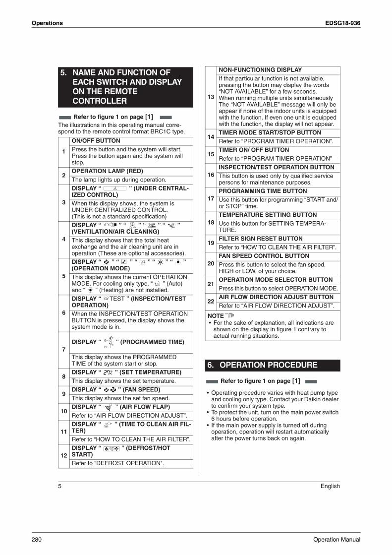
Operations EDSG18-936
5 English
The illustrations in this operating manual corre-spond to the remote control format BRC1C type.
• Operating procedure varies with heat pump type and cooling only type. Contact your Daikin dealer to confirm your system type.
• To protect the unit, turn on the main power switch 6 hours before operation.
• If the main power supply is turned off during operation, operation will restart automatically after the power turns back on again.
5. NAME AND FUNCTION OF EACH SWITCH AND DISPLAY ON THE REMOTE CONTROLLER
1
ON/OFF BUTTON Press the button and the system will start.Press the button again and the system will stop.
2OPERATION LAMP (RED)The lamp lights up during operation.
3
DISPLAY “ ” (UNDER CENTRAL-IZED CONTROL)When this display shows, the system is UNDER CENTRALIZED CONTROL.(This is not a standard specification)
4
DISPLAY “ ” “ ” “ ” “ ” (VENTILATION/AIR CLEANING)This display shows that the total heat exchange and the air cleaning unit are in operation (These are optional accessories).
5
DISPLAY “ ” “ ” “ ” “ ” “ ” (OPERATION MODE) This display shows the current OPERATION MODE. For cooling only type, “ ” (Auto) and “ ” (Heating) are not installed.
6
DISPLAY “ TEST ” (INSPECTION/TEST OPERATION)When the INSPECTION/TEST OPERATION BUTTON is pressed, the display shows the system mode is in.
7DISPLAY “ ” (PROGRAMMED TIME)
This display shows the PROGRAMMED TIME of the system start or stop.
8DISPLAY “ ” (SET TEMPERATURE)This display shows the set temperature.
9DISPLAY “ ” (FAN SPEED)This display shows the set fan speed.
10DISPLAY “ ” (AIR FLOW FLAP)Refer to “AIR FLOW DIRECTION ADJUST”.
11DISPLAY “ ” (TIME TO CLEAN AIR FIL-TER)Refer to “HOW TO CLEAN THE AIR FILTER”.
12DISPLAY “ ” (DEFROST/HOT START)Refer to “DEFROST OPERATION".
Refer to figure 1 on page [1]
13
NON-FUNCTIONING DISPLAYIf that particular function is not available, pressing the button may display the words “NOT AVAILABLE” for a few seconds.When running multiple units simultaneously The “NOT AVAILABLE” message will only be appear if none of the indoor units is equipped with the function. If even one unit is equipped with the function, the display will not appear.
14TIMER MODE START/STOP BUTTONRefer to “PROGRAM TIMER OPERATION”.
15TIMER ON/ OFF BUTTONRefer to “PROGRAM TIMER OPERATION”
16INSPECTION/TEST OPERATION BUTTONThis button is used only by qualified service persons for maintenance purposes.
17PROGRAMMING TIME BUTTONUse this button for programming “START and/or STOP” time.
18TEMPERATURE SETTING BUTTONUse this button for SETTING TEMPERA-TURE.
19FILTER SIGN RESET BUTTONRefer to “HOW TO CLEAN THE AIR FILTER”.
20FAN SPEED CONTROL BUTTONPress this button to select the fan speed,HIGH or LOW, of your choice.
21OPERATION MODE SELECTOR BUTTONPress this button to select OPERATION MODE.
22AIR FLOW DIRECTION ADJUST BUTTONRefer to “AIR FLOW DIRECTION ADJUST”.
NOTE• For the sake of explanation, all indications are
shown on the display in figure 1 contrary to actual running situations.
6. OPERATION PROCEDURE
Refer to figure 1 on page [1]
280 Operation Manual

EDSG18-936 Operations
4
English 6
Operate in the following order.
Press OPERATION MODE SELECTOR but-ton several times and select the OPERA-TION MODE of your choice as follows.
COOLING OPERATION ........................ “ ”HEATING OPERATION ......................... “ ”AUTOMATIC OPERATION .................... “ ”
• In this operation mode,COOL/HEAT changeover is automatically conducted.
FAN OPERATION ................................. “ ”DRY OPERATION ................................. “ ”
• The function of this program is to decrease the humidity in your room with the minimum temperature decrease.
• Micro computer automatically determines TEMPERATURE and FAN SPEED.
• This system dose not go into operation if the room temperature is below 16˚C.
• For cooling only type, “ COOLING ”, “ FAN ” and “ DRY ” operation are able to select.
Press ON/OFF buttonOPERATION lamp lights up or goes off and the sys-tem starts or stops OPERATION.
[EXPLANATION OF HEATING OPERATION]
(1) DEFROST OPERATION• As the frost on the coil of an outdoor unit
increase, heating effect decreases and the system goes into DEFROST OPERATION.
• The indoor unit fan stops and the remote con-troller display shows“ ”.
• After 6 to 8 minutes (maximum 10 minutes) of DEFROST OPERATION, the system returns to HEATING OPERATION.
(2) HOT START• In order to prevent cold air from blowing out of
an indoor unit at the start of heating operation, the indoor fan is automatically stopped. The display of the remote controller shows “ ” (DEFROST/HOT START).
(3) OPERATION START• For ordinary heating, it will take longer for the
room temperature to reach the set tempera-ture than with cooling. We therefore recom-mend starting the unit ahead of time using the timer operation.
Regarding outside air temperature and heating capacity• The heating capacity of the air conditioner
declines as the outside air temperature falls.In such a case, use the air conditioner in combi-nation with other heating systems.
• A warm air circulating system is employed, and therefore it takes some time until the entire room is warmed up after the start of operation.
• An indoor fan runs to discharge a gentle wind automatically until the temperature inside the air conditioner reaches a certain level. At this time, the remote controller displays“ ”. Leave it as it stands and wait for a while.
• When the warm air stays under the ceiling and your feet are cold, we recommend that you use a circulator (a fan to circulate the air inside the room). For details,consult your dealer.
For programming TEMPERATURE, FAN SPEED and AIR FLOW DIRECTION, follow the procedure shown below.
Press TEMPERATURE SETTING button and program the setting temperature.
• The setting is impossible for fan operation.
NOTE• The setting temperature range of the remote con-
troller is 16˚C to 32˚C.
Press FAN SPEED CONTROL button.High or Low fan speed can be selected.Micro computer may sometimes control the fan speed in order to protect the unit.
COOLING, HEATING, AUTOMATIC, FAN, AND PROGRAM DRY OPERATION
OPERATION MODE SELEC-TOR1
Refer to figure 3 on page [1]
ON/OFF2
ADJUSTMENT
Each time this button is pressed,setting temperature rises 1˚C.
Each time this button is pressed, set-ting temperature lowers 1˚C.
TEMPERATURE SETTING
FAN SPEED CONTROL
Operation Manual 281

Operations EDSG18-936
7 English
Press the AIR FLOW DIRECTION ADJUST button to adjust the air flow angle.
• The movable limit of the flap is changeable.Contact your Daikin dealer for details.
Press the AIR FLOW DIRECTION ADJUST button to select the air direction as following.
The AIR FLOW FLAP display swings as shown left and the air flow direction continuously varies. (Automatic swing set-ting)
Press AIR FLOW DIRECTION ADJUST button to select the air direction of your choice.
The AIR FLOW FLAP display stops swinging and the air flow direction is fixed (Fixed air flow direction setting).
MOVEMENT OF THE AIR FLOW FLAPFor the following conditions, micro computer con-trols the air flow direction so it may be different from the display.
Operation mode includes automatic operation.
ATTENTION:• The movable limit of the flap is changeable. Con-
tact your Daikin dealer for details.• Avoid operating in the horizontal direction “ ”
which may cause dew or dust to settle on ceiling.
Operate in the following order.• The timer is operated in the following two ways.
Programming the stop time ( ) .... The sys-tem stops operating after the set time has elapsed.
Programming the start time ( ) .... The sys-tem starts operating after the set time has elapsed.
• The timer can be programmed a maximum of 72 hours.
• The start and the stop time can be simulta-neously programmed.
Press the TIMER MODE START/STOP but-ton several times and select the mode on the display.The display flashes.For setting the timer stop .... “ ”For setting the timer start .... “ ”
Press the PROGRAMMING TIME button and set the time for stopping or starting the sys-tem.
When this button is pressed, the time advances by 1 hour.
When this button is pressed, the time goes backward by 1 hour.
Press the TIMER ON/OFF button.The timer setting procedure ends. The display “ or ” changes from flash-ing light to a constant light.
For example:When the timer is programmed to stop the system after 3 hours and start the system after 4 hours, the system will stop after 3 hours and then 1 hour later the system will start.
NOTE• When setting the timer Off and On at the same
time, repeat the above procedure from 1 to 3 once again.
• After the timer is programmed, the display shows the remaining time.
• Press the TIMER ON/OFF button once again to cancel programming. The display vanishes.
Operation mode Heating
Operation condition
• When starting operation• When room temperature is higher
than the set temperature• At defrost operation
(Air is blown horizontally to prevent the cool air from being blown directly onto anyone in the room.)
PROGRAM TIMER OPERATION
AIR FLOW DIRECTION ADJUST
Up and down adjustment
swing
TIMER MODE START/STOP1
PROGRAMMING TIME2
TIMER ON/OFF3
Refer to figure 4 on page [1]
282 Operation Manual

EDSG18-936 Operations
4
English 8
Observe the following precautions to ensure the system operates.• Adjust the room temperature properly for a com-
fortable environment. Avoid excessive heating or cooling.
• Prevent direct sunlight from entering a room dur-ing cooling operation by using curtains or blinds.
• Ventilate the room regularly.Using the unit for long periods of time requires attentive ventilation of the room.
• Do not place items that might be damaged by water under the indoor unit.Water may condensate and drip if the humidity reaches 80% or if the drain exit gets clogged.
• Keep doors and windows closed. If the doors and windows remain open, room air will flow out and cause to decrease the effect of cooling and heat-ing.
• Do not place other heaters directly below the indoor unit.They may deform due to the heat.
• Never place objects near the air inlet and the air outlet of the unit. It may cause deterioration in the effect or stop in the operation.
• Turn off the main power supply switch when it is not used for long periods of time. When the main power switch is turned on, some watts of electric-ity is being used even if the system is not operat-ing. Turn off the main power supply switch for saving energy. When reoperating, turn on the main power supply switch 6hours before opera-tion for smooth running (Refer to MAINTE-NANCE).
• When the display shows “ ” (TIME TO CLEAN AIR FILTER), ask a qualified service per-son to clean the filters (Refer to MAINTE-NANCE).
• Fully use the function of air flow direction adjust.Cold air gathers on the floor, and warm air gath-ers in the ceiling.Set the air flow direction parallel during cooling or dry operation, and set it downwards during heat-ing operation.Do not let the air blow directly to a person.
• It takes time for the room temperature to reach the set temperature.We recommend starting the operation in advance using timer operation.
ONLY A QUALIFIED SERVICE PERSON IS ALLOWED TO PERFORM MAINTENANCE
WARNING• Before touching any of connection wirings, be
sure to turn off all power supply switches.• Contact professional personnel about attach-
ment of accessories and be sure to use only accessories specified by the manufacturer.If a defect results from your own workmanship, it may result in water leaks, electric shock or fire.
CAUTION• Before cleaning, be sure to stop unit opera-
tion, turn the breaker off or remove the power cord.Otherwise, an electric shock and injury may result.
• Do not wash the air conditioner with water, as this may result in electric shocks or fire.
• Consult your dealer regarding cleaning the inside of the air conditioner.Improper cleaning may cause breakage of plastic parts, water leakage and other damage as well as electric shocks.Take care of scaffolding and exercise caution when working high above ground level.
HOW TO CLEAN THE AIR FILTERClean the air filter when the display shows “ ” (TIME TO CLEAN AIR FILTER).
It will display that it will operate for a set amount of time.Increase the frequency of cleaning if the unit is installed in a room where the air is extremely con-taminated.If the dirt becomes impossible to clean, change the air filter (Air filter for exchange is optional)
1. Open the suction grille.Push it downward slowly while pressing horizon-tally the buttons provided on two spots.(Follow the same procedure for closing.)
7. OPTIMUM OPERATION 8. MAINTENANCE(FOR SERVICE PERSONNEL)
Operation Manual 283

Operations EDSG18-936
9 English
2. Detach the air filter.Pull the hook of the air filter out diagonally down-ward, and remove the filter.
3. Clean the air filter.Use vacuum cleaner A) or wash the air filter with water B).A) Using a vacuum cleaner
B) Washing with waterWhen the air filter is very dirty, use soft brush and neutral detergent.
Remove water and dry in the shade.
NOTE• Do not wash the air conditioner with hot water of
more than 50˚C, as doing so may result in discol-oration and/or deformation.
• Do not expose it to fire, as doing so may result in burning.
4. Fix the air filter.(1) Hook the air filter to a protrusion on the suc-
tion grille.(2) Push the lower part of the air filter onto the
protrusion at the lower part of the suction grille, and fix the air filter there.
5. Shut the suction grille.Refer to item No.1.
6. After turning on the power, press FILTER SIGN RESET button.The “TIME TO CLEAN AIR FILTER” display van-ishes.
HOW TO CLEAN AIR OUTLET AND OUT-SIDE PANELS• Clean with soft cloth.• When it is difficult to remove stains, use water or
neutral detergent.
• When the flap is extremely contaminated, remove it as below and clean or exchange it.(For changing the flap, please contact your dealer.)
NOTE• Do not use gasoline, benzene, thinner, polishing
powder, liquid insecticide. It may cause discolor-ing or warping.
• Do not let the indoor unit get wet. It may cause an electric shock or a fire.
• Do not scrub firmly when washing the blade with water.The surface sealing may peel off.
• Do not use water or air of 50˚C or higher for cleaning air filters and outside panels.
HOW TO CLEAN THE SUCTION GRILLE1. Open the suction grille.
Push it downward slowly while pressing horizon-tally the buttons provided on two spots. (Follow the same procedure for closing.)
2. Detach the suction grille.Open the suction grille 45 degrees and lift it upward.
3. Detach the air filter.Refer to “HOW TO CLEAN THE AIR FILTER-item No.2”.
4. Clean the suction grille.Wash with a soft bristle brush and neutral detergent or water, and dry throughly.• When very grimyDirectly apply the type of detergent used for cleaning ventilation fans or ovens, wait 10 minutes, and then rinse with water.
5. Fix the air filter.Refer to “HOW TO CLEAN THE AIR FILTER-item No.4”.
284 Operation Manual

EDSG18-936 Operations
4
English 10
6. Fix the suction grille.Refer to item No. 2.
7. Shut the suction grille.Refer to item No. 1.
START UP AFTER A LONG STOPConfirm the following• Check that the air inlet and outlet are not
blocked. Remove any obstacle.• Check if the earth is connected.
Might there be a broken wire somewhere?Contact your dealer if there are any problems.
Clean the air filter and outside panels• After cleaning the air filter, make sure to attach it.
Turn on the main power supply switch• The display on the remote controller will be
shown when the power is turned on.•
•
To protect the unit, turn on the main power switch at least 6 hours before operation.
WHAT TO DO WHEN STOPPING THE SYS-TEM FOR A LONG PERIODTurn on FAN OPERATION for a half day and dry the unit.
Refer to “6.OPERATION PROCEDURE”.
Cut off the power supply.• When the main power switch is turned on, some
watts of electricity is being used even if the sys-tem is not operating.Turn off the main power supply switch for saving energy.
• The display on the remote controller will vanish when the main power switch is turned off.
Clean the air filter and the exterior.• Be sure to replace the air filter to its original place
after cleaning. Refer to “MAINTENANCE”.
The following symptoms do not indicate air condi-tioner malfunction
I. THE SYSTEM DOES NOT OPERATE• The system does not restart immediately
after the ON/OFF button is pressed.If the OPERATION lamp lights, the system is in normal condition.It does not restart immediately because a safety device operates to prevent overload of the sys-tem. After 3 minutes, the system will turn on again automatically.
• The system does not restart immediately when TEMPERATURE SETTING button is returned to the former position after pushing the button.If the OPERATION lamp lights, the system is in normal condition.
It does not restart immediately because a safety device operates to prevent overload of the sys-tem. After 3 minutes, the system will turn on again automatically.
• The system does not start when the display shows “ ” (UNDER CENTRALIZED CONTROL) and it flashes for few seconds after pressing an operation button.This is because the system is under centralized control. Flashes on the display indicates that the system cannot be controlled by the remote con-troller.
• The system does not start immediately after the power supply is turned on.Wait one minute until the micro computer is pre-pared for operation.
• The outdoor unit is stoppedThis is because the room temprerature has reached the set temprerature. The indoor unit switches to fan operation.
II. The display shows “ ” (UNDER CEN-TRALIZED CONTROL) and the unit operates in a mode different to what is shown on the remote controller display.When using a unit in a multi system, the opera-tion condition of that unit is controlled by a micro computer as described below, according to the operation condition of other indoor units con-nected to the system.
• If the operation mode does not match other indoor units that are already running, the indoor unit will assume the STANDBY state (the fan is stopped and the air flow flap is positioned hori-zontally).If HEATING mode is set together with COOLING, DRY or FAN mode, the above mentioned condi-tion will occur.
NOTE• Normally, the operation mode in the room where
the unit is first run is given priority, but the follow-ing situations are exceptions, so please keep this in mind.a. If the operation mode of the first room is FAN
Mode, then using Heating Mode in any room after this will give priority to heating. In this sit-uation, the air conditioner running in FAN Mode will go on standby.
b. With the Priority Room Setting active.Contact your Daikin dealer for the operation that corresponds to your system.
• If the total capacity of operating indoor units exceeds the limit, the indoor unit will assume the STANDBY state (FAN and AIR FLOW DIREC-TION will be left as set). (This only applies to cooling only type.)
• If another indoor unit commences a HEATING operation after this indoor unit is running in COOLING mode, this indoor unit may switch to DRY operation (fan on low, air flow flap set at hor-izontal).
9. NOT MALFUNCTION OF THE AIR CONDITIONER
Operation Manual 285

Operations EDSG18-936
11 English
III. The fan speed is different from the setting.• Pressing the fan speed control button does
not change the fan speed.When the room temperature reaches the set temperature in heating mode, the power supply from the outdoor unit is stopped and the indoor unit will operate on the low fan setting. (If using the multi system, the fan will alternate between off and low.)This is to prevent the cool air from being blown directly onto anyone in the room.
IV. AIR BLOW DIRECTION IS NOT AS SPECI-FIED.
• Actual air blow direction is not as shown on the remote contoller.
• Automatic swing setting does not work.Refer to “AIR FLOW DIRECTION ADJUST.”
V. WHITE MIST COMES OUT OF A UNIT• When humidity is high during cooling opera-
tion (In oily or dusty places)If the inside of an indoor unit is extremely con-taminated, the temperature distribution inside a room becomes uneven. It is necessary to clean the inside of the indoor unit. Ask your Daikin dealer for details on cleaning the unit. This oper-ation requires a qualified service person.
• When the system is changed over to HEATING OPERATION after DEFROST OPERATION.Moisture generated by DEFROST becomes steam and exists.
VI.NOISE OF AIR CONDITIONERS• A ringing sound after the unit is started.
This sound is generated by the temperature reg-ulator working. It will quiet down after about a minute.
• A continuous flow “Shuh” sound is heard when the systems is in COOLING or DEFROST OPERATION.This is the sound of refrigerant gas flowing through both indoor and outdoor units.
• A “Shuh” sound which is heard at the start or immediately after the stop of operation or which is heard at the start or immediately after the stop of DEFROST OPERATION. This is the noise of refrigerant caused by flow stop and flow change.
• A continuous flowing sound "Shah"or a trick-ling sound "Jyuru Jyuru"are heard when the system is in COOLING OPERATION or at a stop.The noise is heard when the drain pump is in operation.
• A “Pishi-pishi” squeaking sound is heard when the system is in operation or after the stop of operation.Expansion and contraction of plastic parts caused by temperature change makes this noise.
VII.DUST FROM THE UNITS• Dust may blow out from the unit after starting
operation from long resting time.Dust absorbed by the unit blows out.
VIII.THE UNITS GIVE OFF ODORSThe unit absorbs the smell of rooms, furniture, cigarettes, etc., and then emits them.
IX.THE LIQUID CRYSTAL OF THE REMOTE CONTROLLER SHOW “ ”
• It happens immediately after the main power supply switch is turned on.This shows that the remote controller is in nor-mal condition.This continues temporary.
X. THE ROOM TEMPERATURE DOES NOT DROP• The air conditioner is in program dry opera-
tion.The air conditioner in program dry operation does not drop the room temperature as much as possible. See page 5-6 “OPERATION PROCE-DURE”.
I. If one of the following malfunctions occurs, take the measures shown below and contact your Daikin dealer.
The system must be repaired by a qualified service person.
WARNINGWhen the air conditioner is in abnormal con-ditions (smell of something burning, etc), unplug the power cord from the outlet, and contact your dealerContinued operation under such circumstances may result in a failure, electric shock, and fire.
• If a safety device such as a fuse, a breaker or an earth leakage breaker frequently actuates; Measure: Do not turn on the main power switch.
• If the ON/OFF switch does not properly work;Measure: Turn off the main power switch.
• If water leaks from unit.Measure: Stop the operation.
• If the display “ ” (INSPECTION), “UNIT No.”, and the OPERATION lamp flash and the “MAL-FUNCTION CODE” appears.
Measure: Notify and inform the model name and what the malfunction code indi-cates to your Daikin dealer.
10. TROUBLE SHOOTING
OPERATION lamp
INSPECTION display
MALFUNCTION CODE
INDOOR UNIT No. in whicha malfunction occurs
UNIT No.
C L H
286 Operation Manual

EDSG18-936 Operations
4
English 12
II. If the system does not properly operate except for the above mentioned case, and none of the above mentioned malfunctions is evident, investigate the system according to the following procedures.
1. If the system does not operate at all.• Check if there is a power failure.
Wait until power is restored. If power failure occurs during operation, the system automati-cally restarts immediately after the power supply recovers.
• Check if no fuse has blown.Turn off the power supply.
• Check if the breaker is blown.Turn the power on with the breaker switch in the off position.Do not turn the power on with the breaker switch in the trip position.(Contact your dealer.)
2. If the system stops operating after operating the system.
• Check if the air inlet or outlet of outdoor or indoor unit is blocked by obstacles.Remove the obstacle and make it well-ventilated.
• Check if the air filter is clogged.Ask a qualified service person to clean the air fil-ters (Refer to MAINTENANCE).
3. The system operates but it does not suffi-ciently cool or heat.
• If the air inlet or outlet of the indoor or the outdoor unit is blocked with obstacles.Remove the obstacle and make it well-ventilated.
• If the air filter is clogged.Ask a qualified service person to clean the air fil-ters (Refer to MAINTENANCE).
• If the set temperature is not proper (Refer to ADJUSTMENT).
• If the FAN SPEED button is set to LOW SPEED (Refer to ADJUSTMENT).
• If the air flow angle is not proper (Refer to AIR FLOW DIRECTION ADJUST).
• If the doors or the windows are open. Shut doors or windows to prevent wind from com-ing in.
• If direct sunlight enters the room (when cooling).Use curtains or blinds.
• When there are too many inhabitants in the room (when cooling).Cooling effect decreases if heat gain of the room is too large.
• If the heat source of the room is excessive (when cooling).Cooling effect decreases if heat gain of the room is too large.
ON
OFF
Trip positionSwitch
Breaker
3P184442-4D
Operation Manual 287
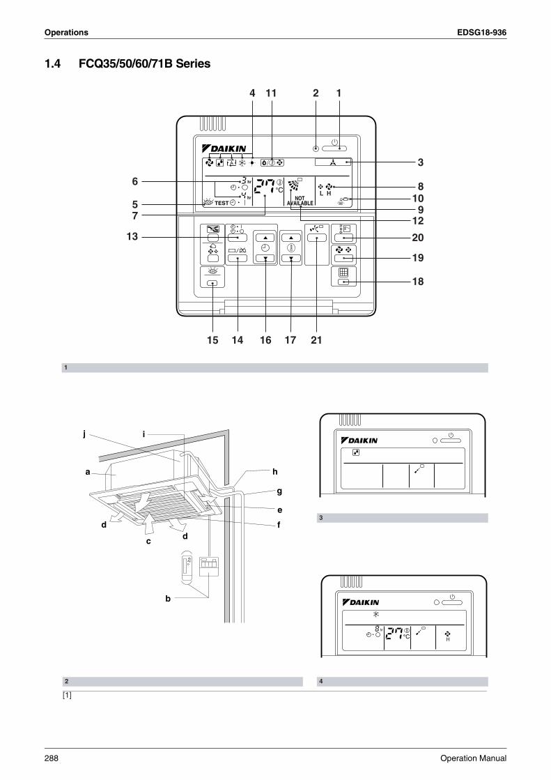
Operations EDSG18-936
1.4 FCQ35/50/60/71B Series
[1]
1
3
42
2
910
3
14
5
6
7
13
1415 16 17
18
19
20
21
11
8
12
a
b
c dd
e
f
g
h
j i
Chr
H
Chr
hrTEST
NOTAVAILABLE
L H
288 Operation Manual

EDSG18-936 Operations
4
This operation manual is for the system with stan-dard control. Before initiating operation, contact your Daikin dealer for the operation that corre-sponds to your system.
NOTE• If the unit you purchased is controlled by a wire-
less remote controller, also refer to the wireless remote controller’s operation manual.
If your installation has a customized control system, ask your Daikin dealer for the operation that corre-sponds to your system.
• Heat pump typeThis system provides cooling, heating, automatic, program dry, and fan operation modes.
• Cooling only typeThis system provides cooling, program dry, and fan operation modes.
1. WHAT TO DO BEFORE OPERATION
PRECAUTIONS FOR GROUP CONTROL SYSTEM OR TWO REMOTE CONTROL-LERS CONTROL SYSTEM
This system provides two other control systems beside individual control (one remote controller con-trols one indoor unit) system. Confirm the following if your unit is of the following control system type.
• Group control systemOne remote controller controls up to 16 indoor units.All indoor units are equally set.
• Two remote controllers control systemTwo remote controllers control one indoor unit (In case of group control system, one group of indoor units)The unit is individually operated.
NOTE• Contact your Daikin dealer in case of changing
the combination or setting of group control and two remote controllers control system.
Refer to figure 2 on page [1]
Names and functions of parts
a Indoor unit
b Remote controller
c Inlet air
d Discharge air
e Air outlet
f Air flow flap (at air outlet)
g Refrigerant piping, connection electric wire
h Drain pipe
iAir inletThe built-in air filter removes dust and dirt.
jDrain pumping out device(built-in)Condensate removed from the room during cooling.
Operation Manual 289

Operations EDSG18-936
We recommend that you read this instruction man-ual carefully before use to gain full advantage of the function of the air conditioner, and to avoid malfunc-tion due to mishandling.This air conditioner comes under the term “appli-ances not accessible to the general public”. • The precautions described below are WARN-
ING and CAUTION. These are very important precautions concerning safety. Be sure to observe all of them without fail.
WARNING ...These are the matters with possi-bilities leading to serious conse-quences such as death or serious injury due to erroneous handling.
CAUTION ....These are the matters with possi-bilities leading to injury or material damage due to erroneous han-dling including probabilities lead-ing to serious consequences in some cases.
• After reading, keep this manual at a place where any user can read at any time. Further-more, make certain that this operation manual is handed to a new user when he takes over the operation.
WARNINGAvoid exposure of your body directly to the cold air for a long time, or avoid excessive exposure of your body to the cold air.Otherwise, your physical condition may be dete-riorated and/or your health may be ruined.When the air conditioner is in abnormal con-ditions (smell of something burning, etc), turn off power, and contact the dealer where you purchased the air conditioner.Continued operation under such circumstances may result in a failure, electric shock, and fire.Ask your dealer for installation of the air con-ditioner.Incomplete installation performed by yourself may result in a water leakage, electric shock, and fire.Ask your dealer for improvement, repair, and maintenance.Incomplete improvement, repair, and mainte-nance may result in a water leakage, electric shock, and fire.Do not insert your finger, a stick, etc., into the air inlet, outlet, and fan blades.A fan in high-speed running may result in injury.The refrigerant in the air conditioner is safe and normally does not leak. If the refrigerant leaks inside the room, the contact with a fire of a burner, a heater or a cooker may result in a harmful gas.Do not use the air conditioner until when a ser-vice person confirms to finish repairing the por-tion where the refrigerant leaks.
2. SAFETY CONSIDERATIONS For refrigerant leakage, consult your dealer.When the air conditioner is to be installed in a small room, it is necessary to take proper mea-sures so that the amount of any leaked refriger-ant does not exceed the limiting concentration even when it leaks. If the refrigerant leaks exceeding the level of limiting concentration, an oxygen deficiency accident may happen.For installation of separately sold compo-nent parts, ask a specialist.Be sure to use the separately sold component parts designated by our company.Incomplete installation performed by yourself may result in a water leakage, electric shock, and fire.Ask your dealer to move and reinstall the air conditioner.Incomplete installation may result in a water leakage, electric shock, and fire.Do not use any fuse with improper capacity.The use of a piece of wire and whatnot may result in a failure and fire.
CAUTIONDo not use the air conditioner for other pur-poses.Do not use the air conditioner for a special appli-cation such as the storage of foods, animals and plants, precision machines, and art objects as otherwise the deterioration of quality may result.Do not remove the air outlet of the ou tdoor unit.The fan may get exposed and result in injury.Do not place items that might be damaged by water under the indoor unit.Water may condensate and drip if the humidity reaches 80% or if the drain exit gets clogged.When the air conditioner is used in combina-tion with burners or heaters, perform suffi-cient ventilation.Insufficient ventilation may result in an oxygen deficiency accident.Check and make sure that foundation blocks are not damaged after a long use.If they are left in a damaged condition, the unit may fall and result in injury.Neither place a flammable spray bottle near the air conditioner nor perform spraying.Doing so may result in a fire.To clean the air conditioner, stop operation, and unplug the power cord from the outlet.Otherwise, an electric shock and injury may result.Do not operate the air conditioner with a wet hand.An electric shock may result.Do not place a burner or heater at a place directly exposed to the wind from the air con-ditioner.Incomplete combustion of the burner or heater may result.Do not allow a child to mount on the outdoor unit or avoid placing any object on it.Falling or tumbling may result in injury.
290 Operation Manual

EDSG18-936 Operations
4
Never expose little children, plants or ani-mals directly to the air flow.Adverse influence to little children, plants or animals may result.Do not wash the air conditioner with water.Electric shock or fire may result.Do not install the air conditioner at any place where flammable gas may leak out.If the gas leaks out and stays around the air con-ditioner, a fire may break out.Be sure to install an earth leakage breaker.Unless it is installed, an electric shock or fire may result.Be sure the air conditioner is electrically grounded.Do not connect the grounding conductor to a gas pipe, water pipe, lightning arrester, and the grounding conductor for a telephone. Imperfect grounding work may result in an elec-tric shock.Execute complete drain piping for perfect drainage.Incomplete piping may result in a water leakage.The appliance is not intended for use by young children or infirm persons without supervision.Young children should be supervised to ensure that they do not play with the appliance.
If the temperature or the humidity is beyond the fol-lowing conditions, safety devices may work and the air conditioner may not operate, or sometimes, water may drop from the indoor unit.
COOLING ONLY TYPE
HEAT PUMP TYPE
D B: Dry bulb temperatureWB: Wet bulb temperature
The setting temperature range of the remote con-troller is 16°C to 32°C.
3. OPERATION RANGE
TEMPERATURE[°C]
OUTDOOR INDOOR
– 5 to 46(DB) 21 to 32(DB)/14 to 23(WB)
OPERATIONTEMPERATURE[°C]
OUTDOOR INDOOR
COOLING – 5 to 46(DB) 21 to 32(DB)/14 to 23(WB)
HEATING –14 to 21(DB)/–15 to 15.5(WB) 14 to 28(DB)
Regarding places for installation• Is the air conditioner installed at a well-venti-
lated place where there are no obstacles around?
• Do not use the air conditioner in the following places.a. Filled with much mineral oil such as cutting oilb. Where there is much salt such as a beach areac. Where sulfured gas exists such as a hot-spring
resortd. Where there are considerable voltage fluctua-
tions such as a factory or plante. Vehicles and vesselsf. Where there is much spray of oil and vapor
such as a cookery, etc.g. Where there are machines generating electro-
magnetic wavesh. Filled with acid and/or alkaline steam or vapor
• Is a snow protection measure taken?For details, consult your dealer.
Regarding wiring• All wiring must be performed by an authorized
electrician.To do wiring, ask your dealer. Never do it by your-self.
• Make sure that a separate power supply cir-cuit is provided for this air conditioner and that all electrical work is carried out by quali-fied personnel according to local laws and regulations.
Pay attention to running noises, too• Are the following places selected?
a. A place that can sufficiently withstand the weight of the air conditioner with less running noises and vibrations.
b. A place where the hot wind discharged from the air outlet of the outdoor unit and the running noises.
• Are you sure that there are no obstacles near the air outlet of the outdoor unit?Such obstacles may result in declined perfor-mance and increased running noises.
• If abnormal noises occur in use, consult your dealer.
Regarding drainage of drain piping• Is the drain piping executed to perform com-
plete drainage?If proper drainage is not carried out from the out-door drain pipes during air-conditioning operation, chances are that dust and dirt are clogged in the pipe. This may result in a water leakage from the indoor unit. Under such circumstances, stop the operation of the air conditioner, and then consult your dealer or our service station.
4. INSTALLATION SITE
Operation Manual 291

Operations EDSG18-936
Refer to figure 1 on page [1] The illustrations in this operating manual corre-spond to the remote control format BRC1C type. Although the display and shape of the buttons on the BRC1B type are slightly different, they may be operated in the same manner.
5. NAME AND FUNCTION OF EACH SWITCH AND DISPLAY ON THE REMOTE CONTROLLER
1
ON/OFF BUTTONPress the button and the system will start. Press the button again and the system will stop.
2OPERATION LAMP (RED)The lamp lights up during operation.
3
DISPLAY “ ” (UNDER CENTRAL-IZED CONTROL)When this display shows, the system is UNDER CENTRALIZED CONTROL.
4
DISPLAY “ ” “ ” “ ” “ ” “ ” (OPERATION MODE)This display shows the current OPERATION MODE. For cooling only type, “ ” (Auto) and “ ” (Heating) are not installed.
5
DISPLAY “ TEST” (INSPECTION/TEST OPERATION)When the INSPECTION/TEST OPERATION BUTTON is pressed, the display shows the system mode is in.
6DISPLAY “ ” (PROGRAMMED TIME)
This display shows the PROGRAMMED TIME of the system start or stop.
7DISPLAY “ ” (SET TEMPERATURE)This display shows the set temperature.
8DISPLAY “ ” (FAN SPEED)This display shows the set fan speed.
9DISPLAY “ ” (AIR FLOW FLAP)Refer to “AIR FLOW DIRECTION ADJUST”.
10DISPLAY “ ” (TIME TO CLEAN AIR FILTER)Refer to “HOW TO CLEAN THE AIR FILTER”.
11DISPLAY “ ” (DEFROST)Refer to “DEFROST OPERATION”.
12
NON-FUNCTIONING DISPLAYIf that particular function is not available, pressing the button may display the words “NOT AVAILABLE” for a few seconds.
13TIMER MODE START/STOP BUTTONRefer to “PROGRAM TIMER OPERATION”.
hr
hr
C
Refer to figure 1 on page [1]
• Operating procedure varies with heat pump type and cooling only type. Contact your Daikin dealer to confirm your system type.
• To protect the unit, turn on the main power switch 6 hours before operation.
• If the main power supply is turned off during oper-ation, operation will restart automatically after the power turns back on again.
Operate in the following order.
OPERATION MODE SELEC-TOR
Press OPERATION MODE SELECTOR but-ton several times and select the OPERA-TION MODE of your choice as follows.
14TIMER ON/OFF BUTTONRefer to “PROGRAM TIMER OPERATION”.
15INSPECTION/TEST OPERATION BUTTONThis button is used only by qualified service persons for maintenance purposes.
16PROGRAMMING TIME BUTTONUse this button for programming “START and/or STOP” time.
17TEMPERATURE SETTING BUTTONUse this button for SETTING TEMPERA-TURE.
18FILTER SIGN RESET BUTTONRefer to “HOW TO CLEAN THE AIR FILTER”.
19FAN SPEED CONTROL BUTTONPress this button to select the fan speed, HIGH or LOW, of your choice.
20OPERATION MODE SELECTOR BUTTONPress this button to select OPERATION MODE.
21AIR FLOW DIRECTION ADJUST BUTTONRefer to “AIR FLOW DIRECTION ADJUST”.
NOTE• For the sake of explanation, all indications are
shown on the display in figure 1 contrary to actual running situations.
6. OPERATION PROCEDURE
COOLING, HEATING, AUTOMATIC, FAN, AND PROGRAM DRY OPERATION
1
292 Operation Manual

EDSG18-936 Operations
4
COOLING OPERATION ................................ “ ”HEATING OPERATION.................................“ ”AUTOMATIC OPERATION............................“ ”
• In this operation mode, COOL/HEAT changeover is automatically conducted.
FAN OPERATION..........................................“ ”DRY OPERATION .........................................“ ”
The function of this program is to decrease the humidity in your room with the minimum tem-perature decrease.
• Micro computer automatically determines TEMPERATURE and FAN SPEED.
• This system does not go into operation if the room temperature is below 16°C.
Refer to figure 3 on page [1]
• For cooling only type, “COOLING” , “FAN” and “DRY” operation are able to select.
ON/OFF
Press ON/OFF buttonOPERATION lamp lights up or goes off and the sys-tem starts or stops OPERATION.
[EXPLANATION OF HEATING OPERATION]
DEFROST OPERATION
• As the frost on the coil of an outdoor unit increase, heating effect decreases and the system goes into DEFROST OPERATION.
• The indoor unit fan stops and the remote control-ler display shows “ ”.
• After 6 to 8 minutes (maximum 10 minutes) of DEFROST OPERATION, the system returns to HEATING OPERATION.
Regarding outside air temperature and heat-ing capacity• The heating capacity of the air conditioner
declines as the outside air temperature falls. In such a case, use the air conditioner in combina-tion with other heating systems.
• A warm air circulating system is employed, and therefore it takes some time until the entire room is warmed up after the start of operation.
• An indoor fan runs to discharge a gentle wind automatically until the temperature inside the air conditioner reaches a certain level. At this time, the remote controller displays “ ”. Leave it as it stands and wait for a while.
• When the warm air stays under the ceiling and your feet are cold, we recommend that you use a circulator (a fan to circulate the air inside the room). For details, consult your dealer.
2
For programming TEMPERATURE, FAN SPEED and AIR FLOW DIRECTION, follow the procedure shown below.
TEMPERATURE SETTING
Press TEMPERATURE SETTING button and program the setting temperature.
Each time this button is pressed, setting temperature rises 1°C.
Each time this button is pressed, setting temperature lowers 1°C.
• The setting is impossible for fan operation.
NOTE• The setting temperature range of the remote con-
troller is 16°C to 32°C.
FAN SPEED CONTROL
Press FAN SPEED CONTROL button.High or Low fan speed can be selected.The microchip may sometimes control the fan speed in order to protect the unit.
AIR FLOW DIRECTION ADJUST
Press the AIR FLOW DIRECTION button to adjust the air flow angle.
The movable limit of the flap is changeable. Contact your Daikin dealer for details.
ADJUSTMENT
Up and down adjustment
Operation Manual 293

Operations EDSG18-936
Press the AIR FLOW DIRECTION ADJUST button to select the air direction as shown below.
The AIR FLOW FLAP display swings as shown below and the air flow direction continu-ously varies. (Automatic swing setting)
Press AIR FLOW DIRECTION ADJUST button to select the air direction of your choice.
The AIR FLOW FLAP display stops swinging and the air flow direction is fixed (Fixed air flow direction setting).
MOVEMENT OF THE AIR FLOW FLAP
For the following conditions, micro computer con-trols the air flow direction so it may be different from the display.
Operation mode includes automatic operation.
Operate in the following order.• The timer is operated in the following two ways.• Programming the stop time ( ) .... The sys-
tem stops operating after the set time has elapsed.
• Programming the start time ( ) .... The sys-tem starts operating after the set time has elapsed.
• The timer can be programmed a maximum of 72 hours.
• The start and the stop time can be simultaneously programmed.
Operation mode
Cooling Heating
Operation condition
• When room temperature is lower than the set temperature
• When operating continuously at horizontal air flow direction
• When room temperature is higher than the set temperature
• At defrost opera-tion
PROGRAM TIMER OPERATION
swing
TIMER MODE START/STOP
Press the TIMER MODE START/STOP button several times and select the mode on the display.The display flashes.For setting the timer stop .... “ ”For setting the timer start .... “ ”
PROGRAMMING TIME
Press the PROGRAMMING TIME button and set the time for stopping or starting the sys-tem.
When this button is pressed, the time advances by 1 hour.
When this button is pressed, the time goes backward by 1 hour.
TIMER ON/OFF
Press the TIMER ON/OFF button.The timer setting procedure ends. The display “ or ” changes from flash-ing light to a constant light.
Refer to figure 4 on page [1]
NOTE• When setting the timer Off and On at the same
time, repeat the above procedure from to once again.
When the timer is programmed to stop the system after 3 hours and start the system after 4 hours, the system will stop after 3 hours and then 1 hour later the system will start.
• After the timer is programmed, the display shows the remaining time.
• Press the TIMER ON/OFF button once again to cancel programming. The display vanishes.
Observe the following precautions to ensure the system operates.• Adjust the room temperature properly for a com-
fortable environment. Avoid excessive heating or cooling.
• Prevent direct sunlight from entering a room dur-ing cooling operation by using curtains or blinds.
7. OPTIMUM OPERATION
1
2
3
1 3
294 Operation Manual

EDSG18-936 Operations
4
• Ventilate the room regularly.Using the unit for long periods of time requires attentive ventilation of the room.
• Keep doors and windows closed. If the doors and windows remain open, room air will flow out and cause to decrease the effect of cooling and heat-ing.
• Do not place other heaters directly below the indoor unit.They may deform due to the heat.
• Never place objects near the air inlet and the air outlet of the unit. It may cause deterioration in the effect or stop in the operation.
• Turn off the main power supply switch when it is not used for long periods of time. When the main power switch is turned on, some watts of electric-ity is being used even if the system is not operat-ing. Turn off the main power supply switch for saving energy. When reoperating, turn on the main power supply switch 6hours before opera-tion for smooth running (Refer to MAINTE-NANCE).
• When the display shows “ ” (TIME TO CLEAN AIR FILTER), ask a qualified service person to clean the filter (Refer to MAINTENANCE).
ONLY A QUALIFIED SERVICE PERSON IS ALLOWED TO PERFORM MAINTENANCE
IMPORTANT!BEFORE OBTAINING ACCESS TO TERMINAL DEVICES, ALL POWER SUPPLY CIRCUITS MUST BE INTERRUPTED
• To clean the air conditioner, be sure to stop oper-ation, and turn the power switch off. Otherwise, an electric shock and injury may result.
• Do not wash the air conditioner with water.Doing so may result in an electric shock.
• Be careful with a scaffold or staging.Caution must be exercised because of work at a high place.
8. MAINTENANCE(FOR SERVICE PERSONNEL)
HOW TO CLEAN THE AIR FILTERClean the air filter when the display shows “ ” (TIME TO CLEAN AIR FILTER). It will display that it will operate for a set amount of time.Increase the frequency of cleaning if the unit is installed in a room where the air is extremely contaminated.If the dirt becomes impossible to clean, change the air filter. (For changing air filter, please contact your dealer.)
1. Open the suction grille.Pull it downward slowly while pressing the buttons provided on two spots.(Do the same procedure for closing.)
2. Remove the air filters.Pull the hook of the air filter out diagonally downward, and remove the filter.
3. Clean the air filter.Use vacuum cleaner A) or wash the air filter with water B).A)Using a vacuum cleaner
B)Washing with waterWhen the air filter is very dirty, use soft brush and neutral detergent.
Remove water and dry in the shade.
Fig. 1
Fig. 2
Operation Manual 295

Operations EDSG18-936
NOTE• Do not wash the air conditioner with hot water of
more than 50°C, as doing so may result in discol-oration and/or deformation.
• Do not expose it to fire, as doing so may result in burning.
4. Fix the air filter.(1)Hook the air filter to a protrusion on the suc-
tion grille.(2)Push the lower part of the air filter onto the
protrusion at the lower part of the suction grille, and fix the air filter there.
5. Shut the suction grille.Refer to item No. 1.
6. After turning on the power, press FILTER SIGN RESET button.The “TIME TO CLEAN AIR FILTER” display vanishes.
HOW TO CLEAN AIR OUTLET AND OUT-SIDE PANELS• Clean with soft cloth• When it is difficult to remove stains, use water or
neutral detergent.• When the flap is extremely contaminated, remove
it as below and clean or exchange it.(For changing the flap, please contact your dealer.)
NOTE• Do not use gasoline, benzene, thinner, polishing
powder, liquid insecticide. It may cause discolor-ing or warping.
• Do not let the indoor unit get wet. It may cause an electric shock or a fire.
• Do not scrub firmly when washing the blade with water.The surface sealing may peel off.
• Do not use water or air of 50°C or higher for clean-ing air filters and outside panels.
Fig. 3
HOW TO CLEAN THE SUCTION GRILLE1. Open the suction grille.
Push it downward slowly while pressing the but-tons provided on two spots. (Follow the same procedure for closing.)
2. Detach the suction grille.Open the suction grille 45 degrees and lift it upward.
3. Detach the air filter.Refer to “HOW TO CLEAN THE AIR FILTER”.(Refer to Fig. 2)
4. Clean the suction grille.Wash with a soft bristle brush and neutral detergent or water, and dry throughly.
5. Reattach the air filter.Refer to “HOW TO CLEAN THE AIR FILTER”(Refer to Fig. 3)
6. Reattach the suction grille.Refer to item No. 2.
7. Close the suction grille.Refer to item No. 1.
START UP AFTER A LONG STOPConfirm the following• Check that the air inlet and outlet are not blocked.
Remove any obstacle.• Check if the earth is connected.
Might there be a broken wire somewhere?Contact your dealer if there are any problems.
Fig. 4
Fig. 5
296 Operation Manual

EDSG18-936 Operations
4
Clean the air filter and outside panels• After cleaning the air filter, make sure to attach it.
Turn on the main power supply switch• The display on the remote controller will be shown
when the power is turned on.• To protect the unit, turn on the main power switch
at least 6 hours before operation.
WHAT TO DO WHEN STOPPING THE SYS-TEM FOR A LONG PERIODTurn on FAN OPERATION for a half day and drythe unit.• Refer to “FAN OPERATION”.
Cut off the power supply.• When the main power switch is turned on, some
watts of electricity is being used even if the sys-tem is not operating.Turn off the main power supply switch for saving energy.
• The display on the remote controller will vanish when the main power switch is turned off.
Clean the air filter and the exterior.• Be sure to replace the air filter to its original place
after cleaning. Refer to “MAINTENANCE”.
The following symptoms do not indicate air condi-tioner malfunction.
I. THE SYSTEM DOES NOT OPERATE• The system does not restart immediately after
the ON/OFF button is pressed.If the OPERATION lamp lights, the system is in normal condition.It does not restart immediately because a safety device operates to prevent overload of the sys-tem. After 3 minutes, the system will turn on again automatically.
• The system does not restart immediately when TEMPERATURE SETTING button is returned to the former position after pushing the button.If the OPERATION lamp lights, the system is in normal condition.It does not restart immediately because a safety device operates to prevent overload of the sys-tem. After 3 minutes, the system will turn on again automatically.
9. NOT MALFUNCTION OF THE AIR CONDITIONER
• The system does not start when the display shows “ ” (UNDER CENTRALIZED CONTROL) and it flashes for a few seconds after pressing an operation button.This is because the system is under centralized control. Flashes on the display indicates that the system cannot be controlled by the remote con-troller.
• The system does not start immediately after the power supply is turned on.Wait one minute until the micro computer is pre-pared for operation.
II. WHITE MIST COMES OUT OF A UNIT• When humidity is high during cooling opera-
tion. (In oily or dusty places)If the inside of an indoor unit is extremely contam-inated, the temperature distribution inside a room becomes uneven. It is necessary to clean the inside of the indoor unit. Ask your Daikin dealer for details on cleaning the unit. This operation requires a qualified service person.
• When the system is changed over to HEATING OPERATION after DEFROST OPERATION.Moisture generated by DEFROST becomes steam and exists.
III.NOISE OF AIR CONDITIONERS• A ringing sound after the unit is started.
This sound is generated by the temperature reg-ulator working. It will quiet down after about a minute.
• A continuous flow “Shuh” sound is heard when the systems is in COOLING or DEFROST OPERATION.This is the sound of refrigerant gas flowing through both indoor and outdoor units.
• A “Shuh” sound which is heard at the start or immediately after the stop of operation or which is heard at the start or immediately after the stop of DEFROST OPERATION. This is the noise of refrigerant caused by flow stop and flow change.
• A continuous low “Shah” sound is heard when the system is in COOLING OPERATION or at a stop.The noise is heard when the drain pump is in operation.
• A “Pishi-pishi” squeaking sound is heard when the system is in operation or after the stop of operation.Expansion and contraction of plastic parts caused by temperature change makes this noise.
IV.DUST FROM THE UNITS• Dust may blow out from the unit after starting
operation from long resting time.Dust absorbed by the unit blows out.
Operation Manual 297

Operations EDSG18-936
V. THE UNITS GIVE OFF ODORSThe unit absorbs the smell of rooms, furniture, cigarettes, etc., and then emits them.
VI.THE LIQUID CRYSTAL OF THE REMOTE CON-TROLLER SHOW “ ”
• It happens immediately after the main power supply switch is turned on.This shows that the remote controller is in normal condition. This continues temporary.
I. If one of the following malfunctions occurs,take the measures shown below and contactyour Daikin dealer.
The system must be repaired by a qualified service person.
WARNINGWhen the air conditioner is in abnormal con-ditions (smell of something burning, etc), turn off power, and contact your dealerContinued operation under such circumstances may result in a failure, electric shock, and fire.
• If a safety device such as a fuse, a breaker, or an earth leakage breaker frequently actuates, or ON/OFF switch does not properly work.Measure: Turn off the main power switch
• If water leaks from unit.Measure: Stop the operation.
• If the display “ ” (INSPECTION), “UNIT No.”, and the OPERATION lamp flash and the “MAL-FUNCTION CODE” appears.
Measure: Notify your Daikin dealer and inform him/her of the display.
10. TROUBLE SHOOTING
OPERATION lamp
INSPECTIONdisplay MALFUNCTION
CODE
INDOOR UNIT No. in which a malfunction occurs
II. If the system does not properly operate except for the above mentioned case, and none of the above mentioned malfunctions is evident, investigate the system according to the following procedures.
1. If the system does not operate at all.• Check if there is a power failure.
Wait until power is restored. If power failure occurs during operation, the system automati-cally restarts immediately after the power sup-ply recovers.
• Check if the fuse has blown or breaker has worked. Change the fuse or set the breaker.
2. If the system stops operating after operating the system.• Check if the air inlet or outlet of outdoor or
indoor unit is blocked by obstacles.Remove the obstacle and make it well-venti-lated.
• Check if the air filter is clogged.Ask a qualified service person to clean the air filters (Refer to MAINTENANCE).
3. The system operates but it does not suffi-ciently cool or heat.• If the air inlet or outlet of the indoor or the out-
door unit is blocked with obstacles.Remove the obstacle and make it well-venti-lated.
• If the air filter is clogged.Ask a qualified service person to clean the air filters (Refer to MAINTENANCE).
• If the set temperature is not proper (Refer to ADJUSTMENT).
• If the FAN SPEED button is set to LOW SPEED (Refer to ADJUSTMENT).
• If the air flow angle is not proper (Refer to AIR FLOW DIRECTION ADJUST).
• If the doors or the windows are open. Shut doors or windows to prevent wind from coming in.
• If direct sunlight enters the room (when cool-ing).Use curtains or blinds.
• When there are too many inhabitants in the room (when cooling).Cooling effect decreases if heat gain of the room is too large.
• If the heat source of the room is excessive (when cooling).Cooling effect decreases if heat gain of the room is too large.
3P156215-1
298 Operation Manual

EDSG18-936 Operations
4
1.5 FBQ60/71B Series
[1]
1
3
42
2
9
3
14
5
6
7
12
1314 15 16
17
18
19
10
8
11
TEST
Chr
hrTEST
NOTAVAILABLE
L H
ah
g
b
c
f
e
d
Chr
H
Operation Manual 299

Operations EDSG18-936
This operation manual is for the system with stan-dard control. Before initiating operation, contact your Daikin dealer for the operation that corre-sponds to your system.
If your installation has a customized control system, ask your Daikin dealer for the operation that corre-sponds to your system.
• Heat pump typeThis system provides cooling, heating, automatic, program dry, and fan operation modes.
• Cooling only typeThis system provides cooling, program dry, and fan operation modes.
PRECAUTIONS FOR GROUP CONTROL SYSTEM OR TWO REMOTE CONTROL-LERS CONTROL SYSTEM
This system provides two other control systems beside individual control (one remote controller con-trols one indoor unit) system. Confirm the following if your unit is of the following control system type.
• Group control systemOne remote controller controls up to 16 indoor units.All indoor units are equally set.
• Two remote controllers control systemTwo remote controllers control one indoor unit (In case of group control system, one group of indoor units)The unit is individually operated.
1. WHAT TO DO BEFORE OPERA-TION
NOTE• Contact your Daikin dealer in case of changing
the combination or setting of group control and two remote controllers control system.
Refer to figure 2 on page [1]
We recommend that you read this instruction man-ual carefully before use to gain full advantage of the function of the air conditioner, and to avoid malfunc-tion due to mishandling.This air conditioner comes under the term “appli-ances not accessible to the general public”.
• The precautions described below are WARN-ING and CAUTION. These are very important precautions concerning safety. Be sure to observe all of them without fail.
WARNING .. These are the matters with possi-bilities leading to serious conse-quences such as death or serious injury due to erroneous handling.
CAUTION ... These are the matters with possi-bilities leading to injury or material damage due to erroneous han-dling including probabilities lead-ing to serious consequences in some cases.
• After reading, keep this manual at a place where any user can read at any time. Further-more, make certain that this operation manual is handed to a new user when he takes over the operation.
Names and functions of parts
a Indoor unit
b Remote controller
c Inlet air
d Discharge air
e Refrigerant piping, connection electric wire
f Drain pipe
gSuction panel (optional)Equipped with an air filter that removes dust and dirt.
hDrain pumping out device (built-in)Drains water removed from the room during cooling.
2. SAFETY CONSIDERATIONS
300 Operation Manual
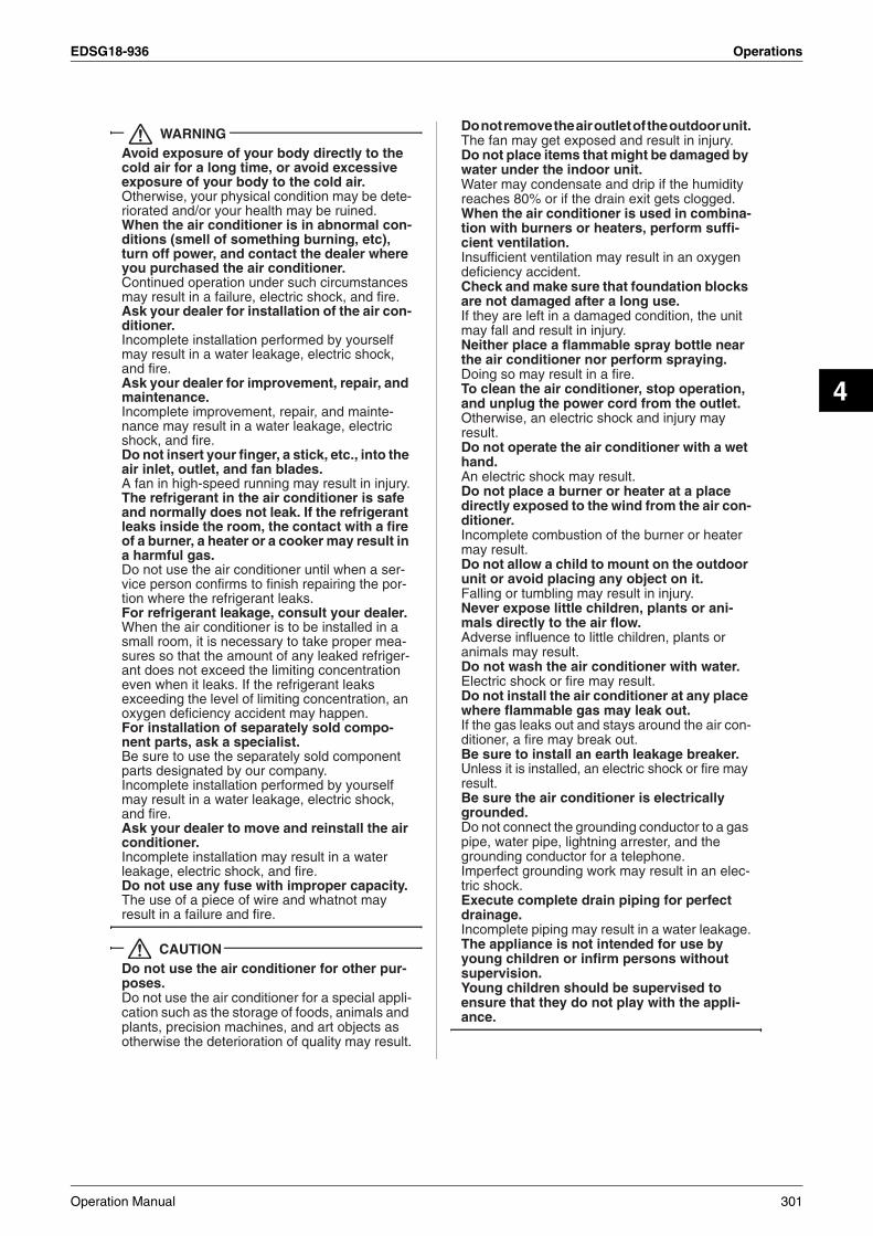
EDSG18-936 Operations
4
WARNINGAvoid exposure of your body directly to the cold air for a long time, or avoid excessive exposure of your body to the cold air.Otherwise, your physical condition may be dete-riorated and/or your health may be ruined.When the air conditioner is in abnormal con-ditions (smell of something burning, etc), turn off power, and contact the dealer where you purchased the air conditioner.Continued operation under such circumstances may result in a failure, electric shock, and fire.Ask your dealer for installation of the air con-ditioner.Incomplete installation performed by yourself may result in a water leakage, electric shock, and fire.Ask your dealer for improvement, repair, and maintenance.Incomplete improvement, repair, and mainte-nance may result in a water leakage, electric shock, and fire.Do not insert your finger, a stick, etc., into the air inlet, outlet, and fan blades.A fan in high-speed running may result in injury.The refrigerant in the air conditioner is safe and normally does not leak. If the refrigerant leaks inside the room, the contact with a fire of a burner, a heater or a cooker may result in a harmful gas.Do not use the air conditioner until when a ser-vice person confirms to finish repairing the por-tion where the refrigerant leaks.For refrigerant leakage, consult your dealer.When the air conditioner is to be installed in a small room, it is necessary to take proper mea-sures so that the amount of any leaked refriger-ant does not exceed the limiting concentration even when it leaks. If the refrigerant leaks exceeding the level of limiting concentration, an oxygen deficiency accident may happen.For installation of separately sold compo-nent parts, ask a specialist.Be sure to use the separately sold component parts designated by our company.Incomplete installation performed by yourself may result in a water leakage, electric shock, and fire.Ask your dealer to move and reinstall the air conditioner.Incomplete installation may result in a water leakage, electric shock, and fire.Do not use any fuse with improper capacity.The use of a piece of wire and whatnot may result in a failure and fire.
CAUTIONDo not use the air conditioner for other pur-poses.Do not use the air conditioner for a special appli-cation such as the storage of foods, animals and plants, precision machines, and art objects as otherwise the deterioration of quality may result.
Do not remove the air outlet of the outdoor unit.The fan may get exposed and result in injury.Do not place items that might be damaged by water under the indoor unit.Water may condensate and drip if the humidity reaches 80% or if the drain exit gets clogged.When the air conditioner is used in combina-tion with burners or heaters, perform suffi-cient ventilation.Insufficient ventilation may result in an oxygen deficiency accident.Check and make sure that foundation blocks are not damaged after a long use.If they are left in a damaged condition, the unit may fall and result in injury.Neither place a flammable spray bottle near the air conditioner nor perform spraying.Doing so may result in a fire.To clean the air conditioner, stop operation, and unplug the power cord from the outlet.Otherwise, an electric shock and injury may result.Do not operate the air conditioner with a wet hand.An electric shock may result.Do not place a burner or heater at a place directly exposed to the wind from the air con-ditioner.Incomplete combustion of the burner or heater may result.Do not allow a child to mount on the outdoor unit or avoid placing any object on it.Falling or tumbling may result in injury.Never expose little children, plants or ani-mals directly to the air flow.Adverse influence to little children, plants or animals may result.Do not wash the air conditioner with water.Electric shock or fire may result.Do not install the air conditioner at any place where flammable gas may leak out.If the gas leaks out and stays around the air con-ditioner, a fire may break out.Be sure to install an earth leakage breaker.Unless it is installed, an electric shock or fire may result.Be sure the air conditioner is electrically grounded.Do not connect the grounding conductor to a gas pipe, water pipe, lightning arrester, and the grounding conductor for a telephone.Imperfect grounding work may result in an elec-tric shock.Execute complete drain piping for perfect drainage.Incomplete piping may result in a water leakage.The appliance is not intended for use by young children or infirm persons without supervision.Young children should be supervised to ensure that they do not play with the appli-ance.
Operation Manual 301

Operations EDSG18-936
If the temperature or the humidity is beyond the fol-lowing conditions, safety devices may work and the air conditioner may not operate, or sometimes, water may drop from the indoor unit.
COOLING ONLY TYPE
HEAT PUMP TYPE
D B: Dry bulb temperatureWB: Wet bulb temperature
The setting temperature range of the remote con-troller is 16°C to 32°C.
Regarding places for installation• Is the air conditioner installed at a well-ventilated
place where there are no obstacles around?• Do not use the air conditioner in the following
places.a. Filled with much mineral oil such as cutting oilb. Where there is much salt such as a beach areac. Where sulfured gas exists such as a hot-spring
resortd. Where there are considerable voltage fluctua-
tions such as a factory or plante. Vehicles and vessels f . Where there is much spray of oil and vapor
such as a cookery, etc.g. Where there are machines generating electro-
magnetic wavesh. Filled with acid and/or alkaline steam or vapor
• Is a snow protection measure taken?For details, consult your dealer.
3. OPERATION RANGE
TEMPERATURE[°C]
OUTDOOR INDOOR
–5 to 46(DB) 21 to 32(DB)/14 to 23(WB)
OPERATIONTEMPERATURE[°C]
OUTDOOR INDOOR
COOLING –5 to 46(DB) 21 to 32(DB)/14 to 23(WB)
HEATING –14 to 21(DB)/–15 to 15.5(WB) 14 to 28(DB)
4. INSTALLATION SITE
Regarding wiring• All wiring must be performed by an authorized
electrician.To do wiring, ask your dealer. Never do it by yourself.
• Make sure that a separate power supply cir-cuit is provided for this air conditioner and that all electrical work is carried out by quali-fied personnel according to local laws and regulations.
Pay attention to running noises, too• Are the following places selected?
a. A place that can sufficiently withstand the weight of the air conditioner with less running noises and vibrations.
b. A place where the hot wind discharged from the air outlet of the outdoor unit and the running noises.
• Are you sure that there are no obstacles near the air outlet of the outdoor unit?Such obstacles may result in declined perfor-mance and increased running noises.
• If abnormal noises occur in use, consult your dealer.
Regarding drainage of drain piping• Is the drain piping executed to perform com-
plete drainage?If proper drainage is not carried out from the out-door drain pipes during air-conditioning operation, chances are that dust and dirt are clogged in the pipe. This may result in a water leakage from the indoor unit. Under such circumstances, stop the operation of the air conditioner, and then consult your dealer or our service station.
302 Operation Manual

EDSG18-936 Operations
4
Refer to figure 1 on page [1] The illustrations in this operating manual corre-spond to the remote control format BRC1C type. Although the display and shape of the buttons on the BRC1B type are slightly different, they may be operated in the same manner.
5. NAME AND FUNCTION OF EACH SWITCH AND DISPLAY ON THE REMOTE CONTROLLER
1ON/OFF BUTTONPress the button and the system will start. Press the button again and the system will stop.
2OPERATION LAMP (RED)The lamp lights up during operation.
3
DISPLAY “ ” (UNDER CENTRAL-IZED CONTROL)When this display shows, the system is UNDER CENTRALIZED CONTROL.
4
DISPLAY “ ” “ ” “ ” “ ” “ ” (OPERATION MODE)This display shows the current OPERATION MODE. For cooling only type, “ ” (Auto) and “ ” (Heating) are not installed.
5
DISPLAY “ TEST” (INSPECTION/TEST OPERATION)When the INSPECTION/TEST OPERATION BUTTON is pressed, the display shows the system mode is in.
6DISPLAY “ ” (PROGRAMMED TIME)
This display shows the PROGRAMMED TIME of the system start or stop.
7DISPLAY “ ” (SET TEMPERATURE)This display shows the set temperature.
8DISPLAY “ ” (FAN SPEED)This display shows the set fan speed.
9DISPLAY “ ” (TIME TO CLEAN AIR FIL-TER)Refer to “HOW TO CLEAN THE AIR FILTER”.
10DISPLAY “ ” (DEFROST)Refer to “DEFROST OPERATION”.
hr
hr
C
Refer to figure 1 on page [1]
• Operating procedure varies with heat pump type and cooling only type. Contact your Daikin dealer to confirm your system type.
• To protect the unit, turn on the main power switch 6 hours before operation.
• If the main power supply is turned off during oper-ation, operation will restart automatically after the power turns back on again.
11
NON-FUNCTIONING DISPLAYIf that particular function is not available, pressing the button may display the words “NOT AVAILABLE” for a few seconds.When running multiple units simultaneouslyThe “NOT AVAILABLE” message will only be appear if none of the indoor units is equipped with the function. If even one unit is equipped with the function, the display will not appear.
12TIMER MODE START/STOP BUTTONRefer to “PROGRAM TIMER OPERATION”.
13TIMER ON/OFF BUTTONRefer to “PROGRAM TIMER OPERATION”.
14INSPECTION/TEST OPERATION BUTTONThis button is used only by qualified service persons for maintenance purposes.
15PROGRAMMING TIME BUTTONUse this button for programming “START and/or STOP” time.
16TEMPERATURE SETTING BUTTONUse this button for SETTING TEMPERA-TURE.
17FILTER SIGN RESET BUTTONRefer to “HOW TO CLEAN THE AIR FILTER”.
18FAN SPEED CONTROL BUTTONPress this button to select the fan speed, HIGH or LOW, of your choice.
19OPERATION MODE SELECTOR BUTTONPress this button to select OPERATION MODE.
NOTE• For the sake of explanation, all indications are
shown on the display in figure 1 contrary to actual running situations.
6. OPERATION PROCEDURE
Operation Manual 303

Operations EDSG18-936
Operate in the following order.
OPERATION MODE SELEC-TOR
Press OPERATION MODE SELECTOR but-ton several times and select the OPERA-TION MODE of your choice as follows.
COOLING OPERATION ......................... “ ”HEATING OPERATION.......................... “ ”AUTOMATIC OPERATION..................... “ ”
• In this operation mode, COOL/HEAT changeover is automatically conducted.
FAN OPERATION................................... “ ”DRY OPERATION .................................. “ ”
• The function of this program is to decrease the humidity in your room with the minimum tem-perature decrease.
• Micro computer automatically determines TEMPERATURE and FAN SPEED.
• This system does not go into operation if the room temperature is below 16°C.
Refer to figure 3 on page [1] • For cooling only type, “COOLING”, “FAN” and
“DRY” operation are able to select.
ON/OFF
Press ON/OFF buttonOPERATION lamp lights up or goes off and the sys-tem starts or stops OPERATION.
[EXPLANATION OF HEATING OPERATION]
DEFROST OPERATION• As the frost on the coil of an outdoor unit increase,
heating effect decreases and the system goes into DEFROST OPERATION.
• The indoor unit fan stops and the remote control-ler display shows “ ”.
• After 6 to 8 minutes (maximum 10 minutes) of DEFROST OPERATION, the system returns to HEATING OPERATION.
Regarding outside air temperature and heat-ing capacity• The heating capacity of the air conditioner
declines as the outside air temperature falls. In such a case, use the air conditioner in combina-tion with other heating systems.
• A warm air circulating system is employed, and therefore it takes some time until the entire room is warmed up after the start of operation.
COOLING, HEATING, AUTOMATIC, FAN, AND PROGRAM DRY OPERATION
1
2
• An indoor fan runs to discharge a gentle wind automatically until the temperature inside the air conditioner reaches a certain level. At this time, the remote controller displays “ ”. Leave it as it stands and wait for a while.
• When the warm air stays under the ceiling and your feet are cold, we recommend that you use a circulator (a fan to circulate the air inside the room). For details, consult your dealer.
For programming TEMPERATURE, FAN SPEED and AIR FLOW DIRECTION, follow the procedure shown below.
TEMPERATURE SETTING
Press TEMPERATURE SETTING button and program the setting temperature.
Each time this button is pressed, setting temperature rises 1°C.
Each time this button is pressed, setting temperature lowers 1°C.
• The setting is impossible for fan operation.
NOTE• The setting temperature range of the remote con-
troller is 16°C to 32°C.
FAN SPEED CONTROL
Press FAN SPEED CONTROL button.High or Low fan speed can be selected.The microchip may sometimes control the fan speed in order to protect the unit.
Operate in the following order.• The timer is operated in the following two ways.• Programming the stop time ( ) ....
The system stops operating after the set time has elapsed.
• Programming the start time ( ) .... The system starts operating after the set time has elapsed.
• The timer can be programmed a maximum of 72 hours.
• The start and the stop time can be simultaneously programmed.
ADJUSTMENT
PROGRAM TIMER OPERATION
304 Operation Manual

EDSG18-936 Operations
4
TIMER MODE START/STOP
Press the TIMER MODE START/STOP button several times and select the mode on the display.The display flashes.For setting the timer stop .... “ ”For setting the timer start .... “ ”
PROGRAMMING TIME
Press the PROGRAMMING TIME button and set the time for stopping or starting the sys-tem.
When this button is pressed, the timeadvances by 1 hour.
When this button is pressed, the timegoes backward by 1 hour.
TIMER ON/OFF
Press the TIMER ON/OFF button.The timer setting procedure ends. The display “ or ” changes from flash-ing light to a constant light.
Refer to figure 4 on page [1]
NOTE• When setting the timer Off and On at the same time,
repeat the above procedure from to once again.
When the timer is programmed to stop the system after 3 hours and start the system after 4 hours, the system will stop after 3 hours and then 1 hour later the system will start.• After the timer is programmed, the display shows
the remaining time.• Press the TIMER ON/OFF button once again to
cancel programming. The display vanishes.
Observe the following precautions to ensure the system operates.• Adjust the room temperature properly for a comfort-
able environment. Avoid excessive heating or cooling.• Prevent direct sunlight from entering a room dur-
ing cooling operation by using curtains or blinds.• Ventilate the room regularly.
Using the unit for long periods of time requires attentive ventilation of the room.
1
2
3
7. OPTIMUM OPERATION
1 3
• Keep doors and windows closed. If the doors and windows remain open, room air will flow out and cause to decrease the effect of cooling and heating.
• Do not place other heaters directly below the indoor unit.They may deform due to the heat.
• Never place objects near the air inlet and the air outlet of the unit. It may cause deterioration in the effect or stop in the operation.
• Turn off the main power supply switch when it is not used for long periods of time. When the main power switch is turned on, some watts of electric-ity is being used even if the system is not operat-ing. Turn off the main power supply switch for saving energy. When reoperating, turn on the main power supply switch 6hours before opera-tion for smooth running (Refer to MAINTE-NANCE).
• When the display shows “ ” (TIME TO CLEAN AIR FILTER), ask a qualified service person to clean the filters (Refer to MAINTENANCE).
ONLY A QUALIFIED SERVICE PERSON IS ALLOWED TO PERFORM MAINTENANCE
IMPORTANT!• BEFORE OBTAINING ACCESS TO TERMINAL
DEVICES, ALL POWER SUPPLY CIRCUITS MUST BE INTERRUPTED
• To clean the air conditioner, be sure to stop oper-ation, and turn the power switch off. Otherwise, an electric shock and injury may result.
• Do not wash the air conditioner with water.Doing so may result in an electric shock.
• Be careful with a scaffold or staging.Caution must be exercised because of work at a high place.
HOW TO CLEAN THE AIR FILTERClean the air filter when the display shows “ ” (TIME TO CLEAN AIR FILTER). It will display that it will operate for a set amount of time.Increase the frequency of cleaning if the unit is installed in a room where the air is extremely contaminated.If the dirt becomes impossible to clean, change the air filter. (For changing air filter, please contact your dealer.)
8. MAINTENANCE(FOR SERVICE PERSONNEL)
Operation Manual 305

Operations EDSG18-936
1. Open the suction grille.Slide both knobs simultaneously as shown and then pull them downward.(Do the same procedure for closing.) (Refer to Fig.1)
(If chains are present. Unhook the chains.) (Refer to Fig.2)
2. Remove the air filters.Remove the air filters by pulling its cloth forward. (Refer to Fig.3)
3. Clean the air filter.Use vacuum cleaner A) or wash the air filter with water B).A)Using a vacuum cleaner
B)Washing with waterWhen the air filter is very dirty, use soft brush and neutral detergent.
Remove water and dry in the shade.
Fig. 1
Fig. 2
Fig. 3
NOTE• Do not wash the air conditioner with hot water of
more than 50°C, as doing so may result in discol-oration and/or deformation.
• Do not expose it to fire, as doing so may result in burning.
4. Fix the air filter.Align the two hangers and push the air filter up.Confirm that four hangers are fixed. (Refer to Fig.4)
5. Close the suction grille.Refer to item No. 1.
6. After turning on the power, press FILTER SIGN RESET button.The display “ ”(TIME TO CLEAN AIR FIL-TER) vanishes.
HOW TO CLEAN AIR OUTLET, SUCTION GRILLE AND OUTSIDE PANELS• Clean with soft cloth.• When it is difficult to remove stains, use water or
neutral detergent.• Clean the suction grille when it is shut.
NOTE• Do not use gasoline, benzene, thinner, polishing
powder, liquid insecticide. It may cause discolor-ing or warping.
• Do not let the indoor unit get wet. It may cause an electric shock or a fire.
• Do not use water or air of 50°C or higher for clean-ing air filters and outside panels.
START UP AFTER A LONG STOPConfirm the following• Check that the air inlet and outlet are not blocked.
Remove any obstacle.• Check if the earth is connected.
Might there be a broken wire somewhere?Contact your dealer if there are any problems.
Fig. 4
306 Operation Manual

EDSG18-936 Operations
4
Clean the air filter and outside panels• After cleaning the air filter, make sure to attach it.
Turn on the main power supply switch• The display on the remote controller will be shown
when the power is turned on.• To protect the unit, turn on the main power switch
at least 6 hours before operation.
WHAT TO DO WHEN STOPPING THE SYS-TEM FOR A LONG PERIODTurn on FAN OPERATION for a half day and dry the unit.• Refer to “FAN OPERATION”.
Cut off the power supply.• When the main power switch is turned on, some
watts of electricity is being used even if the sys-tem is not operating.Turn off the main power supply switch for saving energy.
• The display on the remote controller will vanish when the main power switch is turned off.
Clean the air filter and the exterior.• Be sure to replace the air filter to its original place
after cleaning. Refer to “MAINTENANCE”.
The following symptoms do not indicate air condi-tioner malfunction
I. THE SYSTEM DOES NOT OPERATE• The system does not restart immediately after
the ON/OFF button is pressed.If the OPERATION lamp lights, the system is in normal condition.It does not restart immediately because a safety device operates to prevent overload of the sys-tem. After 3 minutes, the system will turn on again automatically.
• The system does not restart immediately when TEMPERATURE SETTING button is returned to the former position after pushing the button.If the OPERATION lamp lights, the system is in normal condition.It does not restart immediately because a safety device operates to prevent overload of the sys-tem. After 3 minutes, the system will turn on again automatically.
9. NOT MALFUNCTION OF THE AIR CONDITIONER
• The system does not start when the display shows “ ” (UNDER CENTRALIZED CONTROL) and it flashes for few seconds after pressing an operation button.This is because the system is under centralized con-trol. Flashes on the display indicates that the system cannot be controlled by the remote controller.
• The system does not start immediately after the power supply is turned on.Wait one minute until the micro computer is pre-pared for operation.
II. WHITE MIST COMES OUT OF A UNIT• When humidity is high during cooling opera-
tion (In oily or dusty places)If the inside of an indoor unit is extremely contam-inated, the temperature distribution inside a room becomes uneven. It is necessary to clean the inside of the indoor unit. Ask your Daikin dealer for details on cleaning the unit. This operation requires a qualified service person.
• When the system is changed over to HEATING OPERATION after DEFROST OPERATION.Moisture generated by DEFROST becomes steam and exists.
III.NOISE OF AIR CONDITIONERS• A ringing sound after the unit is started.
This sound is generated by the temperature reg-ulator working. It will quiet down after about a minute.
• A continuous flow “Shuh” sound is heard when the systems is in COOLING or DEFROST OPERATION.This is the sound of refrigerant gas flowing through both indoor and outdoor units.
• A “Shuh” sound which is heard at the start or immediately after the stop of operation or which is heard at the start or immediately after the stop of DEFROST OPERATION. This is the noise of refrigerant caused by flow stop and flow change.
• A continuous low “Shah” sound is heard when the system is in COOLING OPERATION or at a stop.The noise is heard when the drain pump is in operation.
• A “Pishi-pishi” squeaking sound is heard when the system is in operation or after the stop of operation.Expansion and contraction of plastic parts caused by temperature change makes this noise.
IV.DUST FROM THE UNITS• Dust may blow out from the unit after starting
operation from long resting time.Dust absorbed by the unit blows out.
Operation Manual 307

Operations EDSG18-936
V. THE UNITS GIVE OFF ODORSThe unit absorbs the smell of rooms, furniture, cigarettes, etc., and then emits them.
VI.THE LIQUID CRYSTAL OF THE REMOTE CON-TROLLER SHOW “ ”
• It happens immediately after the main power supply switch is turned on.This shows that the remote controller is in normal condition. This continues temporary.
I. If one of the following malfunctions occurs, take the measures shown below and contact your Daikin dealer.
The system must be repaired by a qualified service person.
WARNINGWhen the air conditioner is in abnormal con-ditions (smell of something burning, etc), turn off power, and contact your dealerContinued operation under such circumstances may result in a failure, electric shock, and fire.
• If a safety device such as a fuse, a breaker, or an earth leakage breaker frequently actuates, or ON/OFF switch does not properly work.Measure: Turn off the main power switch
• If water leaks from unit.Measure: Stop the operation.
• If the display “ ” (INSPECTION), “UNIT No.”, and the OPERATION lamp flash and the MAL-FUNCTION CODE appears.
Measure: Notify your Daikin dealer and inform him/her of the display.
10. TROUBLE SHOOTING
II. If the system does not properly operate except for the above mentioned case, and none of the above mentioned malfunctions is evident, investigate the system according to the following procedures.
1. If the system does not operate at all.• Check if there is a power failure.
Wait until power is restored. If power failure occurs during operation, the system automati-cally restarts immediately after the power sup-ply recovers.
• Check if the fuse has blown or breaker has worked. Change the fuse or set the breaker.
2. If the system stops operating after operating the system.• Check if the air inlet or outlet of outdoor or
indoor unit is blocked by obstacles.Remove the obstacle and make it well-venti-lated.
• Check if the air filter is clogged.Ask a qualified service person to clean the air filters (Refer to MAINTENANCE).
3. The system operates but it does not suffi-ciently cool or heat.• If the air inlet or outlet of the indoor or the out-
door unit is blocked with obstacles.Remove the obstacle and make it well-venti-lated.
• If the air filter is clogged.Ask a qualified service person to clean the air filters (Refer to MAINTENANCE).
• If the set temperature is not proper (Refer to ADJUSTMENT).
• If the FAN SPEED button is set to LOW SPEED (Refer to ADJUSTMENT).
• If the doors or the windows are open. Shut doors or windows to prevent wind from coming in.
• If direct sunlight enters the room (when cool-ing).Use curtains or blinds.
• When there are too many inhabitants in the room (when cooling).Cooling effect decreases if heat gain of the room is too large.
• If the heat source of the room is excessive (when cooling).Cooling effect decreases if heat gain of the room is too large.
OPERATION lamp
INSPECTION display
MALFUNCTION CODE
INDOOR UNIT No. in which a malfunction occurs
UNIT No.
C L H
3P156215-3
308 Operation Manual

EDSG18-936
Options 309
5
Part 5Options
1. Option List ...........................................................................................3101.1 Outdoor Units .......................................................................................3101.2 BP Units ...............................................................................................3101.3 Indoor Units ..........................................................................................310
2. Options for Outdoor & BP Units ..........................................................3142.1 Options for Outdoor Units.....................................................................3142.2 Options for BP Units.............................................................................315
3. Options for Indoor Units ......................................................................3183.1 Duct Connected Type...........................................................................3183.2 Ceiling Mounted Cassette Type (600×600)..........................................3193.3 Ceiling Mounted Cassette Type (950×950)..........................................3293.4 Ceiling Mounted Built-in Type ..............................................................345
4. Control Devices...................................................................................3554.1 <DCS302CA61> Central Remote Controller .......................................3554.2 <DCS301BA61> Unified ON/OFF Controller .......................................3874.3 <DST301BA61> Schedule Timer .........................................................3954.4 Combination of <DCS302CA61 / DCS301BA61 / DST301BA61>
Combinations of Optional Controllers for Centralized Control..............4144.5 <KRP928B2S> Interface Adaptor for DIII-NET
(Residential Air Conditioner) ................................................................4174.6 <DTA112BA51> Interface Adaptor for DIII-NET (SkyAir).....................4194.7 <KRC72> Centralized Control Board-up to 5 Rooms...........................4214.8 <KRP413A1S> Wiring Adaptor for Timer Clock / Remote Controller...4234.9 <KRP4AA51/53> Wiring Adaptor for Electrical Appendices.................4274.10 <KRP1BA54/57> Adaptor for Wiring ....................................................4324.11 <KRP1BA101> Installation Box for Adaptor PCB ................................4334.12 <KRCS01-1B> Remote Sensor............................................................4354.13 <BRC1C61> Wired Remote Controller for SkyAir................................4384.14 <BRC7C613W> Wireless Remote Controller.......................................4454.15 <BRC7E531W> Wireless Remote Controller.......................................450

Option List EDSG18-936
1. Option List1.1 Outdoor Units
1.2 BP Units
1.3 Indoor Units
Wall Mounted Type
Note: 1 A wiring adaptor (KRP413A1S) is also required for each indoor unit.2 Time clock and other devices ; obtained locally.3 An interface adaptor (KRP928B2S) is also required for each indoor unit.
Note: 1 A wiring adaptor (KRP413A1S) is also required for each indoor unit.2 Time clock and other devices ; obtained locally.3 An interface adaptor (KRP928B2S) is also required for each indoor unit.
Option Name RMKS112/140/160E
1 Cool/Heat Selector KRC19-26A
2 Cool/Heat Selector Fixing Box KJB111A
3 Drain Plug KKPJ5F180
4 Fixture for Preventing Overturning KPT-60B160
5 Wire Type Fixture for Preventing Overturning K-KYZP15C
Option Name BPMKS967B2(3)B
1 REFNET Joint KHRP26A22T
Option Name FTKS25/35D FTKS50/60/71F
1 Centralized Control Board-up to 5 Rooms 1 KRC72
2 Wiring Adaptor for Timer Clock/Remote Controller 2(Normal Open Pulse Contact / Normal Open Contact) KRP413A1S
3 Central Remote Controller 3 DCS302CA61
4 Unified ON/OFF Controller 3 DCS301BA61
5 Schedule Timer 3 DST301BA61
6 Interface Adaptor for DIII-NET (Residential Air Conditioner) KRP928B2S
7 Titanium Apatite Photocatalytic Air Purifying Filter (without Frame) KAF970A46 KAF952B42
8 Remote Controller Loss Prevention with Chain KKF917A4
Option Name FTKS50B
1 Centralized Control Board-up to 5 Rooms 1 KRC72
2 Wiring Adaptor for Timer Clock/Remote Controller 2(Normal Open Pulse Contact / Normal Open Contact) KRP413A1S
3 Central Remote Controller 3 DCS302CA61
4 Unified ON/OFF Controller 3 DCS301BA61
5 Schedule Timer 3 DST301BA61
6 Interface Adaptor for DIII-NET (Residential Air Conditioner) KRP928B2S
7 Air Purifying Filter with Photocatalytic Deodorizing Function (without Frame) KAF952A42
8 Remote Controller Loss Prevention with Chain KKF917A4
310 Options

EDSG18-936 Option List
5
Duct Connected Type
Note: 1 A wiring adaptor (KRP413A1S) is also required for each indoor unit.2 Time clock and other devices ; obtained locally.3 An interface adaptor (KRP928B2S) is also required for each indoor unit.
Ceiling Mounted Cassette Type (600×600)
Note: 1 Wiring for wired remote controller should be obtained locally.2 Installation box for adaptor PCB (KRP1BA101) is necessary.3 An interface adaptor (DTA112BA51) is also required for each indoor unit.
Option Name FDKS25/35CAFDKS50C FDKS60C FDKS25/35EA
1 Centralized Control Board-up to 5 Rooms 2 KRC72
2 Wiring Adaptor for Timer Clock/Remote Controller 3(Normal Open Pulse Contact / Normal Open Contact) KRP413A1S
3 Central Remote Controller 4 DCS302CA61
4 Unified ON/OFF Controller 4 DCS301BA61
5 Schedule Timer 4 DST301BA61
6 Interface Adaptor for DIII-NET (Residential Air Conditioner) KRP928B2S
7 Suction Grille KDGF19A45
8 Insulation Kit for High Humidity KDT25N50 KDT25N63 KDT25N32
9 Remote Controller Loss Prevention with Chain KKF917A4
Option Name FFQ25/35/50/60B
1 Decoration Panel (required) BYFQ60B8W1
2 Remote Controller (required)
Wired Type 1 BRC1C61
Wireless Type Cooling Only BRC7E531W
3 Sealing Member of Air Discharge Outlet KDBHQ44BA60 (KDBHQ44B60)
4 Panel Spacer KDBQ44BA60A (KDBQ44B60A)
5 Fresh Air Intake Kit Direct Installation Type KDDQ44XA60 (KDDQ44X60)
6 Longlife Filter KAFQ441BA60 (KAFQ441B60)
7 Central Remote Controller 3 DCS302CA61
8 Unified ON/OFF Controller 3 DCS301BA61
9 Schedule Timer 3 DST301BA61
10 Interface Adaptor for DIII-NET (SkyAir) DTA112BA51
11 Wiring Adaptor for Electrical Appendices 2 KRP4AA53
12 Adaptor for Wiring 2 KRP1BA57
13 Installation Box for Adaptor PCB KRP1BA101
14 Remote Sensor KRCS01-1B
Options 311

Option List EDSG18-936
Ceiling Mounted Cassette Type (950×950)
Note: 1 With a suction chamber. Fresh air is intaken from 2 holes on the sides of the connection chamber. (This method should be selected if a wireless remote controller is used.)
2 Without a suction chamber. Fresh air is intaken from 2 holes on the connection chamber via a T-shaped pipe connection. (A wireless remote controller can not be used in this case.)
3 Without a suction chamber. Fresh air is intaken directly from a hole on the main unit.4 Installation box for adaptor PCB (KRP1B98) is necessary5 An interface adaptor (DTA112BA51) is also required for each indoor unit.
Option Name FCQ35/50/60/71B
1 Decoration Panel (required) BYC125K-W1
2 Remote Controller(required)
Wired Type BRC1C61
Wireless Type Cooling Only BRC7C613W
3 Panel Spacer KDBP55H160WA
4 Fresh Air Intake KitChamber Type
Without T-shaped Pipe and Fan 1 KDDP55D160
With T-shaped Pipe, without Fan 2 KDDP55D160K
Direct Installation Type 3 KDDJ55X160
5 High Efficiency Filter(Colorimetric Method 65%) KAFP556D80
(Colorimetric Method 90%) KAFP557D80
6 Replacement High Efficiency Filter
(Colorimetric Method 65%) KAFP552H80
(Colorimetric Method 90%) KAFP553H80
7 High Efficiency Filter Chamber KDDF55DA160
8 Replacement Longlife Filter KAF551KA160
9 Branch Duct Chamber KDJ55K80
10 Wiring Adaptor for Electrical Appendices 4 KRP4AA53
11 Adaptor for Wiring 4 KRP1BA57
12 Installation Box for Adaptor PCB KRP1B98
13 Central Remote Controller 5 DCS302CA61
14 Unified ON/OFF Controller 5 DCS301BA61
15 Schedule Timer 5 DST301BA61
16 Interface Adaptor for DIII-NET (SkyAir) DTA112BA51
312 Options

EDSG18-936 Option List
5
Ceiling Mounted Built-in Type
Note: 1 An interface adaptor (DTA112BA51) is also required for each indoor unit.
Option Name FBQ60/71B
1 Decoration Panel (required) BYBS71DAW1 (BYBS71DJW1)
2 Remote Controller(required) Wired Type BRC1C61
3 Service Access Panel KTB25KA80W
4 High Efficiency Filter(Colorimetric Method 65%) KAF252LA80
(Colorimetric Method 90%) KAF253LA80
5 Replacement Longlife Filter Resin net KAFJ251K80
6 Filter Chamber for Rear Suction KAJ25L80B
7 Filter Chamber for Bottom Suction KAJ25L80D
8 Canvas Duct (Air Suction Canvas) KSA-25KA80
9 Discharge Grilleφ150 K-DG5DW
φ200 K-DG9DW
10 Discharge Chamberφ150 K-DGC5D
φ200 K-DGC9D
11 Branch Duct φ200→φ150 K-DDV20A
12 Flexible Duct
φ150 K-FDS151C(1m)/K-FDS152C(2m)/K-FDS153C(3m)/K-FDS154C(4m)/K-FDS155C(5m)/K-FDS156C(6m)
φ200 K-FDS201C(1m)/K-FDS202C(2m)/K-FDS203C(3m)/K-FDS204C(4m)/K-FDS205C(5m)/K-FDS206C(6m)
13 Blind Board KBBJ25KA80
14 Adaptor for Discharge KDAJ25KA71
15 Flange for Suction KDJ2507K80
16 Wiring Adaptor for Electrical Appendices KRP4AA51
17 Adaptor for Wiring (Interlock for Fresh Air Intake Fan) KRP1BA54
18 Central Remote Controller 1 DCS302CA61
19 Unified ON/OFF Controller 1 DCS301BA61
20 Schedule Timer 1 DST301BA61
21 Interface Adaptor for DIII-NET (SkyAir) DTA112BA51
Options 313

Options for Outdoor & BP Units EDSG18-936
2. Options for Outdoor & BP Units 2.1 Options for Outdoor Units2.1.1 <KKPJ5F180> Drain PlugInstallation Manual
Use this plug to connect a drain hose to dispose the drain from the outdoor unit.
3P066795-1B
314 Options

EDSG18-936 Options for Outdoor & BP Units
5
2.2 Options for BP Units2.2.1 <KHRP26A22T> REFNET Joint
Dimensions
Installation Manual
GAS SIDE JOINT
I.Dφ12.7I.Dφ15.9
INSULATION
I.Dφ15.9I.Dφ19.1I.Dφ22.2 O.Dφ15.9 I.Dφ19.1I.Dφ12.7
O.Dφ19.1
80
100 80I.Dφ15.9
I.Dφ12.7
(42)338
380
ACCESSORY
LIQUID SIDE JOINT
REDUCER : GAS SIDE : 2pcsINSULATION : 2pcs
I.Dφ9.5INSULATION
I.Dφ9.5 INSTALLATION MANUALI.Dφ6.4
80I.Dφ9.5
I.Dφ6.4
(40)250
290
D3K05234A
φ25.4
REDUCER (FOR LIQUID PIPE)
KHRP26A72T
φ22.2
S H A P E
φ12.7
REDUCER (FOR GAS PIPE)KIT NAME
φ22.2
2 pcs.
∗…Make sure gas side joint and liquid side joint are for R410A. (Label for R410A is attached on each part.)
KHRP26A22T
LIQUID SIDE JOINT
φ28.6 2 PCS.
2 pcs.
φ19.1φ6.4
GAS SIDE JOINT
φ31.8 φ38.1
2 pcs.
2 pcs.
φ22.2 φ15.9
φ19.1
INSULATION
KHRP26A33T
φ28.6
φ25.4/φ22.2
According to the INSTALLATION MANUAL of outdoor unit.
φ22.2
φ19.1
φ22.2
KHRP26A73T
φ19.1
THIS KIT INCLUDES THE FOLLOWING PARTS.
SELECTION PROCEDURE
∗ ∗
Options 315

Options for Outdoor & BP Units EDSG18-936
KHRP26A72T
GAS SIDE JOINT LIQUID SIDE JOINT
KHRP26A22T
The pipe size of each parts are shown below.
KHRP26A33T
KIT NAME
KHRP26A73T
I.Dφ19.1
I.Dφ9.5
I.Dφ9.5
I.Dφ12.7
I.Dφ31.8I.Dφ15.9
I.Dφ25.4
I.Dφ6.4
I.Dφ15.9
I.Dφ9.5
I.Dφ6.4
I.Dφ12.7
Inlet
I.Dφ19.1
I.Dφ19.1
I.Dφ15.9
Outlet
I.Dφ19.1 I.Dφ12.7
I.Dφ15.9I.Dφ25.4
I.Dφ31.8
I.Dφ12.7I.Dφ31.8
Inlet
I.Dφ9.5
I.Dφ25.4
I.Dφ38.1
INSTALLATION PROCEDURE
I.Dφ19.1
Inlet
Outlet
I.Dφ19.1
Inlet
I.Dφ12.7
I.Dφ9.5
I.Dφ6.4
I.Dφ15.9
I.Dφ25.4
OutletInlet
I.Dφ22.2
I.Dφ15.9
I.Dφ9.5I.Dφ15.9
I.Dφ19.1
I.Dφ6.4
I.Dφ28.6
Inlet
I.Dφ12.7
I.Dφ6.4
I.Dφ9.5
I.Dφ9.5
Outlet
I.Dφ9.5
Outlet
I.Dφ19.1
I.Dφ12.7
I.Dφ12.7
Outlet
Outlet
I.Dφ15.9
I.Dφ12.7
Inlet
Inlet
I.Dφ15.9
I.Dφ12.7
I.Dφ15.9
Outlet
I.Dφ15.9
I.Dφ15.9
I.Dφ28.6I.Dφ12.7
Outlet (1)
Outlet (2)
Connections
1 GAS SIDE JOINTTo next joint orindoor unitφ19.1 or φ15.9
Connections
2 LIQUID SIDE JOINT
(Supplied)
Note) For the size of inlet is φ9.5 orthe size of outlet (1) is φ9.5,the size of outlet (2) is φ9.5.· Cut the pipe with a pipe cutter.
To outdoor unit
φ19.1 or φ15.9
φ9.5 or φ6.4φ15.9 or φ12.7
Note) For the size of outlet (1) is φ22.2 orthe size of outlet (2) is φ19.1.
φ22.2 or φ19.1 To outdoor unit
Inlet
Cut in the center of the part Aand connect a field pipe.
· Make sure to flow nitrogen gas through the pipe when brazing.
According to SELECTION PROCEDURE, cut the pipe with a pipe cutter for use.
Note) For the size of inlet is φ19.1 orthe size of outlet (1) is φ19.1,the size of outlet (2) is φ15.9.· Cut the pipe with a pipe cutter.
φ22.2 or φ19.1
Outlet (2)
· (Ex.) FOR KHRP26A33T
Cut in the center of the part Aand connect a field pipe.
Inlet
φ9.5
Outlet (1)To next joint orindoor unit
Cut in the center of the part B,use Pipe size reducer (supplied)and connect a field pipe.
φ12.7 or φ9.5
Field pipe
Part BJoint
Pipe size reducer
Field pipe
Field pipe
Part A
Field pipe
Field pipe
Cut in the center of the connections. Cut in the center of the connections.
Field pipe
Cut in the center of the connections.
Part A
Field pipe
Field pipe
Connections
Joint Joint
316 Options

EDSG18-936 Options for Outdoor & BP Units
5
(Field supply)
· Do not apply extra force on the piping part. The brazed part may be damaged andit may result in gas leakage.
· Install the Joint so that it is branched vertically or horizontally.
Vertical
Insulation of Joint
Horizontal(Inclination 30° Max.)
A
Be sure to insulate the gas and liquid side Joint.
Note) The insulation of the refrigerant piping must be reinforced based on the environment of installation.Otherwise, dew may condensate on the surface of the insulation. For details, see Engineering Data.
(Supplied)
· Insulate by the same method as gas side joint.
· Set the insulation matching the joint and wind the field supplied tape from the centerwithout any clearances on the matching face of insulation.
· Seal the insulation and field piping insulation joint with the field supplied tape.
Joint
"A" ARROW VIEW
LIQUID SIDE
GAS SIDE
INSTALLATION PRECAUTIONS
insulationField piping
±30°
Insulation
Tape
±30°Max.
2P182411-1
Options 317
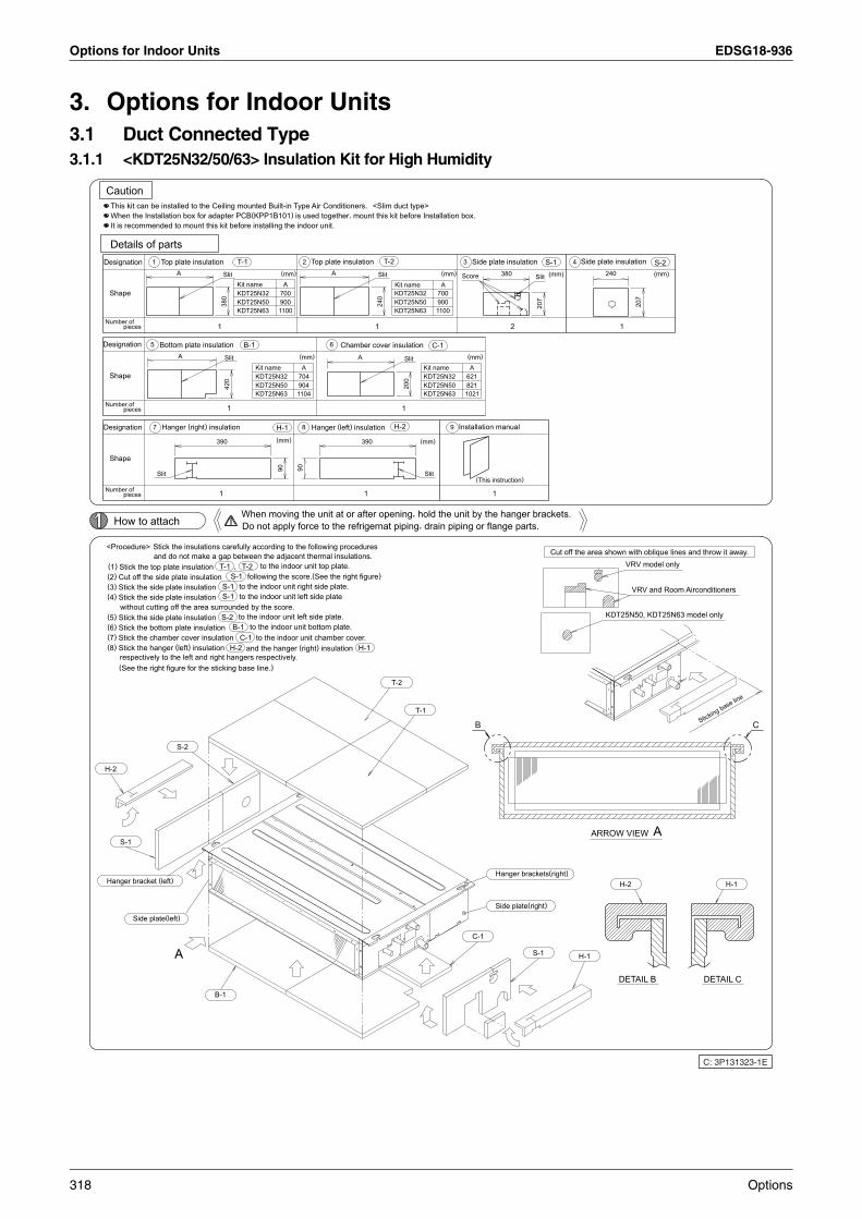
Options for Indoor Units EDSG18-936
3. Options for Indoor Units3.1 Duct Connected Type3.1.1 <KDT25N32/50/63> Insulation Kit for High Humidity
Hanger bracket (left)
Designation
Designation
H-2
Designation
Number of
Number of
Number of
Caution
<Procedure>
(5) Stick the side plate insulation
(4) Stick the side plate insulation(3) Stick the side plate insulation
(8) Stick the hanger (left) insulation(7) Stick the chamber cover insulation(6) Stick the bottom plate insulation
(2) Cut off the side plate insulation(1) Stick the top plate insulation
Shape
Shape
Shape
Details of parts
When the Installation box for adapter PCB(KPP1B101) is used together, mount this kit before Installation box.It is recommended to mount this kit before installing the indoor unit.
This kit can be installed to the Ceiling mounted Built-in Type Air Conditioners. <Slim duct type>
How to attach
S-1
(See the right figure for the sticking base line.)respectively to the left and right hangers respectively.
without cutting off the area surrounded by the score.
pieces
pieces
pieces
Side plate(left)
5
1
7
Slit
Bottom plate insulation
Top plate insulation
Hanger (right) insulation
Stick the insulations carefully according to the following proceduresand do not make a gap between the adjacent thermal insulations.
A
S-2
A
A
B-1
390
1
1
Slit
Slit
1
380
T-1
S-2
S-1S-1
420
KDT25N50
T-1
H-2
KDT25N32
S-1
B-1
When moving the unit at or after opening, hold the unit by the hanger brackets.
,
Do not apply force to the refrigernat piping, drain piping or flange parts.
Kit name
B-1
to the indoor unit left side plate.
to the indoor unit right side plate.to the indoor unit left side plate
C-1
T-2
and the hanger (right) insulation
following the score.(See the right figure)
to the indoor unit bottom plate.to the indoor unit chamber cover.
to the indoor unit top plate.
(mm)
H-1
900KDT25N63 1100
700KDT25N50KDT25N32
900KDT25N63 1100
700
(mm)
A
KDT25N50KDT25N32Kit name
904KDT25N63 1104
704
(mm)
A
KDT25N50KDT25N32Kit name
821KDT25N63 1021
621
(mm)
A
8
2 Top plate insulation
Hanger (left) insulation
6
A
Chamber cover insulationA
390
1
1
Slit
240
T-2
T-2
H-2
Kit name
1
Slit
200
T-1
(mm)
Slit
C-1
(mm)
A
9 Installation manual
3
C-1
Side plate insulation
H-1
(This instruction)
Hanger brackets(right)
Side plate(right)
1
2
S-1
Cut off the area shown with oblique lines and throw it away.
S-1 4
H-1
Side plate insulation
ARROW VIEW A
1
H-2
VRV model only
VRV and Room Airconditioners
S-2
DETAIL B DETAIL C
Sticking base line
H-1
C: 3P131323-1E
(mm)
207
380 SlitScore (mm)
207
24090 90
KDT25N50, KDT25N63 model only
B C
318 Options

EDSG18-936 Options for Indoor Units
5
3.2 Ceiling Mounted Cassette Type (600×600)3.2.1 <BYFQ60B8W1> Decoration Panel
1. BEFORE INSTALLATION
1. PRECAUTIONS• Refer also to the installation manual attached to the indoor unit.
2. ACCESSORIES Installation manual. Screw (4 pcs.)
3. NOTE TO INSTALLER Be sure to instruct the customer how to properly operate the system showing him/her the attached operation
to the indoor unit or the outdoor unit.
2. PREPARATION OF DECORATION PANEL For this unit, you are able to select air flow directions. To discharge air in 2 or 3 directions, it is necessary to
“Sealing member of air discharge outlet”.
HANDLING OF DECORATION PANELS• Never place the panel facing down nor lean it against a wall nor leave it on a projecting object.• Never touch or put pressure on the swing flap.
(The swing flap may malfunction)
(1) Remove the suction grille from the decoration panel.
1 Open the suction grille by sliding the 2 suction grille tabs in the direction of the arrow. (Refer to Fig. 1)
2 Detach the suction grille from the decoration panel by lifting the grille up approximately 45 degrees. (Refer to Fig. 2)
Fig. 1
Fig. 2
45˚
3PA64319-12N-1
manual
purchase optional kit
Options 319

Options for Indoor Units EDSG18-936
3. INSTALLATION OF THE DECORATION PANEL TO THE INDOOR UNIT BODYRefer to the installation manual attached to the indoor unit for the installation of the indoor unit.
(1) Match the “PIPING SIDE” and “DRAIN SIDE” displays on the decoration panel with the position of the piping sectionsection on the indoor unit.
(2) Install the decoration panel.
1 Make sure the wire has not come out of the groove for the wiring route inside the indoor unit. (3 locations)If it has, put it back in.(Connecting the panel with wires out of the groove may cause water leakage.)
2 Temporarily tighten the attached screws approximately 5mm into the opposing sides of the control box in (Refer to Fig. 3)
3 Slide the panel in the direction of the arrow, passing the 2 attachment holes (the “ ” shapes parts) over the ened screws. (Refer to Fig. 4)
4 Hang the panel temporary suspension on the hook located on the control box of indoor unit. (Refer to Fig. 5)
5 Attach the remaining 2 screws, and tighten all 4 screws until the sealant between the decoration panel and indoorcompressed to between 6 and 8 mm thick. (Refer to Fig. 6)
Attached screws Wiring route grooves
(3 locations)(2 locations)
Control box
Fig. 3
Panel temporary suspensionFig. 4
Hook
Control box
Fig. 5
6 - 8 mm
Decoration panel Section of air outlet Fig. 6
Indoor unit
Horizontal blade
Sealant
Ceiling material
and drain
the indoor unit.
temporarily tight
unit is
3PA64319-12N-2
320 Options

EDSG18-936 Options for Indoor Units
5
[ PRECAUTIONS ] Improper screwing of the screws may cause the troubles
shown in Fig. 7, Screw them properly.
If gap is still left between the ceiling and the decoration panel after screwing the screws, readjust the indoor unit body height.
(3) Wiring of the decoration panel (Refer to Fig. 8)
6 Remove the control box lid after making sure the power to the unit is off.
7 Connect the connectors for swing flap motor lead wire installed on the decoration panel.
8 Replace the control box lid reversing the procedure to remove it.
4. INSTALLATION OF SUCTION GRILLE Install the suction grille
Install by reversing the procedure shown in “PREPARATION OF DECORATION PANEL”.It is possible to install the suction grille in 4 directions by turning the suction grille.Change the direction when adjusting the direction of the suction grille of multiple units or in meeting
NOTEBe careful not to get swing flap motor lead wire get caught when installing the suction grille.
Failing to connect the connectors will prevent the swing flap from working, so be sure to connect them.
Make sure that the swing flap motor lead wire is not caught between the indoor unit and the decoration panel.
Fig. 7
Air leak
Air leak from ceiling
Contamination Dew formation, dew dripping
Screws
(2 locations)
Clamping material
Swing motor lead wire
Decoration panel side
Swing motor lead wire
Indoor unit side
Control box lid
Hang the swing motor lead wire on this tab.
Pass the swing motor lead wire through the clamp material as shown in the diagram. After connection, store the connector inside the control box.
Fig. 8
g customers’ demands.
3PA64319-12N-3
Options 321

Options for Indoor Units EDSG18-936
3.2.2 <KDBH44BA60 (KDBHQ44B60)> Sealing Member of Air Discharge Outlet
1P109292B
Contents of kit
Caution
Check the following parts are include with your kit.
Refer to the installation manual for both indoor unit and the decoration panel.
Quantity
Quantity
The direction of air discharge and the positioning of sealing material
Shape
Shape
Name
Name
(1) Selection of the air outlet
(2) Prepare the sealing material
(3) Adhere the sealing material
outletAir
Example) For closing the air outlet
outletAir
Caution
StepPeel off therelease paper.
*When closing the air outlet
Refer toRefer to the installation manual attached to the indoor unit for selection of installation location.
Select the direction of air discharge from the following table according to the location of the indoor unit.
Cut off the sealing materialAdhere the sealing material(Make sure that the sealing material
<How to prepare the sealing material
prepared according to the procedure (2) to the indoor unit air outlet.
Released paper
Sealing material
1
for swing flap
6
Moisture absorber
2
2
2 pieces
3 pieces
Never select the direction of air discharge other than the following pattern.(You may have a condensation problem.)
Setting for indoor unit
Step
of tape for fixing the sealing materialAdhere the sealing material
2
Tape for fixing thesealing material
3
for panel edge
7
Moisture absorber
2 pieces
tape for fixing the sealing materialThe sealing material
3 pieces
8mm×450mm
1
outletAir
outletAir
2
11
to tape for fixing the sealing material
,it is not required to cut off the sealing material1
and the tape for fixing the sealing materialand the tape for fixing the sealing material
3
4
3
and tape for fixing the sealing material
1
1
for setting position number.
2-way air
3-way airdischarge
discharge
3
and tape for fixing the sealing material
is placed at the center of the tape for fixing the sealing material
3
100mm×179mm
for attached point
1 piece
Moisture absorber
4
8
1
-1
Sealing material
1 piece
1
1
to the center
and
Closed
Insulation for side plate
Closed
2
2
2
3
100mm×370mm
1 piece
.
-2
3
1
1
3
3
1
2
9
for flesh air intakeMoisture absorber
Tape for fixing thesealing material
Closed
4
4
outletAir
50mm×20mm
2 pieces
Cut off these pieces.
Step
100mm×1538mm
3
2
Adhering the sealing material for air outlet
1 piece
Closed
-3
3
1
.
2
22
2
2
along the perforated lines (marked---).according to the air outlet No. to be closed.
2
1
1
3
for bell-mouth
4
Moisture absorber
and tape for fixing the sealing material
1 piece
4 2
Sealing material
Sticking reference
for swing flap
5
Moisture absorber
1
Tape for fixing the
3
sealing material
2
25mm×361mm
3 pieces
.)
Indoor unit
Closed
4
1
Closed
2
2
2
(10mm)
1
3
.
( 10m
m)
4
1
>
322 Options
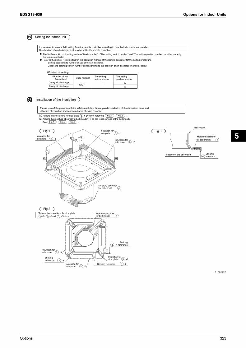
EDSG18-936 Options for Indoor Units
5
1P109292B
Installation of the insulation
Setting for indoor unit
side plateInsulation for
*Adhere the insulations for side plate
The direction of air discharge must also be set by the remote controller.It is required to make a field setting from the remote controller according to how the indoor units are installed.
(2) Adhere the moisture absorber forbell-mouth(1) Adhere the insulations for side plate
3
Please turn off the power supply for safety absolutely, before you do installation of the decoration panel andaffixation of insulation and connected work of swing conector.
side plateInsulation for
-1,
the remote controller.The 3 different kinds of setting such as "Mode number" , "The setting switch number" and "The setting position number" must be made by
Refer to the item of "Field setting" in the operation manual of the remote controller for the setting procedure.
Fig.1
Fig.2
referenceSticking
See
(Content of setting)
3
Check the setting position number corresponding to the direction of air discharge in a table, below.Setting according to number of use of the air discharge.
2-way air discharge3-way air discharge
-2and
3
(Number of useof air outlets)
Fig.1
-3
3
3
3
-3
-3inturn.
-3
Fig.2
side plateInsulation for
Fig.3
Mode number
13(23)
3
.
-2
The settingswitch number
for bell-mouthMoisture absorber
3
Sticking reference
for bell-mouthMoisture absorber
in position, referring
side plateInsulation for
1
4 on the inner surface of the bell-mouth.
side plateInsulation for
3
3
side plate
-1 reference
Insulation for
4
The settingposition number
4
-1
Sticking
3
3
02
03
-2
-1
3
Fig.1
-2
Fig.2 .
Fig.3
Section of the bell-mouth
Bell-mouth
for bell-mouthMoisture absorber
4 referenceSticking
4
Options 323
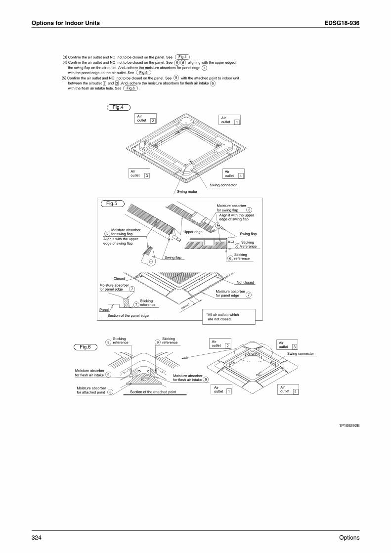
Options for Indoor Units EDSG18-936
1P109292B
(3) Confirm the air outlet and NO. not to be closed on the panel. See(4) Confirm the air outlet and NO. not to be closed on the panel. See
(5) Confirm the air outlet and NO. not to be closed on the panel. See
the swing flap on the air outlet. And, adhere the moisture absorbers for panel edge
between the airoutlet
with the panel edge on the air outlet. See
with the flesh air intake hole. See
for flesh air intakeMoisture absorber
for attached pointMoisture absorber
2
Fig.6
and 3 .And, adhere the moisture absorbers for flesh air intakeFig.6
9
9
8
referenceSticking
.
Fig.5
5
Section of the attached point
6
8.
aligning with the upper edgeof
with the attached point to indoor unit
9 referenceSticking
Fig.4
for flesh air intakeMoisture absorber
Fig.4
.
outletAir
outletAir
7
outletAir
3
outletAir
9
9
2
2
1
Swing motor
Swing connector
outletAir
outletAir
Swing connector
outletAir
outletAir
3
4
1
4
Panel
for panel edgeMoisture absorber
edge of swing flapAlign it with the upper
Section of the panel edge
Fig.5
5 for swing flapMoisture absorber
Closed
7
7 referenceSticking
Swing flap
(30mm)
Upper edge
*All air outlets whichare not closed.
for panel edge
for swing flap
Moisture absorber
Moisture absorber
edge of swing flapAlign it with the upper
6 reference
Not closed
Sticking
6
Swing flap
referenceSticking
7
6
324 Options
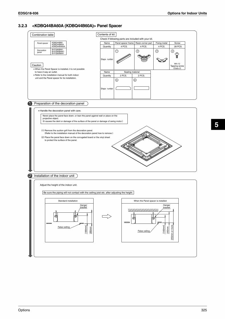
EDSG18-936 Options for Indoor Units
5
3.2.3 <KDBQ44BA60A (KDBQ44B60A)> Panel Spacer
Caution
Combination table
Preparation of the decoration panel
• Refer to the installation manual for both indoor
Installation of the indoor unit
• When the Panel Spacer is installed, it is not possibleto have 2-way air outlet.
unit and the Panel spacer for its installation.
Panel spacer
panelDecoration
• Handle the decoration panel with care.
Adjust the height of the indoor unit.
(1) Remove the suction grill from the decoration panel.
(2) Place the panel face down on the corrugated board or the vinyl sheet
Never place the panel face down, or lean the panel against wall or place on the
(It causes the dent or damage of the surface of the panel or damage of swing motor.)projective object.
Be sure the piping will not contact with the ceiling joist etc. after adjusting the height.
(Refer to the installation manual of the decoration panel how to remove.)
to protect the surface of the panel.
KDBQ44B60KDBQ44B60AKDBQ44BA60A
BYFQ60BW1BYFQ60BAW1BYFQ60B8W1
False ceiling
Standard installation
Hangerbracket
( 180
mm
)
285m
m
Contents of kit
Check if following parts are included with your kit.
Shape · number
Quantity
Quantity
Name
Name Panel spacer frame
5
1
4 PCS.
2 PCS.
Sealing material
When the Panel spacer is installed
Resin corner part
6
False ceiling
2
4 PCS.
2 PCS.
Fixing metal
3
4 PCS.
Tapping screw
4
M4×12
Hangerbracket
(Class 2)
28 PCS.
Screw
( 140
mm
)
245m
m
255m
m o
r m
ore
Shape · number
Options 325

Options for Indoor Units EDSG18-936
Assembly of panel spacer
Adhesion of the sealing material
Installation of the decoration panel
Fixing to the decoration panel
(1) Set the fixing metal on each corner
(1) Assemble the panel spacer frame and the plastic corner joint temporarily.
Adhere the sealing material on the upper face of the panel spacer in the order of and .
Install the decoration panel to the indoor unit according to the installation manual of decoration panel.
the decoration panel extremely.The panel spacer is not firmly fixed to the decoration panel, so that never hold the panel spacer directly or lean
with screws .
5
4
2
6
3
1
5
1
3
6
Decoration panel
4
2
1
(2) Place the panel spacer assembled in itemof the above on the outer frame of the decoration panel.
2
5
1
1
6
1
Insert
Insert
1
2
2
2
3
Panel spacer
the inner rib.)(Adhere it along
Sticking reference
Assembly of panel spacer
(2) Fix with the screws from the top. (4 screws in each corner)
5 6
4
(3) Fix the panel spacer to the fixing metal
Sealing material
4
3
5
with screws
6
Decoration panel
4 (4 portions).
4
4
1P107764-1C
326 Options

EDSG18-936 Options for Indoor Units
5
3.2.4 <KDDQ44XA60 (KDDQ44X60)> Fresh Air Intake Kit
Contents
Necessary tools
2. When installing this kit, duct (Nominal dia. : φ100) is required on site.
Remarks :
Prior to installation, make sure you have the complete kit of parts.
Shape
1. This kit can be installed to the Ceiling mounted cassette type (Multi-flow).
Philips head screw driver, nipper, cutter etc.
Name
Q'ty
Installation procedures of duct flange
· In case that metal duct is penetrated through wooden walls, make sure the duct and the
· Install the duct inclined downwardly to outdoor so that the rain may not get into the duct.
· To avoid birds, small animals or insects getting inside the duct, make sure to install net
1. Cut off the knockout hole on the side plate. (Fig.1)
where it contacts the outside air.
wall electrically insulated.
(Inclination 1/100 to 1/50)
1 Duct flange
1 piece
Side plate
4 pieces
2
M4×12
Screws
Knockout hole
The knockout hole is opposite to ref. pipe.
3 Insulation for duct flange
1 piece
Cut it off
Side plate
with nipper.
Slit
Ref. pipe
4 Insulation for opening of
Drain pipe
Fig.1
1 piece
unit5 Installation manual
1 piece
Options 327

Options for Indoor Units EDSG18-936
Installation procedures of duct <Nominal diameter of duct : φ100>
Precaution· All ducts must be completely insulated.· Do not do the followings when installing duct.
2. Adhere the insulation for opening of unit to the opening. (Fig. 2)
3. Install the duct flange with screws (M4×12, 4 screws) to the opening and adhere the insulation (Fig. 3)
2. After connection, wrap vinyl tape (field supply) around the duct connection to prevent1. Connect the duct to the duct flange. (Flange fits inside the duct.) (Fig. 4)
and hole of the indoor unit.However, put the insulation so as not to conceal the screw hole of the indoor unit.
air leak.
Put the insulation to be suitable for the hole of the insulation
Fig. 4
Insulation
Duct flange
Insulation
A) To bend the duct excessively
Indoor unit
1
3
1
WRONG
Duct flange
Wrap the tape around the duct to avoid air leak.
2
(M4×12, 4screws)Screws
1
2
Fig. 3
Tape
Fig. 2
B) To bend the duct too many times
φ100 Duct (Field supply)
WRONG
C) To reduce the duct diameter
WRONG
3
2P108307-1A
4
4
4
4
4
328 Options

EDSG18-936 Options for Indoor Units
5
3.3 Ceiling Mounted Cassette Type (950×950)3.3.1 <BYC125K-W1> Decoration Panel
Options 329

Options for Indoor Units EDSG18-936
330 Options

EDSG18-936 Options for Indoor Units
5
Options 331

Options for Indoor Units EDSG18-936
332 Options

EDSG18-936 Options for Indoor Units
5
Options 333

Options for Indoor Units EDSG18-936
3.3.2 <KDBP55H160WA> Panel Spacer
Caution
Combination table
Preparation of the Decoration panel
When the Panel Spacer is installed, it is not possible
Refer to the installation manual for both indoor
Installation of the indoor unit
to have 2-way air outlet.
unit and the Panel spacer for its installation.
Panel spacer
panelDecoration
Handle the decoration panel with care.
Adjust the height of the indoor unit.
(1)Remove the suction grill from the decoration panel.
(2)Place the panel face down on the corrugated board or the vinyl sheet
Never place the panel face down, or lean the panel against wall or place on the
(It causes the dent or damage of the surface of the panel or damage of swing motor.)projective object.
Be sure the piping will not contact with the ceiling joist etc. after adjusting the height.
(Refer to the installtion manual of the decoration panel how to remove.)
to protect the surface of the panel.
BYC125KJW1
KDBP55H160WAKDBP55H160FA
BYCP125K-W1 BYC125K-W1BYCP125D-W1
KDB55K160WA
Contents of kitCheck if following parts are included with your kit.
Suspensionbracket
A
Suspensionbracket
A
BYCP125D-W1
BYCP125K-W1
A[mm]
BYC125KJW1145~150
A[mm]
BYC125K-W1
125~130
Standard installation
Ceiling surface
Decoration panel
When the Panel spacer is installed
Ceiling surface
Decoration panel
BYCP125D-W1
BYCP125K-W1
BYC125KJW1105~110BYC125K-W1
85~90
Shape • number
Shape • number
Quantity
Quantity
Name
Name Panel spacer frame
5
1
4 PCS.
2 PCS.Sealing material
Resin corner part
6
2
4 PCS.
2 PCS.
Fixing metal
3
7
4 PCS.
Caution label1 PC.
Tapping screw
4
M4×10(Class 2)
28 PCS.Screw
Others
ThisInstallationManual
334 Options

EDSG18-936 Options for Indoor Units
5
Assembly of panel spacer
Adhesion of the sealing material
Installation of the Decoration panel
Fixing to the Decoration panel
(1)Assemble the panel spacer frame
Adhere the sealing material
(2)After installation of the Decoration panel, adhere the caution sticker
(1) install the decoration panel to the indoor unit according tothe installation manual of decoration panel.
7
The panel spacer is not firmly fixed to the decoration panel, sothat never hold the panel spacer directly or lean the decorationpanel extremely.
next to the name plate of the indoor unit as shown on the right.
5
2
6
1
5
1
6 on the upper face of the panel spacer in the order of
1
2
and the plastic corner joint
(2)Place the panel spacer assembled in itemof the above on the outer frame of the Decoration panel.
2
5
1
1
2
6
1
Insert
temporarily.
Insert
1
2
2
the inner rib.)(Adhere it alongSticking reference
5
upper
3
Name plate forindoor unit
and
Assembly of panel spacer
6
7
.
(2)Fix with the screws
4
Sealing material5
(3)Fix the panel spacer to the fixing metal
6
4
3 with screws 4 (4 portions).
4
4
from the top.(4 screws in each corner)
1P136564E
4
3
4
3
34
(1)Set the fixing metal on each cornerwith screws .
In the cases of other than the above.
(Screw positions change withdecoration panels,as shown in the following figure.)
In the case of BYCP125K-W1
Options 335

Options for Indoor Units EDSG18-936
3.3.3 <KDDP55D160(K)> Fresh Air Intake Kit (Chamber Type)
C h a m b e r
1 P C .1 P C .
H o o k
R e m o v e t h e d e c o r a t i o n p a n e l i n t h e r e v e r s e s t e p w h e n t h e p a n e l i s i n s t a l l e d .
T i g h t e n 2 h e x a h e a d s c r e w s l o c a t e d b e n e a t h t h e l u t c h e s u n t i l t h e t h i c k n e s s o f t h e s e a l i n g m a t e r i a l o f c h a m b e r r e d u c e s t o 5 ~ 8 m m .
I n d o o r u n i t
Installation set outline of the indoor unit∗( W h e n t h e i n d o o r u n i t i s a l r e a d y i n s t a l l e d , h a n g t h e h o o k t o t h e s u s p e n s i o n b r a c k e t t e m p o r a r i l y a n d f i x t h e h o o k . )
I n d o o r u n i t2 5 ~ 8 0
R e m o v e t h e d e c o r a t i o n p a n e l . ( T h i s i s n o t r e q u i r e d f o r t h e n e w i n s t a l l a t i o n )
T e m p o r a r i l y h a n g t h e r e m a i n i n g 2 h o o k s o f t h e s u c t i o n c h a m b e r t o t h e h o o k s o n t h e s i d e s o f t h e i n d o o r u n i t .T e m p o r a r i l y i n s t a l l t h e s u c t i o n c h a m b e r t o t h e i n d o o r u n i t b y h a n g i n g t h e l a t c h o n t h e o p p o s i t e s i d e o f t h e s u c t i o n c h a m b e r t o t h e h o o k o f t h e i n d o o r b o d y . ( 2 p o r t i o n s )
(Refer to the installation manual of the decoration panel for the details.)
3 4 81 0 0 ~ 1 4 03 0 6
I n s p e c t i o n h a t c h
I n d o o r u n i t
b r a c k e tS u s p e n s i o n
S u c t i o n c h a m b e r
I n s p e c t i o n h a t c h
L e a d w i r e
C o n n e c t i n g c h a m b e r ( R i g h t )
W h e n c o m p l e t e dI n d o o r u n i t
D u c t ( F i e l d s u p p l y )
H o o k( 2 p o r t i o n s )f i g . 1
H o o k
S u s p e n s i o n b r a c k e t
A f t e r i n s t a l l a t i o nS u c t i o n c h a m b e r
f i g . 2
f i g . 5
I n s p e c t i o n h a t c h
S u c t i o n c h a m b e r
f i g . 2
f i g . 3
S u s p e n s i o n b r a c k e t
( 2 p o r t i o n s )
W h e n i n s t a l l i n g
I n s p e c t i o n h a t c h
7 2 5
( 4 p o r t i o n s ) p i p eR e f r i g e r a n t
W h e n i n s t a l l i n gf i g . 2
I n d o o r u n i t
f i g . 5f i g . 4
f i g . 4
H o o k
N a m e
S h a p e
C l o s e t h e o p e n i n g w i t h c l o s i n g m a t e r i a l
I n s t a l l a t i o n o f t h e S u c t i o n c h a m b e r
t yQ '
1 . R e f e r t o t h e f o l l o w i n g t a b l e .
C o m p o n e n t s
R E M A R K S
L a t c h
C a u t i o n
M a t e r i a l
K D D P 5 5 D 1 6 0 K
[ E x a m p l e o f o n e s i d e i n t a k e ]
( L e f t )C h a m b e r M a n u a l
m u s t b e l e d f r o m r i g h t s i d e a s s h o w n . I n t h i s c a s e , u s e K D D P 5 5 D 1 6 0 .W h e n i n s t a l l i n g t h e w i r e l e s s r e c e i v e r k i t o n t h e i n d o o r u n i t , t h e d u c t
s a f e t y p r e c a u t i o n s a n d o b s e r v e t h e m t o e n s u r e s a f e t y d u r i n g w o r k .B e f o r e s t a r t i n g t h e i n s t a l l a t i o n w o r k , c a r e f u l l y r e a d t h e f o l l o w i n g
K D D P 5 5 D 1 6 0
( R i g h t )C h a m b e r
I n c a s e o f o n e s i d e i n t a k e , t h e n o i s e w i l l b e l a r g e r t h a n i n t a k e f r o m b o t h s i d e s .
D u c t
M 4 × 1 2
2 . I n s p e c t i o n h a t c h ( l a g e r t h a n 4 5 0 )
I n s t a l l e i t h e r o n e o f h a t c h e s
S e t o u t l i n e o f t h e i n d o o r u n i t
I n t h i s c a s e , m a k e s u r e t o c l o s e t h e o p e n i n g w i t h t h e m a t e r i a lo n e s i d e i n t a k e i s a c c e p t a b l e .W h e n t h e i n t a k e f r o m b o t h s i d e s c a n n o t b e o b t a i n e d d u e t o a n o b s t a c l e ,
I n c a s e o f K D D P 5 5 D 1 6 0
.5
i s s e p a r a t e l y p a c k e d .S h a d e d p a r tC h e c k i f t h e f o l l o w i n g p a r t s a r e i n c l u d e d w i t h y o u r k i t
S e l e c t i o n o f L o c a t i o n a n d A c c e s s D o o r
C o n n e c t i n g3C o n n e c t i n g2 S c r e w4 C l o s i n g5 T J o i n t6 F l e x i b l e7 C l a m p8 I n s t a l l a t i o n9
1PC. 1PC. 4PCS.1PC. 1PC. 4PCS.
1PC.1PC.
1PC.1PC.4PCS.
f i g . 1 f i g . 3
t h e d e c o r a t i o n p a n e l .R e f e r t o t h e i n s t a l l a t i o n m a n u a l s f o r t h e i n d o o r u n i t a n dB e f o r e i n s t a l l a t i o n , m a k e s u r e t h e i n d o o r u n i t n u m b e r . A i r C o n d i t i o n e r < M u l t i - f l o w t y p e > .T h i s k i t c a n b e i n s t a l l e d t o t h e C e i l i n g M o u n t e d C a s s e t t e T y p e ·
··
·1 .
2 .
3 .
O t h e r w i s e , i t m a y c a u s e a i r l e a k o r t h e p r o d u c t m a y f a l l .M a k e s u r e t o u s e t h e a t t a c h e d o r s p e c i f i e d c o m p o n e n t s t o i n s t a l l t h e p r o d u c t s .
A f t e r i n s t a l l a t i o n , c h e c k w h e t h e r t h e r e i s n o a b n o r m a l i t y d u r i n g t h e t r i a l o p e r a t i n g .
S u c t i o n1
2PCS.
∗∗
∗
∗
~
336 Options

EDSG18-936 Options for Indoor Units
5
3K011144-1A
f i g . 5
f i g . 7
f i g . 6
S u c t i o n c h a m b e r
s u s p e n s i o n b r a c k e t
S l i p p i n
(200
)
P a p e r p a t t e r n
F l e x i b l e d u c t
C e i l i n g s u r f a c e
( F i e l d s u p p l i e d )S u s p e n s i o n b a n d f o r d u c t
S u c t i o n c h a m b e r
F i x i n g m e t a l
S c r e w
f i g . 6
C l o s i n g m a t e r i a l
S u c t i o n c h a m b e r
( r i g h t )C o n n e c t i n g c h a m b e r
S u c t i o n c h a m b e r
F r e s h a i r i n t a k e
S c r e w
S c r e w
D e c o r a t i o n p a n e l
R u b b e r b u s h
2
4
1
I n c a s e o f K D D P 5 5 D 1 6 0 K
[ I n s t a l l a t i o n o f c l o s i n g m a t e r i a l i n c a s e o f o n e s i d e i n t a k e ] ( f o r K D D P 5 5 D 1 6 0 )
T o r e d u c e t h e d i a m e t e r
W h e r e i t c o n t a c t t h e o u t s i d e a i r , m a k e s u r e t o i n s t a l l a i r f i l t e r t o p r o t e c t h e a t e x c h a n g e r f o r i n d o o r u n i t .W h e r e i t c o n t a c t t h e o u t s i d e a i r , m a k e s u r e t o i n s t a l l s c r e e n t o a v o i d b i r d s , s m a l l a n i m a l s o r i n s e c t s g e t t i n g i n s i d e t h e d u c t .I n s t a l l t h e o u t d o o r u n i t d u c t i n c l i n e d d o w n w a r d l y s o t h a t t h e r a i n w i l l n o t g e t i n t o t h e d u c t . ( I n c l i n a t i o n 1 / 1 0 0 t o 1 / 5 0 )I n c a s e t h a t m e t a l d u c t i s p e n e t r a t e d t h r o u g h w o o d e n w a l l , m a k e s u r e t h e d u c t a n d t h e w a l l a r e e l e c t r i c a l l y i n s u l a t e d .f o l l o w t h e l o c a l c o d e o r r e g u l a t i o n t o i n s t a l l t h e d u c t .
I n s u l a t e t h e d u c t t o p r e v e n t c o n d e n s a t e .W r a p t h e d u c t t a p e ( F i e l d s u p p l i e d ) a r o u n d t h e c o n n e c t i o n t o p r e v e n t a i r l e a k .
I n s t a l l a t i o n o f C o n n e c t i n g d u c t
T o b e n d t o o m a n y t i m e sT o b e n d e x c e s s i v e l y
< H o w t o t i g h t e n t h e c l a m p >
b y h a n d .T i g h t e n t h e c l a m pt h e s i t o f t h e p i n .o f c l a m p b e t w e e nI n s t a l l t h e e d g e
d u c t t o t h e c h a m b e r .f o r d u c t t o r e d u c e t h e w e i g h t o f H a n g t h e T J o i n t w i t h s u s p e n s i o n b a n d
2 ) D o n o t p e r f o r m t h e f o l l o w i n g d u c t w o r k .
D u c t c o n n e c t i o n
C o r r e c t
2 . C o n n e c t t h e T J o i n t a n d C o n n e c t i n g c h a m b e r .
( i n c l u d e d i n t h e i n d o o r u n i t )
C l o s i n g m a t e r i a l c a n b e u s e d e i t h e r r i g h t o r l e f t s i d e o p e n i n g .I n s t a l l t h e c l o s i n g m a t e r i a l i n a c c o r d a n c e w i t h t h e f o l l o w i n g p r o c e d u r e s .
1 ) A t t a c h t h e d u c t t o t h e o u t s i d e o f t h e B r a n c h d u c t c h a m b e r .
t h e a t t a c h e d s c r e wI n s t a l l t h e c o n n e c t i n g c h a m b e r w i t h< P r o c e d u r e 2 >
F o r t h e h e i g h t o f t h e u n i t , c h a n g e t h e h e i g h t s h o w n o n t h e r i g h t d r a w i n g .
C o m p l e t e d .
( L e v e l o f t h e i n d o o r u n i t )
W r o n g
I n c a s e o f t h e p a n e l f o r W i r e l e s s r e m o t e c o n t r o l l e r
: W i r e f r o m D e c o r a t i o n p a n e l t o s u c t i o n c h a m b e rL e a d w i r e o f D e c o r a t i o n p a n e l
( i n c l u d e d i n t h e i n d o o r u n i t )
( W h e n t h e i n d o o r u n i t i s n e w l y i n s t a l l e d )
I f t u r n e d r e v e r s e l y , r a t c h e t p a r t m a n y b r e a k d o w n .D o n o t t u r n t h e s l i t p i n r e v e r s e l y .
.s u c t i o n c h a m b e rt o s u s p e n s i o n b r a c k e t o fc h a m b e r
H o o k t h e s q u a r e h o l e o f c o n n e c t i n g< P r o c e d u r e 1 >
( F o r t h e h e i g h t o f t h e u n i t , r e f e r t o t h e d r a w i n g o n t h e r i g h t . )
a s s h o w n .( e x . S c r e w d r i v e r o r p l i e r s )c l a m p w i t h s t a n d a r d t o o l sd i r e c t i o n a n d t i g h t e n t h eM a k e s u r e t h e t i g h t e n i n g
C a u t i o n
( B e f o r e f i x i n g t h e C h a m b e r , p u t t h e l e a d w i r e t h r o u g h R u b b e r b u s h i n g h o l e . )
I n s t a l l a t i o n o f D e c o r a t i o n p a n e l
( 4 )( 3 )( 1 ) ( 2 )
i n f i g . 5 .1 . I n s t a l l t h e C o n n e c t i n g c h a m b e r ( r i g h t & l e f t ) i n a c c o r d a n c e w i t h t h e p r o c e d u r e s h o w n
( S a m e a s t h e l e f t s i d e )I n s t a l l a t i o n o f t h e c o n n e c t i n g c h a m b e r ( r i g h t )
I n d o o r u n i t
d u c t .a r o u n d t h eW r a p t h e c l a m p
< D u c t : d i a m e t e r φ 1 5 0 >
I n s t a l l a t i o n o f t h e I n d o o r U n i t a n d t h e S u c t i o n C h a m b e r
. ( 2 p o r t i o n s )4t h e a t t a c h e d s c r e w I n s t a l l t h e c o n n e c t i n g c h a m b e r w i t h< P r o c e d u r e 2 >
( S e e b e l o w )
R e f e r t o t h e i n s t a l l a t i o n m a n u a l o f t h e i n d o o r u n i t .
t h e p a p e r p a t t e r n ][ A t t a c h m e n t o f
C a u t i o nC a u t i o n
R e f e r t o t h e i n s t a l l a t i o n m a n u a l a t t a c h e d t o t h e w i r e l e s s r e m o t e c o n t r o l l e r k i t ( o p t i o n a l ) f o r t h e d e t a i l .P u t t h e C o n n e c t o r f o r r e c e i v e r l e a d w i r e t h r o u g h r u b b e r b u s h a n d c o n n e c t t o t h e i n d o o r P C b o a r d .
f i g . 7
1 .s u c t i o n c h a m b e r
H o o k t h e s q u a r e h o l e o f c o n n e c t i n g< P r o c e d u r e 1 >
t o s u s p e n s i o n b r a c k e t o fc h a m b e r 2
I n s t a l l t h e D e c o r a t i o n p a n e l i n a c c o r d a n c e w i t h t h e i n s t a l l a t i o n m a n u a l a t t a c h e d t o t h e d e c o r a t i o n p a n e l .
I n s t a l l t h e i n d o o r u n i t a n d t h e s u c t i o n c h a m b e r .
A t t a c h t h e p a p e r p a t t e r n f o r i n s t a l l a t i o n t o t h e i n d o o r u n i t w i t h s c r e w s t o p r o t e c t t h e i n d o o r u n i t f r o m d i r t . [ S e e b e l o w ]
I n c a s e o f a t t a c h i n g t h e c h a m b e r a f t e r i n s t a l l e d i n d o o r u n i t .
B e c o m p l e t e i n s t a l l e d r e f r i g e r a n t p i p i n g , a n d d r a i n p i p i n g .
( 1 ) ( 2 ) ( 3 ) ( 4 )7
D u c t ( F i e l d s u p p l i e d )( φ 1 5 0 )
C o n n e c t i n g c h a m b e r ( L e f t ) 3 F l e x i b l e d u c t 7
T J o i n t 6
C l a m p 8C o n n e c t i n g c h a m b e r ( R i g h t ) 2
52
. ( 2 p o r t i o n s )4
5
41
Options 337

Options for Indoor Units EDSG18-936
338 Options

EDSG18-936 Options for Indoor Units
5
3.3.4 <KDDJ55X160> Fresh Air Intake Kit (Direct Installation Type)The fresh air is taken into the unit by the indoor unit fan or duct fan, which is field supplied. The location of fresh air intake port will be changeable by installing the duct fan.
KDDJ55X160
Contents
Necessary tools
2. When installing this kit, duct (Nominal dia. : φ75) is required on site.
Remarks :
Prior to installation, make sure you have the complete kit of parts.
Shape
1. This kit can be installed to the Ceiling mounted cassette type (Multi-flow).
Philips head screw driver, nipper, cutter etc.
Name
Q'ty
Installation procedures of Duct flange
The method of installation varies with indoor unit type.The unit type can be distinguished by the position of knockout hole.1. Cut off the knockout hole on the side plate. (Fig. 1)
1 Duct Flange
1 piece 4 pieces
2
M4×12
Screws 3 Insulation for Duct Flange
1 piece
Knockout hole
4 Insulation for Opening of
Cut off only side plate.There is no inner insulation.
1 piece
Unit
Cut it off
Side plate
with nipper.
Slit
Side plate
Ref. pipe
5 Installation Manual
1 piece
Drain pipe
Fig.1
Options 339

Options for Indoor Units EDSG18-936
C : 2P066796-1C
3. Install the duct flange with screws (M4×12, 4 screws) to the opening and adhere the insulation (Fig. 3)
Installation procedures of Duct <Nominal diameter of duct : φ75>
Precaution· ALL ducts must be completely insulated.· Do not do the followings when installing duct.
2. Adhere the insulation for opening of unit to the opening. (Fig. 2)
2. After connection, wrap vinyl tape (field supply) around the duct connection to prevent1. Connect the duct to the duct flange. (Flange fits inside the duct.) (Fig. 4)
Fig.2
air leak.
Insulation
Fig.4
Duct flange
1
A) To bend the duct excessively
indoor unit
4
1
WRONG
2
Wrap the tape around the duct to avoid air leak.
Fig.3
Tape
B) To bend the duct too many times
φ75 Duct (Field supply)
WRONG
insulation
of opening.Adhere to cover the edge
C) To reduce the duct diameter
Duct flange
3
(M4×12, 4screws)
Screws
WRONG
Side plate
1
2
3
insulation 4
4
340 Options

EDSG18-936 Options for Indoor Units
5
3.3.5 <KAFP556/557D80, KAFP552/553H80> High Efficiency Filter
KAFP556D80 – High Efficiency Filter (Including Filter Chamber)KAFP557D80 – High Efficiency Filter (Including Filter Chamber)
Combination table
KAFP552H80 – High Efficiency Filter (Replacement)KAFP553H80 – High Efficiency Filter (Replacement)
Specifications
Precaution at use1. The high efficiency filter, and the other filter can not be installed together.2. The unit should be operated with 4-way discharge when the high efficiency filter is installed.
It can not be applied to the high ceiling room.3. Field setting by remote controller is necessary when the high efficiency filter is installed.
High Efficiency Filter (Set) High Efficiency Filter Filter Chamber
KAFP556D80KAFP557D80
KAFP552H80KAFP553H80 KDDF55DA160
High Efficiency Filter (Replacement) KAFP552H80 KAFP553H80
Filter Chamber KDDF55DA160
Collecting Efficiency (%) 65% (NBS Calorimetric method) 90% (NBS Calorimetric method)
Initial Pressure Loss (Pa) 34 or less
Final Pressure Loss (Pa) 98 or less
Filter Non-woven Fabric of Synthetic Fiber
Life (h) 2,500 h(Dust Concentration 0.15 mg / m3)
1,800 h(Dust Concentration 0.15 mg / m3)
Model A
KAFP552H80, 553H80 25
Dimension
Options 341
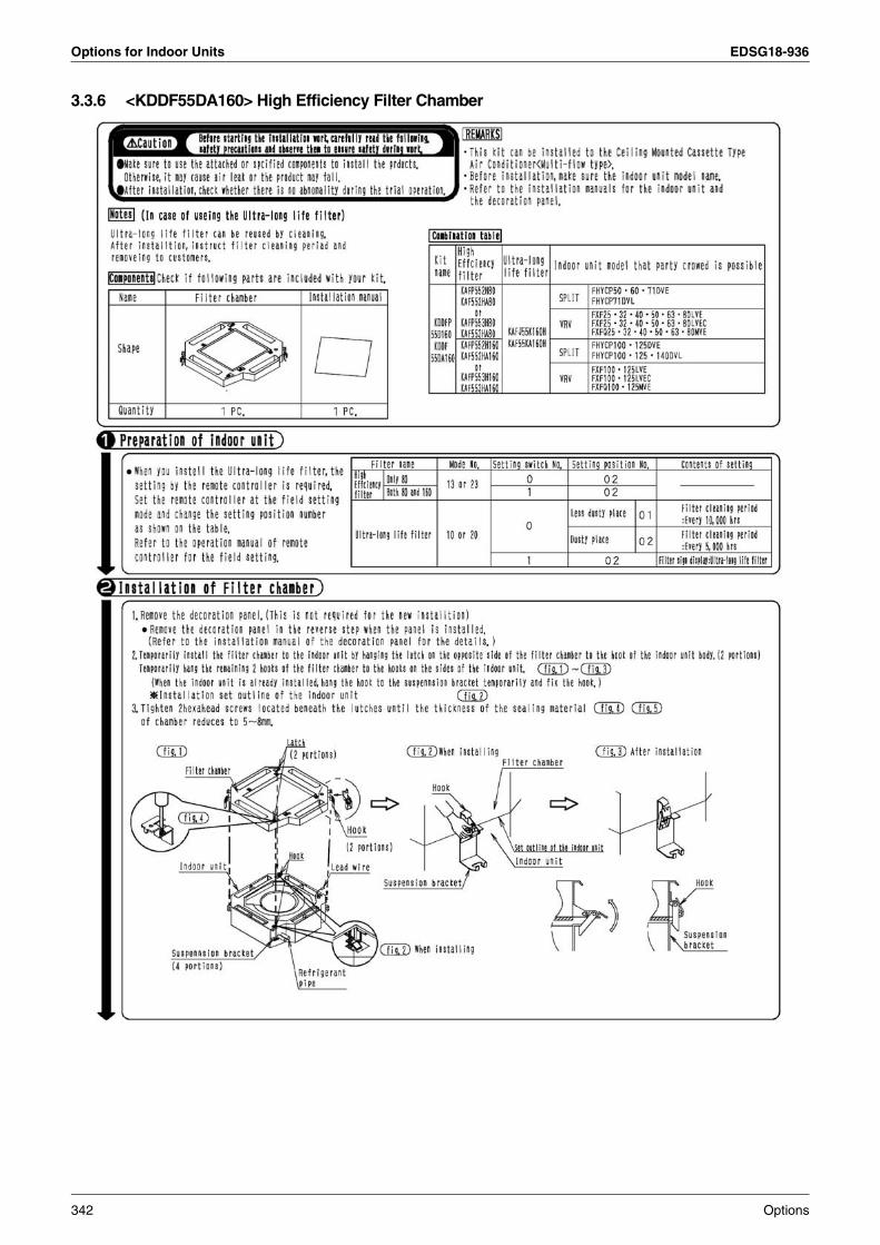
Options for Indoor Units EDSG18-936
3.3.6 <KDDF55DA160> High Efficiency Filter Chamber
342 Options
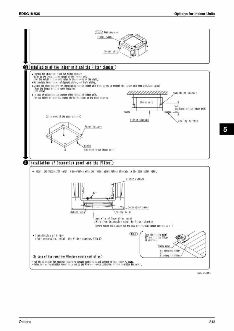
EDSG18-936 Options for Indoor Units
5
Options 343
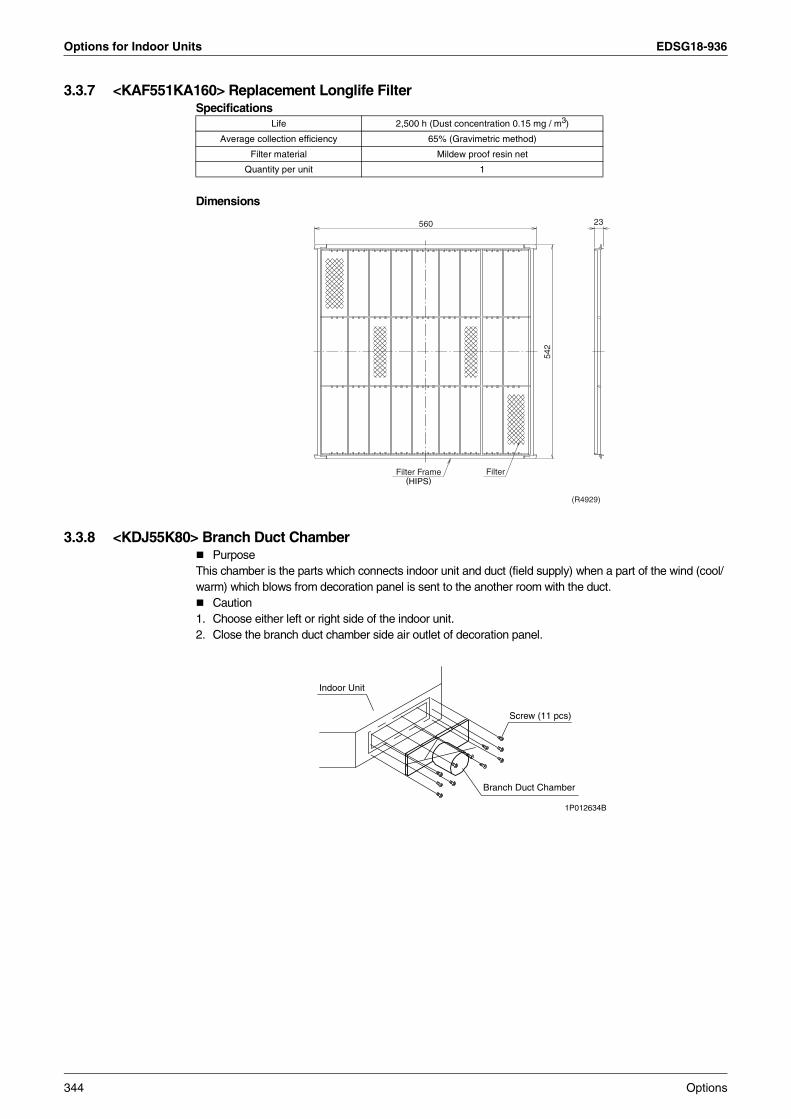
Options for Indoor Units EDSG18-936
3.3.7 <KAF551KA160> Replacement Longlife FilterSpecifications
Dimensions
3.3.8 <KDJ55K80> Branch Duct ChamberPurpose
This chamber is the parts which connects indoor unit and duct (field supply) when a part of the wind (cool/warm) which blows from decoration panel is sent to the another room with the duct.
Caution1. Choose either left or right side of the indoor unit.2. Close the branch duct chamber side air outlet of decoration panel.
Life 2,500 h (Dust concentration 0.15 mg / m3)
Average collection efficiency 65% (Gravimetric method)
Filter material Mildew proof resin net
Quantity per unit 1
Filter Frame(HIPS)
560
Filter
542
23
(R4929)
Indoor Unit
Screw (11 pcs)
Branch Duct Chamber
1P012634B
344 Options

EDSG18-936 Options for Indoor Units
5
3.4 Ceiling Mounted Built-in Type
3.4.1 <KTB25KA80W> Service Access PanelSpecifications
Dimension
Filter Chamber (For Bottom Suction)
Air Suction Canvas
Half Panel
Access Panel
High Efficiency Filter (65%, 95%)
Long Life Replacement Filter
Filter Chamber (For Rear Suction)
Air Suction Flange
Screening Door
(R4915)
ModelItem KTB25KA80W
Color White
Options 345
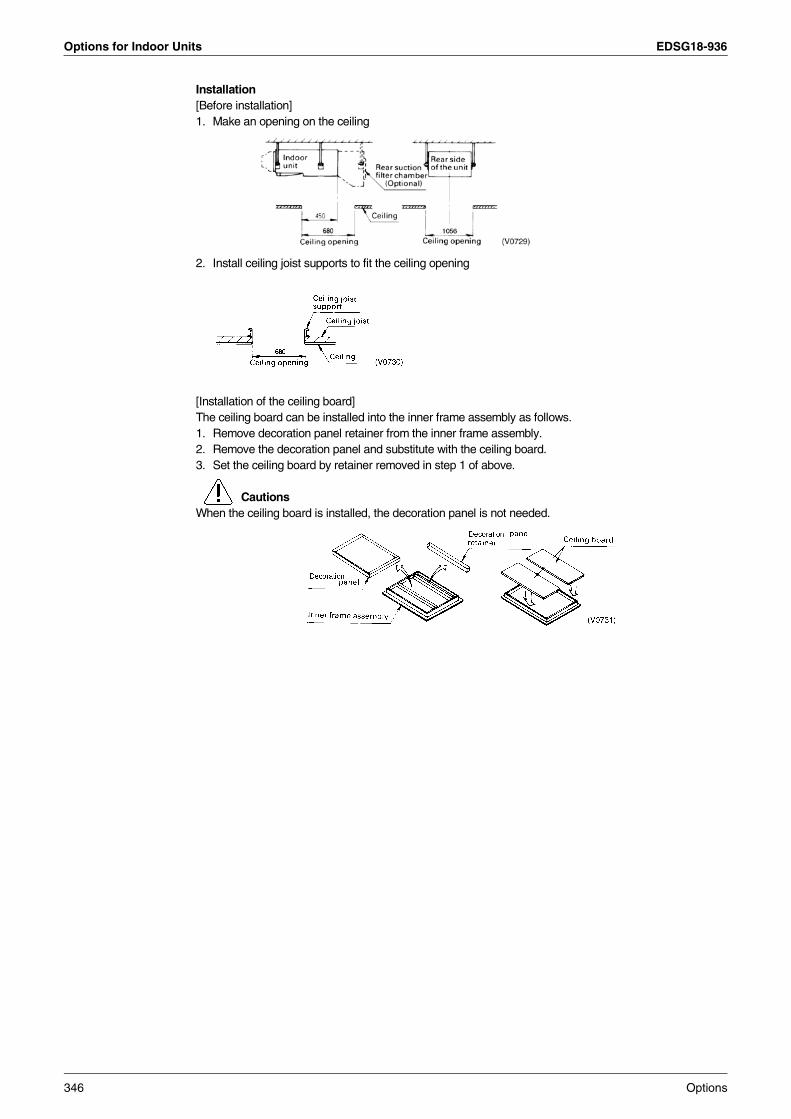
Options for Indoor Units EDSG18-936
Installation[Before installation]1. Make an opening on the ceiling
2. Install ceiling joist supports to fit the ceiling opening
[Installation of the ceiling board]The ceiling board can be installed into the inner frame assembly as follows.1. Remove decoration panel retainer from the inner frame assembly.2. Remove the decoration panel and substitute with the ceiling board.3. Set the ceiling board by retainer removed in step 1 of above.
CautionsWhen the ceiling board is installed, the decoration panel is not needed.
346 Options
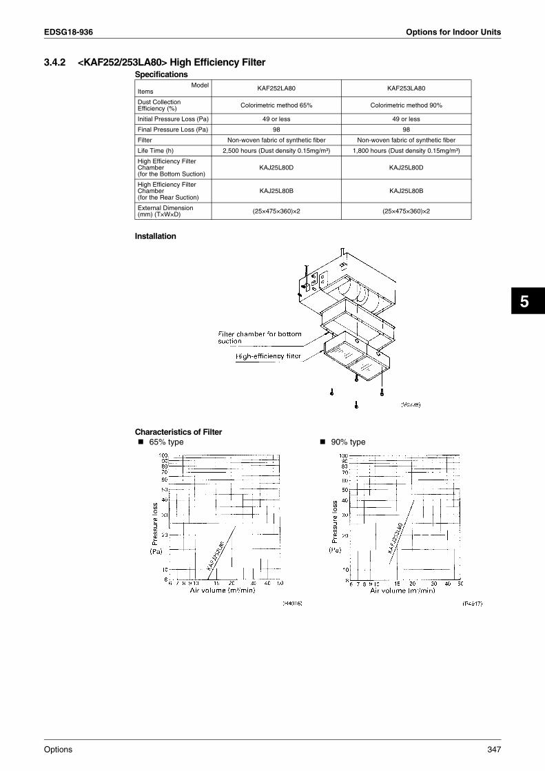
EDSG18-936 Options for Indoor Units
5
3.4.2 <KAF252/253LA80> High Efficiency FilterSpecifications
Installation
Characteristics of Filter
ModelItems KAF252LA80 KAF253LA80
Dust Collection Efficiency (%) Colorimetric method 65% Colorimetric method 90%
Initial Pressure Loss (Pa) 49 or less 49 or less
Final Pressure Loss (Pa) 98 98
Filter Non-woven fabric of synthetic fiber Non-woven fabric of synthetic fiber
Life Time (h) 2,500 hours (Dust density 0.15mg/m³) 1,800 hours (Dust density 0.15mg/m³)
High Efficiency Filter Chamber(for the Bottom Suction)
KAJ25L80D KAJ25L80D
High Efficiency Filter Chamber(for the Rear Suction)
KAJ25L80B KAJ25L80B
External Dimension (mm) (T×W×D) (25×475×360)×2 (25×475×360)×2
65% type 90% type
Options 347

Options for Indoor Units EDSG18-936
3.4.3 <KAFJ251K80> Replacement Longlife FilterSpecifications
Characteristics of filter
3.4.4 <KSA-25KA80> Canvas Duct (Air Suction Canvas)Specifications
Installation
3.4.5 <KDAJ25KA71> Adaptor for DischargeSpecifications
ModelItem KAFJ251K80
Average Efficiency (%) 50% (Gravity method)
Pressure Loss (Pa)
Initial 9.8
Final 49
Materials Mildew Proof Resin Net
Number Required per Model 2
Life Time (h) 2,500 hours (dust particle concentration at 0.15 mg/m³)
ModelItem KSA-25KA80
Dimensions (mm)
H 255
W 1000
D 405
Canvas Duct TOYOBO·SL1000·SIMVER·Flame resistant
ModelItem KDAJ25KA71
Connection Dia. (φmm) φ200×2 port
348 Options

EDSG18-936 Options for Indoor Units
5
3.4.6 <KAJ25L80B> Filter Chamber for Rear Suction This kit will be used for the rear-suction type when the high efficiency filter or the long life filter will be built in.
Installation
Be sure to remove the long life filter and attach the rear-suction type's sealing plate there when the filter chamber (for the rear-suction type) must be installed.
Note:Refer to the appearance figure of optional accessory describing later for further details.
Options 349

Options for Indoor Units EDSG18-936
3.4.7 <KAJ25L80D> Filter Chamber for Bottom Suction
Dimension
Installation
Note:Refer to the appearance figure of optional accessory describing later for further details.
350 Options

EDSG18-936 Options for Indoor Units
5
3.4.8 <KDJ2507K80> Flange for Suction When this kit will be used, the rear suction type's sealing plate will be required separately.
Specifications
Example of Installation
3.4.9 <KBBJ25KA80> Blind Board Specifications
Dimension
Installation
ModelKDJ2507K80
Item
Dimensions (mm) W 977
H 278
D 25
Size of Connecting Duct (mm)
W 927
L 228
Materials Galvanized steel plate
ModelItem KBBJ25KA80
Dimensions (mm) W 985
D 404
H 10
Materials Galvanized Steel Plate
Options 351
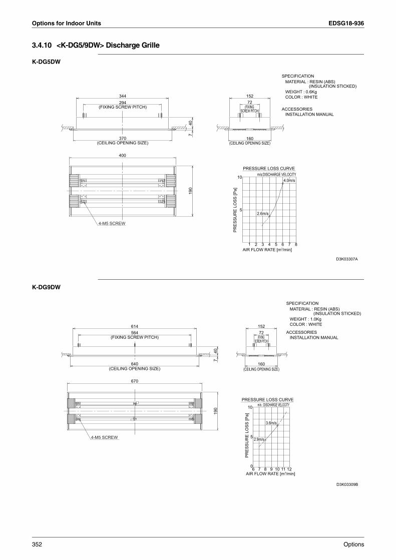
Options for Indoor Units EDSG18-936
3.4.10 <K-DG5/9DW> Discharge Grille
K-DG5DW
K-DG9DW
4-M5 SCREW
(CEILING OPENING SIZE)
(FIXING SCREW PITCH)
400
370
294344
740
190
(CEILING OPENING SIZE)
(FIXING SCREW PITCH)
PRES
SUR
E LO
SS [P
a]
10
160
5
15272
1 2
PRESSURE LOSS CURVE
AIR FLOW RATE [m3/min]3
2.6m/s
4 5
m/s:DISCHARGE VELOCITY
6
4.0m/s
7 8
ACCESSORIES INSTALLATION MANUAL
SPECIFICATION MATERIAL : RESIN (ABS) (INSULATION STICKED) WEIGHT : 0.6Kg COLOR : WHITE
D3K03307A
4-M5 SCREW
(FIXING SCREW PITCH)
(CEILING OPENING SIZE)
614
670
640
564
407
190
(CEILING OPENING SIZE)
(FIXING SCREW PITCH)
160
15272
10
PRES
SUR
E LO
SS [P
a]
0
5
6
PRESSURE LOSS CURVE
2.9m/s
7AIR FLOW RATE [m3/min]
8
3.6m/s
9
m/s : DISCHARGE VELOCITY
10 11
ACCESSORIES INSTALLATION MANUAL
SPECIFICATION MATERIAL : RESIN (ABS) (INSULATION STICKED) WEIGHT : 1.0Kg COLOR : WHITE
12
D3K03309B
352 Options
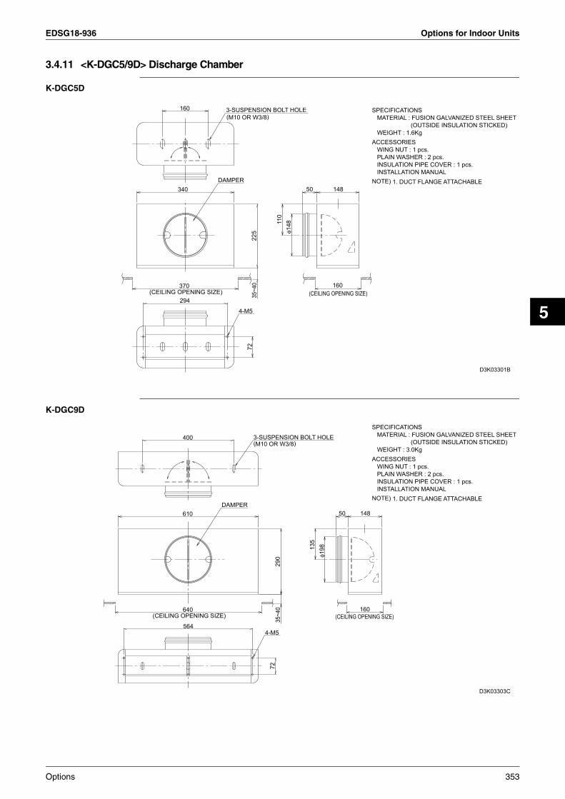
EDSG18-936 Options for Indoor Units
5
3.4.11 <K-DGC5/9D> Discharge Chamber
K-DGC5D
K-DGC9D
(CEILING OPENING SIZE)
160
340
370
294
DAMPER
3-SUSPENSION BOLT HOLE(M10 OR W3/8)
4-M5
7222
535
~40
110
φ148
50
(CEILING OPENING SIZE)160
148NOTE) 1. DUCT FLANGE ATTACHABLE
SPECIFICATIONS MATERIAL : FUSION GALVANIZED STEEL SHEET (OUTSIDE INSULATION STICKED) WEIGHT : 1.6KgACCESSORIES WING NUT : 1 pcs. PLAIN WASHER : 2 pcs. INSULATION PIPE COVER : 1 pcs. INSTALLATION MANUAL
D3K03301B
(CEILING OPENING SIZE)
610
400
640
564
DAMPER
3-SUSPENSION BOLT HOLE(M10 OR W3/8)
4-M5
7229
035
~40
135
φ198
50
(CEILING OPENING SIZE)160
148
D3K03303C
NOTE) 1. DUCT FLANGE ATTACHABLE
SPECIFICATIONS MATERIAL : FUSION GALVANIZED STEEL SHEET (OUTSIDE INSULATION STICKED) WEIGHT : 3.0KgACCESSORIES WING NUT : 1 pcs. PLAIN WASHER : 2 pcs. INSULATION PIPE COVER : 1 pcs. INSTALLATION MANUAL
Options 353
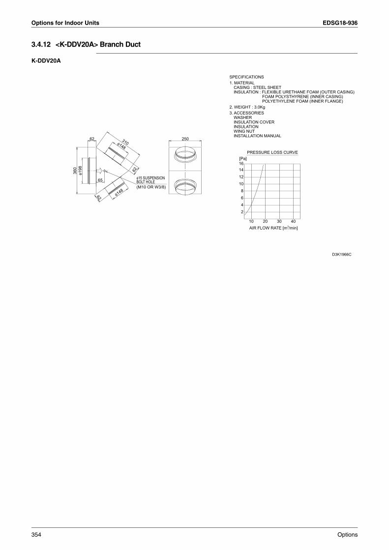
Options for Indoor Units EDSG18-936
3.4.12 <K-DDV20A> Branch Duct
K-DDV20A
360
φ198
62
62
65
φ148
φ148310
62
φ15 SUSPENSION BOLT HOLE(M10 OR W3/8)
250
SPECIFICATIONS1. MATERIAL
CASING : STEEL SHEETINSULATION : FLEXIBLE URETHANE FOAM (OUTER CASING)
FOAM POLYSTHYRENE (INNER CASING)POLYETHYLENE FOAM (INNER FLANGE)
2. WEIGHT : 3.0Kg3. ACCESSORIES
WASHERINSULATION COVERINSULATIONWING NUTINSTALLATION MANUAL
[Pa]
1012
1614
8
46
2
10AIR FLOW RATE [m3/min]
20
PRESSURE LOSS CURVE
30 40
D3K1966C
354 Options

EDSG18-936 Control Devices
5
4. Control Devices4.1 <DCS302CA61> Central Remote Controller
4.1.1 Applied Model
4.1.2 Specifications / Dimensions
64 groups (zones) of indoor units can be controlled individually same as LCD Remote controller.
Max.64 groups (128 indoor units controllable)Max. 128 groups (128 indoor units) are controllable by using 2 central remote controllers, which can control from 2 different places.Zone controlMalfunction code displayMax. wiring length 1,000 m (Total : 2,000 m)Combination with Unified ON/OFF controller, schedule timer and BMS systemAirflow volume and direction can be controlled individually for indoor units in each group operation. Ventilation volume and mode can be controlled for Heat Reclaim Ventilation (HRV).Up to 4 Operation/Stop pairs can be set per day by connecting a schedule timer.
Applied model Remark
SkyAir series Interface adaptor (DTA112BA51) is required for each indoor unit.
Residential Air conditioner Wiring adaptor (KRP928B2S) is required for each indoor unit.
SPECIFICATIONS
Specifications
Outline drawings
When using this unit, an electric parts box of KJB311AA is required.For installation, a steel electric parts box to be embedded is mandatory.
Power supply 1 ~ 50/60Hz, 100V – 240V
Power consumption Max. 8W
Forced ON/OFF inputContinuous “a” contactContact current: approximately 10mA
Size 180 (W) × 120 (H) × 64.5 (D)
Weight 420g
180
120
71
16 48.5
Options 355

Control Devices EDSG18-936
4.1.3 Installation Manual
Please read these “SAFETY CONSIDERATIONS” carefully before installing air conditioning equipment and be sure to install it correctly. After completing the installation, make sure that the unit operates properly during the start-up operation.Please instruct the customer on how to operate the unit and keep it maintained.Also, inform customers that they should store this installation manual along with the operation manual for future reference.This air conditioner comes under the term “appliances not accessible to the general public”.
WARNING ...... Indication a potentially hazardous situation which, if not avoided, could result in death or serious injury. CAUTION ....... Indication a potentially hazardous situation which, if not avoided, may result in minor or moderate injury. It may also be
used to alert against unsafe practices. NOTE ............. Indication situation that may result in equipment or property-damage-only accidents.
WARNINGAsk your dealer or qualified personnel to carry out installation work. Do not try to install the machine by yourself.Improper installation may result in water leakage, electric shocks or fire.
Perform installation work in accordance with this installation manual.Improper installation may result in water leakage, electric shocks or fire.
Be sure to use only the specified accessories and parts for installation work.Failure to use the specified parts may result in water leakage, electric shocks, fire or the unit falling.
Carry out the specified installation work after taking into account strong winds, typhoons or earthquakes.Improper installation work may result in the equipment falling and causing accidents.
Make sure that a separate power supply circuit is provided for this unit and that all electrical work is carried out by qualified personnel according to local laws and regulations and this installation manual.An insufficient power supply capacity or improper electrical construction may lead to electric shocks or fire.
Make sure that all wiring is secured, the specified wires and used, and no external forces act on the terminal connections or wires.Improper connections or installation may result in fire.
When wiring the power supply and connecting the remote controller wiring and transmission wiring, position the wires so that the electric parts box lid can be securely fastened.Improper positioning of the electric parts box lid may result in electric shocks, fire or the terminals overheating.
Before touching electrical parts, turn off the unit.
Ground the air conditioner. Do not connect the ground wire to gas or water pipes, lightning rod or a telephone ground wire.Incomplete grounding may result in electric shocks.
When installing or relocating the system, be sure to keep the refrigerant circuit free from substances other than the specified refrigerant (R410A), such as air.
Do not reconstruct or change the settings of the protection devices.If the pressure switch, thermal switch, or other protection device is shorted and operated forcibly, or parts other than those specified by Daikin are used, fire or explosion may result.
Do not touch the switch with wet fingers.Touching a switch with wet fingers can cause electric shock.
Install an leak circuit breaker, as required. If an leak circuit breaker is not installed, electric shock may result.
Do not install the air conditioner or the remote controller in the following locations: (a) where a mineral oil mist or an oil spray or vapor is produced, for example in a kitchen
Plastic parts may deteriorate and fall off or result in water leakage. (b) where corrosive gas, such as sulfurous acid gas, is produced
Corroding copper pipes or soldered parts may result in refrigerant leakage. (c) near machinery emitting electromagnetic waves
Electromagnetic waves may disturb the operation of the control system and result in a malfunction of the equipment. (d) where flammable gases may leak, where there are carbon fiber or ignitable dust suspensions in the air, or where volatile flammables
such as thinner or gasoline are handled. Operating the unit in such conditions may result in fire.
CISPR 22 Class A Warning.This is a class A product. In a domestic environment this product may cause radio interference in which case the user may be required to take adequate measures.
Meaning of warning, caution and note symbols.
356 Options

EDSG18-936 Control Devices
5
CAUTIONBe very careful about product transportation.
Safely dispose of the packing materials.Packing materials, such as nails and other metal or wooden parts, may cause stabs or other injuries.Tear apart and throw away plastic packaging bags so that children will not play with them. If children play with a plastic bag which was not torn apart, they face the risk of suffocation.
Do not turn off the power immediately after stopping operation. Always wait at least five minutes before turning off the power. Otherwise, water leakage and trouble may occur.
NOTEInstall the indoor and outdoor units, power supply wiring and connecting wires at least 3.5ft. away from televisions or radios in order to prevent image interference or noise. (Depending on the radio waves, a distance of 3.5ft. may not be sufficient enough to eliminate the noise.)
Remote controller (wireless kit) transmitting distance can result shorter than expected in rooms with electronic fluorescent lamps.(inverter or rapid start types)Install the indoor unit as far away from fluorescent lamps as possible.
This unit is a class A product.In a domestic environment this product may cause radio interference in which case the user may be required to take adequate measures.
Dismantling of the unit, treatment of the refrigerant, oil and eventual other parts, should be done in accordance with the relevant local and national regulations.
Options 357

Control Devices EDSG18-936
Check the following components are included in this optional accessory before installation.
When using this optional accessory an electric parts box of KJB311AA is required.For installation, a steel electric parts box to be embedded is necessary.
* DCS302CA61 includes only one installation manual.
COMPONENTS1
Installation screw (M4 × 16) 414
Operation manualInstallation manual*
Body
With the central remote controller, unified operation/stop is possible with up to a maximum 64 groups of indoor units. When using 2 central remote controllers, unified operation is possible with up to a maximum 128 groups.With this optional accessory, setting of control modes including operation, stop, operation controlled by timer, and ON/OFF control possible/impossible by remote controller can be set individually by zones while it enables to control and display the operation state such as set temperature.It can be connected with the external key system, host computer monitor panel, etc., through forced OFF input (no-voltage normally open contactor).A zone is a one or more groups together. In general, the same settings are used throughout a zone.
The central remote controller and the separately sold remote control adapter circuit board or group remote control adapter cannot be used together. See the D-BACS design guide for details.
SYSTEM CONFIGURATION2
When using 1 central •
•
remote controller
When using 2 central remote controller
Forced OFF input
(1) Open the upper part of remote controller. Insert a – screwdriver(2 locations) into the recess between the upper part and the lower part of remote controller and twist thescrewdriver lightly.
(2) Open the upper part of remote controller and install theElectric parts box with the attached installation screws
(M4 × 16).
NOTE) Suitable length of the electric wire is about 160mm. (from electric parts box)If it is difficult to contain a long wiring, strip the sheathed part of the wiring.
INSTALLATION3
PC board is attached with both the upper and lower part of remote controller. Do not damage the board with the screwdriver.
– screwdriver
(2 locations)
Power supply wire
Installation screws(4)
Do not contain the strong current electric wire and the weak current electric wire in the same conduit tube.
Weak current electric wire
Electric parts box (KJB311AA)
Conduit tube
Electric parts box
Approx. 160mm
Forced ON/OFF command should be connected to one of the two units.
Host computermonitor panel
Host computermonitor panel
Central remotecontroller
Central remotecontroller
Max. of 64 groups
Group No.1-00
Group No.1-15
Group No.2-00
Group No.4-15
Group No.1-00
Group No.1-15
Group No.2-00
Group No.4-15
Group No.5-00
Group No.5-15
Group No.6-00
Group No.8-15
Max. of 128 groups
Forced OFFinput
Outdoorunit
Outdoorunit
Outdoorunit
358 Options

EDSG18-936 Control Devices
5
(1) Connector for setting master controller (X1A) (Provided with connector at factory set)When using only 1 central remote controller, do not disconnect the connector for setting master controller. (Use the unit with •
•
the connector in the state in which it was delivered.)When using multiple central remote controllers, or using the central remote controller in conjunction with the optional controllers for centralized control, makes settings as indicated in the below table.
4 INITIAL SETTING Setting (1) through (3) are initialized when power is turned ON, therefore complete settings BEFORE activating the power. (The positions of connectors and switches used for settings in this section are shown in Fig. 1.)
Pattern of connection of optional controllers for centralized control
Central remote controller Unified ON/OFF controller Schedule timer
11 to 161 to 4
1
Connector for setting master controller (X1A) Setting, Removed
Central remote controller
Set one to “Used” and allthe rest to “Not used” Set all to “Not used”
Unified ON/OFF controller Schedule timer
“Not used”“Not used”
(3) MAIN/SUB changeover switch settingWith two central remote controllers, centralized control (indoor units) is possible from different locations. In this kind of set-up, it is necessary to set the MAIN/SUB changeover switch.
One of the two central remote controllers (1) . (2) is set to “MAIN” while the other is set to “SUB”.
(4) Setting of the sequential operation function The central remote controller is equipped with a sequential operation function that sequentially turns indoor units on in 2-second intervals during unified operation. (Sequential operation is factory set to “ON.”) To switch sequential operation ON or OFF, set as follows.
(Remove all the connectors for the central remote controller, the on/off controller, and the schedule timer when using the unit together with the intelligent Touch Controller, BACnet Gateway, the DMS interface, or the parallel interface station.)
SS3 settingSETTING EACH ADDRESS5-00~ 8-15
5-00~ 8-15
Indoor unit address
To control indoor units from group Nos. 1-00 through 4-15
SS3 setting Indoor unit address
To control indoor unitsfrom group Nos. 5-00 through 8-15
(2) Address settingTwo central remote controllers can be used as shown in 2 SYSTEM CONFIGURATION , to control anywhere up to a max. 128 groups of indoor units. In this case, group address must be set. This is done with the switch for setting each address (SS3).
SETTING EACH ADDRESS
Max. 64 groups
Group No.1-00
Group No.1-15
Group No.2-00
Group No.4-15Central remote
controller (2)Central remotecontroller (1)
Sequential operation“ON”
Sequential operation“OFF”
While holding down the unified start button, perform forced reset.
While holding down the unified stop button,perform forced reset.
(Factory set)
(5) Forced reset switch When changing the setting of the connector for setting master controller, etc., you can reset simply by setting it to the reset side once and returning to the normal side, without turning the power OFF.(For normal operation, set the switch to the normal side.)
NOTE: The sequential operation function is designed to reduce the load on the power supply equipment, but does not guarantee that compressors will not be started simultaneously. You cannot therefore count on a capacity reduction effect by power supply equipment breaker selection.
Connector for settingmaster controller
Switch for settingeach address
MAIN/SUBchangeover switch
Forced reset switch
Reset sideNormal side(Factory set)
RE
SE
T
Fig. 1
OF
FO
N
RE
SE
TO
FF
ON
Outdoorunit
Options 359
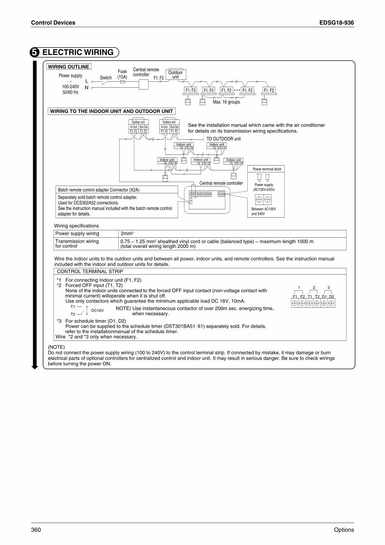
Control Devices EDSG18-936
ELECTRIC WIRING5WIRING OUTLINE
Power supply~
100-240V50/60 Hz
WIRING TO THE INDOOR UNIT AND OUTDOOR UNIT
Wiring specifications
Power supply wiring 2mm2
0.75 – 1.25 mm2 sheathed vinyl cord or cable (balanced type) – maximum length 1000 m (total overall wiring length 2000 m)
Transmission wiring for control
CONTROL TERMINAL STRIP
Wire the indoor units to the outdoor units and between all power, indoor units, and remote controllers. See the instruction manual included with the indoor and outdoor units for details.
*1 For connecting Indoor unit (F1, F2)*2 Forced OFF input (T1, T2)
None of the indoor units connected to the forced OFF input contact (non-voltage contact with minimal current) willoperate when it is shut off.Use only contactors which guarantee the minimum applicable load DC 16V, 10mA.
*3 For schedule timer (D1, D2)Power can be supplied to the schedule timer (DST301BA51. 61) separately sold. For details, refer to the installationmanual of the schedule timer.
Wire *2 and *3 only when necessary.
(NOTE)Do not connect the power supply wiring (100 to 240V) to the control terminal strip. If connected by mistake, it may damage or burn electrical parts of optional controllers for centralized control and indoor unit. It may result in serious danger. Be sure to check wirings before turning the power ON.
Outdoor unit
F1, F2 F1, F2 F1, F2 F1, F2
Outdoor unit
Central remote controller
In-Out Out-Out Out-OutIn-Out
Indoor unit
Indoor unit Indoor unit
Indoor unitIndoor unit
TO OUTDOOR unit
N F1 F2P
N F1 F2P N F1 F2P N
N
F1 F2P
F1 F2P
F1
CN2
F2
See the installation manual which came with the air conditioner for details on its transmission wiring specifications.
Batch remote control adapter Connector (X2A)
Separately sold batch remote control adapter.Used for DCS302A52 connections.See the instruction manual included with the batch remote control adapter for details.
Power terminal block
Power supply(AC100V-240V)
Between AC100V and 240V
NOTE) Use instantanecous contactor of over 200m sec. energizing time, when necessary.
T1DC16V
T2
F1
1 2 3
F2 T1 T2 D1 D2
Central remote controller Outdoor
unit
Max. 16 groups
F1, F2 F1, F2 F1, F2F1, F2 F1, F2
F1, F2LN
SwitchFuse(15A)
360 Options

EDSG18-936 Control Devices
5
Set the group number of each group of the indoor unit from the remote controller. (In case of no remote controller, also connect the remote controller and set the group No. Then, remove the remote controller.)(1) Turn ON the power of the indoor unit and central remote controller.
(Unless the power is ON, no setting can be made.)Check that the installation and electrical wiring are correct before turning the power supply ON.(When the power supply is turned ON, all LCD appear once and the unit may not accept the operation for about one minute with the display of “ ”.)
NOTES) For simplified remote controller, see the installation table.See the instruction manuals which came with the Ventiair and adapters (i.e., multi-purpose adapters) for details on their Group No. settings.
NOTICE Enter the group No. and installation place of the indoor unit into the installation table in the operation manual. Be sure to keep the operation manual for maintenance.
(2) While in the normal mode, hold down the “ ” button for a minimum of 4 seconds.The remote controller will enter the FIELD SET MODE.
(3) Select the MODE No. “ ” with the “ ” button.
(4) Use the “ ” button to select the group No. for each group.
(Group numbers increase in the order of 1-00,1-01,...1-15, 2-00,...8-15.)
(5) Press “ ” to set the selected group No.
(6) Press “ ” to return to the NORMAL MODE.
6 SETTING GROUP NO. FOR CENTRALIZED CONTROL
GROUP NO.
MODE NO.
FIELD SETMODE
TEST
SETTING
342.6
5
Before starting test operation, check that the power is supplied to the indoor and outdoor units, and central remote controller.
(1) Select the display “INDIVIDUALLY”
Press “ ” button to display “INDIVIDUALLY”
(2) Select the group to be tested.
Select the group No. with “ ” “ ” “ ” “ ” button.
(3) Press “ ” button to select the test operation mode.
“ TEST ” is displayed.
“ ” is displayed on the remote controller.
(4) Press “ ” button within 10 seconds after entering into the test operation mode.
Operation the unit for 30 minutes.
When pressing the “ ” button, the unit stops operating.
If the operation lamp flashes, it indicates a malfunction.Call the group of flashing display, confirm malfunction code, and check the source of malfunction.(The operation manual lists all error codes, so refer to it.)
NOTES For test operation, refer to the installation manual of the outdoor unit.After turning the power supply ON, if the unit does not accept operation for two minutes or more with the display of “ ”, check the following points.
Check that setting of the connector for setting master controller is correct.Check that the group No. for centralized control has been set.
7 TEST OPERATION (Perform a test operation in the individual screen before registering zones.)
3
2 41
TEST
TEST
2P162816-1
Options 361

Control Devices EDSG18-936
4.1.4 Operation Manual
3
Fig. 1
Fig. 3
Fig. 2
Fig. 4
362 Options
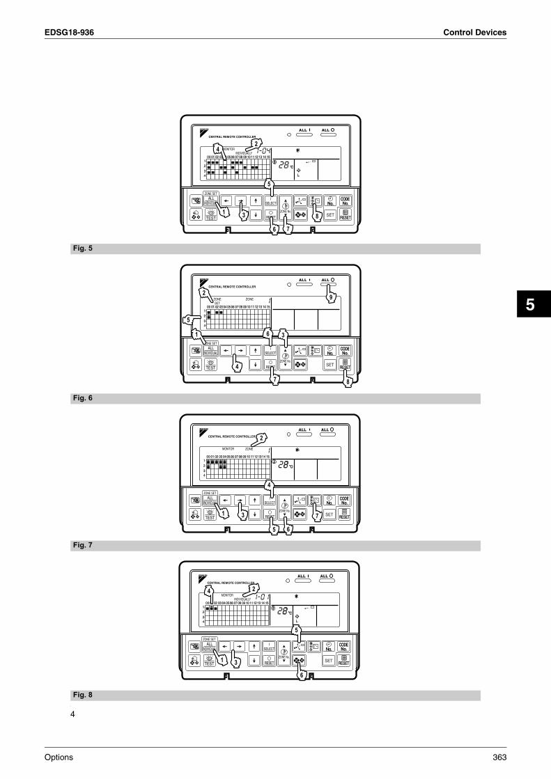
EDSG18-936 Control Devices
5
4
Fig. 6
Fig. 5
Fig. 8
Fig. 7
Options 363
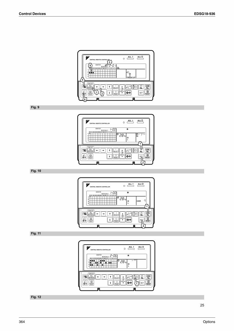
Control Devices EDSG18-936
25
Fig. 9
Fig. 12
Fig. 10
Fig. 11
1
6
5
42
3
364 Options
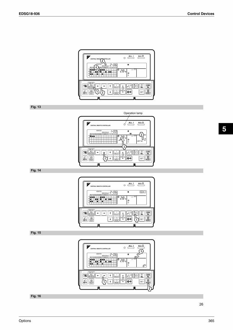
EDSG18-936 Control Devices
5
26
Fig. 14
Fig. 13
Fig. 16
Fig. 15
Options 365

Control Devices EDSG18-936
1
BEFORE USE
GENERAL DESCRIPTION OF SYSTEM
This central remote controller can monitor and control up to 64 indoor unit groups.Using two central remote controllers allows monitoring and controlling of up to 128 indoor unit groups.
Main Functions
1. Batch starting and stopping of indoor units connected to the central remote controller.
2. Handling of operation settings such as start/stop, timer operation, remote controller prohibition/permission, etc.,
and operation status settings such as temperature.
3. Operation status monitoring of operation mode, set temperature, etc.
4. Can be connected to an external central monitor panel and key system using the forced stop input
(non-voltage a connector).
• When using 1 central remote controller
• When using 2 central remote controllers
(The central remote controller and the separately sold remote control adapter circuit board or group remote con-
trol adapter cannot be used together.)
∗ GROUP OF INDOOR UNIT refers to the below.
1. A single indoor unit without remote controller
!
"
!
!
"##
!
"$
!
"##
!
%"$
!
$"##
!
$"$
!
&"##
!
"$
Remote controller not used
Indoor unit
A maximum of 16 units A maximum of 16 units
Remote controller
Remote controller
Two remote controllers
Two remote controllers
A single indoor unit without remote controller
Maximum of 16 indoor units, group-controlled by one or two remote controllers
A single indoor unit controlled by one or two remote controllers
366 Options

EDSG18-936 Control Devices
5
2
∗ Zone control from the central remote controllerZone control is available from the central remote controller. With it, it is possible to make unified settings for mul-tiple groups, so setting operations are greatly simplified.
• Any setting you make within a given zone will apply to all groups in the said zone.• A maximum of 64 zones can be set from a single central remote controller.
(Each zone contains a maximum of 64 groups.)• Zones can be set randomly from the central remote controller.
SAFETY CONSIDERATIONSPlease read these “SAFETY CONSIDERATIONS” carefully before installing air conditioning equipment and be sure to install it correctly. After completing the installation, make sure that the unit operates properly during the start-up operation.Please instruct the customer on how to operate the unit and keep it maintained.Also, inform customers that they should store this installation manual along with the operation manual for future reference.This air conditioner comes under the term “appliances not accessible to the general public”.
Meaning of warning, caution and note symbols.
WARNING ....Indicates a potentially hazardous sit-
uation which, if not avoided, could result in death or serious injury.
CAUTION .... Indicates a potentially hazardous
situation which, if not avoided, may result in minor or moderate injury. It may also be used to alert against unsafe practices.
NOTE........... Indicates situation that may result
in equipment or property-damage-only accidents.
Keep these warning sheets handy so that you can refer to them if needed.Also, if this equipment is transferred to a new user, make sure to hand over this operation manual to the new user.
WARNING
In order to avoid electric shock, fire or injury, or if you detect any abnormality such as smell of fire, turn off power and call your dealer for instructions.
Ask your dealer for installation of the air conditioner.Incomplete installation performed by yourself may result in a water leakage, electric shock, and fire.
Ask your dealer for improvement, repair, and maintenance.Incomplete improvement, repair, and maintenance may result in a water leakage, electric shock, and fire.
Improper installation or attachment of equipment or accessories could result in electric shock, short-circuit, leaks, fire or other damage to the equipment. Be sure only to use accessories made by Daikin which are specifically designed for use with the equipment and have them installed by a professional.
Ask your dealer to move and reinstall the air con-ditioner or the remote controller. Incomplete installation may result in a water leakage, electric shock, and fire.
Never let the indoor unit or the remote controller get wet. It may cause an electric shock or a fire.
Never use flammable spray such as hair spray, lacquer or paint near the unit.It may cause a fire.
Never replace a fuse with that of wrong ampere ratings or other wires when a fuse blows out.Use of wire or copper wire may cause the unit to break down or cause a fire.
Never inspect or service the unit by yourself.Ask a qualified service person to perform this work.
Cut off all electric waves before maintenance.
Do not wash the air conditioner or the remote controller with excessive water.Electric shock or fire may result.
Do not install the air conditioner or the remote controller at any place where flammable gas may leak out.If the gas leaks out and stays around the air condi-tioner, a fire may break out.
Do not touch the switch with wet fingers.Touching a switch with wet fingers can cause electric shock.
CISPR 22 Class A Warning:This is a class A product. In a domestic environment this prod-uct may cause radio interference in which case the user may be required to take adequate measures.
Options 367

Control Devices EDSG18-936
5
CAUTION
After a long use, check the unit stand and fittingfor damage.If they are left in a damaged condition, the unit may fall and result in injury.
Do not allow a child to mount on the unit or avoid placing any object on it.Falling or tumbling may result in injury.
Do not let children play on and around the unit.If they touch the unit carelessly, it may result in injury.
Do not place a flower vase and anything contain-ing water.Water may enter the unit, causing an electric shock or fire.
Never touch the internal parts of the controller.Do not remove the front panel. Some parts inside are dan-gerous to touch, and a machine trouble may happen. For checking and adjusting the internal parts, contact your dealer.
Avoid placing the controller in a spot splashed with water.Water coming inside the machine may cause an electric leak or may damage the internal electronic parts.
Do not operate the air conditioner when using a room fumigation - type insecticide.Failure to observe could cause the chemicals to become deposited in the unit, which could endanger the health of those who are hypersensitive to chemicals.
Safely dispose of the packing materials.Packing materials, such as nails and other metal or wooden parts, may cause stabs or other injuries.Tear apart and throw away plastic packaging bags so that children will not play with them. If children play with a plastic bag which was not torn apart, they face the risk of suffocation.
Do not turn off the power immediately after stop-ping operation.Always wait at least five minutes before turning off the power. Otherwise, water leakage and trouble may occur.
The appliance is not intended for use by young children or infirm persons without supervision.
The remote controller should be installed in
such a way that children cannot play with it.
NOTE
Never press the button of the remote controller with a hard, pointed object.The remote controller may be damaged.
Never pull or twist the electric wire of the remote controller.It may cause the unit to malfunction.
Do not place the controller exposed to direct sunlight.The LCD display may get discolored, failing to dis-play the data.
Do not wipe the controller operation panel with benzine, thinner, chemical dustcloth, etc.The panel may get discolored or the coating peeled off. If it is heavily dirty, soak a cloth in water-diluted neutral detergent, squeeze it well and wipe the panel clean. And wipe it with another dry cloth.
Dismantling of the unit, treatment of the refriger-ant, oil and eventual other parts, should be done in accordance with the relevant local and national regulations.
CONTENTS
BEFORE USE ..................................................... 1
GENERAL DESCRIPTION OF SYSTEM .............. 1
SAFETY CONSIDERATIONS ....................... 2
FEATURES AND FUNCTIONS .................... 6
NAMES AND FUNCTIONS OF THE
OPERATING SECTION .................................. 7
OPERATION........................................................ 8
Individual screen, all screen, zone screen ............. 8
Batch operation and stop method ......................... 9
Group operation and stop method.......................... 9
Registering zones................................................... 9
Zone operation and stop method ......................... 10
Changing the fan direction and fan strength ........ 11
Changing the ventilation mode and
ventilation strength .............................................. 11
Timer Number Setting ......................................... 11
Setting the Operation Code.................................. 12
OPERATION MODE ........................................ 13
Setting operation mode .........................................16
Group monitoring ..................................................16
Error diagnosing function .....................................17
Setting master remote controller ..........................20
Display of time to clean .........................................21
INSTALLATION TABLE ................................ 22
OPTIONAL ACCESSORIES......................... 23
DOUBLE CENTRAL REMOTE
CONTROLLERS ............................................... 23
SPECIFICATIONS............................................ 24
Specifications .......................................................24
Outline drawings ..................................................24
Fig. 1, 2, 3, 4...............................................................3
Fig. 5, 6, 7, 8...............................................................4
Fig. 9, 10, 11, 12.......................................................25
Fig. 13, 14, 15, 16.....................................................26
368 Options

EDSG18-936 Control Devices
5
6
FEATURES AND FUNCTIONS
• Room air conditioners and multi-purpose air conditioners may also be connected by using separately-sold
adapter boards.
This may limit functionality, so consult the manuals that come with each adapter board.
Operation menuThis central remote controller can operate and stop machines by either group or zone.Batch operation and batch stop functions are also available. When used in combination with the schedule timer (optional accessory), timer operation and stop functions are available.
Various operation modes.You can operate the system from both this unit and the remote controller, so to enable various operation control patterns. Twenty different operation modes are available including five operation patterns:
1. Start/stop: remote controller prohibition, remote controller stop-only permission, central priority, after-press priority, remote controller permission timer
2. Operation modes: remote controller prohibition, remote controller permission
3. Set temperature: remote controller prohibition, remote controller permission
Zone control for simpler setting proceduresYou can control a maximum of 64 groups of indoor units by using this central remote controller. You don’t have to repeat the same setting operations by group because you can make each of the following settings by zone.A functions is available for setting all groups in one batch.
Operation modeControl modeSetting temperatureProgramming time No. (Used in conjunction with the
schedule timer)
Monitoring all indoor unit informationThe following information can be displayed by group.
Operation information such as operation mode, settemperature, etc., for indoor units
Maintenance information such as cleaning signs for filters or elements
Error codes and other malfunction diagnosis information
Function of refrigerant system displayThis display helps you understand, at a glance, the indoor units sharing the same outdoor unit and the particular indoor unit among them that is set as the master remote controller.
See page8—12.
See page8—16.
See page16—21.
See page 20.
See page 13—15.
Options 369

Control Devices EDSG18-936
7
NAMES AND FUNCTIONS OF THE OPERATING SECTION (Fig. 1, 2)
1UNIFIED OPERATION BUTTON
Press to operate all indoor units.
2UNIFIED STOP BUTTON
Press to stop all indoor units.
3OPERATION LAMP (RED)
Lit white any of the indoor units under control is in operation.
4
“ ” DISPLAY (REFRIGERANT SYSTEM DISPLAY)
This indication in the square is lit while the refrigerant system is being displayed.
5 “ ” DISPLAY (ZONE SETTING)
The lamp is lit while setting zones.
6“ ” DISPLAY (OPERATION MONITOR)
The lamp is lit while operation is being monitored.
7
“ ” “ ” “ ” DISPLAY
The status displays indicates either batch
functions or which zone or individual unit
(or group) are being used.
8OPERATION MONITOR
Each square displays the state corresponding to each group.
9“ ” “ ” “ ” “ ” “ ” “ ” “ ”DISPLAY (OPERATION MODE)
Displays operating state.
10
“ ” “ ” “ ” “ ” DISPLAY (VENTILATION CLEANING DISPLAY)
This is displayed when a Ventiair total enthalpy
heat exchanger unit or other such unit is
connected.
11
“ ” DISPLAY (INSPECTION/TEST)
Pressing the maintenance/test run button(for service) displays this. This button should not normally be used.
12
“ ” DISPLAY (TIME TO CLEAN)
It lights up when any individual unit (group) has reached the time for the filter or element to be cleaned.
INDIVIDUALLY
13
“ ” DISPLAY (COOLING/HEATING SELECTION PRIVILEGE NOT SHOWN)
For zones or individual units (groups) for which
this is displayed, cooling and heating cannot be
selected.
14
“ ” DISPLAY (UNDER HOST COMPUTER INTEGRATED CON-TROL)
While this display is lit up, no settings can be made. It lights up when the upper central machines are present on the same air conditioning network.
15“ ” DISPLAY (PRESET TEMPERATURE)
Displays the preset temperature.
16
“ ” DISPLAY (MALFUNCTION CODE)
This displays (flashes) the content of errors
when an error failure has occurred.
In maintenance mode, it displays the latest error content.
17
“NOT AVAILABLE” DISPLAY(NO FUNCTION DISPLAY)
If a function is not available in the indoor unit even if the button is pressed, “NOT AVAILABLE” is may be displayed for a few seconds.
18
“ ” DISPLAY (FAN DIRECTION SWING DISPLAY)
This displays whether the fan direction is fixed
or set to swing.
19
“ ” “ ” “ ” “ ” “ ” “ ”
DISPLAY (VENTILATION STRENGTH/SET FAN STRENGTH DISPLAY)
This displays the set fan strength.
20“ ” DISPLAY (TIME NO.)
Displays the operation timer No. when used in conjunction with the schedule timer.
370 Options
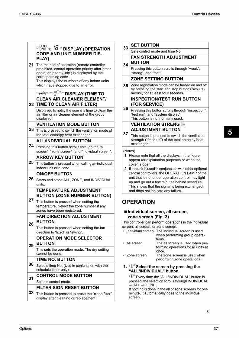
EDSG18-936 Control Devices
5
8
OPERATION
Individual screen, all screen,
zone screen (Fig. 3)This controller can perform operations in the individual
screen, all screen, or zone screen.
• Individual screen The individual screen is used when performing group opera-tions.
• All screen The all screen is used when per-forming operations for all units at once.
• Zone screen The zone screen is used when performing zone operations.
1. Select the screen by pressing the “ALL/INDIVIDUAL” button.
Every time the “ALL/INDIVIDUAL” button is pressed, the selection scrolls through INDIVIDUAL → ALL → ZONE.If nothing is done in the all or zone screens for one minute, it automatically goes to the individual screen.
21
“ ” DISPLAY (OPERATION CODE AND UNIT NUMBER DIS-PLAY)
The method of operation (remote controller prohibited, central operation priority after-press operation priority, etc.) is displayed by the corresponding code.This displays the numbers of any indoor units
which have stopped due to an error.
22
“ ” “ ” DISPLAY (TIME TO
CLEAN AIR CLEANER ELEMENT/
TIME TO CLEAN AIR FILTER)
Displayed to notify the user it is time to clean the air filter or air cleaner element of the group displayed.
23VENTILATION MODE BUTTON
This is pressed to switch the ventilation mode of
the total enthalpy heat exchanger.
24ALL/INDIVIDUAL BUTTON
Pressing this button scrolls through the “all
screen”, “zone screen”, and “individual screen”.
25ARROW KEY BUTTON
This button is pressed when calling an individual
indoor unit or a zone.
26ON/OFF BUTTON
Starts and stops ALL, ZONE, and INDIVIDUAL
units.
27
TEMPERATURE ADJUSTMENT
BUTTON (ZONE NUMBER BUTTON)
This button is pressed when setting the
temperature. Select the zone number if any
zones have been registered.
28
FAN DIRECTION ADJUSTMENT
BUTTON
This button is pressed when setting the fan
direction to “fixed” or “swing”.
29
OPERATION MODE SELECTOR
BUTTON
This sets the operation mode. The dry setting cannot be done.
30TIME NO. BUTTON
Selects time No. (Use in conjunction with the schedule timer only).
31CONTROL MODE BUTTON
Selects control mode.
32FILTER SIGN RESET BUTTON
This button is pressed to erase the “clean filter”
display after cleaning or replacement.
33SET BUTTON
Sets control mode and time No.
34
FAN STRENGTH ADJUSTMENT
BUTTON
Pressing this button scrolls through “weak”,
“strong”, and “fast”.
35
ZONE SETTING BUTTON
Zone registration mode can be turned on and off by pressing the start and stop buttons simulta-neously for at least four seconds.
36
INSPECTION/TEST RUN BUTTON
(FOR SERVICE)
Pressing this button scrolls through “inspection”, “test run”, and “system display”. This button is not normally used.
37
VENTILATION STRENGTH
ADJUSTMENT BUTTON
This button is pressed to switch the ventilation strength (“fresh up”) of the total enthalpy heat exchanger.
(Notes)
1. Please note that all the displays in the figure
appear for explanation purposes or when the
cover is open.
2. If the unit is used in conjunction with other optional
central controllers, the OPERATION LAMP of the
unit that is not under operation control may light
up and go out a few minutes behind schedule.
This shows that the signal is being exchanged,
and does not indicate any failure.
Options 371
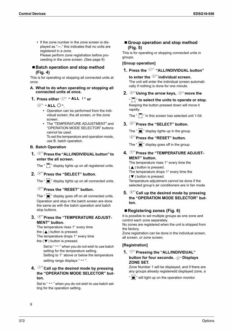
Control Devices EDSG18-936
9
• If the zone number in the zone screen is dis-
played as “---,” this indicates that no units are
registered in a zone.
Please perform zone registration before pro-
ceeding in the zone screen. (See page 9)
Batch operation and stop method
(Fig. 4)This is for operating or stopping all connected units at
once.
A. What to do when operating or stopping all connected units at once.
1. Press either “ ” or
“ ”.• Operation can be performed from the indi-
vidual screen, the all screen, or the zone
screen.
• The “TEMPERATURE ADJUSTMENT” and
“OPERATION MODE SELECTOR” buttons
cannot be used.
To set the temperature and operation mode,
use B. batch operation.
B. Batch Operation
1. Press the “ALL/INDIVIDUAL button” to
enter the all screen.
The “ ” display lights up on all registered units.
2. Press the “SELECT” button.
The “ ” display lights up on all connected units.
Press the “RESET” button.
The “ ” display goes off on all connected units.
Operation and stop in the batch screen are done
the same as with the batch operation and batch
stop buttons.
3. Press the “TEMPERATURE ADJUST-
MENT” button.The temperature rises 1° every time
the ( ) button is pressed.
The temperature drops 1° every time
the ( ) button is pressed.
Set to “ ” when you do not wish to use batch
setting for the temperature setting.
Setting to 1° above or below the temperature
setting range displays “ ”.
4. Call up the desired mode by pressing
the “OPERATION MODE SELECTOR” but-
ton.
Set to “ ” when you do not wish to use batch set-
ting for the operation setting.
Group operation and stop method
(Fig. 5)This is for operating or stopping connected units in
groups.
[Group operation]
1. Press the “ALL/INDIVIDUAL button”
to enter the individual screen.The unit will enter the individual screen automati-
cally if nothing is done for one minute.
2. Using the arrow keys, move the
“ ” to select the units to operate or stop.
Keeping the button pressed down will move it
rapidly.
The “ ” in this screen has selected unit 1-04.
3. Press the “SELECT” button.
The “ ” display lights up in the group.
Press the “RESET” button.
The “ ” display goes off in the group.
4. Press the “TEMPERATURE ADJUST-
MENT” button.The temperature rises 1° every time the
( ) button is pressed.
The temperature drops 1° every time the
( ) button is pressed.
Temperature adjustment cannot be done if the
selected group’s air conditioners are in fan mode.
5. Call up the desired mode by pressing
the “OPERATION MODE SELECTOR” but-
ton.
Registering zones (Fig. 6)It is possible to set multiple groups as one zone and
control each zone separately.
No zones are registered when the unit is shipped from
the factory.
Zone registration can be done in the individual screen,
all screen, or zone screen.
[Registration]
1. Pressing the “ALL/INDIVIDUAL”
button for four seconds. Displays
ZONE SET.Zone Number 1 will be displayed, and if there are
any groups already registeredd displayed zone, a
“ ” will light up on the operation monitor.
372 Options
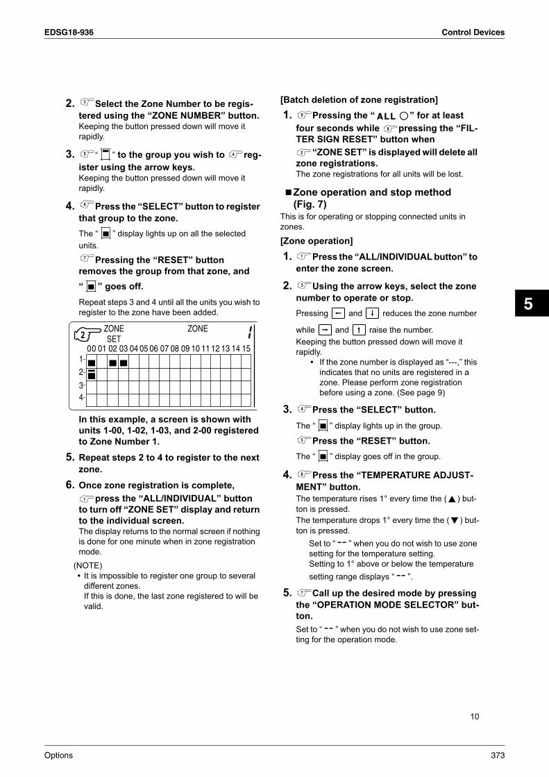
EDSG18-936 Control Devices
5
10
2. Select the Zone Number to be regis-
tered using the “ZONE NUMBER” button.Keeping the button pressed down will move it
rapidly.
3. “ ” to the group you wish to reg-
ister using the arrow keys.Keeping the button pressed down will move it
rapidly.
4. Press the “SELECT” button to register
that group to the zone.
The “ ” display lights up on all the selected
units.
Pressing the “RESET” button
removes the group from that zone, and
“ ” goes off.
Repeat steps 3 and 4 until all the units you wish to
register to the zone have been added.
In this example, a screen is shown with
units 1-00, 1-02, 1-03, and 2-00 registered
to Zone Number 1.
5. Repeat steps 2 to 4 to register to the next
zone.
6. Once zone registration is complete,
press the “ALL/INDIVIDUAL” button
to turn off “ZONE SET” display and return
to the individual screen.The display returns to the normal screen if nothing
is done for one minute when in zone registration
mode.
(NOTE)
• It is impossible to register one group to several
different zones.
If this is done, the last zone registered to will be
valid.
[Batch deletion of zone registration]
1. Pressing the “ ” for at least
four seconds while pressing the “FIL-
TER SIGN RESET” button when
“ZONE SET” is displayed will delete all
zone registrations.The zone registrations for all units will be lost.
Zone operation and stop method
(Fig. 7)This is for operating or stopping connected units in
zones.
[Zone operation]
1. Press the “ALL/INDIVIDUAL button” to
enter the zone screen.
2. Using the arrow keys, select the zone
number to operate or stop.
Pressing and reduces the zone number
while and raise the number.
Keeping the button pressed down will move it
rapidly.
• If the zone number is displayed as “---,” this
indicates that no units are registered in a
zone. Please perform zone registration
before using a zone. (See page 9)
3. Press the “SELECT” button.
The “ ” display lights up in the group.
Press the “RESET” button.
The “ ” display goes off in the group.
4. Press the “TEMPERATURE ADJUST-
MENT” button.
The temperature rises 1° every time the ( ) but-
ton is pressed.
The temperature drops 1° every time the ( ) but-
ton is pressed.
Set to “ ” when you do not wish to use zone
setting for the temperature setting.
Setting to 1° above or below the temperature
setting range displays “ ”.
5. Call up the desired mode by pressing
the “OPERATION MODE SELECTOR” but-
ton.
Set to “ ” when you do not wish to use zone set-
ting for the operation mode.
Options 373

Control Devices EDSG18-936
11
Changing the fan direction and fan
strength (Fig. 8)This changes the fan direction and strength settings in
the air conditioner.
Changing the fan direction and strength is done in the
individual screen.
[Registration]
1. Press the “ALL/INDIVIDUAL button”
to enter the individual screen.The unit will enter the individual screen automati-
cally if nothing is done for one minute.
2. Using the arrow keys, move the
“ ” to select the units to fan direction
adjustment or fan strength adjustment.Keeping the button pressed down will move it
rapidly.
3. Press the “FAN DIRECTION ADJUST-
MENT” button.This sets “fixed” or “swing” for the fan direction.
Press the “FAN STRENGTH ADJUST-
MENT” button.Pressing this button scrolls through “ ”, “ ”,
and “ ”.
Depending on the indoor unit, only “ ” and “ ”
may be available.
The functions included in the indoor units may vary.
Pressing a button for a function which is not available
will cause “NOT AVAILABLE” to be displayed.
Changing the ventilation mode and
ventilation strength (Fig. 9)This changes the ventilation mode and strength set-
tings in the total enthalpy heat exchanger.
Changing the ventilation mode and strength is done in
the individual screen.
[Registration]
1. Press the “ALL/INDIVIDUAL button” to
enter the individual screen.The unit will enter the individual screen automati-
cally if nothing is done for one minute.
2. Using the arrow keys, move the
“ ” to select the units to ventilation
mode or ventilation strength adjustment.Keeping the button pressed down will move it
rapidly.
3. Press the “VENTILATION MODE”
button.
It will scroll through “ ” → “ ” → “ ”
→ “ ”.
Press the “VENTILATION STRENGTH
ADJUSTMENT” button.
It will scroll through “ ” → “ ” → “ ” →
“ ” → “ ”.
The fresh up function may not be available
depending on the connected unit model.
The functions included in the indoor units may vary.
Pressing a button for a function which is not available
will cause “NOT AVAILABLE” to be displayed.
• Ventilation Mode and Amount
If these are changed using the remote controller
depending on the unit model, they cannot be dis-
played on the central remote controller.
To monitor the ventilation mode and amount, check
the values on the remote controller.
Timer Number Setting (Fig. 10)
(Only when used with the schedule timer)
Using this together with the schedule timer makes it
possible to set on and off times four times a day.
[Registration]
1. Pressing the “TIMER NO.” button
causes the number set for timer number 1
to blink.If no timer setting has been made
“ ” will be displayed.
Select the desired timer number
by pressing the “TIMER
NO.” button.
2. Once the desired timer number is
displayed, press the “SET” button.
Press the “SET” button
within 10 seconds after the timer
number is displayed.
The display will return to how it
was after 10 seconds.
The display for timer number 1
will stop blinking and then timer number 2 will start
blinking.
374 Options

EDSG18-936 Control Devices
5
12
3. Select the desired timer number by
pressing the “TIMER NO.” button.Once the desired timer number is
displayed, press the “SET”
button.
The display for timer number 2
will stop blinking.
The “ ” display will disappear
after 3 seconds.
Select “ ” in the timer number when you do not
wish to set a timer number.
It is possible to set only one timer number.
(The times for turning the unit(s) on and off twice a
day can be set with a single timer number.)
• Timer Number Setting
Group control: select the unit in the individual
screen and set the timer number.
Batch control: set the timer numbers for all con-
nected units.
Zone control: set the timer numbers for all
zone-registered units.
Call up the zones which you wish
to set in the zone screen and set
the timer numbers.
• Since the timer number will be set to after-
press priority, the timer number in the last
screen set will be valid for the connected
units.
Example 1
Setting timer number 1 for unit 1-00 to “1” and
timer number 2 to “2” in the individual screen and
then setting timer number 1 to “3” and timer
number 2 to “4” in the batch screen causes the
timer numbers for all units to be set, so timer
number 1 for unit 1-00 will be “3” and timer num-
ber 2 will be “4”.
Example 2
To prevent leaving units on, timer number 1 is
set to “5” in the batch screen.
Setting timer number 1 in zone number 1 to “ ”
in the zone screen after that will change the
timer number for zone number 1, so the setting
to prevent leaving the units on will be lost for
zone number 1 only.
If a timer number is set incorrectly by accident,
redo the setting in the desired screen.
• What happens when the timer number on
time and off time are set to the same time
When the on time and off time are set to the
same time for the same timer number, operation
does not change.
When the on time and off time are set to the
same time for different timer numbers, the off
time is given priority.
When using timer operation, make sure the
times do not overlap when setting the program of
the schedule timer.
Setting the Operation Code (Fig. 11)
[Registration]
1. Pressing the “CONTROL MODE”
button causes the currently set operation
code to blink.Call up the desired code number by pressing the
“CONTROL MODE” button.
Scroll through the code numbers.
2. Once the code number is displayed,
press the “SET” button.The display will stop blinking.
The operation code display will disappear after
3 seconds.
[The Operation Code Setting]
Group control: select the unit in the individual screen
and set the operation code.
Batch control: set the operation code for all con-
nected units.
Zone control: set the operation code for all zone-reg-
istered units.
Call up the zones which you wish to set
in the zone screen and set the opera-
tion code.
Since the operation code will be set for after-press pri-
ority, setting the operation code in the zone and individ-
ual screens after setting the operation code in the
batch screen, will cause the operation codes set after-
wards to be valid.
Options 375

Control Devices EDSG18-936
13
OPERATION MODEThe following five operation control modes can be selected along with the temperature setting and operation mode
by remote controller, for a total of twenty different modes. These twenty modes are set and displayed with control
modes of 0 to 19. (For further details, see EXAMPLE OF OPERATION SCHEDULE on the next page.)
• ON/OFF control impossible by remote controller.....Use this mode when operating and stopping from the
central remote controller only. (ON/OFF control by the
remote controller is disabled.)
• Only OFF control possible by remote controller ......Use this mode when executing the operation only by the
central remote controller, and executing only the stop by
remote controller.
• Centralized ..............................................................Use this mode when executing the operation only by the
central remote controller, and executing start/stop freely
by remote controller during the preset hours.
• Individual .................................................................Use this mode when executing start/stop both by central
remote controller and remote controller.
• Timer operation possible by remote controller......... Use this mode when executing start/stop by remote con-
troller during the preset hours, and not starting operation
by the central remote controller at the programmed time
of system start.
[HOW TO SELECT THE CONTROL MODE]• Select whether to accept or to reject the operation from the remote controller regarding the operation, stop, tem-
perature setting and operation mode setting, respectively, and determine the particular control mode from the
rightmost column of the table below.
Example
!
376 Options

EDSG18-936 Control Devices
5
14
Note) Do not select the timer operation possible without the remote controller. In this case, timer operation is disabled.
EXAMPLE OF OPERATION SCHEDULEOperation schedule is possible only in conjunction with the schedule timer (optional accessory).
Liquid crystal display of schedule timer
Operation mode
Control by remote controller
Control mode
Operation
StopTempera-
ture controlOperation
mode setting
Unified operation, individ-ual operation by central remote controller, or opera-tion controlled by timer
Unified stop, individual stop by central remote controller, or timer stop
ON/OFF control impossible by remote controller
Rejection
(Example)
Rejection
(Example)
Rejection
(Example)
RejectionAcceptance 0
Rejection 10
Acceptance
(Example)
Acceptance
(Example)1 (Example)
Rejection 11
Only OFF control possible by remote controller
Acceptance
RejectionAcceptance 2
Rejection 12
AcceptanceAcceptance 3
Rejection 13
Centralized
Acceptance
RejectionAcceptance 4
Rejection 14
AcceptanceAcceptance 5
Rejection 15
Individual Acceptance
RejectionAcceptance 6
Rejection 16
AcceptanceAcceptance 7
Rejection 17
Timer operation possible by remote controller
Acceptance(During timer at
ON position only)
Rejection(During timer at OFF
position)
RejectionAcceptance 8
Rejection 18
AcceptanceAcceptance 9
Rejection 19
Centralized
Remotecontroller
Operation controlledby timer
Programmed to operate at 8:45
Programmed to stop at 5:00
Operation
Start/stop by remotecontroller cannot be made.
- - - - - - - - -
- - - - - -
ON/OFF control impossible by remote controller
Individualstop
Stop controlledby timer
Individual operationexcept to the preset hours
Stop
Forced and unified stop. Power reminder stops.
Stop
Centralized
Options 377

Control Devices EDSG18-936
15
Remotecontroller
Centralized
Centralized
Remotecontroller
Centralized
Remotecontroller
Centralized
Centralized
Remotecontroller
Centralized
Remotecontroller
Remotecontroller
Centralized
Remotecontroller
- - - - -
Operation
OperationOperation
Operation
Operation
Operation
Stop Stop
Stop Stop
Stop8:30
Stop
Programmed tostop at 7:00
Operationcontrolledby timer
Startn/stop is possible by the remote controllerduring the hours programmed for timer operation.
Start/stop is possible by the remote controller at any timeregardless of the hours programmed by the timer.
Programmed tooperate at 8:45
Timer stops.
Operationcontrolledby timer
Programmed tooperate at 8:45
Timer stops.
Programmed tostop at 5:00
Programmed tostop at 10:00
Programmed tooperate at 5:20
Programmed tostop at 5:00
Programmed tooperate at 9:00
Programmed tostop at 5:00
Programmed tostop at 10:00
Programmed tostop at 10:00
Programmed tooperate at 5:20
Operation startswithout fail at thetimer-programmedtime.
Individual
Centralized
Timer operation possible by remote controller
Timer operation possibleby remote controller atpreset times.
Stop
Timer stops. Powerreminder stops.
Timer operation possi-ble by remote controllerat preset times.
Stops temporarily at thetimer-programmed stop time.
Stop
Only stopping possible by the remote controller.
Only stopping possible bythe remote controller.
Air conditioner now operating.
Air conditioner now stopping.
Command by central remote controller
Command by remote controller
Start/stop is possible by the remote controllerduring the hours programmed for timer operation.
- - - -
- -
- -
- -
- -
- - - - - - - - - - - - - - - - - - - - - - - - - - - - - - - - - - - - - - - - - -
- -
- -
- -
- -
-
- - - - - -
- - -- - -
- - -- - -
- - -
- - -
- - -
- - - - - -
- - -- - -
- - - - - -
Individual operation oncethe unit is stopped.
Only OFF control possible by remote controllerOperationcontrolled bytimer
Timer stops evenif you forget toturn off the unit.
Timer stops. Power reminder stops.
StopStop Operation
Start/stop is possible by the remote controllerduring the hours programmed for timer operation.
Start/stop is possible by the remote controller at any timeregardless of the hours programmed by the timer.
Stops for a time attimer-programmed time.
- - -
378 Options

EDSG18-936 Control Devices
5
16
Setting operation mode (Fig. 12)
[Registration]
1. Press the OPERATION MODE SELEC-
TOR BUTTON. Each time you press this
button, the display rotates as shown on
the below list.
• List of operations which can be set
In the below list, “ ” refers to the acceptable set-
ting, while “ × ” refers to the not acceptable setting.
∗1: Setting may not be acceptable depending on the type of indoor unit with which this unit is connected.
∗2: In zone control, the units run in temperature adjust-ment mode (heating or cooling) for the outdoor sys-tem for the groups registered to those zones.Heating or cooling selection is not available.
*3: or or
Changing the ventilation mode cannot be done in the zone screen. Changing the ventilation mode should be done in the individual screen.
∗4: In group control, the units run in temperature adjust-ment mode (heating or cooling) for the group outdoor system. Heating or cooling selection is not available.
• The Zone consists of the following two cases.
See page 20 if the display“ ” is flashing.
• Fan operation can be performed for each zone using the central remote controller even if there is no cool-ing/heating selection right during cooling or heating. Also, if a Ventiair is connected in the zone, ventilation and ventilation cleaning operation is possible. See the included operating manuals for details.
• When the indoor unit is in heat operation, change the set-ting to FAN operation through the central remote control-ler; then, you can switch the fan speed to the extremely low fan speed. Warm air may blow if any other indoor unit belonging to the same system is in heat operation.
• The indoor fan stops during defrost/hot start.• DRY cannot be set from the central remote controller.
Group monitoring (Fig. 13)
∗
∗
∗
∗
!
∗
∗
∗
∗
! " #
∗ $
∗ $
A. Zone without display“ ”
The group with master remote controller setting exists in this zone.Setting the master remote controller enables cool/heat selection.Operations other than cool/heat operations can also be set for some operations. For further details, see the list on the left.
B. Zone with display“ ”
No group with master remote controller setting exists in this zone.The cool/heat selection is not available because the master remote controller has not been set.Some operations other than cool/heat operations can be set. For further details, see the list in the left.
Utilize the group monitor function in each of the fol-lowing cases:1. Check the malfunction code.
(See the next page.)2. Check the group that requires cleaning of the air
filter and air cleaner element. (See page 21.)3. Change the setting of the master remote control-
ler. (See page 20.)4. Check the group(s) sharing the same outdoor
unit. Or, check the particular group(s) with the master remote controller setting. (See page 20.)
5. Check the conditions of other individual groups.
Options 379

Control Devices EDSG18-936
17
When in zone screenThe zone screen will revert to the individual screen
automatically if nothing is done in it for one minute.
[Registration]
1. Press the “ALL/INDIVIDUAL” button
to switch to the “INDIVIDUAL” screen.
2. Using the arrow key, move the
“ ” to select the unit to be monitored.
Keeping the button pressed down will move it
rapidly.
The “ ” lights up and the status of that unit
is displayed in the LCD. The cursor in the screen
Fig. 13 has selected unit 2-06.
Error diagnosing function
(Fig. 14)This central remote controller is provided with a diag-
nosing function, for when an indoor unit stops due to
malfunction. In case of actuation of a safety device,
disconnection in transmission wiring for control or fail-
ure of some parts, the operation lamp, inspection dis-
play and unit No. start to flash; then, the malfunction
code is displayed. Check the contents of the display,
and contact your DAIKIN dealer because the above
signs can give you the idea on the trouble area.
The display “ ” flashes under
the group No. where the indoor
unit that has stopped due to mal-
function.
[Registration]
1. Press the ARROW KEY BUTTON to
call up the group that has stopped due to
malfunction.
The unit No. the malfunction code is
flashing because of an error failure.
Operation lamp
Maintenance display
Unit No.Malfunction
codeError content
64 Indoor air thermistor error
65 Outdoor air thermistor error
68 HVU error (Ventiair dust-collecting unit)
6A Dumper system error
6A Dumper system error + Thermistor error
6F Simple remote controller error
6HDoor switch (Ventiair dust-collecting unit), relay harness fault (Ventiair dust-collecting/humidifier unit)
94Ventiair internal transmission error (between total enthalpy – fan unit)
A0 Indoor unit · external safety device error
A1Indoor unit · BEV unit (Sky-Air connection unit) PC board assembly fault
A1 Indoor unit · PC board assembly fault
A3 Indoor unit · Drain level error (33H)
A6 Indoor unit · Fan motor (51F) lock, overload
A7 Indoor unit · Fan direction adjustment motor (MA) error
A9 Indoor unit · BEV unit, electric expansion valve motor (20E) error
AF Indoor unit · Malfunctioning drain
AH Indoor unit · Dust-collector error
AJ Indoor unit · Insufficient capacity setting, address setting fault
380 Options

EDSG18-936 Control Devices
5
18
C4Indoor unit · Liquid piping thermistor (Th2) Error (faulty connec-tion, cut wire, short circuit, fault)
C5Indoor unit · BEV unit, gas piping thermistor (Th3) Error (faulty connection, cut wire, short circuit, fault)
C9Indoor unit · Intake air thermistor (Th1) Error (faulty connection, cut wire, short circuit, fault)
CAIndoor unit · Outlet air thermistor (Th4) Error (faulty connection, cut wire, short circuit, fault)
CJ Indoor unit · remote controller sensor error
E0 Outdoor unit · Safety device operation
E1 Outdoor unit · PC board assembly fault
E1 Outdoor unit · PC board assembly fault
E3 Outdoor unit · High-pressure switch fault
E4 Outdoor unit · Low-pressure switch fault
E9 Outdoor unit · Electric expansion valve motor (20E) error
ECHeat source unit · Intake water temperature inter-lock operation (fan operation)
EF Outdoor unit · Ice thermal storage unit error
F3 Outdoor unit · Discharge piping temperature error
H3 Outdoor unit · High-pressure switch operation
H4 Outdoor unit · Low-pressure switch operation
H9Outdoor unit · Outdoor air thermistor (Th1) Error (faulty connection, cut wire, short circuit, fault)
H9Outdoor unit · Outdoor air thermistor (Th1) Error (faulty connection, cut wire, short circuit, fault)
HC Outdoor unit · Water temperature sensor system error
HFIce thermal storage unit error, ice thermal storage controller error, error in outdoor unit during ice thermal storage operation
HJ Outdoor unit · water system fault
J1 Outdoor unit · pressure sensor error
J3Outdoor unit · Discharge piping thermistor (Th3) Error (faulty connection, cut wire, short circuit, fault)
J3Outdoor unit · Discharge piping thermistor (Th3) Error (faulty connection, cut wire, short circuit, fault)
J5Outdoor unit · Intake piping thermistor (Th4) Error (faulty connection, cut wire, short circuit, fault)
J6 Outdoor unit · Heat exchange thermistor (Th2) error
J6Outdoor unit · Heat exchange thermistor (Th2) errorError (faulty connection, cut wire, short circuit, fault)
J7 Outdoor unit · Header thermistor (Th6) error
JA Outdoor unit · Discharge piping pressure sensor error
JC Outdoor unit · Intake piping pressure sensor error
JF Outdoor unit · Oil temperature sensor (Th5) system error
JH Outdoor unit · Oil temperature sensor (Th5) system error
L0 Outdoor unit · Inverter system fault
L4 Outdoor unit · Inverter cooler fault
L5Outdoor unit · Ground circuit for compressor motor, short circuit, or power unit short circuit
Options 381
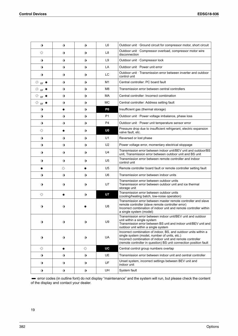
Control Devices EDSG18-936
19
error codes (in outline font) do not display “maintenance” and the system will run, but please check the content
of the display and contact your dealer.
L6 Outdoor unit · Ground circuit for compressor motor, short circuit
L8Outdoor unit · Compressor overload, compressor motor wire disconnection
L9 Outdoor unit · Compressor lock
LA Outdoor unit · Power unit error
LCOutdoor unit · Transmission error between inverter and outdoor control unit
or M1 Central controller: PC board fault
or M8 Transmission error between central controllers
or MA Central controller: Incorrect combination
or MC Central controller: Address setting fault
P0 Insufficient gas (thermal storage)
P1 Outdoor unit · Power voltage imbalance, phase loss
P4 Outdoor unit · Power unit temperature sensor error
U0Pressure drop due to insufficient refrigerant, electric expansion valve fault, etc.
U1 Reversed or lost phase
U2 Power voltage error, momentary electrical stoppage
U4Transmission error between indoor unit/BEV unit and outdoor/BS unit, Transmission error between outdoor unit and BS unit
U5Transmission error between remote controller and indoor control unit
U5 Remote controller board fault or remote controller setting fault
U6 Transmission error between indoor units
U7Transmission error between outdoor unitsTransmission error between outdoor unit and ice thermal storage unit
U7Transmission error between outdoor units (cooling/heating batch, low-noise operation)
U8
Transmission error between master remote controller and slave remote controller (slave remote controller error)Incorrect combination of indoor unit and remote controller within a single system (model)
U9
Transmission error between indoor unit/BEV unit and outdoor unit within a single systemTransmission error between BS unit and indoor unit/BEV unit and outdoor unit within a single system
UA
Incorrect combination of indoor, BS, and outdoor units within a single system (model, number of units, etc.)Incorrect combination of indoor unit and remote controller (remote controller in question) BS unit connection position fault
UC Central control group numbers overlap
UE Transmission error between indoor unit and central controller
UFUnset system, incorrect settings between BEV unit and indoor unit
UH System fault
382 Options
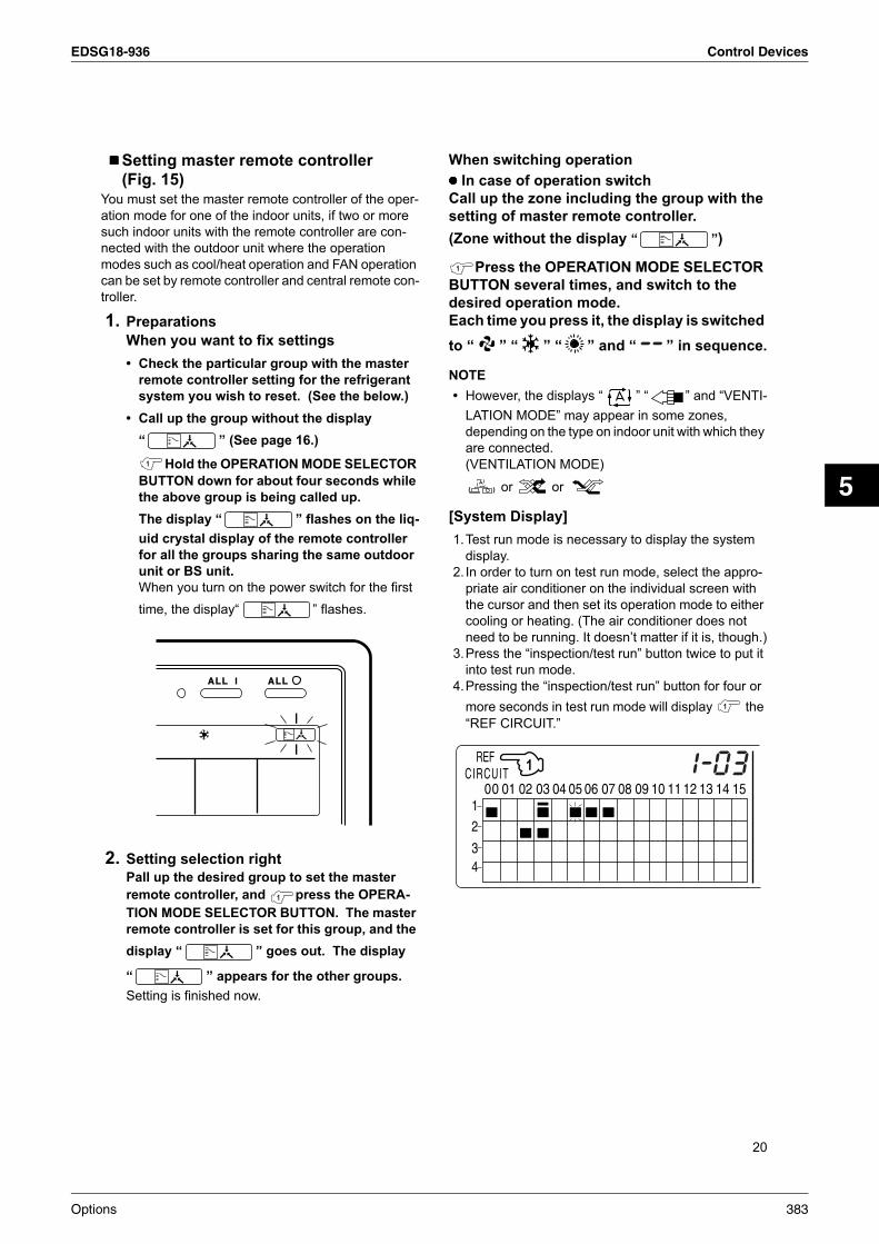
EDSG18-936 Control Devices
5
20
Setting master remote controller
(Fig. 15)You must set the master remote controller of the oper-
ation mode for one of the indoor units, if two or more
such indoor units with the remote controller are con-
nected with the outdoor unit where the operation
modes such as cool/heat operation and FAN operation
can be set by remote controller and central remote con-
troller.
1. Preparations
When you want to fix settings
• Check the particular group with the master
remote controller setting for the refrigerant
system you wish to reset. (See the below.)
• Call up the group without the display
“ ” (See page 16.)
Hold the OPERATION MODE SELECTOR
BUTTON down for about four seconds while
the above group is being called up.
The display “ ” flashes on the liq-
uid crystal display of the remote controller
for all the groups sharing the same outdoor
unit or BS unit.
When you turn on the power switch for the first
time, the display“ ” flashes.
2. Setting selection right
Pall up the desired group to set the master
remote controller, and press the OPERA-
TION MODE SELECTOR BUTTON. The master
remote controller is set for this group, and the
display “ ” goes out. The display
“ ” appears for the other groups.
Setting is finished now.
When switching operation
In case of operation switch
Call up the zone including the group with the
setting of master remote controller.
(Zone without the display “ ”)
Press the OPERATION MODE SELECTOR
BUTTON several times, and switch to the
desired operation mode.
Each time you press it, the display is switched
to “ ” “ ” “ ” and “ ” in sequence.
NOTE
• However, the displays “ ” “ ” and “VENTI-
LATION MODE” may appear in some zones,
depending on the type on indoor unit with which they
are connected.
(VENTILATION MODE)
or or
[System Display]
1.Test run mode is necessary to display the system
display.
2. In order to turn on test run mode, select the appro-
priate air conditioner on the individual screen with
the cursor and then set its operation mode to either
cooling or heating. (The air conditioner does not
need to be running. It doesn’t matter if it is, though.)
3.Press the “inspection/test run” button twice to put it
into test run mode.
4.Pressing the “inspection/test run” button for four or
more seconds in test run mode will display the
“REF CIRCUIT.”
Options 383

Control Devices EDSG18-936
21
Call the unit whose system you wish to look up using
the arrow keys.
The “ ” on all groups in the same system as the
displayed group will light up.
Of those, the “ ” display in all groups which have
cooling/heating selection privilege will blink.
In this example, individual units 1-00, 1-03, 1-05,
1-06, 1-07, 2-02, and 2-03 are in the same system,
and 1-05 has the cooling/heating selection privi-
lege.
To look up other systems, call up all the units you wish
to look up using the arrow keys.
Pressing the inspection/test run button one more time
gets rid of the system display and ends it.
The unit will enter the individual screen automatically if
nothing is done for one minute in the system display
screen.
This function may not be available for all connected
outdoor units, in which case “REF CIRCUIT” will blink.
It will also not be correctly displayed if DIII-NET exten-
sion ADP is used.
Display of time to clean (Fig. 16)This central remote controller displays the time to clean
the air filter or air cleaner element for each group or any
given group by utilizing two types of signs. The display
“ ” tells the time to clean the air filter or the air
cleaner element of some group.
If a cleaning sign is displayedA filter or element in some group is ready to be
cleaned.
1. Press the ARROW KEY BUTTON, and
search the groups displaying “ ” or
“ ” (The group may be plural.)
2. Press the FILTER SIGN RESET BUT-
TON, and the display “ ” disap-
pears. (Including all the groups where the
air filter has been cleaned.)
NOTE
Be sure to check the display “ ” has
disappeared at this point. The appearance of the
above display is a sign that the air filter or air cleaner
element of some group still needs cleaning.
Clean or change the air filter or air cleaner
element.
For further details, see the operation manual
attached to each indoor unit. (Clean or change the
air filter or air cleaner element of all the groups dis-
playing “ ” or “ ”.)
384 Options
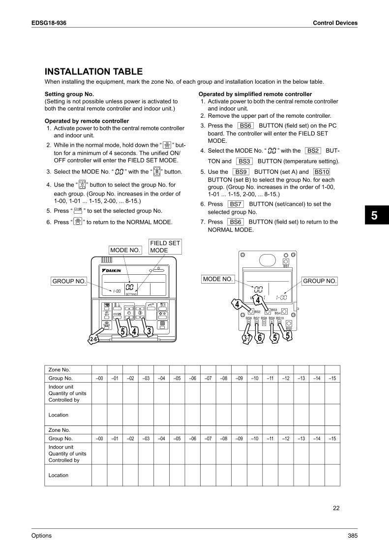
EDSG18-936 Control Devices
5
22
INSTALLATION TABLEWhen installing the equipment, mark the zone No. of each group and installation location in the below table.
Setting group No.
(Setting is not possible unless power is activated to
both the central remote controller and indoor unit.)
Operated by remote controller
1. Activate power to both the central remote controller
and indoor unit.
2. While in the normal mode, hold down the “ ” but-
ton for a minimum of 4 seconds. The unified ON/
OFF controller will enter the FIELD SET MODE.
3. Select the MODE No. “ ” with the “ ” button.
4. Use the “ ” button to select the group No. for
each group. (Group No. increases in the order of
1-00, 1-01 ... 1-15, 2-00, ... 8-15.)
5. Press “ ” to set the selected group No.
6. Press “ ” to return to the NORMAL MODE.
Operated by simplified remote controller
1. Activate power to both the central remote controller
and indoor unit.
2. Remove the upper part of the remote controller.
3. Press the BUTTON (field set) on the PC
board. The controller will enter the FIELD SET
MODE.
4. Select the MODE No. “ ” with the BUT-
TON and BUTTON (temperature setting).
5. Use the BUTTON (set A) and
BUTTON (set B) to select the group No. for each
group. (Group No. increases in the order of 1-00,
1-01 ... 1-15, 2-00, ... 8-15.)
6. Press BUTTON (set/cancel) to set the
selected group No.
7. Press BUTTON (field set) to return to the
NORMAL MODE.
Zone No.
Group No. –00 –01 –02 –03 –04 –05 –06 –07 –08 –09 –10 –11 –12 –13 –14 –15
Indoor unit
Quantity of units
Controlled by
Location
Zone No.
Group No. –00 –01 –02 –03 –04 –05 –06 –07 –08 –09 –10 –11 –12 –13 –14 –15
Indoor unit
Quantity of units
Controlled by
Location
Options 385
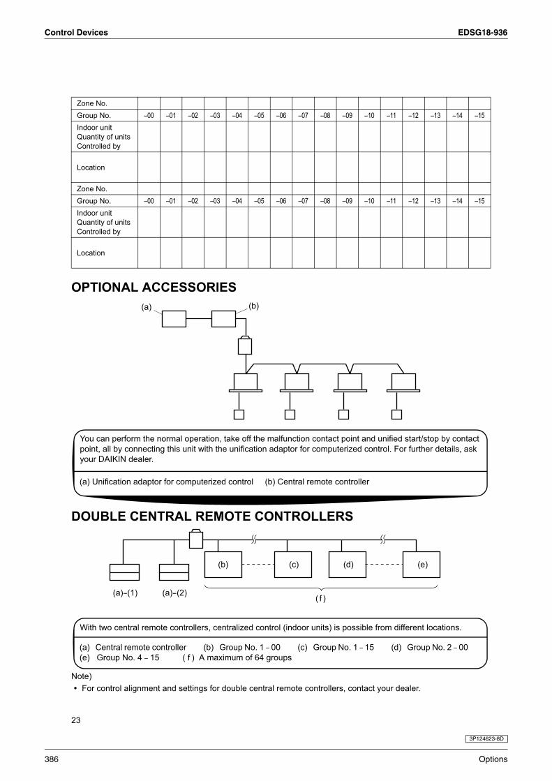
Control Devices EDSG18-936
23
OPTIONAL ACCESSORIES
DOUBLE CENTRAL REMOTE CONTROLLERS
Note)
• For control alignment and settings for double central remote controllers, contact your dealer.
Zone No.
Group No. –00 –01 –02 –03 –04 –05 –06 –07 –08 –09 –10 –11 –12 –13 –14 –15
Indoor unit
Quantity of units
Controlled by
Location
Zone No.
Group No. –00 –01 –02 –03 –04 –05 –06 –07 –08 –09 –10 –11 –12 –13 –14 –15
Indoor unit
Quantity of units
Controlled by
Location
You can perform the normal operation, take off the malfunction contact point and unified start/stop by contact
point, all by connecting this unit with the unification adaptor for computerized control. For further details, ask
your DAIKIN dealer.
(a) Unification adaptor for computerized control (b) Central remote controller
With two central remote controllers, centralized control (indoor units) is possible from different locations.
(a) Central remote controller (b) Group No. 1 – 00 (c) Group No. 1 – 15 (d) Group No. 2 – 00
(e) Group No. 4 – 15 ( f ) A maximum of 64 groups
3P124623-8D
386 Options

EDSG18-936 Control Devices
5
4.2 <DCS301BA61> Unified ON/OFF ControllerTurns up to 16 groups of indoor units (max. 128 units) on/off (operation/stop) by individual group or all at once, and lets you check display of operation/malfunction at the same time.
4.2.1 Dimensions
Unified ON/OFF Controller
For a maximum of 16 groups of indoor units (max. 128 units), unified operation/stop or individual operation/stop can be performed with this optional accessory. Also allows you check operation/error display at a glance.By combining with a central remote controller and schedule timer, you can construct a system that matches the size and use of the building.Up to 8 units connectable within 1 system.Up to 16 units in the double central control mode.Features thin design of a mere 16mm in thickness. (Uses JIS recessed box for 2.)Wiring can be up to 1km in length. Applicable wiring methods include bus and star in addition to crossover type.Can be used in combination with other D-BACS equipment.
120 16
90
71.0
46
120
52.5
83.5
T2
04
12
02
DCS301B51 • 61
05
D2ON/OFF CONTROLLER
07
F2 F1
ALL I
03
Optional switch box
00
13 15
11
01
06
UNIFIED
14
HOST
09
D1
ALL
10
2-5 x 7 round end slit
08
T1
3D050339
Options 387

Control Devices EDSG18-936
4.2.2 Installation Manual
GNINRAW
rroc ti llatsni ot erus eb dna tnempiuqe gninoitidnoc ria gnillatsni erofeb ylluferac ”SNOITAREDISNOC YTEFAS“ eseht daer esaelP eht gnitelpmoc retfA .yltceo ot woh no remotsuc eht tcurtsni esaelP .noitarepo pu-trats eht gnirud ylreporp setarepo tinu eht taht erus ekam ,noitallatsni .deniatniam ti peek dna tinu eht etarep
.ecnerefer erutuf rof launam noitarepo eht htiw gnola launam noitallatsni siht erots dluohs yeht taht sremotsuc mrofni ,oslA .”cilbup lareneg eht ot elbissecca ton secnailppa“ mret eht rednu semoc renoitidnoc ria sihT
GNINRAW ...... .yrujni suoires ro htaed ni tluser dluoc ,dediova ton fi ,hcihw noitautis suodrazah yllaitnetop a noitacidnINOITUAC ....... esu eb osla yam tI .yrujni etaredom ro ronim ni tluser yam ,dediova ton fi ,hcihw noitautis suodrazah yllaitnetop a noitacidnI .secitcarp efasnu tsniaga trela ot d
ETON ............. .stnedicca ylno-egamad-ytreporp ro tnempiuqe ni tluser yam taht noitautis noitacidnI
.flesruoy yb enihcam eht llatsni ot yrt ton oD .krow noitallatsni tuo yrrac ot lennosrep deifilauq ro relaed ruoy ksA.erif ro skcohs cirtcele ,egakael retaw ni tluser yam noitallatsni reporpmI
.launam noitallatsni siht htiw ecnadrocca ni krow noitallatsni mrofreP.erif ro skcohs cirtcele ,egakael retaw ni tluser yam noitallatsni reporpmI
.krow noitallatsni rof strap dna seirossecca deificeps eht ylno esu ot erus eB.gnillaf tinu eht ro erif ,skcohs cirtcele ,egakael retaw ni tluser yam strap deificeps eht esu ot eruliaF
.sekauqhtrae ro snoohpyt ,sdniw gnorts tnuocca otni gnikat retfa krow noitallatsni deificeps eht tuo yrraC.stnedicca gnisuac dna gnillaf tnempiuqe eht ni tluser yam krow noitallatsni reporpmI
ifilauq yb tuo deirrac si krow lacirtcele lla taht dna tinu siht rof dedivorp si tiucric ylppus rewop etarapes a taht erus ekaM lacol ot gnidrocca lennosrep de.launam noitallatsni siht dna snoitaluger dna swal
.erif ro skcohs cirtcele ot dael yam noitcurtsnoc lacirtcele reporpmi ro yticapac ylppus rewop tneiciffusni nA
w ro snoitcennoc lanimret eht no tca secrof lanretxe on dna ,desu dna seriw deificeps eht ,deruces si gniriw lla taht erus ekaM .seri.erif ni tluser yam noitallatsni ro snoitcennoc reporpmI
ht taht os seriw eht noitisop ,gniriw noissimsnart dna gniriw rellortnoc etomer eht gnitcennoc dna ylppus rewop eht gniriw nehW .denetsaf yleruces eb nac dil xob strap cirtcele e.gnitaehrevo slanimret eht ro erif ,skcohs cirtcele ni tluser yam dil xob strap cirtcele eht fo gninoitisop reporpmI
.tinu eht ffo nrut ,strap lacirtcele gnihcuot erofeB
.eriw dnuorg enohpelet a ro dor gninthgil ,sepip retaw ro sag ot eriw dnuorg eht tcennoc ton oD .renoitidnoc ria eht dnuorG.skcohs cirtcele ni tluser yam gnidnuorg etelpmocnI
deificeps eht naht rehto secnatsbus morf eerf tiucric tnaregirfer eht peek ot erus eb ,metsys eht gnitacoler ro gnillatsni nehW .ria sa hcus ,)A014R( tnaregirfer
.secived noitcetorp eht fo sgnittes eht egnahc ro tcurtsnocer ton oD esoht naht rehto strap ro ,ylbicrof detarepo dna detrohs si ecived noitcetorp rehto ro ,hctiws lamreht ,hctiws erusserp eht fI ro erif ,desu era nikiaD yb deificeps
.tluser yam noisolpxe
.sregnif tew htiw hctiws eht hcuot ton oD .kcohs cirtcele esuac nac sregnif tew htiw hctiws a gnihcuoT
.deriuqer sa ,rekaerb tiucric kael na llatsnI .tluser yam kcohs cirtcele ,dellatsni ton si rekaerb tiucric kael na fI
:snoitacol gniwollof eht ni rellortnoc etomer eht ro renoitidnoc ria eht llatsni ton oD nehctik a ni elpmaxe rof ,decudorp si ropav ro yarps lio na ro tsim lio larenim a erehw )a(
.egakael retaw ni tluser ro ffo llaf dna etaroireted yam strap citsalP decudorp si ,sag dica suoruflus sa hcus ,sag evisorroc erehw )b(
.egakael tnaregirfer ni tluser yam strap deredlos ro sepip reppoc gnidorroC sevaw citengamortcele gnittime yrenihcam raen )c(
.tnempiuqe eht fo noitcnuflam a ni tluser dna metsys lortnoc eht fo noitarepo eht brutsid yam sevaw citengamortcelEf elitalov erehw ro ,ria eht ni snoisnepsus tsud elbatingi ro rebif nobrac era ereht erehw ,kael yam sesag elbammalf erehw )d( ro renniht sa hcus selbammal
.deldnah era enilosag.erif ni tluser yam snoitidnoc hcus ni tinu eht gnitarepO
NOITUAC.noitatropsnart tcudorp tuoba luferac yrev eB
.slairetam gnikcap eht fo esopsid ylefaS .seirujni rehto ro sbats esuac yam ,strap nedoow ro latem rehto dna slian sa hcus ,slairetam gnikcaP gab citsalp a htiw yalp nerdlihc fI .meht htiw yalp ton lliw nerdlihc taht os sgab gnigakcap citsalp yawa worht dna trapa raeT .noitacoffus fo ksir eht ecaf yeht ,trapa nrot ton saw hcihw
.noitarepo gnippots retfa yletaidemmi rewop eht ffo nrut ton oD .rucco yam elbuort dna egakael retaw ,esiwrehtO .rewop eht ffo gninrut erofeb setunim evif tsael ta tiaw syawlA
.slobmys eton dna noituac ,gninraw fo gninaeM
ETON
GNINRAW
soidar ro snoisivelet morf yawa .tf5.3 tsael ta seriw gnitcennoc dna gniriw ylppus rewop ,stinu roodtuo dna roodni eht llatsnI .esion ro ecnerefretni egami tneverp ot redro ni).esion eht etanimile ot hguone tneiciffus eb ton yam .tf5.3 fo ecnatsid a ,sevaw oidar eht no gnidnepeD(
al tnecseroulf cinortcele htiw smoor ni detcepxe naht retrohs tluser nac ecnatsid gnittimsnart )tik sseleriw( rellortnoc etomeR )sepyt trats dipar ro retrevni( .spm.elbissop sa spmal tnecseroulf morf yawa raf sa tinu roodni eht llatsnI
eler eht htiw ecnadrocca ni enod eb dluohs ,strap rehto lautneve dna lio ,tnaregirfer eht fo tnemtaert ,tinu eht fo gniltnamsiD .snoitaluger lanoitan dna lacol tnav
388 Options
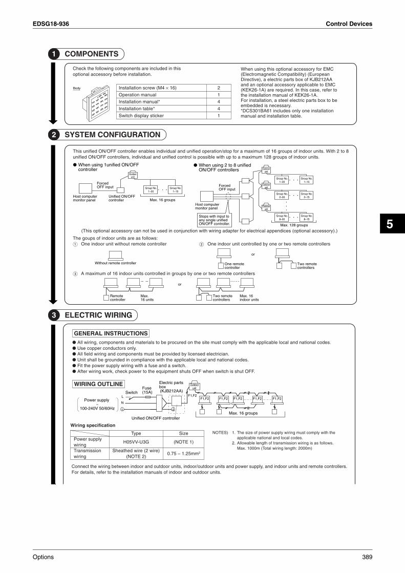
EDSG18-936 Control Devices
5
3 GNIRIW CIRTCELE
SNOITCURTSNI LARENEG.sedoc lanoitan dna lacol elbacilppa eht htiw ylpmoc tsum etis eht no derucorp eb ot slairetam dna stnenopmoc ,gniriw llA
.ylno srotcudnoc reppoc esU.naicirtcele desnecil yb dedivorp eb tsum stnenopmoc dna gniriw dleif llA
.sedoc lanoitan dna lacol elbacilppa eht htiw ecnailpmoc ni dednuorg eb llahs tinU.hctiws a dna esuf a htiw gniriw ylppus rewop eht tiF
.FFO tuhs si hctiws nehw FFO stuhs tnempiuqe eht ot rewop kcehc ,krow gniriw retfA
ENILTUO GNIRIW
lortnoc etomer dna stinu roodni dna ,ylppus rewop dna stinu roodtuo/roodni ,stinu roodtuo dna roodni neewteb gniriw eht tcennoC .srel.stinu roodtuo dna roodni fo slaunam noitallatsni eht ot refer ,sliated roF
spuorg 61 .xaM
ylppus rewoP~
zH06/05 V042-001
rellortnoc FFO/NO deifinU
strap cirtcelExob
)AA212BJK(esuF)A51(hctiwS
2F,1F2F,1F
2F,1F2F,1F2F,1F2F,1FL
N
roodtuOtinu
eht htiw ylpmoc tsum gniriw ylppus rewop fo ezis ehT.1)SETON.sedoc lacol dna lanoitan elbacilppa
.swollof sa si gniriw noissimsnart fo htgnel elbawollA.2)m0002 :htgnel gniriw latoT( m0001 .xaM
noitacificeps gniriW
epyT
G3U-VV50H
)eriw 2( eriw dehtaehS)2 ETON(
eziS
)1 ETON(
57.0 – mm52.1 2
ylppus rewoPgniriw
noissimsnarTgniriw
1 STNENOPMOC
siht ni dedulcni era stnenopmoc gniwollof eht kcehC.noitallatsni erofeb yrossecca lanoitpo
CME rof yrossecca lanoitpo siht gnisu nehWnaeporuE( )ytilibitapmoC citengamortcelE(AA212BJK fo xob strap cirtcele a ,)evitceriD
CME ot elbacilppa yrossecca lanoitpo na dnaot refer ,esac siht nI .deriuqer era )A1-62KEK(
.A1-62KEK fo launam noitallatsni ehteb ot xob strap cirtcele leets a ,noitallatsni roF
.yrassecen si deddebmenoitallatsni eno ylno sedulcni 16AB103SCD*
.elbat noitallatsni dna launam
2 NOITARUGIFNOC METSYS
:swollof sa era stinu roodni fo spuog ehTrellortnoc etomer tuohtiw tinu roodni enO
2 htiW .stinu roodni fo spuorg 61 fo mumixam a rof pots/noitarepo deifinu dna laudividni selbane rellortnoc FFO/NO deifinu sihT 8 ot .stinu roodni fo spuorg 821 mumixam a ot pu htiw elbissop si lortnoc deifinu dna laudividni ,srellortnoc FFO/NO deifinu
).)yrossecca lanoitpo( secidneppa lacirtcele rof retpada gniriw htiw noitcnujnoc ni desu eb ton nac yrossecca lanoitpo sihT(
srellortnoc etomer owt ro eno yb dellortnoc tinu roodni enO
srellortnoc etomer owt ro eno yb spuorg ni dellortnoc stinu roodni 61 fo mumixam A
ydoB
FFO/NO deifinu1 gnisu nehWrellortnoc
deifinu 8 ot 2 gnisu nehWsrellortnoc FFO/NO
retupmoc tsoHlenap rotinom
retupmoc tsoHlenap rotinom
FFO/NO deifinUrellortnoc
decroFtupni FFO decroF
tupni FFO
spuorg 821 .xaM
.oN puorG1– 00
.oN puorG1– 51
.oN puorG1– 00
.oN puorG1– 51
.oN puorG2– 00
.oN puorG2– 51
.oN puorG8– 00
.oN puorG8– 51
ot tupni htiw spotS deifinu elgnis yna.rellortnoc FFO/NO
roodtuOtinu
roodtuOtinu
roodtuOtinu
roodtuOtinu
spuorg 61 .xaM
rellortnoc etomer tuohtiW etomer enOrellortnoc
etomer owTsrellortnoc
ro
etomeRrellortnoc
.xaMstinu 61
61 .xaMstinu roodni
etomer owTsrellortnoc
ro
4M( wercs noitallatsnI × 2)61
1launam noitarepO
4*launam noitallatsnI
4*elbat noitallatsnI
1rekcits yalpsid hctiwS
Options 389

Control Devices EDSG18-936
NOISSIMSNART ROF GNIRIW FO SELPMAXE
gniriw seireS
.gnihcnarb retfa dewolla si gnihcnarb oN.1)SETONlanimret emas eht morf sgniriw lortnoc 3 naht erom hcnarb ot )dleif eht ni derucorp eb ot trap( draob lanimret yaler a esU.2
.draob
TINU ROODTUO DNA TINU ROODNI EHT OT GNIRIW
4 NOITALLATSNI
.rellortnoc etomer fo trap reppu eht nepOreppu eht neewteb ssecer eht otni )snoitacol 2( revirdwercs – a tresnI.ylthgil revirdwercs eht tsiwt dna rellortnoc etomer fo trap rewol eht dna trap
etomer fo trap rewol dna reppu eht htob htiw dehcatta si draob CP.revirdwercs eht htiw draob eht egamad ton oD .rellortnoc
strap cirtcele eht llatsni dna rellortnoc etomer fo trap reppu eht nepOswercs noitallatsni dehcatta eht htiw )dleif eht ni derucorp eb ot trap( xob
4M( × .)61
fo telni eht morf mm061 tuoba si eriw cirtcele eht fo htgnel elbatiuS)ETONeht pirts ,gniriw gnol a niatnoc ot tluciffid si ti fI .xob strap cirtcele eht
.gniriw eht fo trap dehtaehs
)sgnihcnarb 61 ot pu dehcnarb eb naC( gniriw epyt ratS
sgnihcnarb 3 fo elpmaxE
)sgnihcnarb 61 ot pu dehcnarb eb naC( gniriw epyt suB
sgnihcnarb 3 fo elpmaxE
)ETON(b ro egamad yam ti ,ekatsim yb detcennoc fI .pirts lanimret lortnoc eht ot )V042 ot 022( gniriw ylppus rewop eht tcennoc ton oD fo strap lacirtcele nru
erofeb sgniriw kcehc ot erus eB .regnad suoires ni tluser yam tI .tinu roodni dna lortnoc dezilartnec rof srellortnoc lanoitpo .NO rewop eht gninrut
2F,1F2F,1F
2F,1FNO
FFO
)1 ETON(
2F,1F
2F,1F2F,1F
2F,1FNO
FFO
2F,1F2F,1F
2F,1F2F,1F
)1 ETON(
2F,1F
2F,1F2F,1F
2F,1F2F,1F
2F,1F
2F,1F2F,1F
NO
FFO
NO
FFOtinu roodtuO :tinu roodnI::
draob lanimreTderucorp eb ot traP(
)dleif eht ni:
FFO/NO deifinUrellortnoc
2F 1F 2F 1F 2F 1F 2F 1F
2F 1F2P 1P 2F 1F2P 1P 2F 1F2P 1P
2F 1F2P 1P2F 1F2P 1P
2F1FN L
N L N L
TINU D/NI OT TINU D/TUO OTtinu roodtuO
TINU D/NI OT TINU D/TUO OTtinu roodtuO
tinu roodnItinu roodnItinu roodnI
tinu roodnI
TINU ROODTUO OTtinu roodnI
)1 ETON( ylppus rewoP~
zH06/05 V042-001
)2F ,1F( tinu roodni gnitcennoc roF1 )2T ,1T( tupni FFO decroF2
)tnerruc orcim rof ,rotcatnoc egatlov on( tupni FFO decrof eht elihWdna deppots era stinu roodni detcennoc eht lla ,)dezigrene( NO si
.detarepo eb ton nac daol elbacilppa muminim eht eetnaraug hcihw srotcatnoc ylno esU
.Am01 ,V61CD
)2D ,1D( remit eludehcs roF3 15AB103TSD( remit eludehcs eht ot deilppus eb nac rewoP • 16
fo launam noitallatsni eht ot refer ,sliated roF .)yrossecca lanoitpo.remit eludehcs eht
.yrassecen nehw ylno 3 dna 2 eriW
fo rotcatnoc suoenatnatsni esU)ETON,emit gnizigrene .cesm002 revo
.yrassecen nehw
PIRTS LANIMRET LORTNOC
V61CD
1T
2T
2F1FN L
N L N L
cirtcelE xob strap
)AA212BJK(
yrossecca lanoitpO IME ot elbacilppa
)A1-62KEK(
yrossecca lanoitpo eht gnisu ton nehW .1 )ETON tcennoc ,)A1-62KEK( IME ot elbacilppa
eht ot yltcerid gniriw ylppus rewop eht.rellortnoc FFO/NO deifinu
1
2D1D2T1T2F1F
2 3
rof gniriWnoissimsnart
ylppus rewop eht niatnoc ton oD eht ni gniriw noissimsnart eht dna
.ebut tiudnoc emas
– revirdwercs
)snoitacol 2(
swercs noitallatsnI)swercs 2(
derucorp eb ot traP()dleif eht ni
strap cirtcelExob
ylppus rewoPgniriwebut tiudnoC
mm061 tuobA
xob strap cirtcelE
390 Options
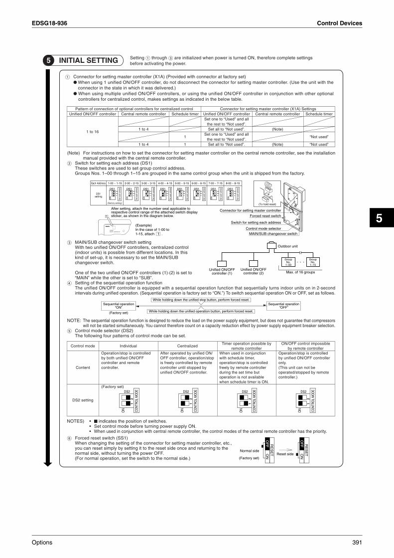
EDSG18-936 Control Devices
5
tsni eht ees ,rellortnoc etomer lartnec eht no rellortnoc retsam gnittes rof rotcennoc eht tes ot woh no snoitcurtsni roF)etoN( noitalla.rellortnoc etomer lartnec eht htiw dedivorp launam
)1SD( sserdda hcae gnittes rof hctiwS.sserdda lortnoc puorg tes ot desu era sehctiws esehT
1 .soN spuorG – 1 hguorht 00 – .yrotcaf eht morf deppihs si tinu eht nehw puorg lortnoc emas eht ni depuorg era 51
gnittes hctiws revoegnahc BUS/NIAMlortnoc dezilartnec ,srellortnoc FFO/NO deifinu owt htiW
siht nI .snoitacol tnereffid morf elbissop si )stinu roodni(BUS/NIAM eht tes ot yrassecen si ti ,pu-tes fo dnik
.hctiws revoegnahc
)1( srellortnoc FFO/NO deifinu owt eht fo enO · ot tes si )2(“ NIAM ” ot tes si rehto eht elihw “ BUS ”.
noitcnuf noitarepo laitneuqes eht fo gnitteSces-2 ni no stinu roodni snrut yllaitneuqes taht noitcnuf noitarepo laitneuqes a htiw deppiuqe si rellortnoc FFO/NO deifinu ehT dno
ot tes yrotcaf si noitarepo laitneuqeS( .noitarepo deifinu gnirud slavretni “ .NO ” .swollof sa tes ,FFO ro NO noitarepo laitneuqes hctiws oT )
:ETON moc taht eetnaraug ton seod tub ,tnempiuqe ylppus rewop eht no daol eht ecuder ot dengised si noitcnuf noitarepo laitneuqes ehT srosserprekaerb tnempiuqe ylppus rewop yb tceffe noitcuder yticapac a no tnuoc erofereht tonnac uoY .ylsuoenatlumis detrats eb ton lliw .noitceles
)2SD( rotceles edom lortnoC.tes eb nac edom lortnoc fo snrettap ruof gniwollof ehT
sserdda hcae gnittes rof hctiwS
rotceles edom lortnoChctiws revoegnahc BUS/NIAM
DEIFINURELLORTNOC FFO/NO
Set e
ach
adre
ss
sserddA hcaE 51-8 ~ 00-851-7 ~ 00-751-6 ~ 00-651-5 ~ 00-551-4 ~ 00-451-3 ~ 00-351-2 ~ 00-251-1 ~ 00-1
)gnittes yrotcaF(
1SDgnittes 1
ON
23
1SD
Set e
ach
adre
ss
1
ON
23
1SD
Set e
ach
adre
ss
1
ON
23
1SD
Set e
ach
adre
ss
1
ON
23
1SDSe
t eac
h ad
ress
1
ON
23
1SD
Set e
ach
adre
ss
1
ON
23
1SD
Set e
ach
adre
ss
1
ON
23
1SD
Set e
ach
adre
ss
1
ON
23
1SD
)teser dloh oT(
ot elbacilppa laes rebmun eht hcatta ,gnittes retfA yalpsid hctiws dehcatta eht fo egnar lortnoc evitcepser
.woleb margaid eht ni nwohs sa ,rekcits
rellortnoc retsam gnittes rof rotcennoC
hctiws teser decroF
)elpmaxE( ot 00-1 fo esac eht nI
. 1 hcatta ,51-1
1
FFO/NO deifinU)1( rellortnoc
puorG.oN
1– 00
puorG.oN
1– 51
spuorg 61 fo .xaM FFO/NO deifinU
)2( rellortnoc
tinu roodtuO
noitarepo laitneuqeS“ NO ”
)tes yrotcaF(
noitarepo laitneuqeS“ FFO ”
.teser decrof mrofrep ,nottub pots deifinu eht nwod gnidloh elihW
.teser decrof mrofrep ,nottub noitarepo deifinu eht nwod gnidloh elihW
RE
SE
TON
OF
FO
FF RE
SE
TON
OF
FO
FF
edis lamroN
)tes yrotcaF(edis teseR
)SETON • .sehctiws fo noitisop eht setacidni • .NO ylppus rewop gninrut erofeb edom lortnoc teS• .ytiroirp eht sah rellortnoc etomer lartnec eht fo sedom lortnoc eht ,rellortnoc etomer lartnec htiw noitcnujnoc ni desu nehW
)1SS( hctiws teser decroF,.cte ,rellortnoc retsam gnittes rof rotcennoc eht fo gnittes eht gnignahc nehW
eht ot gninruter dna ecno edis teser eht ot ti gnittes yb ylpmis teser nac uoy.FFO rewop eht gninrut tuohtiw ,edis lamron
).edis lamron eht ot hctiws eht tes ,noitarepo lamron roF(
elbissopmi lortnoc FFO/NOrellortnoc etomer yb
dellortnoc si pots/noitarepOrellortnoc FFO/NO deifinu yb
.ylnoeb ton nac tinu sihT(
etomer yb deppots/detarepo).rellortnoc
yb elbissop noitarepo remiTrellortnoc etomer
noitcnujnoc ni desu nehW,remit eludehcs htiw
dellortnoc si pots/noitareporellortnoc etomer yb yleerf
tub emit tes eht gnirudelbaliava ton si noitarepo
.NO si remit eludehcs nehw
dezilartneC
/NO deifinu yb detarepo retfApots/noitarepo ,rellortnoc FFO
etomer yb dellortnoc yleerf siyb deppots litnu rellortnoc.rellortnoc FFO/NO deifinu
laudividnI
dellortnoc si pots/noitarepOFFO/NO deifinu htob yb
etomer dna rellortnoc.rellortnoc
)tes yrotcaF(
edom lortnoC
tnetnoC
gnittes 2SD
12
CONT
ROL
MO
DE2SD
ON
12
CONT
ROL
MO
DE2SD
ON
12
CONT
ROL
MO
DE2SD
ON
12
CONT
ROL
MO
DE2SD
ON
sgnitteS )A1X( rellortnoc retsam gnittes rof rotcennoClortnoc dezilartnec rof srellortnoc lanoitpo fo noitcennoc fo nrettaPrellortnoc FFO/NO deifinU
61 ot 1
rellortnoc etomer lartneC
4 ot 1
4 ot 1
remit eludehcS
1
1
rellortnoc FFO/NO deifinU ot eno teS “ desU ” lla dna
ot tser eht “ desu toN ”. ot lla teS “ desu toN ”.
ot eno teS “ desU ” lla dna ot tser eht “ desu toN ”.
ot lla teS “ desu toN ”.
rellortnoc etomer lartneC
)etoN(
)etoN(
remit eludehcS
“ desu toN ”
“ desu toN ”
gnitteS hguorht sgnittes etelpmoc erofereht ,NO denrut si rewop nehw dezilaitini era .rewop eht gnitavitca erofeb5 GNITTES LAITINI
)tes yrotcaf ta rotcennoc htiw dedivorP( )A1X( rellortnoc retsam gnittes rof rotcennoCeht htiw tinu eht esU( .rellortnoc retsam gnittes rof rotcennoc eht tcennocsid ton od ,rellortnoc FFO/NO deifinu 1 gnisu nehW
).dereviled saw ti hcihw ni etats eht ni rotcennoclanoitpo rehto htiw noitcnujnoc ni rellortnoc FFO/NO deifinu eht gnisu ro ,srellortnoc FFO/NO deifinu elpitlum gnisu nehW
.elbat woleb eht ni detacidni sa sgnittes sekam ,lortnoc dezilartnec rof srellortnoc
Options 391

Control Devices EDSG18-936
NO eht sserp dna rellortnoc FFO/NO deifinu dna ,stinu roodtuo ,stinu roodni eht ot rewop ylppus ,noitarepo tset gnitrats erofeB .nottub FFO/.puorg elbacilppa eht fo tinu roodni eht ni noitcnuflam a setacidni ti ,sehsalf pmal noitarepo eht fI
fo yalpsid eht fI “ TSOH ” .snoitcnuflam hcus rof kcehC .lortnoc dezilartnec rof srellortnoc lanoitpo eht ni noitcnuflam a setacidni ti ,sehsalf
SETON • .tinu roodtuo eht htiw dehcatta launam noitallatsni eht ot refer ,stinu roodtuo dna roodni fo noitarepo tset roF• fo yalpsid eht htiw erom ro setunim owt rof noitarepo tpecca ton seod tinu eht fi ,NO ylppus rewop eht gninrut retfA
“ TSOH ” .stniop gniwollof eht kcehc ,gnihsalf
• .tcerroc si rellortnoc retsam gnittes rof rotcennoc eht fo gnittes taht kcehC • .tes neeb sah lortnoc dezilartnec rof .oN puorg eht taht kcehC
6 LORTNOC DEZILARTNEC ROF .ON PUORG GNITTES
7 NOITAREPO GNIMRIFNOC
cennoc osla ,rellortnoc etomer on fo esac nI( .rellortnoc etomer eht morf tinu roodni eht fo puorg hcae fo rebmun puorg eht teS eht t).rellortnoc etomer eht evomer ,nehT .oN puorg eht tes dna rellortnoc etomer
.RELLORTNOC FFO/NO DEIFINU dna tinu roodni eht fo rewop eht NO nruT)1().edam eb nac gnittes on ,NO si rewop eht sselnU(
.NO ylppus rewop eht gninrut erofeb tcerroc era gniriw lacirtcele dna noitallatsni eht taht kcehCht htiw etunim eno tuoba rof noitarepo eht tpecca ton yam tinu eht dna ecno raeppa DCL lla ,NO denrut si ylppus rewop eht nehW( e
).” “ fo yalpsid
.elbat noitallatsni eht ees ,rellortnoc etomer deifilpmis roF)SETON rieht no sliated rof )sretpada esoprup-itlum ,.e.i( sretpada dna riaitneV eht htiw emac hcihw slaunam noitcurtsni eht eeS
.sgnittes .oN puorG
ECITON .launam noitarepo eht ni elbat noitallatsni eht otni tinu roodni eht fo ecalp noitallatsni dna .oN puorg eht retnE.ecnanetniam rof launam noitarepo eht peek ot erus eB
a rof nottub ” “ eht nwod dloh ,edom lamron eht ni elihW)2(.sdnoces 4 fo muminim
.EDOM TES DLEIF eht retne lliw rellortnoc etomer ehT
.nottub ” “ eht htiw ” “ .oN EDOM eht tceleS )3(
.puorg hcae rof .oN puorg eht tceles ot nottub ” “ eht esU )4(
,10-1,00-1 fo redro eht ni esaercni srebmun puorG( ... ,00-2 ,51-1... ).51-8
.oN puorg detceles eht tes ot ” “ sserP)5(
.EDOM LAMRON eht ot nruter ot ” “ sserP )6(
.ON PUORG
.ON EDOM
TES DLEIFEDOM
TSET
GNITTES
342.6
5
TSET
TSET
1P162827-1
392 Options

EDSG18-936 Control Devices
5
4.2.3 Operation Manual
Please read these “SAFETY CONSIDERATIONS” carefully before installing air conditioning equipment and be sure to install it correctly. After completing the installation, make sure that the unit operates properly during the start-up operation.Please instruct the customer on how to operate the unit and keep it maintained.Also, inform customers that they should store this installation manual along with the operation manual for future reference.This air conditioner comes under the term “appliances not accessible to the general public”.
WARNING ......Indicates a potentially hazardous situation which, if not avoided, could result in death or serious injury. CAUTION .......Indicates a potentially hazardous situation which, if not avoided, may result in minor or moderate injury. It may also be used to alert against unsafe practices.NOTE .............Indicates situation that may result in equipment or property-damage-only accidents.
WARNING
In order to avoid electric shock, fire or injury, or if you detect any abnormality such as smell of fire, turn off power and call your dealer for instructions.
Ask your dealer for installation of the air conditioner.Incomplete installation performed by yourself may result in a water leakage, electric shock, and fire.Ask your dealer for improvement, repair, and maintenance.Incomplete improvement, repair, and maintenance may result in a water leakage, electric shock, and fire.
Improper installation or attachment of equipment or accessories could result in electric shock, short-circuit, leaks, fire or other damage to the equipment. Be sure only to use accessories made by Daikin which are specifically designed for use with the equipment and have them installed by a professional.
Ask your dealer to move and reinstall the air conditioner or the remote controller. Incomplete installation may result in a water leakage, electric shock, and fire.
Never let the indoor unit or the remote controller get wet.It may cause an electric shock or a fire.
Never use flammable spray such as hair spray, lacquer or paint near the unit.It may cause a fire.
Never replace a fuse with that of wrong ampere ratings or other wires when a fuse blows out.Use of wire or copper wire may cause the unit to break down or cause a fire.
Never inspect or service the unit by yourself.Ask a qualified service person to perform this work.
Cut off all electric waves before maintenance.
Do not wash the air conditioner or the remote controller with excessive water.Electric shock or fire may result.
Do not install the air conditioner or the remote controller at any place where flammable gas may leak out.If the gas leaks out and stays around the air conditioner, a fire may break out.
Do not touch the switch with wet fingers.Touching a switch with wet fingers can cause electric shock.
CAUTIONAfter a long use, check the unit stand and fitting for damage.If they are left in a damaged condition, the unit may fall and result in injury.
Do not allow a child to mount on the unit or avoid placing any object on it.Falling or tumbling may result in injury.
NOTENever press the button of the remote controller with a hard, pointed object.The remote controller may be damaged.
Never pull or twist the electric wire of the remote controller.It may cause the unit to malfunction.
Do not place the controller exposed to direct sunlight.The LCD display may get discolored, failing to display the data.
Dismantling of the unit, treatment of the refrigerant, oil and eventual other parts, should be done in accordance with the relevant local and national regulations.
Do not wipe the controller operation panel with benzine, thinner, chemical dustcloth, etc.The panel may get discolored or the coating peeled off. If it is heavily dirty, soak a cloth in water-diluted neutral detergent, squeeze it well and wipe the panel clean. And wipe it with another dry cloth.
Meaning of warning, caution and note symbols.
Keep these warning sheets handy so that you can refer to them if needed.Also, if this equipment is transferred to a new user, make sure to hand over this operation manual to the new user.
Do not let children play on and around the unit.If they touch the unit carelessly, it may result in injury.
Do not place a flower vase and anything containing water.Water may enter the unit, causing an electric shock or fire.
Avoid placing the controller in a spot splashed with water.Water coming inside the machine may cause an electric leak or may damage the internal electronic parts.
Do not operate the air conditioner when using a room fumigation - type insecticide.Failure to observe could cause the chemicals to become deposited in the unit, which could endanger the health of those who are hypersensitive to chemicals.
Do not turn off the power immediately after stopping operation.Always wait at least five minutes before turning off the power. Otherwise, water leakage and trouble may occur.
The appliance is not intended for use by young children or infirm persons without supervision.
Safely dispose of the packing materials.Packing materials, such as nails and other metal or wooden parts, may cause stabs or other injuries.Tear apart and throw away plastic packaging bags so that children will not play with them. If children play with a plastic bag which was not torn apart, they face the risk of suffocation.
Never touch the internal parts of the controller.Do not remove the front panel. Some parts inside are dangerous to touch, and a machine trouble may happen. For checking and adjusting the internal parts, contact your dealer.
The remote controller should be installed in such away that children cannot play with it.
Options 393

Control Devices EDSG18-936
<<<< >>>>NOTE When using unified ON/OFF controller with other optional controllers f•
•
or centralized control, “OPERATION LAMP” of the equipment which is not operated may turn on or off after several minutes.This state occurs due to signal communications and is not a failure.Do not open the upper part of remote controller except when rewriting the indication sticker or selecting control modes.
NAMES AND FUNCTIONS1
PUTTING ROOM NAME INDICATION STICKER2
ON/OFF CONTRON/OFF CONTROLLEROLLERUNIFIEDUNIFIED
HOST ALL ALL
00 030201
04 070605
08 111009
12 151413
OPERATION LAMP
Turns on during operation ofeach group and flashesduring malfunction stop.
GROUP NO.
ROOM NAME INDICATIONPLATE
Refer to the “2. PUTTINGROOM NAME INDICATIONSTICKER”
“UNDER HOST COMPUTERINTEGRATED CONTROL” LAMP
When this lamp turns on, no otheroperations are possible.
UNIFIED OPERATION/STOPBUTTON
Starts/stops all indoor units.
INDIVIDUAL OPERATION/STOP BUTTON
Starts/stops each indoorunit group individually.
Open the upper part of remote controller. Insert a (–) screwdriver into the recess between the upper and lower part of remote controller (at 2 locations) and twist the screwdriver lightly.
Put the attached indication sticker on the room name indication plate.
Reinstall the plate as it were, with checking the correct direction. Close the upper part of remote controller.
Pull out the room name indication plate. Insert the point of a mechanical pencil etc, into the hole of the indication sticker to pull it out.
PC board is attached both the upper and lower part of remote controller.Do not damage the board with the screwdriver.
(–) screwdriver
(2 locations)
Indication plate
Control mode selector
(DS2)
Indication sticker
Indication sticker
In case of individual type
Put the sticker aligning the lines of the sticker with those of the plate.
Indication plate
Indication plate
In case of serial type
Put the sticker on the center of the frame.Write the room name in the frame of the sticker with a ball point pen or a felt-tip pen (oil-base).
SELECTING CONTROL MODES3
ON CO
NTRO
L M
ODE
12
ON
12
CONT
ROL
MO
DE
ON
12
CONT
ROL
MO
DE
The following four patterns of control mode can be set.
(Fa
cto
ry s
et)
Control mode
Content
DS2 setting
Individual CentralizedTimer operation possible by
remote controllerON/OFF control impossible by
remote controller
Operation/stop is controlled by both unified ON/OFF controller and remote controller.
After operated by unified ON/OFF controller, operation/stop is freely controlled by remote controller untilstopped by unified ON/OFFcontroller.
When used in conjunction with schedule timer, operation/stop is controlled freely by remote controller during the set time but operation is not available when schedule timer is ON.
Operation/stop is controlled by unified ON/OFF controller only. Indoor units can not be operated/ stopped by remote controller.
NOTE : • indicates the position of switches.• Set control modes before turning power supply on.• When used in conjunction with central remote controller, the control modes of the central remote controller has the priority.
ON
12
CONT
ROL
MO
DE
DISPLAY OF MALFUNCTION4
Flashing of lamps indicates malfunctions. Contact your Daikin dealer.When turning power supply on, all lamps may light and UNDER HOST COMPUTER INTEGRATED CONTROL lamp may flash and not accept the operation for about one minute.These conditions are not malfunctions.
States of lamps Contents of malfunctions
Flashing of operation lamp Indicates malfunctions in the indoor unit in the group where the operation lamp is flashing.
Flashing of UNDER HOST COMPUTER INTEGRATED CONTROL lamp Indicates malfunctions in optional controllers for centralized control.
2P167410-1
394 Options

EDSG18-936 Control Devices
5
4.3 <DST301BA61> Schedule TimerEnables you to connect and control weekly schedule for up to 128 indoor units all together.
4.3.1 Specifications / Dimensions
Simultaneous control of up to 128 indoor units is managed by a week schedule.The start and stop time for twice a day can be set for the week in increments of 1 minute.By combining with a central remote controller and schedule timer, you can construct a system that matches the size and use of the building.If used together with a central remote controller, you can set up to 8 schedule patterns which can be distributed among zones as desired using the central remote controller.Is equipped with a compensation function for power failure up to 48 hours.Features thin design of a mere 16 mm in thickness. (Uses JIS recessed box for 2.)Wiring can be up to 1 km in length. Applicable wiring methods include bus and star in addition to crossover type.Can be used in combination with other D-BACS equipment.
SPECIFICATIONSSpecifications
Outline drawings
Specifications and appearance subject to change without notice.
Display of time 12-hour digital display
Clock cycle type Quartz clock type
Clock accuracy Within ±30 sec./month (environmental temperature from 15˚C to 35˚C)
Timer programmingTwo pairs of programmed time for both system start and system off can be set in units of minute for each day of the week
Power failure compensation time Approximately 48 hours for a single occurrence of power failure (clock with No. of programmed time)
Size 120 (W) × 120 (H) × 53 (D) mm(Width/Height/Depth)
Weight Approximately 210g
120 16 37
71120
Options 395

Control Devices EDSG18-936
4.3.2 Installation Manual
GNINRAW
ot erus eb dna tnempiuqe gninoitidnoc ria gnillatsni erofeb ylluferac ”SNOITAREDISNOC YTEFAS“ eseht daer esaelPoitarepo pu-trats eht gnirud ylreporp setarepo tinu eht taht erus ekam ,noitallatsni eht gnitelpmoc retfA .yltcerroc ti llatsni .n
.deniatniam ti peek dna tinu eht etarepo ot woh no remotsuc eht tcurtsni esaelP.ecnerefer erutuf rof launam noitarepo eht htiw gnola launam noitallatsni siht erots dluohs yeht taht sremotsuc mrofni ,oslA
.”cilbup lareneg eht ot elbissecca ton secnailppa“ mret eht rednu semoc renoitidnoc ria sihT
GNINRAW .yrujni suoires ro htaed ni tluser dluoc ,dediova ton fi ,hcihw noitautis suodrazah yllaitnetop a noitacidnI...... NOITUAC yam tI .yrujni etaredom ro ronim ni tluser yam ,dediova ton fi ,hcihw noitautis suodrazah yllaitnetop a noitacidnI.......
.secitcarp efasnu tsniaga trela ot desu eb oslaETON .stnedicca ylno-egamad-ytreporp ro tnempiuqe ni tluser yam taht noitautis noitacidnI.............
GNINRAW.flesruoy yb enihcam eht llatsni ot yrt ton oD .krow noitallatsni tuo yrrac ot lennosrep deifilauq ro relaed ruoy ksA
.erif ro skcohs cirtcele ,egakael retaw ni tluser yam noitallatsni reporpmI
.launam noitallatsni siht htiw ecnadrocca ni krow noitallatsni mrofreP.erif ro skcohs cirtcele ,egakael retaw ni tluser yam noitallatsni reporpmI
.krow noitallatsni rof strap dna seirossecca deificeps eht ylno esu ot erus eB.gnillaf tinu eht ro erif ,skcohs cirtcele ,egakael retaw ni tluser yam strap deificeps eht esu ot eruliaF
.sekauqhtrae ro snoohpyt ,sdniw gnorts tnuocca otni gnikat retfa krow noitallatsni deificeps eht tuo yrraC.stnedicca gnisuac dna gnillaf tnempiuqe eht ni tluser yam krow noitallatsni reporpmI
yb tuo deirrac si krow lacirtcele lla taht dna tinu siht rof dedivorp si tiucric ylppus rewop etarapes a taht erus ekaM.launam noitallatsni siht dna snoitaluger dna swal lacol ot gnidrocca lennosrep deifilauq
.erif ro skcohs cirtcele ot dael yam noitcurtsnoc lacirtcele reporpmi ro yticapac ylppus rewop tneiciffusni nAw ro snoitcennoc lanimret eht no tca secrof lanretxe on dna ,desu dna seriw deificeps eht ,deruces si gniriw lla taht erus ekaM .seri
.erif ni tluser yam noitallatsni ro snoitcennoc reporpmI
seriw eht noitisop ,gniriw noissimsnart dna gniriw rellortnoc etomer eht gnitcennoc dna ylppus rewop eht gniriw nehW.denetsaf yleruces eb nac dil xob strap cirtcele eht taht os
.gnitaehrevo slanimret eht ro erif ,skcohs cirtcele ni tluser yam dil xob strap cirtcele eht fo gninoitisop reporpmI
.tinu eht ffo nrut ,strap lacirtcele gnihcuot erofeB
.eriw dnuorg enohpelet a ro dor gninthgil ,sepip retaw ro sag ot eriw dnuorg eht tcennoc ton oD .renoitidnoc ria eht dnuorG.skcohs cirtcele ni tluser yam gnidnuorg etelpmocnI
eht naht rehto secnatsbus morf eerf tiucric tnaregirfer eht peek ot erus eb ,metsys eht gnitacoler ro gnillatsni nehW .ria sa hcus ,)A014R( tnaregirfer deificeps
.secived noitcetorp eht fo sgnittes eht egnahc ro tcurtsnocer ton oD esoht naht rehto strap ro ,ylbicrof detarepo dna detrohs si ecived noitcetorp rehto ro ,hctiws lamreht ,hctiws erusserp eht fI
.tluser yam noisolpxe ro erif ,desu era nikiaD yb deificeps.sregnif tew htiw hctiws eht hcuot ton oD
.kcohs cirtcele esuac nac sregnif tew htiw hctiws a gnihcuoT .deriuqer sa ,rekaerb tiucric kael na llatsnI
.tluser yam kcohs cirtcele ,dellatsni ton si rekaerb tiucric kael na fI
:snoitacol gniwollof eht ni rellortnoc etomer eht ro renoitidnoc ria eht llatsni ton oD nehctik a ni elpmaxe rof ,decudorp si ropav ro yarps lio na ro tsim lio larenim a erehw )a(
.egakael retaw ni tluser ro ffo llaf dna etaroireted yam strap citsalP decudorp si ,sag dica suoruflus sa hcus ,sag evisorroc erehw )b(
.egakael tnaregirfer ni tluser yam strap deredlos ro sepip reppoc gnidorroC sevaw citengamortcele gnittime yrenihcam raen )c(
.tnempiuqe eht fo noitcnuflam a ni tluser dna metsys lortnoc eht fo noitarepo eht brutsid yam sevaw citengamortcelE elitalov erehw ro ,ria eht ni snoisnepsus tsud elbatingi ro rebif nobrac era ereht erehw ,kael yam sesag elbammalf erehw )d(
.deldnah era enilosag ro renniht sa hcus selbammalf.erif ni tluser yam snoitidnoc hcus ni tinu eht gnitarepO
.gninraW A ssalC 22 RPSIC eb yam resu eht esac hcihw ni ecnerefretni oidar esuac yam tcudorp siht tnemnorivne citsemod a nI .tcudorp A ssalc a si sihT
.serusaem etauqeda ekat ot deriuqer
.slobmys eton dna noituac ,gninraw fo gninaeM
396 Options

EDSG18-936 Control Devices
5
NOITUAC.noitatropsnart tcudorp tuoba luferac yrev eB
.slairetam gnikcap eht fo esopsid ylefaS.seirujni rehto ro sbats esuac yam ,strap nedoow ro latem rehto dna slian sa hcus ,slairetam gnikcaP
gab citsalp a htiw yalp nerdlihc fI .meht htiw yalp ton lliw nerdlihc taht os sgab gnigakcap citsalp yawa worht dna trapa raeT .noitacoffus fo ksir eht ecaf yeht ,trapa nrot ton saw hcihw
.noitarepo gnippots retfa yletaidemmi rewop eht ffo nrut ton oD.rucco yam elbuort dna egakael retaw ,esiwrehtO .rewop eht ffo gninrut erofeb setunim evif tsael ta tiaw syawlA
ETON ro snoisivelet morf yawa .tf5.3 tsael ta seriw gnitcennoc dna gniriw ylppus rewop ,stinu roodtuo dna roodni eht llatsnI
.esion ro ecnerefretni egami tneverp ot redro ni soidar).esion eht etanimile ot hguone tneiciffus eb ton yam .tf5.3 fo ecnatsid a ,sevaw oidar eht no gnidnepeD(
cinortcele htiw smoor ni detcepxe naht retrohs tluser nac ecnatsid gnittimsnart )tik sseleriw( rellortnoc etomeR)sepyt trats dipar ro retrevni( .spmal tnecseroulf
.elbissop sa spmal tnecseroulf morf yawa raf sa tinu roodni eht llatsnI
.tcudorp A ssalc a si tinu sihTaem etauqeda ekat ot deriuqer eb yam resu eht esac hcihw ni ecnerefretni oidar esuac yam tcudorp siht tnemnorivne citsemod a nI .serus
htiw ecnadrocca ni enod eb dluohs ,strap rehto lautneve dna lio ,tnaregirfer eht fo tnemtaert ,tinu eht fo gniltnamsiD .snoitaluger lanoitan dna lacol tnaveler eht
Options 397
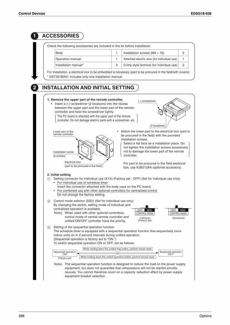
Control Devices EDSG18-936
2 GNITTES LAITINI DNA NOITALLATSNI
1 SEIROSSECCA
.)srevoc htiw/dleif eht ni derucorp eb ot trap( yrassecen si deddebme eb ot xob lacirtcele a ,noitallatsnl roF
* .launam noitallatsni eno ylno sedulcni 16AB103TSD
.noitallatsni erofeb tik eht ni dedulcni era seirossecca gniwollof eht kcehC
eht fo trap rewoLrellortnoc etomer
wercs noitallatsnI
)swercs 2(
xob lacirtcelE
).dlerf eht ni derucorp eb ot trap(
noitarepo laitneuqeS”NO“
)tes yrotcaF(
noitarepo laitneuqeS”FFO“
.teser decrof mrofrep ,nottub pots deifinu eht nwod gnidloh elihW
.teser decrof mrofrep ,nottub noitarepo deifinu eht nwod gnidloh elihW
ylppus rewop eht no daol eht ecuder ot dengised si noitcnuf noitarepo laitneuqes ehT)etoN-atlumis detrats eb ton lliw srosserpmoc taht eetnarauq ton seod tub ,tnempiuqe
ylppus rewop yb tceffe noitcuder yticapac a no tnuoc erofereht tonnac uoY .ylsuoen.noitceles rekaerb tnempiuqe
(– revirdwercs )
)snoitacol 2(
gnittes laitinI .2 )ylno esu laudividni rof teS( )FFO : tes yrotcaF( )A1X( esu laudividni rof rotcennoc gnitteS
• remit eludehcs fo esu laudividni roF.draob CP eht no esac ydob eht htiw dehcatta rotcennoc eht tresnI
• lortnoc dezilartnec rof srellortnoc lanoitpo rehto htiw esu denibmoc roF.gnittes yrotcaf eht egnahc ton oD
)ylno esu laudividni rof teS( )2SS( rotceles edom lortnoCdna laudividni fo edom gnittes ,hctiws eht gnignahc yB
.elbaliava si noitarepo dezilartnec,srellortnoc lanoitpo rehto htiw desu nehW)etoN
dna rellortnoc etomer lartnec fo edom lortnoc.ytiroirp eht evah rellortnoc FFO/NO deifinu
noitcnuf noitarepo laitneuqes eht fo gnitteSsnrut yllaitneuqes taht noitcnuf noitarepo laitneuqes a htiw deppiuqe si remit eludehcs ehT
.noitarepo deifinu gnirud slavretni dnoces-2 ni no stinu roodni ot tes yrotcaf si noitarepo laitneuqeS( “ .NO ”)
.swollof sa tes ,FFO ro NO noitarepo laitneuqes hctiws oT
EDOM LORTNOC.TNEC INDIV.
EDOM LORTNOC.TNEC INDIV.
laudividnI)tes yrotcaF(
dezilartneC
• ot trap( xob lacirtcele eht ot trap rewol eht hcattAdedivorp eht htiw )dleif eht ni derucorp eb
.swercs noitallatsnioD .ecalp noitallatsni a sa ecaf talf a tceleS
ylevissecxe swercs noitallatsni eht nethgit tonetomer eht fo trap rewol eht egamad ot ton
.rellortnoc
lacirtcele dleif eht ni derucorp eb ot trap roF.)yrossecca lanoitpo( AA212BJK esu ,xob
4M( swercs noitallatsnI × 2)61
)esu laudividni rof( eriw cirtcele dehcattA 1
)esu laudividni rof( lanimret elyts pmirC 2
1ydoB
1launam noitarepO
4*launam noitallatsnI
.rellortnoc etomer eht fo trap reppu eht evomeR.1• ( a tresnI – ssecer eht otni )snoitacol 2( revirdwercs )
etomer eht fo trap rewol eht dna trap reppu eht neewteb.ylthgil revirdwercs eht tsiwt dna rellortnoc
etomer eht fo trap reppu eht htiw dehcatta si draob CP ehT.cte ,revirdwercs a htiw strap cirtcele egamad ton oD .rellortnoc
398 Options

EDSG18-936 Control Devices
5
TESEROFF NO
TESEROFF NO
edis teseRedis lamroN
)tes yrotcaF(
rotcennoc gnittes esu laudividnI
htiw esu denibmoc fo esac nI rof srellortnoc lanoitpo rehto
lortnoc dezilartnec )tes yrotcaF(
fo esu laudividni fo esac nIremit eludehcs
A1XA1X.rotceles edom lortnoC
hctiws teser decroF
)1SS( hctiws teser decroFteser eb nac hctiws eht ,.cte ,esu laudividni rof rotcennoc eht fo gnittes eht gnignahc nehW
erudecorp sihT .edis lamron eht ot gninruter dna ecno edis teser eht ot ti gnittes yb ylpmis).noitarepo lamron ta edis lamron eht teS( .rewop eht ffo gninrut tuohtiw teser ot selbane
:SETON.dehcatta ton era gniriw noissimsnart dna xob lacirtcelE.1
.dnah ruoy htiw draob CP eht hcuot ton oD.2rewop morf yawa mm 05 tsael ta gniriw noissimsnart peeK.3
.snoitcnuflam diova ot gniriw ylppus
rellortnoc etomer eht fo trap reppu eht llatsnI .4.erofeb sa
remit eludehcS tinu roodnI
2F1F2D1D 2F1FN C
lanimret elyts pmirClanimret elyts pmirC
remit eludehcs oT2D dna 1D
gniriw dleiF
no rotcennoc eht oTdraob CP tinu roodni
pmalc yleruces ot loot reporp a esU.slanimret elyts pmirc
eriw dehcattA
rehto oTtinu roodni
rehto oTtinu roodtuo
A81X oT:VRVA53X oT
)epyt L-FXF roF ylnO(A53X oT:YKS
yam retpada noitcennoc ehT rof yrassecen yletarapes eb
.riA ykS htiw noitcennoc eht
dhecattAeriw cirtcele
remit eludehcS
2F1F2D1D
etomer lartneCdeifinu(rellortnoc
)rellortnocFFO/NO
2D1D2T1T2F1F
.tsrif walc rewol eht tiF
1
2
1J
1J
noitcnuf laiceps rof gnitteSdemmargorp a evah ot tnaw uoy nehW
yb stinu roodni fo trap a fo noitarepo1PJ ffo tuc ,remit eludehcs ylno gnisu
.niaga rewop eht ylppus dnanoitarepo demmargorp a evah nac uoY
rof sserdda eht tes stinu roodni eht fo.rellortnoc etomer lacol yb lortnoc lartnec
gniriw noissimsnarT .3• remit eludehcs fo esu laudividni fo esac nI
.1F( remit eludehcs eht fo slanimret tcennoC.)2F .1F( tinu roodni eht fo slanimret htiw )2F.1D( remit eludehcs eht fo slanimret tcennoC
CP tinu roodni eht no rotcennoc eht dna )2Ddna eriw cirtcele dehcatta eht gnisu ,draob
.slanimret elyts pmircelyts pmirc fo trap noitcennoc eht tneverP
strap cirtcele eht fo tuo gnitteg morf lanimret.tinu roodni fo xob
• lanoitpo rehto htiw esu denibmoc fo esac nIlortnoc dezilartnec rof srellortnoc
,1F( remit eludehcs eht fo slanimret tcennoClartnec eht fo slanimret eht dna )2D ,1D ,2F
FFO/NO deifinu ro( rellortnoc etomer.)rellortnoc
snoitacificeps gniriW
2F ,1F
)eriw-2( eriw dehtaehS
mm52.1 ~ 57.0 2
m0001 .xaM
gniriW
eguaG
htgneL
2D ,1D
)eriw-2( eriw dehtaehS
mm52.1 ~ 57.0 2
m051 .xaM
Options 399
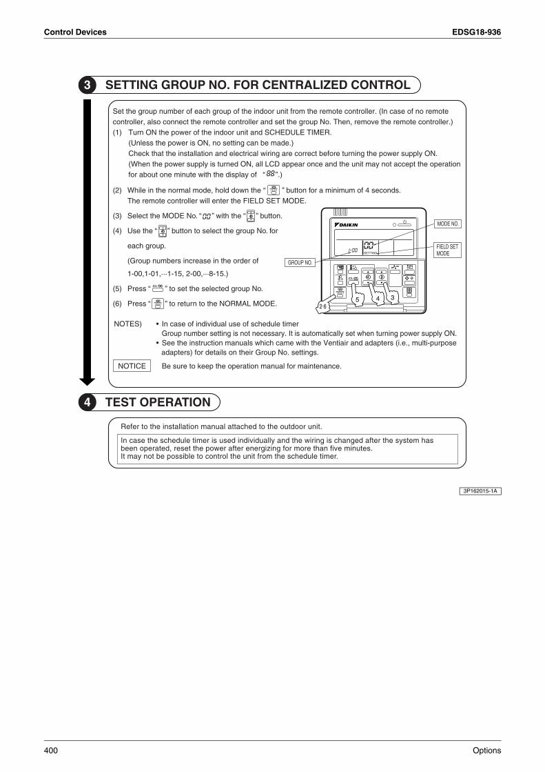
Control Devices EDSG18-936
4 NOITAREPO TSET
3 LORTNOC DEZILARTNEC ROF .ON PUORG GNITTES
.tinu roodtuo eht ot dehcatta launam noitallatsni eht ot refeR
sah metsys eht retfa degnahc si gniriw eht dna yllaudividni desu si remit eludehcs eht esac nI.setunim evif naht erom rof gnizigrene retfa rewop eht teser ,detarepo neeb
.remit eludehcs eht morf tinu eht lortnoc ot elbissop eb ton yam tI
etomer on fo esac nI( .rellortnoc etomer eht morf tinu roodni eht fo puorg hcae fo rebmun puorg eht teS).rellortnoc etomer eht evomer ,nehT .oN puorg eht tes dna rellortnoc etomer eht tcennoc osla ,rellortnoc
.REMIT ELUDEHCS dna tinu roodni eht fo rewop eht NO nruT)1().edam eb nac gnittes on ,NO si rewop eht sselnU(
.NO ylppus rewop eht gninrut erofeb tcerroc era gniriw lacirtcele dna noitallatsni eht taht kcehC noitarepo eht tpecca ton yam tinu eht dna ecno raeppa DCL lla ,NO denrut si ylppus rewop eht nehW(
fo yalpsid eht htiw etunim eno tuoba rof “ ” ).
)SETON • remit eludehcs fo esu laudividni fo esac nI.NO ylppus rewop gninrut nehw tes yllacitamotua si tI .yrassecen ton si gnittes rebmun puorG
• esoprup-itlum ,.e.i( sretpada dna riaitneV eht htiw emac hcihw slaunam noitcurtsni eht eeS.sgnittes .oN puorG rieht no sliated rof )sretpada
.ecnanetniam rof launam noitarepo eht peek ot erus eBECITON
eht nwod dloh ,edom lamron eht ni elihW)2( “ ” .sdnoces 4 fo muminim a rof nottub .EDOM TES DLEIF eht retne lliw rellortnoc etomer ehT
.oN EDOM eht tceleS)3( “ ” eht htiw “ ” .nottub
eht esU)4( “ ” rof .oN puorg eht tceles ot nottub
.puorg hcae
fo redro eht ni esaercni srebmun puorG(
,10-1,00-1 ... ,00-2 ,51-1 ... ).51-8
sserP)5( “ ” .oN puorg detceles eht tes ot
sserP )6( “ ” .EDOM LAMRON eht ot nruter ot
.ON PUORG
.ON EDOM
TES DLEIFEDOM
TSET
GNITTES
342.6
5
TSET
TSET
3P162015-1A
400 Options

EDSG18-936 Control Devices
5
4.3.3 Operation Manual
[1]
1 2364
9
7
8
10 11
5
DST301BA61
1715 1412
13 18 19 20
16
DST301BA61
1
2
Options 401
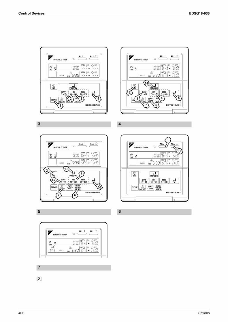
Control Devices EDSG18-936
[2]
1
2 3 4
DST301BA61 7
3
2
1·8
6
4 5
DST301BA61
7 6
2
3·7
1·85
45·6
DST301BA61 DST301BA61
3
7
5
4
6
402 Options

EDSG18-936 Control Devices
5
1
SAFETY CONSIDER-ATIONSPlease read these “ SAFETY CONSIDER-ATIONS ” carefully before installing air condition-ing equipment and be sure to install it correctly. After completing the installation, make sure that the unit operates properly during the start-up operation.Please instruct the customer on how to operate the unit and keep it maintained.Also, inform customers that they should store this installation manual along with the operation manual for future reference.This air conditioner comes under the term “ appli-ances not accessible to the general public ”.
Meaning of warning, caution and note symbols.
WARNING............. Indicates a potentially hazardous situation which, if not avoided, could result in death or serious injury.
CAUTION ............. Indicates a potentially hazardous situation which, if not avoided, may result in minor or moderate injury. It may also be used to alert against unsafe practices.
NOTE ................... Indicates situation that may result in equipment or prop-erty-damage-only accidents.
Keep these warning sheets handy so that you can refer to them if needed.Also, if this equipment is transferred to a new user, make sure to hand over this operation manual to the new user.
WARNING
In order to avoid electric shock, fire or injury, or if you detect any abnormality such as smell of fire, turn off power and call your dealer for instructions.
Ask your dealer for installation of the air conditioner.Incomplete installation performed by your-self may result in a water leakage, electric shock, and fire.
Ask your dealer for improvement, repair, and maintenance.Incomplete improvement, repair, and main-tenance may result in a water leakage, elec-tric shock, and fire.
Improper installation or attachment of equipment or accessories could result in electric shock, short-circuit, leaks, fire or other damage to the equipment. Be sure only to use accessories made by Daikin which are specifically designed for use with the equipment and have them installed by a professional.
Ask your dealer to move and reinstall the air conditioner or the remote controller. Incomplete installation may result in a water leakage, electric shock, and fire.
Never let the indoor unit or the remote controller get wet. It may cause an electric shock or a fire.
Never use flammable spray such as hair spray, lacquer or paint near the unit.It may cause a fire.
Never replace a fuse with that of wrong ampere ratings or other wires when a fuse blows out.Use of wire or copper wire may cause the unit to break down or cause a fire.
Never inspect or service the unit by your-self.Ask a qualified service person to perform this work.
Cut off all electric waves before mainte-nance.
Do not wash the air conditioner or the remote controller with excessive water.Electric shock or fire may result.
Do not install the air conditioner or the remote controller at any place where flammable gas may leak out.If the gas leaks out and stays around the air conditioner, a fire may break out.
Do not touch the switch with wet fingers.Touching a switch with wet fingers can cause electric shock.
CISPR 22 Class A Warning:This is a class A product. In a domestic envi-ronment this product may cause radio inter-ference in which case the user may be required to take adequate measures.
Options 403

Control Devices EDSG18-936
2
CAUTION
After a long use, check the unit stand and fitting for damage.If they are left in a damaged condition, the unit may fall and result in injury.
Do not allow a child to mount on the unit or avoid placing any object on it.Falling or tumbling may result in injury.
Do not let children play on and around the unit.If they touch the unit carelessly, it may result in injury.
Do not place a flower vase and anything containing water.Water may enter the unit, causing an electric shock or fire.
Never touch the internal parts of the con-troller.Do not remove the front panel. Some parts inside are dangerous to touch, and a machine trouble may happen. For checking and adjusting the internal parts, contact your dealer.
Avoid placing the controller in a spot splashed with water.Water coming inside the machine may cause an electric leak or may damage the internal electronic parts.
Do not operate the air conditioner when using a room fumigation - type insecticide.Failure to observe could cause the chemi-cals to become deposited in the unit, which could endanger the health of those who are hypersensitive to chemicals.
Safely dispose of the packing materials.Packing materials, such as nails and other metal or wooden parts, may cause stabs or other injuries.Tear apart and throw away plastic packaging bags so that children will not play with them. If children play with a plastic bag which was not torn apart, they face the risk of suffocation.
Do not turn off the power immediately after stopping operation.Always wait at least five minutes before turn-ing off the power. Otherwise, water leakage and trouble may occur.
The appliance is not intended for use by young children or infirm persons without supervision.
The remote controller should be installed in such away that children cannot play with it.
NOTE
Never press the button of the remote con-troller with a hard, pointed object.The remote controller may be damaged.
Never pull or twist the electric wire of the remote controller.It may cause the unit to malfunction.
Do not place the controller exposed to direct sunlight.The LCD display may get discolored, failing to display the data.
Do not wipe the controller operation panel with benzine, thinner, chemical dustcloth, etc.The panel may get discolored or the coating peeled off. If it is heavily dirty, soak a cloth in water-diluted neutral detergent, squeeze it well and wipe the panel clean. And wipe it with another dry cloth.
Dismantling of the unit, treatment of the refrigerant, oil and eventual other parts, should be done in accordance with the relevant local and national regulations.
404 Options

EDSG18-936 Control Devices
5
3
CONTENTS
SAFETY CONSIDERATIONS...........1
FEATURES AND FUNCTIONS........3
NAMES AND FUNCTIONS OF
OPERATING SECTION.......................4
OPERATION.............................................5
Setting present time........................................5Setting no. of programmed time......................6
Change and cancellation of no. of programmed time............................................7Manual operation ............................................9Operation control code ...................................9Error diagnosing function................................9
QUESTION AND ANSWER.............10
SPECIFICATIONS ...............................12
Specifications................................................12Outline drawings ...........................................12
FEATURES AND FUNCTIONS
• When used in conjunction with central remote controller (Optional Accessory)The operation controlled by programmed time can be set for up to eight different patterns (timer No. 1 – 8). Each schedule pattern can be also selected.
Operation controlled by programmed timeOperating time and stopping time can be set to the minute by each day of the week. The operating and stopping patterns can also be set in schedule according to the time slot given twice a day in tune with the uses.
Unified Operation/StopBy using this schedule timer, the unified operation/stop of the indoor unit can be executed manually regardless of the No. of programmed time in operation.
See page5—9.
See page 9.
Options 405

Control Devices EDSG18-936
4
NAMES AND FUNCTIONS OF OPERATING SECTION (Fig. 1, 2)
1
UNIFIED OPERATION BUT-
TON “ ”
Press this button to perform the unified operation regardless of the No. of pro-grammed time.
2
UNIFIED STOP BUTTON
“ ”
Press this button to perform the unified stop regardless of the No. of pro-grammed time.
3OPERATION LAMP (RED)
The light turns on during the operation of the indoor unit.
4
DISPLAY “ ” (TIME NO.)
Displays the time No. only when used in conjunction with the central remote controller.
5
DISPLAY “PROGRAM START.” (PROGRAMMING START)
The light turns on when the timer is programmed.
6
DISPLAY “ OFF ” (HOLIDAY SETTING)
Lights above the day of the week set as holiday. The operation controlled by timer is not available on that day.
7
DISPLAY “ — ” (SETTING OF DAYS OF A WEEK)
Flashes below the day of the week pro-grammed.
8
DISPLAY “ ” (MALFUNC-TION CODE)
Displays the contents of malfunction during the stop due to malfunction.
9
DISPLAY “ ” (PRESENT TIME)
Displays the present day of the week and time.
10
DISPLAY “ ” (PRO-
GRAMMED TIME OF SYSTEM START)
Displays the time programmed to start.
11
DISPLAY “ ” (PRO-GRAMMED TIME OF SYSTEM OFF)
Displays the time programmed to stop.
12 TIME NO. BUTTON “ ”
See page 5–9.
13
CLOCK ADJUSTING
BUTTON “ ”
Press this button to set the present time.
14
PROGRAMMING START
BUTTON “ ”
Press this button to set or check the No. of programmed time. Press it again after you are through with the program.
15
BUTTON FOR SELECTING
DAYS OF A WEEK “ ”
Press this button to select the day of the week.
16
HOUR/MINUTE BUTTON
“ ”
Press this button to adjust the present time and the programmed time.
406 Options

EDSG18-936 Control Devices
5
5
OPERATION
Setting present time (Fig. 3)
(Example) In case of setting Friday, 5:30 p.m.
1. Press the CLOCK ADJUSTING BUTTON. The present time dis-play flashes.
(NOTE)• The present time needs adjusting in case
of turning power supply on for the first time or the occurrence of power failure over the period of 48 hours or more.
2. Press the BUTTON FOR SELECTING DAYS OF A WEEK. Each time the button is pressed, the day display shifts to the right.
(NOTE)• The display “ MON ” follows the display
“ SUN. ”
3. Set the time with the HOUR/MINUTE BUTTON. Each time the HOUR/MINUTE BUTTON is pressed, the display is put forward minute by minute and hour by hour. When the button is kept pressed, the display is put forward continuously.
(NOTES)• After becoming “ AM 11:00 ”, when the
button is pressed, the display becomes “ PM 0:00 ”.
• After becoming “ 59 ” (minute), when the button is pressed, the display becomes “ 00 ” (minute).
4. Press the TIMER ON BUTTON the moment the time signal of TV, radio, telephone, etc. is heard. The mark “ : ” flashes, and the clock starts.
(NOTES)• The clock used is of 12-hour type.• When you turn power supply on, the sys-
tem may display “ ” for about one minute and not start to operate after all the liquid crystal displays appear at a time.
• If the CLOCK ADJUSTING BUTTON is pressed by mistake, press it again to return to the original state. As the clock does not stop, the time indicated by the clock is kept correct. In case of power failure within 48 hours, the clock keeps operating by utilizing the built-in battery.
17TIMER ON BUTTON “ ”
Press this button to set the present time and the programmed time.
18
HOLIDAY SETTING
BUTTON “ ”
Press this button to set holidays.
19
BUTTON FOR COPYING PROGRAM OF PREVIOUS
DAY “ ”
Use this button to set the No. of pro-grammed time same as that of the pre-vious day.
20
PROGRAM CANCELING
BUTTON “ ”
Use this button to set the programmed time to cancel. The display shows “ – ; – – ”.
(Note)1. Please note that all the displays in the fig-
ure appear for explanation purpose or when the cover is open.
1
2
Set the day to Friday.
3
Set the time to 5:30 p.m.
4
Press the TIMER ON BUTTON in tune with the time signal at 5:30 p.m.
Options 407

Control Devices EDSG18-936
6
Setting no. of programmed time
(Fig. 4)
(Example) Time No. 5 (to be programmed only when used in conjunction with the central remote con-troller)
Monday to Friday:Operating from 8:45 a.m. till 5:00 p.m.Operating from 5:15 p.m. till 11:00 p.m.
Saturday and Sunday: Setting the whole day stop oper-ation (application for holidays) controlled by programmed time.
1. Press the PROGRAMMING START BUTTON. Programming is available.The display “ PROGRAM START ” appears, and the display of days of a week flashes.
2. Press the TIME No. BUTTON, and select the desired number.
(NOTE)• Unless used in conjunction with the cen-
tral remote controller, The TIME No. is not displayed and can not be selected.
3. Press the BUTTON FOR SELECTING DAYS OF A WEEK, and set the proper day of the week. Each time you press it, the flash-ing display of days of a week shifts to the right.
(1) Setting programmed time
4. Set the programmed time of system start 1 by using the HOUR/MINUTE BUTTON. Each time the HOUR/MINUTE BUTTON is pressed, the display is put forward minute by minute and hour by hour. When the button is kept pressed, the display is put forward continuously.
5. Press the TIMER ON BUTTON, and set the programmed time of system start 1. Each time you press it, the next area to be set flashes.
(NOTE)• Set the other programmed time in the
same procedure.
1
2
Select the TIME No. 5.
3
Set to Monday.
4
Set the “PROGRAMMED TIME OF SYSTEM START 1” at 8:45 a.m.
5
408 Options

EDSG18-936 Control Devices
5
7
(2) Set the next day of the week.Set the day of the week to Tuesday, and copy the program of the previous day (Monday). In the same procedure, set the day of the week to Wednesday through Fri-day in sequence.
6. Press the BUTTON FOR SELECTING DAYS OF A WEEK and set the following day. Press the BUTTON FOR COPYING PRO-GRAM OF PREVIOUS DAY. The same program as that of the imme-diately preceding day of the week is set.
(NOTE)• Repeat each procedure 3 – 5 in the
above when not copying the contents of the previous day.
(3) Holiday setting
7. Press the BUTTON FOR SELECTING DAYS OF A WEEK and set one or more days of the week as holiday. Press the HOLI-DAY SETTING BUTTON, and the display “ OFF ” is displayed at the top of the day of the week. If you press it again, the display returns to the original state.
8. Press the PROGRAMMING START BUTTON, and finish the program setting.
(NOTES)• Unless the button is pressed within 20
minutes, the display will automatically revert back to the original state. In this case, setting contents up to the point where the TIMER ON BUTTON (or HOL-IDAY SETTING BUTTON or BUTTON FOR COPYING PROGRAM OF PREVI-OUS DAY) is pressed will only take effect.
• The display “ PROGRAM START ” and the display of days of a week “ — ” disappears.
• The flashing display goes off, and the No. of programmed time of the present day is displayed. Then the operation controlled by timer starts.
• The operation controlled by timer is exe-cuted even while the program is being set.
Change and cancellation of no.
of programmed time (Fig. 5)
(Example) Time No. 3 (to be set only when used in conjunction with the central remote controller)
1. Press the PROGRAMMING START BUTTON. The program setting is ready. The display “ PROGRAM START ” appears, and the display of days of a week flashes.
2. Press the TIME No. BUTTON, and select the desired No.
6
7
Set Saturday and Sunday as holidays.
8
This is the end of the setting example.
Operating from8:45 a.m. till5:00 p.m.
A: Change/cancel partially (Wednesday)
After operating from 8:45 a.m. till 7:00 p.m., the operation stops.
Operating from5:15 p.m. till11:00 p.m.
B: Cancel the whole (Thursday)
Whole day stop.
1
2
Select the time No. 3.
Options 409

Control Devices EDSG18-936
8
3. Press the BUTTON FOR SELECTING DAYS OF A WEEK, and set the day of the week to be changed. The set No. of pro-grammed time of the day of the week is displayed.
A. Change/cancel partially
4. Press the TIMER ON BUTTON and change, and the display of programmed time flashes. Each time you press it, the next area to be set flashes.
5. Press the HOUR/MINUTE BUTTON and change the pro-grammed time. Press the TIMER ON BUTTON, and finalize the set-ting of change.
6. Press the PROGRAM CAN-CELING BUTTON, and cancel the programmed time. If you press it again, display returns to the origi-nal state. Press the TIMER ON BUTTON to finalize the cancella-tion.
In the same procedure, cancel the programmed time of system off 2.
B. Cancel the whole
7. Press the BUTTON FOR SELECTING DAYS OF A WEEK, and shift to the day of the week to be canceled. Then, press the HOL-IDAY SETTING BUTTON, the dis-play “ OFF ” appears at the top of the particular day of the week. The programmed time is canceled. If you press the button again, the display returns to the original state.
3
Set the day to Wednesday.
4
Shift to the display “PROGRAMMED TIME OF SYSTEM OFF 1”.
5
Change the “PROGRAMMED TIME OF SYSTEM OFF 1” to 7:00 p.m.
6
Shift to the “PROGRAMMED TIME OF SYSTEM START 2”.
Set the “PROGRAMMED TIME OF SYSTEM START 2” to program cancellation.
7
Shift the day of the week to Thursday to set as a holiday.
410 Options

EDSG18-936 Control Devices
5
9
8. Press the PROGRAMMING START BUTTON. The program setting is now finished.
(NOTES)• Unless the button is pressed within 20
minutes, the display will automatically revert back to the original state. In this case, setting contents to the point where the TIMER ON BUTTON (or HOLIDAY SETTING BUTTON or BUTTON FOR COPYING PROGRAM OF PREVIOUS DAY) is pressed will only take effect.
• To continue the change/cancellation, do not press the PROGRAMMING START BUTTON until all change/cancellation are completed.
• The operation controlled by timer is exe-cuted even while the program is being set.
Manual operation (Fig. 6)This schedule timer enables the operation/stop by pressing the UNIFIED OPERATION/STOP BUTTON in addition to the operation controlled by timer (operation/stop according to the pro-grammed time) at any time.
1. Press the UNIFIED OPERA-TION BUTTON, and the OPERA-TION LAMP turns on.
2. Press the UNIFIED STOP BUT-TON, and the OPERATION LAMP is turned off.
(NOTES)• The operation automatically stops
according to the programmed time of system off even during the manual oper-ation. In the meantime, the operation starts automatically according to the pro-grammed time of system start even dur-ing the stop of operation.
• If the unit is used in conjunction with other optional controllers for centralized control, the OPERATION LAMP of the unit that is not under operation control may be turned on or off a few minutes behind schedule. This shows that the signal is being exchanged, and does not indicate any failure.
Operation control codeTwo different types of operation control codes can be selected when this kit is used indepen-dently (when not used in conjunction with the central remote controller, unified ON/OFF con-troller, etc.).
IndividualIn case where the operation/stop is controlled by both schedule timer and remote controller.
CentralizedThe operation is controlled by the schedule timer alone, and the operation/stop is controlled freely with the remote controller during the pro-grammed time.
(NOTES)• For current settings, contact your DAIKIN
dealer.• To change settings, contact your DAIKIN
dealer.Do not change settings yourself.
Error diagnosing function
(Fig. 7)This schedule timer is provided with the mal-function diagnosing function. The malfunction code flashes if there occurs any malfunction in communication, etc. between and among the optional controllers for centralized control. In addition, the operation lamp also flashes if there occurs any malfunction in communication with the indoor unit. Check the contents of the display and contact your DAIKIN dealer because the signals give you the idea of the trouble area.
8
Operation lamp
Turn on: The light turns on when any of the indoor units is in operation whether the operation is controlled by timer or by hand.
Turn off: The light turns off when all the indoor units stop.
Options 411

Control Devices EDSG18-936
10
QUESTION AND ANSWER
Opera-tion lamp
Malfunc-tion code
Contents of mal-function
Turn off M1
Failure of PC board of schedule timer.
FixesThe following causes are possi-ble. Check each one.1. PC board prob-
lems
Turn on or off
M8
Malfunction of transmission between each optional controllers for centralized con-trol.
FixesCheck all central devices which are connected (e.g., power supply, transmission wiring, etc.).
Turn on or off
MA
Improper combina-tion of optional controllers for cen-tralized control.
FixesThe following causes are possi-ble. Check each one.1. Are all central
devices com-bined correctly?
2. Is the master central connec-tor attached to two or more cen-tral devices?
3. Are there 128 or more indoor units con-nected?
Turn on or off
MC
Address failure of schedule timer.
FixesThe following causes are possible. Check each one.1. Do the control
range addresses in the central remote control-ler overlap?
2. Do the control range addresses in the on/off con-troller overlap?
3. Are there 2 or more schedule timers con-nected?
Flash UE
Malfunction of transmission between indoor unit and optional controllers for cen-tralized control.
FixesInspect all indoor units which are dis-playing an error (e.g., power supply, transmission wiring, etc.).
Flash —
Malfunction in indoor unit (Refer to the malfunction codes of the indoor remote controller, while also read the “ CAUTION FOR SERVICING ” attached to the indoor unit.)
Question Answer
It is possible to make settings twice a day, but is it possible to make only the “ off ” setting?(To avoid forget-ting to turn the unit off.)
Yes. Press the PRO-GRAM CANCELING
BUTTON in the “ ”
section in order to set it to “ OFF ”.
412 Options

EDSG18-936 Control Devices
5
11
Is it possible to set times which straddle days?
Yes, it is possible.Example:Start operation at 5:00 a.m. on SundayStop operation at 6:00 p.m. on Monday
The unit does not turn on even though the set “ on ” time has come.(When using the schedule timer alone)
The following causes are possible.1. Are the “ on ” time
and the “ off ” time set to the same time?
The unit does not turn on even though the set “ on ” time has come.(When using the unit with a central remote controller)
The following causes are possible. Check each one.1. Was the timer num-
ber set with the cen-tral remote controller?Was an incorrect timer number set?
2. Is another timer no. set with the central remote controller set for “ off ” at the same time?
3. Is the operation code set to “ remote control permission timer ” using the central remote controller or the on/off controller?
The unit oper-ates even though that day is set as a holiday.(When using the unit with a central remote controller)
The following causes are possible.1. Is another timer num-
ber set with the cen-tral remote controller set for “ on ” at the same time?(If two timer numbers are set, make sure that the settings for holidays and working days do not overlap between the different timer numbers.)
The TIME NO. is not displayed.
The following causes are possible.1. The TIME NO. is not
displayed when using the schedule timer alone.(It can be set if using the central remote controller at the same time.)
The display remains
“ ”
even though I push the HOUR/MINUTE BUTTON in the timer program settings.
The following causes are possible.1. Is the day set to a
holiday?
I cannot set “ central manage-ment priority ” or “ after-push prior-ity ” with the schedule timer.
The following causes are possible.1. Is a central remote
controller or on/off controller also installed?
∗∗∗∗ The priority order of the operation codes depends on the central devices which are installed.The below operation codes are set. • Schedule timer
Central remote controller is used as wellOperation code of the central remote controller
• Schedule timerOn/off controller is used as wellOperation code of the on/off control-ler
• Schedule timerCentral remote controllerOn/off controller is used as wellOperation code of the central remote controller
3P124623-5C
Options 413

Control Devices EDSG18-936
4.4 Combination of <DCS302CA61 / DCS301BA61 / DST301BA61>Combinations of Optional Controllers for Centralized Control
Besides using the various optional controllers for centralized control by themselves, a schedule timer or unified ON/OFF controller can be combined with and connected to the central remote controller. By devising a component system such as this, you can freely construct the ideal central control system according to use and scale.
4.4.1 System ExampleUnified ON/OFF controller
Connect a unified ON/OFF controller according to the number of indoor units. A network consisting of up to 16 groups×8 units=128 groups can be constructed using a single line.
Schedule timer + central remote controller
Lets you set up to 8 patterns of weekly schedule for turning air-conditioning equipment ON/OFF twice a day. Operates up to 128 groups of indoor units individually or by zone according to a programmed schedule.
Central remote controller + unified ON/OFF controller
Combines the high functionality of a central remote controller and the easy operation of a unified ON/OFF controller. Centrally controls up to 128 groups of indoor units.
Schedule timer + unified ON/OFF controller
Lets you set ON/OFF for twice a day.Operates up to 128 groups of indoor units all together according to a programmed schedule.
Central control adaptor kit (DTA107A55).
Wiring adaptorfor other air-conditioners (DTA103A51)
Central remote controller(DCS302CA61)
Up to 2 units connectable
Unified ON/OFF controller(DCS301BA61)
Connection of up to 8 unitspossible
Schedule timer (DST301BA61)1 unit connection possible ; 8 weekly schedule control patterns possible
Forced shut-down input
Independent and centralized control of HRV is possible.
Unification adaptor for computerized control * (DCS302A52)
Interlink Building Management System (host computer monitor panel) also possible
Note: Certain units limit the functions of some control systems.
6 cores 7 cores max.
Address setting of central control can be performed from the remote controller.
Group control of up to 16 units is possible (group control via automatic address setting)
System without remote control is also available.
Interface adaptor for SkyAir series (built-in indoor unit) (DTA102A52)
Connectable number of centralized control equipment
Central remotecontoroller 2 units
Unified on /offcontoroller 8 units
Schedule timer 1 unit
Outdoor-air processing unit can be connected.
414 Options

EDSG18-936 Control Devices
5
You can freely combine the central controllers within the limitation of the following number of each controller; 1~4 units of central remote controllers, one unit of schedule timer and 1~16 units of unified ON/OFF controllers.However, the maximum number of the indoor units to be controlled is 128 units for one system in any combination of the central controllers.
Connection Pattern for Optional Controller for Centralized Control
The maximum number of indoor units is based on one unit in each zone and is also under the double central control system.
4.4.2 Electric WiringCombination of 1 Central Remote Controller, 1 Schedule Timer, 3 Unified ON/OFF Controllers
Central Remote Controller DCS302CA61 Unified ON/OFF Controllers DCS301BA61 Schedule Timer DST301BA61
1~4
— —
1~16—
1
— 1
Options 415

Control Devices EDSG18-936
4.4.3 Initial Settings for Central Control Equipment1. Central Remote Controller
Leave the master control connector (X1A) connected.(Connected when shipped from the factory)The connector is to be connected to only 1 central line.Operation control settingSets the priority ranking of control for the central remote controller and remote controller for indoor units.Zone settingSets the zones when several groups are controlled as one group.
2. Unified On/Off Controller (No.s 1, 2, and 3 in the figure above)Remove the master control connector (X1A).Control range setting switch (DS1)Sets the range of group No.s for each group of indoor units to be controlled by unified ON/OFF controllers no.1,2 and 3 in the figure above. 16 units (16 groups) can be set by 1 unified ON/OFF controller.Control mode switch (DS2)Sets priority ranking of control for unified ON/OFF controllers and remote controllers for indoor units. If using in combination with a central remote controller, the central remote controllers control mode is given priority.
3. Schedule TimerLeave the setting connector for individual use (X1A) disconnected. (Disconnected when shipped from the factory)Control mode switch (SS2)Sets the priority ranking of control for the schedule timer and remote controllers for indoor units. If using in combination with a central remote controller, the central remote controllers control mode is given priority.
4.4.4 Group No. Setting for Central Control1. Setting by Remote Controller for Indoor Units
Sets group No.s in local setting mode by remote controller. (Group No.s are 1-00~1-15, 2-00~2-15 up to 8-00~8-15)
2. Adaptor PC Board SettingSets group No. setting switches RS1 and RS2 for central control on PC board when using an interface adaptor for SkyAir series, or wiring adaptor for other air-conditioners.RS1 (Upper): 1~4 (1~8 in case of interface adaptor for SkyAir Series)RS2 (Lower): 0~F
416 Options

EDSG18-936 Control Devices
5
4.5 <KRP928B2S> Interface Adaptor for DIII-NET (Residential Air Conditioner)
Safety Precautions
Read these Safety Precautions carefully to ensure correct installation.
This manual classifies precautions into WARNING and CAUTION.
WARNING : Failure to follow WARNING is very likely to result in such grave
consequences as death or serious injury.
CAUTION : Failure to follow CAUTION may result in serious injury or property damage, and in certain circumstances, may result in a grave consequence.
Be sure to follow all the precautions below ; they are all important for ensuring safety.
3.Names of Parts and Electric Wiring
WARNING
CAUTION
After installation is complete, test the operation of the PCB set to check
for problems, and explain how to use the set to the end-user.
1.Overview, Features and Compatible Models
This kit is the interface required when connecting the central controller and a Daikin Room Air Conditioner. Use of the central controller makes it possible to perform the following monitoring and operations. It is compatible with room air conditioners which have an HA connector S21.
Precaution1.When reading the Operating / error signals, a separate external power source
(DC 12V) is needed.2.A separate timer power source (DC 16V) is needed when using the schedule
timer independently, and not in conjunction with other central controllers.3.The range of temperatures that can be set from the central controller is 18°C to
32°C in cooling and 14°C to 28°C in heating.4.Fan operation cannot be selected from the central controller or wired remote controller.5.Group control (i.e., control of multiple indoor units with a single remote controller) is
not available.6.Monitoring is not available of the thermo status, compressor operating status,
indoor fan operating status, electric heater, or humidifier operating status.7.Forced thermo off, filter sign display and reset, fan direction and speed settings,
air conditioning fee management, energy savings instructions, low-noise instructions, and demand instructions cannot be made.
1.Run / stop for the central controller and wired remote controller, operating mode selection, and temperature can be set.
2.The operating status, any errors, and the content of those errors can be monitored from the central controller and wired remote controller.
3.Run / stop for the central controller and wireless remote controller, operating mode selection, and the temperature setting can be limited by the central controller.
4.Zone control can be performed from the central controller.5.The unit can remember the operating status of the air conditioner before a power
outage and then start operating in the same status when the power comes back on.
6.Card keys, operating control panels, and other constant / instantaneous connection-compatible equipment can be connected.
7.The Operating / error signals can be read.8.HA JEM-A-compatible equipment can be connected.9.The indoor temperature can be monitored from the Ve-up controller.
2.Component Parts and Separately-Sold Parts which are RequiredThis kit includes the following components. Check to ensure that none of these are missing.
1 2 3 4 1 2 3 4
12
34
1
0
ON
OFF
ON
OF
F
SW1
S16S19
S6
F1
SW2
SW3
LED1
Tes1 S1 S8 S5
F2
Once the switches are set and the wiring complete, secure the case using the included screws.
A cable field supply A cable field supply
In case that the device coping with HA JEM-A is connected
Connecting a Wired Remote Controller
In case that a central remote controller is connected
Connecting a Momentary / constant Contact Input Equipment
Reading the Operating / error Display
Tele-con (Field supply)Remote controller
BRC944 SeriesCard key(Field supply)Operating control panel(Field supply)
KRC65, KRC72, KDC100A10, and KDC101B Series cannot be connected.
The adapter included with the remote controller is not used.
DAIKIN
<Wiring procedure>
Supplied connection harness
Installation should be left to the dealer or another qualified professional.Improper installation by yourself may cause malfunction, electrical shock, or fire.
Install the set according to the instructions given in this manual.Incomplete or improper installation may cause malfunction, electrical shock, or fire.
Be sure to use the standard attachments or the genuine parts.Use of other parts may cause malfunction, electrical shock, or fire.
Disconnect power to the connected equipment before starting installation.Failure to do so may cause malfunction, electrical shock, or fire.
An earth leakage circuit breaker should be installed.If the breaker is not installed, electrical shock may occur.
Do not install the set in a location where there is danger of exposure to inflammable gas.Gas accumulated around the unit at the worst may cause fire.
To prevent damage due to electrostatic discharge, touch your hand to a nearby metal object (doorknob, aluminum sash, etc.) to discharge static electricity from your body before touching this kit.Static electricity can damage this kit.
Lay this cable separately from other power cables to avoid external electrical noises.
Screw cover
Non polarity
Included in the Drain Up Kit.
Separately sold remote control code (quadplex)KRCW101A Series
Operating monitoring equipment(Field supply)
PartsKit assyPCB is in the housing.
Q’ty Q’ty
1
Parts
Connection harness (about 1.6m)
Mounting screws
Binding band
Installation manual
1set
3pcs.
1pc.
1set
Room air conditioner indoor unit
To HA connector (S21)
Cable available field supply (See the installation manual of the central remote controller)
Lower group number switch (SW1)
Upper group number switch (SW2-1to 3)
Operation when recovering from a power outage modeswitch (SW2-4)
Service monitor (LED1: green)When the CPU is working properly, the LED flashes.
Power supply terminal (S8)
Connect an external DC 12V power supply only when reading the Operating / error display.
Japanese unit / Overseas unitSetting switch (SW3-3)
Momentary contact / constant contactSelection switch (SW3-2)
Forced stopSettings switch (SW3-1)
Central controller equipmentDCS302 SeriesDCS301 SeriesDCS601 SeriesDST301 Series
Options 417

Control Devices EDSG18-936
4.Switch Settings 5.Control Codes
7.Combining Equipment
6.Read Operating / Error Display Signal
Turn the power on after all the switches have been set. Settings made while the power is on are invalid.NOTE
Overseas ON “Automatic” operation is available from the central controller.
Japan
Destination SW3-3 setting What Happens
OFF(Factory setting)
Open the Kit’s case and set the switches on the circuit board. (1) For Overseas / Japanese unit setting (SW3-3)
Room air conditioners, different methods are used for setting the temperature in automatic mode, so this switch needs to be set.
When using a central remote controller, the operating codes can be used to limit operation from wireless remote controllers.
: permitted; × : prohibited
The Operating / error signals can be read from the contact output (S5).Output specs
M1: Turn MR 1 ON when the air conditioner is running. M2: Turn MR 2 when a communication error has occurred between the KRP928B2S and
the air conditioner, or MR 1 is ON and the unit has stopped after an error.MR 2 is not turned ON during a warning.
(2) Group number settings (SW1 and SW2-1 to SW2-3)Set these when using the central controller. (Set to the side.) Do not set more than one unit to the same number.
However, these settings do not need to be made when using the schedule timer independently. (The settings are needed when used in conjunction with another DCS Series central controller.) In this case, the schedule timer performs an auto address after the power is turned on, so new group numbers are automatically set. Settings made using the switches will be overwritten.
(3) Settings when recovering from a power outage (SW2-4)This selects whether to restart operation when the power comes back on after a power outage occurred during operation. This setting is given priority in cases where the indoor unit has an auto start ON / OFF jumper. Note also that regardless of whether switch SW2-4 is on or off, the operating mode, set temperature, fan direction and speed settings, and remote control prohibition status are stored.
NOTE1: Since central equipment and HA JEM-A-compatible equipment both use last command priority, the contact status and operating status of the air conditioner might not match sometimes.Example: If the unit is run from the central controller while the air
conditioner is stopped with an open contact, the contact will be open and the unit will be running.
NOTE2: Operating mode and fan direction and speed settings can be changed.
(4) Contact input function settings (SW3-1 to SW3-2)When using contact input (S1), choose one of the following functions.
NOTE also that a separate timer power source is needed when using the schedule timer independently.Power source specs: DC 16V, +10%, -15%, 200mA.Recommended power source: Omron S82J-01015A. (Should be used with the output voltage adjusted to the center, DC 16V.)
Uppergroup NO.
1—
2—
3—
4—
5—
6—
7—
8—
1 1 2 3
01 2 3
1 2 3
1 2 3
1 2 3
1 2 3
1 2 3
1 2 3
SW1setting
Lowergroup NO.
0 0
0 1
0 2
0 3
0 4
0 5
0 6
0 7
1 1 2 3
01 2 3
1 2 3
1 2 3
1 2 3
1 2 3
1 2 3
1 2 3
4
4
4
4
4
4
4
4
SW1setting
Lowergroup NO.
0 8
0 9
1 0
1 1
1 2
1 3
1 4
1 5
1 2 3
1 2 3
1 2 3
1 2 3
1 2 3
1 2 3
1 2 3
1 2 3
4
4
4
4
4
4
4
4
Stops if the unit was stopped before the power outage and runs if it was running.
Stops after recovering from a power outageOFF
(Factory setting)
ON
SW2-4 setting What Happens
ON / OFF control is rejected (operate / stop / timer prohibition) (NOTE 2).During a forced stop, all remote controller actions are prohibited.
Last command priority
Contact - Open to close: air condition stops (forced stop). Close to open: no change in operating status.
Contact - Open to close: air condition runs.Close to open: air conditioner is stopped (NOTE 1).
Constant contact input
Forced stop or remote controller permission input
The operating status of the air conditioner is reversed by an instantaneous input of 100 msec or more.
Instantaneous contact input (factory setting)
What Happens Control modeS1operating mode
SW3-2setting
SW3-1setting
OFF
OFF
ON
ON Invalid
Run / stop InputContact specsNo-voltage minute electric current contact (Minimum applicable load DC 12V, 1mA or lower)
Total wire length max: 100m
KRP928B2S
S1CA
CB
Forced stop
Timer operation is accepted by remote controller
Last command priority
Only OFF control is accepted
ON / OFF control is rejected
Control mode
Constantcontact mode
Instantaneouscontact mode
S1operating
mode
Operations from central controller, contact input and HA JEM-A input
10,11
6,7
8
9
212–19
0,1,3
45
48
2,10-190,1,3,5-7
Controlcode
“Stop” control from the central controller
“Run” control from the central controller
Operations from the remote controller
× ×××××××
Central priority
××***
××
×××
××
×
×××
××***
××
××
×
×
*
×
×
××
××
Run
/ tim
er
Run
/ tim
er
Fan
dire
ctio
n an
d fa
n sp
eed
Fan
dire
ctio
n an
d fa
n sp
eed
Sto
p
Sto
p
Ope
ratin
g m
ode
tem
pera
ture
Ope
ratin
g m
ode
tem
pera
ture
t
×Wireless Remote Controller
××Wired Remote Controller
×HA JEM-A-compatible equipment
×××Instantaneous contact input
×××Constant contact input
×××Forced stop contact input
××D-BIPS
××Schedule timer
ON / OFF controller
ON
/ O
FF
con
trol
ler
Central Remote Controller
S8 Power supply for relay (DC 12V)
Power source for display
Relay specs (MR1 and MR2) Coil voltage: DC 12V
Coil resistance: 160Ω ± 10% (Matsushita Electric HC Relay, Omron MY Relay)Wiring length Max: 100m
KRP928B2S
S5
MC
M1
M2
(+)
(–)
(–)
MR1
MR2
Operating Display
Abnormality display
Operating control panel (Field supply)
MR1
MR2
The remote controller permission / prohibition settings using the Ve-up controller are as follows.
: permitted; × : prohibited
Forced stop
Constantcontact mode
Constantcontact mode
Instantaneouscontact mode
Instantaneouscontact mode Last command
priority
Does not affect settings
permitted/prohibitedpermitted/prohibited
××
×× ×
prohibitedpermitted
prohibitedpermitted
× × × ×
Operations from central controller, contact input and HA JEM-A input
permitted/prohibitedpermitted/prohibited
permittedprohibited
× ×
prohibited
permitted
Only OFF control is accepted
permitted/prohibited
permitted/prohibited
permittedprohibited
×××× × ×
×
××prohibited
permitted
ON / OFF control is rejected
Start / stop Change operating mode
Change set temperature Run / timer
Operating mode temperature
Fan direction and fan speedStop
Operations from the remote controllerVe-up controller settings
Instantaneouscontact mode
•Constant
contact mode
S1 pin operating mode
permitted/prohibited
permitted/prohibited
×
×
×
× ×prohibited
permitted
“Automatic” operation is not available from the central controller. When using “automatic” operation using the wireless remote controller, the central controller displays automatic cooling (heating) and 25°C. Even if the temperature is changed, it will return to 25°C after a while.
SW2setting
Cen
tral
Rem
ote
Con
trol
ler
Sch
edul
e tim
er
D-B
IPS
For
ced
stop
con
tact
inpu
t
Con
stan
t con
tact
inpu
t
Inst
anta
neou
s co
ntac
t inp
ut
HA J
EM-A
-com
patib
le e
quip
men
t
Wire
d R
emot
e C
ontr
olle
r
Wire
less
Rem
ote
Con
trolle
r
The central controller can be combined with the following devices.
9 *
×
××
*Only during timer operation
3P157704-2B
418 Options
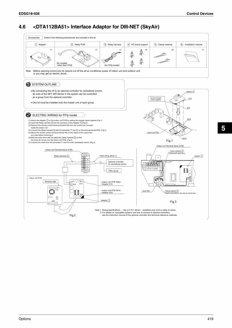
EDSG18-936 Control Devices
5
4.6 <DTA112BA51> Interface Adaptor for DIII-NET (SkyAir)
Accessories
SYSTEM OUTLINE
Note Before opening control box lid, besure cut off the all air conditioner power of indoor unit and outdoor unit,
• By connecting this kit to an optional controller for centralized control,
as a group from the optional controller.
• One kit must be installed onto the master unit of each group.
all units of the SKY AIR Series in the system can be controlled
or you may get an electric shock..
Check if the following accessories are included in the kit.
1 Adaptor
×1
(for modelsother than FFQ)
2 Relay PCB
×1
3
(for FFQ model)
Relay harness
×1
4 PC board support
×4
5 Clamp material
×2
6 Installation manual
×1
P1P2
F1F2
F2F1P2P1
Clamp material 5
Indoor unit Terminal block (X1M)
Adaptor 1
X60A
X61A
Adaptor 1
Noise filter
X3A
ELECTRIC WIRING for FFQ model
X2A
Set the trianglemarks together
Indoor unit PCB
X1A
Clamp material 5
Optional controllerfor centralized control
Field wiring (Note.1)
X2A
Other group
X1A • Indoor unit PCB X61A• Adaptor X2A
Reverse side
Indoor unit Terminal block (X1M)
• Indoor unit PCB X60A• Adaptor X1AX1A
Fig.2
X2A
Relay harness 3
Indoor unit PCB
adaptor 1
X3A
(Clamp with earth wire)
(1) Mount the Adapter 1 on the indoor unit PCB by setting the triangle marks together.(Fig.1)(2) Insert the Relay harness 3 into the connector of the Adapter 1 (Fig.2)(3) Remove the remote control terminal block(X1M) from the control box mounted
inside the indoor unit.(4) Connect the Relay harness 3 with the terminals F1 and F2 on the terminal block(X1M). (Fig.2)(5) Mount the remote control terminal block(X1M) on the inside of the control box
as it was before removing it.(6) Bind the extra wires with the attached Clamp material 5 so that
the wires do not go over the indoor unit PCB. (Fig.3)(7) Connect the wires from the terminals F1 and F2 to the centralized control. (Fig.2)
Fig.3
(Clamp noise filter to the side of control box)
Note 1. Wiring specifications ... Use a 0.75-1.25mm sheathed vinyl cord or cable (2 wires).2. For details on compatible systems and how to connect to optional controllers,
see the instruction manual of the optional controller and technical reference materials.
Fig.1
Options 419

Control Devices EDSG18-936
ELECTRIC WIRING for FFQ model
for centralized controlOptional controller
F1
F2
· Adaptor X1A· Indoor unit PCB X60A
X2A
Relay PCB 2
X2A
· Adaptor X2A· Indoor unit PCB X61A
Fig.4
X1A
Other group
adaptor 1
Reverse sideX3A
X1A
Indoor unit PCB
Field wiring (Note.1)
Bind the extra wire
Indoor unit PCB
Control box
Relay PCB 2
Relay PCB 2
Control box
Indoor unit PCBBind the extra wire
PC board support 4
PC board support 4
(Multi Flow Type)FCQ FBQ
<Ceiling Mounted Cassette Type>
Installation position of Relay PCB
<Ceiling Mounted Built-In Type>
see the instruction manual of the optional controller and technical reference materials.2. For details on compatible systems and how to connect to optional controllers,
Note1. Wiring specifications ... Use a 0.75-1.25mm sheathed vinyl cord or cable (2 wires).
(5) Connect the wires from the terminals F1 and F2 to the centralized control. (Fig.4)the indoor unit PCB and the parts on the PCB do not get damaged.
(4) Bind the extra wires with the attached Clamp material 5 so that the wires do not go overInstalle position of Relay PCB.
(3) Mount the Relay PCB 2 on the required location referring to the figure of(2) Insert the harness from Relay PCB 2 into the connector (X3A) of the Adapter 1 .(Fig.4)
together. (Fig. 1 )(1) Mount the adapter 1 on the indoor unit PCB by setting the triangle marks
ELECTRIC WIRING for MODELS OTHER THAN FFQ3
C : 1P107904-1C
420 Options

EDSG18-936 Control Devices
5
4.7 <KRC72> Centralized Control Board-up to 5 RoomsPossible to control max. 5 Room Air conditioners with centralized function. This is a low cost system which can only control about ON/OFF.
4.7.1 Appearance and Functions
Accessories Indispensable Optional Accessories
External Dimensions Controller
Centralized control can apply to max. 5 Room Air conditioners handling from one location.Contribute to save energy by eliminating turn-off of lamps.Possible to control the action of ON/OFF individually for each Room Air conditioner. (Last command priority is adopted from either an indoor remote controller or a home controller.)It understands an operation situation with the operation display lamp.
Central remote controller for 5 Room Air conditioners <KRC72>Remote control PC board <KRP413A1S>JIS three-throw switch box (Field supply).
Lower casing × 1 Control panel × 1
Room label × 1
M4 truss small screw × 6
Manual × 1(Q0086)
Room label(Q0214)
A
137
120
23
168
120
70
8 332
46 46
83.5
5-6φhole
A arrow view
(Q0087)
Room labelPut each room's label
Operation LampLighted up when each Room Airconditioner is operating. Operation switch
Repeats ON and OFF every time to be pushed.(see Note.)
Note: Possible to operate from either a home controller or each Room Airconditioner.
(Q0088)
Options 421

Control Devices EDSG18-936
4.7.2 Wiring Example
Key PointsConnect to the terminal number 1 ~ 4 on the control panel as shown below.
Switch Setting of KRP413A1SChoose the action mode 1 by switching SW1-1 to OFF.
E4E3E2E1D4D3D2D1C4C3C2C1B4B3B2B1A4A3A2A1
2121
S4S1
E room's airconditioner
Terminal strip
Terminal strip Main body control PC board
Transmission wiring: four wires
Main body of airconditionerController box KRC72
PC board for remote control adapter KRP413A1S
Connection of connectors(Connector No.: S21)
D room's airconditioner
C room's airconditioner
A room's airconditioner
B room's airconditioner
Transmission wiring length : 50 m or less/unittotally within 250 m
Note: Switches of control panel are named A,B,C,D,E counted from the right.
(Q0089)
To connector S21 on the PC board of indoor unit
Controller boxKRC72
50
51
52
A4
A3
A2
A1
S
7
S3
S6(5P)
SW2
SW1
ONOFF
1 2 3 4
1
2
S2
1
212
S1
1
2
S4
1
2S8
+
-
S5
1
2
3
ON OFF
Monitor Normal
(Q0090)
SW1ONOFF
1 2(Q0091)
422 Options

EDSG18-936 Control Devices
5
4.8 <KRP413A1S> Wiring Adaptor for Timer Clock / Remote Controller
1. Functions and Features
On/Off settingSwitching between Instantaneous Contact/Normal ContactConnection with five-room central controller (KRC72 for oversea model)Connection with fan coil remote controllerAutomatic reset after power failureOutput of normal operation signals/malfunction signals
2. Field Wiring
For interconnecting wiring, use Daikin KDC100A12 cable (not supplied) orother similar cable. The cable should have the specifications shown below.
Optional cable KDC100A12 (without connectors)Specifications: 0.2 mm2 × 4 core (sheathed)Outer diameter: φ 5.3Length: 100 mColour: Grey
Other cable (commercially available)
Item
Cable for instrumentation (IPVV) 0.3 mm2 × 4-core
Microphone cord (MVVS) 0.3 mm2 ×
×
×
×
×
4-core
Microphone cord (MVVS) 0.2 mm2 4-core
Microphone cord (MVVS) 0.15 mm2 4-core
Intercom cable 0.65 mm2 dia. 4-core
PVC jumper wire (TJVC) (from 0.5 mm dia. 4 pcs.)
Outer dia.
7.2 mm
8.0 mm
6.5 mm
4.8 mm
—
Remarks
Hard sheath
Shielded
Not sheathed
Note 1: Keep any wiring for the control unit away from the power cord to preventelectrical noise.
Note 2: Do not use cables shown above for power cord, inter-unit cord/cable orpower cord for lamps.
Safety Precautions
Read these safety precautions carefully before installing the unit, and besure to install the unit properly.This manual classifies precautions to the user into the following twocategories. These warnings and cautions are for your safety. Follow them.
WARNING
CAUTION
Faulty installation can result in death or serious injury
Faulty installation can result in serious injuryor other serious consequences.
Below is a key to symbols used in this manual.
Be sure to follow instructions.
Be sure to perform grounding work.
Never attempt.
After installation is complete, test the unit to confirm that it is workingproperly, and instruct the owner its proper use.
WARNING
Installation should be left to the dealer from whom you purchased the unit, oranother qualified professionals.Install the unit securely according to the installation manual. Faulty installationmay lead to electric shock or fire.Be sure to use the supplied or specified parts. Using other parts may lead toelectric shock or fire.Install the unit securely in a location that will support its weight. If installed in apoor location or improperly installed, the unit may not work as intended.For electrical work, follow local electric standards and the installation manual.Faulty installation may lead to fire or electric shock.Do not bundle the power cord, or attempt to extend it by splicing it with anothercord or by using an extension cord. Do not place any other load on the powercircuit used for the unit. Improper wiring may lead to electric shock, heatgeneration or fire.Use dedicated wiring for all electrical connections, and be sure to arrange thewiring so that force applied to the wiring will not damage the terminals. Poorwiring or installation may cause electric shock, heat generation or fire.
CAUTION
Before installation, unplug the air conditioner to ensure safety. Failure to do somay cause electric shock.Static electricity may damage electric components. Before connecting cablesand communication lines, and operating the switches, be sure to discharge anyelectrical charge from your body (by, for example, touching the earth line)Do not install the unit in a location where it may be exposed to flammablegases. If gas leaks and build up around the unit, it may catch fire.Do not place the wiring close to the power cord, inter-unit cable, or pipes whichgenerate noise. Treat the wiring with care.
Options 423

Control Devices EDSG18-936
Installation
This product is available in two types. The KRP413A1S · KRP413AA1S is for installation in a case independent of the indoor unit, andthe KRP413A1 is for installation within the indoor unit.
1. KRP413A1S · KRP413AA1S
1 Installation diagram
Indoor unit PCB
Adaptor case
wiringLocal wiring or power cord, etc.
S21
2 Components
Adaptor case assy Wiring (approx. 0.8 m)(Adaptor (PCB) is attached in the adaptor case.)
Accessories• Binding band (4 pcs.)• Securing tape for attaching to the indoor unit (2 sets)• Screws for attaching the adaptor case (4 pcs.)• Screws for attaching to the wall (3 pcs.)
Installation manual
2. KRP413A1
For this type, install the adaptor PCB within the indoor unit. The method ofinstallation and connection vary depending on the model of the airconditioner. See your air conditioner installation manual for details.
1 Components
Adaptor PCB Wiring (approx. 0.25 m)
Installation manual
3. Attaching Adaptor Case Assy (for KRP413A1S · KRP413AA1S)
1 Using the screws (to mount on a wall, etc.)
Use the 3 supplied screws to attach the case assy .
Indoor unitAdaptor case
Install the adaptor case assy as close to the indoor unit as possible.Removing case front
Adaptor PCB
Case front
Screw
Screw cover
Remove the screw cover, one of the screwsand then the case front.Attach the case back to the surface bytightening the screws through the screwholes (one round hole, two long holes).After connecting the cables (refer to the following sections), replace thecase front. Be careful not to damage the wiring in the case.
Wiring
Press in so that the prong catches the case back.
Screw
Screw cover
2 Using securing tape (to attach on the indoor unit)
Attach the adaptor case with the supplied securing tape.Remove the case front (as for mounting on a wall).After connecting the cables (see the following sections), replace thecase front. It can be screwed to the case back from the rear with thefour supplied screws.Be careful not to damage the wiring in the case.Attach the hook side (loop side) of the included securing tape to the rearsurface of the HA case, then attach the loop side (hook side) to the top ofthe air conditioner unit spaced at the same intervals.
Securing tape Hook side (loop side)
Securing tape Loop side (hook side)
Indoor unit
To prevent the adaptor case assy from falling, do not use the securingtape for attaching it to a wall or other surface.
424 Options

EDSG18-936 Control Devices
5
Wiring
1. Wiring
Connect one end of the wiring to connector S21 of the PCB in theindoor unit.Connect the other end of the wiring to connector S6 of the adaptorPCB.Connect field wiring according to the functions assigned to eachconnection terminal of the adaptor PCB.Secure all wires.
1 Securing wires in the adaptor case assy (for KRP413A1S · KRP413AA1S)
Fasten with a tie-wrap so that wires will not come loose even if pulled.
Inter unit cable (field wiring)
Tie-wrap (to prevent the wires from coming loose)
If the wire protrudes from this side, cut the cut-off section of the case front.
2 Securing wires in the indoor unit (for KRP413A1)
The method for securing wire varies depending on the model of the airconditioner. See your air conditioner installation manual for details.
2. Automatic Reset After Power Failure
This PCB stores the following data in the event of a power failure(common features).On/Off (see Note 1) Operation modes Temperature settingAir flow rate On/Off status of remote controller
(Note 1 When SW1-2 is in Off mode, the unit will not be activated.)
3. Monitor Signal Output (normal operation and malfunction)
Maximum length of the wiring is 100 m.
1 Monitor signal output for LED
LED D
R1
2
S4
Max 100 m
2 Monitor signal output (normal operation and malfunction)using external relay contacts
DC12V
MR1
MR2L 1
2L
MR1
MR2
L 1
2L
: Operation light
: Malfunction light
+
(+)
(–)
(–)
–
1
2
3
S8
S5
Max 100 mField supplied parts
External power supply for light
Field procured parts (Recommended external relay contacts)
Manufacturer Type Coil rated voltage Coil resistance
Omron MY relay 12 V DC 160 ohm ± 10%
Matsushita HC relay 12 V DC 160 ohm ± 10%
4. Connection with Remote Controller
Example connections with three kinds of remote controllers are shownbellow.Note: These connections cannot be used in combination.
1 Generic remote controller
Set SW1-1 to Off and select Operation Mode 1.
SW1
ON
OFF1 2
<Instantaneous Contact>
1
2
1
2
S2
S1On/Off
Off
<Normal Contact>
1
2
1
2
S1
S2
Operation
On
2 Five-room central controller (KRC72)
Set SW1-1 to Off and select Operation Mode 1.The remote controller most recently used takes precedence.
Five-room centralcontroller
Terminalblocks A to E
1
2
3
4 1
2
1
2
1 2
SW1ON
OFF
S4
S1
3 Fan coil remote controller
Set SW1-1 to On and select Operation Mode 2.Most settings (power On/Off, air flow rate, mode change) cannot bemade using the air conditioner’s remote controller.When power is restored after a power failure in this mode, On or Off isdetermined according to the current settings of the remote controller.When the Cooling /Heating mode is changed, use the air conditioner’sremote controller to adjust the temperature.
1 2
SW1ON
OFF
S1
1
2
1
2
1
2
S2
S3
H M L OFF
Fan coil remote controller
Off(When cooling)
On (When heating)
Cooling/heating switch
Locally procured parts
Item Manufacturer Type
LED ToshibaTLG208 (green)
TLR208 (red)
D Rohm 1S2473
R 510 ohm 1/4W
The remote controller mostrecently used (local or airconditioner) takes precedence.Use a remote controller with apulse width of 100 msec ormore.
Power On/Off cannot be controlledfrom the unit’s remote controller.When power is restored after apower failure in this mode, On orOff is determined according tothe current settings of the remotecontroller.
Options 425
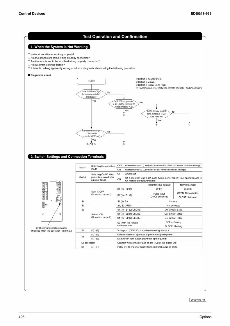
Control Devices EDSG18-936
Test Operation and Confirmation
1. When the System is Not Working
Is the air conditioner working properly?Are the connectors of the wiring properly connected?Are the remote controller and field wiring properly connected?Are all switch settings correct?If there is nothing apparently wrong, conduct a diagnostic check using the following procedure.
Diagnostic check
2. Switch Settings and Connection Terminals
12121212
12
3
S8
12
S4
S1S2S3
S5
12
SW1
OFF ON
S6
CPU normal operation monitor(Flashes when the operation is normal.)
SW1-1
SW1-2
S1
S2
S3
S4
S5
S6 connector
S8
Selecting the operationmode
Selecting On/Off whenpower is restored aftera power failure
SW1-1: OFF(Operation mode 1)
SW1-1: ON(Operation mode 2)
(1) - (2)
(1) - (2)
(1) - (3)
(+) - (–)
OFF Operation mode 1 (Used with the exception of fan coil remote controller settings)
ON Operation mode 2 (Used with fan coil remote controller settings)
OFF Always Off
ONOff if operation was in Off mode before power failure; On if operation was inOn mode before power failure
Instantaneous contact Normal contact
S1 (1) - S2 (1) OPEN CLOSE
S1 (1) - S1 (2)Pulse input OPEN, Not activated
On/Off switching CLOSE, Activated
S2 (2), S3 Not used
S1, S2 OPEN Not activated
S1 (1) - S1 (2) CLOSE On, airflow: L tap
S1 (1) - S2 (1) CLOSE On, airflow: M tap
S1 (1) - S2 (2) CLOSE On, airflow: H tap
S3 (With the remote OPEN, Cooling
controller only) CLOSE, Heating
Voltage on (DC12 V), normal operation light output
Normal operation light output (power for light required)
Malfunction light output (power for light required)
Connect with connector S21 on the PCB of the indoor unit
Relay DC 12 V power supply terminal (Field supplied parts)
START
Is the “CPU Normal” lightfor the remote controller’s
PCB flashing?
No
Is 12 V DC being suppliedto No. 4 and No. 5 on S6 of the
remote controller’s PCB?
No
Yes Is 12 V DC being suppliedto No. 4 and No. 5 on S21
of the indoor unit?
No
Yes
Is the malfunction lightof the remote
controller’s PCB on?
No
Yes
OR
Yes
Defect in adaptor PCB.Defect in wiring.Defect in indoor unit’s PCB.Transmission error (between remote controller and indoor unit)
2P031616-1B
426 Options
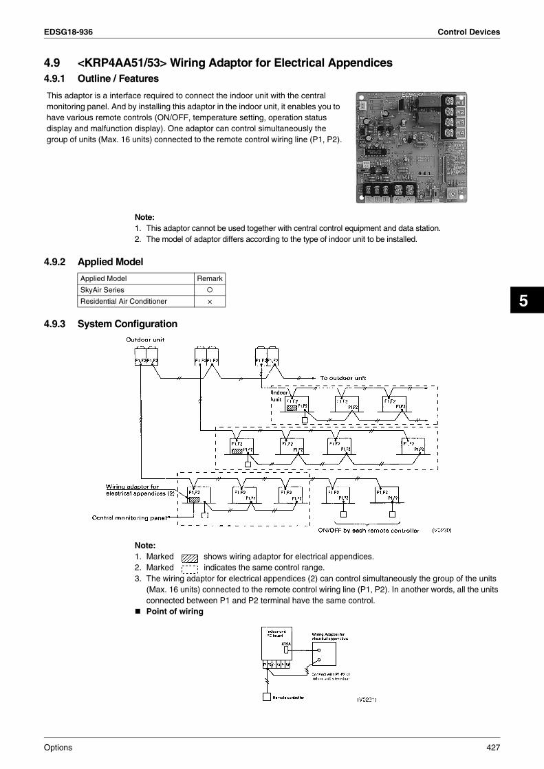
EDSG18-936 Control Devices
5
4.9 <KRP4AA51/53> Wiring Adaptor for Electrical Appendices4.9.1 Outline / Features
Note:1. This adaptor cannot be used together with central control equipment and data station.2. The model of adaptor differs according to the type of indoor unit to be installed.
4.9.2 Applied Model
4.9.3 System Configuration
Note:1. Marked shows wiring adaptor for electrical appendices.2. Marked indicates the same control range.3. The wiring adaptor for electrical appendices (2) can control simultaneously the group of the units
(Max. 16 units) connected to the remote control wiring line (P1, P2). In another words, all the units connected between P1 and P2 terminal have the same control.Point of wiring
This adaptor is a interface required to connect the indoor unit with the central monitoring panel. And by installing this adaptor in the indoor unit, it enables you to have various remote controls (ON/OFF, temperature setting, operation status display and malfunction display). One adaptor can control simultaneously the group of units (Max. 16 units) connected to the remote control wiring line (P1, P2).
Applied Model Remark
SkyAir Series
Residential Air Conditioner ×
Options 427

Control Devices EDSG18-936
4.9.4 Names and Functions of Operating Part
Note:1. This is valid only for the indoor unit, which has a temperature setting function.2. Terminal No. X18A is for the indoor unit of VRV system. For SkyAir series and other air-conditioner,
connect to the relevant terminal for each units.
4.9.5 Input/Output for External Control1. Depending on whether [voltage input] or [non voltage input], connect the wiring as shown below.
Input with Voltage.Set the Voltage/Non voltage changeover switch (SS1) to VOLT.
Input with No Voltage.Set the Voltage/Non voltage changeover switch (SS1) to NON VOLT.
2. Display Signal Retrieval (Output)The normal operation output terminals (W1, W2) and error output terminals (W3, W4) are non-voltage output contacts. (Permissive current is 10mA~3A per contact.)
Output is as given below.
OutputBoth Ry1 and Ry2 is OFF. Only Ry1 is ON. Only Ry2 is ON.
System
Group control OFF All normal operation At least one unit is stopped due to error or transmission error between the adaptor and the indoor unit.
428 Options

EDSG18-936 Control Devices
5
3. Temperature Setting Input
Temperature setting corresponds to resistance values in the range of 0 to 135Ω.Their relationship is as shown below.
Relation between the setting temperature and the resistance are as follows.
Note:The value of resistance includes the resistance of wiring.The setting temperature is limited within the setting range of indoor unit. If you set the temperature outside of the range by the adaptor, it controls at the nearest setting range.
Setting of Control Mode Selector Switch (RS1)
Note:1. When constant input is used for input B at position 7~A, the system is shut-down forcibly (Ignored input
A). Constant input cannot be used for input B at position B.2. Refer to the followings for the outline of above functions.
Setting temperature (°C)
16 17 18 19 20 21 22 23 24 25 26 27 28 29 30 31 32
Resistance (Ω)0.0~
3.4
5.0~
11.6
13.8~
20.0
22.4~
28.4
31.0~
36.4
39.4~
44.8
48.2~
52.8
56.6~
61.2
65.2~
69.4
73.8~
77.8
82.4~
85.8
91.0~
94.0
99.4~
102.2
108.6~
110.4
117.2~
119.2
125.8~
127.4
134.2~
140.0
Position FunctionsDescription of Operation by Input Mode A and B
Input A (Between B1~Bc) Input B (Between B2~Bc)
0 Input Ignored — —
1 Remote Control Rejection Start at ON, and stop at OFF
Stop at ON(remote control rejection),Input A acceptance at OFF
2 Central Priority Start at ON (remote control acceptance), stop at OFF (remote control rejection)
3 Remote Control Acceptance/Rejection
The same as position 1(Only stop is accepted by remote controller)
4 Remote Control Acceptance/Rejection, OFF
Start at ON (remote control acceptance),stop at OFF (remote control rejection)
5 Remote Control Rejection Start/Stop (Repeats)
6 Last Command Priority The same as position 5(remote control acceptance all the time)
Stop at ON remote control acceptance),start at OFF (remote control rejection)
7 Remote Control Rejection Start at ON Stop at ON.
8 Last Command Priority Start at ON(remote control acceptance)
Stop at ON(remote control rejection)
9 Remote Control OFF Acceptance The same as position 7(Only stop is accepted by remote controller) The same as position 7
A Remote Control Acceptance/Rejection, OFF
Start at ON(remote control acceptance)
Stop at ON(remote control rejection)
B Last Command Priority The same as position 7(remote control acceptance all the time) The same as position 7
C Position 5 + Energy Saving ControlThe same as position 5
Forced thermostat OFF at ON
D Position 5 + Temperature Set-Back Setting temperature shift command at ON
E Position 6 + Energy Saving ControlThe same as position 6
Forced thermostat OFF at ON
F Position 6 + Temperature Set-Back Setting temperature shift command at ON
Options 429

Control Devices EDSG18-936
Description of Functions (Outline)
<Example when the control mode selector switch is set at position 6>
The following is the time chart for the command by remote controller and the indoor unit against input signal.
1. Remote Control Rejection ................................ For when you want to turn ON/OFF only by central remote controller. (ON/OFF cannot be controlled by remote controller for indoor unit.)
2. Remote controller OFF Only Accepted ...... For when you want to turn ON only by the central remote controller, and turn OFF only by remote controller for indoor unit.
3. Central Priority ............................................... For when you want to turn ON only by the central remote controller, and during the set time, turn ON/OFF freely by remote controller for indoor unit.
4. Individual Priority (Last command priority) ... For when you want to turn ON/OFF by both central remote controller and remote controller for indoor unit.
5. Remote Controller Permission Timer ........... For when you want to turn ON/OFF by remote controller for indoor unit during set time, and you want to start the operation by remote controller for indoor unit at the programmed time of system start.
430 Options

EDSG18-936 Control Devices
5
4.9.6 Instruction for InstallationCeiling Mounted Cassette Type (600×600) Ceiling Mounted Cassette Type (950×950)
Note:Installation box for adaptor PCB is required to install the adaptor.
(R4931)
Ceiling Mounted Built-In Type
FFQ
(KRP4A53)
PCB support
Installation box for adaptor PCB
Adaptor
Lid of installation boxKRP1B101 (Option accessory)
(V3126)
KRP1B101 (Option accessory)
Note:Installation box for adaptor PCB isrequired to install the adaptor.
(Fit the edge of the adaptor PCB into the grooves on the adaptor box.)
AdaptorKRP4A(A)53
Adaptor fixing box
KRP1B98 (Optional accessory)
Groove
Options 431

Control Devices EDSG18-936
4.10 <KRP1BA54/57> Adaptor for Wiring
C:1PA60037E
(950×950)<< Ceiling-mounted cassette type >>
(600×600)
( )
A
NOTE:NOTE: Installation box for adaptor PCB is required to install the adaptor.Installation box for adaptor PCB is required to install the adaptor.
432 Options

EDSG18-936 Control Devices
5
4.11 <KRP1BA101> Installation Box for Adaptor PCB
C : 1P107687-1C
<IN CASE OF FFQ TYPE>
Notes
Accessories
Method of attaching the adaptor
Applicable adaptor
Refer to the installation manuasl attached to the indoor unit and adaptor.
One kit is required for each adaptor.
Quantity
(IN CASE OF FFQ TYPE)
Shape
Name
Attach the adaptor in the Installation box(PCB supports are accessories of adaptor.)
Adaptor for wiring
Attach the adaptor
Wiring adaptor forelectrical appendices(2)
Detach the aluminum tape of the Installation box
Low voltage wires and high voltage wires should be kept space at least 50mm from each other.Connect wires with the adaptor before attaching to the Installation box
KRP2A52,KRP2A62,KRP4A(A)53,DTA104A52Adaptor : KRP1B(A)57
Installation box
1
Adaptor
x1
Check the following accessories are included in this kit.
voltage field wiresHole for high
Lid of
(Signal line)
2
installation box
voltage wiresHole for low
x1
Adaptor PCB
BA
A
B
A
KRP4A(A)53
KRP1B(A)57
B
3
Kit name
A
1
Clamp
x3
by the PCB supports.
B
1
--- Detach the aluminume tapes B.--- Detach the aluminume tapes A.
to insert the PCB supports.
4
Screws
Installation box
x3
PCB supports(Accessories of Adaptor)
1 .
5
Cord sticker
x3
1
Kit name
KRP1BA101
6
manualInstallation
( This manual )
English x1Japanese x1
FFQ25 • 35 • 50 • 60BV1B9
7
Indoor unit
Screws
x2
Options 433

Control Devices EDSG18-936
C : 1P107687-1C
Method of wiring processing
Attach the Installation box
Attach the Lid of installation boxIf two adaptors are installed, the second adaptor is attached to side of first one.
Attach the Installation box
Attach the Lid of installation box
as shown in the below drawing.After connecting wires with the control box, clamp wires by using the cord stickers
Connect wires with control box. (Refer to the installation manual attached to the adaptor.)
Cord sticker
1 into the Lid of installation box
Lid ofi nstallation box
2
5
to indoor unit with two screws.
Installation box
for first PCBLid of installation box
2
1
2
Put the Installation boxinto the Lid of installation box
with the screw.
5
2
and the clamps
screw
Clamp
1
3
4
3
screws
2
for second PCBLid of installation box
4
2
434 Options

EDSG18-936 Control Devices
5
4.12 <KRCS01-1B> Remote Sensor
Mounting
Insert a flat blade screw driver into the sensor box concavepart (2 locations)and remove the cover pushig up the nail to the cover of the sensor box.
Components
<Cautions>Do not push the nail powerfully with a narrow flat blade screw driver,because you may break off the nail.
about 6mm width flat blade screw driver
1 Piece
2
2 PiecesPieces
shape
Installationmanual
(this drawing)
3 where it is not influenced by other heat sources.
Check the following components.
where it is not exposed to the direct sunlight.2
Sensor boxmounting screws
(M4X16)Designation
1 Piece
Note 1) If you are unsure if this kit can be used for your indoor unit, check if the type of the thermistor
(for detection of inlet air temperature) is as same as the type in this kit (ST8601).
The shape of the thermistor for detection of the indoor unit inlet air temperature is shown below.
1 sheet
1 where the average temperature of an air conditioned room can be detected.
Extension cable
(2-core, 12m)
5 whera it is not exposed to the outdoor air infiltrated into the room by opening the door.
2 Pieces
where it is not exposed to the direct discharge air from the air conditioner.4
Clamps
1) Selecting the mounting location
The thermistor for temperature detection is incorporated into the remote sensor. Select the mounting
location taking the following cautions into account.
2) Mounting
Remote sensor
(sensor box)
Remove the cover of the sensor box.
1
ST8601
Options 435

Control Devices EDSG18-936
Knockout hole for cable
(70)
Sensor box
Through hole
Clamp(knot)
Extension cable
Air holes
Released paper
42 (120
)
Extension cable
Heat insulating material
Mounting screws
Sheathed part
Metal plate(for single unit without hole)
Clamp holes
Clamp(knot)
21
Fasten the terminals with care to prevent the wires from touching each other.
Sensor box
Give caution when wiring so that the air holes will not be blocked.
When mounting on the wall
32
Mounting frame whichmatches with the switch box
Pass the extension cable through the switch box cable hole and carry out the wiring.
<Cautions>
Switch box(for single unit)
To avoid tensile force on the terminals, pass the attached clamp through the holes shown in the belowright figure and tighten the extension cable with the attached clamp at the sheathed part. (The knot mustcome to the box inside.)
Mounting screws
Sheathed part
Sensor box
For M3Round crimp terminal
Wall surface mounting holes(unit Fmm)
Holes to be tapped in themetal plate on site (unit: mm)
2-M4 42
Screw the sensor box securely to the wall surface with screws M4X16(2 places).If the sensor box cannot be screwed to wall surface, tear off the released paper and mount it on the wall surface
Sensor box cover
2
1
(to be sourced locally)
(to be sourced locally)
2-M4
Heat insulating material
32
45
When the extension cable is longer than necessary, cut it to the apporopriate length, peel the insulation,attach the round crimp terminal for M3 (to be sourced locally) and carry out the wiring. The length ofinsulation to be peeled off is as shown.(Work carefully so that the connector side may not be cut.)
Tap M4 screw holes in the metal plate (to be sourced locally) as shown in the right drawing and mount the switch box on the metal plate.
(to be sourced locally)
Sensor box cover
Break open the knockout hole in the sensor box with a nipper or a similar tool. Pass the extension wiresthrough the hole and fasten the wires to the terminals with screws.
For embedded wiring
Pass the attached clamp though the clamp holes and tighten the extension cable at the sheathed part as shown in the upper right drawing.
Sensor box
436 Options

EDSG18-936 Control Devices
5
Screwed terminal connection
Extension cable
Connector connection
1
2
3. Fit the sensor box cover into the sensor box.
Indoor unit
2) When wiring the extension cable, do not pass where the extension cable may be affected by the power line or noise.
1. When wiring to the indoor unit PCB, remove the existing thermistor (for detection of inlet air temperature) and then connect the extension cable.
<Procedure>
4) Do not splice wires.
1) Make sure to turn off the power supply before starting the wiring work and do not turn on until all the work is completed. Read also the installation manual and the wiring diagram of the indoor unit when carrying out the work.
Extension cable
6)Lay and clamp the extension cable inside the indoor unit switch box just like the low voltage line(cord for remote controller). And do not pass where the extension cable inside the indoor unit switch box may be affected by the power line(cord for the indoor unit and the other electric line).
3) Make sure to securely connect the connectors. Defective connection may result in incorrect detection of room temperature or malfunction.
Operation test after mounting the sensor
Remove
Connect the extension cable connector side to the indoor unit PCB (printed circuit board)
For connection to the indoor unit, follow the procedure shown below.
5) Since the connector marking of the thermistor for detection of inlet air temperature differ depending on the indoor unit type, make sure to check the indoor unit wiring diagram and follow it correctly.
Connect
Conduct cooling and heating operation test after the sensor is mounted and the wiring is completed.
Wiring method
Caution!
Indoor unitPrinted circuit board (PCB)
2. Lay and clamp the extension cable inside the indoor unit switch box just like the existing thermistor. Provide protection of the existing cable for thermistor without affecting other components.
<For SkyAir and VRV>
Existing thermistor or humidity sensor
C : 3K019189B
Options 437

Control Devices EDSG18-936
4.13 <BRC1C61> Wired Remote Controller for SkyAir4.13.1 Features and Functions
<BRC1C61>
Large liquid crystal screen displays complete operating status.Digital display lets you set temperature in a unit of 1°C.Possible to make the individual setting such as not only the combined operation with the total heat exchanger HRV but also the single operation, the fresh-up operation, and the filter sign, without HRV's exclusive remote controller.Lets you individually program by timer the respective times for operation start and stop within a maximum of 72 hours.Equipped with a thermostat sensor in the remote controller that makes possible more comfortable room temperature control.Monitors room temperature and preset temperature by microcomputer, and can switch cool/heat operation mode automatically.Enables you to switch cool / heat / fan operation mode with the indoor remote controller of your choice without using the cool / heat selector.Constantly monitors malfunctions in the system for 40 items, and is equipped with a “self-diagnosis function” that lets you know by message immediately when a malfunction occurs.Lets you carry out various field settings by remote controller.
TEST
Chr
hrTEST
NOTAVAILABLE
L H
2
1011
3
145
6
7
8
14
1516 17 18
19
20
21
22
12
9
13
3PA59583-16Z-1
438 Options

EDSG18-936 Control Devices
5
1
ON/OFF BUTTONPress the button and the system will start. Press the button again and the system will stop.
2OPERATION LAMP (RED)The lamp lights up during operation.
3
DISPLAY “ ” (UNDER CENTRAL-IZED CONTROL)When this display shows, the system is UNDER CENTRALIZED CONTROL.
4
DISPLAY “ ” “ ” “ ” “ ” (VENTILATION/AIR CLEANING)This display shows that the total heat exchange and the air cleaning unit are in operation (These are optional accessories).
5
DISPLAY “ ” “ ” “ ” “ ” “ ” (OPERATION MODE)This display shows the current OPERATION MODE. For cooling only type, “ ” (Auto) and “ ” (Heating) are not installed.
6
DISPLAY “ TEST” (INSPECTION/TEST OPERATION)When the INSPECTION/TEST OPERATION BUTTON is pressed, the display shows the system mode is in.
7DISPLAY “ ” (PROGRAMMED TIME)
This display shows the PROGRAMMED TIME of the system start or stop.
8DISPLAY “ ” (SET TEMPERATURE)This display shows the set temperature.
9DISPLAY “ ” (FAN SPEED)This display shows the set fan speed.
10DISPLAY “ ” (AIR FLOW FLAP)
11DISPLAY “ ” (TIME TO CLEAN AIR FIL-TER)
12DISPLAY “ ” (DEFROST)
13
NON-FUNCTIONING DISPLAYIf that particular function is not available, press-ing the button may display the words “NOT AVAILABLE” for a few seconds.When running multiple units simultaneouslyThe “NOT AVAILABLE” message will only be appear if none of the indoor units is equipped with the function. If even one unit is equipped with the function, the display will not appear.
hr
hr
C
14TIMER MODE START/STOP BUTTON
15TIMER ON/OFF BUTTON
16INSPECTION/TEST OPERATION BUTTONThis button is used only by qualified service persons for maintenance purposes.
17PROGRAMMING TIME BUTTONUse this button for programming “START and/or STOP” time.
18TEMPERATURE SETTING BUTTONUse this button for SETTING TEMPERATURE.
19FILTER SIGN RESET BUTTON
20FAN SPEED CONTROL BUTTONPress this button to select the fan speed, HIGH or LOW, of your choice.
21OPERATION MODE SELECTOR BUTTONPress this button to select OPERATION MODE.
22AIR FLOW DIRECTION ADJUST BUTTON
NOTE• For the sake of explanation, all indications are
shown on the display in Figure 1 contrary to actual running situations.
3PA59583-16Z-2
Options 439

Control Devices EDSG18-936
Example of Control by Remote Controller
Note:1. If the system structure displaces the SkyAir's wired remote controller with a wireless remote controller,
the same control can be carried out.2. Impossible to structure with twin wireless remote controllers in case of the control adopting double
remote controllers. Be sure to use a wired remote controller for the one of the two controllers.
Double Remote ControllersOne indoor unit is controlled by double remote controllers from two separate locationsThis is a convenient system, when you want to operate an indoor unit in a living room from a porch, for example, or finely operate an indoor unit from a local or remote location. (The same applies to other types of indoor units.)
Operation control mode of the indoor unit has last command priority.Remove the front panel of the remote controller and set the MAIN/SUB changeover switch on the PC board to “MAIN” for the main remote controller, and to “SUB” for the sub remote controller.
Remote control (Fundamental use)The most fundamental use which connects one indoor unit with one remote controller.
Control by double remote controllersThis is a convenient system, when you want to operate an indoor unit in a living room from a porch, for example, or finely operate an indoor unit from a local or remote location. (The same applies to other types of indoor units.)
Group ControlSimultaneous control of up to 16 units with a one remote controller
Remote ControlThe remote control wiring can be extended up to 500m. Accordingly, it is easy to concentrate the plural remote controller of indoor units installed in a room widely spread into one position.
Combined controlSimultaneous control with a total heat exchanger HRV is possible through the indoor unit linkage.
440 Options

EDSG18-936 Control Devices
5
4.13.2 Example of System
Group ControlSimultaneous control of up to 16 units with a one remote controllerThis is a convenient system, when you want to simultaneously control several indoor units on the same settings for air conditioning a space with wide and single floor.
Wiring to a remote controller for group control has no polarity. So, P1 and P2 can be exchanged.All indoor units within the group have the same setting, and each indoor unit is controlled individually by its own built-in thermostat.Because the automatic address system is used, the address does not require the setting by a remote controller for group control.
Combined ControlSimultaneous control between HRV and SkyAir's indoor unit.This is a convenient system when the simultaneous control of SkyAir indoor unit with a total heat exchanger HRV is required.
Since the remote controller's wiring doesn't have polarity, opposite positioning between P1 and P2 is allowed.
One remote controller can conduct the simultaneous control up to 16 units (SkyAir indoor units + HRV = 16 units)
Options 441

Control Devices EDSG18-936
4.13.3 Installation
Switch Box
(Field supplied parts)
MachineScrews(M4 x 16)
1.Remove the upper part of remote controller.Insert minus screwdriver into the slots in the lower part ofremote controller (2 places), and remove the upper part ofremote controller.
The PC board is mounted in theupper part of remote controller. Becareful not to damage the boardwith the minus screwdriver.
2.Fasten the remote controller.For exposed mounting, fasten withthe included wood screws (2).
For flush-mounting, fasten withthe included machine screws (2).
For the field supplied switch box, use optional accessoriesKJB111A or KJB211A.
NOTEChoose the flattest place possible for the mounting sur-face. Be careful not to distort the shape of the lower part ofremote controller by over-tightening the mounting screws.
Upper Part ofRemote Controller
Lower Part ofRemote ControllerMinus screwdriver
Insert the minusscrewdriver andtwist lightly to remove.
Wood Screws(φ3.5 x 16)
442 Options

EDSG18-936 Control Devices
5
Lower part ofremote controller
Upper Part ofRemote controller
PC Board
Indoor UnitP1, P2
Indoor UnitP1, P2
(Wired from the top)(Wired from the rear)
Notch the part for the wiring topass through with nippers, etc.Ground the shielded
part on the indoorunit side. (NOTE.2)
PC BoardNOTE) 1.Peel the shield and sheath for
the part that is to pass through the inside of the remote control- ler case, as shown in the figure below.
2. Shield wire (2 wire) can beused for remote controllerwiring, but it must confirm toEMC (Electromagnetic Compat-ibility) (European Directive).
3.Wire the indoor unit.Connect the terminals on top of the upper part ofremote controller (P1, P2), and the terminals of theindoor unit (P1, P2). (P1 and P2 do not have polarity.)
NOTEWhen wiring, run the wiringaway the power supply wiring inorder to avoid receiving electricnoise (external noise).
4.Reattach the upper part of remote controller.Be careful not to pinch the wiring when attaching.
NOTE1.The switch box and wiring for connection are not included.2.Do not directly touch the PC board with your hand.
If controlling one indoor unit with two remotecontrollers
Change the MAIN/SUB changeover switch setting asdescribed below.
Set one remote controller to“main,” and the other to “sub.”
NOTEIf controlling with one remote controller, be sure to set itto “main.”Set the remote controller before turning power supply on.
“ ” is displayed for about one minute when the power supply is turned on,and the remote controller cannot be operated in some cases.
Wiring SpecificationsSheathed vinyl code or cable(2 wire) (NOTE.2)
0.75 – 1.25 mm2
Wiring Type
Size
Peel the shieldand sheath.
S
M
S
M
SubRemoteController
Main RemoteController(Factory Set)
PC Board
First, begin fitting fromthe clips at the bottom.
Options 443
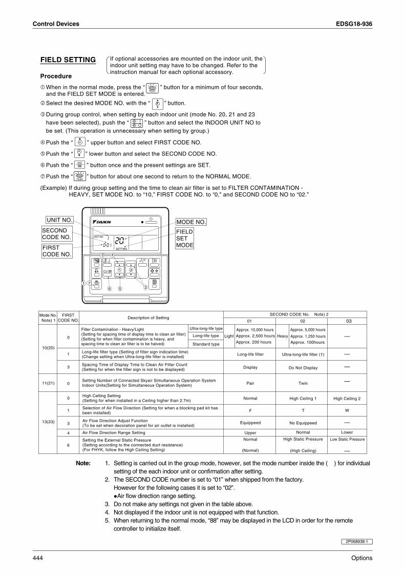
Control Devices EDSG18-936
Note: 1. Setting is carried out in the group mode, however, set the mode number inside the ( ) for individualsetting of the each indoor unit or confirmation after setting.
2. The SECOND CODE number is set to “01” when shipped from the factory.However for the following cases it is set to “02”.Air flow direction range setting.
3. Do not make any settings not given in the table above.4. Not displayed if the indoor unit is not equipped with that function.5. When returning to the normal mode, “88” may be displayed in the LCD in order for the remote
controller to initialize itself.
FIELD SETTING If optional accessories are mounted on the indoor unit, theindoor unit setting may have to be changed. Refer to theinstruction manual for each optional accessory.
Procedure
When in the normal mode, press the “ ” button for a minimum of four seconds,and the FIELD SET MODE is entered.
TEST
TEST
Select the desired MODE NO. with the “ ” button.
During group control, when setting by each indoor unit (mode No. 20, 21 and 23have been selected), push the “ ” button and select the INDOOR UNIT NO tobe set. (This operation is unnecessary when setting by group.)
Push the “ ” upper button and select FIRST CODE NO.
Push the “ ” lower button and select the SECOND CODE NO.
Push the “ ” button once and the present settings are SET.
Push the “ ” button for about one second to return to the NORMAL MODE.
(Example) If during group setting and the time to clean air filter is set to FILTER CONTAMINATION - HEAVY, SET MODE NO. to “10,” FIRST CODE NO. to “0,” and SECOND CODE NO to “02.”
Mode No.Note) 1
FIRSTCODE NO.
Description of SettingSECOND CODE No. Note) 2
01
Ultra-long-life type
Long-life type
Standard type
Long-life filter
Light Heavy0
Long-life filter type (Setting of filter sign indication time)(Change setting when Ultra-long-life filter is installed)
Approx. 10,000 hours
Approx. 2,500 hours
Approx. 200 hours
Approx. 5,000 hours
Approx. 1,250 hours
Approx. 100hours
02
Setting Number of Connected Skyair Simultaneous Operation System Indoor Units(Setting for Simultaneous Operation System)
Spacing Time of Display Time to Clean Air Filter Count(Setting for when the filter sign is not to be displayed)
High Celling Setting(Setting for when installed in a Ceiling higher than 2.7m)
Selection of Air Flow Direction (Setting for when a blocking pad kit has been installed)
Air Flow Direction Adjust Function(To be set when decoration panel for air outlet is installed)
Air Flow Direction Range Setting
Setting the External Static Pressure(Setting according to the connected duct resistance)(For FHYK, follow the High Ceiling Setting)
Display
Pair
Normal
F
Equippeed
Upper
Normal
(Normal)
Ultra-long-life filter (1)
Do Not Display
Twin
High Ceiling 1
T
No Equippeed
Normal
High Static Pressure
(High Ceiling)
Low Static Pressure
Lower
High Ceiling 2
W
03
1
3
0
0
1
3
4
6
10(20)
11(21)
13(23)
SETTING
TEST
UNIT NO.
3 4
5671
2
FIELDSETMODE
UNIT NO.
.SECONDCODE NO.
.
MODE NO.
FIRSTCODE NO.
.
—
—
—
—
—
—
Filter Contamination - Heavy/Light(Setting for spacing time of display time to clean air filter)(Setting for when filter contamination is heavy, andspacing time to clean air filter is to be halved)
2P068938-1
444 Options
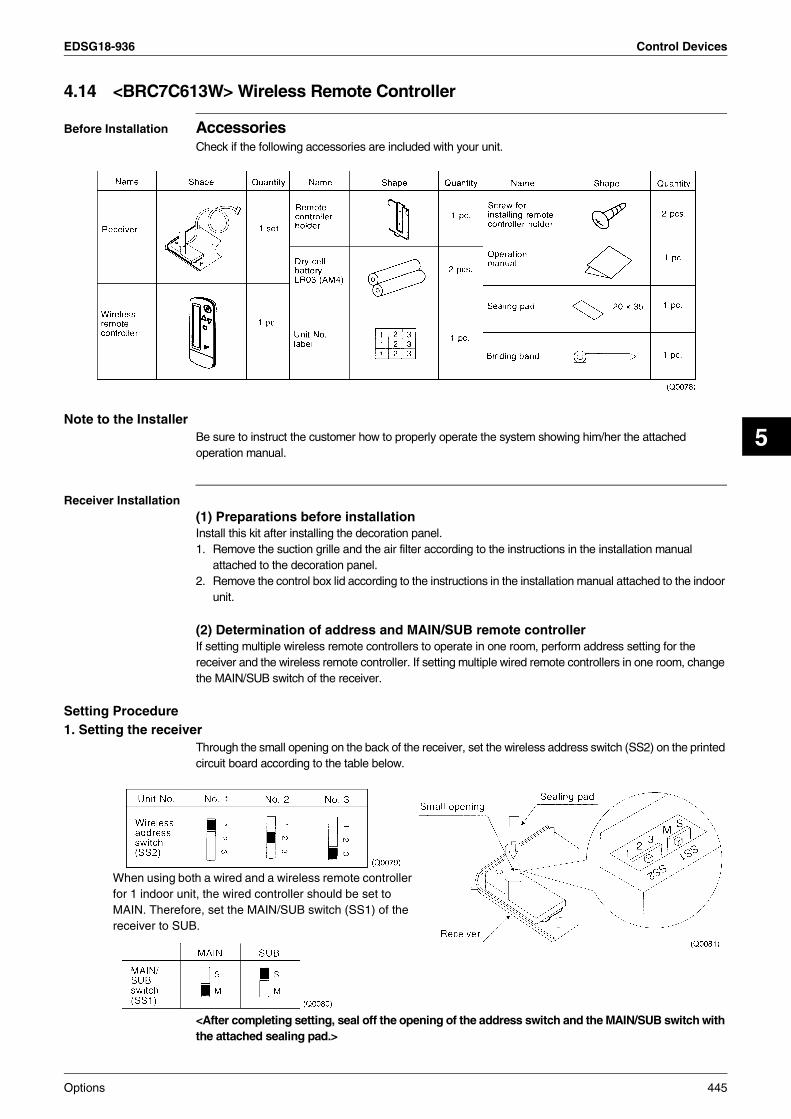
EDSG18-936 Control Devices
5
4.14 <BRC7C613W> Wireless Remote Controller
Before Installation AccessoriesCheck if the following accessories are included with your unit.
Note to the InstallerBe sure to instruct the customer how to properly operate the system showing him/her the attached operation manual.
Receiver Installation(1) Preparations before installationInstall this kit after installing the decoration panel.1. Remove the suction grille and the air filter according to the instructions in the installation manual
attached to the decoration panel.2. Remove the control box lid according to the instructions in the installation manual attached to the indoor
unit.
(2) Determination of address and MAIN/SUB remote controllerIf setting multiple wireless remote controllers to operate in one room, perform address setting for the receiver and the wireless remote controller. If setting multiple wired remote controllers in one room, change the MAIN/SUB switch of the receiver.
Setting Procedure1. Setting the receiver
Through the small opening on the back of the receiver, set the wireless address switch (SS2) on the printed circuit board according to the table below.
<After completing setting, seal off the opening of the address switch and the MAIN/SUB switch with the attached sealing pad.>
When using both a wired and a wireless remote controller for 1 indoor unit, the wired controller should be set to MAIN. Therefore, set the MAIN/SUB switch (SS1) of the receiver to SUB.
Options 445

Control Devices EDSG18-936
2. Setting the address of wireless remote controller (It is factory set to “1”)<Setting from the remote controller> Hold down the button and the button for at least 4 seconds to get the Field Set
mode. (Indicated in the display area in the figure at right). Press the button and select a multiple setting (A/b). Each time the button is pressed the
display switches between “A” and “b”. Press the “ ” button and “ ” button to set the address.
Address can be set from 1 to 6, but set it to 1 ~ 3 and to same address as the receiver. (The receiver does not work with address 4 ~ 6.)
Press the button to enter the setting. Hold down the button for at least 1 second to quit the Field Set mode and return to the
normal display.
Multiple setting A/bWhen the indoor unit is being operating by outside control (central remote controller, etc.), it sometimes does not respond to ON/OFF and temperature setting commands from this remote controller. Check what setting the customer wants and make the multiple setting as shown below.
Remote controller Indoor unit
Multiple setting Remote controller display To control other air conditions and units For other than on left
A:Standard All items displayed.
Commands other than ON/OFF and temperature setting accepted. (1 LONG BEEP or 3 SHORT BEEPS emitted)
b:Multi System Operations remain displayed shortly after execution. All commands accepted (2 SHORT BEEPS)
446 Options
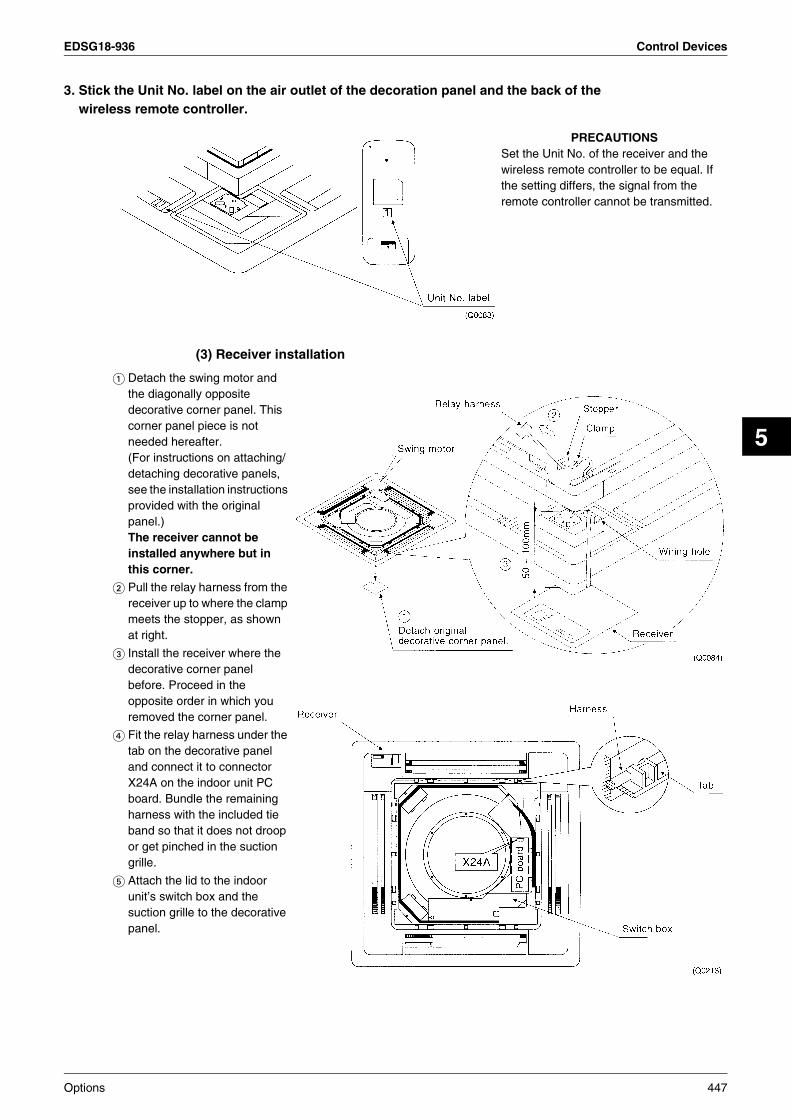
EDSG18-936 Control Devices
5
3. Stick the Unit No. label on the air outlet of the decoration panel and the back of the wireless remote controller.
(3) Receiver installation
PRECAUTIONSSet the Unit No. of the receiver and the wireless remote controller to be equal. If the setting differs, the signal from the remote controller cannot be transmitted.
Detach the swing motor and the diagonally opposite decorative corner panel. This corner panel piece is not needed hereafter.(For instructions on attaching/detaching decorative panels, see the installation instructions provided with the original panel.)The receiver cannot be installed anywhere but in this corner.
Pull the relay harness from the receiver up to where the clamp meets the stopper, as shown at right.
Install the receiver where the decorative corner panel before. Proceed in the opposite order in which you removed the corner panel.
Fit the relay harness under the tab on the decorative panel and connect it to connector X24A on the indoor unit PC board. Bundle the remaining harness with the included tie band so that it does not droop or get pinched in the suction grille.
Attach the lid to the indoor unit’s switch box and the suction grille to the decorative panel.
Options 447

Control Devices EDSG18-936
Note:The SECOND CODE NO. is factory set to “01”. However, for the following cases it is set to “02”.
Air Flow Direction Range SettingDo not use any settings not listed in the table.For group control with a wireless remote controller, initial settings for all the indoor units of the group are equal. (For group control, refer to the installation manual attached to the indoor unit for group control.)
MODE NO.
FIRST CODE NO. DESCRIPTION OF SETTING
SECOND CODE NO. NOTE)
01 02 03
10
0
Filter Contamination-Heavy/Light (Setting for spacing time of display time to clean air filter) (Setting for when filter contamination is heavy, and spacing time of display time to clean air filter is to be halved)
Long Life Filter Light Approx.
2,500 hrs. Heavy Approx. 1,250 hrs. —
3Spacing time of display time to clean air filter count (Setting for when the filter sign is not to be displayed)
Display Do not display —
11(SkyAir system)
0 Setting the number of connected simultaneous operation system indoor units. Pair Twin Triple
12(VRV
system)
1 ON/OFF input from outside (Set to enable starting/stopping from remote.) Forced OFF input ON/OFF —
2 Thermostat differential changeover (Set when using remote controller thermostat sensor.) 1°C 0.5 °C —
13
0 High ceiling setting (Setting for when installed in a ceiling higher than 2.7m) Normal High Ceiling 1 High Ceiling 2
1 Selection of Air Flow Direction (Setting for when a blocking pad kit has been installed) F T W
4 Air Flow Direction Range Setting Upper Normal Lower
448 Options
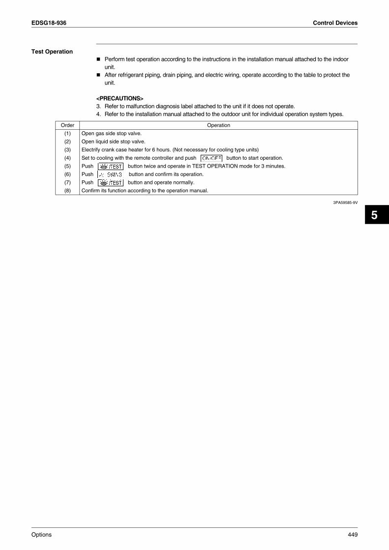
EDSG18-936 Control Devices
5
Test OperationPerform test operation according to the instructions in the installation manual attached to the indoor unit.After refrigerant piping, drain piping, and electric wiring, operate according to the table to protect the unit.
<PRECAUTIONS>3. Refer to malfunction diagnosis label attached to the unit if it does not operate.4. Refer to the installation manual attached to the outdoor unit for individual operation system types.
3PA59585-9V
Order Operation
(1) Open gas side stop valve.
(2) Open liquid side stop valve.
(3) Electrify crank case heater for 6 hours. (Not necessary for cooling type units)
(4) Set to cooling with the remote controller and push button to start operation.
(5) Push button twice and operate in TEST OPERATION mode for 3 minutes.
(6) Push button and confirm its operation.
(7) Push button and operate normally.
(8) Confirm its function according to the operation manual.
Options 449

Control Devices EDSG18-936
4.15 <BRC7E531W> Wireless Remote Controller
Names and Function
Explanation of Receiver
Name of OptionModel Series
FFQ-B
Remote Controller C / O BRC7E531W
8
10
13
11
12
15
14
16
17
9
1
3
4
6
2
5
7
DOWN
FAN
UP
ON OFF
MH L
C
hr.
hr.
TESTMODE
TIMER
RESERVE CANCEL
DOWNUP
TEST
SWING
FAN
TIMETEMP
ON OFF
MH L
C
hr.
hr.
TEST
3PA63363-21T-1
FFQ
3P107422-1F
21 20 22 23
19
18
450 Options
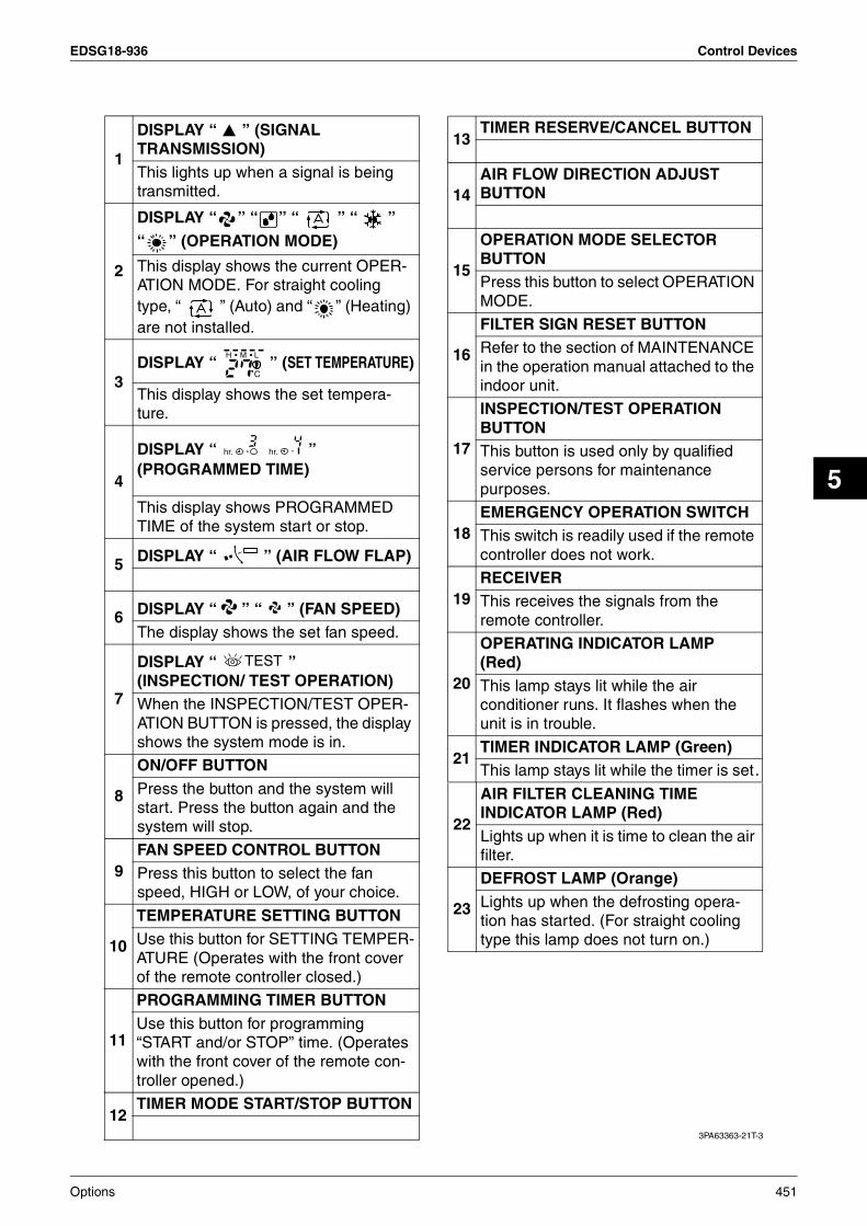
EDSG18-936 Control Devices
5
1
DISPLAY “ ” (SIGNAL TRANSMISSION)This lights up when a signal is being transmitted.
2
DISPLAY “ ” “ ” “ ” “ ” “ ” (OPERATION MODE)
This display shows the current OPER-ATION MODE. For straight cooling type, “ ” (Auto) and “ ” (Heating) are not installed.
3DISPLAY “ ” (SET TEMPERATURE)
This display shows the set tempera-ture.
4
DISPLAY “ ” (PROGRAMMED TIME)
This display shows PROGRAMMED TIME of the system start or stop.
5 DISPLAY “ ” (AIR FLOW FLAP)
6 DISPLAY “ ” “ ” (FAN SPEED)The display shows the set fan speed.
7
DISPLAY “ ” (INSPECTION/ TEST OPERATION)When the INSPECTION/TEST OPER-ATION BUTTON is pressed, the display shows the system mode is in.
8
ON/OFF BUTTONPress the button and the system will start. Press the button again and the system will stop.
9FAN SPEED CONTROL BUTTONPress this button to select the fan speed, HIGH or LOW, of your choice.
MH L
C
hr. hr.
TEST
10
TEMPERATURE SETTING BUTTONUse this button for SETTING TEMPER-ATURE (Operates with the front cover of the remote controller closed.)
11
PROGRAMMING TIMER BUTTONUse this button for programming “START and/or STOP” time. (Operates with the front cover of the remote con-troller opened.)
12TIMER MODE START/STOP BUTTON
13TIMER RESERVE/CANCEL BUTTON
14AIR FLOW DIRECTION ADJUST BUTTON
15
OPERATION MODE SELECTOR BUTTONPress this button to select OPERATION MODE.
16
FILTER SIGN RESET BUTTONRefer to the section of MAINTENANCE in the operation manual attached to the indoor unit.
17
INSPECTION/TEST OPERATION BUTTONThis button is used only by qualified service persons for maintenance purposes.
18EMERGENCY OPERATION SWITCHThis switch is readily used if the remote controller does not work.
19RECEIVERThis receives the signals from the remote controller.
20
OPERATING INDICATOR LAMP (Red)This lamp stays lit while the air conditioner runs. It flashes when the unit is in trouble.
21TIMER INDICATOR LAMP (Green)This lamp stays lit while the timer is set.
3PA63363-21T-3
22
AIR FILTER CLEANING TIME INDICATOR LAMP (Red)Lights up when it is time to clean the air filter.
23
DEFROST LAMP (Orange)Lights up when the defrosting opera-tion has started. (For straight cooling type this lamp does not turn on.)
Options 451
Warning Daikin Industries, Ltd.’s products are manufactured for export to numerous countries throughout the world. Daikin Industries, Ltd. does not have control over which products are exported to and used in a particular country. Prior to purchase, please therefore confirm with your local authorised importer, distributor and/or retailer whether this product conforms to the applicable standards, and is suitable for use, in the region where the product will be used. This statement does not purport to exclude, restrict or modify the application of any local legislation.
Ask a qualified installer or contractor to install this product. Do not try to install the product yourself. Improper installation can result in water or refrigerant leakage, electrical shock, fire or explosion.
Use only those parts and accessories supplied or specified by Daikin. Ask a qualified installer or contractor to install those parts and accessories. Use of unauthorised parts and accessories or improper installation of parts and accessories can result in water or refrigerant leakage, electrical shock, fire or explosion.
Read the User's Manual carefully before using this product. The User's Manual provides important safety instructions and warnings. Be sure to follow these instructions and warnings.
If you have any enquiries, please contact your local importer, distributor and/or retailer.
1. Air conditioners should not be installed in areas where corrosive gases, such as acid gas or alkaline gas, are produced.2. If the outdoor unit is to be installed close to the sea shore, direct exposure to the sea breeze should be avoided. If you need to install the outdoor unit close to the sea shore, contact your local distributor.
Cautions on product corrosion
JMI-0107 JQA-1452
Organization:DAIKIN INDUSTRIES, LTD.AIR CONDITIONING MANUFACTURING DIVISION
Scope of Registration:THE DESIGN/DEVELOPMENT AND MANUFACTURE OF COMMERCIAL AIR CONDITIONING, HEATING, COOLING, REFRIGERATING EQUIPMENT, COMMERCIAL HEATING EQUIPMENT, RESIDENTIAL AIR CONDITIONING EQUIPMENT, HEAT RECLAIM VENTILATION, AIR CLEANING EQUIPMENT, MARINE TYPE CONTAINER REFRIGERATION UNITS, COMPRESSORS AND VALVES.
Organization:DAIKIN INDUSTRIES(THAILAND) LTD.
Scope of Registration:THE DESIGN/DEVELOPMENTAND MANUFACTURE OF AIR CONDITIONERS AND THE COMPONENTS INCLUDING COMPRESSORS USED FOR THEM
All of the Daikin Group’s business facilities and subsidiaries in Japan are certified under the ISO 14001 international standard for environment management.
DealerHead Office:Umeda Center Bldg., 2-4-12, Nakazaki-Nishi,Kita-ku, Osaka, 530-8323 Japan
Tokyo Office:JR Shinagawa East Bldg., 2-18-1, Konan,Minato-ku, Tokyo, 108-0075 Japan
http://www.daikin.com/global_ac/
EDSG18-936Printed in Japan 08/2009 B AK
All rights reservedc
Specifications, designs and other content appearing in this brochure are current as of August 2009 but subject to change without notice.