Embed Size (px)
Citation preview

Aerospace Group Conveyance Systems Division Carter® Brand Ground Fueling Equipment
SM60600 October 1993 Applicable addition manuals: None
Maintenance Manual
Hydrant Couplers with Pressure Control To Mate Hydrants In Accordance With Bulletin API 1584 Model 60600 & 60600-2

SM60600 October 1993
- 2 -
TABLE OF CONTENTS
Page
1.0 Introduction.............................................................................................................................. 3 2.0 Equipment Description ............................................................................................................ 3 3.0 Table Of Options ..................................................................................................................... 3 4.0 Operation................................................................................................................................. 4 5.0 Safety Instructions - Periodic Inspections................................................................................ 6 6.0 Trouble Shooting And Minor Repair ........................................................................................ 9 7.0 Installation ............................................................................................................................. 14 8.0 Special Tools......................................................................................................................... 15 9.0 Disassembly .......................................................................................................................... 16 10.0 Inspection and Repair............................................................................................................ 20 11.0 Reassembly........................................................................................................................... 22 12.0 Testing................................................................................................................................... 31 13.0 Storage.................................................................................................................................. 33 14.0 Illustrated Parts Catalog ........................................................................................................ 34 15.0 Obsolete Parts Information.................................................................................................... 41 FIGURE 1A- Overall Coupler View.................................................................................................. 44 FIGURE 1B - Options L & M............................................................................................................ 45 FIGURE 1C - 41794 Handle Assembly ........................................................................................... 46 FIGURE 1D - 41795 Guard Assembly............................................................................................. 46 FIGURE 2A - Lower Half Coupler View ........................................................................................... 47 FIGURE 2B - Folding Handle .......................................................................................................... 48 FIGURE 3A - Pressure Control Elbow Assy .................................................................................... 49 FIGURE 3B - Pressure Relief Valve Assy ....................................................................................... 50 FIGURE 4A - Options F, G, H & J Female Half QD......................................................................... 51 FIGURE 4B - Option D Male Half Outlet..........................................................................................51 FIGURE 4C - Option K Quick Disconnect ....................................................................................... 52 FIGURE 5 - Collar Stop Lock Assy.................................................................................................. 53 FIGURE 6 - Collar Lock Assembly Instructions ............................................................................... 53 FIGURE 7A - Carriage Assy............................................................................................................ 54 FIGURE 7B - Carriage Assy Installation.......................................................................................... 55

SM60600 October 1993
- 3 -
1.0 INTRODUCTION
This manual furnishes instructions for the installation, operation, periodic inspection, trouble shooting and minor repair, as well as complete overhaul of Eaton’s Carter® Ground Fueling Models 60600 & 60600-2 Fuel pressure control couplers designed to mate adapters and hydrant valves built in accordance with API Bulletin1584.
Models 60600-1 and 60600-3 include the same features as Model 60600 with the addition of single and dual position excess flow control.
Maintenance and overhaul of repairable subassemblies, including all the various options are also included.
The latter section of this manual contains illustrated parts listing for all of the various sections and options of the unit. In addition, some information on obsolete parts and older units is included for reference.
2.0 EQUIPMENT DESCRIPTION
The standard Carter fuel pressure control couplers, Models 60600 & 60600-2, consist of three basic modules; a standard Model 61525 or 61525S, respectively, dry break coupler lower half, a fuel pressure control elbow assembly, Model 41806, and various female disconnects each with a different thread type and size. Other options are available as explained in the following Table 1.
The Model 60600 coupler is designed to mate with standard 4-inch adapters and hydrant valves that conform to API Bulletin 1584. Model 60600-2 is identical to Model 60600, except that the lower half utilizes the short stroke version of the 61525 lower half to mate with early Whittaker F368 hydrant valves that had a stroke of 1.75 inches (44.45 mm).
The outlet of the unit may be equipped with one of five female half quick disconnects. Four of the five types of disconnects are identical except for the female pipe thread size and type incorporated in the housing that mates with the hose fitting. The fifth disconnect utilizes an older design that has less swivel capability, but is still preferred by some customers. The table in paragraph 3.0 tabulates the various options available with the basic units.
The 61525 or 61525S lower half provides a quick means to connect to a hydrant or adapter with dry break capability. The coupler can not be accidentally opened unless it is connected to a valve; it can not be removed from that valve unless it is in the closed position.
The unit incorporates a pressure operated relief valve that is automatically opened by the coupler when the
coupler poppet is closed. This relief valve provides a vent to the downstream side of the main piston seat, relieving a hydraulic lock that would otherwise prevent coupler poppet closing. The spring loaded relief valve also relieves automatically whenever the differential pressure across the closed pressure control piston seat exceeds approximately 200 psi in the inlet to outlet direction.
The 41806 pressure control elbow assy is a pilot operated normally closed fuel pressure control and shutoff valve. Application of 25 psig air pressure (bias) greater than the desired fuel pressure through the air pressure connector overrides the pilot diaphragm spring and, opposed by remote sensed fuel pressure, holds the diaphragm in the positions required to maintain the desired control pressure in the main piston chamber to obtain the desired pressure at the remote sensed point throughout the ranges of all normal inlet pressures and fuel flow rates. Release of the air pressure, normally through a three-way deadman type valve, results in the spring force plus the fuel sense pressure causing the pilot diaphragm assembly to close thereby blocking off the bleed from the main piston. This, in turn, causes the main piston to close. The main piston also closes whenever the downstream flow passages are blocked, causing the fuel sense pressure transmitted back from the remote sensed location to rise above the preset limits.
A choice of four different orifices is available to allow the choice of opening times to be from 15 to 55 seconds. See paragraph 3.0 for more details on this feature.
3.0 TABLE OF OPTIONS
The basic unit, 60600 or 60600-2, is available with a variety of options to customize it to meet specific requirements as listed in Table 1 below. The various options, when compatible, may be combined and listed following the part number 60600 & 60600-2 to achieve a complete unit. For example: 60600DFMPXBB is a basic
unit with a folding handle, external dust cap, collar stop assy, 35-48 second opening time orifice, a 3" NPT inlet female half swivel quick disconnect and pilot valve section guard with fuel/air sense connection to mate Whittaker F571 socket assembly.
TABLE 1
Option Part Number Description C 41802 Adds product selection D* 44219 Adds male half quick disconnect to mate options F-J F* 44220-1 Adds 3" NPT female half swivel quick disconnect G* 44220-2 Adds 3" BSPP female half swivel quick disconnect H* 44220-3 Adds 4" NPT female half swivel quick disconnect J* 44220-4 Adds 4" BSPP female half swivel quick disconnect K 44530 Adds 3" NPT quick disconnect assembly L** 44600 Adds guard assy to pilot valve section with ¼" male NPT fuel/air sense connection mounted in
guard at 45°

SM60600 October 1993
- 4 -
Option Part Number Description M 44600-1 Same as option L and adds fuel /air sense single point connection per API 1584 - Mates with
Whittaker F571 socket assy P** 41807-1 Adds ¼" NPT fuel/air sense connection adapter Q** 41807-2 Adds ¼" BSPP fuel/air sense connection adapter X 41795 Adds upper handle/guard W 60532B Adds carriage assy. AA*** 29224-1 Adds opening time orifice (.016) - approximately 40-55 seconds BB*** 29224-2 Adds opening time orifice (.021) - approximately 35-48 SECONDS CC*** 29224-3 Adds opening time orifice (.026) - approximately 22-30 seconds DD*** 29224-4 Adds opening time orifice (.031) - approximately 15-20 seconds
* Option "D" must be ordered with options "F", "G", "H", or "J" to achieve a completed disconnect assembly ** Option "L”, "P" or "Q" must be ordered to specify a completed coupler
*** Option "AA", "BB". "CC" or "DD" must be ordered to specify an opening time. If not specified, option "BB" will be provided.
4.0 OPERATION
Operation consists of connecting the coupler to the hydrant pit valve adapter, applying air pressure to the unit by actuation of the system deadman control to open the pressure control valve, flowing fuel through the open coupler and valve for the required period, closing the pressure control valve by releasing the deadman control, and disconnecting the coupler from the hydrant adapter. Operation may also include reverse flow through the unit for off-loading or defueling purposes.
4.1 Coupler Connection
Connection of the coupler to the four inch API-type adapter is simply accomplished. Proceed as follows:
A. Remove the dust cap assembly, if present, and place the face of the coupler assembly over the pit valve adapter. Use one hand to overcome hose weight bending forces so the coupler face is centered and square to the adapter face. Normally the weight of the coupler, when properly aligned, will cause the spring loaded detent pin to be depressed by the adapter flange, permitting the collar to drop, locking the 16 lugs to the adapter. If the unit incorporates Option C, Product Selection, it may be necessary to rotate the collar before it can drop. This can be done easily by rotating only the collar. It is not necessary to rotate the coupler body and the servicer pickup hose.
B. With the collar dropped or extended, the poppets may be opened by merely grasping the folding handle and pulling it outward, away from the coupler body before rotating it in the opening direction.
Note: It should be understood that the poppet operating linkage is over center with the poppet operating handle in either the full closed or full open position. This feature prevents internal pressure from opening the poppet when the mechanism is in the closed position; and, prevents an external force from closing the mechanism when it is full open. Consequently, the initial poppet operating handle open movement causes the poppet to retract slightly into the coupling before moving in the poppet open direction. Further, the poppet operating handle cannot be operated in the open direction if the collar is not extended, or dropped, because of a physical interference between the handle and the collar. At the same time the collar cannot be extended, or dropped unless the spring loaded detent pin is depressed, normally by the face of the pit valve adapter. Once
extended, the collar cannot be retracted if the poppet handle is in other than the full closed position and if the Collar Stop Assy (1-6) is not depressed. Together, these features provide safety interlocks that prevent accidental opening of the coupler poppet with the unit disconnected, or disconnection with the poppet open and a potentially hazardous or undesirable product spill.
C. If the adapter is pressurized by hydrant pressure at the time of poppet opening, resistance will be felt when the coupler poppet contacts the adapter poppet. The resistance will be proportional to the hydrant pressure. The force resisting opening of a Carter hydrant valve is composed of two factors, poppet spring force plus any force created by fuel pressure in the hydrant. The normal spring force is approximately 20 pounds and the pressure force is equal to over 125 pounds for each 10 psi present. In addition to the forces attributed to the hydrant, there are forces presented by the coupler itself. The initial movement of the operating handle to get it over center is resisted by a stack of wave washer springs on the nose seal plus seal friction. Under even severe weather conditions, the coupler can be opened by the application of less than 30 pounds force applied to the handle. The adapter poppet is equipped with a pressure equalizing valve which will allow the pressure forces resisting opening to equalize. Maintain a steady, moderate force on the handle in the open direction, sufficient to hold open the adapter pressure equalizing valve until the pressure has equalized across the poppets. Then the handle can be easily moved to the full open position, permitting full communication between the hydrant adapter and the fuel pressure control valve.
It should be noted that API Bulletin 1584, in the original release, did not cover the need for a pressure equalizing valve. This results in the hydrant valve manufacturers having different dimensions for the location of the operating tip of the valve. There is some incompatibility between the various hydrants and coupler if they are intermixed. The result can be either one of considerable leakage during hookup or non-function of the equalizing valve making it very difficult to achieve connection.
Note: The time required for pressure equalizing to occur is contingent on the unfilled downstream

SM60600 October 1993
- 5 -
volume, the capacity of the adapter pressure equalizing valve, and the hydrant pressure.
4.2 Fuel Pressure Control Valve Operation
4.2.1 Function
Figure A is a schematic diagram of the Fuel Pressure Control Elbow Assembly (unit) on which the major functional elements are illustrated and labeled. While Figure A is schematic, the general shapes of the parts have been retained as much as possible to permit a better understanding of the actual hardware.
Prior to deadman air valve operation, the pilot valve bias spring holds the pilot valve closed, and overrides the high capacity pilot spring, holding the high capacity pilot valve open. Inlet fuel pressure enters the main piston chamber past the open high capacity pilot valve and through the pilot supply orifice and piston damping orifice to supplement the regulator piston spring force and hold the main piston closed. So the automatic pressure control valve cannot open until air pressure is applied, usually by means of a deadman type 3-way valve.
Actuation of the deadman air valve applying preset air pressure to the automatic pressure control valve first
overrides the pilot valve bias spring and moves the pilot valve toward the open position. The high capacity pilot valve spring causes the high capacity pilot valve to follow the pilot valve until the high capacity pilot valve is seated.
With the high capacity pilot valve travel stopped by the seat, further movement of the pilot valve in the open direction causes the pilot valve to leave its seat, opening a path to the downstream side of the main piston. When this path allows greater flow out of the pilot chamber than can enter through the pilot supply orifice, the pressure within the main piston actuating chamber (which communicates with the pilot chamber through the piston damping orifice) decreases to a value approaching outlet pressure.
With low main piston chamber pressure, inlet pressure applied to the main piston overbalance area (area between main piston seat and main piston dynamic seal) creates a force overriding the main piston spring and causing the main piston to open.
The rate at which the main piston opens is limited by the rate at which fuel within the piston chamber can pass through the piston damping orifice.
Figure A Schematic Diagram Pressure Control Elbow Assy The main piston continues to open until fuel sense pressure is returned from the remote sense location and is applied to the pilot valve diaphragm opposing
the deadman air pressure. The fuel sense pressure, assisted by the pilot valve bias spring and opposed by the deadman air pressure causes the pilot valve to
SM60600 October 1993
- 6 -
modulate, controlling the pressure in the main piston chamber so that the main piston modulates and maintains a regulated pressure at the remote sensed location that is equal to the deadman air pressure less the pilot valve spring bias setting (as long as inlet pressure is sufficient to overcome system pressure losses) regardless of inlet pressure or flow rate.
The main piston will be most open at the start of refueling when the greatest number of aircraft shutoff valves are open and the greatest number of tanks are accepting fuel. As the tanks progressively fill and the shutoff valves progressively close, decreases in flow rate cause temporary increases in fuel sense pressure, moving the pilot valve temporarily more closed which in turn moves the main piston more closed, reducing the remote sensed pressure. The pilot valve again senses a balance of forces and causes the new main piston position to be maintained until the next aircraft tank fills and its shutoff valve closes.
When the last tank is filled, the remote sensed fuel pressure increases sufficiently to cause the pilot valve to close and override the high capacity pilot valve spring, opening the high capacity pilot valve to the limit permitted by the closing time adjustment nut.
NOTE: If the high capacity pilot valve (HCPV) is adjusted for very rapid response (fast closure), the regulator may close and then reopen as each aircraft valve closes until the last tank fills and the regulator remains closed. This characteristic may be eliminated by adjusting the high capacity pilot valve for slower closing time in accordance with paragraph 12.4.G, at the risk of higher surges reaching the aircraft
The open position of the high capacity pilot valve allows direct communication of hydrant pressure to the main piston chamber in addition to the flow passing through the pilot supply orifice and the piston damping orifice. This, together with the main piston spring, causes the main piston to close rapidly, limiting pressure surges applied to the aircraft. The main piston closing rate is inversely proportional to the stroke of the high capacity pilot valve which in turn is controlled by the high capacity pilot valve adjustable nut.
4.2.2 Deadman Release
Release of the deadman air pressure at any time in the refueling cycle will cause the main piston to close.
Since the pilot valve bias spring is normally adjusted so that deadman air pressure is as much as 25 PSI higher than the remote sensed fuel pressure, the pilot valve begins moving toward the closed position with the first decay in air pressure, causing the main piston to move toward the closed position.
The closing rate is limited by the rate at which the air is vented through the deadman valve. The pilot valve and high capacity pilot valve reach the limits of the piston closed travel direction when the air pressure has decayed to the bias setting. As an example, if the pilot valve bias spring is adjusted so that 25 PSI air pressure is required to move the pilot valve in the open direction when the fuel sense pressure is zero, then during a deadman closure the main piston will be fully
closed by the time the pressure on the air side of the pilot diaphragm has decayed to 25 PSI.
4.2.3 Defueling
Should it become desirable or necessary to defuel through the automatic pressure control coupler, the defueling operations may be accomplished in a simple manner as follows:
A. Remove the deadman air pressure from the unit, leaving the air-fuel sense line connected.
B. Increase the pressure applied through the hose to the outlet of the unit to a value greater than the inlet or hydrant pressure.
C. When the outlet pressure (hose end) is 2-3 PSI greater than the inlet pressure (hydrant connection), the unit main piston will begin to open allowing flow in the reverse direction. With 5 PSI differential pressure, the reverse flow rate will approximate 200 U.S. GPM. Higher differential pressures will, of course, result in higher flow rates.
D. The unit main piston will automatically close when the defuel pressure at the outlet is decreased to within 1 PSI of the inlet pressure as the off loading cycle is completed.
4.3 Coupler Disconnection
Coupler disconnection is essentially the reverse of connection.
Proceed as follows:
A. First, the poppets of both the coupler and hydrant valve must be closed by rotating the poppet handle in the direction marked closed. During the final portion of handle closing travel, a resistance will be felt as the coupler poppet enters the seal and must displace the liquid trapped within the coupler and unit.
B. Maintain a moderate steady force in the closed direction to permit the coupler poppet shaft to open the relief valve in the unit and vent some of the trapped liquid downstream of the unit outer piston seat, permitting the poppets to close.
C. With the poppets closed, the seal between the coupler and the adapter is broken, and a poppet leak check may be accomplished if so desired. If there is a spillage of fuel evident at this time, it is advisable to reopen the coupler to re-effect the seal. Close the hydrant isolation valve at this time to make sure the hydrant valve is closed. Then retry to close the coupler and check for spillage.
D. Separation is achieved by using one hand to grasp the hose and hold the coupler square to the adapter, relieving hose weight tension on the lugs locking the coupler to the adapter. Depress the collar stop assembly and lift the collar with the other hand and lift the coupler off the adapter. The spring loaded detent pin will extend, locking the collar in the retracted position.
E. Following reinstallation of the optional dust cap, if present, the operational cycle is complete and the unit may be returned with the pickup hose to its normal storage location.
5.0 SAFETY INSTRUCTIONS- PERIODIC INSPECTIONS
The equipment described herein is designed primarily for safe, convenient, and reliable operation under
normal operating conditions. However, the more that exposed parts are subject to damage and to wear

SM60600 October 1993
- 7 -
unreliable or unsafe operation can result, if not detected or corrected. Consequently, it is mandatory that a brief safety inspection is accomplished periodically. The frequency of this inspection can vary depending upon the utilization; however, under no circumstances should the frequency be less than once a month. A more thorough periodic inspection should be accomplished at least once a year. Both inspections are discussed in the following paragraphs.
5.1 Interlock
The coupler incorporates an interlock feature that prevents it from being opened unless it is installed onto a hydrant or adapter. The unit may not be removed from the hydrant unless the operating handle has been moved to the closed position. An additional safety system has been included to prevent the unit from being blown off the hydrant in the case where the hydrant valve adapter poppet fails to close. During the connection cycle, the interlock is automatically engaged by the proper alignment of the coupler with the hydrant. During the disconnection cycle, it is necessary to manually depress the collar stop assembly to allow the collar to be moved away from the hydrant valve and complete the cycle. Should a major leakage occur after the operating handle has been closed and before unlocking the collar stop, this indicates a failure of the hydrant valve poppet. One should first reopen the coupler poppet and make sure that the hydrant valve pilot has been closed and then close the servicing valve on the hydrant valve before attempting to remove the coupler. If the leakage still is apparent, attempt to re-open the coupler to stop the leakage and then shut down the operation of the system prior to completely disconnecting the coupler to prevent a possible catastrophic spill.
5.2 Quick Disconnect Retention Method
The female half of the quick disconnect assembly is connected to the male half by means of 24 balls that mate with a groove in the male half and are retained there by a sleeve around the outer diameter of the female half. The sleeve maintains inward pressure on the balls to keep them in the groove of the male half. The sleeve itself is maintained in place by a partially circular wire retaining ring. This ring engages coincidental grooves in the quick disconnect housing and the sleeve. The spreading of the retaining ring allows disengagement of the retaining ring from the sleeve groove and, therefore, movement of the sleeve away from the balls. A retainer plate is used to cover the retaining ring to prevent all but intentional spreading. The coupler should never be operated without the installation of this plate. A secondary locking ring is also provided to prevent the sleeve from moving away from the coupler unless it is intentional.
5.3 Carriage Assembly - Option W.
When utilized, the Carriage Assy incorporates a torsion spring which can produce potential injury if the unit is not handled properly. Extending and retracting the castors of the unit should be done with care to prevent possible injury.
The installation of the Carriage Assembly (1-W) requires the use of longer Bolts (7-19) and (7-20) to assure that there is proper thread engagement in the mating Housing (3-21).
5.4 Monthly Periodic Inspections
5.4.1 Safety Inspections
Accomplish the following at least once each month: (An experienced operator should be able to accomplish these inspections in 30 to 45 seconds.
A. While removing the Dust Cap (1-4) inspect the 16 Locking Lugs (2A-33) to determine if any are missing, broken, bent, abnormally worn, etc. Verify that the Detent Pin (2A-26) is extended and prevents collar extension. While holding the Collar (2A-27) retracted, depress the Detent Pin (2A-26) and release it to verify that it returns to the extended position. Examine the Collar (2A-27) for excessive wear, cracks, or other damage. Verify that the Collar Stop Assembly (1-G) is in place and not bent, if Option G is chosen.
Reason: Missing, damaged, cracked, and abnormally worn or broken lugs can result in fuel pressure ejecting the coupler off the adapter with the poppet open. A stuck or malfunctioning detent pin can permit collar extension and accidental opening of the coupler poppet with the coupler disengaged from the adapter. The collar stop prevents gross adapter poppet leakage from raising the collar and blowing the coupler off the adapter. The adapter poppet leakage can be stopped by reopening the coupler poppet.
B. Visually inspect the closed Poppet (2A-15, 2A-15A or 2A-15E) for signs of abnormal positioning. Visually inspect the molded rubber seal for cracks and tears.
Reason: Abnormal poppet retraction or extension indicates a compression or tension failure of portions of the internal linkage that could either result in a mid-position jam or complete separation of the linkage and accidental poppet opening. Damage to the molded seal can result in coupler connected external leakage or coupler disconnected poppet leakage.
C. If the unit incorporates Product Selection (Option C), verify that it is properly installed and that the bolt heads do not extend above the adjacent collar surface.
Reason: Improper product selection installation will, at the very least, result in an unnecessary connection delay, and at the worst, permit connection to the wrong product.
D. Inspect the poppet operating handle for bent, worn, broken, or missing pieces on the round cam like surface. Inspect the adjacent surface of the collar. Inspect the folding handle operating spring to be sure it is not broken.
Reason: The round portion of the Handle Assy (2B-37) locks the collar in the engaged, extended position. Broken, bent, or missing portions of this handle, or of the collar may permit accidental collar retraction with the poppets open that could result in the coupler being ejected from the adapter. A broken handle spring will negate the proper stowage of the folding handle making it subject to handling damage.
E. Visually inspect the socket head Screws (2A-2) or (7-19) and (7-20) securing the coupler housing to the elbow for security of installation and damage. If the Carriage Assembly (1-W) is present, Bolts (7-19) and (7-20) holding the Flange (6-9) should be longer than the standard Screws (2A-2). Check torque of these Bolts (7-19) and (7-20) to assure that they are tightened to 90 ± 10 in.-lbs. (104 ± 12 kg-cm). If the Bolts (7-19) and (7-20) are found to be loose damage to the Elbow (1-1) threaded holes may have occurred and further inspection in accordance with paragraph 4.5.O should be carried out.
Reason: Self-explanatory.
SM60600 October 1993
- 8 -
F. Visually inspect the female half quick disconnect to verify that the ball retaining sleeve is fully engaged, and that the ring retainer is secured by two lockwired screws so that the two ends of the retainer ring extend through the remaining two holes in the ring retainer. Verify that the lock ring is engaged in the safety groove immediately adjacent to the ball retaining sleeve.
Reason: Lack of disconnect lock features can result in accidental disconnect separation under high flow and high pressure conditions.
G. Visually inspect the air pressure and fuel sense line connections to the unit's connectors for security of installation and damage. Inspect the unit's body for impact damage or depressions that might cause the main piston to hang open.
Reason: Pressure tight air and fuel connections are required for proper function. Unit body depressions or dents may cause the main piston to hang open and prevent a deadman release shutdown.
H. During operation, check for seal leakage between the upper and lower halves of the units. If leakage is apparent, check for loose bolts that hold the two halves [and the Carriage Assy (1-W), if present] together. The unit should be removed from service for further inspection and repair.
5.5 Extended Periodic Inspections - (Annual Inspection)
In addition to the monthly safety inspection advocated above, a more extended inspection should be accomplished annually. It will be necessary to provide a container to capture entrapped fuel during the following inspection. The parenthetical numbers are the item numbers in the list of materials in the referenced tables. The use of the Wear Gauge, 61362, will indicate whether the total wear of several different parts is such that the coupler is still safe to use or not. If the use of the Wear Gauge, 61362, indicates excessive wear then inspection of the individual parts is necessary in accordance with the appropriate paragraphs below.
A. Refer to paragraph 7.1 for method of separating female half quick disconnect from the automatic fuel pressure control valve. Capture spilled fuel in a suitable container.
B. Inspect Balls (4-8) for chips, flat spots, or excessive wear. Inspect ball retaining Sleeve (4-6) for cracks and wear from Balls (4-8). Inspect Housing (4-5) for cracks or thread damage.
C. Inspect housing outlet O-ring (4-15) for damage. If damaged, replace with new part. Inspect ball race Rings (4-14 or 4-17) for brinelling (indenting of the material by the Balls (4-8)) other indications of damage. Replace brinelled or damaged ball race Rings (4-14 or 4-17). Remove outer ball race Ring (4-14 or 4-17) and measure the smallest wire diameter. Replace the ball race ring if the smallest wire diameter is 0.123 inch (3.12 mm) or less. Reinstall an acceptable ball race Ring (4-14 or 4-17).
D. Conduct the Coupler Lower Half inspection detailed in paragraph 9.4. If the specified Wear Gauge is not available then continue with the inspections detailed in paragraphs E and F below as an alternative. The use of the Wear Gauge is preferred and will give more positive results.
E. Grasp opposite sides of the Collar (2A-27) with the fingers while depressing the spring loaded
Detent Pin (2A-26) with one thumb. The Collar (2A-27) will move to the engaged position, away from the Poppet Operating Handle Assy (1-3). Verify that the 16 Lugs (2A-33) cannot be depressed back into the collar with the Collar (2A-27) extended.
F. Inspect 16 coupling Lugs (2A-33) very closely for wear, cracks or damage. If any Lugs (2A-33) are cracked, damaged, missing, or worn locally beyond 0.030 inch (0.76 mm), the unit is unsafe and should be withdrawn from service and completely overhauled. This inspection may be made by comparison with a new Lug (2A-33).
Press the tip of one Lug (2A-33) inward until stopped by the Collar (2A-27). While holding the Lug (2A-33) inward, rotate the Collar (2A-27) through 360° to determine whether any grooves have been pressed into the Collar (2A-27) by the Lugs (2A-33) during previous misuse. If such grooves are evident, they will alternately cause the Lug (2A-33) to move out and in when it is pressed against the Collar (2A-27). If grooves are felt, the coupling may be unsafe and the Wear Gauge, 61362, should be used to assure that the coupler can be used or should be removed from service and completely overhauled.
Alternately press each Lug (2A-33) against the Collar (2A-27) to determine which lug protrudes the least distance through the body slot. Then, while holding the Lug (2A-33) against the Collar (2A-27), use a scale to measure the inward distance the lug tip protrudes from the adjacent body inside diameter. If the measured distance is less than 0.15 inch (3.8 mm) the coupling is unsafe and should be removed from service and completely overhauled.
G. With the Poppet (2A-15) closed, precisely measure the distance between the outer surface of the molded seal and the adjacent surface of the coupler body at two places 180° apart. If the average of these two measurements exceeds 0.100 inch (2.54 mm), the internal linkages are excessively worn and the coupler should be withdrawn from service and completely overhauled.
H. Carefully operate the Poppet Operating Handle Assy (1-3) to the open position while capturing trapped fuel in a suitable container. Operation should be smooth and even.
Note: The molded rubber Nose Seal (2A-17) which is normally contained either by the Poppet (2A-15) or the pit adapter face, may extend with the Poppet (2A-15) contingent on the relative friction between the Poppet (2A-15) and the Nose Seal (2A-17) and that between the same Nose Seal (2A-17) and the O-ring or Quad-ring (2A-18) and Housing (2A-5). Do not be alarmed if this occurs. Use the opportunity to inspect the Wave Washers (2A-19 or 19A) for damage. [Note that the newer designed Wave Washer (2A-19A) is a single piece unit and replaces all four of the Wave Washers (2A-19)]. The seal O-ring or Quad-ring (2A-18) will have to be replaced to facilitate re-installation due to the swell caused by the fuel. Note that if the Quad-ring (2A-18) is used in lieu of an O-ring, there should be four, not three Wave Washers (2A-19) or the single stack Wave Washer Assy (2A-19A). Reposition the Wave Washers (2A-19) or (2A-19A) and install the Quad-ring or O-ring (2A-18) onto the Nose Seal (17) prior to closing the Poppet (2A-15). If an O-ring (2A-18) is utilized, three Wave Washers (2A-19) or the single unit (2A-19A) may be used.
I. Inspect the molded rubber Nose Seal (2A-17) for damage, tears, etc. on both the adapter and poppet sealing surfaces.

SM60600 October 1993
- 9 -
J. Depress the Collar Stop Assy (1-6) and verify that the Collar (2A-27) cannot be retracted with the Poppet Operating Handle Assy (1-3) in any position but the full closed position.
K. With the Poppet (2A-15) closed and the Collar Stop Assy (1-6) depressed, push the Collar (2A-27) to the retracted position while observing that the spring loaded Detent Pin (2A-26) extends and locks Collar (2A-27).
L. With coupler Poppet (2A-15) open, apply a steady force to the unit's Piston (3-22) through the male disconnect to force entrapped fluid out and open the main Piston (3-22) sufficiently to permit inspection of the piston Seal (3-23). If high piston resistance is felt, loosen unit's piston damping orifice passage Screw (3-87) to create an air vent. Release the Piston (3-22) abruptly and verify that it closes. Inspect the relief valve passage in the disconnect and verify that it is clean and not clogged.
M. If the unit contains Option C, Product Selection, inspect for security, effectiveness and
damage. Verify that product selector bolt heads are flush to 0.03 inch (0.76 mm) below the adjacent Collar (2A-27) surface.
N. Lubricate unit outlet O-ring (4-18) with petroleum jelly. Reassemble and safety lock the female half quick disconnect per paragraph 7.1.F.
O. Check the mating flange on the Elbow (1-1) with the Body (2A-5) for damage to the threaded holes or the wall of the Elbow (1-1). Check the wall between the inner diameter of the coupler upper half Elbow (1-1) and the threaded holes. The diameter should be smooth and continuous with no evidence of bulging or hairline cracks. If the wall is bulged or cracked, the threads are already over stressed and the part is no longer safe for use. The coupler Elbow (1-1) will have to be replaced. Reference Figure 7 for assistance. Check to be sure that the correct length of fasteners are being used on the Carriage Assembly (1-W) as noted in paragraph 9.7.
6.0 TROUBLE SHOOTING AND MINOR REPAIR
General trouble shooting analysis and minor repair actions are as follows:
6.1 Trouble: Collar (2A-27) will not drop or extend during engagement.
Probable Cause:
A. Coupler improperly positioned or jammed detent pin.
B. Product Selection not mated or incorrectly set.
Remedy:
A. Use one hand to relieve hose weight while using the other hand to center and square coupler to adapter.
B. Rotate Collar (2A-27) until Product Selection mates. If adapter flange incorporates a tab, align strip or arrow on Collar (2A-27) with tab. Verify that adapter and coupler Product Selection is intended to mate.
C. Square coupling face to adapter to depress spring-loaded Detent Pin (2A-26).If hole in Body (2A-5) in which Detent Pin (2A-26) is housed is egg shaped it may be difficult to depress
D. Collar (2A-27) may be out of round or have grooves worn in by the lugs.
6.2 Trouble: Poppet Operating Handle Assy (1-3) cannot be moved in open direction.
Probable Cause: Collar (2A-27) is not engaged, removing physical safety interlock between Poppet Operating Handle Assy (1-3) and Collar (2A-27).
Remedy: Fully engage Collar (2A-27). See 6.1 above.
6.3 Trouble: Poppet Operating Handle Assy (1-3) rotates easily for approximately 45º in the open direction and then a high resistance is felt.
Probable Cause: This is normal if the adapter is pressurized.
Remedy: Continue to apply moderate pressure to the Poppet Operating Handle Assy (1-3) in the poppet
open direction until the pressure equalizes and the poppet opens easily.
6.4 Trouble: External leak between Coupler Lower Half (1-5) flange and Pressure Control Elbow Assy (1-1).
Probable Cause:
A. Flange Bolts (2A-2) loose.
B. O-ring (2A-10) damaged.
Remedy: Refer to Figures 1 and 2.
A. If Carriage Assembly (1-W) is present, before retightening the bolts, the three Bolts (7-19) should be removed and the length of the shank checked. The length should be 1.210 to 1.250 (31.75 mm). This applies to the three Bolts (7-19) affixing the Flange (6-9) to the unit. The fourth Bolt (7-20) is 1 19/32 ± 1/32 long. This bolt is longer and the stack of 10 Washers (7-18) is used to prevent the Folding Handle (2A-37) from becoming wedged under the head of the bolt should the shorter Bolt (7-19) were used for this application. The other two Screws (2A-2) should be 1 inch (25.4 mm) long. If the Bolts (7-19) and (7-20) are not the correct length, replace them with new ones from kit 43590. Tighten socket head Screws (2A-2) or Bolts (7-19) and (7-20) to 90 ±10 inch pounds (104 ± 12 kg-cm) and recheck for leakage.
B. Replace O-ring (2A-10) as follows:
1. Use suitable container to capture entrapped fuel. Verify coupler is depressurized. Remove six socket head Screws (2A-2), six Washers (2A-3), and Dust Cap (1-4), if present.
2. Carefully separate Pressure Control Elbow Assy (1-1) from coupling Lower Coupler (1-5). Remove and discard O-ring (2A-10).
3. Lubricate new O-ring (2A-10) and carefully place over pilot on Body (2A-5).
4. Carefully assemble Pressure Control Elbow Assy (1-1) to Coupler Lower Half (1-5), reinstalling six Washers (2A-3), Dust Cap (1-4) and six socket head Screws (2A-2). Torque screws to 90 ± 10 inch pounds.

SM60600 October 1993
- 10 -
5. Pressure check new O-ring installation at 5 and 150 psig fuel pressure, if possible. If not possible, carefully observe for leakage during next use.
6.5 Trouble: External leak between Male Half Disconnect (1-D or 1-K) and Pressure Control Elbow (1-1).
Probable Cause: Damaged O-ring (4-15).
Remedy: Remove and replace O-ring (4-15) as fol-lows:
A. Use suitable container to capture entrapped fuel. Refer to paragraph 7.1 for correct method of separating disconnect.
B. With Male Half Adapter (4-13 or 4-19) separated, remove and discard O-ring (4-15). Lubricate with petroleum jelly and carefully install new O-ring (4-15).
Note:
Pressure Relief Valve Extension (3-16) is held in place by Adapter (4-13 or 4-19) and will be displaced by this action.
C. Reassemble Adapter (4-13 or 4-19) using 90 ± 10 in-lb. (104 ± 12 kg-cm) torque on the attaching screws.
D. Leak check at 5 and 150 psig fuel pressure if possible. If not, carefully observe joint during next operation.
6.6 Trouble: Leak at Poppet Operating Handle Assy (1-3).
Probable Cause: O-ring (2A-25) damaged, worn or scrubbed.
Remedy:
A. O-ring (2A-25) can be replaced without removing the coupling from the hose, however, the dispenser may be out of service for a shorter time if the coupler is replaced with a spare coupler and the repair is accomplished on the bench. The hose should be depressurized and drained. Separation of the disconnect may be the simplest method of draining the hose.
WARNING:
Assure that the hose is not pressurized.
B. With the coupler held over an adequately sized container, depress the Detent Pin (2A-26) and extend the Collar (2A-27), operate the Poppet Operating Handle Assy (1-3) in the open direction, opening the Poppet (2A-15) to drain the unit. Close the Poppet (2A-15) when the unit is drained, depress Collar Stop Assy (1-6) and retract the Collar (2A-27) releasing the spring loaded Detent Pin (2A-26).
C. Remove Screw (2A-6), lock Washer (2A-7), and Washer (2A-8). Remove poppet operating Handle Assy (1-3), Key (2A-9), and outer shaft seal Bearing (2A-24). Use a sharp pointed instrument or pin to remove old O-ring (2A-25). Lubricate new O-ring (2A-25) with petroleum jelly or equivalent. Use clean, lint-free cloth dipped in clean fuel or solvent to clean the sealing surfaces of the Crank Shaft (2A-20) and Body (2A-5). Carefully install new, lubricated O-ring (2A-25) using Cam (2B-42) to seat it properly. Inspect O-ring (2A-25) to verify that it is not twisted.
D. Reinstall outer shaft seal Bearing (2A-24), Key (2A-9), Handle Assy (1-3), Washer (2A-8), lock Washer (2A-7), and Bolt (2A-6). Torque Screw (2A-6) to 90 ± 10 inch pounds.
E. If possible, connect this coupler to a pressurized adapter and open Poppet (2A-15). Observe the Crank Shaft (2A-20) for leakage through several poppet opening and closing cycles.
6.7 Trouble: External leakage between unit and adapter or hydrant with unit engaged and Poppet (2A-15) open.
Probable Cause:
A. Damaged adapter sealing surface.
B. Damaged Nose Seal (2A-17).
C. Damaged or worn Quad-ring or O-ring (2A-18).
D. Missing, damaged, broken, or ineffectual Wave Washers (2A-19 or 19A).
Remedy
A. Replace or repair hydrant adapter.
B. Inspect Nose Seal (2A-17) for tears, abrasions, blisters, bond failure, etc. If none are found, proceed to Remedy (C). If seal is damaged or otherwise defective, remove coupler from service and replace Nose Seal (2A-17) on the bench as follows [If later multi-piece Poppet (2A-15A) is being used skip paragraphs 1 & 2]:
1. With the coupler held over an adequately sized container, depress the Detent Pin (2A-26) and extend the Collar (2A-27), operate the Poppet Operating Handle Assy (1-3) in the open direction, opening the Poppet (2A-15) to drain the unit. Close the Poppet (2A-15) when the unit is drained, depress Collar Stop Assy (1-6) and retract the Collar (2A-27) releasing the spring loaded Detent Pin (2A-26). Separate Pressure Control Elbow Assy (1-1) from Coupler Lower Half (1-5) in accordance with paragraph 6.4, remedy B, steps 1 and 2.
2. Reclose Poppet (2A-15) to remove Cotter Pin (2A-11). Reopen Poppet (2A-15) and remove Bearing (2A-13). Rotate Link (2A-16) slightly to free Link (2A-16) from Crank Shaft (2A-20). Slide Poppet (2A-15), Pin (2A-14) and Link (2A-16) toward con-nection end of coupler until Pin (2A-14) can be removed, separating Poppet (2A-15) from Link (2A-16).
3. For units with Poppet (2A-15A) only. - Open Poppet (2A-15A) by depressing Detent Pin (2A-26) and sliding Collar (2A-17) forward, then rotate Handle (2A-1) to the open position. Drain the unit in an appropriate basin or tank.
Remove Screws (2A-15B) from Poppet Assembly (2A-15A) or (2A-15F). Remove Poppet (2A-15C) and O-ring (2A-15D). Discard O-ring (2A-15D). Continue on with paragraph 4 - 8.
4. Grasp Nose Seal (2A-17) with fingers and pull it out of the Body (2A-5) bore. Discard Nose Seal (2A-17). Remove and discard O-ring or Quad-ring (2A-18). Use opportunity to inspect Wave Washers (2A-19 or 19A) for damage and quantity. Remember four (2A-19) or one (2A-19A) are required if the Quad-ring (2A-18) is used in lieu of the O-ring (2A-18).
5. Use clean, lint-free cloth soaked in clean solvent or fuel to clean out Body (2A-5) bore, and Poppet (2A-15).

SM60600 October 1993
- 11 -
6. Lubricate new O-ring or Quad-ring (2A-18) with petroleum jelly and assemble it over new Nose Seal (2A-17). Insure that O-ring or Quad-ring (2A-18) is not twisted.
7. Position Wave Washers (2A-19 or 19A) in Body (2A-5) bore.
NOTE: Once used, Wave Washers (2A-19), if present, take a set which causes the wave pattern to form a different shape. If used, rotate the Wave Washers (2A-19) to obtain the best fit between washers prior to installation. Some models use a two piece Wave Washer (2A-19A) which is approximately one and one-half times a single piece unit. The unit is not broken, it is intended to be that way.
Carefully insert new Nose Seal (2A-17) in Body (2A-5) bore, ensuring that new O-ring or Quad-ring (2A-18) is not pinched.
8 .On units with Poppet Assembly (2A-15A) or (2A-15F) (multi-piece units) - Assembly new O-ring (2A-15D) to the Shaft (2A-15E) or (2A-15G) after lightly lubricating it. Install Poppet (2A-15C) to the Shaft (2A-15E) or (2A-15G) and Screws (2A-15B). Torque the Screws (2A-15B) to 10 ± 1 in.-lbs. (138 ± 13 kg-cm). If running torque of Screws (2A-15B) is less than 6 in.-lbs. (83 kg-cm) replace the Screws (2A-15B) with new ones. Skip to paragraph 10.
9. Insert Link (2A-16) into Body (2A-5) bore so that bump on Link (2A-16) is in the longest slot in bore. Place Poppet (2A-15) clevis over Link (2A-16) and insert Pin (2A-14). Then press Poppet (2A-15) back into bore so Pin (2A-14) is captured. Slightly rotate Link (2A-16) and insert Link (2A-16) hole over lug of Crank Shaft (2A-20). Slide Bearing (2A-13) through hole in Link (2A-16) and on to lug of the Crank Shaft (2A-20). Fasten Link (2A-16) and Bearing (2A-13) to the Crank Shaft (2A-20) with Washer (2A-12) and Cotter Pin (2A-11).
10. Close and open Poppet (2A-15) several times. Then close Poppet (2A-15), depress Collar Stop Assy (1-6), and retract Collar (2A-27) to retracted position.
11. If removed, reassemble Coupler Lower Half (1-5) to Pressure Control Elbow Assy (1-1) and conduct coupler functional, proof pressure and leakage tests per paragraph 12.3.2.
C. Replace damaged or worn O-ring or Quad-ring (2A-18) as follows:
1. Depressurize, drain fuel, and open Poppet (2A-15) as described in paragraph 6.6.
WARNING:
Verify that coupler is not pressurized before opening Poppet (2A-15).
2. With Poppet (2A-15) open, carefully grasp Nose Seal (2A-17) and pull out of Body (2A-5).
NOTE: Nose Seal (2A-17) cannot be pulled over Poppet (2A-15).
3. Grasp old O-ring or Quad-ring (2A-18) and stretch until it passes over Nose Seal (2A-17). Use clean, lint-free cloth soaked in clean solvent or fuel to clean sealing diameters of Nose Seal (2A-17) and Body (2A-5) bore. Lubricate a new O-ring or Quad-ring (2A-18) with petroleum jelly and stretch until it passes over Nose Seal (2A-17). Position new O-ring or Quad-ring (2A-18) on Nose Seal (2A-17) sealing diameter
and ensure that it is not twisted. Verify that the correct number of Wave Washers (2A-19 or 19A) (four for 2-19 and one for 2-19A) are in proper Body (2A-5) bore. Carefully press Nose Seal (2A-17) into Body (2A-5) bore, exerting care to prevent pinching O-ring or Quad-ring (2A-18).
4. Close and open Poppet (2A-15) several times. Then, depress Collar Stop Assy (1-6), if present, and retract Collar (2A-27), ensuring that Detent Pin (2A-26) has extended, and locked Collar (2A-27).
5. If possible, test seal by connecting coupler to pressurized adapter and observing interface for leakage.
D. Damaged, broken or ineffectual Wave Washers (2A-19 or 19A): Proceed as in (C) above, to inspect Wave Washers (2A-19 or 19A). If any of the Wave Washers (2A-19 or 19A) are damaged, cracked, or broken, proceed as in (B) remedy (above) to replace damaged Wave Washers (2A-19 or 19A), and do not replace Nose Seal (2A-17) unless it is also damaged.
6.8 Trouble: Leakage past Poppet (2A-15) seal with coupler disengaged.
Probable Cause:
A. Damaged Poppet (2A-15) sealing surface.
B. Damaged molded rubber on Nose Seal (2A-17).
Remedy:
Isolate problem by depressurizing and draining unit, and opening poppet as described in paragraph 6.6. Inspect Poppet (2A-15) or (2A-15C) sealing surface and Nose Seal (2A-17). Replace damaged component or components per paragraph 6.7 remedy B. Disassemble only to the extent necessary to replace either the Poppet (2A-15) or (2A-15C) or Nose Seal (2A-17). Replace O-ring or Quad-ring (2A-18) if Nose Seal (2A-17) is replaced.
6.9 Trouble: Excess force required during last portion of poppet closing travel.
Probable Cause:
A. Steady force had not been applied to poppet operating Handle Assy (1-3) long enough to permit relief valve to vent trapped fluid downstream, relieving the hydraulic lock.
B. Pressure trapped downstream of unit.
C. Relief Valve (1-2) improperly adjusted.
D. Relief valve passages clogged with foreign matter or unit Relief Valve (1-2) or Outlet (4-13 or 4-19) is mis-installed so that relief valve passage is blocked.
Remedy:
A. Apply steady moderate force until poppet closes.
B. Vent trapped pressure.
C. Maintain steady force on poppet Handle (1-3) and momentarily actuate deadman valve to relieve hydraulic lock and close poppet to permit coupling disengagement. Then, remove the unit from service for bench correction. Disassemble only to the extent necessary to readjust relief valve or clean clogged passages. Refer to paragraphs 11.5.2 and 11.5.3 for relief valve reassembly and adjustment instructions if
SM60600 October 1993
- 12 -
necessary. Bench static pressure test all seals that are broken during disassembly.
6.10 Trouble:
Unit does not open when deadman air valve is actuated.
Probable Cause:
A. Coupler poppet has not been opened.
B Deadman air pressure too low to overcome pilot valve bias spring adjustment.
C. Air pressure hose or passages clogged.
D. Piston damping orifice clogged.
E. Closing speed adjustment nut and/or pilot valve bias spring adjustment screw grossly mis-adjusted.
F. Gross main piston seal leakage.
G. Supply Orifice (3-85) missing or installed improperly.
H. Diaphragm (3-63) broken.
Remedy:
A. Open coupler poppet.
B. Increase deadman air pressure to a value equivalent to the regulated pressure desired at the remote sense point plus the bias pressure.
C. Loosen air hose connection at unit adapter and verify that air pressure is reaching unit. If it is not, replace or clean out air pressure hose. Unkink hose if kinks are present.
D. Remove air pressure and close the inlet pressure supply. Remove pan head Screw (3-87) and Seal (3-86). Insert a 3/32 inch Allen wrench and remove Orifice Screw (3-85).
Use a #78 (0.016 inch) drill, drill blank, or equivalent to unclog the hole in the center of the orifice screw. Flush with clean fuel or solvent. Reinstall Orifice Screw (3-85) until it bottoms out on threads.
Reinstall Seal (3-86) and Screw (3-87).
Caution:
Do not use a Screw (3-87) that is longer than the original Carter screw. A longer screw may block the passage to the piston chamber and cause failure of the valve to control properly.
Reapply a very low inlet pressure. Loosen Screw (3-87) to bleed air from the unit. When all air is bled, tighten Screw (3-87).
E. Readjust Closing Time Adjustment Nut (3-75) per paragraph 12.4. G.
F. Overhaul pressure control unit to replace main piston Seal (3-23).
G. Replace Supply Orifice (3-85).
H. Replace Diaphragm (3-63).
6.11 Trouble:
Unit opens momentarily when deadman air pressure is applied and then shuts off abruptly.
Probable Cause:
Nozzle or other downstream valve is blocking flow. Unit opens long enough to fill hose and then senses higher than desired pressure at the sense point and closes.
Remedy:
Open valve or valves blocking downstream flow.
6.12 Trouble:
Regulated pressure at remote sense point is high or low.
Probable Cause:
Air reference pressure is regulated too high or too low.
Remedy:
Regulate air reference pressure to achieve desired regulated fuel pressure at the remote sense point.
Note:
Air Pressure equals bias pressure plus desired fuel control pressure.
6.13 Trouble:
Both regulated pressure and fuel flow rate are low. Increasing deadman air pressure does not change either of these parameters.
Probable Cause:
Unit is fully open because hydrant pressure is inadequate to overcome system resistance
Remedy:
None, unless inherent system resistance can be reduced or hydrant pressure increased.
6.14 Trouble:
Fuel flow rate is low but the desired regulated pressure is maintained at the remote sense point.
Probable Cause:
Aircraft resistance at the limiting flow rate equals the present regulated pressure.
Remedy:
None unless the aircraft operator permits increase of regulated pressure and sufficient hydrant pressure is available to overcome system resistance at higher flow rates.
6.15 Trouble:
Deadman air valve release shutdown is slow, normal shutdown is prompt.
Probable Cause:
Deadman air valve is restricting release of air, hose diameters are small and/or hose is exceptionally long, or kinked.
Remedy:
Open up deadman air valve vent passages, increase hose inside diameter and/or shorten hose, remove kinks.
6.16 Trouble:
Both deadman air valve release and normal shutdown are slow.
Probable Cause:

SM60600 October 1993
- 13 -
A. High Capacity Pilot Valve (3-39) is mis-adjusted.
B. Bias pressure adjustment Screw (3-74) is mis-adjusted so pilot valve bias Spring (3-73) force is inadequate to overcome High Capacity Pilot Valve Spring (3-38) force plus seal drag.
Remedy:
A. Readjust Closing Time Adjustment Nut (3-75) per paragraph 12.4 G to achieve desired shutdown time.
B. Readjust bias pressure setting per paragraph 12.4 D.
Note - Whenever bias pressure setting is readjusted, it is necessary also to readjust Closing Time Adjustment Nut (3-75) per paragraph 12.4 G.
6.17 Trouble:
During internal leakage test, gross leakage is observed from the hole in the center of the regulator Piston Guide (3-34).
Probable Cause:
Bias pressure adjustment Screw (3-74) or High Capacity Pilot Valve adjustment Nut (3-75) are grossly mis-adjusted so Pilot Valve Stem (3-61) cannot reach the pilot valve Seat (3-40).
Remedy:
Readjust bias pressure adjustment Screw (3-74) per 12.4 D or Nut (3-75) per 12.4 G.
6.18 Trouble:
Unit opens but does not regulate pressure.
Probable Cause:
A Fuel sense line is not connected, is kinked or is clogged.
B. Damping Orifice (3-85) loose.
Remedy:
A. Release deadman air valve to close unit and restore fuel sense pressure by correcting one of the above.
B. Tighten Damping Orifice (3-82) to bottom on threads.
6.19 Trouble:
Unit opening time to full flow appears too slow.
Probable Cause:
A. Piston damping orifice, Screw (3-82), is partially clogged.
B. Piston damping orifice, Screw (3-82), is too small for system in which unit is installed.
C. Piston Supply Orifice (3-85) is missing.
Remedy:
A. Remove and clean piston damping Orifice Screw (3-82).
B. Progressively replace piston damping Orifice Screw (3-82) with one containing next largest size. [Screw (29224-1), option AA contains the smallest orifice. Screw (29224-4), option DD has the largest available orifice.]
Selection of optimum piston damping orifice size results from the trade off between unit opening time and regulation accuracy at low flow rates with high inlet pressures.
In general, the larger the piston damping orifice, the faster will be the opening time. A larger Damping Orifice (3-82) could produce a wider regulation band and may exceed the design level of ± 2 psi.
C. Install Piston Supply Orifice (3-85).
6.20 Trouble:
Regulation accuracy is not held within ± 2 psi of the set pressure down to 100 US gpm flow rate.
Probable Cause:
Piston damping orifice Screw (3-82) too large for the system in which unit is installed.
Remedy:
Use the procedure of paragraph 6.19 to replace piston Damping Orifice Screw (3-82) until the desired minimum flow rate for ± 2 psi regulation accuracy is achieved, understanding that the unit opening time will increase as orifice size is decreased. Be sure Orifice Screw (3-82) is bottomed out.
6.21 Trouble:
Unit does not open when an outlet pressure of 2 psi (or more) greater than inlet pressure is applied during defuel or intentional reverse flow operation.
Probable Cause:
Deadman air pressure has been applied.
Remedy:
Do not apply deadman air pressure during defueling or reverse flow operations.
6.22 Trouble:
Gross leak from inlet to outlet with unit closed.
Probable Cause:
A. Cut, torn or damaged piston seat Seal (3-23) or Slipper Seal (3-31), gouged or abraded seat area in Outlet (4-13 or 4-19).
B. Cotter Pin (3-88) used to hold Piston (3-22) during outlet installation was not removed.
Remedies:
(1) Remove unit from service and place on bench.
(2) Remove Screw (3-87) to vent piston chamber and depress Piston (3-22) and insert Cotter Pin (3-88) or equivalent to hold piston.
Caution!
Do not damage the Piston Guide (3-34) sealing surface while inserting Cotter Pin (3-88).
(3) Remove nine socket head cap Screws (4-12), Washers (4-11) and Handle Assembly (1-19) and any guards, if present. Remove Outlet (4-13 or 4-19). Inspect sealing surface on Outlet (4-13 or 4-19). Inspect main piston Seal (3-23).
(4) Smooth minor damage on metal sealing surface by polishing lightly with 300 grit or finer abrasive cloth. If damage is major, replace Outlet (4-13 or 4-19) with new item.
SM60600 October 1993
- 14 -
(5) If piston Seal (3-23) is cut, scuffed, contaminated or otherwise damaged, remove Screws (3-25) from Piston (3-22). Remove piston seal Retainer (3-24). Remove and discard Seal (3-23). Lightly lubricate a new Seal (3-23) with petroleum jelly or equivalent and install onto Piston (3-22). Reinstall Retainer (3-24) and fasten with Screws (3-25).
(6) See “Caution” below before proceeding. Place a new, lubricated O-ring (4-15) over the Outlet (4-13 or 4-19) pilot diameter and assemble to Housing (3-21) with Handle Assembly (1-19) and fasten with Screws (4-12) and Washers (4-11). Torque Screws (4-12) to 90 ± 10 inch pounds.
Caution!
Be sure Pressure Relief Valve (1-2) is properly installed while installing Outlet (4-14 or 4-19). Do not pinch O-ring (4-15) when assembling Outlet (4-13 or 4-19) to Housing (3-21)
(7) Depress Piston (3-22) and remove Cotter Pin (3-88) from Piston Guide (3-34). Release Piston (3-22) and verify that piston Seal (3-23) has seated.
(8) Bench test per 12.3.2 to the extent necessary to check piston Seal (3-23) and O-ring (4-15).
B. Remove Cotter Pin (3-88).
6.23 Trouble
Coupler will not fully open and comes to a hard stop during the last part of the handle travel.
Probable Cause:
Unit is being used with an adapter (not manufactured by Carter) that does not have the full 2.0 inch minimum
poppet stroke specified by API 1584. Note - Early models of Whittaker F368 hydrant valves were made in this manner.
Remedy:
Use 60600-2 Coupler with shorter stroke to accommodate these older units. It is possible to modify the 60600 unit by the replacement of two parts that can be obtained from your Carter distributor. Complete disassembly of the coupler lower half is required for this modification.
6.24 Trouble:
Collar (2A-27) will not deploy to allow connection to the hydrant valve or adapter.
Probably Cause:
The Detent Pin (2A-26) may be worn in one location on its angular portion preventing the Ball (2A-30) from moving into the hole in the Body (2A-5).
Remedy:
A short term remedy is to rotate the Pin (2A-26). A more positive remedy is to replace it.
6.25 Trouble:
Collar (2A-27) will not move to the stowed position or is difficult to move.
Probably Cause:
The Detent Pin (2A-26) is worn on the outer diameter on the spring end of the pin.
Remedy:
A short term remedy is to rotate the Pin (2A-26). A more positive remedy is to replace it.
7.0 INSTALLATION
Installation of the coupler consists of connecting the outlet to the pickup hose and connecting the deadman air and fuel sense hoses to the unit connector hose fittings. Proceed as follows:
7.1 Pickup Hose Connection
The installation of the 4-inch coupler to the hose is contingent of the optional outlet arrangement incorporated in the specific unit. The Pressure Control Elbow Assy (1-1) with its male half quick disconnect will connect to any of the various sized outlet threaded female half quick disconnects. A proper pipe thread lubricant should be used when tightening the female half quick disconnect to the hose thread.
Holes have been provided in the Screws (4-3) used to lock the Sleeve (4-6) in place. These screw should be lockwired to further prevent loosening during service.
A. Observe the method of lockwire securing the two Screws (4-3) to assure correct reassembly. Break Lockwire (4-2) and remove the two Screws (4-3). Remove Retainer (4-4). Note that Housing (4-5) incorporates two lock ring grooves. If Lock Ring (4-1) is installed in outer groove, away from ball retaining Sleeve (4-6), proceed to step B. If Lock Ring (4-1) is installed in safety inner groove on Housing (4-5), adjacent to ball retaining Sleeve (4-6), spread Lock Ring (4-1) until it may be moved into full engagement in the second (outer) groove.
B. Grasp outside diameter of the ball retaining Sleeve (4-6) with the fingers while using the thumbs to spread the ends of the Retainer Ring (4-7). Slide ball
retaining Sleeve (4-6) back until stopped by the Lock ring (4-1) in the Housing (4-5) groove. This action allows the 24 Balls (4-8) to disengage from the mating groove in the Flange (4-13) or (4-19). The two parts may now be separated. Note: the O-ring (4-18) or Seal (4-9) utilized to seal the joint between the two halves will provide considerable resistance to separation. Axial force and twisting of the two halves in opposite directions will aid in this operation.
C. When the Female Half Quick Disconnect (Option F, G, H, J, or K) is disengaged, move ball retainer Sleeve (4-6) back to engaged position and temporarily reinstall Retainer Ring (4-7) and two Screws (4-3) to prevent loss of the parts.
Inspect the hose fitting male threads for dirt and damage. Clean and repair threads as necessary. Apply anti-seize compound. For Options G or J (BSPP threads) install a proper sized gasket (not furnished by Carter) in the proper position. Use the wrench flats on the female Housing (4-5) to tighten the female half to the hose fitting.
Reconnect, safety lock and lockwire the female half quick disconnect to the Flange (4-13) or (4-19) as follows. Refer to Figures 1 & 4.

SM60600 October 1993
- 15 -
WARNING:
Improper (or omission of) safety locking and lockwiring of the female half quick disconnect can result in accidental separation of the disconnect at high pressures and/or flow rates resulting in a potentially unsafe and undesirable product spill that could result in personal injury.
D. Remove the temporarily installed Screws (4-3), and Ring Retainer (4-4). Place the ball retainer Sleeve (4-6) in the retracted position as described in B, above.
E. Assure that Seal (4-9) or O-ring (4-18) is lubricated with petroleum jelly. Press forward (away from hose) on ball retainer Sleeve (4-6) while spreading Retainer Ring (4-7) with thumbs while sliding female quick disconnect assembly over outlet of Flange (4-13) or (4-19) until Balls (4-8) pass into ball race of Pressure Control Elbow Assy (1-1) housing and retaining Sleeve (4-6) will suddenly snap forward to the engaged position. Release the ends of Retainer Ring (4-7) to allow it to snap into the housing groove.
F. Install Ring Retainer (4-4) so that two of its holes capture the ends of the Retainer Ring (4-7) while the other two holes line up with the threaded holes in Sleeve (4-6). Fasten Ring Retainer (4-4) with two Screws (4-3). Before lock-wiring the two screws together, grasp Sleeve (4-6) at two places, without touching Retainer Ring (4-7), and attempt to move Sleeve (4-6) to the disengaged position.
Caution:
If Sleeve (4-6) can be moved toward the disengaged position, or can be partially cocked, the female half quick disconnect is unsafe for use and should be withdrawn from service until the cause is found and corrected.
One probable cause is mishandling that has resulted in permanent deformation of the tips of Retainer Ring (4-7) which bent them toward each other. If bent sufficiently, then the installation of the Ring Retainer (4-4) will hold Retainer Ring (4-7) in the spread position so it is not fully engaged in the housing groove.
Lockwire two Screws (4-3), to each other with 0.032 inch stainless steel lockwire in a manner that backing out of the screws results in the lockwire being tightened.
G. Be sure and move Lock Ring (4-1) to safety groove nearest Sleeve (4-6) Verify that Lock Ring (4-1) is fully engaged in safety groove.
WARNING:
Omission, or loss, of Ring Retainer (4-4) can result in accidental separation of the quick disconnect under high flow, high pressure conditions. Under no condition should the disconnect be used without the Ring Retainer (4-4) locking the end of the Retainer Ring (4-7) and the Screws (4-3), securely lockwired.
7.2 Deadman Air and Fuel Sense Connections
Connect the deadman air and fuel sense lines to the appropriate marked connections on Pressure Control Elbow Assy (1-1). If option M is utilized, the unit is fitted with a 61498 Plug which mates with the Whittaker F571 Socket as a quick disconnect. There is no direct connection of these lines to the coupler with this option.
7.3 Product Selector Set
If unit contains Option C, Product Selection, verify that set is correctly positioned for desired product. If it is not, reposition required Bolt (1-C) and verify that bolt head is flush to 0.03 inch (0.76 mm) below the adjacent Collar (2A-27) surface.
7.4 Installation Inspection
Verify security of installation, reinstallation and lock-wiring of female half quick disconnect retainer screws, and correct positioning of disconnect lock ring. See WARNING in paragraph 7.1 G.
7.5 Initial Installation Preparation
Following the initial installation of the fuel pressure control coupler, it is necessary to fill the fuel pressure control passages with fuel, and to bleed air from these passages and from the fuel sense hose to prevent erratic operation of the fuel pressure control valve (Pressure Control Elbow Assy (1-1)). A bleed Screw (3-87) is provided in the Pressure Control Elbow Assy (1-1) to simplify and shorten the time required for this process. Loosen Screw (3-87) until all air is purged from unit.
While the detailed fill and bleed methods may understandably vary according to the detail design of the servicer or dispenser on which the unit is installed, the following general procedure is one practical method of filling and bleeding the Pressure Control Elbow Assy (1-1) following field replacement of the unit. Of course, if the unit is installed on a new servicer that is completely empty, this procedure should not be used since a more rapid method of filling the entire dispenser volume is desirable.
A. Place the coupler face over a hydrant pit valve adapter. Use one hand to relieve hose weight bending forces so that coupler face is centered and square to the adapter, so the Detent Pin (2A-26) is depressed and the Collar (2A-27) drops.
B. Adjust the deadman air pressure to 50 psig and actuate the deadman valve to open the Pressure Control Elbow Assy (1-1) piston. Then rotate the coupling Poppet Operating Handle Assy (1-3) in the open direction only far enough to open the adapter's pressure equalizing valve to establish approximately 10 psig pressure at the fuel sense connection to the Pressure Control Elbow Assy (1-1), then release the Poppet Operating Handle Assy (1-3). Loosen Screw (3-87) and leave it open until only fuel (with no air) is observed at the bleed valve. If necessary, momentarily reopen the adapter equalizing valve to reapply 10 psig pressure to the fuel sense connection.
C. When all air has been bled, tightened the Screw (3-87) and then release the deadman air valve and proceed with normal operation commencing with step 4.1.
8.0 SPECIAL TOOLS

SM60600 October 1993
- 16 -
The following special Carter tools are recommended for use during the maintenance of the coupler:
• 61362 Wear Gauge - Inspects completely assembled couplers to indicate wear.
• 60505D or 61526D - 4" API Adapter for use in testing the unit.
• 29222ST1-1 and 29222ST1-2 Diaphragm Installation Tools.
9.0 DISASSEMBLY
Refer to Figures 1-6 for exploded views of the unit to assist in disassembly. The numbers mentioned herein are those shown in one of these figures.
9.1 OUTLET CONNECTION TO HOSE
9.1.1 Swivel Disconnect, options F, G, H &J
If the coupler to be overhauled incorporates option K, non-swivel type Quick Disconnect, skip to paragraph 9.1.2.
Refer to Figure 4A. Unless there is a need to replace or repair any parts of the female half of the quick disconnect, it may be left on the hose. The Seal (4-9) used on options F, G, H and J can be replaced with the unit on the hose. Excessive wear of the inside diameter of the Sleeve (4-6) or worn Race Rings (4-14 or 4-17) can be a cause of external leakage from the Seal (4-9). Removal of the coupler from the female half quick disconnect may be accomplished in the following manner:
A. Note the method used to lockwire the two Screws (4-3) to assure correct reassembly. Break the Lockwire (4-2) and remove the Screws (4-3). Remove the Retainer Plate (4-4). Note that the Housing (4-5) incorporates two lock ring grooves. The Lock Ring (4-1) should be installed in the groove closest to the Sleeve (4-6) during operation. Move it to the groove farthest from the Sleeve (4-6).
B. Grasp the outside diameter of the Sleeve (4-6) with the fingers while using the thumbs to spread the ends of the Retaining Ring (4-7). The Sleeve (4-6) may then be moved toward the outlet (hose) end of the unit until stopped by the Lock Ring (4-1), unloading the Balls (4-8) that lock the coupler to the quick disconnect. The Female Half Quick Disconnect (1-F, G, H & J) may be removed from the coupler.
C. Remove the Lock Ring (4-1) from the Housing (4-5). Spread the Retaining Ring (4-7) to keep it from catching in either of the other two grooves in the Housing (4-5) as you slide the Sleeve (4-6) off of the Housing (4-5). Take care to catch the Balls (4-8) in a container to prevent losing them as the Sleeve (4-6) releases them.
D. Remove and discard Seal (4-9) from the Female Disconnect (1-F, G, H and J).
9.1.2 Limited Quick Disconnect Option K
Refer to Figure 4C. Unless there is a need to replace or repair any parts of the female half of the quick disconnect, it may be left on the hose. Excessive wear of the inside diameter of the Sleeve (4-6) can be a cause of external leakage from the O-ring (4-18). Removal of the coupler from the female half quick disconnect may be accomplished in the following manner:
A. Note the method used to lockwire the two Screws (4-3) to assure correct reassembly. Break the Lockwire (4-2) and remove the Screws (4-3). Remove the Retainer Plate (4-4). Note that the Housing (4-21) incorporates two lock ring grooves. The Lock Ring (4-1) should be installed in the groove closest to the
Sleeve (4-6) during operation. Move it to the groove farthest from the Sleeve (4-6).
B. Grasp the outside diameter of the Sleeve (4-6) with the fingers while using the thumbs to spread the ends of the Retaining Ring (4-7). The Sleeve (4-6) may then be moved toward the outlet (hose) end of the unit until stopped by the Lock Ring (4-1), unloading the Balls (4-8) that lock the coupler to the quick disconnect. The Female Half Quick Disconnect (4-20) may be removed from the coupler.
C. Remove the Lock Ring (4-1) from the Housing (4-21). Spread the Retaining Ring (4-7) to keep it from catching in either of the other two grooves in the Housing (4-21) as you slide the Sleeve (4-6) off of the Housing (4-21). Take care to catch the Balls (4-8) in a container to prevent losing them as the Sleeve (4-6) releases them.
D. Remove and discard O-ring (4-18) from the Male Adapter Flange (4-19).
9.2 PRODUCT SELECTION SET
If the unit incorporated option C, Product Selection, it is not necessary to remove the Bolts (1-C) from the Collar (2A-27) unless there is apparent damage to one of the Bolts (1-C) or the position desired is to be changed. Note that there are six potential positions, numbered 1 through 6. There are two other unmarked slots. The mating unit should have three studs or bolts protruding from it that match the three slots in which there are no bolts. The numbered position that has no bolt is the set position.
9.3 PRESSURE CONTROL ELBOW ASSEMBLY
Refer to Figures 1, 2, 3A, 3B, 4B & 4C to identify the part numbers. Newer units have been changed to eliminate the lockwire from the Screws (2A-2). Self-locking threaded inserts have been installed within the Housing (3-21) to provide the locking. The Screws (2A-2) still retain the holes for lock wire purposes at the option of the customer. Remove the lockwire, if present, Screws (2A-2) and Washers (2A-3). The Dust Cap (1-A) will be removed with these items also. Removal of the Collar Stop Assembly (1-6) will also be achieved. Set the Collar Stop Assembly (1-6) aside for now. Separate Coupler (1-5) from the Pressure Control Elbow Assy (1-1). Remove and discard O-ring (2A-10). On Option K remove and discard O-ring (4-18). Do not remove the Wear Rings (4-14 or 4-17) unless replacement is necessary.
9.3.1 Pressure Control Elbow Assy (1-1)
A. Note method of lockwire on Relief Valve (1-2) for correct reassembly. Remove lockwire from Relief Valve (1-2). Use an open end wrench to rotate Extension (3-16) so that it retracts from hole in Outlet (4-13 or 4-19). Move Relief Valve (1-2) until its two spring pins in Housing (3-2) are free of the holes in the Housing (3-21), then tilt and remove the Relief Valve (1-2). Set Relief Valve (1-2) aside for the time being.
B. If the unit does not include option X, Guard Handle, proceed directly to step C. If unit contains this option, remove the four Screws (1-26) and Washers

SM60600 October 1993
- 17 -
(1-27). Do not disassemble support Straps (1-28) from support Bar (1-29) unless it is necessary to replace handle Grips (1-30), support Straps (1-28), or support Bar (1-29).
C. Remove Screw (3-87) to vent chamber and depress Piston Assy (3-22) and insert Cotter Pin (3-88) or equivalent to retain Piston Assy (3-22).
CAUTION:
Exert extreme care to prevent damage to sealing surface of the regulator Piston Guide (3-34)
D. Remove Screws (4-12) and Washers (4-11) to remove Outlet (4-13 or 4-19). Remove Handle Assembly (1-19). Do not remove ball race Rings (4-14 or 4-17) unless damaged and requiring replacement. Discard O-ring (4-15). Do not disassemble Handle Assembly (1-19) unless handle Grips (1-21), support Bar (1-20), or Brackets (1-22 or 1-23) require replacement.
E. If Screen (3-81) requires cleaning, remove six Screws (3-79) from Housing Assy (3-21). Remove Retainer (3-80) and Screen (3-81).
F. Depress and hold Piston Assy (3-22) while removing Cotter Pin (3-88) or equivalent. Allow regulator Spring (3-28) to force Piston Assy (3-22) out of Housing Assy (3-21).
CAUTION:
Exert care to prevent damage to regulator Piston Guide (3-34) sealing surface. Piston Assy (3-22) is under spring compression. Do not release Spring (3-28) suddenly so that possible injury or damage to the parts is prevented.
G. Remove regulator Spring (3-28), and seal Retainer (3-29) from Piston Assy (3-22). Remove piston guide Seal (3-30) and O-ring (3-31) from Piston Assy (3-22). Discard piston guide Seal (3-30) and O-ring (3-31).
H. Remove six round head Screws (3-25) from Piston Assy (3-22). Remove regulator piston seal Retainer (3-24). Remove and discard regulator piston Seal (3-23).
I. Remove and discard regulator piston slipper Seal (3-27) and O-ring (3-26).
J. Remove four pan head Screws (3-32) and four of the Washers (3-33). Hold regulator Piston Guide (3-34) while removing last Screw (3-32). The high capacity pilot valve Spring (3-38) will force regulator Piston Guide (3-34) out. Remove Guide (3-34) and the Spring (3-38).
Remove seal Retainer (3-37) from Guide (3-34). Remove and discard one shaft slipper Seal (3-36) and one O-ring (3-35) from regulator Piston Guide (3-34).
CAUTION:
Protect sealing surfaces of regulator Piston Guide (3-34) during temporary storage prior to reassembly. Very small scratches, nicks, or dings may cause the unit to leak grossly.
K. Grasp high capacity pilot valve Piston (3-39) with the fingers and carefully withdraw Piston (3-39).
The high capacity pilot valve Seal (3-41) will be pulled out of its cavity by the Piston (3-39). Lightly lubricate Piston (3-39) larger sealing diameter and carefully withdraw the Piston (3-39) from Seal (3-41). Insert a 5/32 inch (4 mm) diameter rod through the center hole of the high capacity pilot valve piston to force out pilot valve Seat (3-40). Discard Seat (3-40).
CAUTION:
Scratches, nicks, or dings on the conical seat, and/or either the large or the small diameter sealing surfaces of the high capacity pilot valve Piston (3-39) may cause it to leak, resulting in regulator malfunction. Do not use pliers or other gripping tools to remove Piston (3-39). Protect the sealing surfaces during temporary storage prior to reassembly.
L. Remove and discard one O-ring (3-42) from the Housing Assy (3-21).
M. Remove pilot cavity Plug (3-78). Remove and discard Gasket (3-77) from pilot cavity Plug (3-78). Withdraw adjustment lock Clip (3-76) sufficiently so that only the (outer) shut-down time adjustment Nut (3-75) is engaged. Use lock Clip (3-76) to remove Nut (3-75) from pilot valve Stem (3-61).
Note:
If difficulty is encountered, 20-25 psig (1.4-1.7 kg/sq. cm) air pressure may be applied to the air port of the fuel and air connection Adapter (3-69), to raise pilot valve Stem (3-61) for more ready access and to eliminate the spring force holding Nut (3-75) against pilot spring adjustment Screw (3-74).
N. Use adjustment lock Clip (3-76) to remove pilot spring adjustment Screw (3-74) from fuel and air connection Adapter (3-69). Remove pilot valve Spring (3-73) and spring Washer (3-72).
O. Remove four socket head cap Screws (3-70) and four Washers (3-71), and remove fuel and air connection Adapter (3-69) from Housing Assy (3-21). Remove and discard O-rings (3-42 & 3-15) from fuel and air connection Adapter (3-69).
P. Grasp pilot valve Stem (3-61) with the fingers and pull it out along with the parts assembled to it.
CAUTION:
Exert care to prevent damage to the sealing diameter and the seat of pilot valve Stem (3-61). Small nicks, scratches, or gouges will cause the pilot valve to leak which may cause the regulator to malfunction.
Q. Use a small wrench on wrench flats of pilot valve Stem (3-61) while removing Nut (3-67) and Washer (3-66) with a deep socket or equivalent. Withdraw pilot valve Stem (3-61).

SM60600 October 1993
- 18 -
CAUTION:
Do not allow wrench to slip and damage the sealing diameter of pilot valve Stem (3-61). Protect sealing diameter and conical seat of pilot valve Stem (3-61) during temporary storage prior to reassembly.
R. Separate pilot valve Piston (3-65) from diaphragm Retainer (3-62). Remove and discard pilot valve Diaphragm (3-63) and O-ring (3-51).
S. Remove four pan head Screws (3-59). Remove and discard four Stat-o-seals (3-60). Carefully insert tips of a pair of long nose pliers into opposing holes of pilot valve seat Housing (3-58). While gently gripping long nose pliers, rotate pilot valve seat Housing (3-58) then withdraw Housing (3-58).
CAUTION:
Exert care to prevent damage to the Stat-o-seal surfaces of pilot valve seat Housing (3-58) while using long nose pliers to withdraw Housing (3-58).
T. Grasp slipper seal Spacer (3-49) and withdraw it from pilot valve seat Housing (3-58). Remove and discard O-ring (3-50), Slipper Seal (3-52) and O-ring (3-51) from Slipper Seal Spacer (3-49). Remove Ridged Washer (3-53).
U. Remove and discard O-ring (3-55), slipper Seal (3-52) and O-ring (3-51) from pilot valve seat Housing (3-58).
V. From opposite end of pilot valve bore, press out high capacity pilot valve Housing (3-46). Remove and discard shaft Slipper Seal (3-36), O-rings (3-35, 3-45), high capacity pilot valve slipper Seal (3-36) and O-ring (3-44) from high capacity pilot valve Housing (3-46).
W. Remove pan head Screw (3-87). Discard Stat-o-seal (3-86). Remove orifice Screw (3-85). Tag piston damping orifice Screw (3-85) with tag labeled "Pilot Supply Orifice Screw."
X. Remove pan head Screw (3-84). Discard Stat-o-seal (3-83). Remove orifice Screw (3-82). Tag orifice Screw (3-82) with tag labeled "Piston Damping Orifice Screw."
NOTE:
The pilot supply orifice Screw (3-85) should always have a larger orifice than the piston damping orifice Screw (3-82). Otherwise, the screws are identical.
9.3.2 Pressure Relief Valve (Figure 3B)
A. Place pressure relief valve in a small soft jawed vise with cotter Pin (3-12) and Retainer (3-11) up. Use a small open end wrench or needle nose pliers to straddle cotter Pin (3-12) and press down on Retainer (3-11) while removing cotter Pin (3-12). Gradually release pressure on Retainer (3-11). Spring (3-9) will force Retainer (3-11) out of Housing Assy (3-1).
CAUTION:
Do not over tighten vise and damage Housing Assy (3-1). Do not abruptly release force on Retainer (3-11) following cotter Pin (3-12) removal or Spring (3-9) will eject Retainer (3-11).
B. Remove and dispose of O-ring (3-10) from Retainer (3-11). Remove Spring (3-9) from Housing Assy (3-1). Remove unit from vise. Loosen jam Nut (3-13). Remove adjusting Nut (3-14) and then remove hex Nut (3-13) from Shaft (3-4). Remove Shaft (3-4) from Housing Assy (3-1).
C. Temporarily reassemble hex Nut (3-13) and adjusting Nut (3-14). Tighten hex Nut (3-13) against adjusting Nut (3-14). Hold assembled parts by adjusting Nut (3-14) in small soft-jawed vise. Remove Nut (3-8), Washer (3-7), seal Retainer (3-6), and O-ring (3-5) from Shaft (3-4). Dispose of O-ring (3-5).
D. Remove Shaft (3-4) from vise and remove adjusting Nut (3-14) and hex Nut (3-13) from Shaft (3-4).
E. Remove and dispose of O-ring (3-17) from Extension (3-16). Remove extension (3-16) from Housing Assy (3-1). Remove and dispose of O-ring (3-15) from Housing Assy (3-1). Do not remove spring Pins (3-3) from Housing Assy (3-1) unless they are damaged and require replacement.
9.3.3 Pilot Valve Guard Assy, option L
Remove Guard Assy (1-L) from Elbow Assy (1-1) by removing Screws (1-16) and Washers (1-17) and loosening Fittings (1-13). It is not necessary to disassemble the Guard Assy (1-L) unless a part of it requires replacing.
NOTE:
The Washers (1-17) and (1-11) are special self-locking devices and should not be replaced with simple washers or lockwashers of other design.
Disassemble the Guard (1-L) by removing Screws (1-10), Washers (1-11) and Nuts (1-12). Remove Hose (1-14) and Fittings (1-7 & 1-15) to complete the disassembly.
9.3.4 Pilot Valve Guard with Air/Fuel Sense Plug, option M.
Follow the same procedure as in 9.3.3 above, except remove the Plug (1-18).
9.4 PRE-DISASSEMBLY INSPECTION OF COUPLER SUBASSEMBLY
It is recommended that Coupler Wear Gauge, part number 61362, be utilized prior to disassembly of the coupler. The wear gauge is designed to give a quick, convenient and accurate method of checking aggregate wear of all related parts in the coupler. The following instructions are provided to assist in utilizing the wear gauge:
A. Installation - Place the Wear Gauge into the inlet of the coupler with the pins of the gauge pointing toward the coupler inlet.
SM60600 October 1993
- 19 -
Note:
Be sure that the pins do not rest on the coupler Detent Pin (2A-26).
Extend the Collar (2A-27) to the locked-on position and open the Poppet (2A-15). This must be done to simulate a coupler locked onto a hydrant valve.
Note:
This operation should be done with a catch basin under the coupler so as not to spill fuel trapped inside the coupler.
B. Operation - Once the Wear Gauge is in place, all four (4) gauge pins of the gauge should be above the exposed gauge surface. Slowly rotate the Collar (2A-27) while bearing on one side of the Collar (2A-27). Note the position of the gauge pins as the rotation is accomplished. Should any one of the four pins become flush or receded below the gauge surface, the coupler exhibits excessive wear and should not be used again until overhauled. See note below. Pay particular attention to the detailed inspection of the Collar (2A-27), Body (2A-5), Lugs (2A-33) and Lug Rings (2A-32) during the following maintenance procedure.
Note:
Should only one pin (of the gauge) indicate wear, it is suggested that the gauge be removed and turned approximately one-fourth turn and the inspection be repeated. There may be a local indentation in the surface of the Body (2A-5) on which the pin rests causing a false reading.
9.5 COUPLER
Refer to Figures 1 and 2 to identify the part numbers. Remove O-ring (2A-10) and discard. Remove Bolt (2A-6) and Washers (2A-7 & 8) from Handle Assy (1-3). Poppet (2A-15) should be open for the following actions. Remove Handle Assy (1-3) and Woodruff Key (2A-9).
9.5.1 Collar Stop Assembly (1-6) - Note how Torsion Spring (5-3) is installed to facilitate reassembly. Remove Cotter Pin (5-5). Push out Hinge Pin (5-4), separating Collar Stop (5-1), Torsion Spring (5-3) and Bracket (5-2). Spring should be replaced if it is distorted or weak.
9.5.2 Folding Handle Assembly (2B-37) - Do not disassemble the Folding Handle Assembly (2B-37) unless one or more parts are damaged and require replacement. It is necessary that Spring (2B-40) be replaced whenever the Folding Handle Assembly (2B-37) is disassembled.
Place the assembly in a small, soft-jawed vice so that the jaws grip the boss of the Handle Cam (2B-42).
Caution:
Do not over tighten vise as this may collapse or damage Handle Cam (2B-42).
Insert large blade screwdriver in clevis end of Pin (2B-38). Rotate Pin (2B-38) slightly in a counterclockwise direction to release torsion on Cotter Pin (2B-39). Remove Cotter Pin (2B-39).
Caution:
Maintain a restraining torque on Pin (B2-38) with screwdriver to prevent spring's tendency to unwind following Cotter Pin (2B-39) removal. Gradually release Spring (2B-40) torsion by slowly allowing Pin (2B-38) to rotate the inserted screwdriver until the Spring (2B-40) torque has been relieved.
Remove Screw (2B-41) and Pin (2B-38) by pressing on either end. With Pin (2B-38) removed, Handle (2B-43) and Spring (2B-40) may be separated from Handle Cam (2B-42).
9.5.3 Coupler Subassembly (1-5) - Disassemble Coupler Subassembly (1-5) as follows:
Remove Cotter Pin (2A-11) and Washer (2A-12) from Crank Shaft (2A-20). Remove Bearing (2A-13). Rotate Link (2A-16) slightly and disengage Link (2A-16) from Crank (2A-20). Press Poppet (2A-15) and Link (2A-16) far enough out of the coupler outlet end to remove Pin (2A-14). Then withdraw Poppet (2A-15) and Link (2A-16) from opposite ends of the coupler.
Note: Newer units will utilize a multi-piece Poppet Assembly (2A-15A) or (2A-15F). This can be determined by the presence of the four Screws (2A-15B) in the face of the unit. Do not disassembly Poppet Assembly (2A-15A) or (2A-15F) if present unless a part of the unit is to be replaced.
Remove Seal (2A-17), Quad-ring (2A-18) and four Wave Washers (2A-19) or one (2A-19A). Note; in older units that utilize an O-ring instead of the Quad-ring (2A-18) there may have been only three Wave Washers (2A-19). It is recommended that four Wave Washers (2A-19) or the newer single Wave Washer pack (2A-19A) be utilized to improve sealing capability. Note: In some units a two piece wave washer was used in the transition period between the use of the four and the single piece units. The use of the two pieces (one is approximately half of the size of the other piece used) produced the same force as the current single piece unit. Discard the Quad-ring (2A-18) (or O-ring, if present). The use of an o-ring, part number 201201-347, is still an available option. The O-ring will, in the experience of some customers, not offer as long life as the Quad-ring (2A-18).
Rotate the Crank Shaft (2A-20) and press down so it enters cavity cast into Body (2A-5), then tilt Crank Shaft (2A-20) and remove it along with Bearing Washer (2A-21). Remove Bearing Washer (2A-21) from Crank Shaft (2A-20).
Remove Bearing (2A-22). Remove one Shaft Seal Bearing (2A-24), O-ring (2A-25), second Shaft Seal Bearing (2A-24) and Shaft Bearing (2A-23). Discard O-ring (2A-25).
Depress Detent Pin (2A-26) and pull Collar (2A-27) with Bumper (2A-28) to extended position. Remove Retainer Ring (2A-29). Withdraw Collar (2A-27) over opposite end of Body (2A-5). Ball Bearing (2A-30) will fall out. Locate and secure Ball Bearing (2A-30). Do not remove Bumper (2A-28) from Collar (2A-27) unless it is to be replaced. If Bumper (2A-28) requires replacement, use a sharp cutting tool to cut it away from Collar (2A-27).

SM60600 October 1993
- 20 -
Warning
Use extreme care to prevent personal injury while cutting Bumper (2A-28) from Collar (2A-27).
Remove four Lug Rings (2A-32) each with four Lugs (2A-33) attached from Body (2A-5). Remove Lugs (2A-33) from Lug Ring (2A-32).
Insert a metal rod of 5/32 inch (3.9 mm) or smaller diameter in hole in Detent Pin (2A-26) to prevent Detent Pin (2A-26) from turning while unscrewing Bolt (2A-34).
Caution:
Do not use pliers or other gripping tools to hold Detent Pin (2A-26). Raised burrs on Detent Pin 2A-26) may cause pin to jamb depressed, resulting in an unsafe condition that could result in a fuel spill.
Remove Bolt (2A-34) and Washers (2A-35 & 36). From opposite end, remove Detent Pin (2A-26) and
Detent Spring (2A-31) from Body (2A-5). Disassembly of the Coupler Subassembly (1-5) is completed.
9.5.4 61532B Carriage Assy
The Carriage Assy (1-W) should be removed from the unit before any work is performed on it.
Remove Screws (7-19) and (7-20) and Washers (7-18). Next remove Nuts (7-1), Washers (7-2) and Casters (7-3). Remove one Screw (7-4), Washer (7-5) and Washer (7-6). Set feet of Strut (7-16) into a soft jawed vise and hold securely. Grasp Spring (7-8) with a pair of vise grips or other suitable tool to hold it in place, pull the Shaft (7-7) from the Strut (7-16). Items (7-9) through (7-12) will then be loose. The other Washers (7-6) will also be loose. There is no need to remove the other Screw (7-4) and Washer (7-5) from the Shaft (7-7) unless one of the parts is to be disassembled. Remove Cotter (7-14) and Clevis (7-15) to disassemble Latch (7-13).
10.0 INSPECTION AND REPAIR
10.1 General
Inspect all metal parts for cracks, nicks, gouges, scratches, corrosion, etc. Special attention should be given to the Body (2A-5) in the window areas that contain the Lugs (2A-33). Weld repair in the area is not recommended due to potential distortion of the Body (2A-5) which could cause the Collar (2A-27) not to slide freely on the Body (2A-5). Inspect all parts for stripped or crossed threads and loose inserts.
10.2 Collar Stop Assembly (1-6)
Inspect Torsion Spring (5-3) for distortion. Free ends of Spring (5-3) shall be in proper position and actuate Collar Stop (5-1) without evidence of sticking or binding. Inspect Collar Stop Assembly (1-6) for damage sufficient to prevent proper operation.
10.3 Coupler Subassembly (1-5)
Precisely measure the following wear surfaces. Discard and replace those parts that fail this inspection:
A. Pin (2A-14) - Inspect bearing diameter for indications of galling, raised metal, etc. Replace pin if local wear results in low spots exceeding 0.005 inches (0.12 mm) below adjacent surfaces.
B. Link (2A-16) - Place Link (2A-16) on straight edge or surface plate and inspect for flatness. Replace Link (2A-16) if bent. Measure longest dimensions of both holes in Link (2A-16). Replace if longest dimension of the smaller hole exceeds 0.382 inch (9.70 mm) and larger hole exceeds 0.505 inch (12.83 mm).
C. Dust Cap (1-4) - Inspect for continued serviceability. Replace if required.
D. Bearing (2A-13) - Measure outside diameter and inside diameter of Bearing (2A-13). The outside diameter should not be less than 0.494 inch (12.55 mm) in the smallest dimension. The inside diameter should not be greater than 0.390 inch (9.91 mm) in the largest dimension. Replace Bearing (2A-13) if either of these dimensions is exceeded.
E. Crank (2A-20) - Measure the diameter of the protrusion on the Crank (2A-20) that mates with the Bearing (2A-13). The diameter of the protrusion shall not be less than 0.365 inch (9.271 mm).
F. Poppet (2A-15) or (2A-15C) and Shaft (2A-15 E) - Inspect sealing surface for nicks, scratches, or gouges that will cause leakage. Minor scratches may be repaired by polishing with abrasive cloth, 300 grid or finer. Measure through hole largest diameter [on Shaft (2A-15E) if Poppet (2A-15A) is used]. Replace Poppet (2A-15) or (2A-15C) if through hole largest diameter exceeds 0.382 inch (9.70 mm).
G. Lugs (2A-33) - Measure diameter of hole through all 16 lugs. Reject all lugs with hole dimension greater than 0.163 inch (5.15 mm) in any direction. Use a new Lug (2A-33) as a template. Compare each Lug (2A-33) to the new Lug (2A-33). Reject all lugs with local wear exceeding 0.030 inch (0.76 mm) by comparison to the new Lug (2A-33). Carefully inspect all remaining Lugs (2A-33) for cracks or other damage.
Caution:
Lug (2A-33) failure can result in the coupler being ejected from the mating adapter. Replace any Lug (2A-33) that is questionable.
H. Detent Pin (2A-26) - Inspect diameter of end closest to Spring (2A-31), annulus and 25° angle cam surface of pin for excess wear. Replace Detent Pin (2A-26) with local wear in excess of 0.005 inch (0.125 mm) deep. Hint - It may be possible to prolong the life of the pin by rotating the pin such that any visible wear is not presented toward the Ball (2A-30).
I. Lug Rings (2A-32) - Inspect the four Lug Rings (2A-32) for local wear. Replace rings where local wear has reduced local wire diameter below 0.149 inch (3.78 mm).
J. Ball Bearing (2A-30) - Inspect Ball Bearing (2A-30) for local wear or flat spots. Replace if any flat spots are observed.

SM60600 October 1993
- 21 -
K. Wave Washers (2A-19 or 19A) - Carefully inspect the four Wave Washers (2A-19) or the single (2A-19A) for cracks. [Note: some units will have a two piece unit that has the same force as the single piece unit for the Wave Washer (2A-19A)]. Replace cracked Wave Washers (2A-19 or 19A). On some older models where item (2A-18) was an O-ring, only three Wave Washers (2A-19) were utilized. If the Quad-ring (2A-18) is used, one must install four Wave Washers (2A-19) or a single (2A-19A).
L. Collar (2A-27) - Inspect the 0.335 inch (9.5) wide shoulder, located on the collar's inside diameter 1.36 inches (35.5 mm) from the collar's connection end, for local depressions in excess of 0.08 inch (2.0 mm) wide and 0.010 inch (0.25 mm) deep. Replace Collar (2A-27) if any are found. The inside diameter of the Collar (2A-27) that rubs against the outer diameter of the Body (2A-5) will also wear. The amount of allowable wear of both parts together is checked by the use of the Wear Gauge, 61362. This allowable wear will be checked on a post assembly check using the Wear Gauge.
M. Body (2A-5) - Inspect Body (2A-5) for excessive wear, abrasions, gouges, cracks, etc. Pay particular attention to the area around the windows in which the Lugs (2A-33) fit. If this area is cracked, replace the Body (2A-5). Determine that the two pins shown in Figure 2 (Detail) are in place. These pins are used to prevent rotation of the Lug Rings (2A-32).
Caution:
If the pins are missing, rotation of the Lug Rings (2A-32) will cause Lugs (3A-33) to drop out and can cause a coupler disconnect.
The outer diameter of the Body (2A-5) that rubs against the Collar (2A-27) will also wear. The amount of allowable wear of both parts together is checked by the use of the Wear Gauge, 61362. This allowable wear will be checked on a post assembly check using the Wear Gauge.
N. Folding Handle Assembly (2B-37) - Inspect the round surface of the Handle Cam (2B-42) and the adjacent surface of the Collar (2A-27) that acts as the interlock for cracks, being bent, worn, etc. Replace damaged Cam (2B-42) or Collar (2A-27).
10.4 Female Half Quick Disconnect Assembly 1-F, G, H, J & K,
A. Balls (4-8) - Inspect the 24 Balls (4-8) for chips, flat spots, excess wear, etc. Replace as required.
B. Sleeve (4-6) - Inspect inside of Sleeve (4-6) for indications of brinelling or ball indentations at intersection of tapered surface with constant inside diameter at ball lock area as well as for cracks, excessive abrasions, or other damage. Replace if damaged or worn as described above. Measure the ball lock area which is the smallest inside diameter of the Sleeve (4-6). Replace Sleeve if smallest inside diameter is more than 5.415 inches (108.5 mm).
C. Housing (4-5 & 4-21) - Inspect Housing (4-5 & 4-21) for damage, abrasions, thread damage, cracks, etc. Inspect grooves on the outside of the Housing (4-5 & 4-21) for rounded edges. Replace Housing (4-5 & 4-21) if grooves are excessively worn such that they no longer retain safety Rings (4-1).
D. Retainer Ring (4-7) - Place Retainer Ring (4-7) over Housing (4-5 & 4-21) so it is fully engaged in its groove (which is the groove closest to the ball
bearing holes). Press tips of the Ring (4-7) toward each other, but do not deform them. While pressing the tips, use a 6-inch vernier caliper, or equivalent, to measure the dimension from the outside of the one tip to the outside of the other tip. The dimension must be 3.90 inches (99.1 mm) minimum. If the dimension is less, the Retaining Ring (4-7) should be replaced.
10.5 Product Selection (Option C) (1-C)
Inspect the Coupler Subassembly (1-5) to assure the correct number of Product Selection Bolts (1-C) are utilized (five) and that they are placed in the correct positions. The outer head of the bolts should be flush to 0.03 inch (0.76 mm) below the adjacent Collar (2A-27) surface.
10.6 Carriage Assy (1-W)
Inspect all parts, for cracks, especially in the Strut (7-16), Casters (7-3) for excessive wear that will make rolling difficult, and the contact surfaces of the Latch (7-13) and Lever (7-9).
Using a new Latch (7-13) as a guide, compare the contour of the new one to the one disassembled from the unit. If there is wear in excess of .030 (0.76 mm) it should be replaced.
Measure the distance on the Flange (7-9) between the centerline of the hole for the Shaft (7-7) to the surface that makes contact with the Latch (7-13). The dimension shall not exceed 1.04 (26.42 mm). The hole in the Flange (7-9) shall not be larger than 0.544 (13.818 mm).
Measure the Clevis Pin (7-15) diameter. It shall not be less than 0.370 (9.398 mm) in the area where the Latch (7-13) makes contact.
Measure the hole in the Latch (7-13). It shall not exceed 0.386 (9-804 mm).
Measure the diameter of the Shaft (7-7). It shall not be less than 0.485 (12.319 mm).
Check the four mounting Bolts (7-19) and (7-20) for the proper length. Bolt (7-19) should be 1.21 to 1.25 (31.75 mm). Bolts (7-20) should be 1 19/32 ± 1/32 ( 40.5 mm). If the bolts are not the correct length, order kit 43590. Ten Washers (7-18) should be utilized under Bolt (7-20).
10.7 Pressure Control Elbow Assembly
Inspect all parts, especially sealing and seat surfaces, for scratches, nicks or gouges that can be causes for leakage or for operation problems. Clean all parts prior to reassembly. Check the Housing (3-21) for excessive external wear that could lead to structural failure of the unit. On all parts except the bore of the Housing (3-21) in which Piston (3-39) is installed, use 320 grit paper to smooth and remove sharp edges. The inner diameter of the Housing (3-21) can be polished to remove minor scratches by using a very fine (600 grit or finer) emery cloth while the parts are rotated. Do not polish local areas of these diameters. Do not break through the hard anodize surface of the part. If scratches are too pronounced, the parts should be replaced. Replace any part with damage exceeding 15% of local wall thickness.
10.8 Guard Assemblies, options (1-L & 1-M).
Inspect Guard Assemblies (1-L & 1-M) for obvious wear or damage that will nullify their purpose (to protect the pilot valve portion of the unit). Check Hose (1-14) for wear and replace if needed.

SM60600 October 1993
- 22 -
On option M, check the Plug (1-18). Pay particular attention to the smoothness of the smaller diameter with the set of sense holes. The edges around the sense holes should be smooth so as not to cut the o-rings of the mating socket. The surface of the smaller diameter should be free of nicks and scratches that will promote damage to the mating o-rings of the Socket.
10.9 General Repair
A. Remove corrosion and minor damage from metal parts by polishing with abrasive cloth, 300 grid or finer. Apply chemical film (alodine 1200 or equivalent) to bared aluminum surfaces.
B. Cleaning - Clean all parts with clean solvent or fuel, using soft bristle brush and lint-free cloth. Air dry.
Warning:
Use solvent or fuel in safe, well ventilated area only.
A. General - Replace all parts found damaged beyond repair or found excessively worn during inspections above.
B. Recommended Replacements - Carter recommends that the following parts be replaced at each overhaul regardless of condition:
Item No . Part No. Description Used On 2-10 MS29513-249 O-ring Coupler Assy (1-5) 2-15B** LP57G82P8 Screw Coupler Assy (1-5) 2-15D*** MS29513-037 O-ring Coupler Assy (1-5) 2-17 28755 Nose Seal Coupler Assy (1-5) 2-18 209837-347/201201-347 Quad-ring/O-ring Coupler Assy (1-5) 2-21 200103 Bearing Washer Coupler Assy (1-5) 2-22 203563 Bearing Coupler Assy (1-5) 2-23 29221 Bearing Coupler Assy (1-5) 2-25 MS29513-212 O-ring Coupler Assy (1-5) 2-43* 29179 Spring Folding Handle Assy (1-3) 3-10 MS29513-013 O-ring Pressure Control Elbow Assy 3-15 MS29513-009 O-ring Pressure Control Elbow Assy 3-17 MS29513-006 O-ring Pressure Control Elbow Assy 3-23 210127 Seal Pressure Control Elbow Assy 3-26 MS29513-252 O-ring Pressure Control Elbow Assy 3-27 28986 Seal Pressure Control Elbow Assy 3-30 GF20364D832A Seal Pressure Control Elbow Assy 3-31 MS29513-117 O-ring Pressure Control Elbow Assy 3-35 MS29513-010 O-ring Pressure Control Elbow Assy 3-36 28980 Seal Pressure Control Elbow Assy 3-40 29558 Seal Pressure Control Elbow Assy 3-42 MS29513-127 O-ring Pressure Control Elbow Assy 3-44 MS29513-116 O-ring Pressure Control Elbow Assy 3-45 MS29513-119 O-ring Pressure Control Elbow Assy 3-5 NAS1594-008 O-ring 3-50 MS29513-012 O-ring Pressure Control Elbow Assy 3-51 MS29513-007 O-ring Pressure Control Elbow Assy 3-52 29556 Seal Pressure Control Elbow Assy 3-55 MS29513-118 O-ring Pressure Control Elbow Assy 3-60 600-001-6 Stat-o-seals Pressure Control Elbow Assy 3-63 209402 Diaphragm Pressure Control Elbow Assy 3-77 MS29512-10 Gasket Pressure Control Elbow Assy 3-83 600-001-10 Stat-o-seal Pressure Control Elbow Assy 3-86 600-001-¼ Stat-o-seal Pressure Control Elbow Assy 4-15 MS29513-256 O-ring Pressure Control Elbow Assy 4-18 MS29513-348 O-ring Quick Disconnect (1-K) 4-9 AR10400-248AC Seal Quick Disconnect (1-F-H, J)
* Replace only if the Folding Handle Assy (1-3) has been disassembled. ** Replace only if disassembled from Poppet Assembly (15A or 15F) and torque is less than 6 in.-lbs. (83 kg-cm) to remove. *** Replace only if disassembled from Poppet Assembly (15A or 15F). 10.10 Upgrading
Lower Coupler Half High Strength Link - Use KD44665-2.
11.0 REASSEMBLY
11.1 General;

SM60600 October 1993
- 23 -
Assembly is accomplished in essentially the reverse order of disassembly. The following paragraphs cover assembly of the major components, followed by final assembly of the complete Unit.
11.2 Collar Stop Assembly (1-6)
A. Insert Pin (5-4) through Bracket (5-2), Collar Stop (5-1) and Torsion Spring (5-3). Position free ends of the Torsion Spring (5-3) as shown in Figure 5.
B. Install Cotter Pin (5-5).
C. Check that the Collar Stop (5-1) moves under pressure of the Torsion Spring (5-3) without sticking or binding.
11.3 Folding Handle Assembly (2B-37)
Replace Spring (2B-40) each time the handle is disassembled. Assemble the Handle (2B-43) as follows:
A. Place the Cam (2B-42) in small, soft-jawed vise.
Caution:
Do not over tighten vise and collapse or damage handle Cam (2B-42).
B. Position new Spring (2B-40) in clevis of Handle (2B-43) and place both between clevis of Handle Cam (2B-42). Note the orientation of the flat and slotted end on the Pin (2B-38) in Figure 2B to assure correct reassembly. Insert Pin (2B-38) through holes in Handle Cam (2B-42) and Handle (2B-43) and with end of Spring (2B-40) hole over Pin (2B-38) and balance of Spring (2B-40) passing under Pin (2B-38) and over Handle (2B-43).
C. Fasten end of Spring (2B-40) to Pin with pan head Screw (2B-41).
D. Insert large blade screwdriver in clevis end of Pin (2B-38) and wind Spring (2B-40) in a counterclockwise direction.
E. When Spring (2B-40) is wound, insert Cotter Pin (2B-39) to lock Pin (2B-38). Operate Handle Assembly (2B-37) to fully unfolded position while inspecting the following:
(1) Clearance between Spring (2B-40) and adjacent face of Handle Cam (2B-42) should occur throughout travel.
(2) Clevis ends of Handle (2B-43) should bottom on face of Handle Cam (2B-42) with Handle Assembly (2B-37) in extreme extended condition.
11.4 Coupler Subassembly (1-5)
Replace all parts found defective in the inspections noted above with new or serviceable parts. Replace all parts specified in paragraph 8.8 with new parts. Lightly lubricate all O-rings, Quad-ring and threaded parts with petroleum jelly (Vaseline or equivalent).
A. If a new Bumper (2A-28) is being utilized it is suggested that the Bumper (2A-28) be heated to 150° - 160°F (32° - 71° C) to soften it to make assembly to the Collar (2A-27) easier. This can be accomplished in either an oven or in hot water, however, use caution. (If a microwave is used to heat the Bumper (2A-28) it will be necessary to experiment on the length of time of exposure to microwaves depending upon the power of the oven. Too much exposure will damage the Bumper (2A-28)).
Caution:
Do not overheat Bumper (2A-28) or it will melt!
B. Assemble four (4) Lugs (2A-33) to each of four (4) Lug Rings (2A-32). Assemble the four Lug Rings (2A-32) with Lugs (2A-33) installed in groove in Body (2A-5) so Lugs (2A-33) mate with slots in Body (2A-5). The end of one Lug Ring (2A-32) should be positioned against the spiral pin pressed into Body (2A-5) (See Detail on Figure 2). This pin is there to prevent the Lug Rings (2A-32) from gradually rotating around during use and allowing the Lugs (2A-33) to become dislodged.
C. Slide Collar (2A-27) (with Bumper (2A-28) attached) over Body (2A-5) from the outlet end, capturing Lug Rings (2A-32) and Lugs (2A-33). Install large Retaining Ring (2A-29) into groove in Body (2A-5).
D. Lay unit thus far assembled on its side with Detent Pin (2A-26) hole in bottom location. Slide Collar (2A-27) all the way forward against the Retaining Ring (2A-29). Insert Ball Bearing (2A-30) into Detent Pin (2A-26) hole, making certain that it drops into the hole in the Body (2A-5). Slide Collar (2A-27) all the way back. Assemble Detent Spring (2A-31) to Detent Pin (2A-26). Place hardened rod of 5/32 inch (3.9 mm) or smaller diameter through hole at forward end of Detent Pin (2A-26) and insert Detent Pin (2A-26) and Spring (2A-31) in hole in Body (2A-5). Depress Detent Pin (2A-26) as far as possible and while holding Detent Pin (2A-26) depressed, slide Collar (2A-27) all the way forward. Holding the hardened rod through the Detent Pin (2A-26) to prevent turning, assemble the Detent Pin (2A-26) to the Body (2A-5) by installing Washers (2A-35 & 36) and Bolt (2A-34). Washer 2-35), the one with the smallest outside diameter, should be adjacent to the head of the Bolt. Remove hardened rod after Bolt (2A-34) is tightened. Torque Bolt (2A-34) to 22 - 24 inch pounds 0.25 - .28 m-kg).
E. Install Bearing (2A-22) into crank shaft bore from inside of Body (2A-5). Install Shaft Bearing (2A-23) into crank shaft bore from outside of Body (2A-5). Place Bearing Washer (2A-21) over Crank Shaft (2A-20) and insert Crank Shaft (2A-20) through bearings
F. Assemble one shaft seal Bearing (2A-24), O-ring (2A-25) and second shaft seal Bearing (2A-24) over Crank Shaft (2A-20) from the outside and press these parts into the Body (2A-5), exerting care that the O-ring (2A-25) is not pinched.
G. Position four (4) Wave Washers (2A-19) or the single (2A-19A) into Body (2A-5) bore. Assemble Quad-ring (2A-18) over Seal (2A-17) and press into Body (2A-5) bore, capturing Wave Washers (2A-19 or 2-19A) and being careful that Quad-ring (2A-18) is not pinched.
Note:
If multi-piece Poppet Assembly (2A-15A) or (2A-15F) is used check the tightness of the four Screws (2A-15B) before proceeding. Torque for the Screws (2A-15B) must be 10 ± 1 in. lbs. (138 ± 13.8 kg-cm). If the torque is less than specified, the screws have come loose in service and they should be replaced.
H. If Poppet (2A-15A) or (2A-15F) was disassembled reassemble at this time. Install O-ring (2A-15D) into the groove in Shaft (2A-15E) or (2A-15G). Assemble Poppet (2A-15C) onto part and retain

SM60600 October 1993
- 24 -
with the four Screws (2A-15B) Torque Screws to 10 ± 1 in.-lbs. (138 kg-cm) noting the running torque before tightening. If the running torque is less than 6 in.-lbs. (83 kg.-cm.) replace Screws (2A-15B) with new ones.
I. Insert Link (2A-16) into Body (2A-5) bore so Link (2A-16) bump is in the bore's longest slot. Secure Poppet (2A-15) to Link (2A-16) with Pin (2A-14) and press back into bore so Pin (2A-14) is captured.
J. Slightly turn and work the largest hole in the Link (2A-16) over lug of Crank Shaft (2A-20). Place Bearing (2A-13) through Link (2A-16) and onto lug of Crank Shaft (2A-20). Position Washer (2A-8) over Bearing (2A-13). Fasten Link (2A-16) to Crank Shaft (2A-20) with Cotter Pin (2A-11).
Note:
The use of a standard headed cotter pin in lieu of the correct part number specified will present a problem when the Coupler Subassembly (1-5) is utilized as a part of Pressure Control Coupler 60600 & 60600-2.
K. A post assembly check using the Wear Gauge, 61362, is necessary to determine if the collective wear between the Collar (2A-27) and Body (2A-5) is less than allowable. Repeat the gauge check described in paragraph 9.4. It will be necessary to install the Woodruff Key (2A-9) and the Handle (2B-37) loosely to actuate the unit to the open position.
If the unit fails the gauge check, it will be necessary to disassemble the unit sufficiently to replace the Collar (2A-27). If after the Collar (2A-27) has been replaced and the unit still fails the gauge check, it will be necessary to replace the Body (2A-5).
L. Install Woodruff Key (2A-9) and Handle (2B-37) onto Crank Shaft (2A-20). Fasten Handle (2B-37) with Washer (2A-8), Lock Washer (2A-7) and Screw (2A-6). Torque Screw (2A-6) to 90 ± 10 inch pounds (1.04 ± 0.12 m-kg).
11.5 Pressure Control Elbow Assembly (1-1)
11.5.1 Assembly
Replace all parts found defective in the inspection of paragraph 10.7. Replace all parts specified in paragraph 10.9 with new parts. Lightly lubricate all O-rings and threaded parts with petroleum jelly (Vaseline or equivalent). Refer to Figure 3 and proceed as follows:
A. Assemble O-ring (3-35) to the shaft slipper Seal (3-36) and insert into high capacity pilot valve Housing (3-46). Assemble O-ring (3-45) to groove on outside of high capacity pilot valve Housing (3-46). Assemble O-ring (3-44) and high capacity pilot valve slipper Seal (3-36) to groove on inside of lower end of high capacity pilot valve Housing (3-46). Press high capacity pilot valve Housing (3-46) into regulator Housing Assy (3-21) through bottom of pilot bores until it bottoms on shoulder of regulator Housing Assy (3-21).
B. Place pilot valve seat Housing (3-58) on bench with side containing four screw holes down (against the bench top). Assemble one of the O-rings (3-51) to one of the pilot stem seal Slippers (3-52) and insert into pilot valve seat Housing (3-58) with pilot stem seal Slipper (3-52) shoulder down or away from the assemblies so that it bottoms on the pilot valve seat Housing (3-58). Install ridged Washer (3-53) into pilot valve seat Housing (3-58) atop pilot stem seal Slipper (3-52) and O-ring (3-51).
C. Assemble second O-ring (3-51) to the second pilot stem seal Slipper (3-52) and install these into upper end of slipper seal Spacer (3-49) with the slipper shoulder out. Assemble O-ring (3-50) to groove on outside of slipper seal Spacer (3-49). Insert slipper seal Spacer (3-49) and press it into pilot valve seat Housing (3-58) atop Washer (3-53). Then assemble O-ring (3-55) into groove on outside of pilot valve seat Housing (3-58). Assemble pilot valve seat Housing (3-58) through top of the regulator Housing Assy (3-21) with slipper seal Spacer (3-49) down. Line up screw holes in pilot valve seat Housing (3-58) with threaded holes in top of high capacity pilot valve Housing (3-46) and fasten with four Stat-to-seals (3-60) and pan head Screws (3-59).
D. Assemble O-ring (3-42) over shoulder of high capacity pilot valve Seal (3-41). Install high capacity pilot valve seal through bottom, or outlet of regulator Housing Assy (3-21). Press pilot valve Seat (3-40) into high capacity pilot valve Piston (3-39). Carefully install high capacity pilot valve Piston (3-39) and press in until it bottoms on high capacity pilot valve Seal (3-41).
E. Assemble O-ring (3-35) to shaft slipper Seal (3-36), and install in inside of regulator Piston Guide (3-34). Place high capacity pilot valve Spring (3-38) over shaft of high capacity pilot valve Piston (3-39). Place seal Retainer (3-37) in position between Spring (3-38) and shaft slipper Seal (3-36) while carefully assembling regulator Piston Guide (3-34) over shaft of high capacity pilot valve Piston (3-39). Hold high capacity pilot valve Spring (3-38) compressed with Guide (3-34) while installing and tightening four pan head Screws (3-32) and flat Washers (3-33).
F. Place Piston Assy (3-22) on bench. Assemble regulator piston Seal (3-23) to Piston Assy (3-22) with seal Retainer (3-24) and fasten with six round head Screws (3-25). Assemble O-ring (3-31) to piston guide Seal (3-30) and assemble into hole from inside of Piston Assy (3-22) with Seal (3-30) shoulder out. Place seal Retainer (3-29) over Seal (3-30). Place regulator Spring (3-28) over pilot diameter in regulator Housing Assy (3-21).
G. Place Piston Assy (3-22) over other end of regulator Spring (3-28) so Spring (3-28) fits pilot diameter in Piston Assy (3-22) and Spring (3-28) captures seal Retainer (3-29). Carefully press Piston Assy (3-22) so piston slipper Seal (3-27) enters cylinder bore in regulator Housing Assy (3-21) while Spring (3-28) is being compressed and piston guide Seal (3-30) passes over the Piston Guide (3-34). Temporarily secure Piston Assy (3-22) by inserting Cotter Pin (3-88) through hole in Piston Guide (3-34).
CAUTION:
Do not scratch outside diameter sealing surface of the Piston Guide (3-34) while installing Cotter Pin (3-88).
H. If installing option D, male half swivel quick disconnect or male half of option K Limited Quick disconnect assembly, assemble O-ring (4-15) over pilot diameter of Flange (4-13 or 4-19). Assemble flange to Housing Assy (3-21) taking care that O-ring (4-15) is not pinched.

SM60600 October 1993
- 25 -
CAUTION:
The hole through the inner surface of the male half quick disconnect Flange (4-13 or 4-19) must be centered directly beneath the center of the hole for Screen (3-81) in the housing inlet so that the Pressure Relief Valve (1-2) may be installed during final assembly of the automatic pressure control coupler.
I. Fasten male half quick disconnect with nine socket head cap Screws (4-12) and Washers (4-11). If unit incorporates Handle Assembly (1-19) fasten Handle Assembly (1-19) with two of the socket head cap screws and washers. Install new O-ring (4-18) on male half of Limited Quick Disconnect Assembly (1-K). Depress Piston Assy (3-22) and remove Cotter Pin (3-88) exerting care to prevent damage to piston guide sealing surface.
J. Depress Piston Assy (3-22) as far as possible several times and observe manner in which regulator Spring (3-28) returns Piston Assy (3-22) to the seat. The Piston Assy (3-22) should return rapidly, smoothly and evenly with no indication of hang-up or stick-slip type of operation.
K. Place pilot valve Stem (3-61) in a small padded vise, holding it by the hex, not the shaft, with the threaded end up. Place diaphragm Retainer (3-62) over pilot valve Stem (3-61) with the cup like side up. Assemble pilot valve Diaphragm (3-63) over stem so that the side marked "piston side" is up, so that it will face the pilot valve Piston (3-65). Place O-ring (3-51) over Stem (3-61). Place pilot valve Piston (3-65) over the Stem (3-61). Use a deep socket to fasten the pre-assembled parts together with self-locking Nut (3-67) and flat Washer (3-33).
Note:
Over tightening of Nut (3-67) will result in diaphragm distortion and twisting during operation which will accelerate wear.
Install pre-assembled pilot valve assembly (3-61 through 3-67) in accordance with Figures B through J.
L. Assemble O-ring (3-42) and two O-rings (3-15) to fuel and air connection Adapter (1-P or 1-Q). Install Adapter (1-P or 1-Q) and fasten with four flat Washers (3-71) and four socket head cap Screws (3-70).
M. At this point, leak check pilot valve Diaphragm (3-63) as follows:
1. Fill the space above pilot valve Diaphragm (3-63) with clean fuel or test solvent.
2. Apply 75 PSIG air pressure to air port of Adapter (1-P & 1-Q) and maintain for five minutes while observing fuel or test solvent for bubbles indicating diaphragm leakage.
Caution:
Avoid looking into cavity during initial part of this operation. Fuel could be ejected from cavity.
3. If any leakage is observed, stop until cause is determined and corrected. Then repeat (1) and (2) above. When a zero observed air leakage condition is
achieved, remove air pressure, dispose of fuel or test fluid and complete assembly.
N. Install spring Washer (3-72) and pilot valve Spring (3-73). Use adjustment. lock Clip (3-76) to install and tighten pilot spring adjustment Screw (3-74) until it is 0.800 inch (20.3 mm) below adjacent surface of fuel and air connection adapter. (This depth will provide an air over fuel bias in the approximate range of 25 PSI so that a minimum of fine adjustment will be required during final adjustment.)
O. At this time, depress Piston Assy (3-22) manually and note the force required. The force required will be relatively light since pilot valve Stem (3-61) is holding high capacity pilot valve Piston (3-39) off Seal (3-41). Use adjustment lock Clip (3-76) to turn only the adjustment Nut (3-75) onto pilot valve Stem (3-61). If convenient, apply 50 PSIG air pressure to air port of the fuel and air connection adapter to raise the pilot valve to make it easier to turn adjustment Nut (3-75) without turning pilot spring adjustment Screw (3-74).
P. Following completion of each 180° rotation of adjustment Nut (3-75), with two of the four holes in adjustment Nut (3-75) lined up with two holes in pilot spring adjustment Screw (3-74), stop and relieve air pressure (if applied). Depress Piston Assy (3-22) and note force required.
Q. Repeat step R until an abrupt build up in force is required to depress Piston Assy (3-22). This means that high capacity pilot valve Piston (3-39) is on its Seal (3-41). Then, back out adjustment Nut (3-75) one fourth (1/4) turn and install adjustment lock Clip (3-76) through both adjustment Nut (3-75) and pilot spring adjustment Screw (3-74). (This coarse adjustment of adjustment Nut (3-75) will significantly reduce time required to accomplish fine adjustment when the unit is later installed in a flow system, and should ensure that the unit opens when deadman air is applied with fuel pressure at the inlet.)
R. Assemble Gasket (3-77) to pilot cavity Plug (3-78) and install pilot cavity Plug (3-78). If Screen (3-81) was removed for cleaning, install screen, (3-81) and secure with screen Retainer (3-80) and six pan head Screws (3-79).
S. Remove tag from piston damping Orifice Screw (3-82) and use 3/32 inch Allen wrench to install. Assemble Stat-o-seal (3-83) to pan head Screw (3-84) and install pan head Screw (3-84) into regulator Housing Assy (3-21). Remove tag from pilot supply orifice Screw (3-85) and using a 3/32 inch Allen wrench, install orifice Screw (3-85) into Housing Assy (3-21).
Install Stat-O-Seal (3-86) and pan head Screw (3-87).
NOTE:
If there is any doubt regarding which orifice screw is correct, use a #60 (0.040 inch diameter) drill blank or drill to gage the orifice hole. The #60 drill should fit the pilot supply Orifice (3-85) easily. It will not fit any of the piston damping Orifices (3-82) since these are all smaller than the pilot supply orifice.
11.5.2 Pressure Relief Valve (1-2)
Replace Housing Assembly (3-1) if seat is damaged. Replace all parts specified in paragraph 7.4.2.3 with new parts. Lightly lubricate all o-rings with petroleum jelly

SM60600 October 1993
- 26 -
(Vaseline or equivalent). Refer to Figure 3B and proceed as follows:
A. Assemble O-ring (3-17) to groove on outside of the Housing Assy (3-1). Assemble Extension (3-16) to Housing Assy (3-1). Assemble O-ring (3-5) to Extension (3-16).
B. Temporarily assemble hex Nut (3-13) and Adjusting Nut (3-14) to Shaft (3-4) and tighten hex Nut (3-13) against Adjusting Nut (3-14). Hold this assembly in a small, soft-jawed vise by the Adjusting Nut (3-14).
C. Assemble O-ring (3-5) to seal Retainer (3-6). Assemble seal Retainer (3-6) to Shaft (3-4) and fasten with flat Washer (3-7) and Nut (3-8). Tighten nut (3-14), and then remove assembly from vice and remove Adjusting Nut (3-14) and hex Nut (3-13) from Shaft (3-4).
D. Install the Shaft (3-4) through hole in Housing Assy (3-1) so Adjusting Nut (3-14) end of Shaft (3-4) extends out of Housing Assy (3-1) and O-ring (3-5) is on the seat within Housing Assy (3-1). Assemble hex Hut (3-13) and Adjusting Nut (3-14) to Shaft (3-4).
Figure B Piston Assembly
Assemble with the pressure side (smooth side) of the diaphragm on the outside and the fabric side, printed “PISTON SIDE”, on the inside against the piston (3-65). Note: the diaphragm is shipped in an inside out condition. Reverse the diaphragm to achieve the correct position for assembly.
Figure C
Fold skirt of diaphragm down as shown and lubricate with petroleum jelly or equivalent
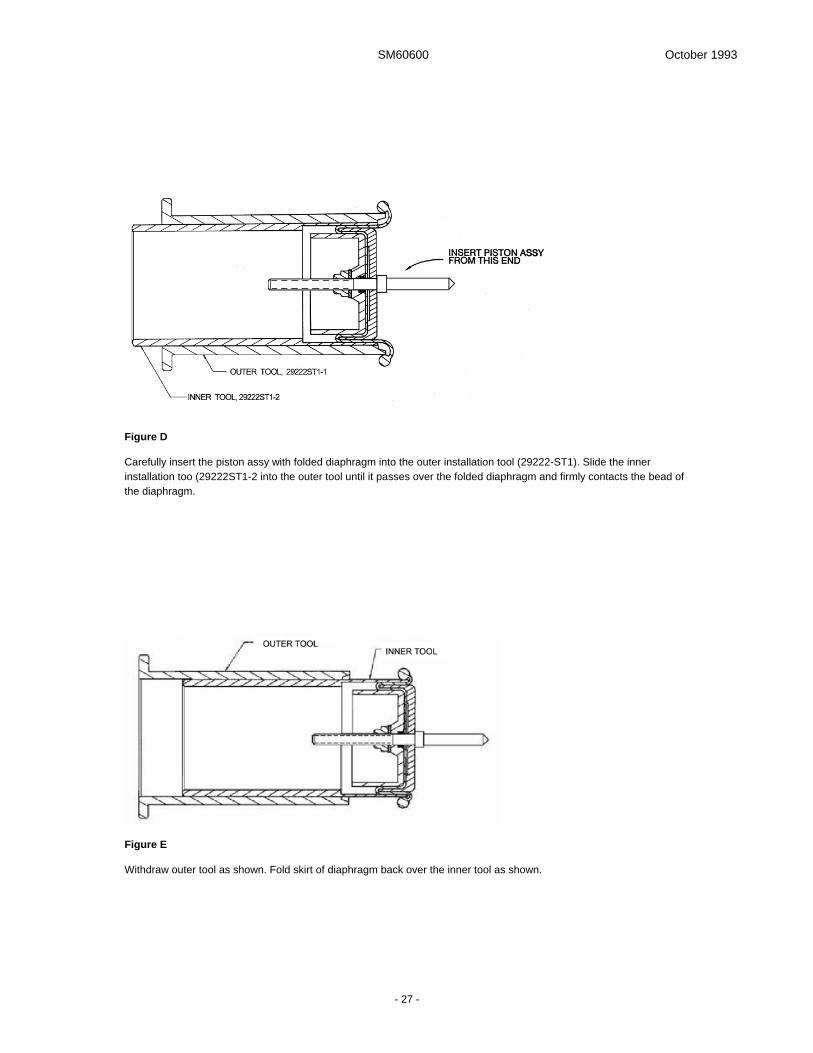
SM60600 October 1993
- 27 -
Figure D
Carefully insert the piston assy with folded diaphragm into the outer installation tool (29222-ST1). Slide the inner installation too (29222ST1-2 into the outer tool until it passes over the folded diaphragm and firmly contacts the bead of the diaphragm.
Figure E
Withdraw outer tool as shown. Fold skirt of diaphragm back over the inner tool as shown.

SM60600 October 1993
- 28 -
Figure F
Install tool and piston assy into housing (3-21) and while pressing firmly on the inner tool, push stem (3-61) until it seats into pilot valve seat (3-40).
Figure G
While pressing gently but firmly on the inner tool, install the diaphragm bead into groove by pushing on the outer tool. Retain pressure on the outer tool and remove the inner tool as shown in Figure H, below.
Figure H

SM60600 October 1993
- 29 -
Figure I
While pressing on stem (3-61), remove the outer tool.
Figure J
Inspect to assure that the bead of the diaphragm contacts the wall of the cavity in the housing (3-21) on its entire outer diameter and remains in the groove. Install adapter (1-P or 1-Q).
E. Place unit in a small soft-jawed vise with open end of Housing Assy (3-1) up.
CAUTION:
Do not over- tighten vise and damage Housing Assy (3-1).
Place Spring (3-9) in the Housing Assy (3-1) so its inside diameter is over pilot diameter of seal Retainer (3-6).
F. Assemble O-ring (3-10) to groove in o-ring Retainer (3-11). Use Retainer (3-11) to compress Spring (3-9) until O-ring (3-10) enters Housing Assy (3-1) and cotter Pin (3-12) can be installed to secure Retainer (3-11).
CAUTION:
Do not pinch O-ring (3-10) during this operation. Spread ends of cotter Pin (3-12).
11.5.3 Functional Verification of Pressure Relief Valve

SM60600 October 1993
- 30 -
Functional and pressure tests of the pressure relief valve are accomplished in conjunction with test of the complete automatic pressure control coupler in a later section of this document. Preliminary functional verification is accomplished as follows:
A. Place flat end of adjusting Nut (3-14) against a flat, sturdy surface. Press relief valve assembly against the surface with sufficient force to open the relief valve; then relieve the force and allow relief valve to return to its seat.
The movement should be smooth without indications of hang up and the valve should return to its seat when the force is relieved.
B. With the valve closed, attempt to blow through the hole in the end of Extension (3-16). There should be no indications of air leakage past the seat, or past O-rings (3-10 & 3-15).
11.6 Female Half Quick Disconnect (1-F, G, H & J)
Replace all parts found defective in the inspection procedures above.
A. Assemble the Retainer Ring (4-7) into Sleeve (4-6). Spread ends of the Retainer Ring (4-7) and slide both parts over Housing (4-5). Temporarily allow Retainer Ring (4-7) to seat in the Housing (4-5) groove nearest the pipe threaded end.
B. Set Housing (4-5) on end in a shallow container with the disconnect end up. Use a cotton-type swab to place a small amount of petroleum jelly on the bottom of each of the 24 holes in the Housing (4-5).
C. Carefully insert 24 Balls (4-8) into the holes in the Housing (4-5). The petroleum jelly should hold the balls in place while the ends of the Retainer Ring (4-7) are spread and the Sleeve (4-6) is moved to the engaged position, capturing the Balls (4-8).
D. When Balls (4-8) are captured, wash all petroleum jelly out either by immersion in clean solvent or by use of a spray bottle containing clean solvent. Allow to air dry, or blow dry with clean filtered, dry compressed air.
E. Spread Retainer Ring (4-7) and assemble into groove closest to threaded end on Housing (4-5).
F. Keep Retainer (4-4) and Screws (4-3) handy for final assembly as noted later.
11.7 Limited Quick Disconnect Assy (1-K)
Replace all parts found defective in the inspection procedures above with new parts. Refer to Figure 4C and proceed as follows:
A. Assemble retainer Ring (4-7) to ball retaining Sleeve (4-6). Spread ends of retainer Ring (4-7) and slide both parts over Housing (4-21). Temporarily allow retainer Ring (4-7) to seat in Housing (4-21) groove nearest the pipe threaded end.
B. Set Housing (4-21) on end in a shallow container with the disconnect end up. Use a cotton-type swab to place a small dollop of petroleum jelly on the bottom of each of the 24 holes in Housing (4-21).
C. Carefully insert 24 Balls (4-8) into 24 holes in Housing (4-21). The petroleum jelly should hold the Balls (4-8) in place while end of the retaining Ring (4-7) are spread and the ball retaining Sleeve (4-6) is moved to the engaged position, capturing the Balls (4-8).
D. When Balls (4-8) are captured, wash all petroleum jelly out either by immersion in clean solvent
or by use of a spray bottle containing clean solvent. Allow to air dry, or blow dry with clean filtered, dry compressed air.
E. Spread lock Ring (4-1) and assemble into outer groove in Housing (4-21).
F. Temporarily assemble ring Retainer (4-4) to ball retaining Sleeve (4-6) with Screws (4-3).
11.8 Carriage Assy (1-W)
Place the feet of the Strut (7-16) in a soft jawed vise to hold it firmly with the feet flat on the work bench. Install Latch (7-13), Clevis Pin (7-15) and Cotter Pin (7-14) into Strut (7-16). Install one Screw (7-4) and Washer (7-5) into Shaft (7-16). Place one Washer (7-6) onto Shaft (7-16) and then place Shaft (7-16) through one hole of the Flange (7-9) and Lever (7-10). Place another Washer (7-6) between the Lever (7-10) and Strut (7-16). Place this sub-assembly into position with the Strut (7-16) and the Spring (7-8). The straight tang of the Spring (7-8) is to be placed in the hole in the Strut (7-16).
Caution!
Be very careful during the next phase of the assemble. The Spring (7-8) is very strongly loaded and could cause personal injury if not controlled properly.
Grasp the Spring (7-8) with a pair of battery pliers (channel locks) with the straight tang toward the left. Using a pair of vise grips in the right hand grasp the spring and rotate the spring until the bent tang is approximately into position under the Flange (7-9). Holding the Spring (7-8) with the vise grips, tap or push the Shaft (7-7) through the Spring (7-8) to engage the Shaft (7-7) into the other hole of the Strut (7-16) and on through the other parts. Note that at least one Washer (7-6) should be placed between the Strut (7-16) and Lever (7-10) and between the Lever (7-10) and the Flange (7-9). The actual number of Washers (7-6) used is determined by the side clearance of the assembled parts. Fasten in place with the other Screw (7-4) and Washer (7-5). Check the side play of the assembled parts. Add Washers (7-6) to adjust the clearance to no more than 0.06 (1.52 mm).
Install Spring (7-11) and Washer (7-12) into recess in Strut (7-16).
Final Caution!
If Carriage Assy (1-W) is latched when it is not attached to the unit, unlatching may be injurious to your person. Be very careful in unlatching the Carriage Assy (1-W) in this position.
11.9 Guard Assemblies, options L and M
Reassemble Guard Assemblies (1-L & 1-M) being sure to utilize an appropriate pipe thread sealant on all pipe threads. The use of Teflon tape is not recommended for this application. Thread sealant 56747 made by Locktite Corporation is recommended. Any fuel resistant liquid or paste sealant will suffice.
11.10 Final Assembly
Verify that the Coupler Subassembly (1-5), the Female Half Quick Disconnect (1-F, G, H, J or K), Pressure Control Elbow Assembly (1-1), the Collar Stop Assembly (1-6), and the Carriage Assy (1-W), if used, have been overhauled and reassembled.
A. Install and adjust Pressure Relief Valve (1-2) as follows:

SM60600 October 1993
- 31 -
1. Temporarily foreshorten Pressure Relief Valve (1-2) by tightening Extension (3-16) onto Housing Assy (3-1) until O-ring (3-17) and Extension (3-16) can be inserted in hole provided on the inner lower surface of the unit inlet with the two Spring Pins (3-3) positioned directly below the two holes in the unit Housing Assembly (3-1).
2. Then, turn pressure relief valve Extension (3-16) in the unscrew direction so the two spring Pins (3-3) are fully inserted in the unit housing assembly and the adjacent surfaces of the pressure relief valve housing assembly bottom on the unit housing assembly. Use 0.020 inch (0.5 mm) lockwire to lockwire the pressure relief valve Extension (3-16) to Pressure Relief Valve Housing (3-2) as observed in the disassembly paragraph of this manual so that rotation of the Extension (3-16) in the direction that foreshortens the pressure relief valve tightens the lockwire.
3. Loosen hex Nut (3-13) on relief valve Shaft (3-4). Place a parallel bar of known thickness across coupler flange of the unit Housing (3-1) adjacent to the pressure relief valve. Turn pressure relief valve adjusting Nut (3-14) until a depth micrometer measurement from the end of the adjusting nut to the parallel bar plus the parallel bar thickness is between 1.560 and 1.580 inches (39.6 and 40.1 mm). Then, tighten hex Nut (3-13) to lock adjusting Nut (3-14) position.
EXAMPLE:
If parallel bar thickness is 0.250 inches (6.35 mm), then depth micrometer reading should fall between 1.310 and 1.330 inches (33.3 - 33.8 mm).
B. Lubricate and assemble O-ring (2A-10) onto the outlet of the Coupler (1-5), exerting care that the o-ring is not pinched. Fasten with six socket head Screws (2A-2) and Washers (2A-3), also securing tab of Dust Cap Assembly (1-4), if used, and Collar Stop Assembly
(1-6). Be sure and install Collar Stop Assembly (1-6) in the same location from which it was removed. (See Figure 6). Torque Screws (2A-2) to 90 ±10 inch-pounds (1.04 ± 0.12 m-kg).
C. Lubricate and assemble O-ring (4-15) onto pilot diameter of male half of Quick Disconnect (1-D or K). Assemble to outlet of Pressure Control Elbow Assy (1-1) with Screws (4-12) and Washers (4-11). Torque screws (4-12) to 90 ±10 inch-pounds.
D. On options F, G, H or J, lubricate Seal (4-9) and install Quick Disconnects (1-F, G, H or J) onto Outlet (1-D). To do so remove Screws (4-3) and Retainer (4-4). Pinch ends of Ring (4-7) together and slide Sleeve (4-6) to release Balls (4-8). Once the Outlet (1-D) is in place slide Sleeve (4-6) back into place to lock Balls (4-8) into groove in Outlet (1-D), release Ring (4-7), replace Retainer (4-4) and secure with Screws (4-3). Lockwire the Screws (4-3). Reposition Lock Ring (4-1) into groove closest to Sleeve (4-6).
E. If unit incorporates option C, product selector set (1-C), install bolts in desired positions so that bolt head is flush with or no more than 0.03 inch (0.76 mm) below the adjacent collar surface.
F. If the Carriage Assy (1-W) is utilized, the three longer Bolts (7-19) and the extra long Bolt (7-20) will be used in lieu of the standard Bolts (2A-2) for its installation. The Washers (7-18) will be used as spacers as shown in Figure 8 on both sides of the Flange (7-9) and 10 each will be used under Bolt (7-20) as a stop for the Folding Handle (2B-37). Note, the Carriage Assy (1-W) should be installed in the non-retracted position.
Screws (2A-2), (7-19) and (7-20) should be torqued to 90 ± 10 in.-lbs. (104 ± 12 kg.-cm.).
G. If option X is utilized, install Guard and Handle Assembly (1-X) with four each Screws (1-26) and Washers (1-27).
12.0 TESTING
12.1 Test Equipment
The following test equipment is required:
• Inlet test adapter conforming to API Bulletin 1584 with pressure equalization valve such as Carter 60505D or 61526D.
• Outlet test adapter to mate pipe threads in outlet.
• 0-300 psig fuel or test solvent pressure source.
• 0-125 psig air pressure source.
• Shutoff valves, regulators, pressure gauges, and other miscellaneous test equipment. (See Figure K).
12.2 Test Conditions
Test media shall be Stoddard Solvent (Federal Specification P-D-680), JP-4 per MIL-J-5624, Jet A or equivalent.
12.3 Bench Test
12.3.1 Coupler Functional Test
A. With the Collar (2A-27) retracted (Unit not attached to an adapter and closed), verify that the opening Handle (2B-37) cannot be rotated to the open position.
B. Depress and release the Detent Pin (2A-26) several times to verify that the pin promptly extends
and locks the Collar (2A-27) each time it is released. Rotate the Detent Pin (2A-26) in 90° increments and repeat this operation at each position to verify that there is no position at which the Detent Pin (2A-26) hangs retracted.
C. With the Collar (2A-27) retracted, place the Coupler squarely over an unpressurized, vented Carter 60505D or 61526D Adapter so the face of the adapter depresses the Detent Pin (2A-26). The Collar (2A-27) should drop freely in a positive manner into the engaged position with no hesitation, sticking or binding. With the Collar (2A-27) extended, it should be impossible to separate the Unit from the test adapter. Retract the Collar (2A-27), depressing the Collar Lock Assembly (1-6) at the same time, and lift the unit off of the adapter. The Detent Pin (2A-26) should extend and prevent extension of the Collar (2A-27).
D. Repeat C several times. Then, engage the Unit to the adapter and open and close the Poppet (2A-15) by rotating the operating Handle (2B-37), while verifying that it is not possible to retract the Collar (2A-27) with the Handle (2B-37) in any position but the fully closed position. The Collar Stop Assembly (1-6), if present, should automatically engage the Collar (2A-27) each time the Collar (2A-27) becomes extended preventing the retraction of the Collar (2A-27) until it is manually depressed.

SM60600 October 1993
- 32 -
E. Repeat D several times. Then, retract the Collar (2A-27) and separate the Unit from the adapter. Verify that the Detent Pin (2A-26) has extended and locked the Collar (2A-27) in the retracted position. Verify that the Poppet (2A-15) can not be opened with the Collar (2A-27) retracted.
12.3.2 Proof Pressure, Leakage
A. Connect coupler to standard API adapter. Block unit Piston Assy (3-22) open with a large O-ring, Teflon bearing from a 60427 nozzle or similar soft object. With coupler poppet in full open position, completely fill unit with test fuel or solvent. Allow unit Piston Assy (3-22) to close. Stand unit in normal upright position. Remove pan head Screw (3-87) and apply enough fluid pressure to completely bleed all air from unit. Reinstall pan head Screw (3-87) and Stat-o-seal (3-86).
B. Remove pilot cavity Plug (3-78) and fill the cavity with test fuel or solvent. Apply 75 PSIG to unit air port for five minutes. No Diaphragm (3-63) leakage is allowed. Drain test fuel or solvent from pilot cavity and reinstall pilot cavity Plug (3-78).
C. Rotate unit so the outlet is up. Fill outlet with test fuel or solvent until unit Piston Assy (3-22) and Piston Guide (3-34) are covered with test fuel or solvent. Apply 75 PSIG to unit air port and examine unit Piston Assembly (3-22) and piston Guide (3-34) for air leakage. Vent air and dump test fuel or solvent from outlet.
D. Return unit to normal position and apply 300 PSIG to API adapter and to outlet for a minimum of one minute. Check housings and joints for signs of fuel leakage. No leakage is permissible.
E. Remove pressure and connect source to outlet of the unit. Close coupler poppet and disconnect coupler from API adapter. Apply 5 PSIG to the outlet for a minimum of one minute; check for leakage at all sealing surfaces.
12.4 Flow Tests and Adjustments
Figure K is a simplified schematic diagram of a test system suitable for testing and adjusting the unit. This simplified schematic diagram includes only the equipment necessary to test the unit. Other equipment desirable for easy installation and removal of the test item have been intentionally omitted.
The unit is flow tested and adjusted as follows:
A. With the unit installed in a test system similar to Figure K, with V-l closed, V-2 partly open, V-3 closed (released), V-4 open, loosen pilot cavity Plug (3-78) and allow head of fuel in storage tank to fill the fuel side of pilot valve diaphragm chamber and force the air out. When all air is bled, tighten the pilot cavity Plug (3-78).
B. Adjust the air pressure regulator to provide 75 PSIG air pressure at P-3. Start the pump and adjust the bypass regulator to provide 120 PSIG at P-l
C. Open V-l. Squeeze deadman air valve. Unit will begin to open and pass fuel. Adjust V-2 to achieve a flow rate between 100 and 1000 US GPM.
NOTE: The unit may appear to jump open on the initial operation because of air in the area behind the Piston Assembly (3-22). If this occurs, close and open the unit several times to purge the air by releasing and squeezing the deadman air valve. The unit may be bled of all air by removing pan head Screw (3-87) with a head of fuel present at the valve inlet. Reinstall pan head Screw (3-87) prior to operation in the test system.
D. While flowing at a stabilized flow rate between 100 and 1000 US GPM, read pressure on P-2. With 75 PSIG air pressure on P-3, P-2 should read 50 ± 2 PSI for a 25 PSI bias adjustment which is the factory recommended bias setting. Never set the bias at less than 15 PSI. If P-2 is high or low, adjust the bias setting as follows:
1. Close V-l or shut pump down. It may be necessary to momentarily squeeze the deadman valve while closing the coupler poppet to relieve a hydraulic lock.
2. Close V-4 and remove pilot cavity plug (3-78) from the unit, capturing fuel that spills from pilot chamber.
3. Refer to Figure 3 and use adjustment Lock Clip (3-76) to rotate both the high capacity pilot valve adjustment Nut (3-75) and the pilot valve bias spring adjustment Screw (3-74) in the correct direction. Rotation in the clockwise direction increases the bias setting and will reduce the pressure at P-2. Rotation in the counterclockwise direction will decrease the bias setting and will increase the pressure of P-2. One complete revolution of the bias spring adjustment Screw (3-74) will change the pressure at P-2 by approximately 6 PSI, raising the P-2 pressure when done in the counterclockwise direction and lowering the pressure at P-2 when done in the clockwise direction as long as the air pressure is not changed.
4. When both the adjustment Screw (3-74) and Nut (3-75) have been rotated the proper amount in the proper direction, withdraw the adjustment lock Clip (3-76), apply deadman air to raise the pilot valve and rotate the adjustment Nut (3-75) (only) an equal amount in the same direction (to the nearest 1/4 turn).
EXAMPLE: The average (or nominal) pressure at P-2 was 53 PSIG while flowing at a stabilized flow rate between 100 and 1000 US GPM with 75 PSIG air pressure. The bias setting is 75 minus 53 or 22 PSI rather than the desired 25 PSI. To increase the bias by 3 PSI it is necessary first to turn both the Nut (3-75) and Screw (3-74) 1/2 revolution in the clockwise direction since 3 PSI is 1/2 of the 6 PSI furnished by a complete revolution. Then it is necessary to turn the Nut (3-75) (only) an additional 1/2 turn in the same (clockwise) direction to maintain approximately the same high capacity pilot valve adjustment since the pilot valve bias spring adjusting Screw (3-74) thread pitch is approximately 1/2 the pitch of the adjustable Nut (3-75) for high capacity pilot valve setting. Applying deadman air to raise the pilot valve simplifies the final part of the adjustment where it is desired to only turn the Nut (3-75).
5. Release the deadman valve, reinsert the adjustment lock Clip (3-76) through both the adjustment Nut (3-75) and adjustment Screw (3-74) and partly install the pilot cavity Plug (3-78). Open V-4 and allow the fuel storage head to fill the sense fuel pressure passages while air is bled past pilot cavity Plug (3-78). Then tighten the Plug (3-78).
E. Start the pump and/or open V-l. Squeeze the deadman air valve to apply 75 PSIG air pressure to the unit. The unit will open and flow at the rate limited by the position of V-2. When the flow rate has stabilized, recheck P-2, which should read 50 ± 2 PSIG, with 75 PSIG air pressure following the bias setting fine adjustment.
F. Open V-2 to increase flow rate to 1000 US GPM while observing P-2. P-2 should remain at 50 ± 2 PSIG.

SM60600 October 1993
- 33 -
G. While flowing at a stable flow rate of 1000 US GPM, use a stop watch to measure the time from deadman air release to unit closure. The high capacity pilot valve can be adjusted to close the unit from 1000 US GPM in the range of a fraction of a second (if the deadman air valve and hose do not have small restrictions) to 10 seconds. Very fast closure time may introduce unwanted pressure surges in the upstream plumbing. Very slow closure times may allow passage of unwanted amounts of fuel after deadman air release. The factory setting is an arbitrary 2-3 seconds (as a compromise between these extremes) unless the customer has specified faster or slower closure times. The length of the deadman hose system may have an affect upon the system closing time. The hose should be maintained to a bare minimum for this test to determine the closing time of the unit and not be affected by the deadman system. Should it be necessary to adjust the shutdown time, proceed as follows:
1. Close V-4. Remove pilot cavity Plug (3-78) and adjustment lock Clip (3-76). Apply deadman air pressure to raise the pilot valve.
2. Turn the adjustable Nut (3-75) for high capacity pilot valve setting (only) in the desired direction in 1/4, 1/2, 3/4 or full revolution increments. Turning the adjustable Nut (3-75) in the clockwise direction will result in slower unit closure time. Turning the adjustable Nut (3-75) in the counterclockwise direction will result in faster closure time. Completely removing the adjustable Nut (3-75) will result in the fastest possible closing time. Reinstall Clip (3-76).
3. Reinstall pilot cavity Plug (3-78), opening V-4 to fill and bleed the fuel sense chamber, and then tighten Plug (3-78).
Figure K Simplified Test System Schematic Diagram
H. Repeat steps F and G until closing time is within desired range.
I. Open unit with deadman air valve and flow 1000 US GPM. Then reduce flow in increments by progressively closing V-2. Verify that P-2 restabilizes at 50 ± 2 PSIG at each reduced flow rate down to 100
US GPM. Then release deadman valve, close V-l and remove test article from test system.
12.5 POST TEST PROCEDURE
After removing unit from test system place on an adapter housing and open poppet to drain fuel.
13.0 STORAGE
If it is necessary to store the unit for any length of time, install the dust cap and cover the outlet, with a
moisture barrier paper or film to protect it from the effects of dust and high humidity.

SM60600 October 1993
- 34 -
14.0 ILLUSTRATED PARTS CATALOG
Tables 1.0 through 6.0 tabulate the parts and sub-assemblies comprising the 60600 & 60600-2 Model Hydrant Pressure Control Coupler including all available options.
The item numbers of the table are keyed to the exploded views shown in Figures 1 through 7B.
TABLE 1.0 60600 & 60600-2 Coupler and Options
Fig Item Part Number Description Units/ Assy
Coupler Option
Spares/10 Units/yr
1A 1 41806 Pressure Control Elbow Assy 1 All - 2 41813 Pressure Relief Valve 1 All - 3 41731 Folding Handle 1 All - 4 44660 Dust Cap 1 All - 5 61525 Lower Half Coupler Assy 1 60600 - 5A 61525S Lower Half Coupler Assy (Short Stroke) 1 60600-2 - 5 6 44140 Collar Stop Assy 1 All - 1A C GF4-7A Product Selection 5 C - 4B D 44219 Male Half Outlet 1 D - 4A F 44220-1 Female Half, 3" NPT 1 F - G 44220-2 Female Half, 3" BSPP 1 G - H 44220-3 Female Half, 4" NPT 1 H - J 44220-4 Female Half, 4" BSPP 1 J - 4C K 44530 Limited Quick Disconnect, 3" NPT 1 K - 1B L 44600 Pilot Valve Guard w/ ¼" NPT Ports 1 L - 7 2706-4-4LN Fitting 2 L - 8 209424 Bracket 1 L - 9 209425 Guard 1 L - 10 GF35207-281 Screw 4 L - 11 101-01 Washer 8 L - 12 GF35650-3252 Nut 4 L - 13 2404-4-4 Fitting 2 L - 14 4TS4RJ4-0004.38 Hose 2 L - 15 5503-4-4 Fitting 2 L - 16 GF35207-298 Screw 4 L - 1B 17 102-01 Washer 8 L - M 44600-1 Option L with Air/Fuel Sense Plug 1 M - 7 2706-4-4LN Fitting 2 L - 8 209424 Bracket 1 M - 9 209425 Guard 1 M - 10 GF35207-281 Screw 4 M - 11 101-01 Washer 8 M - 12 GF35650-3252 Nut 4 M - 13 2404-4-4 Fitting 2 M - 14 4TS4RJ4-0004.38 Hose 2 M - 15 5503-4-4 Fitting 2 M - 16 GF35207-298 Screw 4 M - 17 102-01 Washer 8 M - 18 61498 Air Fuel Sense Plug 1 M - 1B 18A 44666 Cover Assy 1 M 2 1A 19 41794 Handle Assembly 1 All - 1C 20 29246 Bar 1 All - 21 29262 Grip 2 All 6 22 29399-1 Bracket 1 All 2 23 29399-2 Bracket 1 All 2 24 GF960-516L Washer 2 All but M - 25 GF35207-296 Bolt 2 All but M - 1A P 41807-1 Adapter, Air/Fuel Sense, ¼" NPT 1 P - Q 41807-2 Adapter, Air/Fuel Sense, ¼" BSPP 1 Q - X 41795 Guard & Handle Assy 1 X -

SM60600 October 1993
- 35 -
Fig Item Part Number Description Units/ Assy
Coupler Option
Spares/10 Units/yr
1D 26 GF35207-296 Screw 6 X - 27 GF960-516L Washer 6 X - 28 29245 Strap 2 X - 29 29246 Support 1 X - 30 29262 Grip 2 X 4 1A W 60532B Carriage Assy 1 W - 3A AA 29224-1 Orifice 1 AA - BB 29224-2 Orifice 1 BB - CC 29224-3 Orifice 1 CC - DD 29224-4 Orifice 1 DD - -KD60600-1 Kit - Contains all soft goods (seals) and other necessary parts to overhaul a 60600 Coupler that utilizes obsolete Lower
Half Couplers 42221 and 42221-1. Contains items - 1-30, 2-10, 2-13, 2-17, 2-18, 2-21, 2-22, 2-23, 2-25, 2-28, 2-32, 2-33, 3-5, 3-10, 3-15, 3-17, 3-23, 3-26, 3-27, 3-30, 3-31, 3-32, 3-35, 3-36, 3-40, 3-41, 3-42, 3-43, 3-44, 3-45, 3-50, 3-51, 3-52, 3-55, 3-59, 3-60, 3-63, 3-67, 3-77, 3-83, 3-86, 4-15, MS29513-020 & 207521.
- KD60600-2 Kit - Contains all parts from the KD60600-1 (except the special cotter key used in the 42221) plus the parts needed to upgrade the Lower Coupler Half to the higher strength 44665 (61525). Contains items -1-30, 2-9, 2-10, 2-11, 2-12, 2-13, 2-14, 2-15, 2-16, 2-17, 2-18, 2-20, 2-21, 2-22, 2-23, 2-25, 2-28, 2-32, 2-33, 3-5, 3-10, 3-15, 3-17, 3-23, 3-26, 3-27, 3-30, 3-31, 3-32, 3-35, 3-36, 3-40, 3-41, 3-42, 3-43, 3-44, 3-45, 3-50, 3-51, 3-52, 3-55, 3-59, 3-60, 3-63, 3-67, 3-77, 3-83, 3-86 & 4-15.
- KD60600-3 Kit - Contains all soft goods (seals) and other necessary parts to overhaul a 60600 Coupler that utilizes the newer 44665 (61525) Lower Coupler Half. Contains items -1-30, 2-10, 2-11, 2-12, 2-13, 2-17, 2-18, 2-21, 2-22, 2-23, 2-25, 2-28, 2-32, 2-33, 3-5, 3-10, 3-15, 3-17, 3-23, 3-26, 3-27, 3-30, 3-31, 3-32, 3-35, 3-36, 3-40, 3-41, 3-42, 3-43, 3-44, 3-45, 3-50, 3-51, 3-52, 3-55, 3-59, 3-60, 3-63, 3-67, 3-77, 3-83, 3-86 & 4-15.
- KD41813 Kit - Contains the seals to overhaul the 41813 Relief Valve Assy. Contains items - 3-5, 3-10, 3-15 & 3-17.

SM60600 October 1993
- 36 -
TABLE 2.0 Lower Coupler Half
Fig Item Part Number Description Units/ Assy
Coupler Option
Spares/10 Units/yr
1A 5 44665 Coupler, Lower Half 1 60600 - 5A 44675 Coupler, Lower Half 1 60600-2 - 2A 1 Left intentionally blank 2 GF24673-16 Screw 6 60600 & -2 - 3 GF960C516 Washer 6 60600 & -2 - 4 Left intentionally blank. 5 43945 Body 1 60600 & -2 - 6 GF4-4A Screw 1 60600 & -2 - 7 GF35338-44 Lockwasher 1 60600 & -2 - 8 28781 Washer 1 60600 & -2 - 9 201286 Key 1 60600 & -2 - 10 MS29513-249 O-ring 1 60600 & -2 10 11 202010 Cotter Pin 1 60600 & -2 2 12 NAS1169C10 Washer 1 60600 & -2 - 13 28765 Bearing 1 60600 & -2 5 14 210004 Pin 1 60600 & -2 1 15 209600 Poppet 1 60600 1 15A 210139 Poppet 1 60600-2 1 16 209601 Link 1 60600 & -2 1 17 28755 Seal, Nose 1 60600 & -2 10 18 209837-347 Quad-ring 1 60600 & -2 10 201201-347 O-ring 1 Alternate 10 19 29232 Wave Washer 4 60600 & -2 - 19A 210587 Wave Washer 1 60600 & -2 - 20 209996 Crank Shaft 1 60600 - 210141 Crank Shaft 1 60600-2 - 21 200103 Washer 1 60600 & -2 2 22 203563 Bearing 1 60600 & -2 10 23 29221 Bearing 1 60600 & -2 10 24 29216 Bearing 2 60600 & -2 10 25 MS29513-212 O-ring 1 60600 & -2 10 26 200689 Detent Pin 1 60600 & -2 - 27 207482 Collar 1 60600 & -2 1 28 28928 Bumper 1 60600 & -2 1 29 RR-800-S Retaining Ring 1 60600 & -2 - 30 GF19060-4815 Ball 1 60600 & -2 - 31 28763 Spring 1 60600 & -2 - 32 28760 Lug Ring 4 60600 & -2 4 33 200688 Lug 16 60600 & -2 32 34 GF3-3A Bolt 1 60600 & -2 - 35 GF960C10L Washer 1 60600 & -2 - 36 GF35333-39 Lockwasher 1 60600 & -2 - 2B 37 41731 Folding Handle Assy 1 ALL - 38 29178 Pin 1 ALL - 39 GF9245-68 Cotter Pin 1 ALL 4 40 29179 Spring 1 ALL 10 41 GF51957-42 Screw 1 ALL 2 42 29177 Handle Cam 1 ALL 1 43 207355 Handle 1 ALL -

SM60600 October 1993
- 37 -
TABLE 3.0 Pressure Control Elbow Assy
Fig Item Part Number Description Units/ Assy
Coupler Option
Spares/10 Units/yr
1A 2 41813 Relief Valve Assy 1 All - 3B 1 41898 Housing Assy 1 All - 2 29432 Housing 1 All 3 GF171525 Pin 2 All 4 29434 Shaft 1 All 5 M83248/2-008
(was NAS1594-008) O-ring 1 All 10
6 29555 Seal Retainer 1 All - 7 NAS620C4 Washer 1 All - 8 GF21083C4 Nut 1 All 9 29436 Spring 1 All - 10 MS29513-013 O-ring 1 All 10 11 29433 Retainer 1 All - 12 GF24665-155 Cotter Pin 1 All 2 13 GF345C416 Nut 1 All 14 29442 Nut, Adjusting 1 All - 15 MS29513-009 O-ring 3 All 10 16 29539 Extension 1 All - 17 MS29513-006 O-ring 1 All 10 18-20 Left intentionally blank. 3A 21 41815 Housing Assy 1 All - 22 41823 Piston Assy 1 All - 23 210127 Seal 1 All 10 24 29478 Seal Retainer 1 All - 25 GF520C10R6 Screw 6 All - 26 MS29513-252 O-ring 1 All 10 27 28986 Seal 1 All 10 28 28985 Spring 1 All - 29 29248 Retainer 1 All - 30 29243 Seal 1 All 10 31 MS29513-117 O-ring 1 All 10 32 LP51957-45HQ Screw 4 All - 33 GF960C8L Washer 5 All - 34 29242 Guide 1 All - 35 MS29513-010 O-ring 2 All 10 36 28980 Seal 2 All 10 37 29247 Retainer 1 All - 38 28984 Spring 1 All - 39 28976 Piston 1 All - 40 29558 Seat 1 All 10 41 28982 Seal 1 All 1 42 MS29513-127 O-ring 2 All 10 43 29249 Seal, Slipper 1 All 10 44 MS29513-116 O-ring 1 All 10 45 MS29513-119 O-ring 1 All 10 46 29401 Housing 1 All - 47-48 Left intentionally blank. 49 29403 Spacer 1 All - 50 201201-012 O-ring 1 All 10 51 MS29513-007 O-ring 3 All 10 52 29556 Seal, Stem 2 All 20 53 29557-1 Washer 1 All - 3A 54 Left intentionally blank. 55 MS29513-118 O-ring 1 All 10

SM60600 October 1993
- 38 -
Fig Item Part Number Description Units/ Assy
Coupler Option
Spares/10 Units/yr
56-57 Left intentionally blank. 58 29233 Housing 1 All - 59 LP51957-32HQ Screw 4 All - 60 600-001-6 Stat-o-seal 4 All 8 61 29257 Stem 1 All - 62 29228 Retainer 1 All - 63 209402 Diaphragm 1 All 10 64 Left intentionally blank. 65 28973 Piston 1 All - 66 Left intentionally blank. 67 GF20364D832A Nut 1 All - 68 Left intentionally blank. 69 41807-1 Adapter - ¼" NPT Ports 1 All - 41807-2 Adapter - ¼" BSPP Ports 1 All - 70 GF16998-28 Screw 4 All - 71 COM/NAS620-10L Washer 4 All - 72 29406 Washer 1 All - 73 29223 Spring 1 All - 74 29254 Screw, Pilot Spring Adjustment 1 All - 75 29253 Nut, Closing Time Adjustment 1 All - 76 29404 Clip 1 All - 77 MS29512-10 Gasket 1 All 10 78 29405 Plug 1 All - 79 LP51957-42HQ Screw 6 All - 80 29338 Retainer 1 All - 81 29337 Screen 1 All - 82 29224-1 Screw, Orifice, Piston Dampening 1 AA - 29224-2 Screw, Orifice, Piston Dampening 1 BB - 29224-3 Screw, Orifice, Piston Dampening 1 CC - 29224-4 Screw, Orifice, Piston Dampening 1 DD - 83 600-001-10 Stat-o-seal 1 All 2 84 GF35207-259 Screw 1 All - 85 29224-5 Screw, Orifice, Pilot Supply 1 All - 86 600-001-¼ Stat-o-seal 1 All 2 87 GF35207-277 Screw 1 All - 88 GF24665-138 Cotter Pin 1 All -

SM60600 October 1993
- 39 -
TABLE 4.0 Quick Disconnects
Fig Item Part Number Description Units/ Assy
Coupler Option
Spares/10 Units/yr
4A F 44220-1 Female Half, 3" NPT 1 F - G 44220-2 Female Half, 3" BSPP 1 G - H 44220-3 Female Half, 4" NPT 1 H - J 44220-4 Female Half, 4" BSPP 1 J - 1 26961 Lock Ring 1 F,G,H,J - 2 GF20995C32 Lock Wire A/R F,G,H,J 1 Spool 3 GF35276-261 Screw 2 F,G,H,J 3 4 28383 Retainer 1 F,G,H,J 1 5 207253-1 Housing, 3" NPT 1 F - 207253-2 Housing, 3" BSPP 1 G - 207253-3 Housing, 4" NPT 1 H - 207253-4 Housing, 4" BSPP 1 J - 6 26960 Sleeve 1 F,G,H,J - 7 26962 Retainer Ring 1 F,G,H,J - 8 GF19060-4818 Ball 24 F,G,H,J 9 AR10400-248AC Seal 1 F,G,H,J 10 10 Left intentionally blank. 4B 1-D 44219 Outlet, Male Half 1 D - 11 GF960C516 Washer 9 D - 12 GF24673-16 Screw 9 D - 13 207291 Flange 1 D - 14 207483 Ring 2 D 2 15 MS29513-256 O-ring 1 D 10 4C 1-K 44530 Limited Quick Disconnect 1 K - 11 GF960C516 Washer 9 D - 12 GF24673-16 Screw 9 D - 15 MS29513-256 O-ring 1 D 10 16 41752 Flange Assy 1 K - 17 28382 Ring 2 K 2 18 201201-348 O-ring 1 K 10 19 28938 Flange 1 K - 20 41211-1 Quick Disconnect Assy 1 K - 1 26961 Lock Ring 1 K - 2 GF20995C32 Lock Wire A/R K 1 Spool 3 GF35276-261 Screw 2 K 3 4 28383 Retainer 1 K - 6 26960 Sleeve 1 K - 7 26962 Retainer Ring 1 K - 8 GF19060-4818 Ball 24 K 21 27374 Housing 1 K -
SM60600 October 1993
- 40 -
TABLE 5.0 Collar Stop Assy
Fig Item Part Number Description Units/ Assy
Coupler Option
Spares/10 Units/yr
1 6 44140 Collar Stop Assy 1 All - 5 1 207165 Stop 1 All - 2 207166 Bracket 1 All - 3 207167 Spring 1 All 1 4 GF20392-2C63 Pin 1 All - 5 GF24665-151 Cotter Pin 1 All 2 TABLE 6.0 60532B Carriage Assy, Option W
Fig Item Part Number Description Units/ Assy
Coupler Option
Spares/10 Units/yr
1 W 60532B Carriage Assy 1 W -
7A 1 GF51971-4 Nut 2 W - 2 GF35338-47 Washer 2 W - 3 203577 Caster 2 W - 4 GF35206-296 Screw 2 W - 5 GF35333-41 Washer 2 W - 6 GF960-816L Washer A/R W - 7 29745 Shaft 1 W - 8 29663 Spring, Torsion 1 W - 9 29664 Flange 1 W - 10 201041 Lever 1 W - 11 29665 Spring 1 W - 12 GF960-616L Washer 3 W - 13 29662 Latch 1 W 2 14 GF9245-44 Cotter Pin 1 W - 15 GF20392-5C73 Pin, Clevis 1 W - 16 29667 Strut 1 W - 7B 17 43590 Hardware Kit 1 W - 18 GF960C516 Washer 13 W - 19 GF16998-60 Screw 3 W - 20 GF5-14A Bolt 1 W - Notes: 1. All part numbers beginning with "GF" are interchangeable with those beginning with either "AN" or "MS". If the
"GF" is followed by three numbers it is interchangeable with and "AN" part, otherwise it is interchangeable with an "MS" part of the same number.
2. The recommended spare parts shown above are the number required to support 10 units for one year. In addition it is advisable to keep a spare coupler to interchange with any unit in the field that may exhibit a problem. The recommended quantities are based on the ratio of spare parts sold for each unit during a one year period of time. The actual quantity required will vary from location to location.

SM60600 October 1993
- 41 -
15.0 OBSOLETE PARTS INFORMATION
There is a long history of Carter coupler lower half changes that, through the years has not been particularly explained. The reasons for these changes are now lost, however we are providing a table that will detail the various couplers and the detail parts that were utilized in them. Many of these parts are no longer economical to continue to manufacture as spare parts. Hence we have made every effort to indicate the parts (kits) required to upgrade couplers older than the 42221-1.
The table below provides the history of the various Carter coupler lower halves. The exploded views provided in Figure 2 can be used as an assistance to identify the required parts. The major pictorial
differences between the newer and older couplers is in the Detent Pin (2A-26) area. Older couplers, such as the 41609, used two detent pins and a retaining ring instead of the Ball (2A-30). For this reasons it is not possible to totally interchange some of the parts on an item for item basis. The couplers are separated into two major areas:
• Linkage System • Collar - Body - Detent Pin
The latter part of the table provides an indication as to the availability of the various parts or their substitutes where the inventory has been depleted.
API Coupler Lower Half History of Parts Interchangeability Crank Shaft - Poppet - Link Area: Item 41609 42221 42221-1 42221-2 44665 44675 Crank Shaft 28756 42401 201422 200096 209996 210141 Pin ---- 200785 ----- ----- ----- ----- Cotter Pin 202010 98398D218 207521 207521 202010 202010 Washer 28762 GF960C616L ----- ----- NAS1169C10 NAS1169C10 Link (2) 28757 200687 201421 201421 209601 209601 Bearing 28765 ----- 28765 28765 28765 28765 Key GF20066-205 201286 201286 GF20066-205 201286 201286 Pin (link) 28766 GF9390-690 GF16555-647 GF16555-647 210004 210004 Disc (2) 28767 ----- ----- ----- ----- ----- Poppet 28754 200686 207991 208069 209600 210139 202307 Shaft 41740 ----- ----- ----- ----- ----- Shims 29381 ----- ----- ----- ----- ----- Collar - Body - Detent Pin Area: Item 41609 42221 42221-1 42221-2 44665 44675 Snap Ring RR-800-S RR-787-S RR-800-S RR-800-S RR-800-S RR-800-S Body 43944 200784 43945 43945 43945 43945 Detent Pin (2) 28761 200689 200689 200689 200689 200689 Detent Lock 28764 GF19060-4815 GF19060-4815 GF19060-4815 GF19060-4815 GF19060-4815 Notes: 1. All part numbers beginning with "GF" are interchangeable with those beginning with either "AN" or "MS". If the "GF" is
followed by three numbers it is interchangeable with and "AN" part, otherwise it is interchangeable with an "MS" part of the same number.
3. The above table reflects the various parts used on each of the couplers shown and their superseding parts. It is not necessarily true that the various parts shown supersede the equivalent older part. The table below indicates the superseding part or kit of parts for each of the older items shown above. Where "limited stock" is indicated, it is the status as of April 1, 1992. Please ask your Carter distributor to check with us for the current situation.

SM60600 October 1993
- 42 -
PARTS SUPPORT FOR THE VARIOUS PARTS USED IN OLDER COUPLERS Ordered Name Replacement Part Ordered Inventory Note 200096 Crank Shaft 210141 No longer available 200684 Collar KD44665-3 No longer available 200686 Poppet KD44665-2 No longer available 200687 Link KD44665-2 No longer available 201421 Link KD44665-2 Available through 1992 201422 Crank Shaft 209996 No longer available or KD44665-5 To get lower cost cotter. 202307 Poppet KD44665-2 Not available. 207481 Collar 44665 No Longer available. 207521 Headed Pin KD44665-2 Available thru 1992. 207991 Poppet KD44665-2 No Longer available. 208069 Poppet KD44665-6 No longer available 28754 Poppet KD44665-2 No longer available 28756 Crank Shaft KD44665-2 No longer available 28757 Link KD44665-2 Limited Stock/check stk. 28761 Detent Pin 44665 Available thru 1992. 28764 Detent Lock 44665 Available thru 1992. 28766 Pin KD44665-2 Limited Stock/check stk. 28767 Disc KD44665-2 Limited Stock/check stk. 29381 Shim KD44665-2 Limited stock/check stk. 41740 Shaft KD44665-2 No longer available 42401 Crank Shaft KD44665-2 No longer available. 200785 Pin KD44665-2 Limited Stock/check stk. 43944 Body 44665 Limited Stock/check stk. GF16555-647 Pin KD44665-2 Limited Stock/check stk. GF9390-690 Pin KD44665-2 No longer available
The kits mentioned above will provide various degrees of up grading of the older lower half couplers as explained below. The KD44665-1 Kit is included as a part of several of the upgrade/overhaul kits noted at the end of Table 1. KIT NUMBER DESCRIPTION KD44665-1 Up grades linkage system to new configuration with necessary seals & other parts to overhaul lower half.
Contains the following items (see Table 2.0): 2A-9, 2-10, 2A-11, 2A-12, 2A-13, 2A-14, 2A-15, 2A-16, 2A-17, 2A-18, 2A-20, 2A-21, 2A-22, 2A-23 & 2A-25.
KD44665-2 Up grades linkage system to new configuration. Contains the following items (see Table 2.0): 2A-9, 2A-11, 2A-12, 2A-13, 2A-14, 2A-15, 2A-16 & 2A-20
KD44665-3 Up grades collar/ring to current configuration. Contains the following items (see Table 2.0): 2A-27 & 2A-29.
KD44665-4 Combines -1 & -3. Contains the following items (see Table 2.0): 2A-9, 2A-10, 2A-11, 2A-12, 2A-13, 2A-14, 2A-15, 2A-16, 2A-17, 2A-18, 2A-20, 2A-21, 2A-22, 2A-23, 2A-25, 2A-27, & 2A-29.
KD44665-5 Up grades Crank Shaft & Cotter in 41609 to new configuration. Contains the following items (see Table 2.0): 2A-9, 2A-11, 2A-12 & 2A-20.
KD44665-6 Up grades linkage system in 42221-2 (short stroke) Couplers to new configuration. Contains the following items (see Table 2.0): 2A-9, 2A-11, 2A-12, 2A-13, 2A-14, 2A-15A, 2A-16 & 2A-20 (parts used on Option S only).
KD44665-7 Same as -2 except rework instructions included to rework existing 210422 Crank Shaft (countersink to one boss required). Contains the following items (see Table 2.0): 2A-11, 2A-12, 2A-13, 2A-14, 2A-15 & 2A-16.

SM60600 October 1993
- 43 -
Figure 1A 60600 & 60600-2 Hydrant Coupler and Options

SM60600 October 1993
- 44 -
Figure 1B Options L & M

SM60600 October 1993
- 45 -
Figure 1C 41794 Handle Assembly
Figure 1D 41795 Guard Assembly

SM60600 October 1993
- 46 -
Figure 2A
60600 & 60600-2 Hyrant Couplers Lower Half Assembly

SM60600 October 1993
- 47 -
Figure 2B Option B, Folding Handle To 60600 & 60600-2 Hydrant Coupler Lower Half Assembly

SM60600 October 1993
- 48 -
Figure 3A Pressure Control Elbow Assembly For 60600 & 60600-2 Coupler

SM60600 October 1993
- 49 -
Figure 3B Pressure Relief Valve Assembly

SM60600 October 1993
- 50 -
Figure 4A Options F, G, H & J To 60600 & 60600-2 Couplers
Figure 4B Option D Male Half Outlet To 60600 & 60600-2 Couplers

SM60600 October 1993
- 51 -
Figure 4C Option K Non-Swivel Quick Disconnect To 60600 & 60600-2 Couplers

SM60600 October 1993
- 52 -
Figure 5 Collar Stop Lock For 60600 Coupler
Figure 6 Collar Lock AssemblyMounting Instructions

SM60600 October 1993
- 53 -
Figure 7A 60532 Carriage Assembly

SM60600 October 1993
- 54 -
Figure 7B 60532 Carriage Assembly

SM60600 October 1993
- 55 -

Eaton Aerospace Group Conveyance Systems Division 9650 Jeronimo Road Irvine, CA 92618 Ph (949) 452-9500 Fax (949) 452-9992