Embed Size (px)
Citation preview
Small Angle Neutron Scattering, Part 1
Dr. Richard Heenan
ISIS Facility,
Rutherford Appleton Laboratory,
England
Goals of this course
• To show why a physicist/chemist/biologist might find neutrons (or even X-rays) helpful.
• To understand some details of what Small Angle Neutron Scattering (SANS) can tell us.
• To be aware of some other useful neutron techniques.
Acknowledgements and Apologies
• Thanks to Steve King, Jeff Penfold, Stephen Holt and others at ISIS for use of some of their teaching materials.
• Apologies: no correct historical perspective, the examples are all biased to work that I happen to know about or was involved with!
• Please ask me to SLOW down if I speak too fast.
Contents (approximate!)
• Large facilities for neutrons and X-rays
• Diffraction
• Introduction to SANS
• Neutron scattering length densities and contrast variation
• How to do a SANS experiment
• Dilute particles
• Interacting and concentrated systems
• Polymers and interfaces
• Biology
• Some other neutron techniques
• Gels, sheets, fractals, some more examples?, conlusions
Neutron Facilities: nuclear reactor or a particle accelerator
• Nuclear reactor – e.g. ILL (Grenoble), Saclay (Paris), HMI (Berlin), IRI (Delft), NIST(USA), Oak Ridge (USA) etc.
Fission of heavy nuclei in specially designed, reactor core produces neutrons ( but still up to 40MW of heat!)
• Accelerator based source – e.g. ISIS (RAL, near Oxford), IPNS (Chicago), LANSCE (Los Alamos), KEK (Japan), SINQ (Switzerland),SNS (Oak Ridge under construction), JSNS (Japan, under construction)
•Spallation of not so heavy nuclei by high energy protons.Each proton produces 10 – 20 neutrons. ( Heat from ISIS is ~ 200 kW, SNS will be 1 - 2 MW, much safer! )
• In both types of source a cold moderator (e.g. liquid H2) is used to slow neutrons down to useful energies for SANS.
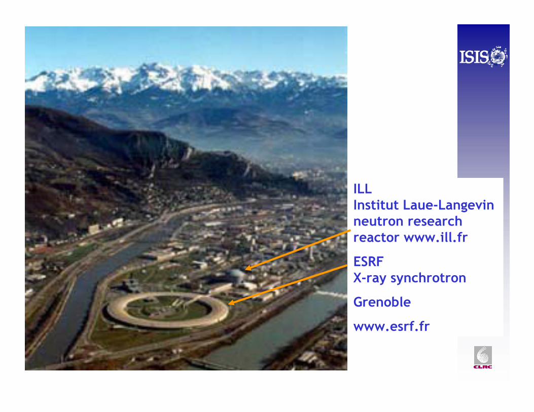
ILL Institut Laue-Langevinneutron research reactor www.ill.fr
ESRF X-ray synchrotron
Grenoble
www.esrf.fr
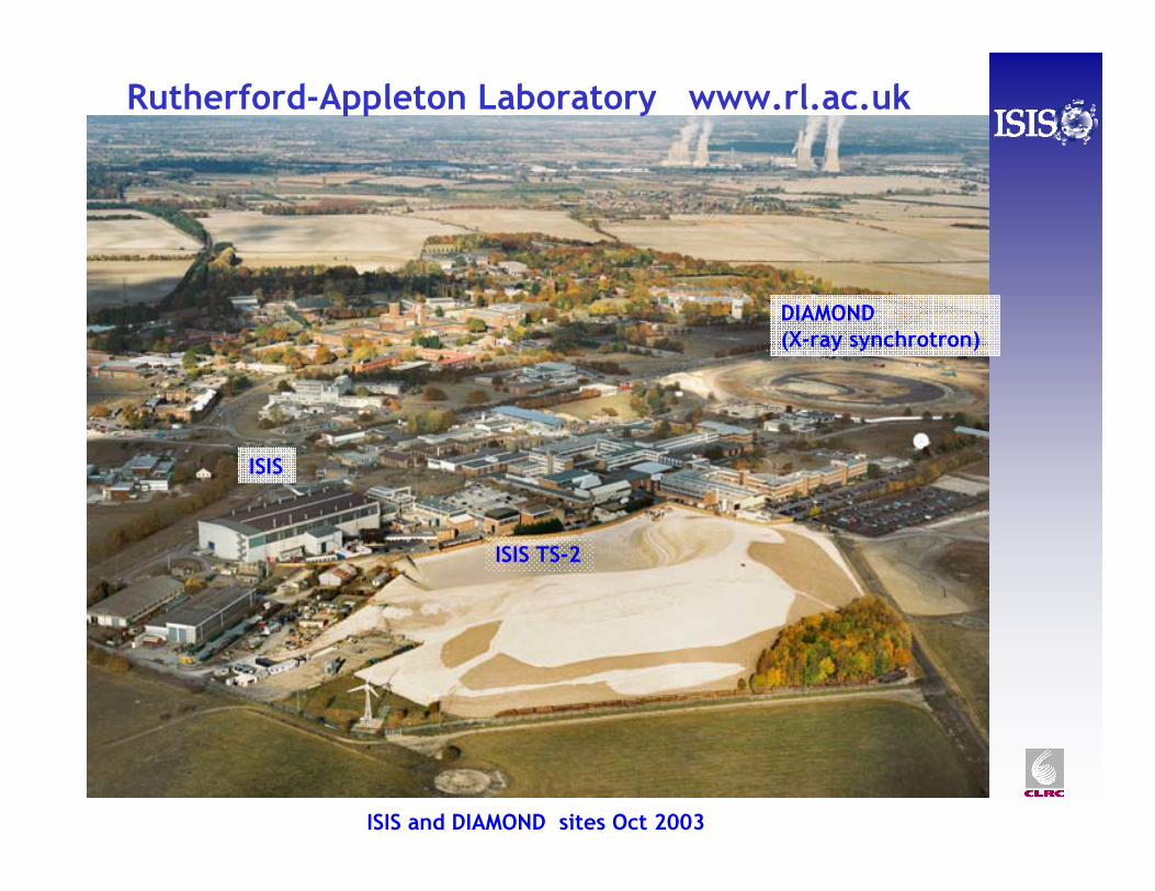
DIAMOND (X-ray synchrotron)
Rutherford-Appleton Laboratory www.rl.ac.uk
ISIS and DIAMOND sites Oct 2003
ISIS
ISIS TS-2
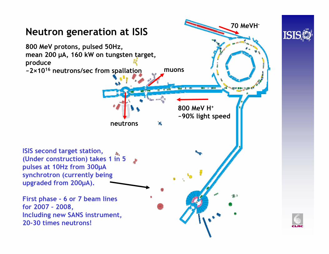
ISIS second target station, (Under construction) takes 1 in 5 pulses at 10Hz from 300μA synchrotron (currently being upgraded from 200μA).
First phase - 6 or 7 beam linesfor 2007 – 2008,Including new SANS instrument, 20-30 times neutrons!
Neutron generation at ISIS800 MeV protons, pulsed 50Hz, mean 200 µA, 160 kW on tungsten target,produce~2×10¹⁶ neutrons/sec from spallation
70 MeVH-
800 MeV H+
~90% light speedneutrons
muons
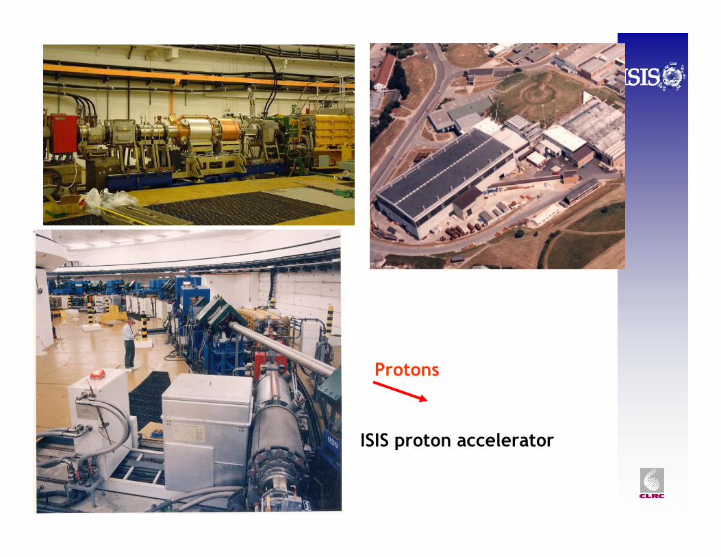
ISIS proton accelerator
Protons
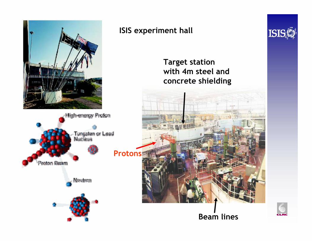
ISIS experiment hall
Target stationwith 4m steel and concrete shielding
Beam lines
Protons
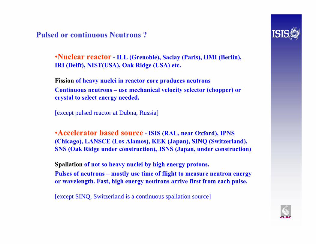
Pulsed or continuous Neutrons ?
•Nuclear reactor - ILL (Grenoble), Saclay (Paris), HMI (Berlin), IRI (Delft), NIST(USA), Oak Ridge (USA) etc.
Fission of heavy nuclei in reactor core produces neutronsContinuous neutrons – use mechanical velocity selector (chopper) or crystal to select energy needed.
[except pulsed reactor at Dubna, Russia]
•Accelerator based source - ISIS (RAL, near Oxford), IPNS (Chicago), LANSCE (Los Alamos), KEK (Japan), SINQ (Switzerland),SNS (Oak Ridge under construction), JSNS (Japan, under construction)
Spallation of not so heavy nuclei by high energy protons.Pulses of neutrons – mostly use time of flight to measure neutron energy or wavelength. Fast, high energy neutrons arrive first from each pulse.
[except SINQ, Switzerland is a continuous spallation source]
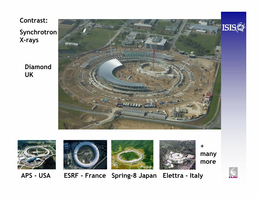
Contrast:
Synchrotron X-rays
APS - USA ESRF - France Spring-8 Japan
DiamondUK
Elettra - Italy
+ manymore
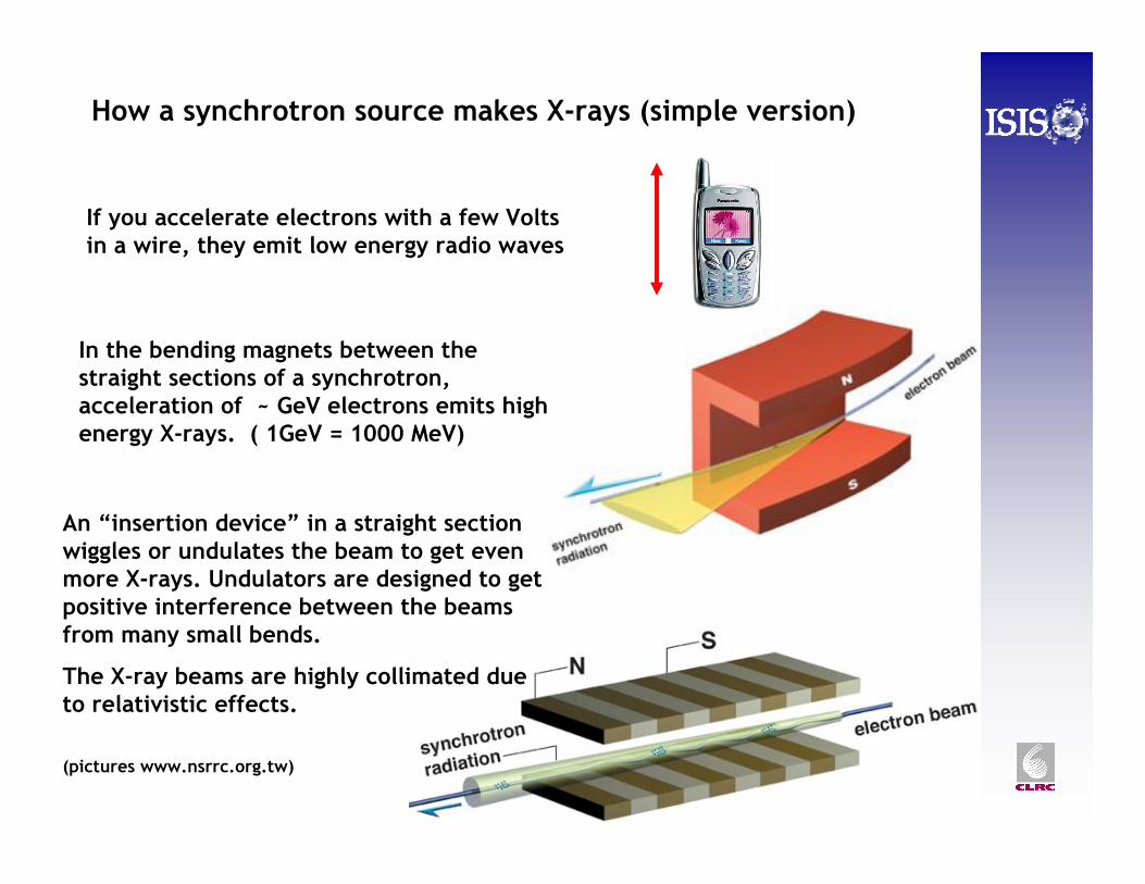
How a synchrotron source makes X-rays (simple version)
If you accelerate electrons with a few Volts in a wire, they emit low energy radio waves
In the bending magnets between the straight sections of a synchrotron, acceleration of ~ GeV electrons emits high energy X-rays. ( 1GeV = 1000 MeV)
An “insertion device” in a straight section wiggles or undulates the beam to get even more X-rays. Undulators are designed to get positive interference between the beams from many small bends.
The X-ray beams are highly collimated due to relativistic effects.
(pictures www.nsrrc.org.tw)
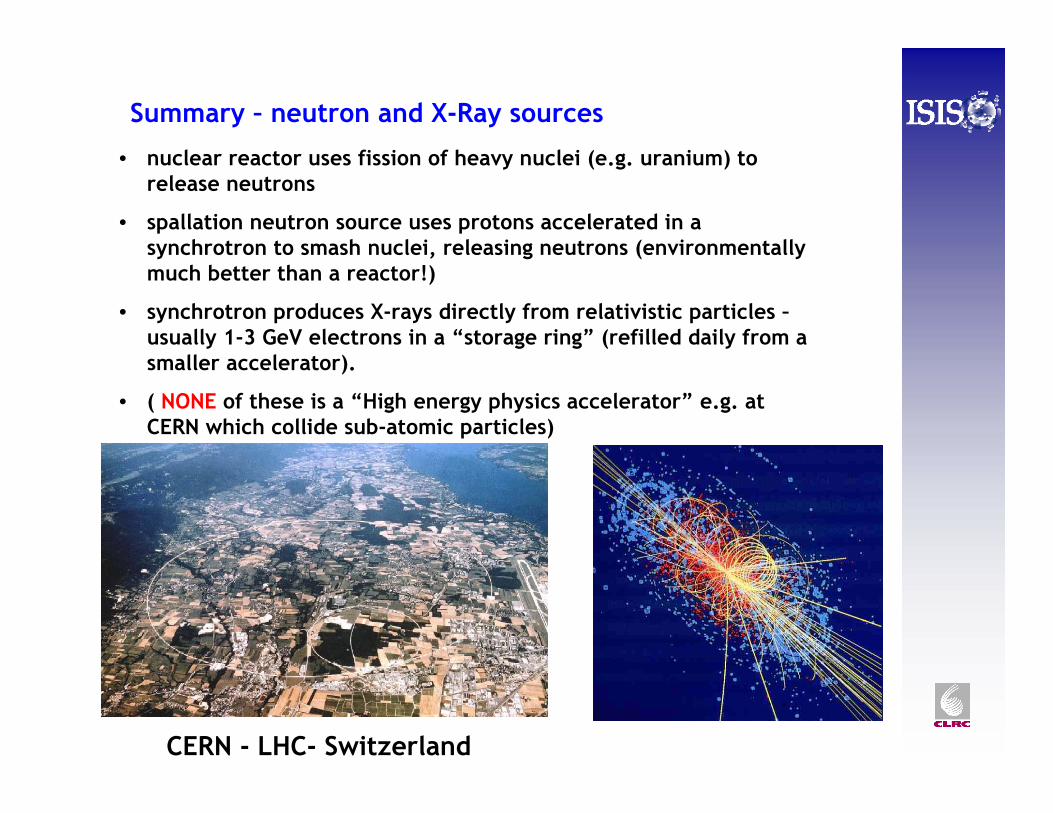
• nuclear reactor uses fission of heavy nuclei (e.g. uranium) to release neutrons
• spallation neutron source uses protons accelerated in a synchrotron to smash nuclei, releasing neutrons (environmentallymuch better than a reactor!)
• synchrotron produces X-rays directly from relativistic particles –usually 1-3 GeV electrons in a “storage ring” (refilled daily from a smaller accelerator).
• ( NONE of these is a “High energy physics accelerator” e.g. at CERN which collide sub-atomic particles)
Summary – neutron and X-Ray sources
CERN - LHC- Switzerland
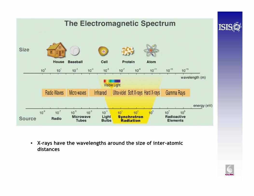
• X-rays have the wavelengths around the size of inter-atomic distances
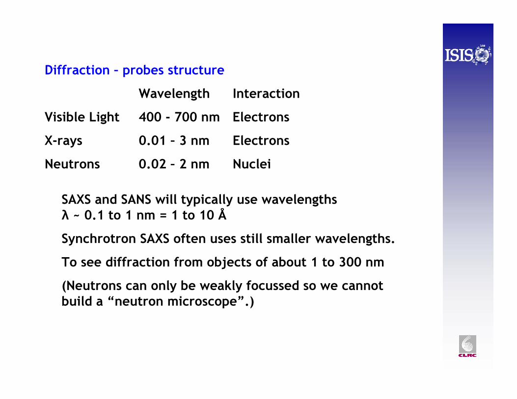
Why Use Neutrons? - IDiffraction – probes structure
Wavelength Interaction
Visible Light 400 - 700 nm Electrons
X-rays 0.01 – 3 nm Electrons
Neutrons 0.02 – 2 nm Nuclei
SAXS and SANS will typically use wavelengths λ ~ 0.1 to 1 nm = 1 to 10 Å
Synchrotron SAXS often uses still smaller wavelengths.
To see diffraction from objects of about 1 to 300 nm
(Neutrons can only be weakly focussed so we cannot build a “neutron microscope”.)
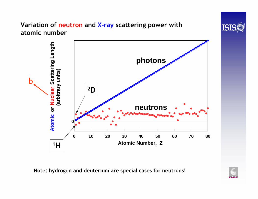
Scattering LengthsVariation of neutron and X-ray scattering power with atomic number
0 10 20 30 40 50 60 70 80Atomic Number, Z
-10Ato
mic
or
Nuc
lear
Sca
tterin
g Le
ngth
(ar
bitr
ary
units
)photons
neutrons
b
0
1H
2D
Note: hydrogen and deuterium are special cases for neutrons!
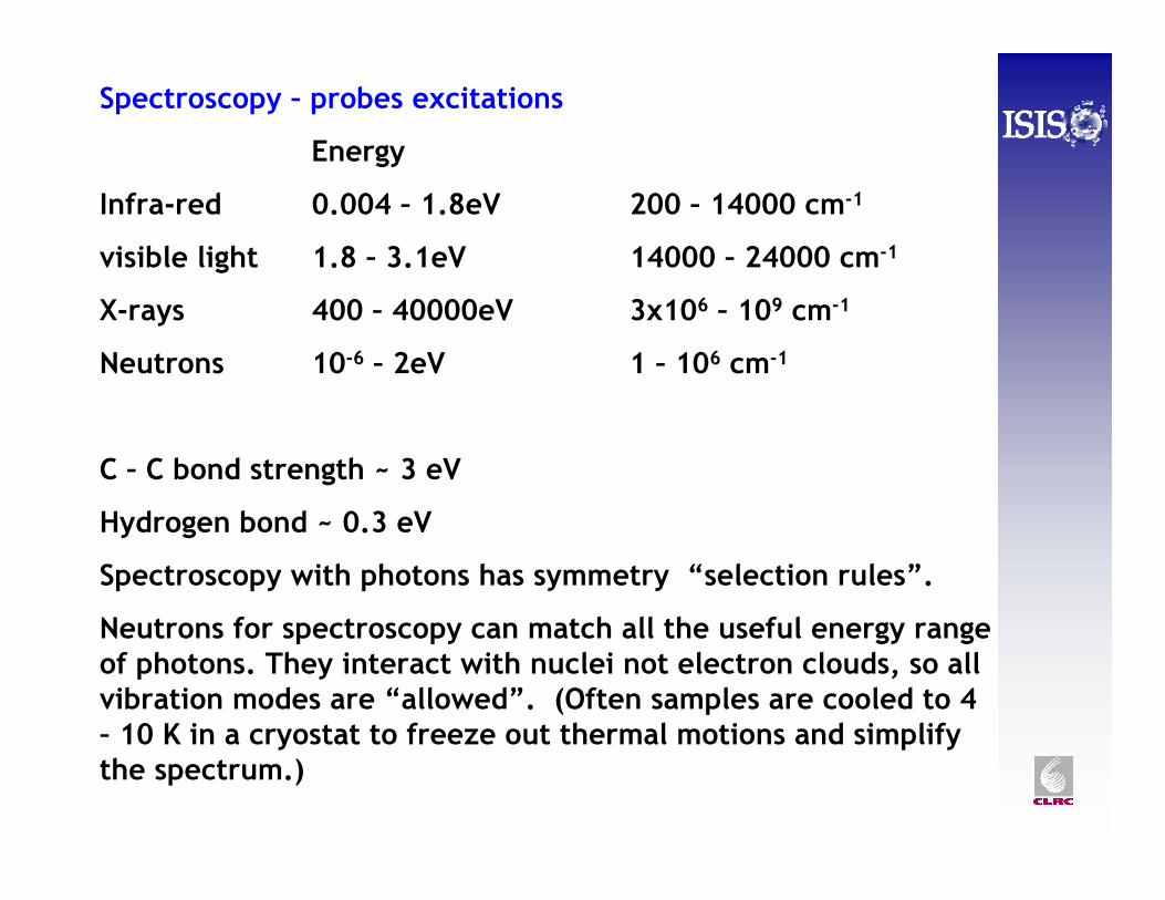
Why Use Neutrons? - IISpectroscopy – probes excitations
Energy
Infra-red 0.004 – 1.8eV 200 – 14000 cm-1
visible light 1.8 – 3.1eV 14000 – 24000 cm-1
X-rays 400 – 40000eV 3x10⁶ – 109 cm-1
Neutrons 10-6 – 2eV 1 – 106 cm-1
C – C bond strength ~ 3 eV
Hydrogen bond ~ 0.3 eV
Spectroscopy with photons has symmetry “selection rules”.
Neutrons for spectroscopy can match all the useful energy range of photons. They interact with nuclei not electron clouds, so all vibration modes are “allowed”. (Often samples are cooled to 4 – 10 K in a cryostat to freeze out thermal motions and simplify the spectrum.)
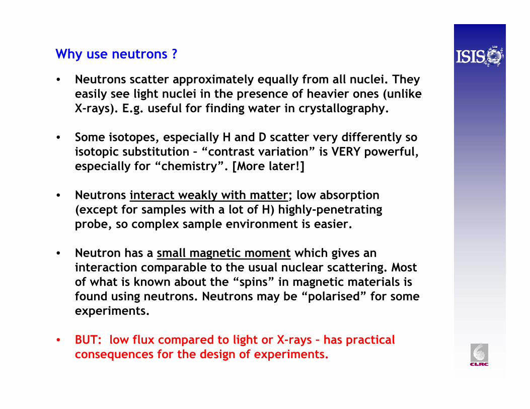
Why use neutrons ?
• Neutrons scatter approximately equally from all nuclei. They easily see light nuclei in the presence of heavier ones (unlike X-rays). E.g. useful for finding water in crystallography.
• Some isotopes, especially H and D scatter very differently so isotopic substitution – “contrast variation” is VERY powerful, especially for “chemistry”. [More later!]
• Neutrons interact weakly with matter; low absorption (except for samples with a lot of H) highly-penetrating probe, so complex sample environment is easier.
• Neutron has a small magnetic moment which gives an interaction comparable to the usual nuclear scattering. Most of what is known about the “spins” in magnetic materials is found using neutrons. Neutrons may be “polarised” for some experiments.
• BUT: low flux compared to light or X-rays – has practical consequences for the design of experiments.
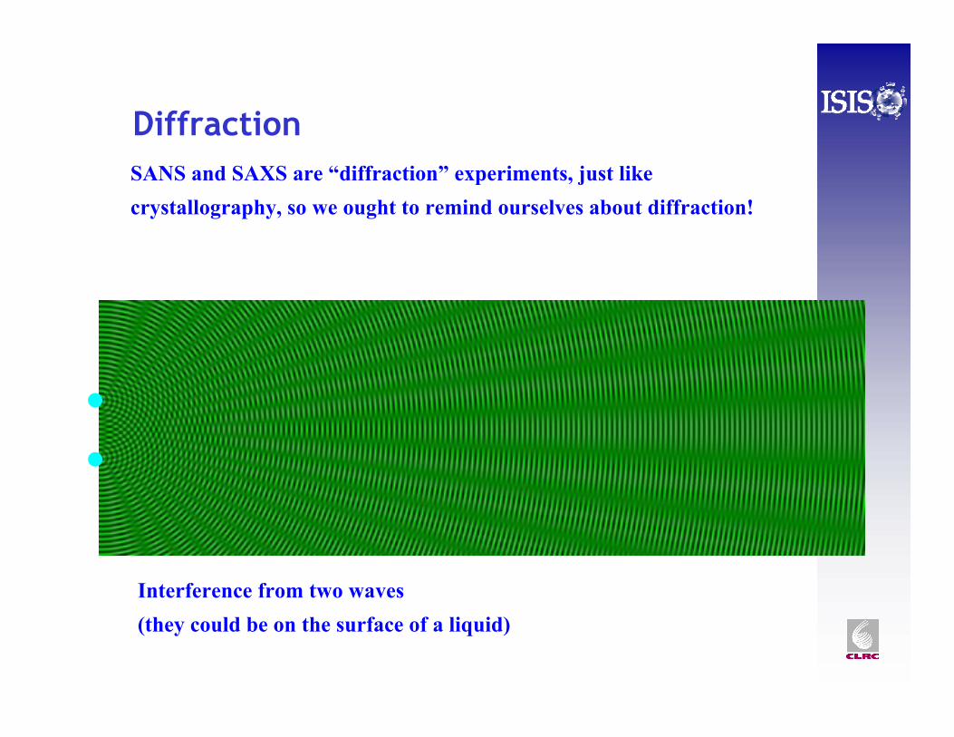
Diffraction
Interference from two waves (they could be on the surface of a liquid)
SANS and SAXS are “diffraction” experiments, just like crystallography, so we ought to remind ourselves about diffraction!
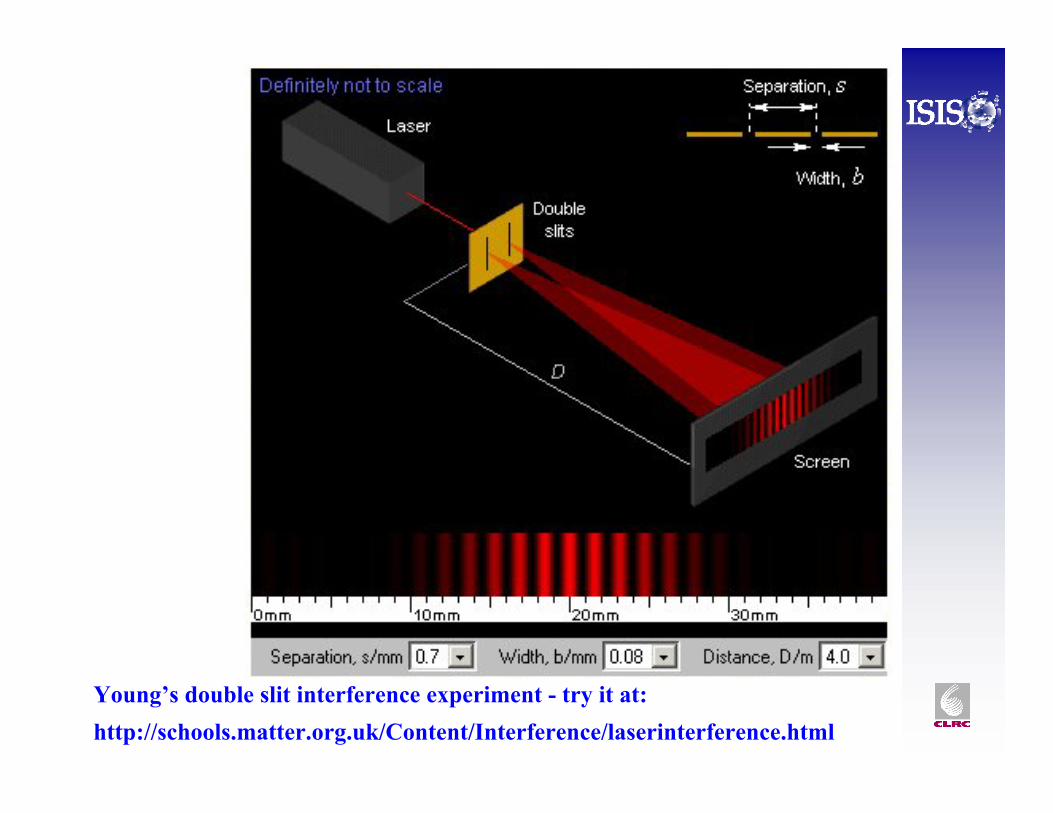
Young’s double slit interference experiment - try it at: http://schools.matter.org.uk/Content/Interference/laserinterference.html
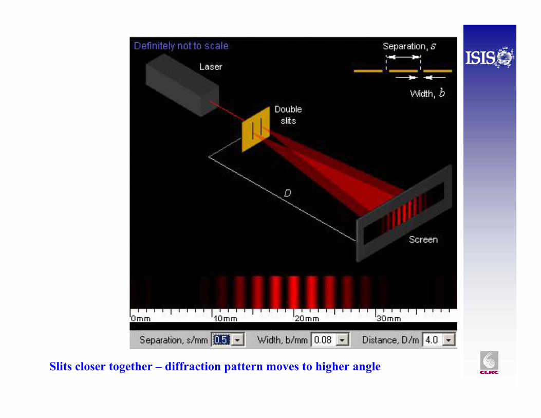
Slits closer together – diffraction pattern moves to higher angle
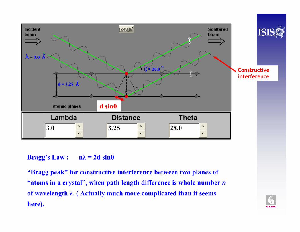
Bragg’s Law : nλ = 2d sinθ
“Bragg peak” for constructive interference between two planes of “atoms in a crystal”, when path length difference is whole number n of wavelength λ. ( Actually much more complicated than it seems here).
Constructive interference
d sinθ
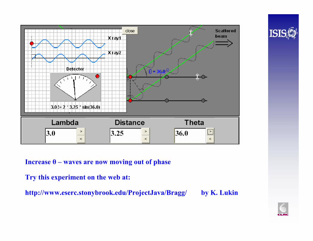
Increase θ – waves are now moving out of phase
Try this experiment on the web at:
http://www.eserc.stonybrook.edu/ProjectJava/Bragg/ by K. Lukin
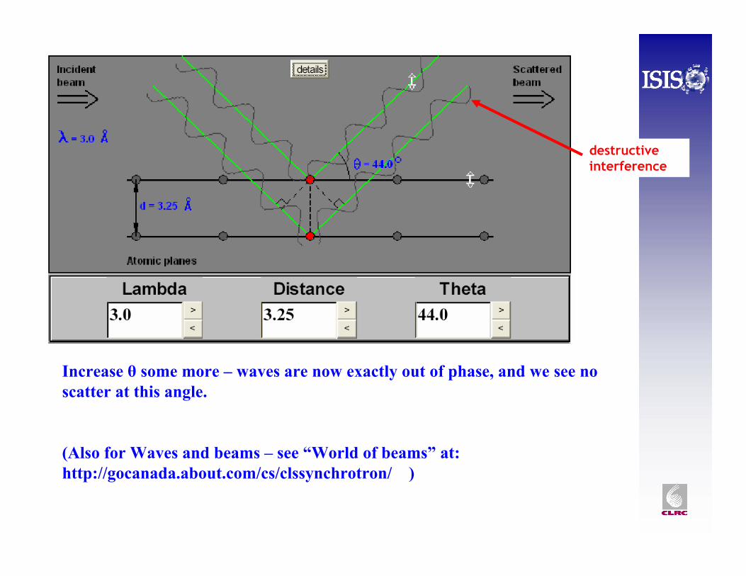
Increase θ some more – waves are now exactly out of phase, and we see no scatter at this angle.
(Also for Waves and beams – see “World of beams” at:http://gocanada.about.com/cs/clssynchrotron/ )
destructive interference
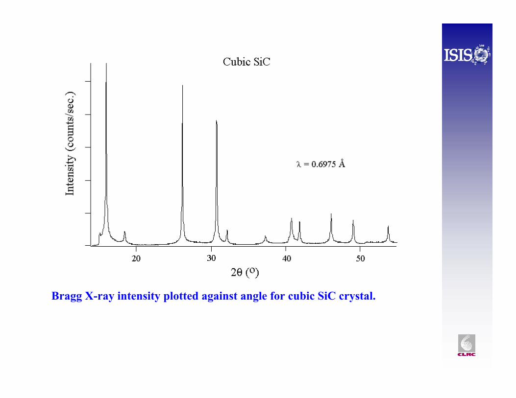
Bragg X-ray intensity plotted against angle for cubic SiC crystal.
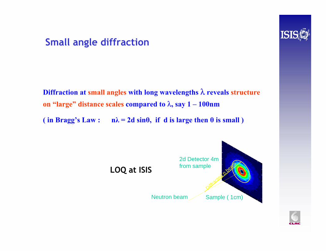
Small angle diffraction
Diffraction at small angles with long wavelengths λ reveals structure on “large” distance scales compared to λ, say 1 – 100nm
( in Bragg’s Law : nλ = 2d sinθ, if d is large then θ is small )
Diffrac
ted n
beam
2d Detector 4m from sample
Sample ( 1cm)Neutron beam
LOQ at ISIS
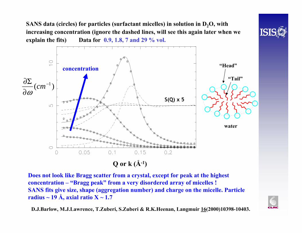
SANS data (circles) for particles (surfactant micelles) in solution in D2O, with increasing concentration (ignore the dashed lines, will see this again later when we explain the fits) Data for 0.9, 1.8, 7 and 29 % vol.
D.J.Barlow, M.J.Lawrence, T.Zuberi, S.Zuberi & R.K.Heenan, Langmuir 16(2000)10398-10403.
Does not look like Bragg scatter from a crystal, except for peak at the highest concentration – “Bragg peak” from a very disordered array of micelles ! SANS fits give size, shape (aggregation number) and charge on the micelle. Particle radius ~ 19 Å, axial ratio X ~ 1.7
“Head”
water
“Tail”
concentration
Q or k (Å-1)
)( 1−
∂Σ∂ cmω
S(Q) x 5
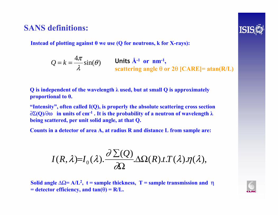
SANS definitions:
)sin(4 θλπ== kQ Units Å-1 or nm-1,
scattering angle θ or 2θ [CARE]= atan(R/L)
),().(.).(.)().(),( 0 ληλ∂
∂λλ TtRQIRI ΔΩΩ∑=
Q is independent of the wavelength λ used, but at small Q is approximately proportional to θ.
“Intensity”, often called I(Q), is properly the absolute scattering cross section ∂Σ(Q)/∂ω in units of cm-1 . It is the probability of a neutron of wavelength λbeing scattered, per unit solid angle, at that Q.
Counts in a detector of area A, at radius R and distance L from sample are:
Solid angle ΔΩ= A/L2, t = sample thickness, T = sample transmission and η= detector efficiency, and tan(θ) = R/L.
Instead of plotting against θ we use (Q for neutrons, k for X-rays):
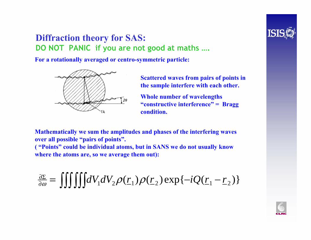
Diffraction theory for SAS: DO NOT PANIC if you are not good at maths ….
Mathematically we sum the amplitudes and phases of the interfering waves over all possible “pairs of points”. ( “Points” could be individual atoms, but in SANS we do not usually know where the atoms are, so we average them out):
For a rotationally averaged or centro-symmetric particle:
Scattered waves from pairs of points in the sample interfere with each other.
Whole number of wavelengths “constructive interference” = Bragg condition.
)}(exp{)()( 212121 rriQrrdVdV −−= ∫∫∫∫∫∫∂Σ∂ ρρω
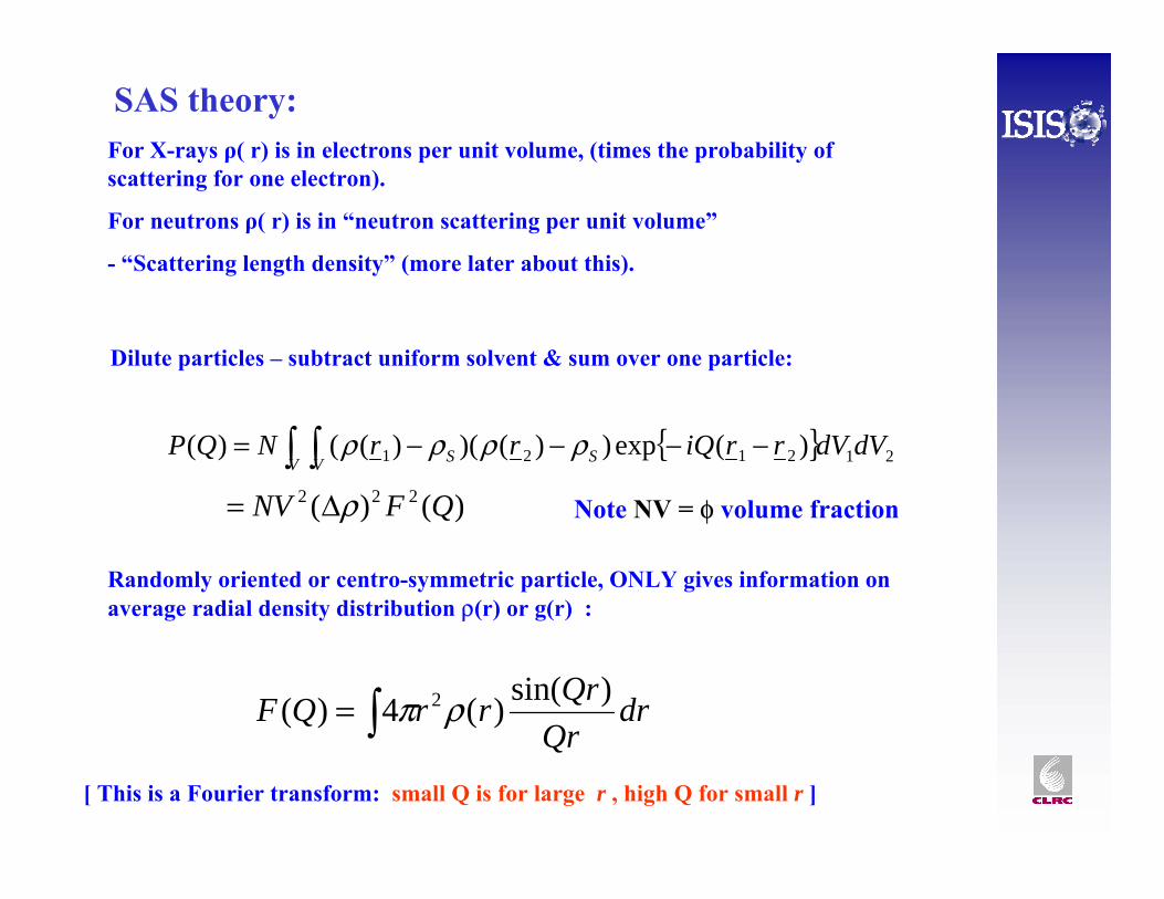
SAS theory:
{ } 212121 )(exp))()()(()( dVdVrriQrrNQPV V SS∫ ∫ −−−−= ρρρρ
)()( 222 QFNV ρΔ=
∫= drQr
QrrrQF )sin()(4)( 2ρπ
Randomly oriented or centro-symmetric particle, ONLY gives information on average radial density distribution ρ(r) or g(r) :
Dilute particles – subtract uniform solvent & sum over one particle:
Note NV = φ volume fraction
[ This is a Fourier transform: small Q is for large r , high Q for small r ]
For X-rays ρ( r) is in electrons per unit volume, (times the probability of scattering for one electron).
For neutrons ρ( r) is in “neutron scattering per unit volume”
- “Scattering length density” (more later about this).
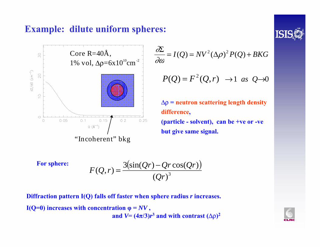
Core R=40Å,1% vol, Δρ=6x1010cm -2
“Incoherent” bkg
Example: dilute uniform spheres:
BKGQPNVQI +Δ==Σ )()()( 22 ρ∂ω∂
),()( 2 rQFQP =
( )3)(
)cos()sin(3),(Qr
QrQrQrrQF −=
01 →→ Qas
For sphere:
Δρ = neutron scattering length density difference, (particle - solvent), can be +ve or -vebut give same signal.
Diffraction pattern I(Q) falls off faster when sphere radius r increases.
I(Q=0) increases with concentration φ = NV ,and V= (4π/3)r3 and with contrast (Δρ)2
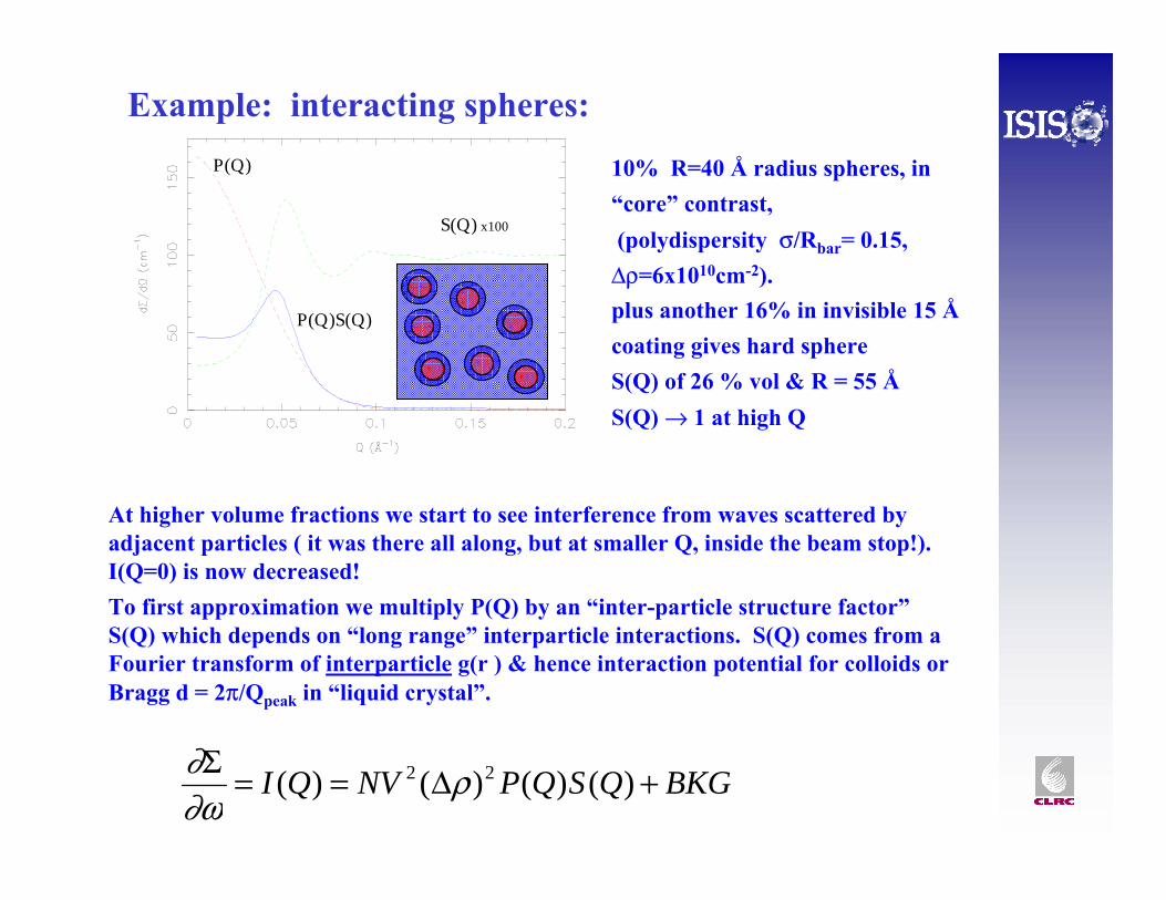
S(Q) x100
P(Q)
P(Q)S(Q)
Example: interacting spheres:
10% R=40 Å radius spheres, in “core” contrast, (polydispersity σ/Rbar= 0.15,
Δρ=6x1010cm-2). plus another 16% in invisible 15 Åcoating gives hard sphereS(Q) of 26 % vol & R = 55 ÅS(Q) → 1 at high Q
BKGQSQPNVQI +Δ==Σ )()()()( 22 ρ∂ω∂
At higher volume fractions we start to see interference from waves scattered by adjacent particles ( it was there all along, but at smaller Q, inside the beam stop!). I(Q=0) is now decreased!To first approximation we multiply P(Q) by an “inter-particle structure factor”S(Q) which depends on “long range” interparticle interactions. S(Q) comes from a Fourier transform of interparticle g(r ) & hence interaction potential for colloids or Bragg d = 2π/Qpeak in “liquid crystal”.

What SANS ( & SAXS) tells us ...
• Nanostructure (size, shape)• Internal features (contrast
variation)• Molecular weight - aggregation
number• Surface/volume (Porod)• Interactions (hard, soft, charged)• Location of components (contrast
variation, interfaces)• Relation to microstructure (porous
solids etc.)
Dilute particles
Concentrated systems
We always learn something ….
SANS science includes:
•Biomolecular solutions -protein conformation
•Membranes, vesicles
•Porous materials, voids in metals
•Phase separation
•Liquid crystals
•Magnetic scattering
•Alloy structure
•Fractal dimensions
•Nature of surfaces
•Surfactant micelles, structure & interaction potentials
•Microemulsion droplets - contrast variation for structure & composition
•Block copolymer micelle - size & density profile.
•Polymer solutions
•Polymer/surfactant interaction.
•Bulk (melt or solid) polymers, using H-D contrast
•Polymer density profile (interfaces large droplets)

Please pay attention …
• The PRINCIPLES of scattering or diffraction are the SAME for many different subject areas.
• If I give an example from surfactant science the same ideas will often work for proteins, liquid crystals, polymers, phase separated metal alloys or whatever nanoscale materials you are interested in!
• There will not be time to include examples of every scientific possibility – you are WELCOME to discuss your science with me after the lectures.
• For more details you will need to read the scientific literature and (rare) text books.
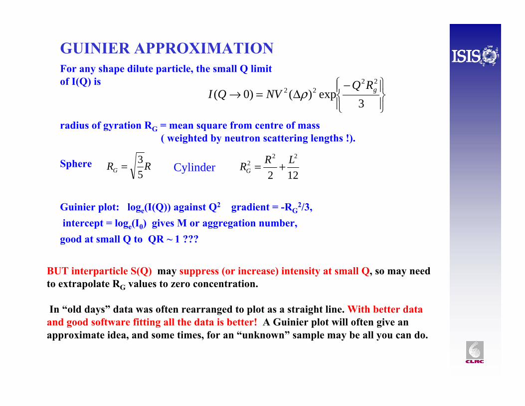
For any shape dilute particle, the small Q limit of I(Q) is
radius of gyration RG = mean square from centre of mass ( weighted by neutron scattering lengths !).
Sphere
GUINIER APPROXIMATION
⎪⎭
⎪⎬⎫
⎪⎩
⎪⎨⎧−
Δ=→3
exp)()0(22
22 gRQNVQI ρ
RRG 53=
122
222 LRRG +=
Guinier plot: loge(I(Q)) against Q2 gradient = -RG2/3,
intercept = loge(I0) gives M or aggregation number, good at small Q to QR ~ 1 ???
BUT interparticle S(Q) may suppress (or increase) intensity at small Q, so may need to extrapolate RG values to zero concentration.
In “old days” data was often rearranged to plot as a straight line. With better data and good software fitting all the data is better! A Guinier plot will often give an approximate idea, and some times, for an “unknown” sample may be all you can do.
Cylinder
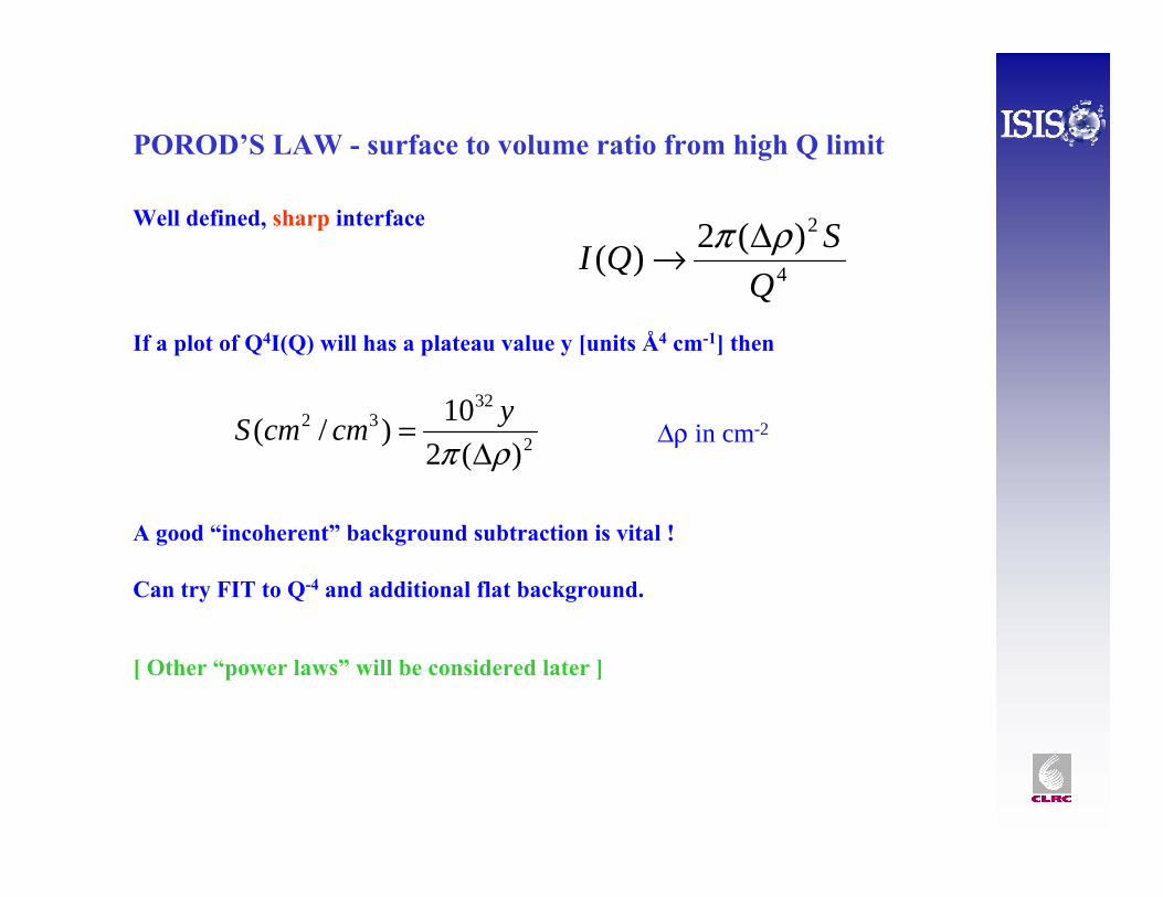
Well defined, sharp interface
If a plot of Q4I(Q) will has a plateau value y [units Å4 cm-1] then
POROD’S LAW - surface to volume ratio from high Q limit
A good “incoherent” background subtraction is vital !
Can try FIT to Q-4 and additional flat background.
[ Other “power laws” will be considered later ]
Δρ in cm-2
4
2)(2)(Q
SQI ρπ Δ→
2
3232
)(210)/(
ρπ Δ= ycmcmS
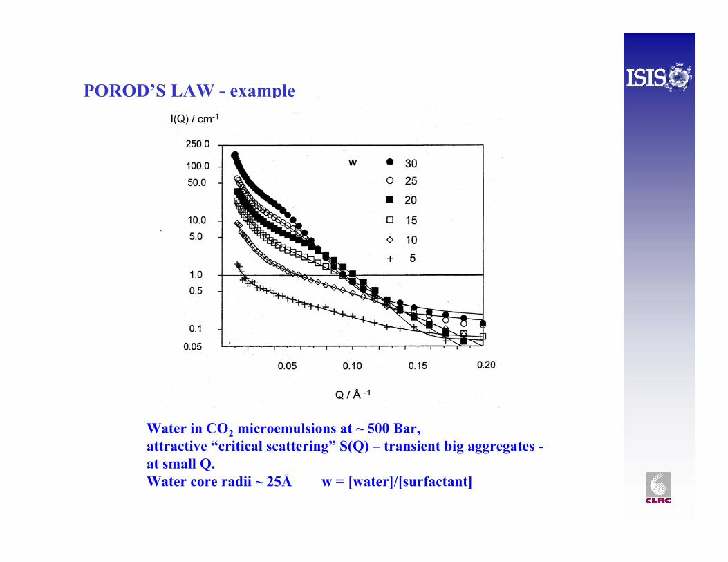
POROD’S LAW - example
Water in CO2 microemulsions at ~ 500 Bar, attractive “critical scattering” S(Q) – transient big aggregates -at small Q. Water core radii ~ 25Å w = [water]/[surfactant]
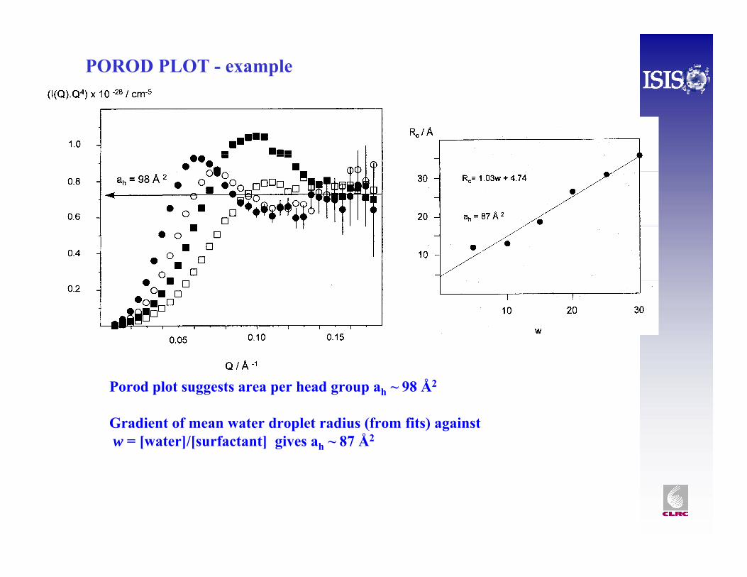
POROD PLOT - example
Porod plot suggests area per head group ah ~ 98 Å2
Gradient of mean water droplet radius (from fits) againstw = [water]/[surfactant] gives ah ~ 87 Å2
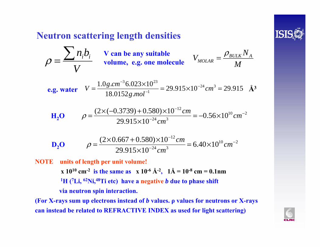
Neutron scattering length densities
Vbn ii∑=ρ
V can be any suitable volume, e.g. one molecule M
NV ABULKMOLAR
ρ=
915.2910915.29.0152.18
10023.6.0.1 3241
233
=×=×= −−
−
cmmolg
cmgVe.g. water Å3
210324
12
1040.610915.29
10)580.0667.02( −−
−
×=×
×+×= cmcm
cmρD2O
210324
12
1056.010915.29
10)580.0)3739.0(2( −−
−
×−=×
×+−×= cmcm
cmρH2O
NOTE units of length per unit volume!x 1010 cm-2 is the same as x 10-6 Å-2, 1Å = 10-8 cm = 0.1nm 1H (7Li, 62Ni,48Ti etc) have a negative b due to phase shift via neutron spin interaction.
(For X-rays sum up electrons instead of b values. ρ values for neutrons or X-rays can instead be related to REFRACTIVE INDEX as used for light scattering)
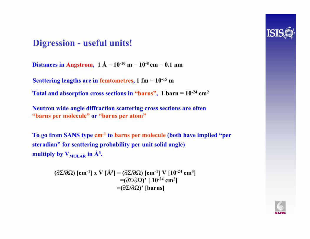
Distances in Angstrom, 1 Å = 10-10 m = 10-8 cm = 0.1 nm
Digression - useful units!
Scattering lengths are in femtometres, 1 fm = 10-15 m
Total and absorption cross sections in “barns”, 1 barn = 10-24 cm2
Neutron wide angle diffraction scattering cross sections are often“barns per molecule” or “barns per atom”
To go from SANS type cm-1 to barns per molecule (both have implied “per steradian” for scattering probability per unit solid angle) multiply by VMOLAR in Å3.
(∂Σ/∂Ω) [cm-1] x V [Å3] = (∂Σ/∂Ω) [cm-1] V [10-24 cm3] =(∂Σ/∂Ω)’ [ 10-24 cm2]
=(∂Σ/∂Ω)’ [barns]
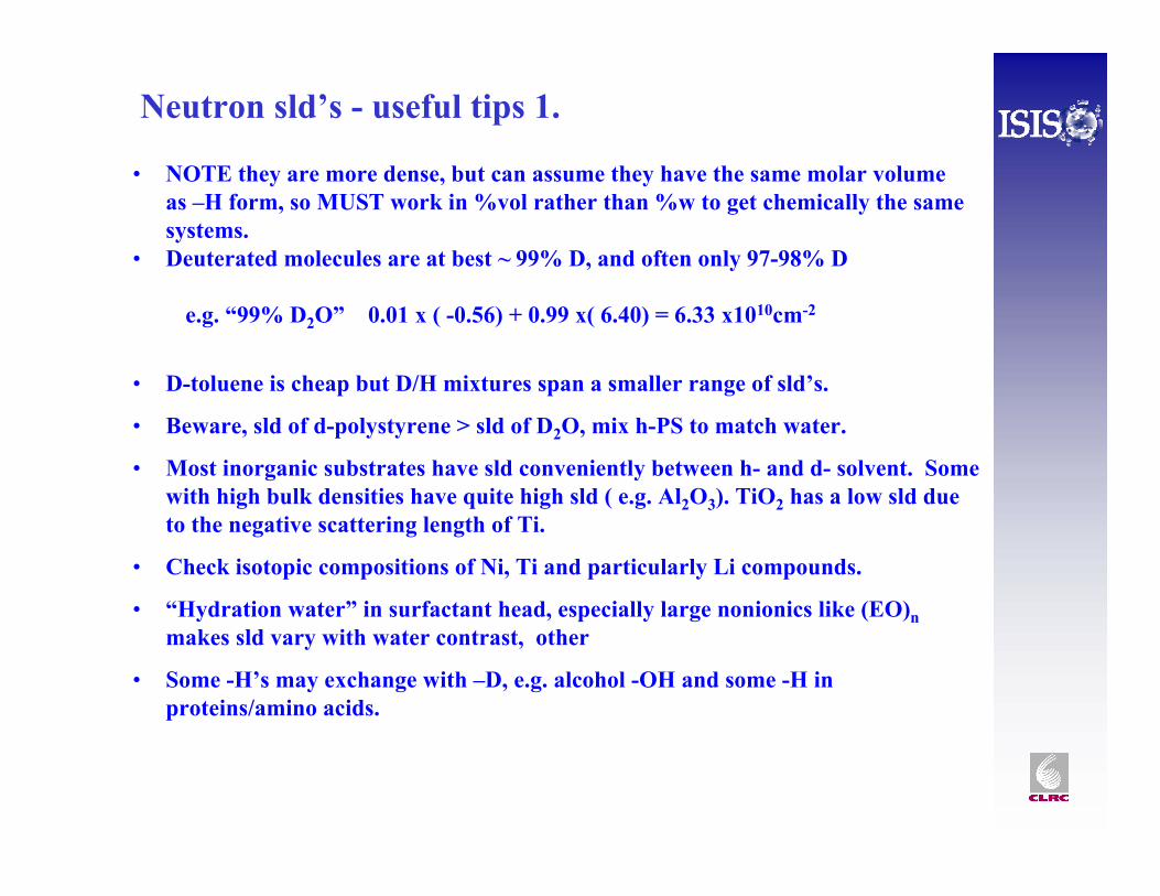
• NOTE they are more dense, but can assume they have the same molar volume as –H form, so MUST work in %vol rather than %w to get chemically the same systems.
• Deuterated molecules are at best ~ 99% D, and often only 97-98% D
e.g. “99% D2O” 0.01 x ( -0.56) + 0.99 x( 6.40) = 6.33 x1010cm-2
Neutron sld’s - useful tips 1.
• D-toluene is cheap but D/H mixtures span a smaller range of sld’s.
• Beware, sld of d-polystyrene > sld of D2O, mix h-PS to match water.
• Most inorganic substrates have sld conveniently between h- and d- solvent. Some with high bulk densities have quite high sld ( e.g. Al2O3). TiO2 has a low sld due to the negative scattering length of Ti.
• Check isotopic compositions of Ni, Ti and particularly Li compounds.
• “Hydration water” in surfactant head, especially large nonionics like (EO)nmakes sld vary with water contrast, other
• Some -H’s may exchange with –D, e.g. alcohol -OH and some -H in proteins/amino acids.
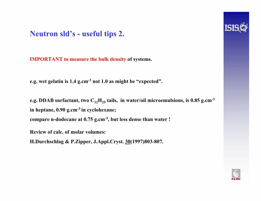
Neutron sld’s - useful tips 2.
IMPORTANT to measure the bulk density of systems.
e.g. wet gelatin is 1.4 g.cm-3 not 1.0 as might be “expected”.
e.g. DDAB surfactant, two C12H25 tails, in water/oil microemulsions, is 0.85 g.cm-3
in heptane, 0.90 g.cm-3 in cyclohexane;
compare n-dodecane at 0.75 g.cm-3, but less dense than water !
Review of calc. of molar volumes:
H.Durchschlag & P.Zipper, J.Appl.Cryst. 30(1997)803-807.
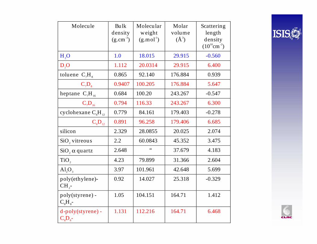
Molecule Bulkdensity(g.cm -3)
Molecularweight
(g.mol-1)
Molarvolume
(Å3)
Scatteringlengthdensity
(1010cm -2)
H 2O 1.0 18.015 29.915 -0.560
D2O 1.112 20.0314 29.915 6.400
toluene C7H 8 0.865 92.140 176.884 0.939
C7D8 0.9407 100.205 176.884 5.647
heptane C7H 16 0.684 100.20 243.267 -0.547
C7D16 0.794 116.33 243.267 6.300
cyclohexane C6H 12 0.779 84.161 179.403 -0.278
C6D12 0.891 96.258 179.406 6.685
silicon 2.329 28.0855 20.025 2.074
SiO2 vitreous 2.2 60.0843 45.352 3.475
SiO2 α quartz 2.648 “ 37.679 4.183
TiO2 4.23 79.899 31.366 2.604
Al2O3 3.97 101.961 42.648 5.699
poly(ethylene)-CH 2-
0.92 14.027 25.318 -0.329
poly(styrene) -C8H 8-
1.05 104.151 164.71 1.412
d-poly(styrene) -C8D8-
1.131 112.216 164.71 6.468
R
sld
R1
ρ1
R2
ρ2
ρ3
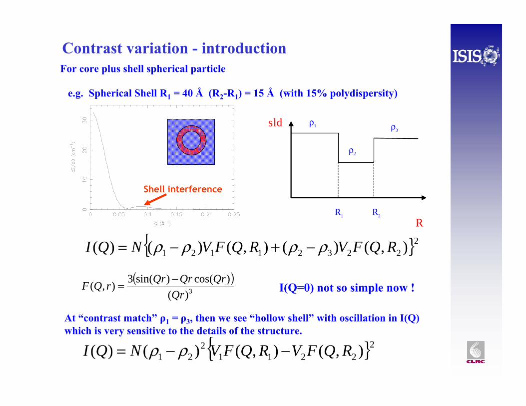
e.g. Spherical Shell R1 = 40 Å (R2-R1) = 15 Å (with 15% polydispersity)
Contrast variation - introduction
}{ 222321121 ),()(),()()( RQFVRQFVNQI ρρρρ −+−=
( )3)(
)cos()sin(3),(Qr
QrQrQrrQF −= I(Q=0) not so simple now !
For core plus shell spherical particle
At “contrast match” ρ1 = ρ3, then we see “hollow shell” with oscillation in I(Q) which is very sensitive to the details of the structure.
}{ 22211
221 ),(),()()( RQFVRQFVNQI −−= ρρ
Shell interference
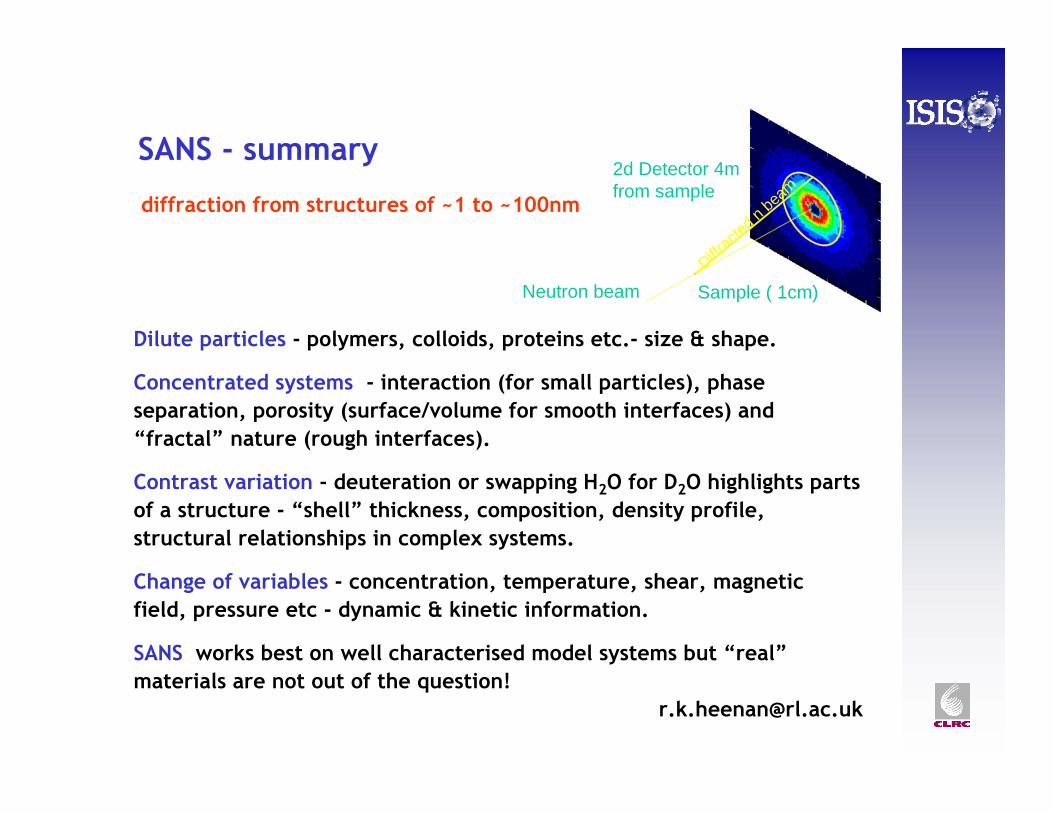
SANS - summary
diffraction from structures of ~1 to ~100nm
Dilute particles - polymers, colloids, proteins etc.- size & shape.
Concentrated systems - interaction (for small particles), phase separation, porosity (surface/volume for smooth interfaces) and “fractal” nature (rough interfaces).
Contrast variation - deuteration or swapping H2O for D2O highlights parts of a structure - “shell” thickness, composition, density profile, structural relationships in complex systems.
Change of variables - concentration, temperature, shear, magnetic field, pressure etc - dynamic & kinetic information.
SANS works best on well characterised model systems but “real”materials are not out of the question!
Diffrac
ted n
beam
2d Detector 4m from sample
Sample ( 1cm)Neutron beam
How to do a SANS experiment
NEXT :