Embed Size (px)
Citation preview
Small Autonomous Robot Actuator (SARA): A Solar-
powered Wireless MEMS Gripper
Alexis Moreno
Electrical Engineering and Computer SciencesUniversity of California, Berkeley
Technical Report No. UCB/EECS-2021-129
http://www2.eecs.berkeley.edu/Pubs/TechRpts/2021/EECS-2021-129.html
May 14, 2021

Copyright © 2021, by the author(s).All rights reserved.
Permission to make digital or hard copies of all or part of this work forpersonal or classroom use is granted without fee provided that copies arenot made or distributed for profit or commercial advantage and that copiesbear this notice and the full citation on the first page. To copy otherwise, torepublish, to post on servers or to redistribute to lists, requires prior specificpermission.
Small Autonomous Robot Actuator (SARA): A Solar-powered Wireless MEMS Gripper
by Alex Moreno
Research Project
Submitted to the Department of Electrical Engineering and Computer Sciences, University of California at Berkeley, in partial satisfaction of the requirements for the degree of Master of Science, Plan II. Approval for the Report and Comprehensive Examination:
Committee:
Professor Kristofer S.J. Pister Research Advisor
(Date)
* * * * * * *
Professor Ali M. Niknejad Second Reader
(Date)
Small Autonomous Robot Actuator (SARA): A Solar-powered Wireless MEMS Gripper
by
Alex Moreno
A thesis submitted in partial satisfaction of the
requirements for the degree of
Master of Science
in
Engineering – Electrical Engineering and Computer Sciences
in the
Graduate Division
of the
University of California, Berkeley
Committee in charge:
Professor Kristofer S.J. Pister, ChairProfessor Ali M. Niknejad, Co-chair
Spring 2021
Small Autonomous Robot Actuator (SARA): A Solar-powered Wireless MEMS Gripper
Copyright 2021by
Alex Moreno
1
Abstract
Small Autonomous Robot Actuator (SARA): A Solar-powered Wireless MEMS Gripper
by
Alex Moreno
Master of Science in Engineering – Electrical Engineering and Computer Sciences
University of California, Berkeley
Professor Kristofer S.J. Pister, Chair
Professor Ali M. Niknejad, Co-chair
Solar-powered actuation of a 15 mN electrostatic MEMS gripper was demonstrated whilewirelessly triggered by IEEE 802.15.4 RF signals. The solar-powered gripper was shownto actuate at a rate of 640 um/s. The complete system is composed of three capacitorsand three chips: MEMS gripper, microprocessor/crystal-free radio, and solar cell array/highvoltage buffer. Control signals for the electrostatic inchworm motors originate from the3×2×0.3 mm3 chip with an ARM Cortex-M0 microprocessor and are passed through 119 Vhigh voltage buffers. Power for all components, including the crystal-free radio, micropro-cessor, and 119 V buffers, is supplied by a multi-output array of solar cells on a CMOS SOIchip under 200 mW/cm2 irradiation.

i
Para mi mama, Sara.
Gracias por tu apoyo constante y determinacion para darnos la educacion que no pudistetener.
To my mom, Sara.
Thank you for your constant support and determination to give us the education you werenot able to have.
ii
Contents
Contents ii
List of Figures iii
List of Tables iv
1 Introduction 1
2 System Description 42.1 SCµM: Crystal-Free Radio and Microprocessor . . . . . . . . . . . . . . . . . 42.2 Zappy 2: Solar Cell and High Voltage Buffers . . . . . . . . . . . . . . . . . 52.3 Gripper: MEMS SOI 15 mN Gripper . . . . . . . . . . . . . . . . . . . . . . 6
3 System Operation 83.1 Phase 1: Optical Calibration . . . . . . . . . . . . . . . . . . . . . . . . . . . 83.2 Phase 2: Solar Power and LC Calibration . . . . . . . . . . . . . . . . . . . . 83.3 Phase 3: Receive Packets . . . . . . . . . . . . . . . . . . . . . . . . . . . . . 93.4 Phase 4: Transmit acknowledgement . . . . . . . . . . . . . . . . . . . . . . 103.5 Phase 5: MEMS Gripper Actuation . . . . . . . . . . . . . . . . . . . . . . . 11
4 Conclusion 16
Bibliography 17
iii
List of Figures
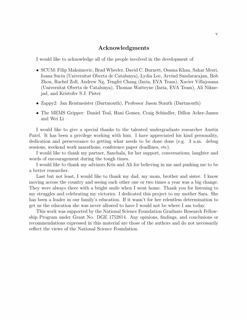
1.1 MEMS Gripper, HV Buffer & Solar Cell Array Chip, Single Chip Micro Mote(left to right). Two SCµM chips are stacked due to initial SCµM malfunctioning.The dimensions of SARA are 9.5×31.55 mm2 . . . . . . . . . . . . . . . . . . . . 2
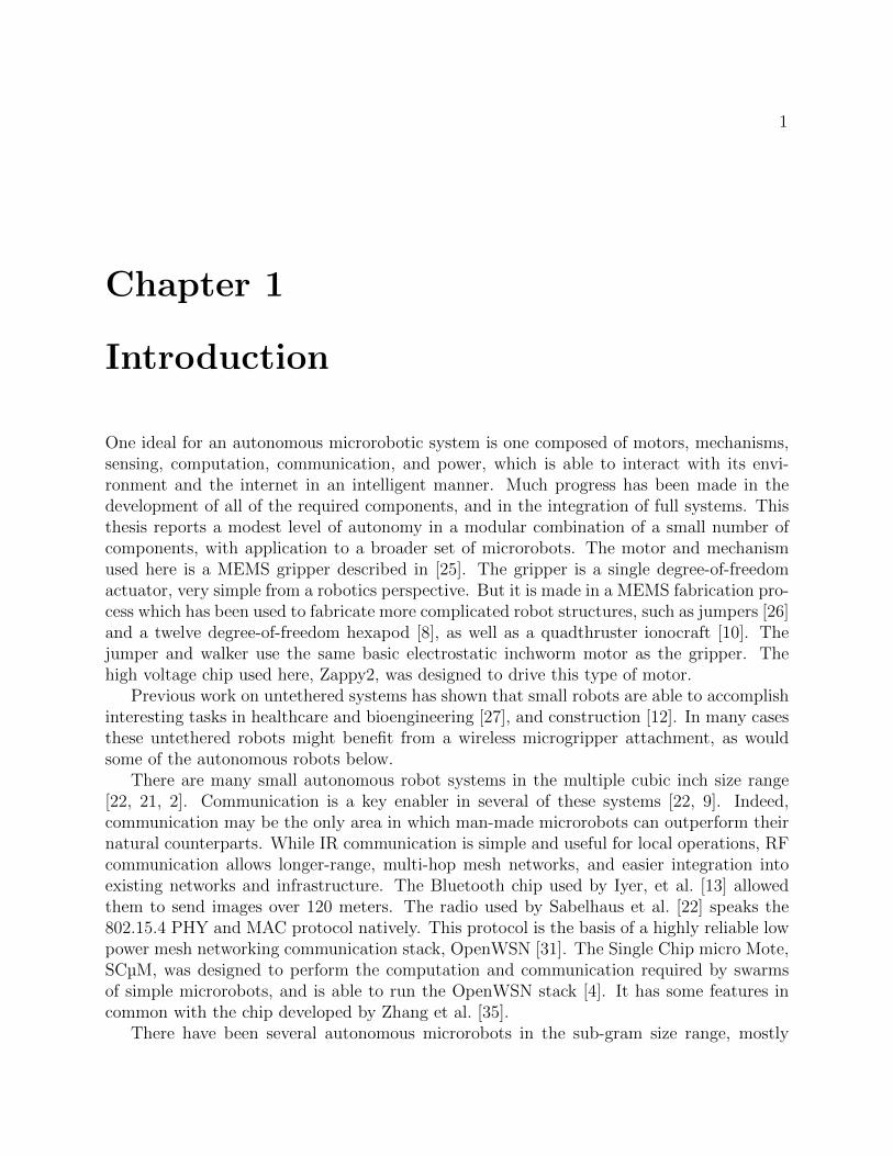
1.2 System block diagram including power domains, phases of operation, and allcomponents. . . . . . . . . . . . . . . . . . . . . . . . . . . . . . . . . . . . . . . 3
2.1 Model used to maintain proper operating voltages and functionality of SARA.Typically Iquiescent=350 µA and Itransient=1250 µA during radio operation. . . . . 6
3.1 Crystal-free radio local oscillator frequency vs. VBAT voltage at a fixed LCtuning setting. The blue lines shows the ±40 ppm tolerance band of the 802.15.4standard and the green lines shows the ±150 ppm tolerance of the OpenMote. . 10
3.2 VBAT current during wireless 802.15.4 receive (200 mW/cm2 irradiation; 47 µFVBAT bypass capacitor). φ1: Low power (Fcortex=78 kHz), φ2: RX with radioon, φ3: periodic wake up to Fcortex=5 MHz . . . . . . . . . . . . . . . . . . . . . 11
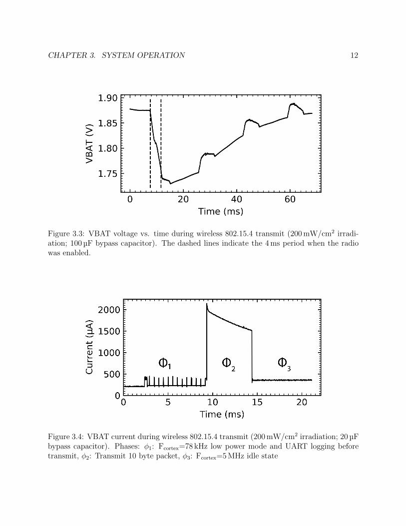
3.3 VBAT voltage vs. time during wireless 802.15.4 transmit (200 mW/cm2 irradia-tion; 100 µF bypass capacitor). The dashed lines indicate the 4 ms period whenthe radio was enabled. . . . . . . . . . . . . . . . . . . . . . . . . . . . . . . . . 12
3.4 VBAT current during wireless 802.15.4 transmit (200 mW/cm2 irradiation; 20 µFbypass capacitor). Phases: φ1: Fcortex=78 kHz low power mode and UART log-ging before transmit, φ2: Transmit 10 byte packet, φ3: Fcortex=5 MHz idle state 12
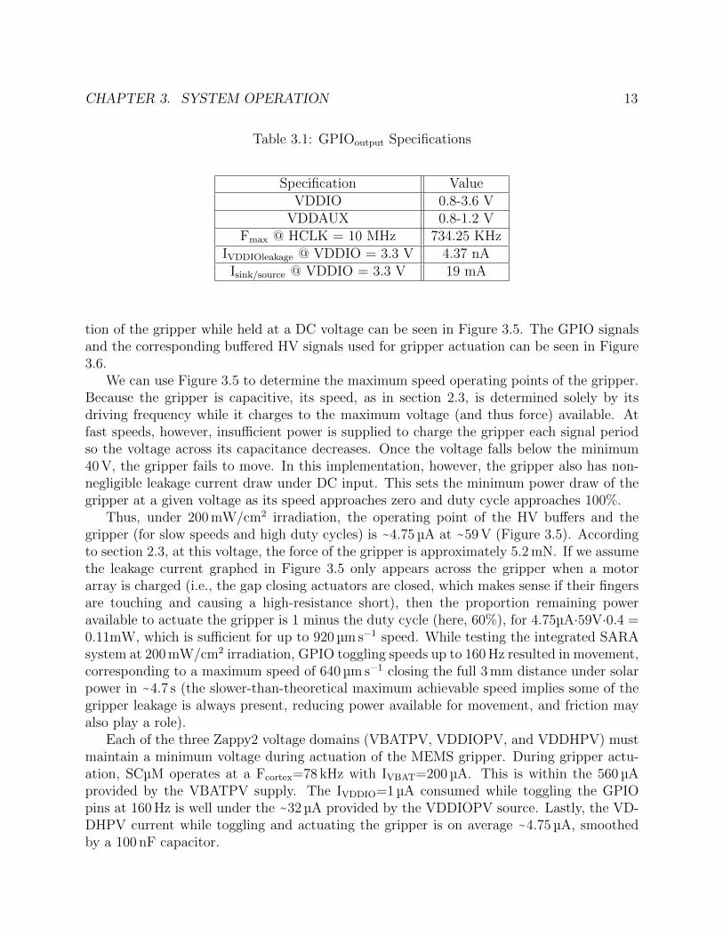
3.5 Measured gripper leakage current under DC supply vs. HV buffer DC voltage,and Zappy2 VDDHPV supply current vs. VDDHPV voltage under 100 mW/cm2
(measured) and 200 mW/cm2 irradiation (estimated). Red intersections repre-sent operating points of the system at 100 mW/cm2 and 200 mW/cm2 irradiationwhile closing the gripper at very slow speeds approaching zero and duty cyclesapproaching 100 %. . . . . . . . . . . . . . . . . . . . . . . . . . . . . . . . . . . 14
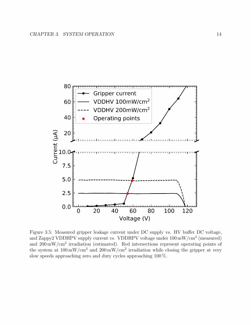
3.6 Toggling of HV buffers driving MEMS gripper at 200 mW/cm2 irradiation. SCµMGPIO pins 4 and 5 are enabling/disabling 59 V HV buffered outputs D1 and D2(respectively) on Zappy2. GPIOs toggling at 5.9 Hz with a 60 % duty cycle at a180 degree phase offset from each other. . . . . . . . . . . . . . . . . . . . . . . 15
iv
List of Tables
1.1 SARA Weight Specifications . . . . . . . . . . . . . . . . . . . . . . . . . . . . . 2
2.1 SCµM System Clocks . . . . . . . . . . . . . . . . . . . . . . . . . . . . . . . . . 42.2 SCµM Operating Current (1.5 V) . . . . . . . . . . . . . . . . . . . . . . . . . . 52.3 Solar Output Specifications at 100 mW/cm2 Irradiation . . . . . . . . . . . . . . 6
3.1 GPIOoutput Specifications . . . . . . . . . . . . . . . . . . . . . . . . . . . . . . . 13
v
Acknowledgments
I would like to acknowledge all of the people involved in the development of
• SCUM: Filip Maksimovic, Brad Wheeler, David C. Burnett, Osama Khan, Sahar Mesri,Ioana Suciu (Universitat Oberta de Catalunya), Lydia Lee, Arvind Sundararajan, BobZhou, Rachel Zoll, Andrew Ng, Tengfei Chang (Inria, EVA Team), Xavier Villajosana(Universitat Oberta de Catalunya), Thomas Watteyne (Inria, EVA Team), Ali Nikne-jad, and Kristofer S.J. Pister
• Zappy2: Jan Rentmeister (Dartmouth), Professor Jason Stauth (Dartmouth)
• The MEMS Gripper: Daniel Teal, Hani Gomez, Craig Schindler, Dillon Acker-Jamesand Wei Li
I would like to give a special thanks to the talented undergraduate researcher AustinPatel. It has been a privilege working with him. I have appreciated his kind personality,dedication and perseverance to getting what needs to be done done (e.g. 3 a.m. debugsessions, weekend work marathons, conference paper deadlines, etc).
I would like to thank my partner, Sanchala, for her support, conversations, laughter andwords of encouragement during the tough times.
I would like to thank my advisors Kris and Ali for believing in me and pushing me to bea better researcher.
Last but not least, I would like to thank my dad, my mom, brother and sister. I knowmoving across the country and seeing each other one or two times a year was a big change.They were always there with a bright smile when I went home. Thank you for listening tomy struggles and celebrating my victories. I dedicated this project to my mother Sara. Shehas been a leader in our family’s education. If it wasn’t for her relentless determination toget us the education she was never allowed to have I would not be where I am today.
This work was supported by the National Science Foundation Graduate Research Fellow-ship Program under Grant No. DGE 1752814. Any opinions, findings, and conclusions orrecommendations expressed in this material are those of the authors and do not necessarilyreflect the views of the National Science Foundation.
1
Chapter 1
Introduction
One ideal for an autonomous microrobotic system is one composed of motors, mechanisms,sensing, computation, communication, and power, which is able to interact with its envi-ronment and the internet in an intelligent manner. Much progress has been made in thedevelopment of all of the required components, and in the integration of full systems. Thisthesis reports a modest level of autonomy in a modular combination of a small number ofcomponents, with application to a broader set of microrobots. The motor and mechanismused here is a MEMS gripper described in [25]. The gripper is a single degree-of-freedomactuator, very simple from a robotics perspective. But it is made in a MEMS fabrication pro-cess which has been used to fabricate more complicated robot structures, such as jumpers [26]and a twelve degree-of-freedom hexapod [8], as well as a quadthruster ionocraft [10]. Thejumper and walker use the same basic electrostatic inchworm motor as the gripper. Thehigh voltage chip used here, Zappy2, was designed to drive this type of motor.
Previous work on untethered systems has shown that small robots are able to accomplishinteresting tasks in healthcare and bioengineering [27], and construction [12]. In many casesthese untethered robots might benefit from a wireless microgripper attachment, as wouldsome of the autonomous robots below.
There are many small autonomous robot systems in the multiple cubic inch size range[22, 21, 2]. Communication is a key enabler in several of these systems [22, 9]. Indeed,communication may be the only area in which man-made microrobots can outperform theirnatural counterparts. While IR communication is simple and useful for local operations, RFcommunication allows longer-range, multi-hop mesh networks, and easier integration intoexisting networks and infrastructure. The Bluetooth chip used by Iyer, et al. [13] allowedthem to send images over 120 meters. The radio used by Sabelhaus et al. [22] speaks the802.15.4 PHY and MAC protocol natively. This protocol is the basis of a highly reliable lowpower mesh networking communication stack, OpenWSN [31]. The Single Chip micro Mote,SCµM, was designed to perform the computation and communication required by swarmsof simple microrobots, and is able to run the OpenWSN stack [4]. It has some features incommon with the chip developed by Zhang et al. [35].
There have been several autonomous microrobots in the sub-gram size range, mostly
CHAPTER 1. INTRODUCTION 2
Figure 1.1: MEMS Gripper, HV Buffer & Solar Cell Array Chip, Single Chip Micro Mote(left to right). Two SCµM chips are stacked due to initial SCµM malfunctioning. Thedimensions of SARA are 9.5×31.55 mm2
Table 1.1: SARA Weight Specifications
Item Mass (mg)Empty Flex PCB 71.8SCµM (Stacked) 8.6
Zappy 2 17.3MEMS Gripper 137.9
0402 Capacitor (22 µF VDDIO) 3.80805 Capacitor (100 µF VBAT) 26.20805 Capacitor (100 nF VDDH) 17.2
Solder and wirebonds 3.1Total Mass 285.9
aerial vehicles. The 10 mg robot built by Hollar et al. [11] used inchworm motors and asolar cell array and was able to do autonomous pushups, with a small amount of lateralmotion, under roughly one sun of illumination. The controller was a simple CMOS finitestate machine, with no sensor feedback. The 300 mg robot built by Churaman et al. [5] wasable to jump 11 body lengths when triggered by an on-board light sensor. The logic washard-wired. James et al. [15] were the first to achieve takeoff, however briefly, of a 190 mgrobot under 200 suns of illumination. The 259 mg robot built by Jafferis et al. [14] achievedmany body lengths of autonomous flight under only a few suns of illumination. Both of theselast two flapping wing robots used open-loop control, but included a digital microcontroller,indicating that future sensor integration will be possible.
CHAPTER 1. INTRODUCTION 3
Figure 1.2: System block diagram including power domains, phases of operation, and allcomponents.
Previous work has demonstrated the operation of electrostatic inchworm motors usingmulti-junction solar cell arrays [23], coupled with an external silicon leg-sweeping mechanism.Bellew et al. [1] demonstrated the integration of solar cells, CMOS, and MEMS into a singleprocess, pointing to a future in which the size, weight, and frustration associated with multi-chip assembly is minimized.
The work described here is a step toward demonstrating standards-compatible mesh-networked swarms of centimeter-scale microrobots.
4
Chapter 2
System Description
The SARA robot consists of three chips and three capacitors. In addition, two OpenMote BCC2538 IoT devices were used for RF communication between SARA and a laptop, one forsending commands to SCµM and the other for receiving from SCµM [30]. Additionally, aTeensy 3.6 microcontroller with an infrared LED was used to optically program and calibratethe SCµM chip [32]. The block diagram of the system can be seen in Figure 1.2.
2.1 SCµM: Crystal-Free Radio and Microprocessor
SCµM is a 3×2×0.3 mm3 CMOS SoC featuring an ARM Cortex-M0 microprocessor, BLEtransmitter, and a standards-compatible crystal-free 802.15.4 transceiver [17]. The chipalso features an ADC, 16 0.8 V to 3.6 V GPIOs, and an optical receiver used for opticalprogramming and calibration. SCµM requires only one 1.2 V to 1.8 V power supply connectedto VBAT to operate [17], but the GPIOs may be driven from a separate supply, VDDIO.In order for SCµM to properly drive the high voltage buffers on Zappy2, the solar cell arrayprovides VBAT = 1.8 V and VDDIO = 3.5 V.
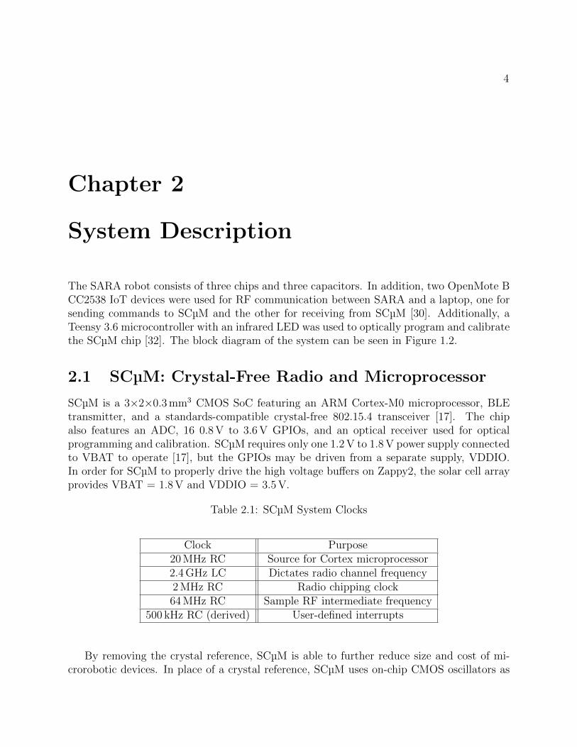
Table 2.1: SCµM System Clocks
Clock Purpose20 MHz RC Source for Cortex microprocessor2.4 GHz LC Dictates radio channel frequency2 MHz RC Radio chipping clock64 MHz RC Sample RF intermediate frequency
500 kHz RC (derived) User-defined interrupts
By removing the crystal reference, SCµM is able to further reduce size and cost of mi-crorobotic devices. In place of a crystal reference, SCµM uses on-chip CMOS oscillators as
CHAPTER 2. SYSTEM DESCRIPTION 5
Table 2.2: SCµM Operating Current (1.5 V)
State Approximate Current5 MHz Clock Rate (Normal) 350 µA
5 MHz Clock Rate (Radio on) 1.6 mA78 kHz Clock Rate (Low power) 200 µA
detailed in Table 2.1. However, this means that on-chip oscillators need to be calibrated toensure standards compatible 802.15.4 radio operation. Notably, the 2.4 GHz LC oscillatorused to set the local oscillator (LO) at the desired radio channel frequency is configured usingthree, 5-bit capacitive tuning DACs referred to as the coarse, mid, and fine tuning settings.Other calibrated clocks include the 20 MHz CPU clock, 2 MHz chipping clock, and 64 MHzreceiver intermediate frequency sampling clock. Calibration of these clocks has been suc-cessfully demonstrated using several different approaches, including an optical programmer[32], temperature-based calibration [34, 18], and RF-based calibration using only packetsoverheard [28, 29, 3]. The work reported here used the optical programmer.
During normal operation the 20 MHz RC oscillator is divided down to 5 MHz for useas the clock for the Cortex microprocessor. For lower power consumption this oscillator isdivided to 78 kHz. The current consumption at these various operating conditions can beseen in Table 2.2.
2.2 Zappy 2: Solar Cell and High Voltage Buffers
Zappy2 contains the photovoltaic (PV) arrays that power the robot and high voltage buffersto drive the motors. The 3.26×3.5 mm2 chip is fabricated in a 650 V trench-isolated CMOSprocess and contains more than two hundred PV cells [20]. These PV cells are grouped inseries to provide three voltage domains: one to power SCµM (VBATPV; 1.8 V), one as areference for the SCµM’s GPIOs (VDDIOPV; 3.5 V), and one as a high voltage rail to powerthe electrostatic motors on the MEMS gripper (VDDHPV; 119 V). The performance char-acteristics of the solar cell arrays are shown in Table 2.3. Three capacitors of size 100 µF,22 µF, and 100 nF are used to maintain voltage across VBAT, VDDIO, and VDDH, respec-tively (Figure 1.2). In the SARA robot, the lowest allowable successful operating voltagesof VBAT, VDDIO and VDDH were measured to be 1.3 V, 3.3 V and 40 V, respectively.
Zappy2 also contains four high voltage (HV) buffers, two of which are needed to drive asingle inchworm motor. These buffers hard switch their outputs between 0 V and VDDHPVat a rate determined by the switching of the input signals. SCµM uses two GPIOs to drivetwo buffers, and a third GPIO to generate the CLKHV=100 kHz source needed for the Zappy2internal digital state machine.
Hard switching the HV lines is sub-optimal for electrical to mechanical conversion effi-
CHAPTER 2. SYSTEM DESCRIPTION 6
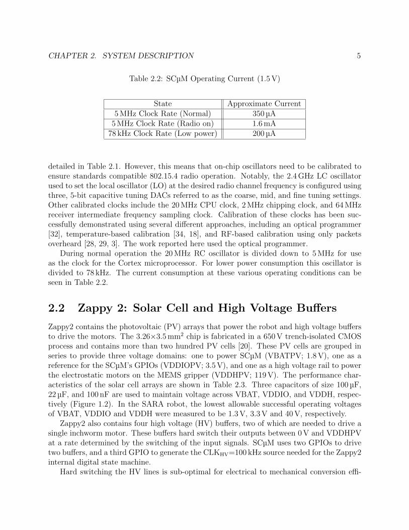
Table 2.3: Solar Output Specifications at 100 mW/cm2 Irradiation
VBATPV VDDIOPV VDDHPVVOC 1.8 V 3.5 V 119 VISC 280 µA 16 µA 2.4 µA
ciency, and because it requires significant capacitance on the HV supply to avoid droopingin the supply voltage. Both of these problems can be solved using an improved version ofthe HV chip [16], but for SARA we simply added a HV capacitor that was large comparedto the load capacitance of the electrostatic actuators, roughly 70 pF.
For this SARA integration, the solar array is provided with 200 mW/cm2 irradiation toprovide VBATPV to SCµM with 560 µA at 1.86 V.
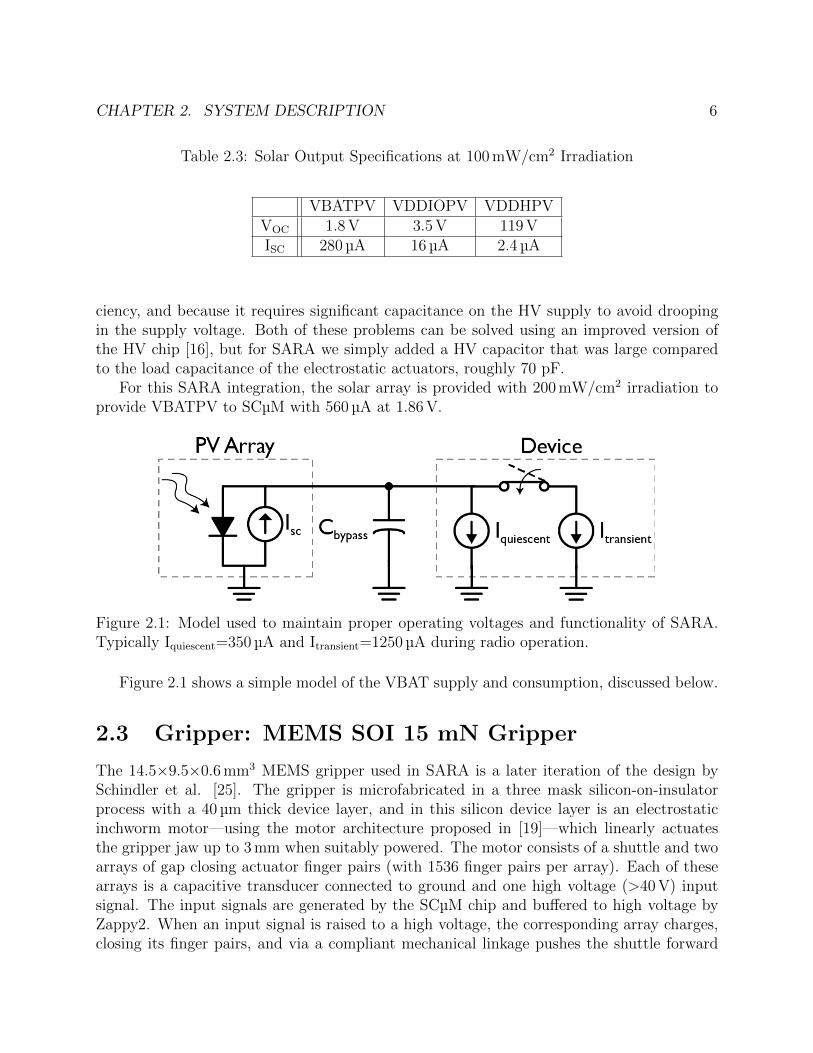
Figure 2.1: Model used to maintain proper operating voltages and functionality of SARA.Typically Iquiescent=350 µA and Itransient=1250 µA during radio operation.
Figure 2.1 shows a simple model of the VBAT supply and consumption, discussed below.
2.3 Gripper: MEMS SOI 15 mN Gripper
The 14.5×9.5×0.6 mm3 MEMS gripper used in SARA is a later iteration of the design bySchindler et al. [25]. The gripper is microfabricated in a three mask silicon-on-insulatorprocess with a 40 µm thick device layer, and in this silicon device layer is an electrostaticinchworm motor—using the motor architecture proposed in [19]—which linearly actuatesthe gripper jaw up to 3 mm when suitably powered. The motor consists of a shuttle and twoarrays of gap closing actuator finger pairs (with 1536 finger pairs per array). Each of thesearrays is a capacitive transducer connected to ground and one high voltage (>40 V) inputsignal. The input signals are generated by the SCµM chip and buffered to high voltage byZappy2. When an input signal is raised to a high voltage, the corresponding array charges,closing its finger pairs, and via a compliant mechanical linkage pushes the shuttle forward
CHAPTER 2. SYSTEM DESCRIPTION 7
2 µm then holds it in place. If the second array is then charged and the first is released, theshuttle moves an additional 2 µm. Driving the two arrays with >50 % duty cycle square waves180 degrees out of phase creates continuous movement. When both arrays are dischargedsimultaneously, the shuttle is free to move and is retracted by a silicon serpentine spring;this is how the gripper jaw returns to its original position.
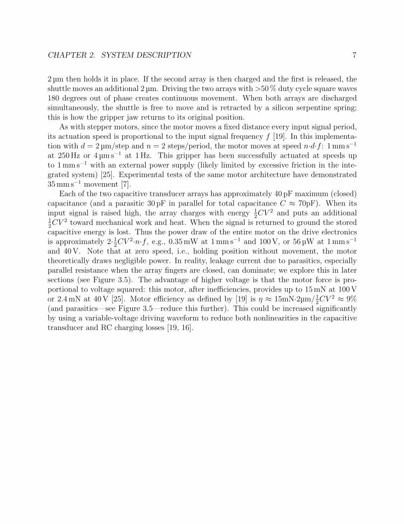
As with stepper motors, since the motor moves a fixed distance every input signal period,its actuation speed is proportional to the input signal frequency f [19]. In this implementa-tion with d = 2 µm/step and n = 2 steps/period, the motor moves at speed n·d·f : 1 mm s−1
at 250 Hz or 4 µm s−1 at 1 Hz. This gripper has been successfully actuated at speeds upto 1 mm s−1 with an external power supply (likely limited by excessive friction in the inte-grated system) [25]. Experimental tests of the same motor architecture have demonstrated35 mm s−1 movement [7].
Each of the two capacitive transducer arrays has approximately 40 pF maximum (closed)capacitance (and a parasitic 30 pF in parallel for total capacitance C ≈ 70pF). When itsinput signal is raised high, the array charges with energy 1
2CV 2 and puts an additional
12CV 2 toward mechanical work and heat. When the signal is returned to ground the stored
capacitive energy is lost. Thus the power draw of the entire motor on the drive electronicsis approximately 2·1
2CV 2·n·f , e.g., 0.35 mW at 1 mm s−1 and 100 V, or 56 µW at 1 mm s−1
and 40 V. Note that at zero speed, i.e., holding position without movement, the motortheoretically draws negligible power. In reality, leakage current due to parasitics, especiallyparallel resistance when the array fingers are closed, can dominate; we explore this in latersections (see Figure 3.5). The advantage of higher voltage is that the motor force is pro-portional to voltage squared: this motor, after inefficiencies, provides up to 15 mN at 100 Vor 2.4 mN at 40 V [25]. Motor efficiency as defined by [19] is η ≈ 15mN·2µm/1
2CV 2 ≈ 9%
(and parasitics—see Figure 3.5—reduce this further). This could be increased significantlyby using a variable-voltage driving waveform to reduce both nonlinearities in the capacitivetransducer and RC charging losses [19, 16].
8
Chapter 3
System Operation
The integrated SARA microsystem operates in 5 phases indicated in Figure 1.2 and detailedin this section.
3.1 Phase 1: Optical Calibration
A Teensy 3.6 microcontroller with an IR LED is used to send signals to the optical receiveron SCµM in order to bootload a program [32]. After programming, SCµM enters an opticalcalibration phase. This calibration is needed to calibrate the CMOS oscillators on SCµMsince the chip lacks a crystal reference. The same IR programmer sends 20 pulses of an opticalsignal at 10 Hz to trigger optical interrupts on SCµM [32]. Upon receiving an interrupt,SCµM uses the time between interrupts as an absolute reference for calibrating its oscillators.The calibrated clocks include a 20 MHz HF CPU clock, a 2 MHz RC chipping clock, and anIF radio clock.
During bootup, SCµM has the following VBAT current transient: 300 µA unprogrammed/idle,350 µA for 0.5 s while programming and initializing, 1.6 mA optical calibration for 2 s, andlastly idle at 350 µA. The 1.6 mA exceeds the 560 µA provided by the solar cells at 200 mW/cm2.Thus, while calibrating, SCµM is connected to an external 1.7 V VBAT. Additionally, anexternal 3.3 V VDDIO source is connected during calibration to ensure that the Zappy2 FSMis properly initialized.
3.2 Phase 2: Solar Power and LC Calibration
Once calibrated, the external 1.7 V and 3.3 V power sources are disconnected and SCµMoperates autonomously on solar power from Zappy2. Under 200 mW/cm2 irradiation (2 suns)provided by a fiber optic light illuminator, the solar cells provide 560 µA at 1.86 V. Thisprovides power to operate SCµM at a reduced 78 kHz clock rate (IVBAT=200 µA) betweenperiods of full speed operation at 5 MHz (IVBAT=350 µA). The 2 suns illumination was chosenas the 560 µA current provided exceeds the IVBAT=350 µA idle current. Additionally, it
CHAPTER 3. SYSTEM OPERATION 9
provides enough current along with the 100 µF VBAT capacitor to operate SCµM with radio-on IVBAT=1.6 mA for ~2 ms periods while still maintaining 802.15.4 standard compatibility.Further justification is provided in section 3.3.
Additional calibration is required to set the radio local oscillator frequency to properlytransmit 802.15.4 packets at 2.405 GHz for channel 11 as well as receive packets at 2.410 GHzon 802.15.4 channel 12. This additional calibration is needed as the optical programmingphase is not able to accurately calibrate the local oscillator. This occurs because whencalibrating the local oscillator the divider chain is required to be turned on which increasesthe current consumption from 1.6 mA to more than 2 mA. Attempts to turn the divider chainoff after calibration resulted in the local oscillator shifting it’s frequency. Thus, to calibrate,SCµM sweeps across tuning settings with the divider chain off for each of the three 5-bitcapacitive DACs used to set the frequency for the LC local oscillator (coarse, mid, and finesettings). The LC codes are swept until a packet is properly transmitted on channel 11 to anRX OpenMote. Next, the LC codes are again swept until SCµM properly receives a packeton channel 12 from an TX OpenMote (Figure 1.2). The TX and RX LC configuration codesare then fixed and SCµM is now properly calibrated to transmit and receive on those specificchannels.
The LC is calibrated with the goal of maintaining 802.15.4 standard compatibility. Thisstandard defines a ±40 ppm maximum local oscillator frequency error which is difficult toachieve without a crystal reference. This is especially challenging in an energy-constrainedand solar-powered system due to large voltage drops across the 100 µF VBAT capacitor thatoccur during radio operation which shift the frequencies of the CMOS oscillators (see section3.3).
Furthermore, this calibration is complicated by the 160 ppm/°C [33] and −40 ppm/°C [17]temperature dependence of the 2 MHz radio chipping clock and 2.4 GHz radio local oscillator,respectively.
In prior work, SCµM and Zappy2 have been integrated into a wireless temperature sensingnode featuring temperature based LC compensation across a temperature range of 35.5 °Cto 40.0 °C [18]. For this integration the LC codes are fixed as previously described ratherthan continuously calibrated. Future work could integrate this continuous LC calibrationinto the SARA robot.
3.3 Phase 3: Receive Packets
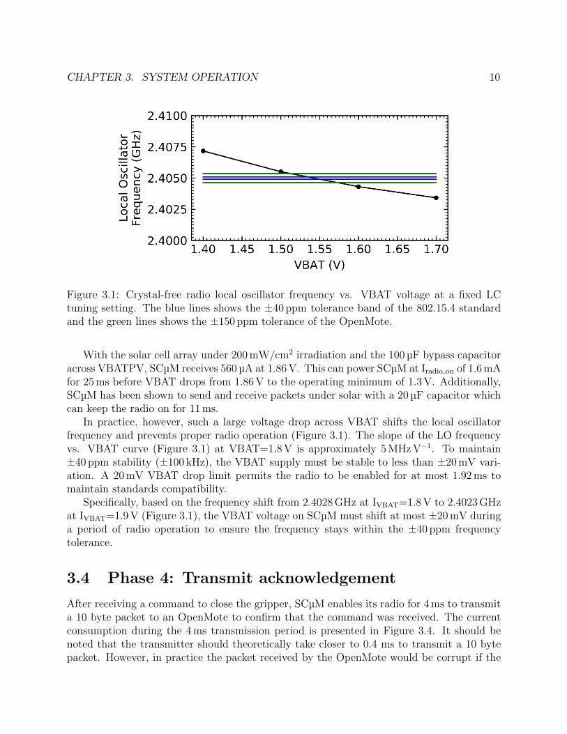
While operating, the radio is enabled for 1 ms to attempt to receive an 802.15.4 packetfrom a TX OpenMote (Figure 1.2). This requires 1.6 µC of charge for Iradio on=1.6 mA. Thetransient current of SCµM during radio operation under solar power can be seen in Figure3.2. The 1 ms radio on period was chosen to minimize voltage drop on VBAT while the radiois on. The TX OpenMote is continuously transmitting 6 byte packets with a command toactuate the gripper. Phase φ3 is repeated approximately every second until a command isreceived. The time in between repetitive Phase φ3s could be reduced.
CHAPTER 3. SYSTEM OPERATION 10
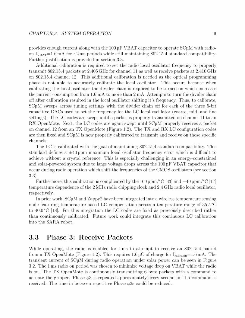
Figure 3.1: Crystal-free radio local oscillator frequency vs. VBAT voltage at a fixed LCtuning setting. The blue lines shows the ±40 ppm tolerance band of the 802.15.4 standardand the green lines shows the ±150 ppm tolerance of the OpenMote.
With the solar cell array under 200 mW/cm2 irradiation and the 100 µF bypass capacitoracross VBATPV, SCµM receives 560 µA at 1.86 V. This can power SCµM at Iradio on of 1.6 mAfor 25 ms before VBAT drops from 1.86 V to the operating minimum of 1.3 V. Additionally,SCµM has been shown to send and receive packets under solar with a 20 µF capacitor whichcan keep the radio on for 11 ms.
In practice, however, such a large voltage drop across VBAT shifts the local oscillatorfrequency and prevents proper radio operation (Figure 3.1). The slope of the LO frequencyvs. VBAT curve (Figure 3.1) at VBAT=1.8 V is approximately 5 MHz V−1. To maintain±40 ppm stability (±100 kHz), the VBAT supply must be stable to less than ±20 mV vari-ation. A 20 mV VBAT drop limit permits the radio to be enabled for at most 1.92 ms tomaintain standards compatibility.
Specifically, based on the frequency shift from 2.4028 GHz at IVBAT=1.8 V to 2.4023 GHzat IVBAT=1.9 V (Figure 3.1), the VBAT voltage on SCµM must shift at most ±20 mV duringa period of radio operation to ensure the frequency stays within the ±40 ppm frequencytolerance.
3.4 Phase 4: Transmit acknowledgement
After receiving a command to close the gripper, SCµM enables its radio for 4 ms to transmita 10 byte packet to an OpenMote to confirm that the command was received. The currentconsumption during the 4 ms transmission period is presented in Figure 3.4. It should benoted that the transmitter should theoretically take closer to 0.4 ms to transmit a 10 bytepacket. However, in practice the packet received by the OpenMote would be corrupt if the
CHAPTER 3. SYSTEM OPERATION 11
Figure 3.2: VBAT current during wireless 802.15.4 receive (200 mW/cm2 irradiation; 47 µFVBAT bypass capacitor). φ1: Low power (Fcortex=78 kHz), φ2: RX with radio on, φ3:periodic wake up to Fcortex=5 MHz
radio-on time was reduced too much. Transmitting packets is difficult due to high radio-oncurrent draw which causes a drop in VBAT voltage as charge is pulled from the 100 µFVBAT bypass capacitor. The challenges of maintaining the proper local oscillator frequencyare similar to those described in section 3.3, but now the radio is on for a longer periodof time (4 ms TX vs. 1 ms RX). Despite this increased radio on period, SCµM was able toproperly send packets as the transmission completes within the first 1 ms (corresponds to~40 mV VBAT drop; see Figure 3.3). Further development has decreased the total radio ontime to 1 ms. The OpenMote device used for these tests has a higher ±150 ppm frequencytolerance [33] over the ±40 ppm tolerance in the 802.15.4 standard. This increased tolerancewas leveraged to help receive packets from SCµM.
3.5 Phase 5: MEMS Gripper Actuation
After sending the acknowledgement that the command to close the gripper was received,SCµM begins sending three control signals through GPIO pins 1, 4, and 5 (powered byVDDIOPV) to Zappy2 (Figure 1.2). The GPIO output specifications can be seen in Table3.1. The first signal originates from the SCµM 500 kHz RF timer and is passed throughGPIO 1 (Figure 1.2) as the CLKHV clock source for the Zappy2 digital state machine. GPIOpins 4 and 5 are fed into two of the four high voltage (HV) buffers on Zappy2, which in turnconnect the gripper to the Zappy2 VDDHPV HV source. Toggling these pins from 0 V to3.5 V (with a 60 % duty cycle) and 180 degrees out of phase with each other actuates theelectrostatic inchworm motor of the gripper as described in section 2.3.
The current provided by the VDDHPV source on the solar cell and the current consump-
CHAPTER 3. SYSTEM OPERATION 12
Figure 3.3: VBAT voltage vs. time during wireless 802.15.4 transmit (200 mW/cm2 irradi-ation; 100 µF bypass capacitor). The dashed lines indicate the 4 ms period when the radiowas enabled.
Figure 3.4: VBAT current during wireless 802.15.4 transmit (200 mW/cm2 irradiation; 20 µFbypass capacitor). Phases: φ1: Fcortex=78 kHz low power mode and UART logging beforetransmit, φ2: Transmit 10 byte packet, φ3: Fcortex=5 MHz idle state
CHAPTER 3. SYSTEM OPERATION 13
Table 3.1: GPIOoutput Specifications
Specification ValueVDDIO 0.8-3.6 V
VDDAUX 0.8-1.2 VFmax @ HCLK = 10 MHz 734.25 KHz
IVDDIOleakage @ VDDIO = 3.3 V 4.37 nAIsink/source @ VDDIO = 3.3 V 19 mA
tion of the gripper while held at a DC voltage can be seen in Figure 3.5. The GPIO signalsand the corresponding buffered HV signals used for gripper actuation can be seen in Figure3.6.
We can use Figure 3.5 to determine the maximum speed operating points of the gripper.Because the gripper is capacitive, its speed, as in section 2.3, is determined solely by itsdriving frequency while it charges to the maximum voltage (and thus force) available. Atfast speeds, however, insufficient power is supplied to charge the gripper each signal periodso the voltage across its capacitance decreases. Once the voltage falls below the minimum40 V, the gripper fails to move. In this implementation, however, the gripper also has non-negligible leakage current draw under DC input. This sets the minimum power draw of thegripper at a given voltage as its speed approaches zero and duty cycle approaches 100%.
Thus, under 200 mW/cm2 irradiation, the operating point of the HV buffers and thegripper (for slow speeds and high duty cycles) is ~4.75 µA at ~59 V (Figure 3.5). Accordingto section 2.3, at this voltage, the force of the gripper is approximately 5.2 mN. If we assumethe leakage current graphed in Figure 3.5 only appears across the gripper when a motorarray is charged (i.e., the gap closing actuators are closed, which makes sense if their fingersare touching and causing a high-resistance short), then the proportion remaining poweravailable to actuate the gripper is 1 minus the duty cycle (here, 60%), for 4.75µA·59V·0.4 =0.11mW, which is sufficient for up to 920 µm s−1 speed. While testing the integrated SARAsystem at 200 mW/cm2 irradiation, GPIO toggling speeds up to 160 Hz resulted in movement,corresponding to a maximum speed of 640 µm s−1 closing the full 3 mm distance under solarpower in ~4.7 s (the slower-than-theoretical maximum achievable speed implies some of thegripper leakage is always present, reducing power available for movement, and friction mayalso play a role).
Each of the three Zappy2 voltage domains (VBATPV, VDDIOPV, and VDDHPV) mustmaintain a minimum voltage during actuation of the MEMS gripper. During gripper actu-ation, SCµM operates at a Fcortex=78 kHz with IVBAT=200 µA. This is within the 560 µAprovided by the VBATPV supply. The IVDDIO=1 µA consumed while toggling the GPIOpins at 160 Hz is well under the ~32 µA provided by the VDDIOPV source. Lastly, the VD-DHPV current while toggling and actuating the gripper is on average ~4.75 µA, smoothedby a 100 nF capacitor.
CHAPTER 3. SYSTEM OPERATION 14
Figure 3.5: Measured gripper leakage current under DC supply vs. HV buffer DC voltage,and Zappy2 VDDHPV supply current vs. VDDHPV voltage under 100 mW/cm2 (measured)and 200 mW/cm2 irradiation (estimated). Red intersections represent operating points ofthe system at 100 mW/cm2 and 200 mW/cm2 irradiation while closing the gripper at veryslow speeds approaching zero and duty cycles approaching 100 %.
CHAPTER 3. SYSTEM OPERATION 15
Figure 3.6: Toggling of HV buffers driving MEMS gripper at 200 mW/cm2 irradiation. SCµMGPIO pins 4 and 5 are enabling/disabling 59 V HV buffered outputs D1 and D2 (respectively)on Zappy2. GPIOs toggling at 5.9 Hz with a 60 % duty cycle at a 180 degree phase offsetfrom each other.
Finally, SCµM returns to Phase φ3 and begins listening for packets with ”actuate gripper”commands. The gripper has been demonstrated to repeatedly open and close after multipleiterations of the receive-acknowledge-actuate loop.
16
Chapter 4
Conclusion
Under conditions of steady 200 mW/cm2 irradiation on Zappy2 we have demonstrated fullSARA system operation. This includes receiving a six byte wireless command to actuatethe gripper from a standard 2.4 GHz 802.15.4 transmitter, transmitting a ten byte standards-compatible 802.15.4 packet as an acknowledgement, and autonomous microprocessor-controlledMEMS gripper actuation. The gripper has then been demonstrated to fully close at a rateof 640 µm s−1 to close the full 3 mm distance in roughly 4.7 s. After the gripper has closedthe SARA system successfully repeated the entire receive-acknowledge-actuate procedurerepeatedly without failure.
The integrated SARA microsystem with power, control, and mechanical elements pro-vides capabilities that previously would not be possible. An autonomous MEMS grippercould be used in micro assembly and manufacturing systems that require manipulation ata µm scale. Feedback control could be obtained by using the contact sensor on the MEMSgripper which could enable a µm scale caliper device to make size measurements of objects.Further developments will allow the integration of new jumping [24], walking [6], and fibercrawling [36] MEMS devices. For example, a MEMS inchworm motor could pull the SARAmicrosystem along a cord strung across an interior space to use SCµM as an autonomous,battery-free sensor. Multiple devices with SCµM and MEMS chips integrated could also beused in mesh networking systems for micro-scale robotic exploration.
17
Bibliography
[1] Colby L Bellew, Seth Hollar, and KSJ Pister. “An SOI process for fabrication of so-lar cells, transistors and electrostatic actuators”. In: TRANSDUCERS’03. 12th Inter-national Conference on Solid-State Sensors, Actuators and Microsystems. Digest ofTechnical Papers (Cat. No. 03TH8664). Vol. 2. IEEE. 2003, pp. 1075–1078.
[2] Gilles Caprari and Roland Siegwart. “Mobile micro-robots ready to use: Alice”. In: 2005IEEE/RSJ international conference on intelligent robots and systems. IEEE. 2005,pp. 3295–3300.
[3] T. Chang et al. “QuickCal: Assisted Calibration for Crystal-Free Micromotes”. In:IEEE Internet of Things Journal 8.3 (2021), pp. 1846–1858. doi: 10.1109/JIOT.2020.3015725.
[4] Tengfei Chang et al. “6TiSCH on SCµM:Running a Synchronized Protocol Stack with-out Crystals”. In: ACM Embedded Wireless Systems and Networks. 2020.
[5] Wayne Churaman et al. “The First Launch of an Autonomous Thrust-Driven Mi-crorobot Using Nanoporous Energetic Silicon”. In: Microelectromechanical Systems,Journal of 21 (Feb. 2012), pp. 198–205. doi: 10.1109/JMEMS.2011.2174414.
[6] D. S. Contreras, D. S. Drew, and K. S. J. Pister. “First steps of a millimeter-scalewalking silicon robot”. In: 2017 19th International Conference on Solid-State Sensors,Actuators and Microsystems (TRANSDUCERS). 2017, pp. 910–913. doi: 10.1109/TRANSDUCERS.2017.7994197.
[7] D. S. Contreras and K. S. J. Pister. “Dynamics of electrostatic inchworm motors forsilicon microrobots”. In: 2017 International Conference on Manipulation, Automationand Robotics at Small Scales (MARSS). July 2017, pp. 1–6. doi: 10.1109/MARSS.2017.8001936.
[8] Daniel S. Contreras and K.S.J. Pister. “A Six-Legged MEMS Silicon Robot UsingMultichip Assembly”. In: Solid State Sensors and Actuators Workshop, Hilton Head.2018.
[9] Nikolaus Correll, Samuel Rutishauser, and Alcherio Martinoli. “Comparing coordi-nation schemes for miniature robotic swarms: A case study in boundary coverage ofregular structures”. In: Experimental Robotics. Springer. 2008, pp. 471–480.
BIBLIOGRAPHY 18
[10] Daniel S Drew et al. “Toward controlled flight of the ionocraft: a flying microrobotusing electrohydrodynamic thrust with onboard sensing and no moving parts”. In:IEEE Robotics and Automation Letters 3.4 (2018), pp. 2807–2813.
[11] S. Hollar et al. “Solar powered 10 mg silicon robot”. In: The Sixteenth Annual In-ternational Conference on Micro Electro Mechanical Systems, 2003. MEMS-03 Kyoto.IEEE. 2003, pp. 706–711. doi: 10.1109/MEMSYS.2003.1189847.
[12] Allen Hsu et al. “Application of micro-robots for building carbon fiber trusses”. In:2016 international conference on manipulation, automation and robotics at small scales(MARSS). IEEE. 2016, pp. 1–6.
[13] Vikram Iyer et al. “Wireless steerable vision for live insects and insect-scale robots”.In: Science robotics 5.44 (2020).
[14] Noah Jafferis et al. “Untethered flight of an insect-sized flapping-wing microscale aerialvehicle”. In: Nature 570 (June 2019), pp. 491–495. doi: 10.1038/s41586-019-1322-0.
[15] J. James et al. “Liftoff of a 190 mg Laser-Powered Aerial Vehicle: The Lightest WirelessRobot to Fly”. In: 2018 IEEE International Conference on Robotics and Automation(ICRA). 2018, pp. 3587–3594. doi: 10.1109/ICRA.2018.8460582.
[16] Yanqiao Li, Benjamin L Dobbins, and Jason T Stauth. “An Optically Powered, High-Voltage, Switched-Capacitor Drive Circuit for Microrobotics”. In: IEEE Journal ofSolid-State Circuits (2020).
[17] Filip Maksimovic et al. “A Crystal-Free Single-Chip Micro Mote with Integrated802.15.4 Compatible Transceiver, sub-mW BLE Compatible Beacon Transmitter, andCortex M0”. In: VLSI 2019. IEEE. 2019.
[18] Alex Moreno et al. “Solar-Powered Crystal-Free 802.15.4 Wireless Temperature Sen-sor”. In: 2020 IEEE Sensors. IEEE. 2020, pp. 1–4.
[19] I. Penskiy and S. Bergbreiter. “Optimized electrostatic inchworm motors using a flex-ible driving arm”. en. In: Journal of Micromechanics and Microengineering 23.1 (Dec.2012). Publisher: IOP Publishing, p. 015018. issn: 0960-1317. doi: 10.1088/0960-1317/23/1/015018. (Visited on 10/12/2020).
[20] Jan S. Rentmeister et al. “A 120-330V, sub-µA, 4-Channel Driver for MicroroboticActuators with Wireless- Optical Power Delivery and over 99% Current Efficiency”.In: 2020 IEEE Symposium on VLSI Circuits. Honolulu, HI, USA, 2020.
[21] Michael Rubenstein et al. “Kilobot: A low cost robot with scalable operations designedfor collective behaviors”. In: Robotics and Autonomous Systems 62.7 (2014), pp. 966–975.
[22] Andrew P Sabelhaus et al. “TinyTeRP: A tiny terrestrial robotic platform with mod-ular sensing”. In: 2013 IEEE International Conference on Robotics and Automation.IEEE. 2013, pp. 2600–2605.
BIBLIOGRAPHY 19
[23] Ken Saito et al. “Study on electrostatic inchworm motor device for a heterogeneousintegrated microrobot system”. In: Transactions of The Japan Institute of ElectronicsPackaging 12 (2019), E18–009.
[24] C. B. Schindler et al. “A Jumping Silicon Microrobot with Electrostatic Inchworm Mo-tors and Energy Storing Substrate Springs”. In: 2019 20th International Conferenceon Solid-State Sensors, Actuators and Microsystems Eurosensors XXXIII (TRANS-DUCERS EUROSENSORS XXXIII). 2019, pp. 88–91. doi: 10.1109/TRANSDUCERS.2019.8808463.
[25] Craig Schindler et al. “15 Millinewton Force, 1 Millimeter Displacement, Low-PowerMEMS Gripper”. In: IEEE MEMS. 2020.
[26] Craig B Schindler et al. “A jumping silicon microrobot with electrostatic inchwormmotors and energy storing substrate springs”. In: 2019 20th International Conferenceon Solid-State Sensors, Actuators and Microsystems & Eurosensors XXXIII (TRANS-DUCERS & EUROSENSORS XXXIII). IEEE. 2019, pp. 88–91.
[27] Metin Sitti et al. “Biomedical applications of untethered mobile milli/microrobots”.In: Proceedings of the IEEE 103.2 (2015), pp. 205–224.
[28] Ioana Suciu et al. “Dynamic Channel Calibration on a Crystal-Free Mote-on-a-Chip”.In: IEEE Access 7 (2019), pp. 120884–120900.
[29] Ioana Suciu et al. “Experimental clock calibration on a crystal-free mote-on-a-chip”. In:IEEE INFOCOM 2019-IEEE Conference on Computer Communications Workshops(INFOCOM WKSHPS). IEEE. 2019, pp. 608–613.
[30] Xavier Vilajosana et al. “OpenMote: Open-Source Prototyping Platform for the Indus-trial IoT”. In: International Conference on Ad Hoc Networks (AdHocNets). San Remo,Italy, Sept. 2015, pp. 211–222. doi: 10.1007/978-3-319-25067-0\_17.
[31] Thomas Watteyne et al. “OpenWSN: a standards-based low-power wireless develop-ment environment”. In: Transactions on Emerging Telecommunications Technologies23.5 (2012), pp. 480–493.
[32] Brad Wheeler et al. “A Low-Power Optical Receiver for Contact-free Programmingand 3D Localization of Autonomous Microsystems”. In: IEEE UEMCON. 2019.
[33] Bradley Wheeler. “Low Power, Crystal-Free Design for Monolithic Receivers”. PhDthesis. EECS Department, University of California, Berkeley, May 2019.
[34] T. Yuan et al. “Temperature Calibration on a Crystal-Free Mote”. In: 2020 IEEE 6thWorld Forum on Internet of Things (WF-IoT). 2020, pp. 1–5. doi: 10.1109/WF-
IoT48130.2020.9221351.
[35] Xuan Zhang et al. “A fully integrated battery-powered system-on-chip in 40-nm CMOSfor closed-loop control of insect-scale pico-aerial vehicle”. In: IEEE Journal of Solid-State Circuits 52.9 (2017), pp. 2374–2387.
BIBLIOGRAPHY 20
[36] R. S. Zoll et al. “MEMS-Actuated Carbon Fiber Microelectrode for Neural Recording”.In: IEEE Transactions on NanoBioscience 18.2 (2019), pp. 234–239. doi: 10.1109/TNB.2019.2905505.
![[SelfOrg]2-1.1 Self-Organization in Autonomous Sensor/Actuator Networks [SelfOrg] Dr.-Ing. Falko Dressler Computer Networks and Communication Systems Department](https://img.pdfslide.net/doc/110x75/56649dd95503460f94acf1a2/selforg2-11-self-organization-in-autonomous-sensoractuator-networks-selforg.jpg)
![[SelfOrg]2-4.1 Self-Organization in Autonomous Sensor/Actuator Networks [SelfOrg] Dr.-Ing. Falko Dressler Computer Networks and Communication Systems Department](https://img.pdfslide.net/doc/110x75/56649cdd5503460f949a800b/selforg2-41-self-organization-in-autonomous-sensoractuator-networks-selforg.jpg)


![[SelfOrg]2-5.1 Self-Organization in Autonomous Sensor/Actuator Networks [SelfOrg] Dr.-Ing. Falko Dressler Computer Networks and Communication Systems Department](https://img.pdfslide.net/doc/110x75/56649cb75503460f9497da29/selforg2-51-self-organization-in-autonomous-sensoractuator-networks-selforg.jpg)

![[SelfOrg]3-3.1 Self-Organization in Autonomous Sensor/Actuator Networks [SelfOrg] Dr.-Ing. Falko Dressler Computer Networks and Communication Systems Department](https://img.pdfslide.net/doc/110x75/56649e6f5503460f94b6cce1/selforg3-31-self-organization-in-autonomous-sensoractuator-networks-selforg.jpg)


![[SelfOrg]3-2.1 Self-Organization in Autonomous Sensor/Actuator Networks [SelfOrg] Dr.-Ing. Falko Dressler Computer Networks and Communication Systems Department](https://img.pdfslide.net/doc/110x75/56649f565503460f94c7b14b/selforg3-21-self-organization-in-autonomous-sensoractuator-networks-selforg.jpg)


![[SelfOrg]4.1 Self-Organization in Autonomous Sensor/Actuator Networks [SelfOrg] Dr.-Ing. Falko Dressler Computer Networks and Communication Systems Department](https://img.pdfslide.net/doc/110x75/56649ef05503460f94c014fe/selforg41-self-organization-in-autonomous-sensoractuator-networks-selforg.jpg)

![Self-Organization in Autonomous Sensor/Actuator …dressler/teaching/selbstorganisation-ss05/02-7... · Self-Organization in Autonomous Sensor/Actuator Networks [SelfOrg] ... Radio](https://img.pdfslide.net/doc/110x75/5aea05417f8b9a6d4f918554/self-organization-in-autonomous-sensoractuator-dresslerteachingselbstorganisation-ss0502-7self-organization.jpg)
![[SelfOrg]5.1 Self-Organization in Autonomous Sensor/Actuator Networks [SelfOrg] Dr.-Ing. Falko Dressler Computer Networks and Communication Systems Department](https://img.pdfslide.net/doc/110x75/56649e025503460f94aec8ed/selforg51-self-organization-in-autonomous-sensoractuator-networks-selforg.jpg)


![Self-Organization in Autonomous Sensor/Actuator Networks [ SelfOrg ]](https://img.pdfslide.net/doc/110x75/568164ac550346895dd6ae05/self-organization-in-autonomous-sensoractuator-networks-selforg--56ccb95a192a3.jpg)