Embed Size (px)
Citation preview
Small-Satellite Magnetorquer Attitude Control System Modelling and Simulation
Xiaoguang Yi a and Amir Anvar a
a School of Mechanical Engineering, Faculty of Engineering, Computer, and Mathematical Science,
The University of Adelaide, Adelaide, South Australia, AUSTRALIA 5005
Emails: [email protected] ; [email protected]
Abstract: The field of Ocean Robotics Engineering is expanding rapidly and there is demand for low cost, compact and light-weight small-satellites to communicate with remote ocean bound devices. This paper discusses the work carried out with the school’s microsatellite group and focusses on the attitude control system which is vital for accurate satellite operation. Establishing a mathematical model for micro-satellite attitude control system contains positioning sensors system, kinematic and dynamic concept of the attitude and statistic processing methods and so on. In this dissertation, based on the Euler angle and Quaternion principles, we built the attitude kinematic model. By considering the magnetometers data and Fuzzy Control method the attitude estimation, was studied and investigated. The paper would also provide a brief investigation towards the modes of attitude control process and analysis. The result of unloading of a momentum wheel by magnetic rotation and precession damping is studied using Simulink. The control system model is included with relationship of three-axis motion simulation, to determine the pitch-channel and roll-yaw channel respectively. This process would define the stability controller problem of wheel unloading and protected mode for small-satellite stabilization.
Keywords: Microsatellite, Small Satellite, Momentum wheel, Attitude determination, Attitude Control, Simulation, Modeling, Attitude stabilizationIntroduction, Fuzzy Logic, Euler angle, Quaternion
20th International Congress on Modelling and Simulation, Adelaide, Australia, 1–6 December 2013 www.mssanz.org.au/modsim2013
984
Xiaoguang Yi, Amir Anvar; Small-Satellite Magnetorquer Attitude Control System Modelling and Simulation 1. INTRODUCTION
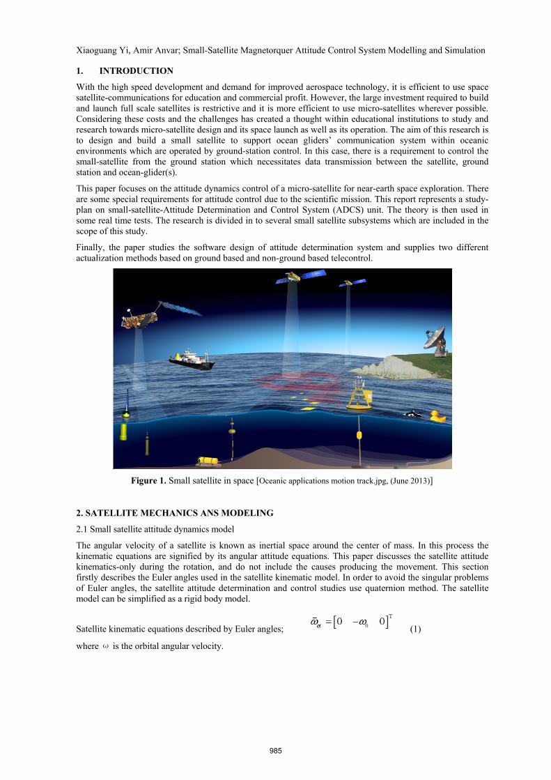
With the high speed development and demand for improved aerospace technology, it is efficient to use space satellite-communications for education and commercial profit. However, the large investment required to build and launch full scale satellites is restrictive and it is more efficient to use micro-satellites wherever possible. Considering these costs and the challenges has created a thought within educational institutions to study and research towards micro-satellite design and its space launch as well as its operation. The aim of this research is to design and build a small satellite to support ocean gliders’ communication system within oceanic environments which are operated by ground-station control. In this case, there is a requirement to control the small-satellite from the ground station which necessitates data transmission between the satellite, ground station and ocean-glider(s).
This paper focuses on the attitude dynamics control of a micro-satellite for near-earth space exploration. There are some special requirements for attitude control due to the scientific mission. This report represents a study-plan on small-satellite-Attitude Determination and Control System (ADCS) unit. The theory is then used in some real time tests. The research is divided in to several small satellite subsystems which are included in the scope of this study.
Finally, the paper studies the software design of attitude determination system and supplies two different actualization methods based on ground based and non-ground based telecontrol.
Figure 1. Small satellite in space [Oceanic applications motion track.jpg, (June 2013)]
2. SATELLITE MECHANICS ANS MODELING
2.1 Small satellite attitude dynamics model
The angular velocity of a satellite is known as inertial space around the center of mass. In this process the kinematic equations are signified by its angular attitude equations. This paper discusses the satellite attitude kinematics-only during the rotation, and do not include the causes producing the movement. This section firstly describes the Euler angles used in the satellite kinematic model. In order to avoid the singular problems of Euler angles, the satellite attitude determination and control studies use quaternion method. The satellite model can be simplified as a rigid body model.
Satellite kinematic equations described by Euler angles; (1)
where ω is the orbital angular velocity.
985
Xiaoguang Yi, Amir Anvar; Small-Satellite Magnetorquer Attitude Control System Modelling and Simulation The satellite attitude dynamics equation is as follow:
(2)
(3)
The , represents the small rotation angles. (4)
2.2 Satellite Quaternion Kinematic Equations
Motion of the satellite can be abstracted simply as a rigid body motion by the translational and rotational components. Assume orbital coordinate system in spatial reference coordinate system, expressed as o, rotation coordinate system for the satellite body coordinate system is expressed as b, and b system at some moment relative to o system by quaternion vector is expressed as q and I is inertial reference coordinate system, with quaternion satellite kinematic equations is:
(5)
Can be written as: (6)
From the above we can know that, the use of quaternion for attitude control has no singularity, the equation is linear, computing friendly including no trigonometric functions.
Therefore, here we normally use mainly quaternion method to describe in satellite attitude
3. ZERO MOMENTUM WHEEL SATELLITE ATTITUDE CONTROL SYSTEM
3.1 Typical Zero Momentum Wheel Mounting Structure
Installation of the flywheel structure must consider factors such as reliability and power consumption, but we also need to consider the flywheel control precision and interference performance. From the viewpoint of the overall optimization of the flywheel mounting structure, one should try using a simple configuration, avoiding system failures caused by overly complex systems. Therefore for the reliability of the flywheel, the best way to consider the mounting structure for the zero momentum wheel attitude control system is as follows:
(1) Three orthogonal reaction wheels mounted along astral spindle, which is the simplest form of reaction wheels, no redundancy.
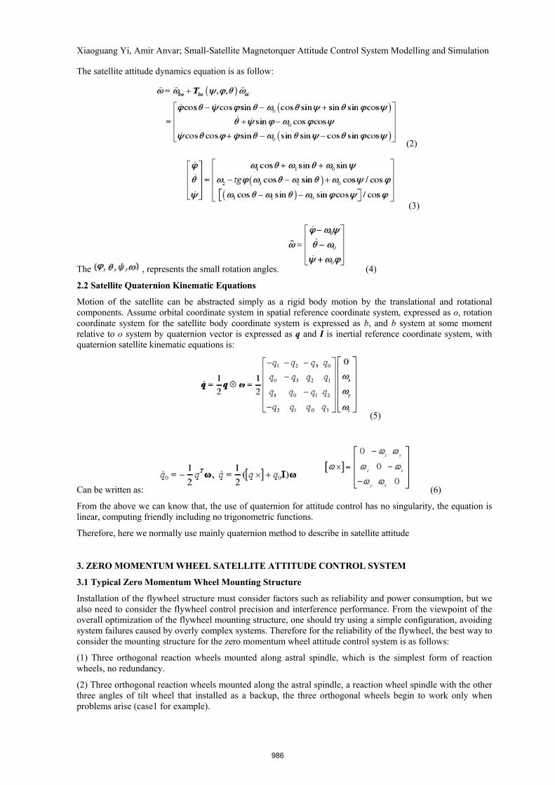
(2) Three orthogonal reaction wheels mounted along the astral spindle, a reaction wheel spindle with the other three angles of tilt wheel that installed as a backup, the three orthogonal wheels begin to work only when problems arise (case1 for example).
986
Xiaoguang Yi, Amir Anvar; Small-Satellite Magnetorquer Attitude Control System Modelling and Simulation
Figure 2. Typical structure of zero-momentum reaction wheel [10]
(3) The pitch axis plus ramp loading wheel configuration, the pitch shaft is mounted to a flywheel, XZ plane to install a flywheel, and the remaining two are ramp loading.
(4) Four reaction wheels installation are about the pitch axis symmetrical, evenly inclined on the axis of the flywheel.
(5) Four reaction wheels are installed about the pitch axis symmetrical, evenly inclined, projected on the flywheel coordinate plane.
3.2 The Design of Proportional-integral-derivative (PID) Controller
Following the analysis, the system can be simplified into a model diagram shown in Figure 3. In Figure3 , u is the controller output voltage motor control; T is the flywheel torque control of the motor output; H is the momentum of the flywheel torque; ω is the angular velocity of the star; a is the angle information of stars.
Figure 3. Simplex model of satellite based on zero-momentum reaction wheel actuator
The controller has two inputs: the satellite quaternion which is relative to the coordinate system fixed posture and the angular velocity relative to the coordinate system; output is the control voltage. The output voltage signal mainly controls motor rotation to drive the reaction flywheel and generate reaction torque on the satellite itself for controlling the attitude angle and angular velocity of the satellite.
The transfer function of the PID controller represented as follows:
(7)
In this case PID controller adding the open-loop transfer function is:
(8)
Substituting s = jω, the above equation can be written as:
(9)
When the ω= ωc the above equation is:
(10)
987
Xiaoguang Yi, Amir Anvar; Small-Satellite Magnetorquer Attitude Control System Modelling and Simulation
(11)
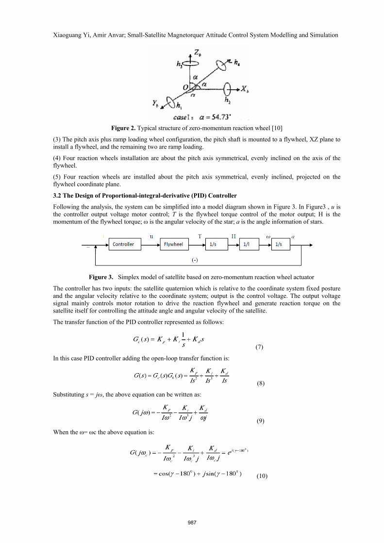
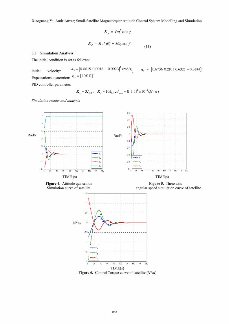
3.3 Simulation Analysis
The initial condition is set as follows:
initial velocity: ,
Expectations quaternion:
PID controller parameter:
.
Simulation results and analysis
TIME (s) TIME(s)
Figure 4. Attitude quaternion Figure 5. Three axis Simulation curve of satellite angular speed simulation curve of satellite
TIME(s)
Figure 6. Control Torque curve of satellite (N*m)
Rad/s
N*m
Rad/s
988
Xiaoguang Yi, Amir Anvar; Small-Satellite Magnetorquer Attitude Control System Modelling and Simulation 3.4 Fuzzy Logic Controller Design and Simulation
Fuzzy Logic control is a nonlinear control method based on artificial intelligence. Fuzzy logic controller design does not rely on the mathematical model of the controlled object. The controlled object model parameters have a strong capability for adaptation, even the same controller can be used for different spacecraft control purposes. This section describes the satellite attitude control which is a typical pure Fuzzy Logic controller design type called Mamdani, and attitude maneuver control. It also demonstrates the simulation and analysis of control system.
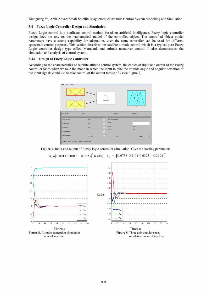
3.4.1 Design of Fuzzy Logic Controller
According to the characteristics of satellite attitude control system, the choice of input and output of the Fuzzy controller fades when we take the mode in which the input to take the attitude angle and angular-deviation of the input signals e and ce, to take control of the output torque of u (see Figure 7).
Figure 7. Input and output of Fuzzy logic controller Simulation. Give the starting parameters:
Time(s) Time(s)
Figure 8. Attitude quaternion simulation Figure 9. Three axis angular speed curve of satellite simulation curve of satellite
Rad/s
989
Xiaoguang Yi, Amir Anvar; Small-Satellite Magnetorquer Attitude Control System Modelling and Simulation
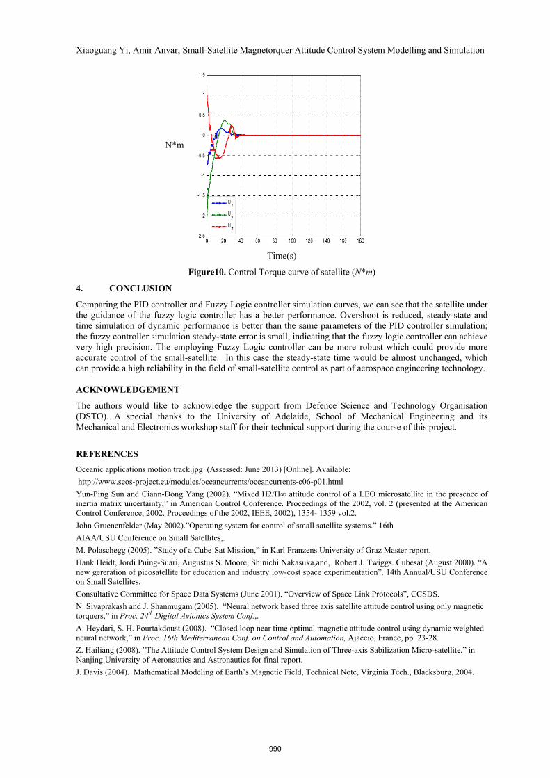
Time(s)
Figure10. Control Torque curve of satellite (N*m)
4. CONCLUSION
Comparing the PID controller and Fuzzy Logic controller simulation curves, we can see that the satellite under the guidance of the fuzzy logic controller has a better performance. Overshoot is reduced, steady-state and time simulation of dynamic performance is better than the same parameters of the PID controller simulation; the fuzzy controller simulation steady-state error is small, indicating that the fuzzy logic controller can achieve very high precision. The employing Fuzzy Logic controller can be more robust which could provide more accurate control of the small-satellite. In this case the steady-state time would be almost unchanged, which can provide a high reliability in the field of small-satellite control as part of aerospace engineering technology. ACKNOWLEDGEMENT
The authors would like to acknowledge the support from Defence Science and Technology Organisation (DSTO). A special thanks to the University of Adelaide, School of Mechanical Engineering and its Mechanical and Electronics workshop staff for their technical support during the course of this project.
REFERENCES
Oceanic applications motion track.jpg (Assessed: June 2013) [Online]. Available:
http://www.seos-project.eu/modules/oceancurrents/oceancurrents-c06-p01.html
Yun-Ping Sun and Ciann-Dong Yang (2002). “Mixed H2/H∞ attitude control of a LEO microsatellite in the presence of inertia matrix uncertainty,” in American Control Conference. Proceedings of the 2002, vol. 2 (presented at the American Control Conference, 2002. Proceedings of the 2002, IEEE, 2002), 1354- 1359 vol.2.
John Gruenenfelder (May 2002).”Operating system for control of small satellite systems.” 16th
AIAA/USU Conference on Small Satellites,.
M. Polaschegg (2005). ”Study of a Cube-Sat Mission,” in Karl Franzens University of Graz Master report.
Hank Heidt, Jordi Puing-Suari, Augustus S. Moore, Shinichi Nakasuka,and, Robert J. Twiggs. Cubesat (August 2000). “A new gereration of picosatellite for education and industry low-cost space experimentation”. 14th Annual/USU Conference on Small Satellites.
Consultative Committee for Space Data Systems (June 2001). “Overview of Space Link Protocols”, CCSDS.
N. Sivaprakash and J. Shanmugam (2005). “Neural network based three axis satellite attitude control using only magnetic torquers,” in Proc. 24th Digital Avionics System Conf.,.
A. Heydari, S. H. Pourtakdoust (2008). “Closed loop near time optimal magnetic attitude control using dynamic weighted neural network,” in Proc. 16th Mediterranean Conf. on Control and Automation, Ajaccio, France, pp. 23-28.
Z. Hailiang (2008). ”The Attitude Control System Design and Simulation of Three-axis Sabilization Micro-satellite,” in Nanjing University of Aeronautics and Astronautics for final report.
J. Davis (2004). Mathematical Modeling of Earth’s Magnetic Field, Technical Note, Virginia Tech., Blacksburg, 2004.
N*m
990


![Satellite Attitude Control Using Three Reaction Wheels · Satellite attitude control using three reaction wheels ... [12]. A reaction wheel is a device that applies torque ... The](https://img.pdfslide.net/doc/110x75/5b885d727f8b9abf5c8b699b/satellite-attitude-control-using-three-reaction-satellite-attitude-control-using.jpg)