Embed Size (px)
Citation preview

Smart Antenna Design and Implementation: A Simple Switched-Beam Antenna Array Based on a 8x8 Butler-Matrix Network
G.A. ADAMIDIS and I.O. VARDIAMBASIS
Microwave Communications & Electromagnetic Applications Laboratory, Telecommunications Division, Department of Electronics,
Technological Educational Institute (T.E.I.) of Crete - Chania Branch, Romanou 3, Chalepa, 73133 Chania, Crete,
GREECE
Abstract: - A simple switched-beam array system, capable to produce eight orthogonal uniform beams and some low side-lobe beams, is presented in this paper. The system consists of an eight-element linear phased array and a 8x8 Butler-matrix beam-forming network. System’s design and optimization was based on experimental results and computer simulations. A new compact layout topology for the 8x8 Butler-Matrix beam-forming network is presented in this work. The 8x8 Butler-Matrix network has been constructed on a single board surface of an extremely low cost dielectric material, the well-known FR4. Finally, radiation pattern measurements are presented in detail, in order to prove the excellent system’s performance. Keywords: - Smart antennas, Switched-beam antenna arrays, Space Division Multiple Access, SDMA, Butler-matrix network, Beam-forming. 1 Introduction 1.1 Switched-beam antennas in wireless communications industry The wireless communications industry is forced to improve the capacity of its systems. This is due to the exponentially escalating number of wireless services’ users. The problem can be solved by extending bandwidth on the current base stations or by adding new base-stations to the current infrastructure. This classical approach suffers from several problems like increased complexity and additional operational expenses. An alternative solution to the problem is the use of Space Division Multiple Access (SDMA) in each base station. The SDMA technique allows discrimination of the users standing at different angular positions around the base station and makes possible the reuse of the
existing bandwidth towards them. As a result, system’s capacity is expanded. SDMA can be easily implemented by the use of “smart antennas”, which are usually based on simple switched-beam arrays. In the current paper, a simple but efficient switched-beam array is presented. This array can create fixed, multiple and simultaneous beams and can be used as the key element for SDMA implementation in a wireless base station. 1.2 Operation concepts Referring to the geometry of Fig. 1, let us assume a 8-element linear array with identical elements, all of identical magnitude excitation. Furthermore all elements are equally spaced with distance d and each succeeding element has a b progressive phase lead current excitation, relative to the preceding one.
Figure 1. Geometry and desired beam-set of a phased array with eight elements.
Proceedings of the 10th WSEAS International Conference on COMMUNICATIONS, Vouliagmeni, Athens, Greece, July 10-12, 2006 (pp473-478)

Assuming that the reference point is the physical center of the array, the normalized array factor AF(θ) of the above geometry can be expressed as [1]:
1 sin(4 )AF( )8 sin( / 2)
ψψ = ⋅
ψ, (1)
where 12 d cos b−ψ = π λ θ+ . (2)
The array factor of (1) has one main maximum at the observation angle θi which is function of the current progressive phase excitation bi:
1 ii
bcos2 d
− ⎛ ⎞λθ = ⎜ ⎟π⎝ ⎠
. (3)
2 Implementation and measurements By designing a beam-forming network capable to produce n different bi , a set of n different beams can be easily implemented. Such a network, better known as Butler-matrix, has been introduced in [2]-[3]. A 4x4 one was presented in an authors’ previous work [4], where a switched-beam array system, consisted of a 4x4 Butler-matrix beam-forming network and a 4-element linear phased array, has been designed, optimized, implemented, and tested. The measured overall system’s performance was excellent, and the system produced four orthogonal uniform beams and some low side-lobe beams. In this work, an 8x8 Butler-matrix beam-forming network is implemented. The design, based on 90o hybrid junctions [5] and some fixed value phase sifters is presented in Fig. 2.
Figure 2. An 8x8 Butler-matrix network. Boxes are
450, 22.5o and 67.5o phase shifters, respectively.
By connecting ports 9, 10, 11, 12, 13, 14, 15 and 16 to the array elements -4, -3, -2, -1, 1, 2, 3, 4 respectively, switched beam steering can be achieved in θi direction, for i=1, 2, 3, 4, 5, 6, 7, 8, by choosing excitation either to port 1, 2, 3, 4, 5, 6, 7, or 8, respectively. All ports are almost perfectly isolated from each other and can be individually or simultaneously accessed. A possible microstrip topology for the 8x8 Butler matrix has been designed and optimized using HP-Libra software [6]. This topology is presented under scale in Fig. 4. Optimization has been made for operation at 2.44 GHz and the network was fixed to 50 Ohm system impedance. It was fabricated in an extremely low cost substrate, the well-known FR4 (characterized by
r 4.35ε = , tan 0.013δ = , 1.5mm thickness) [7]-[8]. Particular effort was made in order to design this layout in a single board layer. SMA connectors have been soldered to all network’s ports, according to the technique indicated in Fig. 3.
Figure 3. Layout design technique.
In order to implement a switched beam array system, the 8x8 Butler-matrix has been connected via coaxial cables to an 8-element array. Two possible versions of the array, which are presented in Figs 5-6, were designed and tested for this purpose. These versions have been optimized for simplicity and excellent electrical and radiation characteristics [7]-[8] in almost all the available useful bandwidth of the Buttler-matrix. We chose to fabricate and test these two arrays among many solutions. They are both vertical polarized. The first one (Fig. 5) consists of 8 printed dipoles in front of a plain reflector, and the second one (Fig. 6) consists of 8 λ/4 monopoles, also in front of a plain reflector [7]-[8]. Overall system’s performance has been tested by measuring radiation patterns of the eight possible uniform beams, which can be achieved with the 8x8 Butler-matrix connected to any of the antennas. Some of those measurements are presented in Fig. 7, along with theoretical values that have been calculated by making use of image theory [1]. Beams 1, 2, 3, 4, 5, 6, 7, 8 are orthogonal [2]. This interesting characteristic was exploited, so as to create cosine-illumination beams from the linear combination of two adjacent uniform beams [2].
Proceedings of the 10th WSEAS International Conference on COMMUNICATIONS, Vouliagmeni, Athens, Greece, July 10-12, 2006 (pp473-478)

Photo1. Front side–microstrip lines
Photo 2. Back side – ground plane / SMA connectors.
Figure 4. The 8x8 Butler-matrix network
Monopole
SMA connector
Reflector
Ground plane
Figure 5. Printed-dipole array with plain reflector [d= 6.1cm/ 0.5λ @ 2.44GΗz, α= 3.6cm/ 0.3λ @ 2.44GHz, Reflector: 56x15cm, FR4: 47 x 5cm ]
Figure 6. Monopole array with plain reflector [d=6.1cm / 0.5λ @ 2.44GΗz, α=3.6cm / 0.3λ @ 2.44GHz, Reflector:
60x13,5cm,Ground plane: 7x60cm].
Proceedings of the 10th WSEAS International Conference on COMMUNICATIONS, Vouliagmeni, Athens, Greece, July 10-12, 2006 (pp473-478)

0 20 40 60 80 100 120 140 160 180-35
-30
-25
-20
-15
-10
-5
0
db
theta (deg)
Theoretical Measured
0 20 40 60 80 100 120 140 160 180-35
-30
-25
-20
-15
-10
-5
0db
theta (deg.)
Theoretical Measured
0 20 40 60 80 100 120 140 160 180-35
-30
-25
-20
-15
-10
-5
0
db
Theta (deg.)
Theoretical Measured
0 20 40 60 80 100 120 140 160 180-35
-30
-25
-20
-15
-10
-5
0
db
theta(deg.)
Theoretical measured
0 20 40 60 80 100 120 140 160 180-35
-30
-25
-20
-15
-10
-5
0
db
theta (deg.)
Theoretical Measured
0 20 40 60 80 100 120 140 160 180-35
-30
-25
-20
-15
-10
-5
0
db
theta (deg.)
theoretical measured
0 20 40 60 80 100 120 140 160 180-35
-30
-25
-20
-15
-10
-5
0
db
theta (deg.)
Theoretical Measured
0 20 40 60 80 100 120 140 160 180-35
-30
-25
-20
-15
-10
-5
0
db
theta (deg.)
Theoretical Measured
Figure 7. Normalized total factor’s power graphs at 2.44 GHz for beams 8 (a), 7 (b), 6 (c), 5 (d), 4(e), 3(f), 2(g) and 1(h).
(a)
(b)
(c)
(d)
(e)
(f)
(g)
(h)
Proceedings of the 10th WSEAS International Conference on COMMUNICATIONS, Vouliagmeni, Athens, Greece, July 10-12, 2006 (pp473-478)

The appropriate linear combination can be achieved with simultaneous equal magnitude excitation of two adjacent Butler-matrix’s input
ports with convenient phases. The seven possible low side-lobe beams that can be achieved by these combinations [7]-[8] are presented in Table 3.
Figure 8. Low side-lobe beams (calculated).
Figure 9. Low side-lobe beam d (measured).
Table 3. Low side-lobe level beams on a 8x8 Butler-matrix array.
0 20 40 60 80 100 120 140 160 180 200
-30
-20
-10
0
db
theta(deg)
Theoretical Measured
db
Proceedings of the 10th WSEAS International Conference on COMMUNICATIONS, Vouliagmeni, Athens, Greece, July 10-12, 2006 (pp473-478)
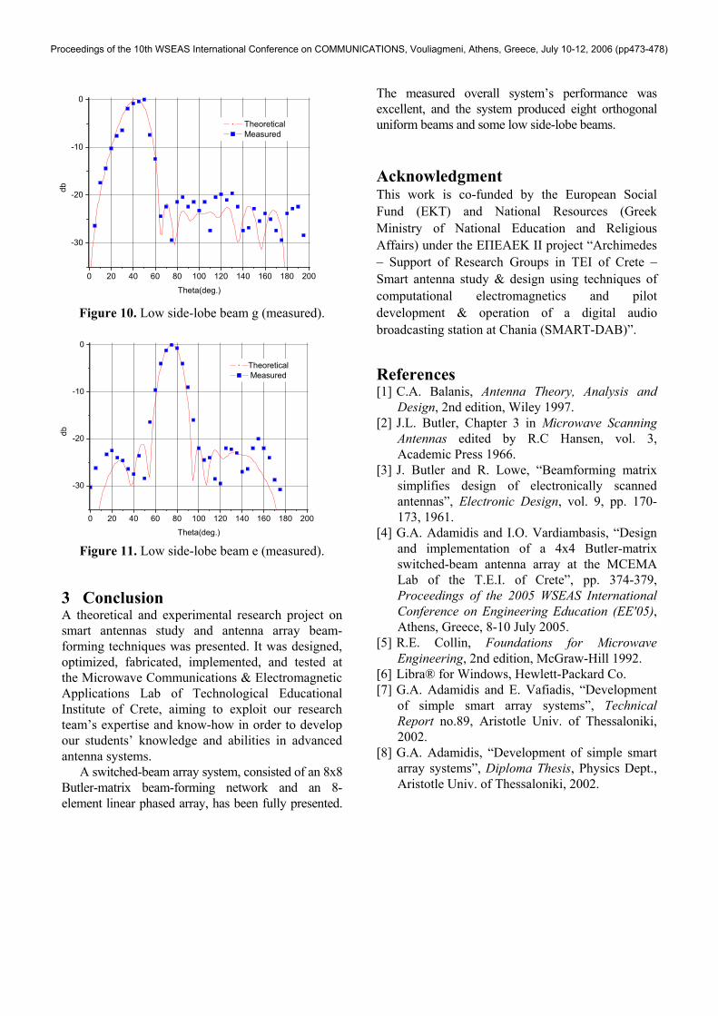
Figure 10. Low side-lobe beam g (measured).
Figure 11. Low side-lobe beam e (measured). 3 Conclusion A theoretical and experimental research project on smart antennas study and antenna array beam-forming techniques was presented. It was designed, optimized, fabricated, implemented, and tested at the Microwave Communications & Electromagnetic Applications Lab of Technological Educational Institute of Crete, aiming to exploit our research team’s expertise and know-how in order to develop our students’ knowledge and abilities in advanced antenna systems. A switched-beam array system, consisted of an 8x8 Butler-matrix beam-forming network and an 8-element linear phased array, has been fully presented.
The measured overall system’s performance was excellent, and the system produced eight orthogonal uniform beams and some low side-lobe beams. Acknowledgment This work is co-funded by the European Social Fund (ΕΚΤ) and National Resources (Greek Ministry of National Education and Religious Affairs) under the ΕΠΕΑΕΚ ΙΙ project “Archimedes – Support of Research Groups in TEI of Crete – Smart antenna study & design using techniques of computational electromagnetics and pilot development & operation of a digital audio broadcasting station at Chania (SMART-DAB)”. References [1] C.A. Balanis, Antenna Theory, Analysis and
Design, 2nd edition, Wiley 1997. [2] J.L. Butler, Chapter 3 in Microwave Scanning
Antennas edited by R.C Hansen, vol. 3, Academic Press 1966.
[3] J. Butler and R. Lowe, “Beamforming matrix simplifies design of electronically scanned antennas”, Electronic Design, vol. 9, pp. 170-173, 1961.
[4] G.A. Adamidis and I.O. Vardiambasis, “Design and implementation of a 4x4 Butler-matrix switched-beam antenna array at the MCEMA Lab of the T.E.I. of Crete”, pp. 374-379, Proceedings of the 2005 WSEAS International Conference on Engineering Education (EE'05), Athens, Greece, 8-10 July 2005.
[5] R.E. Collin, Foundations for Microwave Engineering, 2nd edition, McGraw-Hill 1992.
[6] Libra® for Windows, Hewlett-Packard Co. [7] G.A. Adamidis and E. Vafiadis, “Development
of simple smart array systems”, Technical Report no.89, Aristotle Univ. of Thessaloniki, 2002.
[8] G.A. Adamidis, “Development of simple smart array systems”, Diploma Thesis, Physics Dept., Aristotle Univ. of Thessaloniki, 2002.
0 20 40 60 80 100 120 140 160 180 200
-30
-20
-10
0
db
Theta(deg.)
Theoretical Measured
0 20 40 60 80 100 120 140 160 180 200
-30
-20
-10
0
db
Theta(deg.)
Theoretical Measured
Proceedings of the 10th WSEAS International Conference on COMMUNICATIONS, Vouliagmeni, Athens, Greece, July 10-12, 2006 (pp473-478)