Embed Size (px)
Citation preview

taoxbECpE
12/1/20112011
Smart Civil Infrastructure Monitoring Design Document (May12-26)
Iowa State University
EE 491
Project Client Laflamme Simon
Facility AdvisorRandall Geiger
Project Team:
Xianbo Tao (Electrical Engineering)Kun Zhang (Electrical Engineering)Guoyan Kai (Electrical Engineering)
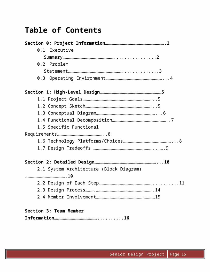
Table of ContentsSection 0: Project Information………………………………………………………….2
0.1 Executive Summary…………………………………………………................20.2 Problem Statement……………………………………………………..............30.3 Operating Environment………………………………………………………...4
Section 1: High-Level Design……………………………………………………………5 1.1 Project Goals…………………………………………………………………...5 1.2 Concept Sketch………………………………………………………………...5 1.3 Conceptual Diagram…………………………………………………………...6 1.4 Functional Decomposition……………………………………………………..71.5 Specific Functional Requirements……………………………………………..81.6 Technology Platforms/Choices………………………………………………...8 1.7 Design Tradeoffs …………………………………………………………...….9
Section 2: Detailed Design……………………………………………………………...10 2.1 System Architecture (Block Diagram)……………………………………….10 2.2 Design of Each Step……………………………………………………..........11 2.3 Design Process……….……………………………………………………….14 2.4 Member Involvement…………………………………………………………15
Section 3: Team Member Information…………………………………………..........16
Page 1Senior Design Project

0.0 Project Information
0.1 Executive Summary
Inspection and monitoring to public civil infrastructures in the country is a big issue in order to prevent catastrophes to the public. Smart monitor systems have now been popular across the country. Dr. Simon Laflamme joining the faculty at Iowa State University in the Department of Civil and Construction Engineering Department brought up a new plan to design a monitor system to detect the condition of bridge. The capacitive seniors play an important role in this project. Under the direction of Professor Randy Geiger, the senior design group is expected to design a circuit that works with capacitive sensors. The output data are linked to ADC of the communication system to the cell phone.
Page 2Senior Design Project

0.2 Problem Statement
There is considerable concern about the long-term safety of the aging civil infrastructures in the country. This concern relates to bridges, buildings, public transportation and public utility systems such as conventional and nuclear power plants. Monitoring or inspection to identify potential problems and prevent catastrophic failures is one way to help mitigate the growing concerns.
In this project we will focus on the development of a smart civil infrastructure monitoring system. This system will use state of the art stress sensors and wireless communications to provide real-time stress data to a WEB-accessible database that can be regularly monitored to detect potential problems. This project will be supervised by Professor Randy Geiger in consultation with faculty members in the Department of Civil and Construction Engineering who are working on the development of new sensors and their application in smart civil infrastructure modeling.
One sensor that will be used is a soft capacitive membrane sensor that was recently introduced by Dr. Simon Laflamme as part of his doctoral work at MIT prior to joining the faculty at Iowa State University in the CCE Department. Strain-gage type sensors will also be considered. In addition to applying these sensors to physical members in structures such as bridges, application of sensors to the blades of wind turbans will be considered. In this latter application, energy harvesting will be considered as a means of powering a wireless communications interface that transmits stress data to an intermediate node which will subsequently use wireless transmission for connection to the WEB-accessible interface.
Page 3Senior Design Project

0.3 Operating Environment
There has a bridge Make all the equipment in same moisture, sunshine, temperature. Accessibility to supply power Cell phone signal accessible
First of all, our project main goal is to ensure the safety of the bridge, so we must have a bridge to complete our project.
Secondly, some capacitors, resistors and some other equipment are highly dependent on the temperature or environmental factors. So, if they are not in the same situation, the data we get will not accurate.
Finally, we need a supply power to make sure the circuit works. In most places, we will have cell phone signal for sure.
Page 4Senior Design Project

1.0 High-Level Design
1.1 Project Goals
Design circuit for small changes in capacitors Analyze system reliability Lower cost demand Test the system stability to environment
1.2 Concept sketch
The entire system is made up by an array of capacitors, wireless communication transmitter, a receiver such as cell phone. The array of capacitors which is attached to is designed to detect the stress of the bridge.
Our project’s goal will mainly on the use of these capacitors to collect data. Each capacitor will compare with its neighbor by subtraction when it encounters stress; and the delta-capacitor function is determined by its intrinsic property from manufacture, temperature, and stress.
Instead of approaching to a bridge, we will set up an equivalent model in lab to test the stress-capacitor function. 200pf capacitor will be used and a switch connected to 2pf
Page 5Senior Design Project

capacitor as delta-capacitor due to stress by just turning on or off the switch to make same effect as the capacitor encounters stress. When the capacitor changes too much that exceed stress the bridge undertakes, this circuit will output a voltage varied with the capacitor change. The voltage change will be transmitted to ADC; then a detector will store the ADC data and send a warning to user’s cell phone wireless.
1.3 Conceptual Diagram
1.4 Functional Decomposition
Page 6Senior Design Project

Overall Function The smart civil infrastructure monitoring system is used to detect whether the crack or broken point happened on the bridge or not. A detector will store the stress data and analyze the data when the data reflect the bridge in danger, the system will send a warning to user’s cell phone wireless.
Sub-functions Many pieces of soft capacitors are stickled under the bridge. If there is crack
existing on the bridge, it will stress the soft capacitors so that the capacitance of some stages will change somehow.
A transmitter is connected to the outputs of capacitors system to save and analyze the data.
The circuit designed for capacitive sensors has a function to take subtraction of capacitors so that the location of the capacitors changed can easily be found. Differential amplifiers play an essential role in the design.
The real-time stress data reflect delta function of capacitance, which will be analyzed by a microcontroller. A program is made to deal with the data and interface with hardware.
The WEB-accessible database can be regularly monitored to detect potential problems. All the date in the database will be translated into microcontroller system.
A receiver such as a cellphone or computer will pick up the signal by radio. And Cellphone will get the message that the bridge needs to be maintained from computer. Some professional bridge constructors will go to the bridge where crack happened.
1.5 Specific Functional Requirements
Page 7Senior Design Project

Different types of phone will not affect the entire communication.
The interface is supposed to require little technical experience which makes common
people to operate.
Capacitive sensors shall overcome the interruption of other natural force such as wind
and rain just collecting data from condition of bridge.
The wireless network should be reliable and stable to send data to the user constantly.
The communication companies such as T-Mobile do not affect the network.
The transmitter shall have sufficient defense to protect itself working in an urban and
rural environment. The weather change will not affect its function.
Some factors such as its intrinsic property from manufacture, temperature, and stress
will affect the value of capacitors
The duration of the transmission from the microcontroller to cell phone should take too much time.
1.6 Technology Platforms/Choices
A high frequency microcontroller will play an essential role in the data conversion and analysis, since it has ADC and DAC and transmit the signal very fast and reliably. This is a senor that can detect the flaw of the bridge. The senor is made of a kind of capacitor, then we arrange some numbers of capacitors under the bridge, and the detail locations are chosen by the instructor. We probably need to add our product to the each new built bridge and I think even better for the bridge which is looks old or dangerous. Since the capacitors’ property has something relationship with temperature, and some other weather factor, so we should make sure our capacitors in some safe place, and make them work properly. The user provided with a cell phone will be informed of the current condition of the bridge, and information will contain the warning message if the bridge is on the edge of danger. The cell phone will pick up the data from the transmitter that showing the strain-gage type sensors information. Then we should get signals for our device, if our device can’t transmit signal back to the person, our work is useless.
1.7 Design Tradeoffs
Page 8Senior Design Project

The main conflict in our project is to design the circuit by ourselves, or purchase a product that can measure small change of the capacitors. Implementation of parts purchased can obtain accurate and reliable outputs but high expense must be paid, while the circuit building up by basic electronic elements may not work well or as expected. Parts from the lab kits may not reach standards expected. Different types of parts are needed to meet the performance required. Some parts implemented to the entire system may function ineffectively.
It is impossible to find two same capacitors in lab. Usually they have some difference due to manufacturing difference, so these two capacitance should be compensated to make them same when design the circuit. Since the two capacitors at the terminal change very small, manufacturing difference will not affect the real change due to the stress of the bridge.
2.0 Detailed Design2.1 System Architecture
Page 9Senior Design Project

This is the overall block diagram for our project; we put 16 soft capacitors under the bridge with specified locations. If the crack happens on the bridge, the capacitances of the capacitors will change, and our design can identify the location where the crack happens, then we will have the data we need, Bluetooth can send these data to PC or cellphone, then then constructor will make some change.
2.2 Design of Each Step
Our design has been broken down into several different steps
Goal
Page 10Senior Design Project

We want to get the difference of the capacitors with the specific locations, when the crack happens, then through microcontroller, we can get the signal.
The Design Circuit
This is a circuit design for the stress sensor. And C1 and C2 are the capacitor sensors. Actually we have 16 capacitor sensors attach under the bottom of a bridge. This time, we just need to study in the relationship of two capacitors. Then we will do the same measurement for other 14 capacitor sensors. Basically, C1 and C2 represent two different positions. And if crack happens on the bridge in position C1, the capacitance of C1 will change a little bit. So the corresponding output will shows the changes.
The Testing Results If there is no crack happen on the bridge
Page 11Senior Design Project
The horizontal axis is time, the vertical axis is voltage, and the green line represents voltage increase from 0v to 80v with time shifts. The red line is the output voltage. At this time, we find when the bridge is safe; we will have a voltage output equal to 0V.
If the crack happens on the position of C1
We will find we input voltage is more than 20V. Then we can easily find out the output is larger than 0 apparently.
Transmit the data into signal
Page 12Senior Design Project

We have the output result, because we have AC input. And if we want to get data, we have to convert analog signal into digital. Next step is to pass through ADC converter.
Then we have the data we need, and we just transmit our data to client’s cell phone or desktop. Actually, the companies like Verizon and AT&T both can do the job send the data to cell phone or client’s desktop.
Page 13Senior Design Project

2.3 Design Process
Phase 1: Problem Identify
Description: We need to know how to detect the crack happen on the bridge. And we are given some soft capacitors. We need to use these soft capacitors to identify the problems.
Goal: A good circuit to precisely detect the crack.
Completion: Oct 25, 2011
Phase 2: Design Circuit
Description: There are so many ways to design a circuit, and we are given the best and most precise way is to measure the differential capacitance.
Goal: A precise way to detect the crack.
Completion: Nov 8, 2011
Phase 3: The Process of the Design
Description: When we are on the way to design the circuit, our goal is to invent a circuit doing the measurement of the differential capacitance.
Goal: Choose the best circuit
Completion: Nov 20, 2011
Phase 4: Analog to Digital Converter
Description: This part is very common device; we just need to buy it.
Goal: Convert analog signal into digital signal
Completion: In progress
Page 14Senior Design Project

Phase 5: Transmit the Signal into Micro-Controller
Description: We have to implement the micro-controller based on the C language program, which transfer the output signal from ADC to wireless transceiver
Goal: Convert digital signal into micro-controller in order to send message.
Completion: In progress
Phase 6: Transmit the Signal to the Cellphone
Description: The transceiver will send a message to cellphone. We have to let the officer to know there is some problem on the bridge; they must go to do some maintain.
Goal: Notify the constructor to fix repair the crack
Completion: In progress
2.4 Member Involvement
Page 15Senior Design Project

3.0 Team Member Information Faculty Advisor: Dr. Geiger Randall L Professor Electrical and Computer Engineering 2133 Coover Ames, IA 50011-3060 515-294-7745Email: [email protected]
Client: Laflamme Simon416A Town Engr Ames, IA 50011-3232515-294-3162Email: [email protected]
Team Members: Xianbo Tao (Team Leader)
1300 Coconino Rd Unit 226Ames, IA 50014-7884
515-708-8221
Email: [email protected]
Guoyan Kai (Communicator)
156 University Vlg Apt BAmes, IA 50010
515-203-1642
Email: [email protected]
Kun Zhang (Website Leader)
3319 Story St Unit 201Ames, IA 50014-3437
515-441-0597
Email: [email protected]
Page 16Senior Design Project