Embed Size (px)
Citation preview

Volume XXI 2018
ISSUE no.1
MBNA Publishing House Constanta 2018
doi: 10.21279/1454-864X-18-I1-075 SBNA© 2018. This work is licensed under the CC BY-NC-SA 4.0 License
SBNA PAPER • OPEN ACCESS
Smart Plant Energy Control using IoT Technology To cite this article: Sorin R. Sintea, Valetina M. Pomazan and Cătălin C. Pomazan, Scientific Bulletin of Naval Academy, Vol. XXI 2018, pg. 509-517.
Available online at www.anmb.ro
ISSN: 2392-8956; ISSN-L: 1454-864X

Smart Plant Energy Control using IoT Technology
Sorin R. Sintea1, Valetina M. Pomazan
2, Cătălin C. Pomazan
3
1, 3 Maritime University of Constanța, 41, 1 Decembrie 1918 blvd, România 2Ovidius University of Constanța, 124 Mamaia, 900527 Constanța, România [email protected], [email protected], [email protected]
Abstract. In the new era, the monitoring and control of electricity production and consumption in a factory remain important objectives. Following the emergent Industry 4.0 paradigm, plants and manufacturing companies shift to a new development strategy of automation. We present a solution and the supporting technology to create a factory network infrastructure for monitoring and optimizing the electrical power consumption using Kaa IoT technology for data transfer and infrastructure configuration.
1. Introduction. Dynamic Energy Monitoring and Control using Cloud Technology Digital manufacturing is a virtual representation of the entire manufacturing process so that
designers can make better choices about materials and processes. The biggest challenge in adopting digital manufacturing for small and medium enterprises is the concern regarding safety. With the rapid development of cloud computing concept and technologies, more and more cloud-based business models and practical applications are emerging in industrial environments, including cloud manufacturing and cloud logistics. Such cloud systems integrate the distributed resources and make best use of them to fulfill dynamic tasks in an optimal way.
A basic need is the possibility to access data and information from different type of devices (numerical controlled machines and processes, computers, notebooks, tablets or phones). The challenge is to integrate the variety of producers with their own data accessing interfaces and their own security and data protection protocols.
The emerging small and medium size manufacturing companies impose a business strategy and request a standard presentation mode of the data accessed by any operator. A standard interface for data communication between all systems is needed, along with the possibility to focus all the data for centralized analysis.
The new developed IoT (Internet of Things) technology offers the possibility to concentrate all the systems and to monitor and analyze all data flux in real time. The IoT technology infers the existence of a cloud based IoT server where will be sent all the data from the monitoring and control subsystems. Also we need a tool for data analysis (like big-data analysis tool) and a module for data presentation.
Challenges and barriers have prevented the adoption of smart manufacturing technologies. One of them is the issue of control, protection and security of data, along with the restraint or even refusal to export data in private Internet Clouds. This paper analyses a solution to create personalized cloud, installed at the company site, where all equipment and software programs needed to implement an IoT solution will be stored.
The term “smart manufacturing” has been adopted to refer to manufacturing systems that combine advanced manufacturing capabilities and digital technologies throughout the product lifecycle. Such systems are characterized by improvements in communication with other systems across the network, collection and response to operational data, support for decision making, increased specialization to accommodate advanced materials. Moreover, each component of a smart manufacturing system may contain all of these capabilities, for a particular function and thus can be considered a smart manufacturing system in itself.
Smart manufacturing incorporates many of the historical manufacturing paradigms that have been the focus of research and practitioner efforts to improve manufacturing practices, as lean, flexible, agile, sustainable, digital, and cloud manufacturing. Smart manufacturing can enable aspects of these paradigms for all manufacturers from small businesses to large enterprises [3].
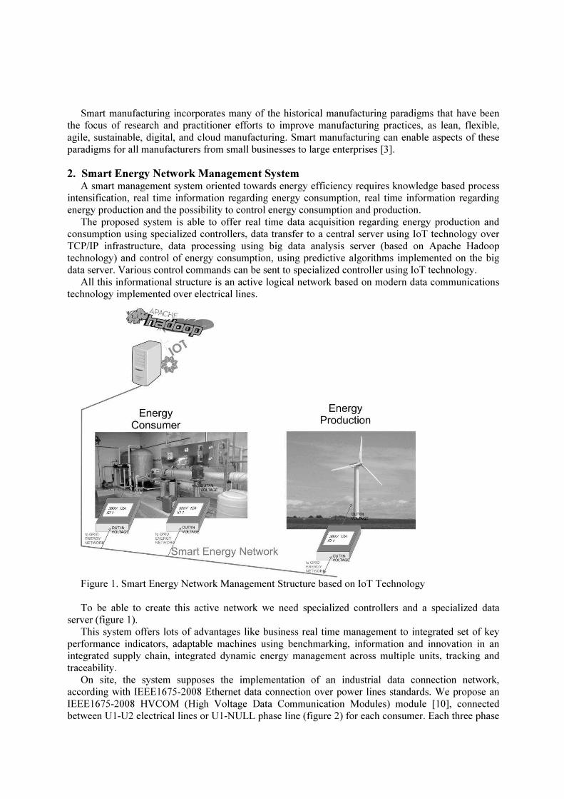
2. Smart Energy Network Management System A smart management system oriented towards energy efficiency requires knowledge based process
intensification, real time information regarding energy consumption, real time information regarding energy production and the possibility to control energy consumption and production.
The proposed system is able to offer real time data acquisition regarding energy production and consumption using specialized controllers, data transfer to a central server using IoT technology over TCP/IP infrastructure, data processing using big data analysis server (based on Apache Hadoop technology) and control of energy consumption, using predictive algorithms implemented on the big data server. Various control commands can be sent to specialized controller using IoT technology.
All this informational structure is an active logical network based on modern data communications technology implemented over electrical lines.
Figure 1. Smart Energy Network Management Structure based on IoT Technology To be able to create this active network we need specialized controllers and a specialized data
server (figure 1). This system offers lots of advantages like business real time management to integrated set of key
performance indicators, adaptable machines using benchmarking, information and innovation in an integrated supply chain, integrated dynamic energy management across multiple units, tracking and traceability.
On site, the system supposes the implementation of an industrial data connection network, according with IEEE1675-2008 Ethernet data connection over power lines standards. We propose an IEEE1675-2008 HVCOM (High Voltage Data Communication Modules) module [10], connected between U1-U2 electrical lines or U1-NULL phase line (figure 2) for each consumer. Each three phase

consumer is connected using a circuit power breaker to the power lines. Each HVCOM module is
connected using MII-BUS with electronic module MII-DATASW (or IoT GATEWAY). This module
connects data network with an Internet network. The module is an IoT Gateway over TCP/IP (using
IPv4 protocol or IPv6) linked with Internet through Ethernet line using IEEE 802.3 DATACOM
Industrial Ethernet adapter, connected over MII LINE5. DATACOM module must ensure the high data
rate (using a minimum 300Mbps in standard mode in accord with IEEE1675-2008, the actual rate
obtained is about 500 Mbps in local area). The IoT GATEWAY implemented is based on KAA
Gateway [7] using Microchip’s ATSAMA5D28 [8]. The IoT GATEWAY uses a Linux CentOS 7
operating system with Kaa IoT Gateway software [7]. This equipment will be configured to be
connected with the power plant IoT Server.
Figure 2. Digital Network Gateway installed in electrical power panel
The IoT Server is installed in the power plant data center on a Linux CentOS 7 Operating System.
The IoT Server software is based on Kaa IoT Server solution. To be accessed from Internet the IoT
Server is connected to the Internet using IEEE-1682-2011 optical fiber communication standards. We
recommend this high speed data connection because the IoT system requires high speed and high data
bandwidth for IoT applications. Also it is recommended to have two high rate data connection between
the IoT server and the Internet to be able to ensure a permanent access connection from Internet. The
IoT server can be combined with Apache cloud technology and can be duplicated in the cloud to
ensure a high availability solution for IoT data structure. The second IoT server is installed in a
clustered architecture on a Linux CentOS7 machine using Apache CloudStack technology.
3. Smart Energy Controller
The Smart Energy Controller is the key of the new Smart Energy Network. The controller
(INVERTER-4Q) is able to connect with three phase AC on internal electrical energy grid and the
output can be connected to a three phase or single phase consumer or with a three phase power grid.
The controller is able to control energy flow and power transferred between energy grid and consumer,
optimizing the energy flux and it is able to disconnect the consumer from the power source in case of
idle mode. All this facilities can be obtained using efficient programmed algorithms implemented in

the IoT server. The controller (INVERTER-4Q) connects the consumer and power lines directly
(figure 3a) or its signaling system can be interfaced with industrial consumer automation systems
(figure 3b). In the latter case, the consumer protection signal is connected with CT-IN input of the
INVERTER-4Q and the signal CT-OUT (of the INVERTER-4Q) is programmed as power good signal
is connected to power-on signal of the consumer side.
a)
b)
Figure 3. Connection of consumer with electrical power line using grid power control inverter
The controller consists of the following modules (figure 4) [1]:
• specialized controller for energy data measurement in real-time in four quadrants
• specialized data communication controller over electrical power lines using TCP/IP with a
300Mbps data communication bandwidth
• specialized controller for IoT communication and data control using Kaa-client solution over
Ethernet TCP/IP Network Standards
Figure 4. Logical structure of electrical power grid controller
The main schematic of the controller is based on two three phase inverters AC/DC or DC/AC
(figure 5) BINV_1 and BINV_2, each inverter having independent controlled power transfer modes.
The electric power circuit between the two inverters is a DC circuit. The inverters are programmed to
work in associated mode, by default when BINV_1 is in rectifier mode (from AC to DC) then BINV_2
operate in inverter mode (from DC to AC) and, in case of we have the electrical producer as consumer,
BINV_2 is operate in rectifier mode (from AC to DC) and BINV_1 operate in synchronized inverter
mode (the energy will be delivered through BINV_1 from DC circuit to power source line). In DC
circuit a C1/250uF power capacitor is used for filtering switching pulses and to accumulate energy for
the power inverter. Also a controlled power dissipation circuit is used, consisting of resistor R1 and the
power MOSFET transistor M1 controlled by a PWM unit (CISO), unit controlled by IoT-CONTROL-
UNIT through third I2C communication bus. Depending on R1 value, one can obtain miscellaneous
values for controlled power dissipated (in this schematic the maximum dissipated current is about 1A).

Figure 5. The electrical bloc schematic of electrical power grid controller INVERTER-4Q
The inverter operating mode is controlled by the IoT controller IoT-CONTROL-UNIT. This unit is
programmed to control activity of both BINV_1 and BINV_2 units. The communication between IoT-
CONTROL-UNIT and inverter modules is implemented using I2C bus architecture. Also the unit
communicates with IoT server through the communication unit which delivers to the IoT server the
following data:
• the electrical parameters for both converters (BINV_1, BINV_2) - voltage, current, power,
power factor i.e.
• the operation mode of both converters (BINV_1, BINV_2) - rectifier, inverter, synchronized
inverter
• the power dissipated on R1 circuit - voltage, current, power
• the errors and functional status of unit
The unit receives the following signals and values from IoT server for controlling the unit operating
mode:
• the consumer electrical parameters (BINV_2 output parameters); the maximum power
consumed/injected (BINV_1 input parameters); the minimum electrical parameters (current,
power, power consumed in 15 min); an unit operation mode (the unit connects a consumer, the
unit connects a power generator, the unit is able to control a controlled asynchronous drive,
synchronous drive, DC drive, electrical lamp i.e.); the ON/OFF control for the unit; a TEST
mode signal
The control unit (IoT-CONTROL-UNIT) is created using Microchip’s ATSAMA5D28
processor [8]. The unit is implemented using Linux CentOS7 and Kaa-IoT client software. Also the
unit is connected with the network using IEEE1675-2008 HVCOM (High Voltage Data
Communication Module) [9, 10]. The controller will communicate with HVCOM unit using high
speed MII bus.
The Inverter unit is based on a BLOCCONTROL unit module and hex power HEXMOS-FET
Transistors Bridge (or IGBT Bridge) [1].

Figure 6. The block schematic of the power inverter BINV
The HEXMOS-FET bridge is implemented using Semikron’s SKiiP-13ACM12V17 [2]. The
BLOCCONTROL unit drives the power transistor bridge operation mode in according with functional
control mode. This unit can be controlled over I2C bus from IoT-CONTROL-UNIT. The unit can
operate in three modes:
• controlled rectifying mode
• inverter mode
• synchronized controlled inverter mode
In controlled rectifying mode the transistor bridge operates as a full controlled rectifying bridge
which will convert the input three-phase AC input voltage in DC output voltage. The transistors bridge
are synchronously activated, in according with input AC voltage and the power request from DC
circuit to maintain a constant voltage on output. To be able to perform this task, the BLOCCONTROL
will read input voltages (U1, U2 and U3), output DC voltage (U0) and output current (I). The operation
control unit implements control function Fr:
Fr = F(U1(t), U2(t), U3(t), U0(t), I(t), t)
and for transistor block protection the controller must check the output current I(t) and currents on each
input( I1(t), I2(t), I3(t)). In inverter mode the transistor bridge operates also in inverter mode, by
converting the U0 input DC voltage in three phase AC voltage (U1, U2, U3). The output voltages are
sinusoidal signals generated in according with:
U1(t) =U0 . sin (2 . PI . f . t )
U2(t) =U0 . sin (2 . PI . f . t + 2 . PI / 3) (1)
U3(t) =U0 . sin (2 . PI . f . t + 4 . PI / 3),
where f is the output signal frequency (it can be 50Hz or 60Hz in accord with the programmed value).
The controller corrects the transistors activation in according with the current absorbed by each phase
(I1, I2, and I3). The system protection is controlled by the input current I0 and the outputs currents I1,
I2, I3. Another important mode is to control the power transferred from the DC circuit to AC three
phase output circuits. This mode is named “synchronized controlled inverter mode” when the inverter
output power is the AC three phase electrical lines and the input power is obtained from DC current
circuit. In this mode the output signal must inject current in three phase AC electrical circuit. The
monitored generated signal is:
U01(t) =U0 . sin (2 . PI . f . t + fi1)
U02(t) =U0 . sin (2 . PI . f . t + fi2) (2)
U03(t) =U0 . sin (2 . PI . f . t + fi3),
where f is output signal frequency (it can be 50Hz or 60Hz in accord with the programmed value) and
fi1, fi2 and fi3 are initial phases of three phase electrical system (U1, U2, U3). The controller corrects

the transistors activation in accord with the current absorbed by each phase (I1, I2, I3) and initial phases of the three phase electrical system (fi1, fi2, fi3). The system protection is controlled by the input current I0 and the output currents I1, I2, I3.
For thermal protection a BLOCCONTROL is monitoring the RT1 thermistor, mounted in the transistor block. In case of heating of the transistor block the BLOCCONTROL will disable activity of the current transistor block and send two messages to the IoT-CONTROL-UNIT. The controller of the IoT-CONTROL-UNIT can disable the activity of both inverters.
The BLOCCONTROL controller is programmed using the Kaa-client connector to the Kaa-Server using Linux GNU C compiler. For creating of a Kaa-client a Kaa-User has to be created in Kaa-IoT Server architecture. To enable communication a MyPlant-User IoT user is also created on Kaa IoT server. This user will be augmented with the four controllers (MyBC1, MyBC2, MyBC3 and MyBC4) and one gateway that connect the controller and the server (MyGW). For the application control a data binding architecture on IoT server for the given user (MyPlant-User) needs to be created (Table 1):
Table 1. Data binding architecture
No Data field name Data type Field Security
1 index int ReadOnly
2 mode int ReadWrite
3 enable int ReadWrite
4 power float ReadWrite
5 frequency float ReadWrite
6 DC_Voltage float ReadWrite
7 DC_Power float ReadWrite
8 BINV_1_mode int ReadOnly
9 BINV_1_status int ReadOnly
10 BINV_1_enable int ReadOnly
11 BINV_1_U01 float ReadOnly
12 BINV_1_U02 float ReadOnly
13 BINV_1_U03 float ReadOnly
14 BINV_1_U1 float ReadOnly
15 BINV_1_U2 float ReadOnly
16 BINV_1_U3 float ReadOnly
17 BINV_1_I1 float ReadOnly
18 BINV_1_I2 float ReadOnly
19 BINV_1_I3 float ReadOnly
20 BINV_1_U0 float ReadOnly
21 BINV_1_I0 float ReadOnly
22 BINV_1_RT float ReadOnly
23 BINV_2_mode int ReadOnly
24 BINV_2_status int ReadOnly
25 BINV_2_enable int ReadOnly
26 BINV_2_U01 float ReadOnly
27 BINV_2_U02 float ReadOnly
28 BINV_2_U03 float ReadOnly
29 BINV_2_U1 float ReadOnly
30 BINV_2_U2 float ReadOnly
31 BINV_2_U3 float ReadOnly
32 BINV_2_I1 float ReadOnly
33 BINV_2_I2 float ReadOnly
34 BINV_2_I3 float ReadOnly
35 BINV_2_U0 float ReadOnly
36 BINV_2_I0 float ReadOnly
37 BINV_2_RT float ReadOnly

In the table 1, the fields are as following:
• “index” is the record input in IoT data base on server (the value is a data auto-generated)
• “mode” selects the inverter operation mode (normal consumer, power controlled consumer, protected consumer, normal generator, power controlled generator, protected power line, AC/DC inverter, asynchronous drive control, synchronous drive control, DC current drive control, auto connected consumer)
• “enable” field, enables activity of inverter
• “power” field represent the power transferred through inverter
• “frequency” is the input/output frequency of inverter
• “DC_Voltage” field represents the value of voltage in DC intermediate circuit
• “DC_Power” field represents the value of power programmed to be transferred through the DC intermediate circuit
• “BINV_1_mode”, “BINV_2_mode” fields represent the BINV_1, BINV_2 inverter modes (rectifier, inverter or synchronized inverter modes)
• “BINV_1_status”, “BINV_2_status” fields represent the BINV_1, BINV_2 inverter status (active, inactive, error)
• “BINV_1_enable”, “BINV_2_enable” fields represent the enable signals for each inverter (on or off)
• “BINV_1_U01”, “BINV_1_U02”, “BINV_1_U03” are voltages reads from input electrical power line
• “BINV_2_U01”, “BINV_2_U02”, “BINV_2_U03” are voltage readings from consumer electrical power line
• “BINV_1_U1”, “BINV_1_U2”, “BINV_1_U3” are voltage readings from the input of BINV_1 inverter and “BINV_2_U1”, “BINV_2_U2”, “BINV_2_U3” are voltage readings from three phase connections of BINV_2 inverter
• “BINV_1_I1”, “BINV_1_I2”, “BINV_1_I3” are current readings through AC lines of BINV_1 inverter and “BINV_2_I1”, “BINV_2_I2”, “BINV_2_I3” are current readings through AC lines of BINV_2 inverter
• “BINV_1_U0”, “BINV_1_I0” and “BINV_2_U0”, “BINV_2_I0” are the voltages and currents in DC circuits of BINV_1 inverter and BINV_2 inverter
• “BINV_1_RT” and “BINV_2_RT” are the values of temperature measured on transistor block of BINV_1 inverter and BINV_2 inverter
All these values are processed in the IoT-CONTROL-UNIT unit controller of the inverter and the data is synchronized with BLOCCONTROL controller in each BINV_1 and BINV_2 inverters. The main control algorithm is implemented in the IoT-CONTROL-UNIT controller.
4. Smart Energy Server using IoT Technology and Big Data Analysis Server
All data measured by the smart energy controller creates an informational data flux of measured energy and this flux will be routed to the IoT data server. The IoT data server is implemented on a clustered Embedded server. Each cluster is implemented on a Linux machine using RedHat Cluster technology (implemented in CentOS 7). In the cluster are encapsulated both data storage and applications. Each application has its own cluster, independent to the other ones. Each cluster will store data into a SQL (Apache Cassandra) or NoSQL (Apache CouchDB) database using Apache technologies. The both solutions are using mission critical database servers. For IoT cluster solution we intend to use KaaIoT server from KaaIoT Technologies LLC. All IoT servers and clusters can be distributed on a Linux Fedora machine. All data flux is analyzed by Apache Hadoop big data analyzer software which is containerized in a cluster. For implementation we choose an HPE ProliantMicroserver Gen10 with two physical core Xeon processors architecture. For virtualization a VMWarevSphere Hypervisor will be used.

Figure 7. The general Architecture of an IoT network server
5. Conclusion
The study presented in this paper explores the design of an IoT based framework for electronics
manufacturing involving the use of VR based environments and Cloud computing technologies. The
process domain of interest is electronics manufacturing with an emphasis on Surface Mount assembly
of printed circuit boards (PCBs). The VR based assembly environment played a key role in this IoT
framework as it supported Concurrent Engineering practices by enabling stakeholders in this
manufacturing system context, to obtain a better understanding of the manufacturing process design
while providing ‘what if’ analysis capabilities for changing customer requirements. Another benefit of
such VR based IoT frameworks is the potential of such 3D environments to provide effective training
of assembly processes as well as facilitating better understanding of process design issues from
distributed locations.
References
[1] Dr.Ing. Arendt Wintrich, Dr.-Ing. Ulrich Nicolai, Dr. techn. Werner Tursky, Univ.-Prof. Dr. Ing.
Tobias Reimann, Application Manual Power Semiconductors, SEMIKRON International
GmbH, ISLE Verlag 2015, ISBN: 978-3-938843-83-3.
[2] ***, Power Electronics 2017-2018, SEMIKRON International GmbH, ISLE Verlag 2017.
[3] Dave Evans, The Internet of Things How the Next Evolution of the Internet Is Changing
Everything, April 2011
[4] https://github.com/RIOT-OS/RIOT/wiki/Introduction, March 2018
[5] Saminath.V, Internet of Things using RIOT and KAA software platform on AT9186 Radio
Interface, International Journal of Scientific and Research Publications, Volume 6, Issue 8,
August 2016, ISSN 2250-3153
[6] https://www.kaaproject.org/overview/, March 2018
[7] https://www.kaaproject.org/platform/#gate, March 2018
[8] http://ww1.microchip.com/downloads/en/DeviceDoc/DS60001476B.pdf, 32-BIT ARM-BASED
MICROPROCESSORS SAMA5D2 Series SAMA5D21 /22 /23 /24 /26 /27 /28, DS60001476B,
Microchip Technology Inc, 2017
[9] Lutz Lampe, Andrea M. Tonello, Theo G. Swart, Power Line Communications: Principles,
Standards and Applications from Multimedia to Smart Grid, John Wiley & Sons, 14 apr. 2016
[10] https://www.tp-link.com/ro/products/details/cat-18_TL-PA8030P-KIT.html, March 2018