Embed Size (px)
Citation preview

Specifications are subject to change without notice. “This product is designed for general industrial use.”
OVERVIEWModel HLC Small-Port Cage Guide Type Single Seated Con-trol Valves are designed for high differential pressure Service where fluid normal differential pressure exceeds 2940 kPa {30 kgf/cm2} or for heavy-duty service where flashing/cavitation may occur. Further, they are ideal for preventing erosion from the valve body, because their guides are sturdy and the valve body is protected by a cage. The compact valve body, having an S-shaped flow passage that features low pressure loss, allows a large flow capacity and rangeability.The valve plugs are available in a wide range of Cv values. The flow shutoff performance complies with simplest mech-anisms, utilizes a compact yet powerful diaphragm actuator loaded with multiple springs.The model HLC Control Valves are widely applicable for reliable control of small flows in high- or low-temperature, high differential pressure process lines.Model HLC is compliant to Functional Safety Standard (IEC61508).
SPECIFICATIONSBody
TypeStraight-through, cast globe valveNominal size1/2, 3/4, 1 inch Pressure rating and End connection
Connection type Pressure rating Applicable standard
FFJIS10K JIS B2210-1984ANSI Class 125 ANSI B16.5-1981JPI Class 125 JPI-7S-15-1993
RFJIS10K, 16K, 20K, 30K, 40K JIS B2210-1984ANSI Class 150, 300, 600 ANSI B16.5-1981JPI Class150, 300, 600 JPI-7S-15-1993
RJ, LGANSI Class 150, 300, 600 ANSI B16.5-1981JPI Class 150, 300, 600 JPI-7S-15-1993
Tongue and groove(groove)
Male and female(female)JIS16K, 20K, 30K, 40K JIS B2202-1984
• Welded end: SW , BW
MaterialsFor body/trim material combinations and operating temperature ranges, refer to Table 1.Bonnet
Plain bonnet -17 to 230 °C -
Extension bonnet Type 1-45 to -17 °C 230 to 566 °C
-
Extension bonnet Type 2-100 to -45 °C Integral-cast type
-196 to -100 °C Welded type
Note) Take care not to exceed the operating temperature ranges specified for respective materials.
Gland typeBolted glandPacking/Grease• Grease not provided; V shaped PTFE packing, PTFE
yarn packing• Grease provided; Graphite packing
Note) PTFE:Polytetrafluoroethylene.
8th edition1
No. SS2-8113-0210
Model HLC_ _ _
Smart-Port Single Seated Control Valves

Azbil CorporationNo. SS2-8113-0210
Gasket
Type: Flat type, serrated type
Material: Stainless steel (SUS316, SUS316L, SUS329J1), copper, aluminum
TrimValve plug• Single-seated, contoured type plug
Metal seat Equal percentage (%CC) Linear (LCC)
CageSeparated type cageMaterialsFor body/trim material combinations and operating temperature ranges, refer to Table 1.
ActuatorTypeSingle-acting diaphragm actuator (Type PSA or HA)ActionDirect or reverse actionDiaphragmCloth embedded ethylene propylene rubberSpring range20 to 98 kPa {0.2 to 1.0 kgf/cm2} or80 to 240 kPa {0.8 to 2.4 kgf/cm2}Supply pressure120 to 390 kPa {1.2 to 4.0 kgf/cm2}
Note) Spring range and air supply pressure vary depending on permissible differential pressure.
Air connectionRc1/4 or 1/4NPT internal threadAmbient temperature-30 to 70°CValve actionAir-to-close (Direct action actuator is combined.)Air-to-open (Reverse action actuator is combined.)
Optional accessoriesPositioner*, pressure regulator with filter, hand wheel*, limit switch, solenoid valve, motion transmitter, booster relay, lock-up valve, air lock relay, and others Note) 1) For the optional items, refer to specification sheets and
installation drawings of respective accessories. 2) Accessories with an asterisk mark (*) are selected from
among the following types depending on the actuators to be combined.
ActuatorPositioner Hand wheel
P/P I/P Top Side
PSA1VPE_ _ HTP-_ _
AVP7_ _ _ AVP3_ _ _ AVP2_ _ _
Mounted MountedHA2 HTP-_ _
Additional specifications (by special order)• Special inspection
Flow characteristics inspection, material inspection (Material certificate), non-destructive inspection, steam inspection, low-temperature inspection
• With drain plug• Double gland• Oil/water free treatment• Copper free treatment• York material SCPH2 (Yoke material of PSA1 is SCPH2 as
standard)• Stainless steel (SUS304) atmosphere-exposed nuts and bolts• Special air piping and joint• Sand-/ dust-preventive measures• Saline damage countermeasures• Cold-area use specifications• Tropical-area use specifications• Vacuum service
Functional Safety Standard (IEC61508) con-formity:SIL3 capable - certified by exida Consulting LLC
PerformanceRated Cv valueRefer to Table 2.Flow characteristicsRefer to Figure 1 and Figure 2.Inherent rangeabilityRefer to Table 2. (Optional: 75: 1 for values of rated Cv1.0 or more) Allowable differential pressureRefer to Table 7 and Table 12.Leakage specificationsIEC 60534-4:2006 or JIS B 2005-4:2008• Standard
Class IV: Leakage less than 0.01% of maximum valve capacity.• Optional
Leakage less than 0.001% of maximum valve capacity.Hysteresis error
Actuator Model HA2 PSA1Without positioner ±3% F.S. ±5% F.S.
With positioner ±1% F.S. ±1% F.S.
LinearityActuator Model HA2 PSA1
Without positioner ±5% F.S. ±10% F.S.With positioner ±1% F.S. VPE: ±3%
Note) 1) When positioner is not provided, operating perfor-mance may vary depending on types of packings used.
DimensionsRefer to Figure 6, Table 13 and Table 14.
WeightRefer to Table 15, Table 16 and Table 17.
2

No. SS2-8113-0210Azbil Corporation
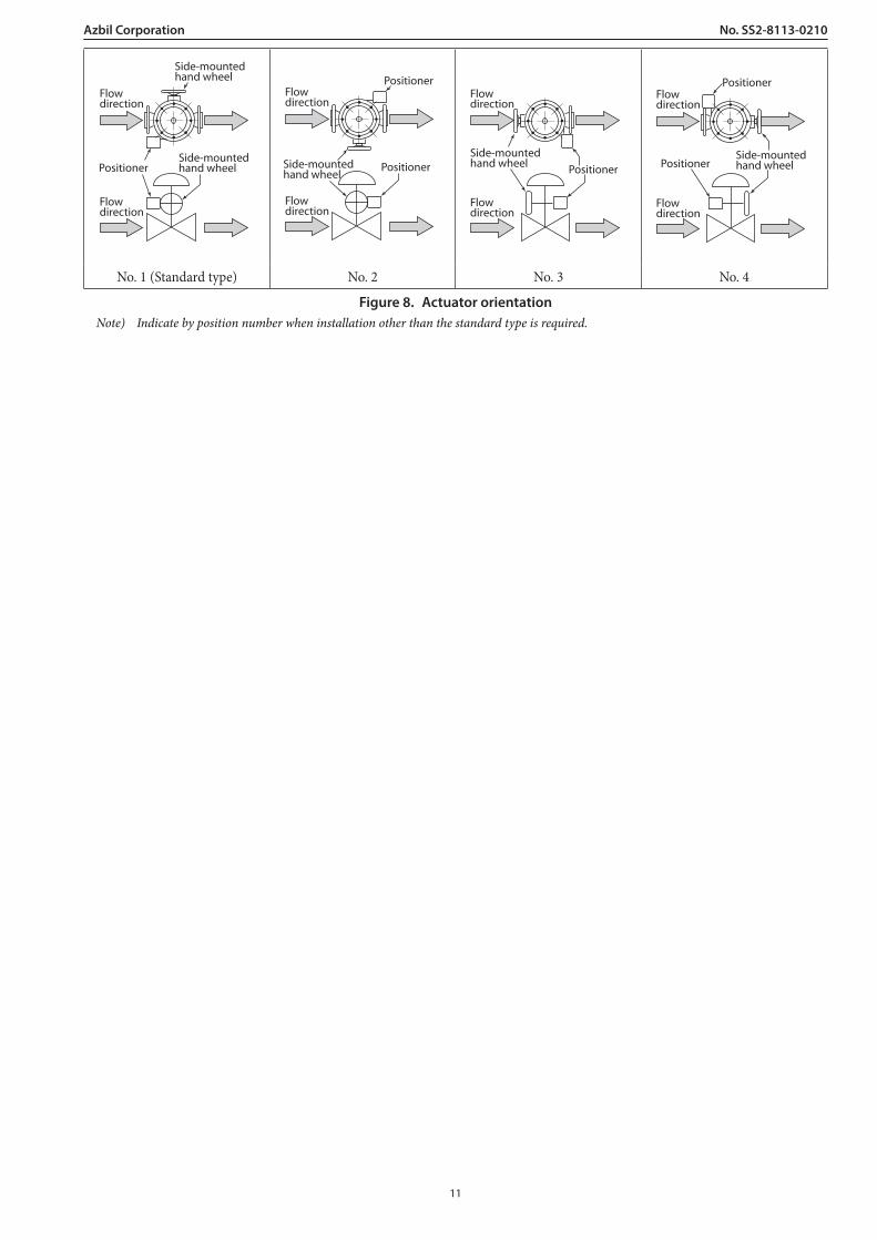
Actuator orientationRefer to Figure 8.
FinishBlue (Munsell 10B5/10) or silver, or other specified colors.
Table 1. Body/trim material combinations and operating temperature range (°C)
Body material
Trim material
JIS SCPH2 SCPH21 SCPH61 SCS11 SCS13A SCS14A SCS16A SCS19A
ASTM A216WCB A217WC6 A217C5 - A351CF8 A351CF8M A351CF3M A351CF3
JIS SUS440C -5 to +425 -5 to +425 -5 to +425 - - - - -
JIS SUS304 CoCr-A -5 to +425 -5 to +550 -5 to +566 - -196 to +550 - - -
JIS SUS304 CoCr-A face -5 to +425 -5 to +550 -5 to +566 - -196 to +550 - - -
JIS SUS316 CoCr-A -5 to +425 -5 to +550 -5 to +566 - -196 to +550 -196 to +550 - -
JIS SUS316 CoCr-A face -5 to +425 -5 to +550 -5 to +566 - -196 to +550 -196 to +550 - -
JIS SUS304L CoCr-A - - - - -196 to +550 - - -196 to +450
JIS SUS316L CoCr-A - - - - -196 to +450 -196 to +450 -196 to +450 -196 to +450
JIS SUS329J1 CoCr-A -50 to +550 - -196 to +550
Note) 1) “ ” shows standard combination of value body and trim materials. 2) SUS440C is recommended for values for cavitation/flashing service of water or for superheated service of water higher than 100°C. 3) When rated Cv value is 0.16 or lower CoCr-A faced valve plugs or SUS440C valve plugs are standard.
Table 2. Cv value travel
Plug type/ characteristics / Rated travel (mm) / Rated Cv 0.16 0.25 0.4 0.63 1.0 1.6 2.5 4.0
Contoured type
Metal seat
Equal percentage (%CC)14.3
Linear (LCC)
Inherent rangeability 20:1 30:1 50:1
Nominal size (inch)1/2
3/4, 1 Note) 1) “” denotes production ranges. 2) Please select model # HLS for values of rated Cv0.01, 0.04, 0.1
3
Azbil CorporationNo. SS2-8113-0210
100
50
20
10
5
20 20 40 60 80 100
Travel (%)
Cv
valu
e (%
)
100
80
60
40
20
00 20 40 60 80 100
Travel (%)
Cv
valu
e (%
)
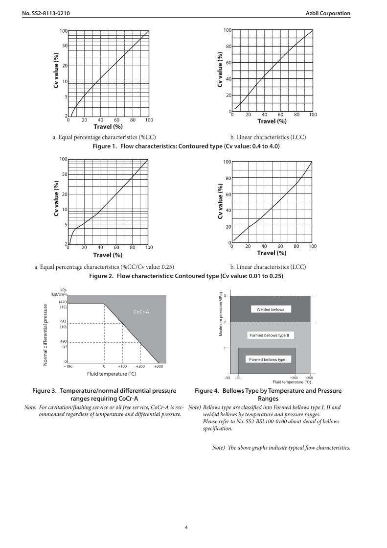
a. Equal percentage characteristics (%CC) b. Linear characteristics (LCC)Figure 1. Flow characteristics: Contoured type (Cv value: 0.4 to 4.0)
Cv
valu
e (%
)
Travel (%)
100
50
20
10
5
20 20 40 60 80 100 0 20 40 60 80 100
100
80
60
40
20
0
Travel (%)
Cv
valu
e (%
)
a. Equal percentage characteristics (%CC/Cv value: 0.25) b. Linear characteristics (LCC)Figure 2. Flow characteristics: Contoured type (Cv value: 0.01 to 0.25)
1470{15}
kPa{kgf/cm2}
981{10}
490{5}
0−196 0 +100 +200 +300
CoCr-A
Nor
mal
diff
eren
tial p
ress
ure
Fluid temperature (°C)
3
2
1
-50 -30 +300 +350
Max
imum
pre
ssur
e(M
Pa)
Welded bellows
Formed bellows type II
Formed bellows type I
Fluid temperature ( C)
Figure 3. Temperature/normal differential pressure ranges requiring CoCr-A
Figure 4. Bellows Type by Temperature and Pressure Ranges
Note: For cavitation/flashing service or oil free service, CoCr-A is rec-ommended regardless of temperature and differential pressure.
Note) Bellows type are classified into Formed bellows type I, II and welded bellows by temperature and pressure ranges. Please refer to No. SS2-BSL100-0100 about detail of bellows specification.
Note) The above graphs indicate typical flow characteristics.
4
No. SS2-8113-0210Azbil Corporation
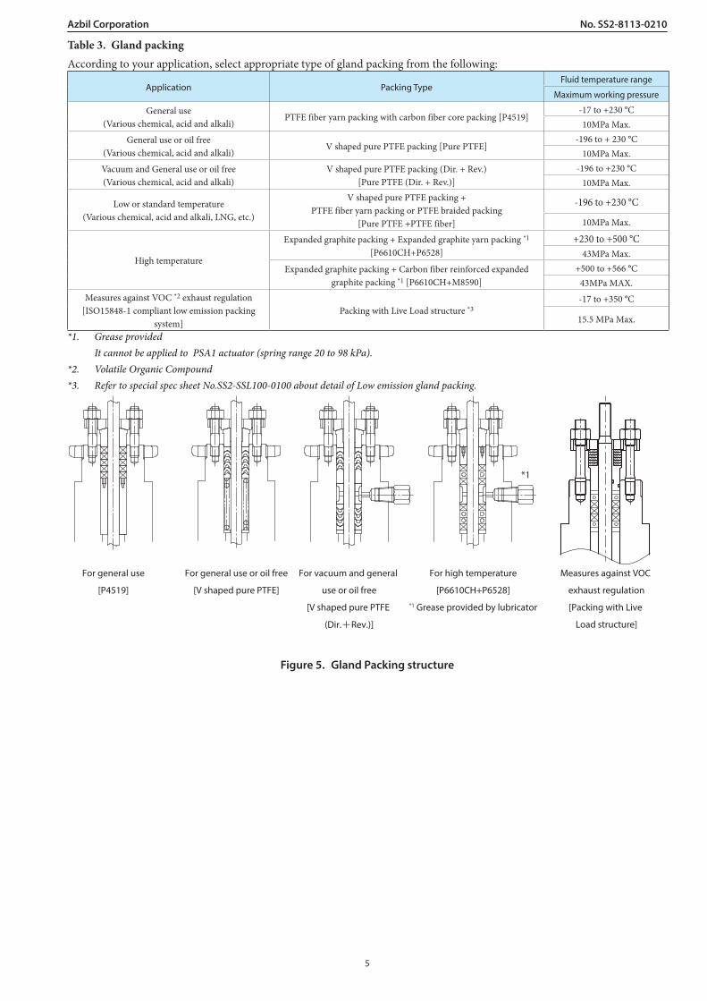
Table 3. Gland packingAccording to your application, select appropriate type of gland packing from the following:
Application Packing TypeFluid temperature range
Maximum working pressure
General use (Various chemical, acid and alkali)
PTFE fiber yarn packing with carbon fiber core packing [P4519]-17 to +230 °C10MPa Max.
General use or oil free(Various chemical, acid and alkali)
V shaped pure PTFE packing [Pure PTFE]-196 to + 230 °C
10MPa Max.Vacuum and General use or oil free(Various chemical, acid and alkali)
V shaped pure PTFE packing (Dir. + Rev.)[Pure PTFE (Dir. + Rev.)]
-196 to +230 °C10MPa Max.
Low or standard temperature(Various chemical, acid and alkali, LNG, etc.)
V shaped pure PTFE packing +PTFE fiber yarn packing or PTFE braided packing
[Pure PTFE +PTFE fiber]
-196 to +230 °C
10MPa Max.
High temperature
Expanded graphite packing + Expanded graphite yarn packing *1
[P6610CH+P6528]+230 to +500 °C
43MPa Max.Expanded graphite packing + Carbon fiber reinforced expanded
graphite packing *1 [P6610CH+M8590]+500 to +566 °C
43MPa MAX.Measures against VOC *2 exhaust regulation
[ISO15848-1 compliant low emission packing system]
Packing with Live Load structure *3-17 to +350 °C
15.5 MPa Max.
*1. Grease provided It cannot be applied to PSA1 actuator (spring range 20 to 98 kPa).*2. Volatile Organic Compound*3. Refer to special spec sheet No.SS2-SSL100-0100 about detail of Low emission gland packing.
For general use
[P4519]
For general use or oil free
[V shaped pure PTFE]
For vacuum and general
use or oil free
[V shaped pure PTFE
(Dir.+Rev.)]
For high temperature
[P6610CH+P6528]*1 Grease provided by lubricator
Measures against VOC
exhaust regulation
[Packing with Live
Load structure]
*1
Figure 5. Gland Packing structure
5

Azbil CorporationNo. SS2-8113-0210
Structural drawing of trim and body/trim material combinationsFollowing table shows typical body/trim material combinations.Please contact us about materials that are not listed in this table.
(3)
(4)(6)
(1)(2)
(5)Figure 6. Structural drawing of trim
Table 4. The valve body material is carbon steel (SCPH2/A216WCB).
(1) Valve plug(2) Seat ring
SUS440CSUS316 CoCr-A
SUS316 CoCr-A faceSUS304 CoCr-A
SUS304 CoCr-A face
General General Oil-free General Oil-free
(3)Valve stem SUS316
(4) Guide bushing, cage SUS440C SUS316 and solid CoCr-A
(5) Seat gasket WithoutSUS316
(PTFE coating)Without
SUS316 (PTFE coating)
(6) Bonnet gasket SUS316SUS316
(PTFE coating)SUS316
SUS316 (PTFE coating)
Table 5. The valve body material is stainless steel (SCS13A/A351CF8)
(1) Valve plug(2) Seat ring
SUS316 CoCr-ASUS316 CoCr-A face
SUS304 CoCr-ASUS304 CoCr-A face
General Oil-free General Oil-free
(3) Valve stem SUS316
(4) Guide bushing, cage SUS316 and solid CoCr-A
(5) Seat gasket Without SUS316(PTFE coating) Without SUS316(PTFE coating)
(6) Bonnet gasket SUS316 SUS316(PTFE coating) SUS316 SUS316(PTFE coating)
Table 6. The valve body material is stainless steel (SCS14A/A351CF8M)
(1) Valve plug(2) Seat ring
SUS316 CoCr-ASUS316 CoCr-A face
General Oil-free
(3) Valve stem SUS316
(4) Guide bushing, cage SUS316 and solid CoCr-A
(5) Seat gasket Without SUS316(PTFE coating)
(6) Bonnet gasket SUS316 SUS316(PTFE coating)
6

No. SS2-8113-0210Azbil Corporation
Allowable differential pressureContoured type metal seat (%CC LCC) : PTFE packing
Table 7. Air-to-close
Actuator Model
Supply pressure
kPa{kgf/cm2}
Spring range
kPa{kgf/cm2}
Posi-tioner
Differential pressure {by Cv value} kPa {kgf/cm2}
Below 0.25
0.4 0.63 1.0 1.6 2.5 4.0
PDA1D
140{1.4}
20 to 98{0.2 to 1.0}
3920{40.0} 3040
{31.0}3040{31.0}
1570{16.0}
1570{16.0}
981{10.0}
981{10.0}5490
{56.0}
160{1.6}
20 to 98{0.2 to 1.0}
3920{40.0}
3920{40.0}
3920{40.0}
3920{40.0}
3920{40.0}
3920{40.0}
3920{40.0}
9810{100}
9810{100}
9810{100}
8240{84.0}
8240{84.0}
5100{52.0}
5100{52.0}
390{4.0}
80 to 240{0.8 to 2.4} - - -
3920{40.0}
3920{40.0}
3920{40.0}
3920{40.0}
9810{100}
9810{100}
9810{100}
9810{100}
HA2D
140{1.4}
20 to 98{0.2 to 1.0}
3920{40.0}
3920{40.0}
3920{40.0} 3200
{32.6}3200{32.6}
1960{20.0}
1960{20.0}9810
{100}62.0
{6080}62.0
{6080}
160{1.6}
20 to 98{0.2 to 1.0} -
3920{40.0}
3920{40.0}
3920{40.0}
3920{40.0}
3920{40.0}
3920{40.0}
9810{100}
9810{100}
9810{100}
9810{100}
9810{100}
9810{100}
Table 8. Air-to-open
Actuator Model
Supply pressure
kPa{kgf/cm2}
Spring range
kPa{kgf/cm2}
Posi-tioner
Differential pressure {by Cv value} kPa {kgf/cm2}
Below 0.25
0.4 0.63 1.0 1.6 2.5 4.0
PSA1R
140{1.4}
20 to 98{0.2 to 1.0}
3920{40.0} 3040
{31.0}3040{31.0}
1570{16.0}
1570{16.0}
981{10.0}
981{10.0}5490
{56.0}
270{2.7}
80 to 240{0.8 to 2.4}
3920{40.0}
3920{40.0}
3920{40.0}
3920{40.0}
3920{40.0}
3920{40.0}
3920{40.0}
9810{100}
9810{100}
9810{100}
9810{100}
9810{100}
7060{72.0}
7060{72.0}
HA2R
140{1.4}
20 to 98{0.2 to 1.0}
3920{40.0}
3920{40.0}
3920{40.0} 3200
{32.6}3200{32.6}
1960{20.0}
1960{20.0}9810
{100}6080{62.0}
6080{62.0}
270{2.7}
80 to 240{0.8 to 2.4} -
3920{40.0}
3920{40.0}
3920{40.0}
3920{40.0}
3920{40.0}
3920{40.0}
9810{100}
9810{100}
9810{100}
9810{100}
9810{100}
9810{100}
Note) 1) : Positioner is necessary, : Can be operated either with or without positioner. 2) Take care not to cause the maximum permissible differential pressure to exceed the maximum operating pressure designated by
ANSI B 16. 34-1981 or JIS B2201-1984. 3) The upper figures denote the operating permissible differential pressure. The lower denote permissible differential pressure at full
closure.
7

Azbil CorporationNo. SS2-8113-0210
Contoured type metal seat (%CC LCC) : Graphite packing (+230 to +500 °C)
Table 9. Air-to-close
Actuator Model
Supply Pressure
kPa{kgf/cm2}
Spring range
kPa{kgf/cm2}
Posi-tioner
Differential pressure {by Cv value} kPa {kgf/cm2}
Below 0.25
0.4 0.63 1.0 1.6 2.5 4.0
HA2D390{4.0}
80 to 240{0.8 to 2.4}
3920*{40.0}
3920*{40.0}
3920*{40.0}
3920*{40.0}
3920*{40.0}
3920*{40.0}
3920*{40.0}
9810{100}
9810{100}
9810{100}
9810{100}
9810{100}
9810{100}
9810{100}
Table 10. Air-to-open
Actuator Model
Supply Pressure
kPa{kgf/cm2}
Spring range
kPa{kgf/cm2}
Posi-tioner
Differential pressure {by Cv value} kPa {kgf/cm2}
Below 0.25
0.4 0.63 1.0 1.6 2.5 4.0
HA2R270{2.8}
80 to 240{0.8 to 2.4}
3920*{40.0}
3920*{40.0}
3920*{40.0}
3920*{40.0}
3920*{40.0}
3920*{40.0}
3920*{40.0}
9810{100}
9810{100}
9810{100}
9810{100}
9810{100}
9810{100}
9810{100}
Note) 1) : Positioner is necessary. 2) Take care not to cause the maximum allowable differential pressure to exceed the maximum operating pressure designated by JIS B
2201-1984 or ANSI B 16.34-1981. 3) The upper figures denote the operating allowable differential pressure. The lower denote allowable differential pressure at full
closure.
Contoured type metal seat (%CC LCC) : Graphite packing “P6610+M8590” (+500 to +560 °C)
Table 11. Air-to-close
Actuator Model
Supply Pressure
kPa{kgf/cm2}
Spring range
kPa{kgf/cm2}
Posi-tioner
Differential pressure {by Cv value} kPa {kgf/cm2}
Below 0.25
0.4 0.63 1.0 1.6 2.5 4.0
HA2D390{4.0}
80 to 240{0.8 to 2.4}
3920*{40.0}
3920*{40.0}
3920*{40.0}
3920*{40.0}
3920*{40.0}
3920*{40.0}
3920*{40.0}
9810{100}
9810{100}
9810{100}
9810{100}
9810{100}
9810{100}
9810{100}
Table 12. Air-to-open
Actuator Model
Supply Pressure
kPa{kgf/cm2}
Spring range
kPa{kgf/cm2}
Posi-tioner
Differential pressure {by Cv value} kPa {kgf/cm2}
Below 0.25
0.4 0.63 1.0 1.6 2.5 4.0
HA2R270{2.8}
80 to 240{0.8 to 2.4}
3920*{40.0}
3920*{40.0}
3920*{40.0}
3920*{40.0}
3920*{40.0}
3920*{40.0}
3920*{40.0}
9810{100}
9810{100}
9810{100}
9810{100}
9810{100}
9810{100}
9260{94.4}
Note) 1) : Positioner is necessary. 2) Take care not to cause the maximum allowable differential pressure to exceed the maximum operating pressure
designated by JIS B 2201-1984 or ANSI B 16.34-1981. 3) The upper figures denote the operating allowable differential pressure. The lower denote allowable differential pres-
sure at full closure.
8

No. SS2-8113-0210Azbil Corporation
DIMENSIONSTable 13. Face-to-face dimensions (Unit: mm)
Nominal size
(inch)
A
JIS 10K FF,RFANSI 125FF
JPI 125FFANSI 150RFJPI 150RF *
JIS 16KRF
JIS20KRFJIS30KRF
ANSI300RFJPI300RF
*
JIS40KRFANSI600RF
JPI600RFSW,BW
*
ANSI150RJJPI150RJ
ANSI300RJJPI300RJ
ANSI 600RJJPI600RJ
JIS20K Tongue
and groove Male and
female
JIS30K Tongue
and groove Male and
female
ANSI 300LG
JP300LG
Screw- Type
1/2 184 190 194 206 - 206 206 198 208 203 1253/4 184 190 194 206 - 206 206 198 208 203 1251 184 193 197 210 197 210 210 198 212 206 125
1-1/2 222 231 235 251 235 248 251 236 248 244 -2 254 263 267 286 267 283 289 267 276 276 -
2-1/2 276 288 292 311 289 308 314 292 303 302 -3 298 313 317 337 311 333 340 317 326 327 -
Note) * : Face-to-face dimensions conform to following standards. -IEC 60534-3-1:2001 -JIS B 2005-3-1:2005
Table 14. External dimensions (Unit: mm)
Actuator Model
HBellowsbonnet φB B E
Plain bonnetExtension
bonnet Type 1
Extension bonnet Type 2
Integral cast type Welded type
PSA1D, R 416 566 726 941 576 218 230 40HA2D, R 450 600 760 975 608 267 281 40
Note) “H” dimensions are applicable when a hand wheel is not provided. When a top-mounted hand wheel actuator is used, add the dimensions of hand wheel specified on Specification Sheet (No.SS2-8213-0500).
B
H
E
A
B
H
E
A
a. For PSA actuator b. For HA actuatorFigure 7. Face-to-face and external dimensions
9
Azbil CorporationNo. SS2-8113-0210
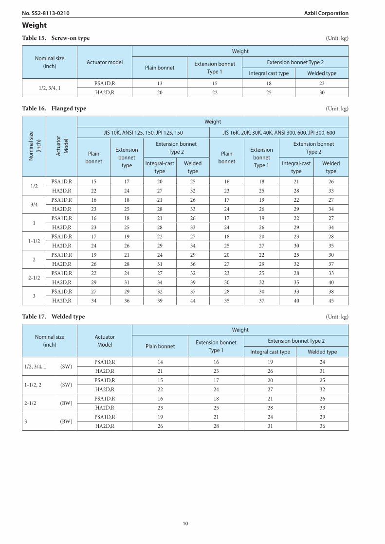
Weight
Table 15. Screw-on type (Unit: kg)
Nominal size (inch)
Actuator model
Weight
Plain bonnetExtension bonnet
Type 1
Extension bonnet Type 2
Integral cast type Welded type
1/2, 3/4, 1PSA1D,R 13 15 18 23HA2D,R 20 22 25 30
Table 16. Flanged type (Unit: kg)
Nom
inal
size
(inch
)
Actu
ator
Mod
el
Weight
JIS 10K, ANSI 125, 150, JPI 125, 150 JIS 16K, 20K, 30K, 40K, ANSI 300, 600, JPI 300, 600
Plain bonnet
Extension bonnet
type
Extension bonnet Type 2 Plain
bonnet
Extension bonnet Type 1
Extension bonnet Type 2
Integral-cast type
Welded type
Integral-cast type
Welded type
1/2PSA1D,R 15 17 20 25 16 18 21 26HA2D,R 22 24 27 32 23 25 28 33
3/4PSA1D,R 16 18 21 26 17 19 22 27HA2D,R 23 25 28 33 24 26 29 34
1PSA1D,R 16 18 21 26 17 19 22 27HA2D,R 23 25 28 33 24 26 29 34
1-1/2PSA1D,R 17 19 22 27 18 20 23 28HA2D,R 24 26 29 34 25 27 30 35
2PSA1D,R 19 21 24 29 20 22 25 30HA2D,R 26 28 31 36 27 29 32 37
2-1/2PSA1D,R 22 24 27 32 23 25 28 33HA2D,R 29 31 34 39 30 32 35 40
3PSA1D,R 27 29 32 37 28 30 33 38HA2D,R 34 36 39 44 35 37 40 45
Table 17. Welded type (Unit: kg)
Nominal size (inch)
ActuatorModel
Weight
Plain bonnetExtension bonnet
Type 1
Extension bonnet Type 2
Integral cast type Welded type
1/2, 3/4, 1 (SW)PSA1D,R 14 16 19 24HA2D,R 21 23 26 31
1-1/2, 2 (SW)PSA1D,R 15 17 20 25HA2D,R 22 24 27 32
2-1/2 (BW)PSA1D,R 16 18 21 26HA2D,R 23 25 28 33
3 (BW)PSA1D,R 19 21 24 29HA2D,R 26 28 31 36
10
No. SS2-8113-0210Azbil Corporation
Side-mountedhand wheel
Side-mountedhand wheel
Flowdirection
Flowdirection
Positioner Side-mountedhand wheel
Flowdirection
Flowdirection
Positioner
PositionerSide-mountedhand wheel
Flowdirection
Flowdirection
PositionerSide-mountedhand wheel
Flowdirection
Flowdirection
Positioner
Positioner
No. 1 (Standard type) No. 2 No. 3 No. 4
Figure 8. Actuator orientation Note) Indicate by position number when installation other than the standard type is required.
11

(16)
Please read “Terms and Conditions” from the following URL before ordering and use.https://www.azbil.com/products/factory/order.html
1-12-2 Kawana, FujisawaKanagawa 251-8522 Japan
https://www.azbil.com/
Specifications are subject to change without notice.
No part of this publication may be reproduced or duplicated without the prior written permission of Azbil Corporation.1212
Azbil CorporationNo. SS2-8113-0210
1st edition: Apr. 20018th edition: May 2019
Ordering informationWhen ordering, please specify;
1)2)3)4)5)6)7)
8)
Model Number: HLCNominal size × Cv requiredType and rating of end connectionsBody and trim materialType of bonnetValve and plug characteristicsType of actuator, necessity of manual hand wheel, air pressure to diaphragmValve action (direct or reverse)
9)10)
11)12)13)
14)15)
Accessories (pressure regulator with filter and etc.)Special requirement of oil/water free treatment, copper free treatment, etc.Name of flow mediumNormal flow and maximum required flowPressure of flow medium, upstream and downstream pressure at maximum and minimum, required flowTemperature and specific gravity of flow medium Viscosity of flow medium, inclusive or exclusive of slurry