Embed Size (px)
Citation preview
SMART RING
A Single Phase Air Insulated Ring Main Unit and Compact Switchgear
Installation and Operating Instructions
OP2016V008
SMART RING 12 KV RING MAIN UNIT
SMART RING
A Single Phase Air Insulated Ring Main Unit and Compact Switchgear
Installation and Operating Instructions
OP2016V008
CONTENTS
1. General Description
1.1 Layout
1.2 Dimensional Drawings
2. Transport and Handling
3. Technical Data
4. Installation
4.1 Front Covers
4.2 Cable Compartment
4.3 Cable Connection
4.4 Current Transformers for Relay Protection
4.5 Relay Protection
5. Additional Equipment
5.1 Auxiliary Switches
5.2 Motor Drive
5.3 Remote Closing (RC),
5.4 Fault Indicators, type ProTrol
5.5 Extension with more bays at site
5.6 Change a line feeder into a transformer bay and vice versa
5.7 Top entry box for low voltage cables
5.8 Metering Cubicle
5.9 Electronic phase comparator
6. Environmental Certification
7. Operating Instructions
SMART RING
A Single Phase Air Insulated Ring Main Unit and Compact Switchgear
Installation and Operating Instructions
OP2016V008
1. GENERAL DESCRIPTION
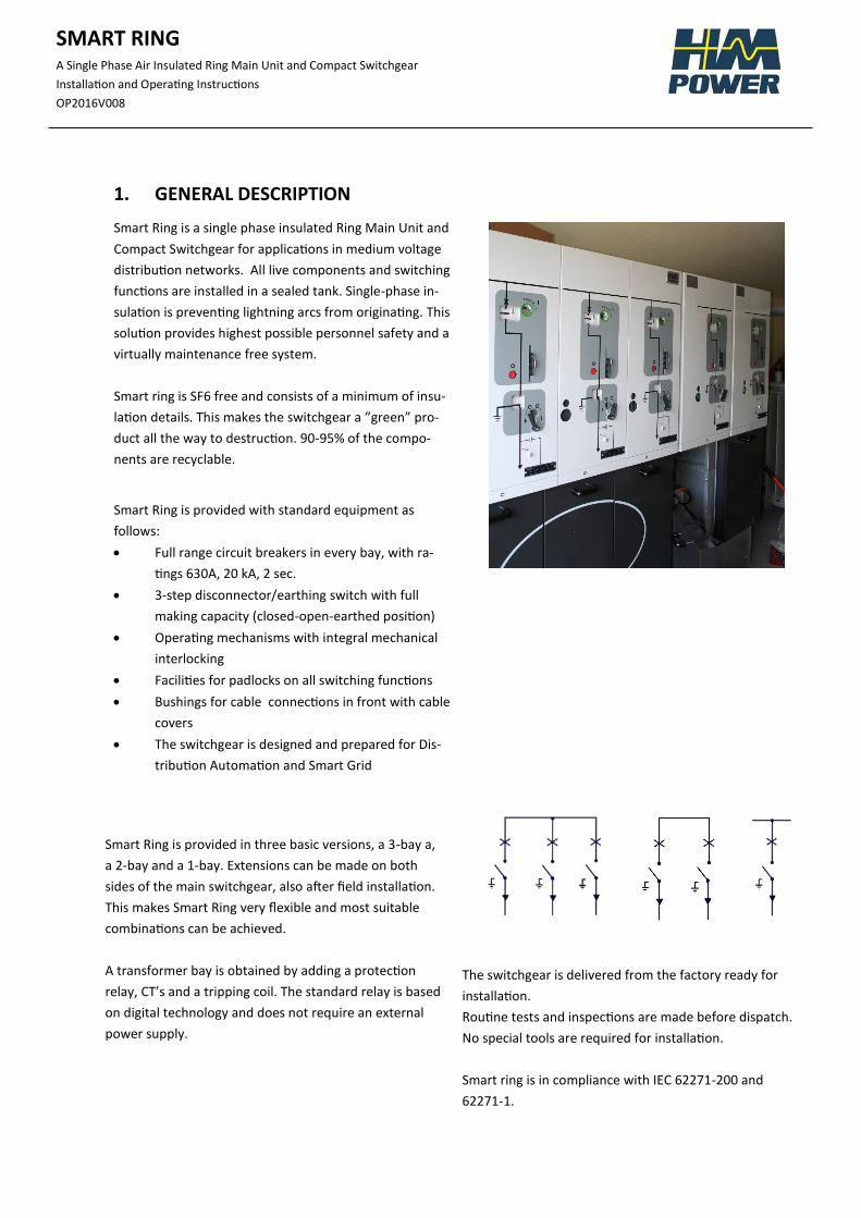
Smart Ring is a single phase insulated Ring Main Unit and
Compact Switchgear for applications in medium voltage
distribution networks. All live components and switching
functions are installed in a sealed tank. Single-phase in-
sulation is preventing lightning arcs from originating. This
solution provides highest possible personnel safety and a
virtually maintenance free system.
Smart ring is SF6 free and consists of a minimum of insu-
lation details. This makes the switchgear a ”green” pro-
duct all the way to destruction. 90-95% of the compo-
nents are recyclable.
Smart Ring is provided with standard equipment as
follows:
Full range circuit breakers in every bay, with ra-
tings 630A, 20 kA, 2 sec.
3-step disconnector/earthing switch with full
making capacity (closed-open-earthed position)
Operating mechanisms with integral mechanical
interlocking
Facilities for padlocks on all switching functions
Bushings for cable connections in front with cable
covers
The switchgear is designed and prepared for Dis-
tribution Automation and Smart Grid
Smart Ring is provided in three basic versions, a 3-bay a,
a 2-bay and a 1-bay. Extensions can be made on both
sides of the main switchgear, also after field installation.
This makes Smart Ring very flexible and most suitable
combinations can be achieved.
A transformer bay is obtained by adding a protection
relay, CT’s and a tripping coil. The standard relay is based
on digital technology and does not require an external
power supply.
The switchgear is delivered from the factory ready for
installation.
Routine tests and inspections are made before dispatch.
No special tools are required for installation.
Smart ring is in compliance with IEC 62271-200 and
62271-1.
SMART RING
A Single Phase Air Insulated Ring Main Unit and Compact Switchgear
Installation and Operating Instructions
OP2016V008
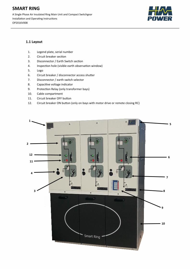
1.1 Layout
1
2
3
4
5
6
7
8
9
10
11
12
1. Legend plate, serial number
2. Circuit breaker section
3. Disconnector / Earth Switch section
4. Inspection hole (visible earth observation window)
5. Logo
6. Circuit breaker / disconnector access shutter
7. Disconnector / earth switch selector
8. Capacitive voltage indicator
9. Protection Relay (only transformer bays)
10. Cable compartment
11. Circuit breaker OFF button
12. Circuit breaker ON button (only on bays with motor drive or remote closing RC)
SMART RING
A Single Phase Air Insulated Ring Main Unit and Compact Switchgear
Installation and Operating Instructions
OP2016V008
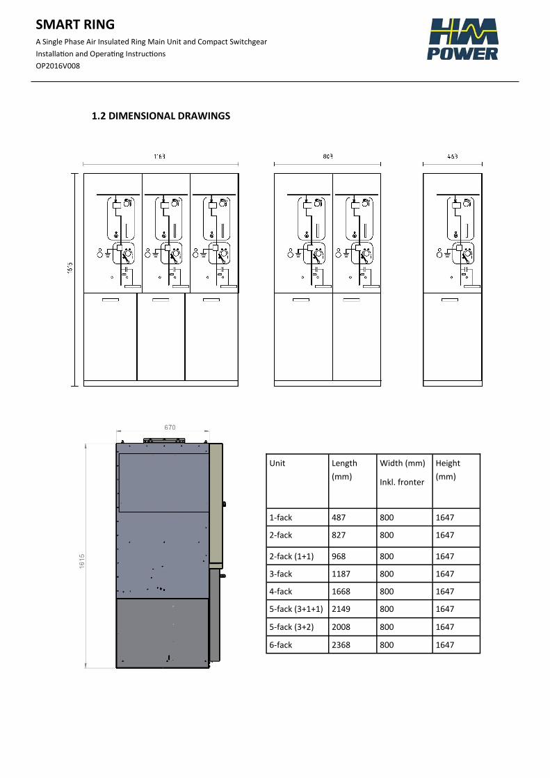
1.2 DIMENSIONAL DRAWINGS
Unit Length
(mm)
Width (mm)
Inkl. fronter
Height
(mm)
1-fack 487 800 1647
2-fack 827 800 1647
2-fack (1+1) 968 800 1647
3-fack 1187 800 1647
4-fack 1668 800 1647
5-fack (3+1+1) 2149 800 1647
5-fack (3+2) 2008 800 1647
6-fack 2368 800 1647
SMART RING
A Single Phase Air Insulated Ring Main Unit and Compact Switchgear
Installation and Operating Instructions
OP2016V008
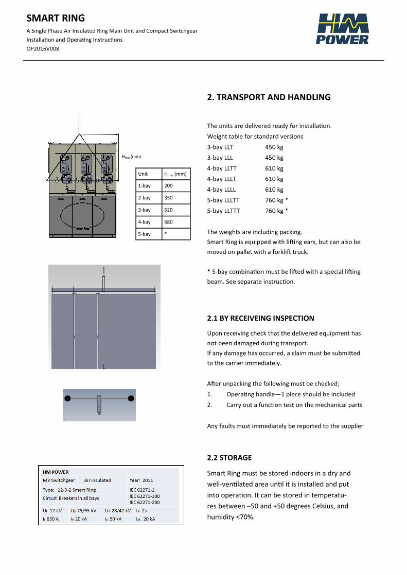
2. TRANSPORT AND HANDLING
The units are delivered ready for installation.
Weight table for standard versions
3-bay LLT 450 kg
3-bay LLL 450 kg
4-bay LLTT 610 kg
4-bay LLLT 610 kg
4-bay LLLL 610 kg
5-bay LLLTT 760 kg *
5-bay LLTTT 760 kg *
The weights are including packing.
Smart Ring is equipped with lifting ears, but can also be
moved on pallet with a forklift truck.
* 5-bay combination must be lifted with a special lifting
beam. See separate instruction.
2.1 BY RECEIVEING INSPECTION
Upon receiving check that the delivered equipment has
not been damaged during transport.
If any damage has occurred, a claim must be submitted
to the carrier immediately.
After unpacking the following must be checked;
1. Operating handle—1 piece should be included
2. Carry out a function test on the mechanical parts
Any faults must immediately be reported to the supplier
2.2 STORAGE
Smart Ring must be stored indoors in a dry and
well-ventilated area until it is installed and put
into operation. It can be stored in temperatu-
res between –50 and +50 degrees Celsius, and
humidity <70%.
Unit Hmin (mm)
1-bay 200
2-bay 350
3-bay 520
4-bay 680
5-bay *
Hmin (mm)
SMART RING
A Single Phase Air Insulated Ring Main Unit and Compact Switchgear
Installation and Operating Instructions
OP2016V008
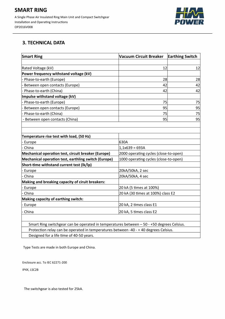
3. TECHNICAL DATA
Smart Ring Vacuum Circuit Breaker Earthing Switch
Rated Voltage (kV) 12 12
Power frequency withstand voltage (kV)
- Phase-to-earth (Europe) 28 28
- Between open contacts (Europe) 42 42
- Phase-to-earth (China) 42 42
Impulse withstand voltage (kV)
- Phase-to-earth (Europe) 75 75
- Between open contacts (Europe) 95 95
- Phase-to-earth (China) 75 75
- Between open contacts (China) 95 95
Temperature rise test with load, (50 Hz)
- Europe 630A
- China 1,1x639 = 693A
Mechanical operation test, circuit breaker (Europe) 2000 operating cycles (close-to-open)
Mechanical operation test, earthling switch (Europe) 1000 operating cycles (close-to-open)
Short-time withstand current test (lk/lp)
- Europe 20kA/50kA, 2 sec
- China 20kA/50kA, 4 sec
Making and breaking capacity of ciruit breakers:
- Europe 20 kA (5 times at 100%)
- China 20 kA (30 times at 100%) class E2
Making capacity of earthing switch:
- Europe 20 kA, 2 times class E1
- China 20 kA, 5 times class E2
Smart Ring switchgear can be operated in temperatures between – 50 - +50 degrees Celsius.
Protection relay can be operated in temperatures between -40 - + 40 degrees Celsius. Designed for a life time of 40-50 years.
Enclosure acc. To IEC 62271-200
IP4X, LSC2B
Type Tests are made in both Europe and China.
The switchgear is also tested for 25kA.
SMART RING
A Single Phase Air Insulated Ring Main Unit and Compact Switchgear
Installation and Operating Instructions
OP2016V008
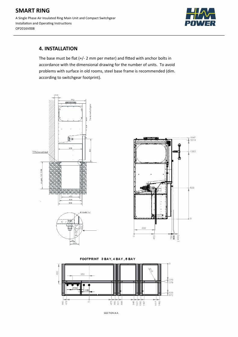
4. INSTALLATION
The base must be flat (+/- 2 mm per meter) and fitted with anchor bolts in
accordance with the dimensional drawing for the number of units. To avoid
problems with surface in old rooms, steel base frame is recommended (dim.
according to switchgear footprint).
SMART RING
A Single Phase Air Insulated Ring Main Unit and Compact Switchgear
Installation and Operating Instructions
OP2016V008
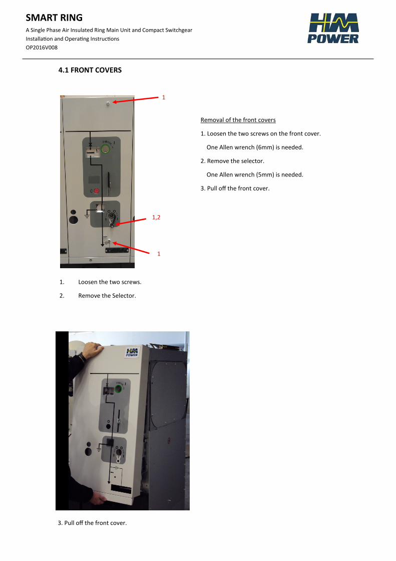
4.1 FRONT COVERS
Removal of the front covers
1. Loosen the two screws on the front cover.
One Allen wrench (6mm) is needed.
2. Remove the selector.
One Allen wrench (5mm) is needed.
3. Pull off the front cover.
1. Loosen the two screws.
2. Remove the Selector.
3. Pull off the front cover.
1
1
1,2
SMART RING
A Single Phase Air Insulated Ring Main Unit and Compact Switchgear
Installation and Operating Instructions
OP2016V008
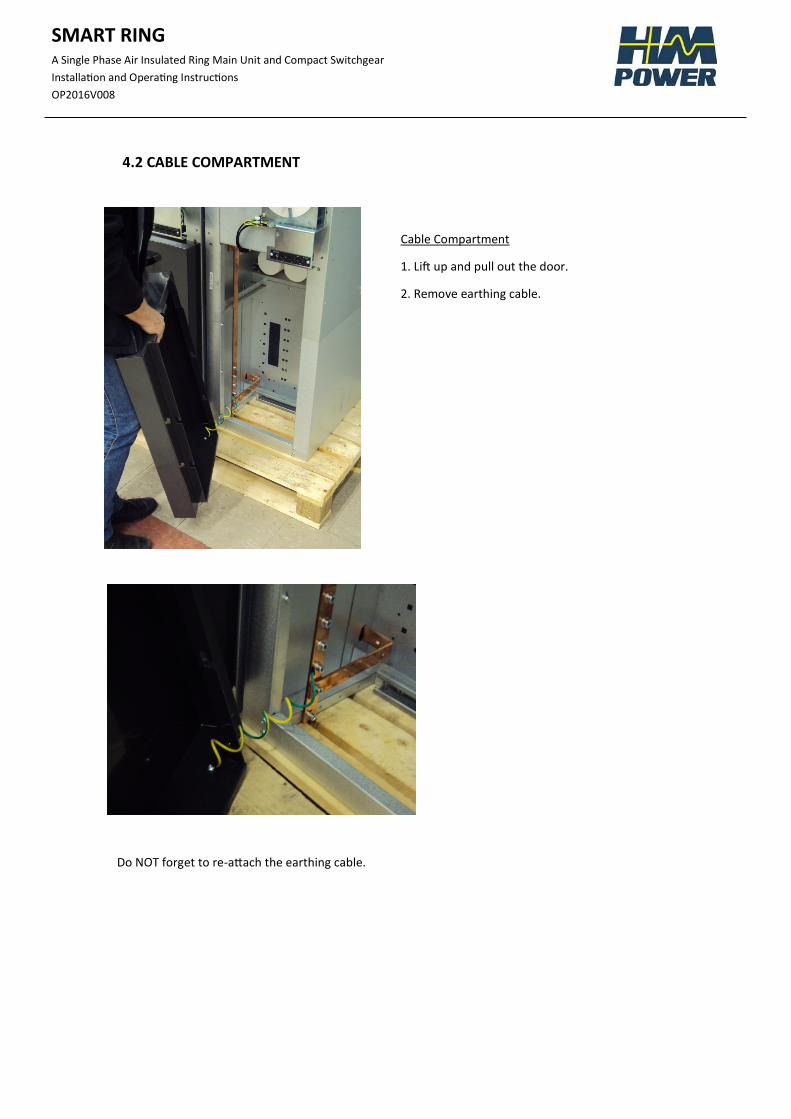
4.2 CABLE COMPARTMENT
Cable Compartment
1. Lift up and pull out the door.
2. Remove earthing cable.
Do NOT forget to re-attach the earthing cable.
SMART RING
A Single Phase Air Insulated Ring Main Unit and Compact Switchgear
Installation and Operating Instructions
OP2016V008
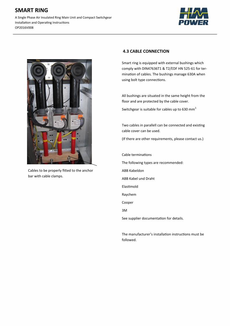
4.3 CABLE CONNECTION
Smart ring is equipped with external bushings which
comply with DIN47636T1 & T2/EDF HN 525-61 for ter-
mination of cables. The bushings manage 630A when
using bolt type connections.
All bushings are situated in the same height from the
floor and are protected by the cable cover.
Switchgear is suitable for cables up to 630 mm2.
Two cables in parallell can be connected and existing
cable cover can be used.
(If there are other requirements, please contact us.)
Cable terminations
The following types are recommended:
ABB Kabeldon
ABB Kabel und Draht
Elastimold
Raychem
Cooper
3M
See supplier documentation for details.
The manufacturer’s installation instructions must be
followed.
Cables to be properly fitted to the anchor
bar with cable clamps.
SMART RING
A Single Phase Air Insulated Ring Main Unit and Compact Switchgear
Installation and Operating Instructions
OP2016V008
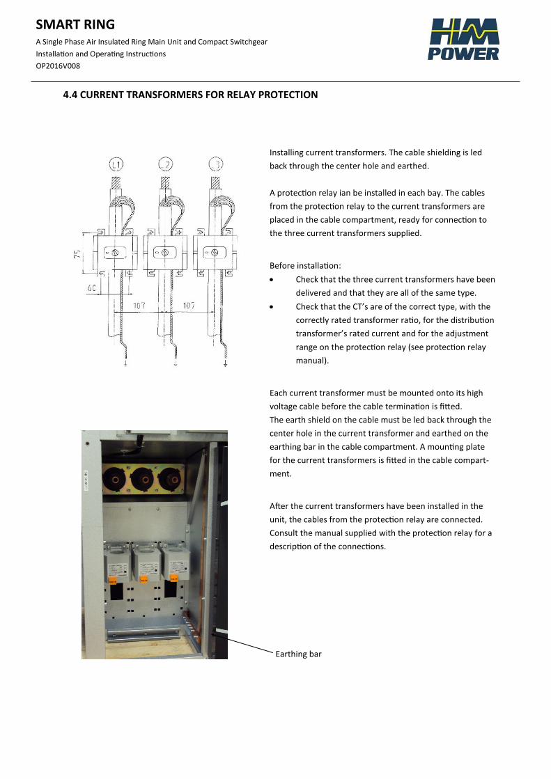
4.4 CURRENT TRANSFORMERS FOR RELAY PROTECTION
Installing current transformers. The cable shielding is led
back through the center hole and earthed.
A protection relay ian be installed in each bay. The cables
from the protection relay to the current transformers are
placed in the cable compartment, ready for connection to
the three current transformers supplied.
Before installation:
Check that the three current transformers have been
delivered and that they are all of the same type.
Check that the CT’s are of the correct type, with the
correctly rated transformer ratio, for the distribution
transformer’s rated current and for the adjustment
range on the protection relay (see protection relay
manual).
Each current transformer must be mounted onto its high
voltage cable before the cable termination is fitted.
The earth shield on the cable must be led back through the
center hole in the current transformer and earthed on the
earthing bar in the cable compartment. A mounting plate
for the current transformers is fitted in the cable compart-
ment.
After the current transformers have been installed in the
unit, the cables from the protection relay are connected.
Consult the manual supplied with the protection relay for a
description of the connections.
Earthing bar
SMART RING
A Single Phase Air Insulated Ring Main Unit and Compact Switchgear
Installation and Operating Instructions
OP2016V008
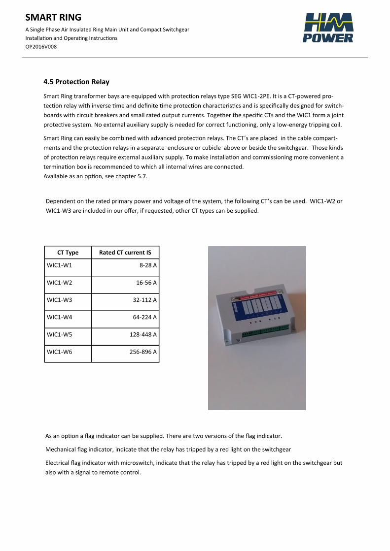
4.5 Protection Relay
Smart Ring transformer bays are equipped with protection relays type SEG WIC1-2PE. It is a CT-powered pro-
tection relay with inverse time and definite time protection characteristics and is specifically designed for switch-
boards with circuit breakers and small rated output currents. Together the specific CTs and the WIC1 form a joint
protective system. No external auxiliary supply is needed for correct functioning, only a low-energy tripping coil.
Smart Ring can easily be combined with advanced protection relays. The CT’s are placed in the cable compart-
ments and the protection relays in a separate enclosure or cubicle above or beside the switchgear. Those kinds
of protection relays require external auxiliary supply. To make installation and commissioning more convenient a
termination box is recommended to which all internal wires are connected.
Available as an option, see chapter 5.7.
CT Type Rated CT current IS
WIC1-W1 8-28 A
WIC1-W2 16-56 A
WIC1-W3 32-112 A
WIC1-W4 64-224 A
WIC1-W5 128-448 A
WIC1-W6 256-896 A
Dependent on the rated primary power and voltage of the system, the following CT’s can be used. WIC1-W2 or
WIC1-W3 are included in our offer, if requested, other CT types can be supplied.
As an option a flag indicator can be supplied. There are two versions of the flag indicator.
Mechanical flag indicator, indicate that the relay has tripped by a red light on the switchgear
Electrical flag indicator with microswitch, indicate that the relay has tripped by a red light on the switchgear but
also with a signal to remote control.
SMART RING
A Single Phase Air Insulated Ring Main Unit and Compact Switchgear
Installation and Operating Instructions
OP2016V008
5. ADDITIONAL EQUIPMENT
5.1 Auxiliary Switches
Microswitches can be supplied to indicate circuit breaker position and position of disconnector/earthing
switch.
Maximum number of microswitches that can be delivered:
Indicate circuit breaker position 3no+3nc
Indicate earth switch postition 2no+2nc
Indicate disconnector position 3no+3nc
Indicate springs charged
Indicate springs NOT charged
If other indicators are needed, contact us for more information.
Microswitches delivered on different types of bays:
Line bay
No microswitches.
Transformer bay
Circuit breaker 2no+2nc
Remote control (RC)
Springs charged.
Motor Drive
Circuit breaker 2no+2nc
Earth Switch 2no+2nc
Disconnector 2no+2nc
Springs charged
SMART RING
A Single Phase Air Insulated Ring Main Unit and Compact Switchgear
Installation and Operating Instructions
OP2016V008
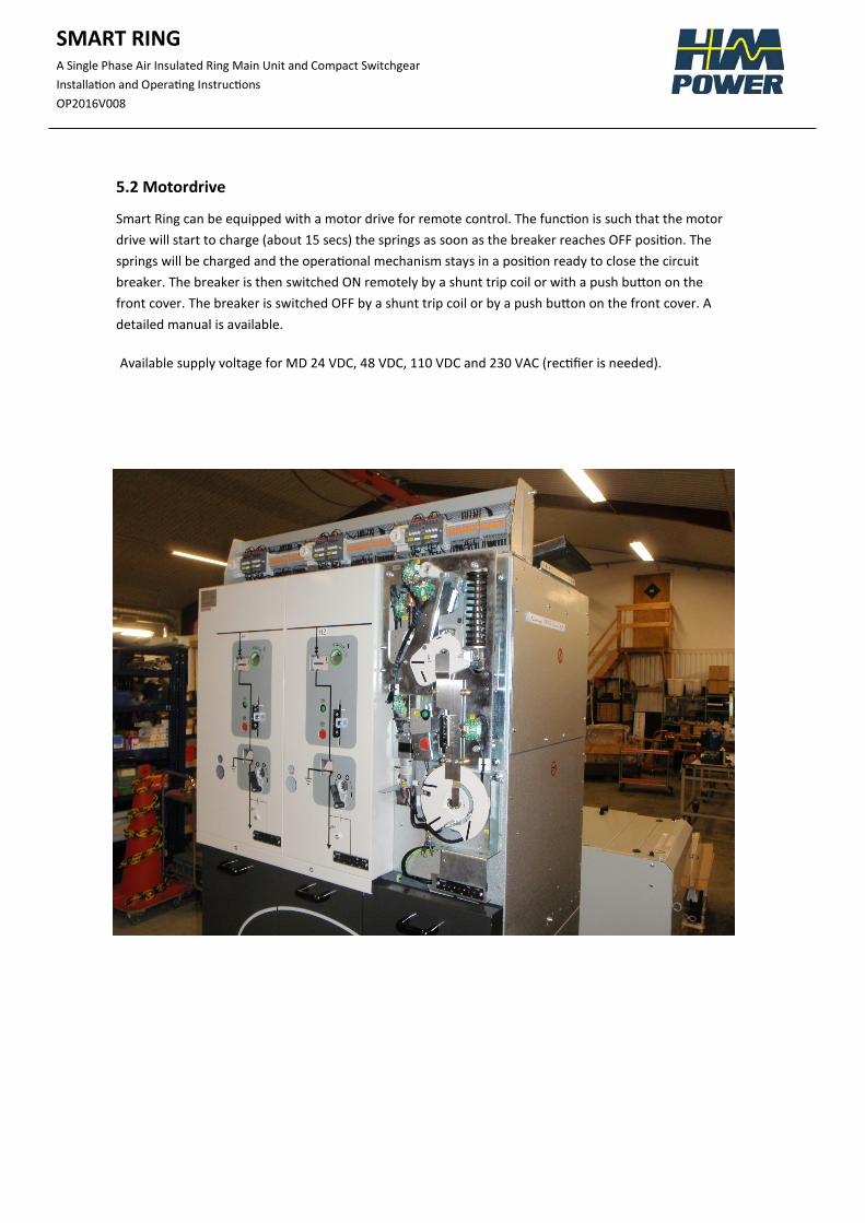
5.2 Motordrive
Smart Ring can be equipped with a motor drive for remote control. The function is such that the motor
drive will start to charge (about 15 secs) the springs as soon as the breaker reaches OFF position. The
springs will be charged and the operational mechanism stays in a position ready to close the circuit
breaker. The breaker is then switched ON remotely by a shunt trip coil or with a push button on the
front cover. The breaker is switched OFF by a shunt trip coil or by a push button on the front cover. A
detailed manual is available.
Available supply voltage for MD 24 VDC, 48 VDC, 110 VDC and 230 VAC (rectifier is needed).
SMART RING
A Single Phase Air Insulated Ring Main Unit and Compact Switchgear
Installation and Operating Instructions
OP2016V008
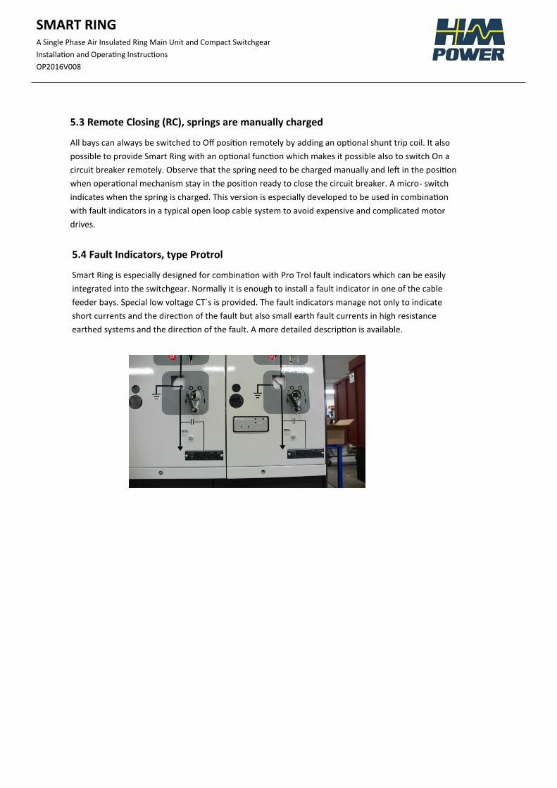
5.4 Fault Indicators, type Protrol
Smart Ring is especially designed for combination with Pro Trol fault indicators which can be easily
integrated into the switchgear. Normally it is enough to install a fault indicator in one of the cable
feeder bays. Special low voltage CT´s is provided. The fault indicators manage not only to indicate
short currents and the direction of the fault but also small earth fault currents in high resistance
earthed systems and the direction of the fault. A more detailed description is available.
5.3 Remote Closing (RC), springs are manually charged
All bays can always be switched to Off position remotely by adding an optional shunt trip coil. It also
possible to provide Smart Ring with an optional function which makes it possible also to switch On a
circuit breaker remotely. Observe that the spring need to be charged manually and left in the position
when operational mechanism stay in the position ready to close the circuit breaker. A micro- switch
indicates when the spring is charged. This version is especially developed to be used in combination
with fault indicators in a typical open loop cable system to avoid expensive and complicated motor
drives.
SMART RING
A Single Phase Air Insulated Ring Main Unit and Compact Switchgear
Installation and Operating Instructions
OP2016V008
5.6 Change a line feeder into a transformer bay and vice versa
A transformer bay kit is provided for changing a line feeder into a transformer
bay. The kit consists of CT’s, a protection relay and tripping coil. By adding them
to a line feeder a transformer bay is obtained.
By removing CT’s, protection relay and tripping coil from a transformer bay it is
changed into a line feeder.
5.5 Extension with more bays at site
It is possible to extend the Smart Ring at site in both left and right direction.
Busbar must be deenergized. Mandate to do the work has only persons with
written authorization from HM Power. Please make contact with us for further
information.
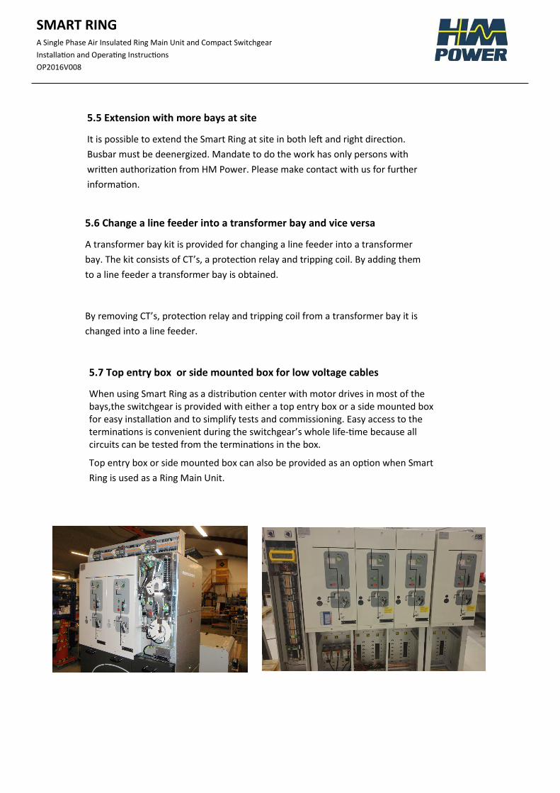
5.7 Top entry box or side mounted box for low voltage cables
When using Smart Ring as a distribution center with motor drives in most of the bays,the switchgear is provided with either a top entry box or a side mounted box for easy installation and to simplify tests and commissioning. Easy access to the terminations is convenient during the switchgear’s whole life-time because all circuits can be tested from the terminations in the box.
Top entry box or side mounted box can also be provided as an option when Smart
Ring is used as a Ring Main Unit.
SMART RING
A Single Phase Air Insulated Ring Main Unit and Compact Switchgear
Installation and Operating Instructions
OP2016V008
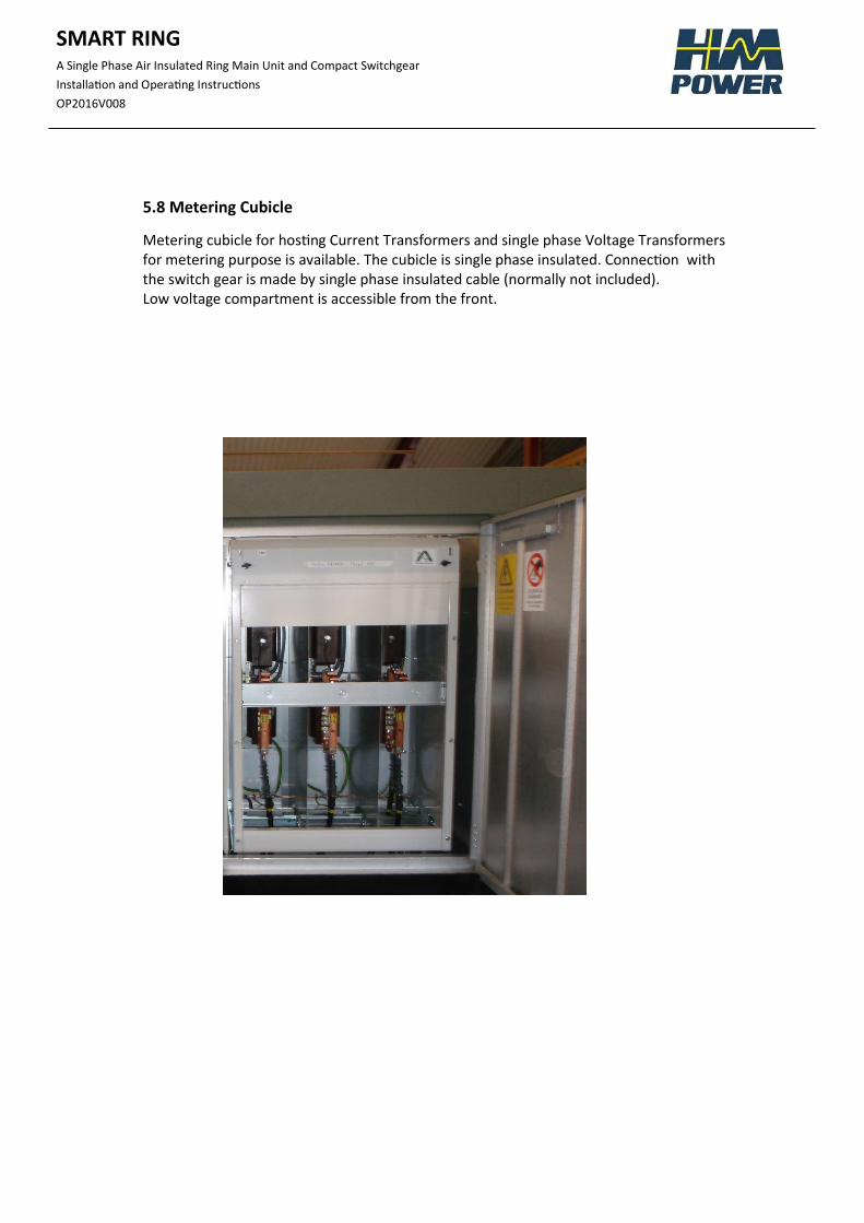
5.8 Metering Cubicle
Metering cubicle for hosting Current Transformers and single phase Voltage Transformers for metering purpose is available. The cubicle is single phase insulated. Connection with the switch gear is made by single phase insulated cable (normally not included). Low voltage compartment is accessible from the front.
SMART RING
A Single Phase Air Insulated Ring Main Unit and Compact Switchgear
Installation and Operating Instructions
OP2016V008
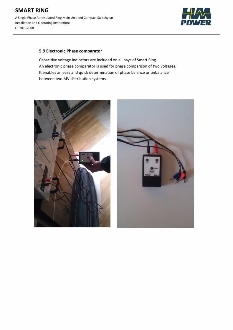
5.9 Electronic Phase comparator
Capacitive voltage indicators are included on all bays of Smart Ring.
An electronic phase comparator is used for phase comparison of two voltages.
It enables an easy and quick determination of phase balance or unbalance
between two MV distribution systems.
SMART RING
A Single Phase Air Insulated Ring Main Unit and Compact Switchgear
Installation and Operating Instructions
OP2016V008
Life Expectancy of Product
The product is developed in compliance with the requirements of standard IEC 62271.
Smart Ring is gas free and designed for an expected life time of 40-50 years.
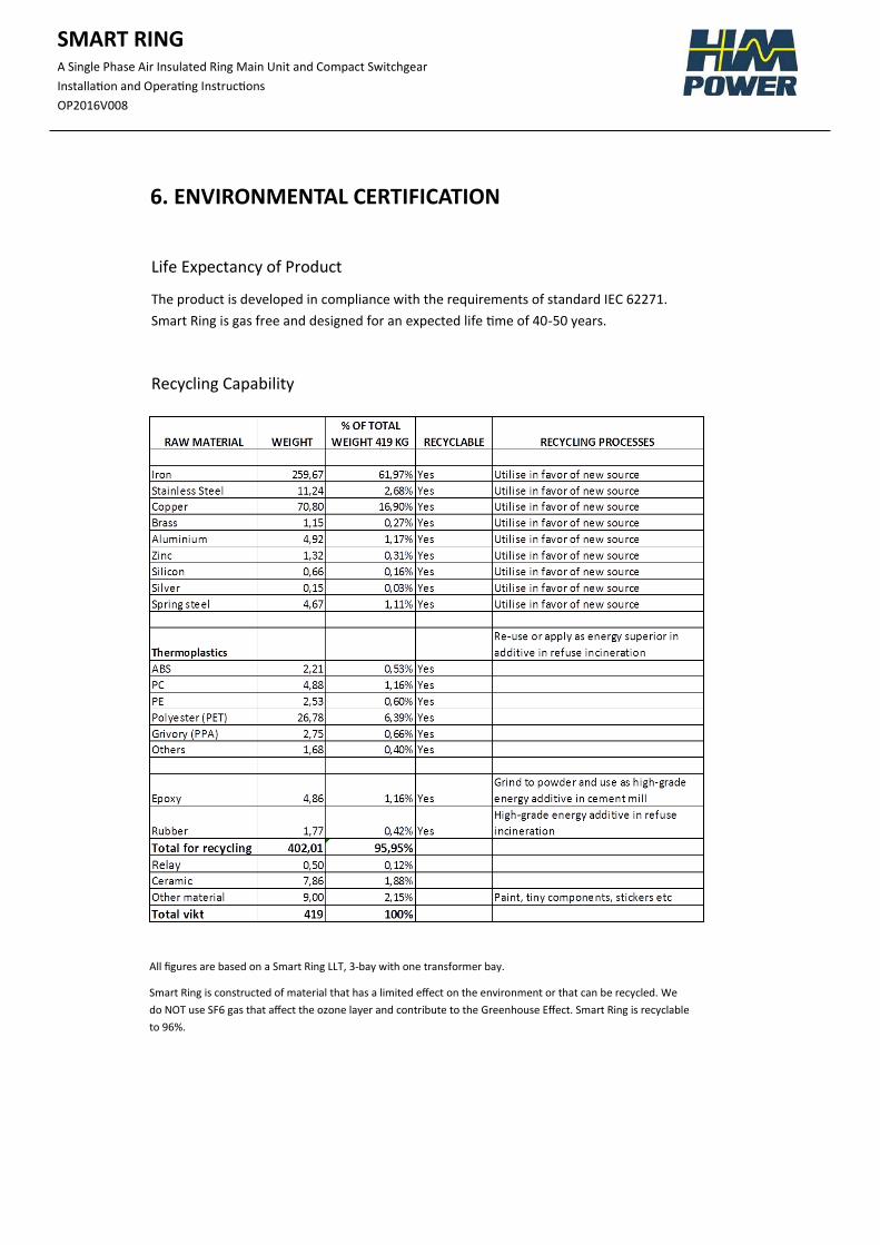
Recycling Capability
All figures are based on a Smart Ring LLT, 3-bay with one transformer bay.
Smart Ring is constructed of material that has a limited effect on the environment or that can be recycled. We
do NOT use SF6 gas that affect the ozone layer and contribute to the Greenhouse Effect. Smart Ring is recyclable
to 96%.
6. ENVIRONMENTAL CERTIFICATION
SMART RING
A Single Phase Air Insulated Ring Main Unit and Compact Switchgear
Installation and Operating Instructions
OP2016V008
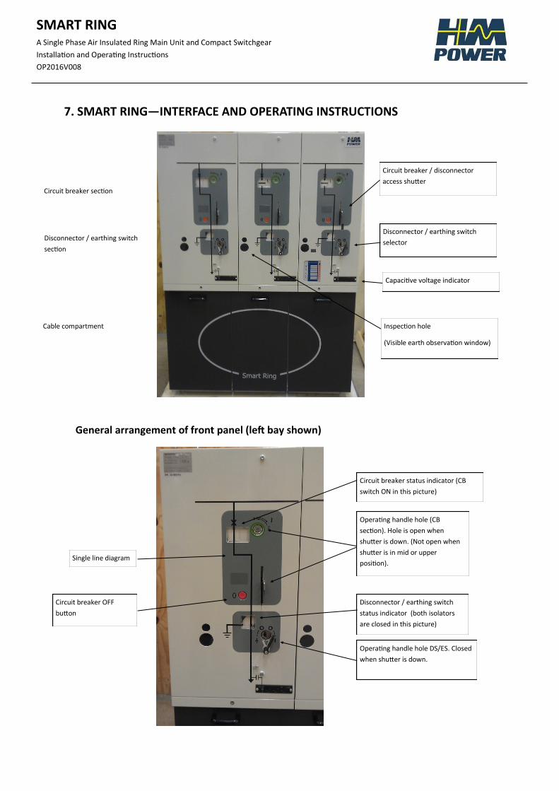
7. SMART RING—INTERFACE AND OPERATING INSTRUCTIONS
General arrangement of front panel (left bay shown)
Circuit breaker section
Disconnector / earthing switch
section
Cable compartment
Circuit breaker / disconnector
access shutter
Disconnector / earthing switch
selector
Capacitive voltage indicator
Inspection hole
(Visible earth observation window)
Circuit breaker status indicator (CB
switch ON in this picture)
Operating handle hole (CB
section). Hole is open when
shutter is down. (Not open when
shutter is in mid or upper
position).
Disconnector / earthing switch
status indicator (both isolators
are closed in this picture)
Operating handle hole DS/ES. Closed
when shutter is down.
Circuit breaker OFF
button
Single line diagram
SMART RING
A Single Phase Air Insulated Ring Main Unit and Compact Switchgear
Installation and Operating Instructions
OP2016V008
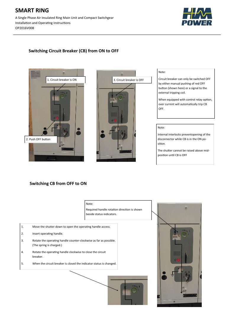
Switching Circuit Breaker (CB) from ON to OFF
Switching CB from OFF to ON
1. Circuit breaker is ON
2. Push OFF button
3. Circuit breaker is OFF
Note:
Circuit breaker can only be switched OFF
by either manual pushing of red OFF
button (shown here) or a signal to the
external tripping coil.
When equipped with control relay option,
over current will automatically trip CB
OFF.
Note:
Internal interlocks preventopening of the
disconnector while CB is in the ON po-
sition.
The shutter cannot be raised above mid-
position until CB is OFF
1. Move the shutter down to open the operating handle access.
2. Insert operating handle.
3. Rotate the operating handle counter-clockwise as far as possible.
(The spring is charged.)
4. Rotate the operating handle clockwise to close the circuit
breaker.
5. When the circuit breaker is closed the indicator status is changed.
Note:
Required handle rotation direction is shown
beside status indicators.
SMART RING
A Single Phase Air Insulated Ring Main Unit and Compact Switchgear
Installation and Operating Instructions
OP2016V008
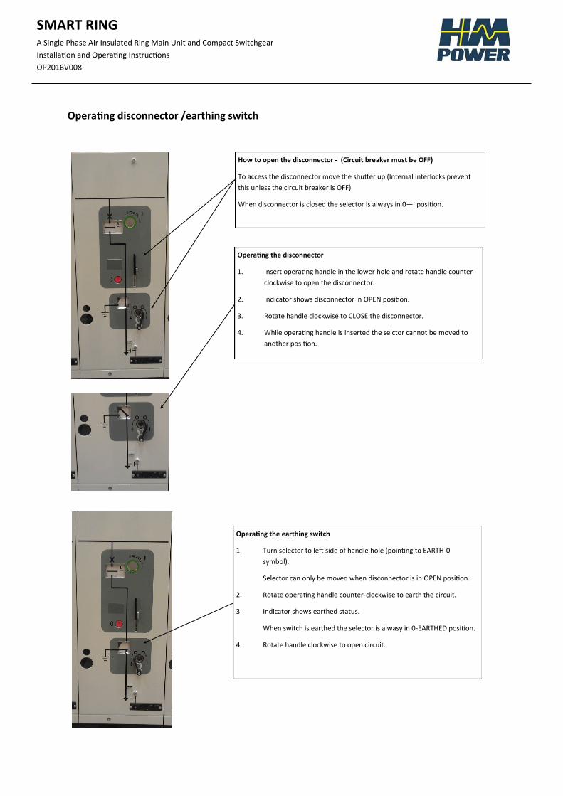
Operating disconnector /earthing switch
How to open the disconnector - (Circuit breaker must be OFF)
To access the disconnector move the shutter up (Internal interlocks prevent
this unless the circuit breaker is OFF)
When disconnector is closed the selector is always in 0—I position.
Operating the disconnector
1. Insert operating handle in the lower hole and rotate handle counter-
clockwise to open the disconnector.
2. Indicator shows disconnector in OPEN position.
3. Rotate handle clockwise to CLOSE the disconnector.
4. While operating handle is inserted the selctor cannot be moved to
another position.
Operating the earthing switch
1. Turn selector to left side of handle hole (pointing to EARTH-0
symbol).
Selector can only be moved when disconnector is in OPEN position.
2. Rotate operating handle counter-clockwise to earth the circuit.
3. Indicator shows earthed status.
When switch is earthed the selector is alwasy in 0-EARTHED position.
4. Rotate handle clockwise to open circuit.
SMART RING
A Single Phase Air Insulated Ring Main Unit and Compact Switchgear
Installation and Operating Instructions
OP2016V008
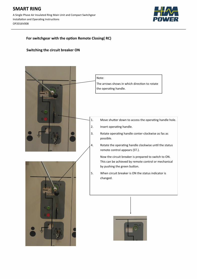
For switchgear with the option Remote Closing( RC)
Switching the circuit breaker ON
Note:
The arrows shows in which direction to rotate
the operating handle.
1. Move shutter down to access the operating handle hole.
2. Insert operating handle.
3. Rotate operating handle conter-clockwise as fas as
possible.
4. Rotate the operating handle clockwise until the status
remote control appears (ST.).
Now the circuit breaker is prepared to switch to ON.
This can be achieved by remote control or mechanical
by pushing the green button.
5. When circuit breaker is ON the status indicator is
changed.
SMART RING
A Single Phase Air Insulated Ring Main Unit and Compact Switchgear
Installation and Operating Instructions
OP2016V008
4. MOTOR DRIVE WITH PRE-CHARGED SPRINGS
4.1 Function
As soon as auxiliary power is connected the motor starts to charge the springs och stops in the position
Springs Charged (ST).
SWITCHING CB ON by pushing the green button manually (alt by remote control) which gives a solenoid
an impulse and the circuit breaker is switched on.
SWITCH CB OFF by pushing the red OFF-button or a signal to the external tripping coil by remote control or
a protection relay.
When the circuit breaker is in OFF position, the motor starts to charge the springs again and stops in the
position Springs Charged (ST), takes 17 seconds.
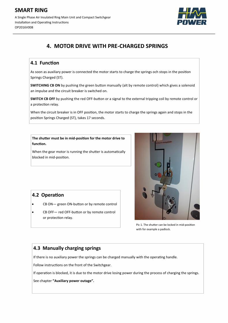
The shutter must be in mid-position for the motor drive to
function.
When the gear motor is running the shutter is automatically
blocked in mid-position.
Pic 1. The shutter can be locked in mid-position
with for example a padlock.
4.2 Operation
CB ON— green ON-button or by remote control
CB OFF— red OFF-button or by remote control
or protection relay.
4.3 Manually charging springs
If there is no auxiliary power the springs can be charged manually with the operating handle.
Follow instructions on the front of the Switchgear.
If operation is blocked, it is due to the motor drive losing power during the process of charging the springs.
See chapter ”Auxiliary power outage”.
SMART RING
A Single Phase Air Insulated Ring Main Unit and Compact Switchgear
Installation and Operating Instructions
OP2016V008
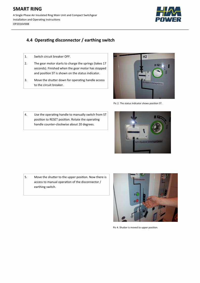
1. Switch circuit breaker OFF.
2. The gear motor starts to charge the springs (takes 17
seconds). Finished when the gear motor has stopped
and position ST is shown on the status indicator.
3. Move the shutter down for operating handle access
to the circuit breaker.
Pic 2. The status indicator shows position ST.
Pic 4. Shutter is moved to upper position.
4.4 Operating disconnector / earthing switch
4. Use the operating handle to manually switch from ST
position to RESET position. Rotate the operating
handle counter-clockwise about 20 degrees.
5. Move the shutter to the upper position. Now there is
access to manual operation of the disconnector /
earthing switch.
SMART RING
A Single Phase Air Insulated Ring Main Unit and Compact Switchgear
Installation and Operating Instructions
OP2016V008
4.5 Auxiliary power outage
What happens with the motor drive if there is an auxiliary power outage, for example if a fuse blows or a
MCB trips?
The gear motor stops
What happens when the auxiliary power returns?
The gear motor starts again and stops when the springs are charged (position ST).
Do not worry if it seems that the gear motor runs for a long time. Depending on where it was in its
spring charging cycle when the power outage occured, it may have to redo the whole cycle again.
4.6 Force the circuit breaker to ON position
What happens if the auxiliary power does not return and I still want to manually operate the switchgear?
WARNING! If you want to force the circuit breaker to ON position you must consider
the operating consequences carefully before the switch to ON is made.
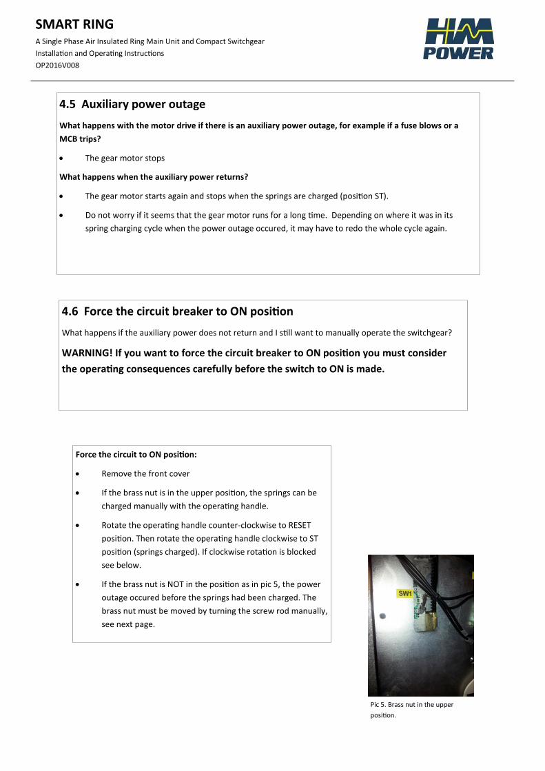
Force the circuit to ON position:
Remove the front cover
If the brass nut is in the upper position, the springs can be
charged manually with the operating handle.
Rotate the operating handle counter-clockwise to RESET
position. Then rotate the operating handle clockwise to ST
position (springs charged). If clockwise rotation is blocked
see below.
If the brass nut is NOT in the position as in pic 5, the power
outage occured before the springs had been charged. The
brass nut must be moved by turning the screw rod manually,
see next page.
Pic 5. Brass nut in the upper
position.
SMART RING
A Single Phase Air Insulated Ring Main Unit and Compact Switchgear
Installation and Operating Instructions
OP2016V008
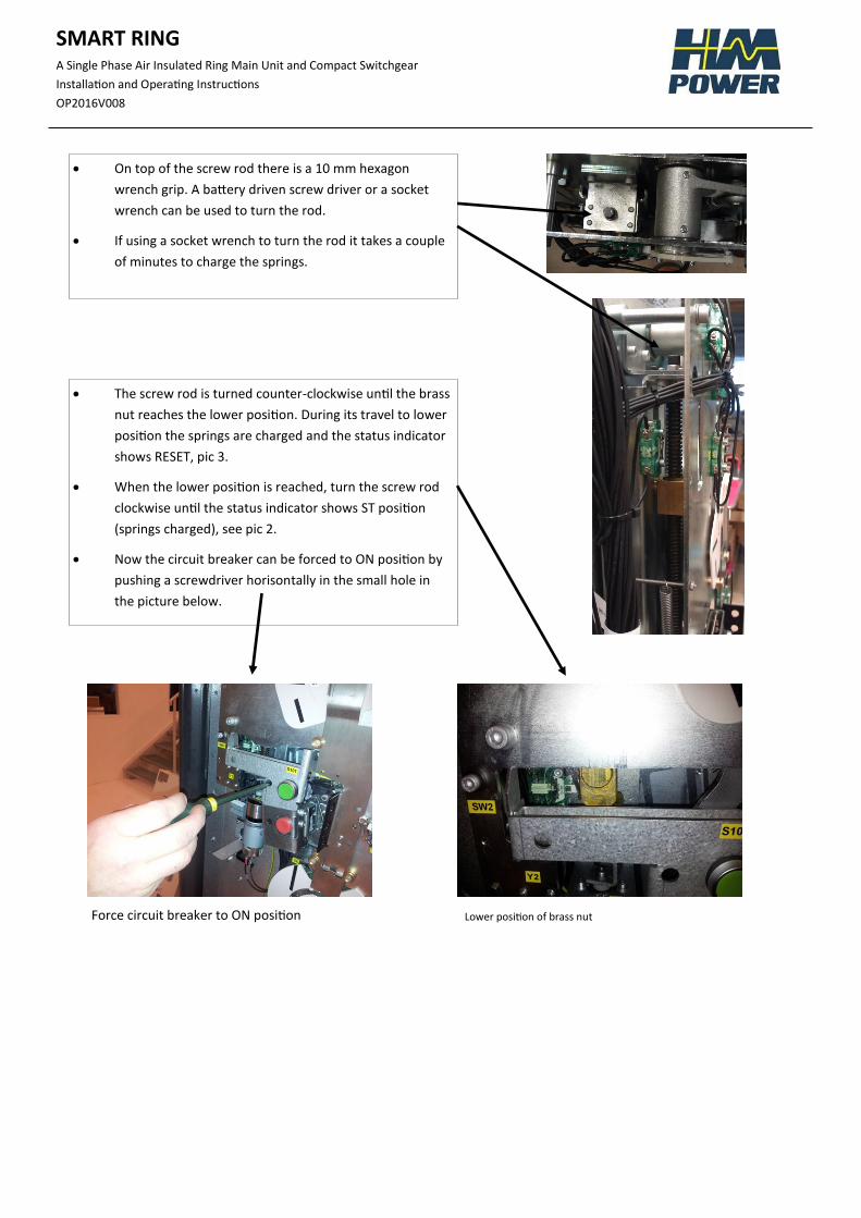
On top of the screw rod there is a 10 mm hexagon
wrench grip. A battery driven screw driver or a socket
wrench can be used to turn the rod.
If using a socket wrench to turn the rod it takes a couple
of minutes to charge the springs.
The screw rod is turned counter-clockwise until the brass
nut reaches the lower position. During its travel to lower
position the springs are charged and the status indicator
shows RESET, pic 3.
When the lower position is reached, turn the screw rod
clockwise until the status indicator shows ST position
(springs charged), see pic 2.
Now the circuit breaker can be forced to ON position by
pushing a screwdriver horisontally in the small hole in
the picture below.
Lower position of brass nut Force circuit breaker to ON position