Embed Size (px)
Citation preview
Smart Self-Controlled Vehicle for Motion Image Tracking
First Prize
Smart Self-Controlled Vehicle for Motion Image Tracking
Institution: Department of Information Engineering, I-Shou University
Participants: Chang-Che Wu, Shih-Hsin Chou, Chia-Hung Chao, Chia-Wei Hsu
Instructor: Dr. Ming-Haw Jing
Design IntroductionAutomobile electronics pose high requirements for safety, and the number of automobiles on the road is huge. According to Global Automotive Components, there were 760 million automobiles in 2004 and 850 million in 2005. General Motors projects that by 2020, there will be 1.1 billion automobiles worldwide. Data from IC Insights shows that until 2010, automobiles with on-board electronics will account for 40% of these vehicles. Therefore, there is a huge potential for growth in the automobile electronics market, which can generate substantial profit for automobile vendors as well as provide an opportunity for rapid growth of Taiwan’s high-tech vendors. In these circumstances, auto electronics will become the highlight of Taiwan’s research and development.
Our project uses image processing technology to provide identification and implement self-controlled auto guidance. For example, if the driver is not familiar with backing an auto into the garage, he/she can start the electronic automated guide setting for automated guidance, speed control, identification, etc.
In October 2007, Toyota’s latest Lexus models, the LS 460 and LS 460L, were marketed in U.S. These models are equipped with Toyota’s latest Advanced Parking Guidance System. The system uses a backward camera and a sonar sensor to detect the vehicle’s surroundings. If the driver presses a button and turns on the brakes to control the auto’s speed next to a parking space, the system automatically hands over the power steering to finish parking.
Similarly, the automatic guided vehicle (AGV), which is most commonly used in automated factory systems, can move forward, stop, and turn following the commands and routes of the program, and can be linked to a material handling system. A type of fully automated material handling equipment, an AGV can load goods automatically at a fixed location and move to another location for unloading. The
125
Nios II Embedded Processor Design Contest—Outstanding Designs 2007
basic function of the AGV is to walk automatically along a fixed track. Although this technology has been used in factories, it cannot be used in a complex environment because its route must be planned in advance and the track must be drawn on the ground.
Unlike the AGV, our project uses images to identify a mark, the position of which can be altered according to the application environment. Compared with traditional AGVs, our design has wider application. Additionally, this design can search for a specific mark, automatically analyze the existing image information, lock in on the object, and control the automobile. Besides assisting people with parking and backing into a garage, the system can be used for airplanes and any other power vehicle. This project implements a machine vision algorithm based on a hardware acceleration module, and uses the efficient, multi-core embedded Nios® II processor to implement the self-controlled automobile guidance platform. In the future, the design can implement many applications such as auto security, including anti-bumping, driveway deviation alarms, driveway retaining (i.e., guiding the driver to the original path), rear obstacle alarm, pedestrian monitoring, distance monitoring (i.e., keeping the driver some distance away from the auto ahead), night viewing, automatic headlight adjustment, transportation/speed-limit sign identification, blind spot monitoring, etc.
Using two embedded Nios II soft-core processors, this design integrates complex peripheral circuits and memory modules into an auto control platform through the easily designed, highly integrated Avalon® bus. With the high-performance Nios II processor, the design can easily implement real-time image processing and high-speed automated control products.
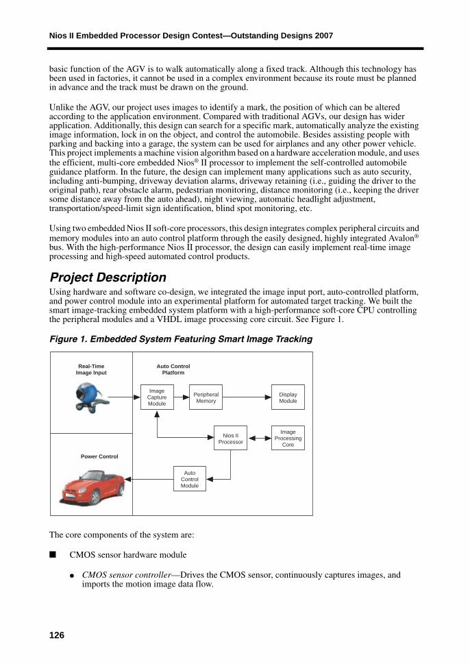
Project DescriptionUsing hardware and software co-design, we integrated the image input port, auto-controlled platform, and power control module into an experimental platform for automated target tracking. We built the smart image-tracking embedded system platform with a high-performance soft-core CPU controlling the peripheral modules and a VHDL image processing core circuit. See Figure 1.
Figure 1. Embedded System Featuring Smart Image Tracking
The core components of the system are:
■ CMOS sensor hardware module
● CMOS sensor controller—Drives the CMOS sensor, continuously captures images, and imports the motion image data flow.
Real-TimeImage Input
Auto ControlPlatform
ImageCaptureModule
PeripheralMemory
DisplayModule
AutoControlModule
Nios IIProcessor
ImageProcessing
Core
Power Control
126
Smart Self-Controlled Vehicle for Motion Image Tracking
● Data simplification—Compresses the image data (GB and GR) captured by the CMOS sensor, reducing the computing workload and analysis time.
● SDRAM controller—With six FIFO controllers, it allots SDRAM resources to two CMOS sensor controllers and VGA controllers (three for writing and three for reading).
■ VGA hardware modules
● VGA controller—Uses its components to display images on VGA directly in real time.
● XY histogram—Marks the target’s position with XY coordinates and makes a histogram of the X and Y axes for real-time images.
■ Power control—With a second soft-core CPU executing instructions from outside, the CPU drives the wheel’s control circuits with four groups of programmable I/Os (PIOs), controlling whether the auto goes forward/backward or turns left or right.
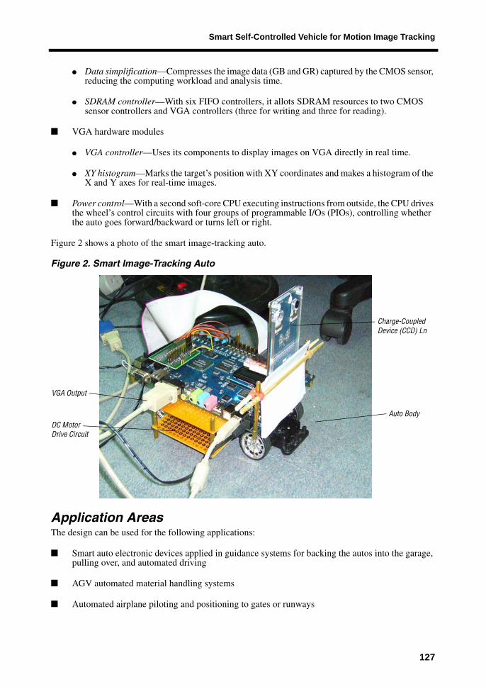
Figure 2 shows a photo of the smart image-tracking auto.
Figure 2. Smart Image-Tracking Auto
Application AreasThe design can be used for the following applications:
■ Smart auto electronic devices applied in guidance systems for backing the autos into the garage, pulling over, and automated driving
■ AGV automated material handling systems
■ Automated airplane piloting and positioning to gates or runways
VGA Output
DC Motor Auto Body
Drive Circuit
Charge-CoupledDevice (CCD) Ln
127
Nios II Embedded Processor Design Contest—Outstanding Designs 2007
■ Automated image and visualization control interfaces, such as input interfaces used for toy autos or boats, or control commands (e.g., video game handsets)
■ Automated guidance for assistance equipment such as wheelchairs and electric autos
Target UsersOur design targets the following users:
■ Automobile electronics equipment manufacturers
■ AGV automated guidance auto-controlled system vendors
■ Airplane automated piloting and control system manufacturers
■ Home entertainment product manufacturers
■ Assistance equipment manufacturers
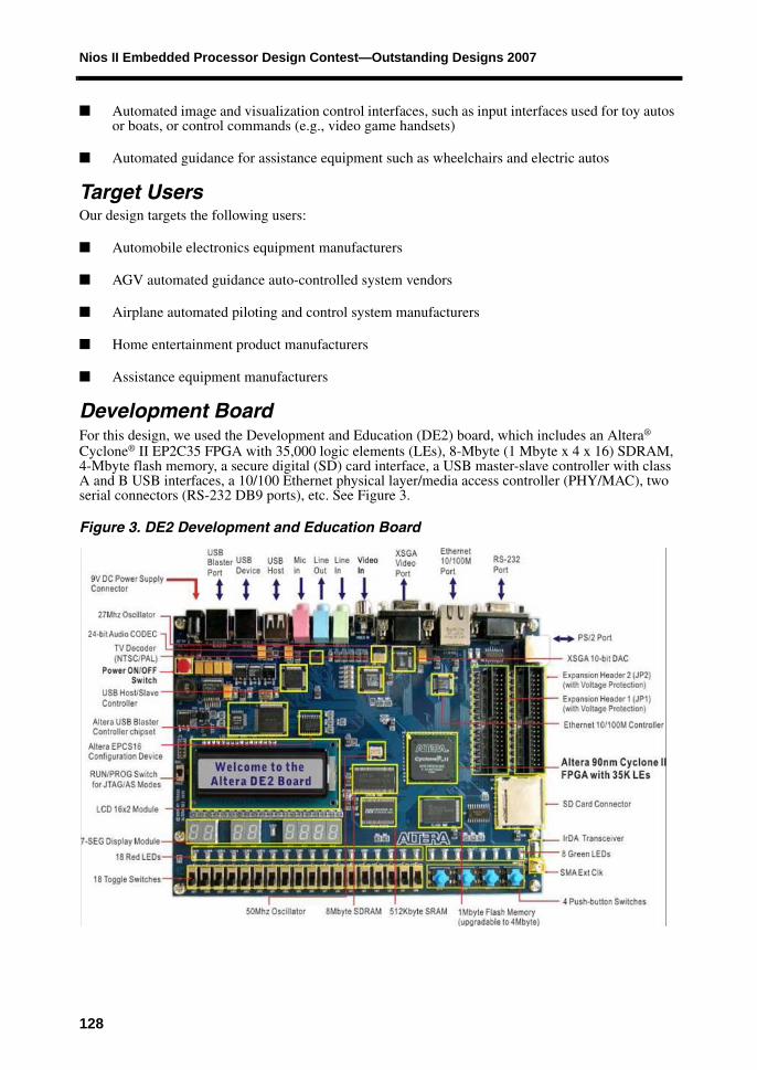
Development BoardFor this design, we used the Development and Education (DE2) board, which includes an Altera® Cyclone® II EP2C35 FPGA with 35,000 logic elements (LEs), 8-Mbyte (1 Mbyte x 4 x 16) SDRAM, 4-Mbyte flash memory, a secure digital (SD) card interface, a USB master-slave controller with class A and B USB interfaces, a 10/100 Ethernet physical layer/media access controller (PHY/MAC), two serial connectors (RS-232 DB9 ports), etc. See Figure 3.
Figure 3. DE2 Development and Education Board
128
Smart Self-Controlled Vehicle for Motion Image Tracking
Function DescriptionWe used the Quartus® II software version 7.1 to design the Data Compress and XY Histogram cores of the smart vehicle guidance system. We created the cores using VHDL and Verilog HDL. Our design has the following functionality:
■ Captures images with a CMOS sensor, reduces the number of images using data simplification, and displays them on-screen in real time via the VGA controller.
■ Analyzes the reduced image data and generates statistics on the X and Y axis for analysis.
■ Builds the whole system’s infrastructure with SOPC Builder, complete hardware and software co-design, and 100% demonstration.
■ Implements the self-controlled auto body guidance system and demonstrates automatic stop, left or right turn, automatic searching for special targets, etc.
■ Implements the SDRAM controller with multiple interfaces and distributes the SDRAM writing and reading in a FIFO structure.
■ Delivers a dual-CPU embedded system for the CMOS sensor image processing and auto body power control.
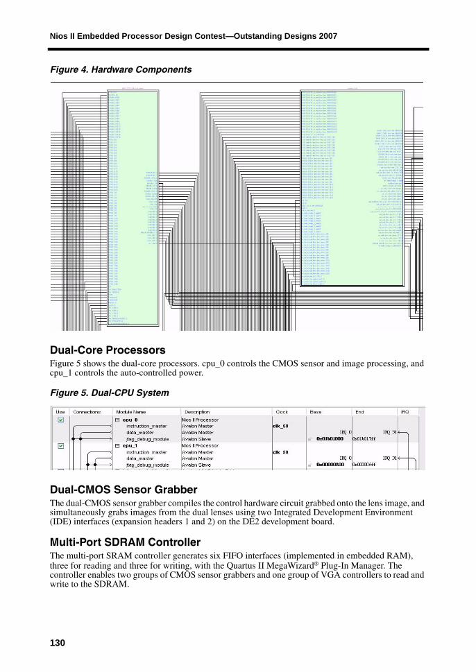
Major Hardware ComponentsWe created the dual-CPU core with SOPC Builder, designed hardware circuit components in Verilog HDL, conducted timing simulation and verification with waveforms, and connected the CPU using the PIO method. In addition to the peripheral circuits provided by SOPC Builder, the design has a dual-CMOS sensor image capturing circuit, a 6-port SDRAM controller, and a VGA controller that contains the image processing circuit. Figure 4 shows the hardware circuit, which has been integrated into a bigger module (the block on the left of Figure 4). This block is a dual-CPU module created with SOPC Builder.
129
Nios II Embedded Processor Design Contest—Outstanding Designs 2007
Figure 4. Hardware Components
Dual-Core ProcessorsFigure 5 shows the dual-core processors. cpu_0 controls the CMOS sensor and image processing, and cpu_1 controls the auto-controlled power.
Figure 5. Dual-CPU System
Dual-CMOS Sensor GrabberThe dual-CMOS sensor grabber compiles the control hardware circuit grabbed onto the lens image, and simultaneously grabs images from the dual lenses using two Integrated Development Environment (IDE) interfaces (expansion headers 1 and 2) on the DE2 development board.
Multi-Port SDRAM ControllerThe multi-port SRAM controller generates six FIFO interfaces (implemented in embedded RAM), three for reading and three for writing, with the Quartus II MegaWizard® Plug-In Manager. The controller enables two groups of CMOS sensor grabbers and one group of VGA controllers to read and write to the SDRAM.
130
Smart Self-Controlled Vehicle for Motion Image Tracking
VGA Controller and Image ProcessingThe VGA controller and image processing function write the hardware control circuit output by the VGA monitor, generate image statistics on the X- and Y-axis while outputting images, and store the results in on-chip memory for the Nios II processor to read.
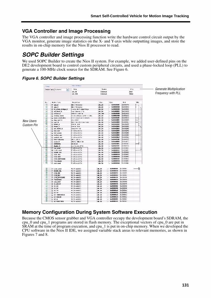
SOPC Builder SettingsWe used SOPC Builder to create the Nios II system. For example, we added user-defined pins on the DE2 development board to control custom peripheral circuits, and used a phase-locked loop (PLL) to generate a 100-MHz clock source for the SDRAM. See Figure 6.
Figure 6. SOPC Builder Settings
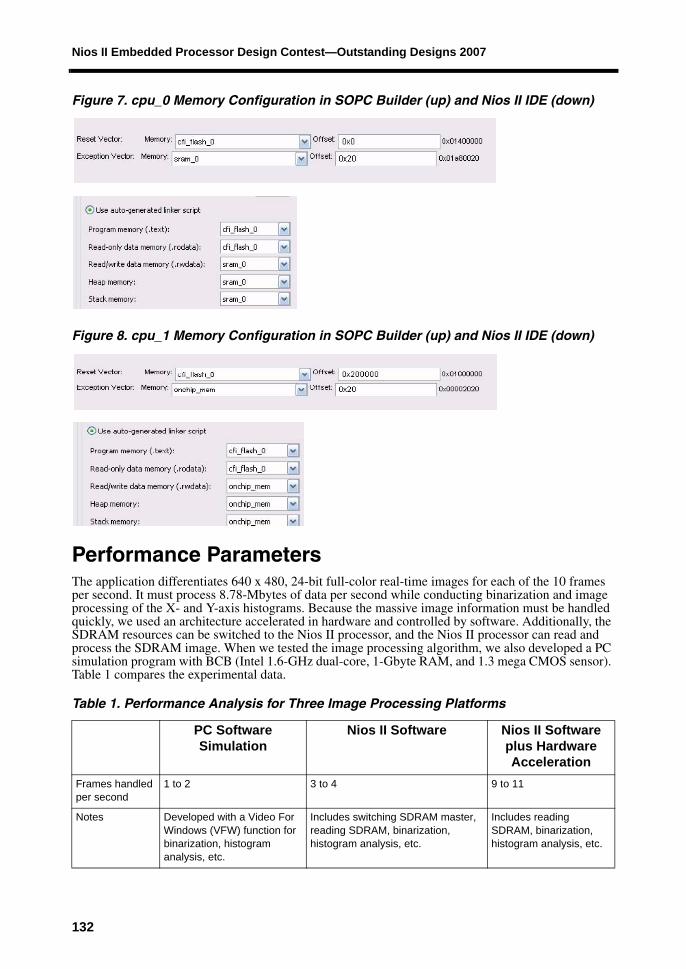
Memory Configuration During System Software ExecutionBecause the CMOS sensor grabber and VGA controller occupy the development board’s SDRAM, the cpu_0 and cpu_1 programs are stored in flash memory. The exceptional vectors of cpu_0 are put in SRAM at the time of program execution, and cpu_1 is put in on-chip memory. When we developed the CPU software in the Nios II IDE, we assigned variable stack areas to relevant memories, as shown in Figures 7 and 8.
New Users
Generate Multiplication
Custom Pin
Frequency with PLL
131
Nios II Embedded Processor Design Contest—Outstanding Designs 2007
Figure 7. cpu_0 Memory Configuration in SOPC Builder (up) and Nios II IDE (down)
Figure 8. cpu_1 Memory Configuration in SOPC Builder (up) and Nios II IDE (down)
Performance ParametersThe application differentiates 640 x 480, 24-bit full-color real-time images for each of the 10 frames per second. It must process 8.78-Mbytes of data per second while conducting binarization and image processing of the X- and Y-axis histograms. Because the massive image information must be handled quickly, we used an architecture accelerated in hardware and controlled by software. Additionally, the SDRAM resources can be switched to the Nios II processor, and the Nios II processor can read and process the SDRAM image. When we tested the image processing algorithm, we also developed a PC simulation program with BCB (Intel 1.6-GHz dual-core, 1-Gbyte RAM, and 1.3 mega CMOS sensor). Table 1 compares the experimental data.
Table 1. Performance Analysis for Three Image Processing Platforms
PC Software Simulation
Nios II Software Nios II Software plus Hardware Acceleration
Frames handled per second
1 to 2 3 to 4 9 to 11
Notes Developed with a Video For Windows (VFW) function for binarization, histogram analysis, etc.
Includes switching SDRAM master, reading SDRAM, binarization, histogram analysis, etc.
Includes reading SDRAM, binarization, histogram analysis, etc.
132
Smart Self-Controlled Vehicle for Motion Image Tracking
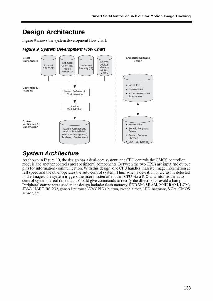
Design ArchitectureFigure 9 shows the system development flow chart.
Figure 9. System Development Flow Chart
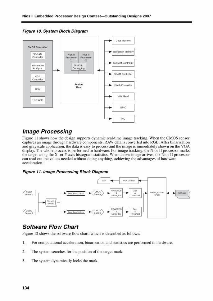
System ArchitectureAs shown in Figure 10, the design has a dual-core system: one CPU controls the CMOS controller module and another controls most peripheral components. Between the two CPUs are input and output pins for information communication. With this design, one CPU handles massive image information at full speed and the other operates the auto control system. Thus, when a deviation or a crash is detected in the images, the system triggers the intermission of another CPU via a PIO and informs the auto control system in real time that it should give commands to rectify the direction or avoid a bump. Peripheral components used in the design include: flash memory, SDRAM, SRAM, M4K RAM, LCM, JTAG-UART, RS-232, general-purpose I/O (GPIO), button, switch, timer, LED, segment, VGA, CMOS sensor, etc.
SelectComponents
Customize &Integrate
SystemVerification &Construction
ExternalCPU/DSP
Soft-CoreCPU Nios/
Nios IIProcessor
IntellectualProperty (IP)
ExternalDevices,Memory,ASSPs,ASICs
System Definition &Customization
AvalonSwitch Fabric
System ComponentsAvalon Switch Fabric
(VHDL or Verilog HDL)Testbench Environment
Embedded SoftwareDesign
RTOS DevelopmentEnvironment
OS/RTOS Kernels
Nios II IDE
Preferred IDE
Header FilesGeneric PeripheralDriversCustom SoftwareLibraries
133
Nios II Embedded Processor Design Contest—Outstanding Designs 2007
Figure 10. System Block Diagram
Image ProcessingFigure 11 shows how the design supports dynamic real-time image tracking. When the CMOS sensor captures an image through hardware components, RAW data is converted into RGB. After binarization and grayscale application, the data is easy to process and the image is immediately shown on the VGA display. The whole process is performed in hardware. For image tracking, the Nios II processor marks the target using the X- or Y-axis histogram statistics. When a new image arrives, the Nios II processor can read out the values needed without doing anything, achieving the advantages of hardware acceleration.
Figure 11. Image Processing Block Diagram
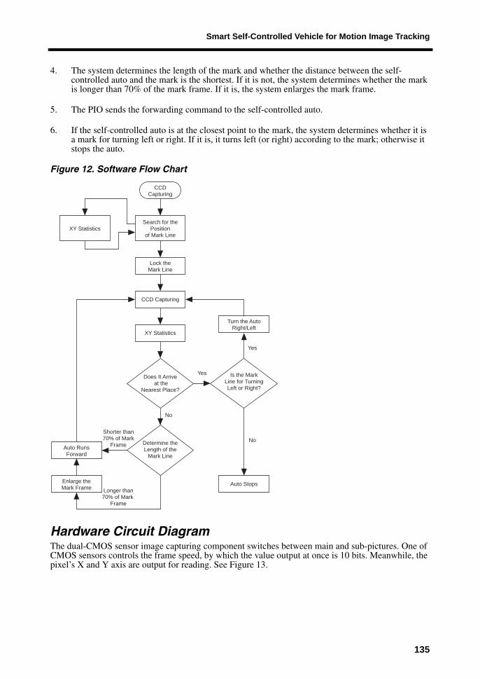
Software Flow ChartFigure 12 shows the software flow chart, which is described as follows:
1. For computational acceleration, binarization and statistics are performed in hardware.
2. The system searches for the position of the target mark.
3. The system dynamically locks the mark.
CMOS Controller
SDRAMController
VGAController
Gray
Threshold
Nios IIProcessor
01
Nios IIProcessor
02
On-ChipDebugging
AvalonBus
Data Memory
Instruction Memory
SDRAM Controller
SRAM Controller
Flash Controller
M4K RAM
GPIO
PIO
InformationAnalysis
CMOSSensor 1
CMOSSensor 2
SensorSwitch
VGA
Data Bus 32 Bits
Data Bus 16 Bits
CMOSCapture
CMOSCapture
VGA Control
RAW2RGB&
Mirror_Col
RAW2RGB&
Mirror_Col
Gray&
Threshold
Gray&
Threshold
Sdram_Control(6Port)
SDRAM
134
Smart Self-Controlled Vehicle for Motion Image Tracking
4. The system determines the length of the mark and whether the distance between the self-controlled auto and the mark is the shortest. If it is not, the system determines whether the mark is longer than 70% of the mark frame. If it is, the system enlarges the mark frame.
5. The PIO sends the forwarding command to the self-controlled auto.
6. If the self-controlled auto is at the closest point to the mark, the system determines whether it is a mark for turning left or right. If it is, it turns left (or right) according to the mark; otherwise it stops the auto.
Figure 12. Software Flow Chart
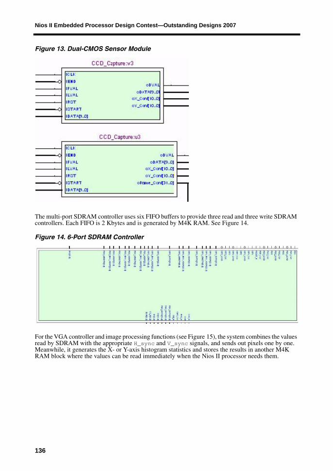
Hardware Circuit DiagramThe dual-CMOS sensor image capturing component switches between main and sub-pictures. One of CMOS sensors controls the frame speed, by which the value output at once is 10 bits. Meanwhile, the pixel’s X and Y axis are output for reading. See Figure 13.
CCD Capturing
XY StatisticsSearch for the
Positionof Mark Line
Lock theMark Line
CCD Capturing
XY Statistics
Turn the AutoRight/Left
Auto RunsForward
Enlarge theMark Frame
Does It Arrive at the
Nearest Place?
Determine theLength of the
Mark Line
No
Is the MarkLine for TurningLeft or Right?
Auto Stops
Shorter than70% of Mark
Frame
Longer than70% of Mark
Frame
Yes
No
Yes
135
Nios II Embedded Processor Design Contest—Outstanding Designs 2007
Figure 13. Dual-CMOS Sensor Module
The multi-port SDRAM controller uses six FIFO buffers to provide three read and three write SDRAM controllers. Each FIFO is 2 Kbytes and is generated by M4K RAM. See Figure 14.
Figure 14. 6-Port SDRAM Controller
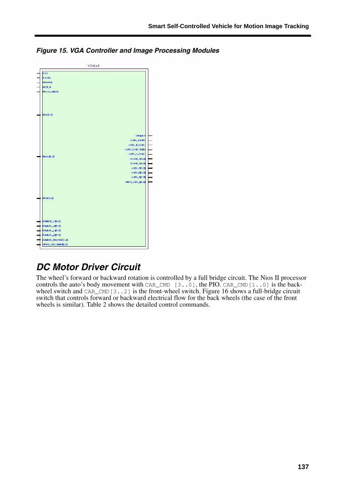
For the VGA controller and image processing functions (see Figure 15), the system combines the values read by SDRAM with the appropriate H_sync and V_sync signals, and sends out pixels one by one. Meanwhile, it generates the X- or Y-axis histogram statistics and stores the results in another M4K RAM block where the values can be read immediately when the Nios II processor needs them.
136
Smart Self-Controlled Vehicle for Motion Image Tracking
Figure 15. VGA Controller and Image Processing Modules
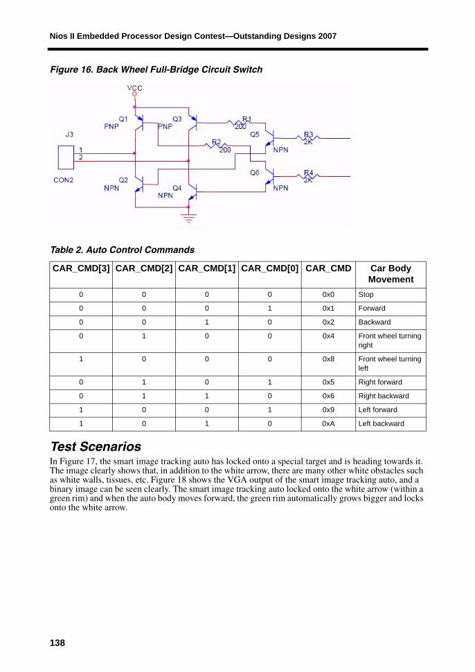
DC Motor Driver CircuitThe wheel’s forward or backward rotation is controlled by a full bridge circuit. The Nios II processor controls the auto’s body movement with CAR_CMD [3..0], the PIO. CAR_CMD[1..0] is the back-wheel switch and CAR_CMD[3..2] is the front-wheel switch. Figure 16 shows a full-bridge circuit switch that controls forward or backward electrical flow for the back wheels (the case of the front wheels is similar). Table 2 shows the detailed control commands.
137
Nios II Embedded Processor Design Contest—Outstanding Designs 2007
Figure 16. Back Wheel Full-Bridge Circuit Switch
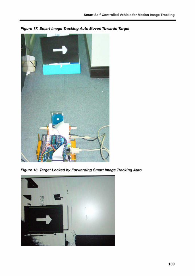
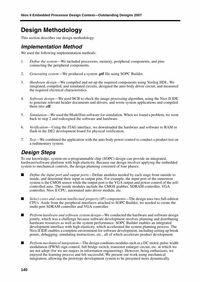
Test ScenariosIn Figure 17, the smart image tracking auto has locked onto a special target and is heading towards it. The image clearly shows that, in addition to the white arrow, there are many other white obstacles such as white walls, tissues, etc. Figure 18 shows the VGA output of the smart image tracking auto, and a binary image can be seen clearly. The smart image tracking auto locked onto the white arrow (within a green rim) and when the auto body moves forward, the green rim automatically grows bigger and locks onto the white arrow.
Table 2. Auto Control Commands
CAR_CMD[3] CAR_CMD[2] CAR_CMD[1] CAR_CMD[0] CAR_CMD Car Body Movement
0 0 0 0 0x0 Stop
0 0 0 1 0x1 Forward
0 0 1 0 0x2 Backward
0 1 0 0 0x4 Front wheel turning right
1 0 0 0 0x8 Front wheel turning left
0 1 0 1 0x5 Right forward
0 1 1 0 0x6 Right backward
1 0 0 1 0x9 Left forward
1 0 1 0 0xA Left backward
138
Smart Self-Controlled Vehicle for Motion Image Tracking
Figure 17. Smart Image Tracking Auto Moves Towards Target
Figure 18. Target Locked by Forwarding Smart Image Tracking Auto
139
Nios II Embedded Processor Design Contest—Outstanding Designs 2007
Design MethodologyThis section describes our design methodology.
Implementation MethodWe used the following implementation methods:
1. Define the system—We included processors, memory, peripheral components, and pins connecting the peripheral components.
2. Generating system—We produced a system .ptf file using SOPC Builder.
3. Hardware design—We compiled and set up the required components using Verilog HDL. We integrated, compiled, and simulated circuits, designed the auto body driver circuit, and measured the required electrical characteristics.
4. Software design—We used BCB to check the image processing algorithm, using the Nios II IDE to generate relevant header documents and drivers, and wrote system applications and compiled them into .elf.
5. Simulation—We used the ModelSim software for simulation. When we found a problem, we went back to step 2 and redesigned the software and hardware.
6. Verification—Using the JTAG interface, we downloaded the hardware and software to RAM or flash in the DE2 development board for physical verification.
7. Test—We combined the application with the auto body power control to conduct a product test on a rudimentary system.
Design StepsTo our knowledge, system-on-a-programmable chip (SOPC) design can provide an integrated, hardware/software platform with high elasticity. Because our design involves applying the embedded system to mechanical controls, the design planning consisted of four phases:
■ Define the input port and output ports—Define modules needed by each stage from outside to inside, and determine their input or output pins. For example, the input port of the outermost system is the CMOS sensor while the output port is the VGA output and power control of the self-controlled auto. The inside modules include the CMOS grabber, SDRAM controller, VGA controller, Nios II CPU, automated auto driver module, etc.
■ Select cores and custom intellectual property (IP) components—The design uses two full-edition CPUs. Aside from the peripheral interfaces attached to SOPC Builder, we needed to create the multi-port SDRAM controller and VGA controller.
■ Perform hardware and software system design—We conducted the hardware and software design jointly, which was a challenge because software development involves planning and distributing hardware resources as well as the system performance. SOPC Builder enables an integrated development interface with high elasticity, which accelerated the system planning process. The Nios II IDE enables a complete environment for software development, including setting up break points, debugging, simulating instructions, etc., all of which accelerate product development.
■ Perform mechanical integration—The design combines modules such as a DC motor, pulse-width modulation (PWM) sign control, full bridge switch, transistor enlarger circuit, etc. at which we are not adept (for we are majors in information engineering). However, being enthusiasts, we enjoyed the learning process and felt successful. We present our work using mechanical integration, allowing the prototype development system to be presented more dynamically.
140
Smart Self-Controlled Vehicle for Motion Image Tracking
Design FeaturesOur design has the following features:
■ Dual-CPU communication—We used two CPUs to control and manage the smart image tracking system and obtained dual-CPU communication with I/O and interrupts.
■ 100% hardware and software implementation—We perfectly implemented the smart image tracking auto functions, such as target searching, target locking, auto body automated leading control, automated stop, etc.
■ Custom peripherals with hardware acceleration—At first we developed the CMOS sensor controller and SDRAM controller with a hardware circuit; we stored the CMOS sensor image directly in SDRAM and made the SDRAM a Nios II master. But the experiments showed that the speed could not meet our requirements because the Nios II processor spent too much time reading SDRAM and image processing. Therefore, we developed circuits combing the VGA controller with image processing and implemented the VGA output and image processing at the same time. This design delivered the effect that we wanted.
■ Three IP functions connected outside of the Nios II processor—Because the Nios II processor can be set with elasticity, PIO pins communicating outside can be easily designed according to the user’s needs. By combining the hardware circuits such as the VGA controller, multi-port SDRAM controller, image processing function, etc., we improved the performance of the massive image data processing.
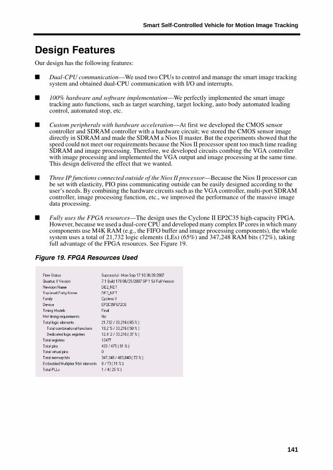
■ Fully uses the FPGA resources—The design uses the Cyclone II EP2C35 high-capacity FPGA. However, because we used a dual-core CPU and developed many complex IP cores in which many components use M4K RAM (e.g., the FIFO buffer and image processing components), the whole system uses a total of 21,732 logic elements (LEs) (65%) and 347,248 RAM bits (72%), taking full advantage of the FPGA resources. See Figure 19.
Figure 19. FPGA Resources Used
141
Nios II Embedded Processor Design Contest—Outstanding Designs 2007
ConclusionWe benefited greatly from participating in the Altera Nios II Embedded Processor Design Contest 2007. We divided our work into systems integration, hardware development, and control circuit design, which are described as follows:
■ System integration—Thanks to the Nios II IDE and convenient SOPC Builder, we implemented the soft-core CPU in the prototype machine with a flexible design, accelerating the development process. With quick executive efficiency provided by a dual-core PC, the new Quartus II version 7.1 software and Nios II IDE version 7.1 largely reduced the time we had to wait for hardware integration or software compilation.
■ Hardware development—Thanks to the contest, we are now acquainted with SDRAM controller design. With timing adjustments, we designed multiple high-speed peripherals that share one SDRAM device. Besides the VGA controller, we learned how to process real-time images while outputting image pixels, etc.
■ Control circuit design—We are honored to participate in this Nios II design contest. Although the challenge of working with unfamiliar mechanical controls gave us a lot of trouble, we finally saw the clumsy, smart image-tracking auto operate on various surfaces. This contest brought all members in our lab together to solve problems jointly. Thank you for providing young students with such a precious opportunity to make our dreams come true.
142