Embed Size (px)
Citation preview
1
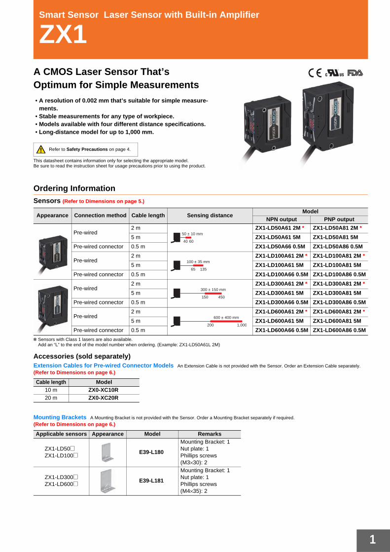
Smart Sensor Laser Sensor with Built-in Amplifier
ZX1A CMOS Laser Sensor That’s Optimum for Simple Measurements• A resolution of 0.002 mm that’s suitable for simple measure-
ments.• Stable measurements for any type of workpiece.• Models available with four different distance specifications.• Long-distance model for up to 1,000 mm.
This datasheet contains information only for selecting the appropriate model.Be sure to read the instruction sheet for usage precautions prior to using the product.
Refer to Safety Precautions on page 4.
Ordering InformationSensors (Refer to Dimensions on page 5.)
* Sensors with Class 1 lasers are also available.Add an “L” to the end of the model number when ordering. (Example: ZX1-LD50A61L 2M)
Accessories (sold separately)Extension Cables for Pre-wired Connector Models An Extension Cable is not provided with the Sensor. Order an Extension Cable separately.
(Refer to Dimensions on page 6.)
Mounting Brackets A Mounting Bracket is not provided with the Sensor. Order a Mounting Bracket separately if required.
(Refer to Dimensions on page 6.)
Appearance Connection method Cable length Sensing distanceModel
NPN output PNP output
Pre-wired2 m ZX1-LD50A61 2M * ZX1-LD50A81 2M *
5 m ZX1-LD50A61 5M ZX1-LD50A81 5M
Pre-wired connector 0.5 m ZX1-LD50A66 0.5M ZX1-LD50A86 0.5M
Pre-wired2 m ZX1-LD100A61 2M * ZX1-LD100A81 2M *
5 m ZX1-LD100A61 5M ZX1-LD100A81 5M
Pre-wired connector 0.5 m ZX1-LD100A66 0.5M ZX1-LD100A86 0.5M
Pre-wired2 m ZX1-LD300A61 2M * ZX1-LD300A81 2M *
5 m ZX1-LD300A61 5M ZX1-LD300A81 5M
Pre-wired connector 0.5 m ZX1-LD300A66 0.5M ZX1-LD300A86 0.5M
Pre-wired2 m ZX1-LD600A61 2M * ZX1-LD600A81 2M *
5 m ZX1-LD600A61 5M ZX1-LD600A81 5M
Pre-wired connector 0.5 m ZX1-LD600A66 0.5M ZX1-LD600A86 0.5M
Cable length Model10 m ZX0-XC10R20 m ZX0-XC20R
Applicable sensors Appearance Model Remarks
ZX1-LD50@ZX1-LD100@ E39-L180
Mounting Bracket: 1Nut plate: 1Phillips screws(M3×30): 2
ZX1-LD300@ZX1-LD600@ E39-L181
Mounting Bracket: 1Nut plate: 1Phillips screws(M4×35): 2
40
50 ± 10 mm
60
65
100 ± 35 mm
135
150
300 ± 150 mm
450
200
600 ± 400 mm
1,000
ZX1
2
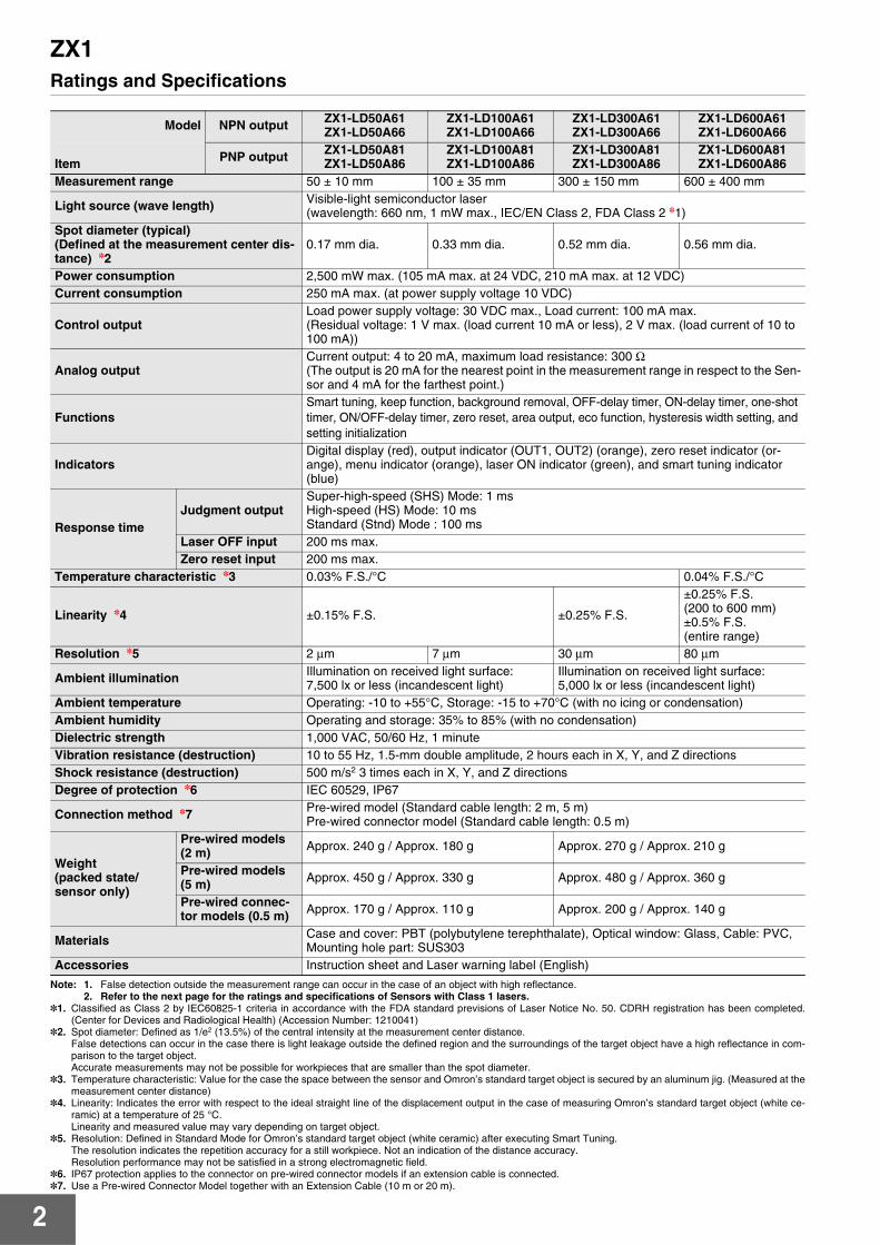
Ratings and Specifications
Note: 1. False detection outside the measurement range can occur in the case of an object with high reflectance.2. Refer to the next page for the ratings and specifications of Sensors with Class 1 lasers.
*1. Classified as Class 2 by IEC60825-1 criteria in accordance with the FDA standard previsions of Laser Notice No. 50. CDRH registration has been completed.(Center for Devices and Radiological Health) (Accession Number: 1210041)
*2. Spot diameter: Defined as 1/e2 (13.5%) of the central intensity at the measurement center distance.False detections can occur in the case there is light leakage outside the defined region and the surroundings of the target object have a high reflectance in com-parison to the target object.Accurate measurements may not be possible for workpieces that are smaller than the spot diameter.
*3. Temperature characteristic: Value for the case the space between the sensor and Omron’s standard target object is secured by an aluminum jig. (Measured at themeasurement center distance)
*4. Linearity: Indicates the error with respect to the ideal straight line of the displacement output in the case of measuring Omron’s standard target object (white ce-ramic) at a temperature of 25 °C. Linearity and measured value may vary depending on target object.
*5. Resolution: Defined in Standard Mode for Omron’s standard target object (white ceramic) after executing Smart Tuning.The resolution indicates the repetition accuracy for a still workpiece. Not an indication of the distance accuracy.Resolution performance may not be satisfied in a strong electromagnetic field.
*6. IP67 protection applies to the connector on pre-wired connector models if an extension cable is connected.*7. Use a Pre-wired Connector Model together with an Extension Cable (10 m or 20 m).
Model NPN output ZX1-LD50A61ZX1-LD50A66
ZX1-LD100A61ZX1-LD100A66
ZX1-LD300A61ZX1-LD300A66
ZX1-LD600A61ZX1-LD600A66
Item PNP output ZX1-LD50A81ZX1-LD50A86
ZX1-LD100A81ZX1-LD100A86
ZX1-LD300A81ZX1-LD300A86
ZX1-LD600A81ZX1-LD600A86
Measurement range 50 ± 10 mm 100 ± 35 mm 300 ± 150 mm 600 ± 400 mm
Light source (wave length) Visible-light semiconductor laser(wavelength: 660 nm, 1 mW max., IEC/EN Class 2, FDA Class 2 *1)
Spot diameter (typical)(Defined at the measurement center dis-tance) *2
0.17 mm dia. 0.33 mm dia. 0.52 mm dia. 0.56 mm dia.
Power consumption 2,500 mW max. (105 mA max. at 24 VDC, 210 mA max. at 12 VDC)Current consumption 250 mA max. (at power supply voltage 10 VDC)
Control outputLoad power supply voltage: 30 VDC max., Load current: 100 mA max.(Residual voltage: 1 V max. (load current 10 mA or less), 2 V max. (load current of 10 to 100 mA))
Analog outputCurrent output: 4 to 20 mA, maximum load resistance: 300 Ω(The output is 20 mA for the nearest point in the measurement range in respect to the Sen-sor and 4 mA for the farthest point.)
FunctionsSmart tuning, keep function, background removal, OFF-delay timer, ON-delay timer, one-shot timer, ON/OFF-delay timer, zero reset, area output, eco function, hysteresis width setting, and setting initialization
IndicatorsDigital display (red), output indicator (OUT1, OUT2) (orange), zero reset indicator (or-ange), menu indicator (orange), laser ON indicator (green), and smart tuning indicator (blue)
Response timeJudgment output
Super-high-speed (SHS) Mode: 1 msHigh-speed (HS) Mode: 10 msStandard (Stnd) Mode : 100 ms
Laser OFF input 200 ms max.Zero reset input 200 ms max.
Temperature characteristic *3 0.03% F.S./°C 0.04% F.S./°C
Linearity *4 ±0.15% F.S. ±0.25% F.S.
±0.25% F.S. (200 to 600 mm)±0.5% F.S. (entire range)
Resolution *5 2 μm 7 μm 30 μm 80 μm
Ambient illumination Illumination on received light surface: 7,500 lx or less (incandescent light)
Illumination on received light surface: 5,000 lx or less (incandescent light)
Ambient temperature Operating: -10 to +55°C, Storage: -15 to +70°C (with no icing or condensation)Ambient humidity Operating and storage: 35% to 85% (with no condensation)Dielectric strength 1,000 VAC, 50/60 Hz, 1 minuteVibration resistance (destruction) 10 to 55 Hz, 1.5-mm double amplitude, 2 hours each in X, Y, and Z directionsShock resistance (destruction) 500 m/s2 3 times each in X, Y, and Z directionsDegree of protection *6 IEC 60529, IP67
Connection method *7 Pre-wired model (Standard cable length: 2 m, 5 m)Pre-wired connector model (Standard cable length: 0.5 m)
Weight(packed state/sensor only)
Pre-wired models (2 m) Approx. 240 g / Approx. 180 g Approx. 270 g / Approx. 210 g
Pre-wired models (5 m) Approx. 450 g / Approx. 330 g Approx. 480 g / Approx. 360 g
Pre-wired connec-tor models (0.5 m) Approx. 170 g / Approx. 110 g Approx. 200 g / Approx. 140 g
Materials Case and cover: PBT (polybutylene terephthalate), Optical window: Glass, Cable: PVC, Mounting hole part: SUS303
Accessories Instruction sheet and Laser warning label (English)

ZX1
3
Ratings and Specifications of Sensors with Class 1 lasers (ZX1-LD@L)The ratings and specifications that are different from those of the Sensors with Class 2 lasers are given below.
Accession Number: 1210041
Engineering Data (Typical)
Angle Characteristic
Linearity Characteristic for Different Materials
Note: 1. Measurement conditions for the ZX1-LD@@: Ambient temperature of 25°C in Standard Mode after executing Smart Tuning.2. The ambient conditions or workpiece may adversely affect the engineering data of the [email protected]. The X-axis displacement indicates the measurement distance displayed on a digital display.
The measurement distance displayed on a digital display takes the measurement center distance as 0 and displays the near side of the Sensor as positive and the far side as negative.
ModelItem
ZX1-LD50A61L/ZX1-LD50A81LZX1-LD100A61L/ZX1-LD100A81L
ZX1-LD300A61L/ZX1-LD300A81LZX1-LD600A61L/ZX1-LD600A81L
FDA Class Class1 0.24mW max.IEC/EN Class Class1 0.24mW max.Ambient illumination Illumination on received light surface 5,000 lx or less (incandescent light) Illumination on received light surface 2,500 lx or less (incandescent light)Connection method Pre-wired model (2 m)Accessories Instruction sheet and Explanatory label (English), FDA certification label
ZX1-LD50@Side-to-side Inclination
ZX1-LD100@Side-to-side Inclination
ZX1-LD300@Side-to-side Inclination
ZX1-LD600@Side-to-side Inclination
ZX1-LD50@Front-to-back Inclination
ZX1-LD100@Front-to-back Inclination
ZX1-LD300@Front-to-back Inclination
ZX1-LD600@Front-to-back Inclination
ZX1-LD50@ ZX1-LD100@ ZX1-LD300@ ZX1-LD600@
Err
or (
%F.
S.) 3
2
1
0
–1
–2
–30–10–20–30–40–50 10 20 30 40 50
Angle of Inclination (°)
White ceramicSUS304, mirror finishBlack rubber
+ Inclination− Inclination
Measurement center distance E
rror
(%
F.S
.) 3
2
1
0
–1
–2
–30–10–20–30–40–50 10 20 30 40 50
Angle of Inclination (°)
White ceramicSUS304, mirror finishBlack rubber
+ Inclination− Inclination
Measurement center distance E
rror
(%
F.S
.) 3
2
1
0
–1
–2
–30–10–20–30–40–50 10 20 30 40 50
Angle of Inclination (°)
White ceramicSUS304, mirror finishBlack rubber
+ Inclination− Inclination
Measurement center distance E
rror
(%
F.S
.) 3
2
1
0
–1
–2
–30–10–20–30–40–50 10 20 30 40 50
Angle of Inclination (°)
White ceramicSUS304, mirror finishBlack rubber
+ Inclination− Inclination
Measurement center distance
–2.0
–1.5
–1.0
–0.5
0.0
0.5
1.0
1.5
2.0
–10 10–8 –6 –4 –2 0 2 4 6 8
Err
or (
%F.
S.)
White ceramicSUS304, mirror finishSubstrate
Displacement (mm)
Measurementcenter distance
FAR side NEAR side
–2.0
–1.5
–1.0
–0.5
0.0
0.5
1.0
1.5
2.0
–35 35251550–5–15–25
Err
or (
%F.
S.)
White ceramicSUS304, mirror finishSubstrate
Displacement (mm)
Measurementcenter distance
FAR side NEAR side
–2.0
–1.5
–1.0
–0.5
0.0
0.5
1.0
1.5
2.0
–150 100 150500–50–100
Err
or (
%F.
S.)
White ceramicSUS304, mirror finishSubstrate
Displacement (mm)
Measurementcenter distance
FAR side NEAR side
Err
or (
%F.
S.)
Displacement (mm)
Measurementcenter distance
–2.0
–1.5
–1.0
–0.5
0.0
0.5
1.0
1.5
2.0
–400 100 4003002000–100–200–300
FAR side NEAR side
White ceramicSUS304, mirror finishSubstrate
Displacement (mm)Sensor
FAR side NEAR side
Measurement center distance
Measurement diagram
Workpiece
ZX1
4
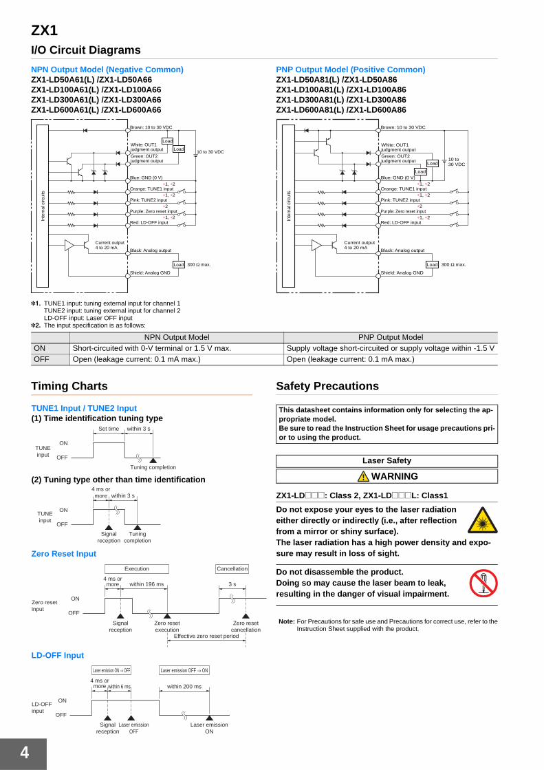
I/O Circuit Diagrams
NPN Output Model (Negative Common)ZX1-LD50A61(L) /ZX1-LD50A66ZX1-LD100A61(L) /ZX1-LD100A66ZX1-LD300A61(L) /ZX1-LD300A66ZX1-LD600A61(L) /ZX1-LD600A66
PNP Output Model (Positive Common)ZX1-LD50A81(L) /ZX1-LD50A86ZX1-LD100A81(L) /ZX1-LD100A86ZX1-LD300A81(L) /ZX1-LD300A86ZX1-LD600A81(L) /ZX1-LD600A86
*1. TUNE1 input: tuning external input for channel 1TUNE2 input: tuning external input for channel 2LD-OFF input: Laser OFF input
*2. The input specification is as follows:
Timing Charts Safety Precautions
ZX1-LD@@@: Class 2, ZX1-LD@@@L: Class1
Do not expose your eyes to the laser radiation either directly or indirectly (i.e., after reflection from a mirror or shiny surface).The laser radiation has a high power density and expo-sure may result in loss of sight.
Do not disassemble the product.Doing so may cause the laser beam to leak, resulting in the danger of visual impairment.
Note: For Precautions for safe use and Precautions for correct use, refer to theInstruction Sheet supplied with the product.
Brown: 10 to 30 VDC
10 to 30 VDC
White: OUT1judgment output
Green: OUT2judgment output
Blue: GND (0 V)
Orange: TUNE1 input∗1, ∗2
∗1, ∗2
∗1, ∗2
∗2Pink: TUNE2 input
Purple: Zero reset input
Red: LD-OFF input
Black: Analog output
300 Ω max.
Shield: Analog GND
Current output4 to 20 mA
Inte
rnal
circ
uits
Load
Load
Load
Brown: 10 to 30 VDC
10 to 30 VDC
White: OUT1judgment outputGreen: OUT2judgment output
Blue: GND (0 V)
Orange: TUNE1 input∗1, ∗2
∗1, ∗2
∗1, ∗2
∗2Pink: TUNE2 input
Purple: Zero reset input
Red: LD-OFF input
Black: Analog output
300 Ω max.
Shield: Analog GND
Current output4 to 20 mA
Inte
rnal
circ
uits
Load
Load
Load
NPN Output Model PNP Output ModelON Short-circuited with 0-V terminal or 1.5 V max. Supply voltage short-circuited or supply voltage within -1.5 VOFF Open (leakage current: 0.1 mA max.) Open (leakage current: 0.1 mA max.)
ON
Set time within 3 s
OFF
TUNE input
Tuning completion
within 3 s
ON
OFF
TUNE input
4 ms or more
Signal reception
Tuning completion
Execution Cancellation
ON
within 196 ms 3 s
OFF
Effective zero reset period
Zero reset input
4 ms or more
Signal reception
Zero reset execution
Zero reset cancellation
Laser emission ON → OFF Laser emission OFF → ON
ON
OFF
LD-OFF input
within 6 ms within 200 ms4 ms or more
Signal reception
Laser emission OFF
Laser emission ON
TUNE1 Input / TUNE2 Input(1) Time identification tuning type
(2) Tuning type other than time identification
Zero Reset Input
LD-OFF Input
This datasheet contains information only for selecting the ap-propriate model.Be sure to read the Instruction Sheet for usage precautions pri-or to using the product.
Laser Safety
WARNING
ZX1
5
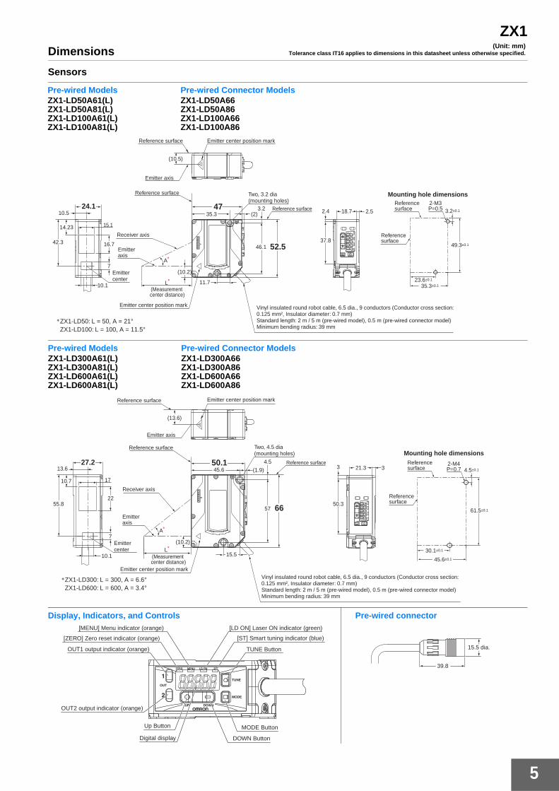
Dimensions
Sensors
(Unit: mm)Tolerance class IT16 applies to dimensions in this datasheet unless otherwise specified.
* ZX1-LD50: L = 50, A = 21° ZX1-LD100: L = 100, A = 11.5°
Reference surface
Reference surface
Reference surface Emitter center position mark
Emitter axis
Two, 3.2 dia (mounting holes)
10.5
15.1
42.3
14.23
Emitter center
7
16.7
10.1
Emitter axis
Receiver axis
(10.5)
(2) 35.3 3.2 47
52.5 46.1
L*
(Measurement center distance)
A*
(10.2)
11.7
24.1
Mounting hole dimensions
Emitter center position mark Vinyl insulated round robot cable, 6.5 dia., 9 conductors (Conductor cross section: 0.125 mm², Insulator diameter: 0.7 mm)Standard length: 2 m / 5 m (pre-wired model), 0.5 m (pre-wired connector model)Minimum bending radius: 39 mm
2.5
37.8
2.4 18.7
2-M3 P=0.5
Reference surface
Reference surface
23.6±0.1
3.2±0.1
35.3±0.1
49.3±0.1
Pre-wired ModelsZX1-LD50A61(L)ZX1-LD50A81(L)ZX1-LD100A61(L)ZX1-LD100A81(L)
Pre-wired Connector ModelsZX1-LD50A66ZX1-LD50A86ZX1-LD100A66ZX1-LD100A86
(13.6)
50.1 (1.9)
4.5 45.6
57 66
15.5 L
*(10.2)
10.1
7
55.8
10.7
27.2
17
22
13.6
A*
* ZX1-LD300: L = 300, A = 6.6° ZX1-LD600: L = 600, A = 3.4°
Reference surface
Reference surface
Reference surface Emitter center position mark
Emitter axis
Two, 4.5 dia (mounting holes)
Emitter center
Emitter axis
Receiver axis
(Measurement center distance)
Mounting hole dimensions
Emitter center position mark Vinyl insulated round robot cable, 6.5 dia., 9 conductors (Conductor cross section: 0.125 mm², Insulator diameter: 0.7 mm)Standard length: 2 m / 5 m (pre-wired model), 0.5 m (pre-wired connector model)Minimum bending radius: 39 mm
3
50.3
3 21.3 2-M4 P=0.7 4.5±0.1
Reference surface
Reference surface
30.1±0.1
45.6±0.1
61.5±0.1
Pre-wired ModelsZX1-LD300A61(L)ZX1-LD300A81(L)ZX1-LD600A61(L)ZX1-LD600A81(L)
Pre-wired Connector ModelsZX1-LD300A66ZX1-LD300A86ZX1-LD600A66ZX1-LD600A86
Display, Indicators, and Controls Pre-wired connector
TUNE Button
[ST] Smart tuning indicator (blue)
[LD ON] Laser ON indicator (green)[MENU] Menu indicator (orange)
[ZERO] Zero reset indicator (orange)
OUT1 output indicator (orange)
OUT2 output indicator (orange)
Up Button
DOWN Button
MODE Button
Digital display
15.5 dia.
39.8
6
ZX1
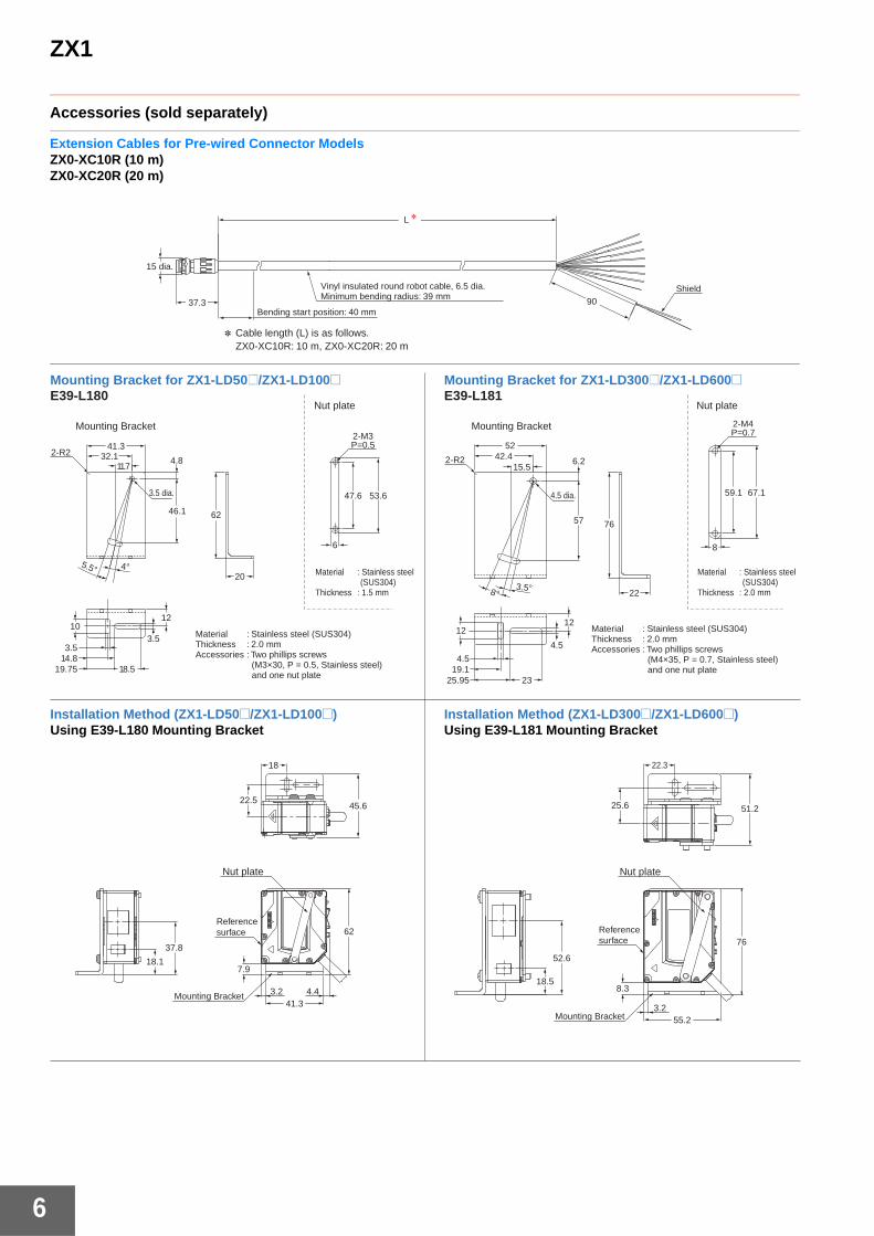
Accessories (sold separately)
Extension Cables for Pre-wired Connector ModelsZX0-XC10R (10 m)ZX0-XC20R (20 m)
Shield
37.3
15 dia.
L *
90
* Cable length (L) is as follows. ZX0-XC10R: 10 m, ZX0-XC20R: 20 m
Vinyl insulated round robot cable, 6.5 dia. Minimum bending radius: 39 mm
Bending start position: 40 mm
Mounting Bracket for ZX1-LD50@/ZX1-LD100@E39-L180
Installation Method (ZX1-LD50@/ZX1-LD100@)Using E39-L180 Mounting Bracket
Installation Method (ZX1-LD300@/ZX1-LD600@)Using E39-L181 Mounting Bracket
Mounting Bracket for ZX1-LD300@/ZX1-LD600@E39-L181
Material : Stainless steel (SUS304)Thickness : 2.0 mmAccessories : Two phillips screws (M3×30, P = 0.5, Stainless steel) and one nut plate
Material : Stainless steel (SUS304)Thickness : 2.0 mmAccessories : Two phillips screws (M4×35, P = 0.7, Stainless steel) and one nut plate
Nut plate
Mounting Bracket Mounting Bracket
Nut plate
46.1
11.7
4°5.5°
41.332.1 4.8
62
3.5
18.5
3.5
10
19.7514.8
12
2-R2
20
47.6
6
53.6
P=0.52-M3
3.5°8°
15.5
57
5242.4 6.2
4.5 dia.
76
22
1212
4.5
19.14.5
25.95 23
8
67.159.1
P=0.72-M4
7.9
3.2
62
41.34.4
22.5
18
45.6
18.1
37.8
3.2
8.3
55.2
76
25.6
22.3
51.2
18.5
52.6
Reference surface Reference
surface
Mounting Bracket
Nut plate
Mounting Bracket
Nut plate
2-R2
3.5 dia.
Material : Stainless steel (SUS304)Thickness : 1.5 mm
Material : Stainless steel (SUS304)Thickness : 2.0 mm
READ AND UNDERSTAND THIS DOCUMENTPlease read and understand this document before using the products. Please consult your OMRON representative if you have any questions or comments.
WARRANTYOMRON’s exclusive warranty is that the products are free from defects in materials and workmanship for a period of one year (or other period if specified) from date of sale by OMRON.
OMRON MAKES NO WARRANTY OR REPRESENTATION, EXPRESS OR IMPLIED, REGARDING NON-INFRINGEMENT, MERCHANTABILITY, OR FITNESS FOR PARTICULARPURPOSE OF THE PRODUCTS. ANY BUYER OR USER ACKNOWLEDGES THAT THE BUYER OR USER ALONE HAS DETERMINED THAT THE PRODUCTS WILL SUITABLY MEETTHE REQUIREMENTS OF THEIR INTENDED USE. OMRON DISCLAIMS ALL OTHER WARRANTIES, EXPRESS OR IMPLIED.
LIMITATIONS OF LIABILITYOMRON SHALL NOT BE RESPONSIBLE FOR SPECIAL, INDIRECT, OR CONSEQUENTIAL DAMAGES, LOSS OF PROFITS OR COMMERCIAL LOSS IN ANY WAYCONNECTED WITH THE PRODUCTS, WHETHER SUCH CLAIM IS BASED ON CONTRACT, WARRANTY, NEGLIGENCE, OR STRICT LIABILITY.
In no event shall responsibility of OMRON for any act exceed the individual price of the product on which liability is asserted.
IN NO EVENT SHALL OMRON BE RESPONSIBLE FOR WARRANTY, REPAIR, OR OTHER CLAIMS REGARDING THE PRODUCTS UNLESS OMRON’S ANALYSISCONFIRMS THAT THE PRODUCTS WERE PROPERLY HANDLED, STORED, INSTALLED, AND MAINTAINED AND NOT SUBJECT TO CONTAMINATION, ABUSE, MISUSE,OR INAPPROPRIATE MODIFICATION OR REPAIR.
SUITABILITY FOR USETHE PRODUCTS CONTAINED IN THIS DOCUMENT ARE NOT SAFETY RATED. THEY ARE NOT DESIGNED OR RATED FOR ENSURING SAFETY OF PERSONS, ANDSHOULD NOT BE RELIED UPON AS A SAFETY COMPONENT OR PROTECTIVE DEVICE FOR SUCH PURPOSES. Please refer to separate catalogs for OMRON's safety ratedproducts.
OMRON shall not be responsible for conformity with any standards, codes, or regulations that apply to the combination of products in the customer’s application or use of theproduct.
At the customer’s request, OMRON will provide applicable third party certification documents identifying ratings and limitations of use that apply to the products. This information byitself is not sufficient for a complete determination of the suitability of the products in combination with the end product, machine, system, or other application or use.
The following are some examples of applications for which particular attention must be given. This is not intended to be an exhaustive list of all possible uses of the products, nor isit intended to imply that the uses listed may be suitable for the products:• Outdoor use, uses involving potential chemical contamination or electrical interference, or conditions or uses not described in this document.• Nuclear energy control systems, combustion systems, railroad systems, aviation systems, medical equipment, amusement machines, vehicles, safety equipment, and installations
subject to separate industry or government regulations.• Systems, machines, and equipment that could present a risk to life or property.
Please know and observe all prohibitions of use applicable to the products.
NEVER USE THE PRODUCTS FOR AN APPLICATION INVOLVING SERIOUS RISK TO LIFE OR PROPERTY WITHOUT ENSURING THAT THE SYSTEM AS A WHOLE HASBEEN DESIGNED TO ADDRESS THE RISKS, AND THAT THE OMRON PRODUCT IS PROPERLY RATED AND INSTALLED FOR THE INTENDED USE WITHIN THE OVERALLEQUIPMENT OR SYSTEM.
PERFORMANCE DATAPerformance data given in this document is provided as a guide for the user in determining suitability and does not constitute a warranty. It may represent the result of OMRON’stest conditions, and the users must correlate it to actual application requirements. Actual performance is subject to the OMRON Warranty and Limitations of Liability.
CHANGE IN SPECIFICATIONSProduct specifications and accessories may be changed at any time based on improvements and other reasons.
It is our practice to change model numbers when published ratings or features are changed, or when significant construction changes are made. However, some specifications ofthe product may be changed without any notice. When in doubt, special model numbers may be assigned to fix or establish key specifications for your application on your request.Please consult with your OMRON representative at any time to confirm actual specifications of purchased products.
DIMENSIONS AND WEIGHTSDimensions and weights are nominal and are not to be used for manufacturing purposes, even when tolerances are shown.
ERRORS AND OMISSIONSThe information in this document has been carefully checked and is believed to be accurate; however, no responsibility is assumed for clerical, typographical, or proofreadingerrors, or omissions.
PROGRAMMABLE PRODUCTSOMRON shall not be responsible for the user’s programming of a programmable product, or any consequence thereof.
COPYRIGHT AND COPY PERMISSIONThis document shall not be copied for sales or promotions without permission.
This document is protected by copyright and is intended solely for use in conjunction with the product. Please notify us before copying or reproducing this document in any manner,for any other purpose. If copying or transmitting this document to another, please copy or transmit it in its entirety.
ALL DIMENSIONS SHOWN ARE IN MILLIMETERS. To convert millimeters into inches, multiply by 0.03937. To convert grams into ounces, multiply by 0.03527.
Authorized Distributor:
In the interest of product improvement, specifications are subject to change without notice.
Cat. No. E416-E1-02Printed in Japan
0112(1111)
© OMRON Corporation 2011 All Rights Reserved.
OMRON Corporation Industrial Automation Company
OMRON ELECTRONICS LLC One Commerce Drive Schaumburg, IL 60173-5302 U.S.A. Tel: (1) 847-843-7900/Fax: (1) 847-843-7787
Regional Headquarters
OMRON EUROPE B.V. Sensor Business Unit Carl-Benz-Str. 4, D-71154 Nufringen, Germany Tel: (49) 7032-811-0/Fax: (49) 7032-811-199
Contact: www.ia.omron.com Tokyo, JAPAN
OMRON ASIA PACIFIC PTE. LTD. No. 438A Alexandra Road # 05-05/08 (Lobby 2), Alexandra Technopark, Singapore 119967 Tel: (65) 6835-3011/Fax: (65) 6835-2711
OMRON (CHINA) CO., LTD. Room 2211, Bank of China Tower, 200 Yin Cheng Zhong Road, PuDong New Area, Shanghai, 200120, China Tel: (86) 21-5037-2222/Fax: (86) 21-5037-2200
CSM_3_1_1114