Embed Size (px)
Citation preview

1
Smart Sensor Systems Smart Sensor Systems Integration: New ChallengesIntegration: New Challenges
Prof. Sergey Y. YurishProf. Sergey Y. YurishIFSA President, Barcelona, SpainIFSA President, Barcelona, Spain
24 January 2011, The 6th International Conference on Systems (ICONS’ 2011),St.Maarten, The Netherlands Antilles
22 International Frequency Sensor Association ● www.sensorsportal.com
OutlineOutline
Introduction Modern Technologies Smart Sensors Design ADC vs. FDC SoC and SiP Conclusions
2
33 International Frequency Sensor Association ● www.sensorsportal.com
OutlineOutline
Introduction Modern Technologies Smart Sensors Design ADC vs. FDC SoC and SiP Conclusions
44 International Frequency Sensor Association ● www.sensorsportal.com
IntroductionIntroduction
EPoSSEPoSS – The European Technology Platform on Smart Systems Integration (July 2006)
3SI3SI - The European Technology Platform on Smart Sensor Systems Integration (October 2003)

3
55 International Frequency Sensor Association ● www.sensorsportal.com
Smart Sensor DefinitionSmart Sensor Definition
Sensors: ‘Smart’ vs. ‘Intelligent’‘Smart’ relates to technological aspects
‘Intelligent’ relates to intellectual aspects
Smart sensorSmart sensor is a combination of a sensing element, an analoginterface circuit, an analog to digital converter (ADC) and a bus interface in one housing
Intelligent sensorIntelligent sensor is the sensor that has one or several intelligent functions such as self-testing, self-identification, self-validation, self-adaptation, etc.
Smart and intelligent sensors and systems ?
66 International Frequency Sensor Association ● www.sensorsportal.com
Modern SensorsModern Sensors
$9.7 billion US sensors industry will rise 6.1 percent annually to 2014 (Freedonia)Sensors market in Europe estimates to reachrevenues of $19.0 billion in 2016 (Frost & Sullivan)World smart sensors market is projected to reach $ 7.8 billion by 2015 (Global Industry Analysts, Inc.)Strong growth expected for sensors based on MEMS-technologies, smart sensors, sensors with bus capabilities and embedded processing

4
77 International Frequency Sensor Association ● www.sensorsportal.com
Smart Sensor Systems Smart Sensor Systems Integration: New ChallengesIntegration: New Challenges
Introduction Modern Technologies Smart Sensors Design ADC vs. FDC SoC and SiP Conclusions
88 International Frequency Sensor Association ● www.sensorsportal.com
Smart Sensors TechnologiesSmart Sensors Technologies
Hybrid technologiesIC-compatible 3D micro-structuringSystem-on-Chip (SoC)System-in-Package (SiP)
System-in-Package (SiP)
System-on-Chip (SoC) 45 nm CMOS process (STMicroelectronics, CMP)40 nm CMOS process, (TSMC,Europractice) 32 nm CMOS process

5
99 International Frequency Sensor Association ● www.sensorsportal.com
Technological LimitationsTechnological Limitations
Below the 100 nm technology processes the design of analog and mixed-signal circuits becomes essentially more difficultLong development time, risk, cost, low yield rate and the need for very high volumesThe limitation is not only an increased design effort but also a growing power consumptionHowever, digital circuits becomes faster, smaller, and less power hungry
1010 International Frequency Sensor Association ● www.sensorsportal.com
Smart Sensor Systems Smart Sensor Systems Integration: New ChallengesIntegration: New Challenges
Introduction Modern Technologies Smart Sensors Design ADC vs. FDC SoC and SiP Conclusions

6
1111 International Frequency Sensor Association ● www.sensorsportal.com
Smart Sensors DesignSmart Sensors Design
- Classical approachSVx
(Ix)ADC BUS
Smart Sensor
BUS
- Proposed approaches
Sfx
FDC BUS
Smart Sensor
Sfx
FDC
Smart Sensor
Vx
(Ix)VFC
1212 International Frequency Sensor Association ● www.sensorsportal.com
FrequencyFrequency--Time Domain Time Domain Parameters of SignalParameters of SignalFrequency-time domain parameters of signal are: frequency, period, its ratio and difference, frequency deviation, duty-cycle (or duty-off factor), time interval, pulse width (or space) pulse number, PWM or phase shift output.
QQxx
ff11/f/f22
NNxx
D.c.D.c.
TTxxffxx
PWMPWM

7
1313 International Frequency Sensor Association ● www.sensorsportal.com
Informative ParametersInformative Parameters
1414 International Frequency Sensor Association ● www.sensorsportal.com
Frequency AdvantagesFrequency Advantages
High Noise Immunity
High Power Signal
Wide Dynamic Range
High Reference Accuracy
Simple Interfacing
Simple Integration and Coding
Multiparametricity

8
1515 International Frequency Sensor Association ● www.sensorsportal.com
High Noise ImmunityHigh Noise Immunity
Objective property due to a frequency modulationFrequency signal can be transmitted by communication lines too much greater distanceOnly two-wire line is necessary for transmission of such signalData transmitting does not require any synchronizationFrequency signal is ideal for high noise industrial environments
1616 International Frequency Sensor Association ● www.sensorsportal.com
High Power SignalHigh Power Signal
Section from a sensor output up to an amplifier input is the heaviest section in a measuring channel for signal transmitting from a power point of view
Losses, originating on this section can not be filled any more by any signal processing
Output powers of frequency sensors, as a rule, are considerably higher

9
1717 International Frequency Sensor Association ● www.sensorsportal.com
Wide Dynamic RangeWide Dynamic Range
Dynamic range is not limited by supply voltage and noiseDynamic range of over 120 dB may be easily obtained
1818 International Frequency Sensor Association ● www.sensorsportal.com
High Reference AccuracyHigh Reference Accuracy
Crystal oscillators can be made more stable, than the voltage reference:
- non-compensated crystal oscillator has up to (150)·10-6 error
- temperature-compensated crystal oscillator has up to 10-8 10-10 errorMinimum possible error for frequency measurements with the help of quantum frequency standard is 10-14, minimum possible quantization step for time interval is 10-12 seconds
10
1919 International Frequency Sensor Association ● www.sensorsportal.com
Simplicity of InterfacingSimplicity of Interfacing
Parasitic electromotive force (emf), transient resistances and cross-feed of channels in analog multiplexer at the usage of analog sensors are reasons for errorsFrequency modulated signal is not sensitive to all listed factorsMultiplexers for frequency output sensors and transducers are simple enough and do not introduce any errors
2020 International Frequency Sensor Association ● www.sensorsportal.com
Simplicity of Integration Simplicity of Integration and Codingand Coding
Digital pulse counter is an ideal integrator with unlimited time of measurementFrequency signal can be processed by microcontrollers without any additional interface circuitry
11
2121 International Frequency Sensor Association ● www.sensorsportal.com
One sensor’s output - two informative parameters: a frequency is proportional to the physical quantity X and duty-cycle at the same output is proportional to the physical quantity YToday there are some examplesIt is the future of multiparametric, multichannel and multifunctional sensors systems
MultiparametricityMultiparametricity
2222 International Frequency Sensor Association ● www.sensorsportal.com
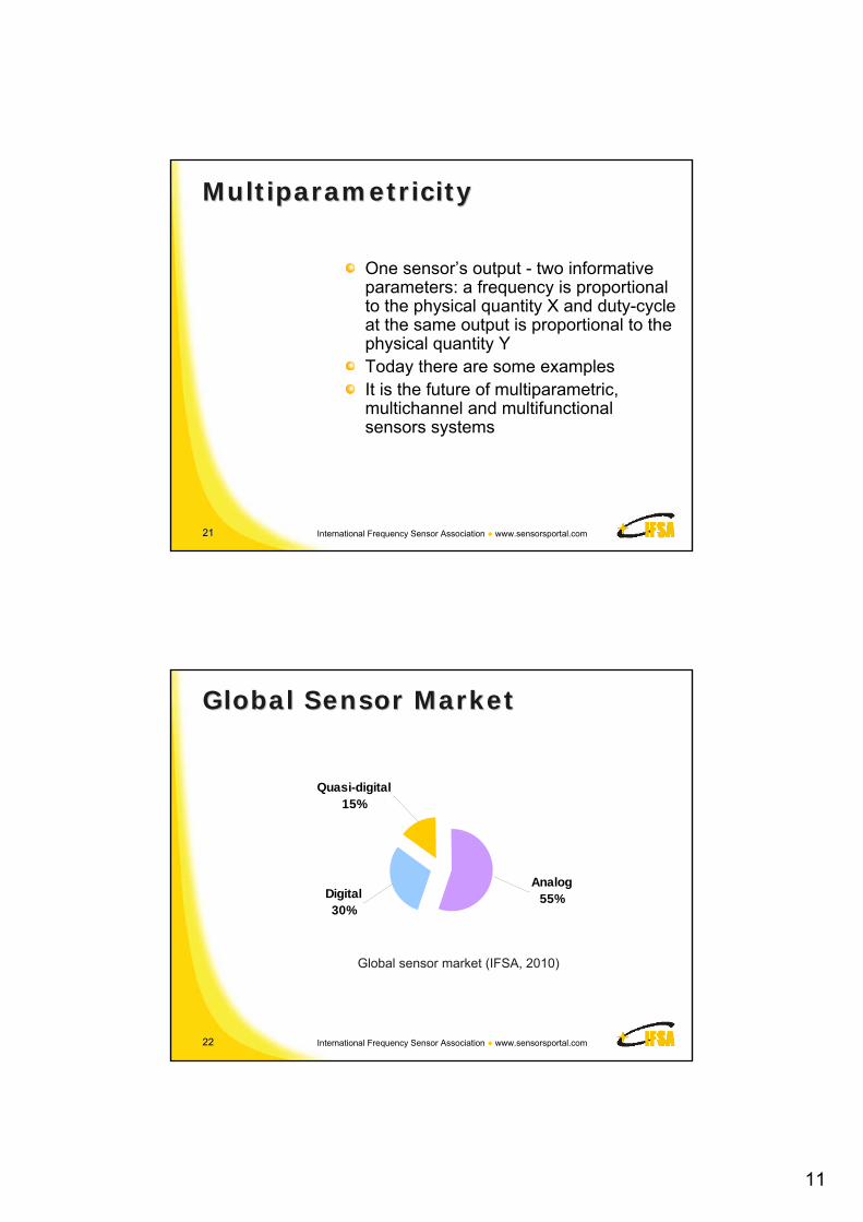
Global Sensor MarketGlobal Sensor Market
Analog55%Digital
30%
Quasi-digital15%
Global sensor market (IFSA, 2010)

12
2323 International Frequency Sensor Association ● www.sensorsportal.com
QuasiQuasi--Digital SensorsDigital Sensors
Frequency70%
PWM16%
Duty-cycle9%
Phase-shift1%
Period1%Pulse Number
3%
Classification of quasi-digital sensors in term of output signal (IFSA, 2010)
2424 International Frequency Sensor Association ● www.sensorsportal.com
Historical FactsHistorical Facts
19301930 - string distant thermometer (Pat. No.61727, USSR, Davydenkov N., Yakutovich M.)19311931 - string distant tensometer(Pat. No. 21525, USSR, Golovachov D., Davydenkov N., Yakutovich M.)19411941 - ADC for the narrow time intervals (Pat. No. 68785, USSR, Filipov V.N. and Negnevitskiy S.B.

13
2525 International Frequency Sensor Association ● www.sensorsportal.com
Frequency Output SensorsFrequency Output Sensors
In 1961 professor P.V. Novitskiy wrote: "... In the future we can expect, that a class of frequency sensors will get such development, that the number of now known frequency sensors will exceed the number of now known amplitude sensors..."
Although there are frequency output sensors practically for any physical, chemical, electrical and non-electrical variables, this prognosis has not been fully justified.
2626 International Frequency Sensor Association ● www.sensorsportal.com
Some Subjective ReasonsSome Subjective Reasons
Lacking awareness of the innovation potential of modern frequency-to-digital conversion methodsMajor expenditures were invested into development of traditional expensive ADCsLack of emphasis being placed on the business and market benefits which such measuring technologies can bring to companies

14
2727 International Frequency Sensor Association ● www.sensorsportal.com
Some Objective ReasonsSome Objective Reasons
Advanced frequency-to-digital conversion methods are patented
Difficulties in software development for microcontroller based frequency-to-digital controller
2828 International Frequency Sensor Association ● www.sensorsportal.com
Universal FrequencyUniversal Frequency--toto--Digital Digital Converter (UFDCConverter (UFDC--1)1)
Low cost digital IC with programmable accuracy
2 channels, 16 measuring modes for different frequency-time parameters and one generating mode (fosc/2 = 8 MHz)
Based on four patented novel conversion methods
Should be very competitive to ADC and has wide applications
15
2929 International Frequency Sensor Association ● www.sensorsportal.com
FeaturesFeatures
Frequency range from 0.05 Hz up to 7 MHz without prescaling and 112 MHz with prescalingProgrammable accuracy (relative error) for frequency (period) conversion from 1 up to 0.001 %Relative quantization error is constant in all specified frequency range Non-redundant conversion timeQuartz-accurate automated calibrationRS-232/485, SPI and I2C interfaces
3030 International Frequency Sensor Association ● www.sensorsportal.com
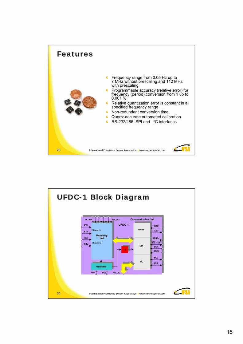
UFDCUFDC--1 Block Diagram1 Block Diagram
16
3131 International Frequency Sensor Association ● www.sensorsportal.com
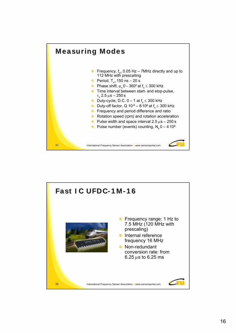
Measuring ModesMeasuring Modes
Frequency, fx1 0.05 Hz – 7MHz directly and up to 112 MHz with prescallingPeriod, Tx1 150 ns – 20 sPhase shift, x 0 - 3600 at fx 300 kHzTime interval between start- and stop-pulse, x 2.5 s – 250 sDuty-cycle, D.C. 0 – 1 at fx 300 kHz Duty-off factor, Q 10-8 – 8.106 at fx 300 kHz Frequency and period difference and ratioRotation speed (rpm) and rotation accelerationPulse width and space interval 2.5 s – 250 sPulse number (events) counting, Nx 0 – 4.109
3232 International Frequency Sensor Association ● www.sensorsportal.com
Fast IC UFDCFast IC UFDC--1M1M--1616
Frequency range: 1 Hz to 7.5 MHz (120 MHz with prescaling)Internal reference frequency 16 MHzNon-redundant conversion rate: from 6.25 s to 6.25 ms
17
3333 International Frequency Sensor Association ● www.sensorsportal.com
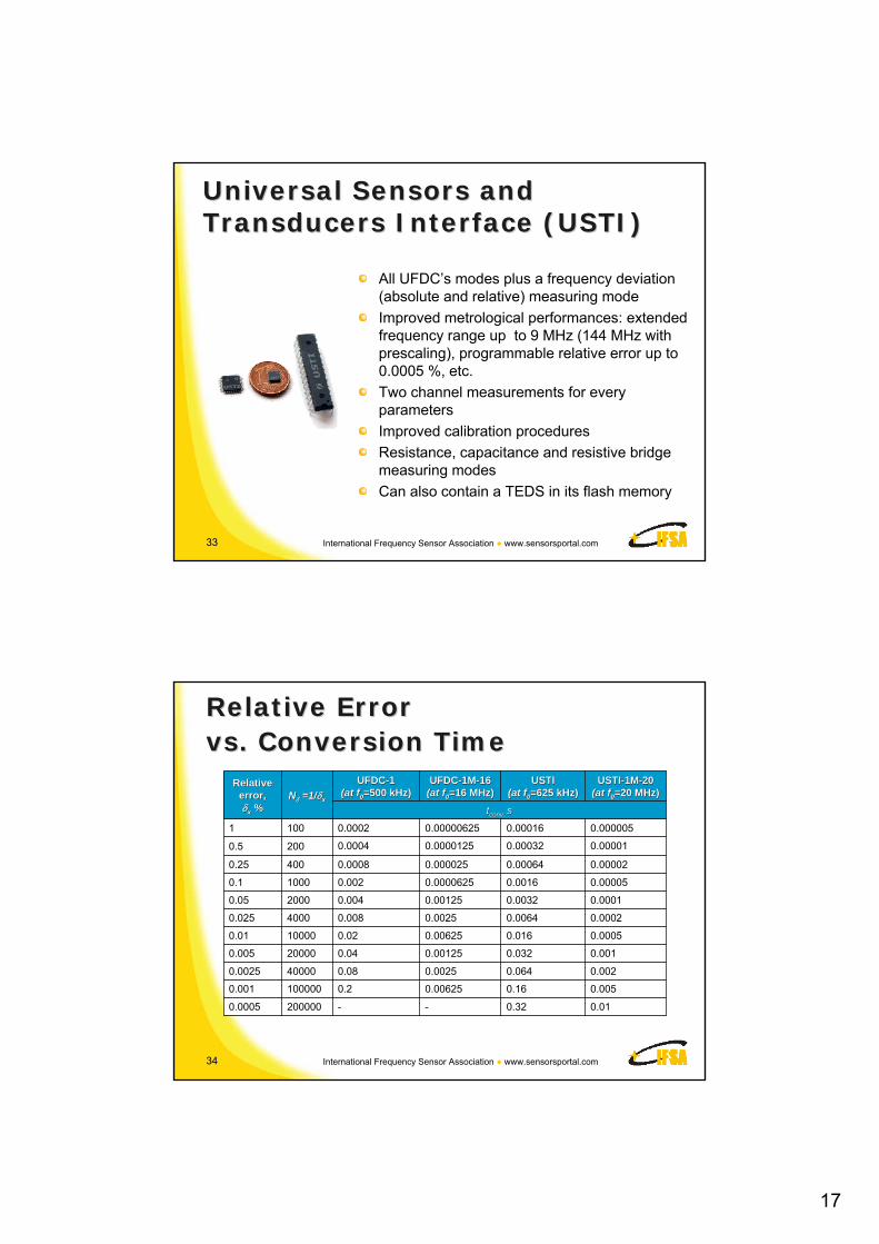
Universal Sensors and Universal Sensors and Transducers Interface (USTI)Transducers Interface (USTI)
All UFDC’s modes plus a frequency deviation (absolute and relative) measuring mode
Improved metrological performances: extended frequency range up to 9 MHz (144 MHz with prescaling), programmable relative error up to 0.0005 %, etc.
Two channel measurements for every parameters
Improved calibration procedures
Resistance, capacitance and resistive bridge measuring modes
Can also contain a TEDS in its flash memory
3434 International Frequency Sensor Association ● www.sensorsportal.com
Relative Error Relative Error vs. Conversion Timevs. Conversion Time
0.010.32--2000000.0005
0.0050.160.006250.21000000.001
0.0020.0640.00250.08400000.0025
0.0010.0320.001250.04200000.005
0.00050.0160.006250.02100000.01
0.00020.00640.00250.00840000.025
0.00010.00320.001250.00420000.05
0.000050.00160.00006250.00210000.1
0.000020.000640.0000250.00084000.25
0.000010.000320.00001250.00042000.5
0.0000050.000160.000006250.00021001
ttconvconv, , ss
USTIUSTI--1M1M--2020(at f(at f00=20 MHz)=20 MHz)
USTIUSTI(at f(at f00=625 kHz)=625 kHz)
UFDCUFDC--1M1M--1616(at f(at f00=16 MHz)=16 MHz)
UFDCUFDC--11(at f(at f00=500 kHz)=500 kHz)NN =1/=1/xx
Relative Relative error, error, xx %%

18
3535 International Frequency Sensor Association ● www.sensorsportal.com
Conversion Times Conversion Times vs. Relative Errorvs. Relative Error
0
0,05
0,1
0,15
0,2
0,25
0,3
0,35
0,0005 0,001 0,0025 0,005 0,01 0,025 0,05 0,1 0,25 0,5 1
Relative error, %
t, sUFDC-1
UFDC-1M-16
USTI, UFDC-2
USTI - 1M-20
3636 International Frequency Sensor Association ● www.sensorsportal.com
Smart Sensor Systems Smart Sensor Systems Integration: New ChallengesIntegration: New Challenges
Introduction Modern Technologies Smart Sensors Design ADC vs. FDC SoC and SiP Conclusions

19
3737 International Frequency Sensor Association ● www.sensorsportal.com
Digital SensorsDigital Sensors
Number of physical phenomenon, on the basis of which direct conversion sensors with digital outputs can be designed, is essentially limited
Angular-position encoders and cantilever-based accelerometers – examples of digital sensors of direct conversion
There are not any nature phenomenon with discrete performances changing under pressure, temperature, etc.
3838 International Frequency Sensor Association ● www.sensorsportal.com
AngularAngular--Position EncoderPosition Encoder

20
3939 International Frequency Sensor Association ● www.sensorsportal.com
Digital AccelerometerDigital Accelerometer
Toshihiro Itoh, Takeshi Kobayashi, Hironao Okada, A Digital Output Piezoelectric Accelerometer for Ultra-low Power Wireless Sensor Node, in Proceedings of IEEE Sensors 2008, 26-29 October 2008, Lecce, Italy, pp.542-545.
4040 International Frequency Sensor Association ● www.sensorsportal.com
Smart Sensor Example I Smart Sensor Example I
ADC – based digital light sensor ISL29015 (Intersil)
Integration time of 16-bit ADC: 45 … 90 ms
21
4141 International Frequency Sensor Association ● www.sensorsportal.com
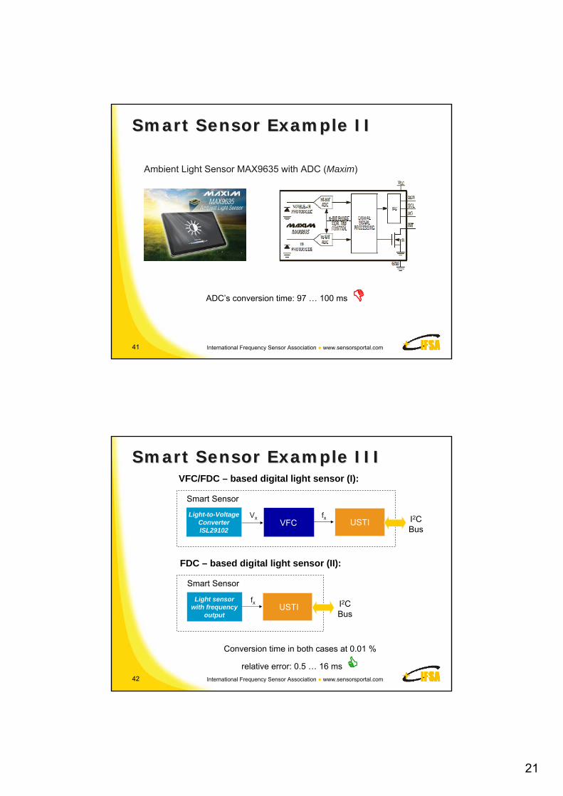
Smart Sensor Example II Smart Sensor Example II
Ambient Light Sensor MAX9635 with ADC (Maxim)
ADC’s conversion time: 97 … 100 ms
4242 International Frequency Sensor Association ● www.sensorsportal.com
Smart Sensor Example III Smart Sensor Example III
Conversion time in both cases at 0.01 %
relative error: 0.5 … 16 ms
VFC/FDC – based digital light sensor (I):
Light-to-Voltage Converter ISL29102
VxVFC
fxUSTI I2C
Bus
Smart Sensor
Light sensor with frequency
outputVFC
fxUSTI I2C
Bus
Smart Sensor
FDC – based digital light sensor (II):

22
4343 International Frequency Sensor Association ● www.sensorsportal.com
VFC Advantages in ADC VFC Advantages in ADC Conversion SchemeConversion Scheme
Monotonicity is inherent under all supply and temperature conditionsAnalog circuitry (the VFC and analog signal conditioning circuits) to be located close to the signal sourceDigital circuitry (frequency-to-digital converter) to be located elsewhereResolution can be increased almost indefinitely
4444 International Frequency Sensor Association ● www.sensorsportal.com
Modern Modern VFCsVFCs
There are a lot of commercially available types of integrated VFCs to meet many requirements (0.012 % integral nonlinearity)Ultra-high speed 1 Hz-100 MHz VFC with 0.06 % linearityFast response (3 s) 1 Hz-2.5 MHz VFC with 0.05 % linearityHigh stability quartz stabilized 10 kHz – 100 kHz VFC with 0.005 % linearityUltra-linear 100 kHz – 1 MHz VFC with linearity inside 7 ppm 0.0007%) and 1 ppm resolution for 17-bit accuracy applicationsUltra-linear 100 kHz – 1 MHz VFC with linearity inside 7 ppm 0.0007%) and 1 ppm resolution for 17-bit accuracy applications

23
4545 International Frequency Sensor Association ● www.sensorsportal.com
A/D Converter TypesA/D Converter Types
HighNone4-8 bitsVery Fast
(1 MHz to 500 MHz)
Flash
LowHigh16 bits or more
Slow to Medium
(Up to 1 MHz or higher)
Sigma-Delta
LowExcellent16-24 bits or more
Medium
(160 kHz to 1 MHz)
VFC-based
LowGood12-24 bitsSlow
(10 Hz to 30 Hz)
Integrating
LowLittle6-16 bitsMedium
(10 kHz to 1 MHz)
Successive Approximation
Relative Cost
Noise Immunity
ResolutionMax SpeedType
4646 International Frequency Sensor Association ● www.sensorsportal.com
SoCSoC and and SiPSiP
Introduction Modern Technologies Smart Sensors Design ADC vs. FDC SoC and SiP Conclusions

24
4747 International Frequency Sensor Association ● www.sensorsportal.com
SystemSystem--onon--Chip (Chip (SoCSoC))
DigitalOutput
SensingElement 1
SensingElement 2
SensingElement 3
VFC
UFDC or USTI
(Core)
TEDS
Sensors and sensing elements
4848 International Frequency Sensor Association ● www.sensorsportal.com
System-in-Package (SiP)
fo
fx1
MEMS Oscillator
Universal Frequency-to-Digital Converter
fx2
MEMS Sensor 1
MEMS Sensor 2
BusOutput
SiP
Sensors system does not require any external time or frequency references
UFDC lets solve problems with the interface circuit design and additional circuitry for MEMS oscillators in order to increase its short frequency stability

25
4949 International Frequency Sensor Association ● www.sensorsportal.com
ConclusionsConclusions
Smart sensors and systems should be intelligent
The ability of intelligent sensors systems to process information is not enough
Efficient coupling this ability with decision making based on data processing in order to learn and adapt will be required
In order to overcame technological limitations we should move from traditional analog signal domain to frequency signal domain, and implement as much system components as possible in digital or quasi-digital domain
Namely by this way we will be able to go ahead: from MEMS devices to MEMS-based systems
5050 International Frequency Sensor Association ● www.sensorsportal.com
Questions & AnswersQuestions & Answers