Embed Size (px)
Citation preview
Smart Timer Dimming
Software Operating Manual
Smart Timer Dimming Software Operating Manual
1.Starting up................................................................................................................... 1
1
11
2
2
9
9
9
10
11
11
11
12
13
3
3
4
4
6
7
7
8
2.User Interface..............................................................................................................
3 General operation ........................................................................................................
A.Appendix: Adaptive Dimming Profile Principle .........................................................
1.1 ...................................................About Smart Timer Dimming Software Operating Manual
1.2 Prerequisites .............................................................................................................
2.1 ..............................................................................................................Basic layout
3.1 ....................................................................................................Download to device
3.2 .........................................................................................Upload device setting to PC
3.3 .......................................................................Open setting file and download to device
A.1 .................................................................................................................................................Principle
A.1.1 ....................................................................Adaptive proportion profile method
A.1.2 .............................................................................Midpoint-set Profile method
A.1.3 ......................................................................................Fixed Profile method
2.2 .................................................................................................................Overview
2.3 ................................................................................Adjustable maximum output (AOC)
2.4 .........................................................................................Constant light output (CLO)
2.5 .........................................................................................................Dimming profile
2.6 ...................................................................................................................Override
2.7 .................................................................................................................Fade time
2.8 Life time .............................................................................................................. .....
2.9 ......................................................................................Dimming Profile DEMO
1.Starting up
Smart Timer Dimming Software Operating Manual
The Smart Timer Dimming Software is utilized for programming LED driver from M W equipped with the Smart Dim feature. TheEAN ELL
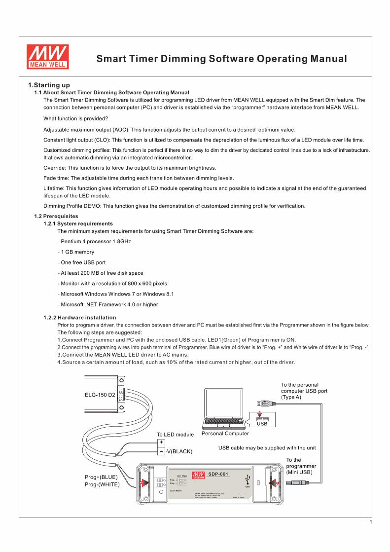
Prior to program a driver, the connection between driver and PC must be established first via the Programmer shown in the figure below.
The following steps are suggested:
1.Connect rogrammer and PC with the enclosed USB cable. LED1(Green) of Program mer is ON.P
2.Connect the programing wires into push terminal of Programmer. Blue wire of driver is to “Prog. +” and White wire of driver is to “Prog. -”.
3.Connect the LED driver to AC mains.M WEAN ELL
4. , % , .Source a certain amount of load such as 10 of the rated current or higher out of the driver
connection between personal computer PC) and driver is established via the “programmer” hardware interface from M W .( EAN ELL
What function is provided?
Adjustable maximum output (AOC): This function adjusts the output current to a desired optimum value.
Constant light output (CLO): This function is utilized to compensate the depreciation of the luminous flux of a LED module over life time.
Customized dimming profiles: This function is perfect if there is no way to dim the driver by dedicated control lines due to a lack of infrastructure.
It allows automatic dimming via an integrated microcontroller.
Override: This function is to force the output to its maximum brightness.
Fade time: The adjustable time during each transition between dimming levels.
Lifetime: This function gives information of LED module operating hours and possible to indicate a signal at the end of the guaranteed
lifespan of the LED module.
Dimming Profile DEMO: This function gives the demonstration of customized dimming profile for verification.
1 2 1. . System requirements
The minimum system requirements for using Smart Timer Dimming Software are:
1.2 Prerequisites
1.1 About Smart Timer Dimming Software Operating Manual
1 2 2. . Hardware installation
- Pentium 4 processor 1.8GHz
- 1 GB memory
- One free USB port
- At least 200 MB of free disk space
- Monitor with a resolution of 800 x 600 pixels
- Microsoft Windows Windows 7 or Windows 8.1
- Microsoft .NET Framework 4.0 or higher
USB
To the personal
computer USB port
(Type A)
Personal Computer
USB cable may be supplied with the unit
To the
programmer
(Mini USB)
ELG-150 D2
+
- -V(BLACK)
Prog-(WHITE)
Prog+(BLUE)
To LED module
1
LED1: Power
CN1 PROG
Prog. +
Prog. -
USB
��������������� � ��������������� ����������������������� ���,
�!"���#!���� $��%�&'����"�� M CHINAADE IN
SDP-001
2
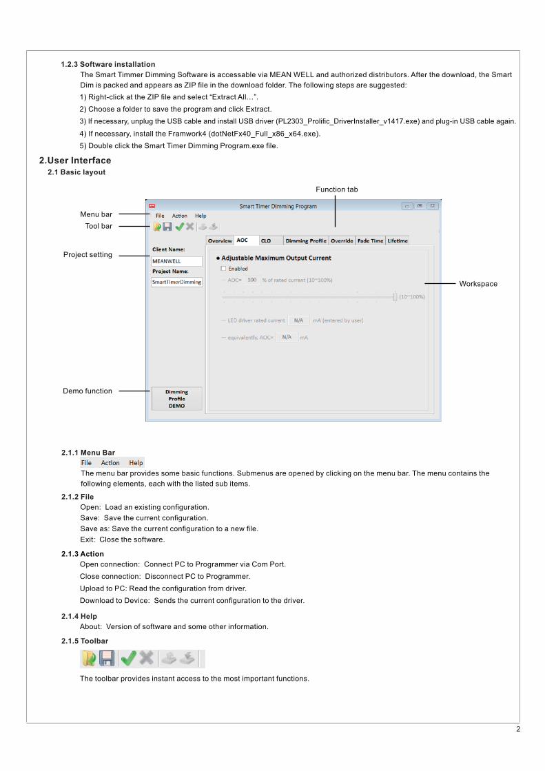
The Smart Timmer Dimming Software is accessable via M W and authorized distributors. After the download, the SmartEAN ELL
Dim is packed and appears as ZIP file in the download folder. The following steps are suggested:
1.2.3 Software installation
2.1 Basic layout
2 1 1. . Menu Bar
2.1.2 File
2 1 3. . Action
2.1.4 Help
2 1 5. . Toolbar
1) Right-click at the ZIP �le and select “Extract All…”.
2) Choose a folder to save the program and click Extract.
3) If necessary, unplug the USB cable and install USB driver (PL2303_Proli�c_DriverInstaller_v1417.exe) and plug-in USB cable again.
4) If necessary, install the Framwork4 (dotNetFx40_Full_x86_x64.exe).
5) Double click the Smart Timer Dimming Program.exe �le.
2.User Interface
Menu bar
Tool bar
Project setting
Demo function
Function tab
Workspace
The menu bar provides some basic functions. Submenus are opened by clicking on the menu bar. The menu contains the
following elements, each with the listed sub items.
Open: Load an existing con�guration.
Save: Save the current con�guration.
Save as: Save the current con�guration to a new �le.
Exit: Close the software.
Open connection: Connect PC to Programmer via Com Port.
About: Version of software and some other information.
The toolbar provides instant access to the most important functions.
Close connection: Disconnect PC to Programmer.
Upload to PC: Read the con�guration from driver.
Download to Device: Sends the current con�guration to the driver.
3
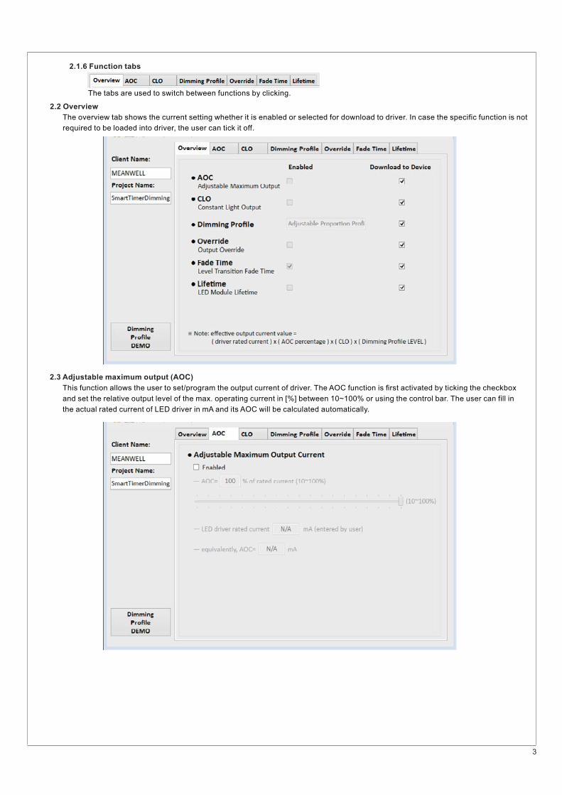
The tabs are used to switch between functions by clicking.
The overview tab shows the current setting whether it is enabled or selected for download to driver. In case the specific function is not
required to be loaded into driver, the user .can tick it off
2.1.6 Function tabs
2 2. Overview
2 3. Adjustable maximum output (AOC)
This function allows the user to set/program the output current of driver. The AOC function is �rst activated by ticking the checkbox
and set the relative output level of the max. operating current in [%] between 10~100% or using the control bar. The user can fill in
the actual rated current of LED driver in mA and its AOC will be calculated automatically.
4
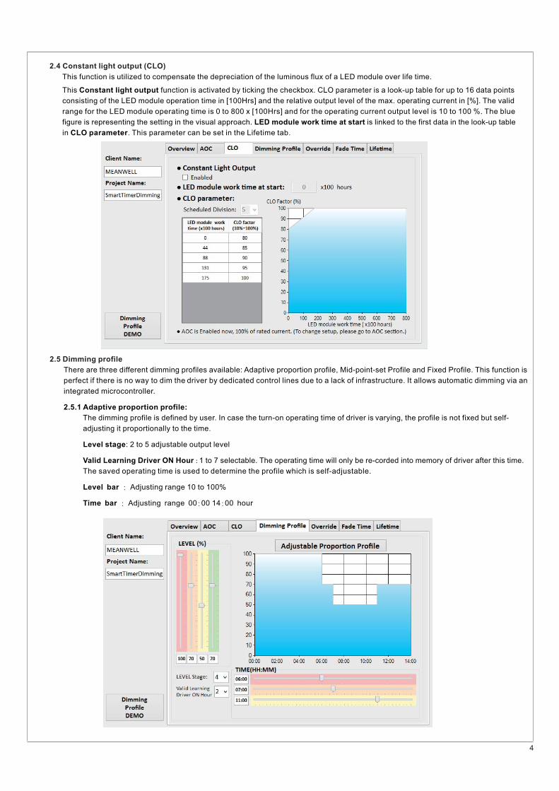
There are three different dimming profiles available: Adaptive proportion profile, Mid-point-set Profile and Fixed Profile. This function is
perfect if there is no way to dim the driver by dedicated control lines due to a lack of infrastructure. It allows automatic dimming via an
integrated microcontroller.
2.5.1 Adaptive proportion profile:
The dimming profile is defined by user. In case the turn-on operating time of driver is varying, the profile is not fixed but self-
adjusting it proportionally to the time.
Level stage: 2 to 5 adjustable output level
Valid Learning Driver ON Hour -: 1 to 7 selectable. The operating time will only be re corded into memory of driver after this time.
The saved operating time is used to determine the profile which is self-adjustable.
Level bar : Adjusting range 10 to 100%
Time bar : : :Adjusting range 00 00 14 00 hour
2 5. Dimming profile
2 4. Constant light output (CLO)
This function is utilized to compensate the depreciation of the luminous flux of a LED module over life time.
This is a look-up table for up to 16 data pointsConstant light output function is activated by ticking the checkbox. CLO parameter
consisting of the LED module operation time in [100Hrs] and the relative output level of the max. operating current in [%]. The valid
range for the LED module operating time is 0 to 800 x [100Hrs] and for the operating current output level is 10 to 100 %. The blue
figure is representing the setting in the visual approach. is linked to the first data in the look-up tableLED module work time at start
in . This parameter can be set in the Lifetime tab.CLO parameter
5
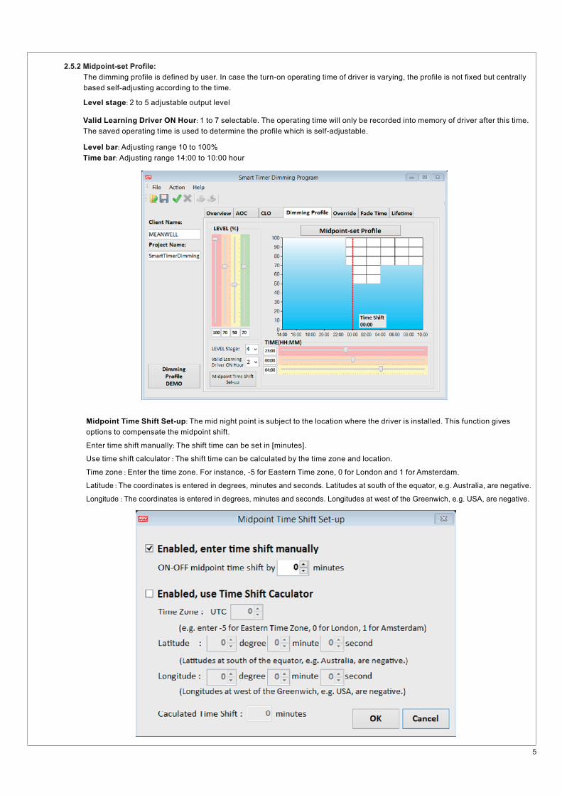
Midpoint Time Shift Set-up: The mid night point is subject to the location where the driver is installed. This function gives
Enter time shift manually The shift time can be set in [minutes].:
Use time shift calculator The shift time can be calculated by the time zone and location.:
Time zone Enter the time zone. For instance, -5 for Eastern Time zone, 0 for London and 1 for Amsterdam.:
Latitude The coordinates is entered in degrees, minutes and seconds. Latitudes at south of the equator, e.g. Australia, are negative.:
Longitude The coordinates is entered in degrees, minutes and seconds. Longitudes at west of the Greenwich, e.g. USA, are negative.:
options to compensate the midpoint shift.
2.5 2. Midpoint-set Profile:
The dimming profile is defined by user. In case the turn-on operating time of driver is varying, the profile is not fixed but centrally
based self-adjusting according to the time.
Level stage: 2 to 5 adjustable output level
Valid Learning Driver ON Hour: 1 to 7 selectable. The operating time will only be recorded into memory of driver after this time.
The saved operating time is used to determine the profile which is self-adjustable.
Level bar: Adjusting range 10 to 100%
Time bar: Adjusting range 14:00 to 10:00 hour
6
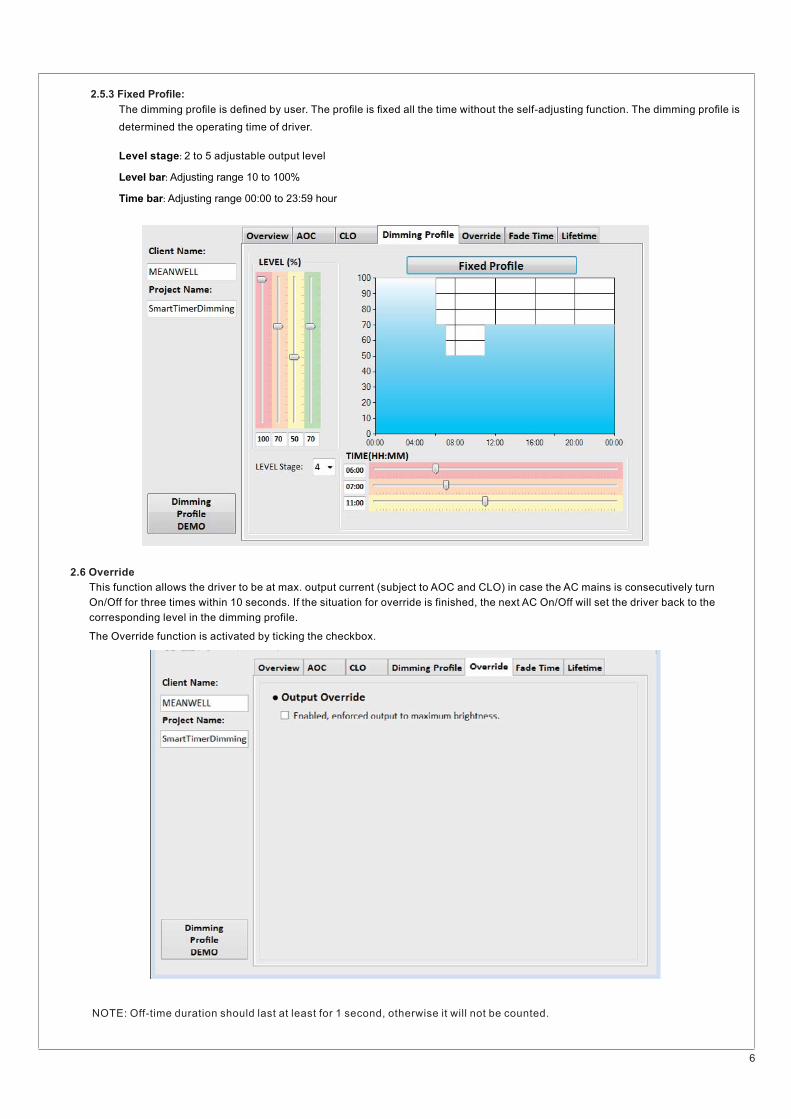
The dimming pro�le is de�ned by user. The pro�le is �xed all the time without the self-adjusting function. The dimming pro�le is
determined the operating time of driver.
Level stage: 2 to 5 adjustable output level
Level bar: Adjusting range 10 to 100%
Time bar: Adjusting range 00:00 to 23:59 hour
2 5 3. . Fixed Pro�le:
This function allows the driver to be at max. output current (subject to AOC and CLO) in case the AC mains is consecutively turn
On/Off for three times within 10 seconds. If the situation for override is finished, the next AC On/Off will set the driver back to the
corresponding level in the dimming profile.
The Override function is activated by ticking the checkbox.
NOTE: Off-time duration should last at least for 1 second, otherwise it will not be counted.
2 6. Override
7
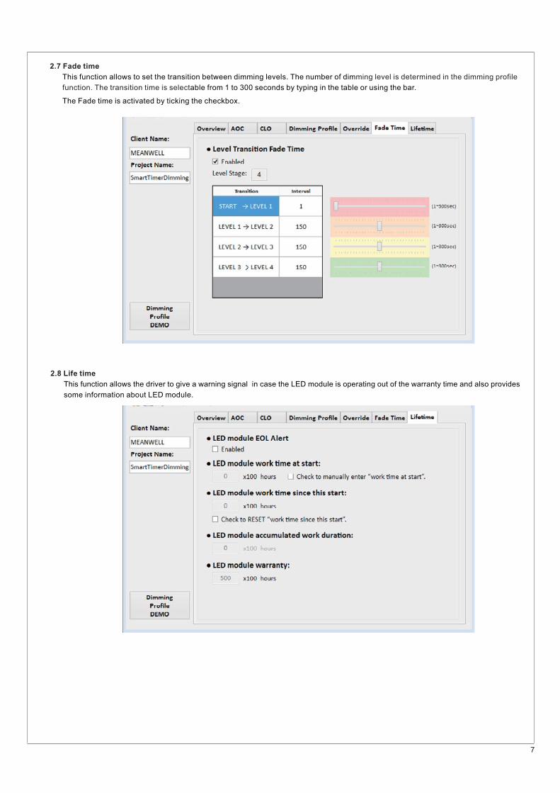
This function allows to set the transition between dimming levels. The number of dimming level is determined in the dimming profile
function. The transition time is selectable from 1 to 300 seconds by typing in the table or using the bar.
The Fade time is activated by ticking the checkbox.
2 7. Fade time
This function allows the driver to give a warning signal in case the LED module is operating out of the warranty time and also provides
some information about LED module.
2.8 Life time
8
LED module EOL Alert: The end of life (EOL) function allows the driver to give a warning signal by �ashing for 3 times at the
beginning of turn-on in case the LED module is operating out of the warranty time meaning LED module accumulated work
duration LED module warranty> .
The EOL function is activated by ticking the checkbox.
LED module work time at start: This parameter is set at zero by default and linked to the �rst data in the look-up table in CLO
parameter. If needed, the value can be manually entered after the checkbox is enabled. It indicates how long LED module has
worked before working with present driver.
LED module work time since this start: This parameter is automatically counted in 100Hrs] during operation of driver. If needed,[
the number can be rest by the checkbox. It indicates how long LED module has worked with present driver.
LED module accumulated wtime at start: LED module work +This parameter is equal to .LED module work time since this start
EOL is executed in case LED module accumulated work duration > LED module warranty.
LED module warranty: LED module EOL AlertThis parameter can be set in case checkbox is enabled.
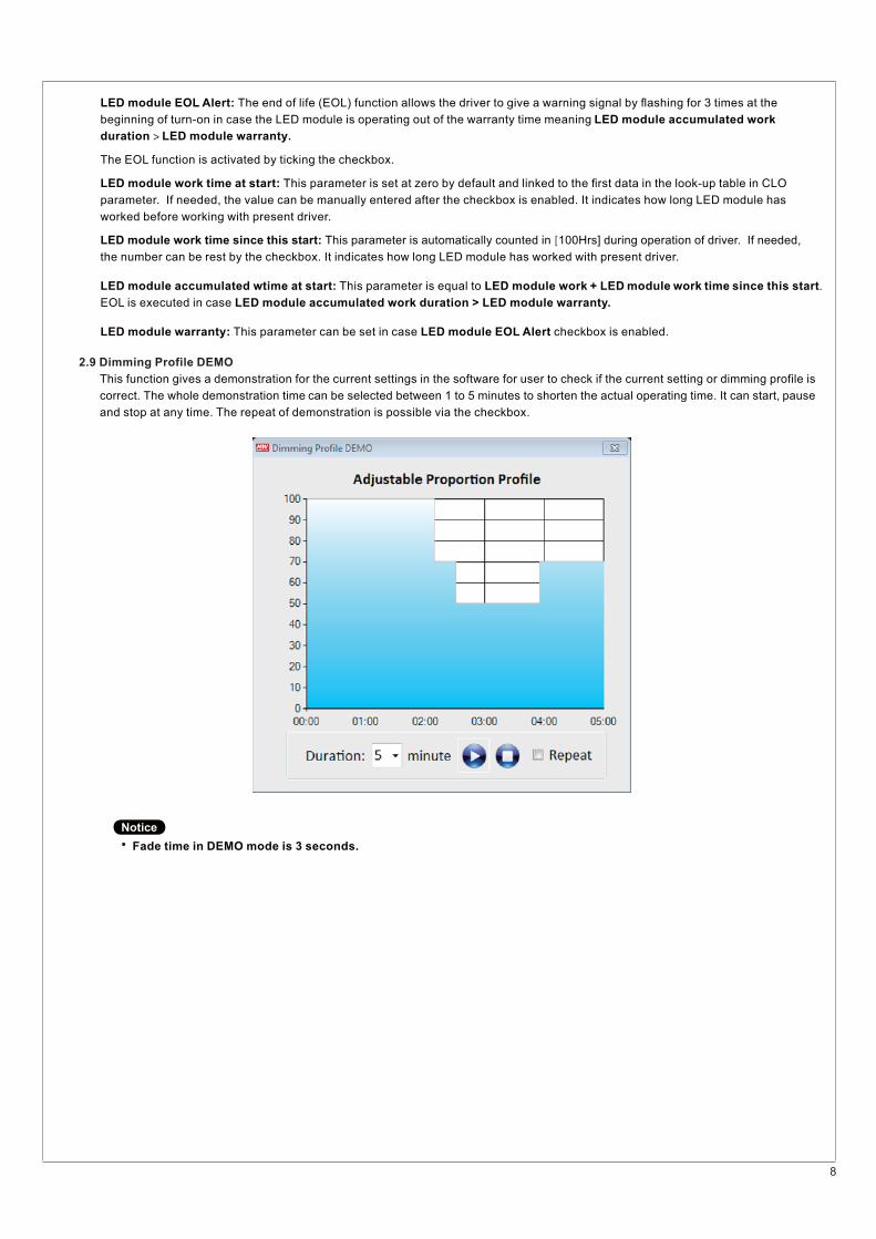
2 9. Dimming Profile DEMO
This function gives a demonstration for the current settings in the software for user to check if the current setting or dimming profile is
correct. The whole demonstration time can be selected between 1 to 5 minutes to shorten the actual operating time. It can start, pause
and stop at any time. The repeat of demonstration is possible via the checkbox.
�Fade time in DEMO mode is 3 seconds.
Notice
9
3.General operation
3.1 Download to device
3.2 Upload device setting to PC
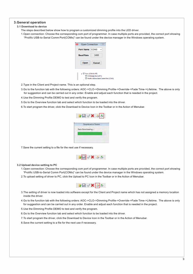
The steps described below show how to program a customized dimming profile into the LED driver.
1.Open connection: Choose the corresponding com port of programmer. In case multiple ports are provided, the correct port showing
2.To upload setting of driver to PC, click the Upload to PC Icon in the Toolbar or in the Action of Menubar.
3.The setting of driver is now loaded into software except for the Client and Project name which has not assigned a memory location
4.Go to the function tab with the following orders: AOC->CLO->Dimming Profile->Override->Fade Time->Lifetime. The above is only
5.Use the Dimming Profile DEMO to test and verify the program.
6.Go to the Overview function tab and select which function to be loaded into the driver.
7.To start program the driver, click the Download to Device Icon in the Toolbar or in the Action of Menubar.
8.Save the current setting to a file for the next use if necessary.
“Prolific USB-to-Serial Comm Port(COMx)” can be found under the device manager in the Windows operating system.
inside the driver.
for suggestion and can be carried out in any order. Enable and adjust each function that is needed in the project.
1.Open connection: Choose the corresponding com port of programmer. In case multiple ports are provided, the correct port showing
3.Go to the function tab with the following orders: AOC->CLO->Dimming Profile->Override->Fade Time->Lifetime. The above is only
4.Use the Dimming Profile DEMO to test and verify the program.
5.Go to the Overview function tab and select which function to be loaded into the driver.
6.To start program the driver, click the Download to Device Icon in the Toolbar or in the Action of Menubar.
7.Save the current setting to a file for the next use if necessary.
2.Type in the Client and Project name. This is an optional step.
“Prolific USB-to-Serial Comm Port(COMx)” can be found under the device manager in the Windows operating system.
for suggestion and can be carried out in any order. Enable and adjust each function that is needed in the project.

10
3.Go to the function tab with the following orders: AOC->CLO->Dimming Profile->Override->Fade Time->Lifetime. The above is only
4.Use the Dimming Profile DEMO to test and verify the program.
5.Go to the Overview function tab and select which function to be loaded into the driver.
6.To start program the driver, click the Download to Device Icon in the Toolbar or in the Action of Menubar.
7.Save the current setting to same file or a new file for the next use if necessary.
for suggestion and can be carried out in any order. Enable and adjust each function that is needed in the project.
3.3 Open setting file and download to device
1.Open connection: Choose the corresponding com port of programmer. In case multiple ports are provided, the correct port showing
2.Using the Open Icon in the Toolbar or in the File of Menu bar to load the setting from a file.
“Prolific USB-to-Serial Comm Port(COMx)” can be found under the device manager in the Windows operating system.
11
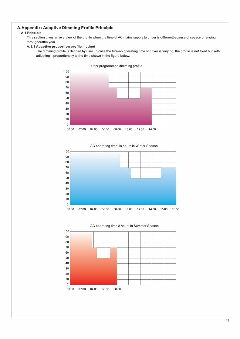
A.Appendix: Adaptive Dimming Profile Principle
A.1 Principle
A.1.1 Adaptive proportion profile method
This section gives an overview of the profile when the time of AC mains supply to driver is differentbecause of season changing
The dimming profile is defined by user. In case the turn-on operating time of driver is varying, the profile is not fixed but self-
adjusting it proportionally to the time shown in the figure below.
throughoutthe year.
100
90
80
70
60
50
40
30
20
10
0
00:00 02:00 04:00 06:00 08:00 10:00 12:00 14:00 16:00 18:00
100
90
80
70
60
50
40
30
20
10
0
00:00 02:00 04:00 06:00 08:00 10:00 12:00 14:00
100
90
80
70
60
50
40
30
20
10
0
00:00 02:00 04:00 06:00 08:00
User programmed dimming profile
AC operating time 18 hours in Winter Season
AC operating time 8 hours in Summer Season
12
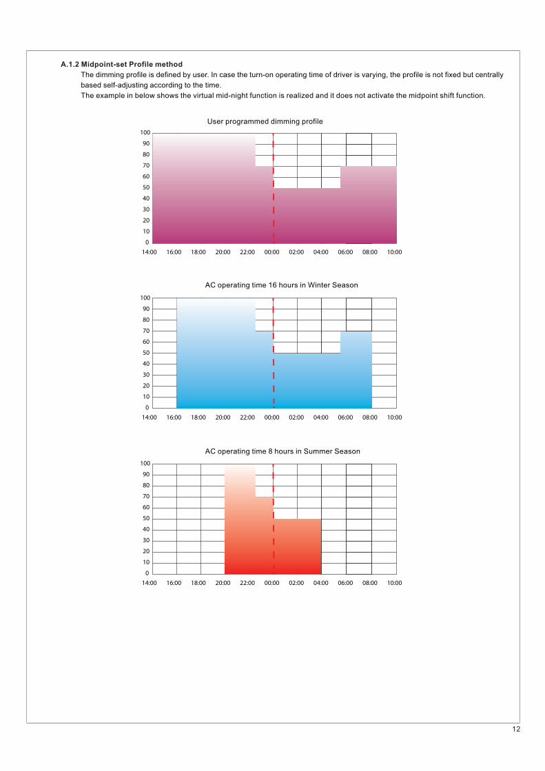
A.1.2 Midpoint-set Profile method
The dimming profile is defined by user. In case the turn-on operating time of driver is varying, the profile is not fixed but centrally
based self-adjusting according to the time.
The example in below shows the virtual mid-night function is realized and it does not activate the midpoint shift function.
100
90
80
70
60
50
40
30
20
10
0
00:00 02:00 04:00 06:00 08:00 10:0014:00 16:00 18:00 20:00 22:00
100
90
80
70
60
50
40
30
20
10
0
00:00 02:00 04:00 06:00 08:00 10:0014:00 16:00 18:00 20:00 22:00
100
90
80
70
60
50
40
30
20
10
0
00:00 02:00 04:00 06:00 08:00 10:0014:00 16:00 18:00 20:00 22:00
User programmed dimming profile
AC operating time 16 hours in Winter Season
AC operating time 8 hours in Summer Season
13
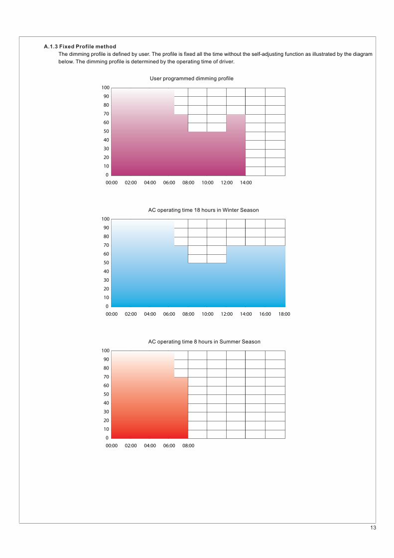
A.1.3 Fixed Profile method
The dimming profile is defined by user. The profile is fixed all the time without the self-adjusting function as illustrated by the diagram
below. The dimming profile is determined by the operating time of driver.
100
90
80
70
60
50
40
30
20
10
0
00:00 02:00 04:00 06:00 08:00 10:00 12:00 14:00 16:00 18:00
100
90
80
70
60
50
40
30
20
10
0
00:00 02:00 04:00 06:00 08:00 10:00 12:00 14:00
100
90
80
70
60
50
40
30
20
10
0
00:00 02:00 04:00 06:00 08:00
User programmed dimming profile
AC operating time 18 hours in Winter Season
AC operating time 8 hours in Summer Season


![INDEX [meanwell.com]meanwell.com/Upload/PDF/meanwell_LED.pdf · APC-8, APC-12, APC-16, APC-25, APC-35 3 APV-8E, APV-12E, APV-16E 4 APC-8E, APC-12E, APC-16E LP ... Over voltage protection](https://img.pdfslide.net/doc/110x75/5b619e107f8b9a40488c919f/index-apc-8-apc-12-apc-16-apc-25-apc-35-3-apv-8e-apv-12e-apv-16e-4.jpg)


![tmm/talks/bord04.2/bord2.6up.pdf · [ VisDB Windows group dimensions separate dimensions relevance factor dim. 3 dim. 1 dim. 4 dim. 2 dim. 5 dimensi ... wvvw.research.att.com/—rab/trellis/sunspot.html]](https://img.pdfslide.net/doc/110x75/5aabf4807f8b9a8d678c7324/tmmtalksbord042bord26uppdf-visdb-windows-group-dimensions-separate-dimensions.jpg)