Embed Size (px)
Citation preview
9250149.FM rev. 3
SmartBobInventory Management System
Software ManualVersion 2
Operating InstructionsPlease read carefully

9250149.FM rev. 3
System Requirements
The Windows Inventory Management System software requires the following hardware:
IBM compatible Personal Computer, 80486 DX2 66MHz or higher
SVGA Graphics Card and Monitor 800 x 600 min. resolution
1 Serial communications port
16MB RAM (Random Access Memory) on Win 95/98
32MB RAM (Random Access Memory) on Win NT
Windows 95, 98, NT version 4.0 (service pack 4 or higher), 2000
RS-485 Interface Module (supplied by BinMaster)
RS-232 Serial Cable (supplied by user)
SmartBob Remote Units

9250149.FM rev. 3
Installing the Software
Insert the BinMaster IMS CD into the cd drive. From Control Panel select Add/Remove Programs and then select “Install”. Select the cd rom drive where the IMS cd is located. Run the setup.exe file. The software will start to automatically load. The program will automatically select the C:\Program Files\Garner Industries\BinMaster V2.x.x as the location where the program will be stored. This path appears in abbre-viated form as C:\...\BinMaster V2.x.x on the screen. Following the program location, the default location where the program will store its measurement Data is C:\Program Files\Garner Industries\BinMaster\ V2.x.x\Data. This also appears in abbreviated form on the screen. If you are not intending to share the data file or put the data file out on a network server for sharing, then this C drive location for the data file is proper.
If you are going to share your data with other computers by allowing them to map to your drive, you may want to put the data files on a drive other than your C: drive. In this case you would enter your desired location path in place of the default path. If you want to share the data from a network server drive, then that location path should be entered as the place where the data is to be stored. You must type in the path to the location you want the data in place of the default location. For example, if your server drive is K:\, then you could type in K:\Data, or a more extended path if desired. You must put the word Data at the end of your path so that the program will create a Data folder.
If the IMS software is only going to be running on one PC there will be no file sharing or remote access by other PC’s then jump to Initial Startup. If there is going to be file sharing or remote access, then continue reading the next paragraph.
Sharing the Data and System Files
If you place the Data in a directory that is not your C:\ drive, you will need to enter that drive location into the BDE. This is a manual operation done after you finished loading the IMS program. It is accomplished as follows:
1. Go to the Control Panel menu and select the BDE icon. 2. There will be two tabs in the program window, “Databases” and “Configurations”, select the ‘Data-
bases” tab. Now select “SmartBob223”. Click on “PATH”, a radio button will now appear at the far right end. Push the radio button and a window labeled “Select Directory” will open. Change the directory in this window to the same directory you put in for the data folder during installation of the IMS software. This is the directory drive you will be sharing with other viewers. On some computers you may only need to put in the Drive letter or name. On other computers you may need to enter the complete path to the “\Data” folder. If you cannot edit the “PATH” parameter, select the SmartBob223 icon in the left pane, right-click and choose “Close” to close the current connection and allow maintenance to the “PATH” parameter. Then you can change the “PATH” parameter. After the “PATH” has been changed, push the OK button to close this window. Then in the next window push YES to save the change.
3. Now select the “Configurations” tab, expand the configuration tree, and two more tabs will be shown, “Drivers” and “System”.
4. Expand the “Drivers” and then expand the “Native” tab under it. Several more items will be under “Native”.
5. Click on the “Paradox” item, several things will be displayed in the right hand pane.6. Click on the “NET DIR” line, a radio button will now appear at the far right end. Push the radio button
and a window labeled “Select Directory” will open. Change the directory in this window to the same directory drive you put in for the data folder during installation of the IMS software. This is the direc-tory drive you will be sharing with other viewers. You should only put in the Drive letter or name, not the entire path. Then push the OK button to close this window. Then in the next window push YES to save the change.

9250149.FM rev. 3
Each PC that is to share the data must have the IMS software loaded on it and its BDE NET DIR set to the location of the data file. If the data directory is on a network server, then the directories set into the BDE on each PC will be that of the network server. If a network drive is not being used, but other PCs are being mapped to a host PC directory, then the drive on each PC which is mapped to the host PC directory must be entered in that PCs NET DIR. As the IMS software is being loaded on each of these PCs, when the installation program asks for the location of the Data, the appropriate path to the server location or other mapped drive location must be entered.
Each PC that is sharing the data files, but not actually controlling the Smart Bob remote units, must be set No Interface”. This is accomplished in the IMS program by going into the Setup and then Options menu in the IMS program. Put a check mark in the No Interface box.
When creating your bin System File in the IMS software, you must store the System in the same directory where the “Data” folder resides. This will either be the specified directory on the host computer or the net-work server. Do not store the System File in the Data folder, but in the directory with the Data folder. PCs sharing a System and Data will go to that directory to select and open the System.
Remote Access Setup
When setting up Remote Access, each PC must enter, in the IMS software, the port setting which corre-sponds to the location of its modem. In the IMS program, enter the “Setup” and then “Options” menu to enter the modem port. All remote PCs, which will be calling into the host PC, need to have the host tele-phone number entered. Enter the “Setup” and then “IMS Settings” menu, activate the Remote button and enter the Remote (host PC) phone number. A radio button will appear in the IMS tool bar to allow activa-tion of dial out.
Each remote site must enter a System name in their IMS program identical to the name of the host System you want to access. This done in the same way you normally enter a System name. Select “File” and “New System” to activate the window for adding a system name. You will not place any tanks in the Sys-tem, as these will be copied from the host PC automatically when you access its system file.
When remote accessing system data, first, from the File, Open System menu, select and open the desired System on your local PC. Then, go into the Setup, IMS Settings menu and type in the exact name of the System you want to access in the System Name space.
To set up the host PC for Remote access, start the Remote IMS program by clicking on its icon which appears below the BinMaster IMS icon in your program list. A window will appear labeled Remote IMS Server. You must enter the tank System(s) which others will be permitted to view. To do this, click on Setup in the window, and then on the System Files button which appears. This will open another window labeled IMS Access List. Click on the Add button, this will open another window labeled Select Accessi-ble Files. Select the system file you want and then click on the Open button. That window will close and the file path will now appear in the IMS Access List, click on the Done button to close this window, or on the Add button if more System files are to be added.
The Remote IMS program must remain running on the host PC in order for outside users to be able to call in and access the information. You can minimize the Remote IMS program window. While the Remote IMS program is running, it has control of the modem on the port designated in the IMS program. Other programs that may be running on the PC cannot access this particular modem. The IMS program itself has priority, and in the event of an alarm condition, will pre-empt the Remote Access program and take control of the modem to dial out if it is set up to do so.
If you have any questions, please contact BinMaster at 1-800-278-4241.

9250149.FM rev. 3
Initial Startup
Start the BinMaster IMS program. On the initial startup of the program, you will be asked to enter your reg-istration number. Enter your registration number and then click on the OK button.
IMPORTANT! Do not just press the enter key or the activation code will not get set and the IMS program will just go into the demo mode and measurements will not be allowed to be taken.
After entering your registration number and clicking the OK button the IMS program will come up. A sys-tem will need to be configured. Proceed on to Quick Setup.Quick Setup
Here is a simple step by step guide to quickly configure and begin using your SmartBob Inventory Man-agement System (IMS) software. To get started, set the SmartBob IMS options, Create a new IMS system file, and begin adding bins to your IMS system.
Follow the steps below to set the minimum options to run your SmartBob Inventory Management System.
1. Select Options from the Setup menu.
2. Configure the Port Settings and Units.
3. Select New System from the File menu.
4. Configure the General System Information and set the Local interface option then save the system file.
5. Add your bins and configure the Bin Setup for each new bin. See Adding Bins for more information.
6. Test the measurement operation of each new bin by performing a Manual Measurement.
7. This completes the setup of the basic operating features. You can now setup the Autoscan options and the Faxing, Paging, and E-mailing notification features.
Opening an IMS System File
To open a IMS system file or create a new file. Select Open System or New System from the File menu or use the New or Open toolbar buttons. You will be prompted with a file dialog. Enter or browse for the IMS file name to open and select OK. The system file will opened and the bins will be displayed on the main window.
When creating a new system file the IMS Settings window will be opened. Adjust the system settings and press the OK button when you are finished. You will then be prompted for a file name to store the settings in. Enter a file name to select OK. The new bin databases will be created and the system will be opened. You are now ready to start adding bins to the system. See Adding and Removing bins for more informa-tion.
Adding and Removing Bins
Bins can be added or removed from a system at any time. To add a bin select Add Bin from the Setup menu. When adding a bin the Bin Setup window will open. Set the Bin Number to select which of the main window tabs the bin will be displayed on.

9250149.FM rev. 3
To remove a bin, highlight the bin to be removed by left clicking on it. Then select Remove Bin from the Setup menu. Or right mouse click on the bin to be removed and select Remove Bin from the popup menu. Select Yes when prompted to remove the bin. CAUTION!! measurement data from a removed bin will be lost.
Taking Measurements
Measurements can be initiated in two ways. Measurements can be done with Autoscanning or a single bin can be measured. To select a bin and take a measurement, highlight the bin by left clicking on it and then select Measure Bin from the Action menu or click the measure tool button. The Measure Dialog will be dis-played. Press the start button to start a measurement.
To start an Autoscan measurement select Start Autoscan from the Action menu or press the Autoscan tool button. Press the Yes button when you are prompted to start an autoscan. See IMS Settings for more information on autoscan operation.
Manual Measurements
The manual measurement dialog, allows you to take an immediate level measurement for a single bin. The measurement window can simply start a manual measurement or can be used to take several mea-surements with a repeated delay. To access the measurement dialog, select Measure Bin from the Action menu or use the Measure tool button. Each measurement is displayed on the dialog as it is taken.
Repeat IntervalSet the repeat interval to take multiple unattended measurements of a bin. The repeat interval can be set to take a single measurement or can be set with intervals to measure continuously or repeated up to 240 minutes apart. When repeated measurements are being done, the Stop button will be enabled to stop measuring.

9250149.FM rev. 3
Select BobUse the option if you want to restrict measuring to a single SmartBob unit if the bin has multiple SmartBob units assigned to it.
Level History
The BinMaster IMS software records every measurement taken by a SmartBob unit. These measure-ments are sorted by pins and the bob numbers. The Level History for a bin can be displayed by selecting Level History from the View menu, clicking the Level History toolbar button or by right-clicking on a bin and selecting Level History from the pop menu. The Level History displays a trend graph of the bins level and displays a point for every measurement. A more detailed listing of the measurements is shown under the graphs in a table.
Zooming the GraphThe graph allows you to zoom into an area to display more detail of measurements over a short time period. To zoom into an area, place the mouse pointer over the upper left of the area you would like to zoom into. While holding down the left mouse button, drag the mouse to the lower right of the area to be zoomed. A zoom box will be displayed around the area. Release the mouse button and the area inside the zoom box will be enlarged. To restore the graph to a normal view, press the restore button on the Level History window.
Panning the GraphThe graph also allows panning. To pan left or right through the graph. Place the mouse pointer on the graph, and while holding the right mouse button, drag the pointer left or right. To restore the graph to a normal view, press the restore button on the Level History window.
Deleting MeasurementsTo delete measurements, press the Delete button on the Level History window. You will be prompted to enter a date. Measurements older than the date entered will be deleted from the measurement database.
Printing Level HistoryThe level history may be printed by pressing the print button. A print preview window will be displayed to allow you to preview the report, change printer setups and begin printing.
NOTE: If the graph zoom has been used the printed graph will match the zoomed view.
Inventory
The inventory of all your bins can be displayed on a single graph and table. To display the bin inventory, select Inventory from the View menu or click the Inventory toolbar button. The inventory graph will display the bin levels as percentages so the levels can be compared to each other. More detail may be found in the Inventory table.

9250149.FM rev. 3
Printing the InventoryTo print the bin inventory, press the Print button on the Inventory window. A print preview window will be displayed to allow you to preview the report, change printer setups and begin printing.
Port Settings
The Port Settings tab of the configuration window allows you to set the serial communication ports the soft-ware will use to communicate with the SmartBob units. You can also set the communication port your modem is attached to, if the faxing and paging options will be utilized. The Port Settings can be accessed by selecting Options from the Setup menu.
No InterfaceCheck this box if the IMS system program being used does not have a SmartBob interface connected and the program is only being used to access remote IMS data or data across a network.
Interface 1 and Interface 2These options are used to set the communication serial ports to be used by the program for operating the SmartBob.
Expanded CheckboxCheck this box if an expanded interface is being used. An expanded interface allows up to 90 SmartBobs to operate on one system. The main window tabs will expand to display the expanded Bobs when the expanded checkbox is checked.
Remote NotificationSet this option to the communications port used by your modem. The IMS software can then be used to page or fax information when level warnings occur or report an operation failure of a SmartBob.

9250149.FM rev. 3
Units
The units tab of the configurations window allows you to set the measurement units for configuration and level indication of all the bins. The Units setting can be accessed by selecting Options from the Setup menu.
DimensionalThis option sets the dimension units for setting of the height, width/diameter, and length of each bin. This setting also controls the units the content height will be displayed in.
WeightThis option sets the units the weight of the bin contents will be displayed in.
Volume This option sets the units the volume of the bin contents will be displayed in.
DensityThis option sets the weight per cubic unit that the density value can be entered in. This value must be set for the BinMaster IMS software to correctly calculate the weight of the bin contents.

9250149.FM rev. 3
Passwords
The passwords tab of the configuration window allows you to set a password which can then be used to protect un-authorized access to the Configurations, Bin Settings, the System File settings and protect against accidental deletion of measurement history. The Passwords tab can be accessed by selecting Options from the Setup menu.
PasswordThis is the password that will be used to protect the Configurations, Bin Settings, System File settings and protect against accidental deletion of measurement history. The password can be up to 10 alphanumeric digits and is case sensitive.
Bin SettingsCheck this box to protect the Bin Settings from un-authorized access.
IMS SettingsCheck this box to protect the IMS file settings from being changed by an un-authorized user.
Measurement HistoryCheck this box to protect the Measurement history from accidental deletion.

9250149.FM rev. 3
User Information
The User Information tab of the configurations window allows you to set the information that will be sent with faxes and e-mail notifications. The information can be used by the receiver of a fax or e-mail to iden-tify where it originated from. This information is a Federal requirement and must be transmitted with all faxes. The User Information tab can be accessed by selecting Options from the Setup menu.
Company Name, Street Address, City State/ZipEnter this general information so a receiver of your fax will know where the fax originated from.
Voice NumberEnter a voice number that receiver of a SmartBob IMS fax can call.
Fax NumberEnter the number of your fax line that the SmartBob IMS software will be using.
Fax E-Mail HeaderThis memo field is supplied to provide an extra note or information that can be sent with all faxes and e-mails.

9250149.FM rev. 3
The E-Mail tab is used to set your e-mail address, the outgoing mail host address and port information for outgoing e-mail. This information is required for sending e-mail notifications from the IMS software.
E-Mail AddressE-Mail address to use for originating e-mail from the IMS software.
User IDA user ID may be required if your e-mail host uses a proxy server. If the e-mail host does not require a user ID, leave this blank.
Outgoing Mail HostEnter the mail host address into this field. The host must support SMTP mail protocol to use e-mail notifi-cation in the IMS software. If e-mail is already configured on your system this information can usually be found under the account information of your e-mail application.
Server Port NumberThe server port is normally set to 25, but may need to be changed in some instances. This information can also be found under the account information of your e-mail program.
CC: E-MailsOne or more e-mail addresses may be specified to send carbon copies of all e-mails to. If more than one address is to be specified, separate them with a semicolon. Example: “[email protected];[email protected]”

9250149.FM rev. 3
IMS System Files
BinMaster IMS System Files manage the operation of the SmartBob units, storage of bin settings, mea-surement data, and Autoscan setups. Each system file can store data for up to 30 individual bins or SmartBob units. New system files can be created by selecting New from the file menu or by selecting the new system button from the IMS toolbar. A system file must be created or opened before measurement data can be accessed or taken. The last system file opened when the program is exited will be opened when the BinMaster IMS software is started again.
General IMS System Settings
The General tab of the IMS system settings, allow you to enter a system name, a description of the system and assign a interface the system will be accessed through. These settings can be set by selecting IMS Settings from the Setup menu. When a new system is created, you will be prompted to save the new sys-tem file. It is recommended to create a separate file folder for your system files so they can be easily backed up.
System NameEnter a descriptive name for your IMS system. This name will appear on the top border of the program window so the currently opened system file can be identified.
DescriptionThis field can be used to store a description of the system for later reference.
PasswordEnter a password in this field to prevent un-authorized remote access to a system file.
Connection (Local/Remote)Select the type of connection to be used to access control of the SmartBob units that make up the IMS sys-tem. Use a local if the SmartBob units interface is connected directly to the PC using a BinMaster RS232 interface. Choose Remote if the system is to be accessed through another PC running the BinMaster IMS software

9250149.FM rev. 3
Port SettingSelect the RS232 interface to be used to control the SmartBob units for this system. The Interface 1 & Interface 2 serial port settings can be set form the Configurations Port Settings tab.
Remote Phone NumberEnter the phone number of the Remote IMS system to be accessed.
ExpandedCheck this box if the remote system has an expanded interface.
Alarms
The system alarms tab is used to set the action resulting from alarms on any of the SmartBob units in the system. The alarm features range from simply a simple dialog displaying the alarm condition, to audible warnings and faxing, paging, or e-mail notification if desired. The alarms tab can be accessed by selecting IMS Settings from the Setup menu.
Warning DialogCheck this box if you would like a warning dialog to be displayed when a level alarm is reached or when a Bob malfunction occurs.
Audible WarningCheck this box to have an audible “beep” or wave file play when the warning dialog is displayed. The audi-ble warning will sound every 3 seconds until the warning dialog is acknowledged.
Note: If your PC has multi-media capabilities and a sound card, the default Windows sound is played. A wave file must be assigned to the default Windows systems sound for it to play.
Pager System IDThe pager system ID should be set to distinguish the system that caused the alarm to the recipient of the pager message. The ID can be up to 4 digits long.

9250149.FM rev. 3
Fax Pager or E-MailSelect the type of contact. Select FAX if the phone number is to a fax machine or Pager if the number is to a pager. Select e-mail and enter the e-mail address if the contact has e-mail. Select the Advanced button for more options when paging is selected.
Description and Number/E-MailEnter the description and phone number or e-mail of the individual to be contacted when an alarm or error condition occurs.
Page DelaySet the amount of time to delay between dialing the pager phone number and sending the message to the pager. This value may vary between different paging services, so a different delay is provided for each phone number. The page delay does not have any effect on the call progress for a fax. Select the Advanced button for more options when paging.
High, Low, Supply and Error AlarmCheck each box corresponding to the type of alarm condition(s) you wish the contact to be notified about.
Site Status and Notify ScheduleIf the Bin Status option is checked, the contact can be sent an e-mail or fax of the current bin levels of all the bins in the IMS system. Set the interval and start time-of-day that the contact will be sent an update of the site status.

9250149.FM rev. 3
Autoscan
The Autoscan tab of the IMS settings window can be used to configure the bins to be scanned during auto-matic and manual Autoscan operations and to set the time and interval for automatic Autoscans to be com-pleted.
Autoscan EnabledCheck this box to enable automatic Autoscanning of the selected bins. When this box is checked the soft-ware will automatically Autoscan at the preset interval from the starting time.
Autoscan IntervalSet the interval delay between automatic Autoscans. Setting the delay to hour and minute intervals to zero will cause an Autoscan to occur once every 24 hours on the starting time.
Starting TimeSet the starting time to control the time of the first Autoscan for every 24 hour period. This starting time can be used to control the time of an Autoscan that occurs once a day or to control the time past the hour that Autoscans will completed on during a day.
9250149.FM rev. 3
Bin Setups
Bin Setups are entered to configure the size of a bin, density of the bin contents, assign SmartBob addresses, set Alarm heights and control the display of level information for a bin. The bin setups must be entered before measurements can be taken for a bin and are important to allow the program to calculate the correct height, weight, and volume of the bin contents. Bin Setups can be accessed by selecting Bin Settings from the Setup menus or by right-clicking on a bin and selecting Bin Settings from the popup menu.
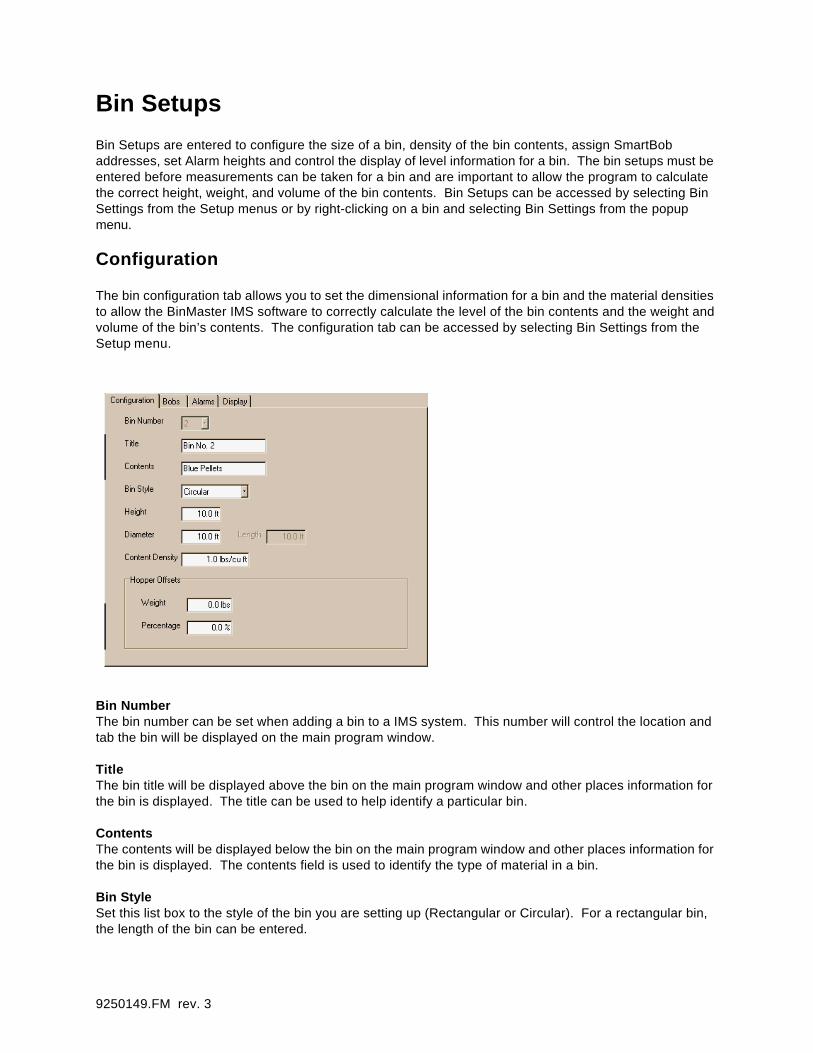
Configuration
The bin configuration tab allows you to set the dimensional information for a bin and the material densities to allow the BinMaster IMS software to correctly calculate the level of the bin contents and the weight and volume of the bin’s contents. The configuration tab can be accessed by selecting Bin Settings from the Setup menu.
Bin NumberThe bin number can be set when adding a bin to a IMS system. This number will control the location and tab the bin will be displayed on the main program window.
TitleThe bin title will be displayed above the bin on the main program window and other places information for the bin is displayed. The title can be used to help identify a particular bin.
ContentsThe contents will be displayed below the bin on the main program window and other places information for the bin is displayed. The contents field is used to identify the type of material in a bin.
Bin StyleSet this list box to the style of the bin you are setting up (Rectangular or Circular). For a rectangular bin, the length of the bin can be entered.

9250149.FM rev. 3
Height, Diameter, and LengthEnter the dimensions of the bin in the units specified in each field. The length parameter can be entered for rectangular bins.
Content DensityEnter the density of the material being stored in the bin. Use the units specified in the field. The content density is used by the BinMaster IMS software to calculate the total weight of the material stored in a bin.
Hopper Offset (Weight or Percentage)The hopper offsets can be set if the bin has a hopper bottom that the SmartBob unit will not be able to measure. Enter either the weight or the total percentage of the bin contents that the hopper will hold of the material in the bin. Changing either value will update the other value automatically. Leave these values at zero if you do not want the bin measurements offset.
Bob Addresses
The Bobs tab allows you to configure which SmartBob units will be controlled each bin. Up to 5 SmartBob units may be tied to a single bin. The Average height for all five SmartBobs is used for calculations of the content level, weight and volume. The Bobs tab can be accessed by selecting Bin Settings from the Setup menu.
Number of BobsSet this value to the number of Bobs that will be controlled for the bin. A bin can have the measurements of 1 t 5 SmartBob units averaged for calculations of the level, weight, and volume. It may be necessary to use more than one Bob if the bin has a large surface area.
Bob Address 1-5The Bob address controls sets the Bobs to be operated during a measurement. This value corresponds to the settings on the SmartBob unit’s address dip switch.

9250149.FM rev. 3
Bin Alarms
The bin alarms tab allows you to set the High and Low alarms levels for each bin and the contact numbers for paging and faxing for alarm conditions for a bin. The Bin Alarms tab can be accessed by selecting Bin Settings from the Setup menu.
High Low and Supply Alarm EnableCheck these boxes to enable the High, Low, or Supply alarms for a bin. The alarm level indicators on the bins will disappear when they are not enabled. When an alarm is enabled its level indicator will be dis-played on the bin detail and can be dragged with the pointer to a new level. Each level indicator has its own color to distinguish it from the others. When an alarm is enabled a warning dialog box can be dis-played and any Alarm Notification faxes and pages will be sent if the alarm level is exceeded. See the IMS Alarms Settings for more information on bin alarms.
High, Low, and Supply Alarm LevelsSet these values to trigger an alarm condition when the content height exceeds the pre-set level. Enter the height value in the units shown in the field. Or drag the corresponding level indicator on the bin detail.
Alarm NotificationFive notification numbers can be setup for each individual bin. These numbers can be set to call on any of the alarm conditions. The settings are entered the same as those for the IMS Alarms. See the IMS Alarm Settings for more information.
Bin StatusA bin status notification can be sent to E-Mail and fax recipients at specified intervals during a 24 hour period. Check the Bin Status option to send a fax or e-mail at specified intervals. When Bin Status is checked the Notify Schedule will be enabled for editing.

9250149.FM rev. 3
Display
The display tab of the Bin Settings allows you to set the color the bin content level is displayed as, and the format the bin’s level value and graduations are displayed in. The display tab can be accessed by select-ing Bin Settings from the Setup menu.
Level IndicationThis setting will change the format that the bins level will be displayed as. The level can be displayed as the content height, weight, volume or percentage full. This setting will also change the format of the grad-uations show in the bin detail of the main window.
Content ColorThis setting controls the color the bin content level is displayed as.
Faxing, Paging, and E-Mail
The BinMaster IMS software has the ability to fax, page, or e-mail personnel or suppliers when a bin’s level reaches a High, Low, or Supply point or when there is a malfunction with a SmartBob unit. Five contacts may be setup for each IMS system and an additional five contacts can be setup for each individual bin. The contacts setup for the entire system are called when an alarm condition occurs for any bin in the sys-tem whereas the contacts setup for each individual bin are called when an alarm condition occurs for that specific bin.
PagingWhen the BinMaster IMS software is paging, a small dialog box will be displayed to show the recipient of the page and the progress of the call. The page message includes three pieces of information.
Pager System ID - - 4 digit number identifying the system with the alarm condition.Alarm Code - - 2 digit number identifying the alarm condition.Bin Number - - 2 digit number identifying the bin with the alarm condition.
Page Message Format: <Pager System ID (4-digits)><Alarm Code (4-digits)><Bin Number (2-digits)>
Sample: “0001-50-21” or “00015021” - - A low level warning for bin number 21

9250149.FM rev. 3
Alarm Codes10 -- A communication error with a SmartBob interface occurred while trying to make a measurement.20 -- A SmartBob unit was not fully retracted when a measurement was started.30 -- A SmartBob unit could not be retracted and may be stuck.50 -- A Low level alarm has occurred for the bin.60 -- A high level alarm has occurred for the bin.
FaxingWhen the BinMaster software is faxing a small dialog box will be displayed to show the recipient of the fax and the progress of the call. The fax messages are text based and pass the general information to identify the recipient and the sender of the fax and information concerning the alarm condition that has occurred and the current level information for the bin contents.
Example:
!!!!!!!!!!!!!!!!!!!!!!!!!!!!!!!!!!!!!!!!!!!!!!!!!!!!!!!!!!!!!!!!!!!!!!!!!!!!!!!!!!!!!!!!!!!!!!!!!!!!!!!!!!!!!!!!!!!!!!!!!!!!!!!!!!!!!!!!!!!!!!!!! !!!! To : Fax Recipient !!!! Fax 555-1234 !!!! !!!! From : Fax Sender !!!! 5555 Street !!!! Somewhere, NE !!!! Ph. 555-123-4567 !!!! Fax 555-321-7654 !!!! !!!!!!!!!!!!!!!!!!!!!!!!!!!!!!!!!!!!!!!!!!!!!!!!!!!!!!!!!!!!!!!!!!!!!!!!!!!!!!!!!!!!!!!!!!!!!!!!!!!!!!!!!!!!!!!!!!!!!!!!!!!!!!!!!!!!!!!!!!!!!!!!!
!!!!!!!!!!!!!!!!!!!!!!!!!!!!!!!!!!!!!!!!!!!!!!!!!!!!!!!!!!!!!!!!!!!!!!!!!!!!!!!!!!!!!!!!!!!!!!!!!!!!!!!!!!!!!!!!!!!!!!!!!!!!!!!!!!!!!!!!!!!!!!!HIGH LEVEL WARNING
!!!!!!!!!!!!!!!!!!!!!!!!!!!!!!!!!!!!!!!!!!!!!!!!!!!!!!!!!!!!!!!!!!!!!!!!!!!!!!!!!!!!!!!!!!!!!!!!!!!!!!!!!!!!!!!!!!!!!!!!!!!!!!!!!!!!!!!!!!!!!!!
Bin Number : 30Bin Name : Bin No. 30Contents : Lime Green PelletsMax Level : 50.0 ft.
Current Level : 47.7 ft.Current Weight : 3,746.3 lbsCurrent Volume : 3,746.3 lbsCurrent Percentage: 95.4%
9250149.FM rev. 3
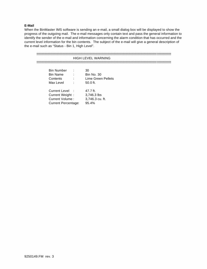
E-MailWhen the BinMaster IMS software is sending an e-mail, a small dialog box will be displayed to show the progress of the outgoing mail. The e-mail messages only contain text and pass the general information to identify the sender of the e-mail and information concerning the alarm condition that has occurred and the current level information for the bin contents. The subject of the e-mail will give a general description of the e-mail such as “Status - Bin 1, High Level”.
!!!!!!!!!!!!!!!!!!!!!!!!!!!!!!!!!!!!!!!!!!!!!!!!!!!!!!!!!!!!!!!!!!!!!!!!!!!!!!!!!!!!!!!!!!!!!!!!!!!!!!!!!!!!!!!!!!!!!!!!!!!!!!!!!!!!!!!!!!!!!!!HIGH LEVEL WARNING
!!!!!!!!!!!!!!!!!!!!!!!!!!!!!!!!!!!!!!!!!!!!!!!!!!!!!!!!!!!!!!!!!!!!!!!!!!!!!!!!!!!!!!!!!!!!!!!!!!!!!!!!!!!!!!!!!!!!!!!!!!!!!!!!!!!!!!!!!!!!!!!
Bin Number : 30Bin Name : Bin No. 30Contents : Lime Green PelletsMax Level : 50.0 ft.
Current Level : 47.7 ft.Current Weight : 3,746.3 lbsCurrent Volume : 3,746.3 cu. ft.Current Percentage: 95.4%

9250149.FM rev. 3
Advanced Paging Options
The advanced paging dialog allows you to set extra parameters for paging if necessary. To access the Advanced Paging window, press the advanced button when editing the pager number.
Dial after connectThis field allows you to enter digits to be dialed after the pager phone number is dialed and the pager delay has expired. This may be necessary if the pager service is automated and other options must be selected on the service before the message is sent.
Dial after messageThis field can be used to enter digits that must be inserted into the page message. This may be necessary if the pager service before the message is sent.
Use Dash/SpaceCheck this box to enable dashes or spaces to be inserted into the page message. Some pagers and pager services support this feature normally by pressing the asterisks on a phone keypad. Use this feature if the pager supports it to make the pager message easier to read.
Dash/Space DigitEnter the digit to be dialed to insert a space or dash in the page message.

9250149.FM rev. 3
Remote System Access
The remote system access features of the BinMaster IMS software allows you to access inventory informa-tion from a remote location. The BinMaster IMS software can perform a quick download of current inven-tory from a remote location and allow offline processing of that information in the form of reports or by viewing on screen. Remote access requires a modem and the Remote IMS Server program to be running on the remote system to be accessed. The Remote IMS Server program is provided as a utility with the BinMaster IMS software. Information is contained in the following sections showing how a remote system may be setup.
Remote IMS Server
The remote IMS Server software must be utilized to allow remote access to IMS systems on a computer. This software controls the modem in your PC and answers incoming calls from a remote system request-ing the IMS data, The software allows access to IMS systems on the host PC and transmits data to the remote system which requests it. If remote access is required at all times, it is recommended that the Remote IMS Server shortcut be placed in your startup folder so it will be running every time the your PC is turned on.
SetupStart the BinMaster IMS software and set the port settings on the options dialog for the modem port to the correct setting. The Remote IMS Server program shares this setting with the BinMaster IMS software.
Next, start the Remote IMS Server program and select the setup menu. A dialog will be displayed to allow additions and deletions of IMS systems that will be accessed by a remote PC. Press the Add button to dis-play a file dialog and add the systems to be accessed. Note: System files end with the file extension “.ims”. Press the done button when the additions or deletions are complete. The Remote IMS Server pro-gram is now ready to accept calls.
On the Pc system that will be remotely accessing the IMS data, create a new system file and set the con-nection type to “remote” along with setting the phone number of the remote PC. Set the name of the sys-tem to the same name as the IMS system to be accessed. Accessed to a system will not be allowed if the names do not match. The password may also be entered at this time if you wish to have the password ver-ified automatically every time a connection to the remote system is made. Otherwise, the password will be prompted for when the connection is made.

9250149.FM rev. 3
ConnectingWhen an IMS system is created with a “remote” connection type, an additional button will be displayed on the toolbar to start the remote connection. Press the button to start the automatic update of inventory infor-mation. The modem will call the remote PC and download the current level information and setups for each bin and update the level history for each bin. When the download is complete the modem will discon-nect from the remote system. Inventory information downloaded can be accessed when the call is com-plete. The last downloaded information will remain available anytime the system file is opened.
Bob Diagnostics
The Bob diagnostics dialog can be used to retract a SmartBob unit’s Bob in the event of a stuck Bob or for testing of a SmartBob unit. To access the Bob diagnostic function, select Bob Diagnostics from the action menu or click the Bob Diagnostics tool button. After the diagnostics dialog is displayed, select the Bob number to be retracted and press the Retract button. The status of the Bob will show “Retracted” if the retract command is successful. Otherwise, an error dialog will display the error that occurred.

9250149.FM rev. 3
Exporting
The measurement data recorded by the BinMaster IMS program can be exported for use in a spreadsheet or other programs. To export the measurement data, select Export from the File menu. When an export is performed, the data for all of the bins will be exported to the same file sorted by the bin number.
File Format:
Measurement NumberBin NumberBob NumberContent Height with unitContent Weight with unitContent Volume with unitContent PercentageDate and Time of Measurement (Day, Month, Date, Time, Year0
Field Separator
There are three format types available, Comma Separated Values (*.csv), Tab Separated (*.txt) and Space Separated (*.txt). The default value is a Comma Separated Value format (*.csv) which can be directly imported into most spreadsheet programs. Select the type of field separator you require for export to another program.
Filename
Type in the name of the file you would like export the data to. Or use the browse button to move to find a directory. and enter the filename.
Customer ServiceBinMaster offers a toll-free Customer Service phone number 1-800-278-4241. You may call the Customer Service Department for technical and assistance Monday through Friday from 8:00 AM to 5:00 PM Central Time. International customers can call us at (402) 434-9102 or reach us via fax at (402) 434-9133.
IMPORTANT-READ CAREFULLY BEFORE OPENING BINMASTER IMS SOFTWARE PACKAGE

9250149.FM rev. 3
The following License Agreement for one licensed copy applies to you. By opening the sealed package(s) containing the software, you indi-cate your acceptance of the following Software License Agreement.
This is a legal agreement between you (either an individual or an entity) and Garner Industries, a Nebraska corporation. By opening the sealed software packages and/or by using the BinMaster Inventory Management Software (IMS) for Windows 95/98/NT Workstation, you agree to be bound by the terms of this Agreement. If you do not agree to the terms of this Agreement, promptly return the disk package and accompanying items (including printed mate-rials and binders or other containers) to the place you obtained them for a full refund.
1. GRANT OF LICENSE -This Software License Agreement (“License”) permits you to use one copy of Garner Industries’ Inventory Management Soft-ware (IMS) for Windows 95/98/NT Workstation and Garner Industries’ associated user documentation (“Software”) on one workstation running Microsoft Windows 95/98/NT Workstation. The Software is "in use” on a computer when it is loaded into the temporary memory (i.e., RAM) or installed into the permanent memory (e.g., hard disk, CR-ROM or other storage device) of that computer, except that a copy installed on a network server for the sole pur-pose of distribution to other computers is not “in use.”
2. COPYRIGHT -The software is owned by Garner Industries and is protected by United States copyright laws and international treaty provisions . Therefore, you must treat the Software like any other copyrighted material (e.g., a book or musical recording) except that you may either (a) make one copy of the Software solely for back up or archival purposes, or (b) transfer the Software to a single hard disk provided you keep the original solely for back up or archival purposes. You may not copy the user documentation provided with the Software, except for your own authorized use.
3. OTHER RESTRICTIONS-This License is your of license to exercise the rights granted herein and must be retained by you. You may not rent or lease the Software, but you may transfer the Software and user documentation on a permanent basis provided you retain no copies and the recipient agrees to the terms of this Agreement. You may not reverse engineer, decompile, or disassemble the Software, except to the extent that the foregoing restric-tion is expressly prohibited by applicable law. If the Software is an update or has been updated, any transfer must include the most recent update and all prior versions.
4. LIMITED WARRANTY-Garner Industries warrants that (a) the Software will perform substantially in accordance with the user documentation for a period of ninety (90) days from the date of receipt. Any implied warranties on the Software are limited to ninety (90) days. Some states/jurisdictions do not allow limitations on duration on an implied, so the above limitation may not apply to you. This limited warranty is void if failure of the Software has resulted from accident, abuse, or misapplication.
5. CUSTOMER REMEDIES -Garner Industries’ and its suppliers’ entire liability and your exclusive remedy shall be, at Garner Industries’ option, either (a) return of the price paid, or (b) replacement of the Software that does not meet Garner Industries’ limited warranty and which is returned to Garner Industries with a copy of your receipt. This limited warranty is void if failure of the Software has resulted from accident, abuse, or misapplication. Any replacement Software will be warranted for the remainder of the original warranty period or thirty (30) days, whichever is longer.
6. NO OTHER WARRANTIES-GARNER INDUSTRIES DOES NOT WARRANT THE FUNCTIONS CONTAINED IN THE SOFTWARE WILL MEET YOUR REQUIREMENTS OR THAT THE OPERATION OF THE SOFTWARE WILL BE UNITERRUPTED OR ERROR FREE. THE ENTIRE RISK AS TO THE QUALITY AND PERFORMANCE OF THE SOFTWARE IS WITH YOU. TO THE MAXIMUM EXTENT PERMITTED BY APPLICABLE LAW, GARNER INDUSTRIES AND ITS SUPPLIERS DISCLAIM ALL OTHER WARRANTIES, EITHER EXPRESSED OR IMPLIED, INCLUDING, BUT NOT LIMITED TO, IMPLIED WARRANTIES OF MERCHANTABILITY AND FITNESS FOR A PARTICULAR PURPOSE, WITH REGARD TO THE SOFT-WARE AND THE ACCOMPANYING WRITTEN MATERIALS. THIS LIMITED WARRANTY GIVES YOU SPECIFIC LEGAL RIGHTS. YOU MAY HAVE OTHERS WHICH VARY FROM STAT/JURISDICTION TO STAT/JURISDICTION.
7. NO LIABILITY FOR CONSEQUENTIAL DAMAGES-TO THE MAXIMUM EXTENT PERMITTED BY APPLICABLE LAW, IN NO EVENT SHALL GARNER INDUSTRIES OR ITS SUPPLIERS BE LIABLE FOR ANY DAMAGES WHATSOEVER (INCLUDING WITHOUT LIMITATION, DAMAGES FOR LOSS OF BUSINESS PROFITS, BUSINESS INTERRUPTION, LOSS OF BUSINESS INFORMATION, OR ANY OTHER PECUNIARY LOSS) ARISING OUT OF THE USE OR INABILITY TO USE THE GARNER INDUSTRIES PRODUCT, EVEN IF GARNER INDUSTRIES HAS BEEN ADVISED OF THE POSSIBILITY OF SUCH DAMAGES. BECAUSE SOME STATES/JURISDICTIONS DO NOT ALLOW THE EXCLUSION OR LIM-ITATION OF LIABILITY FOR CONSEQUENTIAL OR INCIDENTAL DAMAGES, THE ABOVE LIMITATION MAY NOT APPLY TO YOU.
8. U.S. GOVERNMENT RESTRICTED RIGHTS-The Software and documentation are provided with RESTRICTED RIGHTS. Use, duplication, or dis-closure by the Government is subject to restrictions as set froth in subparagraph (c)(1)(ii) of the Rights in Technical Data and Computer Software clause at DFARS 252.227-7013 or subparagraphs (c)(1) and (2) of the Commercial Computer Software-Restricted Rights at 48 CFR 52.227-19, as applicable. Manufacturer is Garner Industries, 4200 North 48th Street, Lincoln, NE 68504-1498.
9. NEBRAKSA LAW-This Agreement is governed by the laws of the State of Nebraska. Should any of the provisions of this License be declared invalid by any court of competent jurisdiction, the balance of the License will remain in full force and effect.
Should you have any questions concerning this Agreement, or if you desire to contact Garner Industries for any reason, please contact:Garner Industries, 4200 North 48 th Street, Lincoln, NE 68504-1498 (402) 434-9100 or 1-800-228-0275
www.binmaster.com