Embed Size (px)
Citation preview

MARCH 16, 2021
by: Paul Fernandes, Vivek Chacko, John Polanski, Gordei Ussatsov and Miha Lotric
SMARTRAWL 2.5 Final Report

University of Aberdeen
Front cover. An image taken in February 2020 in the extension of the trawl being operated by the fishing vessel Sparkling Star during sea trials. The image was taken by a camera mounted in front of the Smartrawl stereo camera system and shows the stereo camera orientation and background netting used to provide improved images.

Smartrawl Phase 2.5 Final Report
3
Executive Summary Smartrawl 2.5 is part of a series of phased projects, to develop a selective device to operate in a demersal trawler allowing for fish to be released in-situ underwater, thus allowing the skipper of the vessel to comply with the landings obligation. This is an interim report for Phase 2.5 of the project, which details work completed so far and highlights the work that is still to be completed. Smartrawl 2.5 was based, largely, on the acquisition of two new major pieces of equipment: i) a new stereo camera; and ii) an underwater modem. Both cameras also required adaptations to work with the modem. The builds of these were delayed due to components not being available from China due to the Coronavirus pandemic. The project, originally due to complete on 31 March 2020, was extended, initially to 31 August 2020, and then to February 2021. Both items were eventually procured: the modem at the end of March and the stereo cameras and their adaptations in the summer. Restrictions on working, travelling and supplies of materials have operated throughout 2020 due to the pandemic, making testing difficult. The modem was tested in the lab and both cameras were tested at sea in December 2020. Another major task was to conduct image analysis and devise computer programs to convert information from the stereo camera to be sent via the modem to the bridge on a fishing vessel. Artificial intelligence computer programs were written which allowed for fish to be detected in the stereo camera images and sized. Integration of the camera, the image analysis (which takes place on a suitable computer) and the modem now require further development. A suitable computer has been bought and it now needs to be integrated into the camera: this will take place during Phase 3.0. Other progress includes: advances in the design of the stereo camera frame; considerations for a new camera housing design; designs of a full-sized gate; three further sea trials; and preparations for obtaining a patent for the Smartrawl system.

University of Aberdeen
Contents Executive Summary ............................................................................................................................. 3
The Smartrawl project ........................................................................................................................ 5
Smartrawl Phase 2.5 objectives ..................................................................................................... 5
1. Objective 1: Stereo camera acquisition ....................................................................................... 6
1.1. Adaptation of existing camera and new camera build ........................................................ 6
1.2. Camera deployment frame .................................................................................................. 6
Box 1. Camera frame deployment protocol ................................................................................... 8
1.3. New housing ....................................................................................................................... 17
2. Software development .............................................................................................................. 17
2.1. Image analysis for fish detection ....................................................................................... 17
2.2. Fish size estimation ............................................................................................................ 19
2.3. File transfer software ......................................................................................................... 20
3. Acoustic modem ........................................................................................................................ 21
3.1. Purchase a suitable underwater acoustic modem (transmitter and receiver) .................. 21
3.2. Modem software ................................................................................................................ 22
4. System tests ............................................................................................................................... 22
4.1. Tests of the modem in a large water tank ......................................................................... 22
4.2. Deployments on a small research vessel (trawler) to test and develop the communication system .......................................................................................................................................... 23
4.3. Deployments on a Scottish mixed demersal fishing trawler operating in the North Sea or west coast of Scotland. ................................................................................................................ 23
5. Additional work ......................................................................................................................... 23
5.1. Building of the full-sized gate ............................................................................................. 23
5.2. Sea trials ............................................................................................................................. 24
5.3. Patent application .............................................................................................................. 24
Annex 1. Material properties ............................................................................................................ 25
Annex 2. Computer code ................................................................................................................. 29
A1.1 Neural Network for fish detection ....................................................................................... 29
Annex 3. Modem message specification ......................................................................................... 33

Smartrawl Phase 2.5 Final Report
5
The Smartrawl project The Smartrawl is a technological development designed to avoid discards and bycatch in demersal fishing trawls, ensuring that only fish and shellfish that are intended to be landed are actually caught at sea. The system consists of a stereo camera with lighting in the trawl extension to obtain high quality images of fish traversing into the cod-end through the trawl net. These images will be analysed by an onboard computer to determine the size and species of the fish. A signal is then sent to a ‘gate’ located in the trawl extension to catch or release the fish: if an unwanted fish is identified, a signal is sent to open the gate and the fish is released back into the wild; if the fish is wanted, a signal is sent to close the gate and the fish passes into the cod end to be captured. This was originally designed to be self-contained without information being passed to the bridge of the vessel. However, an interim modification involves the transfer of information from the stereo camera to the bridge via an underwater communications device (modem). This report describes Phase 2.5 of the project funded under FIS024A. In this initially short phase, the intention was to progress specific components of Smartrawl by adapting and testing a second stereo camera and the underwater modem to transfer data from the camera to the bridge of a trawler. However, the project was seriously affected (delayed) by the pandemic and was unable to complete many of the objectives which involved going out to sea working in the confined spaces of fishing boats.
Smartrawl Phase 2.5 objectives O1 Acquire and adapt a stereo camera for deployment in Scottish demersal fishing trawls.
1.1 Purchase stereo camera as per previous specification. 1.2 Build a deployment frame for incorporation into the trawl extension. 1.3 Build a new housing for the camera system
O2 Write software to detect and size fish on the stereo camera
2.1 Adapt existing image analysis labelling software to detect fish in the images of the stereo camera 2.2 Estimate the size of the fish from labelled images derived from the stereo camera 2.3 Write data transfer software to convert size information to a datafile that can be sent to the modem
O3 Adapt an acoustic modem to transfer data from the camera to the bridge of a trawler
3.1 Purchase and adapt a suitable underwater acoustic modem (transmitter and receiver) 3.2 Write software to convert the number and size of fish being observed on the stereo camera from the modem receiver to a laptop PC on the bridge.
O4 Test the system in the laboratory and during fishing operations.
4.1 Tests in a large water tank. 4.2 Deployments on a small research vessel (trawler) to test and develop the communication system 4.3 Deployments on a Scottish mixed demersal fishing trawler operating in the North Sea or west coast of Scotland.

University of Aberdeen
1. Objective 1: Stereo camera acquisition 1.1. Adaptation of existing camera and new camera build The first task was to secure an adaptation to the existing Smartrawl stereo camera, so that is could be linked to an underwater modem to transfer information from the camera system to the vessel. The link consists of new cabling to transfer information from the onboard computer, which also needed to be adapted and new software written to enable the transfer (see Fig. 1). This was completed and the camera was delivered on the 25 March 2020. The second task consisted of building a new (spare) camera system. This was so that tests could be conducted whilst the other camera was being deployed, and to guard against damage to the existing system preventing further trials. The new camera system was subject to delays of several vital components from China in the light of the pandemic but was eventually delivered in August 2020. Both systems have since been used in earnest at sea (see Section 5.2 below).
1.2. Camera deployment frame
In Smartrawl Phase 2.0, the design analysis and fabrication of the stereo camera frame were carried out using Computer Aided Design (CAD), Finite Element Analysis (FEA) and Computational Fluid Dynamics (CFD). Corrosion resistant materials such as SS316 and HDPE (see page 27-28) were selected for the construction of the frame and the frame was fabricated using TIG welding and CNC milling. Assembly of the frame was carried out with off-the-shelf components with the long-term repairability and reusability in mind. The frame was tested in the large water tank available at the National Decommissioning Centre’s South Building and static balancing was carried out along with the measurement of buoyancy.
Figure 1. Image of the existing stereo camera system returned after modifications (circled in red)

Smartrawl Phase 2.5 Final Report
7
The first version of the stereo camera deployment frame was designed, based on input from the skipper of the trawler, to withstand the rigors of deployment and retrieval while it is attached to the inside of a trawl net. One of the main concerns initially was that the frame would have to pass over a power block during deployment and retrieval of the trawl net. Protocols for deployment were developed for this frame from the sea trials (see Box 1) and in subsequent deployments with a more experienced skipper, this step was circumvented. Based on the observations made during successive deployments in Phases 2.0 and 2.5, the design of the frame was adapted, and design improvements were incorporated into subsequent revisions of the frame design to include the deployment requirements and flow characteristics around the frame. In the intermediate design step during Phase 2.5, the length of the frame was reduced in order to improve handling on the deck (Figure 2). Hoops were introduced into the trawl net at either end of the camera to hold the net open during deployment (Figure 4) so that the there is sufficient space for passage of fish in front of the stereo camera. White netting was also installed along the inner circumference of the trawl extension opposite the stereo camera to provide a contrasting backdrop for acquiring images (lessons learned from Smartrawl 2.0).
Figure 2. New camera frame design: plan view (top), side elevations (middle) and section (bottom) showing the position of the camera (yellow and green).

University of Aberdeen
Box 1. Camera frame deployment protocol
1) Ensure that the camera is fully charged following the procedure outlined in the manual 2) Secure the camera on the frame 3) Check the cable connections to the strobes and power extension cable 4) Open a section of the extension after the square mesh panel near to the cod end 5) Fasten the frame to the fishing net while resting on the quay (Figure 3) 6) The location of the camera frame is based on the net but can be located at any point in the cylindrical section 7) Insert the hoops to hold the net open at two ends of the frame 8) Attach the white netting on the opposite wall of the trawl net facing the camera 9) Close the opening in the trawl net 10) Attach the acoustic transmitter on the outside of the trawl net to the transmitter attachment 11) Use the vessels power block (or crane) to remove the trawl net with the camera attached from the quay to the deck of the boat (Figure 3) 12) The boat then goes out to the trawl ground where the net is deployed 13) The camera is started on the deck of the boat by following the instructions in the operation manual 14) The trawl net with the camera is then deployed 15) After the trawl operation is completed, the trawl net is recovered 16) Once the section with the camera is drawn up, the camera is turned off following the procedure outlined in the manual 17) The equipment is retrieved from the net once the cod end has been emptied 18) Data is downloaded onto the laptop or workstation and the system is switched off
a) b)
Figure 3. a) Inserting the camera frame into the trawl extension. b) the net with the frame being lifted by the vessel’s power block

Smartrawl Phase 2.5 Final Report
9
Figure 4 Modified camera frame and extension rig mounted in the trawl of the Sparkling Star at the quayside prior to departure
Further design modifications including FEA and CFD analyses were carried out to incorporate a new extension to the frame for mounting the modem transmitter. The camera frame was also redesigned to accommodate the transmitter frame. The various steps have been described below beginning with the design of the frame:
1. Design of the frame for the acoustic modem transmitter. A frame is required to mount the transmitter which relays data from the stereo camera to the trawler. The CAD part file for the transmitter was provided by the modem supplier (‘.STEP’ file which was converted to ‘.SLDPRT’). The weight of the transmitter in air and water were measured by using the load cell in the NDC South building (recorded as approximately 14 kg and 6 kg respectively) and this information was used in the structural analysis of the frame.
Computational Fluid Dynamics (CFD) analysis of the transmitter was conducted to determine drag on it. The input and initial conditions used for the simulation are as follows: maximum ambient pressure of approximately 300 MSW, temperature of 8° Celsius, flow velocity of 4 knots or 2.0578 m/s. The fluid considered in the flow analysis was sea water. External flow was considered in the analysis and internal space and cavities without flow conditions were not included in the analysis. The computational domain size was taken as ±0.5775 m x ±0.5775 m x +1.416 m/-0.619m. The results of the analysis are shown in the visualizations below (Figure 5, Figure 6, Figure 7).

University of Aberdeen
Figure 5 Flow around the transmitter shown as semi-transparent arrows. The colour of the arrows represents the flow velocity.
Figure 6 Flow around the transmitter which is shown as a cross-section, and contour and iso-lines for flow velocity.

Smartrawl Phase 2.5 Final Report
11
Figure 7 Flow around the transmitter, and contour and iso-lines for flow velocity.
The maximum drag force on the transmitter frame was computed as 6860.52 N from the CFD analysis and this value is used for the FEA analysis of the transmitter holder frame attachment.
2. Design analysis of the frame for the modem transmitter. The transmitter is required to be located within a maximum of 1 m proximity to the camera because of the connector cable length. The transmitter should also have a clear line of sight with the trawler for communication. The transmitter should also be protected from snagging with debris and the sea floor. The trawl net diameter varies from 1m to 1.5m depending on the trawler. Mounting the transmitter within the trawl net in the proximity of the camera would increase the possibility of both fish and debris impinging on it, besides reducing the cross section of the net and altering the flow pattern in front of the camera which could potentially affect image capture performance.
Based on these considerations, it was concluded that the best location for the transmitter would be outside the trawl net mounted above the camera as show in (5) of Figure 8. The frame for the acoustic transmitter would also have to follow the circumference of the trawl net to allow the net to retain its cylindrical shape. The frame was designed accounting for these parameters using CAD and the final design in shown Figure 9.

University of Aberdeen
Figure 8 CAD visualisation of possible configurations for mounting modem transmitter relative to the stereo camera frame
Figure 9 Frame for mounting the modem transmitter

Smartrawl Phase 2.5 Final Report
13
Finite Element Analysis (FEA) of the component was carried out to ensure that it was capable to taking up the loads during deployment. The drag force generated in the CFD analysis was used along with the weight of the modem transmitter measured previously using the load cell. After surveying the availability of materials and technical data using Granta Edupack1, aluminium alloy (Al6082 T6 – see Annex 1) was selected for fabricating the frame and this material was used in the FEA analysis. Since the material properties for this alloy was not available within the native material library of the CAD program, it was imported from the Ansys GRANTA EduPack software. The results of the FEA analysis predict that the frame would be able to endure the loads anticipated in deployment from the drag force distributed across the frame. The visualization of stress in the frame is show in Figure 10. The maximum stress in the structure is calculated as 1.12e+8 N/m2 leading to a factor of safety of 2.315. The fabricated attachment shown in Figure 11 was received at the end of February 2021.
Figure 10 Visualization of stress in the frame
1 Ansys GRANTA EduPack software, ANSYS, Inc., Cambridge, UK, 2021 (www.ansys.com/materials).

University of Aberdeen
Figure 11 Frame for the modem transmitter fabricated using aluminium alloy
Design analysis of stereo camera frame. One of the modifications made to the original frame fabricated in Smartrawl 2.0 was to make it more compact by reducing its length and placing the strobe lights closer to the camera. This also led to some weight reduction of the frame which improved manual handling. However, some images revealed that the intensity of strobe lighting could have increased due to the proximity to the stereo camera. To address this potential issue from occurring in the future, the strobes were returned to its original prescribed position in the design revision carried out as part of Phase 2.5 by redesigning the frame in a manner that allows the strobe lights to be spaced farther apart (see Figure 2). This led to an overall increase of 12mm in the frame length.
Another issue encountered with the reduction in profile height was the restricted access to connection ports of the stereo camera. Since operations are carried out on the deck of the fishing boat where there is limited space for manoeuvring, additional space was provided for accessing the stereo camera. The height of the protective foam covering was also increased to protect the domes from any abrasive damage by ensuring that the camera domes are set sufficiently recessed into the frame also to prevent any potential damage due to impinging debris. This led to a profile height increase 90.4mm from the previous design. The revised design for the stereo camera frame is shown in Figure 12 including the top, front and side views along with a sectioned side view.

Smartrawl Phase 2.5 Final Report
15
Figure 12. New camera frame design: plan view (top), side elevations (middle) and section (bottom) showing the position of the camera (yellow and green).
The previous version of the inner ladder frame was constructed using box sections for strength. These box sections were made from stainless steel (SS316L) which has good corrosion resistance to seawater. This frame was able to withstand the rigors of deployment in previous deployments. In this design iteration, box sections made of Al6082 T6 were used to reduce the weight of the frame which could improve overall ease of handling in the limited space available on the deck of the small fishing boat. The density of Al6082 T6 is 2.73e3 kg/m3 compared to SS316L which has a density of 8.07e3 kg/m3. Therefore, using aluminium alloy could lead to a weight reduction of about 66% for the inner frame. The weight of the new Al6082 T6 frame was estimated to be 2.72 kg compared to 4.64 kg for SS316L frame used previously using the CAD program. The weight of the fabricated frame was measured as 2.41 kg and the transmitter mount frame 1.3 2kg giving a combined weight of 3.73 kg which is lighter than the previous frame by 19.61%. The modified frame was procured from an external supplier and was delivered in the last week of February 2021. The partly assembled frame is shown, along with the transmitter attachment is shown in Figure 13.

University of Aberdeen
Figure 13 Assembled frame of the modified stereo camera frame and modem transmitter
The part files generated in CAD for the HDPE components were also sent to the engineering workshop for CNC. The machined parts are shown in Figure 14 and assembly of the new frame will be completed before the end of March 2021. Once the assembly is completed, tank testing and static balancing of the new frame will be carried out to ensure the frame stays in the upright position during deployment, and this will be carried out as early as the lockdown restrictions are lifted. The new frame can be deployed with the second stereo camera.
Figure 14 HDPE parts of the stereo camera frame fabricated using CNC machining

Smartrawl Phase 2.5 Final Report
17
1.3. New housing The existing stereo camera system utilizes a generic off-the-shelf housing which has been rated for 500 m depth. This is significantly greater than the intended deployment depth of 150-250 m for the Smartrawl project. Some drawbacks with the design of the existing system were identified which included projecting latches, domes, connectors, heat generation etc. A simpler two-part design was envisaged in which the front part would be flat acrylic which also functions as a window for the camera (to reduce the profile height of the camera system which could result in improved fluid flow characteristics) and the rear part would house the camera electronics and lens arrangement. A separate battery housing which would allow for extending the operational life of the camera system making it suitable for longer deployments and also reduce the time for battery replacement between deployments (compared to recharging the existing internal battery) was also planned.
As part of the proposed work in Phase 2.5, aluminium (Al6082 T6) was identified using Granta Edupack for fabricating the new housing because of its low weight, structural strength, and desirable corrosion resistant characteristics for marine deployment. The aluminium material was procured. Initial FEA analyses of the stereo camera housing were conducted. A new Single Board Computer (SBC) has been identified to replace the existing SBC to meet the computing power requirements for on-board image analysis. The design of the housing can be carried out only after the finalization of the new SBC schematic including connectivity and power supply requirements. After finalization of the component layout, costing analysis for custom fabrication of the housing and suitability of off-the-shelf components can be carried out based on the outcome which, the design of the housing can either be progressed or a prefabricated casing obtained. If the housing can be fabricated within a reasonable timeframe and cost, further FEA analysis will be required. The finalized design can be prototyped using CNC machining and tested in the hyperbaric pressure chamber to validate the depth rating analysis. The final prototype of the casing can be anodized to improve corrosion resistance to seawater and tested through deployments in the saltwater tank and the sea. However, this work will be out with the scope of this phase due to component change and time restrictions.
2. Software development 2.1. Image analysis for fish detection Existing image analysis labelling software was not able to detect fish in the images of the stereo camera. This was because of the complexity of the background (netting) in the images acquired in the first set of trials. This meant that a machine learning approach had to be developed. The first stage in such an approach is to analyse existing images and organize and label them by hand to train an AI algorithm. For this purpose, data were taken from the trials cruise conducted during Smartrawl Phase 1. A Neural Network (NN) was developed for labelling images with or without fish. The NN was trained on black-and-white images from the Alba Na Mara datasets from FIS011B. The following steps describe the various components of Python computer code that were developed. The code is presented in Annex 2.
1. Data were provided in an unusual raw (black and white) format, so the first task was to extract colours from the format provided (debayering).
2. Before feeding data to the model and beginning the training process some pre-process on the image input data was required. Images had to be resized to a consistent size, bounding boxes

University of Aberdeen
had to be loaded into the system and tested. 3. After careful research and trials of various AI options, a Mask RCNN (Region based
Convolution Neural Network) was chosen as the best solution. Mask RCNN is a sophisticated model to implement, compared to a simple or even state-of-the-art deep convolutional neural network model. To train our classifier, the dataset had to be labelled manually, i.e. label fish on the images by hand. Initial trials were not entirely satisfactory (Figure 15), so additional image formatting was done to examine the blue channel of debayered images, and other modifications were made to the training set to develop the algorithm.
4. The final RCNN algorithm was then applied to images that the algorithm had not seen, and it performed very well (Figure 16).
5. The Mask R-CNN was designed to learn to predict both bounding boxes for objects as well as masks for those detected objects. This will facilitate the development of algorithms for species identification in later phases.
6. In addition to including several state-of-the-art algorithms with the ability to run and compare them in operational pipelines, the platform contains multiple features which aid in the rapid integration of new algorithms into the framework.
Figure 15. Series of images processed by hand (left hand side) and predicted with subsequent versions of the R-CNN (to the right of the first set of images) as part of the training dataset.

Smartrawl Phase 2.5 Final Report
19
Figure 16. Example paired stereo images (left and right as labelled) with fish detected (blue bounding box) by the final version of the R-CNN.
2.2. Fish size estimation Code to analyse the stereo image pairs was then developed to determine the size of the (fish) object (Figure 17).
Figure 17. Final image analysis, Mark-RCNN algorithm output to size two fish based on the left and right image pairs. These gave fish sizes of 79 and 39 cm respectively, which are too high because they were based on stereo images for which we do not have calibration data.

University of Aberdeen
The algorithms require a graphics card to operate which is not available on the SBC of our camera system. We have investigating alternatives and recently found an SBC which should work and crucially, will fit into the existing camera housing: this is the Nvidia Jetson Nano (Figure 17). This was delivered towards the end of the project and will be tested in due course.
2.3. File transfer software Software to write a file with the size of detected fish from the image analysis, at user set time periods, was written (Annex 2). This text file is in accordance with the structure required by the modem (Annex 3).
Figure 18. a) New Single board computer (Nvidia Jetson Nano), b) technical drawing (side view) of the stereo camera housing showing the Nano in place; c) as b) but in plan view.
a)
c) b)

Smartrawl Phase 2.5 Final Report
21
3. Acoustic modem 3.1. Purchase a suitable underwater acoustic modem
(transmitter and receiver) A modem was constructed by Aquatec, and delivered at the very end of the month of March 2020 after several delays due to the pandemic (Figure 19). The final system is described in Figure 20. A text file is produced from camera system SBC as described in Section 2.3 with fish lengths at regular time intervals. The file is then input to the modem via a cable. The modem decodes the data in the file into an acoustic signal which is sent through the water from the transmitter to the receiver. The receiver recodes the acoustic signal back into a computer text file. This file is then sent via a cable from the receiver to a laptop on the vessel.
Figure 19. Image of the acoustic modem transmitter (receiver is identical). The device is 720 mm long, 165 mm in diameter and weights 14 kg in air (6 kg in sea water). It transmits at a frequency of 21-26 kHz giving it a range of 600 m. Most of the volume is occupied by batteries which give it a life of 8 hours.
Figure 20. Schematic showing how the modem (acoustic transmitter and receiver) integrates into the Smartrawl system.

University of Aberdeen
3.2. Modem software Software to convert the number and size of fish being observed on the stereo camera from the modem receiver to a laptop PC on the bridge was written. This consists of a customisable bar chart which updates with fish sizes over time (Figure 21).
Figure 21. Modem software for the interpretation of the stereo camera data on fish size: a histogram of sizes and their frequency is updated over time. The user has options of setting the minimum and maximum fish size that is displayed (on the x axis).
4. System tests 4.1. Tests of the modem in a large water tank The modem was tested successfully in the laboratory at the National Decommissioning Centre. This was using a test signal rather than the fish sizes described above, because a new computer still needs to be integrated into the camera system to enable the AI algorithm to function.

Smartrawl Phase 2.5 Final Report
23
4.2. Deployments on a small research vessel (trawler) to test and develop the communication system
4.3. Deployments on a Scottish mixed demersal fishing trawler operating in the North Sea or west coast of Scotland.
All tests were indefinitely postponed due to ongoing restrictions on working in the pandemic. The modem needs to be tested in the field. It is unclear as to when this can be completed given the ongoing situation.
5. Additional work Given the predicted delays, and failure to recruit to the image analysis position, other work was progressed. Note that the image analysis work was still completed by employing student workers on a part time basis.
5.1. Building of the full-sized gate Design inputs taken from the various stakeholders including fishermen were used to select the preliminary design candidate from the set of design concepts proposed in the initial review. Virtual prototypes were designed using the Computer Aided Design programme which is an example of a simulation package. These virtual prototypes or 3D models were used to conduct structural and fluid flow analysis, which were among the objectives of Smartrawl 2.0. The hydrodynamic load was used to conduct further structural analysis of the prototype mechanism. After completing these steps, two different scaled prototypes of the gate mechanism (1:4 and 1:8) were fabricated using 3D printing which is a type of rapid prototyping. The smaller prototype, namely the 1:8 scale prototype was tested successfully in the University’s small flume tank which provided evidence of the working proof of concept. A second larger model (1:4) was tested in a Canadian flume tank for 4 scaled test speeds which represented different trawling velocities (see Smartrawl 2.0 report). This test was carried out inside a scaled trawling net which simulated the actual deployment conditions. Detailed data sets were generated as part of this test which could be disseminated in the future. Neutral buoyancy spheres were used to simulate the movement of fish through the net. At higher velocities it was observed that fish traversed the gate into the cod-end of the trawl. However, a full-scale prototype could not be built after incorporating the inferences from the flume tank tests due to several external reasons which were beyond control. On the positive note, the potential for patenting the gate was identified and efforts were made to progress this.
In this part of the project, a suitable trawler was identified to conduct test deployments of the full-scale prototype. This vessel, Atlantia II, which is operated by the UHI, has different trawl specifications from the vessel, the Sparkling Star, used for testing the stereo camera system, which meant that the full-scale prototype required substantial modifications. The main differences between the two vessels included trawl dimensions as well as equipment used during deployment and retrieval. In order to maintain confidentiality with a view to protecting the IP rights to this invention, a CDA agreement had to be signed with this provider prior to exchanging further data regarding the gate mechanism so that UHI and the crew were able to provide feedback. Based on the discussions, the virtual prototype of the gate was modified. One of the issues faced at this stage was the weight of the prototype and the requirement for it to be able to withstand deployment conditions

University of Aberdeen
especially with respect to loading. Structural analysis of the virtual prototype using FEA was conducted. Fluid flow analysis using CFD analysis was also conducted. Suitable materials had to be identified to reduce the weight of the prototype. Once this process was completed, the material procurement process was initiated. Parts for the gate outer structure, or the cage, have been fabricated using an external workshop. The contract was awarded after signing a confidentiality agreement with this supplier before any technical information could be exchanged which made the progress slower than usual. Also, a clear window for deployment with UHI was not available in February-March due to weather conditions, staff availability etc., which meant that the prototype could not be deployed during this period. The onset of the pandemic slowed down progress and as a result, only part of the fabrication was completed. However, the material required for constructing the gate has been ordered and this has been part constructed.
At this time, the design for the static gate has been completed, along with a significant reduction in the weight (from ~120 kg to ~40 kg) through design refinement as well as improvement of material selection. In the current scenario, fabrication and testing appear to be delayed until normal working conditions can be restored. However, this opportunity can be utilised to conduct further design refinements. Also, the model proposed in January had gates which could be locked in two positions.
5.2. Sea trials Three sea trials of the stereo camera took place mobilizing from Fraserburgh on 13th of February 2020 on the Sparkling Star and on the 15th and 16th December on the fishing vessel Ceol na Mara. The camera frame was rigged into the trawl extension with a white netting background to provide clearer images of fish based on previous experience. Two hoops were inserted at either ends of the camera frame to keep the net open. A GoPro was rigged inside the net looking down towards the cod-end in the February trial (see front cover). The vessel then set to sea and deployed the demersal trawl in the Moray Firth, approximately two miles from shore, at 09:30 GMT. The camera was used for two trawls of approximately 3 hours duration. Images were recorded from 0930 to 1520 with a break in between to haul the cod-end. A total of 40366 images were gathered at a rate of 2 per second. The December trials also took place in the Moray Firth and gathered 31,484 and 32,192 image pairs respectively, from each of the two camera systems. The pandemic resulted in a long pause in the ability to go to sea. When working conditions allowed, it became difficult to secure a vessel. The aforementioned UHI vessel was not available, at first due to the pandemic, and then due to a lack of a skipper. A call was made via the Fisheries Management and Conservation (FMAC) Group in October and at first this was well received with 23 vessels expressing an interest. However, when details of the charter were distributed to these, only three provided a quote. The Ceol na Mara was chosen on the basis of value for money and logistics given the lockdown restrictions (based in Fraserburgh).
5.3. Patent application Descriptions of the Smartrawl ‘Gate Mechanism’ were prepared and discussed with the University’s Commercialisation manager and the patent attorney (Murgitroyd European Patent and Trademark Attorneys). FIS filed the initial patent application and patent search application in November 2020. The final patent application is expected to be filed in November 2021. Further details will be provided in Smartrawl Phase 3.0 reports.

Smartrawl Phase 2.5 Final Report
25
Annex 1. Material properties Table 1 Specifications for Al6082 T6 from Ansys GRANTA EduPack software

University of Aberdeen

Smartrawl Phase 2.5 Final Report
27
Table 2 Specifications for Stainless Steel 316L from Ansys GRANTA EduPack software
University of Aberdeen
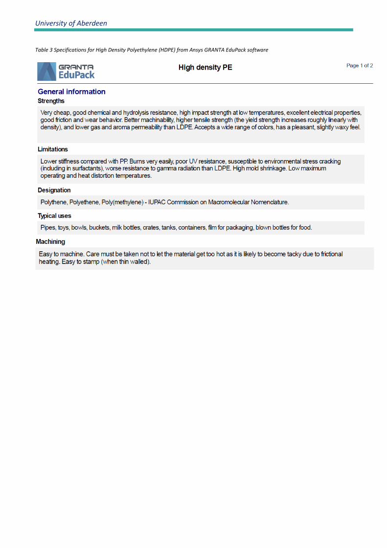
Table 3 Specifications for High Density Polyethylene (HDPE) from Ansys GRANTA EduPack software

Smartrawl Phase 2.5 Final Report
29
Annex 2. Computer code A1.1 Neural Network for fish detection Step 1. Debayering method

University of Aberdeen
Step 2. Image pre-processing

Smartrawl Phase 2.5 Final Report
31
Step 3. Mask R-CNN

University of Aberdeen
Step 5. Function integration

Smartrawl Phase 2.5 Final Report
33
Annex 3. Modem message specification CCSMS–Send short message (around 0.75S send 1 number) This is used to send a number from 0 to 9999 of data acoustically to another modem. This ensures the most efficient transmission method for short message packets. $CCSMS,0,1,XXXX*CS XXXX four digit number in decimal *CS Hex coded checksum CCFSS–Send short data block (around 2.2S send 4 numbers from 0-9999 coded into two bytes) This is used to send a short block (4 set of 4 digit numbers) of data acoustically to another modem. $CCFSS,0,1,0,XXXXYYYYZZZZPPPP*CS XXXX four digit number in decimal YYYY four digit number in decimal ZZZZ four digit number in decimal PPPP four digit number in decimal *CS Hex coded checksum CCFSD–Send data block (send more numbers from 0-9999 duration change depending on number send but minimum more than 4 sets of numbers) This is used to send a large block (more than 4 set of number) of data acoustically to another modem. $CCFSD,0,1,0,LLLL,XXXX…XXXX*CS LLLL Length =Number of set of 4 digit number divided by 2 and coded in hexadecimal value XXXX set of 4 digit number in decimal *CS Hex coded checksum Note, the maximum size for the data block is 500 sets of numbers, due to internal buffer limitations.