Embed Size (px)
Citation preview

KTH SE-. Tel: +46-8 790 7750. Fax: +46-8-790 6625.
E-post: [email protected]
1 (9)
Project Literature November, 2010
Electric Power Systems Division - School of Electrical Engineering
KTH Royal Institute of Technology
SmarTS-LAB: a Smart Transmission Grids Laboratory at KTH1 by Dr. Luigi Vanfretti
Associated Colleagues:
KTH EPS: Lennart Söder, KTH ICS: Moustafa Chenine, Lars Nördstrom Summary: In this document we propose the development of a Smart Transmission Grids Laboratory named (SmarTS-Lab - Smart Transmission Systems-Laboratory) to be developed jointly by KTH-EPS and KTH-ICS. This laboratory has the aim of serving as a test-bench where research enabling the future “Smart Grids” at the transmission level will be performed. To this aim, the SmarTS-Lab will be designed as a completely configurable system which will allow testing and development of power system operations methods and techniques; control methods, strategies, and algorithms; advanced protective system coordination with system controls; communication network paradigms and computer system architecture paradigms; information and communication technology design specifications - all under a completely controlled environment. This approach will allow the assessment of research ideas by subjecting them to a “near-real-world” power network (emulated by a highly accurate real-time simulator) and allowing gradual testing of the performance of our research ideas under near “real-world” conditions imposed by “actual” communication networks and computer system architectures. It is important to emphasize that this approach will bring to our research area a methodology that is not standard in similar research groups – a completely controlled environment where we can reproduce experiments. Therefore, this will allow for a very rigorous and careful assessment of new methods and techniques and to determine applications requirements for ICT; in addition to incorporating practical limitations, which are close to those present in the field. Recently, the European Institute of Technology (EIT) assigned KTH as a Smart Grids center. Within the EIT cooperation the proposed SmarTS-Lab will provide a suitable launching platform to develop innovative technologies for Smart Transmission Grids. Once established, the SmarTS-Lab can be used to develop innovative software/hardware solutions that can be used by transmission system operators worldwide. KTH’s long-standing collaboration with ABB and Vattenfall will provide an opportunity to establish the potential of the developed solutions within this EIT collaboration. This laboratory will also serve the larger research and education goals of the EPS and ICS departments at KTH. At EPS it will serve for on-going PhD and Master thesis projects, while it may also be used to perform illustrations for some courses. At ICS it will serve as a canvas where different paradigms of communication methods and computer system architectures for real-time operation of power systems can be demonstrated. This document provides background information and justifications to develop such simulator by KTH EPS and ICS.
1. Background The raising interest in “Smart Grids” has prompted an ever-increasing wave of discussion regarding a more disruptive introduction of information and communication technologies (ICT) to increase efficiency in electricity delivery and power network management. Much of the public debate has been centered on the use of ICT for distribution network management and automation, leaving the application of these technologies to transmission system somewhat outside this debate [1], of course with the exception of synchronized phasor measurement units (aka PMUs) and a few of their applications [2]. At the distribution side, most of the envisioned applications are technically feasible: there exists the necessary components from ICT and the required degree of
1 A white paper prepared for the School of Electrical Engineering of KTH.

KTH SE-. Tel: +46-8 790 7750. Fax: +46-8-790 6625.
E-post: [email protected]
2 (9)
automation needed to perform corrective and protective measures is possible with currently available power distribution assets. The on-going and ambitious addition of “smart meters” would allow in the near future for an even more granular management of distribution networks and additional ventures into demand response. Although there are still many challenges in this area, there exists many commercially available decision support computer and software systems, which can already exploit distribution assets, one of such is ABB’s MicroSCADA Pro [3] and ABB’s SCADA/DMS Network Manager [4], among others. From the author’s point of view, Smart Grids at the distribution level are more than technically feasible, the challenge lies at the transmission level. Currently at the transmission level most of the monitoring and control actions are performed in an Energy Management System (EMS), which makes use of a Supervisory Control and Data Acquisition (SCADA) system. There are many solutions available and currently used by transmission system companies and system operators, such as ABB’s SCADA/EMS Network Manager [5]. Although these systems are mature and dependable, it has not been until recently that features focusing on “wide-area” analysis have been implemented. In addition, most of these wide-area applications are mostly limited to monitoring and post-mortem (off-line) analysis of events through the use of either streamed or archived measurements. The new enabling technologies of so called wide-area monitoring systems are Phasor Measurement Units (PMUs) as the measurement device of choice, and their supporting infrastructure which is formed by communication networks and computer systems capable of handling PMU data and other information (usually called Phasor Data Concentrators (PDCs)). The set of PMUs and their enabling information and communication infrastructures is termed Synchrophasor Measurement Technology (SMT). With the rising number of synchrophasor installations around the world a window of opportunity opens for stakeholders in the transmission system to exploit the synchronization and higher resolution measurements provided by PMUs. However, the number of applications available to transmission operators for exploiting these measurements seems not to be sufficient to justify investments in SMT, and current projects dealing with installation of these devices are strongly subsidized [6]. Long-term development of these future power systems cannot rely on heavily subsided funding as its means to existence, and other economical drivers are needed. Hence, for the long term and sustained development of these technologies a different Research & Development (R&D) approach is necessary. 2. Motivat ion There are several reasons for the lack of SMT-based applications and their limited adoption. These reasons emerge from the two different development approaches currently used: application development using real PMU data, and the simulation approach. From a researcher’s stand point, obtaining real PMU data from transmission companies involves signing non-disclosure agreements which delays the start of research efforts (for about 1 to 2 years depending on the amount of paperwork), and more importantly, they may impose restrictions on the intellectual property of the derived works [7]. In addition, when developing PMU-based applications, the PMU data itself is not sufficient: knowledge about the transmission system model parameters during the archived data time frame and other data (such as bus-bar level breaker status) are crucial for some applications [8], and may not be easy to obtain. Also of consideration is that there aren’t any standard data sharing formats other than COMTRADE for PMU data, which is ill suited for research unlike others used among larger groups of researchers [9] and for many applications requiring large records of phasor measurements (from 1 day to even weeks of archived data [10]). The list of difficulties can be further extended; however, it is more important to note that these problems are not only faced by academic researchers but also by several industrial research entities, therefore delaying the industrial development and adoption of PMU-based applications. There are simply too many practical difficulties to develop these PMU applications at a faster pace solely depending on measurement obtained through transmission utilities. On the other hand many academics have proposed some applications of PMU data based solely on simulations using software commonly used in the power industry (which are mostly positive sequence-based (or phasor) simulations). While this approach is suited for some fundamental research, it might not be appropriate for actual implementation. This is because this approach does not take into account
KTH SE-. Tel: +46-8 790 7750. Fax: +46-8-790 6625.
E-post: [email protected]
3 (9)
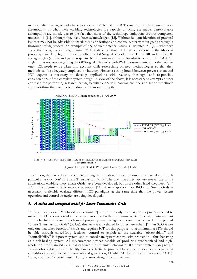
many of the challenges and characteristics of PMUs and the ICT systems, and thus unreasonable assumptions of what these enabling technologies are capable of doing are made. Unreasonable assumptions are mostly due to the fact that most of the technology limitations are not completely understood [11], although they have been acknowledged [12]. Without full consideration of practical issues it may not be advisable to install these applications at a control center without going through a thorough testing process. An example of one of such practical issues is illustrated in Fig. 1, where we show the voltage phasor angle from PMUs installed at three different substations in the Mexican power system. This figure shows the effect of GPS-signal loss of in the THP-LBR and LBR-THP voltage angles (in blue and green, respectively), for comparison a red line-dot trace of the LBR-GUAT angle shows no issues regarding the GPS-signal. This issue with PMU measurements, and other similar ones [12], needs to be taken into account while researching on new methodologies so that they methods can be adequately employed by industry. Hence, a strong bound between power system and ICT experts is necessary to develop applications with realistic, thorough, and responsible considerations of the complete system design. In view of the above, it is necessary to attempt another approach for performing research leading to suitable analysis, control, and decision support methods and algorithms that could reach industrial use more promptly.
GPS Issues - I! What would be the impact of a major failure of the GPS system on Smart TransmissionGrids?
08:28:49.440 08:28:53.760 08:28:58.080 08:29:02.400 08:29:06.720 08:29:11.040 08:29:15.360 08:29:19.680
!150
!100
!50
0
50
100
150
Time (HH:MM:SS)
Vol
tage
Ang
le (d
eg)
MEXICO!SIEPAC Interconnection / 11/26/2009
THP!LBR (GPS Sig. Lost)LBR!GUATLBR!THP (GPS Sig. Lost)
! Several PMU manufacturers do not include an internal flywheel oscillator to keeptrack of the timing in case of GPS signal loss (only accommodates for outages of shortduration)! What would happen in rolling blackouts when we need PMUs the the most?! There is research on Chip Scale Atomic Clocks - will retain synchronization forweeks, but still under research.! Smart Transmission Grids applications using PMU data must be %100 reliable, howwill they deal with this problem?! What about hostile GPS signal corruption?
c!L. Vanfretti (KTH-EPS) PMU Data Applications June 10, 2010 52 / 63
Figure 1 - Effect of GPS-Signal Loss in PMU Data
In addition, there is a dilemma on determining the ICT design specifications that are needed for each particular “application” in Smart Transmission Grids. The dilemma arises because not all the future applications enabling these Smart Grids have been developed, but in the other hand they need “an” ICT infrastructure to take into consideration [11]. A new approach for R&D for Smart Grids is necessary to flexibly evaluate different ICT paradigms at the same time that the power system operation and control strategies are being developed. 3. A vis ion and concep tua l mode l fo r Smart Transmiss ion Grids In the author’s view PMU-based applications [2] are not the only necessary developments needed to make Smart Grids successful at the transmission level – there are more assets to be taken into account and to be fully exploited by advanced power system management systems which will form part of “Smart Transmission Grids” (STGs), this view is also shared by other researchers [1]. An STG is not only one that takes benefit of PMUs and requires ICT for this purpose – at a minimum, a STG should be able through closed-loop feedback control to exploit all the available “observability” and “controllability” in a power system, and to coordinate system control with protection – thus behaving as a self-healing system. All measurement devices capable of producing synchronized and high-resolution time-stamped data that captures the dynamic behavior of the power system can provide system observability. Controllability can be effectively provided by all those devices that can be in closed-loop control including conventional generation, Flexible AC Transmission Systems (FACTS), Voltage Source Converter based HVdc, phase-shifting transformers, etc.

KTH SE-. Tel: +46-8 790 7750. Fax: +46-8-790 6625.
E-post: [email protected]
4 (9)
To accomplish these ambitions, we have developed a vision of “Smart Transmission Grids” (STGs) at KTH, which is comprised of more than the high-resolution measurements provided by PMUs. In Fig. 2 a conceptual diagram of a “centralized model” for a Smart Transmission Grid is shown. In such STG synchronized measurements are obtained at transmission substations through PMUs or other synchrophasor-capable devices, in addition to these measurements, synchronized and highly accurate measurements from controllable devices such as FACTS, VSC-HVdc, etc, and protective device “information set” (which would include the device status, measurements, and other available information) are sent through communication networks. These data is received and processed so that a Decision/Control Support System determines appropriate preventive, corrective and protective measures. This support system is the cornerstone for enabling STGs, here is where the newly developed analysis techniques will produce “smarter” decisions allowing the power system to operate more securely, efficiently, and reliably. The decisions determined by this support system will then support operators at control centers to take “smarter operator control actions” or even device “smart-automatic control/protective actions”. These actions are translated into feedback signals that are sent through communication networks to exploit the controllability and protection resources of the power system.
Smart Transmission Grids - How?A Self-Healing System:
Measure ! Communicate ! Analyze (System Assessment and Real Limits)! Determine Preventive/Corrective Actions ! Communicate ! Control and Protect
(In many cases this process should be completed in milliseconds)
!"#$%&'()(#*
+,-./0&12-.302)2#4&5-4-
6/#40/77-872&-#9&+0/42$4(:2&52:($2&12-.302)2#4&-#9&!4-43.&5-4-
5-4-&;7(*#)2#4-#9
6/#$2#40-4(/#
6/)
)3#
($-4(/#&<24=/0>.
5-4-&!4/0-*2
'0-#.)(..(/#&!".42)&6/#40/7&62#420
!"#$%"&$#'
()*+#,-)./$012+30
4+&23.5+&#$#'.630%-7
8-+&.9-+2:;$7-/3#+7$,.6-,<&$%3
(00-007-#% (<%"7+%$,./-%-&7$#+%$"#."=>"#%&"2.(,%$"#0
52$(.(/#?6/#40/7&!3@@/04&!".42)
!)-04A;34/)-4($&6/#40/7&;$4(/#.
!)-0420&B@20-4/052$(.(/#&!3@@/04
!)-0420&B@20-4/0&6/#40/7&;$4(/#.
" This process does not have to be centralized, other ideas include distributed andmore flexible fdbk control." Fast, reliable, and cost-e!ective two-way communication is imperative.
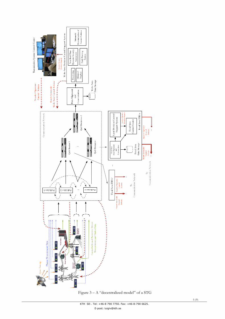
Figure 2 – A centralized model of a Smart Transmission Grid Note that although the diagram shown in Fig. 2 is a centralized model there could be other more decentralized models for STGs. A “decentralized model” of a STG is shown in Fig. 3. Observe that in this paradigm we have divided the operation of the system into “focal area” systems with different operational functions (some of them might not include a focal area control center for example, implying that only other functions are taken there and thus a lower amount of data with perhaps lower Quality of Service (QoS) is needed) and a “wide-area” system. The data delivery is done through a publisher-subscriber model instead of a traditional star communication with round-robin polling model used in the centralized model. This is because it has been acknowledged that the centralized model would be overwhelmed by the data volume produced by the power system today even at the substation level. The different routers gathering data from several subscribers can be grouped on QoS Broker assigning different degrees of flexibility and data rate depending on the needs [14]. The interfaces in this publisher-subscriber model need to be pursued using Middleware as done for example in [12]. However, as mentioned before, the whole architecture of the system faces a dilemma because it will be determined by the requirements from different applications using PMU data, controllable devices, and protective devices which need the ICT infrastructure to be developed – in other words, how and for what purpose the measurement and other data be used will determine the most cost efficient system architecture, but “an” architecture is needed to obtain data to develop the applications. To find the appropriate architecture that will fit the needs of future power systems an appropriate platform for research is needed.
KTH SE-. Tel: +46-8 790 7750. Fax: +46-8-790 6625.
E-post: [email protected]
5 (9)
Figure 3 – A “decentralized model” of a STG

KTH SE-. Tel: +46-8 790 7750. Fax: +46-8-790 6625.
E-post: [email protected]
6 (9)
4. KTH SmarTS-Lab To tackle the difficulties from the two development methods discussed above, and using the “centralized model” in Fig. 2 as reference, we next explain our proposal for the SmarTS-Lab as depicted in Fig. 4. Observe that the laboratory will not be “hardwired” as a centralized system, but can be configured for different ICT infrastructures depending on the power system application needs.
Figure 4 – SmarTS-Lab “Magnus” Configuration
The proposed laboratory in Fig. 4 would be the ideal case using the “centralized model”. In this configuration, the power system is emulated by a highly accurate and detailed real-time power system simulator capable of providing sufficient measurements of both analog and digital quantities of a test power network. For this real-time simulator several commercial options exist, and we have not yet made a final decision on which one would be purchased [15, 16] because this would be contingent on funding. In addition, this simulator is able of receiving analog and digital signal that would be used to evaluate the performance of control strategies and algorithms. This kind of simulator is ideal for closed-loop feedback control [17]. The outputs from the simulator can be feed into actual PMUs and other devices such as RTUs, which will directly send their calculated measurements through a communication network. The communication network will likely be a LAN network that is formed by routers and dedicated computers. With this approach the kind of communication network is not fixed and several paradigms can be tested, however, for flexibility, an intermediate layer allowing the use of different paradigms is necessary. This can be accomplished by developing appropriate Middleware. The data will be received for alignment and concentration, a task likely to be carried out using openPDC [18]. After all measurements are put into a synchronized stream they can be sent out to a “STG Engine”. In this engine is where all proposed methods and techniques will be implemented. A list of possible methods appears in the gray box in Fig. 4. Initially this can be pursued using the plug-in functionality for application development in openPDC using a combination of the .NET framework and MATLAB, but this can be moved to a different platform other than openPDC at a later stage.

KTH SE-. Tel: +46-8 790 7750. Fax: +46-8-790 6625.
E-post: [email protected]
7 (9)
Control, preventive, and correction actions devised in the STG will be transferred again through a communication network, and thus, a Middleware intermediate layer might be necessary for this purpose. These “actions” include input signals for feedback control and equipment tripping, which can be feed into the simulator directly, actual protective equipment and controller prototypes which could even at the same time feed scaled-down prototypes of controllable devices (such as FACTS). Hence, this allows for a complete “hardware-in-the-loop” (HIL) approach, and equipment such as protection relays and controllers feed their final signals directly into the simulator.
Figure 5 – SmarTS-Lab “Elementum” Configuration
Observe that in this concept for the SmarTS-Lab we are trying to reproduce, as close as possible, the real behavior in “real” power systems. However, we realized that this may not be completely possible at an initial stage, and thus, we consider additional configurations where we could start developing research ideas. One of these configurations is the so-called “Elementum” configuration. Here we consider only the simulator and the STG Engine as the major pieces of our laboratory. In this case they would be linked through a direct A/D and D/A computer link which would transfer the analog and digital outputs of the simulator to a protocol such as IEEE C37.118 or IEC 61850, hence, this links would also be accomplished by implementing Middleware in a dedicated computer. The STG Engine will continue to rely on openPDC as described above for the “Magnus” configuration in Fig. 4.
Figure 6 – SmarTS-Lab “Vigilo” Configuration

KTH SE-. Tel: +46-8 790 7750. Fax: +46-8-790 6625.
E-post: [email protected]
8 (9)
There are additional configurations that we have envisioned, one of them being the “Vigilo” configuration, which would now replace the dedicated computer link to an actual LAN. For this purpose for both sending and receiving data from the STG a similar approach as in the “Elementum” configuration is needed. 5. Scien t i f i c Impac t The development of this unique laboratory will provide KTH EPS and ICS a fundamental advantage to pursue truly innovative ideas beyond the capability of the R&D methodologies explained in Section 1. Thus, it is expected that valuable scholarly and practical contributions to the development of future power systems be made by means of this laboratory and a strong collaboration with KTH EPS and ICS. It is expected that KTH EPS will develop innovative control strategies, optimized operation methods, stability assessment techniques, and many other novel contributions focusing on wide-area applications, which would enable Smart Transmission Grids in the future. This will not be possible without the parallel development of ICT paradigms, specification of ICT design, and the proposal of innovative ICT technologies, which can be deployed considering the important aspects of farsighted planning and responsible investment commitment.
6. Relat ion wi th EIT’s KIC InnoEnergy Consor t ium and Industr ia l Impac t Recently the European Institute of Technology (EIT) assigned KTH as a Smart Grids center. Within the EIT cooperation the proposed SmarTS-Lab will provide a suitable launching platform to develop innovative technologies for Smart Transmission Grids. Once established, the SmarTS-Lab can be used to develop innovative software solutions that can be used by transmission system operators worldwide. KTH’s long-standing collaboration with ABB and Vattenfall will provide an opportunity to establish the potential of the developed solutions within this EIT collaboration. It is difficult to foresee the exact level of industrial impact from the development of this lab and derived works, however, given the established collaborations with SvK and ABB it is expected that viable products can be further developed and implemented by our industrial partners. 7. Resource s
KTH EPS will seek funding for the real-time simulator and some additional hardware necessary for closed-loop feedback applications and the STG Engine(s). KTH ICS will seek funding for the information and communication technologies, hardware, software and middleware needed to provide communication between the real-time simulator and the STG Engine(s).
8. Contac t
For additional information, contact:
Dr. Luigi Vanfretti http://www.vanfretti.com Assistant Professor Royal Institute of Technology Electric Power Systems Division Stockholm, Sweden Phone: +46-8 790 6625 Cellular: +46- 07 27356601 Fax: +46-8-790 6510
KTH SE-. Tel: +46-8 790 7750. Fax: +46-8-790 6625.
E-post: [email protected]
9 (9)
9. Refer ence s
[1] Lambert, E.; Fremont, J.; Bouquet, C.; , "Method and applications of IEC common information model standard for distribution operations : A path towards smart grids development," SmartGrids for Distribution, 2008. IET-CIRED. CIRED Seminar , vol., no., pp.1-4, 23-24 June 2008
[2] De La Ree, J.; Centeno, V.; Thorp, J.S.; Phadke, A.G.; , "Synchronized Phasor Measurement Applications in Power Systems," Smart Grid, IEEE Transactions on , vol.1, no.1, pp.20-27, June 2010
[3] MicroSCADA Pro DMS 600 4.3 System Overview. On-line: http://tiny.cc/microscada_abb [4] Network Manager SCADA/DMS – Distribution Network Management. On-line:
http://tiny.cc/abb_scadadms [5] Network Manager – Energy System Operation. Available On-line:
http://tiny.cc/abb_netmngr [6] US Department of Energy, “Smart Grid Investment Grant Selectee Information,” On-line:
http://www.oe.energy.gov/recovery/1264.htm [7] North American Synchrophasor Initiative, “NASPI Phasor Data NDAs”. On-line:
http://www.naspi.org/nda/nda.stm [8] Mladen Kezunovic, “Merging PMU, operational and non-operation data for interpreting
alarms, locating faults and preventing cascades,” NASPI Workgroup Meeting, June 3-4, 2009, Sacramento, California. On-line: http://www.naspi.org/meetings/workgroup/2009_june/presentations/kezunovic_tamu_merging_pmu_20090604.pdf
[9] The HDF Group, “Hierarchical Data Format”. On-line: http://www.hdfgroup.org/ [10] L. Vanfretti, R. Garci ́a-Valle, K. Uhlen, E. Johansson, D. Trudnowski, J. W. Pierre, J. H.
Chow, O. Samuelsson, J. Østergaard, K. E. Martin, “Estimation of Eastern Denmark’s Electromechanical Modes from Am- bient Phasor Measurement Data”, to appear in Proceedings of the IEEE PES General Meeting, 2010. http://idisk.me.com/vanfretti/Public/publications/conference/10_LV_RV_DKModeEst_PESGM2010_v2.pdf
[11] Chenine, M.; Nordstrom, L.; , "Investigation of communication delays and data incompleteness in multi-PMU Wide Area Monitoring and Control Systems," Electric Power and Energy Conversion Systems, 2009. EPECS '09. International Conference on , vol., no., pp.1-6, 10-12 Nov. 2009.
[12] Gjermundrod, H.; Bakken, D.E.; Hauser, C.H.; Bose, A.; , "GridStat: A Flexible QoS-Managed Data Dissemination Framework for the Power Grid," Power Delivery, IEEE Transactions on , vol.24, no.1, pp.136-143, Jan. 2009.
[13] Vanfretti, L.; Chow, J. H.; Sarawgi, S.; Fardanesh, B. (B.).; , "A Phasor-Data-Based State Estimator Incorporating Phase Bias Correction," accepted for future publication in IEEE Transactions on Power Systems.
[14] Bose, A.; , "Smart Transmission Grid Applications and Their Supporting Infrastructure," Smart Grid, IEEE Transactions on , vol.1, no.1, pp.11-19, June 2010
[15] Opal-RT Technologies, “eMegaSim Real-Time Simulator”. On-line: http://www.opal-rt.com/
[16] RTDS Technologies, “Real Time Digital Simulator – RTDS”. On-line: http://www.rtds.com/index/index.html
[17] Majumder, R.; Pal, B.C.; Dufour, C.; Korba, P.; , "Design and real-time implementation of robust FACTS controller for damping inter-area oscillation," Power Systems, IEEE Transactions on , vol.21, no.2, pp. 809- 816, May 2006.
[18] Protective Grid Alliance, “openPDC”. Available on-line: http://openpdc.codeplex.com/