Embed Size (px)
Citation preview

SmartScan User's Manual
for SmartScan 25/50

SmartScan User’s Manual
ii
Important Notice This manual is delivered subject to the following conditions and restrictions:
This manual contains proprietary information belonging to Solid Applied Technologies Ltd. Such information is supplied solely for the purpose of assisting explicitly and properly authorized users of SmartScan.
No part of its contents may be used for any other purpose, disclosed to any person or firm or reproduced by any means, electronic or mechanical, without the express prior written permission of Solid Technologies Ltd.
The text and graphics are for the purpose of illustration and reference only. The specifications on which they are based are subject to change without notice.
Information in this document is subject to change without notice. Corporate and individual names and data used in examples herein are fictitious unless otherwise noted.
Copyright © 2004. All rights reserved.
SmartScan® is a trademark of Solid Applied Technologies Ltd.
Other company and brand products and service names are trademarks or registered trademarks of their respective holders.
Date Revision Software Version Catalog Number
June, 2004 2.1 5.06 - 5.07
2.05 - 2.06
680003C

Safety Guidelines
iii
Safety Guidelines Please review the following points before installing and operating the SmartScan system.
SmartScan must be installed, connected and operated according to the instructions in this Manual.
If installed incorrectly or used for applications for which it is not intended, application-related dangers may arise.
Only qualified personnel are authorized to install and operate SmartScan.
When SmartScan is reopened, ensure that you replace the O-ring, in order that the unit will remain sealed (for IP67 units). The O-ring is suitable for one use only.
Modifications and repairs to SmartScan are permissible only when the manufacturer expressly approves them.
SmartScan User’s Manual
iv
Table of Contents
Chapter 1: Introducing SmartScan............................................... 1
Sensor Dimensions ........................................................................................ 6
SmartScan 25 Specifications .......................................................................... 8
SmartScan 50 Specifications ........................................................................ 12
Sensor Recommendations............................................................................ 15
Sensor Cable Recommendations.................................................................. 16
Chapter 2: Installing SmartScan................................................. 19
Precautions ................................................................................................. 19
Installing the SmartScan Sensor .................................................................. 20
Threading Options................................................................................... 21
Sensor Positioning ................................................................................... 24
Installing the Sensor via an Extension Pipe .............................................. 26
Wiring the SmartScan Unit ......................................................................... 28
Wiring the Sensor Cable .......................................................................... 29
Wiring the Monitoring Cables.................................................................. 31
Wiring the Relays Cable .......................................................................... 32
Wiring VDC Power Cable........................................................................ 33
Wiring VAC Power Cable ........................................................................ 33
SmartScan 25 Intrensically Safe Connections........................................... 34
Chapter 3: Basic Setup............................................................... 40
Using the SmartScan Function Buttons ....................................................... 42
Modifying Numerical Values ................................................................... 43
4BTable of Contents
v
Menu and Version Selection........................................................................ 44
Accessing the Main Menu ........................................................................... 45
Using the Main Menu.............................................................................. 46
Default Screen............................................................................................. 47
Setting Main Menu Options ........................................................................ 49
Setting the Indication Mode..................................................................... 50
Setting the Measurement Unit.................................................................. 52
Setting the Relay Values for SmartScan 50 ............................................... 54
Setting the Relay Values for SmartScan 25 ............................................... 63
Setting the 20 mA/4 mA Levels ................................................................ 65
Setting the Flow Measurements ............................................................... 66
Setting the Tank Height............................................................................ 67
Setting the Application Type.................................................................... 69
Setting the Operation Modes ................................................................... 70
Setting the Sensor Offset .......................................................................... 72
Setting the Scan Distance Values ............................................................. 74
Clearing the Scan Distance Values .......................................................... 77
Viewing Processor Information ................................................................... 77
Chapter 4: SmartScan Open Channels........................................79
Selecting the Flow Measurement Settings ................................................... 79
Open Channels Flow Measurements ........................................................... 81
Flume/Weir Types.................................................................................... 82
European Standard .................................................................................. 83
Rectangular Suppressed Sharp-crested Weir (Type 1) .............................. 83
Rectangular Contracted Sharp-crested Weir (Type 2)............................... 84
Trapezoidal (Cipolletti) Sharp-crested Weir (Type 3)................................ 85
V-notch (Triangular) Sharp-crested Weir (Type 4) .................................... 86
SmartScan User’s Manual
vi
Khafagi-Venturi Flume (Type 5) ............................................................... 87
Parshall Flume (Type 6) ........................................................................... 88
Palmer Bowls Flume Trapezoidal Throat Cross-selection (Type 7) ........... 89
H Flume (Type 8)..................................................................................... 90
Neyrpic Venturi Flume/Long-base Weir (Type 9) ..................................... 91
American Standard ................................................................................. 93
Rectangular Suppressed Sharp-crested Weir (Type 1) .............................. 93
Rectangular Contracted Sharp-crested Weir (Type 2)............................... 94
Trapezoidal (Cipolletti) Sharp-crested Weir (Type 3) ............................... 95
V-notch (Triangular) Sharp-crested Weir (Type 4) .................................... 96
Parshall Flume (Type 5) ........................................................................... 97
Palmer Bowls Flume Trapezoidal Throat Cross-selection (Type 6) ........... 98
H Flume (Type 7)..................................................................................... 99
Leopold Lagco Flume (Type 8) .............................................................. 100
Chapter 5: Additional Features ................................................ 101
Accessing the Additional Menu................................................................. 102
Setting Additional Menu Options.............................................................. 103
Selecting an Indication .......................................................................... 104
Manually Inserting Strapping Table Values ............................................ 106
Semi-automatic Inserting of Strapping Table Values .............................. 108
Inserting a Coefficient for Readings ....................................................... 110
Erasing Strapping Table Values.............................................................. 112
Configuring Height for a Cone............................................................... 113
Defining 22mA/3.7mA Signal Error Messages........................................ 114
Entering Factor for Gas Compensation in SmartScan 25 ........................ 116
4BTable of Contents
vii
Chapter 6: Diameter Mode Setup.............................................118
Using Diameter Sum Option ..................................................................... 123
Chapter 7: Troubleshooting SmartScan ....................................125
Appendix A: SmartScan Ranges ................................................128
Appendix B: Gas Factor Table ..................................................130
Index........................................................................................133
SmartScan User’s Manual
viii
Table of Figures Figure 1: Front View of SmartScan ......................................................... 3
Figure 2: Side View of SmartScan ........................................................... 3
Figure 3: Wall-mount Plate..................................................................... 4
Figure 4: Back View of SmartScan with Wall-mount Plate ...................... 4
Figure 5: Panel Mount ............................................................................ 5
Figure 6: Top View of SmartScan with Panel-mount Installation............. 5
Figure 7: SmartScan Sensor Dimensions ................................................. 6
Figure 8: Sensor Threading Options...................................................... 21
Figure 9: Sensor Positioning.................................................................. 24
Figure 10: Extension Pipe Installation ................................................... 26
Figure 11: Electrical Unit...................................................................... 28
Figure 12: SmartScan Main Menu Screen ............................................. 41
Figure 13: SmartScan Default Screen.................................................... 47
Figure 14: Tank Height ......................................................................... 74
Figure 15: Scan Distance Process.......................................................... 77
Figure 16: Rectangular Suppressed Sharp-crested Weir ........................ 83
Figure 17: Rectangular Contracted Sharp-crested Weir ........................ 84
Figure 18: Trapezoidal (Cipolletti) Sharp-crested Weir......................... 85
Figure 19: V-notch (Triangular) Sharp-crested Weir ............................. 86
Figure 20: Khafagi-Venturi Flume ......................................................... 87
Figure 21: Parshall Flume ..................................................................... 88
Figure 22: Palmer Bowls Flume Trapezoidal Throat Cross-selection ..... 89
5BTable of Figures
ix
Figure 23: H Flume............................................................................... 90
Figure 24: Neyrpic Venturi Flume ........................................................ 91
Figure 25: Long-base Weir.................................................................... 92
Figure 26: Leopold-Lagco Flume......................................................... 100
Figure 27: Cone Height ...................................................................... 113
Figure 28: Measuring Rolls Diameter ................................................. 118
Introducing SmartScan CHAPTER 1
1
Chapter 1
Introducing SmartScan SmartScan is a non-contact, ultrasonic, continuous-level measurement instrument that is able to provide accurate measurements for both liquids and solids, while automatically compensating for changes in temperature and other environmental conditions. SmartScan is designed for applications such as process tanks, storage vessels, open air piles, open channels, and so on.
SmartScan is a four-wire, low-voltage device, and is available with a customized graphic LCD display. SmartScan has two major components, the main control unit and the sensor (connected via a cable).
Main (electronic) control unit: If required, this component can be optionally wall mounted, using a wall-mount plate, or panel mounted. To ensure proper operation, the unit must be installed up to 200 m (656 ft) from the sensor and 100m (328 ft) for EX sensors.
Sensor and data cable: The sensor is supplied with the data cable attached. See description of available cable lengths in Page 16.
The installation procedure and wiring connections for these components are described in Chapter 2, Installing SmartScan.
SmartScan User’s Manual
2
The SmartScan product line comprises two families, SmartScan 25 (25 KHz) and SmartScan 50 (50 KHz), each with its own models (as listed below). A variety of sensors are available for SmartScan 25, suitable for different ranges.
SmartScan 25:
SmartScan L for liquid (Standard Range/Long Range)
SmartScan S for solid (Standard Range/Long Range)
SmartScan O for open channel (Standard Range/Long Range)
SmartScan R for Liquid short Range
SmartScan 50:
SmartScan L for liquid
SmartScan S for solid
SmartScan O for open channel
SmartScan D for diameter
Introducing SmartScan CHAPTER 1
3
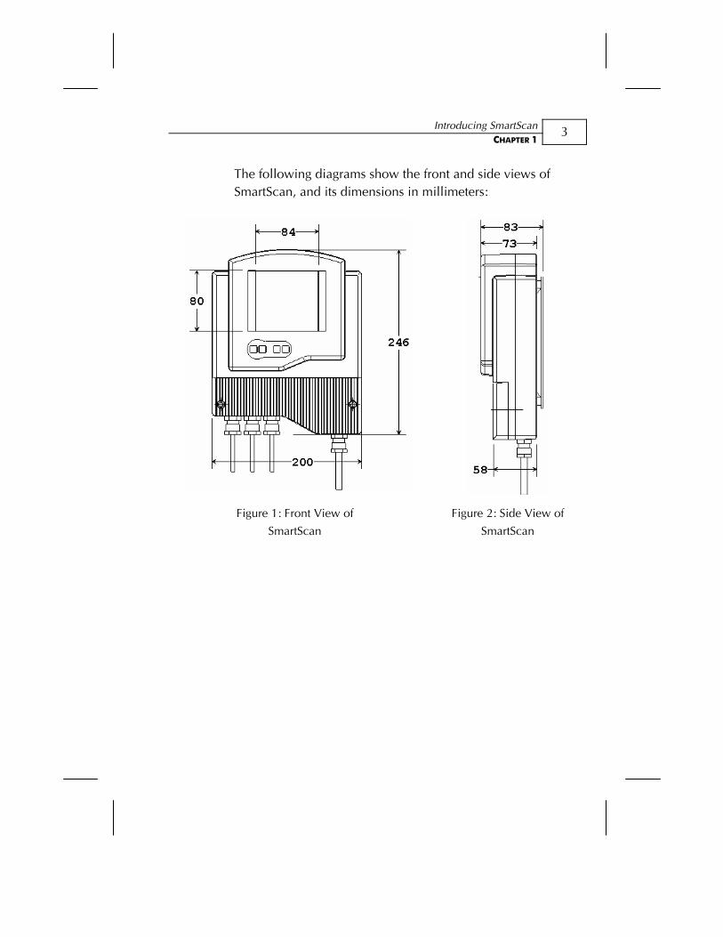
The following diagrams show the front and side views of SmartScan, and its dimensions in millimeters:
Figure 1: Front View of
SmartScan
Figure 2: Side View of
SmartScan
SmartScan User’s Manual
4
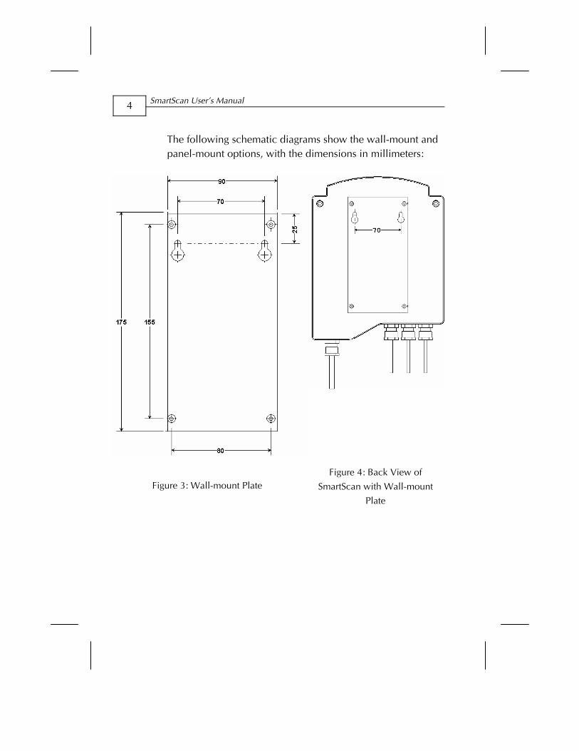
The following schematic diagrams show the wall-mount and panel-mount options, with the dimensions in millimeters:
Figure 3: Wall-mount Plate Figure 4: Back View of
SmartScan with Wall-mount
Plate
Introducing SmartScan CHAPTER 1
5
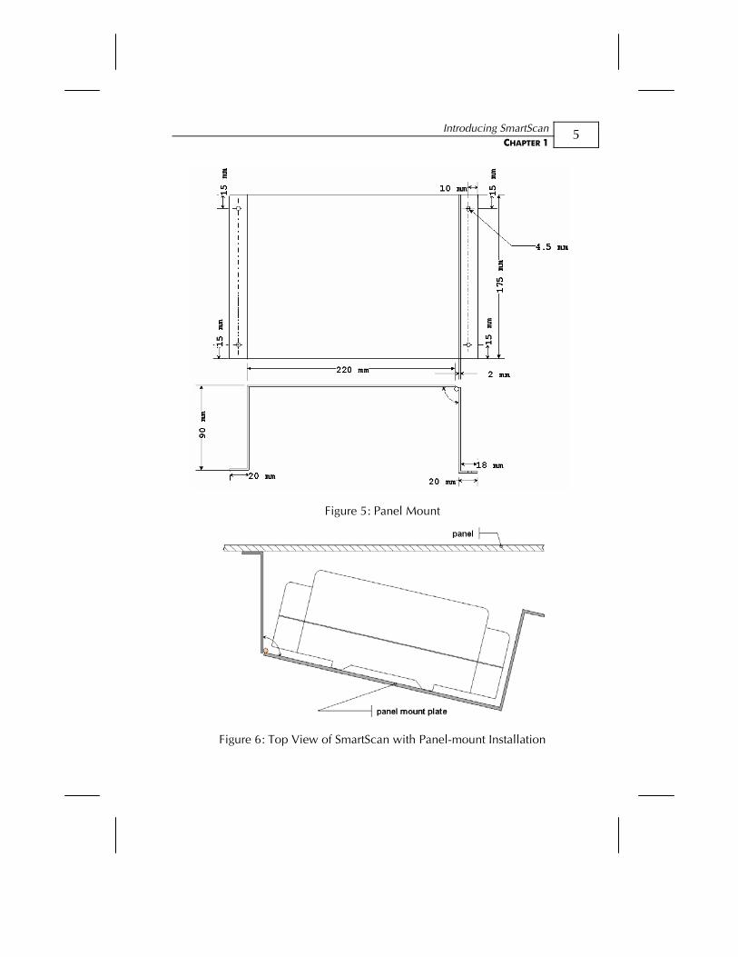
Figure 5: Panel Mount
Figure 6: Top View of SmartScan with Panel-mount Installation
SmartScan User’s Manual
6
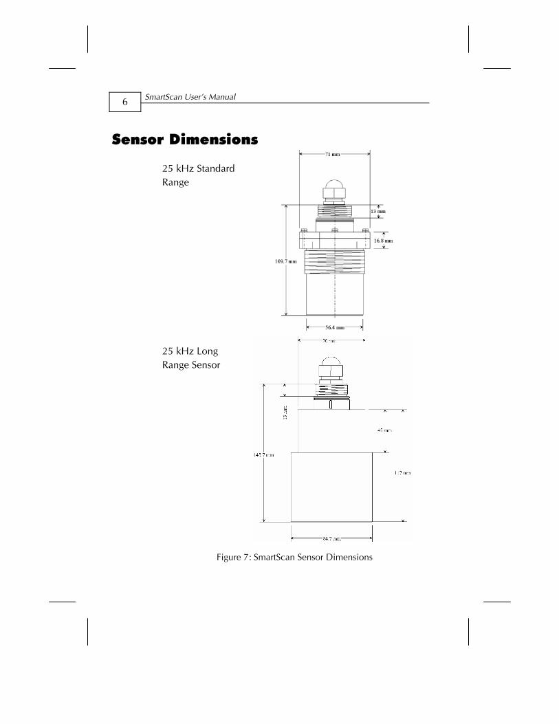
Sensor Dimensions
25 kHz Standard Range
25 kHz Long Range Sensor
Figure 7: SmartScan Sensor Dimensions
Introducing SmartScan CHAPTER 1
7
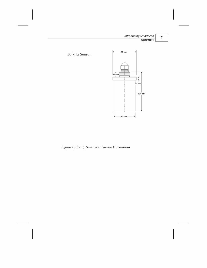
50 kHz Sensor
Figure 7 (Cont.): SmartScan Sensor Dimensions
SmartScan User’s Manual
8
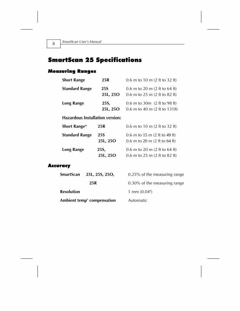
SmartScan 25 Specifications
Measuring Ranges
Short Range 25R 0.6 m to 10 m (2 ft to 32 ft)
Standard Range 25S 25L, 25O
0.6 m to 20 m (2 ft to 64 ft) 0.6 m to 25 m (2 ft to 82 ft)
Long Range 25S, 25L, 25O
0.6 m to 30m (2 ft to 98 ft) 0.6 m to 40 m (2 ft to 131ft)
Hazardous Installation version:
Short Range* 25R 0.6 m to 10 m (2 ft to 32 ft)
Standard Range 25S 25L, 25O
0.6 m to 15 m (2 ft to 49 ft) 0.6 m to 20 m (2 ft to 64 ft)
Long Range 25S, 25L, 25O
0.6 m to 20 m (2 ft to 64 ft) 0.6 m to 25 m (2 ft to 82 ft)
Accuracy
SmartScan 25L, 25S, 25O,
25R
0.25% of the measuring range
0.30% of the measuring range
Resolution 1 mm (0.04")
Ambient temp’ compensation Automatic
Introducing SmartScan CHAPTER 1
9
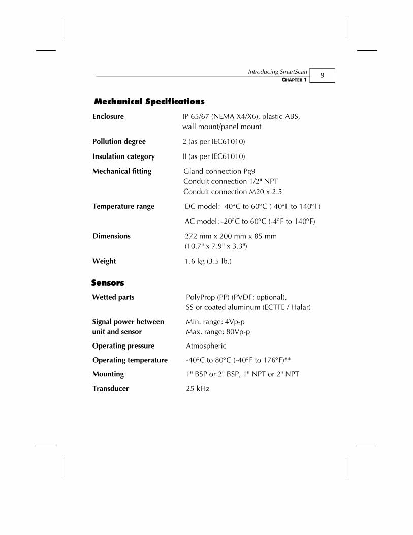
Mechanical Specifications
Enclosure IP 65/67 (NEMA X4/X6), plastic ABS, wall mount/panel mount
Pollution degree 2 (as per IEC61010)
Insulation category II (as per IEC61010)
Mechanical fitting Gland connection Pg9 Conduit connection 1/2" NPT Conduit connection M20 x 2.5
Temperature range DC model: -40°C to 60°C (-40°F to 140°F)
AC model: -20°C to 60°C (-4°F to 140°F)
Dimensions 272 mm x 200 mm x 85 mm (10.7" x 7.9" x 3.3")
Weight 1.6 kg (3.5 lb.)
Sensors
Wetted parts PolyProp (PP) (PVDF: optional), SS or coated aluminum (ECTFE / Halar)
Signal power between unit and sensor
Min. range: 4Vp-p Max. range: 80Vp-p
Operating pressure Atmospheric
Operating temperature -40°C to 80°C (-40°F to 176°F)**
Mounting 1" BSP or 2" BSP, 1" NPT or 2" NPT
Transducer 25 kHz
SmartScan User’s Manual
10
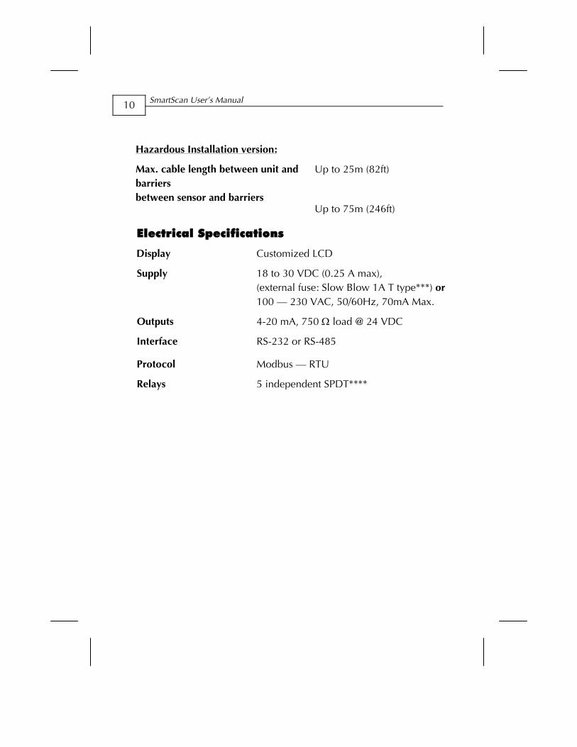
Hazardous Installation version:
Max. cable length between unit and barriers between sensor and barriers
Up to 25m (82ft)
Up to 75m (246ft)
Electrical Specifications
Display Customized LCD
Supply 18 to 30 VDC (0.25 A max), (external fuse: Slow Blow 1A T type***) or 100 — 230 VAC, 50/60Hz, 70mA Max.
Outputs 4-20 mA, 750 Ω load @ 24 VDC
Interface RS-232 or RS-485
Protocol Modbus — RTU
Relays 5 independent SPDT****
Introducing SmartScan CHAPTER 1
11
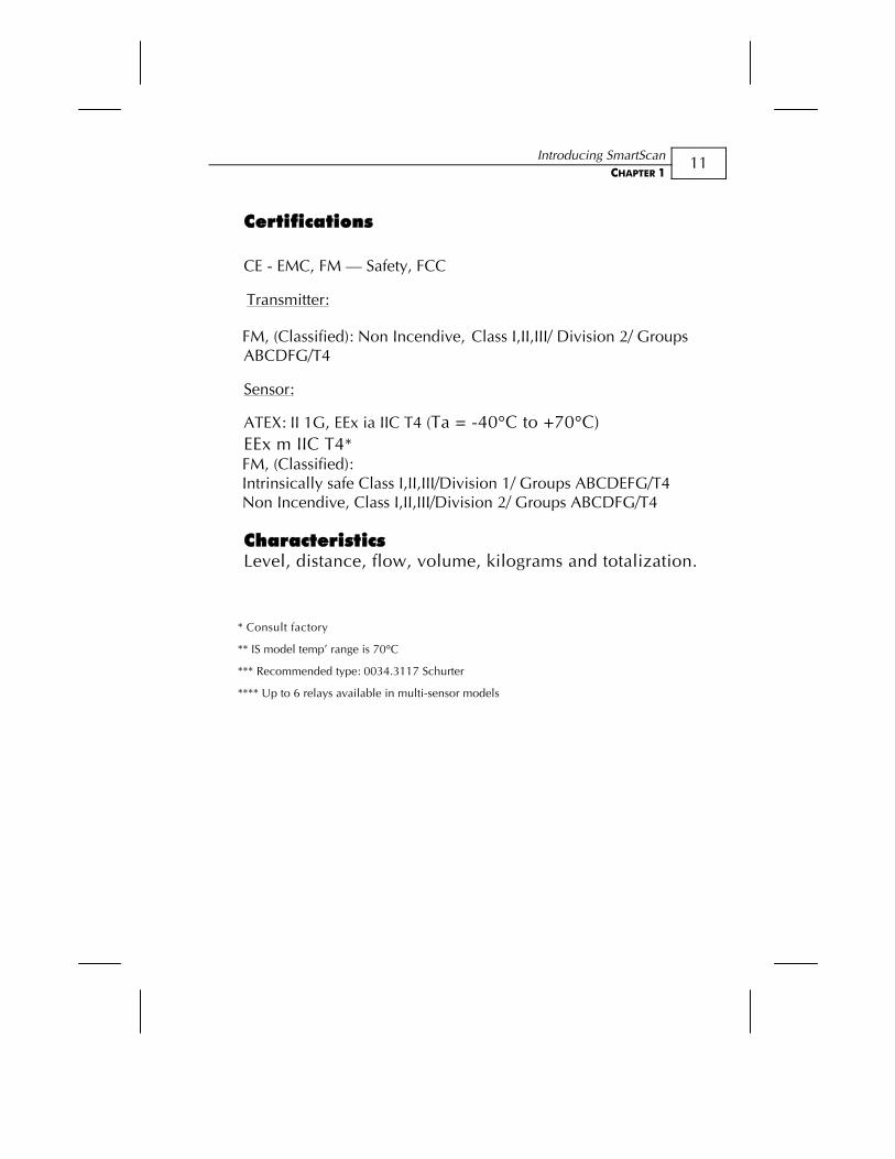
Certifications CE - EMC, FM — Safety, FCC
Transmitter:
FM, (Classified): Non Incendive, Class I,II,III/ Division 2/ Groups ABCDFG/T4
Sensor:
ATEX: II 1G, EEx ia IIC T4 (Ta = -40°C to +70°C) EEx m IIC T4*
FM, (Classified): Intrinsically safe Class I,II,III/Division 1/ Groups ABCDEFG/T4 Non Incendive, Class I,II,III/Division 2/ Groups ABCDFG/T4
Characteristics Level, distance, flow, volume, kilograms and totalization.
* Consult factory
** IS model temp’ range is 70°C
*** Recommended type: 0034.3117 Schurter
**** Up to 6 relays available in multi-sensor models
SmartScan User’s Manual
12
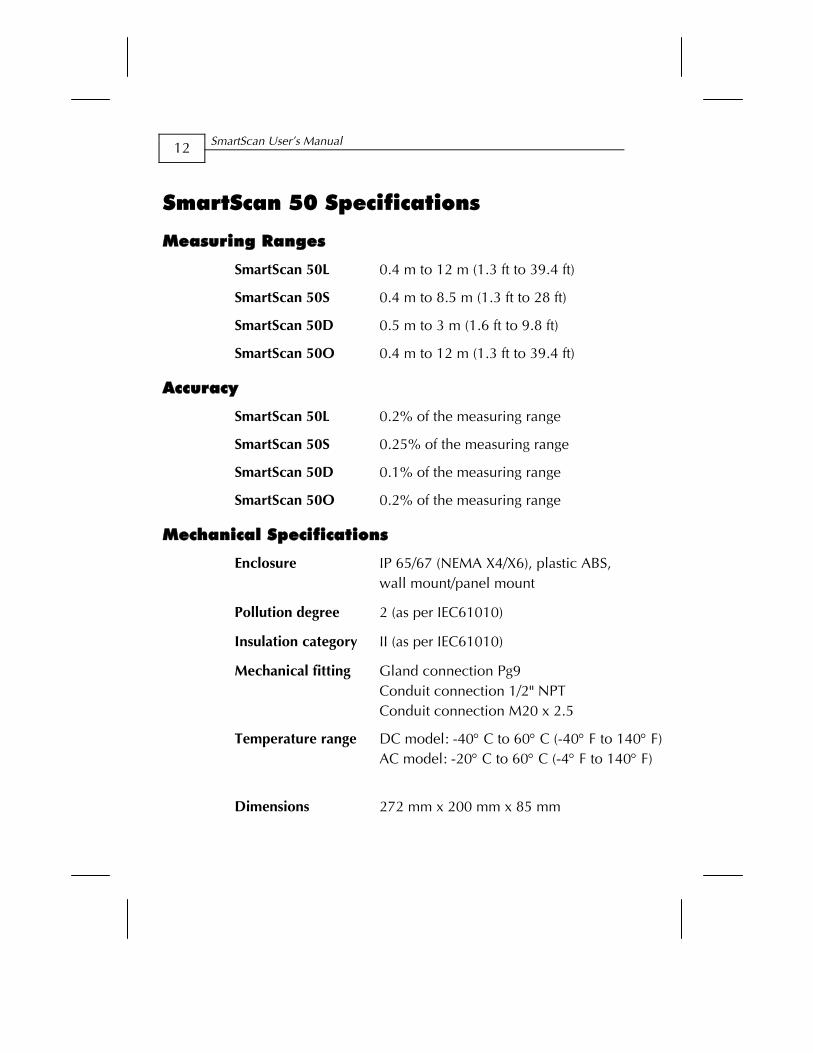
SmartScan 50 Specifications
Measuring Ranges
SmartScan 50L 0.4 m to 12 m (1.3 ft to 39.4 ft)
SmartScan 50S 0.4 m to 8.5 m (1.3 ft to 28 ft)
SmartScan 50D 0.5 m to 3 m (1.6 ft to 9.8 ft)
SmartScan 50O 0.4 m to 12 m (1.3 ft to 39.4 ft)
Accuracy
SmartScan 50L 0.2% of the measuring range
SmartScan 50S 0.25% of the measuring range
SmartScan 50D 0.1% of the measuring range
SmartScan 50O 0.2% of the measuring range
Mechanical Specifications
Enclosure IP 65/67 (NEMA X4/X6), plastic ABS, wall mount/panel mount
Pollution degree 2 (as per IEC61010)
Insulation category II (as per IEC61010)
Mechanical fitting Gland connection Pg9 Conduit connection 1/2" NPT Conduit connection M20 x 2.5
Temperature range DC model: -40° C to 60° C (-40° F to 140° F)AC model: -20° C to 60° C (-4° F to 140° F)
Dimensions 272 mm x 200 mm x 85 mm
Introducing SmartScan CHAPTER 1
13
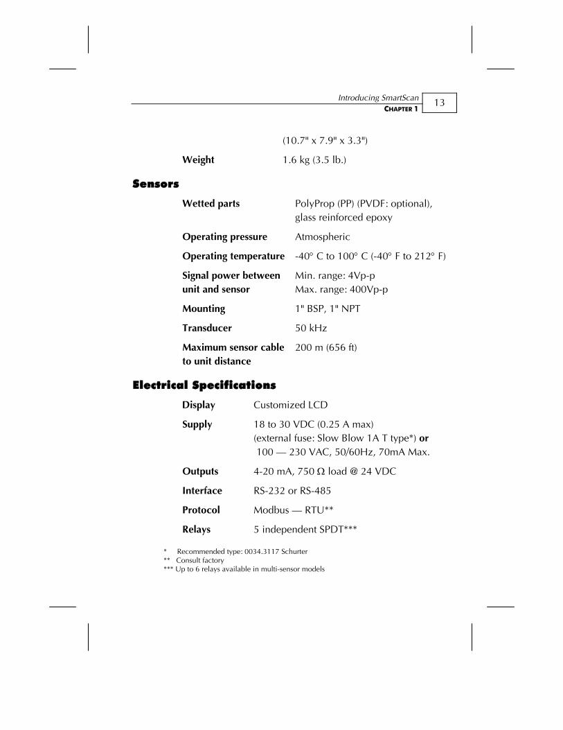
(10.7" x 7.9" x 3.3")
Weight 1.6 kg (3.5 lb.)
Sensors
Wetted parts PolyProp (PP) (PVDF: optional), glass reinforced epoxy
Operating pressure Atmospheric
Operating temperature
Signal power between unit and sensor
-40° C to 100° C (-40° F to 212° F)
Min. range: 4Vp-p Max. range: 400Vp-p
Mounting 1" BSP, 1" NPT
Transducer 50 kHz
Maximum sensor cable to unit distance
200 m (656 ft)
Electrical Specifications
Display Customized LCD
Supply 18 to 30 VDC (0.25 A max) (external fuse: Slow Blow 1A T type*) or 100 — 230 VAC, 50/60Hz, 70mA Max.
Outputs 4-20 mA, 750 Ω load @ 24 VDC
Interface RS-232 or RS-485
Protocol Modbus — RTU**
Relays 5 independent SPDT***
* Recommended type: 0034.3117 Schurter ** Consult factory *** Up to 6 relays available in multi-sensor models

SmartScan User’s Manual
14
Certifications CE - EMC, FM — Safety, FCC
Transmitter: FM, (Classified): Non Incendive, Class I,II,III/ Division 2/ Groups ABCDFG/T4
Sensor: 3A, *EEx m IIC T5
Characteristics
Level, distance, flow, volume, kilograms, totalization and diameter.
Introducing SmartScan CHAPTER 1
15
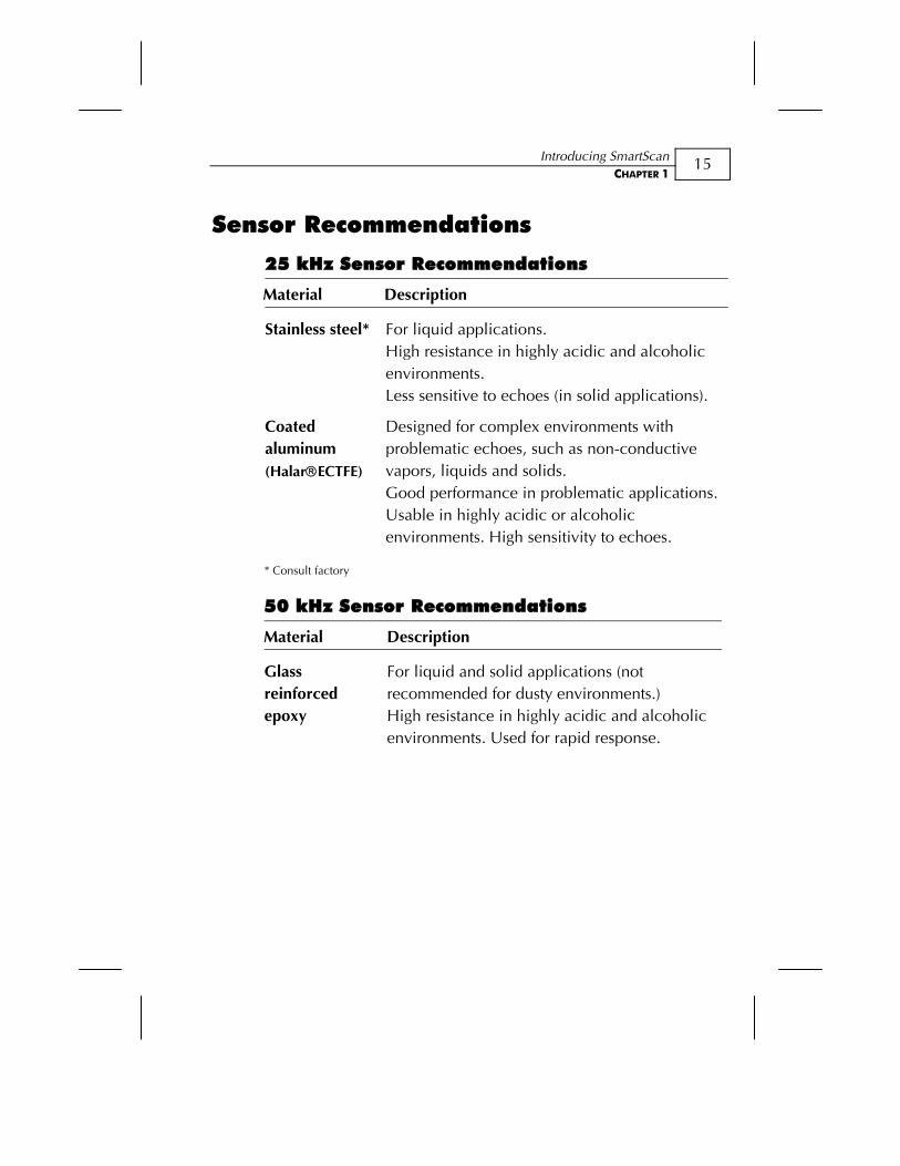
Sensor Recommendations
25 kHz Sensor Recommendations
Material Description
Stainless steel* For liquid applications. High resistance in highly acidic and alcoholic environments. Less sensitive to echoes (in solid applications).
Coated aluminum (Halar®ECTFE)
Designed for complex environments with problematic echoes, such as non-conductive vapors, liquids and solids. Good performance in problematic applications. Usable in highly acidic or alcoholic environments. High sensitivity to echoes.
* Consult factory
50 kHz Sensor Recommendations
Material Description
Glass reinforced epoxy
For liquid and solid applications (not recommended for dusty environments.) High resistance in highly acidic and alcoholic environments. Used for rapid response.
SmartScan User’s Manual
16
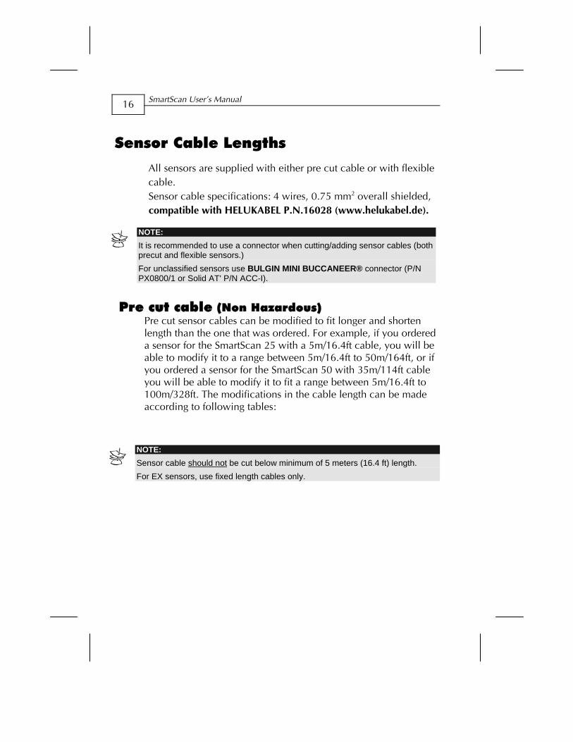
Sensor Cable Lengths
All sensors are supplied with either pre cut cable or with flexible cable. Sensor cable specifications: 4 wires, 0.75 mm2 overall shielded, compatible with HELUKABEL P.N.16028 (www.helukabel.de).
NOTE: It is recommended to use a connector when cutting/adding sensor cables (both precut and flexible sensors.) For unclassified sensors use BULGIN MINI BUCCANEER® connector (P/N PX0800/1 or Solid AT' P/N ACC-I).
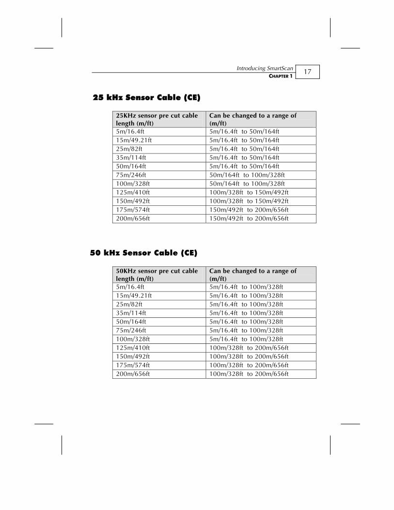
Pre cut cable (Non Hazardous)
Pre cut sensor cables can be modified to fit longer and shorten length than the one that was ordered. For example, if you ordered a sensor for the SmartScan 25 with a 5m/16.4ft cable, you will be able to modify it to a range between 5m/16.4ft to 50m/164ft, or if you ordered a sensor for the SmartScan 50 with 35m/114ft cable you will be able to modify it to fit a range between 5m/16.4ft to 100m/328ft. The modifications in the cable length can be made according to following tables:
NOTE:
Sensor cable should not be cut below minimum of 5 meters (16.4 ft) length. For EX sensors, use fixed length cables only.
Introducing SmartScan CHAPTER 1
17
25 kHz Sensor Cable (CE)
25KHz sensor pre cut cable length (m/ft)
Can be changed to a range of (m/ft)
5m/16.4ft 5m/16.4ft to 50m/164ft 15m/49.21ft 5m/16.4ft to 50m/164ft 25m/82ft 5m/16.4ft to 50m/164ft 35m/114ft 5m/16.4ft to 50m/164ft 50m/164ft 5m/16.4ft to 50m/164ft 75m/246ft 50m/164ft to 100m/328ft 100m/328ft 50m/164ft to 100m/328ft 125m/410ft 100m/328ft to 150m/492ft 150m/492ft 100m/328ft to 150m/492ft 175m/574ft 150m/492ft to 200m/656ft 200m/656ft 150m/492ft to 200m/656ft
50 kHz Sensor Cable (CE)
50KHz sensor pre cut cable length (m/ft)
Can be changed to a range of (m/ft)
5m/16.4ft 5m/16.4ft to 100m/328ft 15m/49.21ft 5m/16.4ft to 100m/328ft 25m/82ft 5m/16.4ft to 100m/328ft 35m/114ft 5m/16.4ft to 100m/328ft 50m/164ft 5m/16.4ft to 100m/328ft 75m/246ft 5m/16.4ft to 100m/328ft 100m/328ft 5m/16.4ft to 100m/328ft 125m/410ft 100m/328ft to 200m/656ft 150m/492ft 100m/328ft to 200m/656ft 175m/574ft 100m/328ft to 200m/656ft 200m/656ft 100m/328ft to 200m/656ft
SmartScan User’s Manual
18
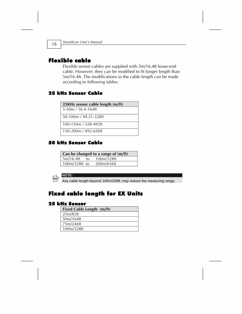
Flexible cable Flexible sensor cables are supplied with 5m/16.4ft loose-end cable. However, they can be modified to fit longer length than 5m/16.4ft. The modifications in the cable length can be made according to following tables:
25 kHz Sensor Cable
25KHz sensor cable length (m/ft) 5-50m / 16.4-164ft
50-100m / 49.21-328ft
100-150m / 328-492ft
150-200m / 492-656ft
50 kHz Sensor Cable
Can be changed to a range of (m/ft) 5m/16.4ft to 100m/328ft 100m/328ft to 200m/656ft
NOTE: Any cable length beyond 100m/328ft, may reduce the measuring range.
Fixed cable length for EX Units
25 kHz Sensor Fixed Cable Length (m/ft) 25m/82ft 50m/164ft 75m/246ft 100m/328ft
Installing SmartScan CHAPTER 2
19
Chapter 2
Installing SmartScan
Precautions Ensure that the SmartScan components are mounted in an area
that meets the stated temperature, pressure and technical specifications.
Ensure that high-voltage sources or cables are at least 1 m/3.28ft away from the sensor and its cable.
Use round cables with minimum diameter of 6-7 mm to ensure that the unit remains sealed (IP65/67).
Ensure that cables are routed correctly and tightened along walls or pipes.
Ensure that all cables are overall shielded (sensor cable, interface cable, power cable and current cable).
Installation and operation of this product should be performed, according to the Product User Manual and Product Certification. Otherwise the use of this product is prohibited.
SmartScan User’s Manual
20
Installing the SmartScan Sensor The following procedures describe sensor installation using 1" or 2" threading and a correlating locking nut. The installation procedure is the same whether the sensor is mounted directly on the tank or mounted on a pipe.
NOTE: If applicable, you can also install the sensor by screwing it directly into the tank or pipe threading. Ensure that the tank/pipe threading matches the sensor threads.
To install the sensor using 1" threading:
1 Open the required tank (or pipe).
2 Feed the free end of the sensor cable from the inside of the tank through the aperture at the top of the tank, until the sensor is pulled taut against the ceiling. The threaded end of the sensor should protrude from the top of the tank.
3 Spread silicon grease around the threading to seal against leakage (you can also use a Teflon band).
4 Thread the free end of the sensor cable through a 1" locking nut (not supplied with the SmartScan unit). Bolt the sensor into place by securing the nut to the sensor thread protruding from the top of the tank.
NOTE: Tighten the nut by hand only. When tightening the nut, hold the lower part of the sensor.
5 Wire the sensor cable to the main SmartScan unit, as described on page 29.
Installing SmartScan CHAPTER 2
21
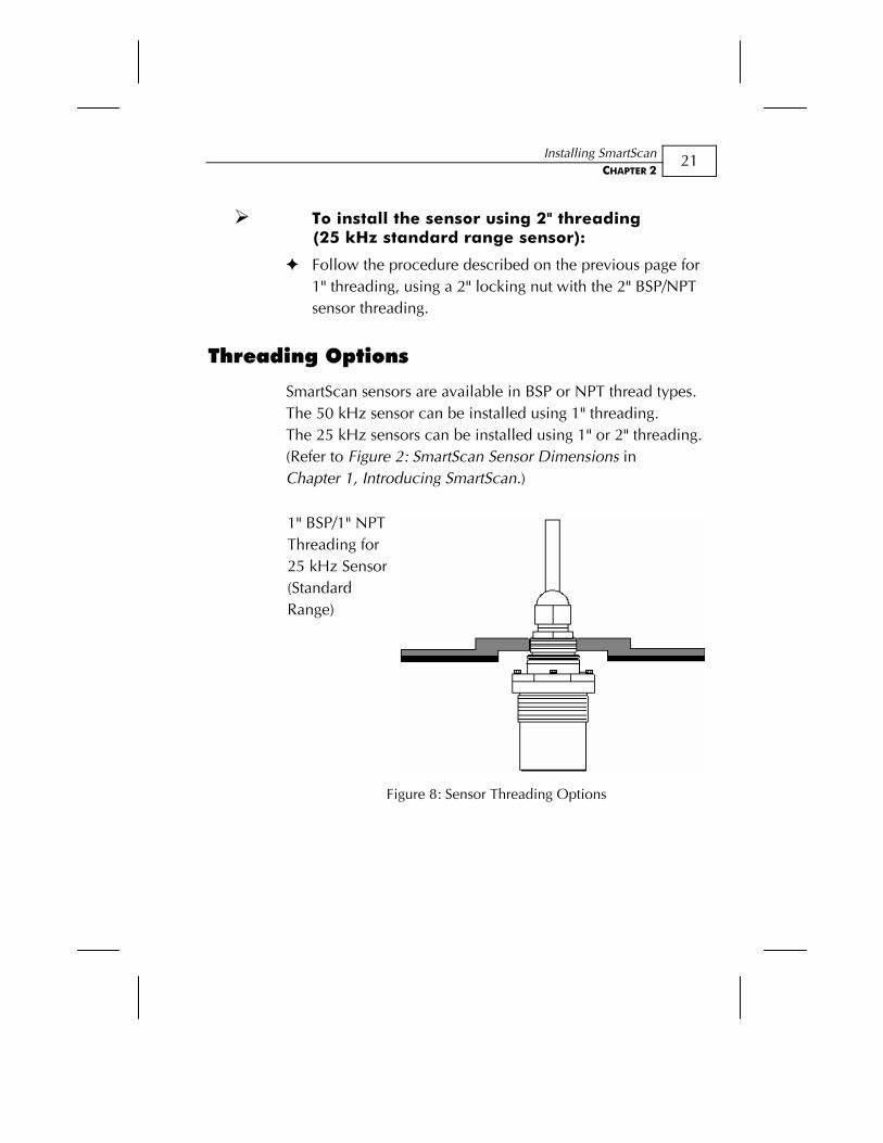
To install the sensor using 2" threading (25 kHz standard range sensor):
Follow the procedure described on the previous page for 1" threading, using a 2" locking nut with the 2" BSP/NPT sensor threading.
Threading Options
SmartScan sensors are available in BSP or NPT thread types. The 50 kHz sensor can be installed using 1" threading. The 25 kHz sensors can be installed using 1" or 2" threading. (Refer to Figure 2: SmartScan Sensor Dimensions in Chapter 1, Introducing SmartScan.)
1" BSP/1" NPT Threading for 25 kHz Sensor (Standard Range)
Figure 8: Sensor Threading Options
SmartScan User’s Manual
22
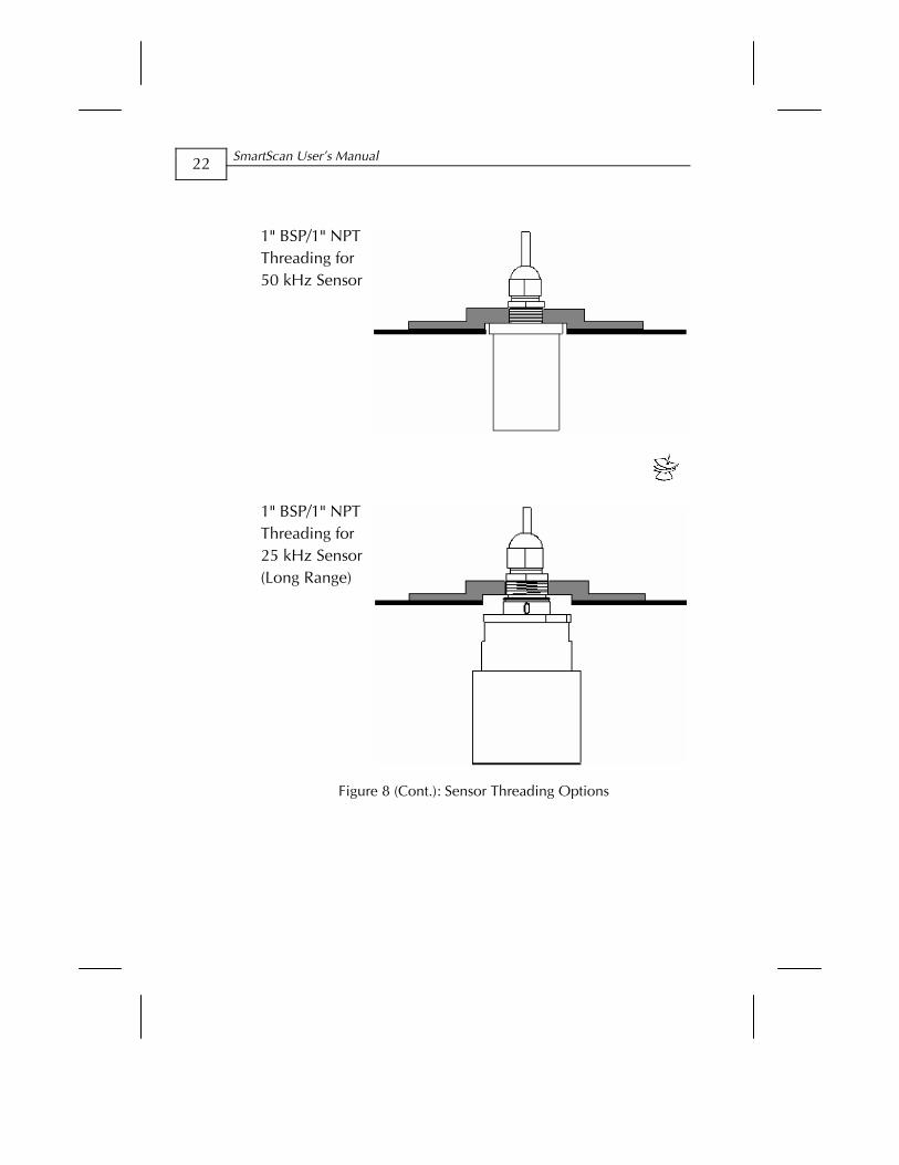
1" BSP/1" NPT Threading for 50 kHz Sensor
1" BSP/1" NPT Threading for 25 kHz Sensor (Long Range)
Figure 8 (Cont.): Sensor Threading Options
Installing SmartScan CHAPTER 2
23
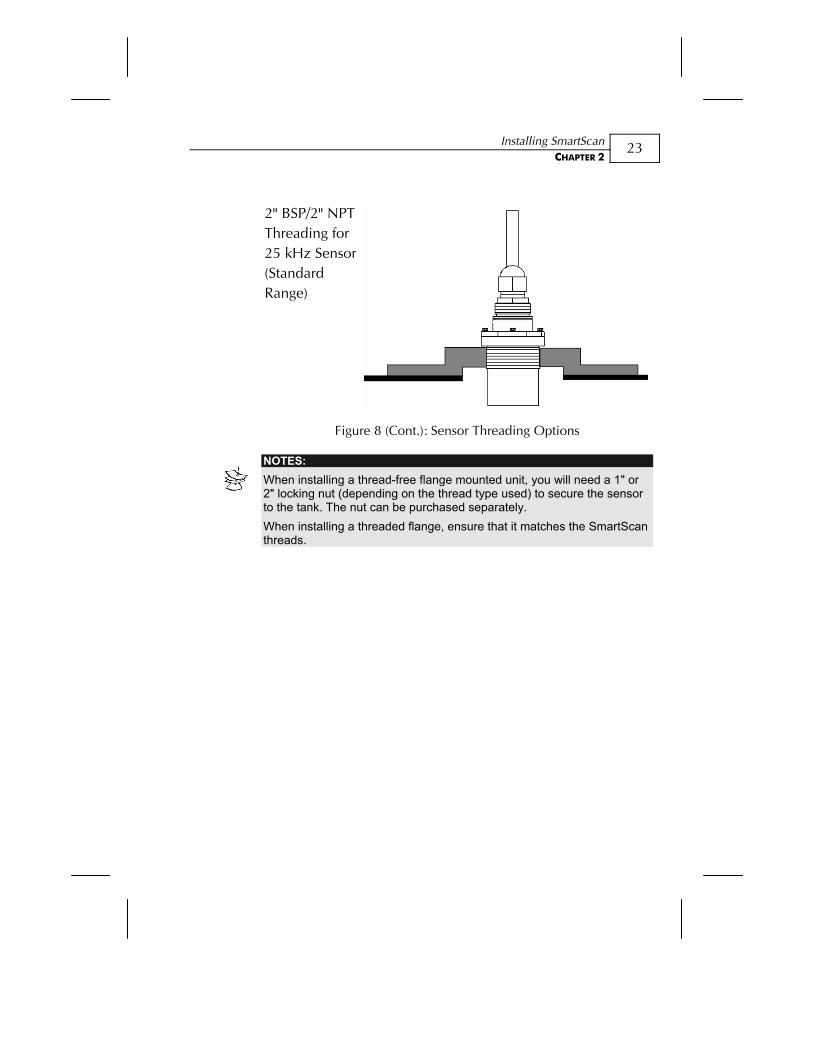
2" BSP/2" NPT Threading for 25 kHz Sensor (Standard Range)
Figure 8 (Cont.): Sensor Threading Options
NOTES: When installing a thread-free flange mounted unit, you will need a 1" or 2" locking nut (depending on the thread type used) to secure the sensor to the tank. The nut can be purchased separately. When installing a threaded flange, ensure that it matches the SmartScan threads.
SmartScan User’s Manual
24
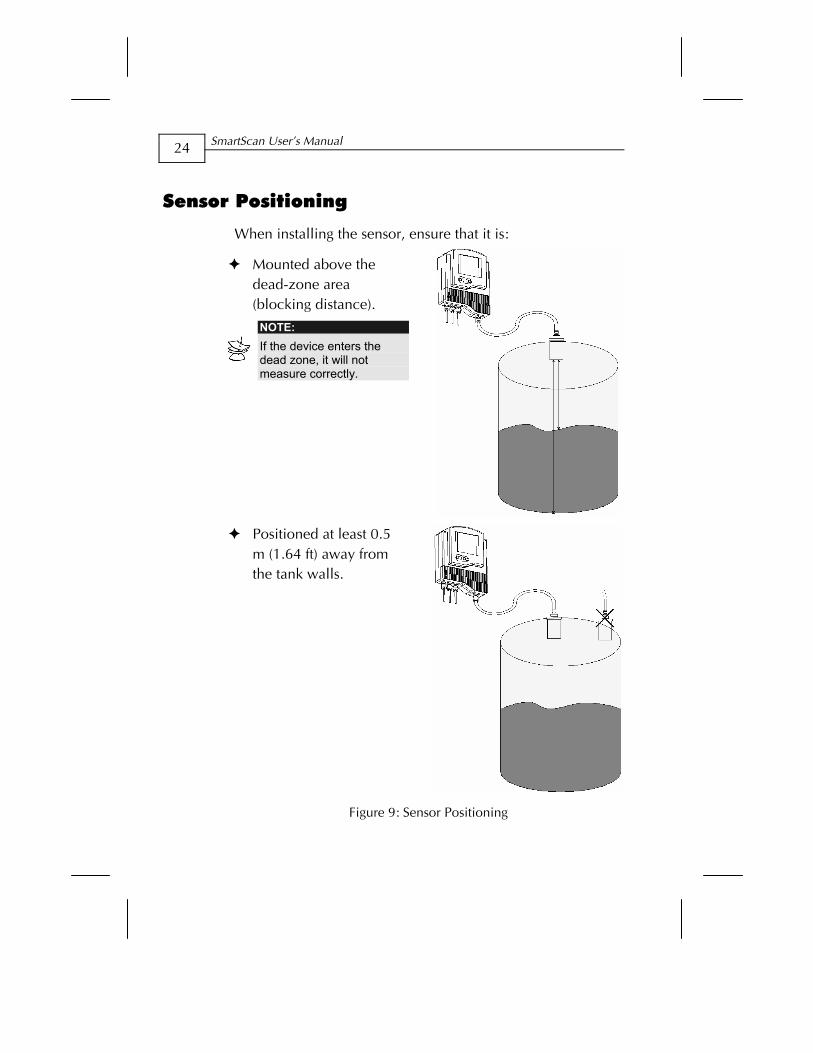
Sensor Positioning
When installing the sensor, ensure that it is:
Mounted above the dead-zone area (blocking distance).
NOTE: If the device enters the dead zone, it will not measure correctly.
Positioned at least 0.5
m (1.64 ft) away from the tank walls.
Figure 9: Sensor Positioning
Installing SmartScan CHAPTER 2
25
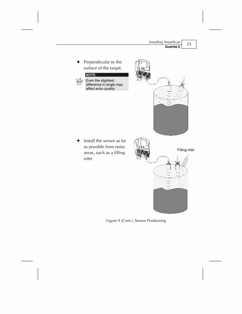
Perpendicular to the surface of the target.
NOTE: Even the slightest difference in angle may affect echo quality.
Install the sensor as far
as possible from noisy areas, such as a filling inlet.
Figure 9 (Cont.): Sensor Positioning
Filling inlet
SmartScan User’s Manual
26
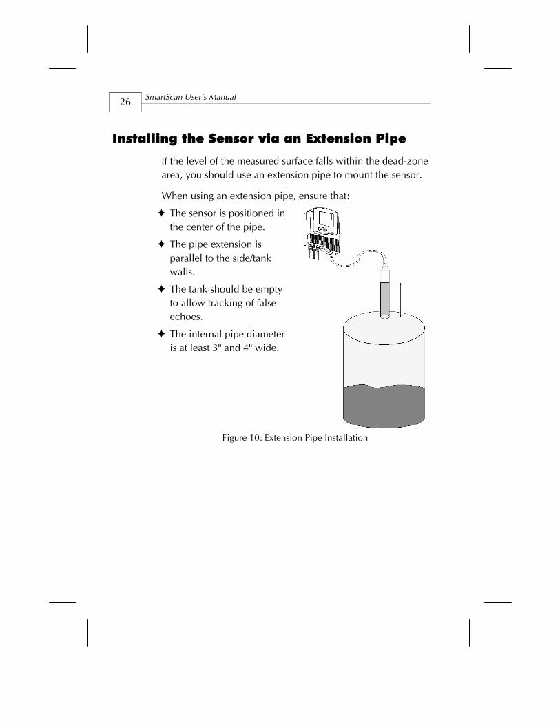
Installing the Sensor via an Extension Pipe
If the level of the measured surface falls within the dead-zone area, you should use an extension pipe to mount the sensor.
When using an extension pipe, ensure that:
The sensor is positioned in the center of the pipe.
The pipe extension is parallel to the side/tank walls.
The tank should be empty to allow tracking of false echoes.
The internal pipe diameter is at least 3" and 4" wide.
Figure 10: Extension Pipe Installation
Installing SmartScan CHAPTER 2
27
When installing the sensor with an extension pipe, follow these specifications:
25 kHz and 50 kHz Sensor
Pipe Length Internal Pipe Diameter
0.50 m (1.64 ft) 3"/4"
NOTES: We advise you to consult with your local distributor prior to the installation. It is essential to run scan distance function during the installation process. It is recommended to use pipes made of PVC/Plastic and not Stainless Steel.
SmartScan User’s Manual
28
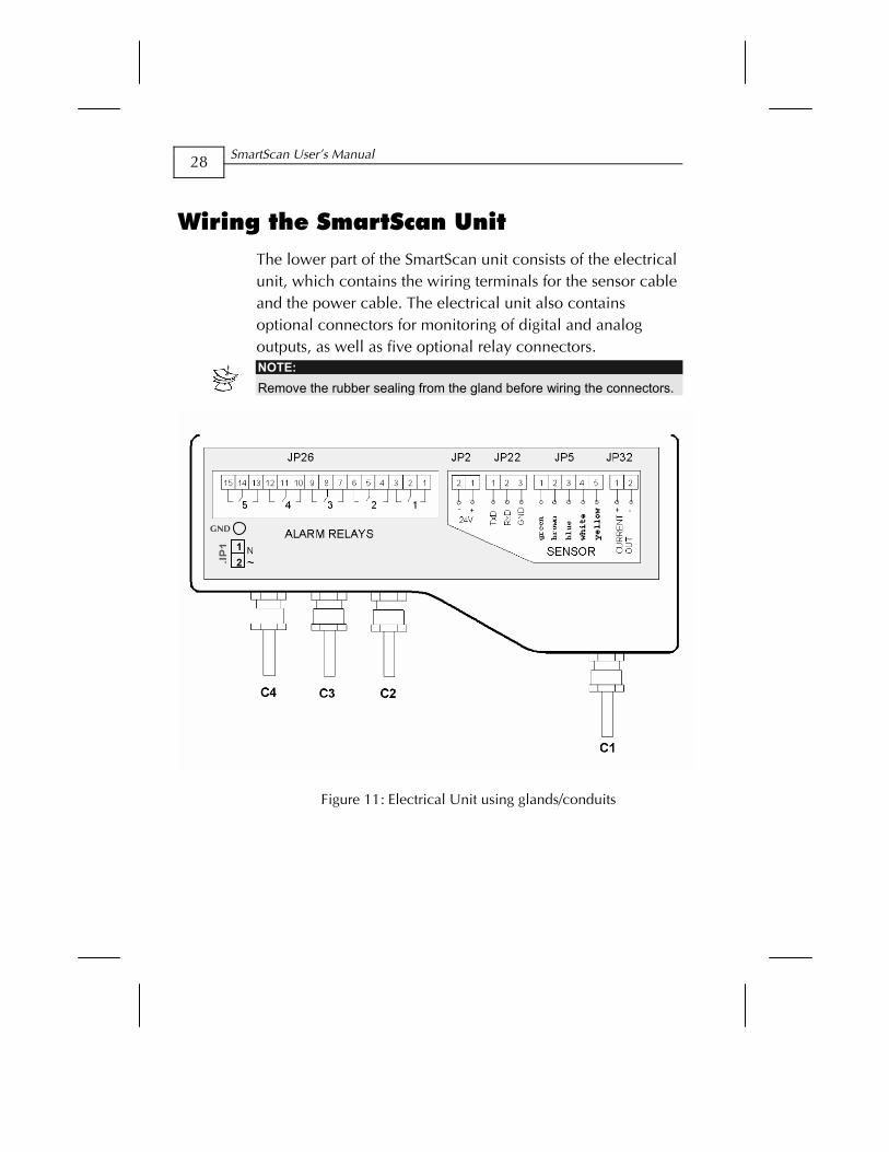
Wiring the SmartScan Unit The lower part of the SmartScan unit consists of the electrical unit, which contains the wiring terminals for the sensor cable and the power cable. The electrical unit also contains optional connectors for monitoring of digital and analog outputs, as well as five optional relay connectors.
NOTE: Remove the rubber sealing from the gland before wiring the connectors.
Figure 11: Electrical Unit using glands/conduits
JP1
2 1
GND
Installing SmartScan CHAPTER 2
29
In order to make a wiring connection, remove the ribbed faceplate covering the electrical unit using a 3-mm Allen wrench. Ensure that the cover is replaced securely after all wiring connections are completed.
To wire and install the SmartScan:
1 Install the sensor, as described in Installing the SmartScan Sensor, page 20.
2 Route the sensor’s cable (C1) from the sensor to the main unit location. Choose a route without electromagnetic interference (electrical engines, pumps or high voltage
3 Wire the sensor’s cable (C1) to the main unit, as described in Wiring for the Sensor Cable, below.
4 Make any optional monitoring or relay cable connections to the main unit, as described on pages 31 and 32.
5 Connect the power cable to the main unit, as described on page 33.
6 If required, mount the main unit on the wall using the optional wall-mount plate.
Wiring the Sensor Cable
Sensor cable specifications: 4 wires, 0.75 mm2 overall shielded, and compatible to HELUKABEL P.N.16028.
After the sensor is installed on the tank, the free end of the sensor cable is connected to the electrical unit using terminal JP5.
SmartScan User’s Manual
30
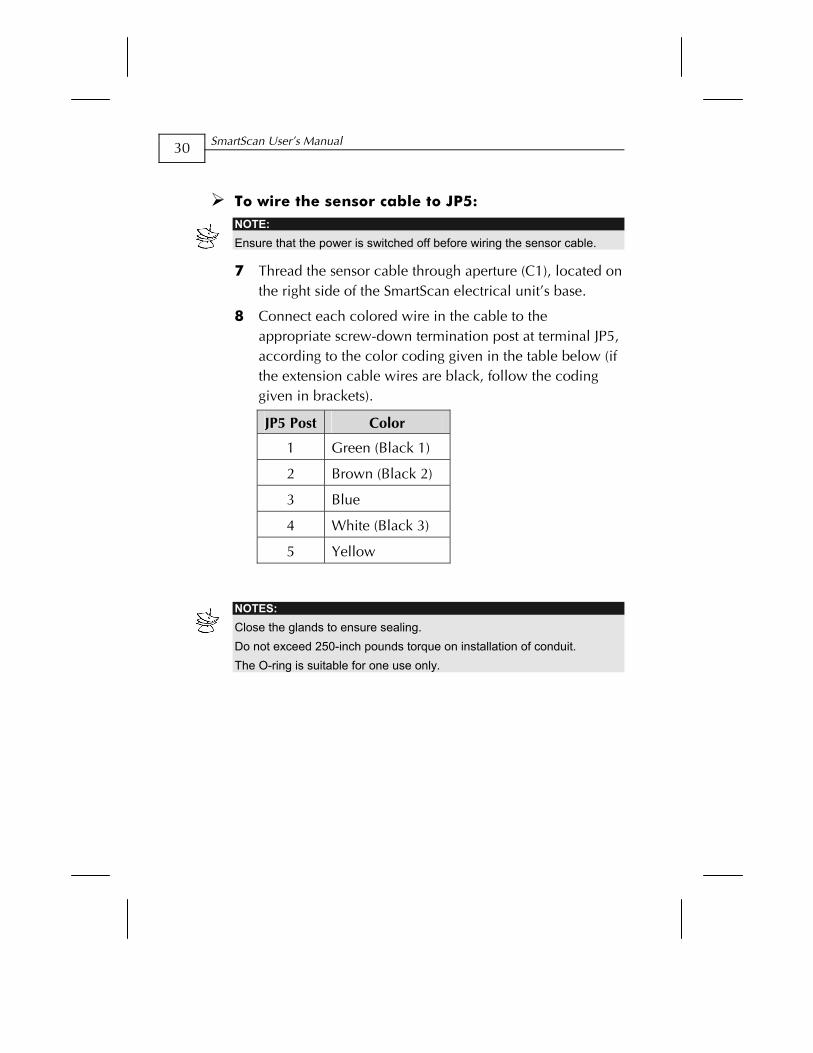
To wire the sensor cable to JP5:
NOTE: Ensure that the power is switched off before wiring the sensor cable.
7 Thread the sensor cable through aperture (C1), located on the right side of the SmartScan electrical unit’s base.
8 Connect each colored wire in the cable to the appropriate screw-down termination post at terminal JP5, according to the color coding given in the table below (if the extension cable wires are black, follow the coding given in brackets).
JP5 Post Color
1 Green (Black 1)
2 Brown (Black 2)
3 Blue
4 White (Black 3)
5 Yellow
NOTES: Close the glands to ensure sealing. Do not exceed 250-inch pounds torque on installation of conduit. The O-ring is suitable for one use only.
Installing SmartScan CHAPTER 2
31
Wiring the Monitoring Cables
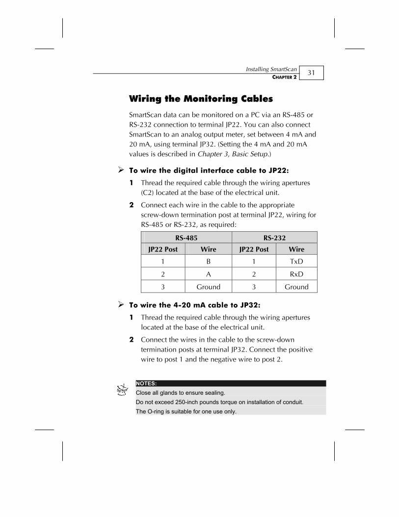
SmartScan data can be monitored on a PC via an RS-485 or RS-232 connection to terminal JP22. You can also connect SmartScan to an analog output meter, set between 4 mA and 20 mA, using terminal JP32. (Setting the 4 mA and 20 mA values is described in Chapter 3, Basic Setup.)
To wire the digital interface cable to JP22:
1 Thread the required cable through the wiring apertures (C2) located at the base of the electrical unit.
2 Connect each wire in the cable to the appropriate screw-down termination post at terminal JP22, wiring for RS-485 or RS-232, as required:
RS-485 RS-232
JP22 Post Wire JP22 Post Wire
1 B 1 TxD
2 A 2 RxD
3 Ground 3 Ground
To wire the 4-20 mA cable to JP32:
1 Thread the required cable through the wiring apertures located at the base of the electrical unit.
2 Connect the wires in the cable to the screw-down termination posts at terminal JP32. Connect the positive wire to post 1 and the negative wire to post 2.
NOTES: Close all glands to ensure sealing. Do not exceed 250-inch pounds torque on installation of conduit. The O-ring is suitable for one use only.
SmartScan User’s Manual
32
Wiring the Relays Cable
SmartScan’s electrical unit provides connectors at terminal JP26 for up to five independently programmable relays. The relays can be used to initiate certain actions, such as controlling pumps, triggering an alarm or sending a warning message, when a defined value is reached. (Defining values for the relays is described in Chapter 3, Basic Setup.)
To wire the relays cable to JP26 using VDC power:
1 Thread the required cable through apertures (C2/C3) located at the base of the electrical unit.
2 Connect the relay cable wires to the appropriate posts, as shown in Figure 11: Electrical Unit, page 28.
To wire the relays cable to JP26 using VAC power:
1 Thread the required cable through apertures (C3/C4) located at the base of the electrical unit.
2 Connect the relay cable wires to the appropriate posts, as shown in Figure 11: Electrical Unit, page 28.
NOTES: Close the glands to ensure sealing. The O-ring is suitable for one use only. If your unit is equipped with conduits instead of glands, aperture C3 is not available. Use aperture C4 instead. Do not exceed 250-inch pounds torque on installation of conduit.
Installing SmartScan CHAPTER 2
33
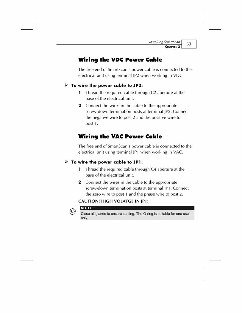
Wiring the VDC Power Cable
The free end of SmartScan’s power cable is connected to the electrical unit using terminal JP2 when working in VDC.
To wire the power cable to JP2:
1 Thread the required cable through C2 aperture at the base of the electrical unit.
2 Connect the wires in the cable to the appropriate screw-down termination posts at terminal JP2. Connect the negative wire to post 2 and the positive wire to post 1.
Wiring the VAC Power Cable
The free end of SmartScan’s power cable is connected to the electrical unit using terminal JP1 when working in VAC.
To wire the power cable to JP1:
1 Thread the required cable through C4 aperture at the base of the electrical unit.
2 Connect the wires in the cable to the appropriate screw-down termination posts at terminal JP1. Connect the zero wire to post 1 and the phase wire to post 2.
CAUTION! HIGH VOLATGE IN JP1!
NOTES: Close all glands to ensure sealing. The O-ring is suitable for one use only.
SmartScan User’s Manual
34
SmartScan 25 Unit - Intrinsically Safe Connections
Hazardous Area Installation
(For Ex version)
Installation of the equipment shall be in accordance with the NEC Articles 504 and 505 and ISA RP 12.06.01 Recommended Practice for the Installation of Intrinsically Safe Circuits.
Instructions specific to hazardous area installation.
(Reference European ATEX Directive 94/9/EC, Annex II, 1.0.6.)
The following instructions apply to equipment covered by certificate number Sira 03ATEX2518X:
The equipment may be used in a hazardous area with flammable gases and vapors with apparatus groups IIC, IIB and IIA and with temperature classes T1, T2, T3, T4.
The equipment is certified for use in ambient temperatures in the range of -40oC to +70oC and should not be used outside this range.
Installation shall be carried out in accordance with the applicable code of practice by suitably trained personnel.
The equipment is not intended to be repaired by the user. Repair of this equipment shall be carried out by the manufacturer in accordance with the applicable code of practice.
If the equipment is likely to come into contact with aggressive substances, then it is the responsibility of the user to take suitable precautions that prevent it from
Installing SmartScan CHAPTER 2
35
being adversely affected, thus ensuring that the type of protection is not compromised.
The certificate number has an ’X’ suffix that indicates that the following special condition of certification applies;
The supplies from the two intrinsically safe barriers must be prevented from combining with each other in the supply cable by using separate cables or a cable with a screen around each circuit.
Aggressive Substances - e.g. acidic liquids or gases that may attack metals or solvents that may affect polymeric materials.
Suitable Precautions - e.g. regular checks as part of routine inspections or establishing from the material’s data sheet that it is resistant to specific chemicals.
The manufacturer should note that, on being put into service, the equipment must be accompanied by a translation of the instructions in the language or languages of the country in which the equipment is to be used and by the instructions in the original language.
The instructions shall contain the certification marking as detailed on the relevant certification drawing; number DD-SN25Ex-labels.
SmartScan User’s Manual
36
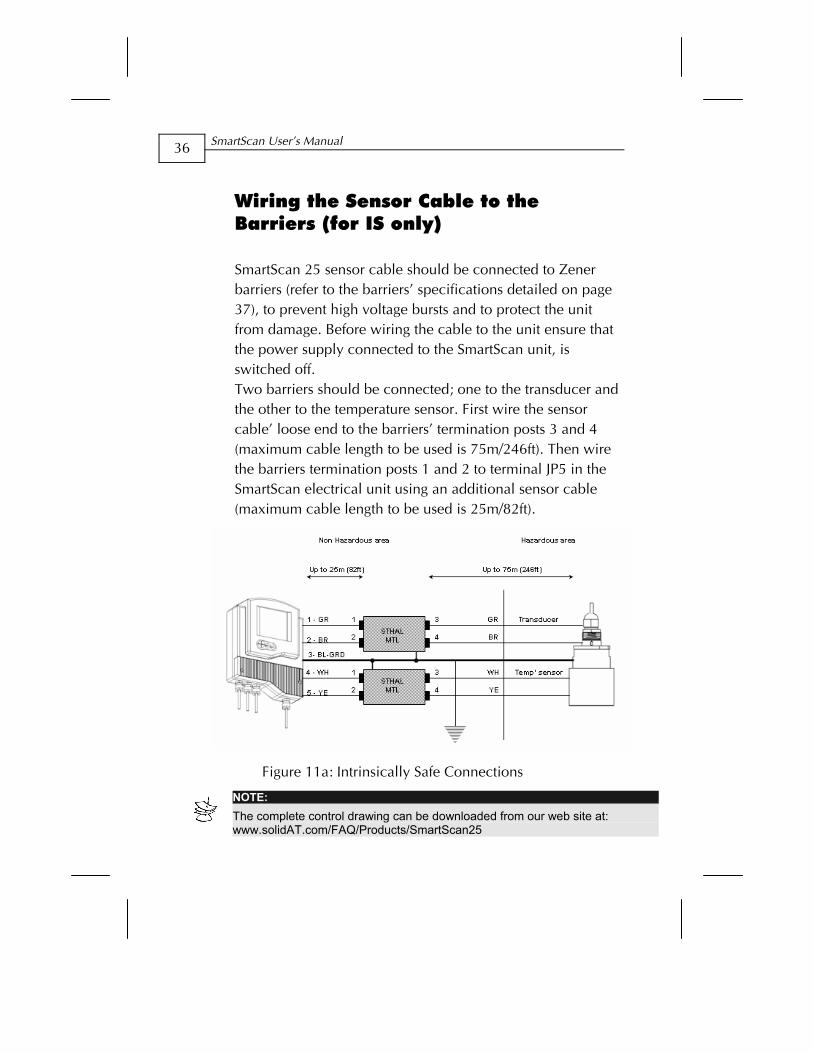
Wiring the Sensor Cable to the Barriers (for IS only)
SmartScan 25 sensor cable should be connected to Zener barriers (refer to the barriers’ specifications detailed on page 37), to prevent high voltage bursts and to protect the unit from damage. Before wiring the cable to the unit ensure that the power supply connected to the SmartScan unit, is switched off. Two barriers should be connected; one to the transducer and the other to the temperature sensor. First wire the sensor cable’ loose end to the barriers’ termination posts 3 and 4 (maximum cable length to be used is 75m/246ft). Then wire the barriers termination posts 1 and 2 to terminal JP5 in the SmartScan electrical unit using an additional sensor cable (maximum cable length to be used is 25m/82ft).
Figure 11a: Intrinsically Safe Connections
NOTE: The complete control drawing can be downloaded from our web site at: www.solidAT.com/FAQ/Products/SmartScan25
Installing SmartScan CHAPTER 2
37
Wiring the Transducer to the Barriers
To wire the sensor cable to the transducer barrier:
1 Screw-down the sensor’s green (GR) wire to the barrier’s termination post (3).
2 Screw-down the sensor’s brown (BR) wire to the barrier’s termination post (4).
To wire the sensor cable to the temperature sensor barrier:
1 Screw-down the sensor’s white (WH) wire to the barrier’s termination post (3).
2 Screw-down the sensor’s yellow (YE) wire to the barrier’s termination post (4).
NOTE: The sensor's blue (BL) wire is for ground purposes and should be attached to the barrier's chassis.
Wiring the Barriers to the SmartScan Unit
To wire the transducer barrier to terminal JP5 in the SmartScan unit:
1 Screw-down the sensor’s green (GR) wire (1) first end to the barrier’s termination post (1) and the other end to terminal JP5 termination post (1).
2 Screw-down the sensor’s brown (BR) wire (2) first end to the barrier’s termination post (2) and the other end to terminal JP5 termination post (2).
SmartScan User’s Manual
38
To wire the temperature barrier to terminal JP5 in the SmartScan unit:
Thread the sensor cable through aperture (C1), located on the right side of the SmartScan electrical unit’s base.
1 Screw-down the sensor’s white (WH) wire (4) first end to the barrier’s termination post (1) and the other end to terminal JP5 termination post (4).
2 Screw-down the sensor’s yellow (YE) wire (5) first end to the barrier’s termination post (2) and the other end to JP5 termination post (5).
NOTES: Ensure that the SmartScan unit power is switched off before wiring the sensor cable or any other cable to the unit. The sensor's blue (BL) wire is used for ground purposes and should be screwed-down to terminal JP5 termination post (3). Sensor cable specifications: 4 wires, 0.75 mm2 overall shielded, and compatible to HELUKABLE P.N.16028. It is highly recommended to use a linear or surge power supply as your power supply. Do not exceed 250-inch pounds torque on installation of conduit. When using glands make sure that these glands are FM approved for the specific Class and Division of your installation. WARNING! Electrostatic hazard. The sensor should be cleaned with a damp cloth only!
Installing SmartScan CHAPTER 2
39
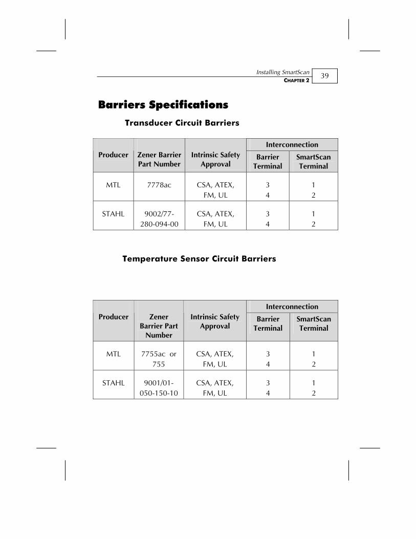
Barriers Specifications
Transducer Circuit Barriers
Temperature Sensor Circuit Barriers
Interconnection Producer Zener Barrier
Part NumberIntrinsic Safety
Approval Barrier
Terminal SmartScan Terminal
MTL 7778ac CSA, ATEX, FM, UL
3 4
1 2
STAHL 9002/77-280-094-00
CSA, ATEX, FM, UL
3 4
1 2
Interconnection Producer Zener
Barrier Part Number
Intrinsic Safety Approval
Barrier Terminal
SmartScan Terminal
MTL 7755ac or 755
CSA, ATEX, FM, UL
3 4
1 2
STAHL 9001/01-050-150-10
CSA, ATEX, FM, UL
3 4
1 2
SmartScan User’s Manual
40
Chapter 3
Basic Setup This chapter describes how to set up and calibrate SmartScan for accurate measurement monitoring using the basic menu options.
SmartScan is supplied with preprogrammed default settings, making it ready for immediate operation. Measurement readings are displayed on the default screen as soon as the unit is powered on, as described in Default Screen, page 47.
It is recommended that you replace the default tank height value with the actual tank height, as described in Setting the Tank Height, page 67. When using SmartScan, the tank height is calculated as the distance from the surface of the sensor to the bottom of the tank. You should enter this value whenever tank height is required. (For flow measurement, enter the precise flume height.)
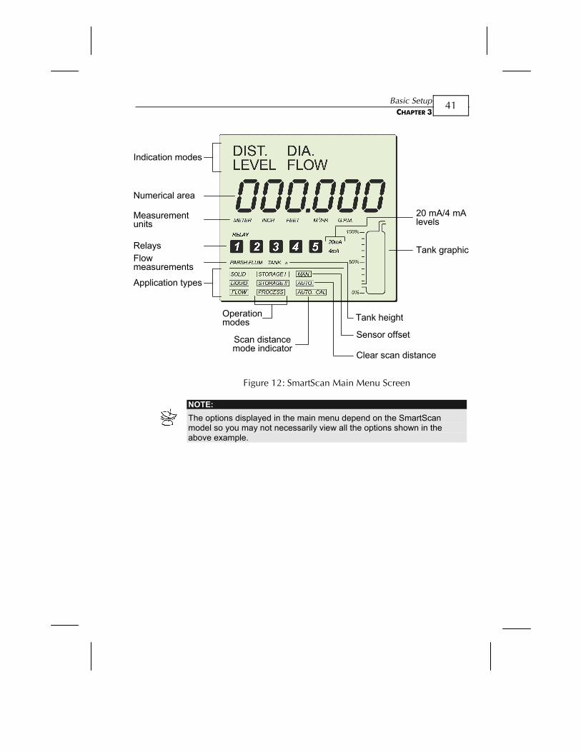
The SmartScan main menu (shown on page 41) enables you to access the primary functions for SmartScan operation, so that you can change the default settings and calibrate SmartScan, as required. You can define further specialized function options for SmartScan from the additional menu, as described in Chapter 5, Additional Features.
Basic Setup CHAPTER 3
41
Indication modes
Numerical area
Measurementunits
RelaysFlowmeasurements
Application types
20 mA/4 mAlevels
Tank graphic
Tank height
Sensor offsetScan distancemode indicator
Operationmodes
Clear scan distance
Figure 12: SmartScan Main Menu Screen
NOTE: The options displayed in the main menu depend on the SmartScan model so you may not necessarily view all the options shown in the above example.
SmartScan User’s Manual
42
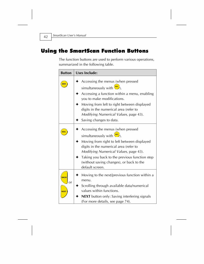
Using the SmartScan Function Buttons The function buttons are used to perform various operations, summarized in the following table.
Button Uses Include:
Accessing the menus (when pressed
simultaneously with ).
Accessing a function within a menu, enabling you to make modifications.
Moving from left to right between displayed digits in the numerical area (refer to Modifying Numerical Values, page 43).
Saving changes to data.
Accessing the menus (when pressed
simultaneously with ).
Moving from right to left between displayed digits in the numerical area (refer to Modifying Numerical Values, page 43).
Taking you back to the previous function step (without saving changes), or back to the default screen.
or
Moving to the next/previous function within a menu.
Scrolling through available data/numerical values within functions.
NEXT button only: Saving interfering signals (For more details, see page 74).
Basic Setup CHAPTER 3
43
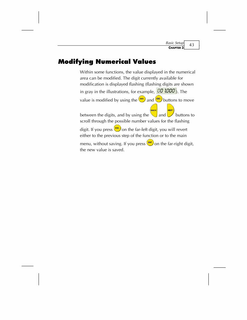
Modifying Numerical Values Within some functions, the value displayed in the numerical area can be modified. The digit currently available for modification is displayed flashing (flashing digits are shown
in gray in the illustrations, for example, ). The
value is modified by using the and buttons to move
between the digits, and by using the and buttons to scroll through the possible number values for the flashing
digit. If you press on the far-left digit, you will revert either to the previous step of the function or to the main
menu, without saving. If you press on the far-right digit, the new value is saved.
SmartScan User’s Manual
44
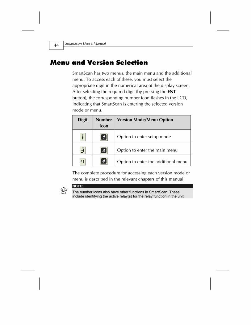
Menu and Version Selection SmartScan has two menus, the main menu and the additional menu. To access each of these, you must select the appropriate digit in the numerical area of the display screen. After selecting the required digit (by pressing the ENT button), the corresponding number icon flashes in the LCD, indicating that SmartScan is entering the selected version mode or menu.
Digit Number Icon
Version Mode/Menu Option
Option to enter setup mode
Option to enter the main menu
Option to enter the additional menu
The complete procedure for accessing each version mode or menu is described in the relevant chapters of this manual.
NOTE: The number icons also have other functions in SmartScan. These include identifying the active relay(s) for the relay function in the unit.
Basic Setup CHAPTER 3
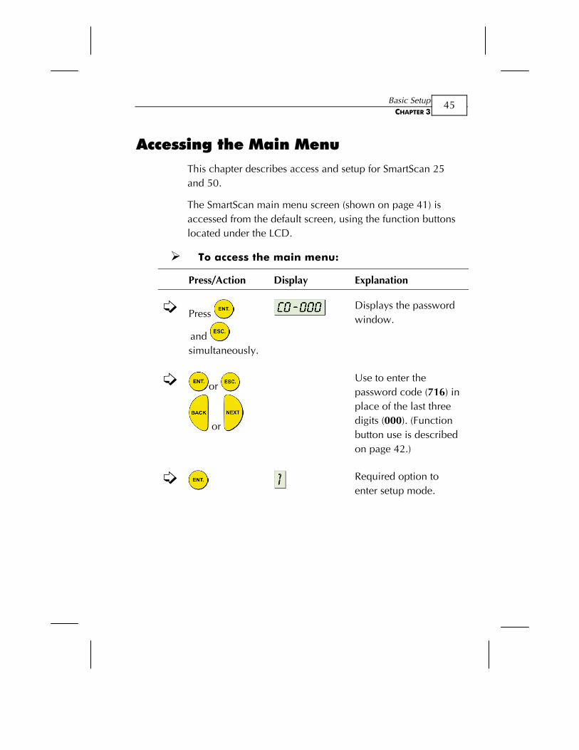
45
Accessing the Main Menu This chapter describes access and setup for SmartScan 25 and 50.
The SmartScan main menu screen (shown on page 41) is accessed from the default screen, using the function buttons located under the LCD.
To access the main menu:
Press/Action Display Explanation
Press
and
simultaneously.
Displays the password window.
or
or
Use to enter the password code (716) in place of the last three digits (000). (Function button use is described on page 42.)
Required option to enter setup mode.
SmartScan User’s Manual
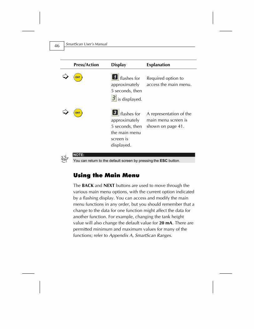
46
Press/Action Display Explanation
flashes for approximately 5 seconds, then
is displayed.
Required option to access the main menu.
flashes for approximately 5 seconds, then the main menu screen is displayed.
A representation of the main menu screen is shown on page 41.
NOTE: You can return to the default screen by pressing the ESC button.
Using the Main Menu
The BACK and NEXT buttons are used to move through the various main menu options, with the current option indicated by a flashing display. You can access and modify the main menu functions in any order, but you should remember that a change to the data for one function might affect the data for another function. For example, changing the tank height value will also change the default value for 20 mA. There are permitted minimum and maximum values for many of the functions; refer to Appendix A, SmartScan Ranges.
Basic Setup CHAPTER 3
47
The level of the tank graphic displayed in the main menu screen moves up from 0 to 100% when you save an option or when SmartScan is processing. After saving an option, the main menu is displayed with the next option flashing.
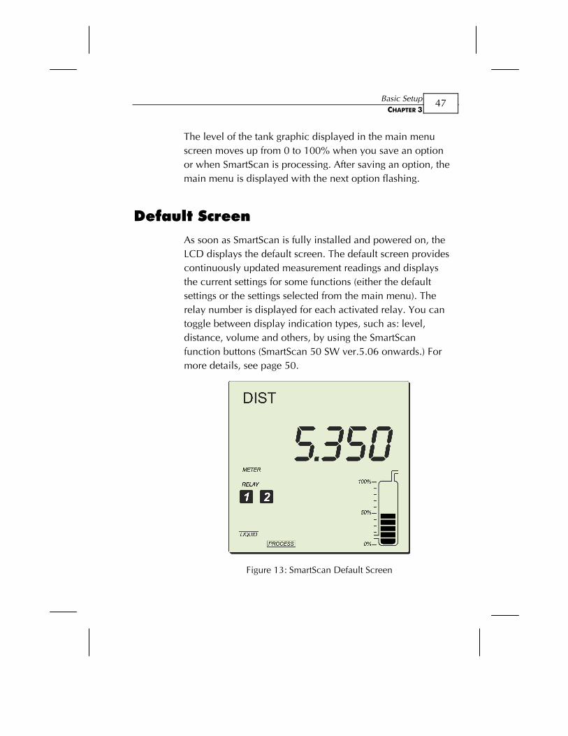
Default Screen As soon as SmartScan is fully installed and powered on, the LCD displays the default screen. The default screen provides continuously updated measurement readings and displays the current settings for some functions (either the default settings or the settings selected from the main menu). The relay number is displayed for each activated relay. You can toggle between display indication types, such as: level, distance, volume and others, by using the SmartScan function buttons (SmartScan 50 SW ver.5.06 onwards.) For more details, see page 50.
Figure 13: SmartScan Default Screen
SmartScan User’s Manual
48
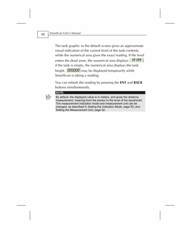
The tank graphic in the default screen gives an approximate visual indication of the current level of the tank contents, while the numerical area gives the exact reading. If the level
enters the dead zone, the numerical area displays ; if the tank is empty, the numerical area displays the tank
height. may be displayed temporarily while SmartScan is taking a reading.
You can refresh the reading by pressing the ENT and BACK buttons simultaneously.
NOTE: By default, the displayed value is in meters, and gives the distance measurement, meaning from the sensor to the level of the liquid/solid. The measurement indication mode and measurement unit can be changed, as described in Setting the Indication Mode, page 50, and Setting the Measurement Unit, page 52.
Basic Setup CHAPTER 3
49
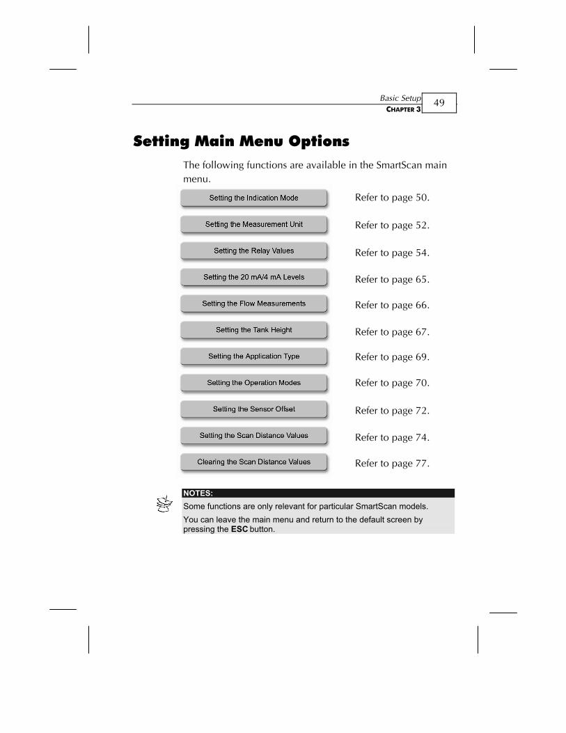
Setting Main Menu Options The following functions are available in the SmartScan main menu.
Refer to page 50.
Refer to page 52.
Refer to page 54.
Refer to page 65.
Refer to page 66.
Refer to page 67.
Refer to page 69.
Refer to page 70.
Refer to page 72.
Refer to page 74.
Refer to page 77.
NOTES: Some functions are only relevant for particular SmartScan models. You can leave the main menu and return to the default screen by pressing the ESC button.
SmartScan User’s Manual
50
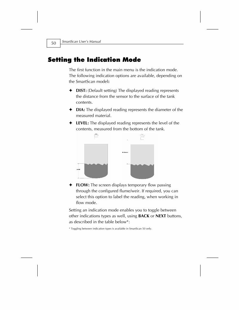
Setting the Indication Mode The first function in the main menu is the indication mode. The following indication options are available, depending on the SmartScan model:
DIST: (Default setting) The displayed reading represents the distance from the sensor to the surface of the tank contents.
DIA: The displayed reading represents the diameter of the measured material.
LEVEL: The displayed reading represents the level of the contents, measured from the bottom of the tank.
FLOW: The screen displays temporary flow passing
through the configured flume/weir. If required, you can select this option to label the reading, when working in flow mode.
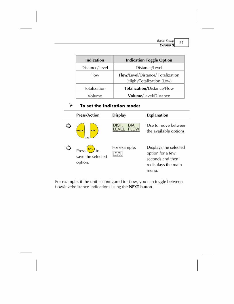
Setting an indication mode enables you to toggle between other indications types as well, using BACK or NEXT buttons, as described in the table below*: * Toggling between indication types is available in SmartScan 50 only.
Basic Setup CHAPTER 3
51
Indication Indication Toggle Option
Distance/Level Distance/Level
Flow Flow/Level/Distance/ Totalization (High)/Totalization (Low)
Totalization Totalization/Distance/Flow
Volume Volume/Level/Distance
To set the indication mode:
Press/Action Display Explanation
and
Use to move between the available options.
Press to save the selected option.
For example,
Displays the selected option for a few seconds and then redisplays the main menu.
For example, if the unit is configured for flow, you can toggle between flow/level/distance indications using the NEXT button.
SmartScan User’s Manual
52
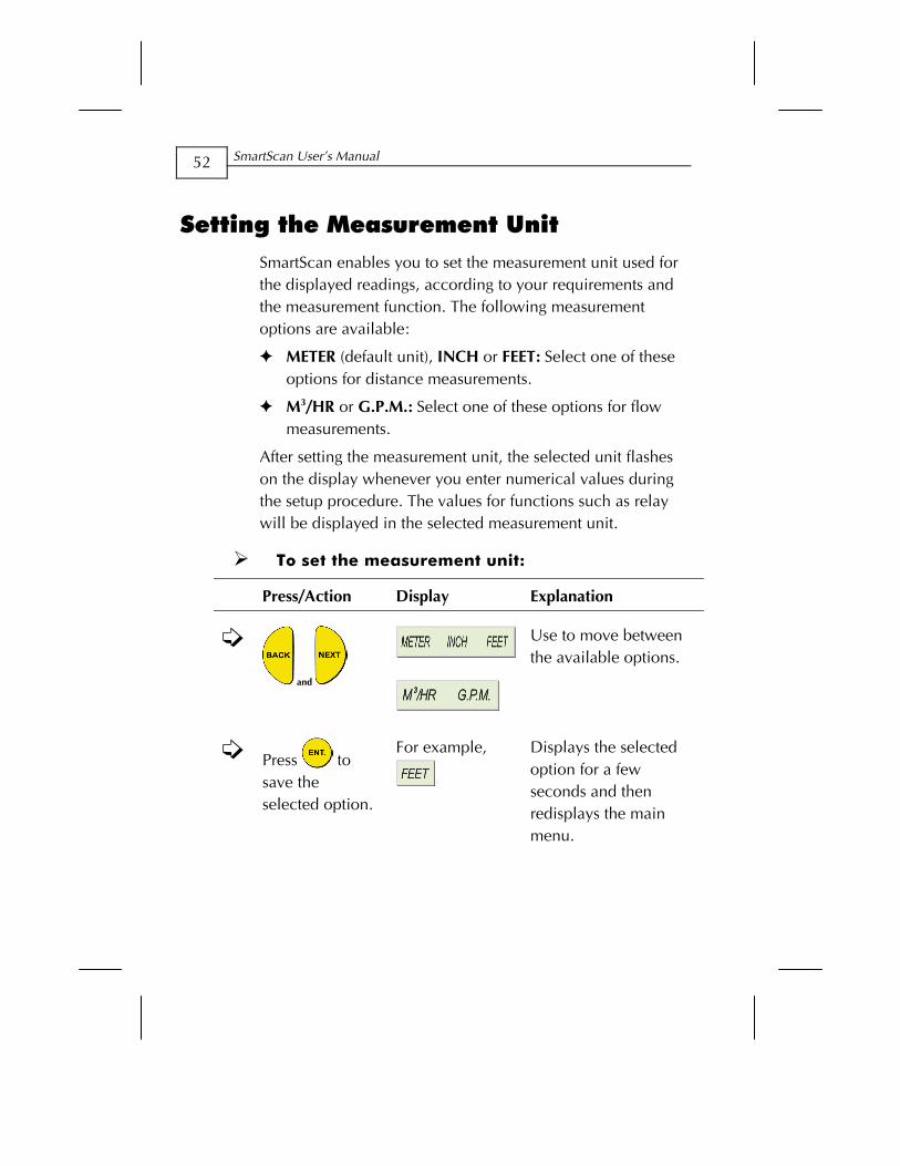
Setting the Measurement Unit SmartScan enables you to set the measurement unit used for the displayed readings, according to your requirements and the measurement function. The following measurement options are available:
METER (default unit), INCH or FEET: Select one of these options for distance measurements.
M3/HR or G.P.M.: Select one of these options for flow measurements.
After setting the measurement unit, the selected unit flashes on the display whenever you enter numerical values during the setup procedure. The values for functions such as relay will be displayed in the selected measurement unit.
To set the measurement unit:
Press/Action Display Explanation
and
Use to move between the available options.
Press to save the selected option.
For example,
Displays the selected option for a few seconds and then redisplays the main menu.
Basic Setup CHAPTER 3
53
NOTE: If you select METER, any relevant flow measurements will be in metric units, meaning M3/HR. The opposite also applies, so that if you select M3/HR, any relevant distance or level measurements will be in meters. If you select INCH or FEET, any relevant flow measurements will be in G.P.M. If you select G.P.M., any relevant distance or level measurements will be in inches. In case you select METER when using a FLOW model configured to show G.P.M, the METER sign will flash rapidly for few seconds. If you approve the selection by pressing ENT. the flow measurement units will be in M3. If else, the measurement units will stay in G.P.M and vise versa. (this is applicable for SmartScan 50 models, SW 5.06 onwards only).
SmartScan User’s Manual
54
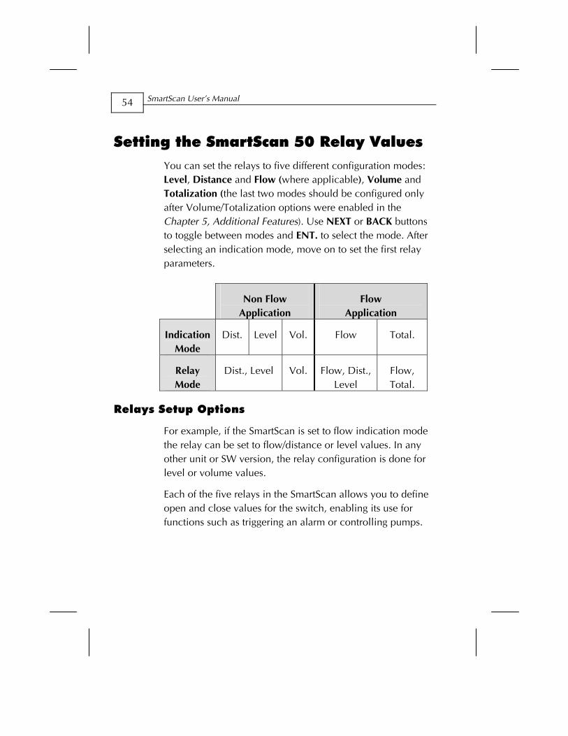
Setting the SmartScan 50 Relay Values You can set the relays to five different configuration modes: Level, Distance and Flow (where applicable), Volume and Totalization (the last two modes should be configured only after Volume/Totalization options were enabled in the Chapter 5, Additional Features). Use NEXT or BACK buttons to toggle between modes and ENT. to select the mode. After selecting an indication mode, move on to set the first relay parameters.
Non Flow Application
Flow Application
Indication Mode
Dist. Level Vol. Flow Total.
Relay Mode
Dist., Level Vol. Flow, Dist., Level
Flow, Total.
Relays Setup Options
For example, if the SmartScan is set to flow indication mode the relay can be set to flow/distance or level values. In any other unit or SW version, the relay configuration is done for level or volume values.
Each of the five relays in the SmartScan allows you to define open and close values for the switch, enabling its use for functions such as triggering an alarm or controlling pumps.
Basic Setup CHAPTER 3
55
In addition, relay four (4) can be configured to report error messages and relay five (5) for flow totalization pulse setup (see detailed configuration instructions on pages 60, 61).
The relay values function as follows:
Open value: (Default = 0) The relay opens if the level measured in the tank is higher than the entered open value.
Close value: (Default = 0) The relay closes if the level measured in the tank is lower than the entered close value.
NOTES: The indication mode default state is Level. The chosen mode will be applicable for all five relays. The close value must be lower than the open value for each relay, otherwise an message is displayed.
An message is displayed if a relay value is greater than the tank height value. In case of no measurement (caused by electronic problem or acoustic
interference) relays will switch to Close state. For safety reasons relays parameters will reset when the following parameters will be modified: Tank height, relays indication mode (Level/ Distance/Flow), measurement mode (except when changing from Level to Distance and vise versa) Flume/Weir type, measurement units, strapping table
SmartScan User’s Manual
56
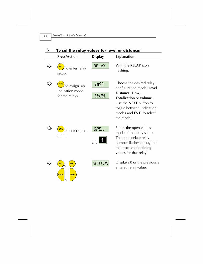
To set the relay values for level or distance:
Press/Action Display Explanation
to enter relay setup.
With the RELAY icon flashing.
to assign an indication mode for the relays.
Choose the desired relay configuration mode: Level, Distance, Flow, Totalization or volume. Use the NEXT button to toggle between indication modes and ENT. to select the mode.
to enter open mode.
and
Enters the open values mode of the relay setup. The appropriate relay number flashes throughout the process of defining values for that relay.
or
or
Displays 0 or the previously entered relay value.
Basic Setup CHAPTER 3
57
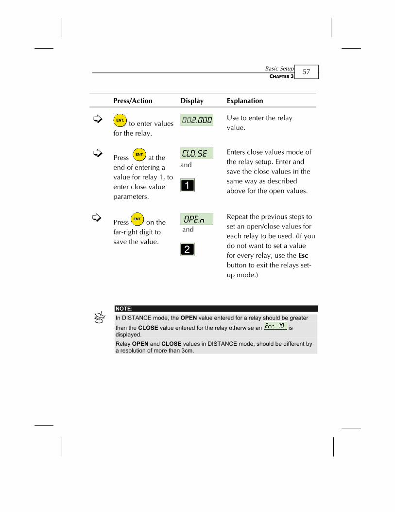
Press/Action Display Explanation
to enter values for the relay.
Use to enter the relay value.
Press at the end of entering a value for relay 1, to enter close value parameters.
and
Enters close values mode of the relay setup. Enter and save the close values in the same way as described above for the open values.
Press on the far-right digit to save the value.
and
Repeat the previous steps to set an open/close values for each relay to be used. (If you do not want to set a value for every relay, use the Esc button to exit the relays set-up mode.)
NOTE: In DISTANCE mode, the OPEN value entered for a relay should be greater
than the CLOSE value entered for the relay otherwise an is displayed. Relay OPEN and CLOSE values in DISTANCE mode, should be different by a resolution of more than 3cm.
SmartScan User’s Manual
58
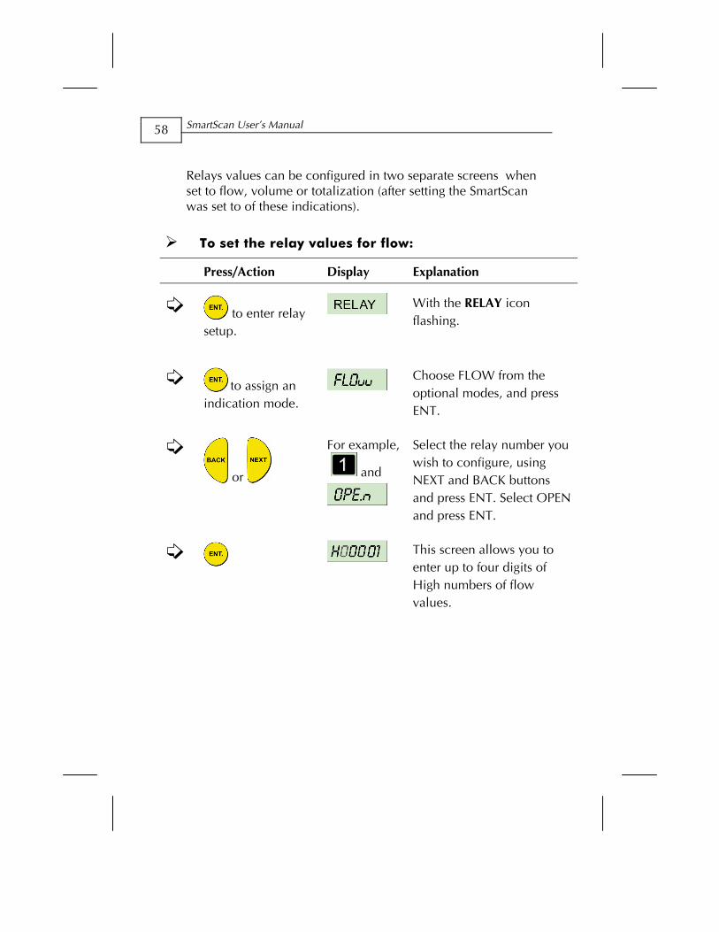
Relays values can be configured in two separate screens when set to flow, volume or totalization (after setting the SmartScan was set to of these indications).
To set the relay values for flow:
Press/Action Display Explanation
to enter relay setup.
With the RELAY icon flashing.
to assign an
indication mode.
Choose FLOW from the optional modes, and press ENT.
or
For example,
and
Select the relay number you wish to configure, using NEXT and BACK buttons and press ENT. Select OPEN and press ENT.
This screen allows you to enter up to four digits of High numbers of flow values.
Basic Setup CHAPTER 3
59
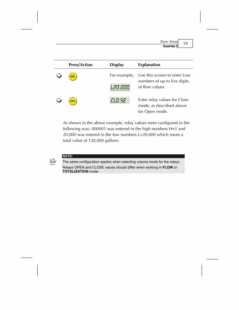
Press/Action Display Explanation
For example,
Use this screen to enter Low numbers of up to five digits of flow values.
Enter relay values for Close mode, as described above for Open mode.
As shown in the above example, relay values were configured in the following way: 000001 was entered in the high numbers H=1 and 20,000 was entered in the low numbers L=20,000 which mean a total value of 120,000 gallons.
NOTE: The same configuration applies when selecting volume mode for the relays. Relays OPEN and CLOSE values should differ when working in FLOW or TOTALIZATION mode.

SmartScan User’s Manual
60
Setting relay 4 to report errors
This mode enables you to use the relay as a trigger to set on an alarm or siren in case the unit produces inaccurate measurement results due to an electrical failure or acoustic problem. You can configure relay 4 to report errors or to remain in normal set-up mode. Once the error mode is enabled and one of the situations described below will appear, the relay will be closed and an error message will show on the unit display. These error messages will describe the following situations:
- In case of lost echo or when measurement result is higher than tank height.
- Near dead zone.
The relay will remain in Open mode as long as the unit displays proper measurement values.
To set relay 4 for error report:
Press/Action Display Explanation
or
Move to relay 4 using NEXT or BACK buttons and ENT. to enter the relay mode.
Choose Err En to enable error alert or Err dS to disable.
Basic Setup CHAPTER 3
61
Setting relay 5 for flow totalization pulse indication
You can choose to set relay number five (5) for flow totalization pulse indication or to remain in normal set-up mode. This option enables you to reserve the accumulated value gathered by the unit, by using an external counter. In this way the total value will be reserved even if the unit will be replaced. Once set for this option, the relay will generate a pulse per Xm^3 or Gallons of flow depend on the value that you have selected from the following list of optional values (you can define the X value): 1, 10, 100, 1000, 10000, 100000. An electrical pulse will be generated whenever the relay total flow value will be larger than the value selected from the list. You can also choose a pulse width between 20 to 2000 milliseconds with a resolution of 10 milliseconds to match your equipment requirements. For example, the relay will generate a pulse with a duration of 1000ms and each time the value of flow will reach 10,000 M^3 (provided that this value was selected from the optional list of values).
NOTE: Prior to setting relay 5 for pulse indication, you should configure the SmartScan for Totalization (see Chapter 5, Additional Features). To configure relay 4 and 5 to work in a normal setup, select Open or Close mode and enter the required parameters. When configure relay 5 as tOt En, the active options are tOt En and tOt dS. To go back to normal work press tOt dS. The result of the totalization amount is updated every 30 seconds.

SmartScan User’s Manual
62
To set relay 5 for pulse indication:
Press/Action Display Explanation
or
or
Move to relay 5 using NEXT or BACK buttons and ENT. to enter the desired operation mode.
to select enable or disable mode.
Choose tot En to enable pulse indication option or tot-ds to disable this option.
to select a pulse value from the list.
For example,
10,000m³.
Select a pulse value from the list of optional values using NEXT button and then ENT. to save your selection. Optional values are between 1 to 100,000.
to enter a pulse width value (as specified in your equipment).
For example, 1000ms.
Enter a pulse width value between 20 milliseconds and 2000 milliseconds (the resolution of 10 milliseconds).
Following the above configuration example, a pulse with duration of 1000ms will occur each time the total value of flow will reach
10,000m³.
Basic Setup CHAPTER 3
63
Setting the SmartScan 25 Relay Values You can set up to five relay switches for SmartScan 25. Each relay enables you to define open and close values for the switch, for functions such as triggering an alarm.
The relay values function as follows:
Open value: (Default = 0) The relay opens if the level measured in the tank is higher than the entered open value.
Close value: (Default = 0) The relay closes if the level measured in the tank is lower than the entered close value.
NOTES: The close value must be lower than the open value for each relay, otherwise an message is displayed.
An message is displayed if a relay value is greater than the tank height value. In case of no measurement (caused by electronic problem or acoustic
interference) relays will switch to Close state. For safety reasons relays parameters will reset when the following parameters will be modified: Tank height, relays indication mode (Level/ Distance/Flow), measurement mode (except when changing from Level to Distance and vise versa) Flume/Weir type, measurement units, strapping table
SmartScan User’s Manual
64
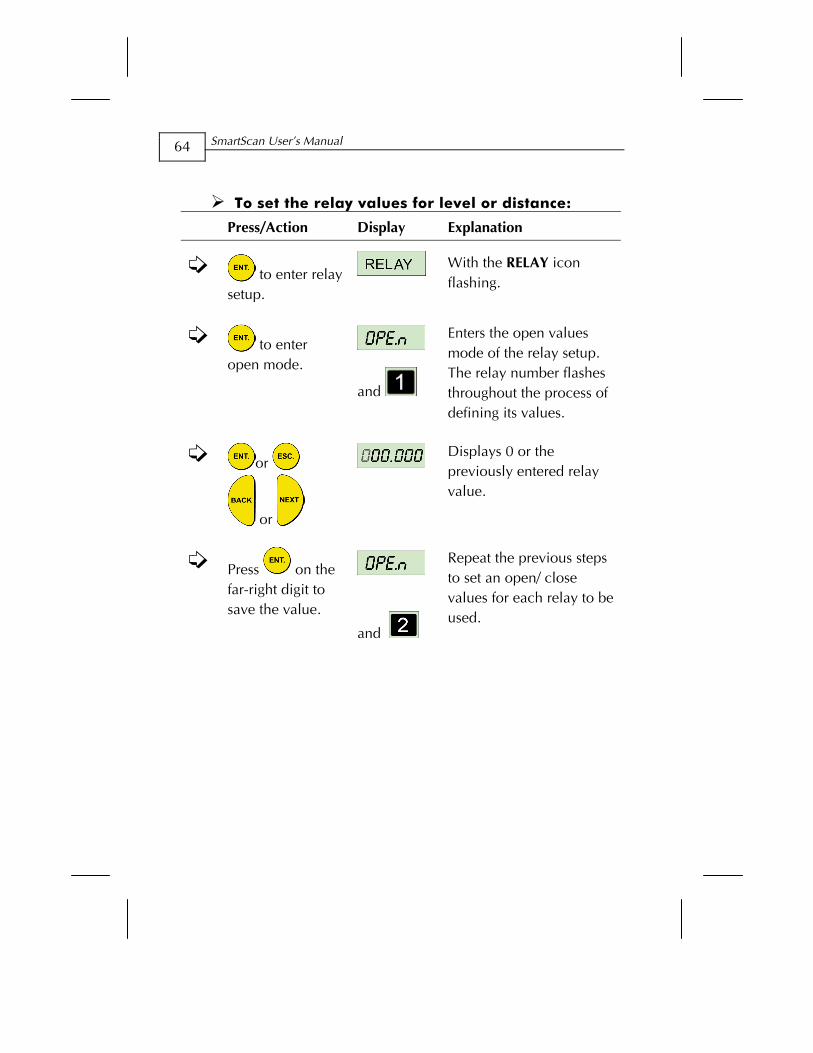
To set the relay values for level or distance:
Press/Action Display Explanation
to enter relay setup.
With the RELAY icon flashing.
to enter open mode.
and
Enters the open values mode of the relay setup. The relay number flashes throughout the process of defining its values.
or
or
Displays 0 or the previously entered relay value.
Press on the far-right digit to save the value.
and
Repeat the previous steps to set an open/ close values for each relay to be used.
Basic Setup CHAPTER 3
65
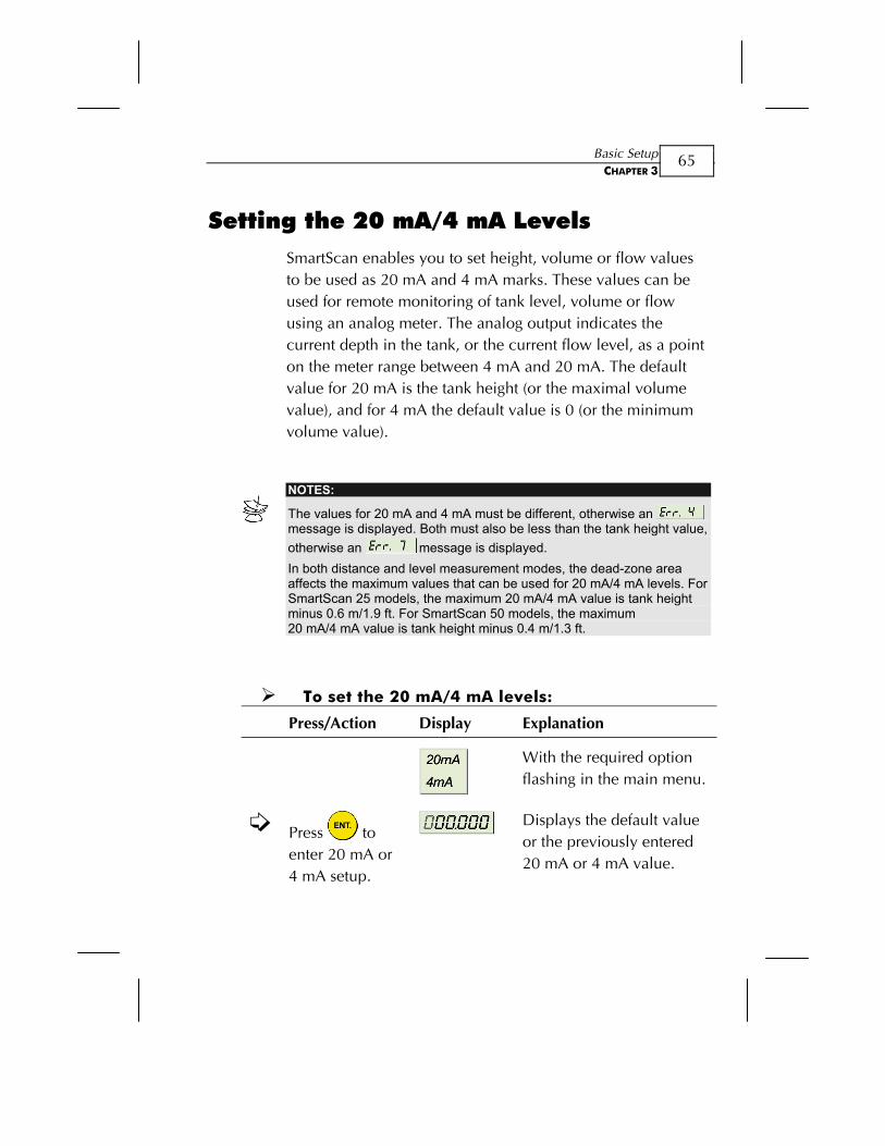
Setting the 20 mA/4 mA Levels SmartScan enables you to set height, volume or flow values to be used as 20 mA and 4 mA marks. These values can be used for remote monitoring of tank level, volume or flow using an analog meter. The analog output indicates the current depth in the tank, or the current flow level, as a point on the meter range between 4 mA and 20 mA. The default value for 20 mA is the tank height (or the maximal volume value), and for 4 mA the default value is 0 (or the minimum volume value).
NOTES:
The values for 20 mA and 4 mA must be different, otherwise an message is displayed. Both must also be less than the tank height value, otherwise an message is displayed. In both distance and level measurement modes, the dead-zone area affects the maximum values that can be used for 20 mA/4 mA levels. For SmartScan 25 models, the maximum 20 mA/4 mA value is tank height minus 0.6 m/1.9 ft. For SmartScan 50 models, the maximum 20 mA/4 mA value is tank height minus 0.4 m/1.3 ft.
To set the 20 mA/4 mA levels:
Press/Action Display Explanation
With the required option flashing in the main menu.
Press to enter 20 mA or 4 mA setup.
Displays the default value or the previously entered 20 mA or 4 mA value.
SmartScan User’s Manual
66
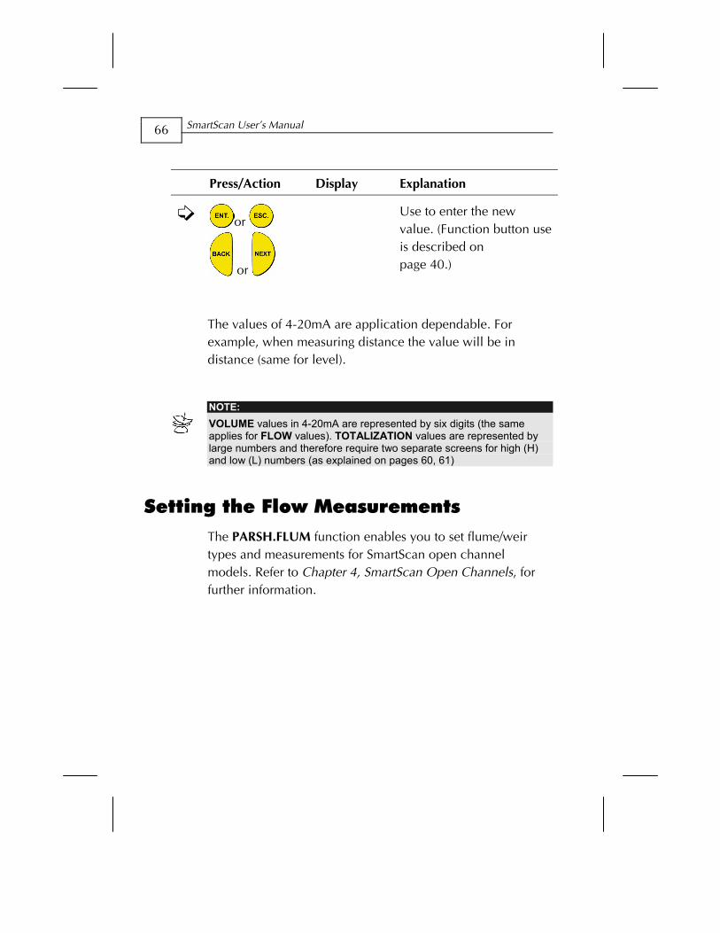
Press/Action Display Explanation
or
or
Use to enter the new value. (Function button use is described on page 40.)
The values of 4-20mA are application dependable. For example, when measuring distance the value will be in distance (same for level).
NOTE: VOLUME values in 4-20mA are represented by six digits (the same applies for FLOW values). TOTALIZATION values are represented by large numbers and therefore require two separate screens for high (H) and low (L) numbers (as explained on pages 60, 61)
Setting the Flow Measurements The PARSH.FLUM function enables you to set flume/weir types and measurements for SmartScan open channel models. Refer to Chapter 4, SmartScan Open Channels, for further information.
Basic Setup CHAPTER 3
67
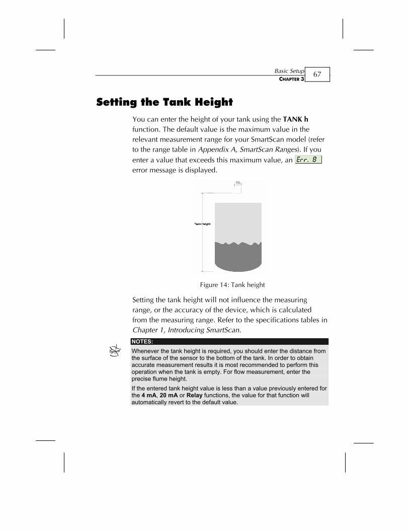
Setting the Tank Height You can enter the height of your tank using the TANK h function. The default value is the maximum value in the relevant measurement range for your SmartScan model (refer to the range table in Appendix A, SmartScan Ranges). If you enter a value that exceeds this maximum value, an
error message is displayed.
Figure 14: Tank height
Setting the tank height will not influence the measuring range, or the accuracy of the device, which is calculated from the measuring range. Refer to the specifications tables in Chapter 1, Introducing SmartScan.
NOTES: Whenever the tank height is required, you should enter the distance from the surface of the sensor to the bottom of the tank. In order to obtain accurate measurement results it is most recommended to perform this operation when the tank is empty. For flow measurement, enter the precise flume height. If the entered tank height value is less than a value previously entered for the 4 mA, 20 mA or Relay functions, the value for that function will automatically revert to the default value.
SmartScan User’s Manual
68
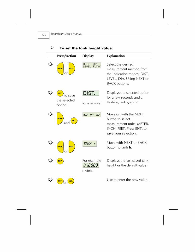
To set the tank height value:
Press/Action Display Explanation
or
Select the desired measurement method from the indication modes: DIST, LEVEL, DIA. Using NEXT or BACK buttons.
to save the selected option.
for example.
Displays the selected option for a few seconds and a flashing tank graphic.
and
Move on with the NEXT button to select measurement units: METER, INCH, FEET. Press ENT. to save your selection.
or
Move with NEXT or BACK button to tank h.
For example
meters.
Displays the last saved tank height or the default value.
or
Use to enter the new value.
Basic Setup CHAPTER 3
69
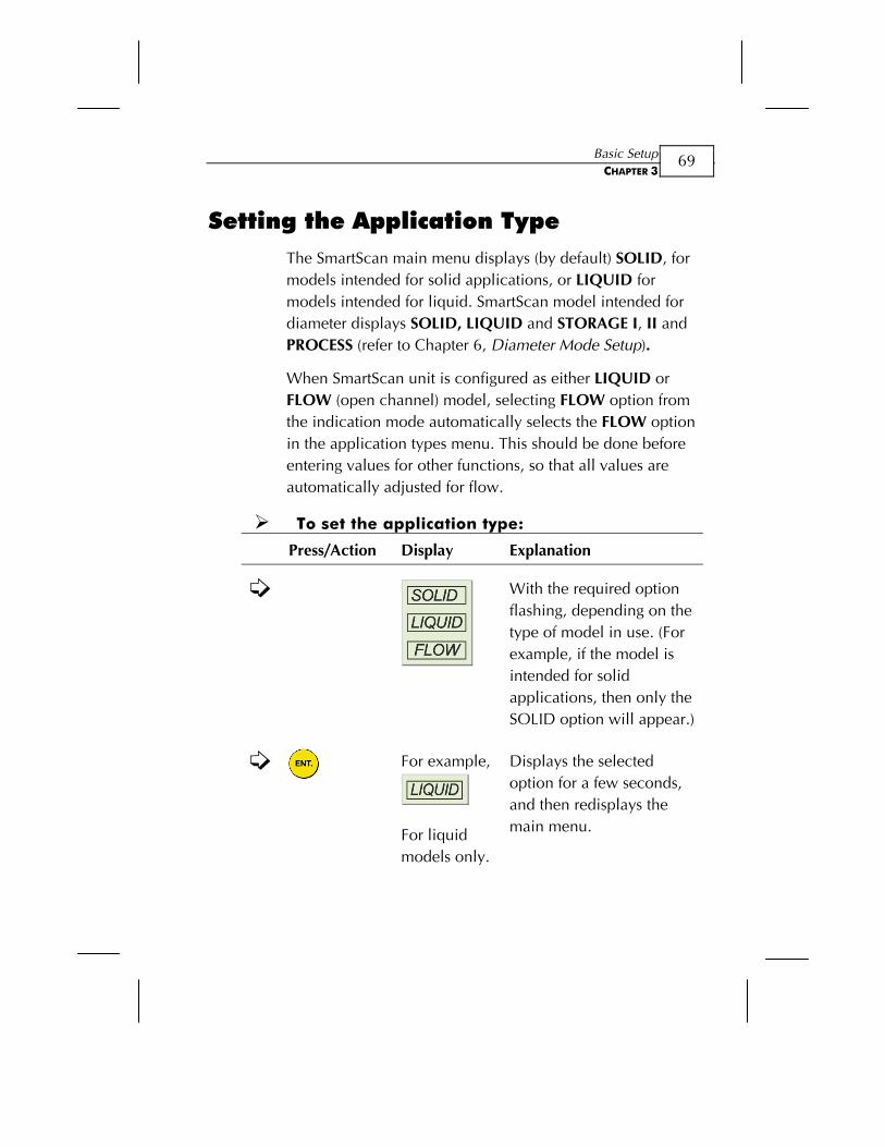
Setting the Application Type The SmartScan main menu displays (by default) SOLID, for models intended for solid applications, or LIQUID for models intended for liquid. SmartScan model intended for diameter displays SOLID, LIQUID and STORAGE I, II and PROCESS (refer to Chapter 6, Diameter Mode Setup).
When SmartScan unit is configured as either LIQUID or FLOW (open channel) model, selecting FLOW option from the indication mode automatically selects the FLOW option in the application types menu. This should be done before entering values for other functions, so that all values are automatically adjusted for flow.
To set the application type:
Press/Action Display Explanation
With the required option flashing, depending on the type of model in use. (For example, if the model is intended for solid applications, then only the SOLID option will appear.)
For example,
For liquid models only.
Displays the selected option for a few seconds, and then redisplays the main menu.
SmartScan User’s Manual
70
Setting the Operation Modes The operation modes function enables you to set SmartScan to compensate for environmental conditions that affect the measurement readings.
For solid and liquid applications, each mode determines the reaction time required for SmartScan to recalibrate when there is a change in the environmental conditions. Depending on the specific requirements for your application, you can select a solid or liquid mode that provides faster readings but with less precision (by performing a smaller number of calculations per cycle), or slower readings with a greater degree of accuracy (by performing a larger number of calculations per cycle).
(For diameter applications, available only for SmartScan 50D model, refer to Chapter 6, Diameter Mode Setup)
The modes settings are defined by making a selection from the STORAGE I, STORAGE II and PROCESS options in the main menu, in some cases in combination with the selection of a particular application type (either SOLID or LIQUID). The mode functions and setup are described in the following sections.
NOTE: The operation modes are not relevant for flow applications. If one of the STORAGE I, STORAGE II or PROCESS options is selected when SmartScan is in FLOW application mode, an warning message is displayed and SmartScan reverts to distance mode. You must then reset the unit to flow mode.
Basic Setup CHAPTER 3
71
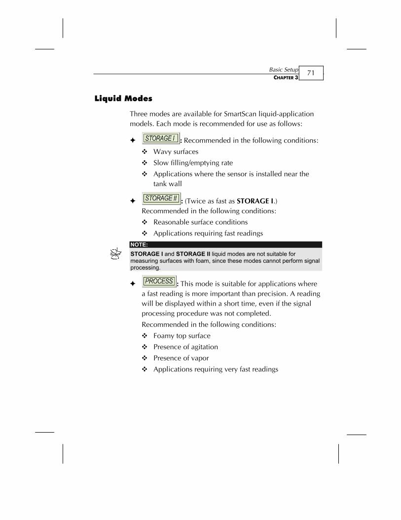
Liquid Modes
Three modes are available for SmartScan liquid-application models. Each mode is recommended for use as follows:
: Recommended in the following conditions:
Wavy surfaces
Slow filling/emptying rate
Applications where the sensor is installed near the tank wall
: (Twice as fast as STORAGE I.) Recommended in the following conditions:
Reasonable surface conditions
Applications requiring fast readings
NOTE: STORAGE I and STORAGE II liquid modes are not suitable for measuring surfaces with foam, since these modes cannot perform signal processing.
: This mode is suitable for applications where a fast reading is more important than precision. A reading will be displayed within a short time, even if the signal processing procedure was not completed.
Recommended in the following conditions:
Foamy top surface
Presence of agitation
Presence of vapor
Applications requiring very fast readings
SmartScan User’s Manual
72
Solid Modes
Three modes are available for SmartScan solid-application models. The main difference between the modes is in the search process required to select the correct echo.
Each mode is recommended for use in the following conditions:
and : Very dusty environments (such as cement)
: Grain applications
Setting the Sensor Offset SmartScan takes measurements from the tip of the sensor. However, when the sensor is located at a point that is above or below the true height of the tank, you can use the MAN function to enter the difference. This may be required, for example, if the sensor is installed at the top of an external pipe, or at the base of an internal pipe in the tank.
When the sensor is located above the tank height, the difference must be subtracted from the actual measurements, so the offset distance is entered as a negative value and vise versa. The maximum permitted offset value is 2.0 m and the minimum permitted value is -2.0 m. Values can be entered in meter units only.
Basic Setup CHAPTER 3
73
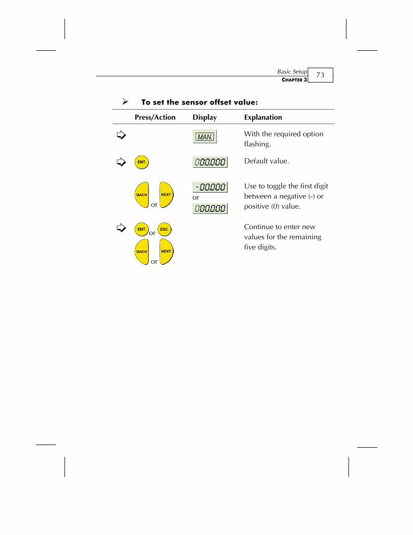
To set the sensor offset value:
Press/Action Display Explanation
With the required option flashing.
Default value.
or
or
Use to toggle the first digit between a negative (-) or positive (0) value.
or
or
Continue to enter new values for the remaining five digits.
SmartScan User’s Manual
74
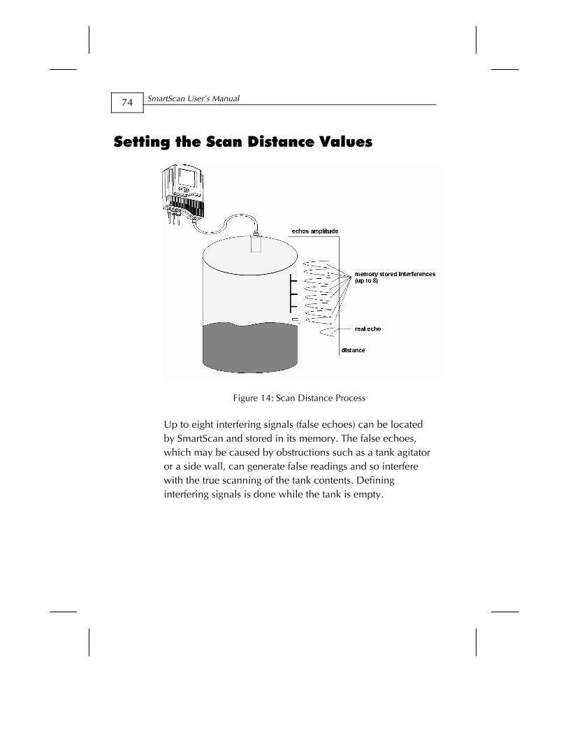
Setting the Scan Distance Values
Figure 14: Scan Distance Process
Up to eight interfering signals (false echoes) can be located by SmartScan and stored in its memory. The false echoes, which may be caused by obstructions such as a tank agitator or a side wall, can generate false readings and so interfere with the true scanning of the tank contents. Defining interfering signals is done while the tank is empty.
Basic Setup CHAPTER 3
75
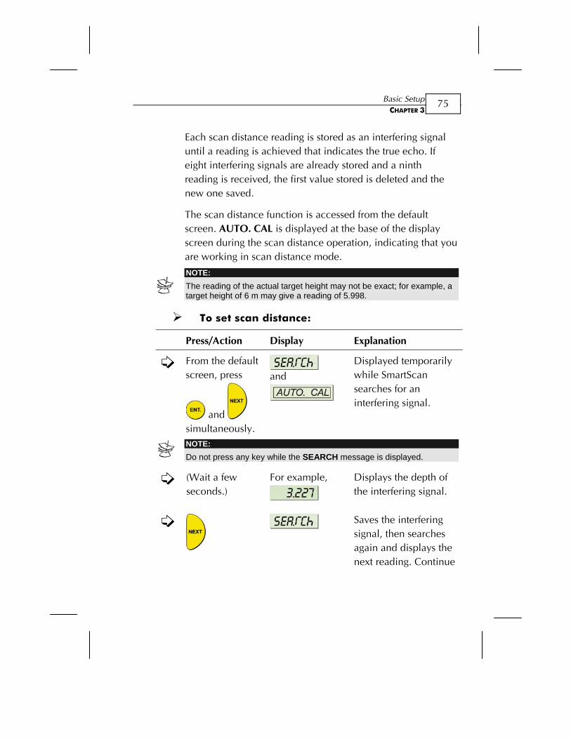
Each scan distance reading is stored as an interfering signal until a reading is achieved that indicates the true echo. If eight interfering signals are already stored and a ninth reading is received, the first value stored is deleted and the new one saved.
The scan distance function is accessed from the default screen. AUTO. CAL is displayed at the base of the display screen during the scan distance operation, indicating that you are working in scan distance mode.
NOTE: The reading of the actual target height may not be exact; for example, a target height of 6 m may give a reading of 5.998.
To set scan distance:
Press/Action Display Explanation
From the default screen, press
and
simultaneously.
and
Displayed temporarily while SmartScan searches for an interfering signal.
NOTE: Do not press any key while the SEARCH message is displayed.
(Wait a few seconds.)
For example,
Displays the depth of the interfering signal.
Saves the interfering signal, then searches again and displays the next reading. Continue
SmartScan User’s Manual
76
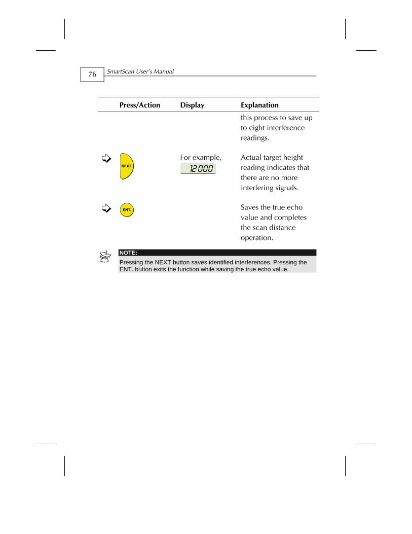
Press/Action Display Explanation
this process to save up to eight interference readings.
For example,
Actual target height reading indicates that there are no more interfering signals.
Saves the true echo
value and completes the scan distance operation.
NOTE: Pressing the NEXT button saves identified interferences. Pressing the ENT. button exits the function while saving the true echo value.
Basic Setup CHAPTER 3
77
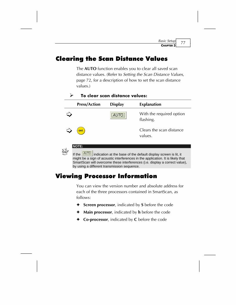
Clearing the Scan Distance Values The AUTO function enables you to clear all saved scan distance values. (Refer to Setting the Scan Distance Values, page 72, for a description of how to set the scan distance values.)
To clear scan distance values:
Press/Action Display Explanation
With the required option flashing.
Clears the scan distance
values.
Viewing Processor Information
NOTE:
If the indication at the base of the default display screen is lit, it might be a sign of acoustic interferences in the application. It is likely that SmartScan will overcome these interferences (i.e. display a correct value), by using a different transmission sequence.
You can view the version number and absolute address for each of the three processors contained in SmartScan, as follows:
Screen processor, indicated by S before the code
Main processor, indicated by h before the code
Co-processor, indicated by C before the code
SmartScan User’s Manual
78
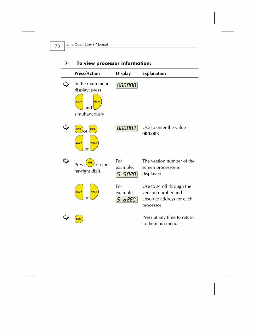
To view processor information:
Press/Action Display Explanation
In the main menu display, press
and
simultaneously.
or
or
Use to enter the value 000.003.
Press on the far-right digit.
For example,
The version number of the screen processor is displayed.
or
For example,
Use to scroll through the version number and absolute address for each processor.
Press at any time to return
to the main menu.
SmartScan Open Channels CHAPTER 4
79
Chapter 4
SmartScan Open Channels
This chapter describes how to set flow measurement parameters for open channels using SmartScan 50O models, and explains the flume/weir codes methodology used when setting up flow measurements.
NOTE: Refer to Chapter 3, Basic Setup, for an explanation of accessing and using the SmartScan main menu and function buttons.
Selecting the Flow Measurement Settings
The PARSH.FLUM function in the main menu enables you to select one of the preset flumes/weirs settings for flow measurements.
SmartScan User’s Manual
80
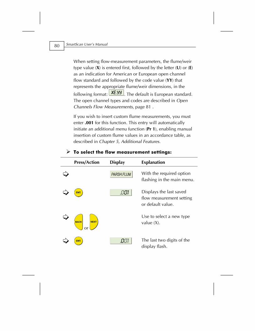
When setting flow-measurement parameters, the flume/weir type value (X) is entered first, followed by the letter (U) or (E) as an indication for American or European open channel flow standard and followed by the code value (YY) that represents the appropriate flume/weir dimensions, in the
following format: . The default is European standard. The open channel types and codes are described in Open Channels Flow Measurements, page 81 .
If you wish to insert custom flume measurements, you must enter .001 for this function. This entry will automatically initiate an additional menu function (Pr 1), enabling manual insertion of custom flume values in an accordance table, as described in Chapter 5, Additional Features.
To select the flow measurement settings:
Press/Action Display Explanation
With the required option flashing in the main menu.
Displays the last saved flow measurement setting or default value.
or
Use to select a new type value (X).
The last two digits of the display flash.
SmartScan Open Channels CHAPTER 4
81
Press/Action Display Explanation
or
Use to select a new flume/weir length code (YY), which corresponds to the type (X) previously selected. (The two digits are modified as one unit.)
The selected values are
saved.
Open Channels Flow Measurements The flume/weir type code methodology used when setting up open channels is based on three digits: X E/U YY
Where:
X refers to the particular flume/weir type
E/U refers to European or American standard
YY refers to the specific flume/weir dimensions
SmartScan User’s Manual
82
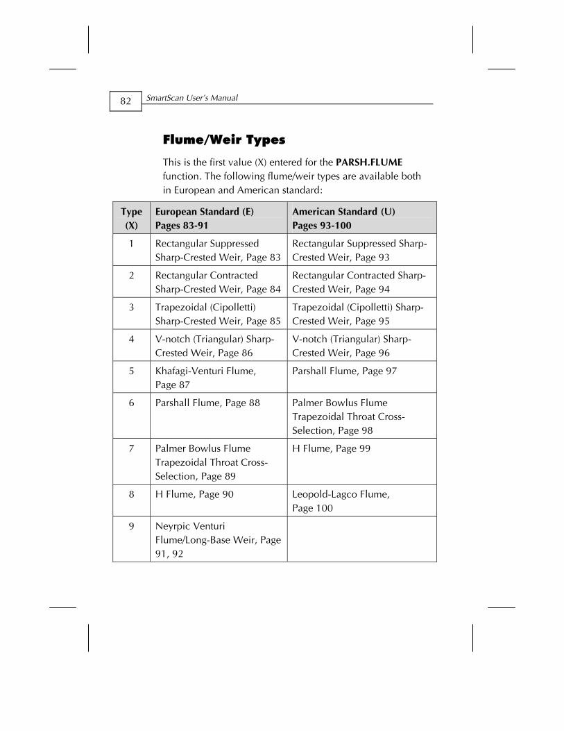
Flume/Weir Types
This is the first value (X) entered for the PARSH.FLUME function. The following flume/weir types are available both in European and American standard:
Type (X)
European Standard (E) Pages 83-91
American Standard (U) Pages 93-100
1 Rectangular Suppressed Sharp-Crested Weir, Page 83
Rectangular Suppressed Sharp-Crested Weir, Page 93
2 Rectangular Contracted Sharp-Crested Weir, Page 84
Rectangular Contracted Sharp-Crested Weir, Page 94
3 Trapezoidal (Cipolletti) Sharp-Crested Weir, Page 85
Trapezoidal (Cipolletti) Sharp-Crested Weir, Page 95
4 V-notch (Triangular) Sharp-Crested Weir, Page 86
V-notch (Triangular) Sharp-Crested Weir, Page 96
5 Khafagi-Venturi Flume, Page 87
Parshall Flume, Page 97
6 Parshall Flume, Page 88 Palmer Bowlus Flume Trapezoidal Throat Cross-Selection, Page 98
7 Palmer Bowlus Flume Trapezoidal Throat Cross-Selection, Page 89
H Flume, Page 99
8 H Flume, Page 90 Leopold-Lagco Flume, Page 100
9 Neyrpic Venturi Flume/Long-Base Weir, Page 91, 92
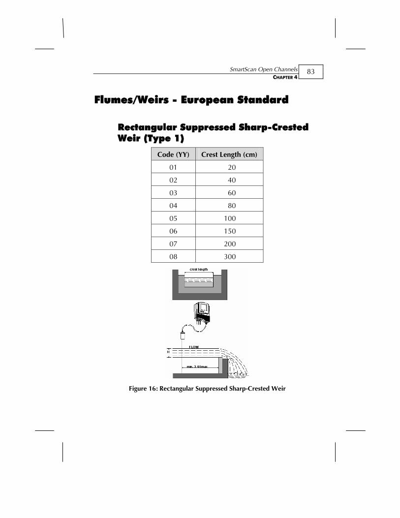
SmartScan Open Channels CHAPTER 4
83
Flumes/Weirs - European Standard
Rectangular Suppressed Sharp-Crested Weir (Type 1)
Code (YY) Crest Length (cm)
01 20
02 40
03 60
04 80
05 100
06 150
07 200
08 300
Figure 16: Rectangular Suppressed Sharp-Crested Weir
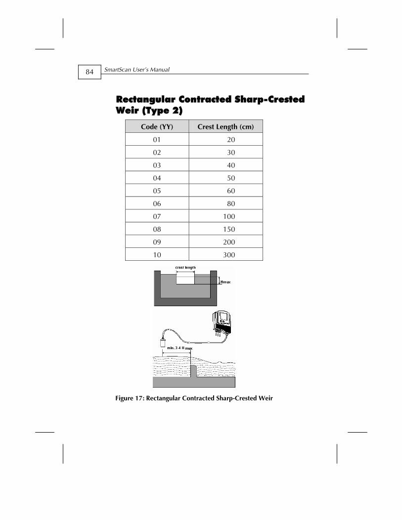
SmartScan User’s Manual
84
Rectangular Contracted Sharp-Crested Weir (Type 2)
Code (YY) Crest Length (cm)
01 20
02 30
03 40
04 50
05 60
06 80
07 100
08 150
09 200
10 300
Figure 17: Rectangular Contracted Sharp-Crested Weir
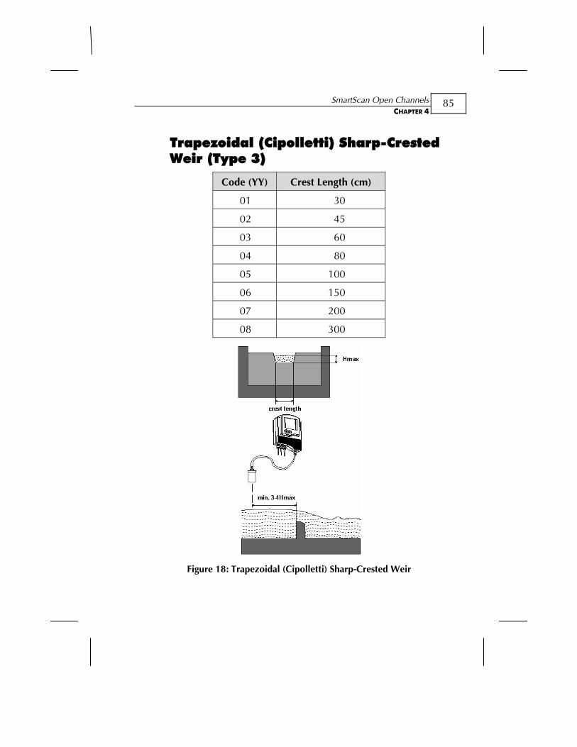
SmartScan Open Channels CHAPTER 4
85
Trapezoidal (Cipolletti) Sharp-Crested Weir (Type 3)
Code (YY) Crest Length (cm)
01 30
02 45
03 60
04 80
05 100
06 150
07 200
08 300
Figure 18: Trapezoidal (Cipolletti) Sharp-Crested Weir
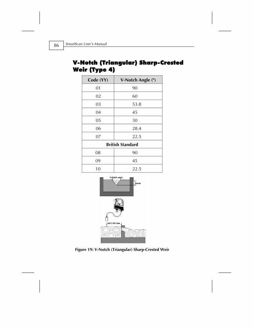
SmartScan User’s Manual
86
V-Notch (Triangular) Sharp-Crested Weir (Type 4)
Code (YY) V-Notch Angle (o)
01 90
02 60
03 53.8
04 45
05 30
06 28.4
07 22.5
British Standard
08 90
09 45
10 22.5
Figure 19: V-Notch (Triangular) Sharp-Crested Weir
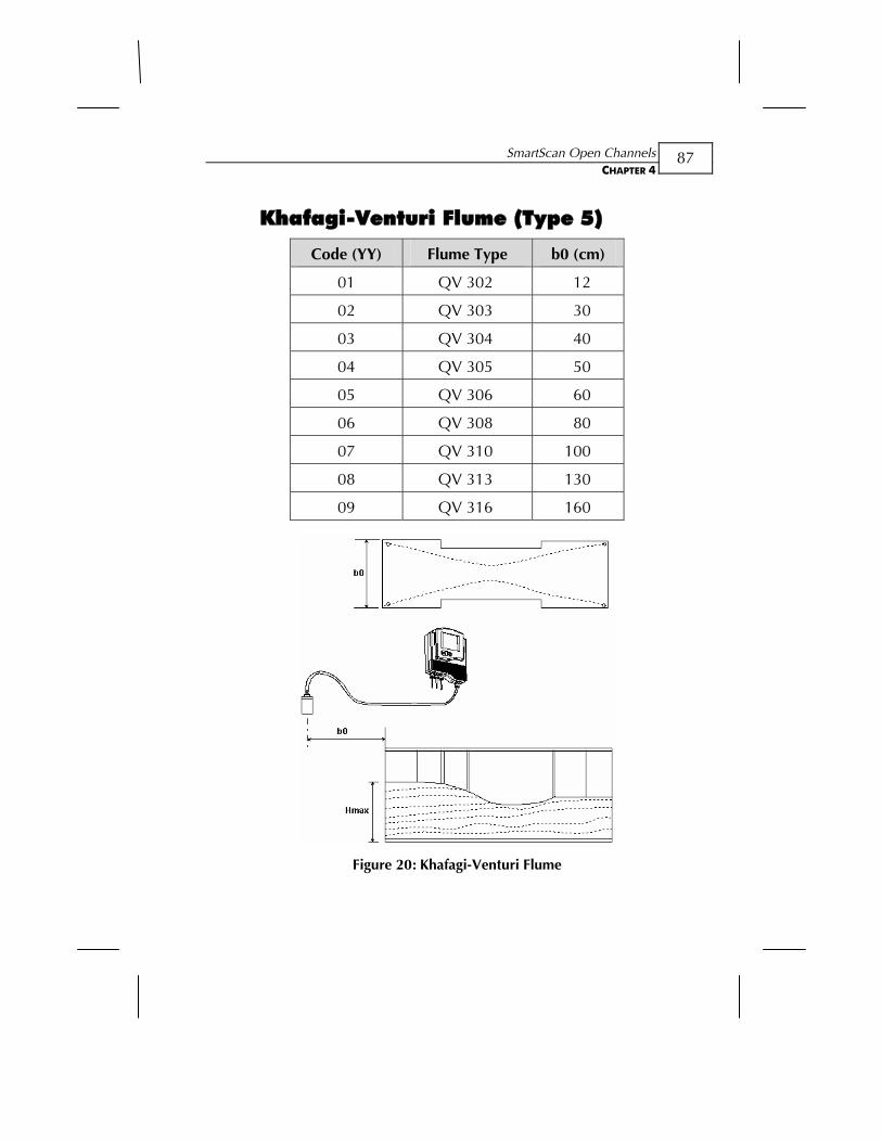
SmartScan Open Channels CHAPTER 4
87
Khafagi-Venturi Flume (Type 5)
Code (YY) Flume Type b0 (cm) 01 QV 302 12
02 QV 303 30
03 QV 304 40
04 QV 305 50
05 QV 306 60
06 QV 308 80
07 QV 310 100
08 QV 313 130
09 QV 316 160
Figure 20: Khafagi-Venturi Flume
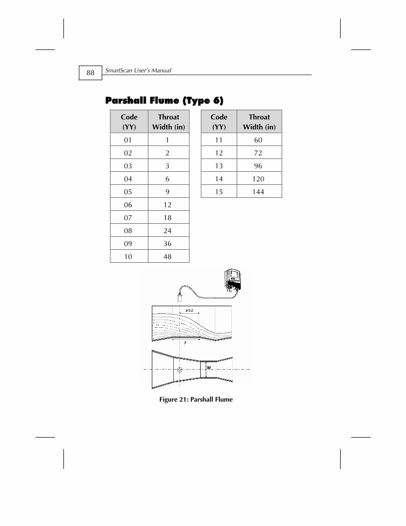
SmartScan User’s Manual
88
Parshall Flume (Type 6)
Code (YY)
Throat Width (in)
Code (YY)
Throat Width (in)
01 1 11 60
02 2 12 72
03 3 13 96
04 6 14 120
05 9 15 144
06 12
07 18
08 24
09 36
10 48
Figure 21: Parshall Flume
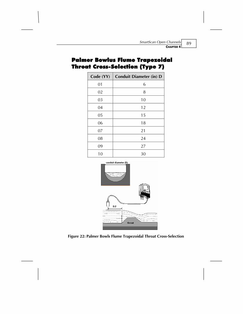
SmartScan Open Channels CHAPTER 4
89
Palmer Bowlus Flume Trapezoidal Throat Cross-Selection (Type 7)
Code (YY) Conduit Diameter (in) D
01 6
02 8
03 10
04 12
05 15
06 18
07 21
08 24
09 27
10 30
Figure 22: Palmer Bowls Flume Trapezoidal Throat Cross-Selection
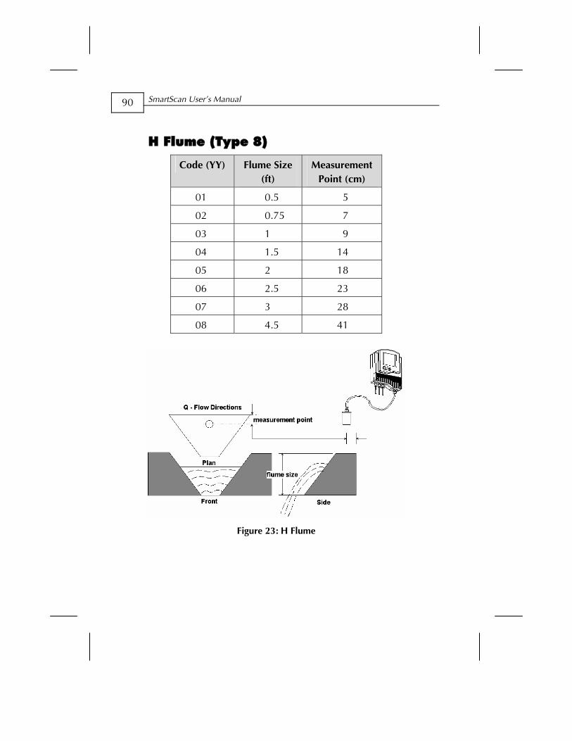
SmartScan User’s Manual
90
H Flume (Type 8)
Code (YY) Flume Size (ft)
Measurement Point (cm)
01 0.5 5
02 0.75 7
03 1 9
04 1.5 14
05 2 18
06 2.5 23
07 3 28
08 4.5 41
Figure 23: H Flume
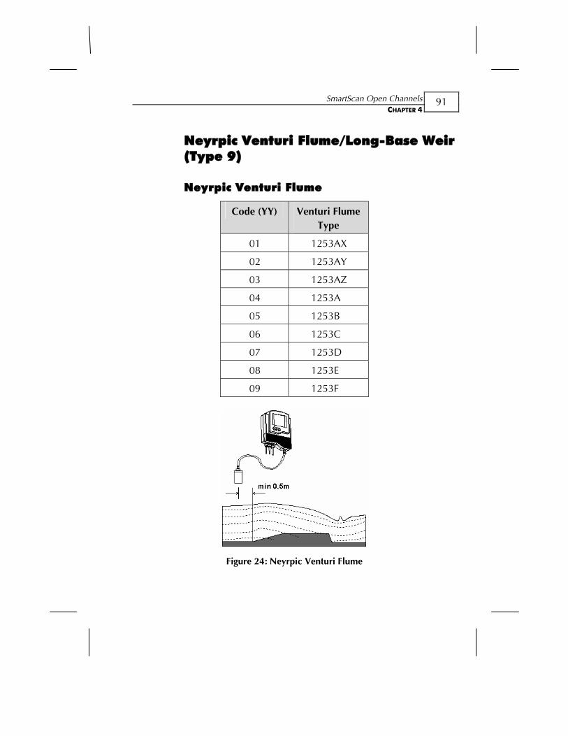
SmartScan Open Channels CHAPTER 4
91
Neyrpic Venturi Flume/Long-Base Weir (Type 9)
Neyrpic Venturi Flume
Code (YY) Venturi Flume Type
01 1253AX
02 1253AY
03 1253AZ
04 1253A
05 1253B
06 1253C
07 1253D
08 1253E
09 1253F
Figure 24: Neyrpic Venturi Flume
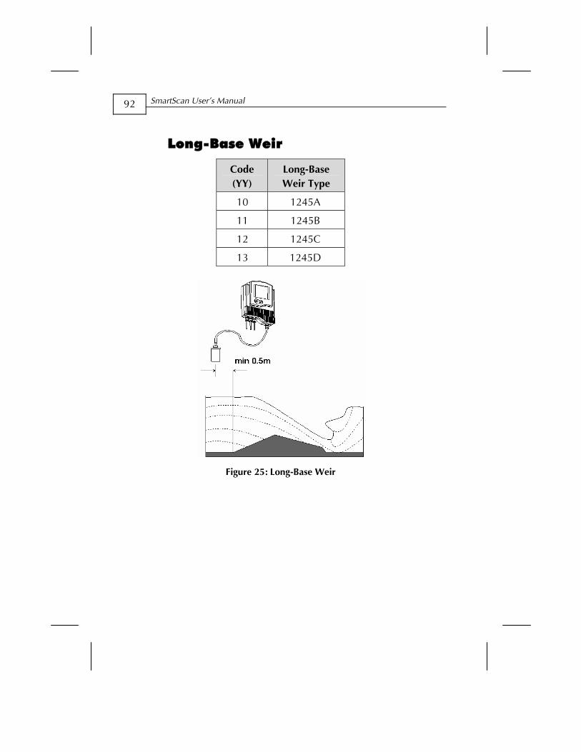
SmartScan User’s Manual
92
Long-Base Weir
Code (YY)
Long-Base Weir Type
10 1245A
11 1245B
12 1245C
13 1245D
Figure 25: Long-Base Weir
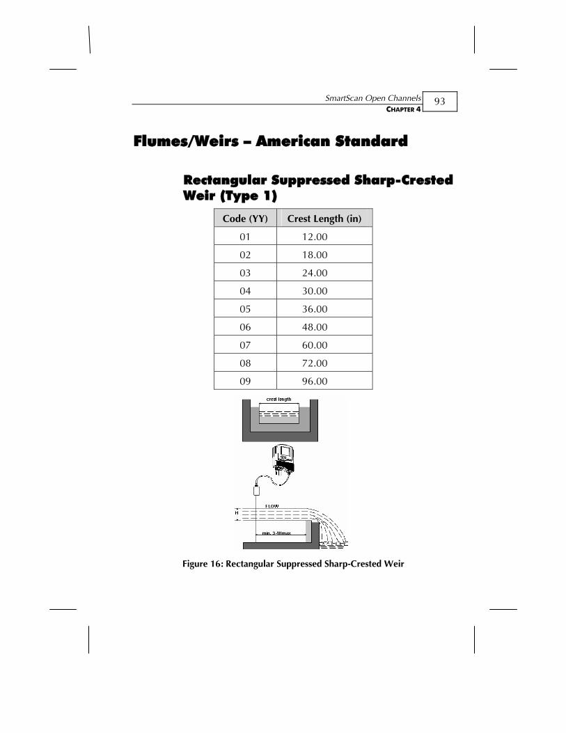
SmartScan Open Channels CHAPTER 4
93
Flumes/Weirs – American Standard
Rectangular Suppressed Sharp-Crested Weir (Type 1)
Code (YY) Crest Length (in)
01 12.00
02 18.00
03 24.00
04 30.00
05 36.00
06 48.00
07 60.00
08 72.00
09 96.00
Figure 16: Rectangular Suppressed Sharp-Crested Weir
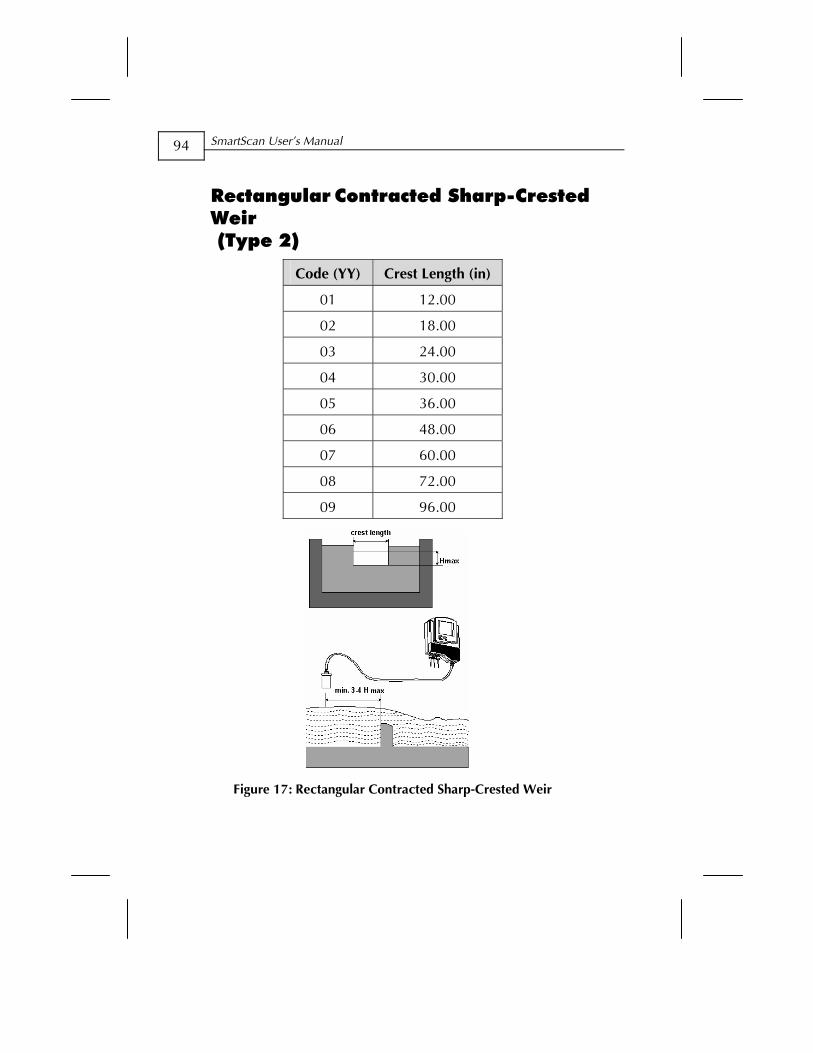
SmartScan User’s Manual
94
Rectangular Contracted Sharp-Crested Weir (Type 2)
Code (YY) Crest Length (in)
01 12.00
02 18.00
03 24.00
04 30.00
05 36.00
06 48.00
07 60.00
08 72.00
09 96.00
Figure 17: Rectangular Contracted Sharp-Crested Weir

SmartScan Open Channels CHAPTER 4
95
Trapezoidal (Cipolletti) Sharp-Crested Weir (Type 3)
Code (YY) Crest Length (in)
01 12.00
02 18.00
03 24.00
04 30.00
05 36.00
06 48.00
07 60.00
08 72.00
09 96.00
Figure 18: Trapezoidal (Cipolletti) Sharp-Crested Weir
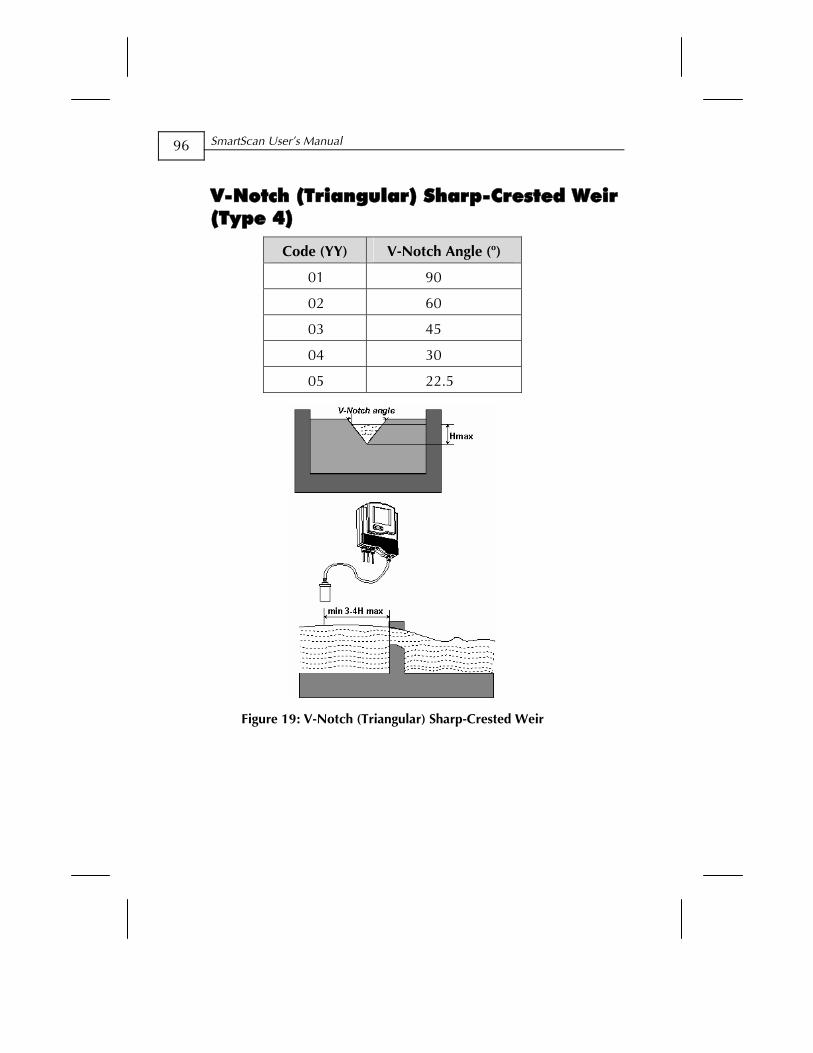
SmartScan User’s Manual
96
V-Notch (Triangular) Sharp-Crested Weir (Type 4)
Code (YY) V-Notch Angle (o)
01 90
02 60
03 45
04 30
05 22.5
Figure 19: V-Notch (Triangular) Sharp-Crested Weir
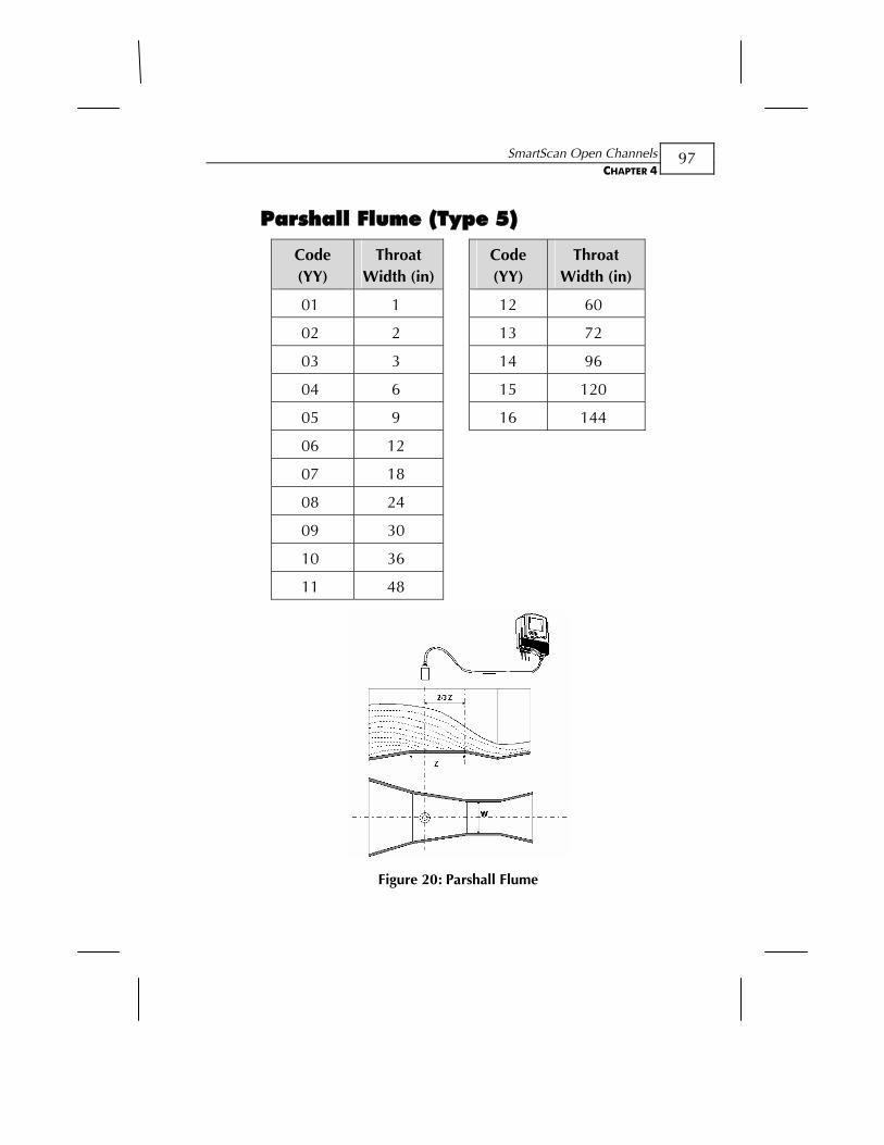
SmartScan Open Channels CHAPTER 4
97
Parshall Flume (Type 5)
Code (YY)
Throat Width (in)
Code (YY)
Throat Width (in)
01 1 12 60
02 2 13 72
03 3 14 96
04 6 15 120
05 9 16 144
06 12
07 18
08 24
09 30
10 36
11 48
Figure 20: Parshall Flume
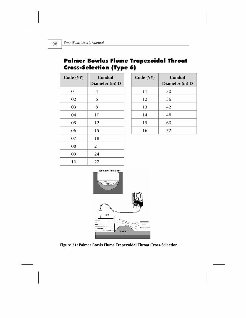
SmartScan User’s Manual
98
Palmer Bowlus Flume Trapezoidal Throat Cross-Selection (Type 6)
Code (YY) Conduit Diameter (in) D
Code (YY) Conduit Diameter (in) D
01 4 11 30
02 6 12 36
03 8 13 42
04 10 14 48
05 12 15 60
06 15 16 72
07 18
08 21
09 24
10 27
Figure 21: Palmer Bowls Flume Trapezoidal Throat Cross-Selection

SmartScan Open Channels CHAPTER 4
99
H Flume (Type 7)
Code (YY)
Flume Size (in)
Measurement Point (in)
01 6 1.96
02 9 2.75
03 12 3.54
04 18 5.51
05 24 7.08
06 30 9.05
07 36 11.02
08 54 16.14
Figure 22: H Flume
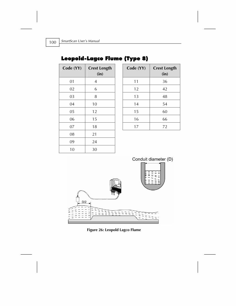
SmartScan User’s Manual
100
Leopold-Lagco Flume (Type 8)
Code (YY) Crest Length (in)
Code (YY) Crest Length (in)
01 4 11 36
02 6 12 42
03 8 13 48
04 10 14 54
05 12 15 60
06 15 16 66
07 18 17 72
08 21
09 24
10 30
Figure 26: Leopold Lagco Flume
Additional Features CHAPTER 5
101
Chapter 5
Additional Features This chapter describes the functions available in SmartScan’s additional menu. The additional menu functions enable you to calibrate SmartScan to perform the following tasks:
Present scanning results in volume format.
Present scanning results as a total accumulative value for flow.
Present scanning results as an accumulative sum for diameter.
Calculate volume for different tank types.
Calculate flow measurements for custom flumes.
Calculate results in alternative measurement units.
Adjust results when there is interference from a conical tank ending.
Allow compensation of different types of gas.
NOTE: The additional menu functions are available via the SmartScan display.
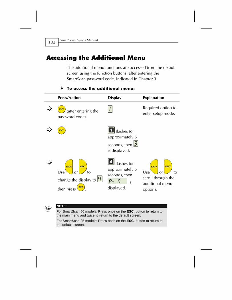
SmartScan User’s Manual
102
Accessing the Additional Menu The additional menu functions are accessed from the default screen using the function buttons, after entering the SmartScan password code, indicated in Chapter 3.
To access the additional menu:
Press/Action Display Explanation
(after entering the password code).
Required option to enter setup mode.
flashes for approximately 5
seconds, then is displayed.
Use or to
change the display to ,
then press .
flashes for approximately 5 seconds, then
is displayed.
Use or to scroll through the additional menu options.
NOTE: For SmartScan 50 models: Press once on the ESC. button to return to the main menu and twice to return to the default screen. For SmartScan 25 models: Press once on the ESC. button to return to the default screen.
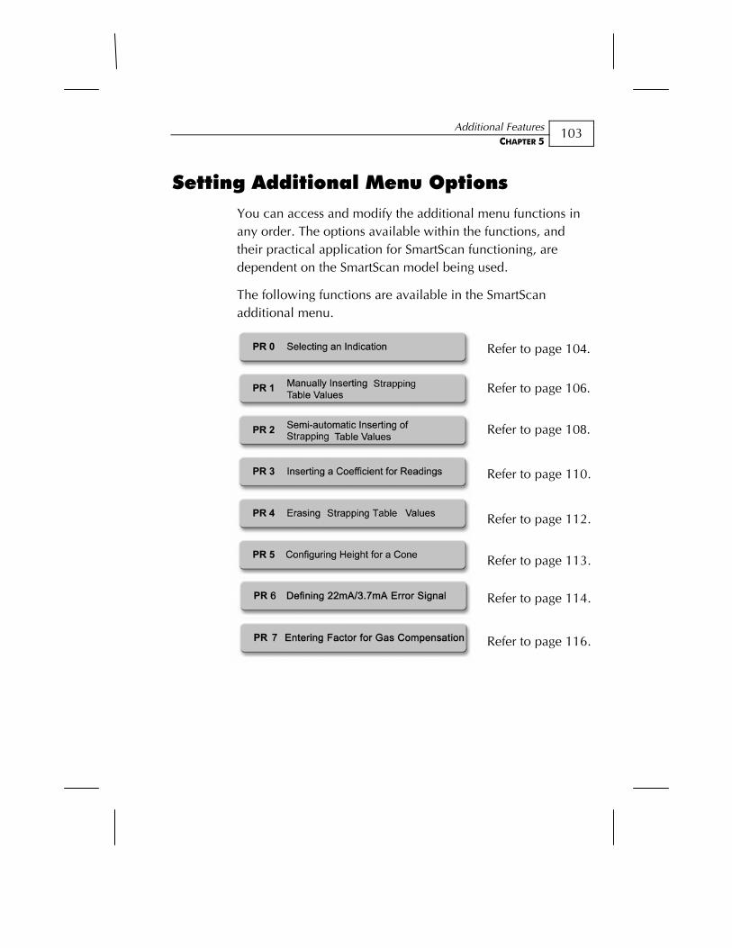
Additional Features CHAPTER 5
103
Setting Additional Menu Options You can access and modify the additional menu functions in any order. The options available within the functions, and their practical application for SmartScan functioning, are dependent on the SmartScan model being used.
The following functions are available in the SmartScan additional menu.
Refer to page 104.
Refer to page 106.
Refer to page 108.
Refer to page 110.
Refer to page 112.
Refer to page 113.
Refer to page 114.
Refer to page 116.
SmartScan User’s Manual
104
Selecting an Indication
Using function Pr 0, you can modify the SmartScan default display to show indications for volume, total flow or diameter sum. Select the required indication mode, as follows:
Ind 1: Volume mode. The default screen indicates the volume reading, by means of a value displayed in the numerical area and the level of the tank graphic.
NOTE: When this mode is selected, you can use Pr 1or Pr 2 to customize volume measurement, as described in Manually Inserting Strapping Table Values, page 106, and Semi-automatic Inserting of Strapping Table Values, page 108.
Ind 2: Totalization for flow mode (currently available for and 50O models SW ver.5.06 onwards). The default screen indicates the value for total accumulative flow, calculated from the point of entering the mode, and updated every 30 seconds. The total amount of flow is shown as a nine-digits value in two separate screens: high and low. The high digits are indicated by an H, followed by the first five digits of the value; the low digits are indicated by an L, followed by the last four digits of the value. You can toggle between the high and low screens using the NEXT and BACK buttons (there is no level indication in the tank graphic for this mode.) In addition, you can toggle between level, distance and flow values using the same buttons. There are three options available in this mode that allows you to, either reset the totalization counter, activate it or deactivate it. Use the NEXT and BACK buttons to toggle between options, and ENT. to select the desired option:
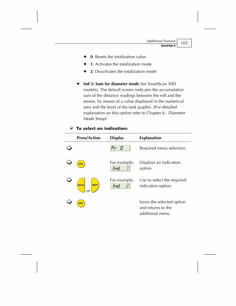
Additional Features CHAPTER 5
105
0: Resets the totalization value
1: Activates the totalization mode
2: Deactivates the totalization mode
Ind 3: Sum for diameter mode (for SmartScan 50D models). The default screen indicates the accumulative sum of the distance readings between the roll and the sensor, by means of a value displayed in the numerical area and the level of the tank graphic. (For detailed explanation on this option refer to Chapter 6, Diameter Mode Setup)
To select an indication:
Press/Action Display Explanation
Required menu selection.
For example,
Displays an indication option.
or
For example,
Use to select the required indication option.
Saves the selected option and returns to the additional menu.
SmartScan User’s Manual
106
Manually Inserting Strapping Table Values
The Pr 1 function enables you to manually create a strapping table of distance points for either volume calculations or custom flume measurements, for the SmartScan 25O and 50O models.
The strapping table is used for manual insertion of distance/volume values when IND 1 was selected as the value for Pr 0, as described in Selecting an Indication, page 104. Manual insertion is applicable when the ratio between the distance and volume of the tank is known or for applications such as custom-shaped tanks. Up to 24 linear points can be entered in the strapping table, starting from the smallest distance and largest volume for point 1 (which is the closest point to the sensor). The distance should increase and the volume decrease with each subsequent entry.
The strapping table automatically enters custom flume mode after .001 is entered as the PARSH.FLUM value in the main menu (refer to Chapter 4, Open Channels Setup). In this mode, the table is used to manually insert up to 24 distance/custom flume measurement values, in the same way as for distance/volume values. Any custom flume measurement can be entered, as long as the maximal value entered is the measurement of the distance between the sensor and the flume.
NOTES:
You can exit Pr 1 at any stage by pressing the ESC button. However, it
is recommended that you first enter at least 8 points for the function. Values are entered in Distance units. When working in custom flume mode, exiting Pr 1 returns you to the main menu.
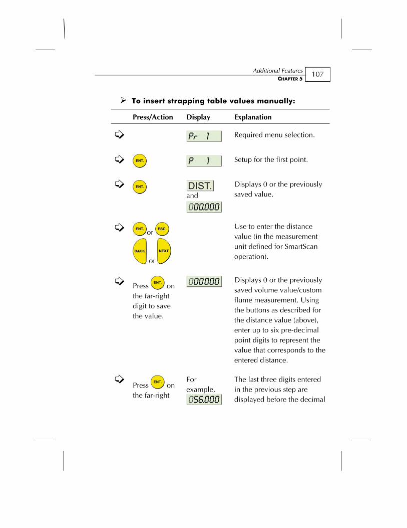
Additional Features CHAPTER 5
107
To insert strapping table values manually:
Press/Action Display Explanation
Required menu selection.
Setup for the first point.
and
Displays 0 or the previously saved value.
or
or
Use to enter the distance value (in the measurement unit defined for SmartScan operation).
Press on the far-right digit to save the value.
Displays 0 or the previously saved volume value/custom flume measurement. Using the buttons as described for the distance value (above), enter up to six pre-decimal point digits to represent the value that corresponds to the entered distance.
Press on the far-right
For example,
The last three digits entered in the previous step are displayed before the decimal
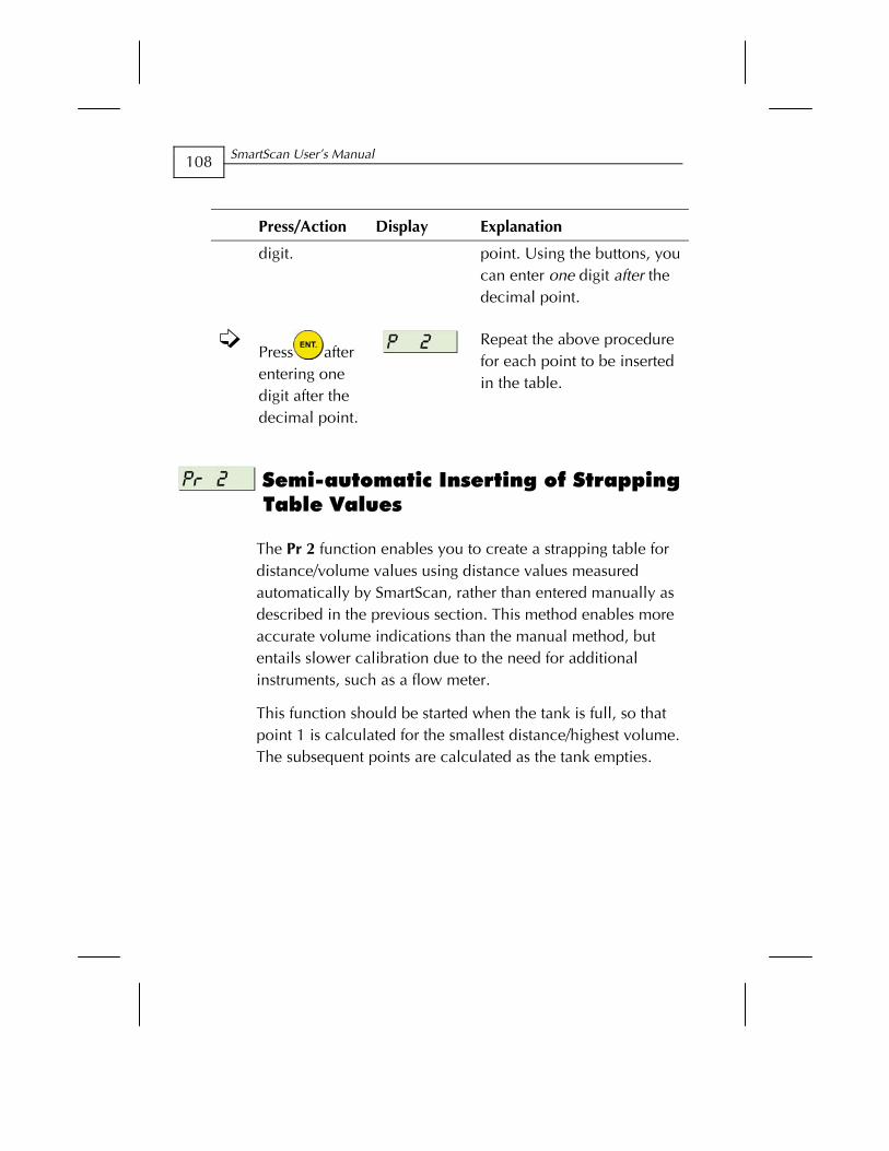
SmartScan User’s Manual
108
Press/Action Display Explanation
digit. point. Using the buttons, you can enter one digit after the decimal point.
Press after entering one digit after the decimal point.
Repeat the above procedure for each point to be inserted in the table.
Semi-automatic Inserting of Strapping Table Values
The Pr 2 function enables you to create a strapping table for distance/volume values using distance values measured automatically by SmartScan, rather than entered manually as described in the previous section. This method enables more accurate volume indications than the manual method, but entails slower calibration due to the need for additional instruments, such as a flow meter.
This function should be started when the tank is full, so that point 1 is calculated for the smallest distance/highest volume. The subsequent points are calculated as the tank empties.
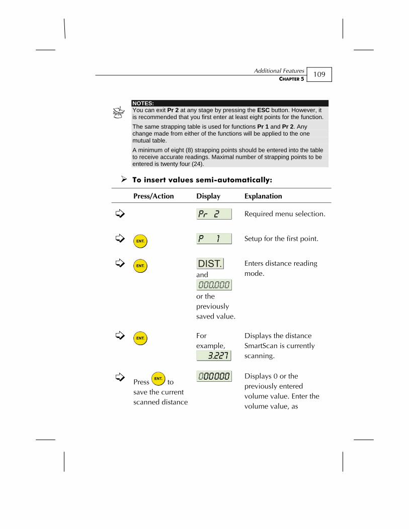
Additional Features CHAPTER 5
109
NOTES: You can exit Pr 2 at any stage by pressing the ESC button. However, it is recommended that you first enter at least eight points for the function. The same strapping table is used for functions Pr 1 and Pr 2. Any change made from either of the functions will be applied to the one mutual table. A minimum of eight (8) strapping points should be entered into the table to receive accurate readings. Maximal number of strapping points to be entered is twenty four (24).
To insert values semi-automatically:
Press/Action Display Explanation
Required menu selection.
Setup for the first point.
and
or the previously saved value.
Enters distance reading mode.
For example,
Displays the distance SmartScan is currently scanning.
Press to save the current scanned distance
Displays 0 or the previously entered volume value. Enter the volume value, as
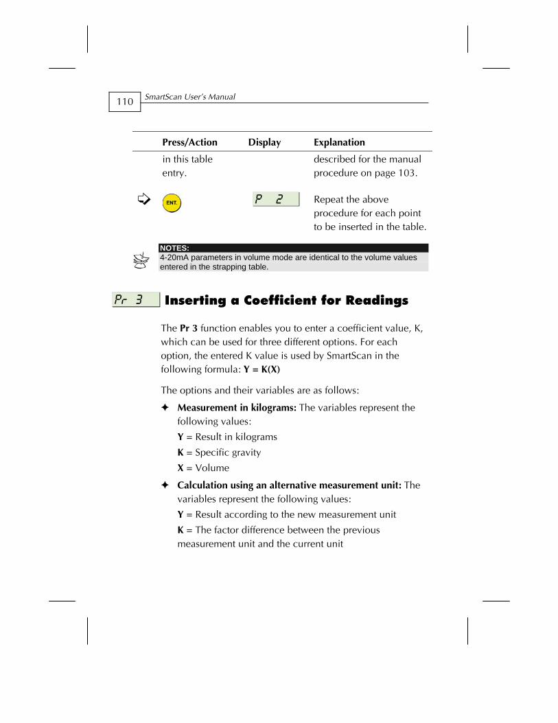
SmartScan User’s Manual
110
Press/Action Display Explanation
in this table entry.
described for the manual procedure on page 103.
Repeat the above procedure for each point to be inserted in the table.
NOTES: 4-20mA parameters in volume mode are identical to the volume values entered in the strapping table.
Inserting a Coefficient for Readings
The Pr 3 function enables you to enter a coefficient value, K, which can be used for three different options. For each option, the entered K value is used by SmartScan in the following formula: Y = K(X)
The options and their variables are as follows:
Measurement in kilograms: The variables represent the following values:
Y = Result in kilograms
K = Specific gravity
X = Volume
Calculation using an alternative measurement unit: The variables represent the following values:
Y = Result according to the new measurement unit
K = The factor difference between the previous measurement unit and the current unit
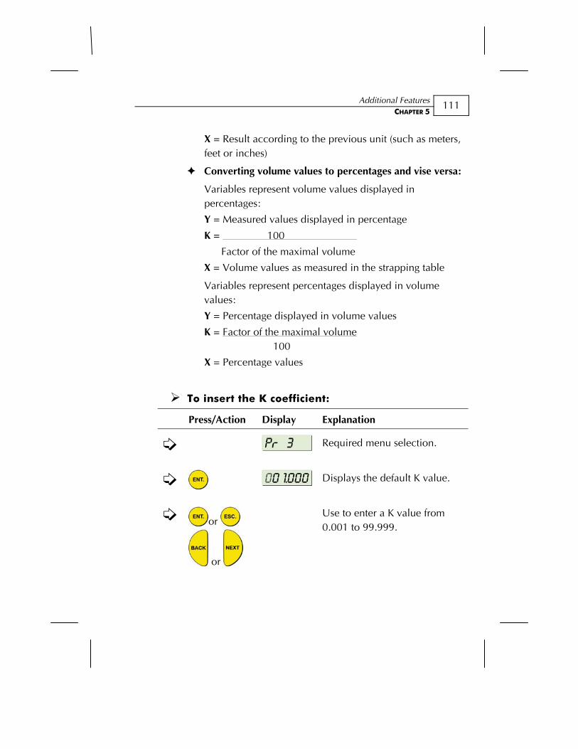
Additional Features CHAPTER 5
111
X = Result according to the previous unit (such as meters, feet or inches)
Converting volume values to percentages and vise versa:
Variables represent volume values displayed in percentages:
Y = Measured values displayed in percentage
K = 100
Factor of the maximal volume
X = Volume values as measured in the strapping table
Variables represent percentages displayed in volume values:
Y = Percentage displayed in volume values
K = Factor of the maximal volume 100
X = Percentage values
To insert the K coefficient:
Press/Action Display Explanation
Required menu selection.
Displays the default K value.
or
or
Use to enter a K value from 0.001 to 99.999.
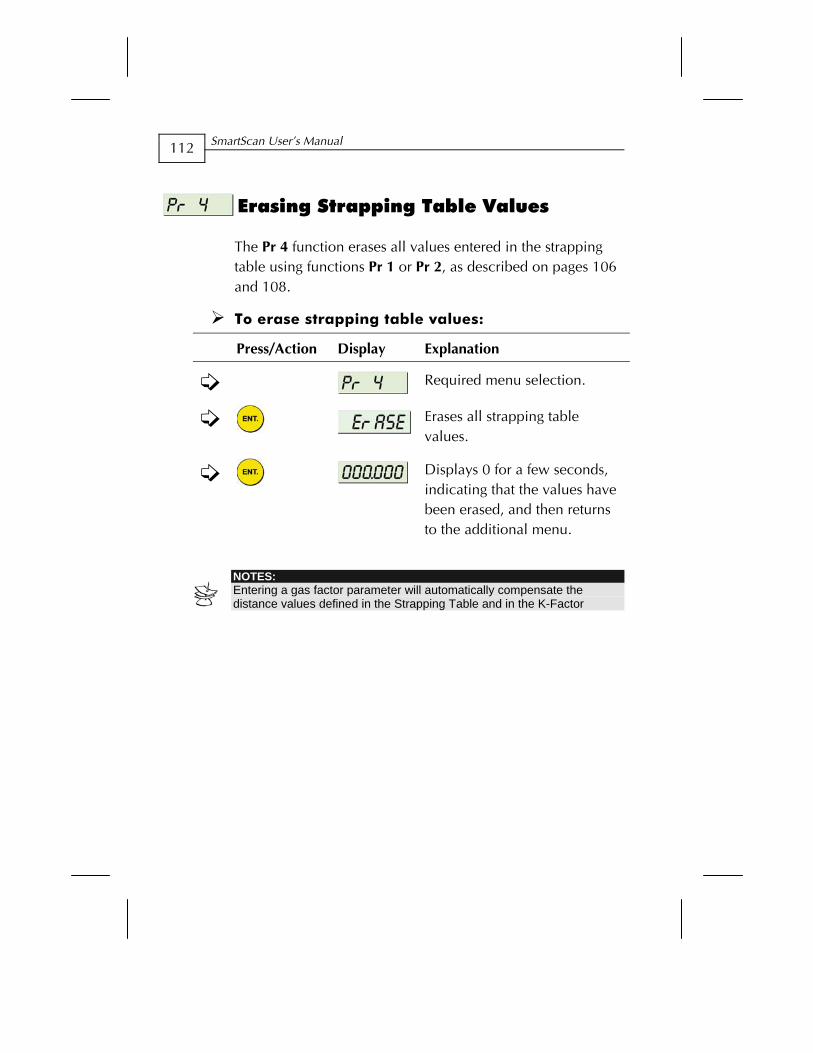
SmartScan User’s Manual
112
Erasing Strapping Table Values
The Pr 4 function erases all values entered in the strapping table using functions Pr 1 or Pr 2, as described on pages 106 and 108.
To erase strapping table values:
Press/Action Display Explanation
Required menu selection.
Erases all strapping table values.
Displays 0 for a few seconds, indicating that the values have been erased, and then returns to the additional menu.
NOTES: Entering a gas factor parameter will automatically compensate the distance values defined in the Strapping Table and in the K-Factor
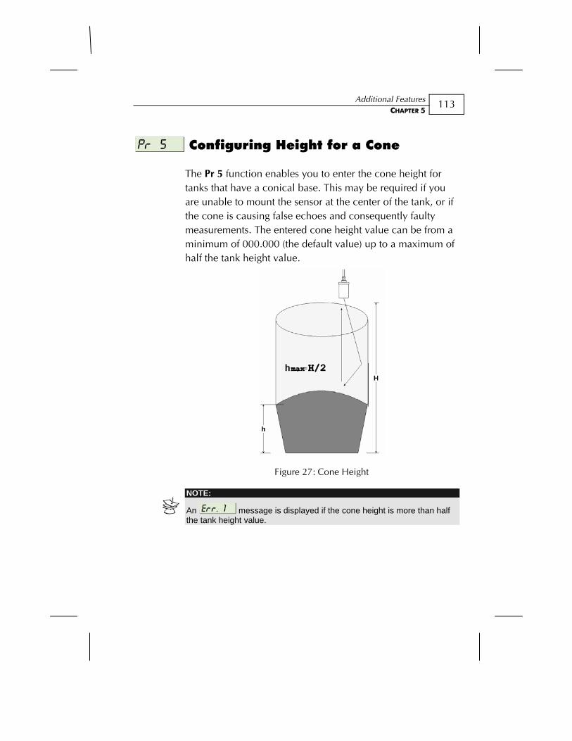
Additional Features CHAPTER 5
113
Configuring Height for a Cone
The Pr 5 function enables you to enter the cone height for tanks that have a conical base. This may be required if you are unable to mount the sensor at the center of the tank, or if the cone is causing false echoes and consequently faulty measurements. The entered cone height value can be from a minimum of 000.000 (the default value) up to a maximum of half the tank height value.
Figure 27: Cone Height
NOTE:
An message is displayed if the cone height is more than half the tank height value.
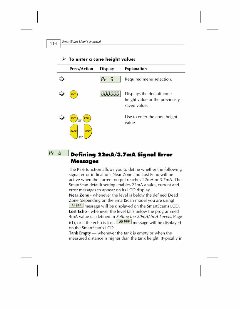
SmartScan User’s Manual
114
To enter a cone height value:
Press/Action Display Explanation
Required menu selection.
Displays the default cone height value or the previously saved value.
or
or
Use to enter the cone height value.
Defining 22mA/3.7mA Signal Error Messages
The Pr 6 function allows you to define whether the following signal error indications Near Zone and Lost Echo will be active when the current output reaches 22mA or 3.7mA. The SmartScan default setting enables 22mA analog current and error messages to appear on its LCD display. Near Zone - whenever the level is below the defined Dead Zone (depending on the SmartScan model you are using)
message will be displayed on the SmartScan’s LCD. Lost Echo - whenever the level falls below the programmed 4mA value (as defined in Setting the 20mA/4mA Levels, Page 61), or if the echo is lost, message will be displayed on the SmartScan’s LCD. Tank Empty — whenever the tank is empty or when the measured distance is higher than the tank height. (typically in

Additional Features CHAPTER 5
115
empty tanks with conic ending), message will be displayed on the SmartScan’s LCD.
You can choose to enable or disable these error messages and 3.7mA/22mA analog signals as follows:
0: Enables 22mA signal error messages
1: Enables 3.7mA signal error messages
2: Disables signal error messages
To select 22mA/3.7mA signal error messages:
Press/Action Display Explanation
Required menu selection.
22mA signal error messages will be activated.
or
or
Use to toggle between the options.
NOTE: The factory default for Error Signal mode is disable.
SmartScan User’s Manual
116
Entering Factor for Gas Compensation in SmartScan 25
Function Pr.07 enables you to compensate for sound velocity changes in different types of gas. You can enter the appropriate factor for each type of gas listed on the ‘Gas Factor Table’ (Appen.B). For example, the sound velocity in air (in room temperature) is 343 m/sec and for Methane (Ch4) 445.82 m/sec, therefore a factor of 445.82/343 = 1.29 should be entered to compensate for this type of gas. This factor will compensate in cases that the gas consists of 100% Methane. In case the gas is not pure, the sound velocity cannot be estimated and therefore a minor deviation could appear. It is recommended to use a reference measurement indicator (using a tape or other measuring device) and compare the measurement results between the SmartScan and the reference measurement indicator. If the result is correct, press ENT. If the accuracy deviation is higher than expected, continue and calibrate the factor to meet the gas maintained in the vessel. For example, if the gas consists of water and gas you can add +/- 0.01 to the factor figure already entered, to meet your application requirements.
The ‘Gas Factor Table’ (Appen.B) supports up to 33 different types of gas. For any other type of gas, not included in this table, please consult with Solid AT Customer Support. ([email protected])
NOTES:
The procedure of adjusting the gas factor parameter should be repeated until the desired measurement value is achieved. If neither ESC nor ENT buttons are pressed within 10 seconds, the original gas factor will be displayed. Entering a gas factor parameter will automatically compensate the distance values defined in the Strapping Table and in the K-Factor. Once the factor entry is approved SmartScan will return to the Additional Menu screen.
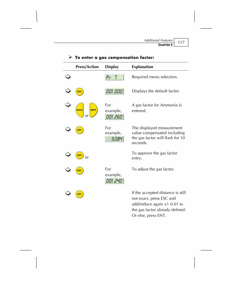
Additional Features CHAPTER 5
117
To enter a gas compensation factor:
Press/Action Display Explanation
Required menu selection.
Displays the default factor.
or
For example,
A gas factor for Ammonia is entered.
For example,
The displayed measurement value compensated including the gas factor will flash for 10 seconds.
or
To approve the gas factor entry.
For example,
To adjust the gas factor.
If the accepted distance is still not exact, press ESC and add/reduce again +/- 0.01 to the gas factor already defined. Or else, press ENT.
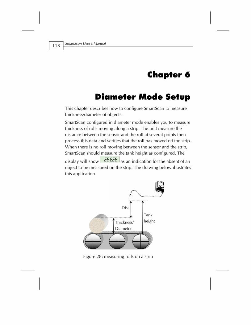
SmartScan User’s Manual
118
Chapter 6
Diameter Mode Setup This chapter describes how to configure SmartScan to measure thickness/diameter of objects.
SmartScan configured in diameter mode enables you to measure thickness of rolls moving along a strip. The unit measure the distance between the sensor and the roll at several points then process this data and verifies that the roll has moved off the strip. When there is no roll moving between the sensor and the strip, SmartScan should measure the tank height as configured. The
display will show as an indication for the absent of an object to be measured on the strip. The drawing below illustrates this application.
Figure 28: measuring rolls on a strip
Dist.
Thickness/
Diameter
Tank
height
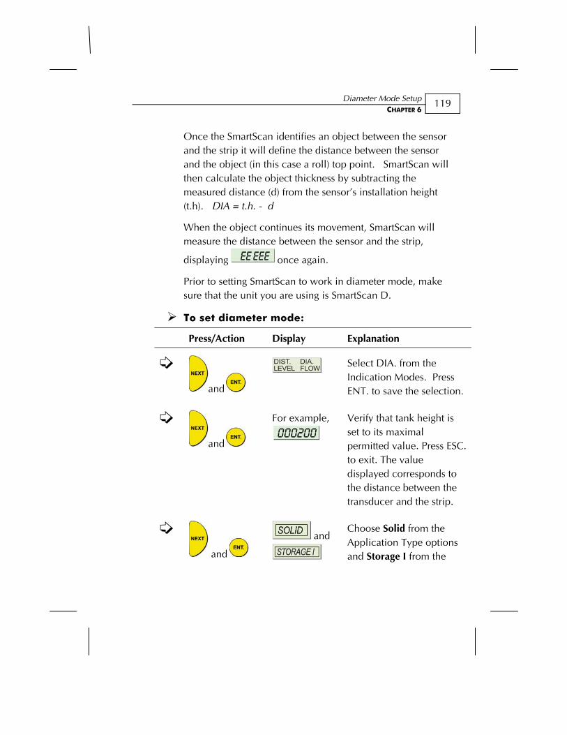
Diameter Mode Setup CHAPTER 6
119
Once the SmartScan identifies an object between the sensor and the strip it will define the distance between the sensor and the object (in this case a roll) top point. SmartScan will then calculate the object thickness by subtracting the measured distance (d) from the sensor’s installation height (t.h). DIA = t.h. - d
When the object continues its movement, SmartScan will measure the distance between the sensor and the strip,
displaying once again.
Prior to setting SmartScan to work in diameter mode, make sure that the unit you are using is SmartScan D.
To set diameter mode:
Press/Action Display Explanation
and
Select DIA. from the Indication Modes. Press ENT. to save the selection.
and
For example,
Verify that tank height is set to its maximal permitted value. Press ESC. to exit. The value displayed corresponds to the distance between the transducer and the strip.
and
and
Choose Solid from the Application Type options and Storage I from the

SmartScan User’s Manual
120
Press/Action Display Explanation
Operation Mode. Press ENT. to save your selection.
to exit and
return to the
default menu.
The unit will display this message as long as there is no roll detected by the transducer.
Operation Modes for Diameter application
Five operation modes are available for SmartScan 50D, diameter-application models, defined by selecting either SOLID or LIQUID in combination with one of the mode options.
Mode Main Menu Selection:
Application Type Main Menu Selection:
Mode Type
0
1
2
3
4
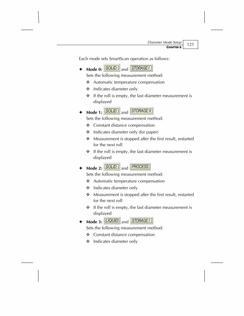
Diameter Mode Setup CHAPTER 6
121
Each mode sets SmartScan operation as follows:
Mode 0: and
Sets the following measurement method:
Automatic temperature compensation
Indicates diameter only
If the roll is empty, the last diameter measurement is displayed
Mode 1: and Sets the following measurement method:
Constant distance compensation
Indicates diameter only (for paper)
Measurement is stopped after the first result, restarted for the next roll
If the roll is empty, the last diameter measurement is displayed
Mode 2: and Sets the following measurement method:
Automatic temperature compensation
Indicates diameter only
Measurement is stopped after the first result, restarted for the next roll
If the roll is empty, the last diameter measurement is displayed
Mode 3: and Sets the following measurement method:
Constant distance compensation
Indicates diameter only
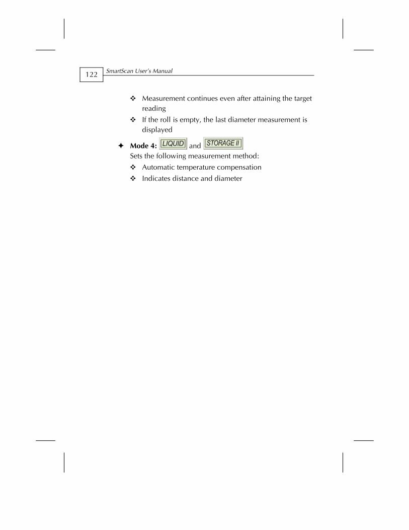
SmartScan User’s Manual
122
Measurement continues even after attaining the target reading
If the roll is empty, the last diameter measurement is displayed
Mode 4: and Sets the following measurement method:
Automatic temperature compensation
Indicates distance and diameter
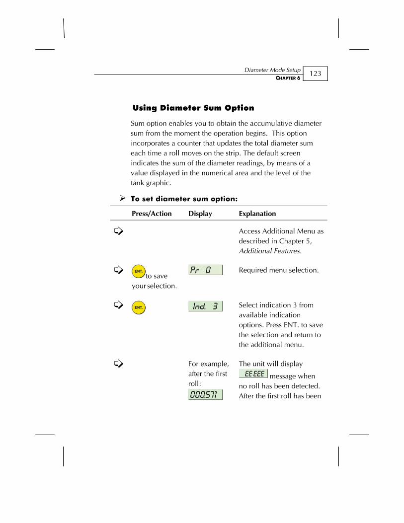
Diameter Mode Setup CHAPTER 6
123
Using Diameter Sum Option
Sum option enables you to obtain the accumulative diameter sum from the moment the operation begins. This option incorporates a counter that updates the total diameter sum each time a roll moves on the strip. The default screen indicates the sum of the diameter readings, by means of a value displayed in the numerical area and the level of the tank graphic.
To set diameter sum option:
Press/Action Display Explanation
Access Additional Menu as described in Chapter 5, Additional Features.
to save your selection.
Required menu selection.
Select indication 3 from available indication options. Press ENT. to save the selection and return to the additional menu.
For example, after the first roll:
The unit will display
message when no roll has been detected. After the first roll has been
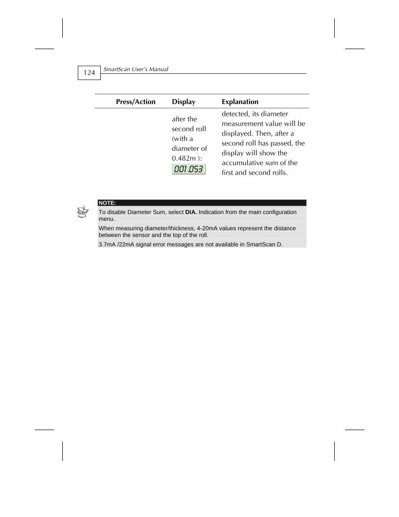
SmartScan User’s Manual
124
Press/Action Display Explanation
after the second roll (with a diameter of 0.482m ):
detected, its diameter measurement value will be displayed. Then, after a second roll has passed, the display will show the accumulative sum of the first and second rolls.
NOTE: To disable Diameter Sum, select DIA. Indication from the main configuration menu. When measuring diameter/thickness, 4-20mA values represent the distance between the sensor and the top of the roll. 3.7mA /22mA signal error messages are not available in SmartScan D.
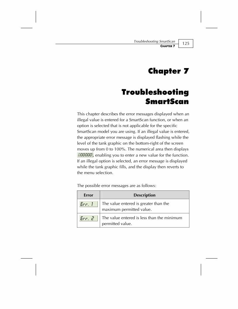
Troubleshooting SmartScan CHAPTER 7
125
Chapter 7
Troubleshooting SmartScan
This chapter describes the error messages displayed when an illegal value is entered for a SmartScan function, or when an option is selected that is not applicable for the specific SmartScan model you are using. If an illegal value is entered, the appropriate error message is displayed flashing while the level of the tank graphic on the bottom-right of the screen moves up from 0 to 100%. The numerical area then displays
, enabling you to enter a new value for the function. If an illegal option is selected, an error message is displayed while the tank graphic fills, and the display then reverts to the menu selection.
The possible error messages are as follows:
Error Description
The value entered is greater than the maximum permitted value.
The value entered is less than the minimum permitted value.
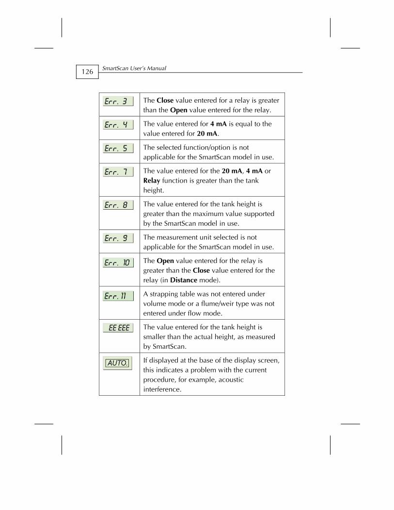
SmartScan User’s Manual
126
The Close value entered for a relay is greater than the Open value entered for the relay.
The value entered for 4 mA is equal to the value entered for 20 mA.
The selected function/option is not applicable for the SmartScan model in use.
The value entered for the 20 mA, 4 mA or Relay function is greater than the tank height.
The value entered for the tank height is greater than the maximum value supported by the SmartScan model in use.
The measurement unit selected is not applicable for the SmartScan model in use.
The Open value entered for the relay is greater than the Close value entered for the relay (in Distance mode).
A strapping table was not entered under volume mode or a flume/weir type was not entered under flow mode.
The value entered for the tank height is smaller than the actual height, as measured by SmartScan.
If displayed at the base of the display screen, this indicates a problem with the current procedure, for example, acoustic interference.

Troubleshooting SmartScan CHAPTER 7
127
22mA/3.7mA Signal Error Messages
The following list of messages will appear on the display and coincides with a 22mA or 3.7mA (depends on your set-up) analog current error output signal (the default is set to 22mA):
Error Description
Tank is empty or echo is lost
The sensor is located near the dead zone
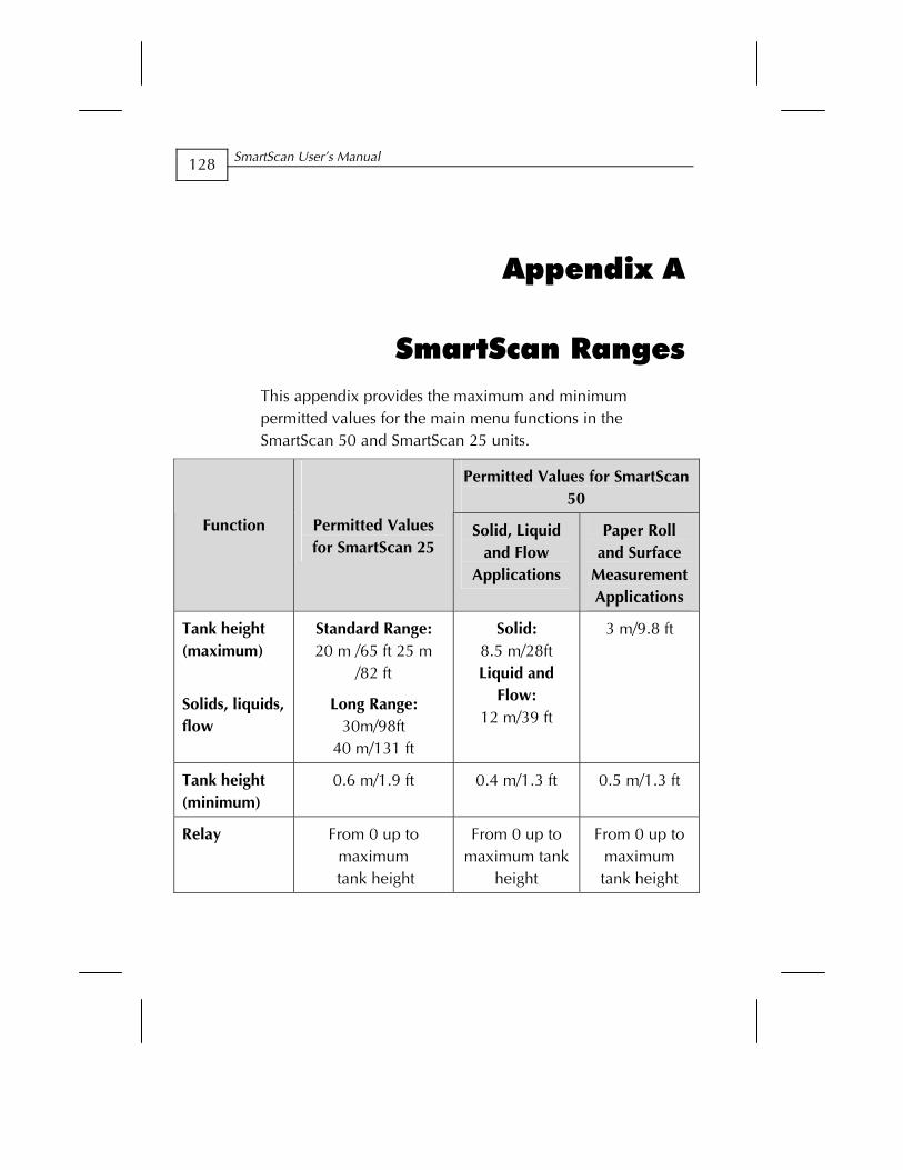
SmartScan User’s Manual
128
Appendix A
SmartScan Ranges This appendix provides the maximum and minimum permitted values for the main menu functions in the SmartScan 50 and SmartScan 25 units.
Permitted Values for SmartScan 50
Function Permitted Values for SmartScan 25
Solid, Liquid and Flow
Applications
Paper Roll and Surface
Measurement Applications
Tank height (maximum)
Solids, liquids, flow
Standard Range: 20 m /65 ft 25 m
/82 ft
Long Range: 30m/98ft
40 m/131 ft
Solid: 8.5 m/28ft Liquid and
Flow: 12 m/39 ft
3 m/9.8 ft
Tank height (minimum)
0.6 m/1.9 ft
0.4 m/1.3 ft
0.5 m/1.3 ft
Relay From 0 up to maximum
tank height
From 0 up to maximum tank
height
From 0 up to maximum tank height
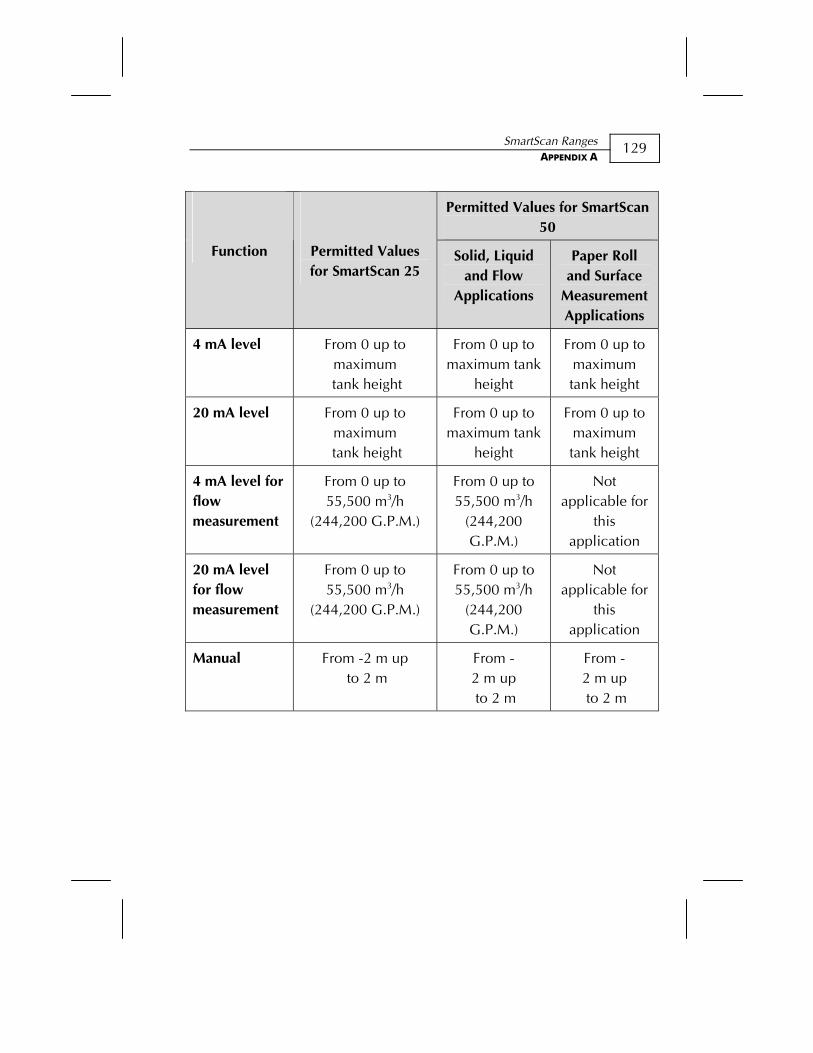
SmartScan Ranges APPENDIX A
129
Permitted Values for SmartScan 50
Function Permitted Values for SmartScan 25
Solid, Liquid and Flow
Applications
Paper Roll and Surface
Measurement Applications
4 mA level From 0 up to maximum
tank height
From 0 up to maximum tank
height
From 0 up to maximum tank height
20 mA level From 0 up to maximum
tank height
From 0 up to maximum tank
height
From 0 up to maximum tank height
4 mA level for flow measurement
From 0 up to 55,500 m3/h
(244,200 G.P.M.)
From 0 up to 55,500 m3/h
(244,200 G.P.M.)
Not applicable for
this application
20 mA level for flow measurement
From 0 up to 55,500 m3/h
(244,200 G.P.M.)
From 0 up to 55,500 m3/h
(244,200 G.P.M.)
Not applicable for
this application
Manual From -2 m up to 2 m
From - 2 m up to 2 m
From - 2 m up to 2 m
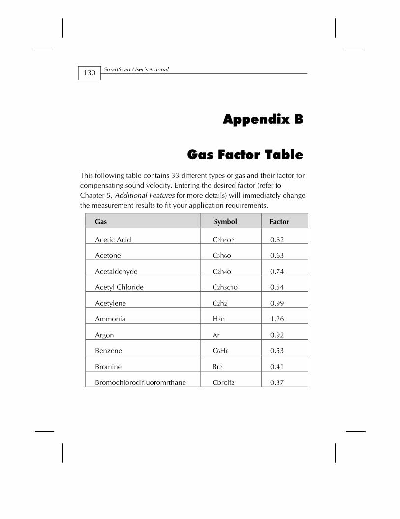
SmartScan User’s Manual
130
Appendix B
Gas Factor Table This following table contains 33 different types of gas and their factor for compensating sound velocity. Entering the desired factor (refer to Chapter 5, Additional Features for more details) will immediately change the measurement results to fit your application requirements.
Factor Symbol Gas
0.62 C2h4o2 Acetic Acid
0.63 C3h6o Acetone
0.74 C2h4o Acetaldehyde
0.54 C2h3c1o Acetyl Chloride
0.99 C2h2 Acetylene
1.26 H3n Ammonia
0.92 Ar Argon
0.53 C6H6 Benzene
0.41 Br2 Bromine
0.37 Cbrclf2 Bromochlorodifluoromrthane
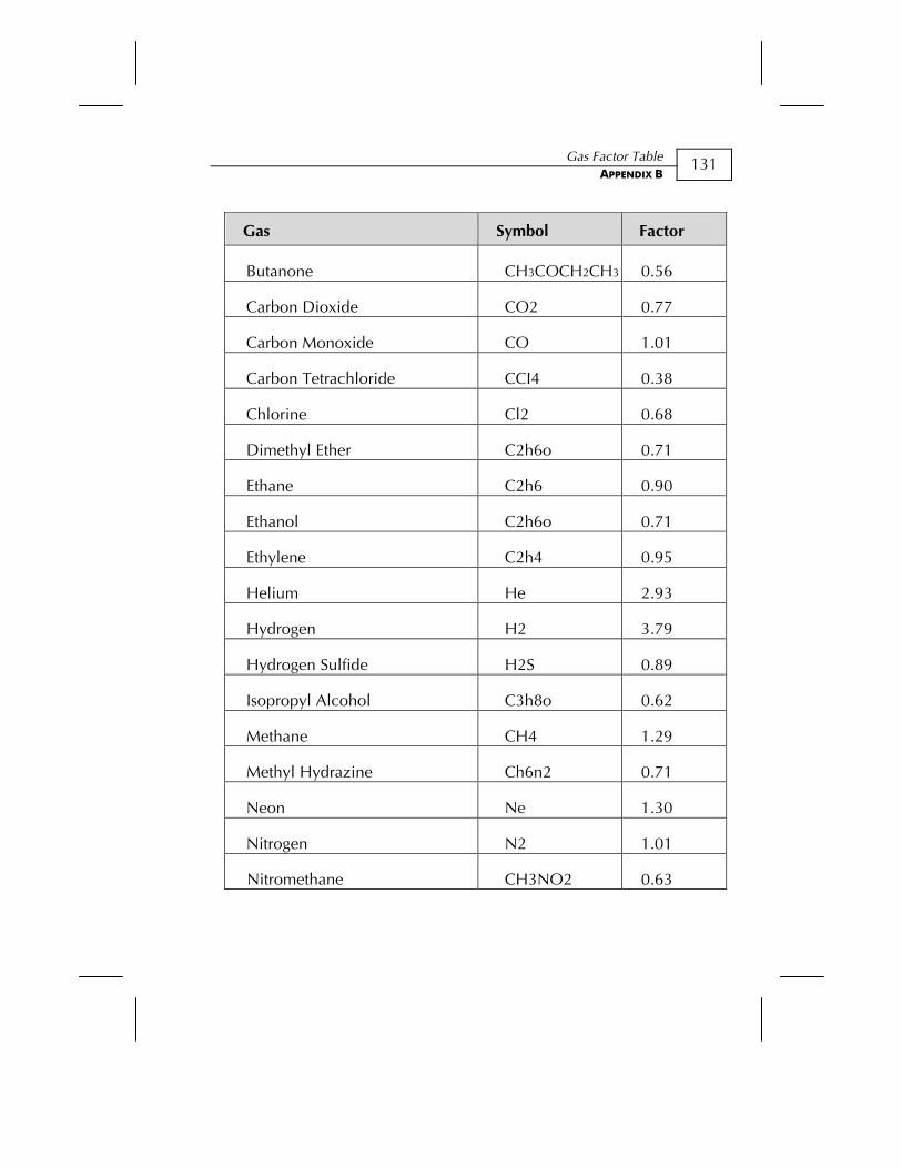
Gas Factor Table APPENDIX B
131
Factor Symbol Gas
0.56 CH3COCH2CH3Butanone
0.77 CO2 Carbon Dioxide
1.01 CO Carbon Monoxide
0.38 CCI4 Carbon Tetrachloride
0.68 Cl2 Chlorine
0.71 C2h6o Dimethyl Ether
0.90 C2h6 Ethane
0.71 C2h6o Ethanol
0.95 C2h4 Ethylene
2.93 He Helium
3.79 H2 Hydrogen
0.89 H2S Hydrogen Sulfide
0.62 C3h8o Isopropyl Alcohol
1.29 CH4 Methane
0.71 Ch6n2 Methyl Hydrazine
1.30 Ne Neon
1.01 N2 Nitrogen
0.63 CH3NO2 Nitromethane
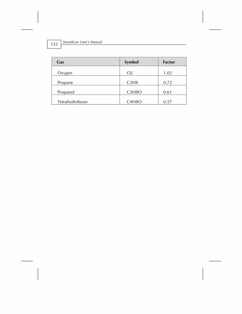
SmartScan User’s Manual
132
Factor Symbol Gas
1.02 O2 Oxygen
0.72 C3H8 Propane
0.61 C3H8O Propanol
0.57 C4H8O Tetrahydrofuran
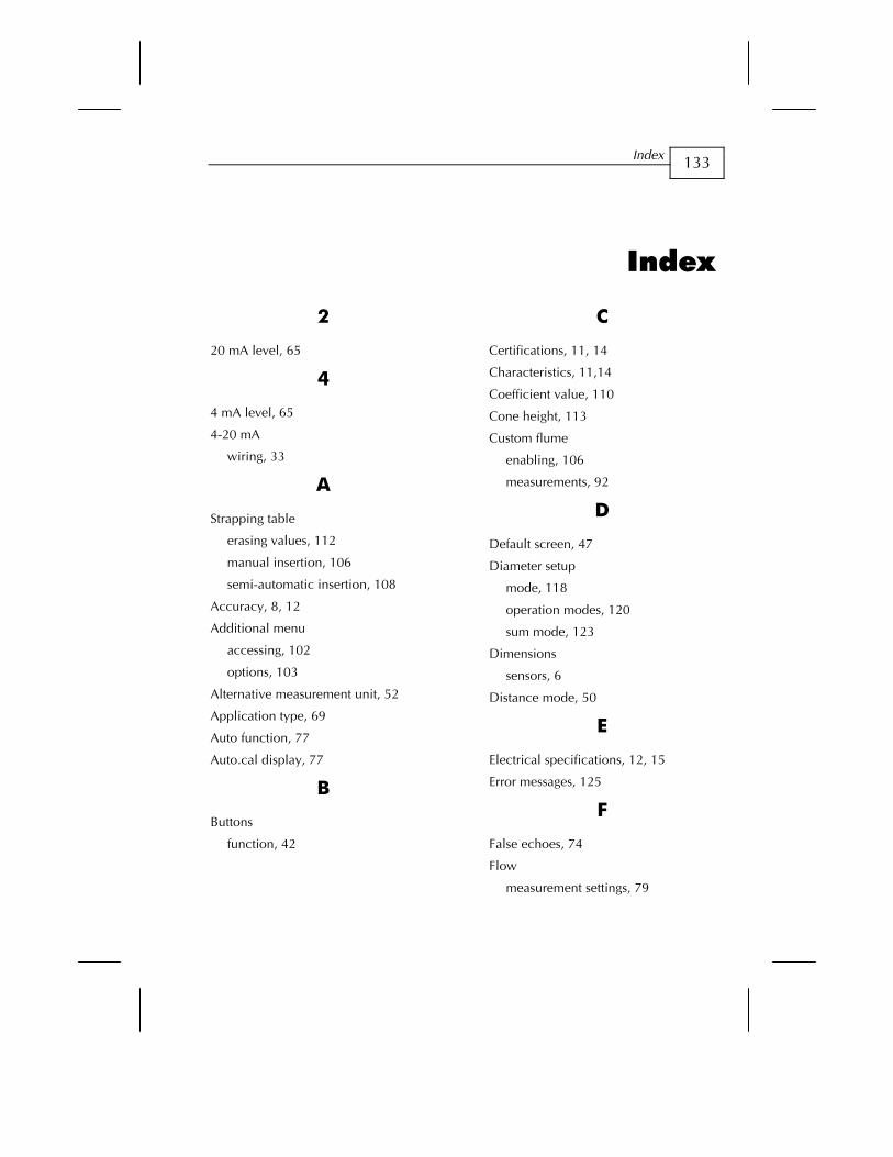
Index
133
Index
2
20 mA level, 65
4
4 mA level, 65
4-20 mA
wiring, 33
A
Strapping table
erasing values, 112
manual insertion, 106
semi-automatic insertion, 108
Accuracy, 8, 12
Additional menu
accessing, 102
options, 103
Alternative measurement unit, 52
Application type, 69
Auto function, 77
Auto.cal display, 77
B
Buttons
function, 42
C
Certifications, 11, 14
Characteristics, 11,14
Coefficient value, 110
Cone height, 113
Custom flume
enabling, 106
measurements, 92
D
Default screen, 47
Diameter setup
mode, 118
operation modes, 120
sum mode, 123
Dimensions
sensors, 6
Distance mode, 50
E
Electrical specifications, 12, 15
Error messages, 125
F
False echoes, 74
Flow
measurement settings, 79
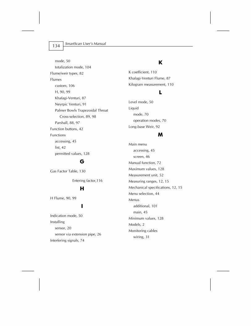
SmartScan User’s Manual
134
mode, 50
totalization mode, 104
Flume/weir types, 82
Flumes
custom, 106
H, 90, 99
Khafagi-Venturi, 87
Neyrpic Venturi, 91
Palmer Bowls Trapezoidal Throat
Cross-selection, 89, 98
Parshall, 88, 97
Function buttons, 42
Functions
accessing, 45
list, 42
permitted values, 128
G
Gas Factor Table, 130
Entering factor,116
H
H Flume, 90, 99
I
Indication mode, 50
Installing
sensor, 20
sensor via extension pipe, 26
Interfering signals, 74
K
K coefficient, 110
Khafagi-Venturi Flume, 87
Kilogram measurement, 110
L
Level mode, 50
Liquid
mode, 70
operation modes, 70
Long-base Weir, 92
M
Main menu
accessing, 45
screen, 46
Manual function, 72
Maximum values, 128
Measurement unit, 52
Measuring ranges, 12, 15
Mechanical specifications, 12, 15
Menu selection, 44
Menus
additional, 101
main, 45
Minimum values, 128
Models, 2
Monitoring cables
wiring, 31

Index
135
N
Neyrpic Venturi Flume, 91
O
Open channels
flow measurements, 81
flume/weir code methodology, 81
flume/weir types, 82
measurement settings, 79
Operation modes
liquid, 70
setting, 70
solid, 71
P
Palmer Bowlus Flume Trapezoidal
Throat Cross-selection, 89, 98
Parsh.flum, 106
Parshall Flume, 88, 97
Power cable
wiring, 33
Precautions, 19
Process option, 70
Processor information
viewing, 77
R
Ranges for functions, 128
Rectangular Contracted Sharp-crested
Weir, 84, 94
Rectangular Supressed Sharp-crested
Weir, 83, 93
Relays
setting values, 54
wiring, 32
RS-232
wiring, 31
RS-485
wiring, 31
S
Scan distance
clearing values, 74
setting values, 74
Sensor deviation, 72
Sensors
cable wiring, 29
dimensions, 6
installing, 20
installing via extension pipe, 26
positioning, 24
recommended types, 15
specifications, 12, 15
threading options, 21
Sharp-crested Weir
Rectangular Contracted, 84, 94
Rectangular Suppressed, 83, 93
Trapezoidal (Cipolletti), 85, 95
V-notch (Triangular), 86
SmartScan
additional functions setup, 103
basic setup, 40
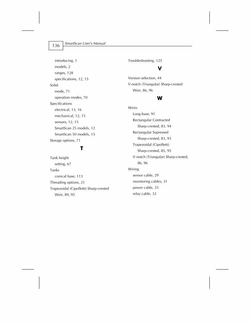
SmartScan User’s Manual
136
introducing, 1 Troubleshooting, 125
models, 2 V ranges, 128
Version selection, 44 specifications, 12, 15 V-notch (Triangular) Sharp-crested
Weir, 86, 96 Solid
mode, 71
W operation modes, 70
Specifications Weirs electrical, 13, 16
Long-base, 91 mechanical, 12, 15 Rectangular Contracted
Sharp-crested, 83, 94 sensors, 12, 15
SmartScan 25 models, 12 Rectangular Supressed
Sharp-crested, 83, 93 SmartScan 50 models, 15
Storage options, 71 Trapezoidal (Cipolletti)
Sharp-crested, 85, 95 T V-notch (Triangular) Sharp-crested,
86, 96 Tank height
setting, 67 Wiring Tanks
sensor cable, 29 conical base, 113 monitoring cables, 31 Threading options, 21 power cable, 33 Trapezoidal (Cipolletti) Sharp-crested
Weir, 89, 95 relay cable, 32