Embed Size (px)
Citation preview

SMB Booster set
SMB../SVE, SMB../VME, SMB../HME
Installation, Operation and Maintenance Manual
Cod.001086038EN rev.C ed.03/2018

en – Original instructions
2
Table of Contents
1 Introduction and Safety ............................................................................................................................................ 5
1.1 Introduction ........................................................................................................................................................ 5
1.2 Safety ................................................................................................................................................................ 5
1.2.1 Danger levels and safety symbols ................................................................................................................ 5
1.2.2 User safety .................................................................................................................................................... 6
1.2.3 General safety rules ...................................................................................................................................... 7
1.2.4 Protection of the environment ....................................................................................................................... 8
1.2.5 Sites exposed to ionizing radiations .............................................................................................................. 8
1.3 Spare parts ........................................................................................................................................................ 8
1.4 Product warranty ............................................................................................................................................... 8
2 Transportation and Storage ..................................................................................................................................... 9
2.1 Handling the booster set ................................................................................................................................... 9
2.2 Storage ............................................................................................................................................................ 10
3 Technical Description ............................................................................................................................................. 11
3.1 Designation ..................................................................................................................................................... 11
3.2 Data plates ...................................................................................................................................................... 11
3.2.1 Booster set .................................................................................................................................................. 11
3.2.2 Distribution panel ......................................................................................................................................... 12
3.3 Design and layout............................................................................................................................................ 13
3.4 Intended use .................................................................................................................................................... 14
3.4.1 Application alternatives ............................................................................................................................... 14
3.5 Improper use ................................................................................................................................................... 14
4 Installation ............................................................................................................................................................... 15
4.1 Mechanical installation .................................................................................................................................... 15
4.1.1 Installation area ........................................................................................................................................... 15
4.1.2 Guidelines for mechanical installation ......................................................................................................... 16
4.2 Hydraulic installation ....................................................................................................................................... 16
4.2.1 Guidelines for hydraulic installation ............................................................................................................. 17
4.3 Electrical Installation ....................................................................................................................................... 18
4.3.1 Electrical requirements ................................................................................................................................ 18
4.3.2 Electrical connection checklist .................................................................................................................... 18
4.3.3 Electrical control panel check-list ................................................................................................................ 18
4.3.4 Wire types and ratings................................................................................................................................. 19
4.3.5 Protection against dry running .................................................................................................................... 20
5 Use and operation .................................................................................................................................................. 21
5.1 Wait times ........................................................................................................................................................ 21
5.2 Starting and stopping ...................................................................................................................................... 21
5.2.1 Adjusting the frequency converter ............................................................................................................... 22
5.2.2 Pre-charging the diaphragm pressure tank ................................................................................................. 22

en – Original instructions
3
5.2.3 Starting the booster set ............................................................................................................................... 22
6 Maintenance ........................................................................................................................................................... 24
6.1 Maintenance of the control panel and frequency converters .......................................................................... 24
6.2 Maintenance of the diaphragm pressure tank ................................................................................................. 24
7 Troubleshooting ...................................................................................................................................................... 25
7.1 The booster set is off ....................................................................................................................................... 25
7.2 Motor does not start ........................................................................................................................................ 25
7.3 Frequent start-ups and stops .......................................................................................................................... 25
7.4 The speed of the pump unit increases and decreases without stopping and without consumption of water (utility closed) ............................................................................................................................................................... 25
7.5 The motor runs but no water is delivered ........................................................................................................ 26
7.6 Loss of water from the pump unit .................................................................................................................... 26
7.7 Too noisy ......................................................................................................................................................... 26
7.8 The booster set does not generate the required pressure .............................................................................. 26
7.9 Tripping of the main protection system (fuses) ............................................................................................... 26
7.10 Tripping of the differential protection ............................................................................................................... 27
7.11 The pump unit runs at maximum speed without stopping .............................................................................. 27
7.12 Only one pump unit is running ........................................................................................................................ 27
7.13 There is demand for water but the pump unit does not start .......................................................................... 27
8 Technical Data ....................................................................................................................................................... 28
8.1 Dimensions and weights ................................................................................................................................. 29
9 Declarations ............................................................................................................................................................. 29
9.1 EC Declaration of Conformity (Original) .......................................................................................................... 29
9.2 EU Declaration of Conformity (No EMCD23) .................................................................................................. 29

en – Original instructions
4
en – Original instructions
5
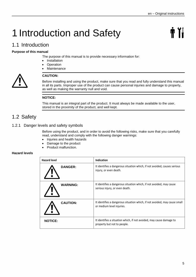
1 Introduction and Safety 1.1 Introduction
Purpose of this manual
The purpose of this manual is to provide necessary information for:
Installation
Operation
Maintenance
CAUTION:
Before installing and using the product, make sure that you read and fully understand this manual in all its parts. Improper use of the product can cause personal injuries and damage to property, as well as making the warranty null and void.
NOTICE:
This manual is an integral part of the product. It must always be made available to the user, stored in the proximity of the product, and well kept.
1.2 Safety
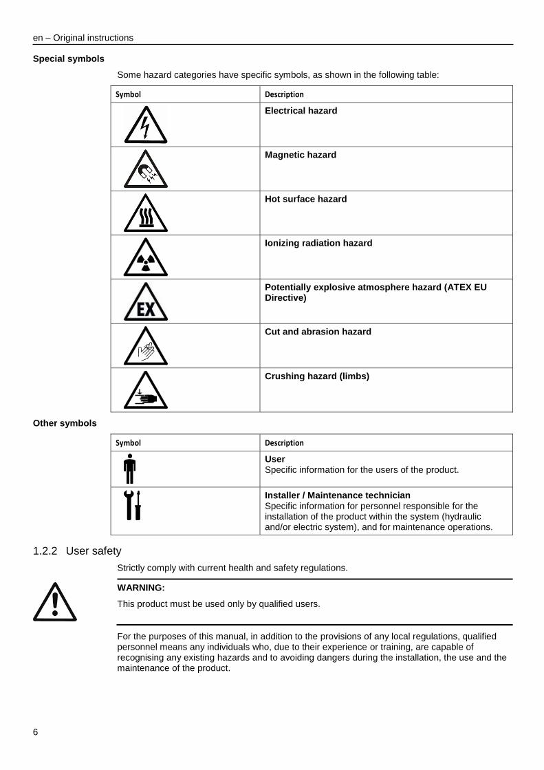
1.2.1 Danger levels and safety symbols
Before using the product, and in order to avoid the following risks, make sure that you carefully read, understand and comply with the following danger warnings:
Injuries and health hazards
Damage to the product
Product malfunction.
Hazard levels
Hazard level Indication
DANGER:
It identifies a dangerous situation which, if not avoided, causes serious injury, or even death.
WARNING:
It identifies a dangerous situation which, if not avoided, may cause serious injury, or even death.
CAUTION:
It identifies a dangerous situation which, if not avoided, may cause small or medium level injuries.
NOTICE:
It identifies a situation which, if not avoided, may cause damage to property but not to people.
en – Original instructions
6
Special symbols
Some hazard categories have specific symbols, as shown in the following table:
Symbol Description
Electrical hazard
Magnetic hazard
Hot surface hazard
Ionizing radiation hazard
Potentially explosive atmosphere hazard (ATEX EU Directive)
Cut and abrasion hazard
Crushing hazard (limbs)
Other symbols
Symbol Description
User Specific information for the users of the product.
Installer / Maintenance technician Specific information for personnel responsible for the installation of the product within the system (hydraulic and/or electric system), and for maintenance operations.
1.2.2 User safety
Strictly comply with current health and safety regulations.
WARNING:
This product must be used only by qualified users.
For the purposes of this manual, in addition to the provisions of any local regulations, qualified personnel means any individuals who, due to their experience or training, are capable of recognising any existing hazards and to avoiding dangers during the installation, the use and the maintenance of the product.

en – Original instructions
7
Inexperienced users
WARNING:
FOR THE EUROPEAN UNION
This appliance can be used by children aged from 8 years and above and persons with reduced physical, sensory or mental capabilities or lack of experience and knowledge if they have been given supervision or instruction concerning use of the appliance in a safe way and understand the hazards involved.
Children shall not play with the appliance.
Cleaning and user maintenance shall not be made by children without supervision. FOR OTHER COUNTRIES
This appliance is not intended for use by persons (including children) with reduced physical, sensory or mental capabilities, or lack of experience and knowledge, unless they have been given supervision or instruction concerning use of the appliance by a person responsible for their safety.
Children should be supervised to ensure that they do not play with the appliance.
1.2.3 General safety rules
WARNING:
Always keep the work area clean.
Pay attention to the risks presented by gas and vapors in the work area.
Always bear in mind the risk of drowning, electrical accidents, and burn injuries.
DANGER: Electrical hazard
Avoid all electric dangers; pay attention to the risk of electric shock or electric arcs
Unintended rotation of motors creates voltage and can charge the unit, resulting in death, serious injury, or equipment damage. Ensure that motors are blocked to prevent unintended rotation.
Magnetic fields
The removal or installation of the rotor in the motor casing generates a strong magnetic field.
DANGER: Magnetic hazard
The magnetic field may be dangerous for anyone wearing peacemakers, or any other medical devices sensitive to magnetic fields.
NOTE
The magnetic field may attract metal debris on the rotor surface, causing damage to the same.
Electrical connections
DANGER: Electrical hazard
The connection to the electric power supply must be completed by an electrician possessing the technical-professional requirements outlined in the current regulations
Precautions before work
WARNING:
Install a suitable barrier around the working area, for example a guard rail
Make sure that all safety guards are in place and secure.
Make sure that you have a clear path of retreat.
Make sure that the product cannot roll or fall over and injure people or damage property.
Make sure that the lifting equipment is in good condition.
Use a lifting harness, a safety line, and a breathing device as required.
en – Original instructions
8
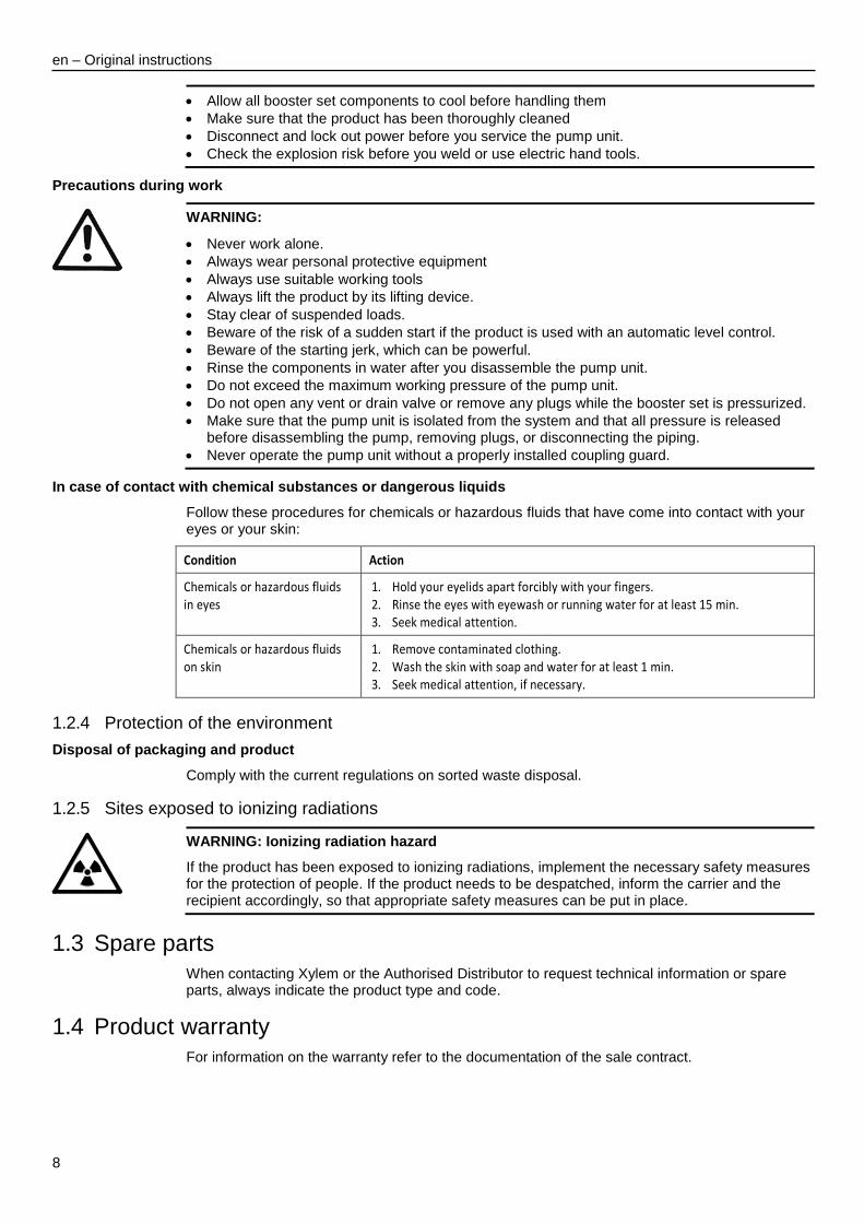
Allow all booster set components to cool before handling them
Make sure that the product has been thoroughly cleaned
Disconnect and lock out power before you service the pump unit.
Check the explosion risk before you weld or use electric hand tools.
Precautions during work
WARNING:
Never work alone.
Always wear personal protective equipment
Always use suitable working tools
Always lift the product by its lifting device.
Stay clear of suspended loads.
Beware of the risk of a sudden start if the product is used with an automatic level control.
Beware of the starting jerk, which can be powerful.
Rinse the components in water after you disassemble the pump unit.
Do not exceed the maximum working pressure of the pump unit.
Do not open any vent or drain valve or remove any plugs while the booster set is pressurized.
Make sure that the pump unit is isolated from the system and that all pressure is released before disassembling the pump, removing plugs, or disconnecting the piping.
Never operate the pump unit without a properly installed coupling guard.
In case of contact with chemical substances or dangerous liquids
Follow these procedures for chemicals or hazardous fluids that have come into contact with your eyes or your skin:
Condition Action
Chemicals or hazardous fluids in eyes
1. Hold your eyelids apart forcibly with your fingers. 2. Rinse the eyes with eyewash or running water for at least 15 min. 3. Seek medical attention.
Chemicals or hazardous fluids on skin
1. Remove contaminated clothing. 2. Wash the skin with soap and water for at least 1 min. 3. Seek medical attention, if necessary.
1.2.4 Protection of the environment
Disposal of packaging and product
Comply with the current regulations on sorted waste disposal.
1.2.5 Sites exposed to ionizing radiations
WARNING: Ionizing radiation hazard
If the product has been exposed to ionizing radiations, implement the necessary safety measures for the protection of people. If the product needs to be despatched, inform the carrier and the recipient accordingly, so that appropriate safety measures can be put in place.
1.3 Spare parts
When contacting Xylem or the Authorised Distributor to request technical information or spare parts, always indicate the product type and code.
1.4 Product warranty
For information on the warranty refer to the documentation of the sale contract.

en – Original instructions
9
2 Transportation and Storage Packaging inspection
1. Check that quantity, descriptions and product codes match the order. 2. Check the packaging for any damage or missing components. 3. In case of immediately detectable damage or missing parts:
Accept the goods with reserve, indicating any findings on the transport document, or
Reject the goods, indicating the reason on the transport document. In both cases, promptly contact Xylem or the Authorised Distributor from whom the product was purchased.
Unpacking and inspection of the product
1. Remove the packaging material from the product. 2. Release the product by removing the screws and/or cutting the straps, if fitted.
CAUTION: Cut and abrasion hazard
Always wear personal protective equipment.
3. Check the product for integrity and to make sure that there are no missing components. 4. In case of damage or missing components, promptly contact Xylem or the Authorised
Distributor.
2.1 Handling the booster set
The booster set must be harnessed and lifted as shown in Figure 1.
WARNING: Crushing hazard (limbs)
The product and its components may be heavy: risk of crushing
Always wear personal protective equipment
Manual handling of the product and its components must be in compliance with the current regulations on "manual load handling", to avoid unfavourable ergonomic conditions causing risks of back-spine injury.
Use cranes, ropes, lifting straps, hooks and clasps that comply with current regulations and that are suitable for the specific use
Make sure that the harnessing does not damage the booster set
During the lifting operations, always avoid sudden movements that could compromise the stability of the load
During handling, make sure to avoid injury to people and animals, and/or damage to property.

en – Original instructions
10
Figure 1: Lifting
2.2 Storage
The product must be stored:
In a covered and dry place
Away from heat sources
Protected from dirt
Protected from vibrations
At an ambient temperature between -25°C and +55°C (-13°F and 131°F), and relative humidity between 5% and 95%.
NOTICE:
Do not place heavy loads on top of the product
Protect the product from collisions.
SMB_M0001_B_sc
en – Original instructions
11
3 Technical Description 3.1 Designation
Booster set consisting of one (SMB10) or more identical variable speed vertical or horizontal multistage non-self priming pump units (SMB20, SMB30) connected in parallel.
The pump units are mounted on a shared base with suction and delivery manifolds, on-off valves, non-return valves, pressure gauge, pressure transmitters and a single-phase or three-phase control panel. A booster set with one pump unit (SMB10) does not come with a control panel and it may not have a base. There are 1" couplings on the delivery manifold for installing diaphragm pressure tanks with an on-off valve. The manifold, like the tanks, requires appropriate support. Additional diaphragm pressure tanks can be installed and connected to the manifold.
3.2 Data plates
The data plate is a label showing:
The main product details
Identification code
Approval and certifications
For the approvals see the booster set data plate:
only
3.2.1 Booster set
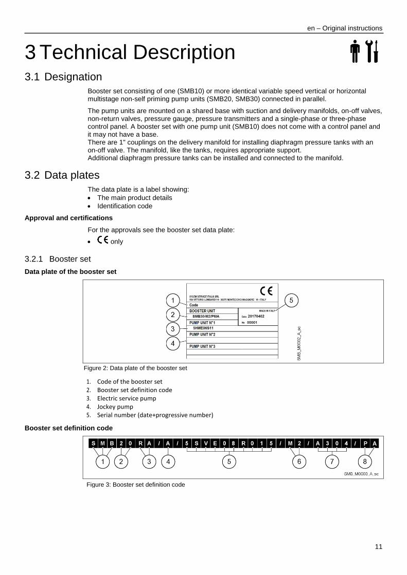
Data plate of the booster set
Figure 2: Data plate of the booster set
1. Code of the booster set 2. Booster set definition code 3. Electric service pump 4. Jockey pump 5. Serial number (date+progressive number)
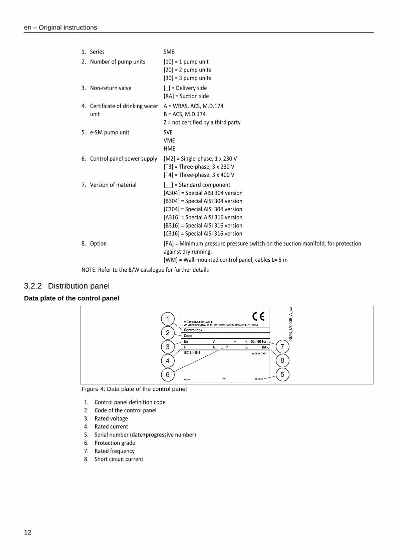
Booster set definition code
Figure 3: Booster set definition code
en – Original instructions
12
1. Series SMB
2. Number of pump units [10] = 1 pump unit [20] = 2 pump units [30] = 3 pump units
3. Non-return valve [_] = Delivery side [RA] = Suction side
4. Certificate of drinking water unit
A = WRAS, ACS, M.D.174 B = ACS, M.D.174 Z = not certified by a third party
5. e-SM pump unit SVE VME HME
6. Control panel power supply [M2] = Single-phase, 1 x 230 V [T3] = Three-phase, 3 x 230 V [T4] = Three-phase, 3 x 400 V
7. Version of material [__] = Standard component [A304] = Special AISI 304 version [B304] = Special AISI 304 version [C304] = Special AISI 304 version [A316] = Special AISI 316 version [B316] = Special AISI 316 version [C316] = Special AISI 316 version
8. Option [PA] = Minimum pressure pressure switch on the suction manifold, for protection against dry running. [WM] = Wall-mounted control panel; cables L= 5 m
NOTE: Refer to the B/W catalogue for further details
3.2.2 Distribution panel
Data plate of the control panel
Figure 4: Data plate of the control panel
1. Control panel definition code 2. Code of the control panel 3. Rated voltage 4. Rated current 5. Serial number (date+progressive number) 6. Protection grade 7. Rated frequency 8. Short circuit current

en – Original instructions
13
3.3 Design and layout
Booster set in standard configuration
Figure 5: Booster set
Position number
Description Q.ty
1. Distribution panel 1
2. E series pump units (e-SM units) n
3. Base 1
4. Priming connection 1
5. Anti-vibration foot 2 x n
6. Suction manifold 1
7. On-off valve on suction line n
8. Non-return valve n
9. On-off valve on delivery line n
10. Pressure sensor n
11. Pressure gauge 1
12. Diaphragm pressure tank connection 1/2/3
13. Delivery manifold 1
14. Mounting bracket 1
Frequency converter
Refer to the Installation, Operation and Maintenance Manual of the pump units in the Smart Pump Range.
en – Original instructions
14
3.4 Intended use
The product can be used to pump:
Cold water
Hot water
Always observe the limits indicated in the Technical Data chapter.
The variable speed pump units installed in the SMB booster sets are suitable for the following applications:
Pressure, level, and flow regulation (open loop systems)
Single or multi pump unit irrigation systems.
3.4.1 Application alternatives
Actuator (constant speed)
The unit operates as an actuator according to speed set point; this is done through user interface, the corresponding analog input or the communication bus.
Controller (constant pressure)
This mode is set as the default operating mode, and is used for units that run with a single pump unit.
Cascade serial / Cascade synchronous
The units are connected via the RS485 interface and communicate via the provided protocol. The combination of the different units which are used in a multi-pump system depends on the system requirements. It is possible to run all the pump units in cascade serial mode (default mode for multi pump systems) and synchronous mode as well. If one unit fails, then each pump unit of the booster set can become the lead pump unit and can take control.
3.5 Improper use
The product must not be used in closed circuit systems where the difference in pressure between two points of the system, generally the delivery and suction of the booster set, is controlled by two sensors for the purpose of keeping it constant.
en – Original instructions
15
4 Installation 4.1 Mechanical installation
4.1.1 Installation area
DANGER: Potentially explosive atmosphere hazard
The operation of the booster set in environments with potentially explosive atmospheres or with combustible dusts (e.g.: wood dust, flour, sugars and grains) is strictly forbidden.
WARNING:
Always wear personal protective equipment
Always use suitable working tools
When selecting the place of installation and connecting the unit to the hydraulic and electric power supplies, strictly comply with current regulations.
Ensure that the ingress protection rating of the unit (IP 55, type 1) is suitable for the installation environment.
CAUTION:
Input protection: to ensure the IP55 (type 1) protection index make sure that the unit is closed correctly.
Before opening the terminal box cover, make sure that there is no water in the unit
Make sure that all unused cable glands and cable holes are correctly sealed
Make sure that the plastic cover is correctly closed
Do not leave the terminal box without cover: risk of damage due to contamination
Make sure that the electric panel is correctly closed.
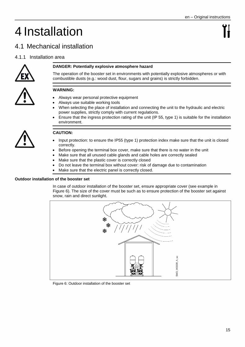
Outdoor installation of the booster set
In case of outdoor installation of the booster set, ensure appropriate cover (see example in Figure 6). The size of the cover must be such as to ensure protection of the booster set against snow, rain and direct sunlight.
Figure 6: Outdoor installation of the booster set
en – Original instructions
16
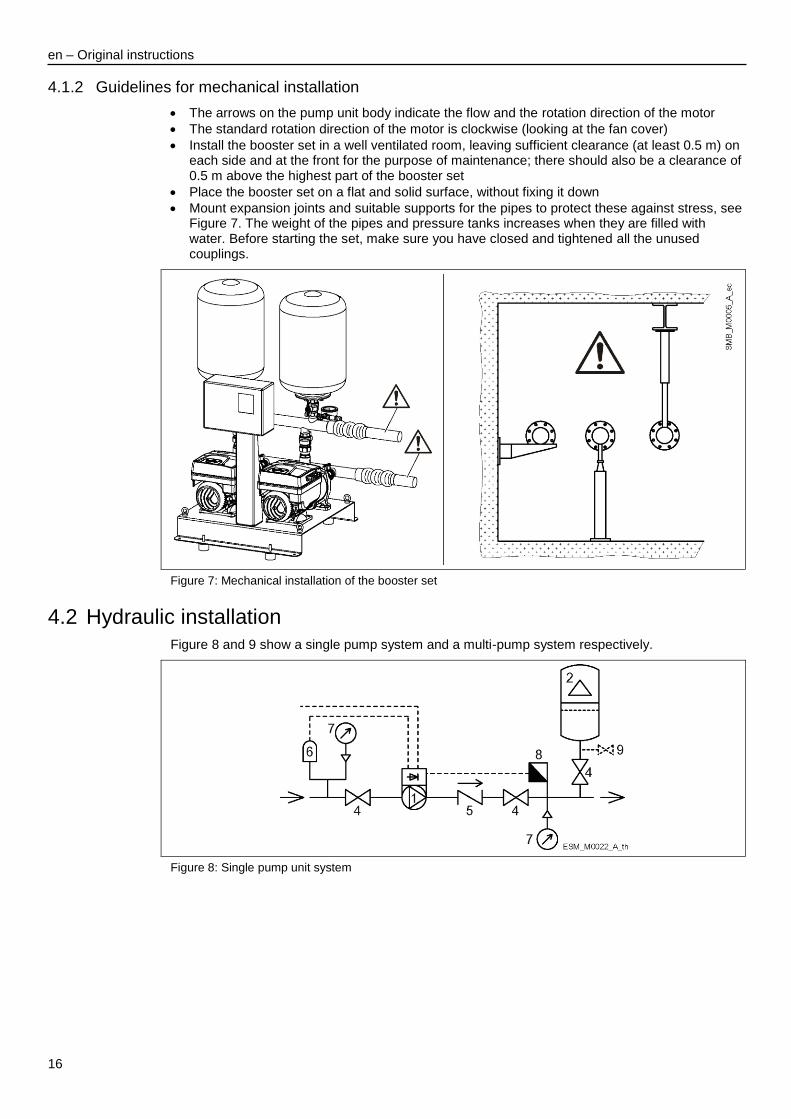
4.1.2 Guidelines for mechanical installation
The arrows on the pump unit body indicate the flow and the rotation direction of the motor
The standard rotation direction of the motor is clockwise (looking at the fan cover)
Install the booster set in a well ventilated room, leaving sufficient clearance (at least 0.5 m) on each side and at the front for the purpose of maintenance; there should also be a clearance of 0.5 m above the highest part of the booster set
Place the booster set on a flat and solid surface, without fixing it down
Mount expansion joints and suitable supports for the pipes to protect these against stress, see Figure 7. The weight of the pipes and pressure tanks increases when they are filled with water. Before starting the set, make sure you have closed and tightened all the unused couplings.
Figure 7: Mechanical installation of the booster set
4.2 Hydraulic installation
Figure 8 and 9 show a single pump system and a multi-pump system respectively.
Figure 8: Single pump unit system

en – Original instructions
17
Figure 9: Multi-pump system
1. e-SM pump unit with motor 2. Diaphragm pressure tank 3. Distribution panel
4. On-off valve 5. Non-return valve 6. Low water control
7. Pressure gauge 8. Pressure sensor 9. Drain tap
4.2.1 Guidelines for hydraulic installation
Install the booster set according to the water flow rate of the system
The arrows on the body of the pump unit indicate the flow and the rotation direction
Install a foot check valve in case of a suction lift system
Install an on-off valve immediately downstream of the booster set
Install a drain valve for the tests if there is no valve next to the booster set
The pipes connected to the booster set must be adequately sized (if possible, according to manifold diameter). You can use either end of the manifold, but don't forget to plug the unused end.
The size of the suction pipe and foot check valve must be such as to avoid excessive load loss and the cavitation phenomena that can be caused as a result
Diaphragm pressure tank
On the delivery side of the pump unit there is a membrane expansion vessel, which gives the possibility of maintaining the pressure inside the piping when the booster set is not being used. The diaphragm pressure tank stops the pump unit from continuing to run at zero demand and reduces the size of the tank that is required for supply purposes. Choose a diaphragm pressure tank suited to the pressure of the system. Variable speed booster sets can operate with diaphragm pressure tanks of smaller sizes than traditional systems. A diaphragm pressure tank with a capacity in litres equivalent to about 10% the flow rate of a single pump unit, expressed in litres per minute. The volume of water required can be distributed between several tanks.

en – Original instructions
18
4.3 Electrical Installation
DANGER: Electrical hazard
The connection to the electric power supply must be completed by an electrician possessing the technical-professional requirements outlined in the current regulations.
For the electrical connections, refer to the wiring diagram in the control panel.
4.3.1 Electrical requirements
Local directives prevail on the specific requirements indicated below.
4.3.2 Electrical connection checklist
Check that the following requirements are met:
The electrical leads are protected from high temperature, vibrations, and collisions.
The current and voltage of the mains power supply must be compatible with the data on the plate of the control panel, or the data on the plate of the pump unit in the case of booster sets without control panel.
Check that the power supply cable is capable of carrying the nominal current of the booster set, and connect it to the relevant terminals of the control panel. The wiring diagram and the labels on the panel provide the necessary information for connection and the required power supply values. For booster sets without control panel, refer to the Installation, Operation and Maintenance Manual of the pump units in the Smart Pump Range.
If there is a control panel, connect the power cable: - Single-phase version to the L-N terminals, PE to the ground terminal - Single-phase version to the L1, L2 and L3 terminals, PE to the ground terminal
Any exposed cables must be protected in an appropriate way
The power supply line is provided with: - A high-sensitivity differential switch (30 mA) [residual current device RCD] suitable for
earth fault currents with DC or pulsating DC content (a Type B RCD is suggested). - A mains isolator switch with a contact gap of at least 3 mm.
4.3.3 Electrical control panel check-list
NOTICE: The standard version of the booster set has a control panel. If the booster set is supplied without a control panel, install a control panel that is compatible with the ratings of the pump unit. Inappropriate combinations do not guarantee the protection of the booster set.
Check that the following requirements are met:
The control panel must protect the pump unit against short-circuit. A time lag fuse or a circuit breaker (Type C model is suggested) can be used to protect the pump unit.
The pump unit has built in overload and thermal protection. No additional overload protection is required.
DANGER: Electrical hazard
Before starting the pressure booster, make sure that the booster set and the control panel are isolated from the power supply and cannot be energized.

en – Original instructions
19
Grounding (earthing)
DANGER: Electrical hazard
Always connect the external protection conductor to the ground terminal before attempting to make any other electrical connections
All the electrical equipment must be grounded (earthed); this includes the booster set and its equipment. Check that the ground terminal is connected properly.
Check that the protection conductor (ground) is longer than the phase conductors; in case of accidental disconnection of the power supply conductor, the protection conductor (ground) must be the last one to detach itself from the terminal.
Keep the connections to the ground cable as short as possible.
Use a cable with several strands to reduce electric noise.
4.3.4 Wire types and ratings
For the standard version with control panel, the booster set is supplied with the power cables of the pump unit and the control cables. The booster set without control panel is supplied with the cable for connecting the pressure sensor but without the power cables of the pump unit. If the power cable of the pump unit and/or the control cables need to be replaced or added, refer to the Installation, Operation and Maintenance Manual of the pump units in the Smart Pump Range.
All cables must comply with local and national standards in terms of section and ambient temperature
Use cables with a minimum heat resistance of +70°C (158°F)
Cables must never enter into contact with the motor body, the pump unit and the piping.
The wires connected to the power supply terminals and the fault signal relay (NO, C) must be separated from the others by means of reinforced insulation.
Power supply connection
WARNING:
Do not make any connection to the terminal board box of the pump unit without first disconnecting the power supply and waiting for the minimum time in Table 1.
The standard version of the booster set is supplied with the power cables of the motor. Replace the power cable of the motor, if necessary, with a cable of a cross-section suited to the maximum consumption of the electric motor.
Control cables
External volt free contacts must be suitable for switching < 10 VDC.
NOTICE:
Install the control cables separate from the power supply cables and the fault signal relay cable
If the control cables are installed in parallel with the power supply cable or the fault signal relay, the distance between the cables must exceed 200 mm
Do not intersect the power supply cables; should this be necessary, a 90°intersection angle is permitted.
Connecting the control panel
Refer to the wiring diagram in the control panel.
Connecting the frequency converter
Refer to the Installation, Operation and Maintenance Manual of the pump units in the Smart Pump Range.

en – Original instructions
20
4.3.5 Protection against dry running
The standard control panel can be connected to a common float for the open tanks, or to a minimum pressure pressure switch on the suction side (recommended value: 0.2-0.4 bar). When the minimum pressure conditions are restored, the pump units start automatically. If the dry running protection is considered to be superfluous, do not remove the jumper on the terminal in the control panel. The correct numbers of the terminals are given in the connection diagram that can be found in the control panel.
NOTICE: The booster set is supplied with the jumper installed and, therefore, without the dry running protection enabled.
The optional electronic level control kit permits control with electrode probes. Install the three probes supplied with the kit in the collection tank and connect them to the terminals in the control panel. The correct numbers of the terminals are given in the wiring diagram that can be found in the panel:
Max probe (A) determines the level at which to activate the booster set during filling of the collection tank.
Min probe (B) determines the level at which to deactivate the booster set.
Probe (C) must be at a level below that of the Min probe (B).

en – Original instructions
21
5 Use and operation In case of co-existance of two or more of the following conditions:
high ambient temperature
high water temperature
duty points insisting on maximum power of the booster set
persisting undervoltage of mains, the life of the booster set may be jeopardised and/or derating may occur: for further information contact Xylem or the Authorised Distributor.
5.1 Wait times
WARNING: Electrical hazard
Contact with electric components may cause death, even after the booster set has been switched off. Before any interventions on the booster set, the network voltage and any other input voltages must be disconnected for the minimum time indicated in Table 1.
Table 1: Wait times
e-SM Drive model Minimum waiting times [min]
103, 105, 107, 111, 115 4
303, 305, 307, 311, 315, 322 5
WARNING: Electrical hazard
Frequency converters contain DC-link capacitors that can remain charged even when the frequency converter is not powered. To avoid electrical hazards:
Disconnect the AC power supply
Disconnect all types of permanent magnet motors
Disconnect all DC-link remote power supplies, including the battery backups, the Uninterrupted Power Supply units and the DC-link connections to other frequency converters
Wait for the capacitors to discharge completely before carrying out any maintenance or repairs; see Table 1 for the waiting times.
5.2 Starting and stopping
Starting and stopping of the pump units depends on the settings of the frequency converter in relation to the pump unit that is to be controlled (pressure, level). Each frequency converter is connected to a sensor. The frequency converters share all the information and implement cycled switching.
Electrical hazard:
Disconnect the power supply before making any adjustments.
For the settings, refer to the Installation, Operation and Maintenance Manual of the pump units in the Smart Pump Range.
en – Original instructions
22
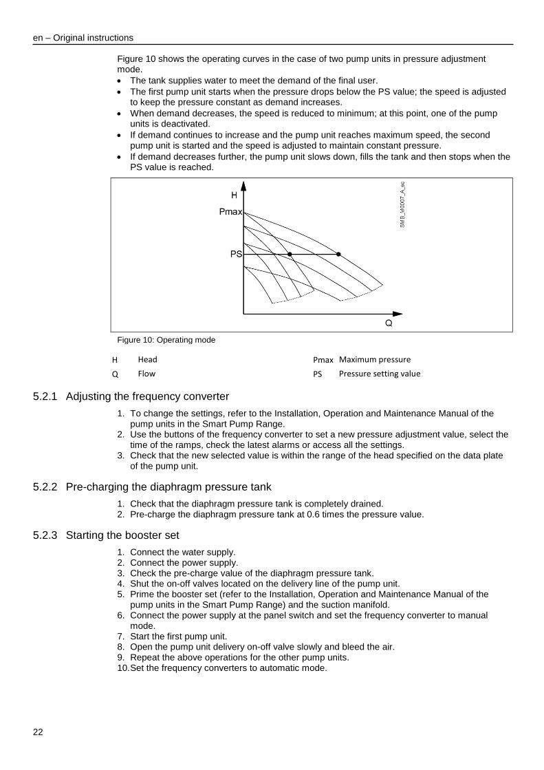
Figure 10 shows the operating curves in the case of two pump units in pressure adjustment mode.
The tank supplies water to meet the demand of the final user.
The first pump unit starts when the pressure drops below the PS value; the speed is adjusted to keep the pressure constant as demand increases.
When demand decreases, the speed is reduced to minimum; at this point, one of the pump units is deactivated.
If demand continues to increase and the pump unit reaches maximum speed, the second pump unit is started and the speed is adjusted to maintain constant pressure.
If demand decreases further, the pump unit slows down, fills the tank and then stops when the PS value is reached.
Figure 10: Operating mode
H Head Pmax Maximum pressure
Q Flow PS Pressure setting value
5.2.1 Adjusting the frequency converter
1. To change the settings, refer to the Installation, Operation and Maintenance Manual of the pump units in the Smart Pump Range.
2. Use the buttons of the frequency converter to set a new pressure adjustment value, select the time of the ramps, check the latest alarms or access all the settings.
3. Check that the new selected value is within the range of the head specified on the data plate of the pump unit.
5.2.2 Pre-charging the diaphragm pressure tank
1. Check that the diaphragm pressure tank is completely drained. 2. Pre-charge the diaphragm pressure tank at 0.6 times the pressure value.
5.2.3 Starting the booster set
1. Connect the water supply. 2. Connect the power supply. 3. Check the pre-charge value of the diaphragm pressure tank. 4. Shut the on-off valves located on the delivery line of the pump unit. 5. Prime the booster set (refer to the Installation, Operation and Maintenance Manual of the
pump units in the Smart Pump Range) and the suction manifold. 6. Connect the power supply at the panel switch and set the frequency converter to manual
mode. 7. Start the first pump unit. 8. Open the pump unit delivery on-off valve slowly and bleed the air. 9. Repeat the above operations for the other pump units. 10. Set the frequency converters to automatic mode.

en – Original instructions
23
How to change the settings
With the booster set running, follow the instructions below on how to change the settings within the maximum pressure limits of the pump units or system or both: 1. Establish the required pressure value. 2. Set the new value using the buttons of the frequency converter; the value is automatically
changed also for the other converter.
en – Original instructions
24
6 Maintenance
DANGER: Electrical hazard
Before attempting to use the unit, check that it is unplugged and that the pump unit and the control panel cannot restart, even unintentionally. This also applies to the auxiliary control circuit of the pump unit.
Before any interventions on the booster set, the network power supply and any other input voltages must be disconnected for the minimum time indicated in the para. Wait Times (the capacitors of the intermediate circuit must be discharged by the built-in discharge resistors).
1. Make sure that the cooling fan and the vents are free from dust. 2. Make sure that the ambient temperature is correct according to the limits of the booster set. 3. Make sure that qualified personnel perform all modifications of the booster set. 4. Make sure that the booster set is disconnected from the power supply before any work is
carried out. 5. Always observe the pump unit and motor instructions.
6.1 Maintenance of the control panel and frequency converters
The control panel and frequency converters do not require maintenance.
6.2 Maintenance of the diaphragm pressure tank
Refer to the Installation, Operation and Maintenance Manual of the diaphragm pressure tank
Check the pre-charge at least once a year.
Function and parameter control
In case of changes to the hydraulic booster set: 1. Make sure that all functions and parameters are correct. 2. Adjust the functions and parameters if necessary.

en – Original instructions
25
7 Troubleshooting Precautions
WARNING:
Faults must be corrected by a technician possessing the technical-professional requirements outlined in the current regulations
Observe the safety requirements in the chapters on Use and Operation and Maintenance
If a fault cannot be corrected or is not mentioned, contact Xylem or the Authorised Distributor.
The frequency converter saves the last alarms that have occurred. Refer to the instructions on use of the frequency converter for the types of fault and how to check the last alarms that have occurred.
7.1 The booster set is off
Cause Remedy
Power supply cut off Restore the power supply
Switch in OFF position Turn the switch ON
7.2 Motor does not start
Cause Remedy
Power supply cut off Restore the power supply
The thermal overload protection of the motor has been triggered
Eliminate the fault and reset the switch
Motor (coil) faulty Check and repair or replace the motor
7.3 Frequent start-ups and stops
Cause Remedy
Diaphragm pressure tank faulty Repair or replace the diaphragm pressure tank
Incorrect pre-charge of the diaphragm pressure tank
Set the new pressure pre-charge value according to the pump unit and setpoint
The pre-charge value of the diaphragm pressure tank is at zero
The diaphragm pressure tank must be pre-charged
7.4 The speed of the pump unit increases and decreases without stopping and without consumption of water (utility closed)
Cause Remedy
Loss of water from the non-return valve
Check the hydraulic system and the valve
The diaphragm pressure tank is damaged or undersized
Repair or replace the diaphragm pressure tank

en – Original instructions
26
7.5 The motor runs but no water is delivered
Cause Remedy
No water on suction side or inside the pump unit
1. Fill (prime) the pump unit or suction pipe 2. Open the on-off valves
Air inside the suction pipe or pump unit
1. Vent the pump unit 2. Check the suction connections
Loss of pressure on the suction side Check the NPSH and, if necessary, modify the system
Non-return valve blocked Clean the valve
Clogged pipe Clean the pipe
7.6 Loss of water from the pump unit
Cause Remedy
Mechanical seal worn or damaged Replace the mechanical seal
Undue mechanical stress on the pump unit
Support the pipes
7.7 Too noisy
Cause Remedy
Return of water when the pump unit is not running
Check the non-return valve
Cavitation Check suction
Rotation of pump unit hindered Check for undue mechanical stress on the pump unit
7.8 The booster set does not generate the required pressure
Cause Remedy
On-off valves closed Open the valves
Air in the suction pipe 1. Eliminate the air 2. Prime the pump units
Excessive negative suction head Decrease the negative suction head
Excessive loss of pressure on the suction side
Increase the diameter of the pipes
Foot check valve damaged Replace the foot valve
Excessive loss of pressure in the delivery pipes and/or in the valve
Reduce the loss of water
7.9 Tripping of the main protection system (fuses)
Cause Remedy
Short circuit 1. Check the connecting cables 2. Check the frequency converter

en – Original instructions
27
7.10 Tripping of the differential protection
Cause Remedy
Damaged motor Replace the motor
Power cable of the motor faulty or worn
Replace the cable
Differential switch not compliant with the specifications
Replace the differential switch
Differential current too high Contact a qualified technician to have the electrical system modified
7.11 The pump unit runs at maximum speed without stopping
Cause Remedy
Pressure setpoint not suitable for the system (the value is higher than the pressure that the pump unit can deliver)
Set the new setpoint according to the performance of the pump unit
Sensor not connected or damaged Check the hydraulic and electrical connection of the sensor
7.12 Only one pump unit is running
Cause Remedy
The pump units have different settings
1. Check setting of the frequency converter 2. Check the serial connection between the two frequency converters
7.13 There is demand for water but the pump unit does not start
Cause Remedy
The setpoint is set at zero 1. Check setting of the frequency converter 2. Set the setpoint
en – Original instructions
28
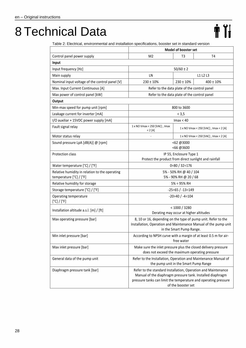
8 Technical Data Table 2: Electrical, environmental and installation specifications, booster set in standard version
Model of booster set
Control panel power supply M2 T3 T4
Input
Input frequency [Hz] 50/60 ± 2
Main supply LN L1 L2 L3
Nominal input voltage of the control panel [V] 230 ± 10% 230 ± 10% 400 ± 10%
Max. Input Current Continuous [A] Refer to the data plate of the control panel
Max power of control panel [kW] Refer to the data plate of the control panel
Output
Min-max speed for pump unit [rpm] 800 to 3600
Leakage current for inverter [mA] < 3,5
I/O auxiliar + 15VDC power supply [mA] Imax < 40
Fault signal relay 1 x NO Vmax < 250 [VAC] , Imax < 2 [A]
1 x NO Vmax < 250 [VAC] , Imax < 2 [A]
Motor status relay - 1 x NO Vmax < 250 [VAC] , Imax < 2 [A]
Sound pressure LpA [dB(A)] @ [rpm] <62 @3000 <66 @3600
Protection class IP 55, Enclosure Type 1 Protect the product from direct sunlight and rainfall
Water temperature [°C] / [°F] 0÷80 / 32÷176
Relative humidity in relation to the operating temperature [°C] / [°F]
5% - 50% RH @ 40 / 104 5% - 90% RH @ 20 / 68
Relative humidity for storage 5% ÷ 95% RH
Storage temperature [°C] / [°F] -25÷65 / -13÷149
Operating temperature [°C] / [°F]
-20÷40 / -4÷104
Installation altitude a.s.l. [m] / [ft] < 1000 / 3280
Derating may occur at higher altitudes
Max operating pressure [bar] 8, 10 or 16, depending on the type of pump unit. Refer to the Installation, Operation and Maintenance Manual of the pump unit
in the Smart Pump Range.
Min inlet pressure [bar] According to NPSH curve with a margin of at least 0.5 m for air-free water
Max inlet pressure [bar] Make sure the inlet pressure plus the closed delivery pressure does not exceed the maximum operating pressure
General data of the pump unit Refer to the Installation, Operation and Maintenance Manual of the pump unit in the Smart Pump Range
Diaphragm pressure tank [bar] Refer to the standard Installation, Operation and Maintenance Manual of the diaphragm pressure tank. Installed diaphragm
pressure tanks can limit the temperature and operating pressure of the booster set
en – Original instructions
29
8.1 Dimensions and weights
Booster set: refer to the technical catalogue or contact Xylem or the Authorised Distributor.
Pump units in the Smart Pump Range: refer to the Installation, Operation and Maintenance Manual.
9 Declarations 9.1 EC Declaration of Conformity (Original)
Xylem Service Italia S.r.l., with headquarters in Via Vittorio Lombardi 14 - 36075 Montecchio Maggiore VI - Italy, hereby declares that the product:
Pumping unit with pump units with integrated variable speed drive (refer to label on first page)
fulfils the relevant provisions of the following European Directives:
Machinery 2006/42/EC (ANNEX II - natural or legal person authorised to compile the technical file: Xylem Service Italia S.r.l.)
and the following technical standards
EN 809:1998+A1:2009,
EN 60204-1:2006+A1:2009
Montecchio Maggiore, 22/02/2017 Amedeo Valente (Director of Engineering and Research & Development)
rev.00
9.2 EU Declaration of Conformity (No EMCD23)
1. Apparatus model/Product: see adhesive on the first page
2. Name and address of the manufacturer: Xylem Service Italia S.r.l. Via Vittorio Lombardi 14 36075 Montecchio Maggiore VI Italy
3. This declaration of conformity is issued under the sole responsibility of the manufacturer. 4. Object of the declaration:
Pumping unit with pump units with integrated variable speed drive (refer to label on first page) 5. The object of the declaration described above is in conformity with the relevant Union
harmonisation legislation: Directive 2014/30/EU of 26 February 2014 (electromagnetic compatibility)
6. References to the relevant harmonised standards used or references to the other technical specifications, in relation to which conformity is declared: EN 61000-6-2:2006, EN 61000-6-3:2007+A1:2011
7. Notified body: - 8. Additional information:
Signed for and on behalf of: Xylem Service Italia S.r.l. Montecchio Maggiore, 22/02/2017 Amedeo Valente (Director of Engineering and Research & Development)
rev.00
Lowara is a trademark of Xylem Inc. or one of its subsidiaries.

en – Original instructions
30

Xylem Service Italia S.r.l.
Via Vittorio Lombardi 14
36075 – Montecchio Maggiore (VI) - Italy
www.xyleminc.com/brands/lowara
Lowara is a trademark of Xylem Inc. or one of its subsidiaries.
© 2017 Xylem, Inc.