Embed Size (px)
DESCRIPTION
Â
Citation preview

Barnum Common SMC Product Guide
1
Silencer
Particulate Filter
Regulator
AFM
Filter/Regulator
Mist Separator
AR..............................................................................Page 6 Micro Mist Filter
AW.............................................................................Page 7
Modular F.R.L. UnitAL ..............................................................................Page 8
Soft Start Lockout
AC .............................................................................Page 9
Pressure Relief 3 Port Valve with Locking Holes
AC...............................................................................Page 10
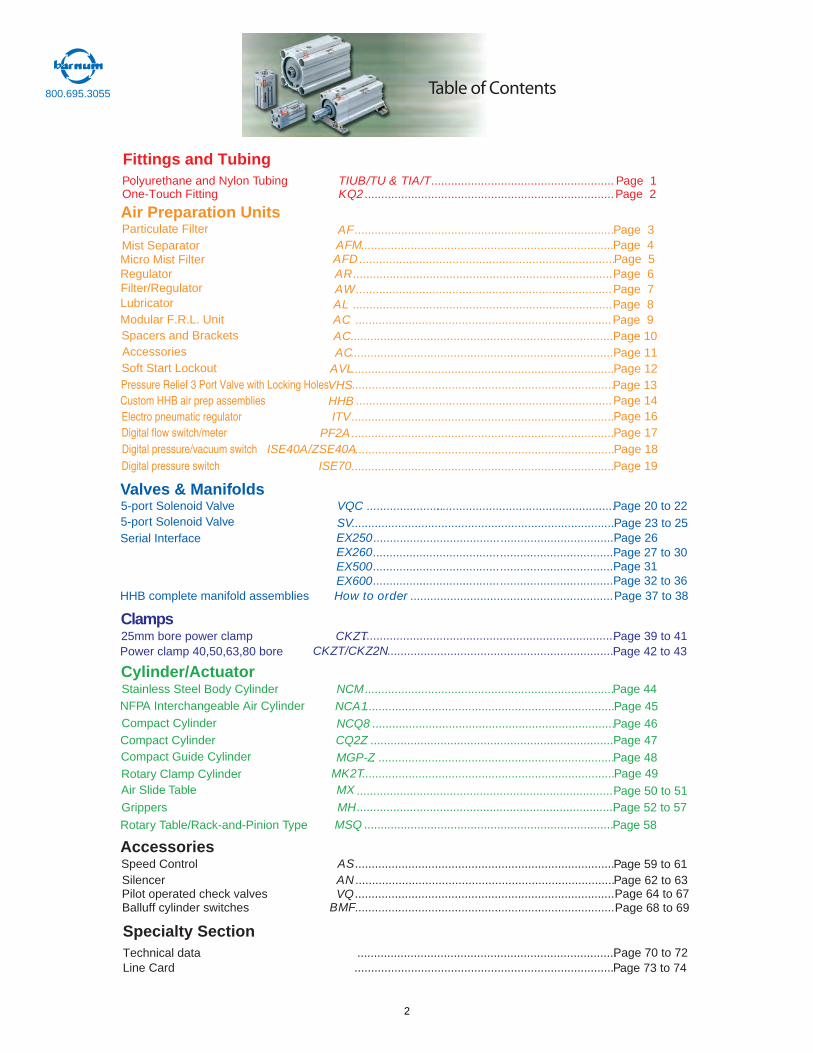
Table of Contents
Air Preparation Units
Polyurethane and Nylon Tubing TIUB/TU & TIA/T....................................................... Page 1 One-Touch Fitting KQ2 ...........................................................................Page 2
AF..............................................................................Page 3............................................................................Page 4
AFD .............................................................................Page 5
Fittings and Tubing
Spacers and BracketsAccessories AC...............................................................................Page 11
AVL...............................................................................
Page 12
HHB .............................................................................Page 14
Lubricator
800.695.3055
Page 13 ...............................................................................
Custom HHB air prep assembliesPage 16ITV...............................................................................Electro pneumatic regulator
Digital flow switch/meter Page 17PF2A...............................................................................Digital pressure/vacuum switch Page 18...............................................................................ISE40A/ZSE40ADigital pressure switch Page 19 ...............................................................................ISE70
Cylinder/ActuatorNCM ...........................................................................Page 44Stainless Steel Body Cylinder
NCA1...........................................................................Page 45
NCQ8 .........................................................................Page 46CQ2Z .........................................................................Page 47
NFPA Interchangeable Air Cylinder
. .......................................................................Page 48
Compact Cylinder
.............................................................................Page 50 to 51
Compact Cylinder
MH Page 52 to 57
Compact Guide Cylinder MGP-Z
..............................................................................
Page 39 to 41
Air Slide Table MX
............................................................................
Page 58
............................................................................Page 49
Rotary Table/Rack-and-Pinion Type MSQ
Rotary Clamp Cylinder MK2T
...........................................................................Grippers
CKZT25mm bore power clampCKZT/CKZ2N Page 42 to 43....................................................................Power clamp 40,50,63,80 bore
Valves & Manifolds5-port Solenoid Valve VQC 22 ot 02 egaP.................................................... ........................5-port Solenoid Valve SV...............................................................................Page 23 to 25
EX250EX260EX500EX600
..................................Page 26Serial Interface
AS ..............................................................................Page 59 to 61AN ..............................................................................Page 62 to 63
HHB complete manifold assemblies How to order ............................................................. age 37 to 38P
Speed ControlAccessories
Pilot operated check valves VQ ..............................................................................Page 64 to 67Balluff cylinder switches BMF
..............................................................................
..............................................................................Page 68 to 69
Technical data Page 70 to 72 Line Card ..............................................................................Page 73 to 74
VHS
Clamps
Specialty Section
........................................................................Page 27 to 30........................................................................Page 31........................................................................Page 32 to 36 ......................................
2
How to Order
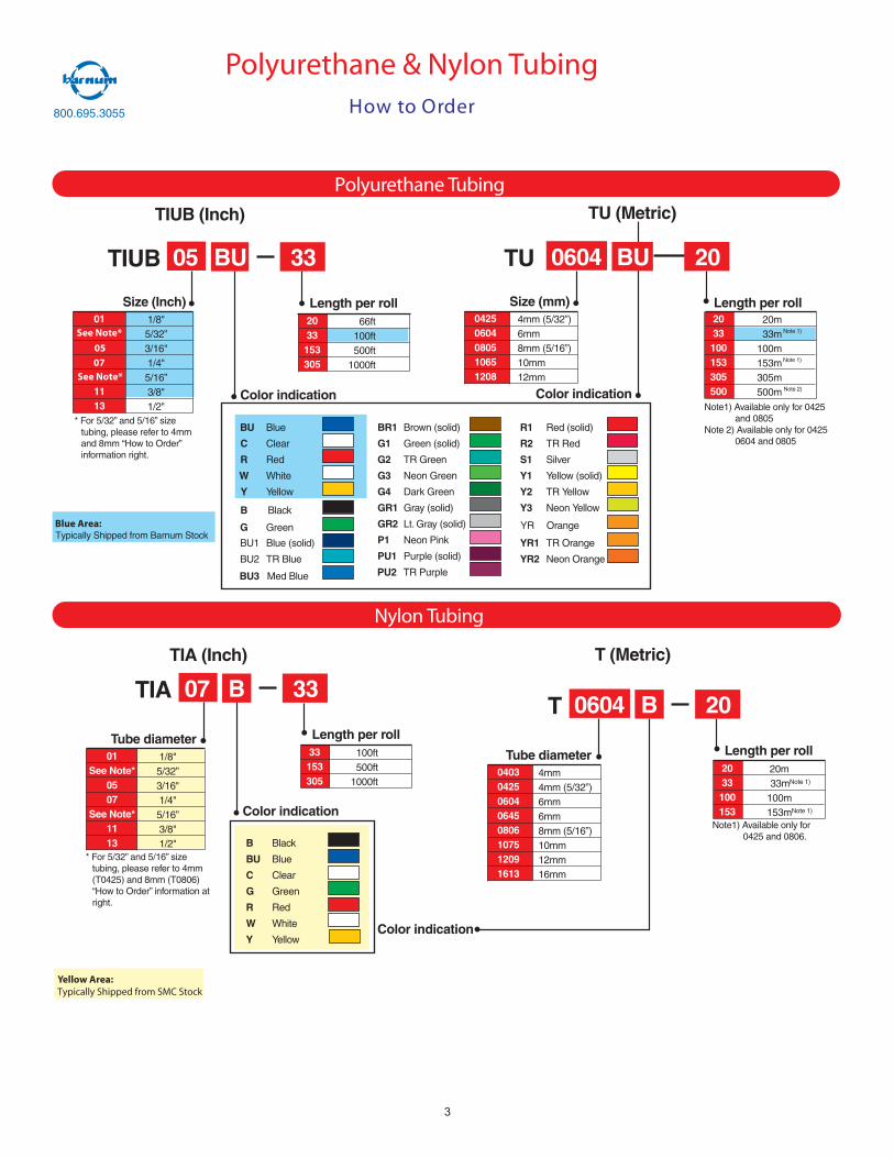
TIA (Inch)
TIA B 33
Color indication
Length per roll33153305
100ft500ft
1000ft
07
Tube diameter01
See Note*0507
See Note*1113
1/8"5/32”3/16"1/4"5/16”3/8"1/2"
T (Metric)
T B 20
Color indication
Length per roll2033100153
20m33mNote 1)
100m153mNote 1)
0604
Tube diameter04030425060406450806107512091613
4mm4mm (5/32”)6mm6mm8mm (5/16”)10mm12mm16mm
* For 5/32” and 5/16” sizetubing, please refer to 4mm(T0425) and 8mm (T0806)“How to Order” information atright.
Note1) Available only for0425 and 0806.
TIUB (Inch)
TIUB BU 33
Color indication
Length per roll2033153305
66ft100ft500ft
1000ft
05
Size (Inch)01
1113
1/8"5/32”3/16"1/4"5/16”3/8"1/2"
TU (Metric)
TU BU 20
Color indication
Length per roll
0604
Size (mm)04250604080510651208
4mm (5/32”)6mm8mm (5/16”)10mm12mm
* For 5/32” and 5/16” sizetubing, please refer to 4mmand 8mm “How to Order”information right.
2033100153305500
20m33m
100m153m305m500m
Note 1)
Note 1)
Note1) Available only for 0425and 0805
Note 2) Available only for 04250604 and 0805
Polyurethane Tubing
Nylon Tubing
BU Blue
C Clear
R Red
W White
Y Yellow
BU3 Med Blue
BR1 Brown (solid)
G1 Green (solid)
G2 TR Green
G3 Neon Green
G4 Dark Green
GR1 Gray (solid)
GR2 Lt. Gray (solid)
P1 Neon Pink
PU1 Purple (solid)
B Black
G Green YR Orange
BU1 Blue (solid)
BU2 TR BluePU2 TR Purple
R1 Red (solid)
R2 TR Red
S1 Silver
Y1 Yellow (solid)
Y2 TR Yellow
Y3 Neon Yellow
YR1 TR Orange
YR2 Neon Orange
B Black
BU Blue
C Clear
G Green
R Red
W White
Y Yellow
Note 2)
Polyurethane & Nylon Tubing
See Note*
05
07See Note*
Blue Area:
Yellow Area:Typically Shipped from SMC Stock
800.695.3055
3
Typically Shipped from Barnum Stock
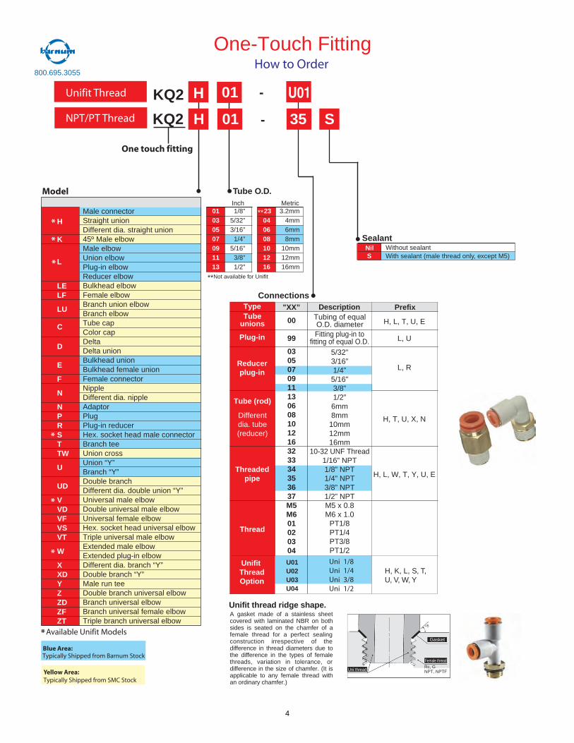
Prefix
KQ2 H 01 - 35 S
Type "XX” Description PrefixTube
unions 00
99
0305070911130608101216323334353637M5M601020304
Tubing of equalO.D. diameter H, L, T, U, E
L, U
L, R
H, T, U, X, N
H, L, W, T, Y, U, E
Plug-in Fitting plug-in tofitting of equal O.D.
5/32”3/16”1/4”5/16”3/8”1/2”6mm8mm
10mm12mm16mm
10-32 UNF Thread1/16” NPT1/8” NPT1/4” NPT3/8” NPT1/2” NPTM5 x 0.8M6 x 1.0
PT1/8PT1/4PT3/8PT1/2
Reducerplug-in
Tube (rod)
Differentdia. tube(reducer)
Threadedpipe
Thread
H
K
L
LELF
LU
C
D
E
F
N
NPRSTTW
U
UD
VVDVFVSVT
W
XXDYZZDZFZT
Tube O.D.
23040608101216
3.2mm4mm6mm8mm
10mm12mm16mm
01030507091113
1/8”5/32”3/16”1/4”
5/16”3/8”1/2”
Inch Metric
Connections
NilS
SealantWithout sealantWith sealant (male thread only, except M5)
DescriptionMale connectorStraight union
45º Male elbowMale elbowUnion elbowPlug-in elbowReducer elbowBulkhead elbowFemale elbowBranch union elbowBranch elbowTube capColor capDeltaDelta unionBulkhead unionBulkhead female unionFemale connectorNippleDifferent dia. nippleAdaptorPlugPlug-in reducer
Branch teeUnion crossUnion “Y”Branch “Y”Double branch
Universal male elbow
Universal female elbow
Extended male elbowExtended plug-in elbowDifferent dia. branch “Y”Double branch “Y”Male run tee
Branch universal elbow
Different dia. straight union
Hex. socket head male connector
Different dia. double union “Y”
Double universal male elbow
Hex. socket head universal elbowTriple universal male elbow
Double branch universal elbow
Branch universal female elbowTriple branch universal elbow 8
One-Touch Fitting
KQ2 H 01 -
U01U02U03U04
U01
One touch fitting
Unifit thread ridge shape.A gasket made of a stainless sheetcovered with laminated NBR on bothsides is seated on the chamfer of afemale thread for a perfect sealingconstruction irrespective of thedifference in thread diameters due tothe difference in the types of femalethreads, variation in tolerance, ordifference in the size of chamfer. (It isapplicable to any female thread withan ordinary chamfer.)
Rc, GNPT, NPTF
Gasket
Female thread
Uni thread
*
*
*
*
*
*
*Available Unifit Models
Unifit Thread
UnifitThreadOption
1/81/43/81/2
UniUniUniUni
H, K, L, S, T,U, V, W, Y
NPT/PT Thread
**
**Not available for Unifit
Model
How to Order
Blue Area:Typically Shipped from Barnum Stock
Yellow Area:Typically Shipped from SMC Stock
800.695.3055
4
� When more than onespecification is required,indicate in ascendingnumerical thenalphabetical order.
Note 1) Without a valvefunction.
Note 2) For threadtypes M5 and NPT.
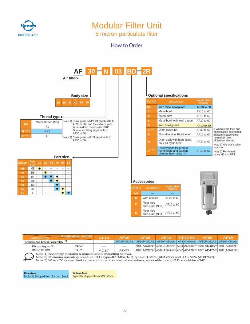
30 2RBDAF
Optional specifications
Accessories
Port size
Body size
Thread type
Air filter
Symbol
Nil
B
C
D
Nil
N Note 1)
F Note 2)
Description
—
With bracket
Float typeauto drain (N.C.)
Float typeauto drain (N.O.)
Metal bowl
Nylon bowl
Metal bowl with level gauge
With bowl guard
Drain guide 1/4
Flow direction: Right to left
Drain cock with barb fitting:ø6 x ø4 nylon tube
Display units for productname plate and cautionplate for bowl : PSI, °F
AF10 to 60
AF10 to 60
AF30 to 60
AF30 to 60
AF10 to 60
AF30 to 60
AF10 to 60
Metric thread (M5)
Rc
NPT
G
Nil
2
6
8
C
J
R
W
Z
Description ApplicablemodelsSymbol
Applicablemodels
—
AF20 to 60
AF10 to 60
AF30 to 60
Note 1)
Note 2)
Note 1) Drain guide is NPT1/4 (applicable toAF30 to 60), and the exhaust portfor auto drain comes with ø3/8"One-touch fitting (applicable toAF30 to 60).
Note 2) Drain guide is G1/4 (applicable toAF30 to 60).
03N
M5010203040610
M51/81/43/81/23/41
––––––
–
––––
––
–
Symbol Portsize 10 20 30 40 50 60
––
–––
–––––
––––––
10 20 30 40 50 60
Modular Filter Unit
How to Order
With metal bowl guard AF30 to 60
AF10 to 20
Applicable modelAccessory(1)
Float type (2)
auto-drainN.O.
N.C.
AF10—
—
AD17
AF20AF20P-050AS
—
AD27
AF30AF30P-050AS
AF40AF40P-050AS
AF40-06AF40P-070AS
AF50AF50P-050AS
AF60AF50P-050AS
Note 1) Assembly includes a bracket and 2 mounting screws.Note 2) Minimum operating pressure: N.O. type–0.1 MPa; N.C. type–0.1 MPa (AD17/27) and 0.15 MPa (AD37/47).Note 3) When “N” is specified in the end of part number of auto-drain, applicable tubing O.D should be ø3/8".
AD38 AD38N(3)
AD37 AD37N(3)
AD48 AD48N(3)
AD47 AD47N(3)
AD48 AD48N(3)
AD47 AD47N(3)
AD48 AD48N(3)
AD47 AD47N(3)
AD48 AD48N(3)
AD47 AD47N(3)
5 micron particulate fliter
Stand alone bracket assembly
Blue Area:Typically Shipped from Barnum Stock
Yellow Area:Typically Shipped from SMC Stock
800.695.3055
5
N.O.N.C.
Float type auto-drain
Accessory Part No.
AFM20
AF20P-050AS—
AD27
AFM30
AF30P-050AS
AFM40
AF40P-050AS
AFM40-06
AF40P-070AS
AccessoryApplicable model
(1)
Note 1) Assembly includes a bracket and 2 mounting screws.Note 2) Minimum operating pressure: N.O. type-0.1 MPa; N.C. type-0.1 MPa (AD17/27) and 0.15 MPa (AD37/47)..Note 3) When “N” is specified in the end of part number of auto-drain, applicable tubing O.D should be ø3/8".
(2) AD38AD37
AD38N(3)
AD37N(3)
AD48AD47
AD48N(3)
AD47N(3)
AD48AD47
AD48N(3)
AD47N(3)
Stand alone bracket assembly
Blue Area:Typically Shipped from Barnum Stock
Yellow Area:Typically Shipped from SMC Stock
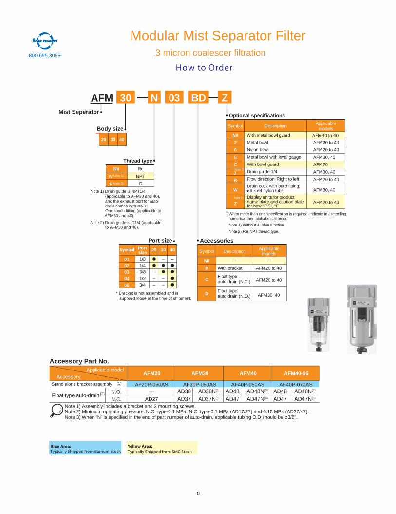
How to Order
Modular Mist Separator Filter.3 micron coalescer filtration
03 BDN30 ZAFM
Optional specifications
Port size
Mist Seperator
Thread type
Nil
N Note 1)
F Note 2)
Rc
NPT
G
Body size
Accessories
Symbol
Nil
B
C
D
Applicablemodels
—
AFM20 to 40
AFM20 to 40
AFM30, 40
Description
—
With bracket
Float typeauto drain (N.C.)
Float typeauto drain (N.O.)
Note 1) Drain guide is NPT1/4(applicable to AFM30 and 40),and the exhaust port for autodrain comes with ø3/8"One-touch fitting (applicable toAFM30 and 40).
Note 2) Drain guide is G1/4 (applicableto AFM30 and 40).
Metal bowl
Nylon bowl
Metal bowl with level gauge
With bowl guard
Drain guide 1/4
Flow direction: Right to left
Drain cock with barb fitting:ø6 x ø4 nylon tubeDisplay units for productname plate and caution platefor bowl: PSI, °F
AFM20 to 40
AFM20 to 40
AFM30, 40
AFM20
AFM30, 40
AFM20 to 40
AFM30, 40
AFM20 to 40
Symbol
Nil
2
6
8
C
J
R
W
Z
Description Applicablemodels
When more than one specification is required, indicate in ascendingnumerical then alphabetical order.
Note 1) Without a valve function.
Note 2) For NPT thread type.
Note 1)
Note 2)
20 30 40
0102030406
1/81/43/81/23/4
–––
–
––
–
Symbol Portsize 20 30 40
With metal bowl guard AFM30to 40
* Bracket is not assembled and is supplied loose at the time of shipment.
800.695.3055
6
N.O.N.C.
Float type auto-drain
Accessory Part No.
AFD20
AF20P-050AS—
AD27
AFD30
AF30P-050AS
AFD40
AF40P-050AS
AFD40-06
AF40P-070AS
AccessoryApplicable model
(1)
Note 1) Assembly includes a bracket and 2 mounting screws.Note 2) Minimum operating pressure: N.O. type-0.1 MPa; N.C. type-0.1 MPa (AD17/27) and 0.15 MPa (AD37/47)..Note 3) When “N” is specified in the end of part number of auto-drain, applicable tubing O.D should be ø3/8".
(2) AD38AD37
AD38N(3)
AD37N(3)
AD48AD47
AD48N(3)
AD47N(3)
AD48AD47
AD48N(3)
AD47N(3)
Stand alone bracket assembly
Blue Area:Typically Shipped from Barnum Stock
Yellow Area:Typically Shipped from SMC Stock
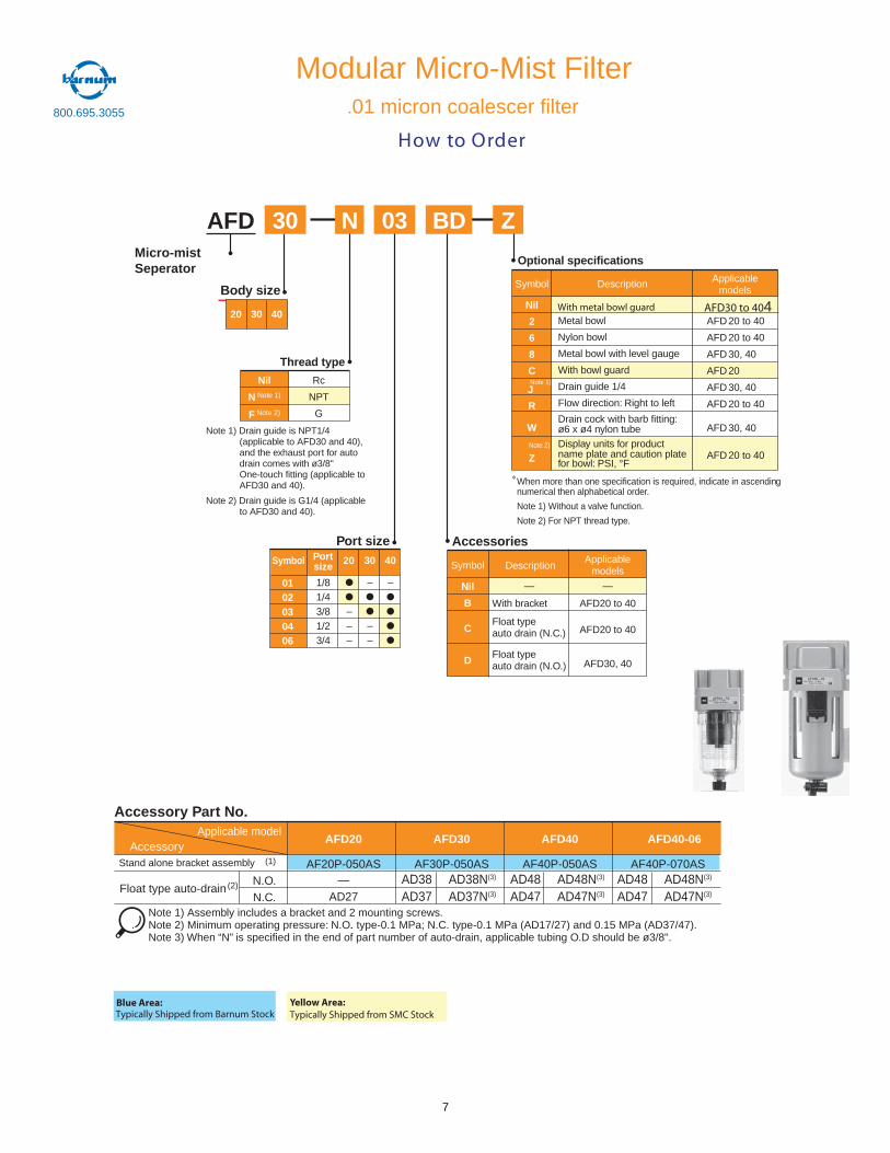
How to Order
Modular Micro-Mist Filter.01 micron coalescer filter
03 BDN30 ZAFD
Optional specifications
Port size
Micro-mistSeperator
Thread type
Nil
N Note 1)
F Note 2)
Rc
NPT
G
Body size
Accessories
Symbol
Nil
B
C
D
Applicablemodels
—
AFD20 to 40
AFD20 to 40
AFD30, 40
Description
—
With bracket
Float typeauto drain (N.C.)
Float typeauto drain (N.O.)
Note 1) Drain guide is NPT1/4(applicable to AFD30 and 40),and the exhaust port for autodrain comes with ø3/8"One-touch fitting (applicable toAFD30 and 40).
Note 2) Drain guide is G1/4 (applicableto AFD30 and 40).
Metal bowl
Nylon bowl
Metal bowl with level gauge
With bowl guard
Drain guide 1/4
Flow direction: Right to left
Drain cock with barb fitting:ø6 x ø4 nylon tubeDisplay units for productname plate and caution platefor bowl: PSI, °F
AFD20 to 40
AFD20 to 40
AFD30, 40
AFD20
AFD30, 40
AFD20 to 40
AFD30, 40
AFD20 to 40
Symbol
Nil
2
6
8
C
J
R
W
Z
Description Applicablemodels
When more than one specification is required, indicate in ascendingnumerical then alphabetical order.
Note 1) Without a valve function.
Note 2) For NPT thread type.
Note 1)
Note 2)
20 30 40
0102030406
1/81/43/81/23/4
–––
–
––
–
Symbol Portsize 20 30 40
With metal bowl guard AFD30 to 404
800.695.3055
7
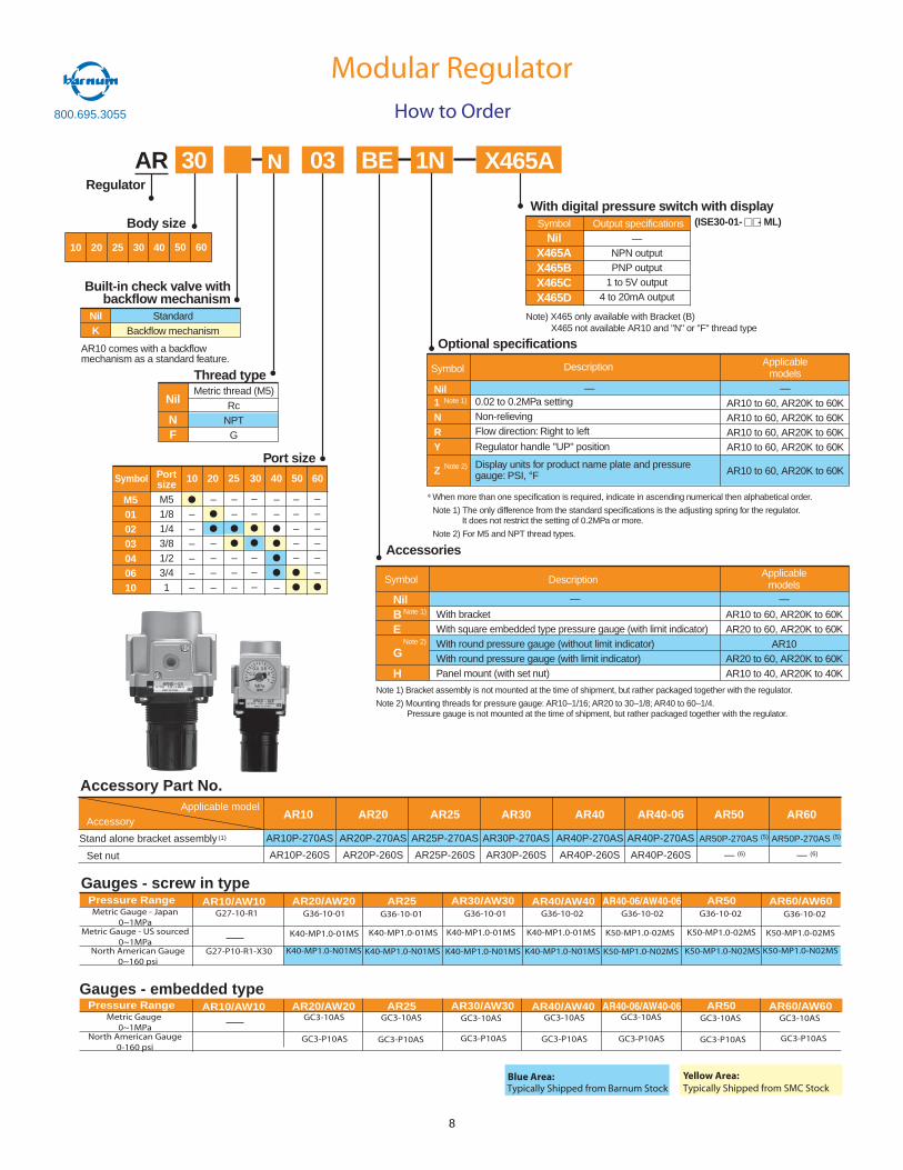
When more than one specification is required, indicate in ascending numerical then alphabetical order.
Note 1) The only difference from the standard specifications is the adjusting spring for the regulator.It does not restrict the setting of 0.2MPa or more.
Note 2) For M5 and NPT thread types.
Note 1) Bracket assembly is not mounted at the time of shipment, but rather packaged together with the regulator.
Note 2) Mounting threads for pressure gauge: AR10–1/16; AR20 to 30–1/8; AR40 to 60–1/4.Pressure gauge is not mounted at the time of shipment, but rather packaged together with the regulator.
Body size
AR 30 BE 1N03Regulator
Thread type
Port size
Accessories
Optional specifications
Symbol
NilBE
G
H
Applicablemodels
—
AR10 to 60, AR20K to 60KAR20 to 60, AR20K to 60K
AR10AR20 to 60, AR20K to 60KAR10 to 40, AR20K to 40K
Description
—
With bracketWith square embedded type pressure gauge (with limit indicator)With round pressure gauge (without limit indicator)With round pressure gauge (with limit indicator)Panel mount (with set nut)
Nil
NF
Metric thread (M5)Rc
NPTG
Symbol
Nil1NRY
Z
Description
0.02 to 0.2MPa settingNon-relievingFlow direction: Right to left
Regulator handle "UP" position
Display units for product name plate and pressuregauge: PSI, °F
Applicablemodels
AR10 to 60, AR20K to 60KAR10 to 60, AR20K to 60KAR10 to 60, AR20K to 60KAR10 to 60, AR20K to 60K
AR10 to 60, AR20K to 60K
Note 1)
Note 2)
Note 1)
Note 2)
Built-in check valve withbackflow mechanism
AR10 comes with a backflowmechanism as a standard feature.
With digital pressure switch with display
NilK
StandardBackflow mechanism
SymbolNil
X465AX465BX465CX465D
Output specifications
NPN outputPNP output
1 to 5V output4 to 20mA output
(ISE30-01- - ML)
— —
X465A
—
Note) X465 only available with Bracket (B)X465 not available AR10 and "N" or "F" thread type
10 20 30 40 50 6025
M5010203040610
M51/81/43/81/23/41
––––––
–
––––
––
–––
––
–
Symbol Portsize 10 20 30 40 50 6025
––
–––
–––––
––––––
11
Modular RegulatorHow to Order
N
Applicable modelAccessory
(1)
Set nut
AR10
AR10P-270AS
AR10P-260S
AR20
AR20P-270AS
AR20P-260S
AR25
AR25P-270AS
AR25P-260S
AR30
AR30P-270AS
AR30P-260S
AR40
AR40P-270AS
AR40P-260S
AR40-06
AR40P-270AS
AR40P-260S
AR50
AR50P-270AS (5)
— (6)
AR60
AR50P-270AS (5)
— (6)
Accessory Part No.
Gauges - screw in typePressure Range AR10/AW10 AR20/AW20 AR25 AR30/AW30 AR40/AW40 AR40-06/AW40-06 AR50 AR60/AW60
G27-10-R1 G36-10-01 G36-10-01 G36-10-01 G36-10-02 G36-10-02 G36-10-02 G36-10-02
K40-MP1.0-01MS K40-MP1.0-01MS K40-MP1.0-01MS K50-MP1.0-02MSK40-MP1.0-01MS K50-MP1.0-02MS K50-MP1.0-02MS
Metric Gauge - Japan0~1MPa
Metric Gauge - US sourced0~1MPa
G27-P10-R1-X30 K40-MP1.0-N01MS K40-MP1.0-N01MS K40-MP1.0-N01MS K40-MP1.0-N01MS K50-MP1.0-N02MS K50-MP1.0-N02MS K50-MP1.0-N02MS
Pressure Range AR10/AW10 AR20/AW20 AR25 AR30/AW30 AR40/AW40 AR40-06/AW40-06 AR50 AR60/AW60GC3-10AS GC3-10ASMetric Gauge
0~1MPaNorth American Gauge
0-160 psi
Gauges - embedded type
GC3-10AS GC3-10AS GC3-10AS GC3-10AS GC3-10AS
GC3-P10AS GC3-P10AS GC3-P10AS GC3-P10AS GC3-P10AS GC3-P10AS GC3-P10AS
North American Gauge0~160 psi
Stand alone bracket assembly
Blue Area:Typically Shipped from Barnum Stock
Yellow Area:Typically Shipped from SMC Stock
800.695.3055
8
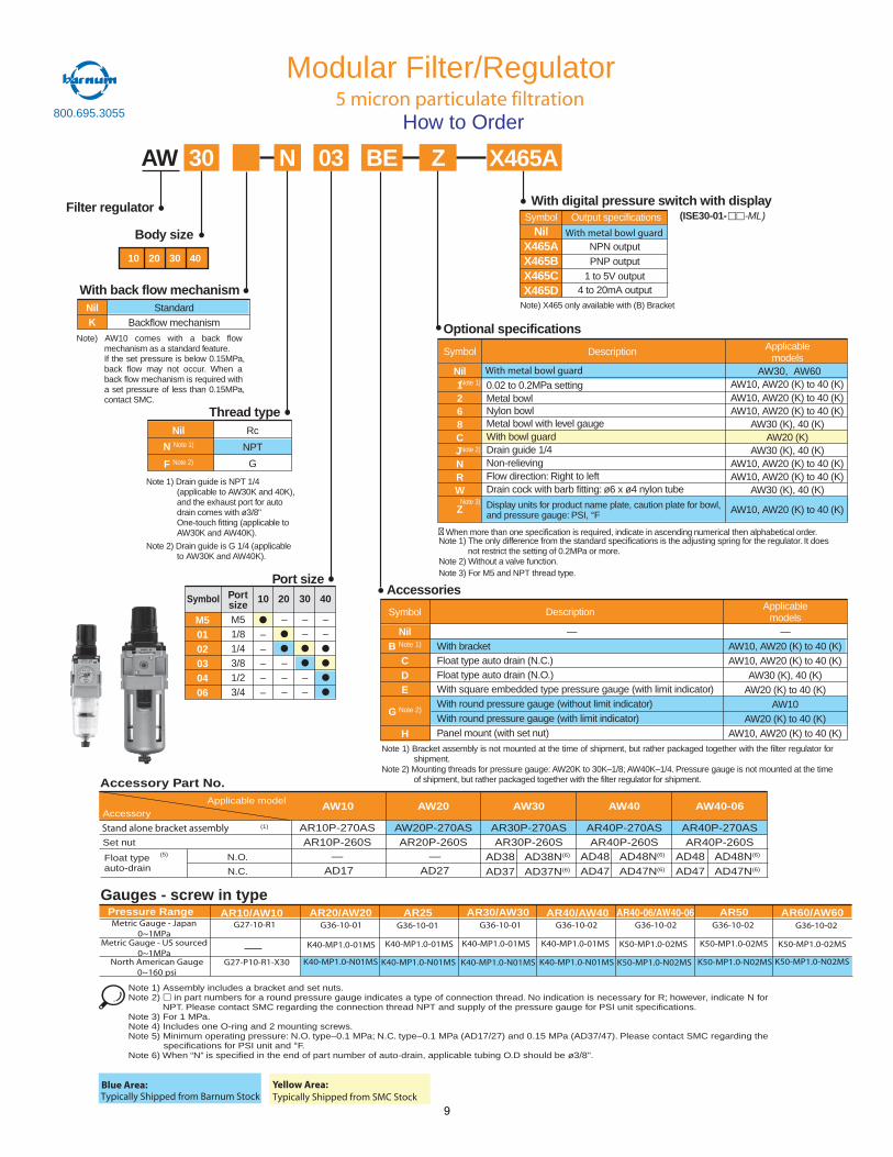
Body size
With back flow mechanism
Filter regulator
Accessories
Optional specifications
ZAW 30 03 BEN
Description
0.02 to 0.2MPa settingMetal bowlNylon bowlMetal bowl with level gaugeWith bowl guardDrain guide 1/4Non-relievingFlow direction: Right to leftDrain cock with barb fitting: ø6 x ø4 nylon tube
Display units for product name plate, caution plate for bowl,and pressure gauge: PSI, °F
Symbol
NilB Note 1)
CDE
G Note 2)
H
Description
—With bracketFloat type auto drain (N.C.)Float type auto drain (N.O.)With square embedded type pressure gauge (with limit indicator)With round pressure gauge (without limit indicator)With round pressure gauge (with limit indicator)Panel mount (with set nut)
Applicablemodels
—AW10, AW20 (K) to 40 (K)AW10, AW20 (K) to 40 (K)
AW30 (K), 40 (K)AW20 (K) to 40 (K)
AW10AW20 (K) to 40 (K)
AW10, AW20 (K) to 40 (K)
Symbol
Nil1268CJNRW
Z
Applicablemodels
AW10, AW20 (K) to 40 (K)AW10, AW20 (K) to 40 (K)AW10, AW20 (K) to 40 (K)
AW30 (K), 40 (K)AW20 (K)
AW30 (K), 40 (K)AW10, AW20 (K) to 40 (K)AW10, AW20 (K) to 40 (K)
AW30 (K), 40 (K)
AW10, AW20 (K) to 40 (K)
Thread typeNil
N Note 1)
F Note 2)
Rc
NPT
G
Port size
Note 1) Drain guide is NPT 1/4(applicable to AW30K and 40K),and the exhaust port for autodrain comes with ø3/8"One-touch fitting (applicable toAW30K and AW40K).
Note 2) Drain guide is G 1/4 (applicableto AW30K and AW40K).
Note 1) Bracket assembly is not mounted at the time of shipment, but rather packaged together with the filter regulator forshipment.
Note 2) Mounting threads for pressure gauge: AW20K to 30K–1/8; AW40K–1/4. Pressure gauge is not mounted at the timeof shipment, but rather packaged together with the filter regulator for shipment.
� When more than one specification is required, indicate in ascending numerical then alphabetical order.Note 1) The only difference from the standard specifications is the adjusting spring for the regulator. It does
not restrict the setting of 0.2MPa or more.Note 2) Without a valve function.Note 3) For M5 and NPT thread type.
Note) AW10 comes with a back flowmechanism as a standard feature.If the set pressure is below 0.15MPa,back flow may not occur. When aback flow mechanism is required witha set pressure of less than 0.15MPa,contact SMC.
Note 1)
Note 2)
Note 3)
NilK
StandardBackflow mechanism
With digital pressure switch with displaySymbol
NilX465AX465BX465CX465D
Output specifications
NPN outputPNP output
1 to 5V output4 to 20mA output
(ISE30-01- -ML)
X465A
Note) X465 only available with (B) Bracket
10 20 30 40
Modular Filter/Regulator
With metal bowl guard
How to Order
With metal bowl guard AW30, AW60
M50102030406
M51/81/43/81/23/4
–––––
–
–––
––
––
––
Symbol Portsize 10 20 30 40
Accessory(1)
Set nut
Float typeauto-drain
Applicable model AW40-06AW40AW30AW20AW10
AR10P-270ASAR10P-260S
—AD17
N.O.
N.C.
AW20P-270ASAR20P-260S
—AD27
AR30P-270ASAR30P-260S
AR40P-270ASAR40P-260S
AR40P-270ASAR40P-260S
Accessory Part No.
Note 1) Assembly includes a bracket and set nuts.Note 2) in part numbers for a round pressure gauge indicates a type of connection thread. No indication is necessary for R; however, indicate N for
NPT. Please contact SMC regarding the connection thread NPT and supply of the pressure gauge for PSI unit specifications.Note 3) For 1 MPa.Note 4) Includes one O-ring and 2 mounting screws.Note 5) Minimum operating pressure: N.O. type–0.1 MPa; N.C. type–0.1 MPa (AD17/27) and 0.15 MPa (AD37/47). Please contact SMC regarding the
specifications for PSI unit and °F.Note 6) When “N” is specified in the end of part number of auto-drain, applicable tubing O.D should be ø3/8".
(5) AD38 AD38N(6)
AD37 AD37N(6)
AD48 AD48N(6)
AD47 AD47N(6)
AD48 AD48N(6)
AD47 AD47N(6)
Gauges - screw in typePressure Range AR10/AW10 AR20/AW20 AR25 AR30/AW30 AR40/AW40 AR40-06/AW40-06 AR50 AR60/AW60
G27-10-R1 G36-10-01 G36-10-01 G36-10-01 G36-10-02 G36-10-02 G36-10-02 G36-10-02
K40-MP1.0-01MS K40-MP1.0-01MS K40-MP1.0-01MS K50-MP1.0-02MSK40-MP1.0-01MS K50-MP1.0-02MS K50-MP1.0-02MS
Metric Gauge - Japan0~1MPa
Metric Gauge - US sourced0~1MPa
G27-P10-R1-X30 K40-MP1.0-N01MS K40-MP1.0-N01MS K40-MP1.0-N01MS K40-MP1.0-N01MS K50-MP1.0-N02MS K50-MP1.0-N02MS K50-MP1.0-N02MSNorth American Gauge0~160 psi
5 micron particulate filtration
Stand alone bracket assembly
Blue Area:Typically Shipped from Barnum Stock
Yellow Area:Typically Shipped from SMC Stock
800.695.3055
9
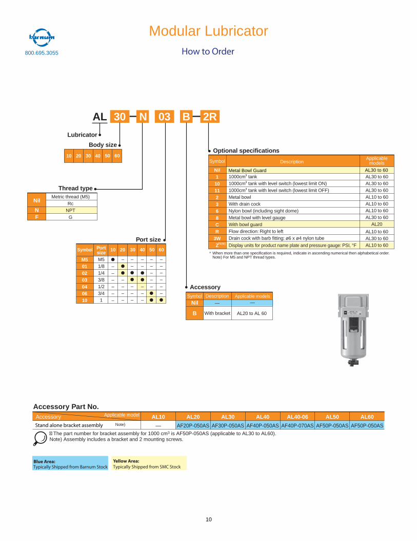
Thread type
AL 2R30 03 BN
Lubricator
Body sizeOptional specifications
AccessorySymbol
Nil
B
Description—
Applicable models—
With bracket AL20 to AL 60
Description
1000cm tank1000cm tank with level switch (lowest limit ON)1000cm tank with level switch (lowest limit OFF)Metal bowlWith drain cockNylon bowl (including sight dome)Metal bowl with level gaugeWith bowl guardFlow direction: Right to leftDrain cock with barb fitting: ø6 x ø4 nylon tube
Display units for product name plate and pressure gauge: PSI, °F
Symbol
Nil110112368CR
3WZ
Applicablemodels
AL30 to 60AL30 to 60AL30 to 60AL10 to 60AL10 to 60AL10 to 60AL30 to 60
AL20
AL10 to 60AL30 to 60AL10 to 60
When more than one specification is required, indicate in ascending numerical then alphabetical order.Note) For M5 and NPT thread types.
Note)
Nil
NF
Metric thread (M5)Rc
NPTG
10 20 30 40 50 60
Port size
M5010203040610
M51/81/43/81/23/41
––––––
–
––––
––
–––
Symbol Portsize 10 20 30 40 50 60
––
–––
–––––
––––––
Modular Lubricator
Metal Bowl Guard AL30 to 60
AL10
—
AL20
AF20P-050AS
AL30
AF30P-050AS
AL40
AF40P-050AS
AL40-06
AF40P-070AS
AL50
AF50P-050AS
AL60
AF50P-050AS
Accessory Part No.Applicable modelAccessory
Note)
� The part number for bracket assembly for 1000 cm3 is AF50P-050AS (applicable to AL30 to AL60).Note) Assembly includes a bracket and 2 mounting screws.
Stand alone bracket assembly
How to Order
Blue Area:Typically Shipped from Barnum Stock
Yellow Area:Typically Shipped from SMC Stock
800.695.3055
10
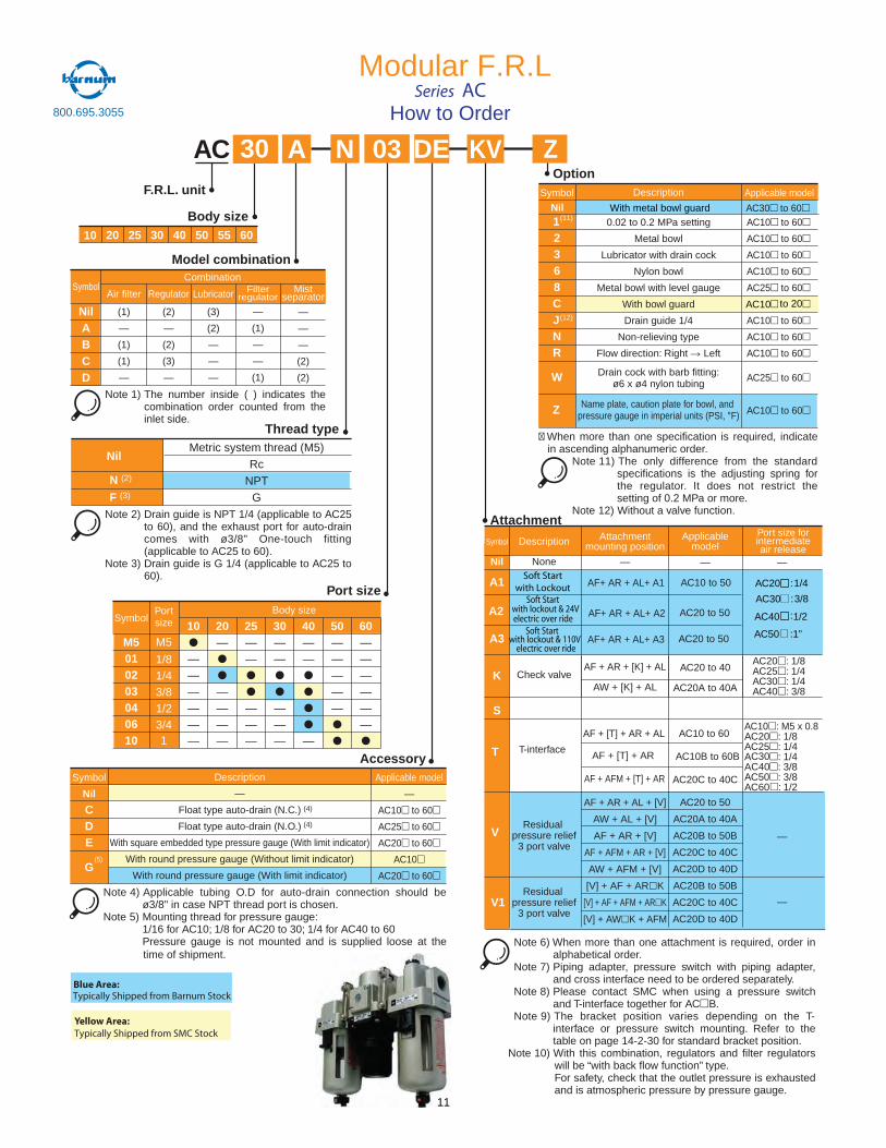
AC A N 03 KV
Body size
Model combination
F.R.L. unit
SymbolAir filter
(1)
—
(1)
(1)
—
Regulator
(2)
—
(2)
(3)
—
Lubricator
(3)
(2)
—
—
—
Filterregulator
—
(1)
—
—
(1)
Mistseparator
—
—
—
(2)
(2)
Combination
Thread type
Nil
N (2)
F (3)
Metric system thread (M5)Rc
NPTG
Port size
AccessoryApplicable model
—
AC10 to 60
AC25 to 60
AC20 to 60
AC10
AC20 to 60
Symbol
Nil
CDE
G
Description
—
Float type auto-drain (N.C.)
Float type auto-drain (N.O.)
With square embedded type pressure gauge (With limit indicator)
With round pressure gauge (Without limit indicator)
With round pressure gauge (With limit indicator)
Option
0.02 to 0.2 MPa setting
Metal bowl
Lubricator with drain cock
Nylon bowl
Metal bowl with level gauge
With bowl guard
Drain guide 1/4
Non-relieving type
Flow direction: Right Left
Drain cock with barb fitting:ø6 x ø4 nylon tubing
Name plate, caution plate for bowl, and pressure gauge in imperial units (PSI, °F)
AC10 to 60
AC10 to 60
AC10 to 60
AC10 to 60
AC25 to 60
AC10 to 60
AC10 to 60
AC10 to 60
AC25 to 60
AC10 to 60
12368CJNR
W
Z
Attachment
� When more than one specification is required, indicatein ascending alphanumeric order.
Note 11) The only difference from the standardspecifications is the adjusting spring forthe regulator. It does not restrict thesetting of 0.2 MPa or more.
Note 12) Without a valve function.
Note 6) When more than one attachment is required, order inalphabetical order.
Note 7) Piping adapter, pressure switch with piping adapter,and cross interface need to be ordered separately.
Note 8) Please contact SMC when using a pressure switchand T-interface together for AC B.
Note 9) The bracket position varies depending on the T-interface or pressure switch mounting. Refer to thetable on page 14-2-30 for standard bracket position.
Note 10) With this combination, regulators and filter regulatorswill be “with back flow function” type.For safety, check that the outlet pressure is exhaustedand is atmospheric pressure by pressure gauge.
Note 1) The number inside ( ) indicates thecombination order counted from theinlet side.
Note 2) Drain guide is NPT 1/4 (applicable to AC25to 60), and the exhaust port for auto-draincomes with ø3/8" One-touch fitting(applicable to AC25 to 60).
Note 3) Drain guide is G 1/4 (applicable to AC25 to60).
Note 4) Applicable tubing O.D for auto-drain connection should beø3/8" in case NPT thread port is chosen.
Note 5) Mounting thread for pressure gauge:1/16 for AC10; 1/8 for AC20 to 30; 1/4 for AC40 to 60Pressure gauge is not mounted and is supplied loose at thetime of shipment.
Symbol Description Applicable model
(5)
(11)
(12)
Symbol Description Applicablemodel
Attachmentmounting position
Port size forintermediateair release
02 52 03 04 05 55 0610
SymbolPortsize
M5
1/81/43/81/23/41
10
——————
20—
————
25——
———
30——
———
40——
—
50—————
60——————
Body size
(4)
(4)
Nil
K
S
T
V
V1
None
Check valve
T-interface
—
AC20 to 40
AC20A to 40A
AC10 to 60
AC10B to 60B
AC20C to 40C
AC20 to 50
AC20A to 40A
AC20B to 50B
AC20C to 40C
AC20D to 40D
AC20B to 50B
AC20C to 40C
AC20D to 40D
—
AF + AR + [K] + AL
AW + [K] + AL
AF + [T] + AR + AL
AF + [T] + AR
AF + AFM + [T] + AR
AF + AR + AL + [V]
AW + AL + [V]
AF + AR + [V]
AF + AFM + AR + [V]
AW + AFM + [V]
[V] + AF + AR K
[V] + AF + AFM + AR K
[V] + AW K + AFM
AC20 : 1/8AC25 : 1/4AC30 : 1/4AC40 : 3/8
AC10 : M5 x 0.8AC20 : 1/8AC25 : 1/4AC30 : 1/4AC40 : 3/8AC50 : 3/8AC60 1/2
—
—
—Residual
pressure relief3 port valve
Residualpressure relief
3 port valve
M5010203040610
NilABCD
30 DE Z
Modular F.R.L
A1
A2
How to OrderSeries AC
Soft Startwith Lockout
with lockout & 24V Soft Start
electric over rideSoft Start
with lockout & 110V electric over ride
A3
AF+ AR + AL+ A1
AF+ AR + AL+ A2
AF+ AR + AL+ A3
AC10 to 20
AC20 : 1/4
AC30 : 3/8
Nil With metal bowl guard AC30 to 60
AC10 to 50
AC20 to 50
AC20 to 50
AC40 1/2
AC50 : ”1
:
Blue Area:Typically Shipped from Barnum Stock
Yellow Area:Typically Shipped from SMC Stock
:
800.695.3055
11
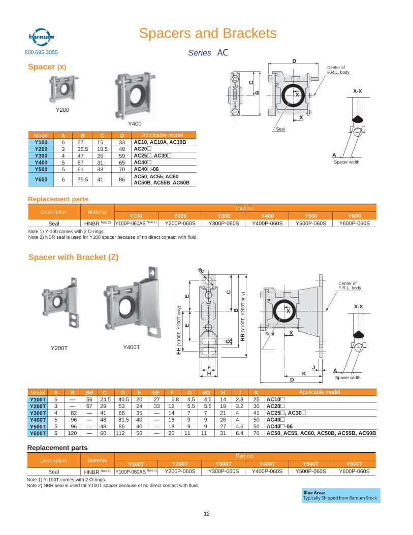
Spacer (X)
Description
Seal
Material
HNBR Note 2)
Y100Y100P-060AS Note 1)
Y200Y200P-060S
Y300Y300P-060S
Y400Y400P-060S
Y500Y500P-060S
Y600Y600P-060S
Part no.
Replacement parts
Spacer with Bracket (Z)
Y400T
BC
D
Seal
Center of F.R.L. body
X
ModelY100Y200Y300Y400Y500
Y600
AC10, AC10A, AC10BAC20AC25 , AC30AC40AC40 -06AC50, AC55, AC60AC50B, AC55B, AC60B
A63455
6
B2735.5475761
75.5
C1518.5263133
41
D3348596570
86
Applicable model
AC10AC20AC25 , AC30AC40AC40 -06AC50, AC55, AC60, AC50B, AC55B, AC60B
A634556
B——
82 96 96120
BB5667————
C24.52941484860
D40.5536881.586
112
E202435404050
EE2733————
G 4.5 5.5 7 9 911
øG 4.5 5.5 7 9 911
ModelY100TY200TY300TY400TY500TY600T
F 6.81214181820
J2.83.2444.66.4
K253041505070
H141921262731
Applicable model
JK
D
BB
(Y10
0T, Y
200T
onl
y)
BC
H
E
øG
EE
(Y10
0T, Y
200T
onl
y)
E
G
F
Center ofF.R.L. body
X
Description
Seal
Material
HNBR Note 2)
Y100TY100P-060AS Note 1)
Y200TY200P-060S
Y300TY300P-060S
Y400TY400P-060S
Y500TY500P-060S
Y600TY600P-060S
Part no.
Replacement parts
Seal
Y200T
Y200
REL
EASE
1
2
REL
EASE
1
2
Note 1) Y-100 comes with 2 O-rings.Note 2) NBR seal is used for Y100 spacer because of no direct contact with fluid.
Note 1) Y-100T comes with 2 O-rings.Note 2) NBR seal is used for Y100T spacer because of no direct contact with fluid.
Y400
ASpacer width
X-X
ASpacer width
X-X
X
X
Spacers and BracketsSeries AC
Blue Area:Typically Shipped from Barnum Stock
800.695.3055
12
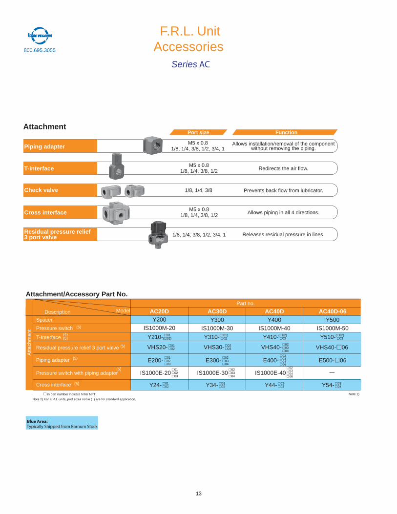
F.R.L. Unit
Attachment
Piping adapter
Check valve
T-interface
Cross interface
Residual pressure relief 3 port valve
Port size
Allows installation/removal of the componentwithout removing the piping.
Redirects the air flow.
Prevents back flow from lubricator.
Allows piping in all 4 directions.
Releases residual pressure in lines.
Function
M5 x 0.81/8, 1/4, 3/8, 1/2, 3/4, 1
M5 x 0.81/8, 1/4, 3/8, 1/2
M5 x 0.81/8, 1/4, 3/8, 1/2
1/8, 1/4, 3/8, 1/2, 3/4, 1
1/8, 1/4, 3/8
Attachment/Accessory Part No.
(5)
(5)
(5)
(5)
(4)(5)
Atta
chm
ent
ModelDescription
Piping adapter
Pressure switch with piping adapter
Cross interface
Residual pressure relief 3 port valve (5)
Spacer
Pressure switch
T-Interface
Part no.
AC20DY200
IS1000M-20
AC30DY300
IS1000M-30
AC40DY400
IS1000M-40
AC40D-06Y500
IS1000M-50
E200-010203
E300-020304
IS1000E-20010203
IS1000E-30020304
VHS20- 0102 VHS30- 02
03
Y24- 0102 Y34- 01
02
Y210- 01( 02) Y310-( 01)
02
E400-02030406
02030406
020304
IS1000E-40
VHS40-
Y44- 0203
Y410-( 02)03
E500- 06
VHS40- 06
—
Y54- 0304
Y510-( 02)03
Note 1) in part number indicate N for NPT.
Note 2) For F.R.L units, port sizes not in ( ) are for standard application.
AccessoriesSeries AC
Blue Area:Typically Shipped from Barnum Stock
800.695.3055
13
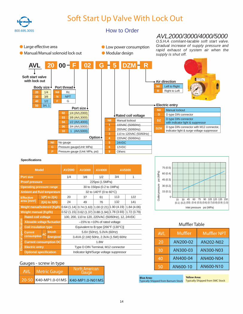
Body size
AVL
Port size
Manual lockout
100VAC (50/60Hz)
200VAC (50/60Hz)
110 to 120VAC (50/60Hz)
220VAC (50/60Hz)
24VDC
12VDC
Others
Nil
1
2
3
4
5
6
9
02
03
04
06
10
1/4
3/8
1/2
3/4, 1
02
20
30
40
50
G
1/4 (AVL2000)
3/8 (AVL3000)
1/2 (AVL4000)
3/4 (AVL5000)
1 (AVL5000)
Port threadRc
NPT
G
Soft start valvewith lock out
20 00 F DZM R5
Nil
N
F
Option
Rated coil voltage
Nil
G
P
No gauge
Pressure gauge(Unit: MPa)
Pressure gauge (Unit: MPa, psi)
Manual lockout
D type DIN connector
D type DIN connectorwith indicator light & suppressor
D type DIN connector with M12 connector,indicator light & surge voltage suppressor
Nil
D
DZ
DZM
Electric entry
Left to Right
Right to Left
Nil
R
Air direction
Port size
Proof pressure
Operating pressure range
Ambient and fluid temperature
Weight manual/solenoid (Kg/lb)
Weight manual (Kg/lb)
Specifications
Model
100, 200, 110 to 120, 220VAC (50/60Hz), 12, 24VDC
–15% to +10% of rated voltage
Equivalent to B type [266°F (130°C)]
5.6V (50Hz), 5.0VA (60Hz)
3.4VA (2.1W) 50Hz, 2.3VA (1.5W) 60Hz
1.8W
Type D DIN Terminal, M12 connector
Indicator light/Surge voltage suppressor
Rated coil voltage
Allowable voltage fluctuation
Coil insulation type
Current consumption DC
Electric entry
Optional specification
Ele
ctri
cals
peci
ficat
ion
AV2000
1/4
20
24
0.64 (1.14)
0.52 (1.15)
AV3000
3/8
37
49
0.74 (1.63)
0.62 (1.37)
AV4000
1/2
61
76
1.00 (2.21)
0.88 (1.94)
AV5000
3/4
113
132
1.90 (4.19)
1.78 (3.93)
1
122
141
1.84 (4.06)
1.72 (3.79)
225psi (1.5MPa)
30 to 150psi (0.2 to 1MPa)
32 to 140°F (0 to 60°C)
Soft Start Up Valve With Lock Out
Piston B Switching Pressure (Close to Open)
15(0.1)
30(0.2)
45(03)
60(0.4)
75(0.5)
90(0.6)
105(0.7)
120(0.8)
135(0.9)
150(1.0)
Inlet pressure psi (MPa)
Out
letp
ress
ure
psi(
MP
a)
0
15 (0.1)
30 (0.2)
45 (0.3)
60 (0.4)
75 (0.5)
Large e ective area Low power consumptionManual/Manual solenoid lock out Modular design
O.S.H.A comliant-lacable soft start valve.Gradual increase of supply pressure andrapid exhaust of system air when thesupply is shut off.
AVL2000/3000/4000/5000
1(P) to 2(A)
2(A) to 3(R)Effectivearea (mm2)
Inrush
EnergizedCurrentconsumption AC
00
How to Order
AVL Muffler Muffler NPT
20
30
40
50
AN200-02
AN300-03
AN400-04
AN600-10
Muffler Table
AN202-N02
AN300-N03
AN400-N04
AN600-N10
K40-MP1.0-N01MS
AVL
20-50
Gauges - screw in type
Metric GaugeNorth American
Gauge
K40-MP1.0-01MSBlue Area:Typically Shipped from Barnum Stock
Yellow Area:Typically Shipped from SMC Stock
800.695.3055
14
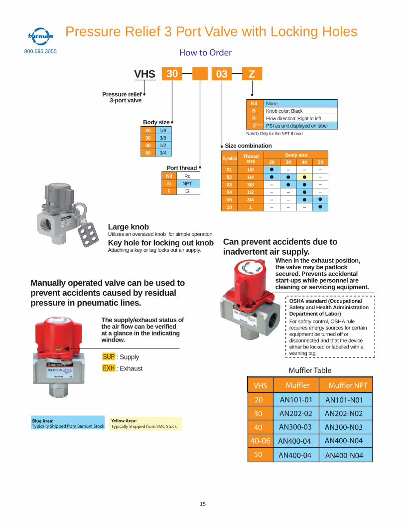
Body size
VHS
Size combination
None
Knob color: Black
Flow direction: Right to left
PSI as unit displayed on label
Nil
B
R
ZNote1)
–
–
–
–
01
02
03
04
06
10
1/8
3/8
1/2
3/4
03
20
30
40
50
Z
1/8
1/4
3/8
1/2
3/4
1
Port threadRc
NPT
G
Nil
N
F
20 30 40 50–
–
–
–
–
–
–
–
–
–
Symbol Threadsize
Body size
Note1) Only for the NPT thread
Pressure relief3-port valve
The supply/exhaust status ofthe air flow can be verifiedat a glance in the indicatingwindow.
: Supply
: Exhaust
When in the exhaust position,the valve may be padlocksecured. Prevents accidentalstart-ups while personnel arecleaning or servicing equipment.
OSHA standard (OccupationalSafety and Health AdministrationDepartment of Labor)For safety control, OSHA rulerequires energy sources for certainequipment be turned off ordisconnected and that the deviceeither be locked or labelled with awarning tag.SUP
EXH
Manually operated valve can be used toprevent accidents caused by residualpressure in pneumatic lines.
Can prevent accidents due toinadvertent air supply.
30
Large knobUtilizes an oversized knob for simple operation.
Key hole for locking out knobAttaching a key or tag locks out air supply.
Pressure Relief 3 Port Valve with Locking Holes
VHS Muffler Muffler NPT
20
30
40
50
AN101-01
AN202-02
AN300-03
AN400-04
Muffler Table
AN101-N01
AN202-N02
AN300-N03
AN400-N0440-06
AN400-04 AN400-N04
How to Order
Blue Area:Typically Shipped from Barnum Stock
Yellow Area:Typically Shipped from SMC Stock
800.695.3055
15
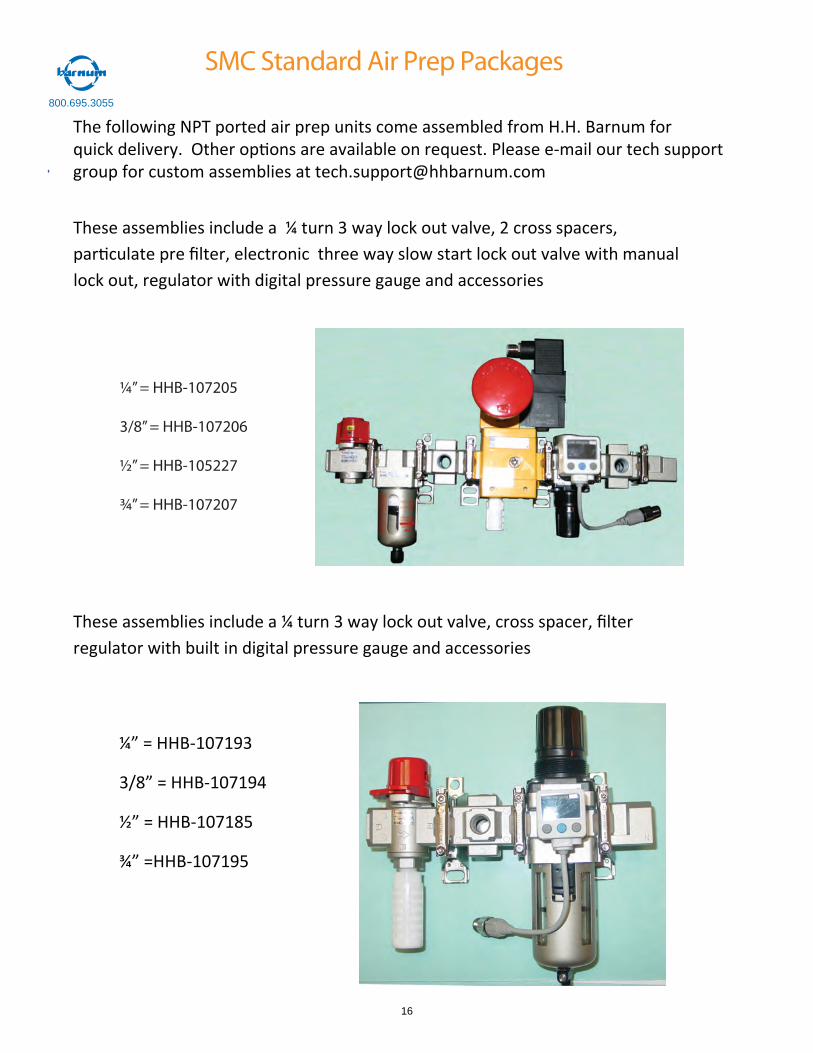
SMC Standard Air Prep Packages
The following NPT ported air prep units come assembled from H.H. Barnum forquick delivery. Other op ons are available on request. Please e-mail our tech supportgroup for custom assemblies at [email protected]
These assemblies include a ¼ turn 3 way lock out valve, 2 cross spacers, par culate pre filter, electronic three way slow start lock out valve with manual lock out, regulator with digital pressure gauge and accessories
¼” = HHB-107205
3/8” = HHB-107206
½” = HHB-105227
¾” = HHB-107207
These assemblies include a ¼ turn 3 way lock out valve, cross spacer, filter regulator with built in digital pressure gauge and accessories
¼” = HHB-107193
3/8” = HHB-107194
½” = HHB-107185
¾” =HHB-107195
800.695.3055
16
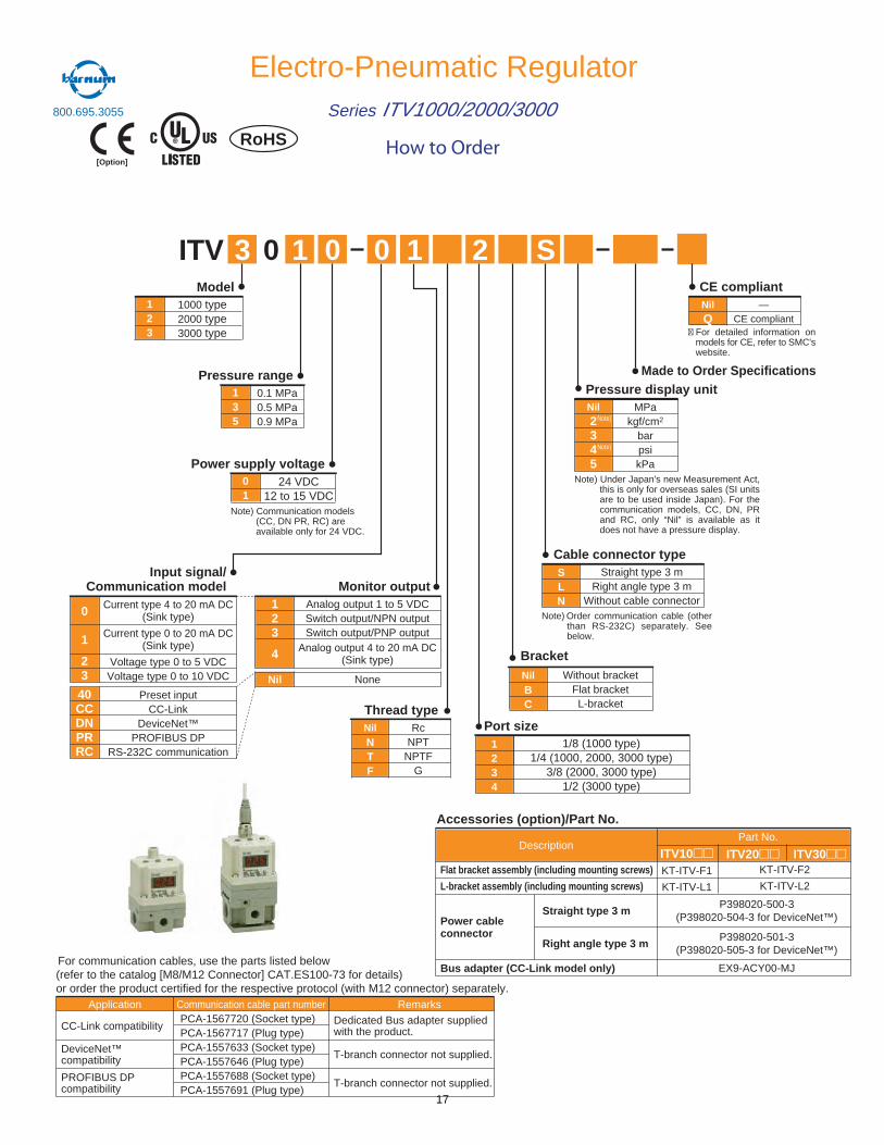
Electro-Pneumatic RegulatorSeries ITV1000/2000/3000
How to Order[Option]
RoHS
Input signal/Communication model
0
1
23
Voltage type 0 to 5 VDCVoltage type 0 to 10 VDC
Current type 4 to 20 mA DC(Sink type)
Current type 0 to 20 mA DC(Sink type)
40CCDNPRRC
Preset inputCC-Link
DeviceNet™PROFIBUS DP
RS-232C communication
Monitor output123
4
Analog output 1 to 5 VDCSwitch output/NPN outputSwitch output/PNP output
Analog output 4 to 20 mA DC(Sink type)
Nil None
ITV
Pressure range
3 0 1 0
135
0.1 MPa0.5 MPa0.9 MPa
S0 1 2
Nil2345
MPakgf/cm2
barpsikPa
Cable connector typeSLN
Straight type 3 mRight angle type 3 m
Without cable connector
BracketNilBC
Without bracketFlat bracketL-bracketThread type
NilNTF
RcNPT
NPTFG
Port size1234
1/8 (1000 type)1/4 (1000, 2000, 3000 type)
3/8 (2000, 3000 type)1/2 (3000 type)
Power supply voltage01
24 VDC12 to 15 VDC
Model123
1000 type2000 type3000 type
Note)
Note)
Note) Communication models (CC, DN PR, RC) are available only for 24 VDC.
Pressure display unitMade to Order Specifications
CE compliantNilQ
—CE compliant
� For detailed information on models for CE, refer to SMC'swebsite.
Note) Under Japan's new Measurement Act, this is only for overseas sales (SI units are to be used inside Japan). For the communication models, CC, DN, PR and RC, only “Nil” is available as it does not have a pressure display.
Note) Order communication cable (other than RS-232C) separately. See below.
Application
CC-Link compatibility
DeviceNet™compatibility
PROFIBUS DP compatibility
Communication cable part numberPCA-1567720 (Socket type)PCA-1567717 (Plug type)PCA-1557633 (Socket type)PCA-1557646 (Plug type)PCA-1557688 (Socket type)PCA-1557691 (Plug type)
Remarks
Dedicated Bus adapter supplied with the product.
T-branch connector not supplied.
T-branch connector not supplied.
For communication cables, use the parts listed below (refer to the catalog [M8/M12 Connector] CAT.ES100-73 for details) or order the product certified for the respective protocol (with M12 connector) separately.
ITV10 ITV20 ITV30
L-bracket assembly (including mounting screws)
Straight type 3 m
Right angle type 3 m
Power cable connector
Description
KT-ITV-F2
P398020-500-3(P398020-504-3 for DeviceNet™)
P398020-501-3(P398020-505-3 for DeviceNet™)
EX9-ACY00-MJ
Part No.
KT-ITV-F1KT-ITV-L2KT-ITV-L1
Flat bracket assembly (including mounting screws)
Bus adapter (CC-Link model only)
Accessories (option)/Part No.
800.695.3055
17
RoHS
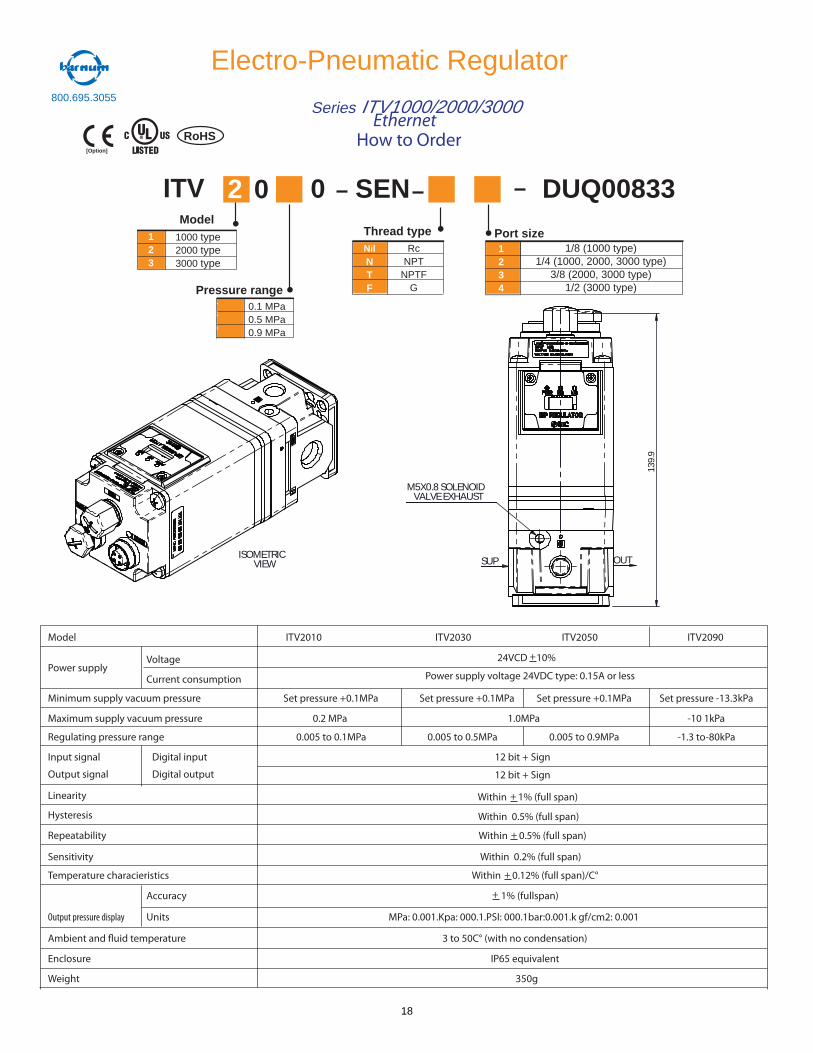
Electro-Pneumatic Regulator
Series ITV1000/2000/3000
How to Order[Option]
ITV
Pressure range
2 0
135
0.1 MPa0.5 MPa0.9 MPa
Thread typeNilNTF
RcNPT
NPTFG
Port size1234
1/8 (1000 type)1/4 (1000, 2000, 3000 type)
3/8 (2000, 3000 type)1/2 (3000 type)
Model123
1000 type2000 type3000 type
0 SEN DUQ00833
ISOMETRICVIEW
Model
Power supplyVoltage
Current consumption
Minimum supply vacuum pressure
Maximum supply vacuum pressure
Regulating pressure range
Input signal
Output signal
Digital input
Digital output
Linearity
Hysteresis
Repeatability
Sensitivity
Temperature characieristics
Output pressure display
Ambient and �uid temperature
Enclosure
Weight
Accuracy
Units
ITV2010 ITV2030 ITV2050 ITV2090
24VCD 10%+
Power supply voltage 24VDC type: 0.15A or less
Set pressure +0.1MPa Set pressure +0.1MPa Set pressure +0.1MPa Set pressure -13.3kPa
0.2 MPa 1.0MPa -10 1kPa
0.005 to 0.1MPa 0.005 to 0.5MPa 0.005 to 0.9MPa -1.3 to-80kPa
12 bit + Sign
12 bit + Sign
Within 1% (full span)+
Within 0.5% (full span)
Within 0.5% (full span)+
Within 0.2% (full span)
Within 0.12% (full span)/C°+
1% (fullspan)+
MPa: 0.001.Kpa: 000.1.PSI: 000.1bar:0.001.k gf/cm2: 0.001
3 to 50C° (with no condensation)
IP65 equivalent
350g
139
.9
M5X0.8 SOLENOIDVALVE EXHAUST
SUP OUT
Ethernet800.695.3055
18
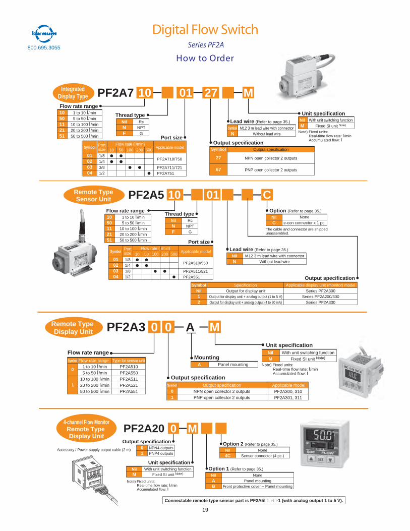
How to Order
Digital Flow Switch800.695.3055
PF2A7 10 01 27
SymbolN
Lead wire (Refer to page 35.)
M12 3 m lead wire with connectorWithout lead wire
1050112151
Flow rate range1 to 10 l/min5 to 50 l/min
10 to 100 l/min20 to 200 l/min50 to 500 l/min
Symbol
01020304
Port size
1/81/43/81/2
10 50 100 200 500Portsize Applicable model
Flow rate (l/min)Symbol
27
67
Output specificationOutput specification
NPN open collector 2 outputs
PNP open collector 2 outputs
NilM
With unit switching functionFixed SI unit Note)
NilNF
Thread type Unit specificationRc
NPTG
PF2A710/750
PF2A711/721PF2A751
IntegratedDisplay Type M
Note) Fixed units: Real-time flow rate: l/minAccumulated flow: l
Series PF2A
PF2A5Remote TypeSensor Unit 10
1050112151
Flow rate range1 to 10 l/min5 to 50 l/min
10 to 100 l/min20 to 200 l/min50 to 500 l/min
NilNF
Thread typeRc
NPTG
Lead wire (Refer to page 35.)
NilN
M12 3 m lead wire with connectorWithout lead wire
01
Symbol
01020304
Port size
1/81/43/81/2
10 50 100 200 500Portsize Applicable model
Flow rate (l/min)
PF2A510/550
PF2A511/521PF2A551
C
NilC
Option (Refer to page 35.)
Nonee-con connector x 1 pc.
The cable and connector are shippedunassembled.
Output specificationSymbol
Nil12
Output for display unitOutput for display unit + analog output (1 to 5 V)Output for display unit + analog output (4 to 20 mA)
SpecificationSeries PF2A300
Series PF2A200/300Series PF2A300
Applicable display unit (monitor) model
Flow rate range
Output specification
PF2A510PF2A550PF2A511PF2A521PF2A551
Type for sensor unitSymbol
0
1
Flow rate range1 to 10 l/min5 to 50 l/min
10 to 100 l/min20 to 200 l/min50 to 500 l/min
Mounting
Unit specification
A Panel mounting
Symbol
01
Output specificationNPN open collector 2 outputsPNP open collector 2 outputs
Applicable model
NilM
With unit switching functionFixed SI unit Note)
Note) Fixed units:Real-time flow rate: l/minAccumulated flow: l
PF2A3Remote Type Display Unit M
PF2A300, 310PF2A301, 311
PF2A20
Nil4C
Option 2 (Refer to page 35.)
NoneSensor connector (4 pc.)
NilM
Unit specificationWith unit switching function
Fixed SI unit Note)
01
Output specificationNPN4 outputsPNP4 outputs
NilAB
Option 1 (Refer to page 35.)
NonePanel mounting
Front protective cover + Panel mounting
4-channel Flow MonitorRemote Type Display Unit
0 M
Accessory / Power supply output cable (2 m)
Connectable remote type sensor part is PF2A5 - -1 (with analog output 1 to 5 V).
Note) Fixed units:Real-time flow rate: l/minAccumulated flow: l
0 0 A
19
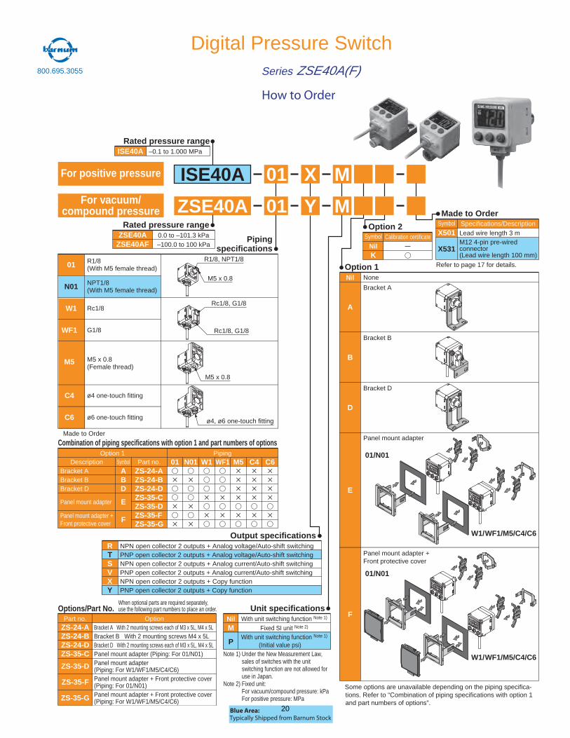
Digital Pressure SwitchSeries ZSE40A(F)
How to Order
ISE40A 01 X M
ZSE40A 01 Y M
Rated pressure rangeISE40A –0.1 to 1.000 MPa
Output specificationsNPN open collector 2 outputs + Analog voltage/Auto-shift switchingPNP open collector 2 outputs + Analog voltage/Auto-shift switchingNPN open collector 2 outputs + Analog current/Auto-shift switchingPNP open collector 2 outputs + Analog current/Auto-shift switchingNPN open collector 2 outputs + Copy functionPNP open collector 2 outputs + Copy function
RTSVXY
Bracket ABracket BBracket D
Panel mount adapter
ZS-24-AZS-24-BZS-24-DZS-35-CZS-35-DZS-35-FZS-35-G
Panel mount adapter + Front protective cover
ABD
E
F
01 N01 W1 WF1 M5 C4 C6Option 1
Description Symbol Part no.Piping
Part no. Option
Rated pressure rangeZSE40A
ZSE40AF0.0 to –101.3 kPa–100.0 to 100 kPa
Made to Order
Option 2Symbol
NilK
Calibration certificate
Symbol
X501
X531
Specifications/DescriptionLead wire length 3 mM12 4-pin pre-wiredconnector(Lead wire length 100 mm)
Unit specifications
Option 1�
Combination of piping specifications with option 1 and part numbers of options
None
Bracket A
A
Bracket B
B
Bracket D
D
Panel mount adapter
01/N01
W1/WF1/M5/C4/C6
W1/WF1/M5/C4/C6
Panel mount adapter + Front protective cover
E
F
Nil
Pipingspecifications
01
N01
W1
WF1�
M5�
C4�
C6�
01/N01
� Some options are unavailable depending on the piping specifica-tions. Refer to “Combination of piping specifications with option 1 and part numbers of options”.
When optional parts are required separately, use the following part numbers to place an order.
Refer to page 17 for details.
Note 1) Under the New Measurement Law, sales of switches with the unit switching function are not allowed for use in Japan.
Note 2) Fixed unit:For vacuum/compound pressure: kPaFor positive pressure: MPa
� Made to Order
For vacuum/compound pressure
For positive pressure
R1/8(With M5 female thread)
NPT1/8(With M5 female thread)
Rc1/8
G1/8
M5 x 0.8(Female thread)
ø4 one-touch fitting
ø6 one-touch fitting
ZS-24-AZS-24-BZS-24-DZS-35-C
ZS-35-D
ZS-35-F
ZS-35-G
Bracket A With 2 mounting screws each of M3 x 5L, M4 x 5LBracket B With 2 mounting screws M4 x 5LBracket D With 2 mounting screws each of M3 x 5L, M4 x 5LPanel mount adapter (Piping: For 01/N01)Panel mount adapter (Piping: For W1/WF1/M5/C4/C6)Panel mount adapter + Front protective cover(Piping: For 01/N01)Panel mount adapter + Front protective cover(Piping: For W1/WF1/M5/C4/C6)
Options/Part No.With unit switching function Note 1)
Fixed SI unit Note 2)
With unit switching function Note 1)
(Initial value psi)
NilM
P
M5 x 0.8
ø4, ø6 one-touch fitting
Rc1/8, G1/8
Rc1/8, G1/8
R1/8, NPT1/8
M5 x 0.8
Blue Area:Typically Shipped from Barnum Stock
800.695.3055
20
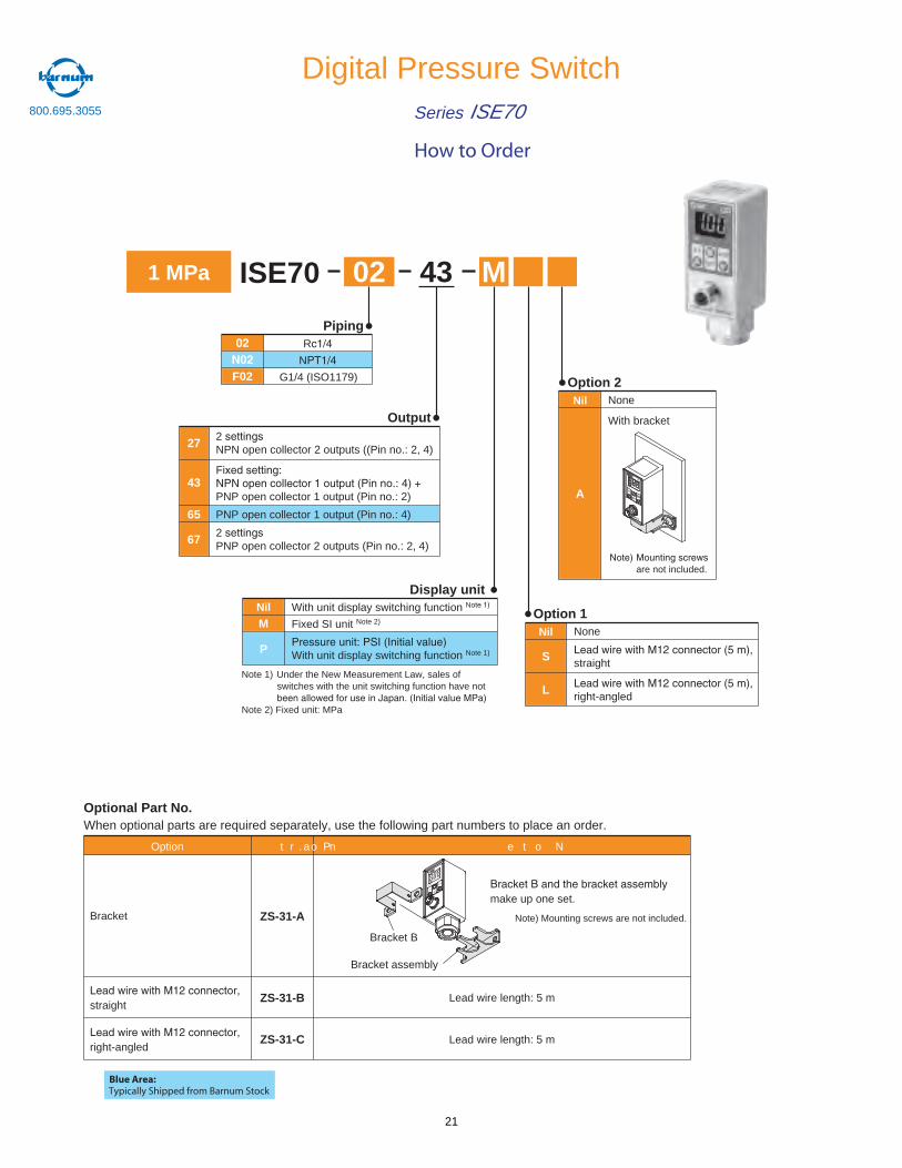
Digital Pressure SwitchSeries ISE70
How to Order
ISE701 MPa 02 43
F02
R
N
G1/4 (ISO1179)
Piping
Nil
M
P
With unit display switching function N
Fixed SI unit Note 2)
With unit display switching function Note 1)
Display unit
Nil
S
None
straight
L right-angled
Option 1
Nil
A
None
With bracket
Option 2
M
43
27
67
65
F
PNP open collector 1 output (Pin no.: 2)
PNP open collector 1 output (Pin no.: 4)
2NPN open collector 2 outputs ((Pin no.: 2, 4)
2PNP open collector 2 outputs (Pin no.: 2, 4)
Output
Note 1) Under the New Measurement Law, sales of switches with the unit switching function have not
Note 2) Fixed unit: MPa
are not included.
Optional Part No.When optional parts are required separately, use the following part numbers to place an order.
Option
Bracket
e t o N. o n t r a P
ZS-31-A
straightLead wire length: 5 mZS-31-B
right-angledLead wire length: 5 mZS-31-C
make up one set.
Bracket B
Bracket assembly
OUT1
U PSET
DOWN
Note) Mounting screws are not included.
Blue Area:Typically Shipped from Barnum Stock
800.695.3055
21
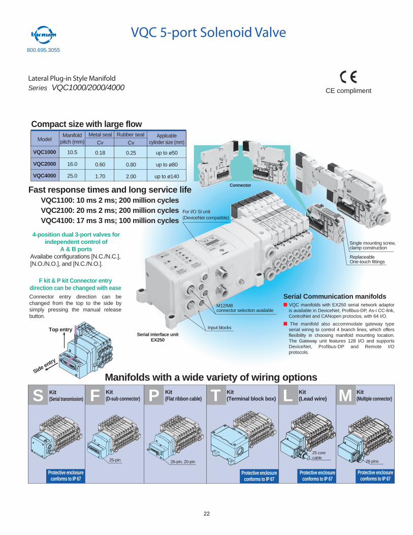
S F T L MPKit(Serial transmission)
Kit(D-sub connector)
Kit(Terminal block box)
Kit(Lead wire)
Kit(Multiple connector)
Kit(Flat ribbon cable)
Protective enclosureconforms to IP 67
Protective enclosureconforms to IP 67
Protective enclosureconforms to IP 67
Protective enclosureconforms to IP 67
25 core cable
26 pins25-pin 26-pin, 20-pin
M12/M8connector selection available
For I/O SI unit(DeviceNet compatible)
Input blocks
Serial interface unitEX250
ReplaceableOne-touch fittings
Single mounting screw,clamp construction
Model
VQC1000
VQC2000
VQC4000
Manifoldpitch (mm)
10.5
16.0
25.0
Metal seal Applicablecylinder size (mm)
up to ø50
up to ø80
up to ø140
Compact size with large flowRubber seal
Cv
0.18
0.60
1.70
Cv
0.25
0.80
2.00
Series
Fast response times and long service lifeVQC1100: 10 ms 2 ms; 200 million cyclesVQC2100: 20 ms 2 ms; 200 million cyclesVQC4100: 17 ms 3 ms; 100 million cycles
Manifolds with a wide variety of wiring options
Top entry
Side entry
Connector
F kit & P kit Connector entry direction can be changed with easeConnector entry direction can be changed from the top to the side by simply pressing the manual release button.
Serial Communication manifolds VQC manifolds with EX250 serial network adaptor is available in DeviceNet, Profibus-DP, As-i CC-link, ControlNet and CANopen protoclos, with 64 I/O.
The manifold also accommodate gateway type serial wiring to control 4 branch lines, which offers flexibility in choosing manifold mounting location. The Gateway unit features 128 I/O and supports DeviceNet, Profibus-DP and Remote I/O protocols.
Lateral Plug-in Style Manifold Series VQC1000/2000/4000
4-position dual 3-port valves for independent control of
A & B portsAvailabe configurations [N.C./N.C.], [N.O./N.O.], and [N.C./N.O.].
CE compliment
55
VQC 5-port Solenoid Valve800.695.3055
22
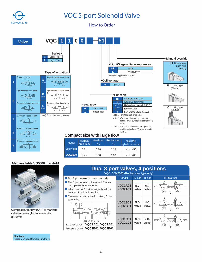
How to Order
VQC 5-port Solenoid Valve800.695.3055
Valve
Nil: Non-lockingpush type
(Slotted)
B: Locking type(Slotted)
C: Locking type(Manual)
R1 A P B R2
VQC1A01VQC2A01
VQC1B01VQC2B01
VQC1C01VQC2C01
Model A side B side JIS Symbol
1(P)
5(R1)
3(R2)
4(A)
2(B)
1(P)
5(R1)
3(R2)
4(A)
2(B)
1(P)
5(R1)
3(R2)
4(A)
2(B)
Dual 3 port valves, 4 positionsVQC1000/2000 (Rubber seal type only)
Two 3 port valves built into one body.
The 3 port valves on the A and B sidescan operate independently.
When used as 3 port valves, only half thenumber of stations is required.
Can also be used as a 4 position, 5 porttype valve.
Exhaust center : VQC1A01, VQC2A01Pressure center: VQC1B01, VQC2B01
N.C.valve
N.C.valve
N.O.valve
N.O.valve
N.C.valve
N.O.valve
Compact large flow (Cv 4.4) manifoldvalve to drive cylinder size up toø180mm
Also available VQ5000 manifold
Blue Area:Typically Shipped from Barnum Stock
Model
VQC1000
VQC2000
Manifoldpitch (mm)
10.5
16.0
Metal seal Applicablecylinder size (mm)
up to ø50
up to ø80
Compact size with large flowRubber seal
Cv
0.18
0.60
Cv
0.25
0.80
12
VQC1000VQC2000
Series
Type of actuation
VQC 1 1 0 51
Coil voltage
Manual override
Seal type
Function
Light/Surge voltage suppressor
Note 1) For metal seal type only.
Note 2) When specifying more than oneoption, enter symbols in alphabeticalorder.
Note 3) R option not available for 4 positiondual 3 port valves. (Type of actuationA, B, C)
2-position single
2-position double (metal)
2-position double (rubber)
3-position closed center
3-position exhaust center
3-position pressure center
1
4-position dual 3-port valve(A)
4-position dual 3-port valve(B)
4-position dual 3-port valve(C)
A
B
C
2
3
4
5
Metal sealRubber seal
Note) Not applicable to S Kit.
01
WithWithout Note)
NilE
Standard type (1W)
High voltage type (1.0MPa)
External pilotLow-wattage type (0.5W)
Nil
K
24VDC5
A B
AE BEP
A B
EA PEB
A B
PEA EB
A B
AE P BE
15 3
4 2
N.C. N.C.
15 3
4 2
N.O. N.O.
15 3
4 2
N.C. N.O.
A B
BEAE P
A B
BEAE P
0
Note)
Note)
Note)
Note 1)
Note) For rubber seal type only.
RY
Note 3)
N Negative Common
23
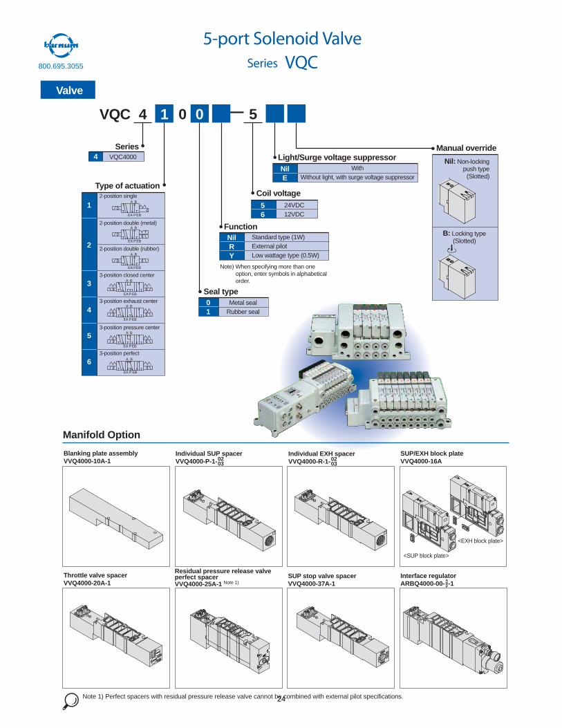
4 VQC4000
Series
Type of actuation
VQC 4 1 0 5
Coil voltage
Manual override
Seal type
Function
Light/Surge voltage suppressor
Note) When specifying more than one option, enter symbols in alphabetical order.
2-position single
2-position double (metal)
2-position double (rubber)
3-position closed center
3-position exhaust center
3-position pressure center
3-position perfect
1
2
3
4Metal seal
Rubber seal
5
6
01
WithWithout light, with surge voltage suppressor
NilE
Standard type (1W)External pilotLow wattage type (0.5W)
NilRY
24VDC12VDC
Nil: Non-lockingpush type
(Slotted)
B: Locking type(Slotted)
A B
PEBEA
A B
EA PEB
A B
PEA EB
A B
EBPEA
A B
PEA EB
A B
PEA EB
A B
EBPEA
0
56
5-port Solenoid ValveSeries VQC
Valve
57
LOCK
PUSH
Manifold Option
0203
Blanking plate assemblyVVQ4000-10A-1
Individual SUP spacerVVQ4000-P-1- 02
03
Individual EXH spacerVVQ4000-R-1-
SUP/EXH block plateVVQ4000-16A
Throttle valve spacerVVQ4000-20A-1
Residual pressure release valveperfect spacerVVQ4000-25A-1 Note 1)
SUP stop valve spacerVVQ4000-37A-1
Interface regulatorARBQ4000-00- -1
ABP
Note 1) Perfect spacers with residual pressure release valve cannot be combined with external pilot specifications.
<EXH block plate>
<SUP block plate>
800.695.3055
24
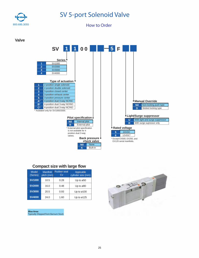
Series
Type of actuation
SV 1 1 0 5
Rated voltage
Pilot specification
Back pressurecheck valve
Light/Surge suppressor
Internal pilotExternal pilot
NilR
With light and surge suppressorWith surge supressor only
UR
NoneBuilt-in
NilK
24VDC12VDC*
F
56
0
SV1000SV2000SV3000SV4000
1234
2-position single solenoid2-position double solenoid3-position closed center3-position exhaust center3-position pressure center4-position dual 3-way NC/NC4-position dual 3-way NO/NO4-position dual 3-way NC/NO
12345A*B*C*
* Except EX500, EX250, andEX120 serial manifolds.
Manual OverrideNon-locking push typeSlotted locking type
NilD
Valve
* External pilot specificationis not available for 4position dual 3-wayvalves.
* Availabel only for SV1000/2000.
63
How to Order
SV 5-port Solenoid Valve
Model(Series)
SV1000
SV2000
SV3000
SV4000
Manifoldpitch (mm)
10.5
16.0
20.5
24.0
Appicablecylinder size (mm)
Up to ø50
Up to ø80
Up to ø100
Up to ø125
Rubber sealCv
0.28
0.48
0.93
1.60
Compact size with large flow
Blue Area:Typically Shipped from Barnum Stock
800.695.3055
25
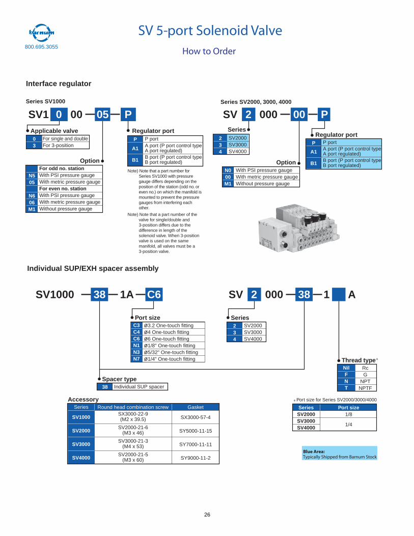
Interface regulator
Series SV1000 Series SV2000, 3000, 4000
SV1 0 00 P
For odd no. stationWith PSI pressure gaugeWith metric pressure gaugeFor even no. stationWith PSI pressure gaugeWith metric pressure gaugeWithout pressure gauge
N505
N606M1
Option
For single and doubleFor 3-position
03
Applicable valveP portA port (P port control typeA port regulated)B port (P port control typeB port regulated)
P
A1
B1
Regulator port
05 SV 2 000 P
With PSI pressure gaugeWith metric pressure gaugeWithout pressure gauge
N000M1
Option
SV2000SV3000SV4000
234
Series
P portA port (P port control typeA port regulated)B port (P port control typeB port regulated)
P
A1
B1
Regulator port
00
Note) Note that a part number forSeries SV1000 with pressuregauge differs depending on theposition of the station (odd no. oreven no.) on which the manifold ismounted to prevent the pressuregauges from interfering eachother.
Note) Note that a part number of thevalve for single/double and3-position differs due to thedifference in length of thesolenoid valve. When 3-positionvalve is used on the samemanifold, all valves must be a3-position valve.
Individual SUP/EXH spacer assembly
SV1000 C638
ø3.2 One-touch fittingø4 One-touch fittingø6 One-touch fittingø1/8" One-touch fittingø5/32" One-touch fittingø1/4" One-touch fitting
C3C4C6N1N3N7
Port size
1A SV 2 000
RcG
NPTNPTF
NilFNT
SeriesSV2000SV3000SV4000
Port size1/8
1/4
Thread type
SV2000SV3000SV4000
234
Series
Individual SUP spacer38
Spacer type
38
Round head combination screwSX3000-22-9(M2 x 39.5)
SV2000-21-6(M3 x 46)
SV3000-21-3(M4 x 53)
SV2000-21-5(M3 x 60)
Gasket
SX3000-57-4
SY5000-11-15
SY7000-11-11
SY9000-11-2
Series
SV1000
SV2000
SV3000
SV4000
Accessory
1 A
Port size for Series SV2000/3000/4000
How to Order
SV 5-port Solenoid Valve
Blue Area:Typically Shipped from Barnum Stock
800.695.3055
26
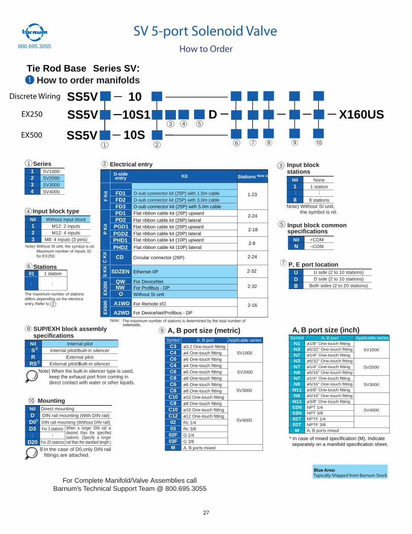
How to order manifolds
Stations
Electrical entry
D-sideentry Kit
FD1FD2FD3PD1PD2
Stations Note 1)
D-sub connector kit (25P) with 1.5m cableD-sub connector kit (25P) with 3.0m cable
:
Note: The maximum number of stations is determined by the total number of
1
4 5
2
3
FK
it
How to Order
PGD1PGD2PHD1PHD2
A, B portSymbolN1N3N7N3N7N9N7N9N11N9N1102N03N02T03TM
ø1/8" One-touch fittingø5/32" One-touch fittingø1/4" One-touch fittingø5/32" One-touch fittingø1/4" One-touch fittingø5/16" One-touch fittingø1/4" One-touch fittingø5/16" One-touch fittingø3/8" One-touch fittingø5/16" One-touch fittingø3/8" One-touch fittingNPT 1/4NPT 3/8NPTF 1/4NPTF 3/8A, B ports mixed
Applicable series
SV1000
SV2000
SV3000
SV4000
A, B port size (inch)
Tie Rod Base Series SV
Discrete Wiring SS5V 10SS5V 10S1 D X160US
SS5V 10S
EX250
EX500
* In case of mixed specification (M), Indicate separately on a manifold specification sheet.
A, B portSymbolC3C4C6C4C6C8C6C8C10C8C10C120203
02F03FM
ø3.2 One-touch fittingø4 One-touch fittingø6 One-touch fittingø4 One-touch fittingø6 One-touch fittingø8 One-touch fittingø6 One-touch fittingø8 One-touch fittingø10 One-touch fittingø8 One-touch fittingø10 One-touch fittingø12 One-touch fittingRc 1/4Rc 3/8G 1/4G 3/8A, B ports mixed
Applicable series
SV1000
SV2000
SV3000
SV4000
01 1 station
The maximum number of stationsdiffers depending on the electrica
l
entry. Refer to
A, B port size (metric)
8 1096
6
123
SV1000SV2000SV3000
SV40004
Series1 2
D-sub connector kit (25P) with 5.0m cableFlat ribbon cable kit (26P) upward
Flat ribbon cable kit (26P) lateral
1-23
2-24
Flat ribbon cable kit (20P) upward2-18
Flat ribbon cable kit (20P) lateralFlat ribbon cable kit (10P) upward
2-8Flat ribbon cable kit (10P) lateral
CD Circular connector (26P) 2-24
QW For DeviceNetNW For Profibus - DP
O Without SI unit
2-32
A1WD For Remote I/O
A2WD For DeviceNet/Profibus - DP
2-16
P K
itE
X25
0C
Kit
EX
500
MountingDirect mountingDIN rail mounting (With DIN rail)DIN rail mounting (Without DIN rail)
NilD
D0D3
D20
For 3 stations
For 20 stations
··· ···
� In the case of D0,only DIN rail fittings are attached.
�
When a longer DIN rail isdesired than the specifiedstations. (Specify a longerrail than the standard length.)
10
None1 station
8 stations
Input block stations
Nil1
8
··· ···
Note) Without SI unit, the symbol is nil.
3
Input block typeWithout input block
M12: 2 inputsM12: 4 inputs
M8: 4 inputs (3 pins)
Nil123
Note) Without SI unit, the symbol is nil.
4
Input block common specifications
+COM–COM
NilN
5
P, E port locationUDB
U side (2 to 10 stations)D side (2 to 10 stations)
Both sides (2 to 20 stations)
SUP/EXH block assemblyspecifications
Internal pilotInternal pilot/Built-in silencer
External pilotExternal pilot/Built-in silencer
NilSR
RS �
�
Note) When the built-in silencer type is used, keep the exhaust port from coming in direct contact with water or other liquids.
8solenoids.
2
S K
it
SDZEN Ethernet I/P 2-32
9
For Complete Manifold/Valve Assemblies call Barnum’s Technical Support Team @ 800.695.3055
Blue Area:Typically Shipped from Barnum Stock
800.695.3055
SV 5-port Solenoid Valve
Maximum number of inputs 32for EX250.
27
Note)
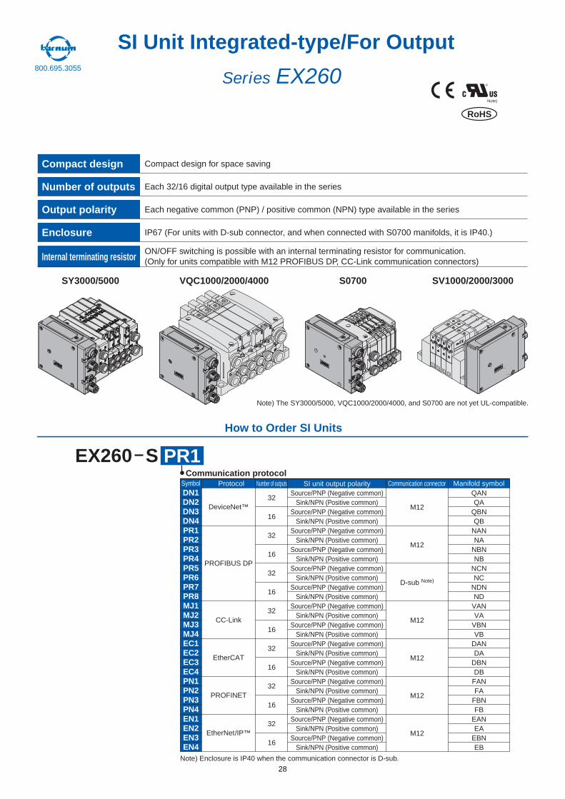
®Series EX260
SI Unit Integrated-type/For Output
M12
DN1DN2DN3DN4PR1PR2PR3PR4PR5PR6PR7PR8MJ1MJ2MJ3MJ4EC1EC2EC3EC4PN1PN2PN3PN4EN1EN2EN3EN4
DeviceNet™
PROFIBUS DP
EtherCAT
PROFINET
Note) Enclosure is IP40 when the communication connector is D-sub.
SI unit output polarity
32
16
32
16
32
16
32
16
32
16
32
16
32
16
M12
M12
D-sub Note)
M12
M12
EtherNet/IP™ M12
Source/PNP (Negative common)Sink/NPN (Positive common)
Source/PNP (Negative common)Sink/NPN (Positive common)
Source/PNP (Negative common)Sink/NPN (Positive common)
Source/PNP (Negative common)Sink/NPN (Positive common)
Source/PNP (Negative common)Sink/NPN (Positive common)
Source/PNP (Negative common)Sink/NPN (Positive common)
Source/PNP (Negative common)Sink/NPN (Positive common)
Source/PNP (Negative common)Sink/NPN (Positive common)
Source/PNP (Negative common)Sink/NPN (Positive common)
Source/PNP (Negative common)Sink/NPN (Positive common)
Source/PNP (Negative common)Sink/NPN (Positive common)
Source/PNP (Negative common)Sink/NPN (Positive common)
Source/PNP (Negative common)Sink/NPN (Positive common)
Source/PNP (Negative common)Sink/NPN (Positive common)
QANQA
QBNQB
NANNA
NBNNB
NCNNC
NDNND
VANVA
VBNVB
DANDA
DBNDB
FANFA
FBNFB
EANEA
EBNEB
Communication protocol
Compact design Compact design for space saving
Number of outputs Each 32/16 digital output type available in the series
Enclosure IP67 (For units with D-sub connector, and when connected with S0700 manifolds, it is IP40.)
Output polarity Each negative common (PNP) / positive common (NPN) type available in the series
Internal terminating resistorON/OFF switching is possible with an internal terminating resistor for communication.(Only for units compatible with M12 PROFIBUS DP, CC-Link communication connectors)
SY3000/5000 VQC1000/2000/4000 S0700 SV1000/2000/3000
DD
DD
How to Order SI Units
PR1EX260 S
Note) The SY3000/5000, VQC1000/2000/4000, and S0700 are not yet UL-compatible.
CC-Link
RoHS
ProtocolSymbol Number of outputs Communication connector Manifold symbol
800.695.3055
28
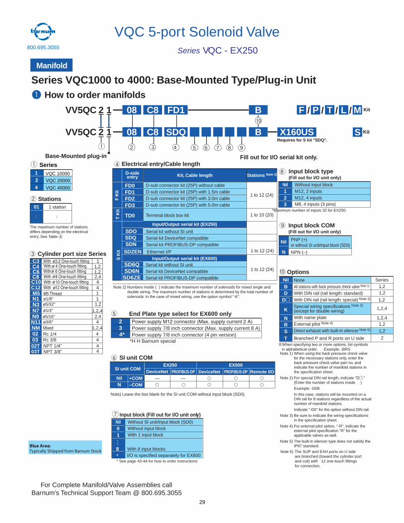
How to order manifolds
Stations01 1 station
OptionsNil None
All stations with back pressure check valve Note 1)
With DIN rail (rail length: standard)With DIN rail (rail length: special) Note 2)
Special wiring specifications Note 3)
(except for double wiring)With name plateExternal pilot Note 4)
Direct exhaust with built-in silencer Note 5)
BD
D
K
NRS
Cylinder port size Series
øø
Series VQC1000 to 4000: Base-Mounted Type/Plug-in Unit
The maximum number of stationsdiffers depending on the electricalentry.
Note 1) When using the back pressure check valvefor the necessary stations only, enter theback pressure check valve part no. andindicate the number of manifold stations inthe specification sheet.
Note 2) For special DIN rail length, indicate "D ."(Enter the number of stations inside .)
Example: -D08
In this case, stations will be mounted on aDIN rail for 8 stations regardless of the actualnumber of manifold stations.
Indicate "-D0" for the option without DIN rail.
Note 3) Be sure to indicate the wiring specificationsin the specification sheet.
Note 4) For external pilot option, "-R", indicate theexternal pilot specification "R" for theapplicable valves as well.
Note 5) The built-in silencer type does not satisfy theIP67 standard.
Input block type(Fill out for I/O unit only)
Nil Without input blockM12, 2 inputsM12, 4 inputsM8, 4 inputs (3 pins)
123
VV5QC 2 1 08 SDQ B
Base-Mounted plug-in
C8
VV5QC 2 1 08 FD1 B
5 6 7
C8
2 3 8
Fill out for I/O serial kit only.
F P T Kit/ /
S Kit
Electrical entry/Cable lengthD-sideentry Kit, Cable length
FD0FD1FD2FD3
TD0
SDQ
D-sub connector kit (25P) without cableD-sub connector kit (25P) with 1.5m cableD-sub connector kit (25P) with 3.0m cableD-sub connector kit (25P) with 5.0m cable
Terminal block box kit 1 to 10 (20)
Stations Note 2)
1 to 12 (24)
1 to 12 (24)
Input/Output serial kit (EX250)
Serial kit without SI unitSerial kit DeviceNet compatibleSerial kit PROFIBUS-DP compatible
Note 2) Numbers inside ( ) indicate the maximum number of solenoids for mixed single anddouble wiring. The maximum number of stations is determined by the total number ofsolenoids. In the case of mixed wiring, use the option symbol "-K".
FK
itT
Kit
SI unit COM
NilN
DeviceNet—
EX500EX250DeviceNetPROFIBUS-DP
—PROFIBUS-DP Remote I/O
SI unit COM
+COM–COM
Note) Leave the box blank for the SI unit COM without input block (SD0).
Input block COM(Fill out for I/O unit only)
Nil PNP (+)or without SI unit/input block (SD0)
NPN (–)N
� When specifying two or more options, list symbolsin alphabetical order. Example: -BRS
/ /L M
Requires for S kit "SDQ".X160US
1 to 12 (24)
Manifold
4
VQC - EX250Series
1
SeriesVQC 10000
24
VQC 20000
VQC 40000
2
3
4
6
8
9
10
10With 4 One-touch fitting
øWith 3.2 One-touch fitting
With 6 One-touch fittingøWith 8 One-touch fitting
C12øWith 10 One-touch fittingøWith 12 One-touch fitting
C3C4C6C8C10
NM Mixed
ø5/32"
N7 ø1/4"
N9 ø5/16"N11
02 Rc 1/4
ø3/8"
03 Rc 3/8
11,21,22,444
1,21,2,42,44
1,2,444
M5 M5 ThreadN1 ø1/8"N3
02T 4403T
11
NPT 1/4”NPT 3/8”
Ethernet I/P
Series1,21,2
1,2
1,2,4
1,2,41,2
1,2
See Table 4
T Branched P and R ports on U side 2
Note 6) The SUP and EXH ports on U sideare branched (toward the cylinder portand coil) with 12 one-touch fittingsfor connection.
800.695.3055
*Maximum number of inputs 32 for EX250.
VQC 5-port Solenoid Valve
Blue Area:Typically Shipped from Barnum Stock
For Complete Manifold/Valve Assemblies call Barnum’s Technical Support Team @ 800.695.3055
S K
it
SDNSDZEN
SD6QSD6N
SD6ZE
Input/Output serial kit (EX600)
SDO
Serial kit without SI unitSerial kit DeviceNet compatibleSerial kit PROFIBUS-DP compatible
9
End Plate type select for EX600 only23 Power supply 7/8 inch connector (Max. supply current 8 A)
5
4* Power supply 7/8 inch connector (4 pin version)*H H Barnum special
Input block (Fill out for I/O unit only)Nil Without SI unit/input block (SD0)
Without input blockWith 1 input block
01
8
7
With 8 input blocks
...
I/O is specified separately for EX600** See page 43-44 for how to order instructions
29
Top ported elbowwith ø3.2 One-touch fitting
Top ported elbowwith ø4 One-touch fitting
Top ported elbowwith ø6 One-touch fitting
—BD
DKNRS
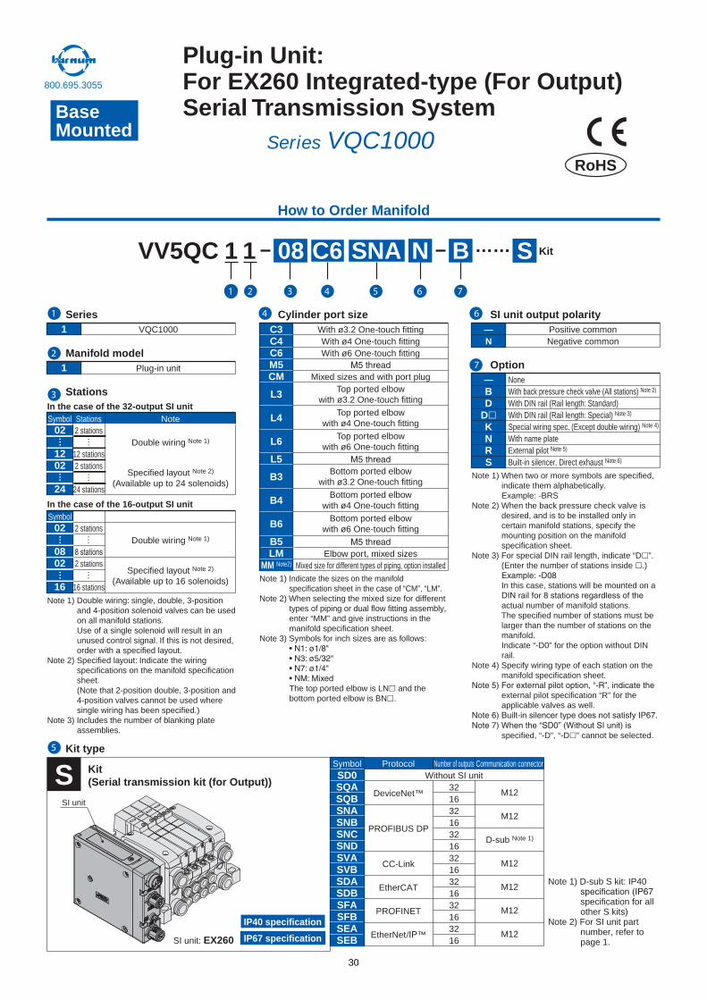
SNAVV5QC 1
Option
S…… KitB
Note 1) Indicate the sizes on the manifold specification sheet in the case of “CM”, “LM”.
Note 2) When selecting the mixed size for different types of piping or dual flow fitting assembly, enter “MM” and give instructions in the manifold specification sheet.
Note 3) Symbols for inch sizes are as follows:
The top ported elbow is LN and the bottom ported elbow is BN .
Note 1) Double wiring: single, double, 3-position and 4-position solenoid valves can be used on all manifold stations.Use of a single solenoid will result in an unused control signal. If this is not desired, order with a specified layout.
Note 2) Specified layout: Indicate the wiring specifications on the manifold specification sheet. (Note that 2-position double, 3-position and 4-position valves cannot be used where single wiring has been specified.)
Note 3) Includes the number of blanking plate assemblies.
NoneWith back pressure check valve (All stations) Note 2)
With DIN rail (Rail length: Standard)With DIN rail (Rail length: Special) Note 3)
Special wiring spec. (Except double wiring) Note 4)
With name plateExternal pilot Built-in silencer, Direct exhaust Note 6)
C3C4C6M5CM
L3
L4
L6
L5
B3
B4
B6
B5LM
MM Note2)
With ø3.2 One-touch fittingWith ø4 One-touch fittingWith ø6 One-touch fitting
Mixed sizes and with port plug
Elbow port, mixed sizesMixed size for different types of piping, option installed
Bottom ported elbowwith ø3.2 One-touch fitting
Bottom ported elbowwith ø4 One-touch fitting
Bottom ported elbowwith ø6 One-touch fitting
Note 1) D-sub S kit: IP40
specification for all other S kits)
Note 2) For SI unit part number, refer to page 1.
SD0SQASQBSNASNBSNCSNDSVASVBSDASDBSFASFBSEASEB
DeviceNet™
PROFIBUS DP
CC-Link
EtherCAT
PROFINET
EtherNet ™
M12
M12
D-sub Note 1)
M12
M12
M12
M12
3216321632163216321632163216
Symbol Protocol Number of outputs Communication connector
S Kit(Serial transmission kit (for Output))
IP67 specification
IP40 specification
SI unit: EX260
SI unit
Note 1) When two or more symbols are specified, indicate them alphabetically.Example: -BRS
Note 2) When the back pressure check valve is desired, and is to be installed only in certain manifold stations, specify the mounting position on the manifold specification sheet.
Note 3) For special DIN rail length, indicate “D ”. (Enter the number of stations inside .)
In this case, stations will be mounted on a
actual number of manifold stations.The specified number of stations must be larger than the number of stations on the manifold.Indicate “-D0” for the option without DIN rail.
Note 4) Specify wiring type of each station on the manifold specification sheet.
external pilot specification “R” for the applicable valves as well.
specified, “-D”, “-D ” cannot be selected.
Cylinder port size1 VQC1000 —
NPositive commonNegative common
Series
1 Plug-in unit Manifold model
SI unit output polarity
Kit type
Without SI unit
Stations
How to Order Manifold
Symbol02
1202
24
Stations Note2 stations
12 stations2 stations
24 stations
Double wiring Note 1)
Specified layout Note 2)
(Available up to 24 solenoids)
…… …
…
In the case of the 32-output SI unit
Symbol02
0802
16
Stations Note2 stations
2 stations
16 stations
Double wiring Note 1)
Specified layout Note 2)
(Available up to 16 solenoids)
In the case of the 16-output SI unit
RoHS
……
……
Series VQC1000BaseMounted
Plug-in Unit:For EX260 Integrated-type (For Output) Serial Transmission System
1
2
3
4 6
7
1 2 3 4
5
5 6 7
1 08 C6 N
800.695.3055
30
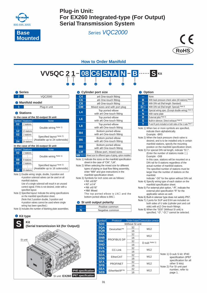
SD0SQASQBSNASNBSNCSNDSVASVBSDASDBSFASFBSEASEB
DeviceNet™
PROFIBUS DP
CC-Link
EtherCAT
PROFINET
EtherNet/IP™
M12
M12
D-sub Note 1)
M12
M12
M12
M12
3216321632163216321632163216
Symbol Protocol Number of outputs Communication connectorWithout SI unit
SI unit
Top ported elbowwith ø4 One-touch fitting
Top ported elbowwith ø6 One-touch fitting
Top ported elbowwith ø8 One-touch fitting
—BD
DKNRST
08 NSNAVV5QC 2
Option
S KitB
Note 1) Indicate the sizes on the manifold specification sheet in the case of “CM”, “LM”.
Note 2) When selecting the mixed size for different types of piping or dual flow fitting assembly, enter “MM” and give instructions in the manifold specification sheet.
Note 3) Symbols for inch sizes are as follows:
The top ported elbow is LN and the bottom ported elbow is BN .
NoneWith back pressure check valve (All stations) Note 2)
With DIN rail (Rail length: Standard)With DIN rail (Rail length: Special) Note 3)
Special wiring spec. (Except double wiring) Note 4)
With name plateExternal pilot Built-in silencer, Direct exhaust Note 6)
P and R ports included on both sides of the U side
C4C6C8CM
L4
L6
L8
B4
B6
B8
LMMM Note 2)
ø4 One-touch fittingø6 One-touch fittingø8 One-touch fitting
Mixed sizes and with port plug
Elbow port, mixed sizesMixed size for different types of piping, option installed
Bottom ported elbowwith ø4 One-touch fitting
Bottom ported elbowwith ø6 One-touch fitting
Bottom ported elbowwith ø8 One-touch fitting
Note 1) D-sub S kit: IP40
specification for all other S kits)
Note 2) For SI unit part number, refer to page 1.
S Kit(Serial transmission kit (for Output))
IP40 specification
IP67 specificationSI unit: EX260
Cylinder port size2 VQC2000
—N
Positive commonNegative common
Series
1 Plug-in unit Manifold model
SI unit output polarity
Kit type
Note 1) When two or more symbols are specified, indicate them alphabetically.Example: -BRS
Note 2) When the back pressure check valve is desired, and is to be installed only in certain manifold stations, specify the mounting position on the manifold specification sheet.
Note 3) For special DIN rail length, indicate “D ”. (Enter the number of stations inside .)Example: -D08In this case, stations will be mounted on a DIN rail for 8 stations regardless of the actual number of manifold stations.The specified number of stations must be larger than the number of stations on the manifold.Indicate “-D0” for the option without DIN rail.
Note 4) Specify wiring type of each station on the manifold specification sheet.
external pilot specification “R” for the applicable valves as well.
2 ports for SUP and EXH are included on both sides of U side (cylinder port and coil side) with ø12 One-touch fittings.
Note 8) When the “SD0” (Without SI unit) is specified, “-D”, “-D ” cannot be selected.
How to Order Manifold
Stations
Symbol02
1202
24
Stations Note2 stations
12 stations2 stations
24 stations
Double wiring Note 1)
Specified layout Note 2)
(Available up to 24 solenoids)
In the case of the 32-output SI unit
Stations2 stations
8 stations2 stations
16 stations
Note
Double wiring Note 1)
Specified layout Note 2)
(Available up to 16 solenoids)
Symbol02
0802
16
In the case of the 16-output SI unit
Note 1) Double wiring: single, double, 3-position and 4-position solenoid valves can be used on all manifold stations.Use of a single solenoid will result in an unused control signal. If this is not desired, order with a specified layout.
Note 2) Specified layout: Indicate the wiring specifications on the manifold specification sheet. (Note that 2-position double, 3-position and 4-position valves cannot be used where single wiring has been specified.)
Note 3) Includes the number of blanking plate assemblies.
RoHS
BaseMounted
Plug-in Unit:For EX260 Integrated-type (For Output) Serial Transmission System
Series VQC2000
1
2
3
4
5
6
7
1 2 3 4 5 6 7
1 C6
800.695.3055
31
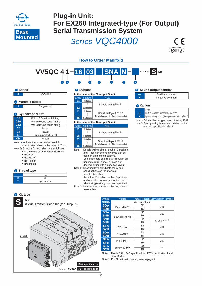
SNAVV5QC 4 S Kit
Note 1) Indicate the sizes on the manifold specification sheet in the case of “CM”.
Note 2) Symbols for inch sizes are as follows:<In the case of One-touch fittings>
C8C10C120203B
CM
—SK
OptionNone
Note 1)
Note 2)
Note 2)
SD0ASQASQBSNASNBSNCSNDSVASVBSDASDBSFASFBSEASEB
™
t
M12
M12
Note 1)
M12
M12
M12
M12
Symbol
S Kit(Serial transmission kit (for Output))
Cylinder port size
4 —N
Series
1 Manifold model
SI unit output polarity
—FT
RcG
Thread type
Kit type
manifold specification sheet.
How to Order Manifold
Stations
Symbol01
1201
16
Stations Note1 station
12 stations1 station
Note 1)
Note 2)
In the case of the 32-output SI unit
Symbol01
0801
16
Stations Note1 station
1 station
Note 1)
Note 2)
In the case of the 16-output SI unit
specifications on the manifold specification sheet.
assemblies.
RoHS
IP40 specification
IP67 specificationEX260
BaseMounted
Plug-in Unit:For EX260 Integrated-type (For Output) Serial Transmission System
Series VQC4000
1
2
3
4
5
6
7
8
0316 N1 1 2 3 4 5 6 7 8
800.695.3055
32

Specifications
Gateway (GW) unit
How to Order
ModelApplicable PLC/Communication protocol
Communication speed
Rated voltage
Current consumptionNo. of input/output pointsNo. of input/output branchesBranch cableBranch cable lengthCommunication connectorPower connectorAmbient operating temperature/humidity
EnclosureApplicable standardWeight (g)
Power supply voltage range
24 VDC
200 mA or less
Maximum 64 inputs/64 outputs
4 branches (16 inputs/16 outputs per branch)
8 core heavy duty cable
5 m or less (total extension 10 m or less)
M12 connector (8 pins, Socket)
M12 connector (5 pins, Plug)
+5 to +45°C/35 to 85% RH (No condensation)
IP65
UL, CSA, CE
470
EX500-GAB1-X1Rockwell Automation, Inc. PLC
57.6 Kbit/sec, 115.2 Kbit/sec230.4 Kbit/sec
EX500-GDN1DeviceNet Release 2.0
125 Kbit/sec, 250 Kbit/sec500 Kbit/sec
EX500-GPR1PROFIBUS-DP
9.6/19.2/93.75/187.5/500 kbit/sec1.5/3/6/12 Mbit/sec
Input and control unit power supply: 24 VDC ±10%Solenoid valve power supply: 24 VDC +10%/–5% (Power drop warning at approx. 20 V)
∗ Communication cables and connectors are sold separately.
EX500 G DN
DNPRAB
Communicationprotocol
DeviceNetPROFIBUS-DP
Remote I/O (RIO)
Nil
-X1
Applicable GW unitDeviceNet
PROFIBUS-DPRemote I/O (RIO)
1
Stations
How to Order Input BlockInput unitmanifold EX500 IE
Nil
-X1
Applicable GW unitDeviceNet
PROFIBUS-DPRemote I/O (RIO)
1
123456
Block typeM8 connector, PNP specificationsM8 connector, NPN specificationsM12 connector, PNP specificationsM12 connector, NPN specifications
8 points integrated type, M8 connector, PNP specifications
8 points integrated type, M8 connector, NPN specifications
How to Order Input Manifold
EEX500 IB1
1
8
1 station
8 stations
Nil
-X1
Applicable GW unitDeviceNet
PROFIBUS-DPRemote I/O (RIO)
E 8
······
ETM
Connector typeM8 connector
M12 connectorM8, M12 mixed
Input unit specifications
Input Unit Specifications
Connection block
Communication connector
Number of connection blocks
Block supply voltage
Block supply current
Current consumption
Short circuit protection
Enclosure
Weight (g)
Current source type input block (PNP input block)or
Current sink type input block (NPN input block)
Operates at 1ATyp. (Power supply cut)GW unit reset by turning power OFF and back ON.
M12 connector (8 pins, plug)
Maximum 8 blocks
24 VDC
0.65 A maximum
100 mA or less (at rated voltage)
IP65
100 (Input block + End Block)
Input Block Specifications
Sensor applicable
Sensor connector
Number of inputs
Rated voltage
Indication
Insulation
Sensor supply current
Enclosure
Weight (g)
Current source type (PNP output)or
Current sink type (NPN output)
M8 connector (3 pins) or, M12 connector (4 pins)
2 inputs/8 inputs (M8 only)
24 VDC
Green LED
None
Maximum 30 mA/Sensor
IP65
[For M8: 20] [For M12: 40] [8 points integrated type, for M8: 55]
EX500 Decentralized Serial WiringSeries SV/VQC800.695.3055
45 33
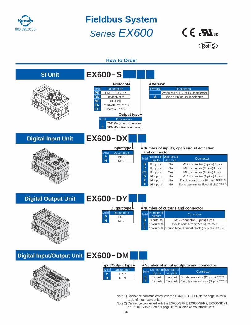
How to Order
006XE S
DXEX600
DYEX600
DMEX600
SI Unit
Protocol
PRDNMJENEC
DescriptionPROFIBUS DP
DeviceNet™CC-Link
EtherNet/IP™ Note 1)
EtherCAT Note 1)
Symbol
Output type
12
DescriptionPNP (Negative common)NPN (Positive common)
Symbol
Version
NilA
DescriptionWhen MJ or EN or EC is selected
When PR or DN is selected
Symbol
Digital Input Unit
Input type
PN
DescriptionPNPNPN
SymbolNumber of inputs, open circuit detection, and connector
BC
C1DEF
Number ofinputs
8 inputs8 inputs8 inputs16 inputs16 inputs16 inputs
Open circuitdetection
NoNoYesNoNoNo
Connector
M12 connector (5 pins) 4 pcs.M8 connector (3 pins) 8 pcs.M8 connector (3 pins) 8 pcs.M12 connector (5 pins) 8 pcs.
D-sub connector (25 pins) Note1) 2)
Spring type terminal block (32 pins) Note1) 2)
Symbol
Digital Output Unit
Output type
PN
DescriptionPNPNPN
SymbolNumber of outputs and connector
BEF
Number ofoutputs
8 outputs16 outputs16 outputs
Connector
M12 connector (5 pins) 4 pcs.D-sub connector (25 pins) Note1) 2)
Spring type terminal block (32 pins) Note1) 2)
Symbol
Digital Input/Output Unit
Input/Output type
PN
DescriptionPNPNPN
SymbolNumber of inputs/outputs and connector
EF
Number ofinputs
8 inputs8 inputs
Number ofoutputs
8 outputs8 outputs
Connector
D-sub connector (25 pins) Note1) 2)
Spring type terminal block (32 pins) Note1) 2)
Symbol
®
RoHS
Fieldbus System
Series EX600
Note 1) Cannot be communicated with the EX600-HT1- . Refer to page 15 for a table of mountable units.
Note 2) Cannot be connected with the EX600-SPR1, EX600-SPR2, EX600-SDN1, or EX600-SDN2. Refer to page 15 for a table of mountable units.
800.695.3055
34
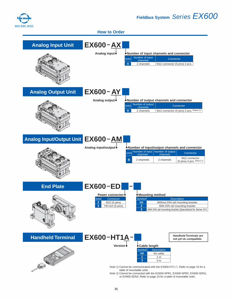
How to Order
AXEX600Analog Input Unit
Analog input Number of input channels and connector
A
Number of inputchannels
2 channels
Connector
M12 connector (5 pins) 2 pcs.
Symbol
AYEX600Analog Output Unit
Analog output Number of output channels and connector
A
Number of outputchannels
2 channels
Connector
M12 connector (5 pins) 2 pcs. Note1) 2)
Symbol
AMEX600Analog Input/Output Unit
Analog input/output Number of input/output channels and connector
B
Number of inputchannels
2 channels
Number of outputchannels
2 channels
Connector
M12 connector(5 pins) 4 pcs. Note1) 2)
Symbol
EDEX600End Plate
HT1AEX600Handheld Terminal
Power connector
23
ConnectorM12 (5 pins)
7/8 inch (5 pins)
SymbolMounting method
Nil23
DescriptionWithout DIN rail mounting bracket
With DIN rail mounting bracketWith DIN rail mounting bracket (Specialized for Series SY)
Symbol
Cable length
Nil13
DescriptionNo cable
1 m3 m
Symbol
Version
Note 1) Cannot be communicated with the EX600-HT1- . Refer to page 15 for a table of mountable units.
Note 2) Cannot be connected with the EX600-SPR1, EX600-SPR2, EX600-SDN1, or EX600-SDN2. Refer to page 15 for a table of mountable units.
Handheld Terminals are not yet UL-compatible.
Fieldbus System Series EX600800.695.3055
35
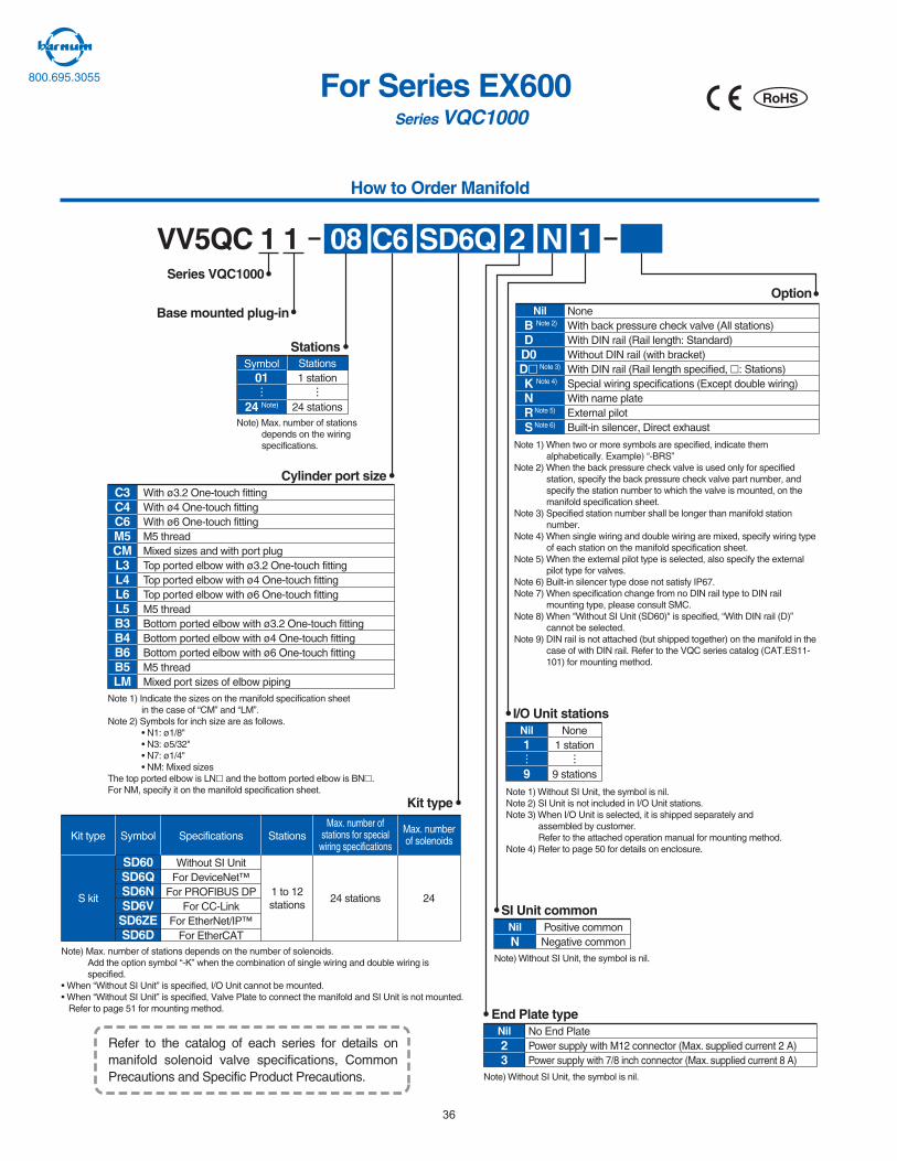
Note 1) When two or more symbols are specified, indicate them alphabetically. Example) “-BRS”
Note 2) When the back pressure check valve is used only for specified station, specify the back pressure check valve part number, and specify the station number to which the valve is mounted, on themanifold specification sheet.
Note 3) Specified station number shall be longer than manifold station number.
Note 4) When single wiring and double wiring are mixed, specify wiring type of each station on the manifold specification sheet.
Note 5) When the external pilot type is selected, also specify the externalpilot type for valves.
Note 6) Built-in silencer type dose not satisfy IP67.Note 7) When specification change from no DIN rail type to DIN rail
mounting type, please consult SMC.Note 8) When "Without SI Unit (SD60)" is specified, “With DIN rail (D)”
cannot be selected.Note 9) DIN rail is not attached (but shipped together) on the manifold in the
case of with DIN rail. Refer to the VQC series catalog (CAT.ES11-101) for mounting method.
Nil NoneWith back pressure check valve (All stations)With DIN rail (Rail length: Standard)Without DIN rail (with bracket)With DIN rail (Rail length specified, : Stations)Special wiring specifications (Except double wiring)With name plateExternal pilotBuilt-in silencer, Direct exhaust
Note 2)
Note 3)
Note 4)
Note 5)
Note 6)
BDD0DKNRS
Option
Base mounted plug-in
Series VQC1000
C6
Stations
Cylinder port size
Kit type
RoHS
How to Order Manifold
For Series EX600Series VQC1000
Symbol01
24 Note)
Stations1 station
24 stationsNote) Max. number of stations
depends on the wiring specifications.
Note 1) Without SI Unit, the symbol is nil.Note 2) SI Unit is not included in I/O Unit stations.Note 3) When I/O Unit is selected, it is shipped separately and
assembled by customer. Refer to the attached operation manual for mounting method.
Note 4) Refer to page 50 for details on enclosure.
1
9
Nil None1 station
9 stations
I/O Unit stations
NNil Positive common
Negative common
SI Unit common
Note) Without SI Unit, the symbol is nil.
23
Nil No End PlatePower supply with M12 connector (Max. supplied current 2 A)Power supply with 7/8 inch connector (Max. supplied current 8 A)
End Plate type
Note) Without SI Unit, the symbol is nil.
C3C4C6M5CML3L4L6L5B3B4B6B5LM
With ø3.2 One-touch fittingWith ø4 One-touch fittingWith ø6 One-touch fittingM5 threadMixed sizes and with port plugTop ported elbow with ø3.2 One-touch fittingTop ported elbow with ø4 One-touch fittingTop ported elbow with ø6 One-touch fittingM5 threadBottom ported elbow with ø3.2 One-touch fittingBottom ported elbow with ø4 One-touch fittingBottom ported elbow with ø6 One-touch fittingM5 threadMixed port sizes of elbow piping
Note 1) Indicate the sizes on the manifold specification sheet in the case of “CM” and “LM”.
Note 2) Symbols for inch size are as follows.• N1: ø1/8"• N3: ø5/32"• N7: ø1/4"• NM: Mixed sizes
The top ported elbow is LN and the bottom ported elbow is BN .For NM, specify it on the manifold specification sheet.
Note) Max. number of stations depends on the number of solenoids.Add the option symbol “-K” when the combination of single wiring and double wiring is specified.
• When “Without SI Unit” is specified, I/O Unit cannot be mounted.• When “Without SI Unit” is specified, Valve Plate to connect the manifold and SI Unit is not mounted.
Refer to page 51 for mounting method.
S kit
Kit type SpecificationsSymbol
Without SI UnitFor DeviceNet™
For PROFIBUS DPFor CC-Link
For EtherNet/IP™For EtherCAT
Stations
1 to 12stations
Max. number ofstations for special
wiring specifications
24 stations
Max. numberof solenoids
24
SD60SD6QSD6NSD6V
SD6ZESD6D
Refer to the catalog of each series for details on manifold solenoid valve specifications, Common Precautions and Specific Product Precautions.
2 N 1SD6Q08VV5QC 1 1
800.695.3055
36
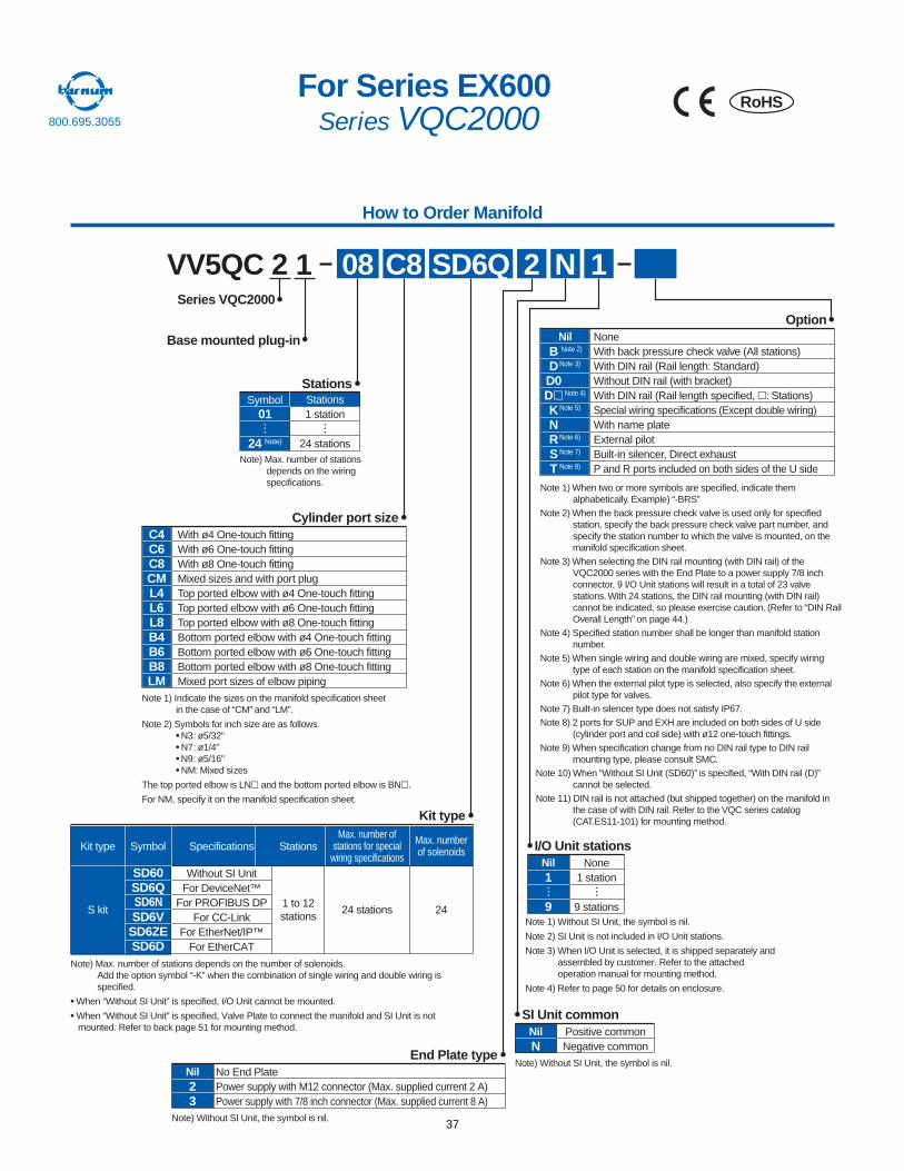
Note 1) When two or more symbols are specified, indicate them alphabetically. Example) “-BRS”
Note 2) When the back pressure check valve is used only for specified station, specify the back pressure check valve part number, and specify the station number to which the valve is mounted, on the manifold specification sheet.
Note 3) When selecting the DIN rail mounting (with DIN rail) of the VQC2000 series with the End Plate to a power supply 7/8 inch connector, 9 I/O Unit stations will result in a total of 23 valve stations. With 24 stations, the DIN rail mounting (with DIN rail) cannot be indicated, so please exercise caution. (Refer to “DIN Rail Overall Length” on page 44.)
Note 4) Specified station number shall be longer than manifold station number.
Note 5) When single wiring and double wiring are mixed, specify wiring type of each station on the manifold specification sheet.
Note 6) When the external pilot type is selected, also specify the external pilot type for valves.
Note 7) Built-in silencer type does not satisfy IP67.Note 8) 2 ports for SUP and EXH are included on both sides of U side
(cylinder port and coil side) with ø12 one-touch fittings.Note 9) When specification change from no DIN rail type to DIN rail
mounting type, please consult SMC.Note 10) When “Without SI Unit (SD60)” is specified, “With DIN rail (D)”
cannot be selected.Note 11) DIN rail is not attached (but shipped together) on the manifold in
the case of with DIN rail. Refer to the VQC series catalog (CAT.ES11-101) for mounting method.
Nil NoneWith back pressure check valve (All stations)With DIN rail (Rail length: Standard)Without DIN rail (with bracket)With DIN rail (Rail length specified, : Stations)Special wiring specifications (Except double wiring)With name plateExternal pilotBuilt-in silencer, Direct exhaustP and R ports included on both sides of the U side
BDD0DKNRST
Option
Note 2)
Note 3)
Note 4)
Note 5)
Note 6)
Note 7)
Note 8)
VV5QC 2 1 08 SD6Q
Base mounted plug-in
Series VQC2000
C8
Stations
Kit type
I/O Unit stations
2 N 1
Note 1) Without SI Unit, the symbol is nil.
Note 2) SI Unit is not included in I/O Unit stations.
Note 3) When I/O Unit is selected, it is shipped separately and assembled by customer. Refer to the attached operation manual for mounting method.
Note 4) Refer to page 50 for details on enclosure.
RoHS
How to Order Manifold
For Series EX600Series VQC2000
Symbol01
24 Note)
Stations1 station
24 stationsNote) Max. number of stations
depends on the wiring specifications.
C4C6C8CML4L6L8B4B6B8LM
With ø4 One-touch fittingWith ø6 One-touch fittingWith ø8 One-touch fittingMixed sizes and with port plugTop ported elbow with ø4 One-touch fittingTop ported elbow with ø6 One-touch fittingTop ported elbow with ø8 One-touch fittingBottom ported elbow with ø4 One-touch fittingBottom ported elbow with ø6 One-touch fittingBottom ported elbow with ø8 One-touch fittingMixed port sizes of elbow piping
Cylinder port size
Note 1) Indicate the sizes on the manifold specification sheet in the case of “CM” and “LM”.
Note 2) Symbols for inch size are as follows.• N3: ø5/32"• N7: ø1/4"• N9: ø5/16"• NM: Mixed sizes
The top ported elbow is LN and the bottom ported elbow is BN .
For NM, specify it on the manifold specification sheet.
Note) Max. number of stations depends on the number of solenoids.Add the option symbol “-K” when the combination of single wiring and double wiring is specified.
• When “Without SI Unit” is specified, I/O Unit cannot be mounted.
• When “Without SI Unit” is specified, Valve Plate to connect the manifold and SI Unit is not mounted. Refer to back page 51 for mounting method.
S kit
Kit type SpecificationsSymbol
Without SI UnitFor DeviceNet™
For PROFIBUS DPFor CC-Link
For EtherNet/IP™For EtherCAT
Stations
1 to 12stations
Max. number ofstations for special
wiring specifications
24 stations
Max. numberof solenoids
24
SD60SD6QSD6NSD6V
SD6ZESD6D
23
Nil No End PlatePower supply with M12 connector (Max. supplied current 2 A)Power supply with 7/8 inch connector (Max. supplied current 8 A)
Note) Without SI Unit, the symbol is nil.
1
9
Nil None1 station
9 stations
End Plate typeNNil Positive common
Negative common
SI Unit common
Note) Without SI Unit, the symbol is nil.
Engineering, Inc.-230 Ryan Way, South San Francisco, CA 94080-6370-Main O�ce: (650) 588-9200-Outside Local Area: (800) 258-9200-www.stevenengineering.com
1
800.695.3055
37
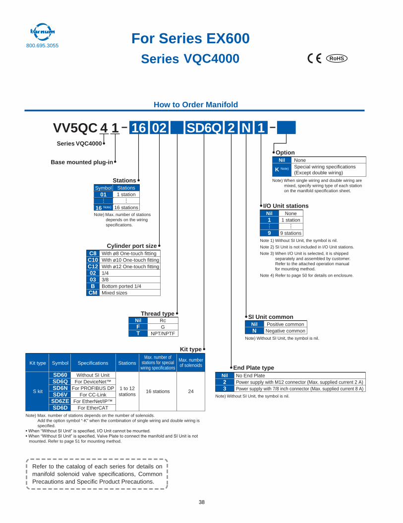
VV5QC 4 1 16 SD6Q
Base mounted plug-in
Series VQC4000
02
Stations
Kit type
End Plate type
SI Unit common
I/O Unit stations
Option
Cylinder port size
NilFT
RcG
NPT/NPTF
Thread type
2 N 1
RoHS
How to Order Manifold
For Series EX600Series VQC4000
Symbol01
16 Note)
Stations1 station
16 stationsNote) Max. number of stations
depends on the wiring specifications.
C8C10C120203B
CM
With ø8 One-touch fittingWith ø10 One-touch fittingWith ø12 One-touch fitting1/43/8Bottom ported 1/4Mixed sizes
Note) When single wiring and double wiring are mixed, specify wiring type of each station on the manifold specification sheet.
Nil NoneSpecial wiring specifications(Except double wiring)
K Note)
1
9
Nil None1 station
9 stations
Note 1) Without SI Unit, the symbol is nil.
Note 2) SI Unit is not included in I/O Unit stations.
Note 3) When I/O Unit is selected, it is shipped separately and assembled by customer. Refer to the attached operation manual for mounting method.
Note 4) Refer to page 50 for details on enclosure.
NNil Positive common
Negative common
Note) Without SI Unit, the symbol is nil.
23
Nil No End PlatePower supply with M12 connector (Max. supplied current 2 A)Power supply with 7/8 inch connector (Max. supplied current 8 A)
Note) Without SI Unit, the symbol is nil.
Note) Max. number of stations depends on the number of solenoids.Add the option symbol “-K” when the combination of single wiring and double wiring is specified.
• When “Without SI Unit” is specified, I/O Unit cannot be mounted.• When “Without SI Unit” is specified, Valve Plate to connect the manifold and SI Unit is not
mounted. Refer to page 51 for mounting method.
S kit
Kit type SpecificationsSymbol
Without SI UnitFor DeviceNet™
For PROFIBUS DPFor CC-Link
For EtherNet/IP™For EtherCAT
Stations
1 to 12stations
Max. number ofstations for special
wiring specifications
16 stations
Max. numberof solenoids
24
SD60SD6QSD6NSD6V
SD6ZESD6D
Refer to the catalog of each series for details on manifold solenoid valve specifications, Common Precautions and Specific Product Precautions.
800.695.3055
38
H.H. Barnum Complete Manifold Assemblies
For complete manifold assemblies please contact our Tech support group at [email protected] with your requirements. Our staff can help you configure a completely assembled and tested manifold with the op ons you need. We will need the following informa on to get started or we can generate a part number and bill of materials from your schema c.
1) Valve series or we can recommend one based on your applica on
• VQC2000 series = 1) Not available with NPT Ports 2) Not available with Interface regulators 3) Largest one touch ngs are 8mm/ 5/16” inch 4) Smallest one touch ngs are 4mm/ 5/32” inch
• VQC4000 series = 1) Available with interface regulators, no dual interface regulator 2) Largest one touch ngs are 10mm/ 3/8” inch 3) Smallest one touch ngs are 6mm/ ¼” inch
• SV2000 series = 1) Not available with NPT Ports 2) Available with interface regulators, no dual interface regulator 3) Largest one touch ngs are 8mm/ 5/16” inch 4) Smallest one touch ngs are 4mm/ 5/32” inch
• SV3000 Series = 1) Not available with NPT ports 2) Available with interface regulators, no dual interface regulator 3) Largest one touch ngs are 10mm/ 3/8” inch 4) Smallest one touch ngs are 6mm/ ¼” inch
2) Number of valves per manifold - The VQC series has 24 available outputs for valves and the SV series has 32 available outputs for valves.
3) Valve configura on on each sta on – we can recommend best prac ce for your applica on if this is not known. • Single solenoid, two posi on, spring return, 5/4 way • Double solenoid, two posi on, detent, 5/4 way • Double solenoid, three posi on, spring center 5/4 way – all ports blocked in the center
posi on • Double solenoid, three posi ons, spring center 5/4 way –exhaust cylinder ports in the
center posi on. • Double solenoid, three posi on, spring center, 5/4 way – pressure to both cylinder ports in
the center posi on
800.695.3055
39

H.H. Barnum Complete Manifold Assemblies800.695.3055
4) Accessories for valve manifold required (sandwich regulators, flow controls, supply spacers etc.)
5) port size and thread type or specify ngs
6) communica on needed • 25 pin D sub – specify cable length (1.5m, 3m, 5m, 10m) • Terminal box • Device net (EX250, EX600,) • Ethernet (EX250, EX600) • Profibus (EX250, EX600) • Profinet (EX245) • Other op ons are available
7) if serial interface is needed then specify type of I/O ( 32 max for EX250, 144 max for EX60 0 on a
single manifold) • Number of Inputs (M8 or M12 connectors) • Number of outputs (M8 0r M12 connectors) • Analog is available for EX600
8) Aux Connector for EX600 = 5pin M12, 5pin MINI, 4pin MINI =
** Manifold is built le to right, unless noted different in drawing **
-continued-
40

41
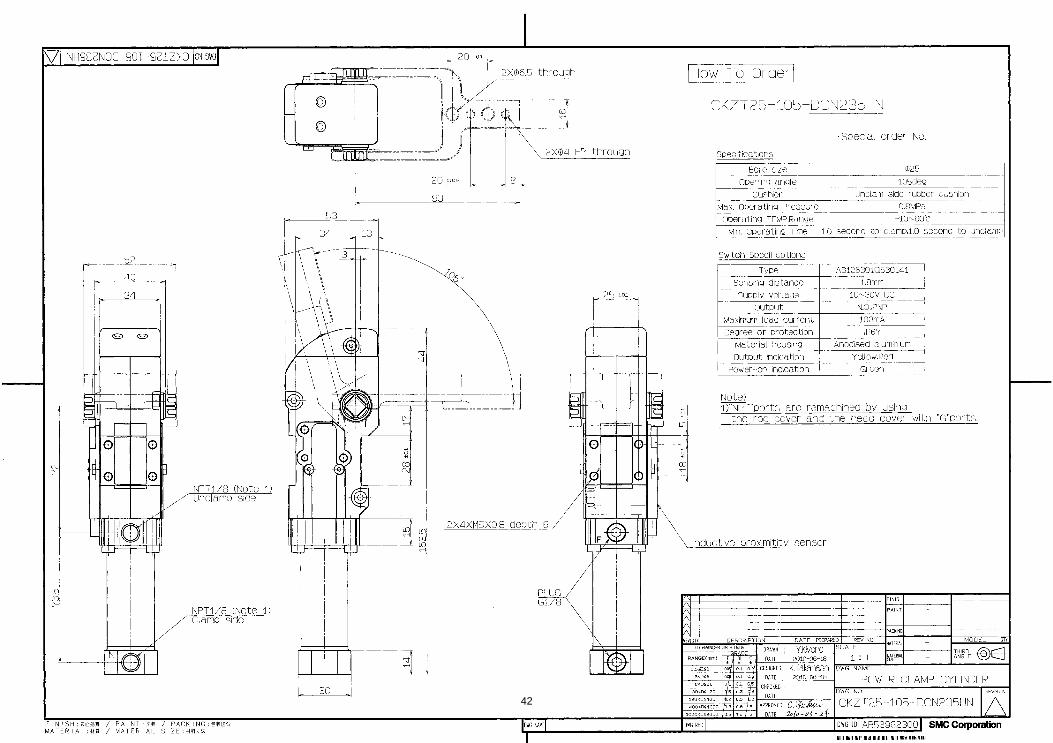
42
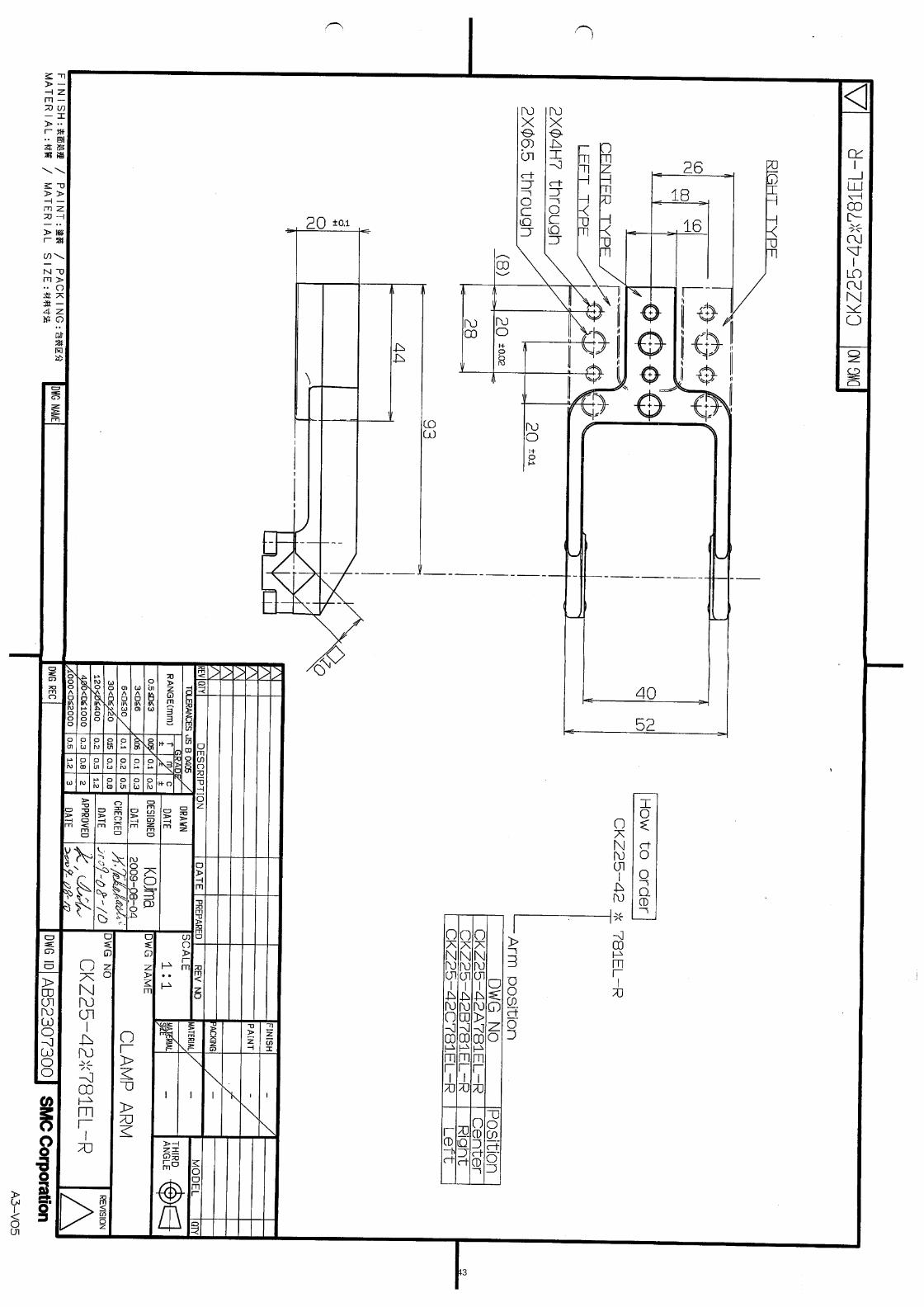
43
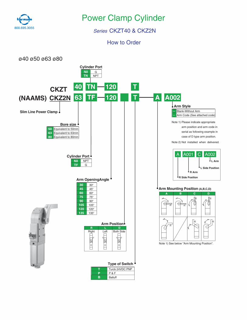
CKZ2N TF A002A63 120 T
A002CA A001
Slim Line Power Clamp
Bore size506380
Equivalent to 50mmEquivalent to 63mmEquivalent to 80mm
Cylinder PortNilTF
NPTG
R Side Position
R Arm
L Arm
L Side Position
––
Arm StyleBlank-Without ArmArm Code (See attached code)
Arm OpeningAngle3045607590105120135
30°45°60°75°90°105°120°135°
Right Left Both Side
Arm PositionLR D
Arm Mounting Position (A,B,C,D)
A B C D
Note 1) Please indicate appropriate
arm position and arm code in
serial as following example in
case of D type arm position.
Note 2) Not installed when delivered.
Type of SwitchTP
Turck 24VDC PNPP & F
Note 1) See below "Arm Mounting Position".
(NAAMS)CKZT 40 TN 120 T
Power Clamp Cylinder
ø40 ø50 ø63 ø80
NilTN NPT
G
Cylinder Port
Series CKZT40 & CKZ2N
How to Order
PB Balluff
800.695.3055
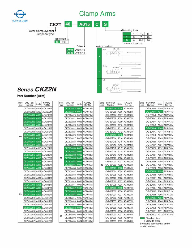
Part Number (Arm)
Boresize
SMC PartNumber Code
A018A019A020A021A022A023A024A025A026A027A028A029A030A031A032A033A034A035A036A037A038A039A040A041A042A043A044A045A046A047A048A001A002A003A004
CKZ-63A018CKZ-63A019CKZ-63A020CKZ-63A021CKZ-63A022CKZ-63A023CKZ-63A024CKZ-63A025CKZ-63A026CKZ-63A027CKZ-63A028CKZ-63A029CKZ-63A030CKZ-63A031CKZ-63A032CKZ-63A033CKZ-63A034CKZ-63A035CKZ-63A036CKZ-63A037CKZ-63A038CKZ-63A039CKZ-63A040CKZ-63A041CKZ-63A042CKZ-63A043CKZ-63A044CKZ-63A045CKZ-63A046CKZ-63A047CKZ-63A048CKZ-80A001CKZ-80A002CKZ-80A003CKZ-80A004
ACA018MACA019MACA020MACA021MACA022MACA023MACA024MACA025MACA026MACA027MACA028MACA029MACA030MACA031MACA032MACA033MACA034MACA035MACA036MACA037MACA038MACA039MACA040MACA041MACA042MACA043MACA044MACA045MACA046MACA047MACA048MACA100MACA101MACA102MACA103M
NAAMSRef No.
63
80
Boresize
SMC PartNumber Code
A005A006A007A008A009A010A011A012A013A014A015A016A017A018A019A020A021A022A023A024A025A026A027A028A029A030A031A032A033A034A035A036A037A038A039
CKZ-80A005CKZ-80A006CKZ-80A007CKZ-80A008CKZ-80A009CKZ-80A010CKZ-80A011CKZ-80A012CKZ-80A013CKZ-80A014CKZ-80A015CKZ-80A016CKZ-80A017CKZ-80A018CKZ-80A019CKZ-80A020CKZ-80A021CKZ-80A022CKZ-80A023CKZ-80A024CKZ-80A025CKZ-80A026CKZ-80A027CKZ-80A028CKZ-80A029CKZ-80A030CKZ-80A031CKZ-80A032CKZ-80A033CKZ-80A034CKZ-80A035CKZ-80A036CKZ-80A037CKZ-80A038CKZ-80A039
ACA104MACA105MACA106MACA107MACA108MACA110MACA111MACA112MACA113MACA114MACA115MACA116MACA117MACA118MACA120MACA121MACA122MACA123MACA124MACA125MACA126MACA127MACA128MACA130MACA131MACA132MACA133MACA134MACA135MACA136MACA137MACA138MACA140MACA141MACA142M
NAAMSRef No.
80
Boresize
SMC PartNumber Code
A001A002A003A004A005A006A007A008A009A010A011A012A013A014A015A016A017A018A001A002A003A004A005A006A007A008A009A010A011A012A013A014A015A016A017
CKZ-50A001CKZ-50A002CKZ-50A003CKZ-50A004CKZ-50A005CKZ-50A006CKZ-50A007CKZ-50A008CKZ-50A009CKZ-50A010CKZ-50A011CKZ-50A012CKZ-50A013CKZ-50A014CKZ-50A015CKZ-50A016CKZ-50A017CKZ-50A018CKZ-63A001CKZ-63A002CKZ-63A003CKZ-63A004CKZ-63A005CKZ-63A006CKZ-63A007CKZ-63A008CKZ-63A009CKZ-63A010CKZ-63A011CKZ-63A012CKZ-63A013CKZ-63A014CKZ-63A015CKZ-63A016CKZ-63A017
ACA201MACA202MACA203MACA206MACA207MACA208MACA211MACA212MACA213MACA216MACA217MACA218MACA221MACA222MACA223MACA226MACA227MACA228MACA001MACA002MACA003MACA004MACA005MACA006MACA007MACA008MACA009MACA010MACA011MACA012MACA013MACA014MACA015MACA016MACA017M
NAAMSRef No.
50
63
Boresize
SMC PartNumber Code
A040A041A042A043A044A045A046A047A048A049A050A051A052A053A054A055A056A057A058A059A060A061A062A063A064A065A066A067A068A069A070A071A072
CKZ-80A040CKZ-80A041CKZ-80A042CKZ-80A043CKZ-80A044CKZ-80A045CKZ-80A046CKZ-80A047CKZ-80A048CKZ-80A049CKZ-80A050CKZ-80A051CKZ-80A052CKZ-80A053CKZ-80A054CKZ-80A055CKZ-80A056CKZ-80A057CKZ-80A058CKZ-80A059CKZ-80A060CKZ-80A061CKZ-80A062CKZ-80A063CKZ-80A064CKZ-80A065CKZ-80A066CKZ-80A067CKZ-80A068CKZ-80A069CKZ-80A070CKZ-80A071CKZ-80A072
ACA143MACA144MACA145MACA146MACA147MACA148MACA150MACA151MACA152MACA153MACA154MACA155MACA156MACA157MACA158MACA160MACA161MACA162MACA163MACA164MACA165MACA166MACA167MACA168MACA170MACA171MACA172MACA173MACA174MACA175MACA176MACA177MACA178M
NAAMSRef No.
80
Standard itemMade to order
Symbol is described at end ofmodel number.
Series CKZ2N
CKZTPower clamp cylinder
European type
A015 C S
Bore size
40
ø4040
OffsetA015A045
Offset 15Offset 45
Arm position
R
Right
C
Center
L
Left
H
øD1
øD2
H
øD1 øD2
øD1
H
øD2
Mounting hole
D D HS* 6 7 16B 8 10.2 20
1 2
* For A015, S Type only
Clamp Arms800.695.3055
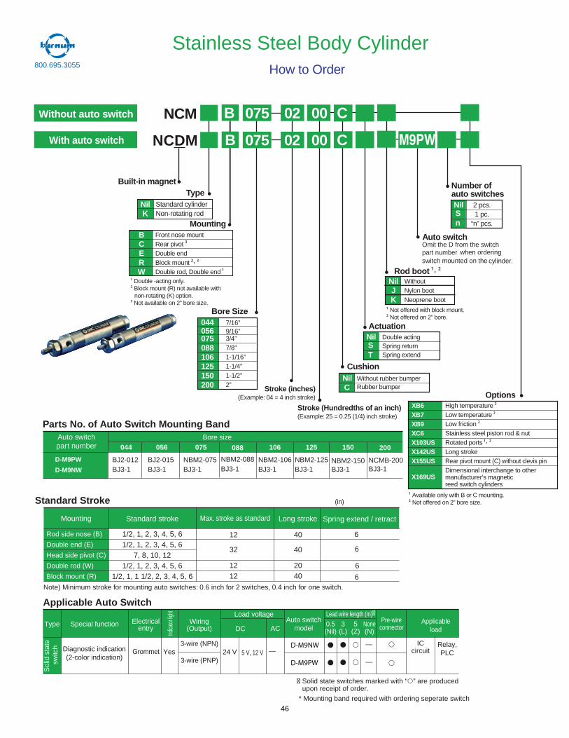
NCDM
Without rubber bumperRubber bumper
WithoutNylon bootNeoprene boot
High temperatureLow temperatureLow frictionStainless steel piston rod & nutRotated ports ,
Long strokeRear pivot mount (C) without clevis pinDimensional interchange to othermanufacturer’s magneticreed switch cylinders
Bore Size
075088106125150200
3/4”7/8”1-1/16”1-1/4”1-1/2”2”
NilC
Cushion
Rod boot ,NilJK
OptionsXB6XB7XB9XC6X103USX142USX155US
X169US
Built-in magnet
MountingBCERW
Front nose mountRear pivotDouble endBlock mount ,
Double rod, Double end
Number ofauto switches
Auto switch
TypeNilK
Standard cylinderNon-rotating rod
Double -acting only.Block mount (R) not available withnon-rotating (K) option.Not available on 2” bore size.
Not offered with block mount.Not offered on 2” bore.
Available only with B or C mounting.Not offered on 2” bore size.
Double actingSpring returnSpring extend
NilST
Actuation
B C
CNCM B 075 02 00
With auto switch
Without auto switch
2 pcs.1 pc.
“n” pcs.
NilSn
02 00075
Stainless Steel Body CylinderHow to Order
Standard Stroke
Mounting
Rod side nose (B)
Double end (E)
Head side pivot (C)
Double rod (W)
Block mount (R)
Standard stroke
1/2, 1, 2, 3, 4, 5, 61/2, 1, 2, 3, 4, 5, 6
7, 8, 10, 121/2, 1, 2, 3, 4, 5, 6
1/2, 1, 1 1/2, 2, 3, 4, 5, 6
Long stroke
12
32
1212
40
40
2040
Note) Minimum stroke for mounting auto switches: 0.6 inch for 2 switches, 0.4 inch for one switch.
Max. stroke as standard
(in)
Spring extend / retract
6
6
6
6
Parts No. of Auto Switch Mounting BandAuto switchpart number 075
NBM2-075
088
NBM2-088
Bore size
106
NBM2-106
125
NBM2-125
150
NBM2-150D-M9PW
D-M9NW
Special functionType Electricalentry
Grommet
Indica
tor lig
ht
Wiring(Output)
Load voltage
ACDC0.5(Nil)
3(L)
5(Z)
Applicableload
Applicable Auto Switch
—5 V, 12 VYesDiagnostic indication(2-color indication)
3-wire (NPN)
3-wire (PNP)24 V
Relay,PLC
Auto switchmodel
Sol
idst
ate
switc
h
None(N)
Pre-wireconnector
—
—
Lead wire length (m)�
ICcircuit
� Solid state switches marked with “ ” are produced upon receipt of order.
D-M9NW
D-M9PW
Omit the D from the switchpart number when ordering
cylinder.switch mounted on the
M9PW
* Mounting band required with ordering seperate switch
Stroke (inches)(Example: 04 = 4 inch stroke)
Stroke (Hundredths of an inch)(Example: 25 = 0.25 (1/4) inch stroke)
BJ3-1 BJ3-1 BJ3-1 BJ3-1 BJ3-1
200
NCMB-200BJ3-1
056
BJ2-015BJ3-1
044
BJ2-012BJ3-1
044 7/16”056 9/16”
800.695.3055
46
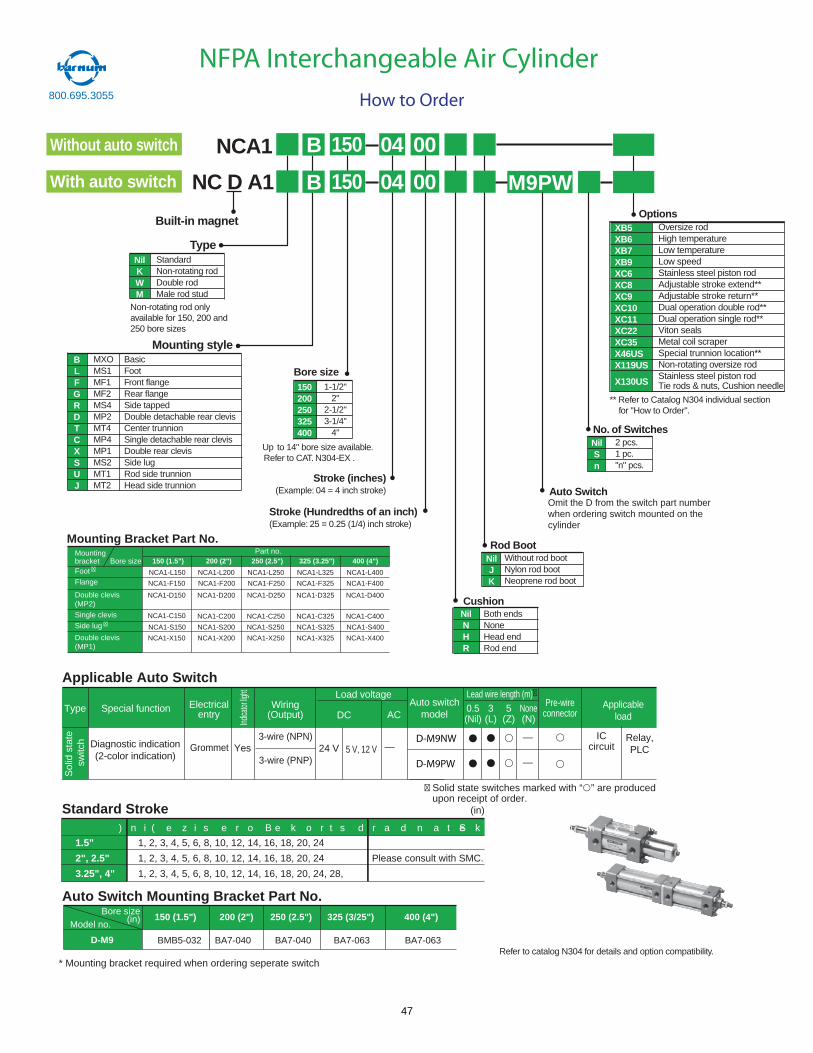
Auto Switch
No. of SwitchesNilSn
Options
Rod Boot
Oversize rodHigh temperatureLow temperatureLow speedStainless steel piston rodAdjustable stroke extend**Adjustable stroke return**Dual operation double rod**Dual operation single rod**Viton sealsMetal coil scraperSpecial trunnion location**Non-rotating oversize rodStainless steel piston rodTie rods & nuts, Cushion needle
XB5XB6XB7XB9XC6XC8XC9XC10XC11XC22XC35X46USX119US
X130US
2 pcs.1 pc."n" pcs.
Without rod bootNylon rod bootNeoprene rod boot
NilJK
Built-in magnet
Bore size150200250325400
1-1/2"2"
2-1/2"3-1/4"
4"
CushionNilNHR
Both endsNoneHead endRod end
Mounting styleBLFGRDTCXSUJ
BasicFootFront flangeRear flangeSide tappedDouble detachable rear clevisCenter trunnionSingle detachable rear clevisDouble rear clevisSide lugRod side trunnionHead side trunnion
NilKWM
StandardNon-rotating rodDouble rodMale rod stud
Type
MXOMS1MF1MF2MS4MP2MT4MP4MP1MS2MT1MT2
NC D A1 00B 150 04
Refer to catalog N304 for details and option compatibility.
Up to 14" bore size available.Refer to CAT. N304-EX .
NCA1 00B 150 04
** Refer to Catalog N304 individual sectionfor "How to Order".
Non-rotating rod onlyavailable for 150, 200 and250 bore sizes
Stroke (inches)(Example: 04 = 4 inch stroke)
Stroke (Hundredths of an inch)(Example: 25 = 0.25 (1/4) inch stroke)
With auto switch
Without auto switch
NFPA Interchangeable Air Cylinder
How to Order
Special functionType Electricalentry
Grommet
Indica
torlig
ht
Wiring(Output)
Load voltage
ACDC0.5(Nil)
3(L)
5(Z)
Applicableload
Applicable Auto Switch
—5 V, 12 VYesDiagnostic indication(2-color indication)
3-wire (NPN)
3-wire (PNP)24 V
Relay,PLC
Auto switchmodel
Sol
idst
ate
switc
h
None(N)
Pre-wireconnector
—
—
Lead wire length (m)�
ICcircuit
� Solid state switches marked with “ ” are produced upon receipt of order.
D-M9NW
D-M9PW
Mounting Bracket Part No.Mountingbracket Bore sizeFoot �
Flange
Double clevis(MP2)
Single clevis
Side lug �
Double clevis(MP1)
NCA1-C150 NCA1-C200 NCA1-C250 NCA1-C325
150 (1.5") 200 (2") 250 (2.5") 325 (3.25")
NCA1-L150 NCA1-L200 NCA1-L250 NCA1-L325
NCA1-F150 NCA1-F200 NCA1-F250 NCA1-F325
NCA1-D150 NCA1-D200 NCA1-D250 NCA1-D325
NCA1-S150 NCA1-S200 NCA1-S250 NCA1-S325
NCA1-X150 NCA1-X200 NCA1-X250 NCA1-X325
NCA1-C400
400 (4")
NCA1-L400
NCA1-F400
NCA1-D400
NCA1-S400
NCA1-X400
Part no.
Standard Strokee k o r t s m u m i x a Me k o r t s d r a d n a t S) n i ( e z i s e r o B
(in)
1.5"
2", 2.5"
3.25", 4"
1, 2, 3, 4, 5, 6, 8, 10, 12, 14, 16, 18, 20, 24
1, 2, 3, 4, 5, 6, 8, 10, 12, 14, 16, 18, 20, 24
1, 2, 3, 4, 5, 6, 8, 10, 12, 14, 16, 18, 20, 24, 28,
Please consult with SMC.
BMB5-032
Bore size (in) Model no.
150 (1.5") 200 (2") 250 (2.5") 325 (3/25") 400 (4")
Auto Switch Mounting Bracket Part No.
D-M9
Omit the D from the switch part numberwhen ordering switch mounted on thecylinder
M9PW
800.695.3055
* Mounting bracket required when ordering seperate switch
BA7-040 BA7-040 BA7-063 BA7-063
47
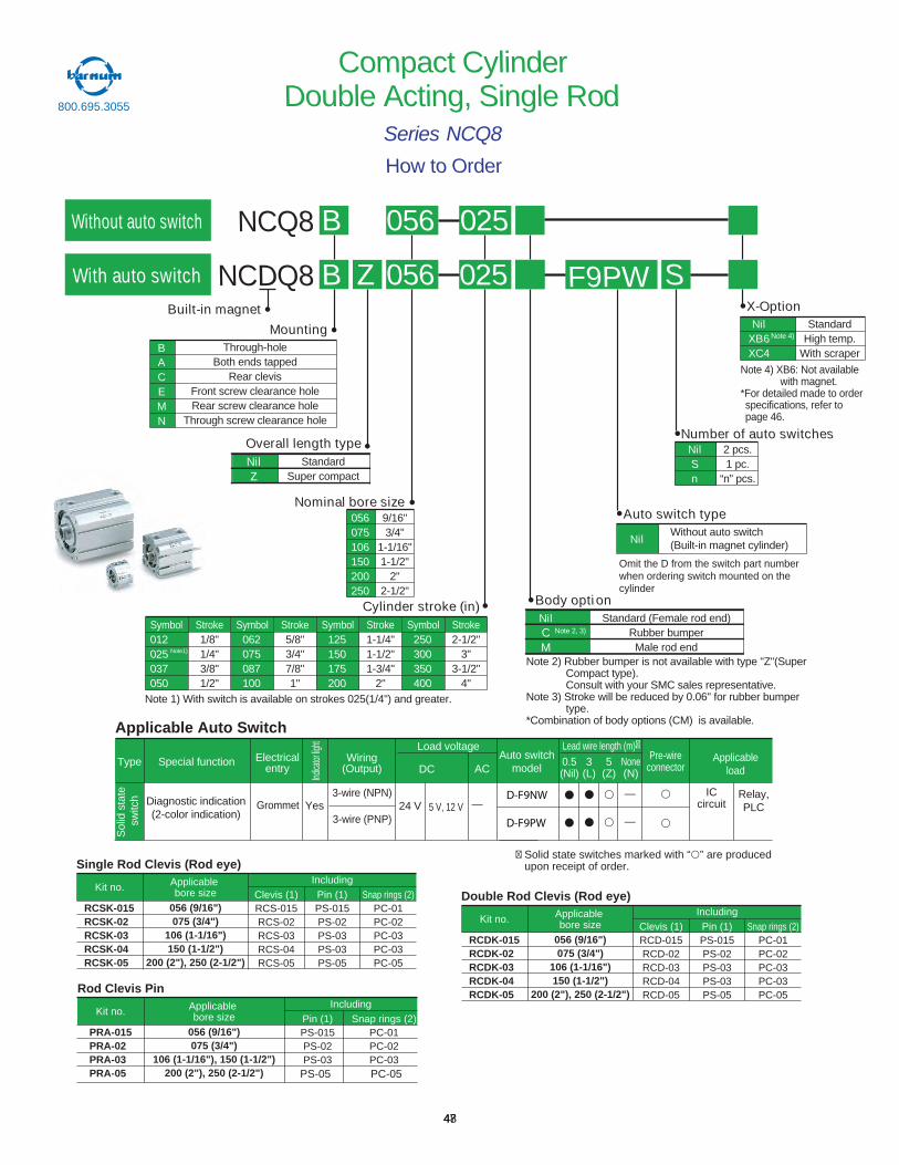
How to Order
Compact CylinderDouble Acting, Single Rod
Series NCQ8
NCQ8
NCDQ8With auto switch
Without auto switch B
B
056
056
025
025Built-in magnet
Nominal bore size9/16"3/4"
1-1/16"1-1/2"
2"2-1/2"
Number of auto switchesNilSn
2 pcs.1 pc.
“n” pcs.
Symbol012025037050
Symbol062075087100
Symbol125150175200
Symbol250300350400
Stroke1/8"1/4"3/8"1/2"
Stroke5/8"3/4"7/8"1"
Stroke1-1/4"1-1/2"1-3/4"
2"
Stroke2-1/2"
3"3-1/2"
4"
Auto switch type
NilWithout auto switch(Built-in magnet cylinder)
MountingBACEMN
Through-holeBoth ends tapped
Rear clevisFront screw clearance holeRear screw clearance hole
Through screw clearance hole
X-OptionNil
XB6XC4
StandardHigh temp.
With scraper
Cylinder stroke (in)
SZ
Overall length typeNilZ
StandardSuper compact
Body optionNilCM
Standard (Female rod end)Rubber bumperMale rod end
Note 2) Rubber bumper is not available with type "Z"(SuperCompact type).Consult with your SMC sales representative.
Note 3) Stroke will be reduced by 0.06" for rubber bumpertype.
*Combination of body options (CM) is available.
Note 1) With switch is available on strokes 025(1/4") and greater.
056075106150200250
Note 4) XB6: Not availablewith magnet.
*For detailed made to orderspecifications, refer topage 46.
Note 4)
Note1)
Note 2, 3)
Special functionType Electricalentry
Grommet
Indica
torlig
ht
Wiring(Output)
Load voltage
ACDC0.5(Nil)
3(L)
5(Z)
Applicableload
Applicable Auto Switch
—5 V, 12 VYesDiagnostic indication(2-color indication)
3-wire (NPN)
3-wire (PNP)24 V
Relay,PLC
Auto switchmodel
Sol
idst
ate
switc
h
None(N)
Pre-wireconnector
—
—
Lead wire length (m)�
ICcircuit
� Solid state switches marked with “ ” are produced upon receipt of order.
D-F9NW
D-F9PW
RCSK-015RCSK-02RCSK-03RCSK-04RCSK-05
Clevis (1)RCS-015RCS-02RCS-03RCS-04RCS-05
Pin (1)PS-015PS-02PS-03PS-03PS-05
Snap rings (2)PC-01PC-02PC-03PC-03PC-05
Applicablebore size
IncludingKit no.
056 (9/16")075 (3/4")
106 (1-1/16")150 (1-1/2")
200 (2"), 250 (2-1/2")
Single Rod Clevis (Rod eye)
PRA-015PRA-02PRA-03PRA-05
Pin (1)PS-015PS-02PS-03
PS-05
Snap rings (2)PC-01PC-02PC-03PC-05
Applicablebore size
IncludingKit no.
056 (9/16")075 (3/4")
106 (1-1/16"), 150 (1-1/2")200 (2"), 250 (2-1/2")
Rod Clevis Pin
RCDK-015RCDK-02RCDK-03RCDK-04RCDK-05
Clevis (1)RCD-015RCD-02RCD-03RCD-04RCD-05
Pin (1)PS-015PS-02PS-03PS-03PS-05
Snap rings (2)PC-01PC-02PC-03PC-03PC-05
Applicablebore size
IncludingKit no.
056 (9/16")075 (3/4")
106 (1-1/16")150 (1-1/2")
200 (2"), 250 (2-1/2")
Double Rod Clevis (Rod eye)
F9PW
800.695.3055
Omit the D from the switch part numberwhen ordering switch mounted on thecylinder
4748
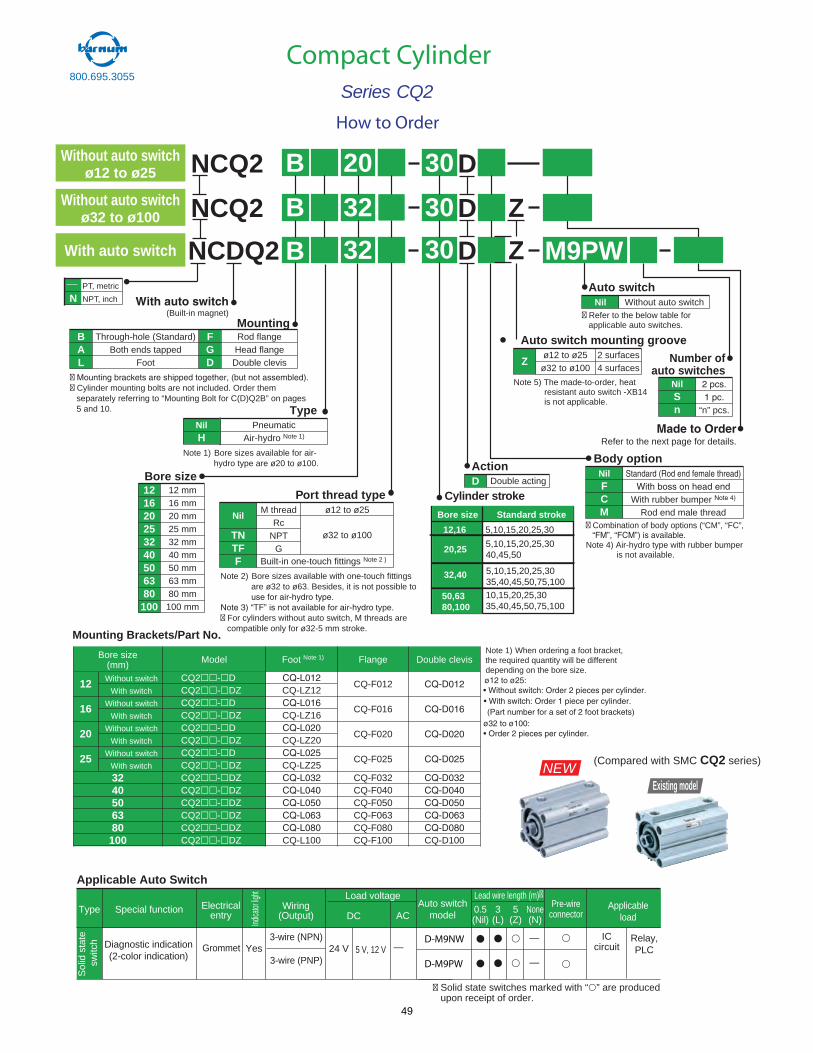
800.695.3055
Compact CylinderSeries CQ2
How to Order
30
30
32
32
(Built-in magnet)
NCQ2 B
BNCDQ2 D
D
M9PW
Bore size121620253240506380
100
12 mm16 mm20 mm25 mm32 mm40 mm50 mm63 mm80 mm
100 mm
Refer to the next page for details.
02 03NCQ2 B D
Z
ZWith auto switch
Without auto switchø12 to ø25
Without auto switchø32 to ø100
Through-hole (Standard)Both ends tapped
Foot
BAL
Rod flangeHead flangeDouble clevis
FGD
Mounting
�� Cylinder mounting bolts are not included. Order them
separately referring to “Mounting Bolt for C(D)Q2B” on pages5 and 10. Type
NilH
PneumaticAir-hydro Note 1)
Note 1) Bore sizes available for air-hydro type are ø20 to ø100.
Built-in one-touch fittings Note 2 )
Note 2) Bore sizes available with one-touch fittings are ø32 to ø63. Besides, it is not possible to
� For cylinders without auto switch, M threads are compatible only for ø32-5 mm stroke.
M threadRc
NPTG
ø12 to ø25
ø32 to ø100
Port thread type
Nil
TNTFF
Note 5) The made-to-order, heat resistant auto switch -XB14 is not applicable.
Auto switch mounting groove
Zø12 to ø25
ø32 to ø1002 surfaces4 surfaces
Auto switch
� Refer to the below table for applicable auto switches.
Nil Without auto switch
Number ofauto switches
NilSn “n” pcs.
Body optionNilFCM
With rubber bumper Rod end male thread
� Combination of body options (“CM”, “FC”,
Note 4) Air-hydro type with rubber bumper is not available.
ActionD Double acting
Cylinder stroke
Bore size Standard stroke
12,16
20,25
32,40
50,6380,100
5,10,15,20,25,30
5,10,15,20,25,3040,45,50
5,10,15,20,25,3035,40,45,50,75,10010,15,20,25,3035,40,45,50,75,100
* Refer to catalog N320 and Best Pn
e
Special functionType Electricalentry
Grommet
Indica
torlig
ht
Wiring(Output)
Load voltage
ACDC0.5(Nil)
3(L)
5(Z)
Applicableload
Applicable Auto Switch
—5 V, 12 VYesDiagnostic indication(2-color indication)
3-wire (NPN)
3-wire (PNP)24 V
Relay,PLC
Auto switchmodel
Sol
idst
ate
switc
h
None(N)
Pre-wireconnector
—
—
Lead wire length (m)�
ICcircuit
� Solid state switches marked with “ ” are produced upon receipt of order.
D-M9NW
D-M9PW
Bore size(mm) Foot Note 1)Model Flange
12
16
20
25
Without switch
With switch
Without switch
With switch
Without switch
With switch
Without switch
With switch
3240506380100
CQ-LZ12
CQ-LZ16
CQ-LZ20
CQ-LZ25
CQ-L100
CQ2 - DCQ2 - DZCQ2 - DCQ2 - DZCQ2 - DCQ2 - DZCQ2 - DCQ2 - DZCQ2 - DZCQ2 - DZCQ2 - DZCQ2 - DZCQ2 - DZCQ2 - DZ
CQ-F012
CQ-F016
CQ-F020
CQ-F025
CQ-F032CQ-F040CQ-F050CQ-F063CQ-F080CQ-F100 CQ-D100
Double clevisNote 1) When ordering a foot bracket,the required quantity will be different depending on the bore size.
Mounting Brackets/Part No.
Existing model
(Compared with SMC CQ2 series)NEW
type.
NPT, metric
NPT, inch
49
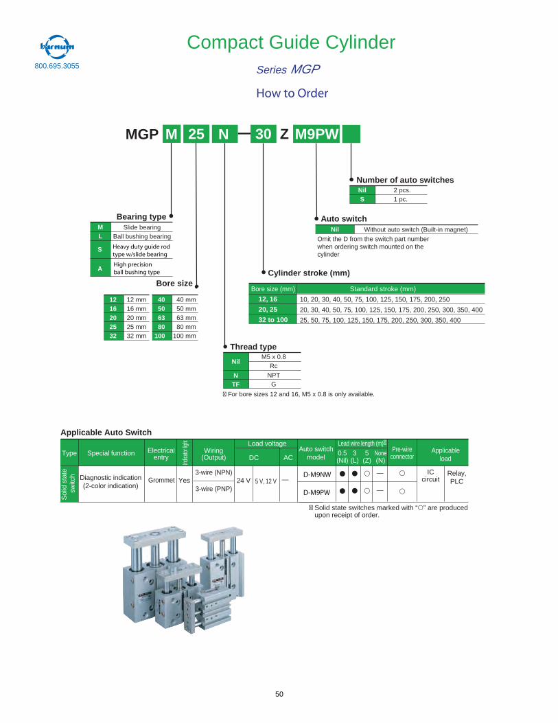
MGP
Compact Guide CylinderSeries MGP
Slide bearingBall bushing bearing
Bore size
NilS
Bearing typeML
Cylinder stroke (mm)
Number of auto switches2 pcs.1 pc.
40506380
100
40 mm50 mm63 mm80 mm
100 mm
1216202532
12 mm16 mm20 mm25 mm32 mm
Auto switchNil
M 25 30 M9PW
Without auto switch (Built-in magnet)
� For bore sizes 12 and 16, M5 x 0.8 is only available.
Nil
Thread typeM5 x 0.8
Rc
NPTG
NTF
Heavy duty guide rodtype w/slide bearing
S
AHigh precisionball bushing type
* Refer to catalog N320 and Best Pn
e
Special functionType Electricalentry
Grommet
Indica
torlig
ht
Wiring(Output)
Load voltage
ACDC0.5(Nil)
3(L)
5(Z)
Applicableload
Applicable Auto Switch
—5 V, 12 VYesDiagnostic indication(2-color indication)
3-wire (NPN)
3-wire (PNP)24 V
Relay,PLC
Auto switchmodel
Sol
idst
ate
switc
h
None(N)
Pre-wireconnector
—
—
Lead wire length (m)�
ICcircuit
� Solid state switches marked with “ ” are produced upon receipt of order.
D-M9PW
D-M9NW
Bore size (mm) Standard stroke (mm)
10, 20, 30, 40, 50, 75, 100, 125, 150, 175, 200, 250
20, 30, 40, 50, 75, 100, 125, 150, 175, 200, 250, 300, 350, 400
25, 50, 75, 100, 125, 150, 175, 200, 250, 300, 350, 400
12, 16
20, 25
32 to 100
How to Order
Omit the D from the switch part numberwhen ordering switch mounted on thecylinder
N Z
800.695.3055
50
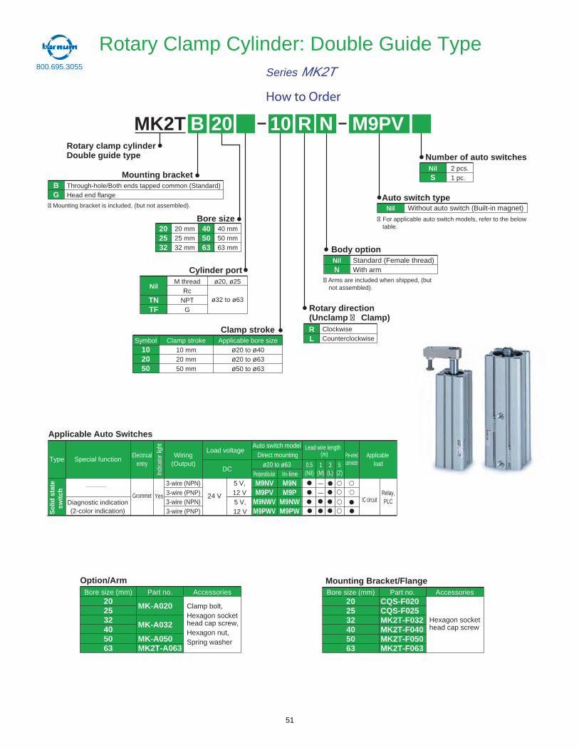
Rotary Clamp Cylinder: Double Guide TypeSeries MK2T
How to Order
800.695.3055
MK2T 10Rotary clamp cylinderDouble guide type Number of auto switches
RB 02
NilS
2 pcs.1 pc.
N
Auto switch type
� For applicable auto switch models, refer to the below table.
� Arms are included when shipped, (but not assembled).
� Mounting bracket is included, (but not assembled). Nil Without auto switch (Built-in magnet)
Body optionNilN
Standard (Female thread)With arm
Rotary direction(Unclamp � Clamp)
Bore size202532
20 mm25 mm32 mm
405063
40 mm50 mm63 mm
Clamp strokeClamp stroke
10 mm20 mm50 mm
Applicable bore sizeø20 to ø40ø20 to ø63ø50 to ø63
Symbol102050
Mounting bracketThrough-hole/Both ends tapped common (Standard)Head end flange
BG
M9PV
M threadRc
NPTG
ø20, ø25
ø32 to ø63
Cylinder port
Nil
TNTF
ClockwiseCounterclockwise
RL
Type Special functionElectrical
entryWiring
(Output)
Load voltage
DC
Lead wire length
0.5(Nil)
3(L)
5(Z)
Applicableload
Pre-wiredconnector1
(M)
Auto switch modelDirect mounting
ø20 to ø63In-linePerpendicular
5 V,12 V
IC circuit
——
Diagnostic indication(2-color indication)
M9NVM9PV
M9NWVM9PWV
M9NM9P
M9NWM9PW
YesGrommet
3-wire (NPN)3-wire (PNP)3-wire (NPN)3-wire (PNP)
24 V Relay,PLC
Indi
cato
r lig
ht
So
lid s
tate
sw
itch
(m)
5 V,12 V
Bore size (mm)202532405063
Accessories
Hexagon sockethead cap screw
Mounting Bracket/Flange Bore size (mm)
202532405063
CQS-F020CQS-F025MK2T-F032MK2T-F040MK2T-F050MK2T-F063
MK-A020
MK-A032
MK-A050MK2T-A063
Accessories
Clamp bolt,Hexagon sockethead cap screw,Hexagon nut,Spring washer
Option/ArmPart no.Part no.
Applicable Auto Switches
51
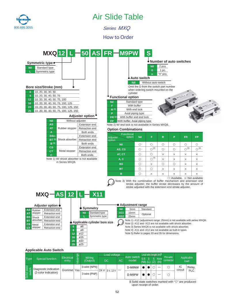
Air Slide TableSeries MXQ
10, 20, 30, 40, 5010, 20, 30, 40, 50, 7510, 20, 30, 40, 50, 75, 10010, 20, 30, 40, 50, 75, 100, 12510, 20, 30, 40, 50, 75, 100, 125, 15010, 20, 30, 40, 50, 75, 100, 125, 150
68
12162025
Bore size/Stroke (mm)
2 pcs.1 pc.
“n” pcs.
NilSn
Number of auto switches
MXQ 12 50 M9PW
Adjuster option
Functional option
AS FR
Extension endRetraction end
Both endsExtension endRetraction end
Both endsExtension endRetraction end
Both ends
ASATA
BS (1)
BT (1)
B (1)
CSCTC
Standard typeWith buffer
With end lockAxial piping type
With buffer and end lockWith buffer, Axial piping type
Nil
Nil
Adjusteroption
Functionaloption
Option Combinations
Auto switchNil Without auto switch
NilNote 2) W/ end lock is not available in Series MXQ6.
F R (2)
P FR (2)
FP
AS, CS
AT, CT
A, C
BS
BT
B
L
Standard typeSymmetric type
NilL
Symmetric type
Without adjuster
Rubber stopper
Shock absorber
Metal stopper
Nil F R P FR FP
: Available, : Not available
(3)
(3)
(3) (3)
Note 1) W/ shock absorber is not availablein Series MXQ6.
Note 3) With the combination of buffer mechanism and extension endstroke adjuster, the buffer stroke decreases by the amount ofstroke adjusted with the extension end stroke adjuster.
* Refer to catalog N320 and Best Pn
e
Special functionType Electricalentry
Grommet
Indica
torlig
ht
Wiring(Output)
Load voltage
ACDC0.5(Nil)
3(L)
5(Z)
Applicableload
Applicable Auto Switch
—5 V, 12 VYesDiagnostic indication(2-color indication)
3-wire (NPN)
3-wire (PNP)24 V
Relay,PLC
Auto switchmodel
Sol
idst
ate
switc
h
None(N)
Pre-wireconnector
—
—
Lead wire length (m)�
ICcircuit
� Solid state switches marked with “ ” are produced upon receipt of order.
D-M9NW
D-M9PW
How to Order
Omit the D from the switch part numberwhen ordering switch mounted on thecylinder
S
Symmetry
Applicable cylinder bore size
Adjustment rangeNil
-X11-X12
MXQ
5mm15mm25mm
6812162025
12 X11
Adjuster option
AS
Standard
Optional
ø6ø8
ø12ø16ø20ø25
L
Standard typeSymmetric type
NilL
Extension endRetraction endExtension endRetraction endExtension endRetraction end
ASATBSBTCSCT
Rubberstopper
Shockabsorber
Metalstopper
Note 1) -X12 (adjustment range: 25mm) is not available with series MXQ6.Note 2) -X11 and -X12 are not available with shock absorber.Note 3) Series MXQ6 is not available with shock absorber.Note 4) -X11 and -X12 are not available as built-in types.Note 5) Refer to pages 33 and 35 for dimensions.
800.695.3055
52
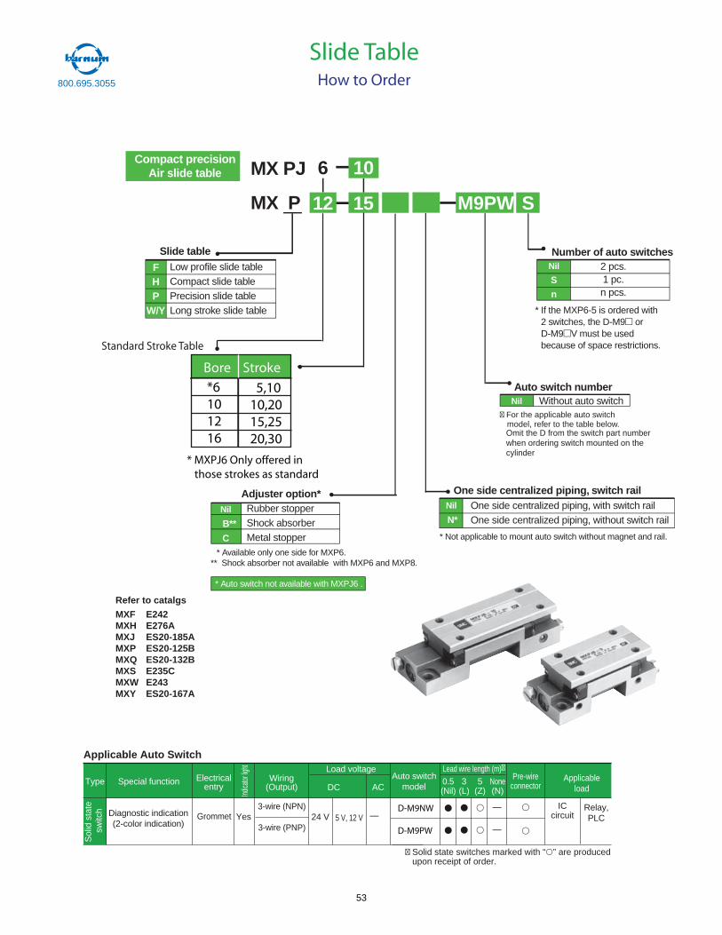
FHP
W/Y
Low profile slide tableCompact slide tablePrecision slide tableLong stroke slide table
Slide table
Nil
N*
One side centralized piping, with switch railOne side centralized piping, without switch rail
MX PJ
MX P
6
M9PW S15
Nil
S
n
2 pcs.1 pc.n pcs.
Nil Without auto switch
Number of auto switches
Auto switch number
One side centralized piping, switch railAdjuster option*Nil
B**
C
Rubber stopperShock absorberMetal stopper
Compact precisionAir slide table
* Auto switch not available with MXPJ6 .
* Available only one side for MXP6.** Shock absorber not available with MXP6 and MXP8.
* Not applicable to mount auto switch without magnet and rail.
* If the MXP6-5 is ordered with2 switches, the D-M9 orD-M9 V must be usedbecause of space restrictions.
12
10
Refer to catalgs
MXF E242MXH E276AMXJ ES20-185AMXP ES20-125BMXQ ES20-132BMXS E235CMXW E243MXY ES20-167A
Slide TableHow to Order
Standard Stroke Table
Bore Stroke
*6101216
5,1010,2015,2520,30
* MXPJ6 Only offered in those strokes as standard
* Refer to catalog N320 and Best Pn
e
Special functionType Electricalentry
Grommet
Indica
torlig
ht
Wiring(Output)
Load voltage
ACDC0.5(Nil)
3(L)
5(Z)
Applicableload
Applicable Auto Switch
—5 V, 12 VYesDiagnostic indication(2-color indication)
3-wire (NPN)
3-wire (PNP)24 V
Relay,PLC
Auto switchmodel
Sol
idst
ate
switc
h
None(N)
Pre-wireconnector
—
—
Lead wire length (m)�
ICcircuit
� Solid state switches marked with “ ” are produced upon receipt of order.
D-M9NW
D-M9PW
� For the applicable auto switchmodel, refer to the table below.Omit the D from the switch part numberwhen ordering switch mounted on thecylinder
800.695.3055
53
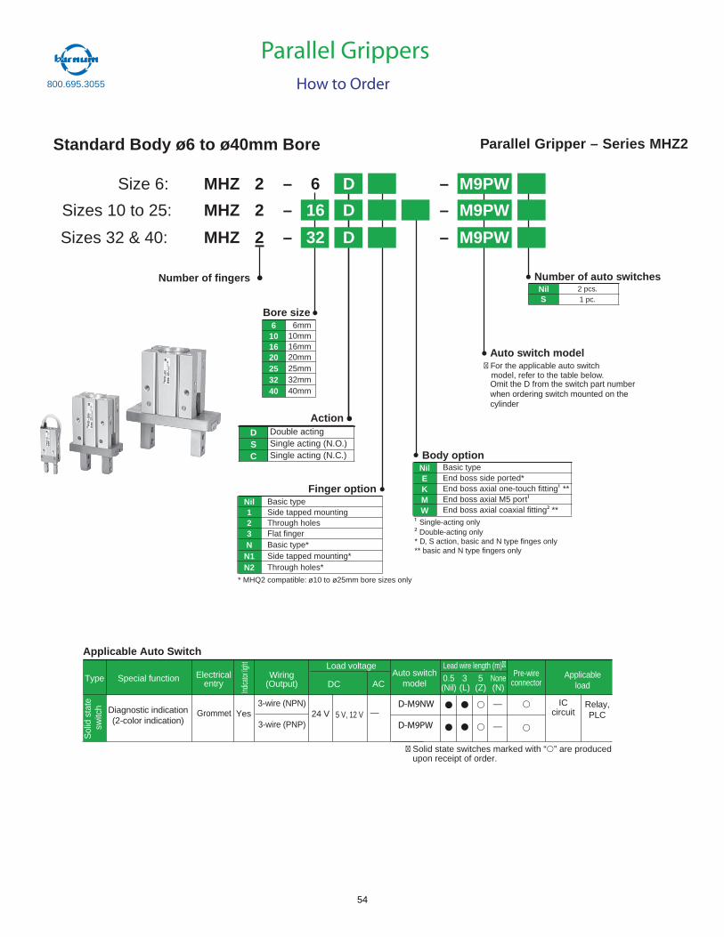
Standard Body ø6 to ø40mm Bore
MHZ 2 – 6 D – M9PW
MHZ 2 – 16 D –
MHZ 2 – 32 D –
Size 6:
Sizes 10 to 25:
Sizes 32 & 40:
Parallel Gripper – Series MHZ2
Number of fingers
Bore size6101620253240
6mm10mm16mm20mm25mm32mm40mm
Double actingSingle acting (N.O.)Single acting (N.C.)
DSC
Action
Finger optionNil123NN1N2
Basic typeSide tapped mountingThrough holesFlat fingerBasic type*Side tapped mounting*Through holes*
* MHQ2 compatible: ø10 to ø25mm bore sizes only
Body optionNilEKMW
Basic typeEnd boss side ported*End boss axial one-touch fitting **End boss axial M5 portEnd boss axial coaxial fitting **
Single-acting only Double-acting only
* D, S action, basic and N type finges only** basic and N type fingers only
Auto switch model
NilS
Number of auto switches2 pcs.1 pc.
Parallel GrippersHow to Order
* Refer to catalog N320 and Best Pn
e
Special functionType Electricalentry
Grommet
Indica
torlig
ht
Wiring(Output)
Load voltage
ACDC0.5(Nil)
3(L)
5(Z)
Applicableload
Applicable Auto Switch
—5 V, 12 VYesDiagnostic indication(2-color indication)
3-wire (NPN)
3-wire (PNP)24 V
Relay,PLC
Auto switchmodel
Sol
idst
ate
switc
h
None(N)
Pre-wireconnector
—
—
Lead wire length (m)�
ICcircuit
� Solid state switches marked with “ ” are produced upon receipt of order.
D-M9PW
D-M9NW
� For the applicable auto switchmodel, refer to the table below.Omit the D from the switch part numberwhen ordering switch mounted on thecylinder
M9PW
M9PW
800.695.3055
54
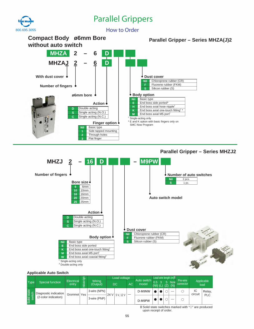
Compact Body ø6mm Borewithout auto switch
MHZA 2 – 6 D
MHZAJ – 6 D
Parallel Gripper – Series MHZA(J)2
Number of fingers
With dust cover
ø6mm bore
Double actingSingle acting (N.O.)Single acting (N.C.)
DSC
Action
Finger optionNil123
Basic typeSide tapped mountingThrough holesFlat finger
Body optionNilEHKM
Basic typeEnd boss side ported*End boss sxial hose nippleEnd boss axial one-touch fitting *End boss axial M5 port
Single-acting only* E and K option with basic fingers only on
SMC Now Program
Dust coverNilFS
Chloroprene rubber (CR)Fluorene rubber (FKM)Silicon rubber (S)
2
MHZJ 2 – 16 D – M9PW
Parallel Gripper – Series MHZJ2
Number of fingers
Bore size610162025
6mm10mm16mm20mm25mm
Double actingSingle acting (N.O.)Single acting (N.C.)
DSC
Action
Body optionNilEKMW
Basic typeEnd boss side portedEnd boss axial one-touch fittingEnd boss axial M5 portEnd boss axial coaxial fitting
Single-acting only Double-acting only
Dust coverNilFS
Chloroprene rubber (CR)Fluorene rubber (FKM)Silicon rubber (S)
Auto switch model
NilS
Number of auto switches2 pcs.1 pc.
Parallel GrippersHow to Order
* Refer to catalog N320 and Best Pn
e
Special functionType Electricalentry
Grommet
Indica
torlig
ht
Wiring(Output)
Load voltage
ACDC0.5(Nil)
3(L)
5(Z)
Applicableload
Applicable Auto Switch
—5 V, 12 VYesDiagnostic indication(2-color indication)
3-wire (NPN)
3-wire (PNP)24 V
Relay,PLC
Auto switchmodel
Sol
idst
ate
switc
h
None(N)
Pre-wireconnector
—
—
Lead wire length (m)�
ICcircuit
� Solid state switches marked with “ ” are produced upon receipt of order.
D-M9PW
D-M9NW
800.695.3055
55
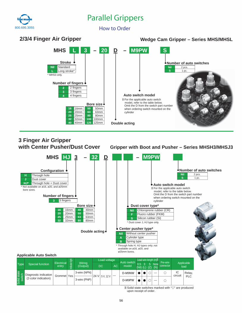
2/3/4 Finger Air Gripper
MHS L 3 – 20 D – S
Wedge Cam Gripper – Series MHS/MHSL
StandardLong stroke*
NilL
Stroke
* MHS3 only.
2 fingers3 fingers4 fingers
234
Number of fingers
Bore size506380100125
50mm63mm80mm
100mm125mm
1620253240
16mm20mm25mm32mm40mm Double acting
Auto switch model
NilS
Number of auto switches2 pcs.1 pc.
MHS HJ 3 – 32 D –
3 Finger Air Gripper with Center Pusher/Dust Cover Gripper with Boot and Pusher – Series MHSH3/MHSJ3
Through holeDust coverThrough hole + Dust cover
HJ
HJ*
Configuration
* Not available on ø16, ø20, and ø25mm bore sizes.
3 fingers3
Number of fingers
Bore size40506380
40mm50mm63mm80mm
16202532
16mm20mm25mm32mm
Double actingWithout center pusherCylinder typeSpring type
NilAB
Center pusher type*
* Through hole H, HJ types only; not available on ø16, ø20, and ø25mm bores.
Chloroprene rubber (CR)Fluoro rubber (FKM)Silicon rubber (Si)
NilFS
Dust cover type*
* Dust cover J, HJ type only.
Auto switch model
NilS
Number of auto switches2 pcs.1 pc.
Parallel GrippersHow to Order
* Refer to catalog N320 and Best Pn
e
Special functionType Electricalentry
Grommet
Indica
torlig
ht
Wiring(Output)
Load voltage
ACDC0.5(Nil)
3(L)
5(Z)
Applicableload
Applicable Auto Switch
—5 V, 12 VYesDiagnostic indication(2-color indication)
3-wire (NPN)
3-wire (PNP)24 V
Relay,PLC
Auto switchmodel
Sol
idst
ate
switc
h
None(N)
Pre-wireconnector
—
—
Lead wire length (m)�
ICcircuit
� Solid state switches marked with “ ” are produced upon receipt of order.
D-M9PW
D-M9NW
M9PW
M9PW
� For the applicable auto switchmodel, refer to the table below.Omit the D from the switch part numberwhen ordering switch mounted on thecylinder
800.695.3055
� For the applicable auto switchmodel, refer to the table below.Omit the D from the switch part numberwhen ordering switch mounted on thecylinder
56
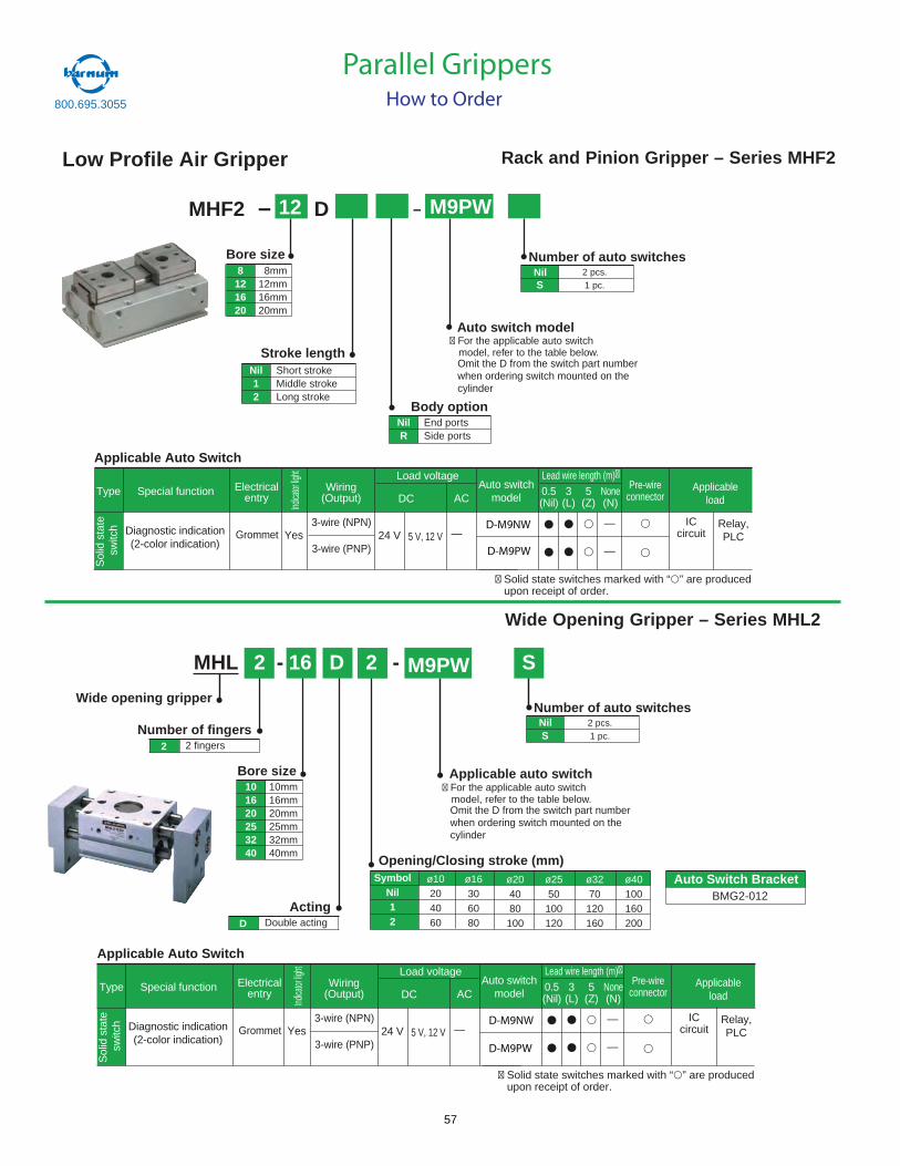
Low Profile Air Gripper
MHF2 – 12 D – M9PW
8121620
8mm12mm16mm20mm
Bore size
Stroke lengthNil12
Short strokeMiddle strokeLong stroke
Body optionNilR
End portsSide ports
Auto switch model
NilS
Number of auto switches2 pcs.1 pc.
Rack and Pinion Gripper – Series MHF2
MHL 2 - 16 D 2 - S
Wide Opening Gripper – Series MHL2
Bore size101620253240
10mm16mm20mm25mm32mm40mm
Double actingActing
D
2 fingersNumber of fingers
2
Wide opening gripper
NilS
Number of auto switches2 pcs.1 pc.
Applicable auto switch
Opening/Closing stroke (mm)Symbol
Nil12
ø10204060
ø16306080
ø204080
100
ø2550
100120
ø3270
120160
ø40100160200
Parallel GrippersHow to Order
* Refer to catalog N320 and Best Pn
e
Special functionType Electricalentry
Grommet
Indica
torlig
ht
Wiring(Output)
Load voltage
ACDC0.5(Nil)
3(L)
5(Z)
Applicableload
Applicable Auto Switch
—5 V, 12 VYesDiagnostic indication(2-color indication)
3-wire (NPN)
3-wire (PNP)24 V
Relay,PLC
Auto switchmodel
Sol
idst
ate
switc
h
None(N)
Pre-wireconnector
—
—
Lead wire length (m)�
ICcircuit
� Solid state switches marked with “ ” are produced upon receipt of order.
D-M9PW
D-M9NW
* Refer to catalog N320 and Best Pn
e
Special functionType Electricalentry
Grommet
Indica
torlig
ht
Wiring(Output)
Load voltage
ACDC0.5(Nil)
3(L)
5(Z)
Applicableload
Applicable Auto Switch
—5 V, 12 VYesDiagnostic indication(2-color indication)
3-wire (NPN)
3-wire (PNP)24 V
Relay,PLC
Auto switchmodel
Sol
idst
ate
switc
h
None(N)
Pre-wireconnector
—
—
Lead wire length (m)�
ICcircuit
� Solid state switches marked with “ ” are produced upon receipt of order.
D-M9NW
D-M9PW
800.695.3055
� For the applicable auto switchmodel, refer to the table below.Omit the D from the switch part numberwhen ordering switch mounted on thecylinder
� For the applicable auto switchmodel, refer to the table below.Omit the D from the switch part numberwhen ordering switch mounted on thecylinder
M9PW
Auto Switch BracketS BMG2-012
57
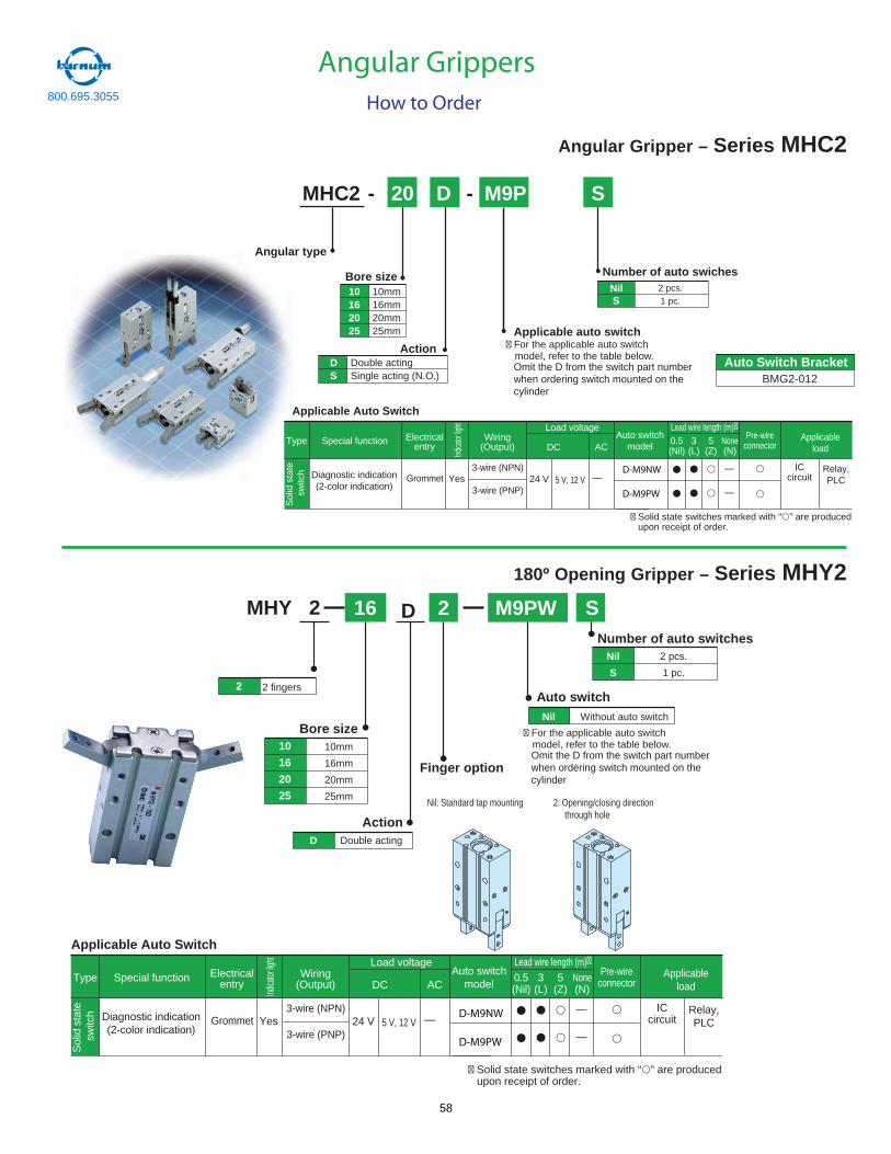
• Number of auto swiches
MHC2 - 20 D - S
Angular type •
• Applicable auto switch
Bore size •
Action •
10162025
10mm16mm20mm25mm
DS
Double actingSingle acting (N.O.)
Angular Gripper – Series MHC2
NilS
2 pcs.1 pc.
180º Opening Gripper – Series MHY2MHY 2
2
10mm
16mm
20mm
25mm
Action
Nil
S2 fingers
Bore size10
16
20
25
D Double acting
Auto switch
Number of auto switches2 pcs.
1 pc.
Nil Without auto switch
16 2D M9PW S
Nil: Standard tap mounting
Finger option
2: Opening/closing direction through hole
Angular GrippersHow to Order
* Refer to catalog N320 and Best Pn
e
Special functionType Electricalentry
Grommet
Indica
torlig
ht
Wiring(Output)
Load voltage
ACDC0.5(Nil)
3(L)
5(Z)
Applicableload
Applicable Auto Switch
—5 V, 12 VYesDiagnostic indication(2-color indication)
3-wire (NPN)
3-wire (PNP)24 V
Relay,PLC
Auto switchmodel
Sol
idst
ate
switc
h
None(N)
Pre-wireconnector
—
—
Lead wire length (m)�
ICcircuit
� Solid state switches marked with “ ” are produced upon receipt of order.
D-M9NW
D-M9PW
* Refer to catalog N320 and Best Pn
e
Special functionType Electricalentry
Grommet
Indica
torlig
ht
Wiring(Output)
Load voltage
ACDC0.5(Nil)
3(L)
5(Z)
Applicableload
Applicable Auto Switch
—5 V, 12 VYesDiagnostic indication(2-color indication)
3-wire (NPN)
3-wire (PNP)24 V
Relay,PLC
Auto switchmodel
Sol
idst
ate
switc
h
None(N)
Pre-wireconnector
—
—
Lead wire length (m)�
ICcircuit
� Solid state switches marked with “ ” are produced upon receipt of order.
D-M9PW
D-M9NW
M9P
� For the applicable auto switchmodel, refer to the table below.Omit the D from the switch part numberwhen ordering switch mounted on thecylinder
� For the applicable auto switchmodel, refer to the table below.Omit the D from the switch part numberwhen ordering switch mounted on thecylinder
Auto Switch BracketBMG2-012
800.695.3055
58
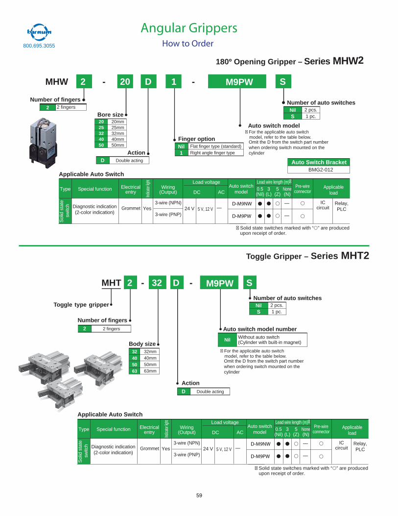
MHW 2 - 20 D 1 - S
NilS
2 pcs.1 pc.
Number of auto switches
Auto switch model
2 fingers2
Number of fingers
Bore size2025324050
20mm25mm32mm40mm50mm
ActionD Double acting
Finger optionNil1
Flat finger type (standard)Right angle finger type
180º Opening Gripper – Series MHW2
Toggle Gripper – Series MHT2
Toggle type gripper
MHT 2 - 32 D - S
Number of fingers2 2 fingers
Body size32405063
32mm40mm50mm63mm
ActionD Double acting
Nil Without auto switch(Cylinder with built-in magnet)
Auto switch model number
NilS
2 pcs.1 pc.
Number of auto switches
Angular GrippersHow to Order
* Refer to catalog N320 and Best Pn
e
Special functionType Electricalentry
Grommet
Indica
torlig
ht
Wiring(Output)
Load voltage
ACDC0.5(Nil)
3(L)
5(Z)
Applicableload
Applicable Auto Switch
—5 V, 12 VYesDiagnostic indication(2-color indication)
3-wire (NPN)
3-wire (PNP)24 V
Relay,PLC
Auto switchmodel
Sol
idst
ate
switc
h
None(N)
Pre-wireconnector
—
—
Lead wire length (m)�
ICcircuit
� Solid state switches marked with “ ” are produced upon receipt of order.
D-M9NW
D-M9PW
* Refer to catalog N320 and Best Pn
e
Special functionType Electricalentry
Grommet
Indica
torlig
ht
Wiring(Output)
Load voltage
ACDC0.5(Nil)
3(L)
5(Z)
Applicableload
Applicable Auto Switch
—5 V, 12 VYesDiagnostic indication(2-color indication)
3-wire (NPN)
3-wire (PNP)24 V
Relay,PLC
Auto switchmodel
Sol
idst
ate
switc
h
None(N)
Pre-wireconnector
—
—
Lead wire length (m)�
ICcircuit
� Solid state switches marked with “ ” are produced upon receipt of order.
D-M9NW
D-M9PW
800.695.3055
� For the applicable auto switchmodel, refer to the table below.Omit the D from the switch part numberwhen ordering switch mounted on thecylinder
M9PW
M9PW
� For the applicable auto switchmodel, refer to the table below.Omit the D from the switch part numberwhen ordering switch mounted on thecylinder
Auto Switch BracketS BMG2-012
59
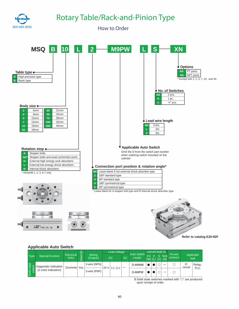
Lead wire lengthNilLZ
No. of SwitchesNilSn
Applicable Auto Switch
Table type
Body size
Options
Rotation stop
PT portsNPT ports
NilXNA
BHigh precision typeBasic type
6mm8mm
10mm12mm15mm18mm
12371020
2 pcs.1 pc."n" pcs.
0.5m3m5m
* Except size 1, 2, 3, 7, 10, and 20.
AAE*HLR
Stopper boltsStopper bolts and axial connection portsExternal high-energy sock absorbersExternal low-energy shock absorbersInternal shock absorbers
Connection port position & rotation angle*
* Leave blank for A stopper bolt type and R internal shock absorber type.
MSQ B 10 L
* MSQA/B 1, 2, 3, & 7 only.
XNS2 M9PW
Leave blank if not external shock absorber type180º standard type90º standard type180º symmetrical type90º symmetrical type
Nil2345
L
21mm25mm28mm32mm40mm
305070100200
Refer to catalog E20-92F
Rotary Table/Rack-and-Pinion TypeHow to Order
Omit the D from the switch part numberwhen ordering switch mounted on thecylinder
Special functionType Electricalentry
Grommet
Indica
torlig
ht
Wiring(Output)
Load voltage
ACDC0.5(Nil)
3(L)
5(Z)
Applicableload
Applicable Auto Switch
—5 V, 12 VYesDiagnostic indication(2-color indication)
3-wire (NPN)
3-wire (PNP)24 V
Relay,PLC
Auto switchmodel
Sol
idst
ate
switc
h
None(N)
Pre-wireconnector
—
—
Lead wire length (m)�
ICcircuit
� Solid state switches marked with “ ” are produced upon receipt of order.
D-M9NW
D-M9PW
800.695.3055
60
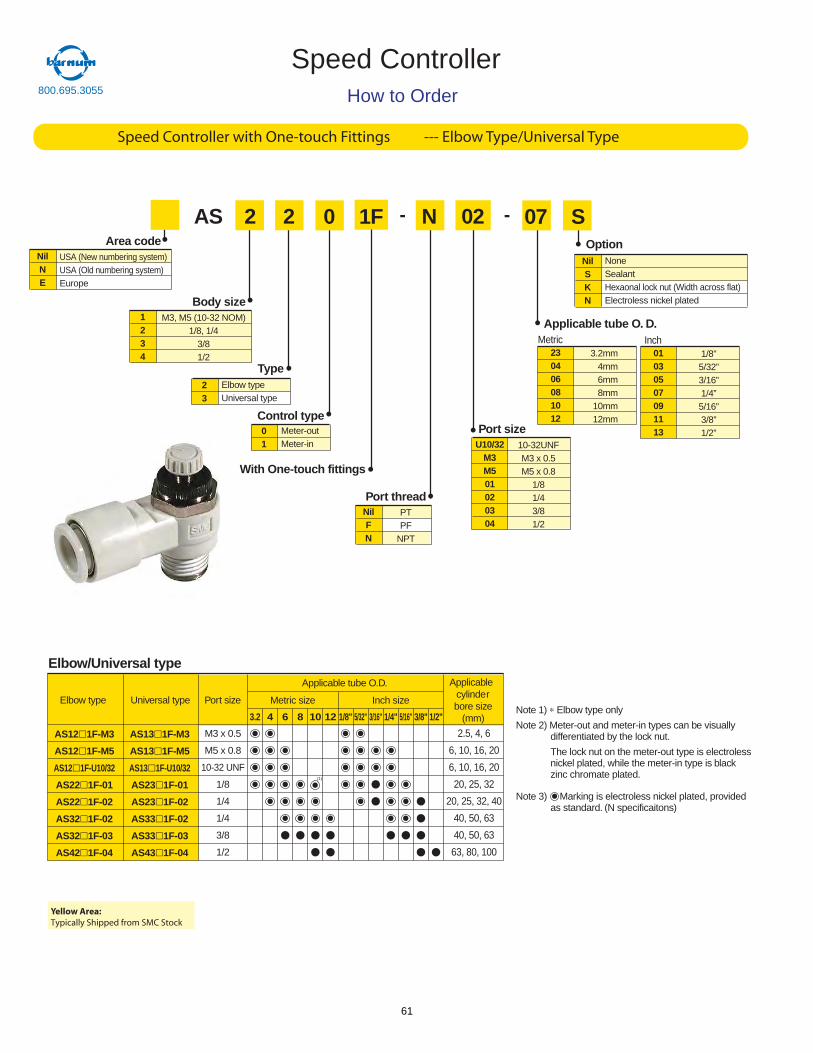
AS 2 2 - N 02 - S
Body size1234
M3, M5 (10-32 NOM)1/8, 1/4
3/81/2
Type23
Elbow typeUniversal type
0
Control type01
Meter-outMeter-in
Port threadNilFN
PTPF
NPT
Port sizeU10/32
M3M501020304
10-32UNFM3 x 0.5M5 x 0.8
1/81/43/81/2
OptionNilSKN
NoneSealantHexaonal lock nut (Width across flat)Electroless nickel plated
1F 07
Applicable tube O. D.
With One-touch fittings
230406081012
3.2mm4mm6mm8mm
10mm12mm
Metric01030507091113
1/8”5/32”3/16”1/4”5/16”3/8”1/2”
Inch
Elbow/Universal type
Elbow type
AS12 1F-M3
AS12 1F-M5
AS12 1F-U10/32
AS22 1F-01
AS22 1F-02
AS32 1F-02
AS32 1F-03
AS42 1F-04
Universal type Port size
Applicable tube O.D. Applicablecylinderbore size
(mm)
Metric size
(1)
Inch size
M3 x 0.5
M5 x 0.8
10-32 UNF
1/8
1/4
1/4
3/8
1/2
2.5, 4, 6
6, 10, 16, 20
6, 10, 16, 20
20, 25, 32
20, 25, 32, 40
40, 50, 63
40, 50, 63
63, 80, 100
AS13 1F-M3
AS13 1F-M5
AS13 1F-U10/32
AS23 1F-01
AS23 1F-02
AS33 1F-02
AS33 1F-03
AS43 1F-04
3.2 4 6 8 10 12 1/8" 5/32" 3/16" 1/4" 5/16" 3/8" 1/2"Note 1) ∗ Elbow type only
Note 2) Meter-out and meter-in types can be visuallydifferentiated by the lock nut.
The lock nut on the meter-out type is electrolessnickel plated, while the meter-in type is blackzinc chromate plated.
Note 3) Marking is electroless nickel plated, providedas standard. (N specificaitons)
Area codeNilNE
USA (New numbering system)USA (Old numbering system)Europe
How to Order
Speed Controller with One-touch Fittings --- Elbow Type/Universal Type
Speed Controller800.695.3055
Yellow Area:Typically Shipped from SMC Stock
61
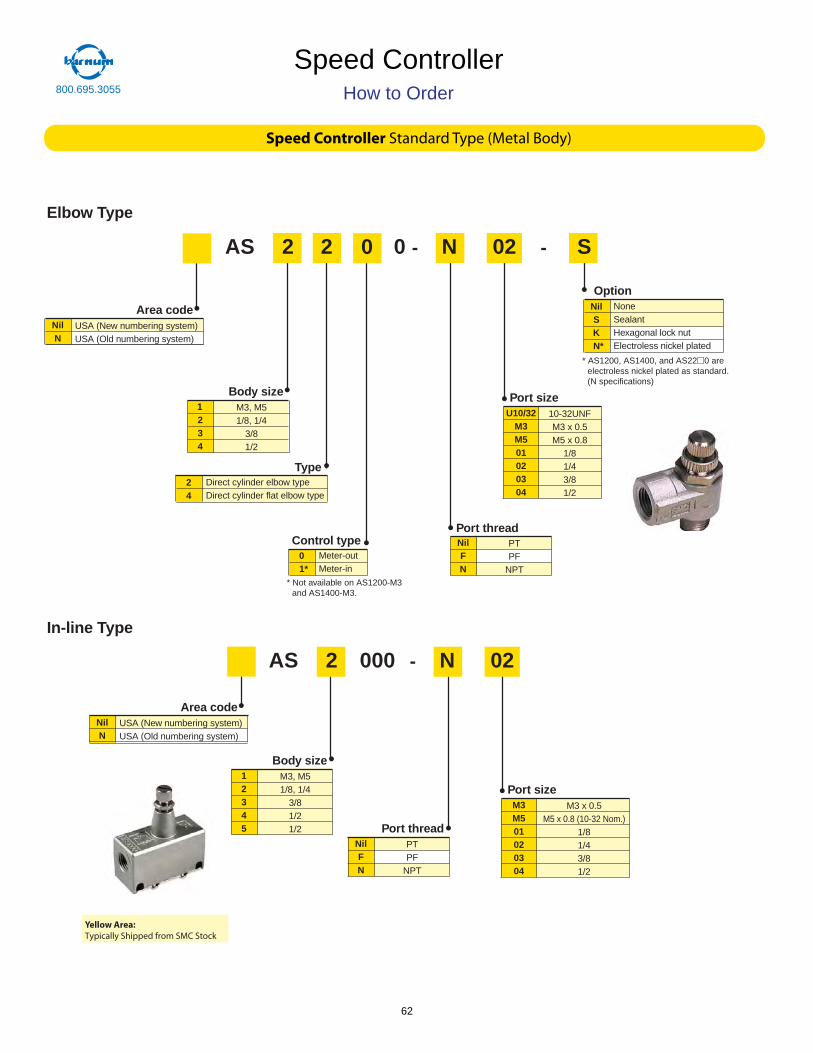
AS 2 2 0 - N 02 - S
Body size
234
M3, M51/8, 1/4
3/81/2
Type24
Direct cylinder elbow typeDirect cylinder flat elbow type
0
Control type01*
Meter-outMeter-in
* Not available on AS1200-M3 and AS1400-M3.
Port threadNilFN
PTPF
NPT
Port sizeU10/32
M3M501020304
10-32UNFM3 x 0.5M5 x 0.8
1/81/43/81/2
OptionNilSKN*
NoneSealantHexagonal lock nutElectroless nickel plated
* AS1200, AS1400, and AS22 0 are electroless nickel plated as standard.(N specifications)
Area codeNilN
USA (New numbering system)USA (Old numbering system)
AS 2 000 - N 02
Body size12345
M3, M51/8, 1/4
3/81/21/2 Port thread
NilFN
PTPF
NPT
Port sizeM3M501020304
M3 x 0.5M5 x 0.8 (10-32 Nom.)
1/81/43/81/2
Area codeNilN
USA (New numbering system)USA (Old numbering system)
In-line Type
Elbow Type
Speed Controller Standard Type (Metal Body)
1
Speed ControllerHow to Order800.695.3055
Yellow Area:Typically Shipped from SMC Stock
62
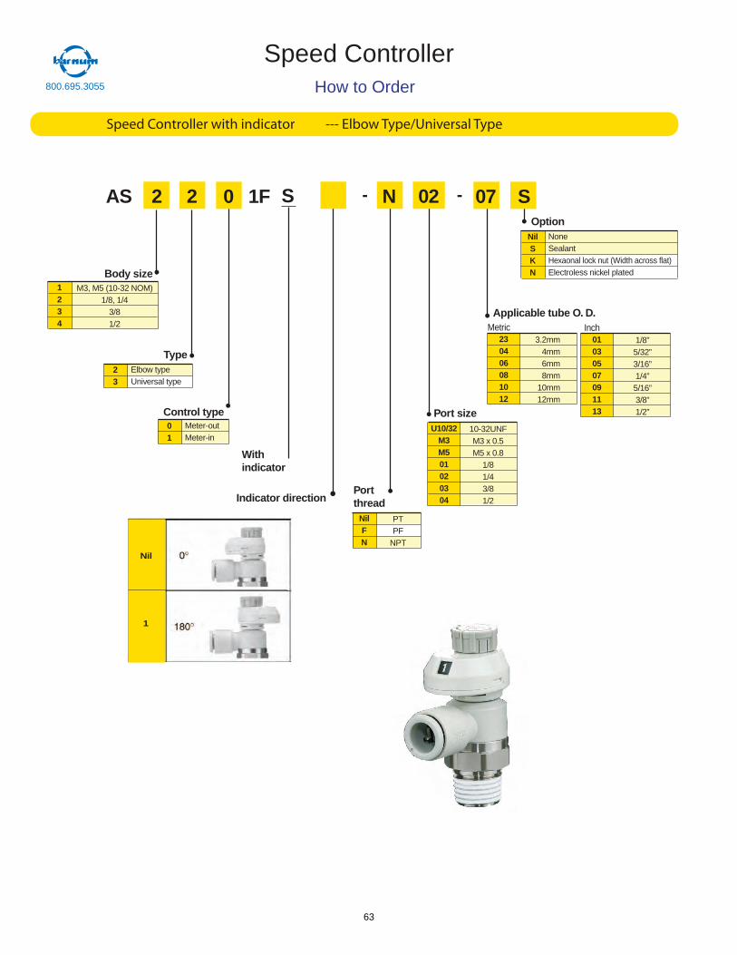
AS 2 2 - N 02 - S
Body size1234
M3, M5 (10-32 NOM)1/8, 1/4
3/81/2
Type23
Elbow typeUniversal type
0
Control type01
Meter-outMeter-in
Portthread
NilFN
PTPF
NPT
Port sizeU10/32
M3M501020304
10-32UNFM3 x 0.5M5 x 0.8
1/81/43/81/2
OptionNilSKN
NoneSealantHexaonal lock nut (Width across flat)Electroless nickel plated
1F 07
Applicable tube O. D.
230406081012
3.2mm4mm6mm8mm
10mm12mm
Metric01030507091113
1/8”5/32”3/16”1/4”5/16”3/8”1/2”
Inch
How to Order
Speed Controller with indicator --- Elbow Type/Universal Type
Speed Controller
S
Withindicator
Nil
1
Indicator direction
800.695.3055
63
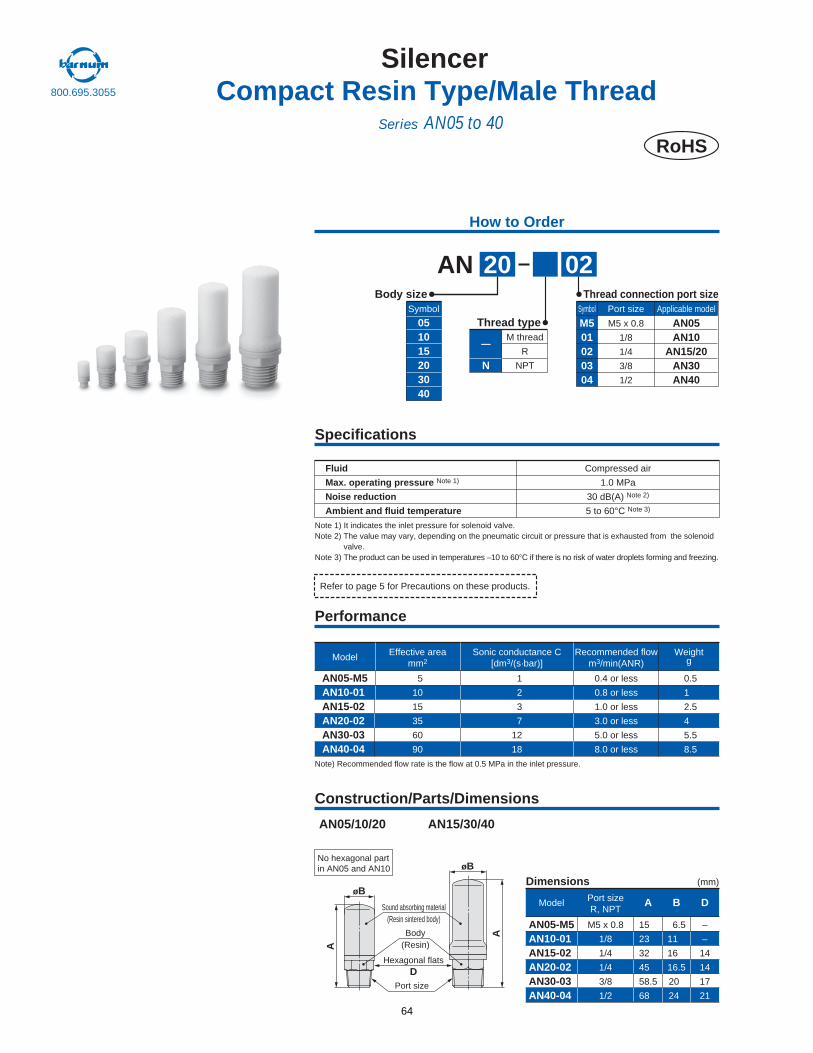
02AN 20Body size
051015203040
Symbol
Thread type M501020304
Symbol Port size
M5 x 0.8
1/8
1/4
3/8
1/2
Applicable model
AN05AN10
AN15/20AN30AN40
Thread connection port size
Note) Recommended flow rate is the flow at 0.5 MPa in the inlet pressure.
Model
AN05-M5AN10-01AN15-02AN20-02AN30-03AN40-04
Sonic conductance C[dm3/(s·bar)]
1
2
3
7
12
18
Effective areamm2
5
10
15
35
60
90
Recommended flowm3/min(ANR)
0.4 or less
0.8 or less
1.0 or less
3.0 or less
5.0 or less
8.0 or less
0.5
1
2.5
4
5.5
8.5
Weightg
No hexagonal part in AN05 and AN10
AN05/10/20 AN15/30/40
A
A
øB
øB
Sound absorbing material(Resin sintered body)
Body(Resin)
Port size
Hexagonal flatsD
Construction/Parts/Dimensions
Performance
Specifications
Note 1) It indicates the inlet pressure for solenoid valve.Note 2) The value may vary, depending on the pneumatic circuit or pressure that is exhausted from the solenoid
valve.Note 3) The product can be used in temperatures –10 to 60°C if there is no risk of water droplets forming and freezing.
Fluid
Max. operating pressure Note 1)
Noise reduction
Ambient and fluid temperature
Compressed air
1.0 MPa
30 dB(A) Note 2)
5 to 60°C Note 3)
Refer to page 5 for Precautions on these products.
—
N
M thread
R
NPT
Model
AN05-M5AN10-01AN15-02AN20-02AN30-03AN40-04
Dimensions (mm)
A
15
23
32
45
58.5
68
M5 x 0.8
1/8
1/4
1/4
3/8
1/2
B
6.5
11
16
16.5
20
24
D
–
–
14
14
17
21
How to Order
SilencerCompact Resin Type/Male Thread
Series AN05 to 40RoHS
Port sizeR, NPT
800.695.3055
64
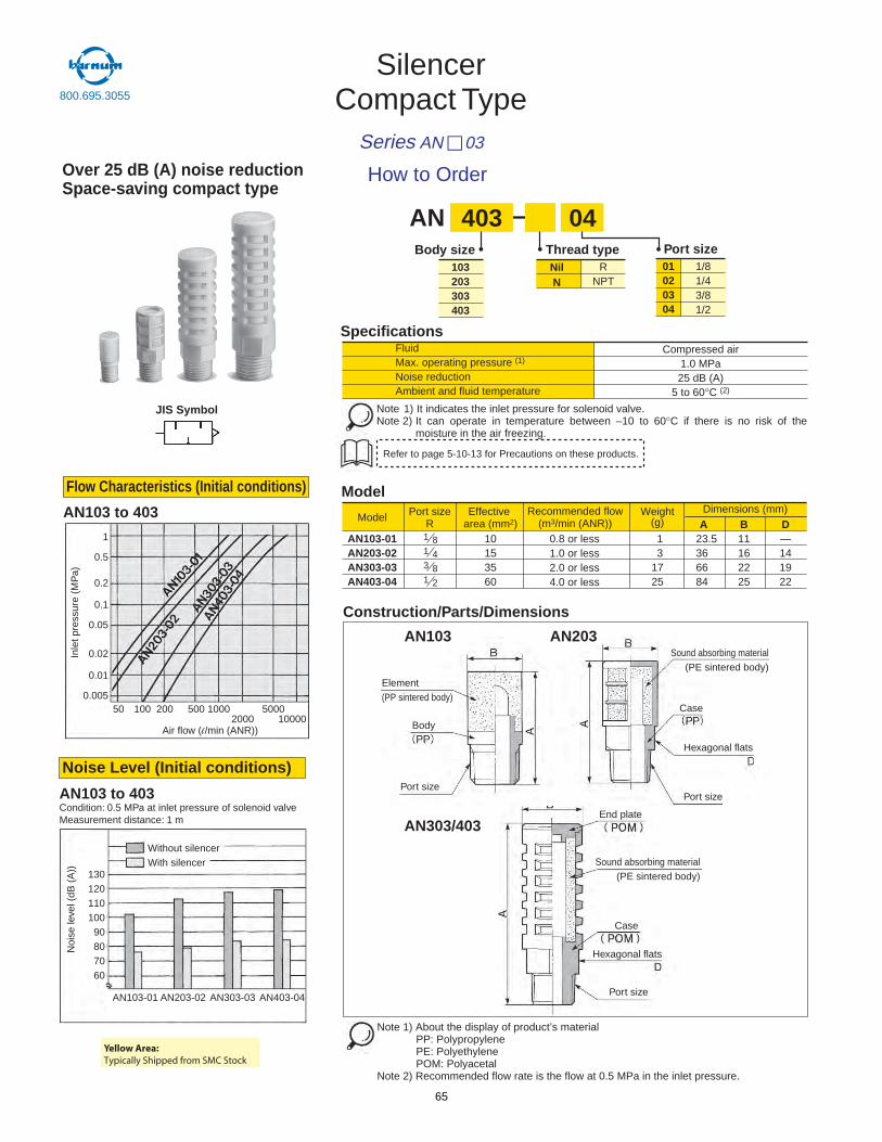
SilencerCompact Type
Series AN 03
Over 25 dB (A) noise reductionSpace-saving compact type
Thread typeBody sizeR
NPTNilN
103203303403
1/81/43/81/2
01020304
Port size
AN 403 04
Model Port sizeR
Recommended flow(m3/min (ANR))
Weight(g)
AN103-01 0.8 or less1.0 or less2.0 or less4.0 or less
1 23.5 11 —3 36 16 14
17 66 22 19
A B DDimensions (mm)
1 8
AN203-02 1 4
AN303-03 3 8
25 84 25 22AN403-04
Effectivearea (mm2)
101535601 2
Model
JIS Symbol
AN103 to 403Condition: 0.5 MPa at inlet pressure of solenoid valveMeasurement distance: 1 m
Noise Level (Initial conditions)
AN103 to 403
Construction/Parts/Dimensions
AN303/403
AN203AN103
SpecificationsCompressed air
1.0 MPa25 dB (A)
5 to 60°C (2)
Max. operating pressure (1)Fluid
Noise reductionAmbient and fluid temperature
Refer to page 5-10-13 for Precautions on these products.
Note 1) It indicates the inlet pressure for solenoid valve. Note 2) It can operate in temperature between –10 to 60°C if there is no risk of the
moisture in the air freezing.
How to Order
Note 1) About the display of product’s materialPP: PolypropylenePE: PolyethylenePOM: Polyacetal
Note 2) Recommended flow rate is the flow at 0.5 MPa in the inlet pressure.
Element(PP sintered body)
1
0.5
0.2
0.1
0.05
0.02
0.01
0.00550 100 200 500 1000
20005000
10000
13012011010090807060
AN103-01 AN203-02 AN303-03 AN403-04
Flow Characteristics (Initial conditions)
End plate
Sound absorbing material(PE sintered body)
Sound absorbing material(PE sintered body)
Case
Case
Hexagonal flats
Hexagonal flats
Port size
Port sizePort size
BodyAir flow (l /min (ANR))
Without silencerWith silencer
Inle
t pre
ssur
e (M
Pa)
Noi
se le
vel (
dB (
A))
800.695.3055
Yellow Area:Typically Shipped from SMC Stock
65
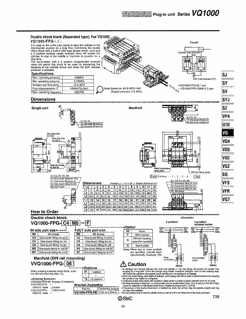
66
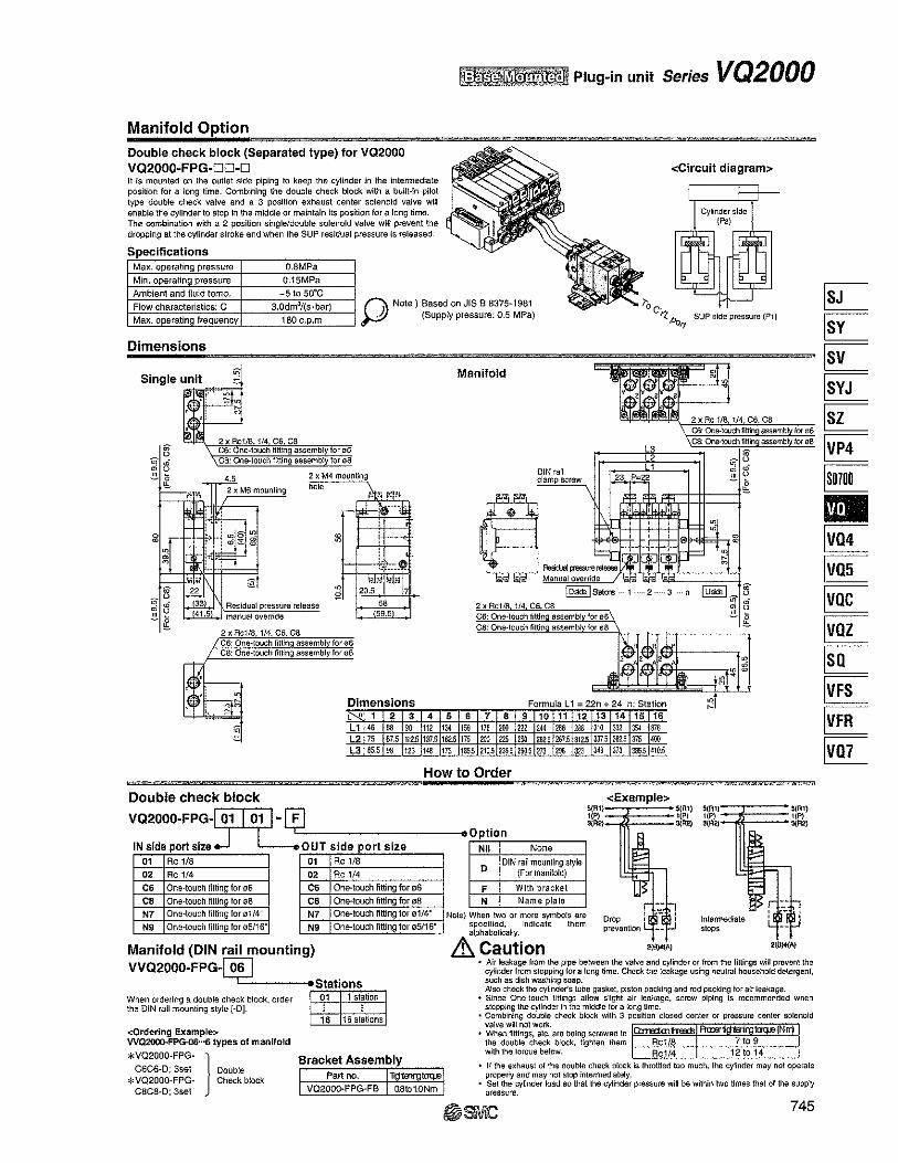
67
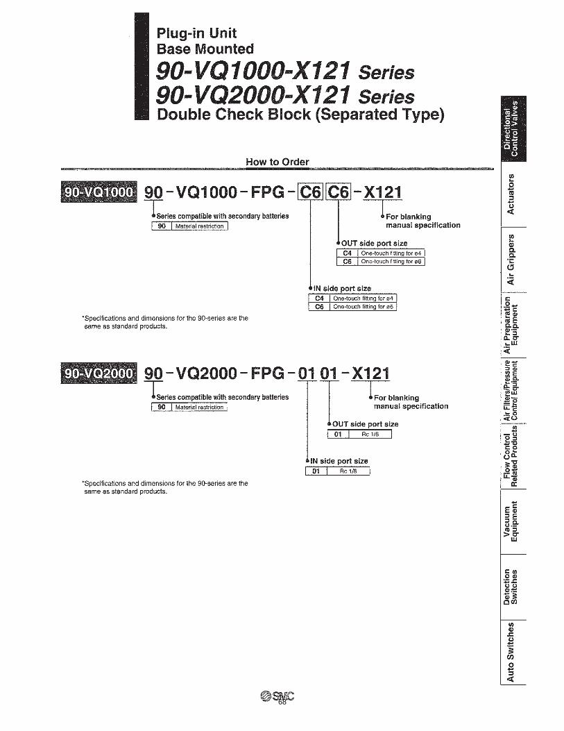
68
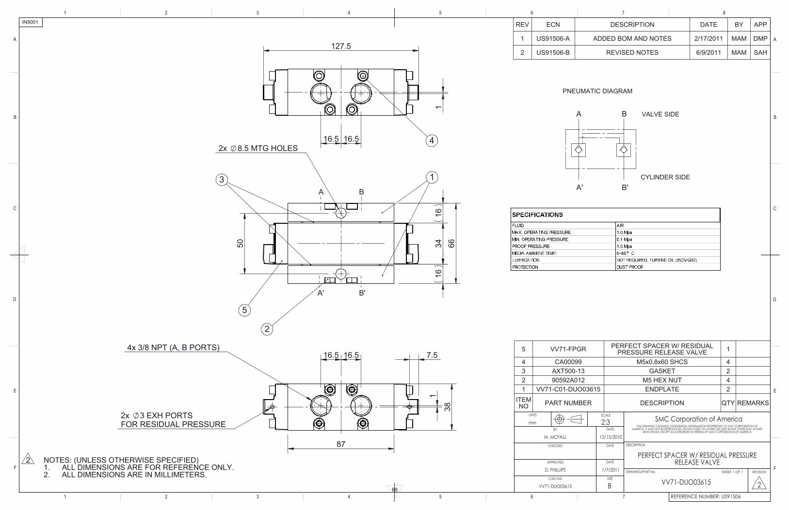
50
1634
1666
2x 8.5 MTG HOLES
A B
A' B'
5
3 1
2
127.5
16.516.5
1
4
7.516.5 16.5
8738
1
4x 3/8 NPT (A, B PORTS)
2x 3 EXH PORTS FOR RESIDUAL PRESSURE
B'A'
BA
CYLINDER SIDE
VALVE SIDE
PNEUMATIC DIAGRAM
NOTES: (UNLESS OTHERWISE SPECIFIED)ALL DIMENSIONS ARE FOR REFERENCE ONLY.1.ALL DIMENSIONS ARE IN MILLIMETERS.2.
2
5 VV71-FPGR PERFECT SPACER W/ RESIDUAL PRESSURE RELEASE VALVE 1
4 CA00099 M5x0.8x60 SHCS 43 AXT500-13 GASKET 22 90592A012 M5 HEX NUT 41 VV71-C01-DUO03615 ENDPLATE 2
ITEMNO PART NUMBER DESCRIPTION QTY REMARKS
REV ECN DESCRIPTION DATE BY APP
1 US91506-A ADDED BOM AND NOTES 2/17/2011 MAM DMP
2 US91506-B REVISED NOTES 6/9/2011 MAM SAH
REFERENCE NUMBER: US91506
87654321
7654321
F
E
D
A
C
B
F
A
B
E
D
C
IN9001
VV71-DUO03615
1/7/2011D. PHILLIPS
12/15/2010
2:3SCALE
BSIZE
UNITS
mmTHIS DRAWING CONTAINS CONFIDENTIAL INFORMATION PROPRIETARY TO SMC CORPORATION OF
AMERICA. IT MUST NOT BE REPRODUCED OR DISCLOSED TO OTHERS OR USED IN ANY OTHER WAY, IN PART OR IN WHOLE, EXCEPT AS AUTHORIZED IN WRITING BY SMC CORPORATION OF AMERICA.
DESCRIPTION
REVISION
2
DRAWING/PART No.
DATEBY
M. MCFALLDATECHECKED
DATEAPPROVED
CAD FILE
PERFECT SPACER W/ RESIDUAL PRESSURE RELEASE VALVE
VV71-DUO03615
SMC Corporation of America
SHEET 1 OF 1
69
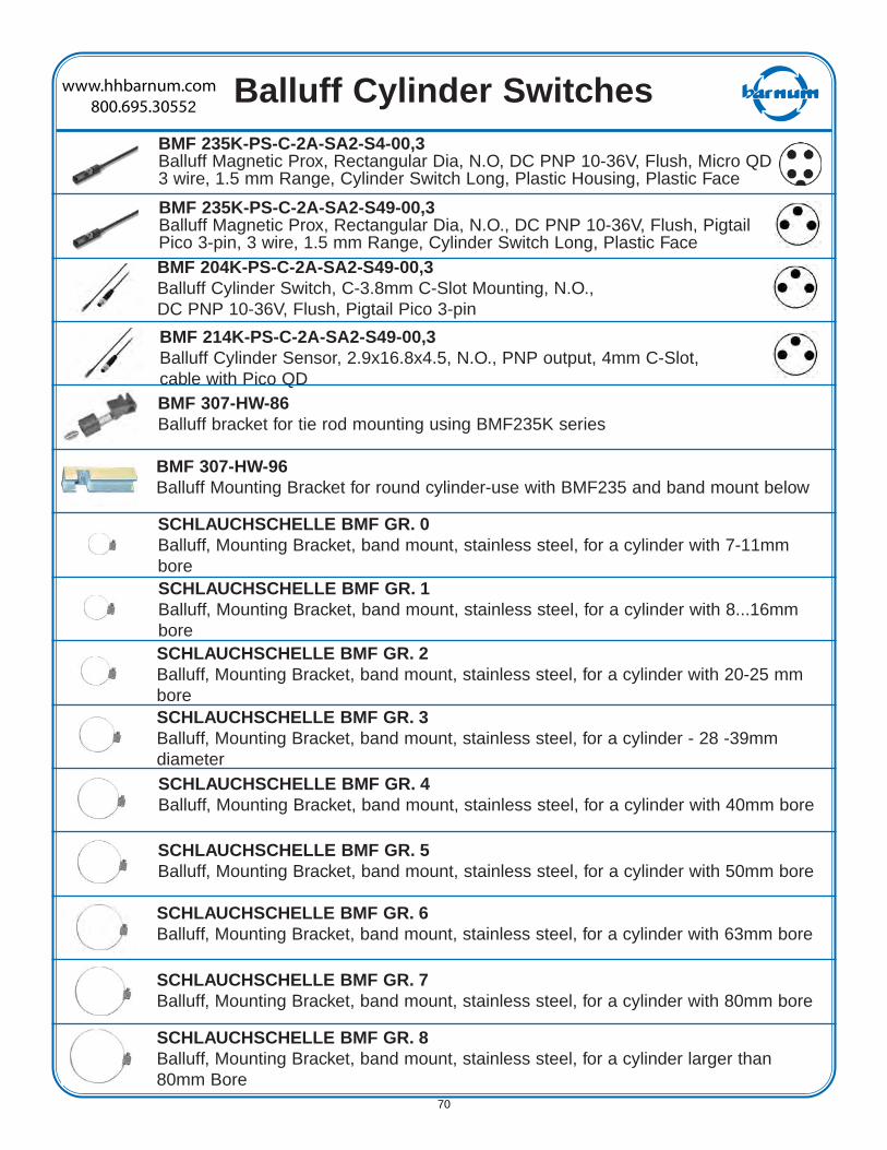
Balluff Cylinder SwitchesBMF 235K-PS-C-2A-SA2-S4-00,3Balluff Magnetic Prox, Rectangular Dia, N.O, DC PNP 10-36V, Flush, Micro QD3 wire, 1.5 mm Range, Cylinder Switch Long, Plastic Housing, Plastic Face
BMF 235K-PS-C-2A-SA2-S49-00,3Balluff Magnetic Prox, Rectangular Dia, N.O., DC PNP 10-36V, Flush, PigtailPico 3-pin, 3 wire, 1.5 mm Range, Cylinder Switch Long, Plastic Face
BMF 214K-PS-C-2A-SA2-S49-00,3Balluff Cylinder Sensor, 2.9x16.8x4.5, N.O., PNP output, 4mm C-Slot,cable with Pico QDBMF 307-HW-86Balluff bracket for tie rod mounting using BMF235K series
BMF 307-HW-96Balluff Mounting Bracket for round cylinder-use with BMF235 and band mount below
SCHLAUCHSCHELLE BMF GR. 0Balluff, Mounting Bracket, band mount, stainless steel, for a cylinder with 7-11mmboreSCHLAUCHSCHELLE BMF GR. 1Balluff, Mounting Bracket, band mount, stainless steel, for a cylinder with 8...16mmboreSCHLAUCHSCHELLE BMF GR. 2Balluff, Mounting Bracket, band mount, stainless steel, for a cylinder with 20-25 mmboreSCHLAUCHSCHELLE BMF GR. 3Balluff, Mounting Bracket, band mount, stainless steel, for a cylinder - 28 -39mmdiameterSCHLAUCHSCHELLE BMF GR. 4Balluff, Mounting Bracket, band mount, stainless steel, for a cylinder with 40mm bore
SCHLAUCHSCHELLE BMF GR. 5Balluff, Mounting Bracket, band mount, stainless steel, for a cylinder with 50mm bore
SCHLAUCHSCHELLE BMF GR. 6Balluff, Mounting Bracket, band mount, stainless steel, for a cylinder with 63mm bore
SCHLAUCHSCHELLE BMF GR. 7Balluff, Mounting Bracket, band mount, stainless steel, for a cylinder with 80mm bore
SCHLAUCHSCHELLE BMF GR. 8Balluff, Mounting Bracket, band mount, stainless steel, for a cylinder larger than80mm Bore
BMF 204K-PS-C-2A-SA2-S49-00,3Balluff Cylinder Switch, C-3.8mm C-Slot Mounting, N.O., DC PNP 10-36V, Flush, Pigtail Pico 3-pin
www.hhbarnum.com800.695.3055
70
Balluff Cylinder Switches www.hhbarnum.com800.695.3055
BMF0005 BMF 204K-PS-2A-SA95-S4-00,3Balluff Cylinder Switch, V Twin Series, C-Slot Mounting, N.O.,DC PNP 10-36V, for 3.8mm C-Slot, M12 4-Pin
BMF0006 BMF 204K-PS-C-2A-SA95-S75-00,3Balluff Cylinder Switch, V-Twin Series, C-Slot Mounting, N.O.,PNP, 10-36V for 3.8mm C-Slot, M8 4-Pin
BMF00C9 BMF 235K-PS-C-2A-SA95-S4-00,3Balluff Cylinder Switch, V Twin Series, N.O., PNP 10-36V, for T-Slots, M12 4-pin
BMF00CA BMF 235-PS-C-2A-SA95-S75-00,3Balluff Cylinder Switch, V Twin Series, N.O., PNP 10-36V, for T-Slots, M8 4-pin
BMF00A4 BMF 214K-PS-C-2A-SA95-S4-00,3Balluff Cylinder Switch, V Twin Series, C-Slot, N.O., PNP 10-30Vfor 4mm C- Slot SMC, M12 4-Pin
BMF00A5 BMF 214K-PS-C-2A-SA95-S75-00,3Balluff Cylinder Switch, V Twin Series, C-Slot, N.O., PNP 10-30V,for 4mm C-Slot SMC, M8 4-Pin
71
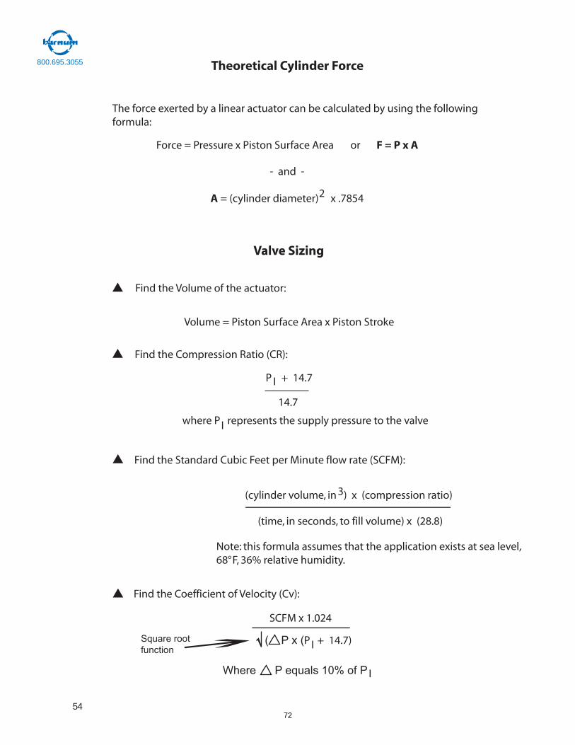
Theoretical Cylinder Force
The force exerted by a linear actuator can be calculated by using the followingformula:
Force = Pressure x Piston Surface Area or F = P x A
- and -
A = (cylinder diameter) x .78542
Valve Sizing
Find the Volume of the actuator:
Volume = Piston Surface Area x Piston Stroke
Find the Compression Ratio (CR):
P + 14.7I
14.7
where P represents the supply pressure to the valveI
Find the Standard Cubic Feet per Minute flow rate (SCFM):
(cylinder volume, in ) x (compression ratio)3
(time, in seconds, to fill volume) x (28.8)
Note: this formula assumes that the application exists at sea level,68°F, 36% relative humidity.
Find the Coefficient of Velocity (Cv):
SCFM x 1.024
( P x (P + 14.7)I
Where P equals 10% of P I
Square rootfunction
800.695.3055
572

Auto Switches
Reed Switches: A thin metal contact is drawn closed by the magnetic field of the piston magnet. Since this is a a mechanical switch it will wear out over time and is suspecptible to vibration and shock. The advantage is that they are inexpesnsive and can be used with AC voltage.
Solid State Switches: the magnetic field generated by the piston magnet causes a current flow inside the switch.Since there are no moving parts, the switch life is much longer than a reed switch and they are less prone to vibrationand shock.They are more expensive, can only be used with DC voltages and you need to know whether you need a sinking or sourcing switch.
Three wire DC sensors include one wire that provides current to the sensor, an output signalwire and a ground wire. Most electro-mechanical loads (relays, counters, solenoids etc.) can useeither a sink or source type switch provided it is wired properly.The proper sensor type must bechosen when used with solid-state loads and programmable controllers due to the fact that someof these loads must be grounded.
Wire Colors: SMC has changed the wire colors on all of our switch products. This was done toconform to European standards that are being adopted worldwide.
Positive
Negative
Output
Red
Black
White
(old colors)
Brown
Blue
Black
(new colors)
Sensor
NPN 2 Wire Sensor Wiring
Load
+24VDC
-24VDC
Blue
BlackSensor
NPN 3 Wire Sensor Wiring
Load
+24VDC
-24VDC
Blue
Brown Black
Sensor
PNP 2 Wire Sensor Wiring
Load
+24VDC
-24VDC
BlackBrown
Sensor Load
+24VDC
-24VDC
Blue
Brown Black
PNP 3 Wire Sensor Wiring
800.695.3055
5
73
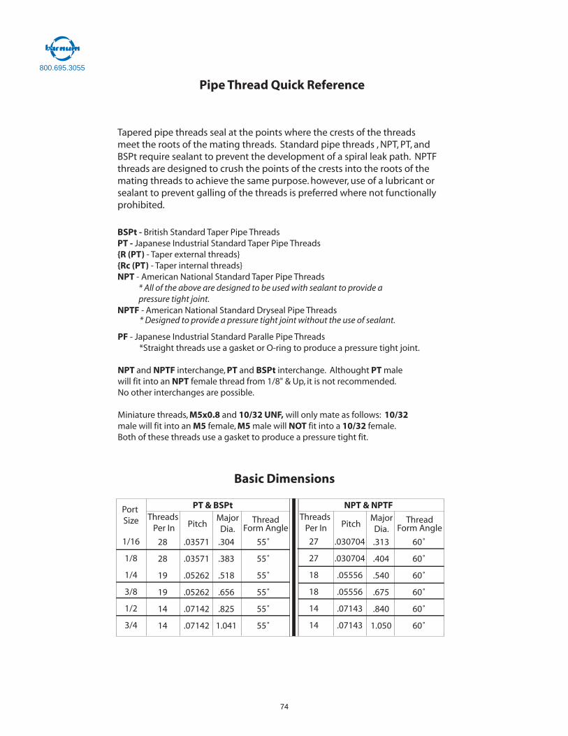
Pipe Thread Quick Reference
Tapered pipe threads seal at the points where the crests of the threadsmeet the roots of the mating threads. Standard pipe threads , NPT, PT, andBSPt require sealant to prevent the development of a spiral leak path. NPTFthreads are designed to crush the points of the crests into the roots of themating threads to achieve the same purpose. however, use of a lubricant orsealant to prevent galling of the threads is preferred where not functionally prohibited.
BSPt - British Standard Taper Pipe ThreadsPT - Japanese Industrial Standard Taper Pipe Threads{R (PT) - Taper external threads}{Rc (PT) - Taper internal threads}NPT - American National Standard Taper Pipe Threads
* All of the above are designed to be used with sealant to provide apressure tight joint.
NPTF - American National Standard Dryseal Pipe Threads* Designed to provide a pressure tight joint without the use of sealant.
PF - Japanese Industrial Standard Paralle Pipe Threads *Straight threads use a gasket or O-ring to produce a pressure tight joint.
NPT and NPTF interchange, PT and BSPt interchange. Althought PT male will fit into an NPT female thread from 1/8" & Up, it is not recommended.No other interchanges are possible.
Miniature threads, M5x0.8 and 10/32 UNF, will only mate as follows: 10/32male will fit into an M5 female, M5 male will NOT fit into a 10/32 female.Both of these threads use a gasket to produce a pressure tight fit.
Basic Dimensions
Port Size
PT & BSPtThreads
Per In PitchMajorDia.
ThreadForm Angle
1/16
1/8
1/4
3/8
1/2
3/4
28
28
19
19
14
14
.03571
.03571
.05262
.05262
.07142
.07142
.304
.383
.518
.656
.825
1.041
55˚
55˚
55˚
55˚
55˚
55˚
NPT & NPTFThreads
Per In PitchMajorDia.
ThreadForm Angle
.030704
.030704
.05556
.05556
.07143
.07143
.313
.404
.540
.675
.840
1.050
60˚
60˚
60˚
60˚
60˚
60˚
27
27
18
18
14
14
800.695.3055
74

* NE Ohio only
2/14
75
Michigan Ohio Windsor, CanadaIndiana
Controls for Factory Automation
ATC - timers and counters
Balluff - proximity, photoelectric and cylinder sensors,industrial RFID, remote power systems, linear position transducers, connectivity products
Banner - photoelectric and vision sensors, safety light curtains, interlocks, cycle start buttons, controllers,EZ-lights, stacklights, LED lighting, wireless products
Brady - labeling and identification systems
Cablofil - cable tray
Carlo Gavazzi - SSRs and sensors
Dalsa - industrial machine vision systems
eWON - industrial VPN routers for remote access to machinenetworks
Exlar - electric linear actuators, servo motors
+GF+ Signet - flow and analytical sensors
Hirschmann - industrial Ethernet and networking products
Iboco - plastic wiring duct, cable ties
ICG - levelers, handles, knobs, wheels
Ilme - multi-pole rectangular connectors
Indusoft - automation and process control software
Jenatec - linear rails and carriages, ball screws, spindles, linear actuators
JVL - integrated servo motors, smart motors
Kabelschlepp - cable and hose carriers
Larco - safety mats
Lenze/AC Tech - drives, servo controllers and motors
Lumberg - molded watertight connectors, distribution boxes,industrial networks, ethernet connectors
Lutze - control cable, power supplies, cable fittings
Magswitch - magnetic grippers and clamps
Mencom - panel interface connectors, cable glands
Mersen - fuses, fuse blocks, disconnects, power distribution blocks
Metaphase - specialty vision lighting
Murrplastik - flexible conduit, cable entry systems, cable drag chain, ACS plotter style labeling system
NSK - ball screws, slides and linear actuators
Nematron - industrial computers, HMIs, remote I/O
Niedax - cable tray, metal wire duct, ladder tray
Patlite - stacklights, horns, LED lighting
Pro-face - HMIs, operator interface with PLC
Recognition Robotics - vision software and sensors thatmake complex solutions simple
Red Lion - data acquisition, data logging, message displays, panel meters, counters, HMIs, protocol converters, temperature controllers
Rittal - enclosures and air conditioners
RTD Company - RTDs, thermocouples, transmitters
Schmersal/Elan - safety interlocks and relays
SMC - pneumatic valves, actuators, air preparation,fittings/tubing, vacuum products and grippers
SoftNoze USA Inc. - sensor mounting and protection products
Swivel-Link - mounting hardware for vision cameras,lighting, sensors and more
T-Slots - aluminum extrusion guarding and framing
VIPA - IP20 I/O modules, profibus connectors withdiagnostics
VSE - positive displacement flow meters
Weidmuller - terminal blocks, power supplies, cable entry systems, ethernet products, circuit protection, wiring ferrules, wireless systems
hhbarnum.comH.H. Barnum Company
7915 Lochlin Drive, Brighton MI 48116800.695.3055
76
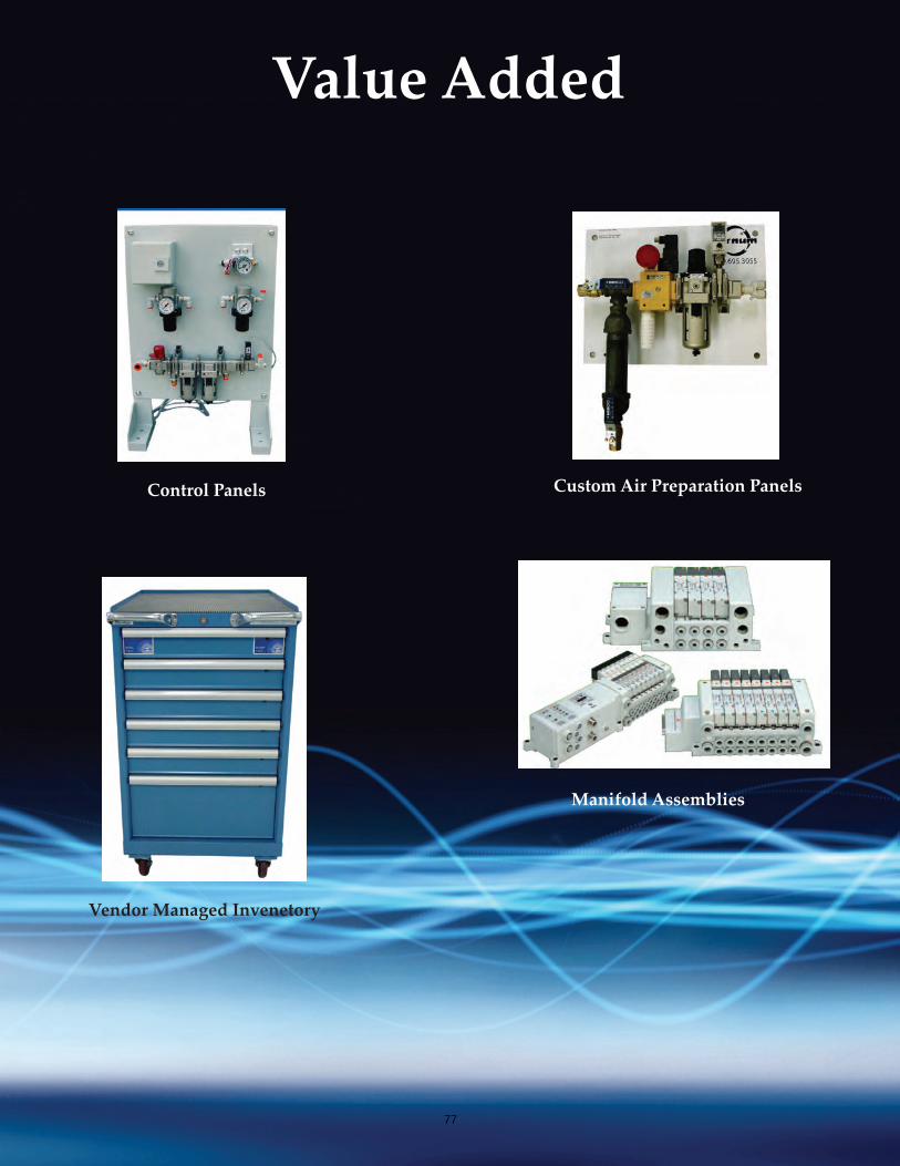
Value Added
Control Panels Custom Air Preparation Panels
Vendor Managed Invenetory
Manifold Assemblies
77