Embed Size (px)
DESCRIPTION
SMD9200 Satellite Modulator User Guide
Citation preview

September 2012 Form 8067 Revision 2.3
DVB-S2 Satellite Modulator
User Guide
User Guide
Page 2 (69)
Disclaimer Harmonic reserves the right to alter the equipment specifications and descriptions in this publication without prior notice. No part ofthis publication shall be deemed to be part of any contract or warranty unless specifically incorporated by reference into suchcontract or warranty. The information contained herein is merely descriptive in nature, and does not constitute a binding offer forsale of the product described herein. Harmonic assumes no responsibility or liability arising from the use of the products describedherein, except as expressly agreed to in writing by Harmonic. The use and purchase of this product do not convey a license underany patent rights, copyrights, trademark rights, or any intellectual property rights of Harmonic. Nothing hereunder constitutes arepresentation or warranty that using any products in the manner described herein will not infringe any patents of third parties. Trademark Acknowledgments Harmonic and all Harmonic product names are trademarks of Harmonic Inc. All other trademarks are the property of their respectiveowners. ©2012 Harmonic Inc. All rights reserved.
User Guide
Page 3 (69)
Revision History
Date Version Description Author
08/01/2012 0.1 Initial Draft GJL

User Guide
Page 4 (69)
Safety Instructions
• Read these instructions • Keep these instructions • Heed all warnings • Follow all instructions • Do not use this apparatus near water • Clean only with dry cloth • Do not block any ventilation openings. Install in accordance with the
manufacturer’s instructions • Do not install near any heat sources such as radiators, heat registers, stoves, or
other apparatus (including amplifiers) that produce heat • Do not defeat the safety purpose of the polarized or grounding-type plug. A
polarized plughas two blades with one wider than the other. A grounding type plug has two blades and athird grounding prong. The wide blade or the third prong is provided for your safety. If theprovided plug does not fit into your outlet, consult an electrician for replacement of theobsolete outlet.
• Protect the power cord from being walked on or pinched particularly at plugs, conveniencereceptacles, and the point where they exit from the apparatus.
• Only use attachments/accessories specified by the manufacturer. • Unplug this apparatus during lightning storms or when unused for long periods of
time. • Refer all servicing to qualified service personnel. Servicing is required when the
apparatushas been damaged in any way, such as power-supply cord or plug is damaged, liquid hasbeen spilled or objects have fallen into the apparatus, the apparatus has been exposed to rainor moisture, does not operate normally, or has been dropped.
• Do not expose this apparatus to dripping or splashing and ensure that no objectsfilled with liquids, such as vases, are placed on the apparatus.
• To completely disconnect this apparatus from the AC Mains, disconnect the powersupply cord plug from the AC receptacle.
• The mains plug of the power supply cord shall remain readily operable. • Damage Requiring Service: Unplug this product from the wall outlet and
referservicing to qualified service personnel under the following conditions: • When the power-supply cord or plug is damaged. • If liquid has been spilled, or objects have fallen into the product. • If the product has been exposed to rain or water. • If the product does not operate normally by following the operating instructions.
Adjust only those controls that are covered by the operating instructions as an improper adjustment of the controls may result in damage and will often require extensive work by a qualified technician to restore the product to its normal operation.
• If the product has been dropped or damaged in any way. • The product exhibits a distinct change in performance.

User Guide
Page 5 (69)
SAFETY PRECAUTIONS There is always a danger present when using electronic equipment. Unexpected high voltages can be present at unusual locations in defective equipment and signal distribution systems. Become familiar with the equipment that you are working with and observe the following safety precautions.
• Every precaution has been taken in the design of your Satellite Modulator to insure that it is as safe as possible. However, safe operation depends on you the operator.
• Always be sure your equipment is in good working order. Ensure that all points of connection are secure to the chassis, and that protective covers are in place and secured with fasteners.
• Never work alone when working in hazardous conditions. Always have another person close by in case of an accident.
• Always refer to the manual for safe operation. If you have a question about the application or operation call Sencore for assistance.
• WARNING – To reduce the risk of fire or electrical shock never allow your equipment to be exposed to water, rain or high moisture environments. If exposed to a liquid, remove power safely (at the breaker) and send your equipment to be serviced by a qualified technician.
• To reduce the risk of shock the SMD 9200 must be connected to a mains socket outlet with a protective earthing connection.
• For the SMD 9200 the mains plug is the main disconnect and should remain readily accessible and operable at all times.
• The SMD 9200 is equipped with an internal system battery. The SMD must be sent if to Sencore service for replacement
CAUTION – Danger of explosion if battery is incorrectly replaced. Replace only with the same or equivalent type.
FCC Class A Information The SMD 9200 has been tested and found to comply with the limits for a Class A digital device, pursuant to Part 15 of the FCC Rules. These limits are designed to provide reasonable protection against harmful interference when the equipment is operated in a commercial environment. This equipment generates, uses, and can radiate radio frequency energy and, if not installed and used in accordance with the instructions, may cause harmful interference to radio communications. Operation of this equipment in a residential area is likely to cause harmful interference in which case the user will be required to correct the interference at his or her own expense.
Shielded cables must be used with this unit to ensure compliance with the Class A FCC limits.
Warning: Changes or modifications to this unit not expressly approved by the party responsible for compliance could void the user’s authority to operate the equipment.
User Guide
Page 6 (69)
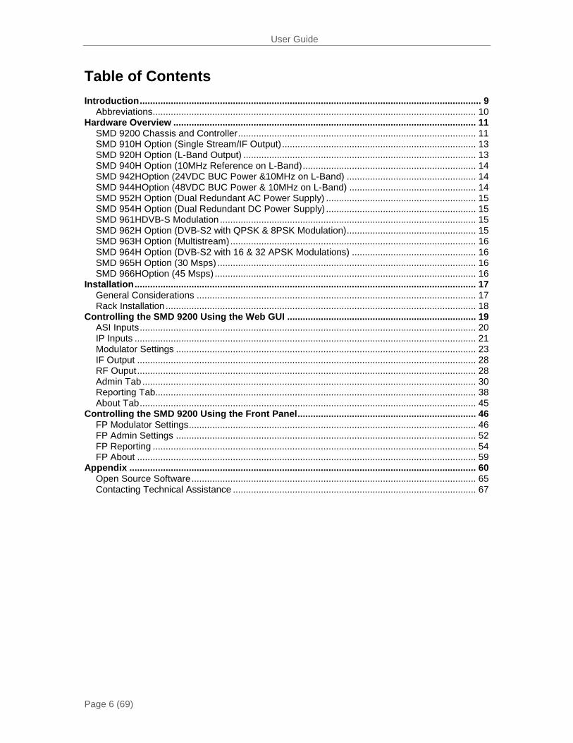
Table of Contents Introduction .................................................................................................................................... 9
Abbreviations............................................................................................................................. 10 Hardware Overview ..................................................................................................................... 11
SMD 9200 Chassis and Controller ............................................................................................ 11 SMD 910H Option (Single Stream/IF Output) ........................................................................... 13 SMD 920H Option (L-Band Output) .......................................................................................... 13 SMD 940H Option (10MHz Reference on L-Band) ................................................................... 14 SMD 942HOption (24VDC BUC Power &10MHz on L-Band) .................................................. 14 SMD 944HOption (48VDC BUC Power & 10MHz on L-Band) ................................................. 14 SMD 952H Option (Dual Redundant AC Power Supply) .......................................................... 15 SMD 954H Option (Dual Redundant DC Power Supply) .......................................................... 15 SMD 961HDVB-S Modulation ................................................................................................... 15 SMD 962H Option (DVB-S2 with QPSK & 8PSK Modulation) .................................................. 15 SMD 963H Option (Multistream) ............................................................................................... 16 SMD 964H Option (DVB-S2 with 16 & 32 APSK Modulations) ................................................ 16 SMD 965H Option (30 Msps) .................................................................................................... 16 SMD 966HOption (45 Msps) ..................................................................................................... 16
Installation .................................................................................................................................... 17 General Considerations ............................................................................................................ 17 Rack Installation ........................................................................................................................ 18
Controlling the SMD 9200 Using the Web GUI ......................................................................... 19 ASI Inputs .................................................................................................................................. 20 IP Inputs .................................................................................................................................... 21 Modulator Settings .................................................................................................................... 23 IF Output ................................................................................................................................... 28 RF Ouput ................................................................................................................................... 28 Admin Tab ................................................................................................................................. 30 Reporting Tab............................................................................................................................ 38 About Tab .................................................................................................................................. 45
Controlling the SMD 9200 Using the Front Panel ..................................................................... 46 FP Modulator Settings ............................................................................................................... 46 FP Admin Settings .................................................................................................................... 52 FP Reporting ............................................................................................................................. 54 FP About ................................................................................................................................... 59
Appendix ...................................................................................................................................... 60 Open Source Software .............................................................................................................. 65 Contacting Technical Assistance .............................................................................................. 67
User Guide
Page 7 (69)
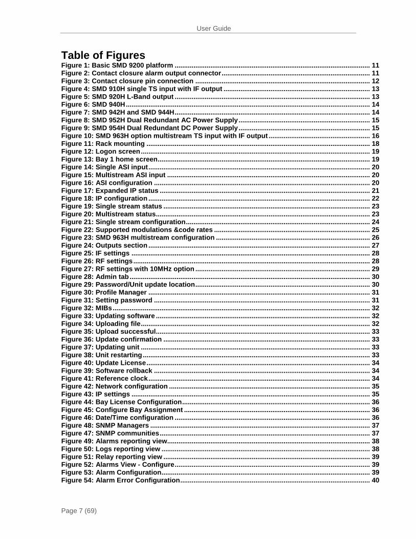
Table of Figures Figure 1: Basic SMD 9200 platform ........................................................................................................ 11 Figure 2: Contact closure alarm output connector ............................................................................... 11 Figure 3: Contact closure pin connection ............................................................................................. 12 Figure 4: SMD 910H single TS input with IF output .............................................................................. 13 Figure 5: SMD 920H L-Band output ........................................................................................................ 13 Figure 6: SMD 940H .................................................................................................................................. 14 Figure 7: SMD 942H and SMD 944H ........................................................................................................ 14 Figure 8: SMD 952H Dual Redundant AC Power Supply ...................................................................... 15 Figure 9: SMD 954H Dual Redundant DC Power Supply ...................................................................... 15 Figure 10: SMD 963H option multistream TS input with IF output ...................................................... 16 Figure 11: Rack mounting ....................................................................................................................... 18 Figure 12: Logon screen .......................................................................................................................... 19 Figure 13: Bay 1 home screen ................................................................................................................. 19 Figure 14: Single ASI input ...................................................................................................................... 20 Figure 15: Multistream ASI input ............................................................................................................ 20 Figure 16: ASI configuration ................................................................................................................... 20 Figure 17: Expanded IP status ................................................................................................................ 21 Figure 18: IP configuration ...................................................................................................................... 22 Figure 19: Single stream status .............................................................................................................. 23 Figure 20: Multistream status .................................................................................................................. 23 Figure 21: Single stream configuration .................................................................................................. 24 Figure 22: Supported modulations &code rates ................................................................................... 25 Figure 23: SMD 963H multistream configuration .................................................................................. 26 Figure 24: Outputs section ...................................................................................................................... 27 Figure 25: IF settings ............................................................................................................................... 28 Figure 26: RF settings .............................................................................................................................. 28 Figure 27: RF settings with 10MHz option ............................................................................................. 29 Figure 28: Admin tab ................................................................................................................................ 30 Figure 29: Password/Unit update location ............................................................................................. 30 Figure 30: Profile Manager ...................................................................................................................... 31 Figure 31: Setting password ................................................................................................................... 31 Figure 32: MIBs ......................................................................................................................................... 32 Figure 33: Updating software .................................................................................................................. 32 Figure 34: Uploading file .......................................................................................................................... 32 Figure 35: Upload successful .................................................................................................................. 33 Figure 36: Update confirmation .............................................................................................................. 33 Figure 37: Updating unit .......................................................................................................................... 33 Figure 38: Unit restarting ......................................................................................................................... 33 Figure 40: Update License ....................................................................................................................... 34 Figure 39: Software rollback ................................................................................................................... 34 Figure 41: Reference clock ...................................................................................................................... 34 Figure 42: Network configuration ........................................................................................................... 35 Figure 43: IP settings ............................................................................................................................... 35 Figure 44: Bay License Configuration .................................................................................................... 36 Figure 45: Configure Bay Assignment ................................................................................................... 36 Figure 46: Date/Time configuration ........................................................................................................ 36 Figure 48: SNMP Managers ..................................................................................................................... 37 Figure 47: SNMP communities ................................................................................................................ 37 Figure 49: Alarms reporting view............................................................................................................ 38 Figure 50: Logs reporting view ............................................................................................................... 38 Figure 51: Relay reporting view .............................................................................................................. 39 Figure 52: Alarms View - Configure ........................................................................................................ 39 Figure 53: Alarm Configuration............................................................................................................... 39 Figure 54: Alarm Error Configuration ..................................................................................................... 40
User Guide
Page 8 (69)
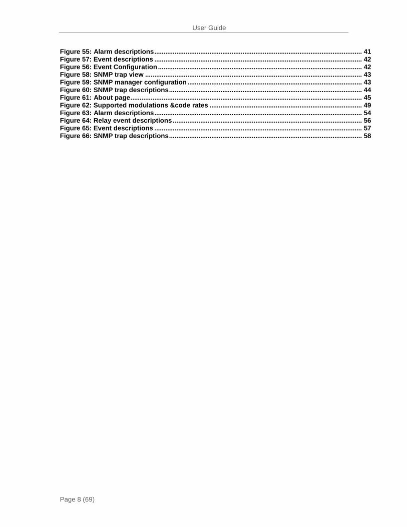
Figure 55: Alarm descriptions ................................................................................................................. 41 Figure 57: Event descriptions ................................................................................................................. 42 Figure 56: Event Configuration ............................................................................................................... 42 Figure 58: SNMP trap view ...................................................................................................................... 43 Figure 59: SNMP manager configuration ............................................................................................... 43 Figure 60: SNMP trap descriptions ......................................................................................................... 44 Figure 61: About page .............................................................................................................................. 45 Figure 62: Supported modulations &code rates ................................................................................... 49 Figure 63: Alarm descriptions ................................................................................................................. 54 Figure 64: Relay event descriptions ....................................................................................................... 56 Figure 65: Event descriptions ................................................................................................................. 57 Figure 66: SNMP trap descriptions ......................................................................................................... 58
User Guide
Page 9 (69)
Introduction
The SMD 9200 is a versatile DVB-S/S2 modulator platform capable of one or two channels of modulation per rack unit. The SMD 9200 comes standard with IP and ASI inputs to offer flexibility for future changes in network architecture or sourcing content from two different interfaces. The SMD also supports advanced DVB-S2 features such as 16APSK and 32APSK modulation as well as the carriage of multiple streams on a single RF carrier.
This manual describes how to install, configure, and operate the SMD 9200 DVB-S/S2 Modulator. It is written for professional operators of video distribution systems and assumes a prerequisite level of technical knowledge.
The SMD 9200is controllable through the front panel interface, a supported web browser and/or via SNMP which also provide alarms and traps that may be configured to alert users when errors occur through automation systems.
Through the SMD 9200 web interface, front panel, or SNMP the user can perform tasks such as configuration, monitoring, and troubleshooting.
Supported WEB interface browsers include:
-Internet Explorer 7 & above
- Mozilla Firefox 3.5& above
User Guide
Page 10 (69)
Abbreviations 16 APSK – 16 Amplitude and Phase Shift Keying 32 APSK – 32 Amplitude and Phase Shift Keying ASI – Asynchronous Serial Interface BISS – Basic Interoperable Scrambling System BNC – Bayonet Neill Concelman, Coax quick connect/disconnect BPS – Bits per second CAM – Conditional Access Module CAT – Conditional Access Table CI – Common Interface DHCP – Dynamic Host Configuration Protocol DVB – Digital Video Broadcasting FCC – Federal Communications Commission HD – High Definition IF – Intermediate Frequency I/O – Input/Output IP – Internet Protocol ISI – Intersymbol Interference LED – Light Emitting Diode MAC – Media Access Control Mbps – 1,000,000 bits per second MER – Modulation Error Ratio MPEG – Refers to standards developed by the ISO/IEC JTC1/SC29 WG11 MPEG-2 – Refers to ISO/IEC standards 13818-1 (Systems), 13818-2 (Video), 13818-3 (Audio), 13818-4 (Conformance) MPTS – Multiple Program Transport Stream NTP – Network Time Protocol PAT – Program Association Table PCR – Program Clock Reference PID – Packet Identifier PMT – Program Map Table QAM – Quadrature Amplitude Modulation QPSK – Quadrature Phase Shift Keying RF – Radio Frequency RU – Rack Unit RW – Read/Write SD – Standard Definition SI – Service Information SNMP – Simple Network Management Protocol SPTS – Single Program Transport Stream TS – Transport Stream
User Guide
Page 11 (69)
Hardware Overview
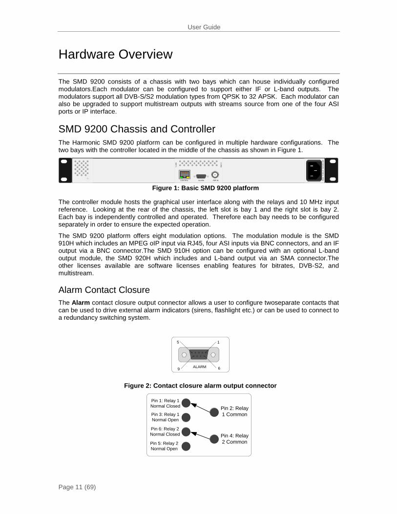
The SMD 9200 consists of a chassis with two bays which can house individually configured modulators.Each modulator can be configured to support either IF or L-band outputs. The modulators support all DVB-S/S2 modulation types from QPSK to 32 APSK. Each modulator can also be upgraded to support multistream outputs with streams source from one of the four ASI ports or IP interface.
SMD 9200 Chassis and Controller The Harmonic SMD 9200 platform can be configured in multiple hardware configurations. The two bays with the controller located in the middle of the chassis as shown in Figure 1.
CONTROL REF INALARM
BAY
2BAY 1
100-240VAC, 47-63H
z, 200W
The controller module hosts the graphical user interface along with the relays and 10 MHz input reference. Looking at the rear of the chassis, the left slot is bay 1 and the right slot is bay 2. Each bay is independently controlled and operated. Therefore each bay needs to be configured separately in order to ensure the expected operation.
The SMD 9200 platform offers eight modulation options. The modulation module is the SMD 910H which includes an MPEG oIP input via RJ45, four ASI inputs via BNC connectors, and an IF output via a BNC connector.The SMD 910H option can be configured with an optional L-band output module, the SMD 920H which includes and L-band output via an SMA connector.The other licenses available are software licenses enabling features for bitrates, DVB-S2, and multistream.
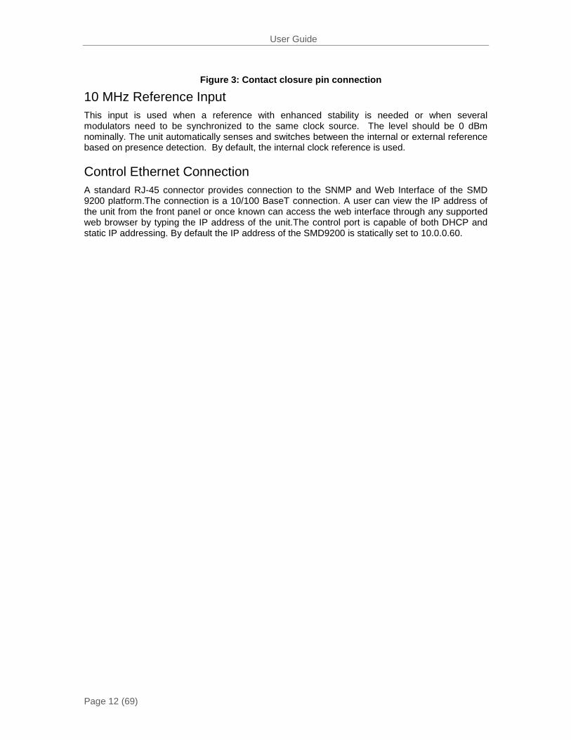
Alarm Contact Closure The Alarm contact closure output connector allows a user to configure twoseparate contacts that can be used to drive external alarm indicators (sirens, flashlight etc.) or can be used to connect to a redundancy switching system.
ALARM
1
6
5
9
Pin 2: Relay 1 Common
Pin 4: Relay 2 Common
Pin 1: Relay 1 Normal Closed
Pin 3: Relay 1 Normal Open
Pin 6: Relay 2 Normal Closed
Pin 5: Relay 2 Normal Open
Figure 1: Basic SMD 9200 platform
Figure 2: Contact closure alarm output connector
User Guide
Page 12 (69)
10 MHz Reference Input This input is used when a reference with enhanced stability is needed or when several modulators need to be synchronized to the same clock source. The level should be 0 dBm nominally. The unit automatically senses and switches between the internal or external reference based on presence detection. By default, the internal clock reference is used.
Control Ethernet Connection A standard RJ-45 connector provides connection to the SNMP and Web Interface of the SMD 9200 platform.The connection is a 10/100 BaseT connection. A user can view the IP address of the unit from the front panel or once known can access the web interface through any supported web browser by typing the IP address of the unit.The control port is capable of both DHCP and static IP addressing. By default the IP address of the SMD9200 is statically set to 10.0.0.60.
Figure 3: Contact closure pin connection

User Guide
Page 13 (69)
SMD 910H Option (Single Stream/IF Output) The SMD 910H Module option offers a single ASI and IP input. Both inputs are available by default and come standard on all option modules. The user is allowed to select the desired input in the front panel, web interface, and/or SNMP.The output is user selectable between 70 & 140 MHz.
The SMD 910H option has three different types of I/O as shown in Figure 4.
- Data input (RJ45 10/100/1000 auto detect speed &status) - ASI input (75 ohm BNC connector) - IF output (75 ohm BNC connector)
SMD 920H Option (L-Band Output) The SMD 920H module in combination with the SMD 910H offers a single or multiple ASI and IP input(s).Both ASI and IP inputs are available by default and come standard on all option modules. The user is allowed to select the desired input in the front panel, web interface, and/or SNMP. The output is looped out from the IF output into the L-Band upconverter.The L-band frequency is user settable for 950 to 2150 MHz.
IF OUT
IF IN
1 2 3 4DATA IN
L-BAND OUTMON PRI
ASI IN
The SMD 920H option has six different types of I/O as shown in Figure 5.
Data input (RJ45 10/100/1000 auto detect speed & status)
ASI input (75 ohm BNC connector)
IF output (75 ohm BNC connector)
Upconverter IF input (75 ohm BNC Connector)
L-band primary output (50 ohm SMA connector)
L-band monitor output (50 ohm SMA connector -20 dBc from primary)
Figure 4: SMD 910H single TS input with IF output
Figure 5: SMD 920H L-Band output
User Guide
Page 14 (69)
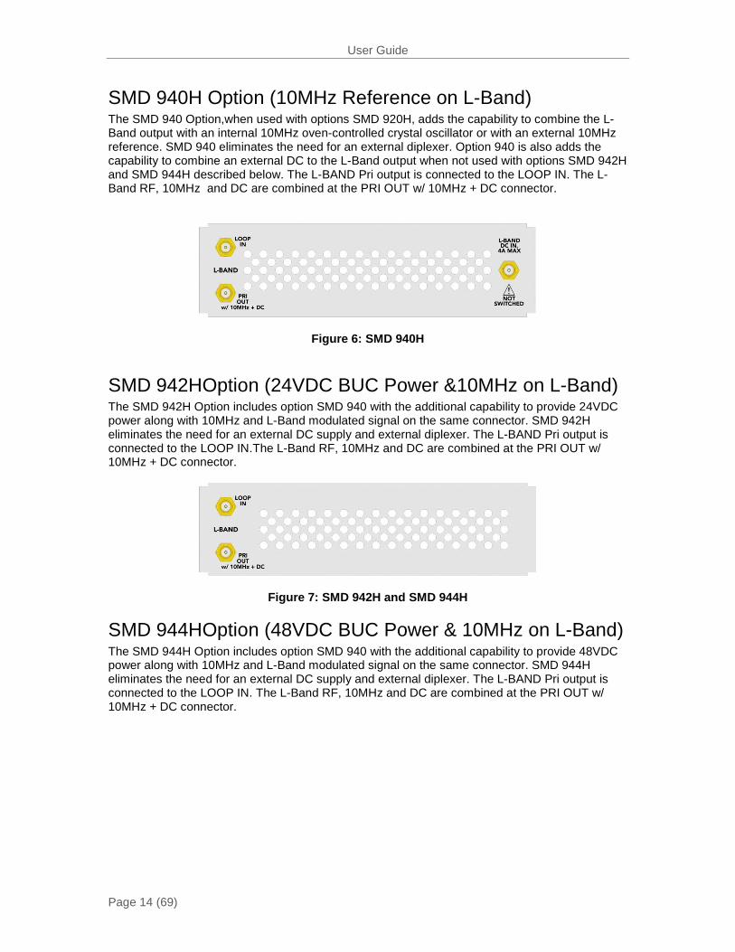
SMD 940H Option (10MHz Reference on L-Band) The SMD 940 Option,when used with options SMD 920H, adds the capability to combine the L-Band output with an internal 10MHz oven-controlled crystal oscillator or with an external 10MHz reference. SMD 940 eliminates the need for an external diplexer. Option 940 is also adds the capability to combine an external DC to the L-Band output when not used with options SMD 942H and SMD 944H described below. The L-BAND Pri output is connected to the LOOP IN. The L-Band RF, 10MHz and DC are combined at the PRI OUT w/ 10MHz + DC connector.
Figure 6: SMD 940H
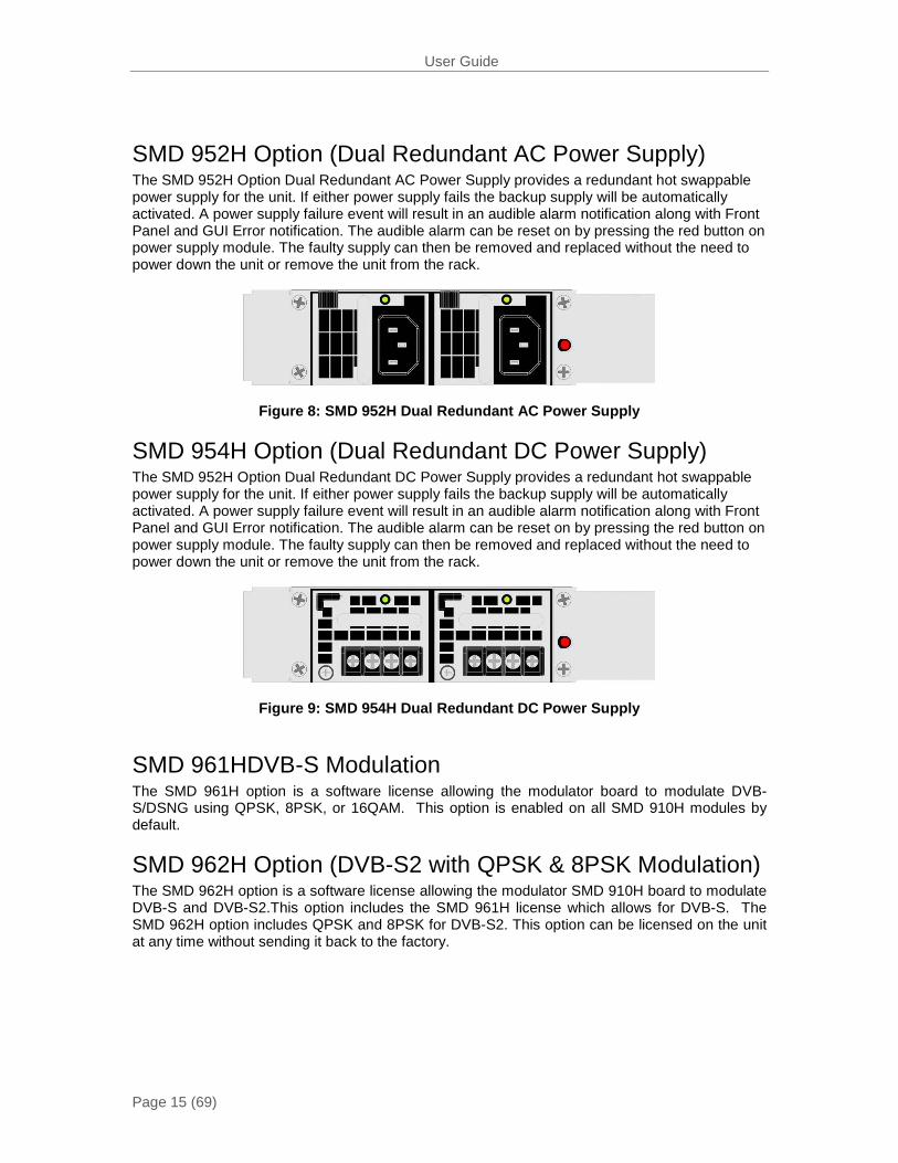
SMD 942HOption (24VDC BUC Power &10MHz on L-Band) The SMD 942H Option includes option SMD 940 with the additional capability to provide 24VDC power along with 10MHz and L-Band modulated signal on the same connector. SMD 942H eliminates the need for an external DC supply and external diplexer. The L-BAND Pri output is connected to the LOOP IN.The L-Band RF, 10MHz and DC are combined at the PRI OUT w/ 10MHz + DC connector.
Figure 7: SMD 942H and SMD 944H
SMD 944HOption (48VDC BUC Power & 10MHz on L-Band) The SMD 944H Option includes option SMD 940 with the additional capability to provide 48VDC power along with 10MHz and L-Band modulated signal on the same connector. SMD 944H eliminates the need for an external DC supply and external diplexer. The L-BAND Pri output is connected to the LOOP IN. The L-Band RF, 10MHz and DC are combined at the PRI OUT w/ 10MHz + DC connector.
User Guide
Page 15 (69)
SMD 952H Option (Dual Redundant AC Power Supply) The SMD 952H Option Dual Redundant AC Power Supply provides a redundant hot swappable power supply for the unit. If either power supply fails the backup supply will be automatically activated. A power supply failure event will result in an audible alarm notification along with Front Panel and GUI Error notification. The audible alarm can be reset on by pressing the red button on power supply module. The faulty supply can then be removed and replaced without the need to power down the unit or remove the unit from the rack.
Figure 8: SMD 952H Dual Redundant AC Power Supply
SMD 954H Option (Dual Redundant DC Power Supply) The SMD 952H Option Dual Redundant DC Power Supply provides a redundant hot swappable power supply for the unit. If either power supply fails the backup supply will be automatically activated. A power supply failure event will result in an audible alarm notification along with Front Panel and GUI Error notification. The audible alarm can be reset on by pressing the red button on power supply module. The faulty supply can then be removed and replaced without the need to power down the unit or remove the unit from the rack.
Figure 9: SMD 954H Dual Redundant DC Power Supply
SMD 961HDVB-S Modulation The SMD 961H option is a software license allowing the modulator board to modulate DVB-S/DSNG using QPSK, 8PSK, or 16QAM. This option is enabled on all SMD 910H modules by default.
SMD 962H Option (DVB-S2 with QPSK & 8PSK Modulation) The SMD 962H option is a software license allowing the modulator SMD 910H board to modulate DVB-S and DVB-S2.This option includes the SMD 961H license which allows for DVB-S. The SMD 962H option includes QPSK and 8PSK for DVB-S2. This option can be licensed on the unit at any time without sending it back to the factory.
User Guide
Page 16 (69)
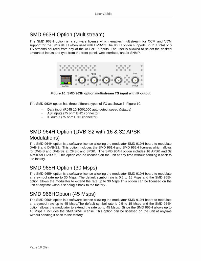
SMD 963H Option (Multistream) The SMD 963H option is a software license which enables multistream for CCM and VCM support for the SMD 910H when used with DVB-S2.The 963H option supports up to a total of 6 TS streams sourced from any of the ASI or IP inputs. The user is allowed to select the desired amount of inputs and type from the front panel, web interface, and/or SNMP.
IF OUT
IF IN
1 2 3 4DATA IN
ASI IN
The SMD 963H option has three different types of I/O as shown in Figure 10.
- Data input (RJ45 10/100/1000 auto detect speed &status) - ASI inputs (75 ohm BNC connector) - IF output (75 ohm BNC connector)
SMD 964H Option (DVB-S2 with 16 & 32 APSK Modulations) The SMD 964H option is a software license allowing the modulator SMD 910H board to modulate DVB-S and DVB-S2. This option includes the SMD 961H and SMD 962H licenses which allows for DVB-S and DVB-S2 at QPSK and 8PSK. The SMD 964H option includes 16 APSK and 32 APSK for DVB-S2. This option can be licensed on the unit at any time without sending it back to the factory.
SMD 965H Option (30 Msps) The SMD 965H option is a software license allowing the modulator SMD 910H board to modulate at a symbol rate up to 30 Msps. The default symbol rate is 0.5 to 15 Msps and the SMD 965H option allows the modulator to extend the rate up to 30 Msps.This option can be licensed on the unit at anytime without sending it back to the factory.
SMD 966HOption (45 Msps) The SMD 966H option is a software license allowing the modulator SMD 910H board to modulate at a symbol rate up to 45 Msps.The default symbol rate is 0.5 to 15 Msps and the SMD 966H option allows the modulator to extend the rate up to 45 Msps. Since the SMD 966H allows up to 45 Msps it includes the SMD 965H license. This option can be licensed on the unit at anytime without sending it back to the factory.
Figure 10: SMD 963H option multistream TS input with IF output
User Guide
Page 17 (69)
Installation
General Considerations This section describes the installation procedure for the SMD 9200.
Rack size The chassis is designed to be installed in a standard 19-inch rack. The SMD 9200 occupies 1RU of rack space. All of the cable connections are located on the rear of the unit.
Ventilation The SMD 9200 is cooled via forced induction through the front of the unit and exhausted through the vents in the rear.The SMD 9200 is equipped with a temperature monitors to ensure operating temperature is maintained.
Power Connection Using the proper power connections is vital to the safe operation of the SMD9200.Only use the supplied 3-prong power connector or one with equal specifications.
AC Power Connection The SMD 9200 is capable of either operating on 120V or 240V systems.The power supply will automatically detect the system it is connected to. To hook up the power use the following steps:
1. Locate the AC power cord included with the SMD 9200.
2. Plug the female end of the power cord (end with no prongs) into the back of the unit.
3. Locate a protected outlet (usually inside of the rack) to plug the male end of the power cable into.
AC Dual Redundant Power Connection(optional) The Dual Redundant option allows theSMD9200to be powered by two separate AC supplies either operating on 120V or 240V systems. The power supply will automatically detect the system it is connected to. To hook up the power use the following steps:
1. Locate the AC power cords included with the SMD 9200.
2. Plug the female end of the power cords (end with no prongs) into the back of the unit.
3. Locate a protected outlet (usually inside of the rack) to plug the male end of the power cord into.
DC Dual Redundant Power Connection (optional) The Dual Redundant option allows the SMD 9200 to be powered by two separate DC supplies operating on a -48VDC system. To hook up the power use the following steps:
1. Connect the negative 48VDC to the terminal labeled -48V.
2. Connect ground to the terminal labeled 0V
User Guide
Page 18 (69)
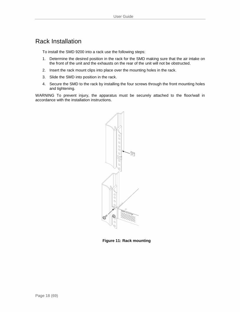
Rack Installation To install the SMD 9200 into a rack use the following steps:
1. Determine the desired position in the rack for the SMD making sure that the air intake on the front of the unit and the exhausts on the rear of the unit will not be obstructed.
2. Insert the rack mount clips into place over the mounting holes in the rack.
3. Slide the SMD into position in the rack.
4. Secure the SMD to the rack by installing the four screws through the front mounting holes and tightening.
WARNING To prevent injury, the apparatus must be securely attached to the floor/wall in accordance with the installation instructions.
Figure 11: Rack mounting
User Guide
Page 19 (69)
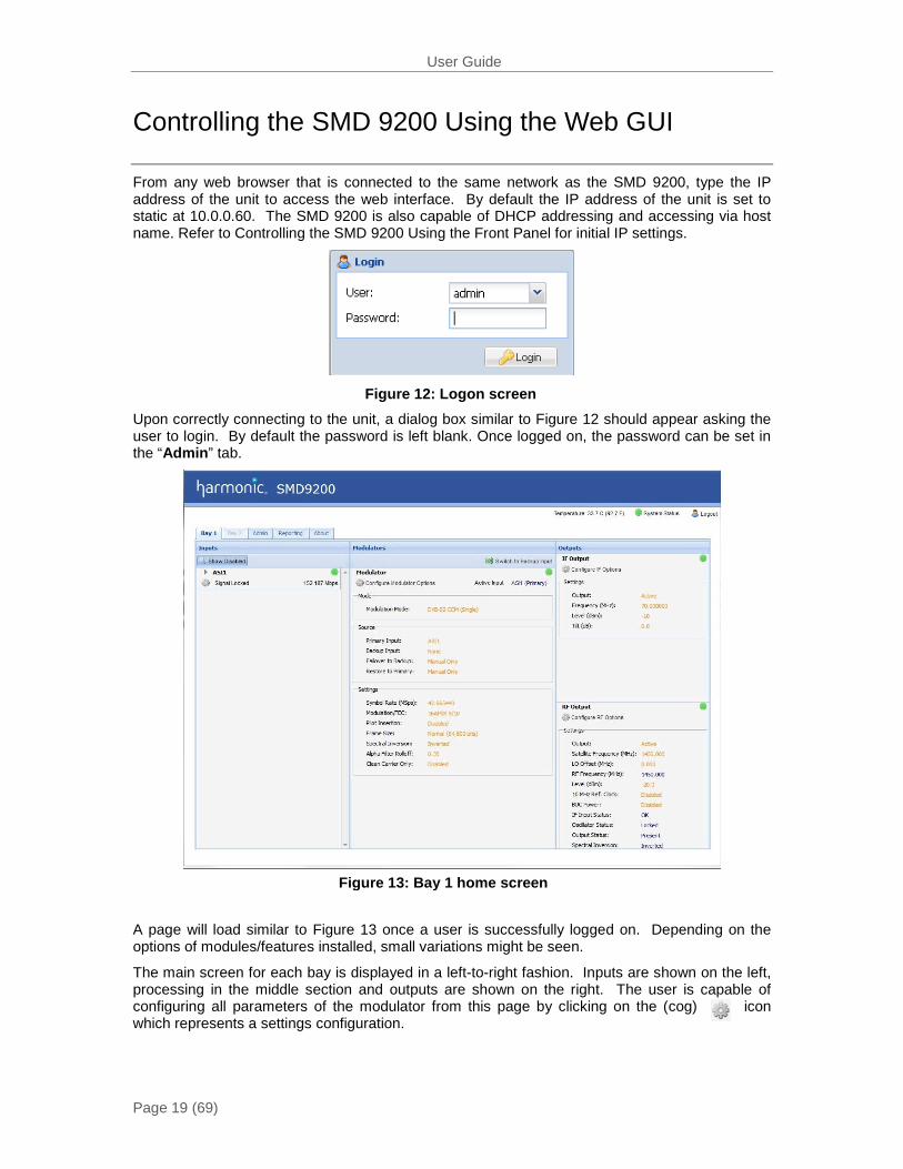
Figure 13: Bay 1 home screen
Figure 12: Logon screen
Controlling the SMD 9200 Using the Web GUI
From any web browser that is connected to the same network as the SMD 9200, type the IP address of the unit to access the web interface. By default the IP address of the unit is set to static at 10.0.0.60. The SMD 9200 is also capable of DHCP addressing and accessing via host name. Refer to Controlling the SMD 9200 Using the Front Panel for initial IP settings.
Upon correctly connecting to the unit, a dialog box similar to Figure 12 should appear asking the user to login. By default the password is left blank. Once logged on, the password can be set in the “Admin” tab.
A page will load similar to Figure 13 once a user is successfully logged on. Depending on the options of modules/features installed, small variations might be seen.
The main screen for each bay is displayed in a left-to-right fashion. Inputs are shown on the left, processing in the middle section and outputs are shown on the right. The user is capable of configuring all parameters of the modulator from this page by clicking on the (cog) icon which represents a settings configuration.

User Guide
Page 20 (69)
ASI Inputs All the inputs are shown on the left column of the home screen for each bay. If the unit is only configured for single stream, only one ASI will be shown under inputs along with a single IP input. If multistream Option is licensed, (4) ASI inputs and (6) IP inputs will be shown in the inputs section.
Clicking on the “►” sign by each ASI port allows the advanced details to be shown for the port. ASI only has a few advanced details so little will be shown. The calculated input bitrate is shown in Mbps.
If the port is enabled and no sync is detected, an error will be indicated by a red light. Errors can be user enabled/disabled if desired. Please see Reporting Section for details.
Figure 16 presents the ASI settings, by default all input ports are enabled, but by clicking on the settings tab for each ASI input and disabling the port, moves the port into the Disabled list allowing for customizing the view for quick reference. The input can be returned to the enabled section by enabling the port in the settings tab.
Each input port allows the user to set a local Alias for each port. This is a friendly name that can be used to name the input for easy reference in the future.
Figure 14: Single ASI input
Figure 15: Multistream ASI input
Figure 16: ASI configuration

User Guide
Page 21 (69)
IP Inputs All the inputs are shown on the left column of the home screen for each bay. If the unit is only configured for single stream, only one IP will be shown under inputs along with a single ASI Input. If multistream is enabled, (6) IP inputs and (4) ASI inputs will be shown in the inputs section.
Clicking on the triangle by each IP port allows the advanced details to be shown for the port as shown in Figure 17. IP advanced details such as IGMP data and input buffers will be shown.
The calculated input bitrate is shown in Mbps.
If the port is enabled and no sync is detected, an error will be indicated by a red light. Errors can be user enabled/disabled if desired. Please see Reporting Section for details.
Figure 18 represents the IP settings for an individual IP source, by default all input ports are enabled, but by clicking on the settings tab for each IP input and disabling the port, moves the port into the Disabled list, allowing for customizing the view for quick reference. The input can be returned to the enabled section by enabling the port in the settings tab.
Figure 17: Expanded IP status
User Guide
Page 22 (69)
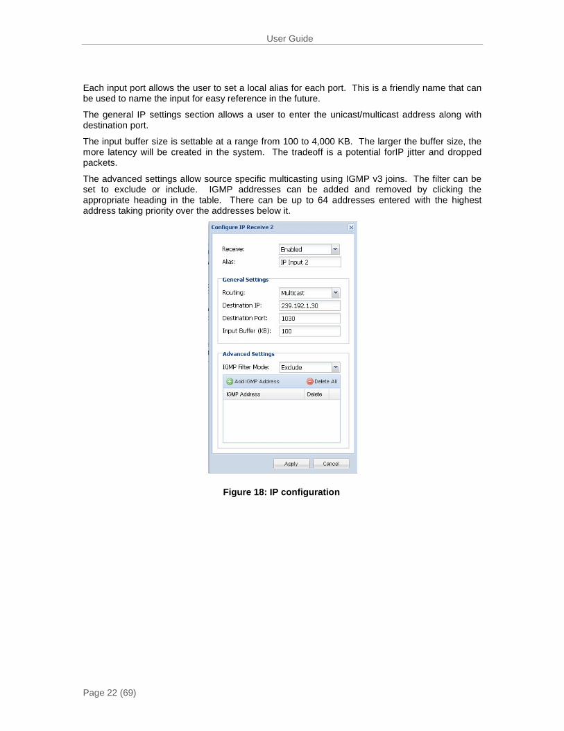
Each input port allows the user to set a local alias for each port. This is a friendly name that can be used to name the input for easy reference in the future.
The general IP settings section allows a user to enter the unicast/multicast address along with destination port.
The input buffer size is settable at a range from 100 to 4,000 KB. The larger the buffer size, the more latency will be created in the system. The tradeoff is a potential forIP jitter and dropped packets.
The advanced settings allow source specific multicasting using IGMP v3 joins. The filter can be set to exclude or include. IGMP addresses can be added and removed by clicking the appropriate heading in the table. There can be up to 64 addresses entered with the highest address taking priority over the addresses below it.
Figure 18: IP configuration
User Guide
Page 23 (69)
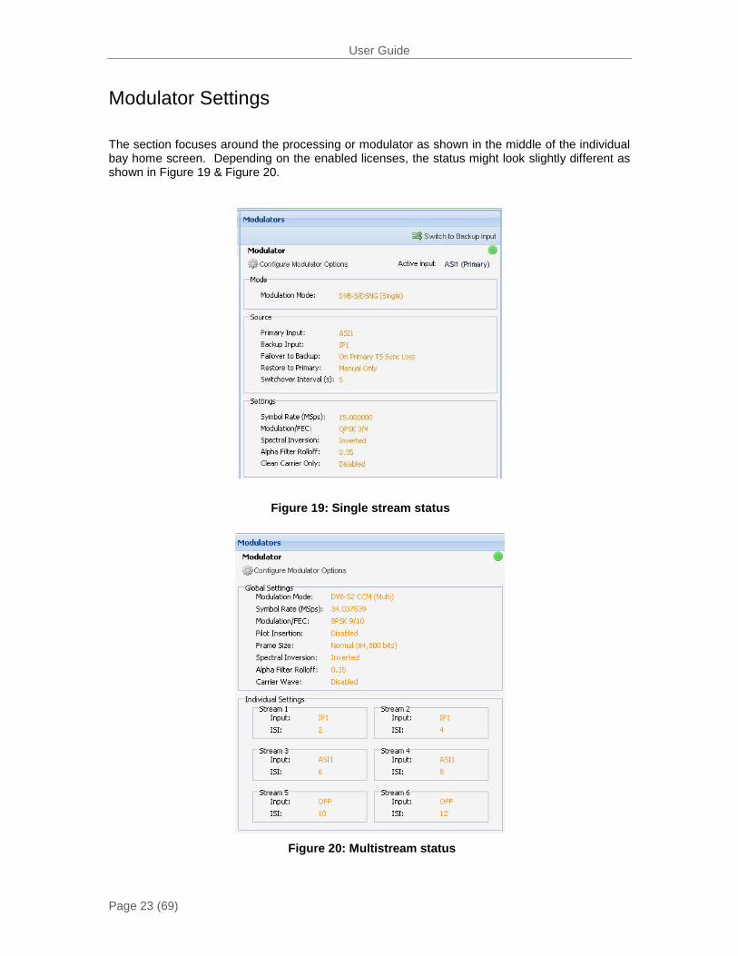
Modulator Settings
The section focuses around the processing or modulator as shown in the middle of the individual bay home screen. Depending on the enabled licenses, the status might look slightly different as shown in Figure 19 & Figure 20.
Figure 19: Single stream status
Figure 20: Multistream status
User Guide
Page 24 (69)
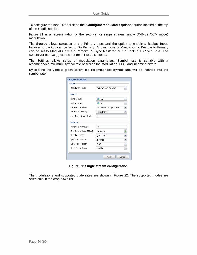
To configure the modulator click on the “Configure Modulator Options” button located at the top of the middle section.
Figure 21 is a representation of the settings for single stream (single DVB-S2 CCM mode) modulation.
The Source allows selection of the Primary Input and the option to enable a Backup Input. Failover to Backup can be set to On Primary TS Sync Loss or Manual Only. Restore to Primary can be set to Manual Only, On Primary TS Sync Restored or On Backup TS Sync Loss. The switchover Interval(s) can be set from 1 to 20 seconds.
The Settings allows setup of modulation parameters. Symbol rate is settable with a recommended minimum symbol rate based on the modulation, FEC, and incoming bitrate.
By clicking the vertical green arrow, the recommended symbol rate will be inserted into the symbol rate.
The modulations and supported code rates are shown in Figure 22. The supported modes are selectable in the drop down list.
Figure 21: Single stream configuration

User Guide
Page 25 (69)
DVB-S/DSNG DVB-S2
Code Rate
QPSK 8PSK 16QAM QPSK 8PSK 16APSK 32APSK
1/4 √
1/3 √
2/5 √
1/2 √ √
3/5 √ √
2/3 √ √ √ √ √
3/4 √ √ √ √ √ √
4/5 √ √ √
5/6 √ √ √ √ √ √
7/8 √ √
8/9 √ √ √ √ √
9/10 √ √ √ √
The remaining settings include (Bold indicates default):
Pilot Insertion (Only available in DVB-S2 Modes)
- Enable
- Disable
Description: When enabled, every 16 slots of 90 symbols the modulator will insert 36 non-modulated symbols to aid in receiver synchronization. The use of pilots will allow the receiver to maintain carrier recovery, even when the user data payload cannot be decoded.
Frame Size (Only available in DVB-S2 Modes)
- Normal (64,800 bits)
- Short (16,200 bits)
Description: Short frames introduce more overhead but give a shorter encapsulation delay. Short frames are 4 time shorter than normal frames.
Spectral Inversion
- Normal (When SMD 920H is not present)
- Inverted
Description: Determines whether the spectrum is inverted or normal. Note: When the SMD 920H L-Band option is installed, the default spectral inversion is inverted as the upconverter is set to invert. Setting the output to Inverted will give a normal output from the upconverter.
Figure 22: Supported modulations &code rates
User Guide
Page 26 (69)
Alpha Filter Rolloff
- 0.35
- 0.25
- 0.20
Description: The filter rolloff is known as the Alpha coefficient (α). The smaller the α, the less bandwidth will be required on the satellite.
Carrier Wave - Disabled
- Enabled
Description:This is used for calibration and verification of spectrum polarity.
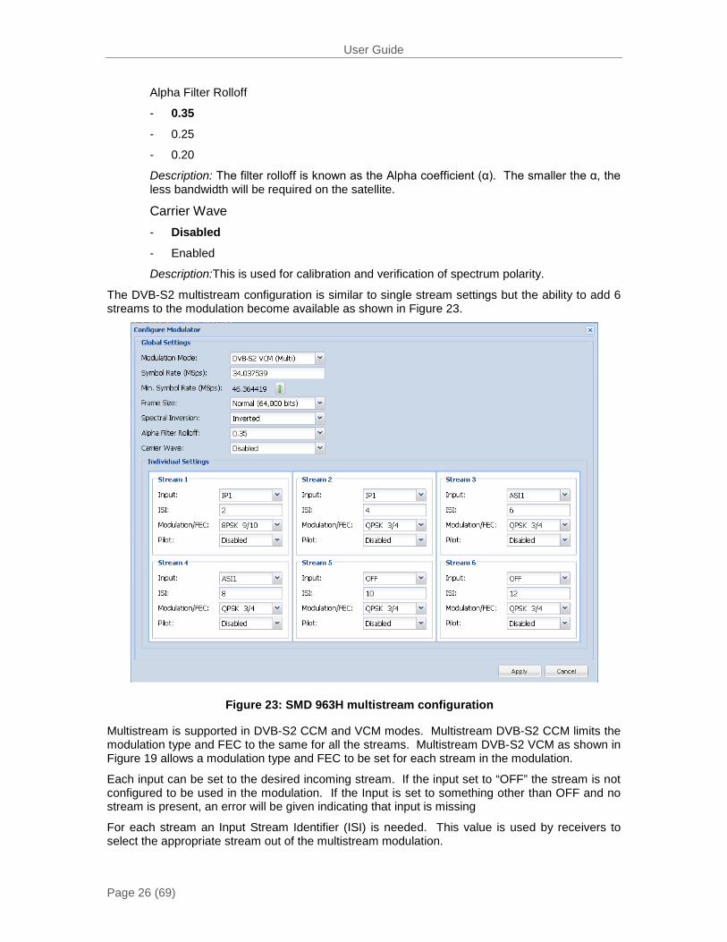
The DVB-S2 multistream configuration is similar to single stream settings but the ability to add 6 streams to the modulation become available as shown in Figure 23.
Multistream is supported in DVB-S2 CCM and VCM modes. Multistream DVB-S2 CCM limits the modulation type and FEC to the same for all the streams. Multistream DVB-S2 VCM as shown in Figure 19 allows a modulation type and FEC to be set for each stream in the modulation.
Each input can be set to the desired incoming stream. If the input set to “OFF” the stream is not configured to be used in the modulation. If the Input is set to something other than OFF and no stream is present, an error will be given indicating that input is missing
For each stream an Input Stream Identifier (ISI) is needed. This value is used by receivers to select the appropriate stream out of the multistream modulation.
Figure 23: SMD 963H multistream configuration
User Guide
Page 27 (69)
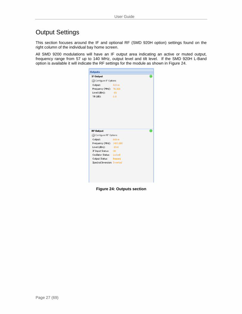
Output Settings This section focuses around the IF and optional RF (SMD 920H option) settings found on the right column of the individual bay home screen.
All SMD 9200 modulations will have an IF output area indicating an active or muted output, frequency range from 57 up to 140 MHz, output level and tilt level. If the SMD 920H L-Band option is available it will indicate the RF settings for the module as shown in Figure 24.
Figure 24: Outputs section

User Guide
Page 28 (69)
IF Output Clicking on “Configure IF Options” will produce a dialog box as shown in Figure 25.
The output can be set as active or mute
The IF output frequency is selectable between 57& 140 MHz in 1 Hz increments
The level for the IF output is adjustable between -30 to -5 dBm
The tilt adjustment allows a user to adjust the overall slope of the output spectrum. The range is selectable from -3 to +3 dB.
RF Ouput
If the RF L-Band SMD 920H option is installed in the SMD 9200 bay, the ability to configure the RF output is also shown. By clicking on the “Configure RF Options,” a dialog box will appear as shown in Figure 26.
The output can be set as active or mute
The output frequency is settable at a range of 950 to 2150 MHz, When LO Offset is 0MHz.
The LO Offset (MHz) can be entered to allow the desired Satellite Frequency (MHz) to be entered. The SMD9200 will output the proper frequency to achieve the correct satellite frequency when combined with the external UpconverterLO (Local Oscillator). This eliminates the need to determine what the output frequency of the SMD9200 should be to achieve the desired satellite frequency. In the example settings below the output of the SMD9200 will be the same.
The output level is settable at a range of -30 to 5 dBm.
Figure 25: IF settings
Figure 26: RF settings
User Guide
Page 29 (69)
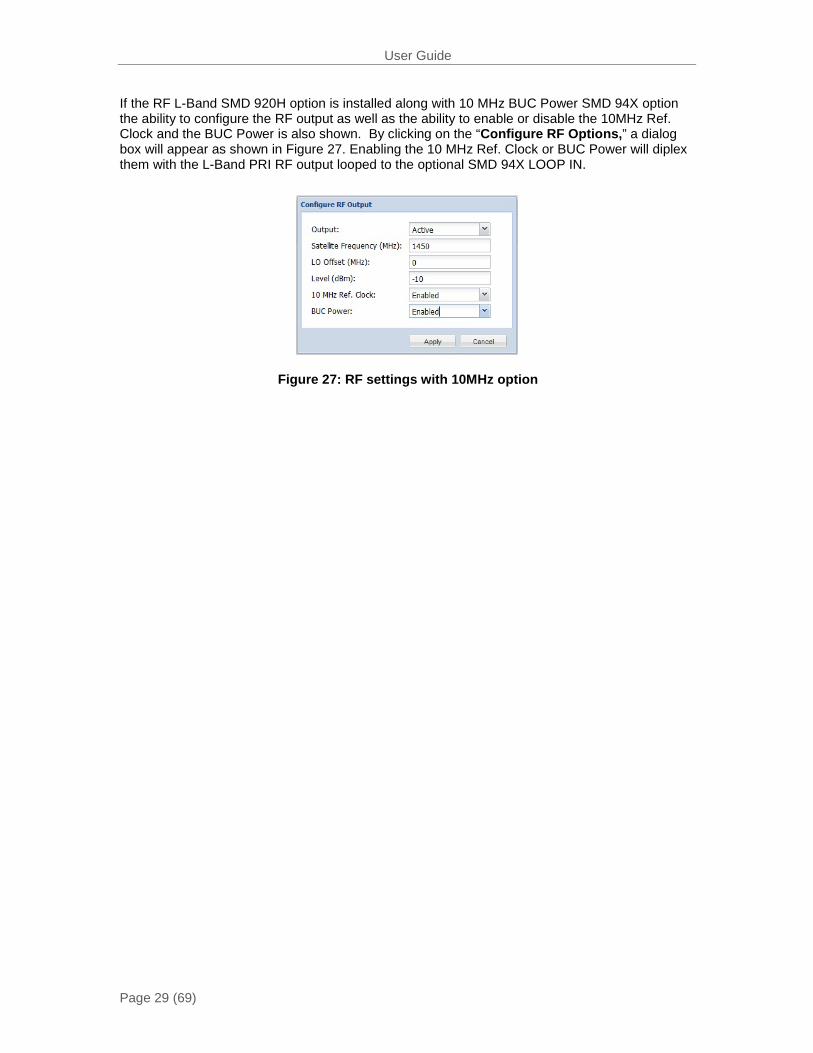
If the RF L-Band SMD 920H option is installed along with 10 MHz BUC Power SMD 94X option the ability to configure the RF output as well as the ability to enable or disable the 10MHz Ref. Clock and the BUC Power is also shown. By clicking on the “Configure RF Options,” a dialog box will appear as shown in Figure 27. Enabling the 10 MHz Ref. Clock or BUC Power will diplex them with the L-Band PRI RF output looped to the optional SMD 94X LOOP IN.
Figure 27: RF settings with 10MHz option
User Guide
Page 30 (69)
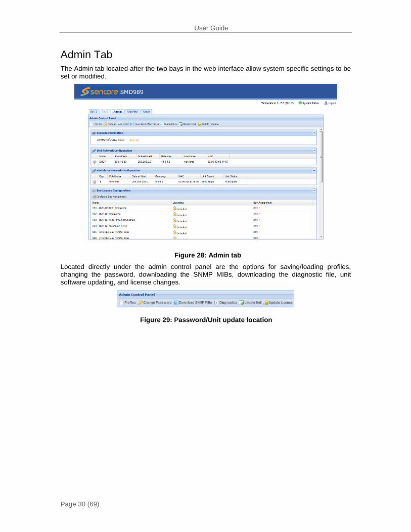
Admin Tab The Admin tab located after the two bays in the web interface allow system specific settings to be set or modified.
Located directly under the admin control panel are the options for saving/loading profiles, changing the password, downloading the SNMP MIBs, downloading the diagnostic file, unit software updating, and license changes.
Figure 28: Admin tab
Figure 29: Password/Unit update location
User Guide
Page 31 (69)
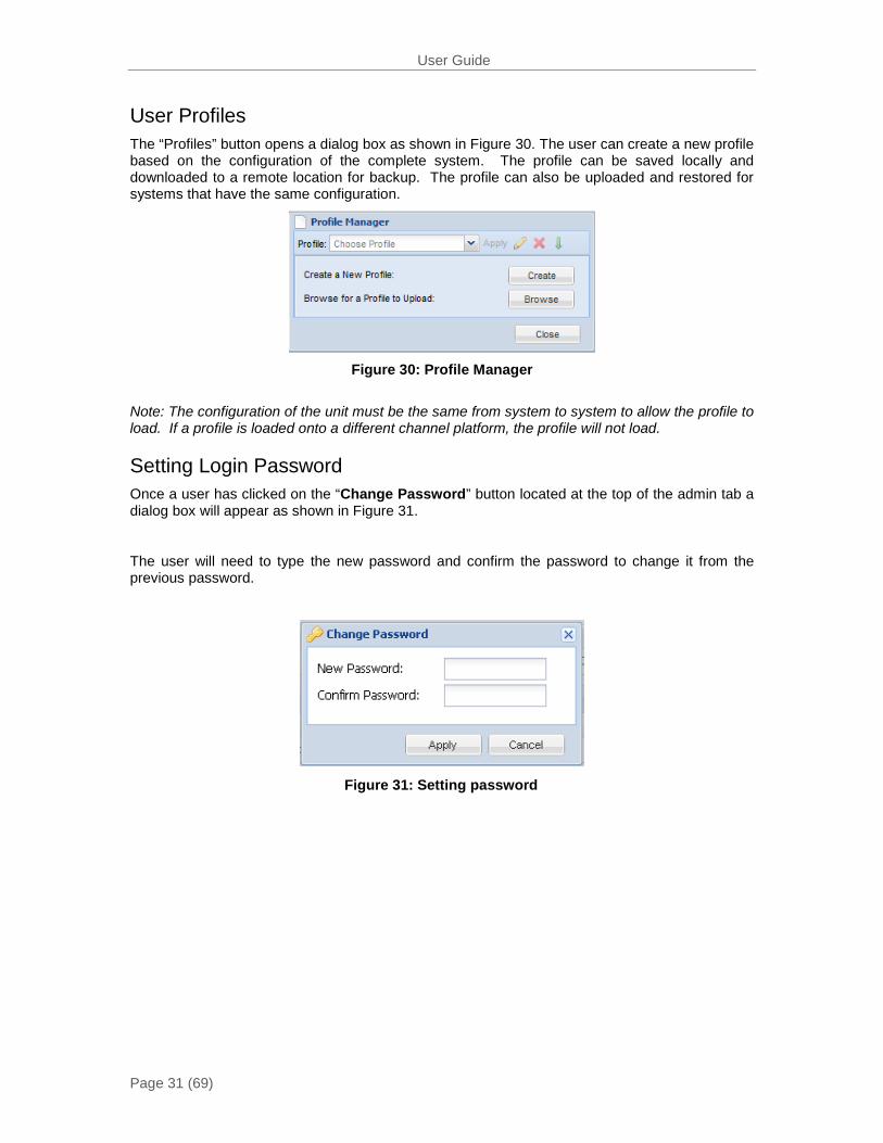
User Profiles The “Profiles” button opens a dialog box as shown in Figure 30. The user can create a new profile based on the configuration of the complete system. The profile can be saved locally and downloaded to a remote location for backup. The profile can also be uploaded and restored for systems that have the same configuration.
Figure 30: Profile Manager
Note: The configuration of the unit must be the same from system to system to allow the profile to load. If a profile is loaded onto a different channel platform, the profile will not load.
Setting Login Password Once a user has clicked on the “Change Password” button located at the top of the admin tab a dialog box will appear as shown in Figure 31.
The user will need to type the new password and confirm the password to change it from the previous password.
Figure 31: Setting password
User Guide
Page 32 (69)
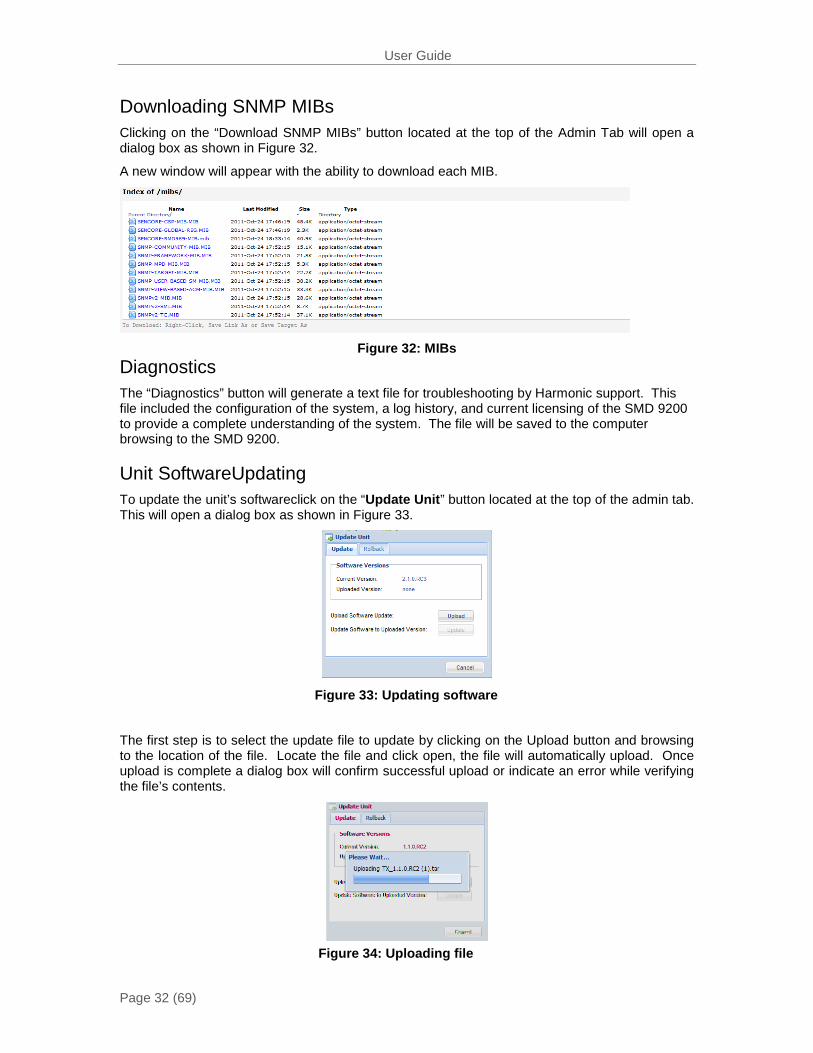
Downloading SNMP MIBs Clicking on the “Download SNMP MIBs” button located at the top of the Admin Tab will open a dialog box as shown in Figure 32.
A new window will appear with the ability to download each MIB.
Figure 32: MIBs
Diagnostics The “Diagnostics” button will generate a text file for troubleshooting by Harmonic support. This file included the configuration of the system, a log history, and current licensing of the SMD 9200 to provide a complete understanding of the system. The file will be saved to the computer browsing to the SMD 9200.
Unit SoftwareUpdating To update the unit’s softwareclick on the “Update Unit” button located at the top of the admin tab. This will open a dialog box as shown in Figure 33.
The first step is to select the update file to update by clicking on the Upload button and browsing to the location of the file. Locate the file and click open, the file will automatically upload. Once upload is complete a dialog box will confirm successful upload or indicate an error while verifying the file’s contents.
Figure 33: Updating software
Figure 34: Uploading file

User Guide
Page 33 (69)
Once uploaded successfully, the uploaded version will appear on the Update Unit dialog screen.
Figure 35: Upload successful
To complete update click on the update button and the unit will commence with the update process indicating when update is complete.
Figure 36: Update confirmation
Figure 37: Updating unit
Once update is complete the system will be restarted. The user will be prompted to log back into the web interface once the unit is updated and operational.
Figure 38: Unit restarting
User Guide
Page 34 (69)
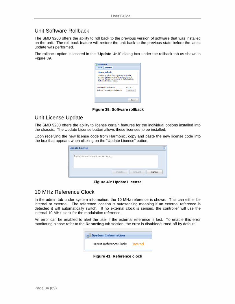
Unit Software Rollback The SMD 9200 offers the ability to roll back to the previous version of software that was installed on the unit. The roll back feature will restore the unit back to the previous state before the latest update was performed.
The rollback option is located in the “Update Unit” dialog box under the rollback tab as shown in Figure 39.
Unit License Update The SMD 9200 offers the ability to license certain features for the individual options installed into the chassis. The Update License button allows these licenses to be installed.
Upon receiving the new license code from Harmonic, copy and paste the new license code into the box that appears when clicking on the “Update License” button.
Figure 40: Update License
10 MHz Reference Clock In the admin tab under system information, the 10 MHz reference is shown. This can either be internal or external. The reference location is autosensing meaning if an external reference is detected it will automatically switch. If no external clock is sensed, the controller will use the internal 10 MHz clock for the modulation reference.
An error can be enabled to alert the user if the external reference is lost. To enable this error monitoring please refer to the Reporting tab section, the error is disabled/turned-off by default.
Figure 39: Software rollback
Figure 41: Reference clock
User Guide
Page 35 (69)
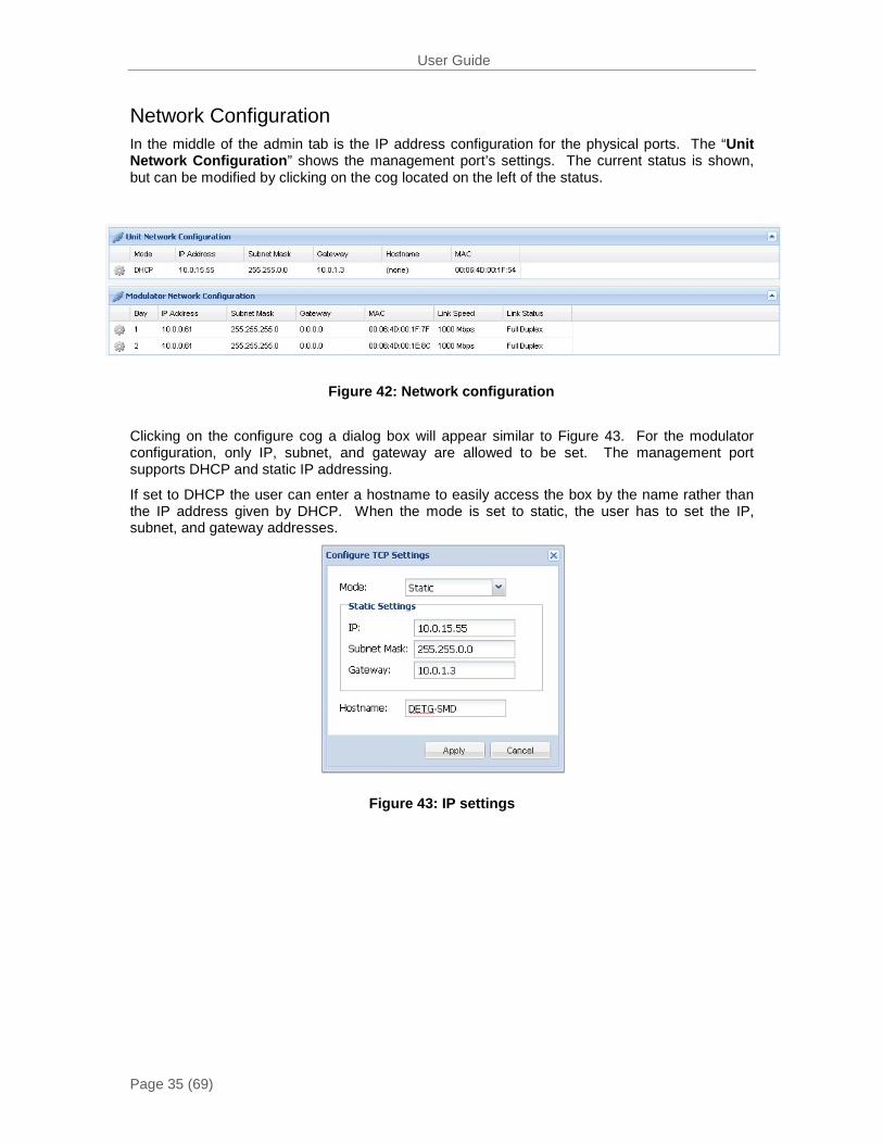
Network Configuration
In the middle of the admin tab is the IP address configuration for the physical ports. The “Unit Network Configuration” shows the management port’s settings. The current status is shown, but can be modified by clicking on the cog located on the left of the status.
Clicking on the configure cog a dialog box will appear similar to Figure 43. For the modulator configuration, only IP, subnet, and gateway are allowed to be set. The management port supports DHCP and static IP addressing.
If set to DHCP the user can enter a hostname to easily access the box by the name rather than the IP address given by DHCP. When the mode is set to static, the user has to set the IP, subnet, and gateway addresses.
Figure 42: Network configuration
Figure 43: IP settings
User Guide
Page 36 (69)
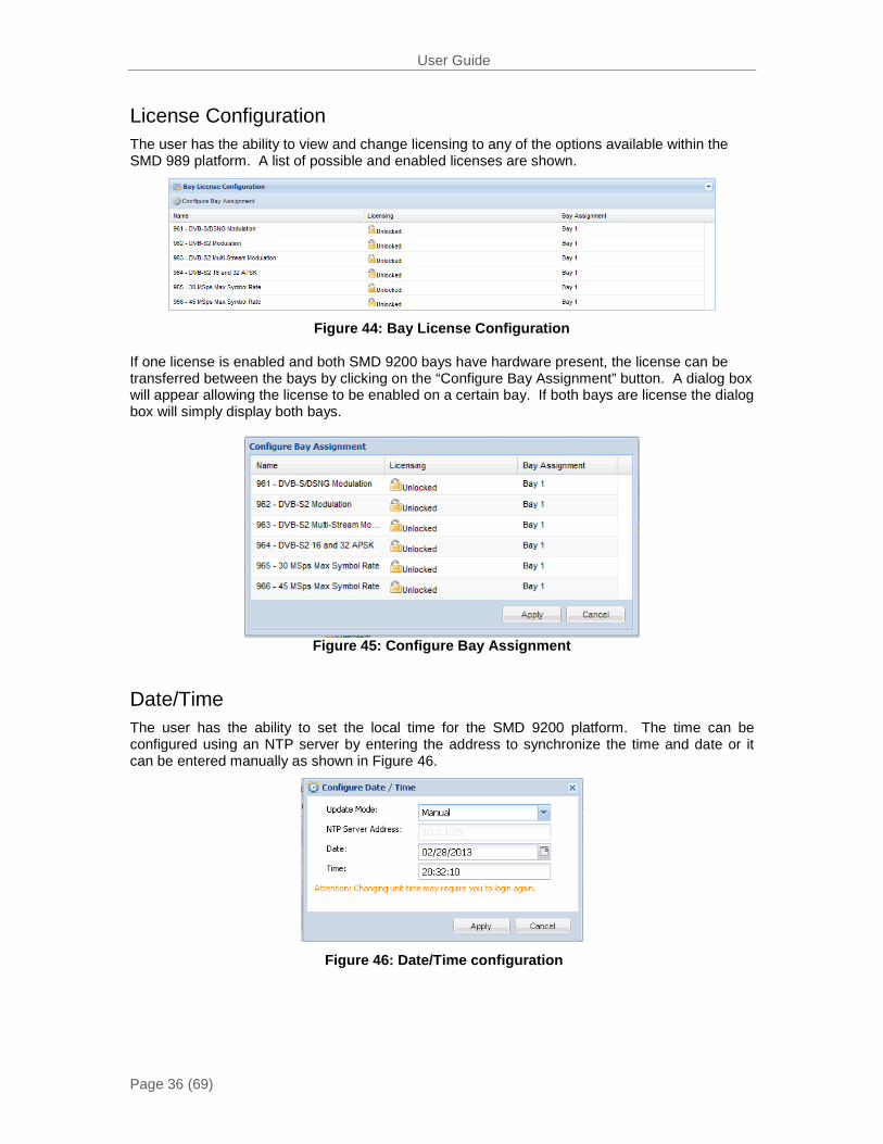
License Configuration The user has the ability to view and change licensing to any of the options available within the SMD 989 platform. A list of possible and enabled licenses are shown.
Figure 44: Bay License Configuration
If one license is enabled and both SMD 9200 bays have hardware present, the license can be transferred between the bays by clicking on the “Configure Bay Assignment” button. A dialog box will appear allowing the license to be enabled on a certain bay. If both bays are license the dialog box will simply display both bays.
Figure 45: Configure Bay Assignment
Date/Time The user has the ability to set the local time for the SMD 9200 platform. The time can be configured using an NTP server by entering the address to synchronize the time and date or it can be entered manually as shown in Figure 46.
Figure 46: Date/Time configuration
User Guide
Page 37 (69)
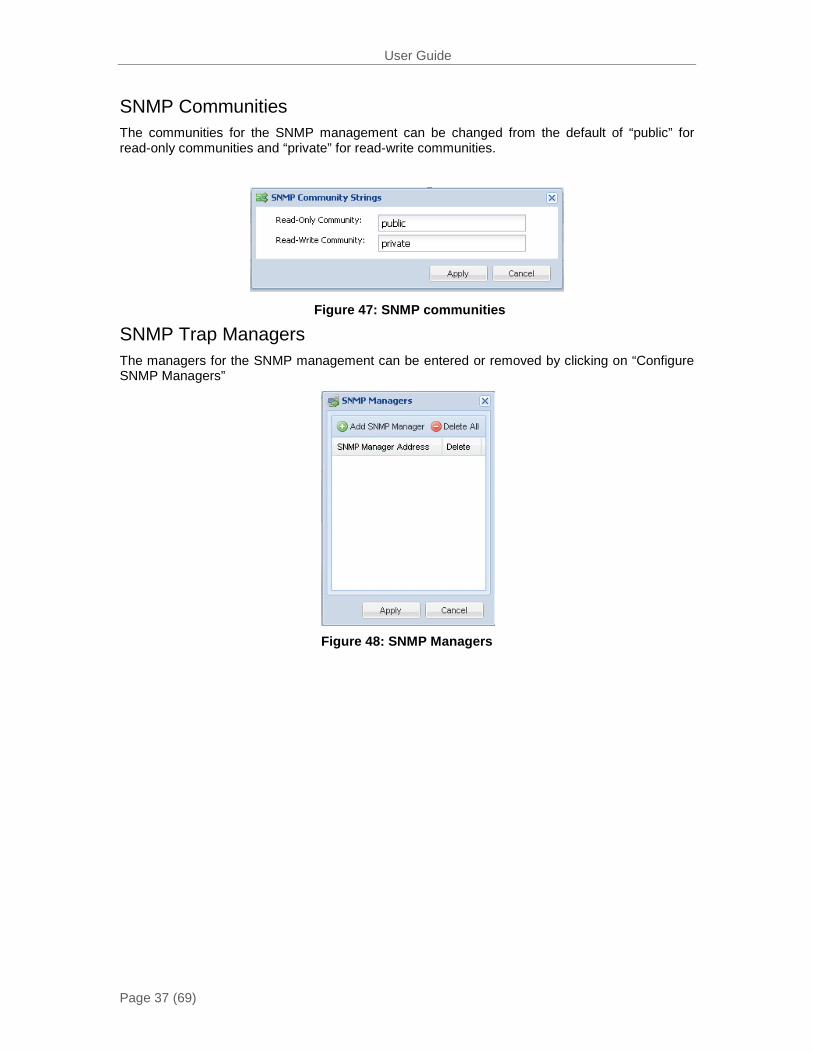
SNMP Communities The communities for the SNMP management can be changed from the default of “public” for read-only communities and “private” for read-write communities.
SNMP Trap Managers The managers for the SNMP management can be entered or removed by clicking on “Configure SNMP Managers”
Figure 48: SNMP Managers
Figure 47: SNMP communities
User Guide
Page 38 (69)
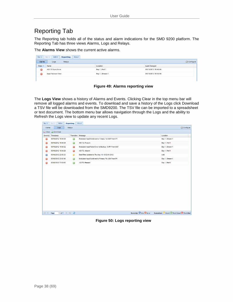
Reporting Tab The Reporting tab holds all of the status and alarm indications for the SMD 9200 platform. The Reporting Tab has three views Alarms, Logs and Relays.
The Alarms View shows the current active alarms.
The Logs View shows a history of Alarms and Events. Clicking Clear in the top menu bar will remove all logged alarms and events. To download and save a history of the Logs click Download a TSV file will be downloaded from the SMD9200. The TSV file can be imported to a spreadsheet or text document. The bottom menu bar allows navigation through the Logs and the ability to Refresh the Logs view to update any recent Logs.
Figure 49: Alarms reporting view
Figure 50: Logs reporting view
User Guide
Page 39 (69)
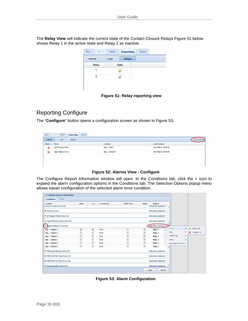
The Relay View will indicate the current state of the Contact Closure Relays Figure 51 below shows Relay 1 in the active state and Relay 2 as inactive.
Reporting Configure The “Configure” button opens a configuration screen as shown in Figure 53.
The Configure Report Information window will open. In the Conditions tab, click the + icon to expand the alarm configuration options in the Conditions tab. The Selection Options popup menu allows easier configuration of the selected alarm error condition.
Figure 53: Alarm Configuration
Figure 52: Alarms View - Configure
Figure 51: Relay reporting view

User Guide
Page 40 (69)
The Error drop down menu is shown in Figure 54. Each condition can be configured as an error or information situation under log severity. The Alarm Relay can also be assigned and set for Relay 1 or Relay 2. When the Relay is enabled the error will trip the respective Relay at the Alarm Contact Closure connector.
Figure 54: Alarm Error Configuration
User Guide
Page 41 (69)
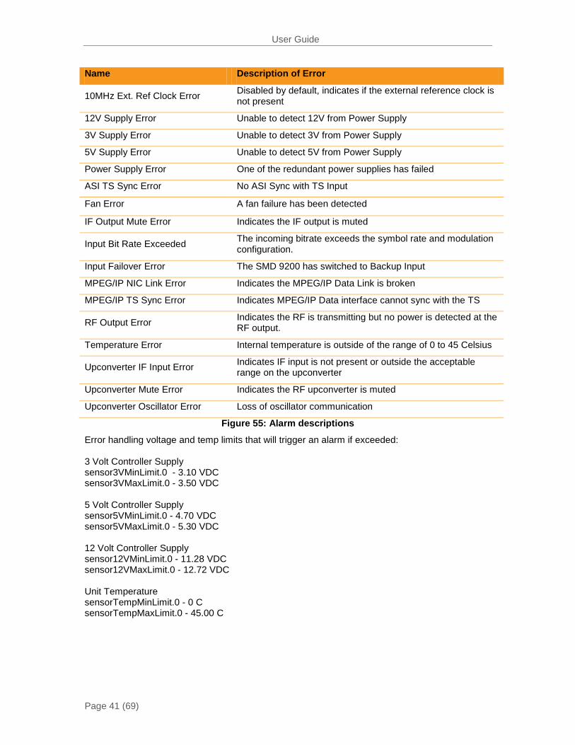
Name Description of Error
10MHz Ext. Ref Clock Error Disabled by default, indicates if the external reference clock is not present
12V Supply Error Unable to detect 12V from Power Supply
3V Supply Error Unable to detect 3V from Power Supply
5V Supply Error Unable to detect 5V from Power Supply
Power Supply Error One of the redundant power supplies has failed
ASI TS Sync Error No ASI Sync with TS Input
Fan Error A fan failure has been detected
IF Output Mute Error Indicates the IF output is muted
Input Bit Rate Exceeded The incoming bitrate exceeds the symbol rate and modulation configuration.
Input Failover Error The SMD 9200 has switched to Backup Input
MPEG/IP NIC Link Error Indicates the MPEG/IP Data Link is broken
MPEG/IP TS Sync Error Indicates MPEG/IP Data interface cannot sync with the TS
RF Output Error Indicates the RF is transmitting but no power is detected at the RF output.
Temperature Error Internal temperature is outside of the range of 0 to 45 Celsius
Upconverter IF Input Error Indicates IF input is not present or outside the acceptable range on the upconverter
Upconverter Mute Error Indicates the RF upconverter is muted
Upconverter Oscillator Error Loss of oscillator communication
Figure 55: Alarm descriptions
Error handling voltage and temp limits that will trigger an alarm if exceeded: 3 Volt Controller Supply sensor3VMinLimit.0 - 3.10 VDC sensor3VMaxLimit.0 - 3.50 VDC 5 Volt Controller Supply sensor5VMinLimit.0 - 4.70 VDC sensor5VMaxLimit.0 - 5.30 VDC 12 Volt Controller Supply sensor12VMinLimit.0 - 11.28 VDC sensor12VMaxLimit.0 - 12.72 VDC Unit Temperature sensorTempMinLimit.0 - 0 C sensorTempMaxLimit.0 - 45.00 C

User Guide
Page 42 (69)
The Events tab allows the setup of Events reporting and actions. Events are notable status changes in the SMD 9200. Click the + icon to expand the event configuration options. The Selection Options popup menu allows easier configuration of the selected event. Refer to Figure 57 Event Descriptions.
Name Description of Event
10MHz Ext. Ref Clock Change Indicates the external reference clock was not present
Date/Time Change The unit’s date/time has been changed
NTP Update The unit’s date/time was updated by the NTP server
Unit Bootup The unit has been loaded
Unit Shutdown The unit was shutdown
Figure 57: Event descriptions
Figure 56: Event Configuration
User Guide
Page 43 (69)
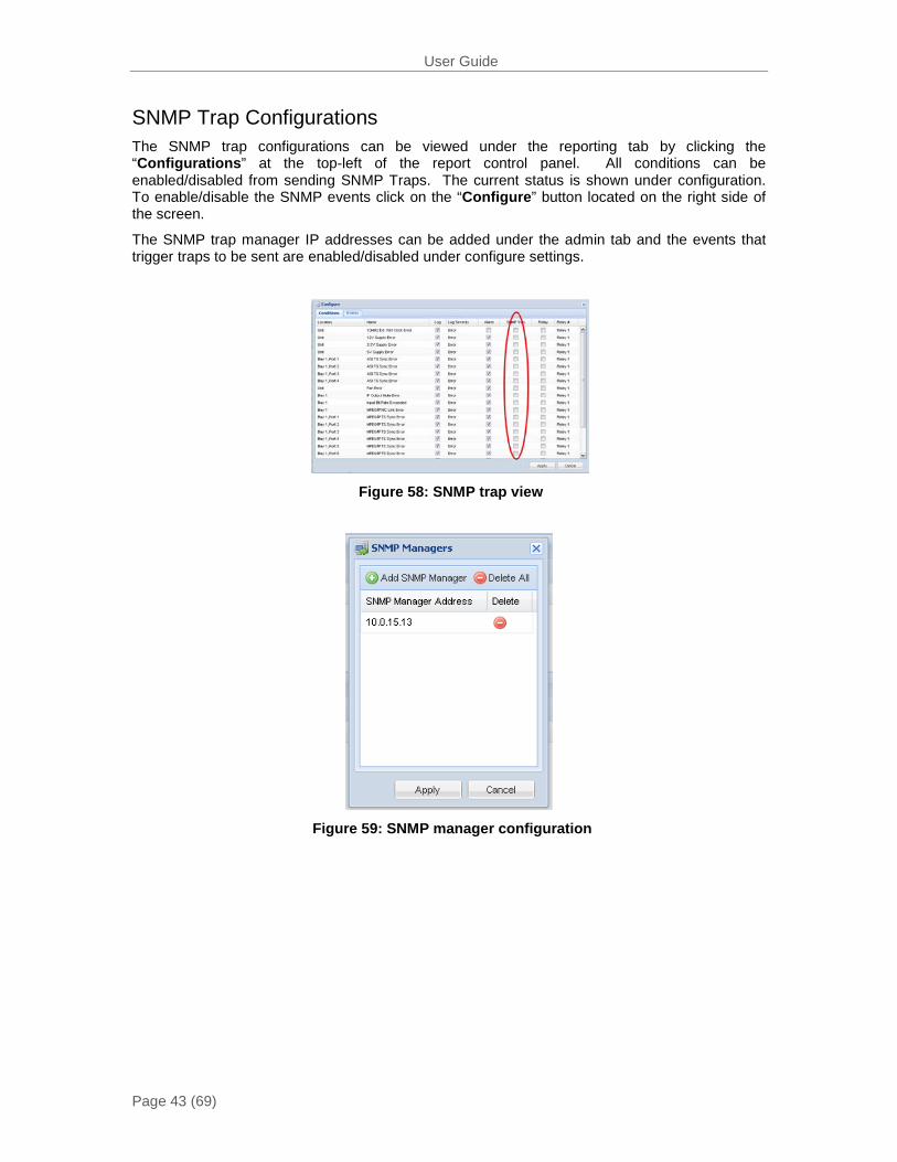
SNMP Trap Configurations The SNMP trap configurations can be viewed under the reporting tab by clicking the “Configurations” at the top-left of the report control panel. All conditions can be enabled/disabled from sending SNMP Traps. The current status is shown under configuration. To enable/disable the SNMP events click on the “Configure” button located on the right side of the screen.
The SNMP trap manager IP addresses can be added under the admin tab and the events that trigger traps to be sent are enabled/disabled under configure settings.
Figure 58: SNMP trap view
Figure 59: SNMP manager configuration

User Guide
Page 44 (69)
Name Description of Trap
10MHz Ext. Ref Clock Error Indicates the unit’s external reference source has changed between either internal or external.
12V Supply Error Unable to detect 12V from Power Supply
3V Supply Error Unable to detect 3V from Power Supply
5V Supply Error Unable to detect 5V from Power Supply
ASI TS Sync Error No ASI Sync with TS Input
Fan Error A fan failure has been detected
IF Output Mute Error Indicates the IF output is muted
Input Bit Rate Exceeded The incoming bitrate exceeds the symbol rate and modulation configuration.
Input Failover Error The Primary input has failed and has switched to backup.
MPEG/IP NIC Link Error Indicates the MPEG/IP Data Link is broken
MPEG/IP TS Sync Error Indicates MPEG/IP Data interface cannot sync with the TS
RF Output Error Indicates the RF is transmitting but no power is detected at the RF output.
Temperature Error Internal temperature is outside of the range of 0 to 45 Celsius
Upconverter IF Input Error Indicates IF input is not present or outside the acceptable range on the upconverter
Upconverter Mute Error Indicates the RF upconverter is muted
Upconverter Oscillator Error Loss of oscillator communication
Figure 60: SNMP trap descriptions
User Guide
Page 45 (69)
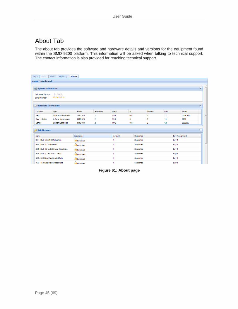
About Tab The about tab provides the software and hardware details and versions for the equipment found within the SMD 9200 platform. This information will be asked when talking to technical support. The contact information is also provided for reaching technical support.
Figure 61: About page
User Guide
Page 46 (69)
BAY 1: MODULATOR SETTINGS↕↵ >INPUT CONFIGURATION MODULATION CONFIGURATION OUTPUT CONFIGURATION
MAIN MENU ↕↵ >BAY 1: MODULATOR SETTINGS ADMIN REPORTING ABOUT
BAY 1 ↔↕↵
40.000 MSPS 2 STREAMS S2 CCM RF: 1450.000 MHZ
2 ERRORS
Bay1:Modulator Bay2:Modulat↔↕↵ 40.000 MSps 20.000 MSps 4Streams S2CCM4Streams S2VCM RF:1450.00 MHz RF:2150.00 MHz
4 Errors
Controlling the SMD 9200 Using the Front Panel
This section of the user manual covers the menus and operation of the SMD9200 platform using the front panel for control. All functionality of the front panel is also capable through the Web User Interface.
FP Modulator Settings
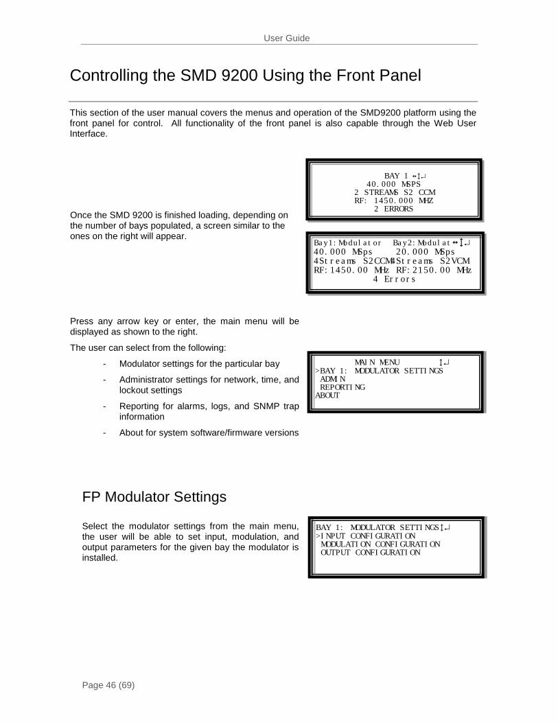
Select the modulator settings from the main menu, the user will be able to set input, modulation, and output parameters for the given bay the modulator is installed.
Once the SMD 9200 is finished loading, depending on the number of bays populated, a screen similar to the ones on the right will appear.
Press any arrow key or enter, the main menu will be displayed as shown to the right.
The user can select from the following:
- Modulator settings for the particular bay
- Administrator settings for network, time, and lockout settings
- Reporting for alarms, logs, and SNMP trap information
- About for system software/firmware versions
User Guide
Page 47 (69)
BAY 1: INPUT CONFIGURATION↕↵ >ASI 1: ALIAS NAME ASI 2: TEST ASI 3: NOT USED IP 1: LIVE INPUT IP 2:BACKUP INPUT
INPUT STATUS: BAY 1: ASI 1↕↵ >PORT: ENABLED ALIAS: ALIAS NAME SYNC: SYNCHRONIZED PACKET SIZE: 188-BYTE BITRATE: 19.392 MBPS
INPUT STATUS: BAY 1: IP 1 ↕↵ >RECEIVE: ENABLED ALIAS: LIVE INPUT ROUTING: MULTICAST ADDRESS: 237.0.0.10 DESTINATION PORT: 1234
INPUT STATUS: BAY 1: IP 1 ↕↵ >TS PACKETS / IP PACKETS: 7 SYNC: SYNCHRONIZED BIT RATE: 10.486 MBPS BUFFER: 1000 KB DISPLAY DELAY:84 MS
Modulator Input Configuration
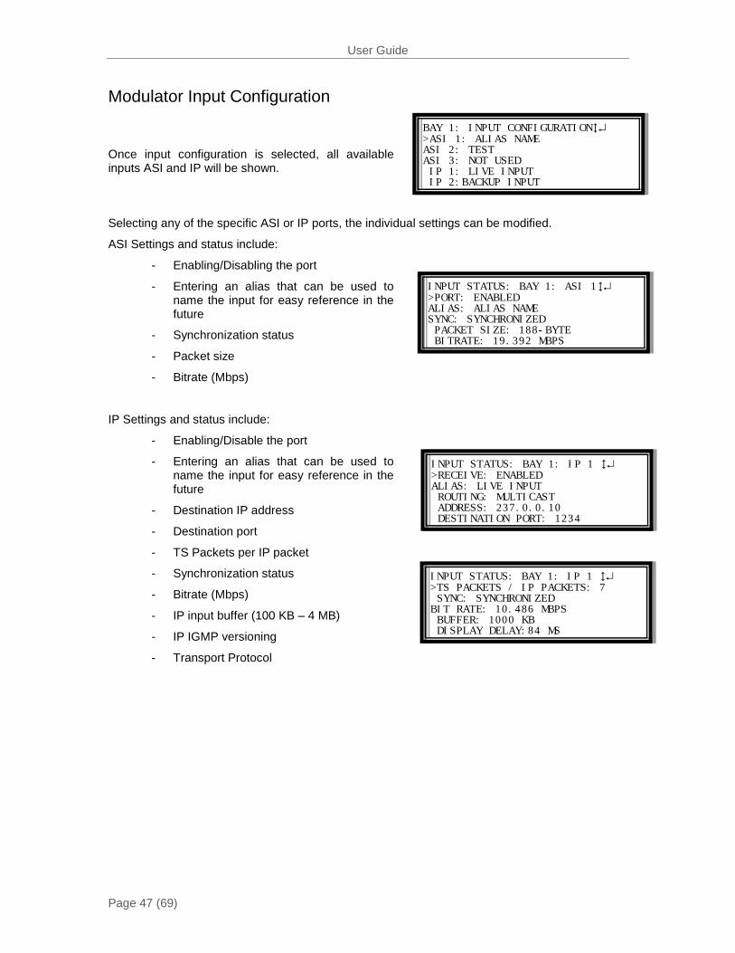
Once input configuration is selected, all available inputs ASI and IP will be shown.
Selecting any of the specific ASI or IP ports, the individual settings can be modified.
ASI Settings and status include:
- Enabling/Disabling the port
- Entering an alias that can be used to name the input for easy reference in the future
- Synchronization status
- Packet size
- Bitrate (Mbps)
IP Settings and status include:
- Enabling/Disable the port
- Entering an alias that can be used to name the input for easy reference in the future
- Destination IP address
- Destination port
- TS Packets per IP packet
- Synchronization status
- Bitrate (Mbps)
- IP input buffer (100 KB – 4 MB)
- IP IGMP versioning
- Transport Protocol
User Guide
Page 48 (69)
BAY 1: MODULATOR CONFIGURAT ↕↵ MODULATION PARAMETERS >MODULATION MODE: S2 MULTI-CCM
BAY 1: MODULATOR MODULATION ↕↵ >SYMBOL RATE: 38.000000 MSPS MINIMUM: 16.455536 MSPS MODULATION/FEC 8PSK 2/3 PILOT INSERTION: ENABLED FRAME SIZE: NORMAL
BAY 1: MODULATOR MODULATION ↕↵ >PILOT INSERTION: ENABLED FRAME SIZE: NORMAL SPECTRAL INVERSION: NORMAL ALPHA FILTER ROLLOFF: 0.35 CARRIER WAVE: DISABLED
BAY 1: MODULATOR PARAMETER ↕↵ >GLOBAL SETTINGS STREAM 1: ASI1 ALIAS NAME STREAM 2: ASI2 TEST STREAM 3: IP1 LIVE STREAM 4: IP2 BACKUP
BAY 1: MODULATOR MODULATION ↕↵ >SWITCH TO BACKUP INPUT FAILOVER: PRIMARY TS SYNC LOSS RESTORE: MANUAL ONLY SWITCHOVER: 05 SEC SYMBOL RATE: 38.000000 MSPS
BAY 1: MODULATOR MODULATION ↕↵ >PRIMARY INPUT: ASI1 BACKUP INPUT: IP1 ACTIVE INPUT: ASI1 (PRIMARY) SWITCH TO BACKUP INPUT
Modulator Modulation Configuration
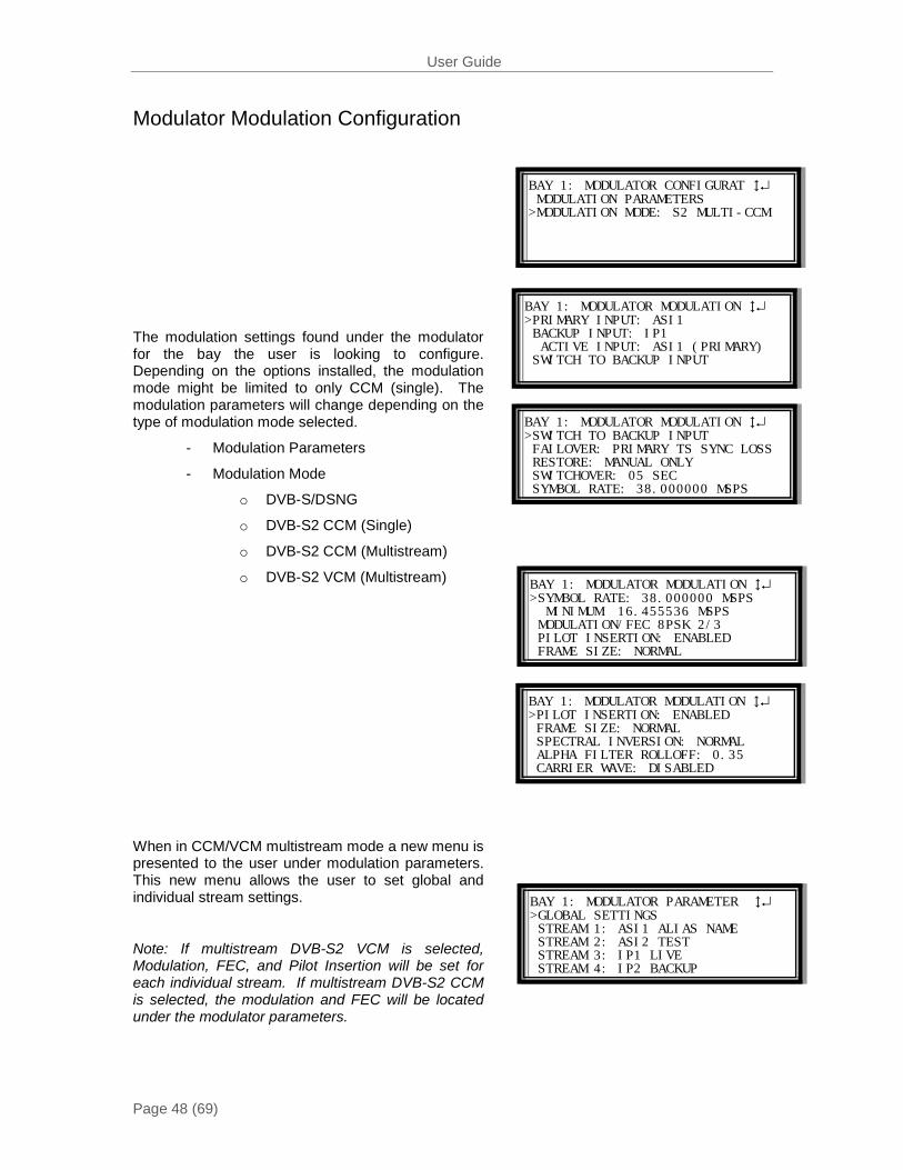
The modulation settings found under the modulator for the bay the user is looking to configure. Depending on the options installed, the modulation mode might be limited to only CCM (single). The modulation parameters will change depending on the type of modulation mode selected.
- Modulation Parameters
- Modulation Mode
o DVB-S/DSNG
o DVB-S2 CCM (Single)
o DVB-S2 CCM (Multistream)
o DVB-S2 VCM (Multistream)
When in CCM/VCM multistream mode a new menu is presented to the user under modulation parameters. This new menu allows the user to set global and individual stream settings.
Note: If multistream DVB-S2 VCM is selected, Modulation, FEC, and Pilot Insertion will be set for each individual stream. If multistream DVB-S2 CCM is selected, the modulation and FEC will be located under the modulator parameters.
User Guide
Page 49 (69)
GLOBAL SETTINGS ↕↵ >SYMBOL RATE: 20.014553 MSPS MINIMUM: 16.45536 MSPS FRAME SIZE: NORMAL SPECTRAL INVERSION: NORMAL
GLOBAL SETTINGS ↕↵ FRAME SIZE: NORMAL SPECTRAL INVERSION: NORMAL ALPHA FILTER ROLLOFF: 0.35 >CARRIER WAVE: DISABLED
MODULATION: BAY 1: STREAM 1 ↕↵ >INPUT: ASI1 UNIT ALIAS MODULATOIN/FEC: 8PSK 2/3 PILOT INSERTION: ENABLED ISI: 002
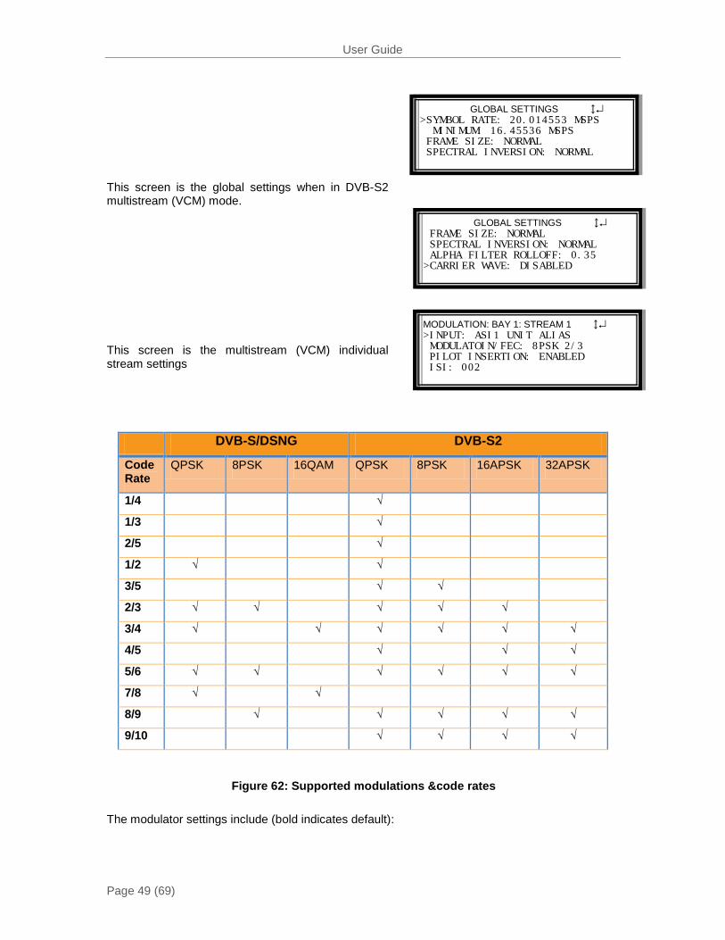
This screen is the global settings when in DVB-S2 multistream (VCM) mode.
This screen is the multistream (VCM) individual stream settings
DVB-S/DSNG DVB-S2
Code Rate
QPSK 8PSK 16QAM QPSK 8PSK 16APSK 32APSK
1/4 √
1/3 √
2/5 √
1/2 √ √
3/5 √ √
2/3 √ √ √ √ √
3/4 √ √ √ √ √ √
4/5 √ √ √
5/6 √ √ √ √ √ √
7/8 √ √
8/9 √ √ √ √ √
9/10 √ √ √ √
The modulator settings include (bold indicates default):
Figure 62: Supported modulations &code rates
User Guide
Page 50 (69)
Pilot Insertion(Only available in DVB-S2 Modes) - Enable
- Disable
Description: When enabled, every 16 slots of 90 symbols the modulator will insert 36 non-modulated symbols to aid in receiver synchronization. The use of pilots will allow the receiver to maintain carrier recovery, even when the user data payload cannot be decoded.
Frame Size(Only available in DVB-S2 Modes) - Normal (64,800 bits)
- Short (16,200 bits)
Description: Short frames introduce more overhead but give a shorter encapsulation delay. Short frames are 4 time shorter than normal frames.
Spectral Inversion - Normal
- Inverted
Description: Determines whether the spectrum is inverted or normal. Note: When the SMD 920H L-Band option is installed, the default spectral inversion is inverted as the upconverter is set to invert. Setting the output to Inverted will give a normal output from the upconverter.
Alpha Filter Rolloff - 0.35
- 0.25
- 0.20
Description: The filter rolloff is known as the alpha coefficient (α). The smaller the α, the less bandwidth will be required on the satellite.
Carrier Wave - Disabled
- Enabled
Description: This is used for calibration and verification of spectrum polarity.
User Guide
Page 51 (69)
BAY 1: IF OUTPUT↕↵ >OUTPUT: ACTIVE FREQUENCY: 70 MHZ LEVEL: -10 DBM TILT: +0.0 DB
BAY 1: RF OUTPUT↕↵ >OUTPUT: ACTIVE FREQUENCY: 1450.000 MHZ 10 MHZ REF. CLOCK : ENABLED BUC POWER : ENABLED IF INPUT STATUS: OK
BAY 1: RF OUTPUT↕↵ >LEVEL: -10.0 DBM IF INPUT STATUS: HIGH OUTPUT STATUS: PRESENT OSCILLATOR STATUS: LOCKED
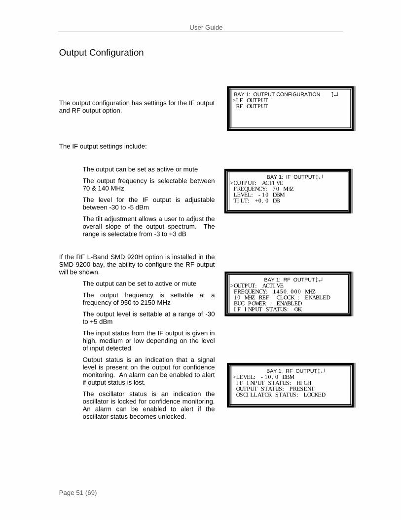
BAY 1: OUTPUT CONFIGURATION ↕↵ >IF OUTPUT RF OUTPUT
Output Configuration
The IF output settings include:
The output can be set as active or mute
The output frequency is selectable between 70 & 140 MHz
The level for the IF output is adjustable between -30 to -5 dBm
The tilt adjustment allows a user to adjust the overall slope of the output spectrum. The range is selectable from -3 to +3 dB
If the RF L-Band SMD 920H option is installed in the SMD 9200 bay, the ability to configure the RF output will be shown.
The output can be set to active or mute
The output frequency is settable at a frequency of 950 to 2150 MHz
The output level is settable at a range of -30 to +5 dBm
The input status from the IF output is given in high, medium or low depending on the level of input detected.
Output status is an indication that a signal level is present on the output for confidence monitoring. An alarm can be enabled to alert if output status is lost.
The oscillator status is an indication the oscillator is locked for confidence monitoring. An alarm can be enabled to alert if the oscillator status becomes unlocked.
The output configuration has settings for the IF output and RF output option.
User Guide
Page 52 (69)
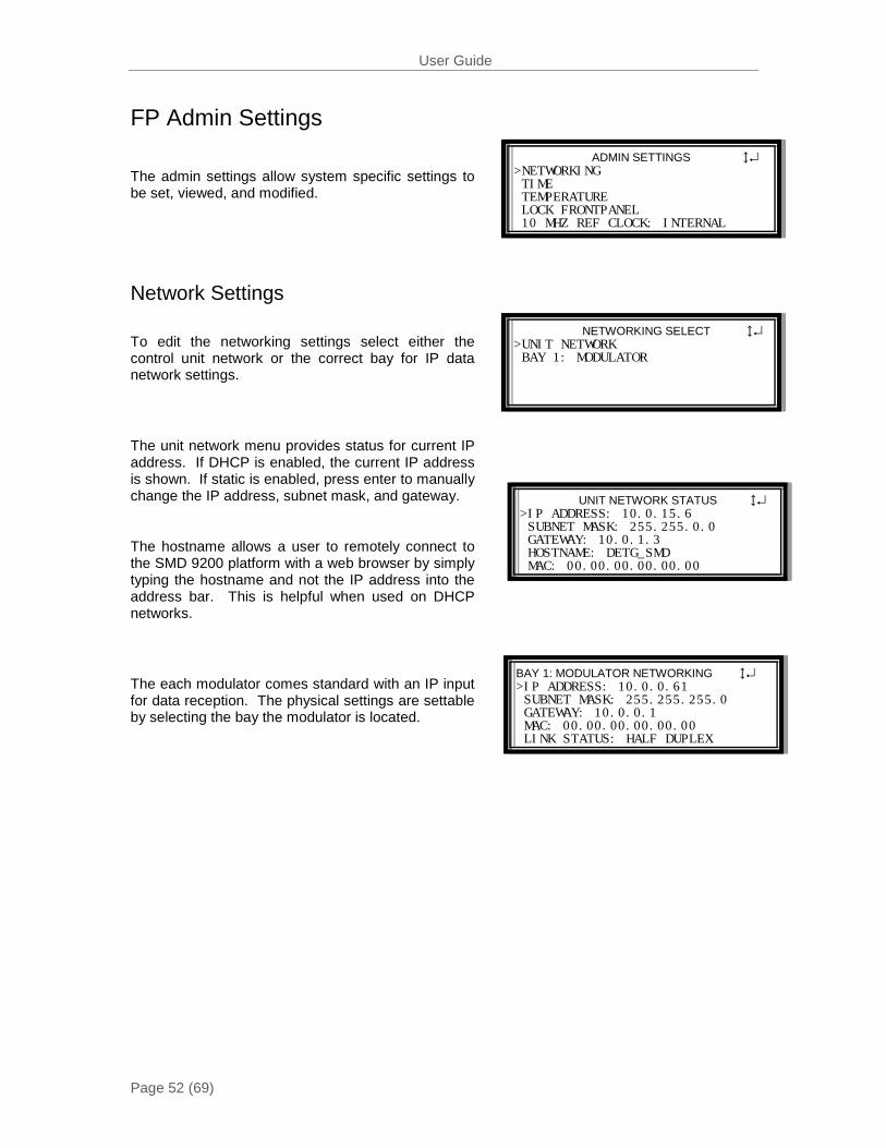
ADMIN SETTINGS ↕↵ >NETWORKING TIME TEMPERATURE LOCK FRONTPANEL 10 MHZ REF CLOCK: INTERNAL
NETWORKING SELECT ↕↵ >UNIT NETWORK BAY 1: MODULATOR
UNIT NETWORK STATUS ↕↵ >IP ADDRESS: 10.0.15.6 SUBNET MASK: 255.255.0.0 GATEWAY: 10.0.1.3 HOSTNAME: DETG_SMD MAC: 00.00.00.00.00.00
BAY 1: MODULATOR NETWORKING ↕↵ >IP ADDRESS: 10.0.0.61 SUBNET MASK: 255.255.255.0 GATEWAY: 10.0.0.1 MAC: 00.00.00.00.00.00 LINK STATUS: HALF DUPLEX
FP Admin Settings
The admin settings allow system specific settings to be set, viewed, and modified.
Network Settings
To edit the networking settings select either the control unit network or the correct bay for IP data network settings.
The unit network menu provides status for current IP address. If DHCP is enabled, the current IP address is shown. If static is enabled, press enter to manually change the IP address, subnet mask, and gateway.
The hostname allows a user to remotely connect to the SMD 9200 platform with a web browser by simply typing the hostname and not the IP address into the address bar. This is helpful when used on DHCP networks.
The each modulator comes standard with an IP input for data reception. The physical settings are settable by selecting the bay the modulator is located.
User Guide
Page 53 (69)
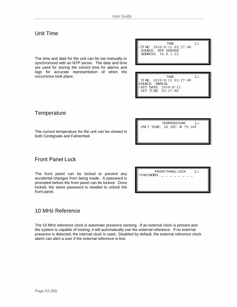
TIME ↕↵ >TIME: 2010/8/12 03:27:48 SOURCE: NTP SERVER ADDRESS: 10.0.1.23
TIME ↕↵ TIME: 2010/8/12 03:27:48 SOURCE: MANUAL >SET DATE: 2010/8/12 SET TIME: 03:27:48
TEMPERATURE ↕↵ UNIT TEMP: 26.39C 79.50F
FRONT PANEL LOCK ↕↵ >PASSWORD: _ _ _ _ _ _ _ _
Unit Time
The time and date for the unit can be set manually or synchronized with an NTP server. The date and time are used for storing the correct time for alarms and logs for accurate representation of when the occurrence took place.
Temperature
The current temperature for the unit can be viewed in both Centigrade and Fahrenheit.
Front Panel Lock
The front panel can be locked to prevent any accidental changes from being made. A password is prompted before the front panel can be locked. Once locked, the same password is needed to unlock the front panel.
10 MHz Reference
The 10 MHz reference clock is automatic presence sensing. If an external clock is present and the system is capable of locking, it will automatically use the external reference. If no external presence is detected, the internal clock is used. Disabled by default, the external reference clock alarm can alert a user if the external reference is lost.
User Guide
Page 54 (69)
REPORTING ↕↵ >ACTIVE ALARMS (1) CONDITION CONFIGURATION EVENT LOGS (142) EVENT CONFIGURATION
ACTIVE ALARMS ↔↵ >ASI TS SYNC ERROR – LOC: BAY 1,
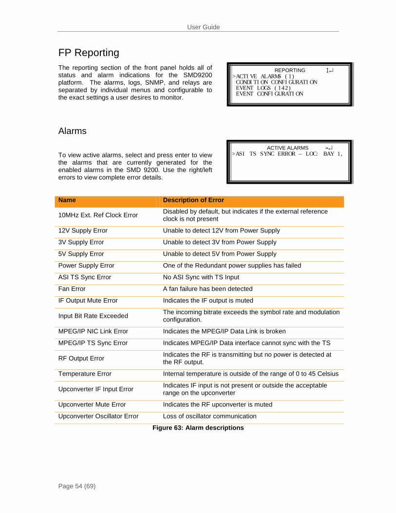
FP Reporting The reporting section of the front panel holds all of status and alarm indications for the SMD9200 platform. The alarms, logs, SNMP, and relays are separated by individual menus and configurable to the exact settings a user desires to monitor.
Alarms
To view active alarms, select and press enter to view the alarms that are currently generated for the enabled alarms in the SMD 9200. Use the right/left errors to view complete error details.
Name Description of Error
10MHz Ext. Ref Clock Error Disabled by default, but indicates if the external reference clock is not present
12V Supply Error Unable to detect 12V from Power Supply
3V Supply Error Unable to detect 3V from Power Supply
5V Supply Error Unable to detect 5V from Power Supply
Power Supply Error One of the Redundant power supplies has failed
ASI TS Sync Error No ASI Sync with TS Input
Fan Error A fan failure has been detected
IF Output Mute Error Indicates the IF output is muted
Input Bit Rate Exceeded The incoming bitrate exceeds the symbol rate and modulation configuration.
MPEG/IP NIC Link Error Indicates the MPEG/IP Data Link is broken
MPEG/IP TS Sync Error Indicates MPEG/IP Data interface cannot sync with the TS
RF Output Error Indicates the RF is transmitting but no power is detected at the RF output.
Temperature Error Internal temperature is outside of the range of 0 to 45 Celsius
Upconverter IF Input Error Indicates IF input is not present or outside the acceptable range on the upconverter
Upconverter Mute Error Indicates the RF upconverter is muted
Upconverter Oscillator Error Loss of oscillator communication
Figure 63: Alarm descriptions
User Guide
Page 55 (69)
Error handling voltage and temp limits that will trigger an alarm if exceeded: 3 Volt Controller Supply sensor3VMinLimit.0 - 3.10 VDC sensor3VMaxLimit.0 - 3.50 VDC 5 Volt Controller Supply sensor5VMinLimit.0 - 4.70 VDC sensor5VMaxLimit.0 - 5.30 VDC 12 Volt Controller Supply sensor12VMinLimit.0 - 11.28 VDC sensor12VMaxLimit.0 - 12.72 VDC Unit Temperature sensorTempMinLimit.0 - 0 C sensorTempMaxLimit.0 - 45.00 C
User Guide
Page 56 (69)
CONDITION SELECT ↕↵ >FAN ERROR - UNIT 3V SUPPLY ERROR - UNIT 5V SUPPLY ERROR - UNIT 12V SUPPLY ERROR – UNIT ASI TS SYNC ERROR – BAY 1
FAN ERROR ↕↵ >LOGGING: ENABLED SNMP TRAP: DISABLED RELAY: RELAY 1 RELAY ACTIVATION: DISABLED ALARM NOTIFICATION: ENABLED
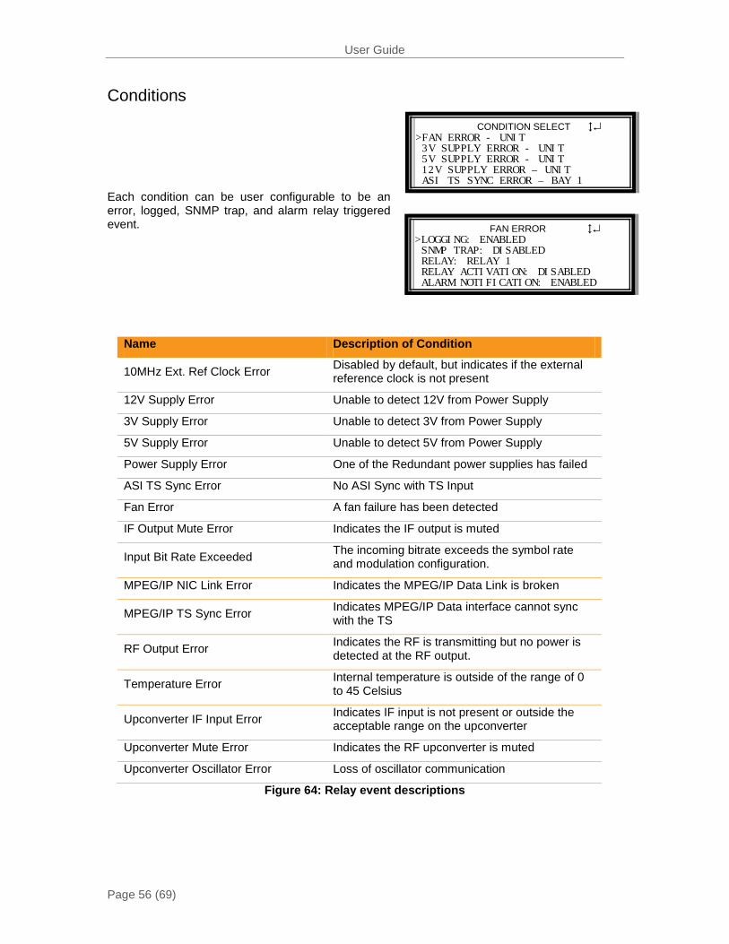
Conditions
Each condition can be user configurable to be an error, logged, SNMP trap, and alarm relay triggered event.
Name Description of Condition
10MHz Ext. Ref Clock Error Disabled by default, but indicates if the external reference clock is not present
12V Supply Error Unable to detect 12V from Power Supply
3V Supply Error Unable to detect 3V from Power Supply
5V Supply Error Unable to detect 5V from Power Supply
Power Supply Error One of the Redundant power supplies has failed
ASI TS Sync Error No ASI Sync with TS Input
Fan Error A fan failure has been detected
IF Output Mute Error Indicates the IF output is muted
Input Bit Rate Exceeded The incoming bitrate exceeds the symbol rate and modulation configuration.
MPEG/IP NIC Link Error Indicates the MPEG/IP Data Link is broken
MPEG/IP TS Sync Error Indicates MPEG/IP Data interface cannot sync with the TS
RF Output Error Indicates the RF is transmitting but no power is detected at the RF output.
Temperature Error Internal temperature is outside of the range of 0 to 45 Celsius
Upconverter IF Input Error Indicates IF input is not present or outside the acceptable range on the upconverter
Upconverter Mute Error Indicates the RF upconverter is muted
Upconverter Oscillator Error Loss of oscillator communication
Figure 64: Relay event descriptions
User Guide
Page 57 (69)
EVENT SELECT ↕↵ >DATE/TIME CHANGE – UNIT UNIT BOTUP – UNIT UNIT SHUTDOWN – UNIT 10 MHZ REFERENCE CHANGE – UNIT NTP UPDATE - UNIT
DATE/TIME CHANGE ↕↵ >LOGGING: ENABLED SNMP TRAP: DISABLED RELAY: RELAY 1 RELAY ACTIVATION: DISABLED REALY DURATION: 0100 MS
EVENT LOGS ↔↕↵ >130 2010/08/25 UNIT BOOTED 129 2010/08/25 IF OUTPUT: NOTM 128 2010/08/25 IF OUTPUT: MUTED 127 2010/08/25 ASI TS: ABSENT
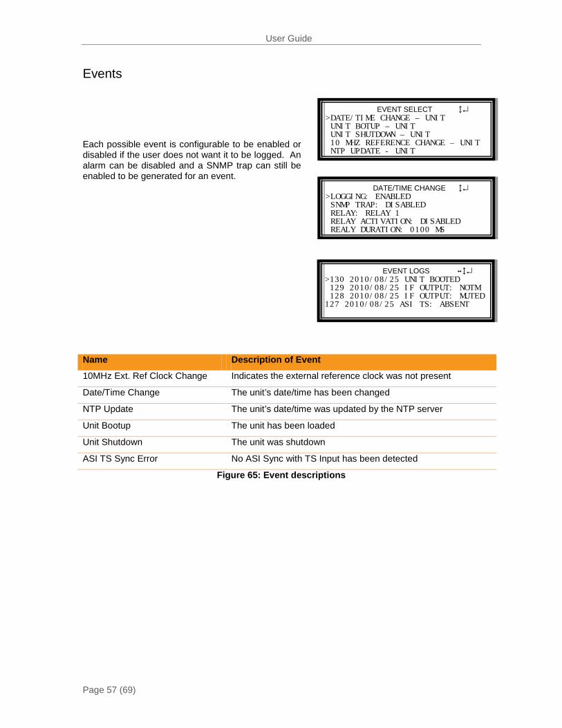
Events
Each possible event is configurable to be enabled or disabled if the user does not want it to be logged. An alarm can be disabled and a SNMP trap can still be enabled to be generated for an event.
Name Description of Event
10MHz Ext. Ref Clock Change Indicates the external reference clock was not present
Date/Time Change The unit’s date/time has been changed
NTP Update The unit’s date/time was updated by the NTP server
Unit Bootup The unit has been loaded
Unit Shutdown The unit was shutdown
ASI TS Sync Error No ASI Sync with TS Input has been detected
Figure 65: Event descriptions
User Guide
Page 58 (69)
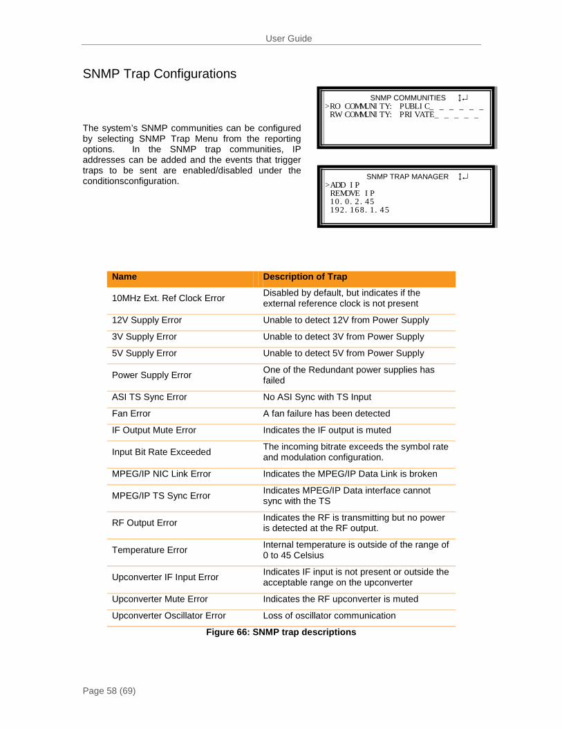
SNMP COMMUNITIES ↕↵ >RO COMMUNITY: PUBLIC_ _ _ _ _ _ RW COMMUNITY: PRIVATE_ _ _ _ _
SNMP TRAP MANAGER ↕↵ >ADD IP REMOVE IP 10.0.2.45 192.168.1.45
SNMP Trap Configurations
The system’s SNMP communities can be configured by selecting SNMP Trap Menu from the reporting options. In the SNMP trap communities, IP addresses can be added and the events that trigger traps to be sent are enabled/disabled under the conditionsconfiguration.
Name Description of Trap
10MHz Ext. Ref Clock Error Disabled by default, but indicates if the external reference clock is not present
12V Supply Error Unable to detect 12V from Power Supply
3V Supply Error Unable to detect 3V from Power Supply
5V Supply Error Unable to detect 5V from Power Supply
Power Supply Error One of the Redundant power supplies has failed
ASI TS Sync Error No ASI Sync with TS Input
Fan Error A fan failure has been detected
IF Output Mute Error Indicates the IF output is muted
Input Bit Rate Exceeded The incoming bitrate exceeds the symbol rate and modulation configuration.
MPEG/IP NIC Link Error Indicates the MPEG/IP Data Link is broken
MPEG/IP TS Sync Error Indicates MPEG/IP Data interface cannot sync with the TS
RF Output Error Indicates the RF is transmitting but no power is detected at the RF output.
Temperature Error Internal temperature is outside of the range of 0 to 45 Celsius
Upconverter IF Input Error Indicates IF input is not present or outside the acceptable range on the upconverter
Upconverter Mute Error Indicates the RF upconverter is muted
Upconverter Oscillator Error Loss of oscillator communication
Figure 66: SNMP trap descriptions
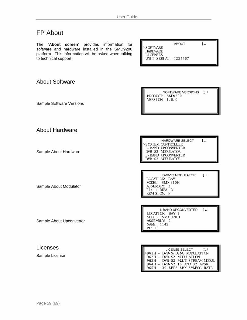
User Guide
Page 59 (69)
ABOUT ↕↵ >SOFTWARE HARDWARE LICENSES UNIT SERIAL: 1234567
SOFTWARE VERSIONS ↕↵ PRODUCT: SMD9200 VERSION: 1.0.0
HARDWARE SELECT ↕↵ >SYSTEM CONTROLLER L-BAND UPCONVERTER DVB-S2 MODULATOR L-BAND UPCONVERTER DVB-S2 MODULATOR
DVB-S2 MODULATOR ↕↵ LOCATION: BAY 1 MODEL: SMD 910H ASSEMBLY: 2 PI: 1 REV: D REVISION: F
L-BAND UPCONVERTER ↕↵ LOCATION: BAY 1 MODEL: SMD 920H ASSEMBLY: 2 NAME: 1143 PI: 0
LICENSE SELECT ↕↵ >961H – DVB-S/DSNG MODULATION 962H – DVB-S2 MODULATION 963H – DVB=S2 MULTISTREAM MODUL 964H – DVB-S2 16 AND 32 APSK 965H – 30 MBPS MAX SYMBOL RATE
FP About
The “About screen” provides information for software and hardware installed in the SMD9200 platform. This information will be asked when talking to technical support.
About Software
Sample Software Versions
About Hardware
Sample About Hardware
Sample About Modulator
Sample About Upconverter
Licenses Sample License
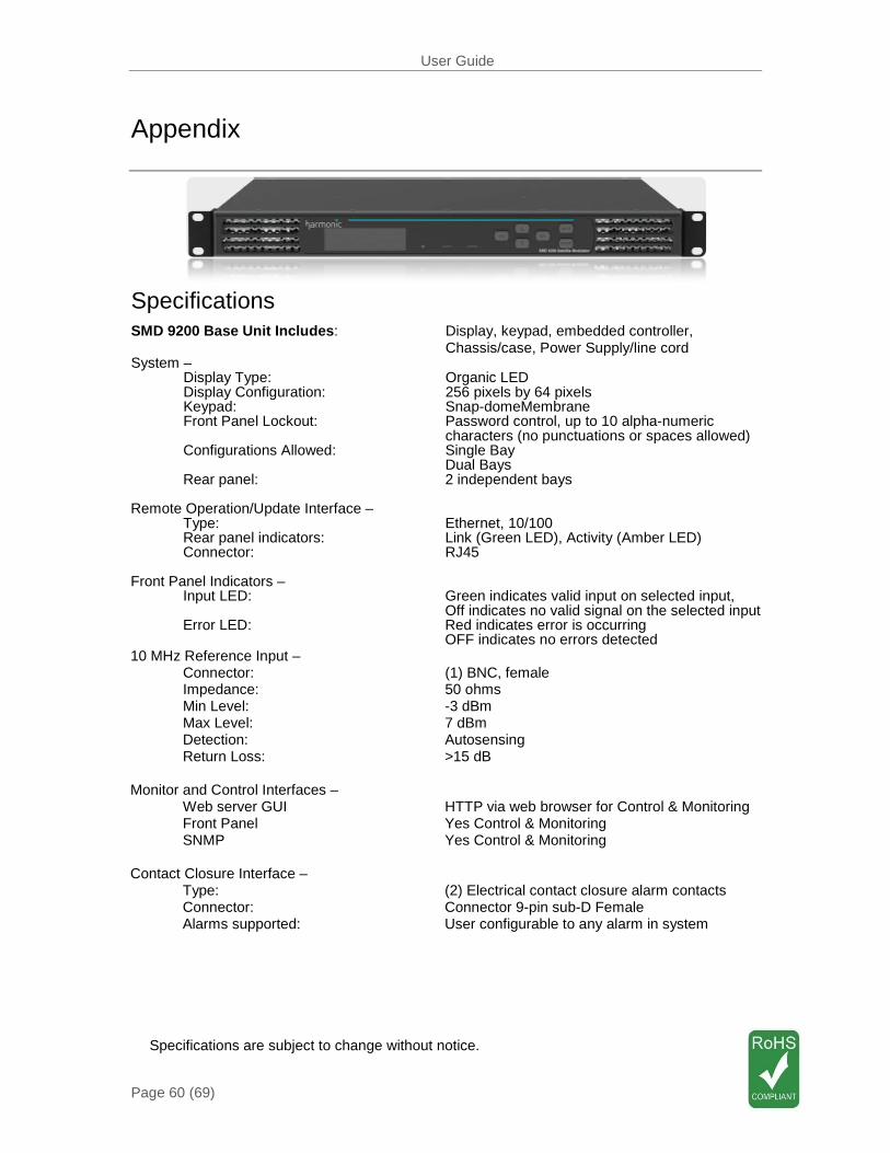
User Guide
Page 60 (69)
Appendix
Specifications SMD 9200 Base Unit Includes: Display, keypad, embedded controller, Chassis/case, Power Supply/line cord System – Display Type: Organic LED Display Configuration: 256 pixels by 64 pixels Keypad: Snap-domeMembrane Front Panel Lockout: Password control, up to 10 alpha-numeric characters (no punctuations or spaces allowed) Configurations Allowed: Single Bay Dual Bays Rear panel: 2 independent bays Remote Operation/Update Interface – Type: Ethernet, 10/100 Rear panel indicators: Link (Green LED), Activity (Amber LED) Connector: RJ45 Front Panel Indicators – Input LED: Green indicates valid input on selected input, Off indicates no valid signal on the selected input Error LED: Red indicates error is occurring OFF indicates no errors detected 10 MHz Reference Input – Connector: (1) BNC, female Impedance: 50 ohms Min Level: -3 dBm Max Level: 7 dBm Detection: Autosensing Return Loss: >15 dB Monitor and Control Interfaces – Web server GUI HTTP via web browser for Control & Monitoring Front Panel Yes Control & Monitoring SNMP Yes Control & Monitoring Contact Closure Interface – Type: (2) Electrical contact closure alarm contacts Connector: Connector 9-pin sub-D Female Alarms supported: User configurable to any alarm in system
Specifications are subject to change without notice.
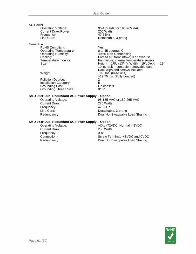
User Guide
Page 61 (69)
AC Power – Operating Voltage: 95-135 VAC or 180-265 VAC Current Draw/Power: 200 Watts Frequency: 47-63Hz Line Cord: Detachable, 3-prong General – RoHS Compliant: Yes Operating Temperature: 0 to 45 degrees C Operating Humidity: <95% Non-Condensing Cooling: Forced air, front intake, rear exhaust Temperature monitor: Fan failure, internal temperature sensor Size: Height = 1RU (13/4”), Width = 19”, Depth = 19” 19 in. rack mountable, removable ears Rack clips and screws included Weight: ~9.5 lbs. (base unit) ~12.75 lbs. (Fully Loaded) Pollution Degree: 2 Installation Category: II Grounding Post: On chassis Grounding Thread Size: 8/32” SMD 952HDual Redundant AC Power Supply – Option Operating Voltage: 95-135 VAC or 180-265 VAC Current Draw: 275 Watts Frequency: 47-63Hz Line Cord: Detachable, 3-prong Redundancy Dual Hot Swappable Load Sharing SMD 954HDual Redundant DC Power Supply – Option Operating Voltage: -40to -72VDC, Normal -48VDC Current Draw: 250 Watts Frequency: 0Hz Connection: Screw Terminal, -48VDC and 0VDC Redundancy Dual Hot Swappable Load Sharing
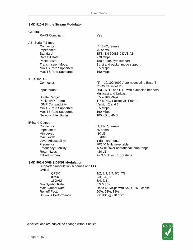
User Guide
Page 62 (69)
SMD 910H Single Stream Modulator General – RoHS Compliant: Yes ASI Serial TS Input – Connector: (4) BNC, female Impedance: 75 ohms Standard: ETSI EN 50083-9 DVB ASI Data Bit Rate: 270 Mbps Packet Size: 188 or 204 byte support Transmission Mode: Burst and packet mode support Min TS Rate Supported: 0.5 Mbps Max TS Rate Supported: 160 Mbps IP TS Input – Connector: (1) – 10/100/1000 Auto-negotiating Base-T RJ-45 Ethernet Port Input format: UDP, RTP, and RTP with extension headers Multicast and Unicast Bitrate Range: 0.5 – 160 Mbps Packets/IP Frame 1-7 MPEG Packets/IP Frame IGMP Compatibility: Version 2 and 3 Min TS Rate Supported: 0.5 Mbps Max TS Rate Supported: 160 Mbps Network Jitter Buffer: 100 KB to 4MB IF-band Output – Connector: (1) BNC, female Impedance: 75 ohms Min Level: -30 dBm Max Level: -5 dBm Level Adjustability: 1 dB increments Frequency: 70/140 MHz selectable Frequency Stability: +/-5x10-8over operational temp range Return Loss: >20 dB Tilt Adjustment: +/- 3.0 dB in 0.1 dB steps SMD 961H DVB-S/DSNG Modulation Supported modulation schemes and FEC: DVB-S QPSK 1/2, 2/3, 3/4, 5/6, 7/8 8PSK 2/3, 5/6, 8/9 16QAM 3/4, 7/8 Min Symbol Rate: 0.5 MSps Max Symbol Rate: Up to 45 MSps with SMD 966 License Roll-off Factor: 20%, 25%, 35% Spurious Performance -50 dBc @ -10 dBm Specifications are subject to change without notice.
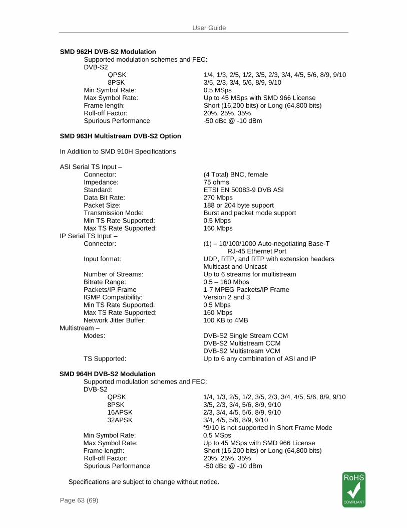
User Guide
Page 63 (69)
SMD 962H DVB-S2 Modulation Supported modulation schemes and FEC: DVB-S2 QPSK 1/4, 1/3, 2/5, 1/2, 3/5, 2/3, 3/4, 4/5, 5/6, 8/9, 9/10 8PSK 3/5, 2/3, 3/4, 5/6, 8/9, 9/10 Min Symbol Rate: 0.5 MSps Max Symbol Rate: Up to 45 MSps with SMD 966 License Frame length: Short (16,200 bits) or Long (64,800 bits) Roll-off Factor: 20%, 25%, 35% Spurious Performance -50 dBc @ -10 dBm SMD 963H Multistream DVB-S2 Option In Addition to SMD 910H Specifications ASI Serial TS Input – Connector: (4 Total) BNC, female Impedance: 75 ohms Standard: ETSI EN 50083-9 DVB ASI Data Bit Rate: 270 Mbps Packet Size: 188 or 204 byte support Transmission Mode: Burst and packet mode support Min TS Rate Supported: 0.5 Mbps Max TS Rate Supported: 160 Mbps IP Serial TS Input – Connector: (1) – 10/100/1000 Auto-negotiating Base-T RJ-45 Ethernet Port Input format: UDP, RTP, and RTP with extension headers Multicast and Unicast Number of Streams: Up to 6 streams for multistream Bitrate Range: 0.5 – 160 Mbps Packets/IP Frame 1-7 MPEG Packets/IP Frame IGMP Compatibility: Version 2 and 3 Min TS Rate Supported: 0.5 Mbps Max TS Rate Supported: 160 Mbps Network Jitter Buffer: 100 KB to 4MB Multistream – Modes: DVB-S2 Single Stream CCM DVB-S2 Multistream CCM DVB-S2 Multistream VCM TS Supported: Up to 6 any combination of ASI and IP SMD 964H DVB-S2 Modulation Supported modulation schemes and FEC: DVB-S2 QPSK 1/4, 1/3, 2/5, 1/2, 3/5, 2/3, 3/4, 4/5, 5/6, 8/9, 9/10 8PSK 3/5, 2/3, 3/4, 5/6, 8/9, 9/10 16APSK 2/3, 3/4, 4/5, 5/6, 8/9, 9/10 32APSK 3/4, 4/5, 5/6, 8/9, 9/10 *9/10 is not supported in Short Frame Mode Min Symbol Rate: 0.5 MSps Max Symbol Rate: Up to 45 MSps with SMD 966 License Frame length: Short (16,200 bits) or Long (64,800 bits) Roll-off Factor: 20%, 25%, 35% Spurious Performance -50 dBc @ -10 dBm
Specifications are subject to change without notice.
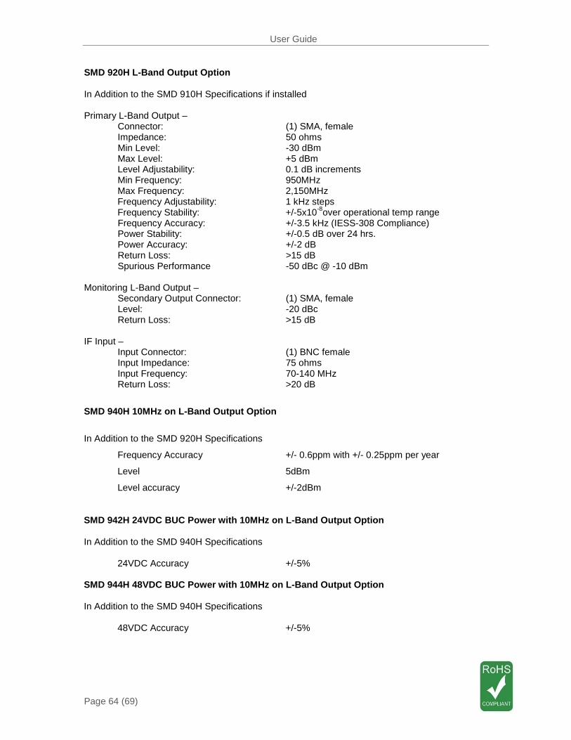
User Guide
Page 64 (69)
SMD 920H L-Band Output Option In Addition to the SMD 910H Specifications if installed Primary L-Band Output – Connector: (1) SMA, female Impedance: 50 ohms
Min Level: -30 dBm Max Level: +5 dBm Level Adjustability: 0.1 dB increments Min Frequency: 950MHz Max Frequency: 2,150MHz Frequency Adjustability: 1 kHz steps Frequency Stability: +/-5x10-8over operational temp range Frequency Accuracy: +/-3.5 kHz (IESS-308 Compliance) Power Stability: +/-0.5 dB over 24 hrs. Power Accuracy: +/-2 dB
Return Loss: >15 dB Spurious Performance -50 dBc @ -10 dBm
Monitoring L-Band Output –
Secondary Output Connector: (1) SMA, female Level: -20 dBc Return Loss: >15 dB
IF Input – Input Connector: (1) BNC female Input Impedance: 75 ohms Input Frequency: 70-140 MHz Return Loss: >20 dB
SMD 940H 10MHz on L-Band Output Option
In Addition to the SMD 920H Specifications
Frequency Accuracy +/- 0.6ppm with +/- 0.25ppm per year
Level 5dBm
Level accuracy +/-2dBm
SMD 942H 24VDC BUC Power with 10MHz on L-Band Output Option In Addition to the SMD 940H Specifications 24VDC Accuracy +/-5% SMD 944H 48VDC BUC Power with 10MHz on L-Band Output Option In Addition to the SMD 940H Specifications 48VDC Accuracy +/-5%

User Guide
Page 65 (69)
Open Source Software
The SMD 9200 includes: Package Version License Copyright
AT32 UC3B Software Framework
1.4.0 BSD 2008, Atmel Corporation
BaseX4JIT 4.0 GPL Version 3, 29 June 2007 2007-2009, Active Group, Inc
BusyBox 1.15.2 GPL Version 2, June 1991 ?
Cgicc 3.2.9 LGPL Version 29, June 2007
Stephen F. Booth
dfu-programmer 0.5.2 GPL Version 2, June 1991 Weston Schmidt
Dropbear 0.52 MIT-like 2002-2008 Matt Johnston, et. Al (see license)
E2fsprogs 1.41.9 GPL Version 2, June 1991 Theodore Ts’o
ethtool 2.6.34 GPL Version 2, June 1991 David Miller, et. al.
FamFamFam Silk Icons 013 Creative Commons Attribution 2.5
Mark James
FastDB 3.59 MIT-like Konstantin Knizhnik
FCGI 2.4.0 FastCGI Open Market, Inc
Iproute2 2.6.29 GPL Version 2, June 1991 Stephen Hemminger, Alexey Kuznetsov
Libusb 0.1.12 GPL Version 2.1, Feb 1999 Johannes Erdfelt, Thomas Sailer, Brad Hards
Lighttpd 1.4.23 BSD 2004, Jan Kneschke
Linux 2.6.30 GPL Version 2, June 1991 Linus Torvalds, et. Al.
Log4cpp 1.0 GPL Version 2.1 Feb 1999 Bastiann Bakker
Monit 5.1.1 GPL Version 3, 29 June 07 2010 Tildeslash Ltd.
Net-SNMP 5.5 BSD 1989, 1991, 1992 by Carnegie Mellon Univsty.
NTP 4.2.4p7 NTP License 1992-2009 David L. Mills
Open SSL 0.9.8m BSD-Like 1998-2008 The OpenSSL Project, 1995-1998
OProfile 0.9.6 GPL Version 2, June 1991 John Levon, Philippe Elie, et. Al
PCRE 8.00 BSD 1997-2009 University of Cambridge, 2007-2008
POPT 1.14 MIT 1998 Red Hat Software
Socket-CAN 1171 BSD-like, GPL Version 2, June 1991
2002-2007 Volkswagen Group Electronic Research
Spawn-FCGI 1.6.3 BSD Jan Kneschke, Stefan
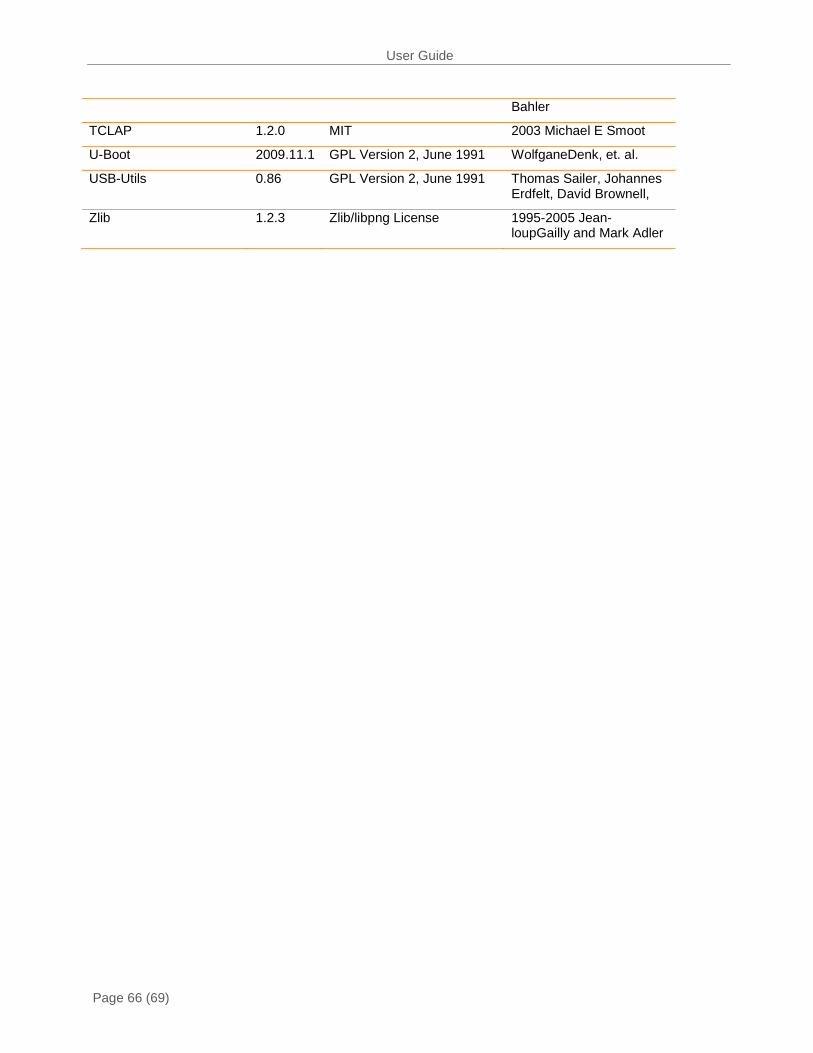
User Guide
Page 66 (69)
Bahler
TCLAP 1.2.0 MIT 2003 Michael E Smoot
U-Boot 2009.11.1 GPL Version 2, June 1991 WolfganeDenk, et. al.
USB-Utils 0.86 GPL Version 2, June 1991 Thomas Sailer, Johannes Erdfelt, David Brownell,
Zlib 1.2.3 Zlib/libpng License 1995-2005 Jean-loupGailly and Mark Adler
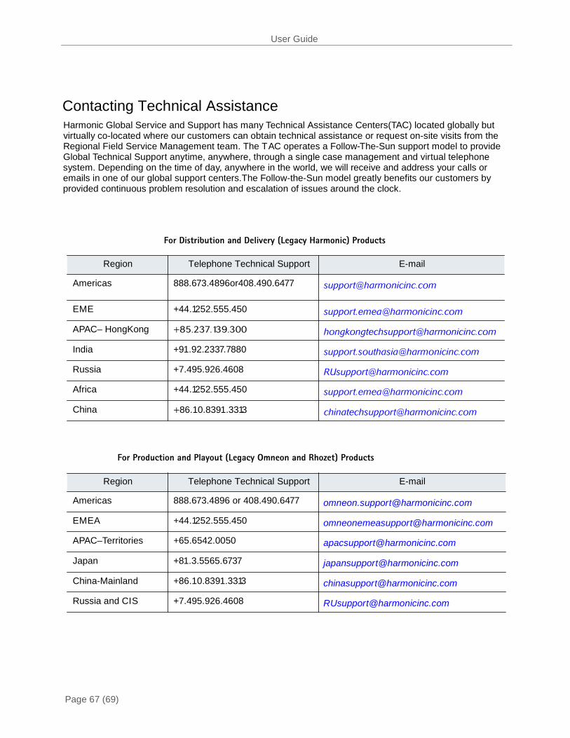
User Guide
Page 67 (69)
For Distribution and Delivery (Legacy Harmonic) Products
For Production and Playout (Legacy Omneon and Rhozet) Products
Region Telephone Technical Support E-mail
Americas 888.673.4896 or 408.490.6477
EMEA +44.1252.555.450
APAC–Territories +65.6542.0050
Japan +81.3.5565.6737
China-Mainland +86.10.8391.3313
Russia and CIS +7.495.926.4608
Region Telephone Technical Support E-mail
Americas
888.673.4896or408.490.6477
EME +44.1252.555.450
APAC– HongKong +85.237.139.300
India +91.92.2337.7880
Russia +7.495.926.4608
Africa +44.1252.555.450
China +86.10.8391.3313
Contacting Technical Assistance Harmonic Global Service and Support has many Technical Assistance Centers(TAC) located globally but virtually co-located where our customers can obtain technical assistance or request on-site visits from the Regional Field Service Management team. The T AC operates a Follow-The-Sun support model to provide Global Technical Support anytime, anywhere, through a single case management and virtual telephone system. Depending on the time of day, anywhere in the world, we will receive and address your calls or emails in one of our global support centers.The Follow-the-Sun model greatly benefits our customers by provided continuous problem resolution and escalation of issues around the clock.

User Guide
Page 68 (69)
The Harmonic Inc. Support website is: http://www.harmonicinc.com/services-support The Harmonic Inc. Distribution and Delivery product software downloads site is: ftp://ftp.harmonicinc.com The Harmonic Inc. Playout and Production software downloads site is: ftp://ftp.Omneon.com//Updates/Omneon/Current/ The Harmonic Inc. corporate address is: Harmonic Inc. 4300 North First St. San Jose, CA 95134, U.S.A. Attn: Customer Support
The corporate telephone numbers for Harmonic Inc. are:
Tel.1.800.788.1330 (from the U.S. and Canada) Tel. +1.408.542.2500 (outside the U.S. and Canada) Fax. +1.408.542.2511

Harmonic Inc. 4300 North First St.
San Jose, CA95134 USA www.harmonicinc.com
Copyright © 2012Harmonic Inc. 1.800.788.1330