Embed Size (px)
Citation preview

8/13/2019 Smiths Fluid Warmer - General Technical Manual
http://slidepdf.com/reader/full/smiths-fluid-warmer-general-technical-manual 1/131
Intentionally Blank
8/13/2019 Smiths Fluid Warmer - General Technical Manual
http://slidepdf.com/reader/full/smiths-fluid-warmer-general-technical-manual 2/131
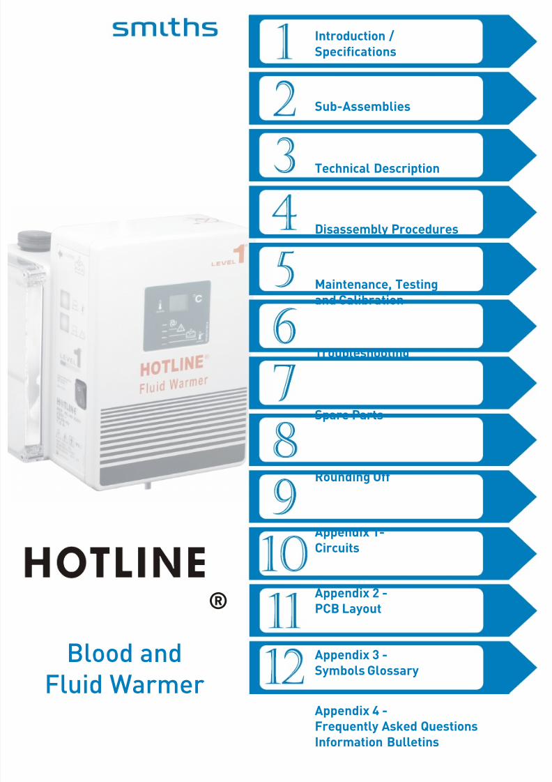
Introduction /Specifications
Technical Description
Sub-Assemblies
Disassembly Procedures
Spare Parts
Troubleshooting
Rounding Off
Appendix 1-Circuits
Appendix 2 -PCB Layout
Appendix 3 -Symbols Glossary
Appendix 4 -Frequently Asked QuestionsInformation Bulletins
Blood andFluid Warmer
®
Maintenance, Testingand Calibration
8/13/2019 Smiths Fluid Warmer - General Technical Manual
http://slidepdf.com/reader/full/smiths-fluid-warmer-general-technical-manual 3/131
HOTLINE ® Blood and Fluid Warmer Technical Service Pack i
P R E F A C E W e l c o m e . . .
Welcome...... to one of
Smiths Medical’sTechnical Service Packs
Who are we?
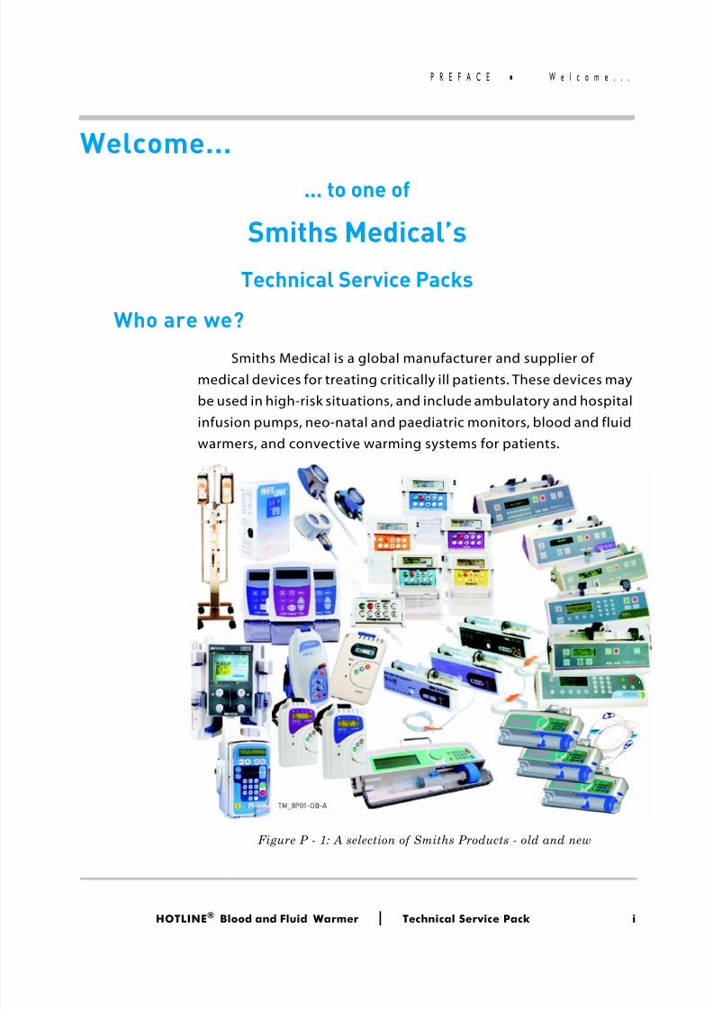
Smiths Medical is a global manufacturer and supplier ofmedical devices for treating critically ill patients. These devices maybe used in high-risk situations, and include ambulatory and hospitalinfusion pumps, neo-natal and paediatric monitors, blood and fluidwarmers, and convective warming systems for patients.
Figure P - 1: A selection of Smiths Products - old and new

8/13/2019 Smiths Fluid Warmer - General Technical Manual
http://slidepdf.com/reader/full/smiths-fluid-warmer-general-technical-manual 4/131
HOTLINE ® Blood and Fluid Warmer Technical Service Pack ii
P R E F A C E W e l c o m e . . .
Smiths Medical has a long history, bringing many well knownbrands to the market, such as Portex ®, Level 1 ®, BCI®, Graseby ®,Wallace ®, Bivona ®, Pneupac ®, Deltec ®, DHD® and Medex ® . It is partof the Smiths Group, a British engineering consortium founded in1851.
Now all of these formerly independent business units havebeen merged into one Global company — Smiths Medical. SmithsMedical is a world leader in the design, manufacture anddistribution of medical devices.
What about Level 1 ® ?
The Level 1 ® range of products is synonymous with a highquality, cost effective range of temperature management products. The range includes blood and fluid warming products for bothgravity flow and fast flow intravenous or irrigation applications, andconvective (hot air) warming systems. These products help to
prevent hypothermia and maintain normothermia in patientsundergoing surgery in the operating theatre, recovery ward and inthe casualty departments in emergency situations.
Why is Temperature Management important?
Patients undergoing surgical procedures are exposed to avariety of influences that have a effect on their ability to maintaintheir normal body temperature (Normothermia). If these factorspersist for a prolonged period of time, the patient will becomehypothermic, i.e., their body temperature drops below 36°C. Evenmild hypothermia (34°-36°C) puts patients at risk. Trauma cases andextensive procedures present well-known temperaturemanagement challenges. But so can routine operations. Clinicalevidence shows that warming is important in any case lasting morethan an hour and/or using more than one litre of fluid.
8/13/2019 Smiths Fluid Warmer - General Technical Manual
http://slidepdf.com/reader/full/smiths-fluid-warmer-general-technical-manual 5/131
HOTLINE ® Blood and Fluid Warmer Technical Service Pack iii
P R E F A C E W e l c o m e . . .
What hypothermia does to the patient
■ Cardiovascular instability
■ Vasoconstriction, decreased cardiac output, and changes inelectrical conduction can contribute to an increased incidence ofcardiac ischemia, arrhythmias, and arrest.
■ Increased coagulopathy
■ Coagulopathy may result in increased bleeding, possiblynecessitating blood transfusions.
■ Altered action and reduced clearance of anesthetics■ Hypothermia decreases a patient’s metabolism, resulting in a
need for higher amounts of anesthetics. It also contributes todelayed emergence from anesthesia and longer recovery roomstays.
■ Increased risk of wound infection
■ Wound infection and delayed wound healing result in longerhospital stays. Wound infection can prolong hospitalization.
■ Postoperative discomfort
■ Thermal discomfort, shivering, and fatigue can occur when coretemperature decreases by 1°C .
The HOTLINE® Blood and Fluid Warmer
The HOTLINE® Blood and Fluid Warmer uses a specialdisposable that totally encloses the patient’s end of the IVadministration set in a bath of warmed recirculating fluid. Thismeans that the IV fluid is introduced at or above core bodytemperature, rather than in the chilled state that it may have beenstored at.
This simple solution eliminates the chill being passed to thepatient, and assists the patient’s own efforts at maintainingnormothermia.
8/13/2019 Smiths Fluid Warmer - General Technical Manual
http://slidepdf.com/reader/full/smiths-fluid-warmer-general-technical-manual 6/131
HOTLINE ® Blood and Fluid Warmer Technical Service Pack iv
P R E F A C E W e l c o m e . . .
Published by:
Smiths Medical ASD, Inc.160 Weymouth St, Rockland, MA 02370, USA
■ For assistance or further information, contact Smiths Medical ASD, Inc. , Technical Service Department or your Smiths Medical ASD, Inc., d istributor at:
USA/ Canada
■ Smiths Medical ASD, Inc.160 Weymouth Street, Rockland, MA 02370 USA
■ USA/Canada 1-800-258-5361International +1-781-878-8011
European Representative
■ Smiths Medical International Ltd Colonial Way, Watford, Herts, WD24 4LG, UK Registered in England Number: 362847
■ Tel +44 (0) 1923 246434Fax +44 (0) 1923 231595
Australian Representative
■ Smiths Medical Australasia Pty. Ltd.61 Brandl Street, Brisbane Technology Park Eight Mile Plains, QLD 4113, Australia
■ Tel +61 (0) 7 3340 1300
Fax +61 (0) 7 3340 1399
World WideWeb:
■ www.smiths-medical.com
8/13/2019 Smiths Fluid Warmer - General Technical Manual
http://slidepdf.com/reader/full/smiths-fluid-warmer-general-technical-manual 7/131
HOTLINE ® Blood and Fluid Warmer Technical Service Pack v
P R E F A C E W e l c o m e . . .
■ All possible care has been taken in the preparation and production of this publication, but Smiths Medical accepts no
liability for any inaccuracies that may be found.■ This publication may be subject to revision and it is the user’s
responsibility to ensure that the correct version is usedappropriate to the intended use.
■ Users of the equipment must ensure that they have read andunderstood the contents of the complete manual including thewarnings and cautions and have been trained in the correct useof the product.
■ This publication has been compiled and approved by SmithsMedical for use with their respective products.
■ It may be supplied in a format that permits users to access thetext and illustrations for their own use (e.g., training andeducational purposes). Smiths Medical cannot be heldresponsible for the accuracy of, nor any resulting incident arisingfrom, information that has been extracted from this publicationand compiled into the user’s documentation.
■ Other than as herein noted, no part of this publication may be
reproduced, transmitted, transcribed, or stored in a retrievalsystem or translated into any human or computer language inany form or by any means without the prior permission of SmithsMedical.
■ “Graseby ®” “Smiths” “HOTLINE ®” and “LEVEL 1®” are alltrademarks of the Smiths Medical family of companies. All othertrademarks are acknowledged as the property of their respectiveowners.
■ The symbol ® indicates it is registered in the U.S. Patents andTrademarks Office and in certain other countries.
© 2006 Smiths Medical family of companies.All rights reserved.
8/13/2019 Smiths Fluid Warmer - General Technical Manual
http://slidepdf.com/reader/full/smiths-fluid-warmer-general-technical-manual 8/131
HOTLINE ® Blood and Fluid Warmer Technical Service Pack vi
P R E F A C E R e v i s i o n H i s t o r y
Revision History
IssueNo:
Reason for Change PagesAffected
Date
000 New Revision - First Release All July 2006
8/13/2019 Smiths Fluid Warmer - General Technical Manual
http://slidepdf.com/reader/full/smiths-fluid-warmer-general-technical-manual 9/131
HOTLINE ® Blood and Fluid Warmer Technical Service Pack vii
P R E F A C E A i m s
Aims To provide technical engineering support staff with the
practical and theoretical knowledge necessary to ...
■ ... diagnose,
■ maintain,
■ repair,
■ and update ...
... Smiths Medical products as appropriate to meet the needsof your healthcare establishment’s equipment managementprotocols.
8/13/2019 Smiths Fluid Warmer - General Technical Manual
http://slidepdf.com/reader/full/smiths-fluid-warmer-general-technical-manual 10/131
HOTLINE ® Blood and Fluid Warmer Technical Service Pack viii
P R E F A C E O b j e c t i v e s
Objectives This manual will give you the necessary information to enable
a qualified Biomedical Engineer or Technician with appropriateexperience to successfully tackle any repair or componentreplacement required, and recalibrate the unit either routinely orpost-repair work.
The materia l covered by this manual is also offered as part of atraining course that can be held either at Smiths Medical’s premises,or at your own establishment if that would be more convenient.Successful training course attendees may be certified bySmiths Medical, an option not open to non-attendees. Pleasecontact your local Smiths Medical distributor for more details. Westrongly recommend course attendance wherever possible, toensure the highest standards of maintenance for your HOTLINE®units.
On completion of the program, delegates will have knowledgeof the following:
■ General functionality and device application.
■ Principles of operation of electronic and mechanical systems.
■ Access to, and use of, the menu systems as appropriate.
■ Appropriate methods of testing and the equipment required.
■ Essential safety features and verification of performance.
■ Routine maintenance requirements.
■ Analysis of faults, fault codes and download software asappropriate.
8/13/2019 Smiths Fluid Warmer - General Technical Manual
http://slidepdf.com/reader/full/smiths-fluid-warmer-general-technical-manual 11/131
HOTLINE ® Blood and Fluid Warmer Technical Service Pack ix
C O N T E N T S
Contents
Section 1 - Introduction and Specifications
Superior Performance - - - - - - - - - - - - - - - - - 2Ease of Use - - - - - - - - - - - - - - - - - - - - - - 2Features - - - - - - - - - - - - - - - - - - - - - - - 3Specifications - - - - - - - - - - - - - - - - - - - - - 4
Environmental - - - - - - - - - - - - - - - - - - - 5Miscellaneous - - - - - - - - - - - - - - - - - - - 5
Contra-Indications - - - - - - - - - - - - - - - - - - - 6
Section 2 - Sub-assemblies
Enclosure - - - - - - - - - - - - - - - - - - - - - - 9-11Recirculating Solution Path - - - - - - - - - - - - - - - 12Interlock Block - - - - - - - - - - - - - - - - - - - - 13PCB Mounting - - - - - - - - - - - - - - - - - - - - 14
Section 3 - Technical DescriptionGeneral - - - - - - - - - - - - - - - - - - - - - - - - 16Mechanical - - - - - - - - - - - - - - - - - - - - - - 16Controls and Indicators - - - - - - - - - - - - - - - - 17
Side Panel - - - - - - - - - - - - - - - - - - - - - 17Electrical - - - - - - - - - - - - - - - - - - - - - - - 19
Power Circuits - - - - - - - - - - - - - - - - - - 19Control Circuit - - - - - - - - - - - - - - - - - - 20Digital Display - - - - - - - - - - - - - - - - - - - 22Thermistor Loss - - - - - - - - - - - - - - - - - 23Over Temperature Alarm - - - - - - - - - - - - - - 25Flasher - - - - - - - - - - - - - - - - - - - - - 27Interlock Alarm - - - - - - - - - - - - - - - - - - 29Recirculating Solution Level Alarm - - - - - - - - - 30
8/13/2019 Smiths Fluid Warmer - General Technical Manual
http://slidepdf.com/reader/full/smiths-fluid-warmer-general-technical-manual 12/131
HOTLINE ® Blood and Fluid Warmer Technical Service Pack x
C O N T E N T S
Section 4 - Disassembly Procedure
Tools you will need - - - - - - - - - - - - - - - - - - - 33 Disassembly - - - - - - - - - - - - - - - - - - - - - 34Step 1: Open the case - - - - - - - - - - - - - - - - 34Step 2: Remove the PCB - - - - - - - - - - - - - - 36Step 3: Release the Earth Stud - - - - - - - - - - - 40Step 4: The Recirculating Solution Return Pipe - - - - 41Step 5: Removing the Chassis - - - - - - - - - - - - 42
Reassembly - - - - - - - - - - - - - - - - - - - - - - 44
Section 5 - Maintenance, Testing and CalibrationBefore each use - - - - - - - - - - - - - - - - - - - - 46
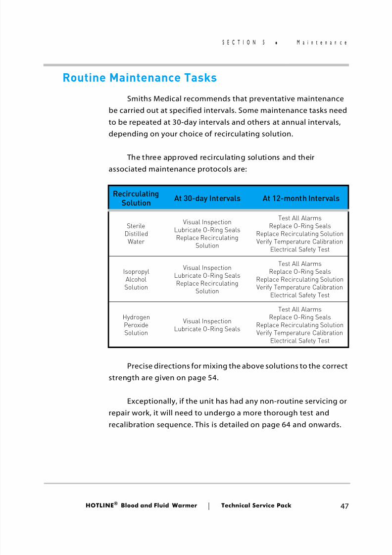
Lubrication of O-Ring Seals - - - - - - - - - - - - - 46After each use - - - - - - - - - - - - - - - - - - - - - 46Routine Maintenance Tasks - - - - - - - - - - - - - - - 47Every 30 days - - - - - - - - - - - - - - - - - - - - - 48Every 12 months - - - - - - - - - - - - - - - - - - - - 49Maintenance Solutions - - - - - - - - - - - - - - - - - 54Changing the Recirculating Solution - - - - - - - - - - - 54
Sterile Distilled Water - - - - - - - - - - - - - - - 54Isopropyl Alcohol Solution - - - - - - - - - - - - - - 56Hydrogen Peroxide Solution - - - - - - - - - - - - - 57
Routine Maintenance Checklists - - - - - - - - - - - - - 60Full Service Test Procedure - - - - - - - - - - - - - - - 64
Things you will need - - - - - - - - - - - - - - - - 64HL-90 Service Test Specification - - - - - - - - - - - 65
Section 6 - Troubleshooting
Troubleshooting Hints - - - - - - - - - - - - - - - - - 71Over Temperature Alarm always ON - - - - - - - - 71Over Temperature Alarm not working - - - - - - - - 72Fluid Warming Set Interlock Alarm always ON - - - - 72Fluid Warming Set Interlock Alarm not working - - - 72Low Recirculating Solution Level Alarm always ON - - 73Low Recirculating Solution Level Alarm not working - 73Non-Alarm related Faults - - - - - - - - - - - - - 74
8/13/2019 Smiths Fluid Warmer - General Technical Manual
http://slidepdf.com/reader/full/smiths-fluid-warmer-general-technical-manual 13/131
HOTLINE ® Blood and Fluid Warmer Technical Service Pack xi
C O N T E N T S
Section 7 - Spare Parts
Enclosure Parts for two-part case - - - - - - - - - - - 76Enclosure Parts for single-part case - - - - - - - - - - 77Float Switch and related parts - - - - - - - - - - - - - - 77Parts in the Recirculating Solution Path - - - - - - - - - 78P.C.B and mounting accessories - - - - - - - - - - - - - 79Water pump and related parts - - - - - - - - - - - - - - 79Interlock Block and related parts - - - - - - - - - - - - 80External Parts, Rear of case - - - - - - - - - - - - - - - 81Poleclamp parts - - - - - - - - - - - - - - - - - - - - 82
Section 8 - Rounding Off
Updates - - - - - - - - - - - - - - - - - - - - - - - - 84Modifications - - - - - - - - - - - - - - - - - - - - - 84GRI Pump - - - - - - - - - - - - - - - - - - - - - - - 86Float Switch Sealing Washer- - - - - - - - - - - - - - - 87
Appendix 1- Circuits
Appendix 2 - PCB Layout
PCB layout - - - - - - - - - - - - - - - - - - - - A2 - 2Component Listing - - - - - - - - - - - - - - - - - A2 - 3
Appendix 3 - Symbols Glossary
Appendix 4 - Customer Information Bulletins
HOTLINE®
Frequently Asked Questions - - - - - - - A4 - 2General Advisement - - - - - - - - - - - - - - - - A4 - 6HOTLINE® - Specific Announcements - - - - - - - - A4 - 7
8/13/2019 Smiths Fluid Warmer - General Technical Manual
http://slidepdf.com/reader/full/smiths-fluid-warmer-general-technical-manual 14/131
Introduction /Specifications
Blood andFluid Warmer
®
8/13/2019 Smiths Fluid Warmer - General Technical Manual
http://slidepdf.com/reader/full/smiths-fluid-warmer-general-technical-manual 15/131
HOTLINE ® Blood and Fluid Warmer Technical Service Pack 2
S E C T I O N 1 H O T L I N E ® H L - 9 0
HOTLINE® HL-90Blood and Fluid Warmer
The HOTLINE® HL-90 Blood and Fluid Warmer is designed foruse with the HOTLINE ® Warming Set to warm blood and IV fluids,and deliver them to the patient’s intravenous access site at normo-thermic temperatures under gravity flow conditions.
By jacketing the sterile patient IV line with a layer of precisely
controlled warmed recirculating solution, HOTLINE ® provides activewarming of the patient line all the way down to the patient connec-tion, thus eliminating “patient line cool-down.”
Superior Performance■ The HOTLINE® innovative tubing design eliminates “patient
line cool-down,” and delivers warm intravenous fluids to pa-
tients
Ease of Use■ Simple, 1-step plug-in disposable for fast setup and start
■ A 2.4 m (8 foot) patient line allows convenient positioning ofunit
■ Requires 60 - 70% less priming volume (20 ml)
■ Compatible with standard IV sets, infusion pumps and in-linehand pumps
8/13/2019 Smiths Fluid Warmer - General Technical Manual
http://slidepdf.com/reader/full/smiths-fluid-warmer-general-technical-manual 16/131
HOTLINE ® Blood and Fluid Warmer Technical Service Pack 3
S E C T I O N 1 H O T L I N E ® H L - 9 0
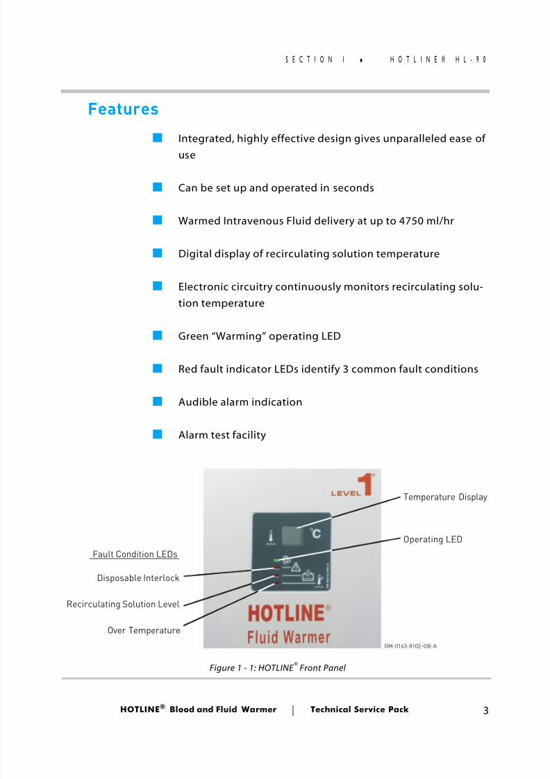
Features
■ Integrated, highly effective design gives unparalleled ease ofuse
■ Can be set up and operated in seconds
■ Warmed Intravenous Fluid delivery at up to 4750 ml/hr
■ Digital display of recirculating solution temperature
■ Electronic circuitry continuously monitors recirculating solu-tion temperature
■ Green “Warming” operating LED
■ Red fault indicator LEDs identify 3 common fault conditions
■Audible alarm indication
■ Alarm test facility
Temperature Display
Operating LED
Disposable Interlock
Recirculating Solution Level
Over Temperature
GM-0163-8102-GB-A
Fault Condition LEDs
Figure 1 - 1: HOTLINE ® Front Panel
8/13/2019 Smiths Fluid Warmer - General Technical Manual
http://slidepdf.com/reader/full/smiths-fluid-warmer-general-technical-manual 17/131
HOTLINE ® Blood and Fluid Warmer Technical Service Pack 4
S E C T I O N 1 S p e c i f i c a t i o n s
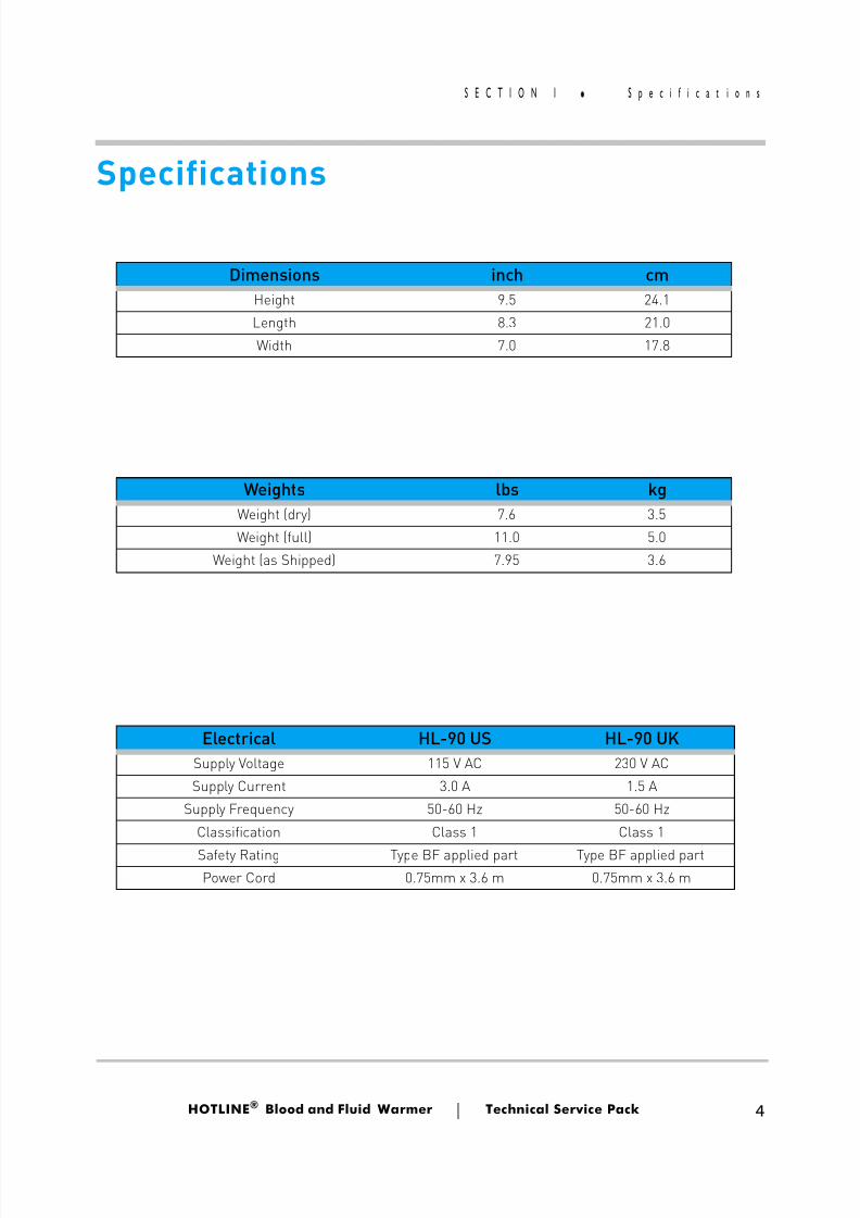
Specifications
Dimensions inch cmHeight 9.5 24.1Length 8.3 21.0Width 7.0 17.8
Weights lbs kgWeight (dry) 7.6 3.5Weight (full) 11.0 5.0
Weight (as Shipped) 7.95 3.6
Electrical HL-90 US HL-90 UKSupply Voltage 115 V AC 230 V ACSupply Current 3.0 A 1.5 A
Supply Frequency 50-60 Hz 50-60 HzClassification Class 1 Class 1
Safety Rating Type BF applied part Type BF applied partPower Cord 0.75mm x 3.6 m 0.75mm x 3.6 m
8/13/2019 Smiths Fluid Warmer - General Technical Manual
http://slidepdf.com/reader/full/smiths-fluid-warmer-general-technical-manual 18/131
HOTLINE ® Blood and Fluid Warmer Technical Service Pack 5
S E C T I O N 1 S p e c i f i c a t i o n s
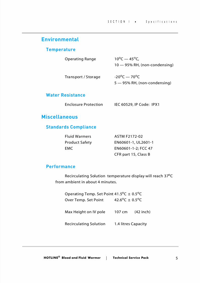
Environmental
TemperatureOperating Range 10 oC — 45 oC,
10 — 95% RH, (non-condensing)
Transport / Storage -20 oC — 70 oC5 — 95% RH, (non-condensing)
Water Resistance
Enclosure Protection IEC 60529, IP Code: IPX1
Miscellaneous
Standards Compliance
Fluid Warmers ASTM F2172-02Product Safety EN60601-1, UL2601-1
EMC EN60601-1-2; FCC 47CFR part 15, Class B
Performance
Recirculating Solution temperature display will reach 37 oCfrom ambient in about 4 minutes.
Operating Temp. Set Point 41.5 oC ± 0.5 oCOver Temp. Set Point 42.6 oC ± 0.5 oC
Max Height on IV pole 107 cm (42 inch)
Recirculating Solution 1.4 litres Capacity
8/13/2019 Smiths Fluid Warmer - General Technical Manual
http://slidepdf.com/reader/full/smiths-fluid-warmer-general-technical-manual 19/131
HOTLINE ® Blood and Fluid Warmer Technical Service Pack 6
S E C T I O N 1 C o n t r a - i n d i c a t i o n s
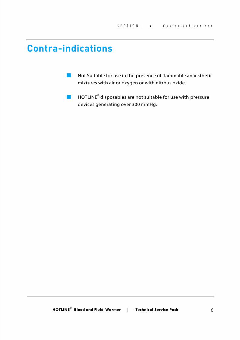
Contra-indications
■ Not Suitable for use in the presence of flammable anaestheticmixtures with air or oxygen or with nitrous oxide.
■ HOTLINE® disposables are not suitable for use with pressuredevices generating over 300 mmHg.
8/13/2019 Smiths Fluid Warmer - General Technical Manual
http://slidepdf.com/reader/full/smiths-fluid-warmer-general-technical-manual 20/131
Sub-Assemblies
Blood andFluid Warmer
®
8/13/2019 Smiths Fluid Warmer - General Technical Manual
http://slidepdf.com/reader/full/smiths-fluid-warmer-general-technical-manual 21/131
HOTLINE ® Blood and Fluid Warmer Technical Service Pack 8
S E C T I O N 2 S u b - a s s e m b l i e s
Sub-assemblies The principal sub-assemblies to be found in the HOTLINE ®
HL-90 are:
■ The enclosure and chassis parts
■ The recirculating solution path components
■ The PCB and i ts mountings
These are detailed on the following pages .
8/13/2019 Smiths Fluid Warmer - General Technical Manual
http://slidepdf.com/reader/full/smiths-fluid-warmer-general-technical-manual 22/131
HOTLINE ® Blood and Fluid Warmer Technical Service Pack 9
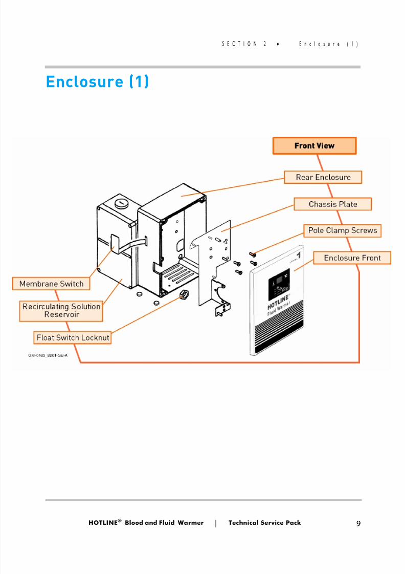
S E C T I O N 2 E n c l o s u r e ( 1 )
Enclosure (1)
8/13/2019 Smiths Fluid Warmer - General Technical Manual
http://slidepdf.com/reader/full/smiths-fluid-warmer-general-technical-manual 23/131
HOTLINE ® Blood and Fluid Warmer Technical Service Pack 10
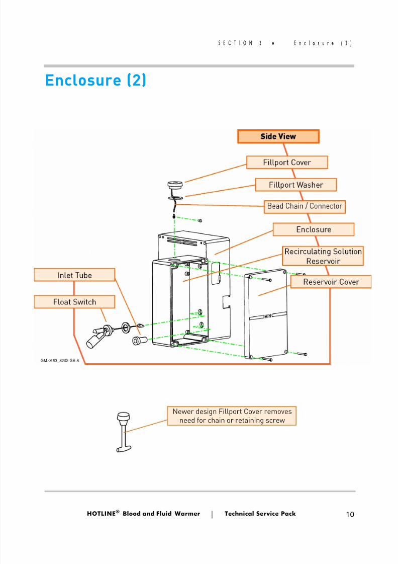
S E C T I O N 2 E n c l o s u r e ( 2 )
Enclosure (2)
Newer design Fillport Cover removesneed for chain or retaining screw
8/13/2019 Smiths Fluid Warmer - General Technical Manual
http://slidepdf.com/reader/full/smiths-fluid-warmer-general-technical-manual 24/131
HOTLINE ® Blood and Fluid Warmer Technical Service Pack 11
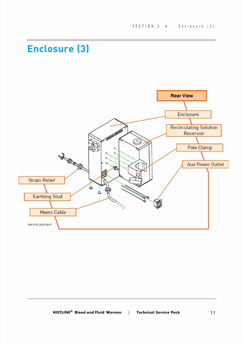
S E C T I O N 2 E n c l o s u r e ( 3 )
Enclosure (3)
8/13/2019 Smiths Fluid Warmer - General Technical Manual
http://slidepdf.com/reader/full/smiths-fluid-warmer-general-technical-manual 25/131
HOTLINE ® Blood and Fluid Warmer Technical Service Pack 12
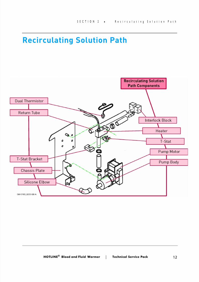
S E C T I O N 2 R e c i r c u l a t i n g S o l u t i o n P a t
Recirculating Solution Path
8/13/2019 Smiths Fluid Warmer - General Technical Manual
http://slidepdf.com/reader/full/smiths-fluid-warmer-general-technical-manual 26/131
HOTLINE ® Blood and Fluid Warmer Technical Service Pack 13
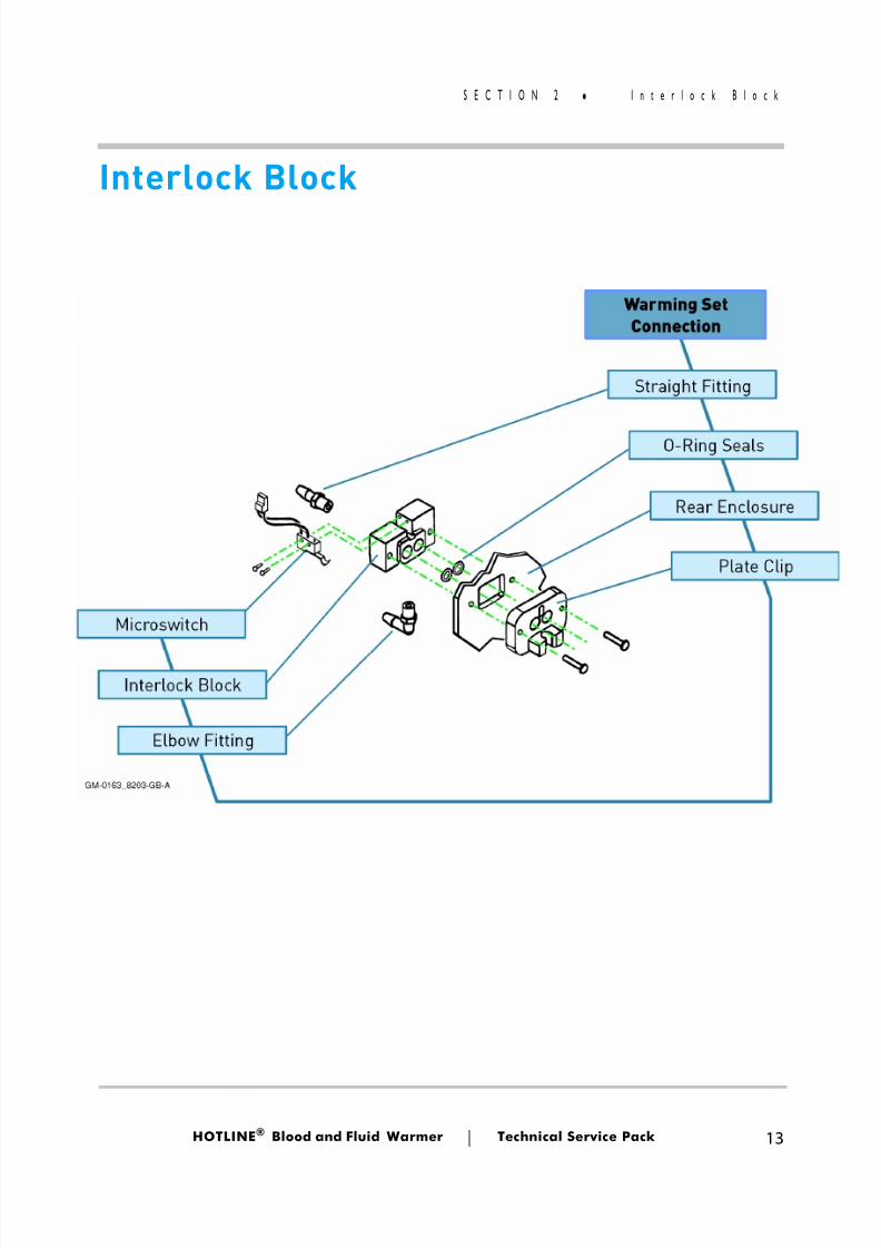
S E C T I O N 2 I n t e r l o c k B l o c k
Interlock Block
8/13/2019 Smiths Fluid Warmer - General Technical Manual
http://slidepdf.com/reader/full/smiths-fluid-warmer-general-technical-manual 27/131
HOTLINE ® Blood and Fluid Warmer Technical Service Pack 14
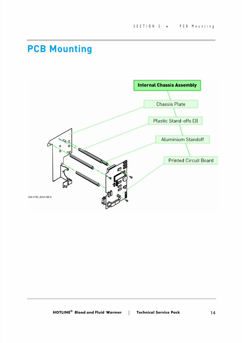
S E C T I O N 2 P C B M o u n t i n g
PCB Mounting
8/13/2019 Smiths Fluid Warmer - General Technical Manual
http://slidepdf.com/reader/full/smiths-fluid-warmer-general-technical-manual 28/131
Technical Description
Blood andFluid Warmer
®
8/13/2019 Smiths Fluid Warmer - General Technical Manual
http://slidepdf.com/reader/full/smiths-fluid-warmer-general-technical-manual 29/131
HOTLINE ® Blood and Fluid Warmer Technical Service Pack 16
S E C T I O N 3 T e c h n i c a l D e s c r i p t i o n
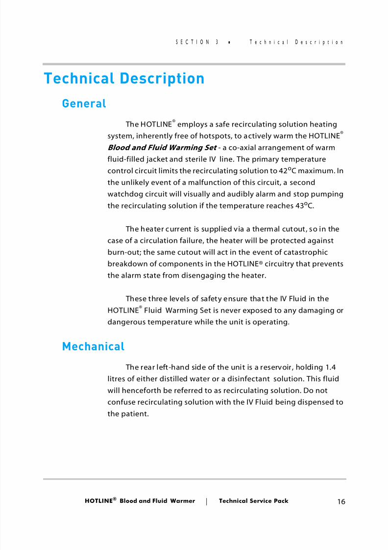
Technical DescriptionGeneral
The HOTLINE® employs a safe recirculating solution heatingsystem, inherently free of hotspots, to actively warm the HOTLINE ® Blood and Fluid Warming Set - a co-axial arrangement of warmfluid-filled jacket and sterile IV line. The primary temperaturecontrol circuit limits the recirculating solution to 42 oC maximum. Inthe unlikely event of a malfunction of this circuit, a second
watchdog circuit will visually and audibly alarm and stop pumpingthe recirculating solution if the temperature reaches 43 oC.
The heater current is supplied via a thermal cutout, so in thecase of a circulation failure, the heater will be protected againstburn-out; the same cutout will act in the event of catastrophicbreakdown of components in the HOTLINE® circuitry that preventsthe alarm state from disengaging the heater.
These three levels of safety ensure that the IV Fluid in theHOTLINE® Fluid Warming Set is never exposed to any damaging ordangerous temperature while the unit is operating.
Mechanical
The rear left-hand side of the unit is a reservoir, holding 1.4litres of either distilled water or a disinfectant solution. This fluidwill henceforth be referred to as recirculating solution. Do notconfuse recirculating solution with the IV Fluid being dispensed tothe patient.
8/13/2019 Smiths Fluid Warmer - General Technical Manual
http://slidepdf.com/reader/full/smiths-fluid-warmer-general-technical-manual 30/131
HOTLINE ® Blood and Fluid Warmer Technical Service Pack 17
S E C T I O N 3 T e c h n i c a l D e s c r i p t i o n
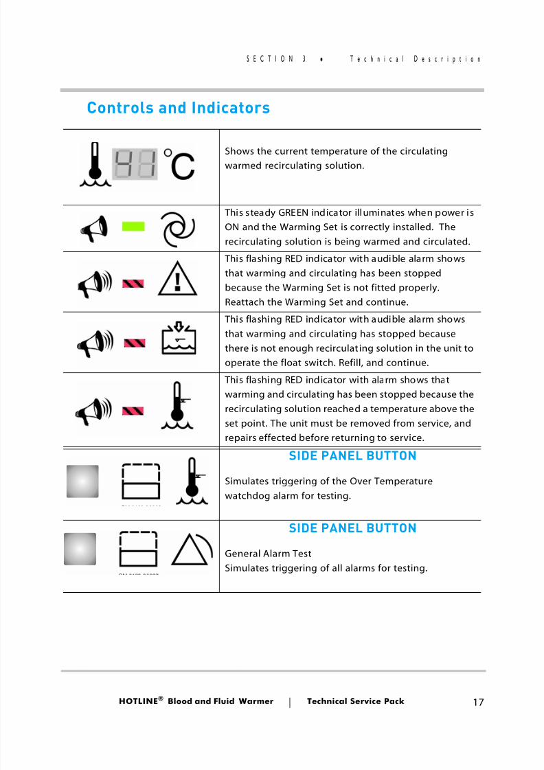
Controls and Indicators
Shows the current temperature of the circulatingwarmed recirculating solution.
This s teady GREEN indicator illuminates when power isON and the Warming Set is correctly installed. Therecirculating solution is being warmed and circulated.
This flashing RED indicator with audible alarm showsthat warming and circulating has been stoppedbecause the Warming Set is not fitted properly.Reattach the Warming Set and continue.
This flashing RED indicator with audible alarm showsthat warming and circulating has stopped becausethere is not enough recirculat ing solution in the unit tooperate the float switch. Refill, and continue.
This flashing RED indicator with alarm shows thatwarming and circulating has been stopped because therecirculating solution reached a temperature above theset point. The unit must be removed from service, andrepairs effected before returning to service.
SIDE PANEL BUTTON
Simulates triggering of the Over Temperaturewatchdog alarm for testing.
SIDE PANEL BUTTON
General Alarm TestSimulates triggering of all alarms for testing.
8/13/2019 Smiths Fluid Warmer - General Technical Manual
http://slidepdf.com/reader/full/smiths-fluid-warmer-general-technical-manual 31/131
HOTLINE ® Blood and Fluid Warmer Technical Service Pack 18
S E C T I O N 3 T e c h n i c a l D e s c r i p t i o n
Mechanical (contd)
The outer face of the reservoir is transparent so therecirculating solution level and flow can both be observed. A floatswitch is fitted in the tank, so that the unit cannot operate if there isinsufficient recirculating solution to properly circulate.Recirculating solution is drawn from the bottom of the reservoir, viaa silicone rubber elbow into a centrifugal pump driven by a 60VAsynchronous electric motor in the main enclosure.
The pump outlet is vertically upwards, and feeds into theheater assembly via another short length of silicone rubber piping. The heater asembly is a solid cast L-shaped unit that, in the verticalleg, incorporates a 300 watt heater element, able to warm therecirculating solution from room temperature to 37 oC in 4 minutes.In the horizontal leg of the heater assembly, a special dualthermistor unit is submerged in the flow, to monitor and control thewarmed recirculating solution temperature.
Clamped to the external surface of the heater assembly is the T - Stat, a thermally-operated bi-metallic cutout that breaks thecircuit at temperatures above 50 oC. The cutout only self-resetswhen the temperature has dropped significantly (10 oC - 15oC)below its nominal operating temperature.
The warmed recirculating solution leaving the heaterassembly now enters the interlock block, at the top right-hand sideof the HOTLINE ®. This interfaces to the Fluid Warming Set thatcontains the sterile line for the patient’s IV fluid. The Fluid WarmingSet needs to be in place so as to operate a microswitch that wouldotherwise raise an alarm and cut off the pump. Running back fromthe interlock block is the recirculating solution return line, whichleads directly throught the rear of the main enclosure and into thetop of the reservoir.

8/13/2019 Smiths Fluid Warmer - General Technical Manual
http://slidepdf.com/reader/full/smiths-fluid-warmer-general-technical-manual 32/131
HOTLINE ® Blood and Fluid Warmer Technical Service Pack 19
S E C T I O N 3 T e c h n i c a l D e s c r i p t i o n
Electrical Power Circuits
Power circuitry is conventional, and is constructed on the PCB. There are three fuses, F1 and F2 (both 1.5A) for the Mains input, andF3 (375 mA) for the low voltage circuits. F3 is wire-ended device,soldered into place at the top edge of the PCB.
On the Mains side, the power normally passes through a linefilter to reduce susceptibility to interference (this filter is not alwaysrequired for domestic US units.) The pump motor is switched by a
PCB-mounted relay K1, and the heater element is controlled by atriac. The heater can only be energised when the pump is poweredon, since without recirculating solution flow, the heater elementwould quickly overheat.
The heater triac is triggered via an optical isolator, and all theMains voltage circuits are physically distanced from the low-voltagecircuits for safety reasons. The low-voltage control circuits are
13
U501
U1
+
CR1
F3 375mA
7
9
10
12
1
R5023.16k
C 2220Fµ
C50110Fµ
R501453R
T1
F1 1.5A
SW1
DPST
Thermofuse56 Co
F2 1.5A
R41k
J7
L
N
E
J6
U2TRIAC
R3270R
U3OPTO
K1Contacts
2
4
6
8
1
3
5
7
TB1
TB1
Earth Stud
WaterHeater
PumpMotor
AUXOutlet
TB1
TB1LineInput
J10
1
3
4
6MT2
6
4
Gate
1
2
MT1C
VU
10
38
30
22
26
LF1Filter
14
R5023.16k
C100100pF
GM-HL90_8A103
Figure 3 - 1: HOTLINE ® Power Circuits
8/13/2019 Smiths Fluid Warmer - General Technical Manual
http://slidepdf.com/reader/full/smiths-fluid-warmer-general-technical-manual 33/131
HOTLINE ® Blood and Fluid Warmer Technical Service Pack 20
S E C T I O N 3 T e c h n i c a l D e s c r i p t i o n
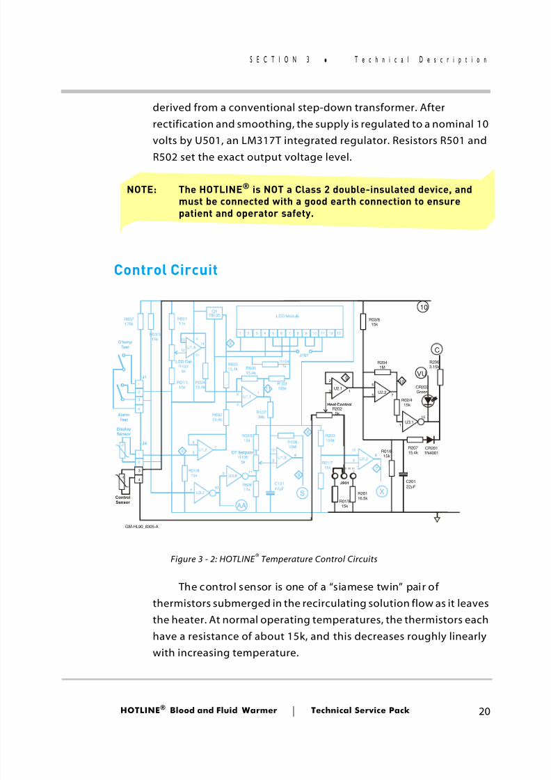
derived from a conventional step-down transformer. Afterrectification and smoothing, the supply is regulated to a nominal 10volts by U501, an LM317T integrated regulator. Resistors R501 andR502 set the exact output voltage level.
NOTE: The HOTLINE® is NOT a Class 2 double-insulated device, andmust be connected with a good earth connection to ensurepatient and operator safety.
Control Circuit
The control sensor is one of a “siamese twin” pair ofthermistors submerged in the recirculating solution flow as it leavesthe heater. At normal operating temperatures, the thermistors eachhave a resistance of about 15k, and this decreases roughly linearlywith increasing temperature.
Q178L05 LCD Module
AlarmTest
O'tempTest
ControlSensor
DisplaySensor
U1.4
U1.1
U1.2
J4
J1
U3.1
U2.2
U2.3
J201
U3.7
10
1 2 3 4 5 6 7 8 9 1 0 11 12 13
-t
-t
1
1
2
2
3
3
4
4
U3.6
VU
C
S
AA
X
5
8
4
11
9
6
10
7
R2025k
Heat Control
R203154kR108
10M
R03/515k
OT SetpointR106
5k
LCD CalR102
5k
R10734k
R50415.4k
R60315.4k
R607178k
R60111k
R03/315k
R01/115k
R60215.4k
R01/615k
R60515.4k
R103105k
R1041k
J101
R60611k
R01/715k
R2041M
R02/415k
R03/815k
R01/815k
R01/915k
R20116.5k
R2063.15k
R20715.4k
CR2011N4001
C20122 Fµ
C10147 Fµ
U1.3
1211
41314
5
9 9
35
1
6
11
10
10 10
26
7
5
7
8 8
17
15
2
3
1U2.1 CR202
Green
GM-HL90_8305-A
Figure 3 - 2: HOTLINE ® Temperature Control Circuits
8/13/2019 Smiths Fluid Warmer - General Technical Manual
http://slidepdf.com/reader/full/smiths-fluid-warmer-general-technical-manual 34/131
HOTLINE ® Blood and Fluid Warmer Technical Service Pack 21
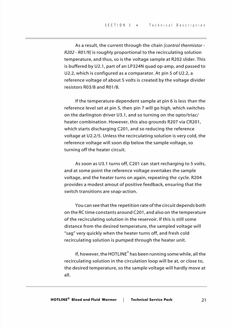
S E C T I O N 3 T e c h n i c a l D e s c r i p t i o n
As a result, the current through the chain [control thermistor -R202 - R01/9] is roughly proportional to the recirculating solutiontemperature, and thus, so is the voltage sample at R202 slider. Thisis buffered by U2.1, part of an LP324N quad op-amp, and passed toU2.2, which is configured as a comparator. At pin 5 of U2.2, areference voltage of about 5 volts is created by the voltage dividerresistors R03/8 and R01/8.
If the temperature-dependent sample at pin 6 is less than thereference level set at pin 5, then pin 7 will go high, which switches
on the darlington driver U3.1, and so turning on the opto/triac/heater combination. However, this also grounds R207 via CR201,which starts discharging C201, and so reducing the referencevoltage at U2.2/5. Unless the recirculating solution is very cold, thereference voltage will soon dip below the sample voltage, soturning off the heater circuit.
As soon as U3.1 turns off, C201 can start recharging to 5 volts,
and at some point the reference voltage overtakes the samplevoltage, and the heater turns on again, repeating the cycle. R204provides a modest amout of positive feedback, ensuring that theswitch transitions are snap-action.
You can see that the repetition rate of the circuit depends bothon the RC time constants around C201, and also on the temperatureof the recirculating solution in the reservoir. If this is still somedistance from the desired temperature, the sampled voltage will“sag” very quickly when the heater turns off, and fresh coldrecirculating solution is pumped through the heater unit.
If, however, the HOTLINE ® has been running some while, all therecirculating solution in the circulation loop will be at, or close to,the desired temperature, so the sample voltage will hardly move atall.
8/13/2019 Smiths Fluid Warmer - General Technical Manual
http://slidepdf.com/reader/full/smiths-fluid-warmer-general-technical-manual 35/131
HOTLINE ® Blood and Fluid Warmer Technical Service Pack 22
S E C T I O N 3 T e c h n i c a l D e s c r i p t i o n
Digital Display
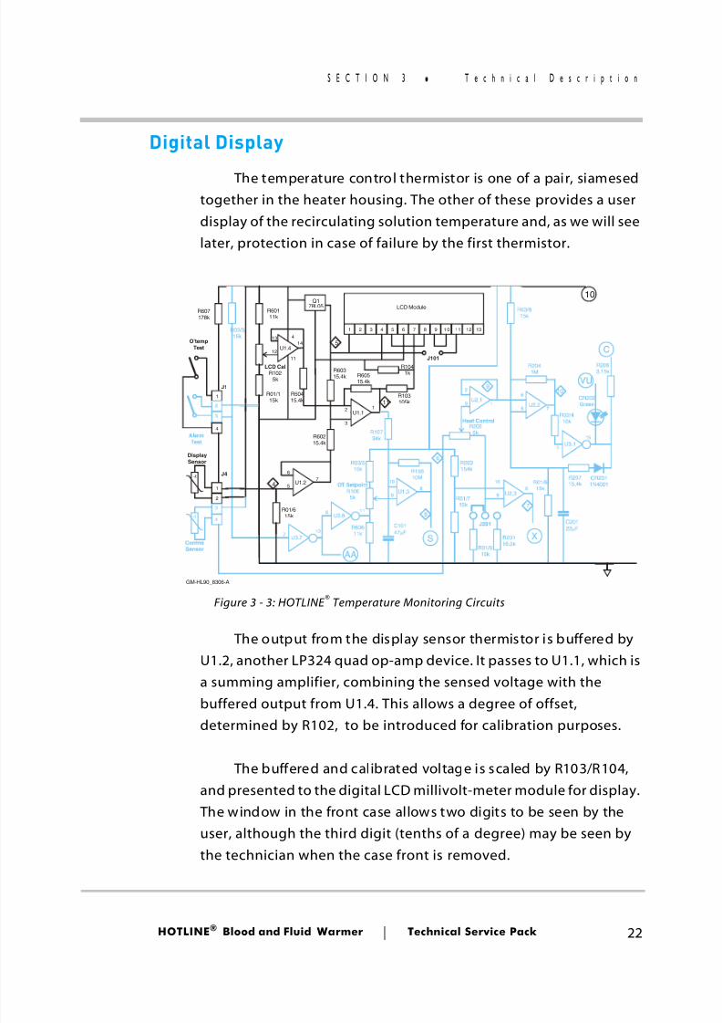
The temperature control thermistor is one of a pair, siamesedtogether in the heater housing. The other of these provides a userdisplay of the recirculating solution temperature and, as we will seelater, protection in case of failure by the first thermistor.
The output from the display sensor thermistor is buffered byU1.2, another LP324 quad op-amp device. It passes to U1.1, which isa summing amplifier, combining the sensed voltage with thebuffered output from U1.4. This allows a degree of offset,determined by R102, to be introduced for calibration purposes.
The buffered and calibrated voltage is scaled by R103/R104,and presented to the digital LCD millivolt-meter module for display. The window in the front case allows two digits to be seen by theuser, although the third digit (tenths of a degree) may be seen bythe technician when the case front is removed.
Q178L05 LCD Module
AlarmTest
O'tempTest
ControlSensor
DisplaySensor
U1.4
U1.1
U1.2
J4
J1
U3.1
U2.2
U2.3
J201
U3.7
10
1 2 3 4 5 6 7 8 9 1 0 11 12 13
-t
-t
1
1
2
2
3
3
4
4
U3.6
VU
C
S
AA
X
5
8
4
11
9
6
10
7
R2025k
Heat Control
R203154kR108
10M
R03/515k
OT SetpointR106
5k
LCD CalR102
5k
R10734k
R50415.4k
R60315.4k
R607178k
R60111k
R03/315k
R01/115k
R60215.4k
R01/615k
R60515.4k
R103105k
R1041k
J101
R606
11k
R01/715k
R2041M
R02/415k
R03/815k
R01/815k
R01/915k
R20116.5k
R2063.15k
R20715.4k
CR2011N4001
C20122 Fµ
C101
47 Fµ
U1.3
1211
41314
5
9 9
35
1
6
11
10
10 10
26
7
5
7
8 8
17
15
2
3
1U2.1 CR202
Green
GM-HL90_8306-A
Figure 3 - 3: HOTLINE ® Temperature Monitoring Circuits
8/13/2019 Smiths Fluid Warmer - General Technical Manual
http://slidepdf.com/reader/full/smiths-fluid-warmer-general-technical-manual 36/131
HOTLINE ® Blood and Fluid Warmer Technical Service Pack 23
S E C T I O N 3 T e c h n i c a l D e s c r i p t i o n
Thermistor Loss
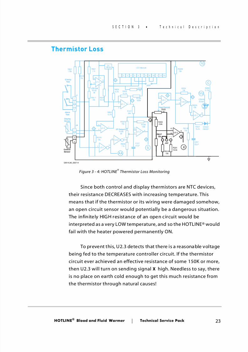
Since both control and display thermistors are NTC devices,their resistance DECREASES with increasing temperature. Thismeans that if the thermistor or its wiring were damaged somehow,an open circuit sensor would potentially be a dangerous situation. The infinitely HIGH resistance of an open circuit would beinterpreted as a very LOW temperature, and so the HOTLINE® wouldfail with the heater powered permanently ON.
To prevent this, U2.3 detects that there is a reasonable voltagebeing fed to the temperature controller circuit. If the thermistorcircuit ever achieved an effective resistance of some 150K or more,then U2.3 will turn on sending signal X high. Needless to say, thereis no place on earth cold enough to get this much resistance fromthe thermistor through natural causes!
Q178L05 LCD Module
AlarmTest
O'tempTest
ControlSensor
DisplaySensor
U1.4
U1.1
U1.2
J4
J1
U3.1
U2.2
U2.3
J201
U3.7
10
1 2 3 4 5 6 7 8 9 1 0 11 12 13
-t
-t
1
1
2
2
3
3
4
4
U3.6
VU
C
S
AA
X
5
8
4
11
9
6
10
7
R2025k
Heat Control
R203154kR10810M
R03/515k
OT SetpointR106
5k
LCD CalR102
5k
R10734k
R50415.4k
R60315.4k
R607178k
R60111k
R03/315k
R01/115k
R60215.4k
R01/615k
R60515.4k
R103105k
R1041k
J101
R60611k
R01/715k
R2041M
R02/415k
R03/815k
R01/815k
R01/915k
R20116.5k
R2063.15k
R20715.4k
CR2011N4001
C20122 Fµ
C10147 Fµ
U1.3
1211
41314
5
9 9
35
1
6
11
10
10 10
26
7
5
7
8 8
17
15
2
3
1U2.1 CR202
Green
R01/715k
GM-HL90_8307-A
Figure 3 - 4: HOTLINE ® Thermistor Loss Monitoring
8/13/2019 Smiths Fluid Warmer - General Technical Manual
http://slidepdf.com/reader/full/smiths-fluid-warmer-general-technical-manual 37/131
HOTLINE ® Blood and Fluid Warmer Technical Service Pack 24
S E C T I O N 3 T e c h n i c a l D e s c r i p t i o n
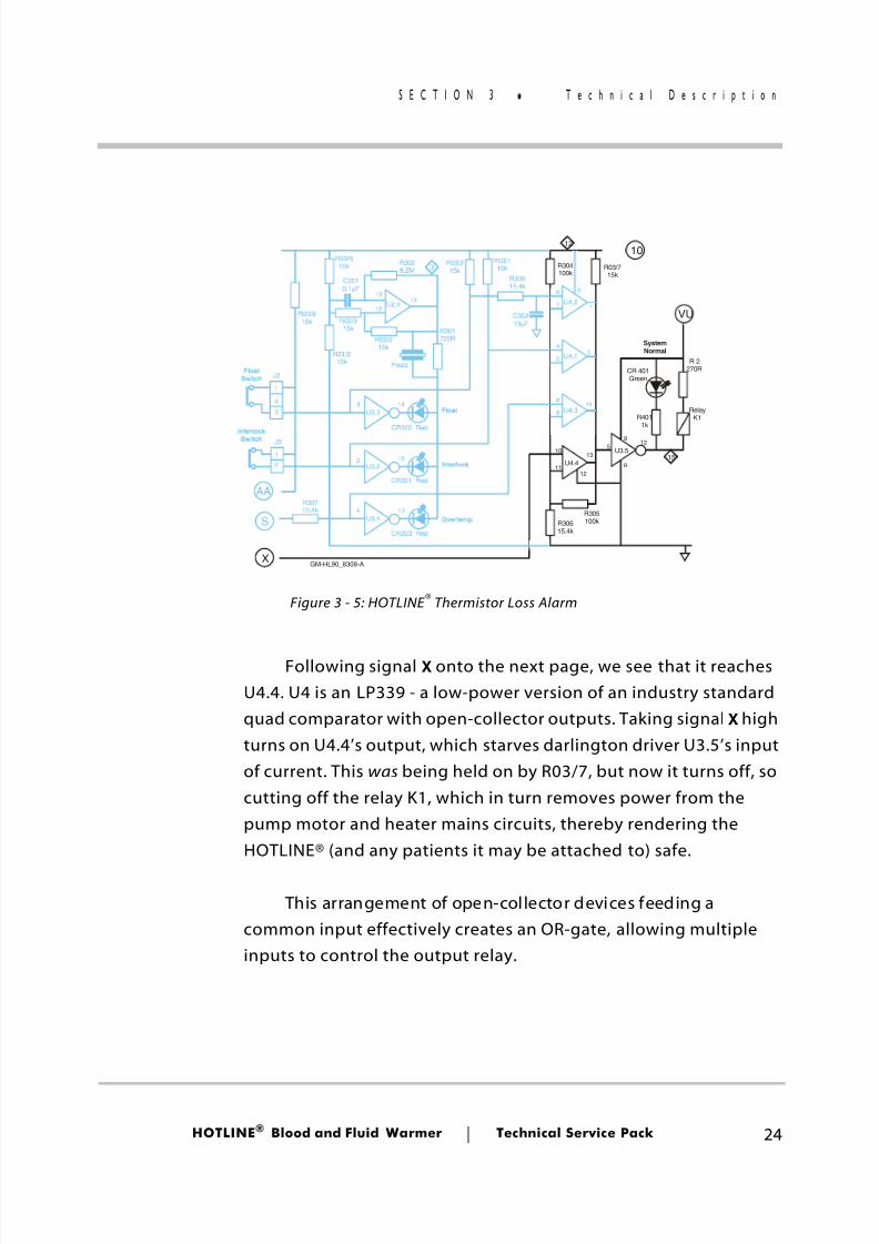
Following signal X onto the next page, we see that it reachesU4.4. U4 is an LP339 - a low-power version of an industry standardquad comparator with open-collector outputs. Taking signal X highturns on U4.4’s output, which starves darlington driver U3.5’s inputof current. This was being held on by R03/7, but now it turns off, socutting off the relay K1, which in turn removes power from thepump motor and heater mains circuits, thereby rendering theHOTLINE® (and any patients it may be attached to) safe.
This arrangement of open-collector devices feeding acommon input effectively creates an OR-gate, allowing multipleinputs to control the output relay.
FloatSwitch
Float
SystemNormal
Interlock Switch
Interlock
Overtemp
J3
J2
U4.2
U4.1
U4.3
U4.4
RelayK1
U3.3
Piezo
U3.2
U3.4
U3.5
U2.4
S
X
AA
10
VU
15
12
3
R305100k
R03/715k
R03/115k
R03/215k
R3028.2M
R30715.4k
R301722RR02/2
15k
R02/315k
R01/215k
R03/615k
R03/915k
R304100k
R30815.4k
R30615.4k
CR302 Red
CR301 Red
CR303 Red
R 2270RCR 401
Green
R4011k
C30210 Fµ
C3010.1 Fµ 3
2
14
4
13 6
5
12 7
10
1112
135
9
8
12
33
1
1
2
2 2
4
15
14
13
814
9
1
GM-HL90_8308-A
Figure 3 - 5: HOTLINE ® Thermistor Loss Alarm
8/13/2019 Smiths Fluid Warmer - General Technical Manual
http://slidepdf.com/reader/full/smiths-fluid-warmer-general-technical-manual 38/131
HOTLINE ® Blood and Fluid Warmer Technical Service Pack 25
S E C T I O N 3 T e c h n i c a l D e s c r i p t i o n
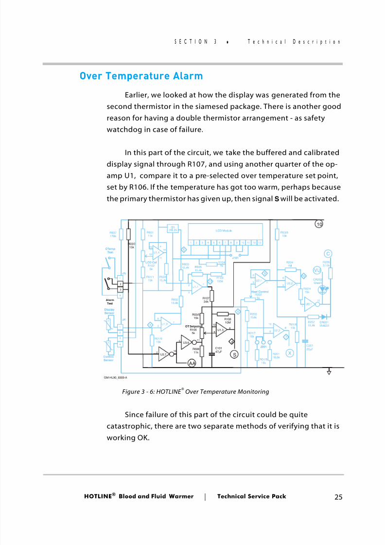
Over Temperature Alarm
Earlier, we looked at how the display was generated from thesecond thermistor in the siamesed package. There is another goodreason for having a double thermistor arrangement - as safetywatchdog in case of failure.
In this part of the circuit, we take the buffered and calibrateddisplay signal through R107, and using another quarter of the op-amp U1, compare it to a pre-selected over temperature set point,
set by R106. If the temperature has got too warm, perhaps becausethe primary thermistor has given up, then signal S will be activated.
Since failure of this part of the circuit could be quitecatastrophic, there are two separate methods of verifying that it isworking OK.
Q178L05 LCD Module
AlarmTest
O'tempTest
ControlSensor
DisplaySensor
U1.4
U1.1
U1.2
J4
J1
U3.1
U2.2
U2.3
J201
U3.7
10
1 2 3 4 5 6 7 8 9 1 0 11 12 13
-t
-t
1
1
2
2
3
3
4
4
U3.6
VU
C
S
AA
X
5
8
4
11
9
6
10
7
R2025k
Heat Control
R203154kR108
10M
R03/515k
OT SetpointR106
5k
LCD CalR102
5k
R10734k
R50415.4k
R60315.4k
R607178k
R60111k
R03/315k
R01/115k
R60215.4k
R01/615k
R60515.4k
R103105k
R1041k
J101
R60611k
R01/715k
R2041M
R02/415k
R03/815k
R01/815k
R01/915k
R20116.5k
R2063.15k
R20715.4k
CR2011N4001
C20122 Fµ
C10147 Fµ
U1.3
1211
41314
5
9 9
35
1
6
11
10
10 10
26
7
5
7
8 8
17
15
2
3
1
U2.1 CR202Green
GM-HL90_8309-A
Figure 3 - 6: HOTLINE ® Over Temperature Monitoring
8/13/2019 Smiths Fluid Warmer - General Technical Manual
http://slidepdf.com/reader/full/smiths-fluid-warmer-general-technical-manual 39/131
HOTLINE ® Blood and Fluid Warmer Technical Service Pack 26
S E C T I O N 3 T e c h n i c a l D e s c r i p t i o n
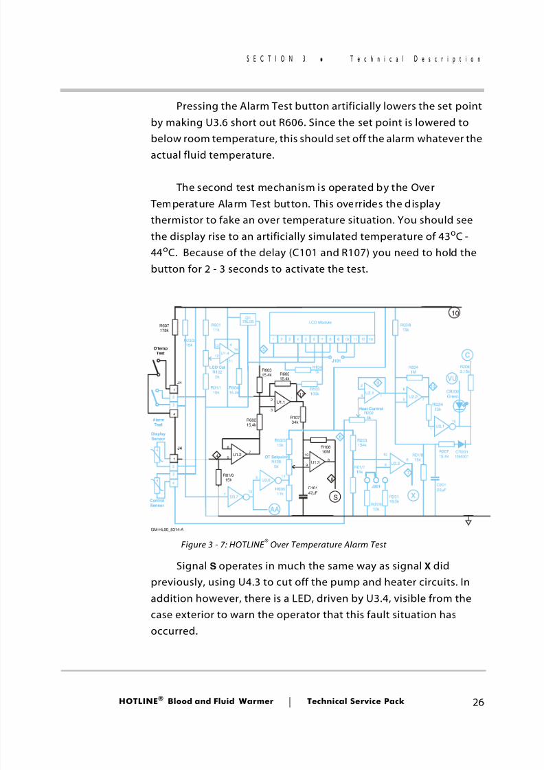
Pressing the Alarm Test button artificially lowers the set pointby making U3.6 short out R606. Since the set point is lowered tobelow room temperature, this should set off the alarm whatever theactual fluid temperature.
The second test mechanism is operated by the Over Temperature Alarm Test button. This overrides the displaythermistor to fake an over temperature situation. You should seethe display rise to an artificially simulated temperature of 43 oC -44 oC. Because of the delay (C101 and R107) you need to hold the
button for 2 - 3 seconds to activate the test.
Signal S operates in much the same way as signal X didpreviously, using U4.3 to cut off the pump and heater circuits. Inaddition however, there is a LED, driven by U3.4, visible from thecase exterior to warn the operator that this fault situation hasoccurred.
Q178L05 LCD Module
AlarmTest
O'tempTest
ControlSensor
DisplaySensor
U1.4
U1.1
U1.2
J4
J1
U3.1
U2.2
U2.3
J201
U3.7
10
1 2 3 4 5 6 7 8 9 1 0 11 12 13
-t
-t
1
1
2
2
3
3
4
4
U3.6
VU
C
S
AA
X
5
8
4
11
9
6
10
7
R2025k
Heat Control
R203154kR108
10M
R03/515k
OT SetpointR106
5k
LCD CalR102
5k
R10734k
R50415.4k
R60315.4k
R607178k
R60111k
R03/315k
R01/115k
R60215.4k
R01/615k
R60515.4k
R103105k
R1041k
J101
R60611k
R01/715k
R2041M
R02/415k
R03/815k
R01/815k
R01/915k
R20116.5k
R2063.15k
R20715.4k
CR2011N4001
C20122 Fµ
C10147 Fµ
U1.3
1211
41314
5
9 9
35
1
6
11
10
10 10
26
7
5
7
8 8
17
15
2
3
1U2.1 CR202
Green
GM-HL90_8314-A
Figure 3 - 7: HOTLINE ® Over Temperature Alarm Test
8/13/2019 Smiths Fluid Warmer - General Technical Manual
http://slidepdf.com/reader/full/smiths-fluid-warmer-general-technical-manual 40/131
8/13/2019 Smiths Fluid Warmer - General Technical Manual
http://slidepdf.com/reader/full/smiths-fluid-warmer-general-technical-manual 41/131
HOTLINE ® Blood and Fluid Warmer Technical Service Pack 28
S E C T I O N 3 T e c h n i c a l D e s c r i p t i o n
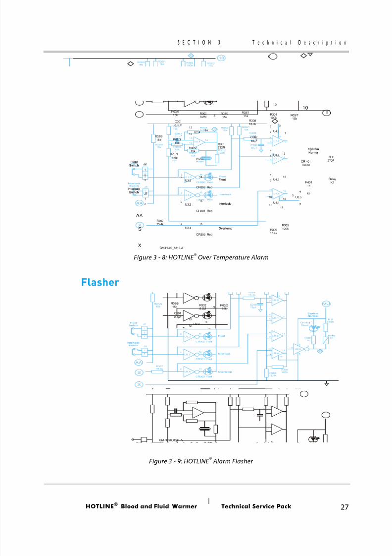
The alarm LED does not return directly to the positive rail, asyou might expect. Instead it gets its power from U2.4, which isconfigured as a low-frequency square-wave oscillator. This meansthat the LED can only light up when U2.4’s output is high - so itflashes on and off to attract attention.
Whenever the LED is ON the piezo-sounder is powered by thevolt-drop across the LED’s current-limiting resistor R301, so it beepsin synchronism with the flashing of the alarm LED.
Exercise: If more than one alarm happened at once, then two ormore LEDs would be flashed by this circuit. The extra current drainshould increase the volt-drop across R301, so you would expect thePiezo-sounder to increase in power and volume for every extra alarmcondition.
QUESTION...
Guess how much percentage increase in beep volume resultsfrom ALL alarms simultaneously, compared to a single alarm?
Now try to justify your answer!
8/13/2019 Smiths Fluid Warmer - General Technical Manual
http://slidepdf.com/reader/full/smiths-fluid-warmer-general-technical-manual 42/131
HOTLINE ® Blood and Fluid Warmer Technical Service Pack 29
S E C T I O N 3 T e c h n i c a l D e s c r i p t i o n
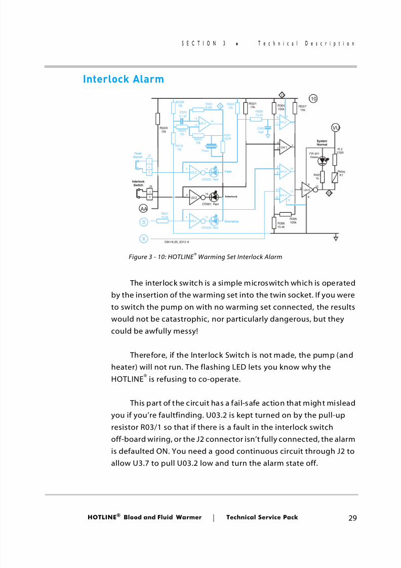
Interlock Alarm
The interlock switch is a simple microswitch which is operated
by the insertion of the warming set into the twin socket. If you wereto switch the pump on with no warming set connected, the resultswould not be catastrophic, nor particularly dangerous, but theycould be awfully messy!
Therefore, if the Interlock Switch is not made, the pump (andheater) will not run. The flashing LED lets you know why theHOTLINE® is refusing to co-operate.
This part of the circuit has a fail-safe action that might misleadyou if you’re faultfinding. U03.2 is kept turned on by the pull-upresistor R03/1 so that if there is a fault in the interlock switchoff-board wiring, or the J2 connector isn’t fully connected, the alarmis defaulted ON. You need a good continuous circuit through J2 toallow U3.7 to pull U03.2 low and turn the alarm state off.
FloatSwitch
Float
SystemNormal
Interlock Switch
Interlock
Overtemp
J3
J2
U4.2
U4.1
U4.3
U4.4
RelayK1
U3.3
Piezo
U3.2
U3.4
U3.5
U2.4
S
X
AA
10
VU
15
12
3
R305100k
R03/715k
R03/115k
R03/215k
R3028.2M
R30715.4k
R301722RR02/2
15k
R02/315k
R01/215k
R03/615k
R03/915k
R304100k
R30815.4k
R30615.4k
CR302 Red
CR301 Red
CR303 Red
R 2270RCR 401
Green
R4011k
C30210 Fµ
C3010.1 Fµ 3
2
14
4
13 6
5
12 7
10
11 12
135
9
8
12
33
1
1
2
2 2
4
15
14
13
814
9
1
GM-HL90_8312-A
Figure 3 - 10: HOTLINE ® Warming Set Interlock Alarm
8/13/2019 Smiths Fluid Warmer - General Technical Manual
http://slidepdf.com/reader/full/smiths-fluid-warmer-general-technical-manual 43/131
HOTLINE ® Blood and Fluid Warmer Technical Service Pack 30
S E C T I O N 3 T e c h n i c a l D e s c r i p t i o n
U3.7 is the Alarm Test circuit; if there is a fault in the alarm testswitch, nothing happens except the unit will be unable to test itsalarms. The integrity of the alarm itself would not be compromisedby alarm test switch failure.
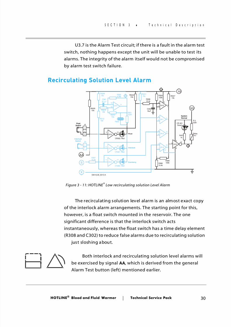
Recirculating Solution Level Alarm
The recirculating solution level alarm is an almost exact copyof the interlock alarm arrangements. The starting point for this,however, is a float switch mounted in the reservoir. The onesignificant difference is that the interlock switch acts
instantaneously, whereas the float switch has a time delay element(R308 and C302) to reduce false alarms due to recirculating solution
just sloshing about.
Both interlock and recirculating solution level alarms willbe exercised by signal AA , which is derived from the generalAlarm Test button (left) mentioned earlier.
FloatSwitch
Float
SystemNormal
Interlock Switch
Interlock
Overtemp
J3
J2
U4.2
U4.1
U4.3
U4.4
RelayK1
U3.3
Piezo
U3.2
U3.4
U3.5
U2.4
S
X
AA
10
VU
15
12
3
R305100k
R03/715k
R03/115k
R03/215k
R3028.2M
R30715.4k
R301722RR02/2
15k
R02/315k
R01/215k
R03/615k
R03/915k
R304100k
R30815.4k
R30615.4k
CR302 Red
CR301 Red
CR303 Red
R 2270RCR 401
Green
R4011k
C30210 Fµ
C3010.1 Fµ 3
2
14
4
13 6
5
12 7
10
1112
135
9
8
12
33
1
1
2
2 2
4
15
14
13
814
9
1
GM-HL90_8313-A
Figure 3 - 11: HOTLINE ® Low recirculating solution Level Alarm
8/13/2019 Smiths Fluid Warmer - General Technical Manual
http://slidepdf.com/reader/full/smiths-fluid-warmer-general-technical-manual 44/131
HOTLINE ® Blood and Fluid Warmer Technical Service Pack 31
S E C T I O N 3 T e c h n i c a l D e s c r i p t i o n
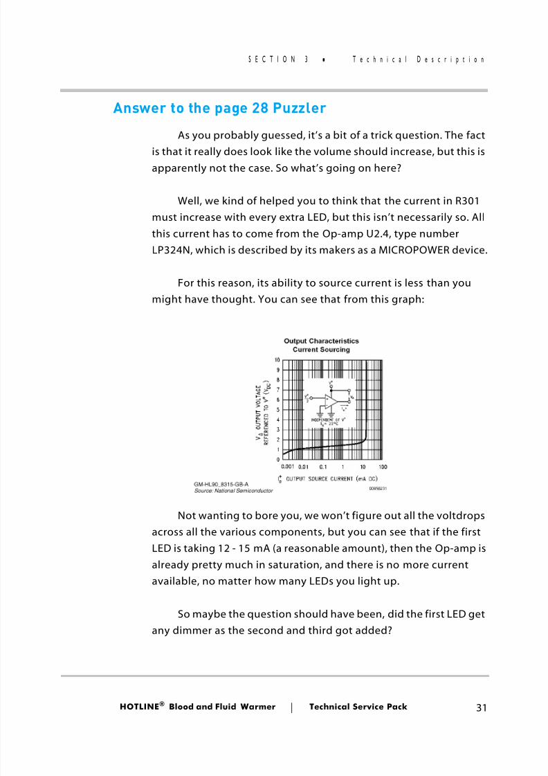
Answer to the page 28 Puzzler
As you probably guessed, it’s a bit of a trick question. The factis that it really does look like the volume should increase, but this isapparently not the case. So what’s going on here?
Well, we kind of helped you to think that the current in R301must increase with every extra LED, but this isn’t necessarily so. Allthis current has to come from the Op-amp U2.4, type numberLP324N, which is described by its makers as a MICROPOWER device.
For this reason, its ability to source current is less than youmight have thought. You can see that from this graph:
Not wanting to bore you, we won’t figure out all the voltdropsacross all the various components, but you can see that if the firstLED is taking 12 - 15 mA (a reasonable amount), then the Op-amp isalready pretty much in saturation, and there is no more currentavailable, no matter how many LEDs you light up.
So maybe the question should have been, did the first LED getany dimmer as the second and third got added?
8/13/2019 Smiths Fluid Warmer - General Technical Manual
http://slidepdf.com/reader/full/smiths-fluid-warmer-general-technical-manual 45/131
Disassembly Procedures
Blood andFluid Warmer
®
8/13/2019 Smiths Fluid Warmer - General Technical Manual
http://slidepdf.com/reader/full/smiths-fluid-warmer-general-technical-manual 46/131
HOTLINE ® Blood and Fluid Warmer Technical Service Pack 33
S E C T I O N 4 T o o l s y o u w i l l n e e d
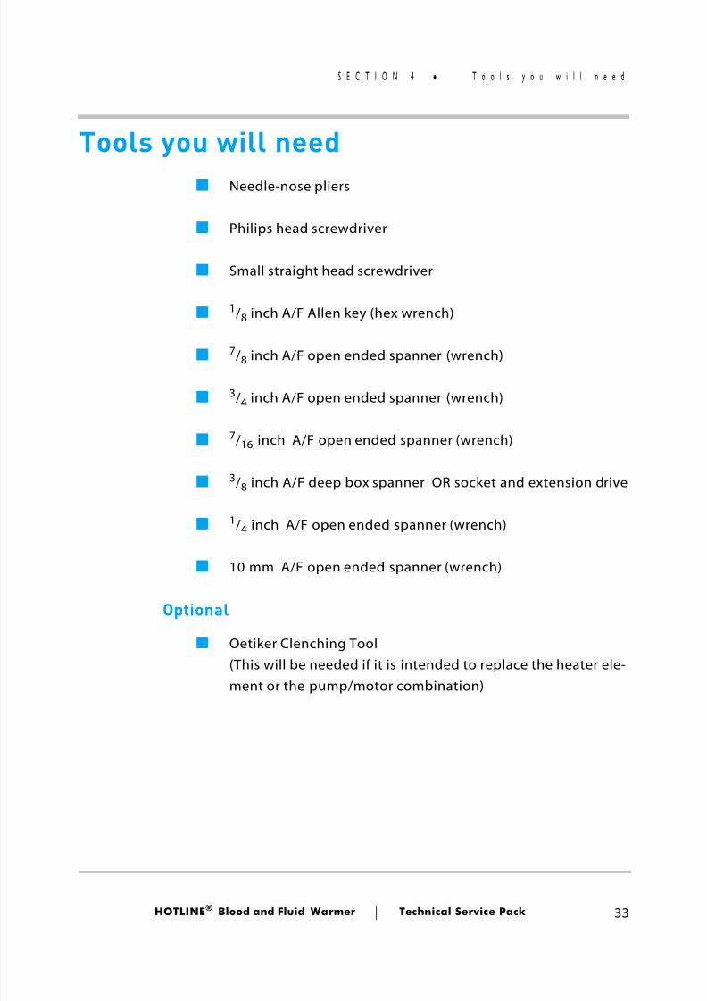
Tools you will need■ Needle-nose pliers
■ Philips head screwdriver
■ Small straight head screwdriver
■ 1/ 8 inch A/F Allen key (hex wrench)
■ 7/ 8 inch A/F open ended spanner (wrench)
■ 3/ 4 inch A/F open ended spanner (wrench)
■ 7/ 16 inch A/F open ended spanner (wrench)
■ 3/ 8 inch A/F deep box spanner OR socket and extension drive
■ 1/ 4 inch A/F open ended spanner (wrench)
■ 10 mm A/F open ended spanner (wrench)
Optional
■ Oetiker Clenching Tool(This will be needed if it is intended to replace the heater ele-ment or the pump/motor combination)
8/13/2019 Smiths Fluid Warmer - General Technical Manual
http://slidepdf.com/reader/full/smiths-fluid-warmer-general-technical-manual 47/131
HOTLINE ® Blood and Fluid Warmer Technical Service Pack 34
S E C T I O N 4 D i s a s s e m b l y
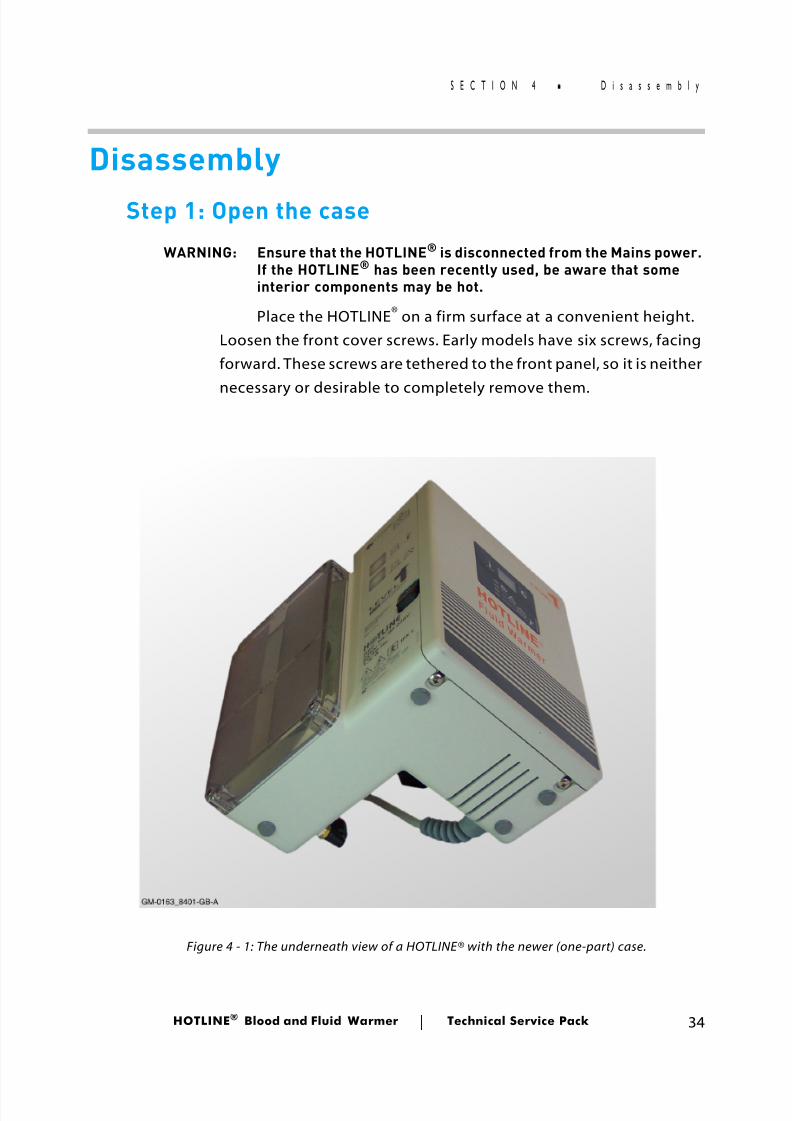
DisassemblyStep 1: Open the case
WARNING: Ensure that the HOTLINE ® is disconnected from the Mains power.If the HOTLINE® has been recently used, be aware that someinterior components may be hot.
Place the HOTLINE ® on a firm surface at a convenient height.Loosen the front cover screws. Early models have six screws, facingforward. These screws are tethered to the front panel, so it is neither
necessary or desirable to completely remove them.
Figure 4 - 1: The underneath view of a HOTLINE® with the newer (one-part) case.
8/13/2019 Smiths Fluid Warmer - General Technical Manual
http://slidepdf.com/reader/full/smiths-fluid-warmer-general-technical-manual 48/131
HOTLINE ® Blood and Fluid Warmer Technical Service Pack 35
S E C T I O N 4 D i s a s s e m b l y
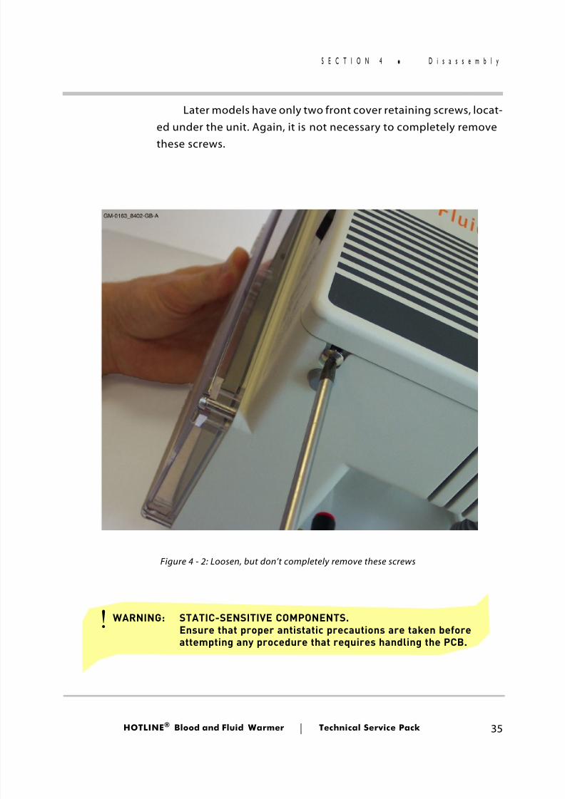
Later models have only two front cover retaining screws, locat-ed under the unit. Again, it is not necessary to completely removethese screws.
Figure 4 - 2: Loosen, but don’t completely remove these screws
WARNING: STATIC-SENSITIVE COMPONENTS.Ensure that proper antistatic precautions are taken beforeattempting any procedure that requires handling the PCB.
!
8/13/2019 Smiths Fluid Warmer - General Technical Manual
http://slidepdf.com/reader/full/smiths-fluid-warmer-general-technical-manual 49/131
HOTLINE ® Blood and Fluid Warmer Technical Service Pack 36
S E C T I O N 4 D i s a s s e m b l y
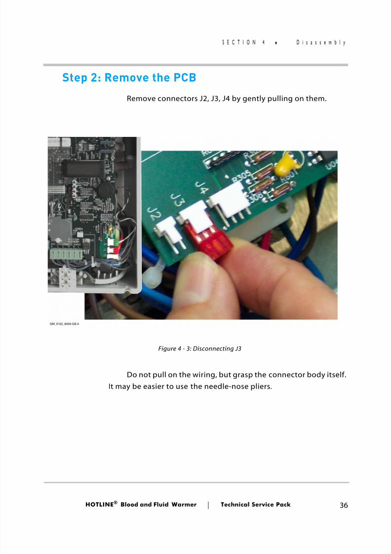
Step 2: Remove the PCB
Remove connectors J2, J3, J4 by gently pulling on them.
Do not pull on the wiring, but grasp the connector body itself.
It may be easier to use the needle-nose pliers.
Figure 4 - 3: Disconnecting J3
8/13/2019 Smiths Fluid Warmer - General Technical Manual
http://slidepdf.com/reader/full/smiths-fluid-warmer-general-technical-manual 50/131
HOTLINE ® Blood and Fluid Warmer Technical Service Pack 37
S E C T I O N 4 D i s a s s e m b l y
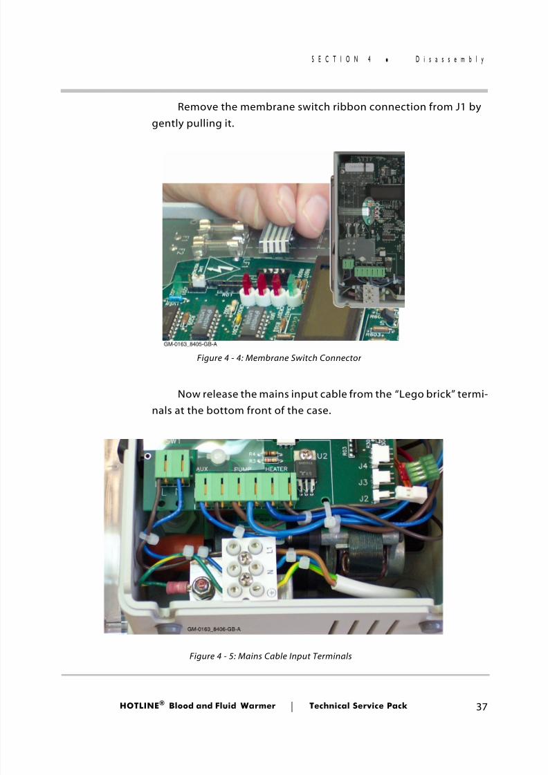
Remove the membrane switch ribbon connection from J1 bygently pulling it.
Now release the mains input cable from the “Lego brick” termi-nals at the bottom front of the case.
Figure 4 - 4: Membrane Switch Connector
Figure 4 - 5: Mains Cable Input Terminals
8/13/2019 Smiths Fluid Warmer - General Technical Manual
http://slidepdf.com/reader/full/smiths-fluid-warmer-general-technical-manual 51/131
HOTLINE ® Blood and Fluid Warmer Technical Service Pack 38
S E C T I O N 4 D i s a s s e m b l y
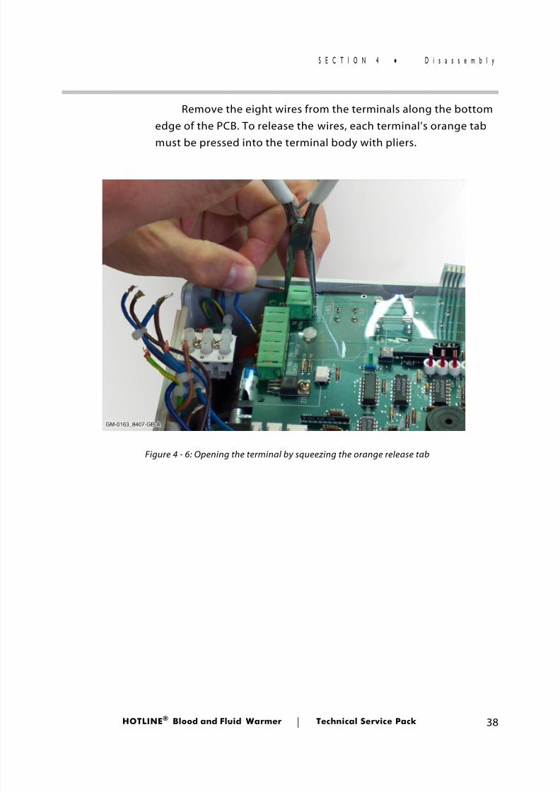
Remove the eight wires from the terminals along the bottomedge of the PCB. To release the wires, each terminal’s orange tabmust be pressed into the terminal body with pliers.
Figure 4 - 6: Opening the terminal by squeezing the orange release tab

8/13/2019 Smiths Fluid Warmer - General Technical Manual
http://slidepdf.com/reader/full/smiths-fluid-warmer-general-technical-manual 52/131
HOTLINE ® Blood and Fluid Warmer Technical Service Pack 39
S E C T I O N 4 D i s a s s e m b l y
Alternatively, the tabs may be manipulated with a smallstraight screwdriver through the slot on the terminal’s top surface.
Remove the four screws indicated.
GM-0163_8408-GB-A
(Only on older models)
1
2
3
4
Figure 4 - 7: PCB Mounting Points
Figure 4 - 8: Older versions have an additional fixing screw, making five in all.
8/13/2019 Smiths Fluid Warmer - General Technical Manual
http://slidepdf.com/reader/full/smiths-fluid-warmer-general-technical-manual 53/131
HOTLINE ® Blood and Fluid Warmer Technical Service Pack 40
S E C T I O N 4 D i s a s s e m b l y
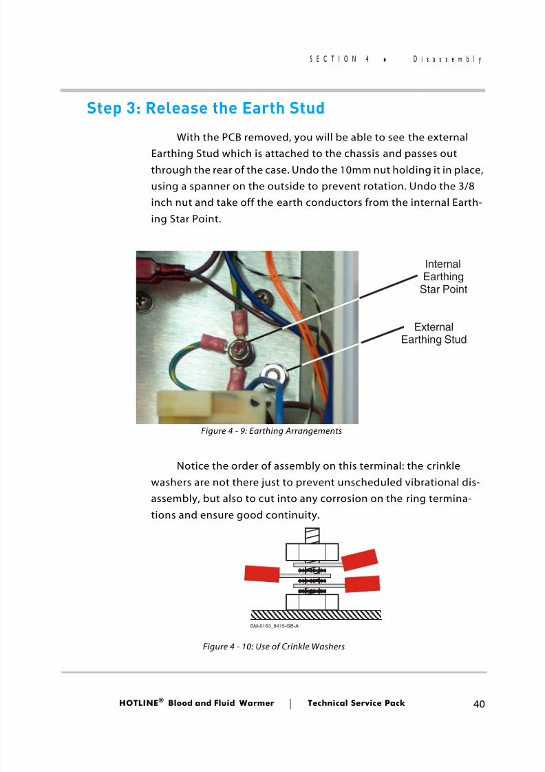
Step 3: Release the Earth Stud
With the PCB removed, you will be able to see the externalEarthing Stud which is attached to the chassis and passes outthrough the rear of the case. Undo the 10mm nut holding it in place,using a spanner on the outside to prevent rotation. Undo the 3/8inch nut and take off the earth conductors from the internal Earth-ing Star Point.
Notice the order of assembly on this terminal: the crinklewashers are not there just to prevent unscheduled vibrational dis-assembly, but also to cut into any corrosion on the ring termina-tions and ensure good continuity.
ExternalEarthing Stud
InternalEarthingStar Point
GM-0163_8415-GB-A
Figure 4 - 9: Earthing Arrangements
Figure 4 - 10: Use of Crinkle Washers
8/13/2019 Smiths Fluid Warmer - General Technical Manual
http://slidepdf.com/reader/full/smiths-fluid-warmer-general-technical-manual 54/131
HOTLINE ® Blood and Fluid Warmer Technical Service Pack 41
S E C T I O N 4 D i s a s s e m b l y
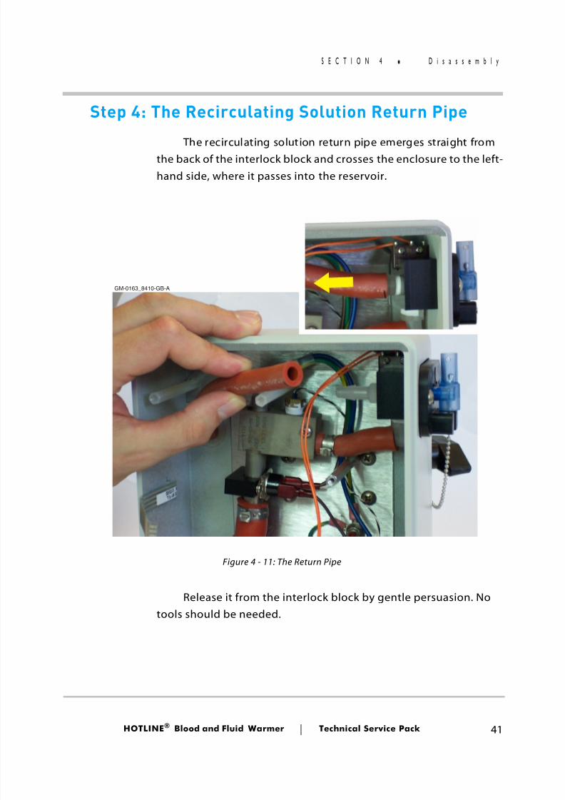
Step 4: The Recirculating Solution Return Pipe
The recirculating solution return pipe emerges straight fromthe back of the interlock block and crosses the enclosure to the left-hand side, where it passes into the reservoir.
Release it from the interlock block by gentle persuasion. Notools should be needed.
GM-0163_8410-GB-A
Figure 4 - 11: The Return Pipe
8/13/2019 Smiths Fluid Warmer - General Technical Manual
http://slidepdf.com/reader/full/smiths-fluid-warmer-general-technical-manual 55/131
HOTLINE ® Blood and Fluid Warmer Technical Service Pack 42
S E C T I O N 4 D i s a s s e m b l y
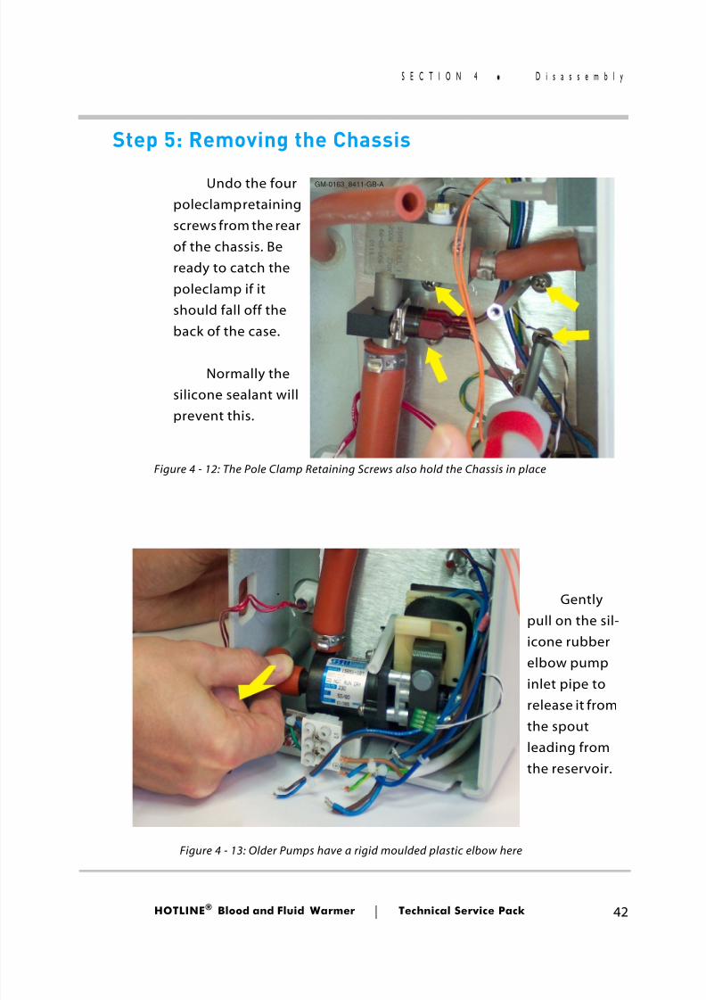
Step 5: Removing the Chassis
GM-0163_8411-GB-AUndo the fourpoleclamp retainingscrews from the rearof the chassis. Beready to catch thepoleclamp if itshould fall off theback of the case.
Normally thesilicone sealant willprevent this.
Gentlypull on the sil-icone rubberelbow pumpinlet pipe torelease it fromthe spoutleading fromthe reservoir.
Figure 4 - 12: The Pole Clamp Retaining Screws also hold the Chassis in place
Figure 4 - 13: Older Pumps have a rigid moulded plastic elbow here
8/13/2019 Smiths Fluid Warmer - General Technical Manual
http://slidepdf.com/reader/full/smiths-fluid-warmer-general-technical-manual 56/131
HOTLINE ® Blood and Fluid Warmer Technical Service Pack 43
S E C T I O N 4 D i s a s s e m b l y
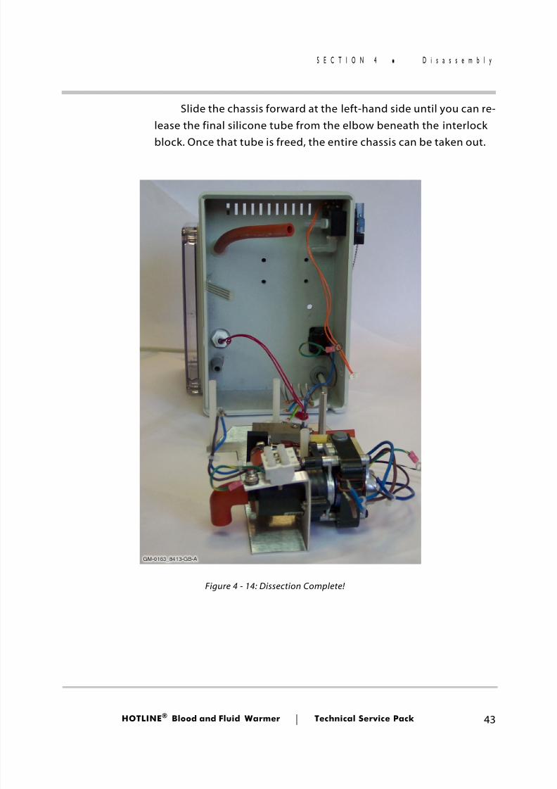
Slide the chassis forward at the left-hand side until you can re-lease the final silicone tube from the elbow beneath the interlockblock. Once that tube is freed, the entire chassis can be taken out.
Figure 4 - 14: Dissection Complete!
8/13/2019 Smiths Fluid Warmer - General Technical Manual
http://slidepdf.com/reader/full/smiths-fluid-warmer-general-technical-manual 57/131
HOTLINE ® Blood and Fluid Warmer Technical Service Pack 44
S E C T I O N 4 R e a s s e m b l y
ReassemblyReassembly is a s traightforward process, consisting of
following the aforementioned procedures in the reverse order.
Measurements
While you have the chance on a (presumed) good HOTLINE ®,
make a note of the following resistance measurements. They maybe useful when fault finding in future.
■ Pump Motor Coil (Specify March or GRI)
■ Heater Element
■ Transformer Primary
■ Relay K1 Coil
■ Display Thermistor (J4:1-2) (ambient temp)
■ Display Thermistor (J4:1-2) (operating temp)
■ Control Thermistor (J4: 3-4) (ambient temp)
■Control Thermistor (J4: 3-4) (operating temp)
8/13/2019 Smiths Fluid Warmer - General Technical Manual
http://slidepdf.com/reader/full/smiths-fluid-warmer-general-technical-manual 58/131
Blood andFluid Warmer
®
Maintenance, Testingand Calibration
8/13/2019 Smiths Fluid Warmer - General Technical Manual
http://slidepdf.com/reader/full/smiths-fluid-warmer-general-technical-manual 59/131
HOTLINE ® Blood and Fluid Warmer Technical Service Pack 46
S E C T I O N 5 M a i n t e n a n c e
MaintenanceBefore each use
Carefully inspect the HOTLINE ® for signs of damage, cracked orsplit case, insecure poleclamp, damaged mains cable, etc.
If the Disposable Set does not install easily, lubricate the O-Ring Seals.
Lubricating the O-Ring SealsUsing a cotton swab, apply a small amount of silicone grease
(Smiths Medical Part Number EZL 80-04-002) to the O-Rings in theDisposable Set connector block.
If this does not solve the problem, reject the unit.
After each useWipe all external surfaces of the HOTLINE ® with a soft cloth,
using an aqueous solution of mild detergent. If necessary, theexternal surfaces may be disinfected using a solution of 10% bleachin distilled water.
■ Do not autoclave.
■ Do not use alcohol or solvents.
■ Do not use abrasive cleaning agents.
■ Do not use cold sterilants.
■ Do not immerse any part of the HOTLINE ® in liquids.
8/13/2019 Smiths Fluid Warmer - General Technical Manual
http://slidepdf.com/reader/full/smiths-fluid-warmer-general-technical-manual 60/131
8/13/2019 Smiths Fluid Warmer - General Technical Manual
http://slidepdf.com/reader/full/smiths-fluid-warmer-general-technical-manual 61/131
HOTLINE ® Blood and Fluid Warmer Technical Service Pack 48
S E C T I O N 5 E v e r y 3 0 d a y s
Every 30 days■ Perform a Visual Inspection looking for damage to the case,
poleclamp, mains cable, etc.
■ Lubricate O-Ring Seals with a cotton swab, applying a smallamount of silicone grease to the O-Rings.
Either, if using DISTILLED WATER as therecirculating solution:
■ Drain and replace the recirculating solution as described onpage 54.
or, if using ISOPROPYL ALCOHOL as therecirculating solution:
■ Drain and replace the recirculating solution as described onpage 56.
Finally
■ Fill in, sign, and date the maintenance log record!
8/13/2019 Smiths Fluid Warmer - General Technical Manual
http://slidepdf.com/reader/full/smiths-fluid-warmer-general-technical-manual 62/131
HOTLINE ® Blood and Fluid Warmer Technical Service Pack 49
S E C T I O N 5 E v e r y 1 2 M o n t h s
Every 12 Months
Alarm Testing
Place the HOTLINE ® on a suitable firm surface. Visually checkthat the recirculating solution level in the reservoir is above the MINmark. Attach a Disposable Set, ensuring that it is free from kinks andtwists.
Plug the unit into the electricity supply and switch on. Verifythat the unit is working normally (recirculating solution circulating,temperature display gradually rising towards 41°C).
General Alarm Test
Press the General Alarm Test button. Observe:
■ the GREEN LED extinguishes.
■ the THREE RED LEDs light up.
■ the AUDIBLE ALARM commences beeping.
■ the RECIRCULATING SOLUTION ceases circulating.
If any of the above responses are missing, the unit must beremoved from service and repaired.
8/13/2019 Smiths Fluid Warmer - General Technical Manual
http://slidepdf.com/reader/full/smiths-fluid-warmer-general-technical-manual 63/131
HOTLINE ® Blood and Fluid Warmer Technical Service Pack 50
S E C T I O N 5 E v e r y 1 2 M o n t h s
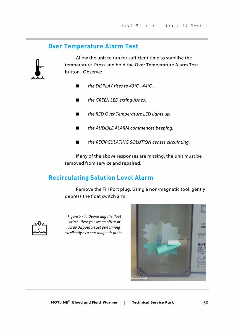
Over Temperature Alarm Test
Allow the unit to run for sufficient time to stabilise thetemperature. Press and hold the Over Temperature Alarm Testbutton. Observe:
■ the DISPLAY rises to 43°C - 44°C .
■ the GREEN LED extinguishes.
■ the RED Over Temperature LED lights up.
■ the AUDIBLE ALARM commences beeping.
■ the RECIRCULATING SOLUTION ceases circulating.
If any of the above responses are missing, the unit must beremoved from service and repaired.
Recirculating Solution Level Alarm
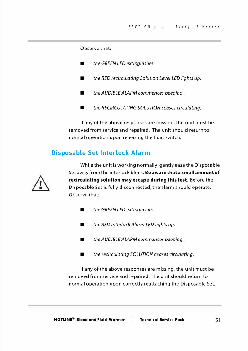
Remove the Fill Port plug. Using a non-magnetic tool, gentlydepress the float switch arm.
Figure 5 - 1: Depressing the float switch. Here you see an offcut of scrap Disposable Set performing
excellently as a non-magnetic probe.
8/13/2019 Smiths Fluid Warmer - General Technical Manual
http://slidepdf.com/reader/full/smiths-fluid-warmer-general-technical-manual 64/131
HOTLINE ® Blood and Fluid Warmer Technical Service Pack 51
S E C T I O N 5 E v e r y 1 2 M o n t h s
Observe that:
■ the GREEN LED extinguishes.
■ the RED recirculating Solution Level LED lights up.
■ the AUDIBLE ALARM commences beeping.
■ the RECIRCULATING SOLUTION ceases circulating.
If any of the above responses are missing, the unit must beremoved from service and repaired. The unit should return tonormal operation upon releasing the float switch.
Disposable Set Interlock Alarm
While the unit is working normally, gently ease the DisposableSet away from the interlock block. Be aware that a small amount ofrecirculating solution may escape during this test. Before theDisposable Set is fully disconnected, the alarm should operate.Observe that:
■ the GREEN LED extinguishes.
■ the RED Interlock Alarm LED lights up.
■ the AUDIBLE ALARM commences beeping.
■ the recirculating SOLUTION ceases circulating.
If any of the above responses are missing, the unit must beremoved from service and repaired. The unit should return tonormal operation upon correctly reattaching the Disposable Set.
8/13/2019 Smiths Fluid Warmer - General Technical Manual
http://slidepdf.com/reader/full/smiths-fluid-warmer-general-technical-manual 65/131
HOTLINE ® Blood and Fluid Warmer Technical Service Pack 52
S E C T I O N 5 E v e r y 1 2 M o n t h s
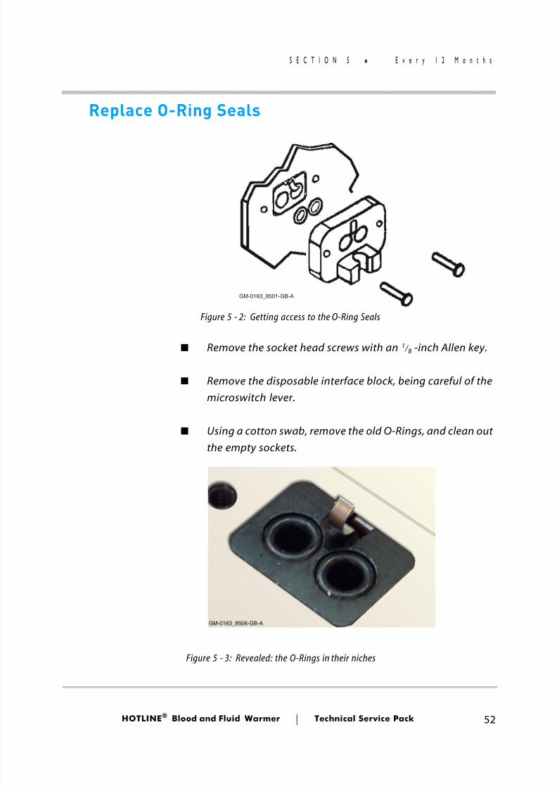
Replace O-Ring Seals
■ Remove the socket head screws with an 1 / 8 -inch Allen key.
■ Remove the disposable interface block, being careful of themicroswitch lever.
■ Using a cotton swab, remove the old O-Rings, and clean outthe empty sockets.
GM-0163_8501-GB-A
Figure 5 - 3: Revealed: the O-Rings in their niches
Figure 5 - 2: Getting access to the O-Ring Seals
8/13/2019 Smiths Fluid Warmer - General Technical Manual
http://slidepdf.com/reader/full/smiths-fluid-warmer-general-technical-manual 66/131
HOTLINE ® Blood and Fluid Warmer Technical Service Pack 53
S E C T I O N 5 E v e r y 1 2 M o n t h s
■ Apply a smear of silicone grease (Smiths Medical PartNumber EZL 80-04-002) to two new O-Rings, and locatethem in the sockets.
■ Re-attach the disposable interface block.
■ Re-fit the socket head screws. Again, take care not todamage or bend the microswitch operating lever.
A kit of parts is available to make this task simpler. Please ask for
part number reference EZL 80-04-001.
Either, if using DISTILLED WATER as therecirculating solution:
■ Drain and replace the recirculating solution as described onpage 54.
or, if using ISOPROPYL ALCOHOL as therecirculating solution:
■ Drain and replace the recirculating solution as described onpage 56.
or, if using HYDROGEN PEROXIDE as therecirculating solution:
■ Drain and replace the recirculating solution as described onpage 57.
Finally
■ Fill in, sign, and date the maintenance log record!
8/13/2019 Smiths Fluid Warmer - General Technical Manual
http://slidepdf.com/reader/full/smiths-fluid-warmer-general-technical-manual 67/131
HOTLINE ® Blood and Fluid Warmer Technical Service Pack 54
S E C T I O N 5 M a i n t e n a n c e S o l u t i o n s
Changing Recirculating Solution (Distilled Water)
If using plain distilled water as the recirculating fluid, then thismust be changed at the 30-day service interval, using the proceduregiven here. Smiths Medical currently recommends using theHydrogen Peroxide based recirculating solution which allows a12-monthly recirculating solution change protocol, resulting in asignificant reduction of service time.
Maintenance SolutionsAt service intervals of either 12-months or 30-days, depending on the
composition of your recirculating solution, you will need supplies of ready mixedsolutions to perform maintenance. To make up a batch (1.4 litres) of solution, youwill need:
Formula 1
140ml of 3% Hydrogen Peroxide PLUS 1260ml distilled water
This may be used as a disinfectant fluid for flushing the recirculating solutionpath during routine maintenance, or as a long-life recirculating solution enablingfluid change intervals to be extended to 12-monthly.
Formula 2
700ml of 70% Isopropyl Alcohol PLUS 700ml distilled water
This may be used as a disinfectant fluid for flushing the recirculatingsolution path during routine maintenance, or as a recirculating solution. It is NOTsuitable for long-term use, and must be replaced at 30-day intervals.
8/13/2019 Smiths Fluid Warmer - General Technical Manual
http://slidepdf.com/reader/full/smiths-fluid-warmer-general-technical-manual 68/131
HOTLINE ® Blood and Fluid Warmer Technical Service Pack 55
S E C T I O N 5 M a i n t e n a n c e S o l u t i o n s
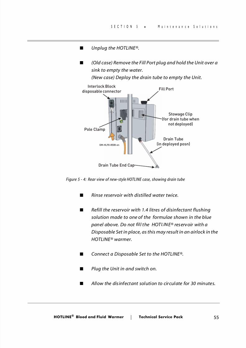
■ Unplug the HOTLINE®.
■ (Old case) Remove the Fill Port plug and hold the Unit over asink to empty the water.(New case) Deploy the drain tube to empty the Unit.
■ Rinse reservoir with distilled water twice.
■ Refill the reservoir with 1.4 litres of disinfectant flushingsolution made to one of the formulae shown in the blue panel above. Do not fill the HOTLINE® reservoir with aDisposable Set in place, as this may result in an airlock in theHOTLINE® warmer.
■ Connect a Disposable Set to the HOTLINE®.
■ Plug the Unit in and switch on.
■ Allow the disinfectant solution to circulate for 30 minutes.
Drain Tube(in deployed posn)
Drain Tube End Cap
Fill Port
Pole Clamp
Interlock Blockdisposable connector
Stowage Clip(for drain tube when
not deployed)
GM-HL90-8508-en
Figure 5 - 4: Rear view of new-style HOTLINE case, showing drain tube
8/13/2019 Smiths Fluid Warmer - General Technical Manual
http://slidepdf.com/reader/full/smiths-fluid-warmer-general-technical-manual 69/131
HOTLINE ® Blood and Fluid Warmer Technical Service Pack 56
S E C T I O N 5 M a i n t e n a n c e S o l u t i o n s
■ Switch off and disconnect the Unit.
■ Empty the unit once more.
■ Rinse reservoir with distilled water again.
■ Refill the unit with 1.4 litres of sterile distilled water.
■ Replace the Fill Port plug.
NOTE: Unless using one of the approved maintenance solutions, use onlysterile distilled or de-ionised water. Failure to do so may lead to abuild-up of mineral deposits in the recirculating solution path whichmay impair heater performance.
Changing Recirculating Solution (Isopropyl Alcohol)
Since the Isopropyl Alcohol solution gradually loses potency,it must be replaced at the 30-day service interval using the
following procedure:
■ Prepare two batches of 1.4 litres of recirculating solutionaccording to formula 2 above for 35% Isopropyl Alcoholmaintenance solution.
■ Drain the HOTLINE®, and refill with one of the preparedbatches.
■ Install an L-70 or L-70 NI Disposable Administration Set inthe HOTLINE®’s Disposable Set connector.
■ Turn on the HOTLINE® and allow the fresh fluid to circulatefor 30 minutes.
8/13/2019 Smiths Fluid Warmer - General Technical Manual
http://slidepdf.com/reader/full/smiths-fluid-warmer-general-technical-manual 70/131
HOTLINE ® Blood and Fluid Warmer Technical Service Pack 57
S E C T I O N 5 M a i n t e n a n c e S o l u t i o n s
■ Switch off the HOTLINE® and dispose of the Disposable Setin accordance with the usual procedures for yourestablishment. Drain the Fluid from the HOTLINE® anddiscard.
■ Refill the HOTLINE® with the second of the Isopropyl Alcoholsolution batches you made earlier.
NOTE: If the HOTLINE ® requires topping up at any time before the nextroutine recirculating solution change, make sure you always use thecorrect mix of Isopropyl Alcohol and Distilled water.
Changing Recirculating Solution (Hydrogen Peroxide)
At the annual routine service interval the Hydrogen Peroxidesolution must be replaced as follows:
■ Prepare two batches of 1.4 litres of recirculating solution
according to formula 1 above for 0.3% Hydrogen Peroxidemaintenance solution.
■ Drain the HOTLINE®, and refill with one of the preparedbatches.
■ Install an L-70 or L-70 NI Disposable Administration Set inthe HOTLINE®’s Disposable Set connector.
■ Turn on the HOTLINE® and allow the fresh fluid to circulatefor 30 minutes.
■ Switch off the HOTLINE® and dispose of the Disposable Setin accordance with the usual procedures for your
8/13/2019 Smiths Fluid Warmer - General Technical Manual
http://slidepdf.com/reader/full/smiths-fluid-warmer-general-technical-manual 71/131
HOTLINE ® Blood and Fluid Warmer Technical Service Pack 58
S E C T I O N 5 M a i n t e n a n c e S o l u t i o n s
establishment. Drain the fluid from the HOTLINE® anddiscard.
■ Refill the HOTLINE® with the second of the recirculatingsolution batches you made earlier.
NOTE: If the HOTLINE ® requires topping up at any time before the nextroutine recirculating solution change, make sure you always use thecorrect mix of Hydrogen Peroxide and Distilled water.
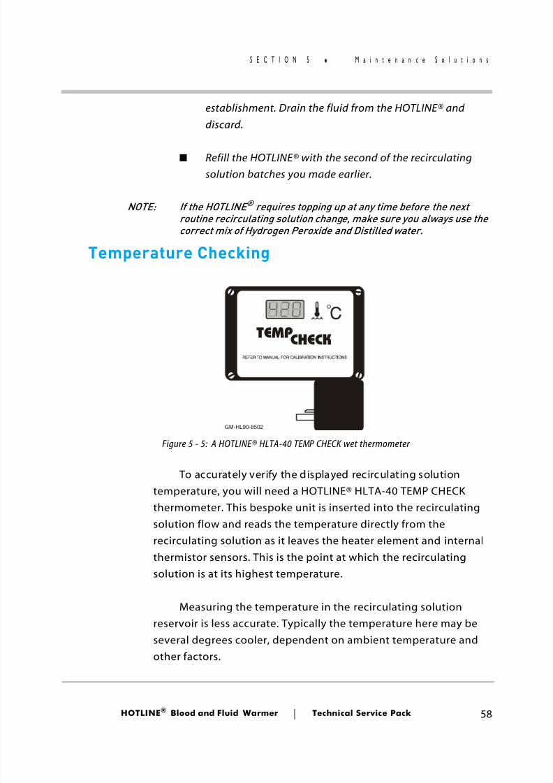
Temperature Checking
To accurately verify the displayed recirculating solutiontemperature, you will need a HOTLINE® HLTA-40 TEMP CHECKthermometer. This bespoke unit is inserted into the recirculatingsolution flow and reads the temperature directly from the
recirculating solution as it leaves the heater element and internalthermistor sensors. This is the point at which the recirculatingsolution is at its highest temperature.
Measuring the temperature in the recirculating solutionreservoir is less accurate. Typically the temperature here may beseveral degrees cooler, dependent on ambient temperature andother factors.
TEMPCHECK
GM-HL90-8502
Figure 5 - 5: A HOTLINE® HLTA-40 TEMP CHECK wet thermometer
8/13/2019 Smiths Fluid Warmer - General Technical Manual
http://slidepdf.com/reader/full/smiths-fluid-warmer-general-technical-manual 72/131
HOTLINE ® Blood and Fluid Warmer Technical Service Pack 59
S E C T I O N 5 M a i n t e n a n c e S o l u t i o n s
If you do not have a HOTLINE® TEMP CHECK thermometer,units may be returned to Smiths Medical for temperatureverification.
Set up the HOTLINE® ready for use as before. Attach the TEMPCHECK thermometer to the interlock block of the HOTLINE® andconnect the Disposable Set to the TEMP CHECK .
Carefully unpeel the black sticker from the back of theHOTLINE®, and loosely attach it in a safe place ready for re-use. Plug
the TEMP CHECK ’s Mains cable into the Auxiliary Outlet socket ofthe HOTLINE®.
NOTE: The Auxiliary Outlet is for use only with approved accessoriessupplied by your Smiths Medical distributor for that purpose.
Run the HOTLINE® for 15 minutes to allow the temperature to
stabilise. Verify that:
■ the TEMP CHECK indicates a recirculating solution tempera-ture between 41°C and 42°C
■ The HOTLINE®’s display indicates the same temperature.
If either of these conditions is not met, the unit will requireeither recalibration or repairing and recalibration before it can bereturned to active service.
If both conditions are satisfied, dismantle the test assembly,and replace the black sticker over the Aux socket. Document thedate and results of your tests and return the HOTLINE® to activeservice.
8/13/2019 Smiths Fluid Warmer - General Technical Manual
http://slidepdf.com/reader/full/smiths-fluid-warmer-general-technical-manual 73/131
HOTLINE ® Blood and Fluid Warmer Technical Service Pack 60
S E C T I O N 5 R o u t i n e M a i n t e n a n c e C h e c k l i s
Routine Maintenance ChecklistsYou may freely photocopy the checklists on the next three
pages to act as a continuing record of your routine HOTLINE® HL-90maintenance.
The correct checklis t to use is dependent on the choice ofprotocol used for maintenance on the HOTLINE®s in your care. Ifyou choose to stick to the traditional distilled water recirculatingsolution, you will need the first checklist. This allows for thechanging of the recirculating solution on a monthly cycle.
Otherwise, the third checklist corresponds with SmithsMedical’s recommended protocol of having a 12-month intervalbetween solution changes, and using a disinfectant mixture as therecirculating solution on a permanent basis.
In some territories, Hydrogen Peroxide may not be readily
available, or it may be that it is not included in the establishment’spreferred protocols. If that is the case, and it is still necessary tomaintain a disinfectant recirculating solution, then the secondchecklist gives the correct pattern when using Isopropyl Alcoholsolution with a 30-day replacement cycle. It is not permitted to usethe Isopropyl Alcohol solution on a 12-monthly replacement cycleas it loses its potency much more rapidly than the recommendedHydrogen Peroxide solution. For this reason, batches of Isopropyl
Alcohol solution (Formula 2) should ideally be freshly mixedimmediately before use.
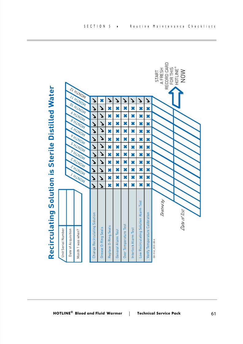
8/13/2019 Smiths Fluid Warmer - General Technical Manual
http://slidepdf.com/reader/full/smiths-fluid-warmer-general-technical-manual 74/131
HOTLINE ® Blood and Fluid Warmer Technical Service Pack 61
S E C T I O N 5 R o u t i n e M a i n t e n a n c e C h e c k l i s
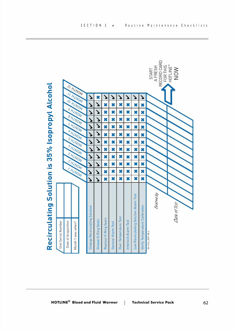
8/13/2019 Smiths Fluid Warmer - General Technical Manual
http://slidepdf.com/reader/full/smiths-fluid-warmer-general-technical-manual 75/131
HOTLINE ® Blood and Fluid Warmer Technical Service Pack 62
S E C T I O N 5 R o u t i n e M a i n t e n a n c e C h e c k l i s
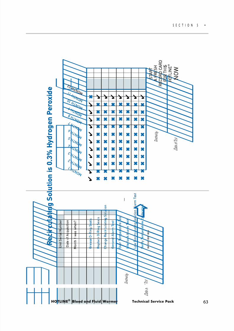
8/13/2019 Smiths Fluid Warmer - General Technical Manual
http://slidepdf.com/reader/full/smiths-fluid-warmer-general-technical-manual 76/131
HOTLINE ® Blood and Fluid Warmer Technical Service Pack 63
S E C T I O N 5
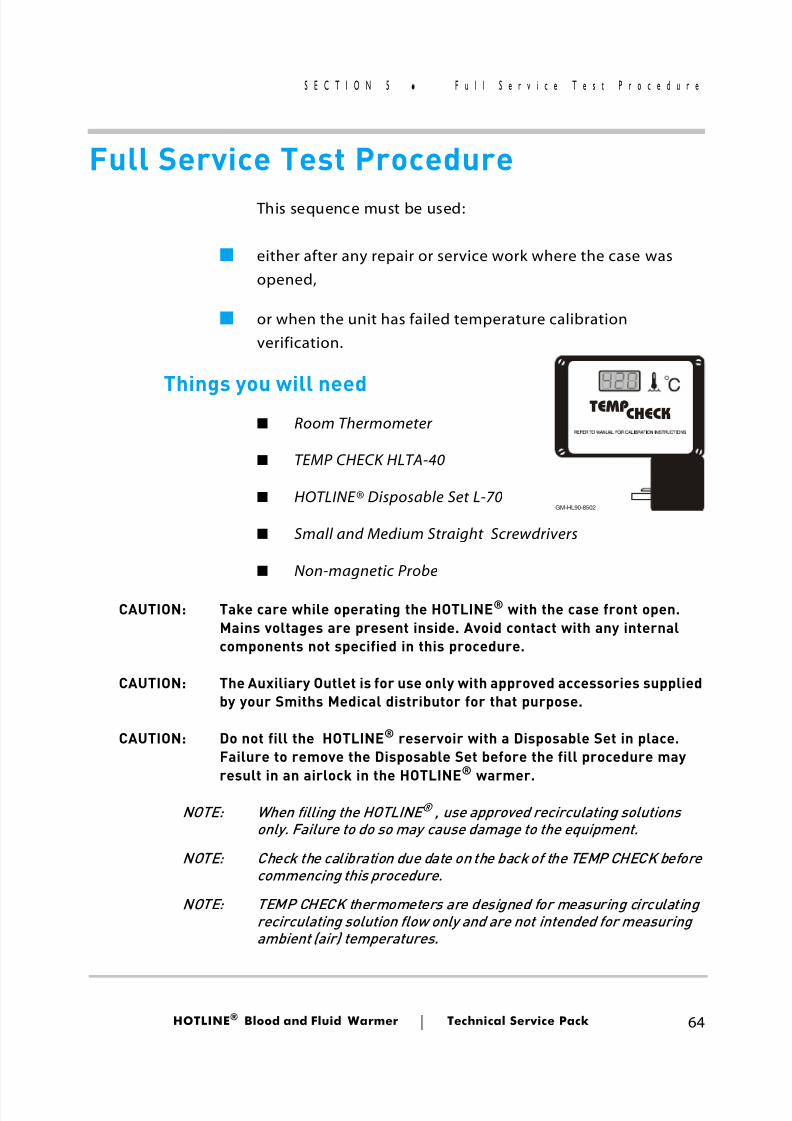
8/13/2019 Smiths Fluid Warmer - General Technical Manual
http://slidepdf.com/reader/full/smiths-fluid-warmer-general-technical-manual 77/131
HOTLINE ® Blood and Fluid Warmer Technical Service Pack 64
S E C T I O N 5 F u l l S e r v i c e T e s t P r o c e d u r e
Full Service Test Procedure This sequence must be used:
■ either after any repair or service work where the case wasopened,
■ or when the unit has failed temperature calibrationverification.
Things you will need■ Room Thermometer
■ TEMP CHECK HLTA-40
■ HOTLINE® Disposable Set L-70
■ Small and Medium Straight Screwdrivers
■ Non-magnetic Probe
CAUTION: Take care while operating the HOTLINE ® with the case front open.Mains voltages are present inside. Avoid contact with any internalcomponents not specified in this procedure.
CAUTION: The Auxiliary Outlet is for use only with approved accessories suppliedby your Smiths Medical distributor for that purpose.
CAUTION: Do not fill the HOTLINE® reservoir with a Disposable Set in place.Failure to remove the Disposable Set before the fill procedure may
result in an airlock in the HOTLINE®
warmer.
NOTE: When filling the HOTLINE ® , use approved recirculating solutionsonly. Failure to do so may cause damage to the equipment.
NOTE: Check the calibration due date on the back of the TEMP CHECK beforecommencing this procedure.
NOTE: TEMP CHECK thermometers are designed for measuring circulatingrecirculating solution flow only and are not intended for measuringambient (air) temperatures.
TEMP CHECK
GM-HL90-8502
8/13/2019 Smiths Fluid Warmer - General Technical Manual
http://slidepdf.com/reader/full/smiths-fluid-warmer-general-technical-manual 78/131
HOTLINE ® Blood and Fluid Warmer Technical Service Pack 65
S E C T I O N 5 H L - 9 0 S e r v i c e T e s t S p e c i f i c a t i
HL-90 Service Test SpecificationSetup
[i] Fill unit up with de-ionised water, attach an L-70Disposable Set, turn on and let the HOTLINE® run for 40minutes minimum.
[ii] Check that the Ambient Room Temperature is22.0°C ± 2.0°C. If the temperature is out of this specifiedrange, do NOT proceed with this calibration procedure.
[iii] Remove the Disposable Set, install the Temp Check to theunit, and re-attach the Disposable Set.
[iv] Remove case front. Confirm that J201 is in the “40” position.(See Appendix 2)
Check For Leaks
[i] Observe that the fluid is circulating in the HOTLINE®reservoir.
[ii] Check all fittings and seams in the recirculating system forleaks.
Interlock Switch Test
[i] Slowly release the Temp Check from the interlock switch. Asmall amount of recirculating fluid may escape. The alarmshould activate.
[ii] Return the Temp Check to the interlock switch. Unit shouldreturn to being operational.
8/13/2019 Smiths Fluid Warmer - General Technical Manual
http://slidepdf.com/reader/full/smiths-fluid-warmer-general-technical-manual 79/131
HOTLINE ® Blood and Fluid Warmer Technical Service Pack 66
S E C T I O N 5 H L - 9 0 S e r v i c e T e s t S p e c i f i c a t i
Alarm Test Switch
[i] Depress the General Alarm Test switch.
[ii] The “Operational” or “Warming” LED should turn off. All“Alarm” LED’s should be flashing and the alarm must beaudible.
[iii] Release switch and the system should become operationalagain.
Check Float Switch[i] To check float switch, remove the fill port cap and depress
the float switch (which is located inside the reservoir) with anon-magnetic float switch probe.
[ii] The “Recirculating Solution Level” warning LED should lightand the alarm will be audible. The Green “Operational” LEDand the pump should turn off.
[iii] Release the float switch and the system will once morebecome operational.
Set Recirculating Solution Temperature
Used to align the displayedtemperature with the actualwater temperature
LCD
O TEMP
H2O
Adjusts the set point forthe Over Temperature Alarm
Sets the operating point ofthe temperature control circuit.On older pumps this may belabelled “40” as shown here.
LVL1-HL90_8504-GB-A
Figure 5 - 6: Purpose of the Pots
8/13/2019 Smiths Fluid Warmer - General Technical Manual
http://slidepdf.com/reader/full/smiths-fluid-warmer-general-technical-manual 80/131
HOTLINE ® Blood and Fluid Warmer Technical Service Pack 67
S E C T I O N 5 H L - 9 0 S e r v i c e T e s t S p e c i f i c a t i
[i] If necessary, turn the “H2O” or “40” temperature set pointadjustment pot clockwise to increase recirculating solution
temperature, or counter-clockwise to decrease recirculatingsolution temperature. A quarter turn of the pot correspondsto a change in temperature of about 0.3°C. Allow 5 minutesbetween adjustments for the temperature to stabilise .
[ii] Set unit to run at 41.9°C ± 0.1°C as measured by the TEMPCHECK and allow to stabilise.
Set Over Temperature Alarm Set Point
[i] Adjust the “LCD” adjustment pot so the LCD reads 43.1°C. Ifthe alarm activates before the display reaches 43.1, thenadjust the over temperature pot clockwise until the alarmturns off and continue adjusting LCD.
[ii] Adjust the over temperature pot counter-clockwise until thealarm sounds.
[iii] Adjust the “LCD” adjustment pot counter-clockwise andconfirm that the alarm deactivates.
[iv] Adjust the “LCD” adjustment pot clockwise again andconfirm that the alarm activates at 43.1°C.
[v] Repeat the test twice to confirm the activation set point.
Calibrate LCD
[i] Turn the “LCD” adjustment pot on the PCB so that the unitdisplay (LCD) is equal to the that of the Temp Check ± 0.0°C.
[ii] To confirm the Over Temperature Alarm, depress and holdthe over temperature switch on the side of the enclosure.
8/13/2019 Smiths Fluid Warmer - General Technical Manual
http://slidepdf.com/reader/full/smiths-fluid-warmer-general-technical-manual 81/131
HOTLINE ® Blood and Fluid Warmer Technical Service Pack 68
S E C T I O N 5 H L - 9 0 S e r v i c e T e s t S p e c i f i c a t i
[iii] The PCB display should increase to 43.6°C ± 0.3°C and thenthe Over Temperature Alarm should activate. Release and
the unit should return to normal operation.
[iv] Attach and close the case front.
Idle Check
[i] Allow the unit to run at 41.9°C ± 0.1°C for 15 minutes andconfirm that the display is stable for a further 5 minutes.
[ii] Record the ambient room temperature which should be
22.0°C ± 2.0°C. If it is out of this range you can not completethis calibration. You must start a fresh calibrationsequence.
Safety Test
[i] Safety test the HOTLINE ® in accordance with the ElectricalSafety Testing System normally used by your establishment.
Test Completion
[i] Drain the distilled water and refill unit with 1.4 litres ofeither fresh sterile distilled water or whatever formula is theusual establishment practice.
[ii] Verify that the Service History record has been completed.Clean case and return to service.
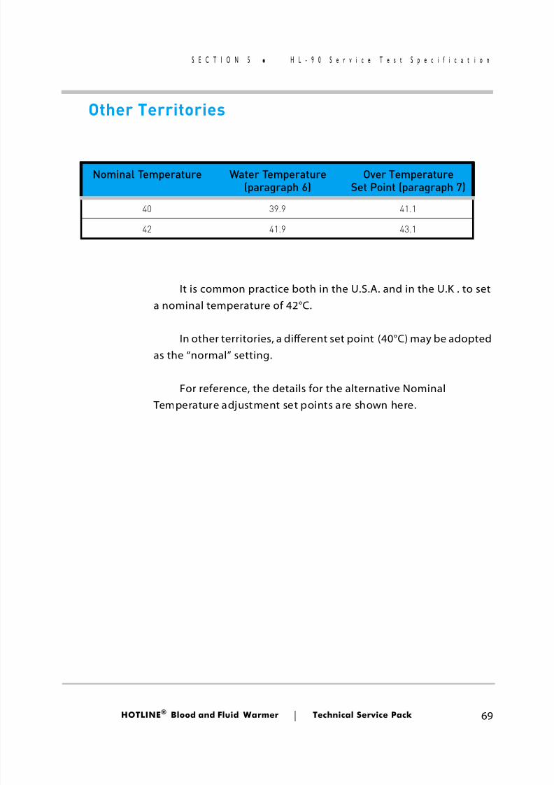
8/13/2019 Smiths Fluid Warmer - General Technical Manual
http://slidepdf.com/reader/full/smiths-fluid-warmer-general-technical-manual 82/131
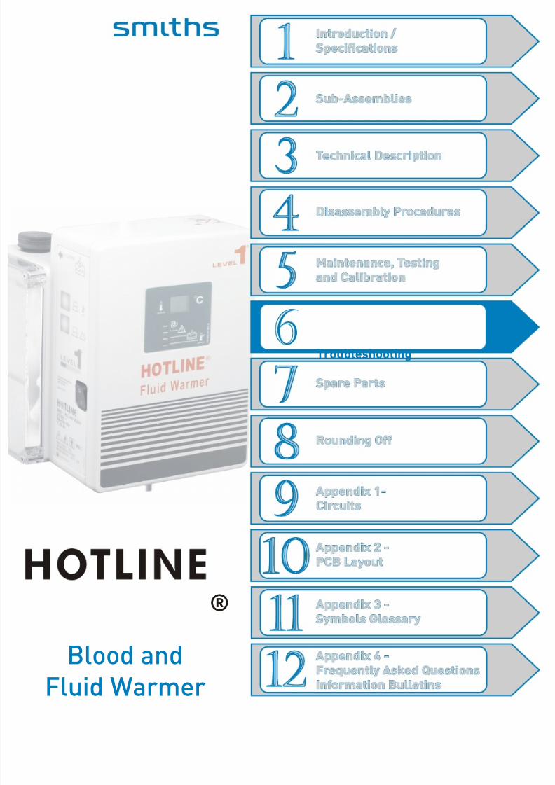
8/13/2019 Smiths Fluid Warmer - General Technical Manual
http://slidepdf.com/reader/full/smiths-fluid-warmer-general-technical-manual 83/131
Troubleshooting
Blood andFluid Warmer
®
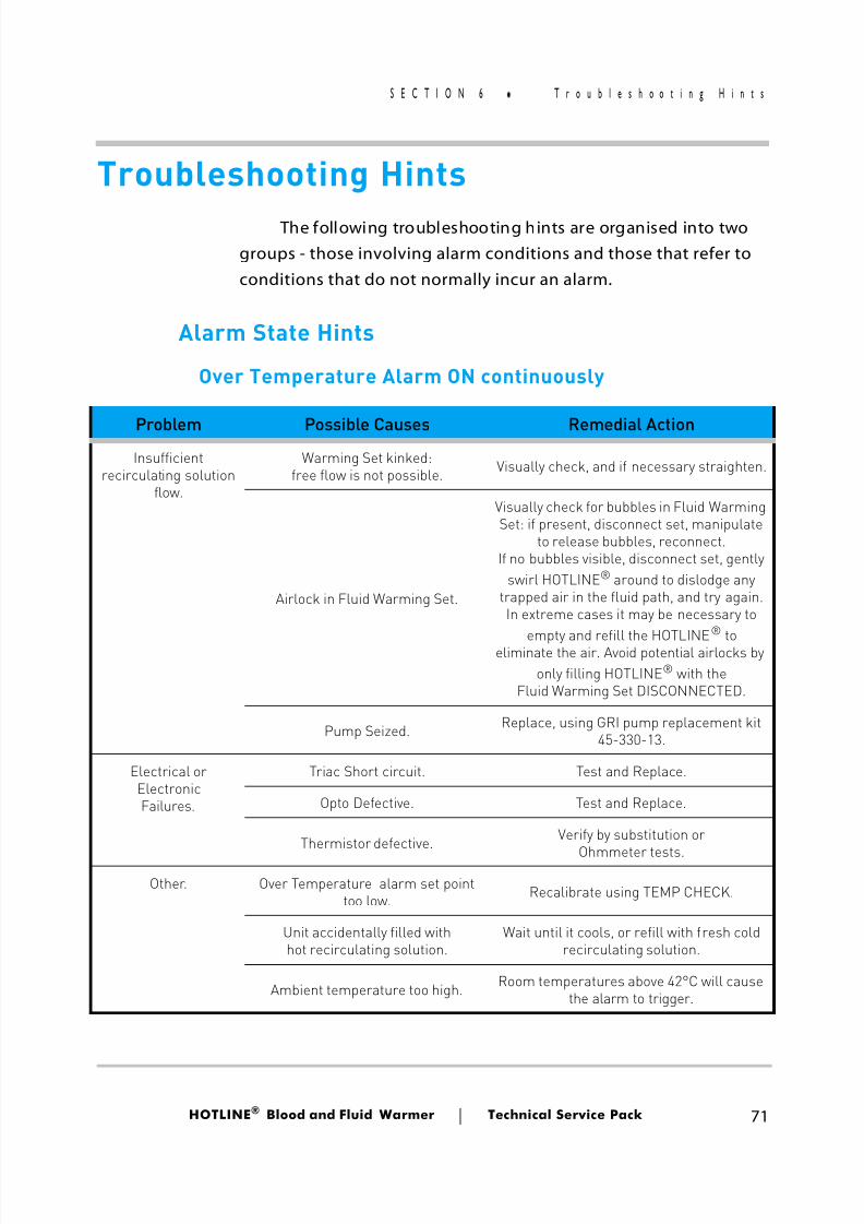
8/13/2019 Smiths Fluid Warmer - General Technical Manual
http://slidepdf.com/reader/full/smiths-fluid-warmer-general-technical-manual 84/131
HOTLINE ® Blood and Fluid Warmer Technical Service Pack 71
S E C T I O N 6 T r o u b l e s h o o t i n g H i n t s
Troubleshooting Hints The following troubleshooting hints are organised into two
groups - those involving alarm conditions and those that refer toconditions that do not normally incur an alarm.
Alarm State Hints
Over Temperature Alarm ON continuously
Problem Possible Causes Remedial ActionInsufficient
recirculating solutionflow.
Warming Set kinked:free flow is not possible. Visually check, and if necessary straighten.
Airlock in Fluid Warming Set.
Visually check for bubbles in Fluid WarmingSet: if present, disconnect set, manipulate
to release bubbles, reconnect.If no bubbles visible, disconnect set, gently
swirl HOTLINE® around to dislodge anytrapped air in the fluid path, and try again.In extreme cases it may be necessary to
empty and refill the HOTLINE®
toeliminate the air. Avoid potential airlocks byonly filling HOTLINE® with the
Fluid Warming Set DISCONNECTED.
Pump Seized. Replace, using GRI pump replacement kit45-330-13.
Electrical orElectronicFailures.
Triac Short circuit. Test and Replace.
Opto Defective. Test and Replace.
Thermistor defective. Verify by substitution or
Ohmmeter tests.Other. Over Temperature alarm set point
too low. Recalibrate using TEMP CHECK.
Unit accidentally filled withhot recirculating solution.
Wait until it cools, or refill with fresh coldrecirculating solution.
Ambient temperature too high. Room temperatures above 42°C will causethe alarm to trigger.
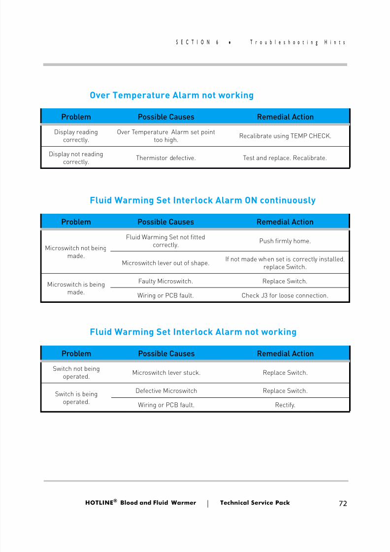
8/13/2019 Smiths Fluid Warmer - General Technical Manual
http://slidepdf.com/reader/full/smiths-fluid-warmer-general-technical-manual 85/131
HOTLINE ® Blood and Fluid Warmer Technical Service Pack 72
S E C T I O N 6 T r o u b l e s h o o t i n g H i n t s
Over Temperature Alarm not working
Fluid Warming Set Interlock Alarm ON continuously
Fluid Warming Set Interlock Alarm not working
Problem Possible Causes Remedial Action
Display readingcorrectly.
Over Temperature Alarm set pointtoo high. Recalibrate using TEMP CHECK.
Display not readingcorrectly. Thermistor defective. Test and replace. Recalibrate.
Problem Possible Causes Remedial Action
Microswitch not beingmade.
Fluid Warming Set not fittedcorrectly. Push firmly home.
Microswitch lever out of shape. If not made when set is correctly installed,replace Switch.
Microswitch is beingmade.
Faulty Microswitch. Replace Switch.
Wiring or PCB fault. Check J3 for loose connection.
Problem Possible Causes Remedial Action
Switch not beingoperated. Microswitch lever stuck. Replace Switch.
Switch is beingoperated.
Defective Microswitch Replace Switch.
Wiring or PCB fault. Rectify.
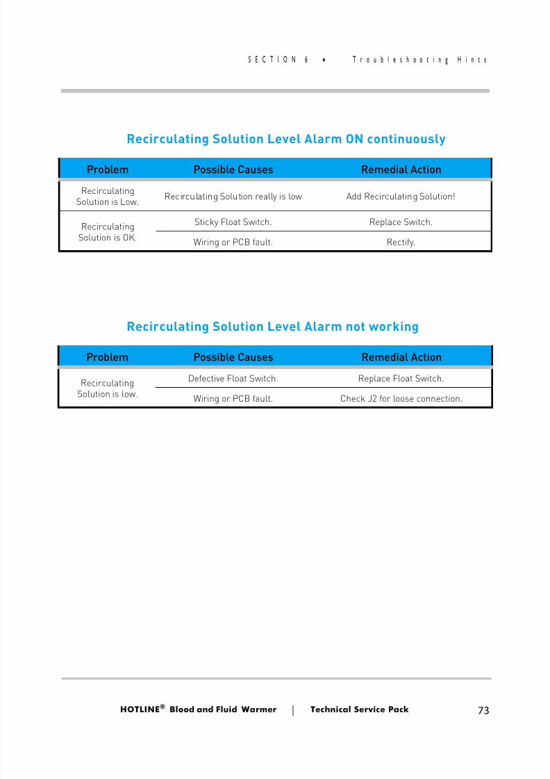
8/13/2019 Smiths Fluid Warmer - General Technical Manual
http://slidepdf.com/reader/full/smiths-fluid-warmer-general-technical-manual 86/131
HOTLINE ® Blood and Fluid Warmer Technical Service Pack 73
S E C T I O N 6 T r o u b l e s h o o t i n g H i n t s
Recirculating Solution Level Alarm ON continuously
Recirculating Solution Level Alarm not working
Problem Possible Causes Remedial Action
RecirculatingSolution is Low. Recirculating Solution really is low Add Recirculating Solution!
RecirculatingSolution is OK.
Sticky Float Switch. Replace Switch.
Wiring or PCB fault. Rectify.
Problem Possible Causes Remedial Action
RecirculatingSolution is low.
Defective Float Switch. Replace Float Switch.
Wiring or PCB fault. Check J2 for loose connection.
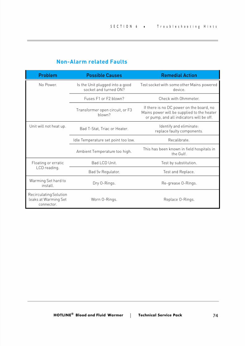
8/13/2019 Smiths Fluid Warmer - General Technical Manual
http://slidepdf.com/reader/full/smiths-fluid-warmer-general-technical-manual 87/131
HOTLINE ® Blood and Fluid Warmer Technical Service Pack 74
S E C T I O N 6 T r o u b l e s h o o t i n g H i n t s
Non-Alarm related Faults
Problem Possible Causes Remedial Action
No Power. Is the Unit plugged into a goodsocket and turned ON?
Test socket with some other Mains powereddevice.
Fuses F1 or F2 blown? Check with Ohmmeter.
Transformer open circuit, or F3blown?
If there is no DC power on the board, noMains power will be supplied to the heater
or pump, and all indicators will be off.
Unit will not heat up. Bad T-Stat, Triac or Heater. Identify and eliminate:replace faulty components.
Idle Temperature set point too low. Recalibrate.
Ambient Temperature too high. This has been known in field hospitals inthe Gulf.
Floating or erraticLCD reading.
Bad LCD Unit. Test by substitution.
Bad 5v Regulator. Test and Replace.
Warming Set hard toinstall. Dry O-Rings. Re-grease O-Rings.
Recirculating Solutionleaks at Warming Set
connector.Worn O-Rings. Replace O-Rings.
8/13/2019 Smiths Fluid Warmer - General Technical Manual
http://slidepdf.com/reader/full/smiths-fluid-warmer-general-technical-manual 88/131
Spare Parts
Blood andFluid Warmer
®
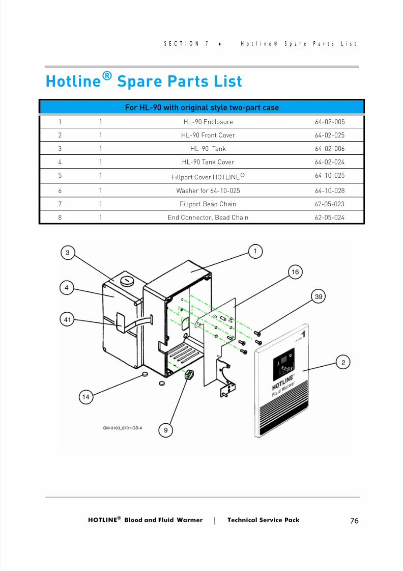
8/13/2019 Smiths Fluid Warmer - General Technical Manual
http://slidepdf.com/reader/full/smiths-fluid-warmer-general-technical-manual 89/131
HOTLINE ® Blood and Fluid Warmer Technical Service Pack 76
S E C T I O N 7 H o t l i n e ® S p a r e P a r t s L i s t
Hotline ® Spare Parts ListFor HL-90 with original style two-part case
1 1 HL-90 Enclosure 64-02-005
2 1 HL-90 Front Cover 64-02-025
3 1 HL-90 Tank 64-02-006
4 1 HL-90 Tank Cover 64-02-024
5 1 Fillport Cover HOTLINE® 64-10-025
6 1 Washer for 64-10-025 64-10-028
7 1 Fillport Bead Chain 62-05-023
8 1 End Connector, Bead Chain 62-05-024
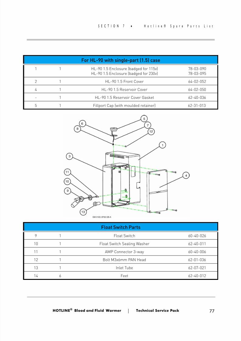
8/13/2019 Smiths Fluid Warmer - General Technical Manual
http://slidepdf.com/reader/full/smiths-fluid-warmer-general-technical-manual 90/131
HOTLINE ® Blood and Fluid Warmer Technical Service Pack 77
S E C T I O N 7 H o t l i n e ® S p a r e P a r t s L i s t
For HL-90 with single-part (1.5) case1 1 HL-90 1.5 Enclosure (badged for 115v)
HL-90 1.5 Enclosure (badged for 230v)78-03-09078-03-095
2 1 HL-90 1.5 Front Cover 64-02-052
4 1 HL-90 1.5 Reservoir Cover 64-02-050
- 1 HL-90 1.5 Reservoir Cover Gasket 62-40-036
5 1 Fillport Cap (with moulded retainer) 62-31-013
Float Switch Parts
9 1 Float Switch 60-40-02610 1 Float Switch Sealing Washer 62-40-011
11 1 AMP Connector 3-way 60-40-006
12 1 Bolt M3x6mm PAN Head 62-01-036
13 1 Inlet Tube 62-07-021
14 6 Feet 62-40-012
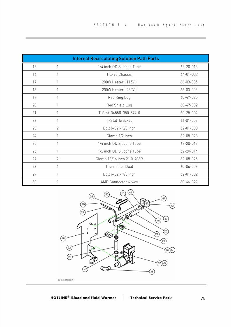
8/13/2019 Smiths Fluid Warmer - General Technical Manual
http://slidepdf.com/reader/full/smiths-fluid-warmer-general-technical-manual 91/131
HOTLINE ® Blood and Fluid Warmer Technical Service Pack 78
S E C T I O N 7 H o t l i n e ® S p a r e P a r t s L i s t
Internal Recirculating Solution Path Parts15 1 1/4 inch OD Silicone Tube 62-20-013
16 1 HL-90 Chassis 64-01-032
17 1 200W Heater ( 115V ) 66-03-005
18 1 200W Heater ( 230V ) 66-03-006
19 1 Red Ring Lug 60-47-025
20 1 Red Shield Lug 60-47-032
21 1 T-Stat 3455R-350-574-0 60-25-00222 1 T-Stat bracket 64-01-052
23 2 Bolt 6-32 x 3/8 inch 62-01-008
24 1 Clamp 1/2 inch 62-05-028
25 1 1/4 inch OD Silicone Tube 62-20-013
26 1 1/2 inch OD Silicone Tube 62-20-014
27 2 Clamp 13/16 inch 21.0-706R 62-05-025
28 1 Thermistor Dual 60-06-003
29 1 Bolt 6-32 x 7/8 inch 62-01-032
30 1 AMP Connector 4-way 60-46-029
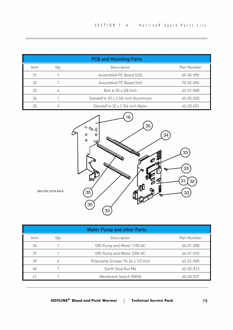
8/13/2019 Smiths Fluid Warmer - General Technical Manual
http://slidepdf.com/reader/full/smiths-fluid-warmer-general-technical-manual 92/131
HOTLINE ® Blood and Fluid Warmer Technical Service Pack 79
S E C T I O N 7 H o t l i n e ® S p a r e P a r t s L i s t
PCB and Mounting PartsItem Qty Description Part Number
31 1 Assembled PC Board (US) 60-60-090
32 1 Assembled PC Board (Int) 70-02-096
33 4 Bolt 6-32 x 3/8 inch 62-01-008
34 1 Standoff 6-32 x 2 3/4 inch Aluminium 62-05-020
35 3 Standoff 6-32 x 2 3/4 inch Nylon 62-05-021
Water Pump and other PartsItem Qty Description Part Number
36 1 GRI Pump and Motor 115V AC 66-01-008
37 1 GRI Pump and Motor 230V AC 66-01-010
39 4 Poleclamp Screws 10-24 x 1/2 inch 62-01-005
40 1 Earth Stud Nut M6 62-02-013
41 1 Membrane Switch (NEK) 60-40-027
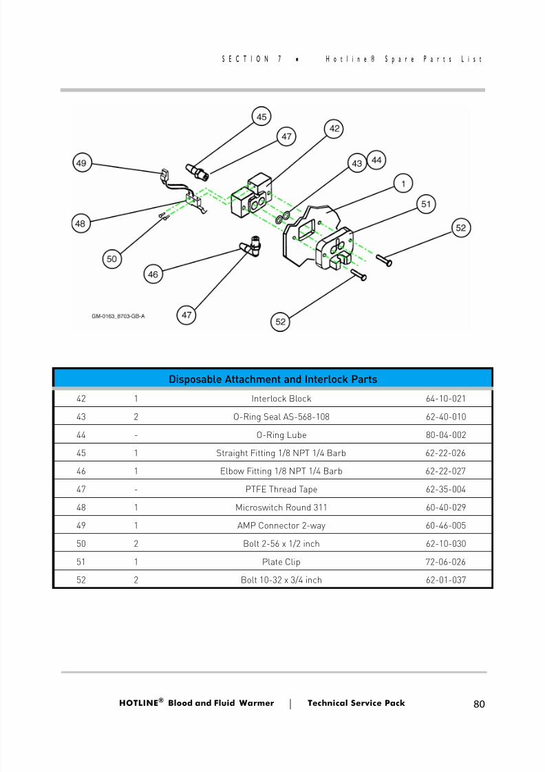
8/13/2019 Smiths Fluid Warmer - General Technical Manual
http://slidepdf.com/reader/full/smiths-fluid-warmer-general-technical-manual 93/131
HOTLINE ® Blood and Fluid Warmer Technical Service Pack 80
S E C T I O N 7 H o t l i n e ® S p a r e P a r t s L i s t
Disposable Attachment and Interlock Parts
42 1 Interlock Block 64-10-021
43 2 O-Ring Seal AS-568-108 62-40-010
44 - O-Ring Lube 80-04-002
45 1 Straight Fitting 1/8 NPT 1/4 Barb 62-22-026
46 1 Elbow Fitting 1/8 NPT 1/4 Barb 62-22-027
47 - PTFE Thread Tape 62-35-004
48 1 Microswitch Round 311 60-40-029
49 1 AMP Connector 2-way 60-46-005
50 2 Bolt 2-56 x 1/2 inch 62-10-030
51 1 Plate Clip 72-06-026
52 2 Bolt 10-32 x 3/4 inch 62-01-037
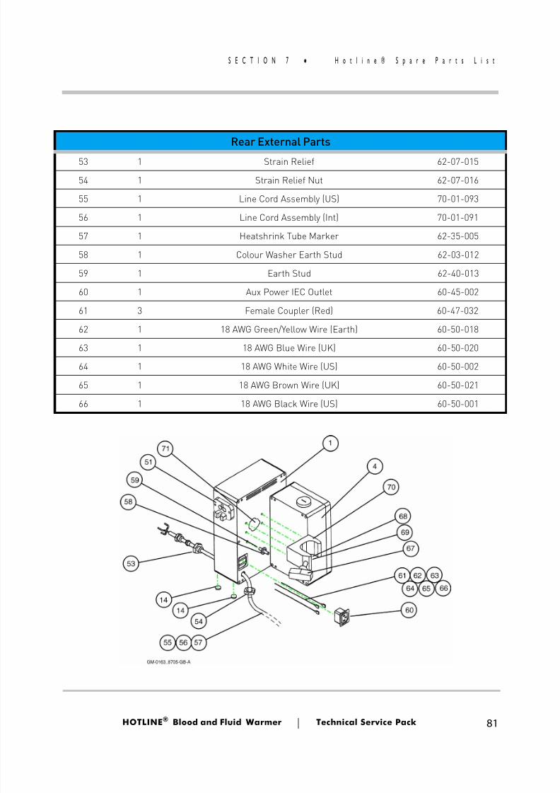
8/13/2019 Smiths Fluid Warmer - General Technical Manual
http://slidepdf.com/reader/full/smiths-fluid-warmer-general-technical-manual 94/131
HOTLINE ® Blood and Fluid Warmer Technical Service Pack 81
S E C T I O N 7 H o t l i n e ® S p a r e P a r t s L i s t
Rear External Parts53 1 Strain Relief 62-07-015
54 1 Strain Relief Nut 62-07-016
55 1 Line Cord Assembly (US) 70-01-093
56 1 Line Cord Assembly (Int) 70-01-091
57 1 Heatshrink Tube Marker 62-35-005
58 1 Colour Washer Earth Stud 62-03-012
59 1 Earth Stud 62-40-01360 1 Aux Power IEC Outlet 60-45-002
61 3 Female Coupler (Red) 60-47-032
62 1 18 AWG Green/Yellow Wire (Earth) 60-50-018
63 1 18 AWG Blue Wire (UK) 60-50-020
64 1 18 AWG White Wire (US) 60-50-002
65 1 18 AWG Brown Wire (UK) 60-50-021
66 1 18 AWG Black Wire (US) 60-50-001
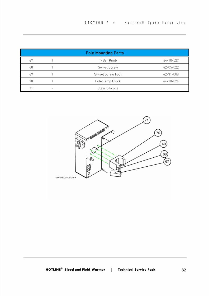
8/13/2019 Smiths Fluid Warmer - General Technical Manual
http://slidepdf.com/reader/full/smiths-fluid-warmer-general-technical-manual 95/131
8/13/2019 Smiths Fluid Warmer - General Technical Manual
http://slidepdf.com/reader/full/smiths-fluid-warmer-general-technical-manual 96/131
Rounding Off
Blood andFluid Warmer
®
8/13/2019 Smiths Fluid Warmer - General Technical Manual
http://slidepdf.com/reader/full/smiths-fluid-warmer-general-technical-manual 97/131
HOTLINE ® Blood and Fluid Warmer Technical Service Pack 84
S E C T I O N 8 R o u n d i n g O f f
Rounding Off This section collects together various loose ends, and in no
particular order attempts to knit them together. Firstly, there’s theupdate history and modification status for the HOTLINE® .
Updates
New Case
Since 2001, the HOTLINE® has been cased in the “1.5” style uni-tary construction combination enclosure and recirculating solutionreservoir. Earlier models had a separate recirculating solution reser-voir bonded onto the rear. The 1.5 style cas ing covers and gasketsare not interchangeable with the original case.
There is no reason to automatically ret ire an old style case atroutine service, unless it has been damaged, or it is desired to per-
form cosmetic upgrading.
Modifications
Two-Second Delay
Current production units, for some time now, have had a two-second delay circuit in the Over Temperature Alarm circuit. This hasalmost no effect on alarms triggered by a change in temperature,
since temperature changes tend to be relatively slow events. How-ever, if the alarm is being triggered by operation of the “Test” but-ton, the original instantaneous action could be too sensitive forcomfort.
This conversion can be applied retrospectively to older HL-90units.
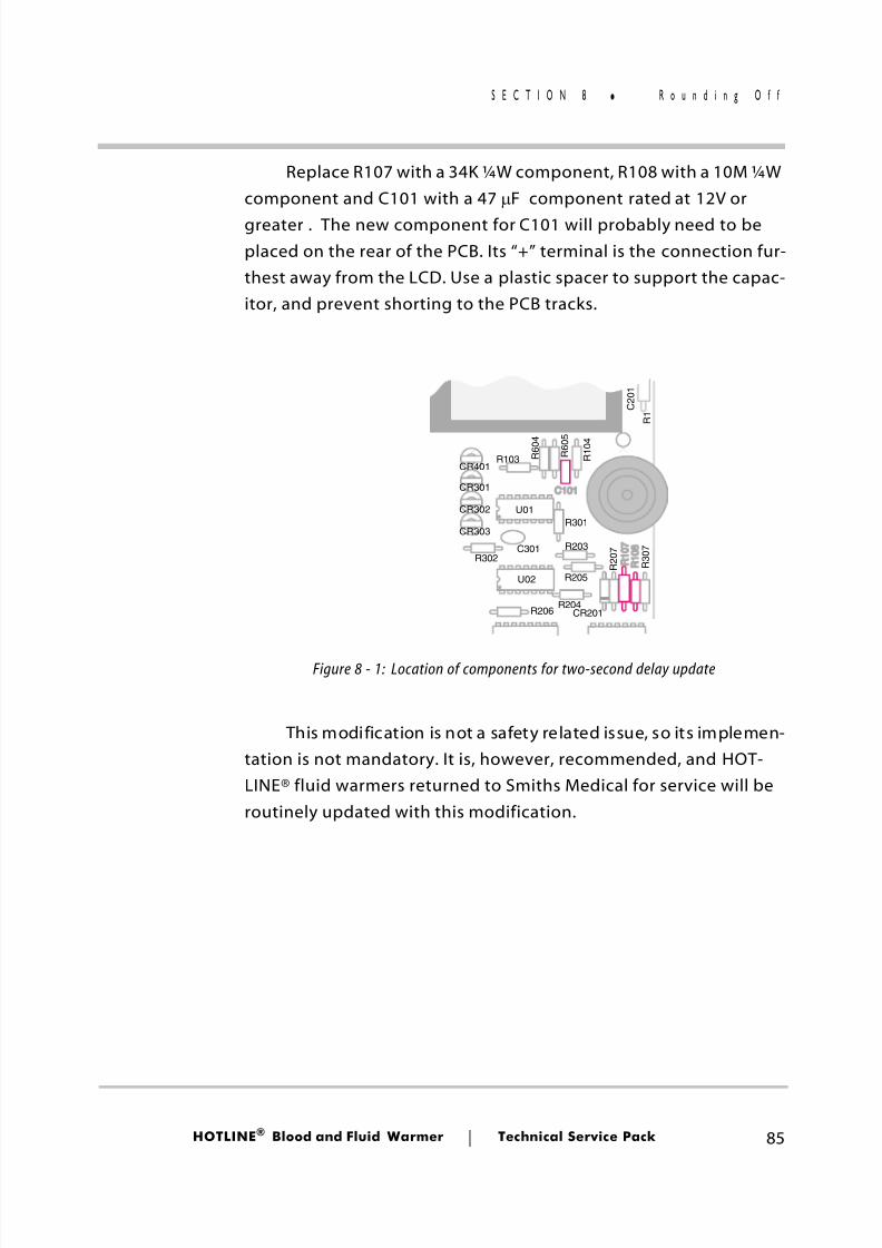
8/13/2019 Smiths Fluid Warmer - General Technical Manual
http://slidepdf.com/reader/full/smiths-fluid-warmer-general-technical-manual 98/131
HOTLINE ® Blood and Fluid Warmer Technical Service Pack 85
S E C T I O N 8 R o u n d i n g O f f
Replace R107 with a 34K ¼W component, R108 with a 10M ¼Wcomponent and C101 with a 47 µ F component rated at 12V orgreater . The new component for C101 will probably need to beplaced on the rear of the PCB. Its “+” terminal is the connection fur-thest away from the LCD. Use a plastic spacer to support the capac-itor, and prevent shorting to the PCB tracks.
This modification is not a safety related issue, so its implemen-tation is not mandatory. It is, however, recommended, and HOT-LINE® fluid warmers returned to Smiths Medical for service will beroutinely updated with this modification.
U01
U02
R206
C 2 0 1
R 1
R103CR401
CR301
R302
CR303
CR302
C301
R301
R203
R205
R204CR201
R 2 0 7
R 3 0 7
R 1 0 4
R 6 0 5
R 6 0 4
Figure 8 - 1: Location of components for two-second delay update
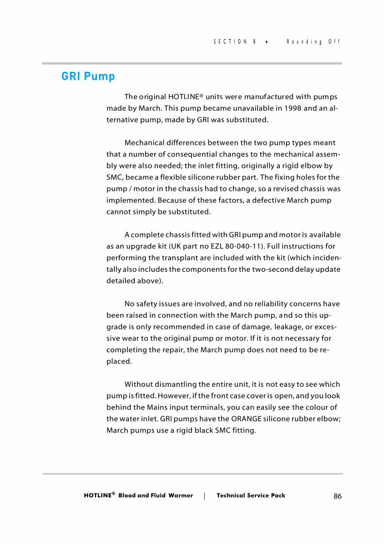
8/13/2019 Smiths Fluid Warmer - General Technical Manual
http://slidepdf.com/reader/full/smiths-fluid-warmer-general-technical-manual 99/131
HOTLINE ® Blood and Fluid Warmer Technical Service Pack 86
S E C T I O N 8 R o u n d i n g O f f
GRI Pump
The original HOTLINE® units were manufactured with pumpsmade by March. This pump became unavailable in 1998 and an al-ternative pump, made by GRI was substituted.
Mechanical differences between the two pump types meantthat a number of consequential changes to the mechanical assem-bly were also needed; the inlet fitting, originally a rigid elbow bySMC, became a flexible silicone rubber part. The fixing holes for the
pump / motor in the chassis had to change, so a revised chassis wasimplemented. Because of these factors, a defective March pumpcannot simply be substituted.
A complete chassis fitted with GRI pump and motor is availableas an upgrade kit (UK part no EZL 80-040-11). Full instructions forperforming the transplant are included with the kit (which inciden-tally also includes the components for the two-second delay update
detailed above).
No safety issues are involved, and no reliability concerns havebeen raised in connection with the March pump, and so this up-grade is only recommended in case of damage, leakage, or exces-sive wear to the original pump or motor. If it is not necessary forcompleting the repair, the March pump does not need to be re-placed.
Without dismantling the entire unit, it is not easy to see whichpump is fitted. However, if the front case cover is open, and you lookbehind the Mains input terminals, you can easily see the colour ofthe water inlet. GRI pumps have the ORANGE silicone rubber elbow;March pumps use a rigid black SMC fitting.
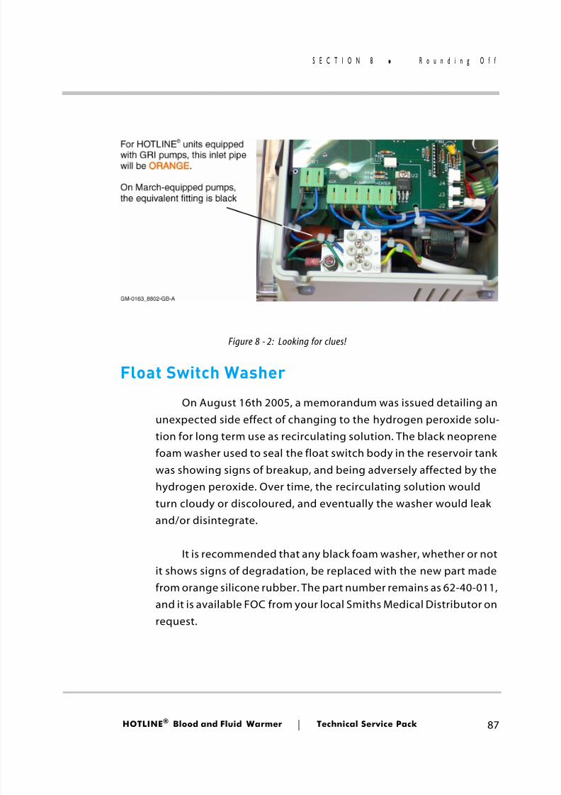
8/13/2019 Smiths Fluid Warmer - General Technical Manual
http://slidepdf.com/reader/full/smiths-fluid-warmer-general-technical-manual 100/131
HOTLINE ® Blood and Fluid Warmer Technical Service Pack 87
S E C T I O N 8 R o u n d i n g O f f
Float Switch Washer
On August 16th 2005, a memorandum was issued detailing an
unexpected side effect of changing to the hydrogen peroxide solu-tion for long term use as recirculating solution. The black neoprenefoam washer used to seal the float switch body in the reservoir tankwas showing signs of breakup, and being adversely affected by thehydrogen peroxide. Over time, the recirculating solution wouldturn cloudy or discoloured, and eventually the washer would leakand/or disintegrate.
It is recommended that any black foam washer, whether or notit shows signs of degradation, be replaced with the new part madefrom orange silicone rubber. The part number remains as 62-40-011,and it is available FOC from your local Smiths Medical Distributor onrequest.
Figure 8 - 2: Looking for clues!
8/13/2019 Smiths Fluid Warmer - General Technical Manual
http://slidepdf.com/reader/full/smiths-fluid-warmer-general-technical-manual 101/131
HOTLINE ® Blood and Fluid Warmer Technical Service Pack 88
S E C T I O N 8 R o u n d i n g O f f
HOTLINE® Quiz
[1] What is the maximum height above floor level allowed for aHOTLINE® on an IV pole?
[2] The HOTLINE® is connected to a viable Mains source, but noLEDS are ON, and the pump is not running. Some of these com-ponents can be instantly ruled out and others are valid sus-pects. Put “X”s against those components that you think couldnot possibly be the problem.
[3] Which of these is the symbol for the Recirculating SolutionLOW Level Alarm?
40 inches 42 inches
44 inches 46 inches
Regulator U501 Relay K1
Transformer T1 Triac U2
Control Thermistor Display Thermistor
8/13/2019 Smiths Fluid Warmer - General Technical Manual
http://slidepdf.com/reader/full/smiths-fluid-warmer-general-technical-manual 102/131
HOTLINE ® Blood and Fluid Warmer Technical Service Pack 89
S E C T I O N 8 R o u n d i n g O f f
[4] What is the function of the control identified by this symbol?
[5] Which of these is not required by the 30-day routine mainte-nance?
[6] Which of these is an acceptable formula for a solution suitable
for long-term use in the system as a recirculating solution?
Switch on Heater Switch on Pump
Test All Alarms Clear Airlock
General Alarm Test Low Water Alarm Test
Over Temperature Alarm Test Re-grease O-Rings
140 mL 3% Hydrogen Peroxide + 1180 mL Distilled water
140 mL 3% Hydrogen Peroxide + 1260 mL Distilled water
140 mL 3% Hydrogen Peroxide + 1320 mL Distilled water
140 mL 3% Hydrogen Peroxide + 1400 mL Distilled water
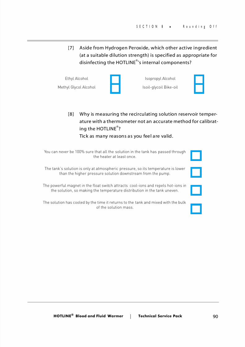
8/13/2019 Smiths Fluid Warmer - General Technical Manual
http://slidepdf.com/reader/full/smiths-fluid-warmer-general-technical-manual 103/131
HOTLINE ® Blood and Fluid Warmer Technical Service Pack 90
S E C T I O N 8 R o u n d i n g O f f
[7] Aside from Hydrogen Peroxide, which other active ingredient(at a suitable dilution strength) is specified as appropriate fordisinfecting the HOTLINE ®’s internal components?
[8] Why is measuring the recirculating solution reservoir temper-
ature with a thermometer not an accurate method for calibrat-ing the HOTLINE ®? Tick as many reasons as you feel are valid.
Ethyl Alcohol Isopropyl Alcohol
Methyl Glycol Alcohol Isoil-glycoil Bike-oil
You can never be 100% sure that all the solution in the tank has passed throughthe heater at least once.
The tank’s solution is only at atmospheric pressure, so its temperature is lowerthan the higher pressure solution downstream from the pump.
The powerful magnet in the float switch attracts cool-ions and repels hot-ions inthe solution, so making the temperature distribution in the tank uneven.
The solution has cooled by the time it returns to the tank and mixed with the bulkof the solution mass.
8/13/2019 Smiths Fluid Warmer - General Technical Manual
http://slidepdf.com/reader/full/smiths-fluid-warmer-general-technical-manual 104/131
Title of Training Program
Program Presenter
LocationTrainee (optional)
Date
General
Other (what?)
S.M.I. Ltd Rep
Magazine advert
1) How did you (or your boss) find out about this course?
Colleague (this establishment)
Colleague (another establishment)
What was your opinion of the facilities where this course was held?
Course Conditions
Was the course content relevant to you in your job?
Was the level of the course content appropriate?
Was the quantity of information in this course sufficient for this topic?
Course Content
4) Would you recommend this course to others in your position? Yes / No
3) What objectives did it fail to meet?
2) How well did the course meet your training objectives?
Not good Very good
Not at all Exactly right
Too basic Too advanced
Not enough Too much
Not at all Completely
8/13/2019 Smiths Fluid Warmer - General Technical Manual
http://slidepdf.com/reader/full/smiths-fluid-warmer-general-technical-manual 105/131
9) What was your opinion of the instructional materials provided with this course?
13) What suggestions would you make regarding future courses?
Feedback, please!
Course Presentation
12) What improvements would you suggest for this course?
... and (b) effectiveness at communicating)
(marks for (a) knowledge ...
11) What was your opinion of the course presenter?
10) What was your opinion of the A-V or multimedia aids (if any) used in this course?
(marks for (a) quality ...
(marks for (a) quality ...
... and (b) appropriateness)
... and (b) appropriateness)
Thank you for taking the time to complete this evaluation!
Not good Very good
Not good Very good
Not good Very good
Not good Very good
Not good Very good
Not good Very good
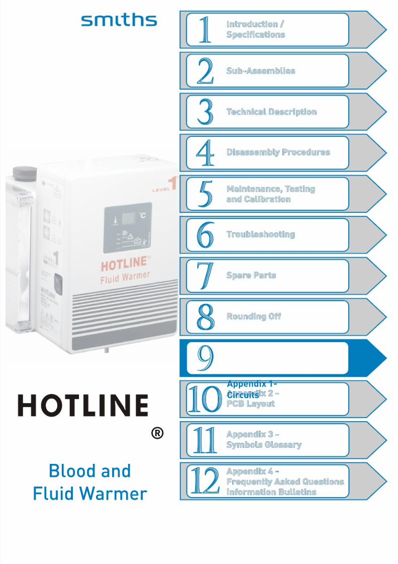
8/13/2019 Smiths Fluid Warmer - General Technical Manual
http://slidepdf.com/reader/full/smiths-fluid-warmer-general-technical-manual 106/131
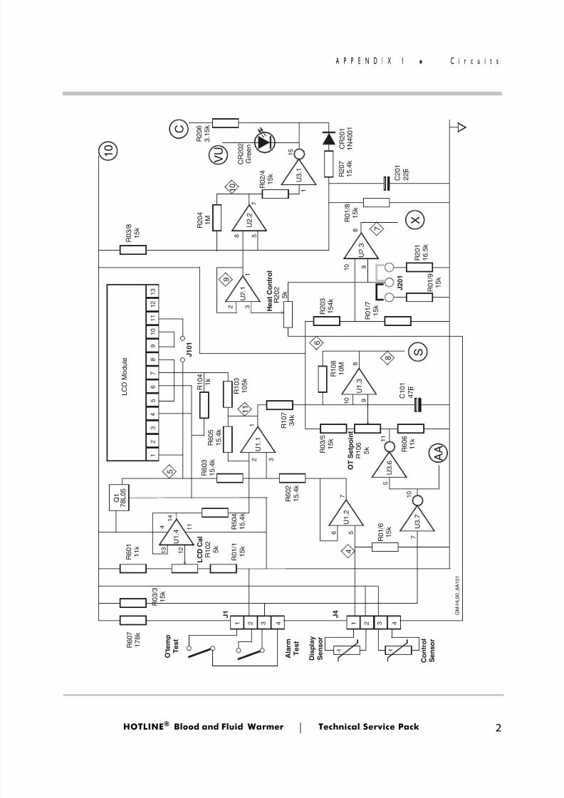
8/13/2019 Smiths Fluid Warmer - General Technical Manual
http://slidepdf.com/reader/full/smiths-fluid-warmer-general-technical-manual 107/131
HOTLINE ® Blood and Fluid Warmer Technical Service Pack 2
A P P E N D I X 1 C i r c u i t s
G M - H
L 9 0_ 8 A 1 0 1
Q 1
7 8 L 0 5
L C D M o d u l e
A l a r m
T e s
t
O ' t e m p
T e s
t
C o n
t r o l
S e n s o r
D i s p
l a y
S e n s o r
U 1 . 4
U 1 . 1
U 1 . 2
J 4
J 1
U 3 . 1
U 2 . 2
U 2 . 3
J 2 0 1
U 3 . 7
1 0
1
2
3
4
5
6
7
8
9
1 0
1 1
1 2 1 3
- t - t
1 1 2 2 3 3 4 4
U 3 . 6
V U
C
S
A A
X
5
8
4
1 1
9
6
1 0
7
R 2 0 2
5 k
H e a
t C o n t r o
l
R 2 0 3
1 5 4 k
R 1 0 8
1 0 M
R 0 3 / 5
1 5 k
O T S e
t p o
i n t
R 1 0 6
5 k
L C D C a
l
R 1 0 2
5 k
R 1 0 7
3 4 k
R 5 0 4
1 5 . 4 k
R 6 0 3
1 5 . 4 k
R 6 0 7
1 7 8 k
R 6 0 1
1 1 k
R 0 3 / 3
1 5 k
R 0 1 / 1
1 5 k
R 6 0 2
1 5 . 4 k
R 0 1 / 6
1 5 k
R 6 0 5
1 5 . 4 k
R 1 0 3
1 0 5 k R 1 0 4
1 k
J 1 0 1
R 6 0 6
1 1 k
R 0 1 / 7
1 5 k
R 2 0 4
1 M
R 0 2 / 4
1 5 k
R 0 3 / 8
1 5 k R 0 1 / 8
1 5 k
R 0 1 / 9
1 5 k
R 2 0 1
1 6 . 5 k
R 2 0 6
3 . 1 5 k
R 2 0 7
1 5 . 4 k
C R 2 0 1
1 N 4 0 0 1
C 2 0 1
2 2 F µ
C 1 0 1
4 7 F µ U 1 . 3
1 2
1 1 4
1 3
1 4
5
9
9
3
5
1
6
1 1
1 0
1 0
1 0
2
6
7
5
7
8
8
1
7
1 5
2 3
1
U 2 . 1
C R 2 0 2
G r e e n
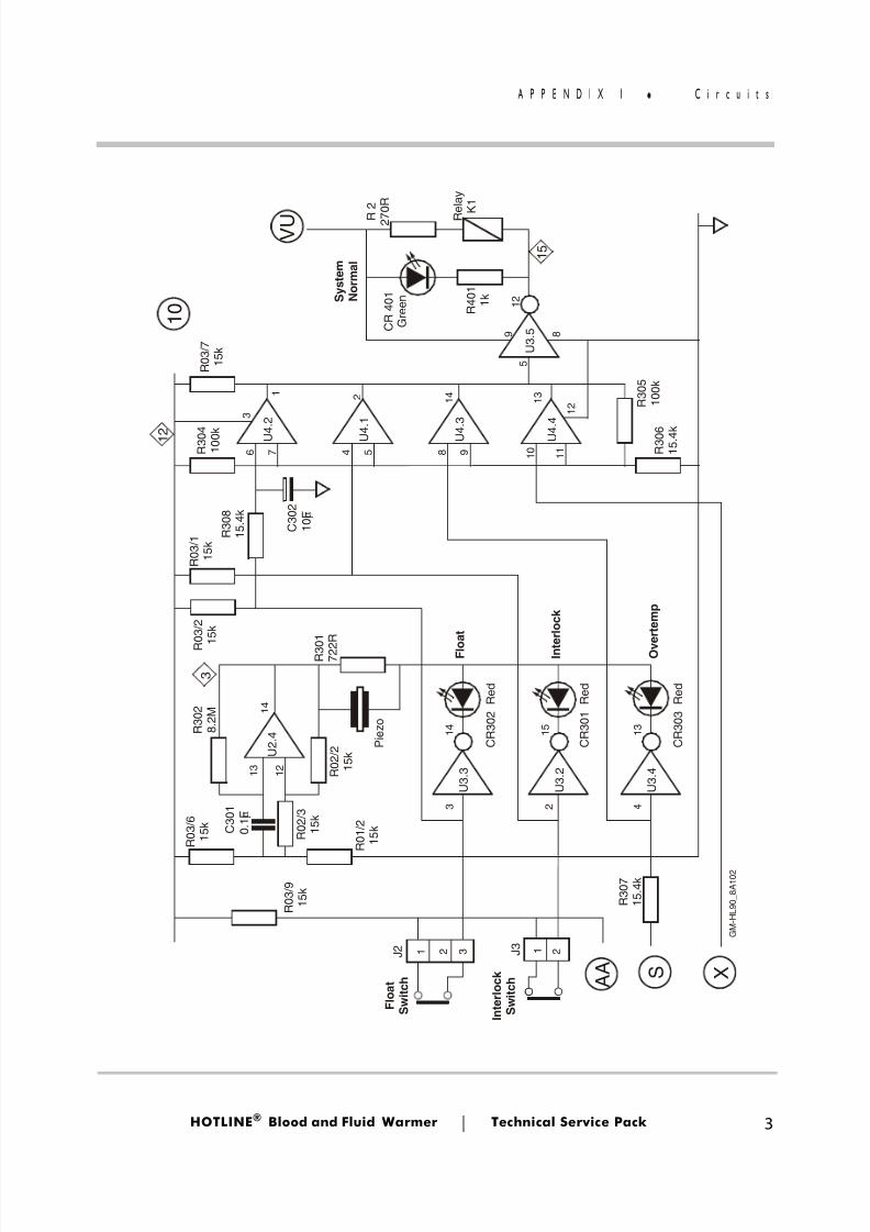
8/13/2019 Smiths Fluid Warmer - General Technical Manual
http://slidepdf.com/reader/full/smiths-fluid-warmer-general-technical-manual 108/131
HOTLINE ® Blood and Fluid Warmer Technical Service Pack 3
A P P E N D I X 1 C i r c u i t s
F l o a t
S w i t c h
F l o a t
S y s t e m
N o r m a l
I n t e r l o c k
S w i t c h
I n t e r l o c k
O v e r t e m p
J 3
J 2
U 4 . 2
U 4 . 1
U 4 . 3
U 4 . 4
R e
l a y
K 1
U 3
. 3
P i e z o
U 3
. 2
U 3
. 4
U 3
. 5
U 2
. 4
S X A A
1 0
V U
1 5
1 2
3
R 3 0 5
1 0 0 k
R 0 3 / 7
1 5 k
R 0 3 / 1
1 5 k
R 0 3 / 2
1 5 k
R 3 0 2
8 . 2
M
R 3 0 7
1 5
. 4 k
R 3 0 1
7 2 2 R
R 0 2 / 2
1 5 k
R 0 2 / 3
1 5 k
R 0 1 / 2
1 5 k
R 0 3 / 6
1 5 k
R 0 3 / 9
1 5 k
R 3 0 4
1 0 0 k
R 3 0 8
1 5
. 4 k
R 3 0 6
1 5
. 4 k
C R 3 0 2 R e
d
C R 3 0 1 R e
d
C R 3 0 3 R e
d
R 2
2 7 0 R
C R 4 0 1
G r e e n
R 4 0 1
1 k
C 3 0 2
1 0 F µ
C 3 0 1
0 . 1
F µ
3
2
1 4
4
1 3
6 5
1 2
7 1 0
1 1
1 2 1
3
5
9 8
1 2
3
3 1 1 2 2
2 4
1 5
1 4
1 3
8
1 4
9
1
G M - H
L 9 0
_ 8 A 1 0 2
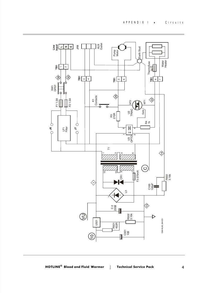
8/13/2019 Smiths Fluid Warmer - General Technical Manual
http://slidepdf.com/reader/full/smiths-fluid-warmer-general-technical-manual 109/131
8/13/2019 Smiths Fluid Warmer - General Technical Manual
http://slidepdf.com/reader/full/smiths-fluid-warmer-general-technical-manual 110/131
Appendix 2 -PCB Layout
Blood andFluid Warmer
®
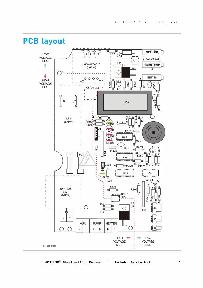
8/13/2019 Smiths Fluid Warmer - General Technical Manual
http://slidepdf.com/reader/full/smiths-fluid-warmer-general-technical-manual 111/131
HOTLINE ® Blood and Fluid Warmer Technical Service Pack 2
A P P E N D I X 2 P C B l a y o u t
PCB layout
Transformer T1(below)
791012
14
57 68F3 CR1
U1R2
C2(below)
U501
K1 (below)
U102
J1
U01
U02
U03
R 0 2
R 0 1
CR202R201
J201 R206
OPTOU3
R208
R3
R4 TRIACU2
SWITCHSW1
(below)
F1 F2
LF1(below)
J6 J7
J4
J3
J2
LOWVOLTAGE
SIDE
LOWVOLTAGE
SIDE
HIGHVOLTAGE
SIDE
HIGHVOLTAGE
SIDE R 6 0 2
R 6 0 3
Q1 R 5 0 1
R 5 0 2
C 5 0 1
C 2 0 1
C 1
R 1
R401
R607R606
R103
R302C301
R301
R203
R205
R204CR201
R 2 0 7
R 1 0 7
R 1 0 8
C302
R306
R03
R 3 0 7
U04
R 3 0 5
R 3 0 4
R 1 0 4
C101 (below)
R 6 0 5
R 6 0 4
+
+
++
+
+
GM-HL90_8A201
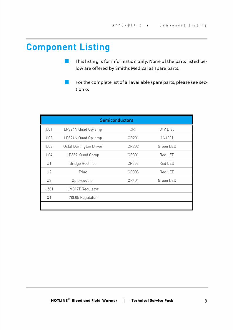
8/13/2019 Smiths Fluid Warmer - General Technical Manual
http://slidepdf.com/reader/full/smiths-fluid-warmer-general-technical-manual 112/131
HOTLINE ® Blood and Fluid Warmer Technical Service Pack 3
A P P E N D I X 2 C o m p o n e n t L i s t i n g
Component Listing■ This l isting is for information only. None of the parts listed be-
low are offered by Smiths Medical as spare parts.
■ For the complete list of all available spare parts, please see sec-tion 6.
Semiconductors
U01 LP324N Quad Op-amp CR1 34V Diac
U02 LP324N Quad Op-amp CR201 1N4001
U03 Octal Darlington Driver CR202 Green LED
U04 LP339 Quad Comp CR301 Red LED
U1 Bridge Rectifier CR302 Red LED
U2 Triac CR303 Red LEDU3 Opto-coupler CR401 Green LED
U501 LM317T Regulator
Q1 78L05 Regulator
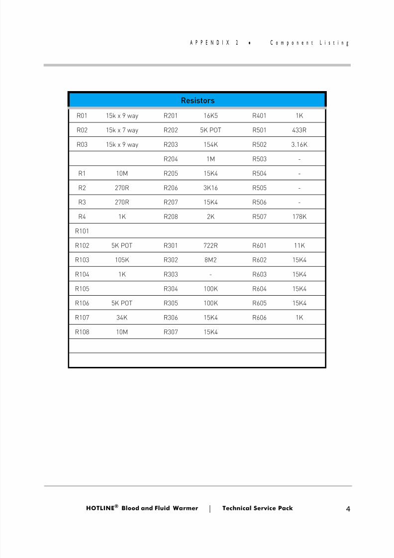
8/13/2019 Smiths Fluid Warmer - General Technical Manual
http://slidepdf.com/reader/full/smiths-fluid-warmer-general-technical-manual 113/131
HOTLINE ® Blood and Fluid Warmer Technical Service Pack 4
A P P E N D I X 2 C o m p o n e n t L i s t i n g
Resistors
R01 15k x 9 way R201 16K5 R401 1K
R02 15k x 7 way R202 5K POT R501 433R
R03 15k x 9 way R203 154K R502 3.16K
R204 1M R503 -
R1 10M R205 15K4 R504 -
R2 270R R206 3K16 R505 -
R3 270R R207 15K4 R506 -
R4 1K R208 2K R507 178K
R101
R102 5K POT R301 722R R601 11K
R103 105K R302 8M2 R602 15K4
R104 1K R303 - R603 15K4
R105 R304 100K R604 15K4R106 5K POT R305 100K R605 15K4
R107 34K R306 15K4 R606 1K
R108 10M R307 15K4
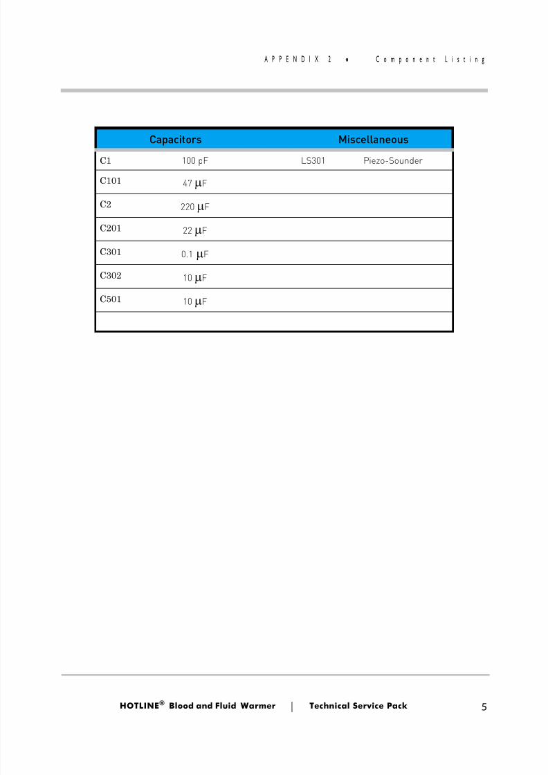
8/13/2019 Smiths Fluid Warmer - General Technical Manual
http://slidepdf.com/reader/full/smiths-fluid-warmer-general-technical-manual 114/131
HOTLINE ® Blood and Fluid Warmer Technical Service Pack 5
A P P E N D I X 2 C o m p o n e n t L i s t i n g
Capacitors Miscellaneous
C1 100 pF LS301 Piezo-Sounder
C101 47 µ F
C2 220 µ F
C201 22 µ F
C301 0.1 µ F
C302 10 µ F
C501 10 µ F
8/13/2019 Smiths Fluid Warmer - General Technical Manual
http://slidepdf.com/reader/full/smiths-fluid-warmer-general-technical-manual 115/131
Appendix 3 -Symbols Glossary
Blood andFluid Warmer
®
8/13/2019 Smiths Fluid Warmer - General Technical Manual
http://slidepdf.com/reader/full/smiths-fluid-warmer-general-technical-manual 116/131
HOTLINE ® Blood and Fluid Warmer Technical Service Pack 2
A P P E N D I X 3 S y m b o l s G l o s s a r y
Symbols GlossarySymbol Meaning
Read Instructions before useor (failing that)
Disposable Interlock Alarm. The Warming Set is not connected correctly,and must be reattached before proceeding.
Degrees Celsius
Recirculating solution temperature
Operating normally.Recirculating solution is being warmed and circulated
Recirculating solution Level Alarm.To clear alarm you must add recirculating solution to the reservoir.
Over Temperature Alarm.Unit must be serviced by a trained technician prior to reuse.
General Alarm Test Button that simulates the Over Temperature, LowRecirculating Solution and Interlock Alarm conditions. The alarm lamps
should all flash, and the audible alarm should sound repetitively.
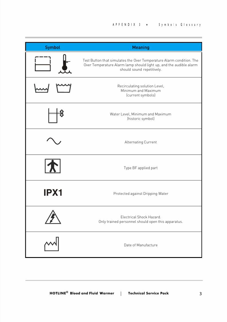
8/13/2019 Smiths Fluid Warmer - General Technical Manual
http://slidepdf.com/reader/full/smiths-fluid-warmer-general-technical-manual 117/131
HOTLINE ® Blood and Fluid Warmer Technical Service Pack 3
A P P E N D I X 3 S y m b o l s G l o s s a r y
Test Button that simulates the Over Temperature Alarm condition. TheOver Temperature Alarm lamp should light up, and the audible alarm
should sound repetitively.
Recirculating solution Level,Minimum and Maximum
(current symbols)
Water Level, Minimum and Maximum(historic symbol)
Alternating Current
Type BF applied part
Protected against Dripping Water
Electrical Shock Hazard.Only trained personnel should open this apparatus.
Date of Manufacture
Symbol Meaning
8/13/2019 Smiths Fluid Warmer - General Technical Manual
http://slidepdf.com/reader/full/smiths-fluid-warmer-general-technical-manual 118/131
Appendix 4 -Frequently Asked QuestionsInformation Bulletins
Blood andFluid Warmer
®
8/13/2019 Smiths Fluid Warmer - General Technical Manual
http://slidepdf.com/reader/full/smiths-fluid-warmer-general-technical-manual 119/131
HOTLINE ® Blood and Fluid Warmer Technical Service Pack 2
A P P E N D I X 4 F r e q u e n t l y A s k e d Q u e s t i o n
Frequently Asked Questions These are general Questions and their Answers about various
aspects of HOTLINE ® operation that, while not technical, others inyour establishment may well think you should be able to give themthe answer!
■ What is the temperature of the intravenous fluid and bloodthat is delivered to the patient?
■ Usually about 41 º C. With the patented HOTLINE ® tubingdesign, the tubing - the intravenous pathway surrounded bythe recirculating solution - is the heat exchanger for thesystem. The intravenous line is jacketed by the recirculatingsolution, warming the infusate fluid or blood all the way tothe patient. Because heat is exchanged all along the patient
line, the infusate temperature is dependent on the flow ratethat you set for the intravenous infusion.
■ Other warming systems typically warm fluid and bloodbetween warming plates inside the machine. As the warmedfluid or blood flows through the tubing toward the patient itloses most of the amassed heat to the ambient air - which istermed "patient line cool-down."
■ Am I overheating intravenous solutions and blood by warmingat 42 ºC?
■ Effective 1997, the American Association of Blood Bankschanged its blood warming temperature threshold. Section J8.200 of the 19th Edition of the AABB's Standards for BloodBanks and Transfusion Services states, "When blood is
8/13/2019 Smiths Fluid Warmer - General Technical Manual
http://slidepdf.com/reader/full/smiths-fluid-warmer-general-technical-manual 120/131
HOTLINE ® Blood and Fluid Warmer Technical Service Pack 3
A P P E N D I X 4 F r e q u e n t l y A s k e d Q u e s t i o n
warmed, it must be done so as not to cause hemolysis." Inthe abstract, "The Effect of Heat on In-Vitro Parameters ofRed Cell Integrity", presented at the 46th Annual Meeting ofthe AABB, Uhl, Pacini and Kruskall state that "subtlealterations in red cell integrity are not apparent until 46 º Cand frank hemolysis not until 48 º C."
■ All Level 1® Fluid Warming Systems' heat exchanger set point temperatures are established in accordance with thisstandard. The primary temperature control circuit limits the
recirculating solution temperature to 42 º C. The fluid in theHOTLINE ® disposable tubing remains well within theacceptable range. Because the recirculating solutionautomatically shuts down in the unlikely event of an overtemperature situation, the blood or intravenous fluid in theHOTLINE® Warming Set would also remain in theacceptable range.
■Some patients and clinicians are sensitive to latex. Do Level 1®products, specifically the disposable tubing sets, contain anylatex?
■ Level 1® fluid warming machines have no external latex parts, and apart from the L-10 Gas Vent, no HOTLINE ® disposables or accessories contain latex.
■ Listed in the Level 1 ® Latex Letter are the disposable products that are currently "latex-free," and if applicable, atransition lot number for when they became latex-free isindicated in parenthesis. Also listed are the disposable products that do contain latex.
8/13/2019 Smiths Fluid Warmer - General Technical Manual
http://slidepdf.com/reader/full/smiths-fluid-warmer-general-technical-manual 121/131
HOTLINE ® Blood and Fluid Warmer Technical Service Pack 4
A P P E N D I X 4 F r e q u e n t l y A s k e d Q u e s t i o n
■ What is the maintenance requirement on my Level 1®HOTLINE® fluid warmer?
■ If you operate your HOTLINE® with distilled water as therecirculating solution, the following maintenance will beneeded:
■ Monthly:Lubricate the O-Rings with silicone lubricantChange the distilled water
Disinfect the recirculating solution path
■ Annually:O-Rings should be changed Test the fault condition alarmsVerify the temperature calibration
■ If you operate your HOTLINE® with an approved
microbicidal solution as the recirculating solution (asrecommended by Smiths Medical), the followingmaintenance will be needed:
■ Monthly:Lubricate the O-Rings with silicone lubricant
■ Annually:Change the recirculating solutionO-Rings should be changed Test the fault condition alarmsVerify the temperature calibration
■ Complete maintenance procedures are provided in allOperator's & Service Manuals.
8/13/2019 Smiths Fluid Warmer - General Technical Manual
http://slidepdf.com/reader/full/smiths-fluid-warmer-general-technical-manual 122/131
HOTLINE ® Blood and Fluid Warmer Technical Service Pack 5
A P P E N D I X 4 F r e q u e n t l y A s k e d Q u e s t i o n
■ Is my disposable sterile?
■ All Level 1® IV disposables are labeled with "sterile fluid paths" only. Level 1 ® IV disposables should not be passedinto a sterile field. Level 1 ® irrigating disposables, however,do include a sterile patient line, which can be passed into asterile field.
■ How can I be sure that the recirculating solution won't mix
with the IV fluid in my L-70 disposable?
■ The L-70 triple lumen tubing is a single extrusion tube andthe connectors are solvent bonded to the tubing. The plastics actually fuse together, so neither the tubing nor theconnectors can "come apart" or become "unglued." It isimportant to follow the Instructions for Use to ensure theintegrity of the tubing is confirmed every time an L-70 is set
up. Important steps to remember are:
[i] Priming the recirculating solution path before connectingto the intravenous administration set.
[ii] Inspecting the patient end of the tubing for leaks will con-firm integrity of the line.
[iii] Do not kink the warming set tubing.
[iv] Do not restrict solution circulation through the tubing.
8/13/2019 Smiths Fluid Warmer - General Technical Manual
http://slidepdf.com/reader/full/smiths-fluid-warmer-general-technical-manual 123/131
HOTLINE ® Blood and Fluid Warmer Technical Service Pack 6
A P P E N D I X 4 G e n e r a l A d v i s e m e n t
General Advisement These Customer Information Bullet ins are included for histori-
cal completeness. They relate to subjects that were significant at thetime of issue . Please be aware that the information contained inthem may have been superseded by later-issue bulletins or work-sheets, or by information published in the Technical Service Pack.Due to continuous evaluation and improvements, changes in spec-ification may also have rendered information in these sheets obso-lete.
Both Customer Information Bulletins and Technical Work-sheets are issued on an irregular basis to address specific topics asthey arise. Therefore, these lists are likely to be incomplete and outof date within a fairly short time. If your department does not cur-rently receive updates, you can ensure that you keep your collec-tion complete and maximise its usefulness, by contacting (in theU.S.) your local distributor, or (in the U.K. and Europe) the QA de-
partment at the Watford (U.K.) offices of Smiths Medical Internation-al ( +44 (0)1923 246434), who will arrange for you to receive futurereleases either by email or post.
At the present time, there are only three bulletins and a Webannouncement referring specifically to HOTLINE ®-related matters.All but one of these detail the reduction in frequency of the refresh-ment cycle for the recirculating solution from 30 days to annually.
The remaining bulletin highlights a consequence of the continualexposure of the fluid path to the potentially corrosive peroxide,and explains the remedy.
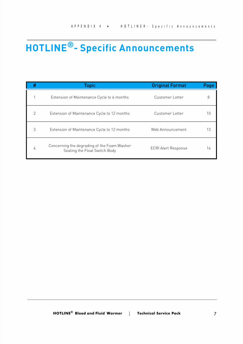
8/13/2019 Smiths Fluid Warmer - General Technical Manual
http://slidepdf.com/reader/full/smiths-fluid-warmer-general-technical-manual 124/131
HOTLINE ® Blood and Fluid Warmer Technical Service Pack 7
A P P E N D I X 4 H O T L I N E ® - S p e c i f i c A n n o u n c e m
# Topic Original Format Page
1 Extension of Maintenance Cycle to 6 months Customer Letter 8
2 Extension of Maintenance Cycle to 12 months Customer Letter 10
3 Extension of Maintenance Cycle to 12 months Web Announcement 13
4 Concerning the degrading of the Foam WasherSealing the Float Switch Body ECRI Alert Response 14
HOTLINE®- Specific Announcements
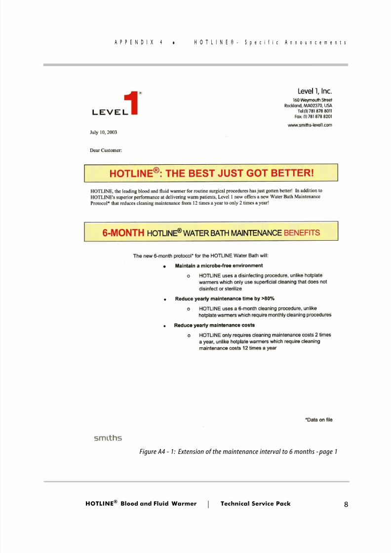
8/13/2019 Smiths Fluid Warmer - General Technical Manual
http://slidepdf.com/reader/full/smiths-fluid-warmer-general-technical-manual 125/131
HOTLINE ® Blood and Fluid Warmer Technical Service Pack 8
A P P E N D I X 4 H O T L I N E ® - S p e c i f i c A n n o u n c e m
Figure A4 - 1: Extension of the maintenance interval to 6 months - page 1
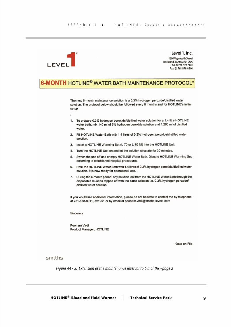
8/13/2019 Smiths Fluid Warmer - General Technical Manual
http://slidepdf.com/reader/full/smiths-fluid-warmer-general-technical-manual 126/131
HOTLINE ® Blood and Fluid Warmer Technical Service Pack 9
A P P E N D I X 4 H O T L I N E ® - S p e c i f i c A n n o u n c e m
Figure A4 - 2: Extension of the maintenance interval to 6 months - page 2
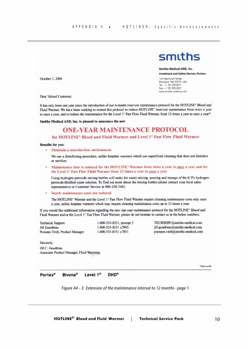
8/13/2019 Smiths Fluid Warmer - General Technical Manual
http://slidepdf.com/reader/full/smiths-fluid-warmer-general-technical-manual 127/131
HOTLINE ® Blood and Fluid Warmer Technical Service Pack 10
A P P E N D I X 4 H O T L I N E ® - S p e c i f i c A n n o u n c e m
Figure A4 - 3: Extension of the maintenance interval to 12 months - page 1
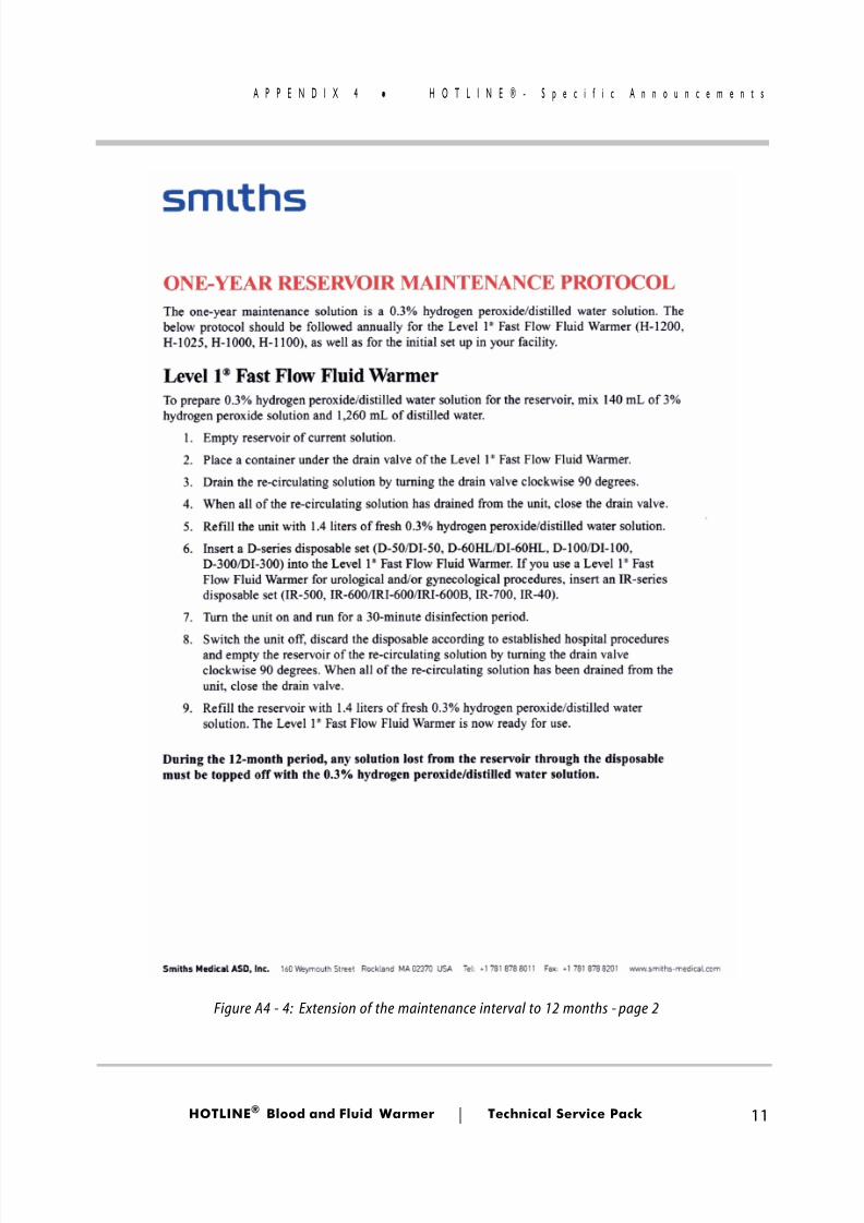
8/13/2019 Smiths Fluid Warmer - General Technical Manual
http://slidepdf.com/reader/full/smiths-fluid-warmer-general-technical-manual 128/131
HOTLINE ® Blood and Fluid Warmer Technical Service Pack 11
A P P E N D I X 4 H O T L I N E ® - S p e c i f i c A n n o u n c e m
Figure A4 - 4: Extension of the maintenance interval to 12 months - page 2
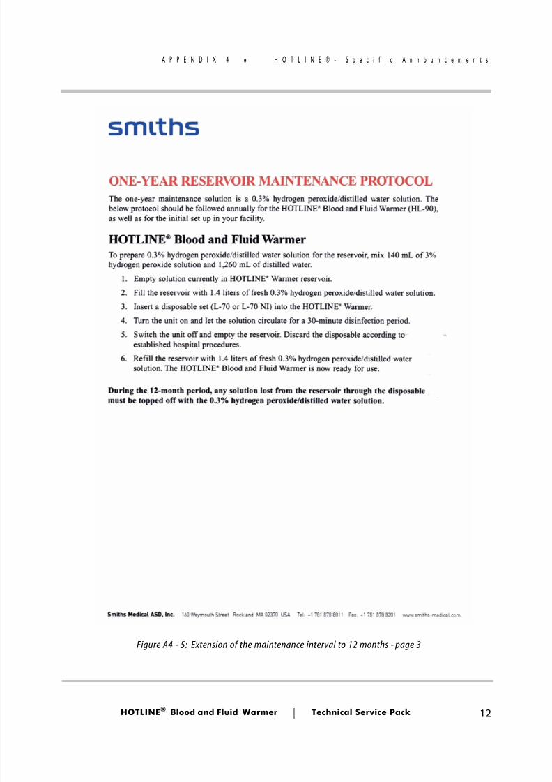
8/13/2019 Smiths Fluid Warmer - General Technical Manual
http://slidepdf.com/reader/full/smiths-fluid-warmer-general-technical-manual 129/131
HOTLINE ® Blood and Fluid Warmer Technical Service Pack 12
A P P E N D I X 4 H O T L I N E ® - S p e c i f i c A n n o u n c e m
Figure A4 - 5: Extension of the maintenance interval to 12 months - page 3
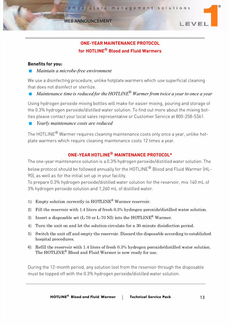
8/13/2019 Smiths Fluid Warmer - General Technical Manual
http://slidepdf.com/reader/full/smiths-fluid-warmer-general-technical-manual 130/131
HOTLINE ® Blood and Fluid Warmer Technical Service Pack 13
A P P E N D I X 4 H O T L I N E ® - S p e c i f i c A n n o u n c e m
ONE-YEAR MAINTENANCE PROTOCOL
for HOTLINE® Blood and Fluid Warmers
Benefits for you:■ Maintain a microbe-free environment
We use a disinfecting procedure, unlike hotplate warmers which use superficial cleaningthat does not disinfect or sterilize.■ Maintenance time is reduced for the HOTLINE ® Warmer from twice a year to once a year
Using hydrogen peroxide mixing bottles will make for easier mixing, pouring and storage ofthe 0.3% hydrogen peroxide/distilled water solution. To find out more about the mixing bot-tles please contact your local sales representative or Customer Service at 800-258-5361.■ Yearly maintenance costs are reduced
The HOTLINE® Warmer requires cleaning maintenance costs only once a year, unlike hot-plate warmers which require cleaning maintenance costs 12 times a year.
ONE-YEAR HOTLINE® MAINTENANCE PROTOCOL*The one-year maintenance solution is a 0.3% hydrogen peroxide/distilled water solution. The
below protocol should be followed annually for the HOTLINE®
Blood and Fluid Warmer (HL-90), as well as for the initial set up in your facility.To prepare 0.3% hydrogen peroxide/distilled water solution for the reservoir, mix 140 mL of3% hydrogen peroxide solution and 1,260 mL of distilled water.
1) Empty solution currently in HOTLINE ® Warmer reservoir.
2) Fill the reservoir with 1.4 liters of fresh 0.3% hydrogen peroxide/distilled water solution.
3) Insert a disposable set (L-70 or L-70 NI) into the HOTLINE ® Warmer.
4) Turn the unit on and let the solution circulate for a 30-minute disinfection period.5) Switch the unit off and empty the reservoir. Discard the disposable according to established
hospital procedures.
6) Refill the reservoir with 1.4 liters of fresh 0.3% hydrogen peroxide/distilled water solution.The HOTLINE ® Blood and Fluid Warmer is now ready for use.
During the 12-month period, any solution lost from the reservoir through the disposablemust be topped off with the 0.3% hydrogen peroxide/distilled water solution.
WEB ANNOUNCEMENT
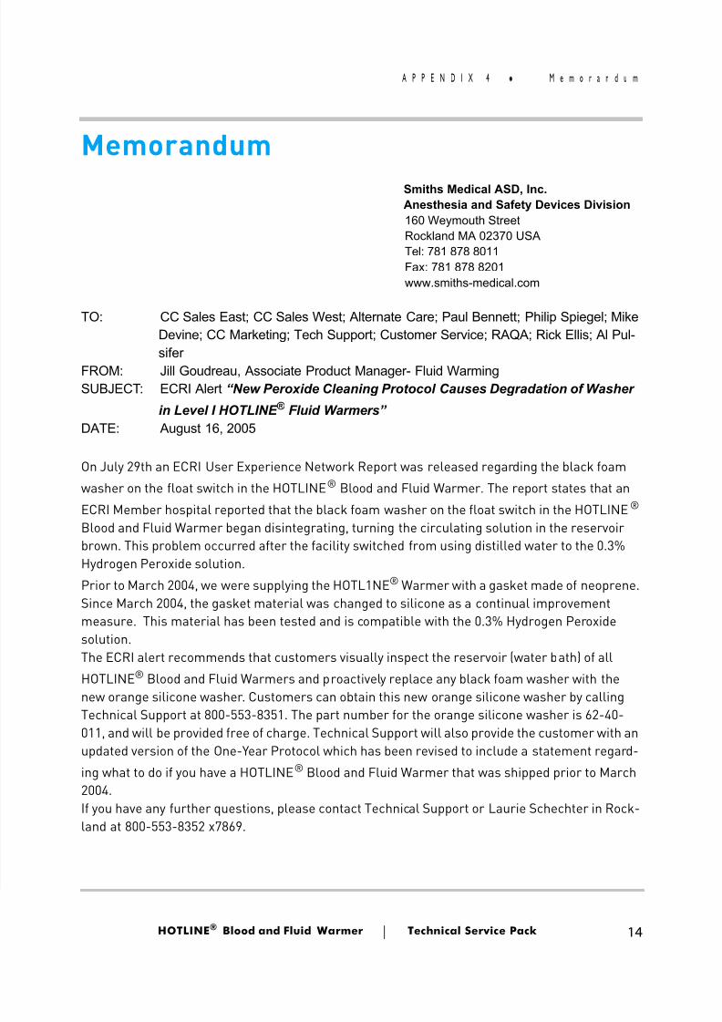
8/13/2019 Smiths Fluid Warmer - General Technical Manual
http://slidepdf.com/reader/full/smiths-fluid-warmer-general-technical-manual 131/131
A P P E N D I X 4 M e m o r a n d u m
MemorandumSmiths Medical ASD, Inc.Anesthesia and Safety Devices Division160 Weymouth StreetRockland MA 02370 USATel: 781 878 8011Fax: 781 878 8201www.smiths-medical.com
TO: CC Sales East; CC Sales West; Alternate Care; Paul Bennett; Philip Spiegel; MikeDevine; CC Marketing; Tech Support; Customer Service; RAQA; Rick Ellis; Al Pul-
siferFROM: Jill Goudreau, Associate Product Manager- Fluid WarmingSUBJECT: ECRI Alert “New Peroxide Cleaning Protocol Causes Degradation of Washer
in Level I HOTLINE ® Fluid Warmers”DATE: August 16, 2005
On July 29th an ECRI User Experience Network Report was released regarding the black foamwasher on the float switch in the HOTLINE ® Blood and Fluid Warmer. The report states that anECRI Member hospital reported that the black foam washer on the float switch in the HOTLINE ®
Blood and Fluid Warmer began disintegrating, turning the circulating solution in the reservoirbrown. This problem occurred after the facility switched from using distilled water to the 0.3%Hydrogen Peroxide solution.Prior to March 2004, we were supplying the HOTL1NE ® Warmer with a gasket made of neoprene.Si M h 2004 th k t t i l h d t ili ti l i t