Embed Size (px)
Citation preview
1
Smoke Duct Slab Erection Gantry and Corbel Anchor Drilling System Design
for the Transcity JV, Legacy Way Road Tunnel Project, Brisbane
Simon Strong, BEng (Mech) Hons
Herrenknecht Australia
Submitted to
The Australasian Tunnelling Society (ATS)
for
The David Sugden Young Engineers Writing Award, 2014
2
1. Abstract
This paper aims to describe the design of two purpose-built machines assisting the construction of a
smoke duct in the Legacy Way tunnel project. The innovative civil design of the smoke duct required
an equally innovative solution for its construction. The engineering team responsible for delivering
the prototype machines endeavoured to solve the problem with simple designs. This paper will
provide a background for the project, describe the specific problem, and then discuss in detail the
development of the design solutions and the challenges faced along the way. The performance of the
final product is also evaluated from a machine design perspective.
2. Project Background
Legacy Way is a twin two-lane, 4.6 km road tunnel project in Brisbane, Australia. Transcity joint
venture (TJV) is the principal contractor managing the design, construction and operation of the
tunnel. Excavation of the 12.4 m diameter tunnels was completed in June 2013, with disassembly of
the Herrenknecht tunnel boring machines (TBMs) and invert backfilling finalised soon thereafter. The
next phase of construction was the installation of a smoke duct system as a part of the tunnel
ventilation scheme. In two previous local projects an entirely cast in situ solution was adopted for the
smoke duct construction. TJV however developed an innovative alternative using a cast in situ corbel
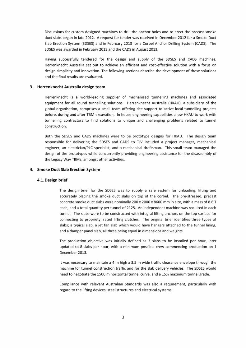
to support precast concrete slab elements. The smoke duct itself is formed by the existing circular
tunnel apex and the installed concrete ceiling, which is continuous along the entire tunnel length
(refer Figure 1).
The following construction process was employed for the smoke duct system:
1. Scabbling of the concrete tunnel segments on each side of the tunnel wall where the corbel
is to be formed
2. Drilling of anchor holes, and subsequent installation of chemically set rebars
3. Installation of a pre-fabricated reinforcement cage, tied to the rebars
4. Pouring of the concrete corbel from a formwork gantry, followed by a curing period
5. Erection of precast smoke duct slabs
6. Final works including sealing, drainage, painting and jet fan hanger installation
Figure 1 – Typical smoke duct cross section
Tunnel segmental lining
Smoke duct slab (typical)
Corbel (with rebar anchors
and reinforcement cage)
3
Discussions for custom designed machines to drill the anchor holes and to erect the precast smoke
duct slabs began in late 2012. A request for tender was received in December 2012 for a Smoke Duct
Slab Erection System (SDSES) and in February 2013 for a Corbel Anchor Drilling System (CADS). The
SDSES was awarded in February 2013 and the CADS in August 2013.
Having successfully tendered for the design and supply of the SDSES and CADS machines,
Herrenknecht Australia set out to achieve an efficient and cost-effective solution with a focus on
design simplicity and innovation. The following sections describe the development of these solutions
and the final results are evaluated.
3. Herrenknecht Australia design team
Herrenknecht is a world-leading supplier of mechanized tunnelling machines and associated
equipment for all round tunnelling solutions. Herrenknecht Australia (HKAU), a subsidiary of the
global organisation, comprises a small team offering site support to active local tunnelling projects
before, during and after TBM excavation. In house engineering capabilities allow HKAU to work with
tunnelling contractors to find solutions to unique and challenging problems related to tunnel
construction.
Both the SDSES and CADS machines were to be prototype designs for HKAU. The design team
responsible for delivering the SDSES and CADS to TJV included a project manager, mechanical
engineer, an electrician/PLC specialist, and a mechanical draftsman. This small team managed the
design of the prototypes while concurrently providing engineering assistance for the disassembly of
the Legacy Way TBMs, amongst other activities.
4. Smoke Duct Slab Erection System
4.1. Design brief
The design brief for the SDSES was to supply a safe system for unloading, lifting and
accurately placing the smoke duct slabs on top of the corbel. The pre-stressed, precast
concrete smoke duct slabs were nominally 200 x 2000 x 8600 mm in size, with a mass of 8.6 T
each, and a total quantity per tunnel of 2125. An independent machine was required in each
tunnel. The slabs were to be constructed with integral lifting anchors on the top surface for
connecting to propriety, rated lifting clutches. The original brief identifies three types of
slabs; a typical slab, a jet fan slab which would have hangers attached to the tunnel lining,
and a damper panel slab, all three being equal in dimensions and weights.
The production objective was initially defined as 3 slabs to be installed per hour, later
updated to 8 slabs per hour, with a minimum possible crew commencing production on 1
December 2013.
It was necessary to maintain a 4 m high x 3.5 m wide traffic clearance envelope through the
machine for tunnel construction traffic and for the slab delivery vehicles. The SDSES would
need to negotiate the 1500 m horizontal tunnel curve, and a ±5% maximum tunnel grade.
Compliance with relevant Australian Standards was also a requirement, particularly with
regard to the lifting devices, steel structures and electrical systems.
4
4.2. Design challenges
Elements of the original design specification were identified as particularly challenging. Slabs
were to be delivered longways, lifted approximately 7 m by the SDSES and once above corbel
level, rotated 90 degrees. The SDSES would then need to drive backwards to accurately
place the slab ahead of its predecessor. The movement of the slab above the corbel was
limited to a very small window, with clashing possible against the tunnel wall and against the
top of the corbel. Design clearances were no greater than 100 mm for movement in any
direction. A low point sump halfway along the tunnel alignment required the SDSES to drive
onto a 70 m long floor level raised 525 mm above the normal road height. The changing
elevation of the road level translated to a changing installation height of the slabs,
compounding the challenge of clash prevention. This section of the tunnel represented only
2% of the total tunnel length, but required careful consideration.
The load bearing capacity of the roadway was also identified as an area of design risk. It
would be necessary to spread the SDSES wheel loads out to prevent any damage to the
permanent civil road works.
Further challenges were introduced after award of the supply contract. The different slab
types changed in size and weight such that the maximum load increased to 10 T. This had
implications for the stability of the structure and for the resultant wheel loads. Adding
counterbalance to resolve the stability ultimately required additional load-balanced wheels
to be installed.
The original delivery date was brought forward by 3 months to allow the SDSES to be
assembled and lifted into the tunnel portal earlier, optimizing crane operations on site. The
shortening of the project timeline added pressure to the fabrication of the steel structures
and the delivery of long lead-time items such as the extra wheel blocks required to distribute
the ground bearing load.
4.3. Solution
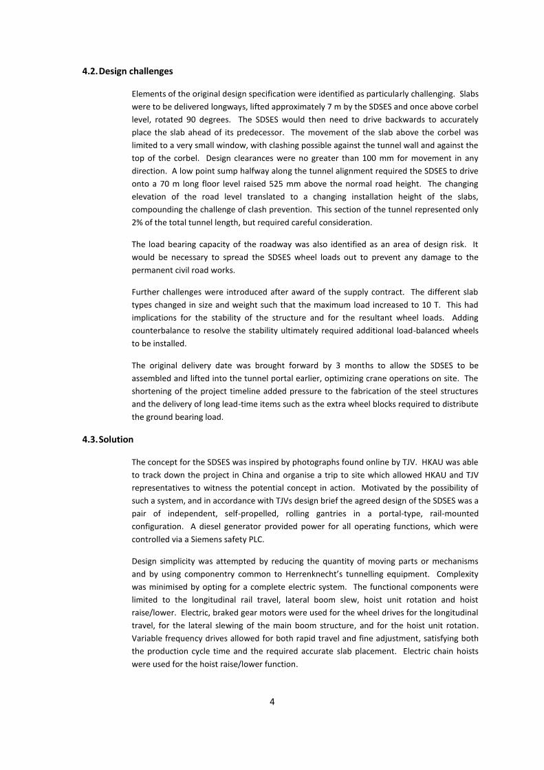
The concept for the SDSES was inspired by photographs found online by TJV. HKAU was able
to track down the project in China and organise a trip to site which allowed HKAU and TJV
representatives to witness the potential concept in action. Motivated by the possibility of
such a system, and in accordance with TJVs design brief the agreed design of the SDSES was a
pair of independent, self-propelled, rolling gantries in a portal-type, rail-mounted
configuration. A diesel generator provided power for all operating functions, which were
controlled via a Siemens safety PLC.
Design simplicity was attempted by reducing the quantity of moving parts or mechanisms
and by using componentry common to Herrenknecht’s tunnelling equipment. Complexity
was minimised by opting for a complete electric system. The functional components were
limited to the longitudinal rail travel, lateral boom slew, hoist unit rotation and hoist
raise/lower. Electric, braked gear motors were used for the wheel drives for the longitudinal
travel, for the lateral slewing of the main boom structure, and for the hoist unit rotation.
Variable frequency drives allowed for both rapid travel and fine adjustment, satisfying both
the production cycle time and the required accurate slab placement. Electric chain hoists
were used for the hoist raise/lower function.
5
The solution for clash prevention relied upon smooth and accurate operator control rather
than sensors or devices. Based on previous experience, particularly while observing
operators use the TBM tunnel segment erector device, it was considered more practical to
use operator skill in favour of engineered limitations and constraints.
The low point sump height change was managed in the structural design without allowance
for jacking of the portal structure or by any other method. This forced the design height of
the hoist unit to be compressed since it needed to be low enough to avoid the tunnel apex
while traversing the low point sump, but high enough to clear the slabs over the corbel while
on normal road level.
The design of the different smoke duct slabs evolved in the early phase of the project. The
mass of the slabs increased, and the structural design, machine stability and ground loading
needed to be reanalysed. Counterweight in the SDSES structure solved the stability, but the
increased mass required that the wheel loads be spread out further on the rails. More wheel
blocks were added, resulting in two-wheel assemblies at the front and three-wheel
assemblies at the rear. The structure required no major additions besides the bogie
assemblies, but the delivery of the additional wheel blocks became critical.
Figure 2 – Inspiration from China
6
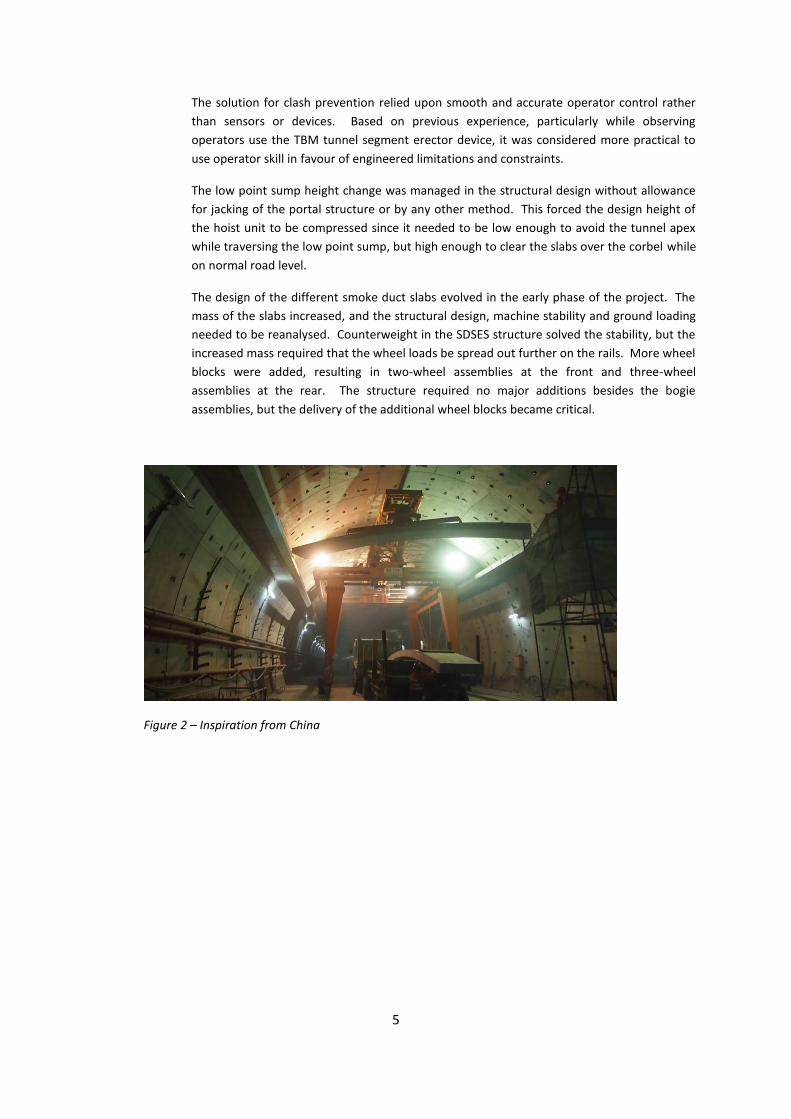
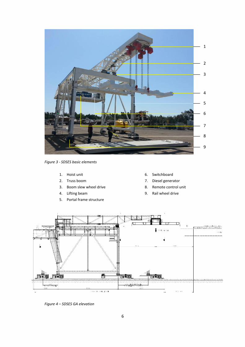
Figure 3 - SDSES basic elements
1. Hoist unit
2. Truss boom
3. Boom slew wheel drive
4. Lifting beam
5. Portal frame structure
6. Switchboard
7. Diesel generator
8. Remote control unit
9. Rail wheel drive
Figure 4 – SDSES GA elevation
1
2
3
4
5
6
7
8
9
7
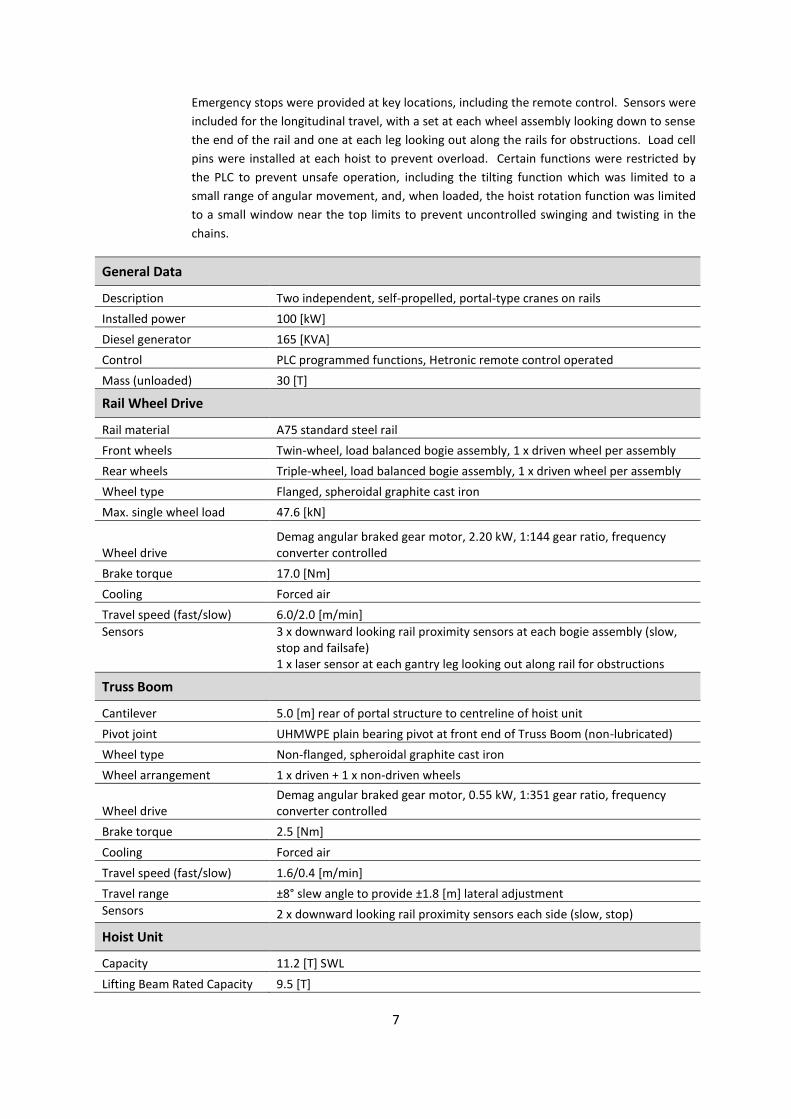
Emergency stops were provided at key locations, including the remote control. Sensors were
included for the longitudinal travel, with a set at each wheel assembly looking down to sense
the end of the rail and one at each leg looking out along the rails for obstructions. Load cell
pins were installed at each hoist to prevent overload. Certain functions were restricted by
the PLC to prevent unsafe operation, including the tilting function which was limited to a
small range of angular movement, and, when loaded, the hoist rotation function was limited
to a small window near the top limits to prevent uncontrolled swinging and twisting in the
chains.
General Data
Description Two independent, self-propelled, portal-type cranes on rails
Installed power 100 [kW]
Diesel generator 165 [KVA]
Control PLC programmed functions, Hetronic remote control operated
Mass (unloaded) 30 [T]
Rail Wheel Drive
Rail material A75 standard steel rail
Front wheels Twin-wheel, load balanced bogie assembly, 1 x driven wheel per assembly
Rear wheels Triple-wheel, load balanced bogie assembly, 1 x driven wheel per assembly
Wheel type Flanged, spheroidal graphite cast iron
Max. single wheel load 47.6 [kN]
Wheel drive Demag angular braked gear motor, 2.20 kW, 1:144 gear ratio, frequency converter controlled
Brake torque 17.0 [Nm]
Cooling Forced air
Travel speed (fast/slow) 6.0/2.0 [m/min]
Sensors 3 x downward looking rail proximity sensors at each bogie assembly (slow, stop and failsafe) 1 x laser sensor at each gantry leg looking out along rail for obstructions
Truss Boom
Cantilever 5.0 [m] rear of portal structure to centreline of hoist unit
Pivot joint UHMWPE plain bearing pivot at front end of Truss Boom (non-lubricated)
Wheel type Non-flanged, spheroidal graphite cast iron
Wheel arrangement 1 x driven + 1 x non-driven wheels
Wheel drive Demag angular braked gear motor, 0.55 kW, 1:351 gear ratio, frequency converter controlled
Brake torque 2.5 [Nm]
Cooling Forced air
Travel speed (fast/slow) 1.6/0.4 [m/min]
Travel range ±8° slew angle to provide ±1.8 [m] lateral adjustment
Sensors 2 x downward looking rail proximity sensors each side (slow, stop)
Hoist Unit
Capacity 11.2 [T] SWL
Lifting Beam Rated Capacity 9.5 [T]
8
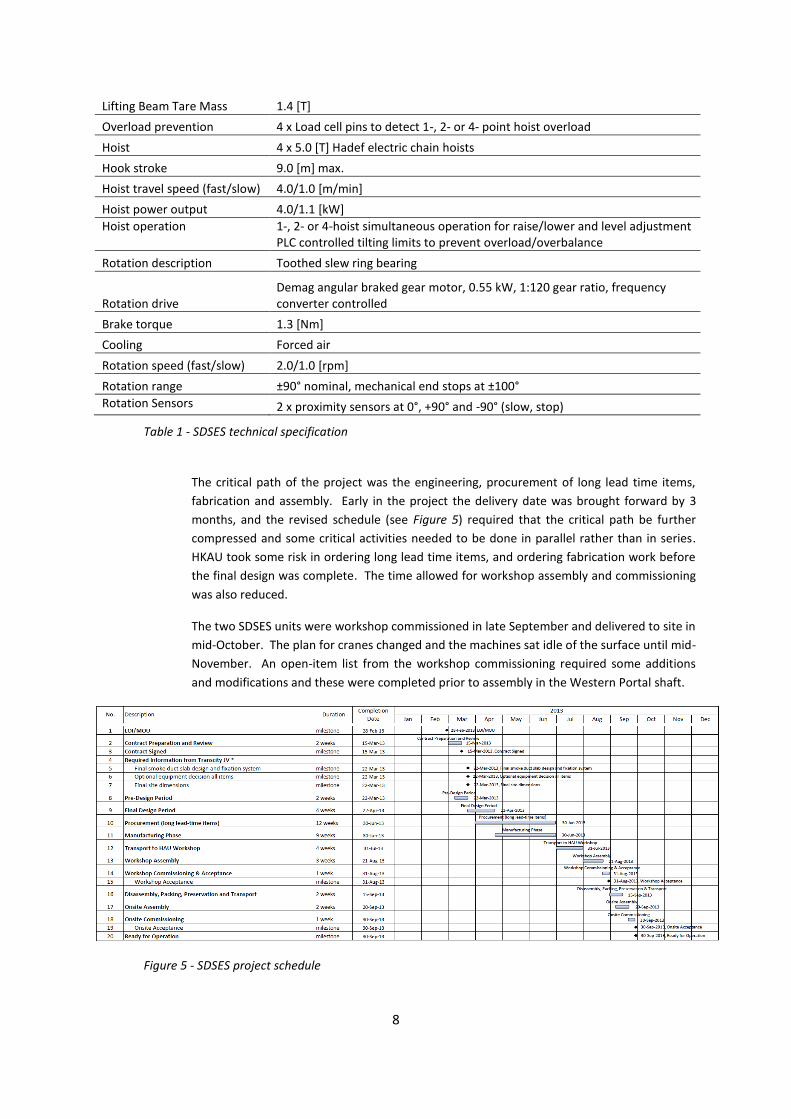
Lifting Beam Tare Mass 1.4 [T]
Overload prevention 4 x Load cell pins to detect 1-, 2- or 4- point hoist overload
Hoist 4 x 5.0 [T] Hadef electric chain hoists
Hook stroke 9.0 [m] max.
Hoist travel speed (fast/slow) 4.0/1.0 [m/min]
Hoist power output 4.0/1.1 [kW]
Hoist operation 1-, 2- or 4-hoist simultaneous operation for raise/lower and level adjustment PLC controlled tilting limits to prevent overload/overbalance
Rotation description Toothed slew ring bearing
Rotation drive Demag angular braked gear motor, 0.55 kW, 1:120 gear ratio, frequency converter controlled
Brake torque 1.3 [Nm]
Cooling Forced air
Rotation speed (fast/slow) 2.0/1.0 [rpm]
Rotation range ±90° nominal, mechanical end stops at ±100°
Rotation Sensors 2 x proximity sensors at 0°, +90° and -90° (slow, stop)
Table 1 - SDSES technical specification
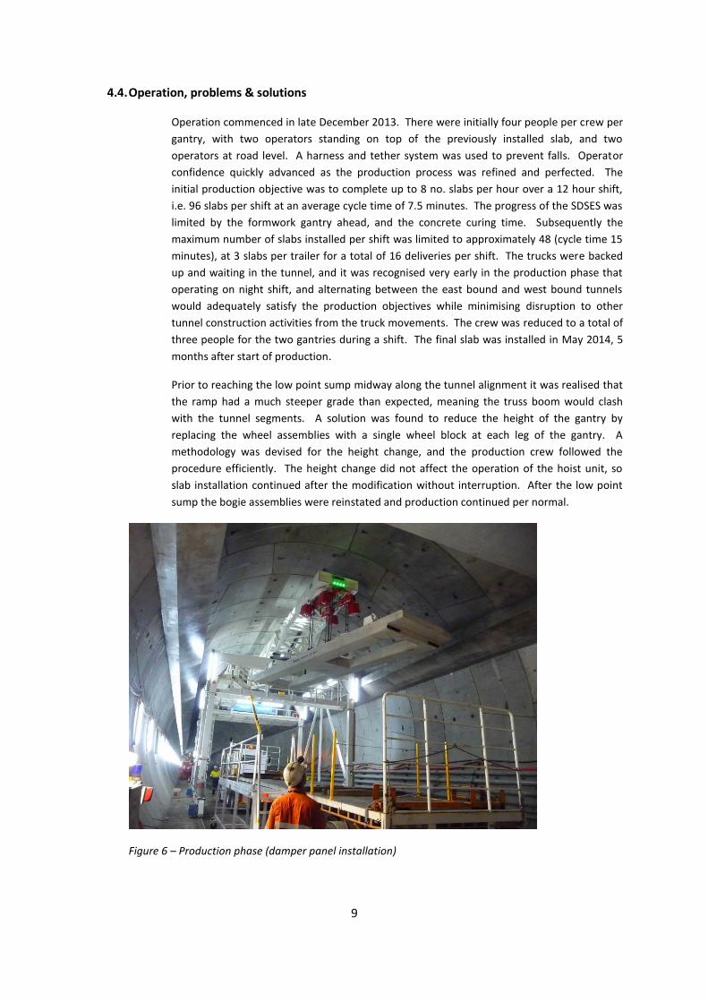
The critical path of the project was the engineering, procurement of long lead time items,
fabrication and assembly. Early in the project the delivery date was brought forward by 3
months, and the revised schedule (see Figure 5) required that the critical path be further
compressed and some critical activities needed to be done in parallel rather than in series.
HKAU took some risk in ordering long lead time items, and ordering fabrication work before
the final design was complete. The time allowed for workshop assembly and commissioning
was also reduced.
The two SDSES units were workshop commissioned in late September and delivered to site in
mid-October. The plan for cranes changed and the machines sat idle of the surface until mid-
November. An open-item list from the workshop commissioning required some additions
and modifications and these were completed prior to assembly in the Western Portal shaft.
Figure 5 - SDSES project schedule
9
4.4. Operation, problems & solutions
Operation commenced in late December 2013. There were initially four people per crew per
gantry, with two operators standing on top of the previously installed slab, and two
operators at road level. A harness and tether system was used to prevent falls. Operator
confidence quickly advanced as the production process was refined and perfected. The
initial production objective was to complete up to 8 no. slabs per hour over a 12 hour shift,
i.e. 96 slabs per shift at an average cycle time of 7.5 minutes. The progress of the SDSES was
limited by the formwork gantry ahead, and the concrete curing time. Subsequently the
maximum number of slabs installed per shift was limited to approximately 48 (cycle time 15
minutes), at 3 slabs per trailer for a total of 16 deliveries per shift. The trucks were backed
up and waiting in the tunnel, and it was recognised very early in the production phase that
operating on night shift, and alternating between the east bound and west bound tunnels
would adequately satisfy the production objectives while minimising disruption to other
tunnel construction activities from the truck movements. The crew was reduced to a total of
three people for the two gantries during a shift. The final slab was installed in May 2014, 5
months after start of production.
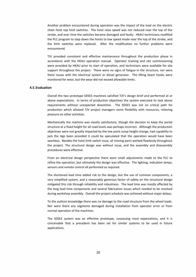
Prior to reaching the low point sump midway along the tunnel alignment it was realised that
the ramp had a much steeper grade than expected, meaning the truss boom would clash
with the tunnel segments. A solution was found to reduce the height of the gantry by
replacing the wheel assemblies with a single wheel block at each leg of the gantry. A
methodology was devised for the height change, and the production crew followed the
procedure efficiently. The height change did not affect the operation of the hoist unit, so
slab installation continued after the modification without interruption. After the low point
sump the bogie assemblies were reinstated and production continued per normal.
Figure 6 – Production phase (damper panel installation)
10
Another problem encountered during operation was the impact of the load on the electric
chain hoist top limit switches. The hoist raise speed was not reduced near the top of the
stroke, and over time the switches became damaged and faulty. HKAU technicians modified
the PLC program to step down the hoists to low speed mode near the top of the stroke, and
the limit switches were replaced. After the modification no further problems were
encountered.
TJV provided consistent and effective maintenance throughout the production phase in
accordance with the HKAU operation manual. Operator training and site commissioning
were provided by HKAU prior to start of operation, and technicians were available for site
support throughout the project. There were no signs of fatigue in the structure, nor were
there issues with the electrical system or diesel generator. The lifting beam hooks were
monitored for wear, but the wear did not exceed allowable limits.
4.5. Evaluation
Overall the two prototype SDSES machines satisfied TJV’s design brief and performed at or
above expectations. In terms of production objectives the system executed its task above
requirements without unexpected downtime. The SDSES was not on critical path for
production which allowed TJV project managers some flexibility with resources, relieving
pressure on other activities.
Mechanically the machine was mostly satisfactory, though the decision to keep the portal
structure at a fixed height for all road levels was perhaps incorrect. Although the production
objectives were not greatly impacted by the low point sump height change, had capability to
jack the legs been provided it could be speculated that the operation would have been
seamless. Besides the hoist limit switch issue, all moving parts worked flawlessly throughout
the project. The structural design was without issue, and the assembly and disassembly
procedures were effective.
From an electrical design perspective there were small adjustments made to the PLC to
refine the operation, but ultimately the design was effective. The lighting, indication lamps,
sensors and remote control all performed as required.
The shortened lead time added risk to the design, but the use of common components, a
very simplified system, and a reasonably generous factor of safety on the structural design
mitigated this risk through reliability and robustness. The lead time was mostly affected by
the long lead time components and several fabrication issues which needed to be resolved
during workshop assembly. Overall the project schedule was achieved without major delays.
To the authors knowledge there was no damage to the road structure from the wheel loads.
Nor were there any segments damaged during installation from operator error or from
normal operation of the machines.
The SDSES system was an effective prototype, surpassing most expectations, and it is
conceivable that a precedent has been set for similar systems to be used in future
applications.
11
5. Corbel Anchor Drilling System
5.1. Design brief
The CADS design brief was to supply a semi-automated system for accurately drilling a
prescribed radial pattern of holes in the tunnel segmental lining. The drilling pattern
consisted of a quantity of 12, 25 mm diameter, 300 mm deep anchor holes on each side of
the tunnel per 2 m wide tunnel ring, with a bottom and top row of 6 holes each. A total of
approximately 51,000 holes were required per tunnel. An independent rolling gantry was to
be provided by TJV for each tunnel, upon which the drilling system was to be installed. A
variety of drilling patterns were initially specified, with accurate hole positions required to
avoid the internal steel reinforcement. The range of hole positions required fine adjustment
of the CADS vertically, longitudinally and angularly.
The drill position was to be firmly maintained during the drilling operation, and once the
required hole depth was achieved, the drill was to be retracted automatically. The 300 mm
drill depth needed to be accurately controlled. In the event of hitting reinforcement bar it
was required that the drill stop and be manually retracted before causing damage to the drill
bit.
The production objective was defined as 20 tunnel rings to be drilled per shift, or 480 holes,
at an average of 1.5 minutes per hole. At this high rate of production it was determined that
8 independent drilling rigs would be required, 4 each side of the tunnel, with 2 to complete
the top row and 2 to complete the bottom row of holes. A crew of 4 people per gantry was
to commence production in late October 2013.
5.2. Design challenges
Per the SDSES the CADS was also required to operate within the tunnel construction
tolerances, horizontal and vertical curves, and the low point sump height change. The
gantry, supplied by UniSpan, also had its own inherent flexibility. Maintaining the tight
tolerances on the hole positions and angles, coupled with the required production rate was
the major design challenge for this project.
Development of a prototype system was a design challenge, and producing 16 independent
drilling rigs within the project timeline and ready for production multiplied the magnitude of
this challenge.
5.3. Solution
The basic solution for the CADS was a set of 8 custom-designed, independent, semi-
automatic drilling rigs per tunnel, mounted on a UniSpan portal-type, rail-mounted gantry
structure (gantry supplied by TJV). Each rig was equipped with an electric Hilti percussive
drill, and a Hilti dustless system incorporating a hollow drill bit and vacuum unit (supplied by
TJV). Each drilling unit could be shifted manually and independently in the longitudinal
direction along floor mounted rails, with the rail length allowing 4 tunnel segments to be
drilled with each consecutive advance of the gantry. Height adjustment was provided in two
ways. An innovative manual raising/lowering system was included to adjust the rig height
only over the low point sump area. This system was designed as an inexpensive method
which eliminated manual lifting. For regular operational height adjustment an electric ball
screw linear actuator was provided to drive a parallel linkage mechanism. Angular
12
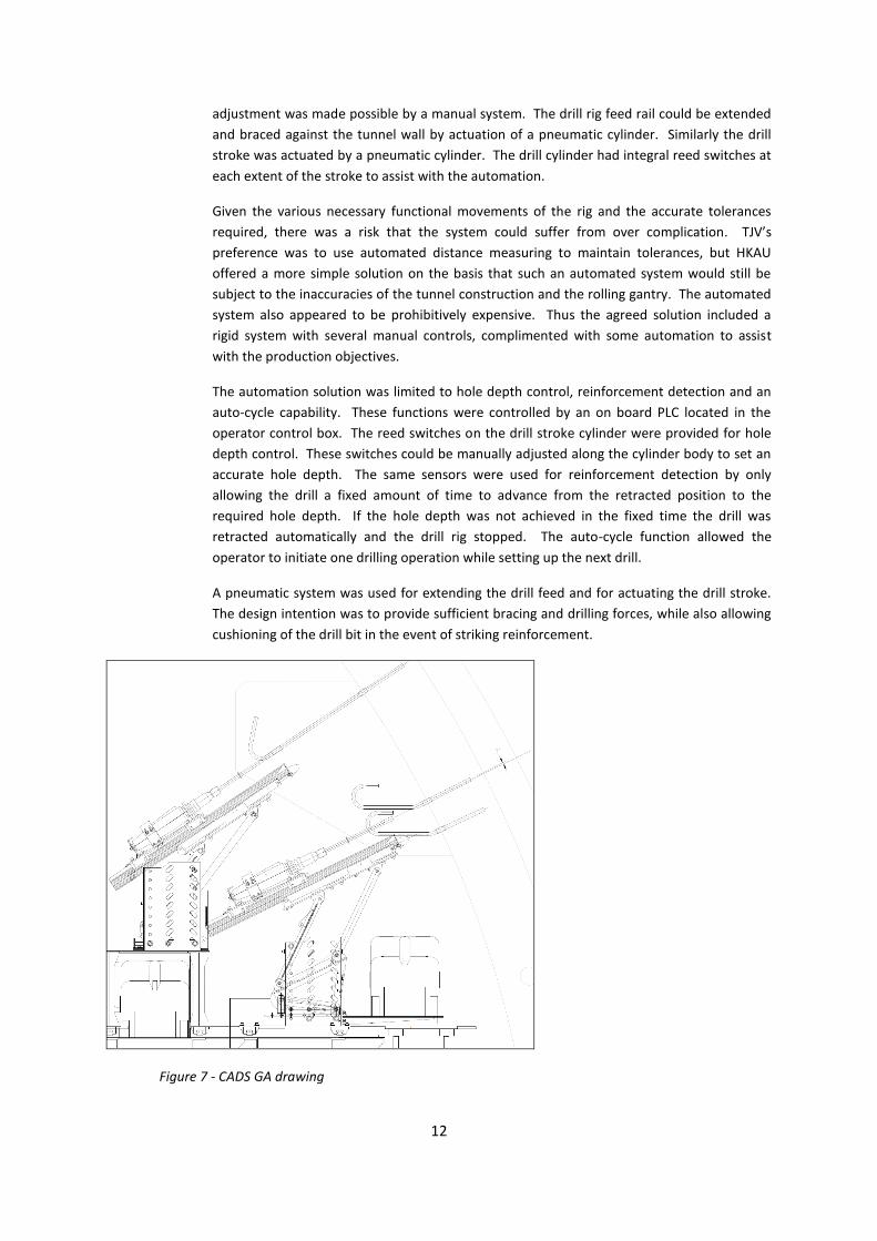
adjustment was made possible by a manual system. The drill rig feed rail could be extended
and braced against the tunnel wall by actuation of a pneumatic cylinder. Similarly the drill
stroke was actuated by a pneumatic cylinder. The drill cylinder had integral reed switches at
each extent of the stroke to assist with the automation.
Given the various necessary functional movements of the rig and the accurate tolerances
required, there was a risk that the system could suffer from over complication. TJV’s
preference was to use automated distance measuring to maintain tolerances, but HKAU
offered a more simple solution on the basis that such an automated system would still be
subject to the inaccuracies of the tunnel construction and the rolling gantry. The automated
system also appeared to be prohibitively expensive. Thus the agreed solution included a
rigid system with several manual controls, complimented with some automation to assist
with the production objectives.
The automation solution was limited to hole depth control, reinforcement detection and an
auto-cycle capability. These functions were controlled by an on board PLC located in the
operator control box. The reed switches on the drill stroke cylinder were provided for hole
depth control. These switches could be manually adjusted along the cylinder body to set an
accurate hole depth. The same sensors were used for reinforcement detection by only
allowing the drill a fixed amount of time to advance from the retracted position to the
required hole depth. If the hole depth was not achieved in the fixed time the drill was
retracted automatically and the drill rig stopped. The auto-cycle function allowed the
operator to initiate one drilling operation while setting up the next drill.
A pneumatic system was used for extending the drill feed and for actuating the drill stroke.
The design intention was to provide sufficient bracing and drilling forces, while also allowing
cushioning of the drill bit in the event of striking reinforcement.
Figure 7 - CADS GA drawing
13
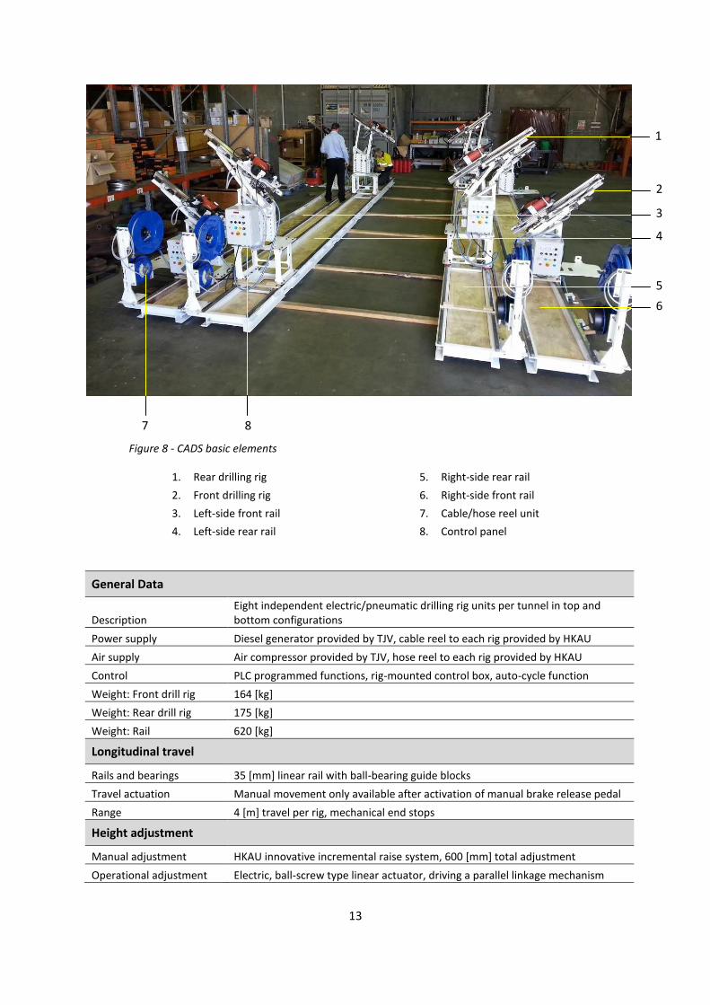
Figure 8 - CADS basic elements
1. Rear drilling rig
2. Front drilling rig
3. Left-side front rail
4. Left-side rear rail
5. Right-side rear rail
6. Right-side front rail
7. Cable/hose reel unit
8. Control panel
General Data
Description Eight independent electric/pneumatic drilling rig units per tunnel in top and bottom configurations
Power supply Diesel generator provided by TJV, cable reel to each rig provided by HKAU
Air supply Air compressor provided by TJV, hose reel to each rig provided by HKAU
Control PLC programmed functions, rig-mounted control box, auto-cycle function
Weight: Front drill rig 164 [kg]
Weight: Rear drill rig 175 [kg]
Weight: Rail 620 [kg]
Longitudinal travel
Rails and bearings 35 [mm] linear rail with ball-bearing guide blocks
Travel actuation Manual movement only available after activation of manual brake release pedal
Range 4 [m] travel per rig, mechanical end stops
Height adjustment
Manual adjustment HKAU innovative incremental raise system, 600 [mm] total adjustment
Operational adjustment Electric, ball-screw type linear actuator, driving a parallel linkage mechanism
3
4
5
6
7 8
2
1
14
Feed extension
Actuation 32 [mm] bore, 600 [mm] stroke pneumatic cylinder
Rails and bearings 35 [mm] linear rail with ball-bearing guide blocks
Drill stroke
Actuation 32 [mm] bore, 400 [mm] stroke pneumatic cylinder
Rails and bearings 35 [mm] linear rail with ball-bearing guide blocks
Dustless drill system
Drill Hilti TE70 electric hammer drill
Drill bit Ø25 [mm] tungsten carbide tipped hollow drill bit with vacuum attachment
Vacuum Hilti vacuum
Table 2 – CADS technical specification
5.4. Operation, problems & solutions
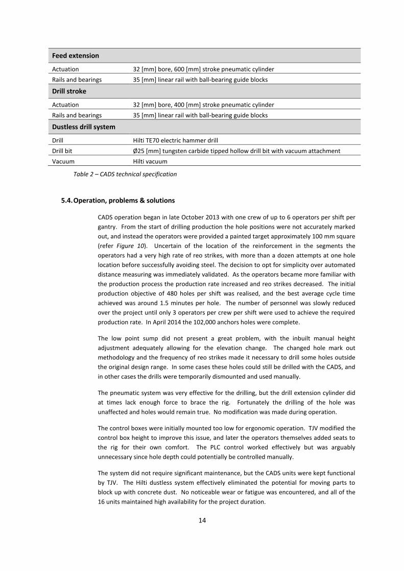
CADS operation began in late October 2013 with one crew of up to 6 operators per shift per
gantry. From the start of drilling production the hole positions were not accurately marked
out, and instead the operators were provided a painted target approximately 100 mm square
(refer Figure 10). Uncertain of the location of the reinforcement in the segments the
operators had a very high rate of reo strikes, with more than a dozen attempts at one hole
location before successfully avoiding steel. The decision to opt for simplicity over automated
distance measuring was immediately validated. As the operators became more familiar with
the production process the production rate increased and reo strikes decreased. The initial
production objective of 480 holes per shift was realised, and the best average cycle time
achieved was around 1.5 minutes per hole. The number of personnel was slowly reduced
over the project until only 3 operators per crew per shift were used to achieve the required
production rate. In April 2014 the 102,000 anchors holes were complete.
The low point sump did not present a great problem, with the inbuilt manual height
adjustment adequately allowing for the elevation change. The changed hole mark out
methodology and the frequency of reo strikes made it necessary to drill some holes outside
the original design range. In some cases these holes could still be drilled with the CADS, and
in other cases the drills were temporarily dismounted and used manually.
The pneumatic system was very effective for the drilling, but the drill extension cylinder did
at times lack enough force to brace the rig. Fortunately the drilling of the hole was
unaffected and holes would remain true. No modification was made during operation.
The control boxes were initially mounted too low for ergonomic operation. TJV modified the
control box height to improve this issue, and later the operators themselves added seats to
the rig for their own comfort. The PLC control worked effectively but was arguably
unnecessary since hole depth could potentially be controlled manually.
The system did not require significant maintenance, but the CADS units were kept functional
by TJV. The Hilti dustless system effectively eliminated the potential for moving parts to
block up with concrete dust. No noticeable wear or fatigue was encountered, and all of the
16 units maintained high availability for the project duration.
15
Figure 10 – CADS Production phase, reinforcement strikes
5.5. Evaluation
Mechanically the system proved reliable, however the adjustment of the drilling angle
needed to be improved to simplify this function. The linear rails and guide blocks, normally
used in precision machines, were highly successful and required very little maintenance.
The dustless drill system contributed greatly to the CADS success. Smooth operation of the
mechanical parts would have been greatly reduced had concrete dust been an issue in the
working environment.
The CADS electric system performed satisfactorily. The hole depth control was accurate to
within 5 mm, and the auto-cycle effectively allowed the operators to control multiple rigs
simultaneously. Drill retraction after labouring on reinforcement was valuable for
maximising drill bit life.
Future improvements would see easier angular adjustment, and an increase in the drill feed
extension cylinder bore diameter to ensure firm bracing. The use of PLC control and auto-
cycling would need to be assessed for its benefit. The control box position required more
considered ergonomic design.
As a prototype system the CADS performed above expectations and completed the project
on time and without major problems. Off the back of the success of the CADS, two separate,
non-PLC controlled rigs were later ordered by TJV for drilling the jet fan hanger brackets
above the smoke duct. These new rigs had simple pneumatic controls, and also completed
their task satisfactorily and without operational issues (refer Figure 11).
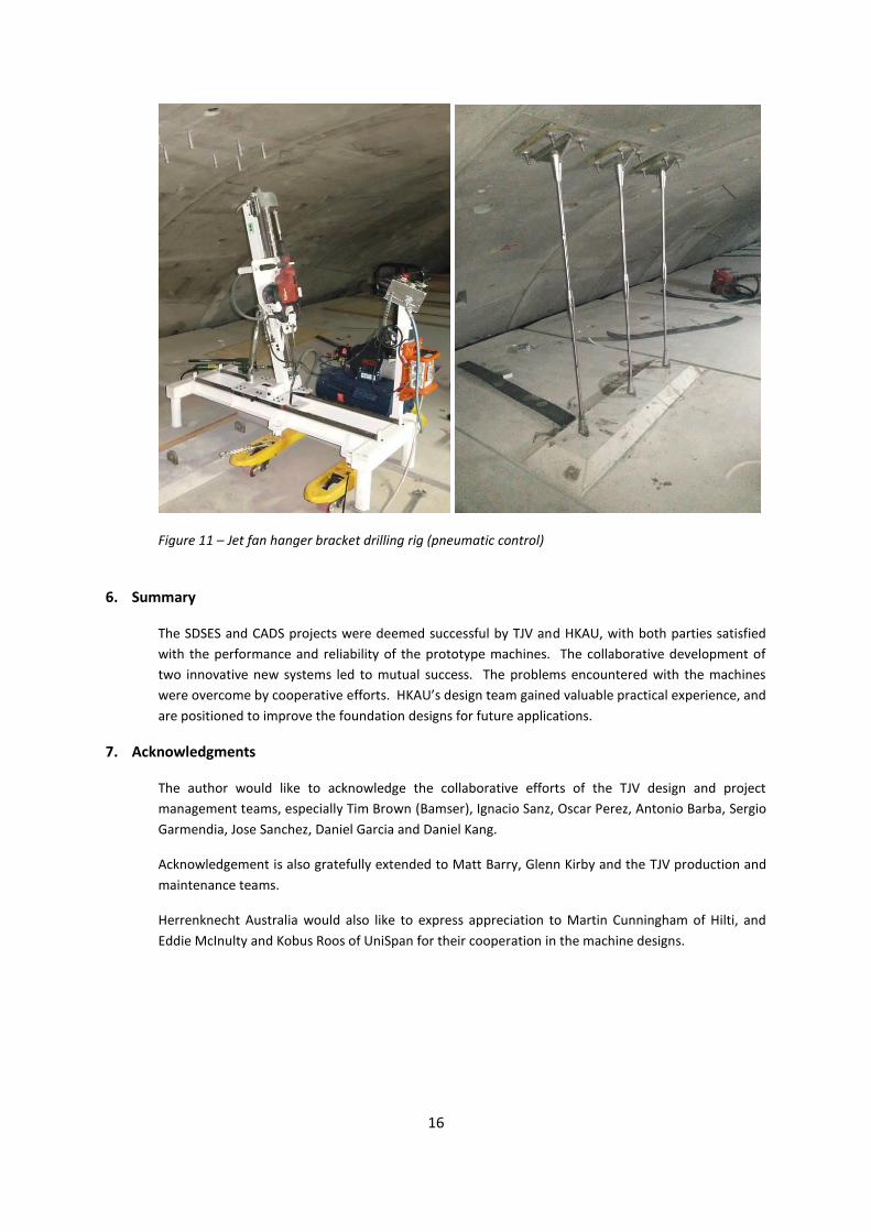
16
Figure 11 – Jet fan hanger bracket drilling rig (pneumatic control)
6. Summary
The SDSES and CADS projects were deemed successful by TJV and HKAU, with both parties satisfied
with the performance and reliability of the prototype machines. The collaborative development of
two innovative new systems led to mutual success. The problems encountered with the machines
were overcome by cooperative efforts. HKAU’s design team gained valuable practical experience, and
are positioned to improve the foundation designs for future applications.
7. Acknowledgments
The author would like to acknowledge the collaborative efforts of the TJV design and project
management teams, especially Tim Brown (Bamser), Ignacio Sanz, Oscar Perez, Antonio Barba, Sergio
Garmendia, Jose Sanchez, Daniel Garcia and Daniel Kang.
Acknowledgement is also gratefully extended to Matt Barry, Glenn Kirby and the TJV production and
maintenance teams.
Herrenknecht Australia would also like to express appreciation to Martin Cunningham of Hilti, and
Eddie McInulty and Kobus Roos of UniSpan for their cooperation in the machine designs.