Embed Size (px)
Citation preview
8/8/2019 Sms Automation 122222
http://slidepdf.com/reader/full/sms-automation-122222 1/15
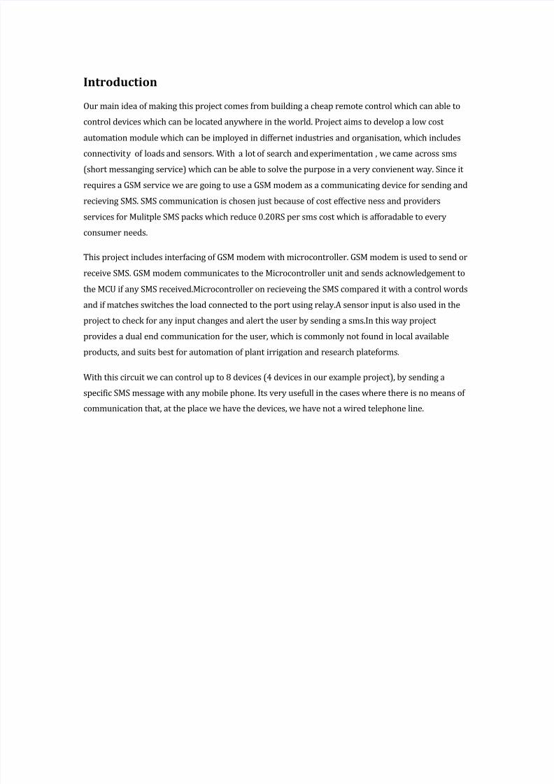
Introduction
Our main idea of making this project comes from building a cheap remote control which can able to
control devices which can be located anywhere in the world. Project aims to develop a low cost
automation module which can be imployed in differnet industries and organisation, which includes
connectivity of loads and sensors. With a lot of search and experimentation , we came across sms
(short messanging service) which can be able to solve the purpose in a very convienent way. Since it
requires a GSM service we are going to use a GSM modem as a communicating device for sending and
recieving SMS. SMS communication is chosen just because of cost effective ness and providers
services for Mulitple SMS packs which reduce 0.20RS per sms cost which is afforadable to every
consumer needs.
This project includes interfacing of GSM modem with microcontroller. GSM modem is used to send or
receive SMS. GSM modem communicates to the Microcontroller unit and sends acknowledgement tothe MCU if any SMS received.Microcontroller on recieveing the SMS compared it with a control words
and if matches switches the load connected to the port using relay.A sensor input is also used in the
project to check for any input changes and alert the user by sending a sms.In this way project
provides a dual end communication for the user, which is commonly not found in local available
products, and suits best for automation of plant irrigation and research plateforms.
With this circuit we can control up to 8 devices (4 devices in our example project), by sending a
specific SMS message with any mobile phone. Its very usefull in the cases where there is no means of
communication that, at the place we have the devices, we have not a wired telephone line.
8/8/2019 Sms Automation 122222
http://slidepdf.com/reader/full/sms-automation-122222 2/15
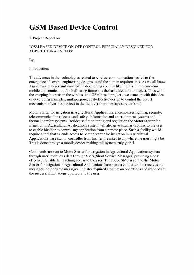
GSM Based Device Control
A Project Report on
³GSM BASED DEVICE ON-OFF CONTROL ESPECIALLY DESIGNED FOR AGRICULTURAL NEEDS´
By,
Introduction:
The advances in the technologies related to wireless communication has led to the
emergence of several engineering designs to aid the human requirements. As we all knowAgriculture play a significant role in developing country like India and implementing
mobile communication for facilitating farmers is the basic idea of our project. Thus with
the creeping interests in the wireless and GSM based projects, we came up with this ideaof developing a simpler, multipurpose, cost-effective design to control the on-off mechanism of various devices in the field via short message service (sms).
Motor Starter for irrigation in Agricultural Applications encompasses lighting, security,telecommunications, access and safety, information and entertainment systems and
thermal comfort systems. Besides self monitoring and regulation the Motor Starter for irrigation in Agricultural Applications system will also give auxiliary control to the user
to enable him/her to control any application from a remote place. Such a facility wouldrequire a tool that extends access to Motor Starter for irrigation in Agricultural
Applications base station controller from his/her premises to anywhere the user might be.
This is done through a mobile device making this system truly global.
Commands are sent to Motor Starter for irrigation in Agricultural Applications system
through user¶ mobile as data through SMS (Short Service Messages) providing a costeffective, reliable far reaching access to the user. The coded SMS is sent to the Motor
Starter for irrigation in Agricultural Applications base station controller that receives themessages, decodes the messages, initiates required automation operations and responds to
the successful initiations by a reply to the user.
8/8/2019 Sms Automation 122222
http://slidepdf.com/reader/full/sms-automation-122222 3/15
Abstract:
Our project is based on ³GSM technology´ used for long distant communication. Thedesign portion involves mainly a GSM modem and a control circuitry with
microcontroller and Max232N etc«
ZFor doing this project we use some of the software like Embedded C for programmingthe application software to the microcontroller. Protel schematic software is used for
designing the circuit diagramZ for this project. Express PCB software is used for
designing the PCB for this project.Z (Since PCB making is a big process and involves lotof machineries, which are expensive, we are going to outsource this to the manufacturer.)
In our design we are implementing a Motor Starter for irrigation in AgriculturalApplications and security systems using GSM,GSM is one of the latest mobile
technologies using smart MODEM which can easily interfaced to embeddedmicrocontrollers.
Now everything is going to be automated using this technology, using this technology we
can access the devices remotely. Motor Starter for irrigation in Agricultural Applicationsencompasses lighting, security, telecommunications, access and safety, information and
entertainment systems and thermal comfort systems. Besides self monitoring andregulation the Motor Starter for irrigation in Agricultural Applications system will also
give auxiliary control to the user to enable him/her to control any application from aremote place. Such a facility would require a tool that extends access to Motor Starter for
irrigation in Agricultural Applications base station controller from his/her premises toanywhere the user might be. This is done through a mobile device making this system
truly global.
This project is now developed by us as a multipurpose project which can be used for
controlling of lights and other electronic devices in home, offices etc. and for varioustime saving and manual effort preserving tasks that can be accomplished via sms.

8/8/2019 Sms Automation 122222
http://slidepdf.com/reader/full/sms-automation-122222 4/15
Components used:
Z Power Supply 5v DC - 7805 Z Microcontroller - 89S52Atmel Z Crystal - 11.0592MHz
Z MAX232 - Serial Communication Z Motor Starter Z GSM Transmitter and Receiver (MODEM)
Power supply: The microcontroller and other devices get power supply from AC to Dc
adapter through 7805, 5 volts regulator. The adapter output voltage will be 12V DC non-regulated. The 7805/7812 voltage regulators are used to convert 12 V to 5V/12V DC.
Micro controller-AT89S52: The AT89S52 is a low-power, high-performance CMOS 8-
bit microcontroller with 8K bytes of in-system programmable Flash memory. The deviceis manufactured using Atmel¶s high-density nonvolatile memory technology and is
compatible with the industry- standard 80C51 instruction set and pin out. Features: 8K Bytes of In-System Programmable (ISP) Flash Memory Endurance: 1000 Write/Erase
Cycles 4.0V to 5.5V Operating Range 256 x 8-bit Internal RAM 32 ProgrammableI/O Lines Full Duplex UART Serial Channel Fully Static Operation: 0 Hz to 33 MHz
RS 232 CONVERTER (MAX 232N) Serial Port: This is the device, which is used to
convert TTL/RS232 vice versa. RS-232 pin-outs for IBM compatible computers areshown below. There are two configurations that are typically used: one for a 9-pin
connector and the other for a 25-pin connector.
The standard voltage range on RS-232 pins is _15V to +15V. This voltage range applies
to all RS-232 signal pins. The total voltage swing during signal transmission can be aslarge as 30V. In many cases, RS-232 ports will operate with voltages as low as _5V to
+5V. This wide range of voltages allows for better compatibility between different typesof equipment and allows greater noise margin to avoid interference. Because the voltage
swing on RS-232 lines is so large, the RS-232 signal lines generate a significant amountof electrical noise. It is important that this signal does not run close to high impedance
microphone lines or audio lines in a system. In cases where you must run these types of signals nearby one another, it is important to make sure that all audio wires are properly
shielded. The main role of the RS232 chip is to convert the data coming for the 12-voltlogic to 5 volt logic and from 5 volt logic to 12 volt logic
GSM modem (900/1800 MHz) Semen¶s GSM/GPRS Smart Modem is a multi-functional,ready to use, rugged unit that can be embedded or plugged into any application. The
Smart Modem can be controlled and customized to various levels by using the standardAT commands. The modem is fully type-approved, it can speed up the operational time
with full range of Voice, Data, Fax and Short Messages (Point to Point and CellBroadcast), the modem also supports GPRS (Class 2*) for spontaneous data transfer.
Description of the interfaces The modem comprises several interfaces: - LED Function

8/8/2019 Sms Automation 122222
http://slidepdf.com/reader/full/sms-automation-122222 5/15
including operating Status - External antenna ( via SMA) - Serial and control link -Power Supply ( Via 2 pin Phoenix tm contact ) - SIM card holder
LED Status Indicator The LED will indicate different status of the modem: - OFF
Modem Switched off - ON Modem is connecting to the network - Flashing Slowly
Modem is in idle mode Flashing rapidly Modem is in transmission/communication (GSMonly) SIM300 AT Command Set In application, controlling device controls the GSMengine by sending AT Command via its serial interface. The controlling device at the
other end of the serial line is referred to as following term: 1) TE (Terminal Equipment);2) DTE (Data Terminal Equipment) AT Command syntax The "AT" or "at" prefix must
be set at the beginning of each command line. To terminate a command line enter <CR>.Commands are usually followed by a response that
includes.´<CR><LF><response><CR><LF>´ The AT command set implemented bySIM300 is a combination of GSM07.05, GSM07.07 and ITU-T recommendation V.25ter
and the AT commands developed by SIMCOM. Note: Only enter AT command throughserial port after SIM300 is power on and Unsolicited Result Code ³RDY´ is received
from serial port. And if unsolicited result code´SCKS: 0´ returned it indicates SIM cardisn¶t present. If autobauding is enabled, the Unsolicited Result Codes ³RDY´ and so on
are not indicated when you start up
Types of AT commands and responses
Test command AT+<x>=? The mobile equipment returns the list of parameters and value
ranges set with the corresponding Write command or by internal processes. Readcommand AT+<x>? This command returns the currently set value of the parameter or
parameters. Write command AT+<x>=<«> This command sets the user-definable parameter values. Execution command AT+<x> The execution command reads non-
variable parameters affected by internal processes in the GSM engine
Flow control is very important for correct communication between the GSM engine andDTE. For in the case such as a data or fax call, the sending device is transferring data
faster than the receiving side is ready to accept. When the receiving buffer reaches itscapacity, the receiving device should be capable to cause the sending device to pause
until it catches up. There are basically two approaches to achieve data flow control:software flow control and hardware flow control. SIM300 support both two kinds of flow
control.

8/8/2019 Sms Automation 122222
http://slidepdf.com/reader/full/sms-automation-122222 6/15
Applications
1. As a monitoring a control tool in industries.
2. Bio-monitoring for a patients.
3. Security controls.
4. Vehicle locks.
5. As a remote control for pump and generators.
With this circuit one can switch-ON , OFF or Restart some Linux servers, ADSL modems, Printers,
Door with electric lock , Garage door, House lights, Water
pumps, electric sunshade, Block the engine of your car or your motorcycle, at the steal case andmuch more. The purpose of this circuit is to make the human life better and easier.
Block Diagram
GSM
ModemMicro
Controller
Unit
Relay
Unit
Appliances
Sensor
8/8/2019 Sms Automation 122222
http://slidepdf.com/reader/full/sms-automation-122222 7/15
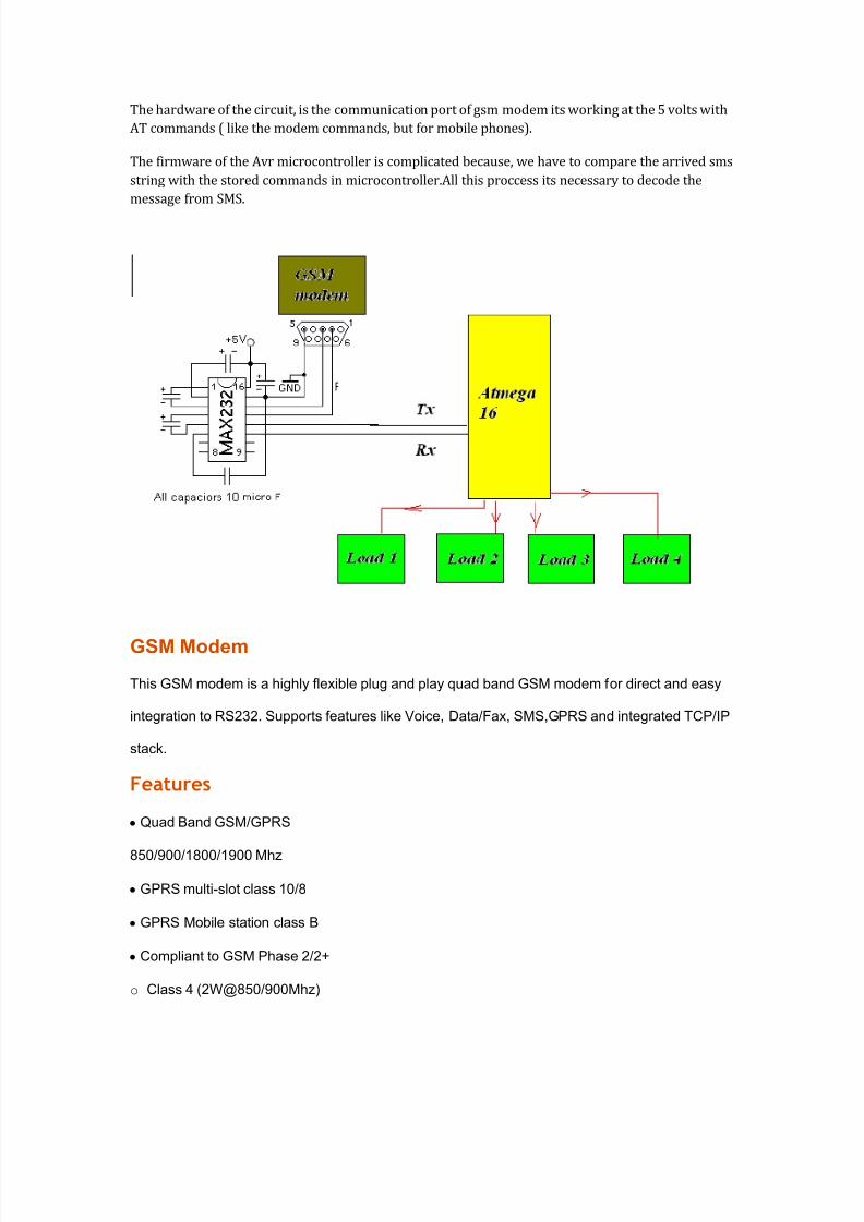
The hardware of the circuit, is the communication port of gsm modem its working at the 5 volts with
AT commands ( like the modem commands, but for mobile phones).
The firmware of the Avr microcontroller is complicated because, we have to compare the arrived sms
string with the stored commands in microcontroller.All this proccess its necessary to decode the
message from SMS.
GSM Modem
This GSM modem is a highly flexible plug and play quad band GSM modem for direct and easy
integration to RS232. Supports features like Voice, Data/Fax, SMS,GPRS and integrated TCP/IP
stack.
Features
yQuad Band GSM/GPRS
850/900/1800/1900 Mhz
yGPRS multi-slot class 10/8
yGPRS Mobile station class B
yCompliant to GSM Phase 2/2+
o Class 4 (2W@850/900Mhz)
8/8/2019 Sms Automation 122222
http://slidepdf.com/reader/full/sms-automation-122222 8/15
o Class 1(1W@1800/1900Mhz)
yControl via AT commands(GSM 07.07,
07.05 and enhanced AT commands)
2
Specifications for SMS
yPoint-to-point MO and MT
ySMS cell broadcast
yText and PDU mode
Power Supply
yUse AC ± DC Power Adaptor with following ratings
yDC Voltage : 12V
yDC Current : 1A
yPolarity : Centre +ve & Outside ±ve
yCurrent Consumption in normal operation 250mA, can rise up to 1Amp while transmission.
Interfaces
yRS-232 through D-TYPE 9 pin connector, Serial port baud rate adjustable 1200 to115200
bps (9600 default)
yStereo connector for MIC & SPK
yPower supply through DC socket
ySMA antenna connector
yPush switch type SIM holder
yLED status of GSM / GPRS module
8/8/2019 Sms Automation 122222
http://slidepdf.com/reader/full/sms-automation-122222 9/15
UART
UART (Universal Asynchronous Receiver Transmitter) or USART
(Universal Synchronous Asynchronous Receiver Transmitter) are one of
the basic interface which you will find in almost all the controllers
available in the market till date. This interface provide a cost effective
simple and reliable communication between one controller to another
controller or between a controller and PC.
RS-232 Basics
RS-232 (Recommended Standard 232) is a standard for serial binary

8/8/2019 Sms Automation 122222
http://slidepdf.com/reader/full/sms-automation-122222 10/15
data signals connecting between a DTE (Data terminal equipment) and a
DCE (Data Circuit-terminating Equipment).
Voltage Levels:
The RS-232 standard defines the voltage levels that correspond to
logical one and logical zero levels. Valid signals are plus or minus 3 to 25volts. The range near zero volts is not a valid RS-232 level; logic one is
defined as a negative voltage, the signal condition is called marking, and
has the functional significance of OFF. Logic zero is positive, the signal
condition is spacing, and has the function ON.
So a Logic Zero represented as +3V to +25V and Logic One represented
as -3V to -25V.
RS-232 Level Converters
Usually all the digial ICs works on TTL or CMOS voltage levels which
cannot be used to communicate over RS-232 protocol. So a voltage or
level converter is needed which can convert TTL to RS232 and RS232 to
TTL voltage levels.
The most commonly used RS-232 level converter is MAX232. This IC
includes charge pump which can generate RS232 voltage levels (-10V
and +10V) from 5V power supply. It also includes two receiver and two
transmitters and is capable of full-duplex UART/USART communication.

8/8/2019 Sms Automation 122222
http://slidepdf.com/reader/full/sms-automation-122222 11/15
Fig A. - MAX232 Pin Description
Fig B. - MAX232 Typical Connection Circuit
MAX232 Interfacing with Microcontrollers
To communicate over UART or USART, we just need three basic signals
which are namely, RXD (receive), TXD (transmit), GND (common
ground). So to interface MAX232 with any microcontroller (AVR, ARM,
8051, PIC etc..) we just need the basic signals. A simple schematic

8/8/2019 Sms Automation 122222
http://slidepdf.com/reader/full/sms-automation-122222 12/15
diagram of connections between a microcontroller and MAX232 is
shown below
In the next part of this tutorial we will discuss programming
microcontroller to communicate over UART and software
implementation of half duples UART.
8/8/2019 Sms Automation 122222
http://slidepdf.com/reader/full/sms-automation-122222 13/15
GSM B ASED SMS AUTOM ATION
Synopsis submitted in partial fulfillment
Of the requirements for the degree of
Bachelor of Engineering
In
Electronics and Communication Engineering
Submitted To:-
Prof. Papiya Dutta
H.O.D EC Deptt.
Gyan Ganga college of Technology
U nder the guidance of:-
Mr. Vinod Kapse
Mr. Sanjay Sharma
Submitted By:-
8/8/2019 Sms Automation 122222
http://slidepdf.com/reader/full/sms-automation-122222 14/15
NAYAN DH AR DWIVEDI(0208EC0071059)
NAVEEN SHRIV AS(0208EC0071058)
JYOTI CHOUH AN(0208EC0071042)
MUK TI P ANDEY (0208EC0071056)
J ATINAW ASTHI(0208EC0071040)
HIM ANSHUM ARELE(0208EC0071037)
DEEP AK K USHW AH A(0208EC0071025)

8/8/2019 Sms Automation 122222
http://slidepdf.com/reader/full/sms-automation-122222 15/15
ACKNOWLEDGEMENT
We would like to thank the following persons help us complete our required work on
time: MR. VINOD K APSEfor his encouragement, patience and expert
advice;MR.SANJAY SHARMA for his valuable inputs and advices and finally special
thanks goes to our teammates for their cooperation and those who have supported us
throughout this work.