Embed Size (px)
Citation preview

SMS8
Alarm
Control
Panel
8 Zone Alarm Control Panel with LCD Keypad, Inbuilt Dialler for
Back to Base Monitoring and SMS Messaging.
���� Easy Operation � Dialler
���� SMS Messaging
I n s t r u c t i o n s
N517
Document: SMS8v2.2.doc
Release: 31 July 2009
Model Available Code Description SMS8 Alarm with PSTN dialler – standard model

SMS8 Series
RhinoCo Technology © 2002
2
This page intentionally blank.

SMS8 Series
RhinoCo Technology © 2002
3
Contents
Contents..........................................................................................................................3
1. Introduction................................................................................................................6
1.1. Specifications ......................................................................................................7
1.1.1. Approvals .....................................................................................................7
1.2. What You Get .....................................................................................................8
2. Installation..................................................................................................................9
2.1. Overview.............................................................................................................9
2.1.1. Wiring Summary........................................................................................10
2.2. The Main Control Panel....................................................................................11
2.3. The Keypad.......................................................................................................12
2.4. The Outside Siren .............................................................................................15
2.5. The Screamer ....................................................................................................18
2.6. The Sensors .......................................................................................................20
2.7. The Backup Battery ..........................................................................................21
2.8. AC Power..........................................................................................................21
3. Operation..................................................................................................................22
3.0. How To ‘Arm’ The System ..............................................................................22
3.1. How To ‘Quick Arm’ The System ...................................................................23
3.2. How To ‘Home Arm’ the System (STAY).......................................................24
3.3. How To ‘Disarm’ The System..........................................................................24
3.4. Phone Operations ..............................................................................................25
3.4.0. How to ‘Arm’ via Mobile Phone (GSM model only) ...............................25
3.4.1. How to ‘Disarm’ via Mobile Phone (GSM model only) ...........................26
3.4.2. How to Check Status via Mobile Phone (GSM model only) ....................27
3.4.3. Phone Messages (SMS) .............................................................................28
3.5. How To Isolate Zones.......................................................................................29
3.6. How To Enter ‘Test Mode’...............................................................................31
3.5.1. Walk Test ...............................................................................................31
3.5.2. Siren & Strobe Test................................................................................32
3.5.3. Dialer Test..............................................................................................32
3.5.4. Battery Test ............................................................................................33
3.7. How To Enter ‘Service Mode’..........................................................................34
3.8. Resetting The Alarm.........................................................................................35
3.9. Telephone Line Faults.......................................................................................35
4. Programming............................................................................................................36
4.1. General Programming.......................................................................................36
4.1.1. Quick Programming Guide........................................................................37
4.2. End User Programming.....................................................................................38
4.2.1. How To Enter ‘User Mode’ .......................................................................38

SMS8 Series
RhinoCo Technology © 2002
4
4.2.1.1. Changing User Codes..................................................................... 39
4.2.1.2. Change the SMS Phone Number.................................................... 40
4.3. Installer Programming...................................................................................... 41
4.3.1. How To Enter ‘Installer Mode’................................................................. 41
4.3.2. Option 1 - Installer Code and User Code Programming........................... 43
4.3.2.1. Changing The Master Code................................................................ 43
4.3.2.2. Changing User Codes......................................................................... 44
4.3.3. Option 2 - Zones........................................................................................ 45
4.3.3.1. Zone Type........................................................................................... 45
4.3.3.2. Chime ................................................................................................. 46
4.3.3.3. RF Zone.............................................................................................. 46
4.3.3.4 Zone Restore........................................................................................ 47
4.3.3.5 Siren Type ........................................................................................... 47
4.3.3.6. Zone Isolation..................................................................................... 48
4.3.3.7. Home Mode........................................................................................ 48
4.3.3.8. Zone Response Time.......................................................................... 49
4.3.3.9. Pulse Count......................................................................................... 49
4.3.3.10. Zone Name ....................................................................................... 50
4.3.4. Option 3 - Emergency Keys ...................................................................... 51
4.3.4.1. Panic Siren.......................................................................................... 51
4.3.4.2. Medical Siren ..................................................................................... 52
4.3.4.3. Fire Siren ............................................................................................ 53
4.3.5. Option 4 - Timers / Control....................................................................... 54
4.3.5.1. Entry Delay......................................................................................... 54
4.3.5.2. Exit Delay........................................................................................... 55
4.3.5.3. Siren Time .......................................................................................... 55
4.3.5.4. Dial Offset .......................................................................................... 56
4.3.5.5. Dial Period.......................................................................................... 56
4.3.5.6. AC Timer Delay ................................................................................. 57
4.3.5.7. Battery Offset ..................................................................................... 57
4.3.5.8. Battery Period..................................................................................... 58
4.3.5.9. Line Delay .......................................................................................... 59
4.3.5.10. Bell Reverse ..................................................................................... 60
4.3.5.11. RF Tamper........................................................................................ 60
4.3.5.12. Dial Enable ....................................................................................... 61
4.3.5.13. RF Remote........................................................................................ 61
4.3.5.14. Phone Remote (GSM only) .............. Error! Bookmark not defined.
4.3.5.15. Open Override .................................................................................. 62
4.3.6. Option 5. Dialer ......................................................................................... 63
4.3.6.1. Account Number ................................................................................ 63
4.3.6.2. Phone Number 1................................................................................. 64
4.3.6.3. Phone Number 2................................................................................. 65
4.3.6.4. SMS Network Phone Number............................................................ 66
4.3.6.5. Receiver 1 Format Type..................................................................... 67

SMS8 Series
RhinoCo Technology © 2002
5
4.3.6.6. Receiver 2 Format Type .....................................................................68
4.3.6.7. Report Routing....................................................................................69
4.3.6.8. Dialer Test Reports .............................................................................70
4.3.7. Option 6. Event Reports.............................................................................71
4.3.7.1. Zone Reports.......................................................................................71
4.3.7.1.1. Alarm Reporting ..........................................................................72
4.3.7.1.2. Restore Reporting ........................................................................72
4.3.7.1.3. Isolation Reporting ......................................................................73
4.3.7.1.4. RF Battery Reporting...................................................................73
4.3.7.1.5. RF Loss Reporting .......................................................................74
4.3.7.2. Events Menu .......................................................................................75
4.3.7.2.1. Open Reporting............................................................................75
4.3.7.2.2. Close Reporting ...........................................................................76
4.3.7.2.3. Panic Reporting............................................................................76
4.3.7.2.4. Medical Reporting .......................................................................77
4.3.7.2.5. Fire Reporting ..............................................................................77
4.3.7.2.6. Duress Reporting .........................................................................78
4.3.7.2.7. AC Loss Reporting ......................................................................78
4.3.7.2.8. Low Backup Battery Reporting ...................................................79
4.3.7.2.9. Receiver Supervision Reporting ..................................................79
4.4. Defaulting The System .....................................................................................80
5. Warranty...................................................................................................................81
5.1. Warning Limitations & Warranty.....................................................................81

SMS8 Series
RhinoCo Technology © 2002
6
1. Introduction
Thank you and congratulations on the purchase of the SMS8 security control panel.
With all the latest technology and ideas, the RhinoCo ranges of control panels are
unique in simplicity in programming and in use.
The SMS8 offers eight zones, a siren and a strobe output, auxiliary and switched
power terminals for peripherals, and depending on the model purchased, a dialler or
dialer and a GSM backup unit.
All programming is via an alphanumeric LCD keypad and all programming options
are menu driven. The end user options are well laid out and a breeze to operate.
This instruction manual has been designed for ease of reading and also as a quick
reference for any questions you may have about the product.
Proudly Designed in Australia.
Warning! The manufacturer and or its agents take no responsibility for any damage, injury or
financial loss to any property, equipment or persons resulting from correct or
incorrect use of the RhinoCo range of control panels or its peripherals. The purchaser
assumes all responsibility in the use of any RhinoCo control panel and its
peripherals.

SMS8 Series
RhinoCo Technology © 2002
7
1.1. Specifications
���� = supported
� = not supported
SMS8
Stand
ard
SMS8GS
M
Extend
ed
8 Zones � � Maximum of 8 User Codes � � One Installer Code � � Siren Output (rating: 700mA) � � Strobe Output (rating: 700mA) � � Auxiliary Power (rating: 700mA) � � Switched Auxiliary (rating: 200mA) � � Maximum of 4 Keypads � � Dialler � � Contact ID and SMS Protocols � � Short Circuit protection (all outputs) � � Backup to GSM / Pure GSM � �
1.1.1. Approvals
This panel meets the following safety and technical standards set by the Australian
Communication Authority: (Applies to both SMS8 & SMS8GSM)
A-tick
N11156
&
C-tick
N11156

SMS8 Series
RhinoCo Technology © 2002
8
1.2. What You Get
Below is a list of parts included with system.
Item Description Quantity Image
1. Control Panel
This All-In-One unit incorporates the brain of the
system. This include the built in telephone dialer for
when something goes wrong and for back to base
reporting functions. It also includes the metal case. 1
2. Keypad
This keypad has a large 2 line LCD display screen and
additional LED indicators that show the alarms current
state (armed or disarmed). It is used to arm / disarm the
system and other general operation features.
1
3. Tamper Switch
A tamper switch for the main control panel is supplied
along with a bracket to which it mounts. When attached
to the sys 1
4. Accessories
End of Line Resistors (EOLR) are supplied with the
system to provide a high degree of security to the wiring
of the system. These are used on the wiring of each zone. 1
5. Phone Lead
A telephone lead is supplied to connect the security
system to an existing telephone line socket 1

SMS8 Series
RhinoCo Technology © 2002
9
2. Installation
2.1. Overview
A general overview of the components that may be installed with the alarm system is
shown below in the diagram. This also includes an example only of the wires that
must be routed through the roof of the building.
C1
Control Panel
K1
Keypad
N1
Screamer
S1
Smoke Sensor
B1
Main Siren Box
P1
Passive Infrared
Sensor 1
P2
Passive Infrared
Sensor 2
R1
Reed Switch 1
R2
Reed Switch 2
A list of the type of wires that should be run is shown below.
Minimum requirement
Keypad 4 Core cable
Screamer Figure 8 cable (2 cores)
Passive Infrared sensor 4 core security cable
Reed Switch Figure 8 cable (2 cores)
Smoke Detector 4 core security cable

SMS8 Series
RhinoCo Technology © 2002
10
2.1.1. Wiring Summary

SMS8 Series
RhinoCo Technology © 2002
11
2.2. The Main Control Panel
Mounting
� The control panel or main box should be located in a hidden position away from
normal sight (e.g. Linen press).
� There should be a power point nearby to where the plug pack may be pushed.
This will supply power to the control panel.
� The mounting position should be located close to a phone socket so that the
telephone wire from the control panel can plug into the telephone socket. This
is required for the dialler to be operational to send SMS messages and back to
base via the PSTN (Public Switched Telephone Network)
� It is also helpful when the panel is located in a central position to make the
wires to each detector shorter lengths. This also gives added protection and
security.
GSM MODEL
The GSM model should be mounted in a high position so that the antenna can
transmit and receive the best possible signal. The minimum requirement for
mounting this model is 1.2m above ground level. Higher is better.
Wiring
2.2.1. Power
Please see section ‘Turning on the System’.
2.2.2. Back up battery
Please see section ‘Turning on the System’.
SMS8 Series
RhinoCo Technology © 2002
12
2.3. The Keypad
Description
The Keypad should be installed at the entrance of the premises to allow for easy
arming and disarming when leaving/entering the door. The keypad is where you are
able to control all functions of the alarm system and perform any necessary
programming.
Mounting
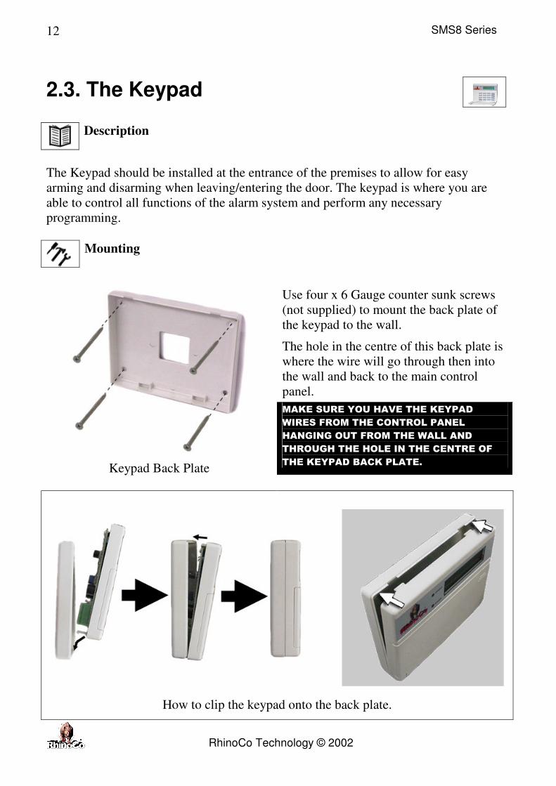
Use four x 6 Gauge counter sunk screws
(not supplied) to mount the back plate of
the keypad to the wall.
The hole in the centre of this back plate is
where the wire will go through then into
the wall and back to the main control
panel.
MAKE SURE YOU HAVE THE KEYPAD
WIRES FROM THE CONTROL PANEL
HANGING OUT FROM THE WALL AND
THROUGH THE HOLE IN THE CENTRE OF
THE KEYPAD BACK PLATE.
Keypad Back Plate
How to clip the keypad onto the back plate.

SMS8 Series
RhinoCo Technology © 2002
13
Wiring
Using 4 core cable preferably:
Connect the terminals on the keypad
to the respective terminal on the
main control panel.
NOTE: A maximum of four
keypads can be connected. If more
than one keypad is connected, the
other keypads have to be addressed.
Use JP1 & JP2 for the addressing of
the keypad.
Keypad Assignment
Jumper OFF
Legend
Jumper ON
If only one keypad is being installed the jumpers do not
need to be moved. If more than one keypad is being
installed then each keypad must be assigned
individually and no additional keypad may set-up the
same way.
WARNING: DO NOT PLACE A JUMPER IN THE JP3 (Jumper 3) POSITION.
Keypad 1
Jumper 1 ON only
Keypad 2
Jumper 2 ON only
Keypad 3
Jumpers 1 & 2 ON only
Keypad 4
No Jumpers installed (default)
JP1 JP2 JP3
JP1 JP2 JP3
JP1 JP2 JP3
JP1 JP2 JP3

SMS8 Series
RhinoCo Technology © 2002
14

SMS8 Series
RhinoCo Technology © 2002
15
2.4. The Outside Siren
Description
The outside siren performs the following important functions:
1. Provides an alarm sound when the system is triggered lets anyone nearby know
that an alarm has occurred].
2. Provides visual deterrent to any would be thieves.
3. Provides visual alert when the alarm has been triggered.
4. A tamper switch protects it so that no thief is able to remove it without the
alarm being triggered.
Mounting
Mount the Outside Siren and Strobe at the front or front side of the building. The
mounting position should be under an eave or out of direct contact with rain or other
water sources. The position should allow line of sight viewing from both the street
(for visual deterrent) and from your main point of entry (for visual confirmation of
arming/disarming - [optional]).
Example: Assemble the Siren Box
Insert the Siren, Tamper Switch and Strobe into the Siren Box.

SMS8 Series
RhinoCo Technology © 2002
16
Example: Siren Box Mounting
1. Drill mounting holes (7mm diameter, 25mm
minimum in depth) into the chosen wall.
2. Use a green star plug. Press each one into the 4
main mounting holes.
3. Make a hole, push the wires through the wall and
up into the ceiling.
4. Screw the top 2 screws half way in.
5. Place the unit to support itself from the top 2
screws through the key shape holes at the top of the
main unit
6. Screw in and tighten the bottom two mounting
screws then tighten the top two screws.

SMS8 Series
RhinoCo Technology © 2002
17
Wiring
Note:
The DC Siren, Strobe, Tamper, Screamer and Outside Siren box are sold separately.
Generally the positive (+) wire from each component such as the strobe and siren is
red in colour or contains a red trace. The negative (-) wire from each component is
generally black or contains a black trace.
General Rule:
RED
BLACK
= Positive
= Negative
(+)
(-)

SMS8 Series
RhinoCo Technology © 2002
18
2.5. The Screamer
Description
Please note: A screamer is not generally supplied with this alarm panel but may be
included with special bundled packages. Screamers are available and sold separately if
one hasn’t been included with your package.
Standard screamer types available include:
Flush mount screamer
Top hat screamer
Mounting
Screamer(s) are generally mounted on the ceiling. It can be located almost anywhere
you like. It is advised that you place it in a position that is central where the sound
travels evenly through the house. Since its main purpose is to make the sound
unbearable to any would be intruder you may choose the most appropriate position to
best suit the building to which it is installed.
Example – mounting a top hat screamer
1. Drill a hole (15mm diameter) into the ceiling where you want to
mount the screamer. This where the wire from the screamer will pass
through. Pick a position where there is no stud/framework above the
ceiling, preferably in a central position such as a corridor or hallway.
2. Feed the wire coming from the screamer up through the 15mm hole
into the ceiling where it will join to the wire going to the control
panel.
3. Push the screamer on to the ceiling aligning the hole with the wire
coming out of the screamer.
4. Place the self-tapping screws into the mounting holes on the screamer

SMS8 Series
RhinoCo Technology © 2002
19
then screw them into the ceiling.
Wiring
The screamer is wired to the BELL and COMM terminals on the control panel in
parallel with the DC Siren.

SMS8 Series
RhinoCo Technology © 2002
20
2.6. The Sensors
Description
Other optional accessories may include:
� Passive Infrared Sensors
� Reed Switches
� Panic buttons
� Smoke sensors
� Other various sensors are also available.
Mounting
Refer to the instructions supplied separately with each sensor you include with or add
to the system.
Wiring
Refer to the instructions supplied separately with each sensor you include with, or add
to the system.
Generally, each zone could contain multiple sensors wired in series but the number of
sensors on each zone should be kept to a minimum.
Each sensor is powered from the two terminals on the control panel labelled as
SWAUX and COMM (these terminals are side by side). Together, these terminals
supply a 12 Volt DC supply to the sensors. No more than 800mA of electrical current
should be drawn from these terminals.
ZONE INPUTS
Connect the sensors to the terminal labelled Zx and C. Where X is a spare available
zone terminal on the panel.

SMS8 Series
RhinoCo Technology © 2002
21
2.7. The Backup Battery
You should only connect the backup battery once the wiring has been completed.
The back up battery should be connect FIRST before connecting the Mains AC
Adaptor.
This panel has been specifically designed to only use a 12 Volt, 7 Ampere hour, [12V
7AH] Sealed Lead-Acid Battery. Connect the red wire from the alarm panel to the
positive terminal of the backup battery and the black wire to the negative terminal of
the backup battery.
2.8. AC Power
Mains power is supplied from a 16VAC, 25 VA plug pack/transformer. Connect the
plug pack or transformer to the terminals labelled AC. The Green (or Green/Yellow)
wire from an Australian plug pack is generally the Earth Wire and should be
connected to the earth point on the panel. The other 2 AC Wires can be connected to
the AC terminals. The AC wires may be placed either way to the AC terminals. They
are not polarity conscious due to the nature of the AC power signal.

SMS8 Series
RhinoCo Technology © 2002
22
3. Operation
3.0. How To ‘Arm’ The System
Before arming the system the system in any mode the keypad must display
“READY”. If it is not ready then it is due to a zone being open or triggered. This may
mean that a window has been left open, a door is still open or there is movement
within the building.
1.
The keypad must display
“Ready” before you are able
to arm the system.
2.
Enter a valid user code
(default is 1234).
3.
Press
Press the “ENTER” key.
4.
During the exit delay the
keypad will display “Exit
now”.
5.
The keypad will display
“Armed” when the system
is fully armed and the
armed light will turn on.
(The strobe will flash for
1.5 seconds)
Ready
Exit now
Armed

SMS8 Series
RhinoCo Technology © 2002
23
3.1. How To ‘Quick Arm’ The System
Use this to arm the system without having to enter a user code.
1.
The keypad must display
“Ready” before you are able
to arm the system.
2.
Press
Press the Q/H Arm button
to arm the system without
having to enter a user code.
3.
During the exit delay the
keypad will display “Exit
now”.
4.
The keypad will display
“Armed”. The strobe will
flash for 1.5 seconds and
the Armed light will turn
on.
Ready
Armed
Exit now

SMS8 Series
RhinoCo Technology © 2002
24
3.2. How To ‘Home Arm’ the System (STAY)
NOTE: If no zones are programmed to be activated when in HOME mode, Home arm is
automatically disabled. This mode is used when protecting your home or office while you are there.
1.
The keypad must display
“Ready” before you are able
to arm the system.
2. Press for 2 seconds
Hold the Q/H Arm button to
home arm the system
without having to enter a
user code.
3.
During the exit delay the
keypad will display “Exit
now”.
4.
The keypad will display
“HomeARM” and the
ARMED light will turn on.
3.3. How To ‘Disarm’ The System
1.
Enter a valid user code
(default is 1234).
2. Press
Press the “ENTER” key
then the system will disarm.
3.
The keypad will display
“Ready”. The strobe light
will flash for 4 seconds and
the armed light will turn off.
Ready
HomeARM
Exit now
Ready

SMS8 Series
RhinoCo Technology © 2002
25
3.4. Phone Operations
3.4.0. How to ‘Arm’ via Mobile Phone (GSM model only)
To Arm the alarm through Phone Operations be sure Phone Remote is enabled
in programming option 4.
Send a text message as shown below to the mobile number assigned to the alarm
system. When the system receives the message it will Arm.
1234A
NOTE: Replace 1234 with your assigned Master
Code.
To receive a confirmation that your system is armed, ensure that Closing reports
are programmed in option 6. The confirmation message will be sent to the SMS
receiver number programmed into the system.
If programmed you will receive a close message to confirm the system is armed. A
closing message will look similar to what is shown below.
1234A
Account No 9991 Close by user 1 End

SMS8 Series
RhinoCo Technology © 2002
26
3.4.1. How to ‘Disarm’ via Mobile Phone (GSM model only)
To Disarm the alarm through Phone Operations be sure Phone Remote is
enabled in programming option 4.
Send a text message as shown below to the mobile number assigned to the alarm
system. When the system receives the message it will Disarm.
1234D
NOTE: Replace 1234 with your assigned Master
Code.
To receive a confirmation that your system is disarmed, ensure that Opening
reports are programmed in option 6. The confirmation message will be sent to
the SMS receiver number programmed into the system.
If programmed you will receive a open message to confirm the system is disarmed. A
opening message will look similar to what is shown below.
1234D
Account No 9991 Open by user 1 End
SMS8 Series
RhinoCo Technology © 2002
27
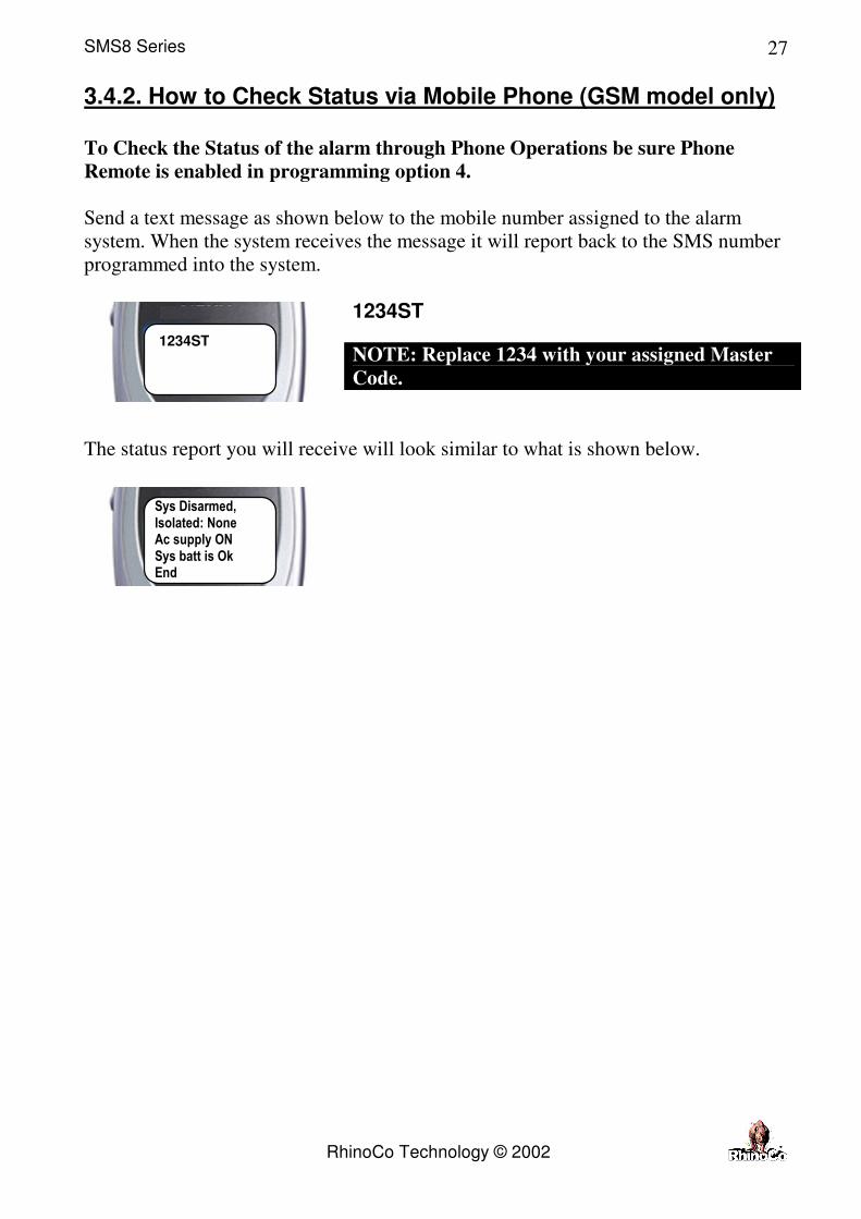
3.4.2. How to Check Status via Mobile Phone (GSM model only) To Check the Status of the alarm through Phone Operations be sure Phone
Remote is enabled in programming option 4.
Send a text message as shown below to the mobile number assigned to the alarm
system. When the system receives the message it will report back to the SMS number
programmed into the system.
1234ST
NOTE: Replace 1234 with your assigned Master
Code.
The status report you will receive will look similar to what is shown below.
1234ST
Sys Disarmed, Isolated: None Ac supply ON Sys batt is Ok End

SMS8 Series
RhinoCo Technology © 2002
28
3.4.3. Phone Messages (SMS)
Some examples of SMS messages that may be sent to you from the alarm system are
as follows:
You will receive this message when your alarm has
been triggered by the back door.
You will receive this message when your alarm has
restored the back door zone.
You will receive this message when your alarm has
been triggered by the Panic button.
You will receive this message when your alarm has
disarmed after a Panic activation.
You will receive this message when your alarm has
lost mains power.
You will receive this message when the alarm has AC
power restored.
Account No 9991 Alarm Back door End
Account No 9991 Ac lost End
Account No 9991 Restr Back door End
Account No 9991 Panic On End
Account No 9991 Panic Off End
Account No 9991 Ac Ok End

SMS8 Series
RhinoCo Technology © 2002
29
3.5. How To Isolate Zones
1.
Ensure the keypad is
displaying “Ready”.
2. Press
Press the Menu Key
3.
The display will show the
following:
(times out in 10 seconds)
4. Press
Press the Enter Key to
select isolate zones.
5.
The display will show the
following.
6.
Enter the master user code
7. Press
Press the Enter Key
8.
The display will show the
following.
Isolate
Isolate Zone Menu=N Enter=Y
Enter Code
Ready

SMS8 Series
RhinoCo Technology © 2002
30
9. Press
(example only)
Press the zone number you
wish to isolate. Pressing
“3” will isolate zone 3.
This is an example only.
10.
The display will show the
following.
11. Press
Press the menu key to
toggle between ‘not
isolate’ and ‘isolate’.
12. Press
Press the Enter key to
move to the next zone and
save any change.
Press the button to
go back one zone.
13. Hold for 2 seconds
Press the cancel button for
2 seconds to exit back to
the ready screen.
NOTE ISOLATED ZONES
Isolated zones will be displayed as shown below from the ready screen.
The display will cycle
through each isolated zone
for 6 seconds before
moving to the next.
Zone NO: 3 Not Isolate
You may change
the isolation setting
for multiple zones.
Ready Bypass: Zone_3 Lounge

SMS8 Series
RhinoCo Technology © 2002
31
3.6. How To Enter ‘Test Mode’
The TEST MENU will allow the installer to perform a WALK TEST of the Zones, a
SIREN & STROBE TEST, DIALLER TEST, and a BATTERY TEST.
1. Press
x 2
Press the Menu Key twice
from the ready screen.
2.
The display will show the
following.
3. Press
Press the Enter key to
select the Test Menu.
3.5.1. Walk Test
4.
Press
Press
Each time a zone is triggered, the zone number
will be displayed for one second and the keypad
will beep.
Zone 4 triggered.
Then, each zone triggered will be displayed for
6 seconds each.
If you press the button it will scroll
forward displaying each zone that has been
triggered up to the most recent zone triggered.
Press to exit this mode.
Test Menu Menu=N Enter=Y
Zone Test Menu=N Enter=Y
Walk Test Zone_4 Lounge

SMS8 Series
RhinoCo Technology © 2002
32
3.5.2. Siren & Strobe Test
5.
Press
Press
This will allow the installer to test the SIREN
and the STROBE. The siren and strobe will
activate for 3 seconds.
If the siren and strobe are not wired you will not
be able to perform this test.
Press repeatedly until the Ready
screen is displayed.
3.5.3. Dial Test
Press
A test message will be sent to the control
room(s) and/or the mobile phone(s) as
programmed.
Make sure that the DIALLER is enabled in the
TIMER / CONTROL (option 4). Also make
sure the correct TELEPHONE NUMBER and
COMMUNICATION FORMAT are selected.
Upon successful completion of the test report the unit will
respond with TEST PASSED. Press to exit the menu.
An SMS message will appear
as shown (if programmed).
DIALLER TEST MUST is enabled for this test to work. (refer
to Installer Programming – Dialler Programming.)
NOTE: If 3 beeps are heard while attempting to complete a dial
test. The DIALLER ENABLED option has not been turned on.
6.
Press
Siren/Stb Menu=N Enter=Y
Dial Test Menu=N Enter=Y
ACC_N0001 Test

SMS8 Series
RhinoCo Technology © 2002
33
3.5.4. Battery Test
Press
The battery test performs a dynamic test of the
battery under load by disconnecting the AC
supply from the charger, this test will take
approximately 2 minutes and upon completion
of the test and depending on the condition of the
battery the unit will respond with TEST
PASSED or TEST FAIL.
7.
Press
to go back to the zone test menu.
OR
Press
Repeatedly to go back to the ready screen.
Press the button to go back to the test menu or press
the button repeatedly to go back to the ready screen.
Batt Test Menu=N Enter=Y
SMS8 Series
RhinoCo Technology © 2002
34
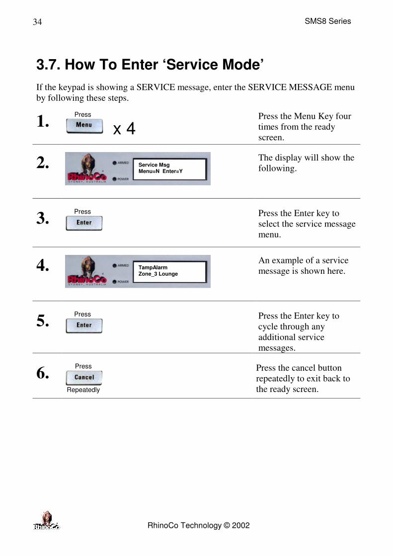
3.7. How To Enter ‘Service Mode’
If the keypad is showing a SERVICE message, enter the SERVICE MESSAGE menu
by following these steps.
1. Press
x 4
Press the Menu Key four
times from the ready
screen.
2.
The display will show the
following.
3. Press
Press the Enter key to
select the service message
menu.
4.
An example of a service
message is shown here.
5. Press
Press the Enter key to
cycle through any
additional service
messages.
6. Press
Repeatedly
Press the cancel button
repeatedly to exit back to
the ready screen.
Service Msg Menu=N Enter=Y
TampAlarm Zone_3 Lounge

SMS8 Series
RhinoCo Technology © 2002
35
3.8. Resetting The Alarm
If a violation of a zone has occurred while the system was armed this will be shown
on the display, follow these steps to clear the memory.
1. Press
x 5
Press the Menu Key five
times from the ready
screen.
2.
The display will show the
following.
3. Press
Press the Enter key. The
memory will be cleared
and the display will return
to the ready screen.
This clears the SERVICE
message as well.
3.9. Telephone Line Faults
In the case of line problems with the telephone system, disconnect the RhinoCo panel
from the line, do not disconnect from the RJ11 jack from the panel as this may
prevent the premise telephones from operating. If the telephone system returns to
normal operation after the removal of the panel from the line, the control panel has a
problem and should be returned for repair.
All faulty equipment, whether under warranty or out must be returned to RhinoCo
Pty. Ltd. or it’s authorized service agents for repairs.
Alarm Reset Menu=N Enter=Y

SMS8 Series
RhinoCo Technology © 2002
36
4. Programming
4.1. General Programming
Throughout programming, 3
common keys are used. MENU,
ENTER and CANCEL keys are used
to navigate through the various
programmable options. Their
functions are outlined below.
This key is used for cycling through either a menu or
options. Pressing this button will display the next menu
or next option.
����
This is for selecting a menu option or saving a selection
or setting.
����
This key is for moving back up a step and will not save
any changes to the current selection. If held down for
approximately 3 seconds it will exit programming
mode.
Where a cursor is displayed, for example when
programming phone numbers, this key will move the
cursor back one position.
Where a cursor is displayed, for example when
programming phone numbers, this key will move the
cursor forward one position.
DEL Where a cursor is displayed, for example when
programming phone numbers, this key will delete the
number above the cursor.

SMS8 Series
RhinoCo Technology © 2002
37
4.1.1. Quick Programming Guide
Programming
End User
Programming
Installer
Programming
User Codes SMS Phone
Number
Option 1
Installer
PIN code
(User
PIN
codes)
Option 2
Zone
Programming
Option 3
Emerge
(Emergency)
Option 4
Control/
Timers
Option 5
Dial
Menu
Option 6
Rpt
Menu
(Reports)
Master
Code
Zone Type Panic Siren Entry delay Account
Number
Zone Rpt Events
User Codes Zone Chime Medical Siren Exit delay Phone 1 Alarm Open
RF Zone Fire Siren Siren Time Phone 2 Restore Close
Zone Restore Dial Offset SMS_ NetPh
125107
Isolation Panic
Siren Type Dial Period Rec1 Form RF Battery Medical
Zone Isolation AC timer
delay
Rec2 Form RF Lost Fire
Home Mode Battery
offset
Routine
Rec
Duress
Zone Response Battery
Period
Dial Test AC Lost
Pulse Count Line Delay
Sys_batt
Zone Name Bell
Reverse
Remote
RF Tamper
Dial Enable
RF Remote
Open
Override

SMS8 Series
RhinoCo Technology © 2002
38
4.2. End User Programming
This area is for the changing of the user PIN numbers and the SMS phone number that
the system will send messages to in the event of the alarm being activated.
4.2.1. How To Enter ‘User Mode’
1.
Ensure the keypad is
displaying “Ready”.
2. Press
x 3
Press the Menu Key three
times from the ready
screen.
3.
The display will show the
following.
4. Press
Press the Enter key to
select program mode.
5.
The display will show the
following.
6. Press
Press the Enter key to
select User mode.
7.
An example of a service
message is shown here.
8.
Enter the valid master
code (default is 1234).
Program Mode Menu=N Enter=Y
User Mode ? Menu=N Enter=Y
Ready
Put MasterID

SMS8 Series
RhinoCo Technology © 2002
39
4.2.1.1. Changing User Codes
9.
Press
This will allow you to change user codes 1 to
16. User 1 is the Master Code.
Enter the new 4 digit code for the displayed user
Press to save the new user code and to
select the next user
Press to go back to the previous user
code. This will not save any changes to the
current user code.
Press repeatedly to exit user
programming until the Ready screen is
displayed.
10. Press
Select User Menu=N Enter=Y
Change User 1 Code:1234

SMS8 Series
RhinoCo Technology © 2002
40
4.2.1.2. Change the SMS Phone Number
11.
Press
This will allow you to change the SMS phone
number.
Enter the new mobile phone number
Press to save the new phone number.
Press to go back to the Program SMS
menu. This will not save any changes to the
SMS phone number.
Press repeatedly to go back and exit
user programming or until the Ready screen is
displayed.
Press
to go back to the select user menu.
OR
Press
Repeatedly to go back to the ready screen.
Program SMS Menu=N Enter=Y
Enter Ph No 0416036583

SMS8 Series
RhinoCo Technology © 2002
41
4.3. Installer Programming
This area is generally used when the system is first installed into the premises or
when changing system components (adding/removing detectors and sensors),
after defaulting the system.
4.3.1. How To Enter ‘Installer Mode’
1.
Ensure the keypad is
displaying “Ready”.
2. Press
x 3
Press the Menu Key
three times from the
ready screen.
3.
The display will show
the following.
4. Press
Press the Enter key to
select program mode.
5.
The display will show
the following.
6. Press
Press the Menu key to
select Install mode.
7.
An example of a service
message is shown here.
Ready
Program Mode Menu=N Enter=Y
User Mode ? Menu=N Enter=Y
Install Mode Menu=N Enter=Y

SMS8 Series
RhinoCo Technology © 2002
42
8. Press
Press the Enter key to
select Install mode.
9.
The display will show
the following.
10.
Enter the Installers code.
Default is 012345.
11.
The display will show
the following.
12. Press for installer code and user code programming OR
Press for zone programming OR
Press for emergency key programming OR
Press for timers control programming OR
Press for dialer programming OR
Press for event report programming.
Enter Code
Enter 1-6

SMS8 Series
RhinoCo Technology © 2002
43
4.3.2. Option 1 - Installer Code and User Code Programming
This menu will enable you to change the installer code, master code and any user code.
The panel can store up to 16 user codes.
Once you enter option 1 from installers mode the display will show the following.
Enter the new 6 digit installer code
Press repeatedly to
exit and disregard any
changes.
Press
Press enter to save the new
installer code.
1.
2. Press
4.3.2.1. Changing The Master Code
Enter the new 4 digit Master Code.
Press repeatedly to
exit and disregard any
changes.
Press
Press enter to save the new
installer code.
3.
4. Press
Install PIN CODE:012345
Master PIN CODE:1234

SMS8 Series
RhinoCo Technology © 2002
44
4.3.2.2. Changing User Codes
Select a user 2 – 16.
Press repeatedly to
exit and disregard any
changes.
The display will show the
following (example only).
Enter the new 4 digit code for the displayed user
Press to save the new user code and to select the next
user
Press to go back to the previous user code. This will
not save any changes to the current user code.
Press repeatedly to exit user programming.
5.
Press
to go back to the Installer PIN menu.
OR
Press
Repeatedly to go back to the ready screen.
Select User
User No: 2 CODE: 5234
SMS8 Series
RhinoCo Technology © 2002
45
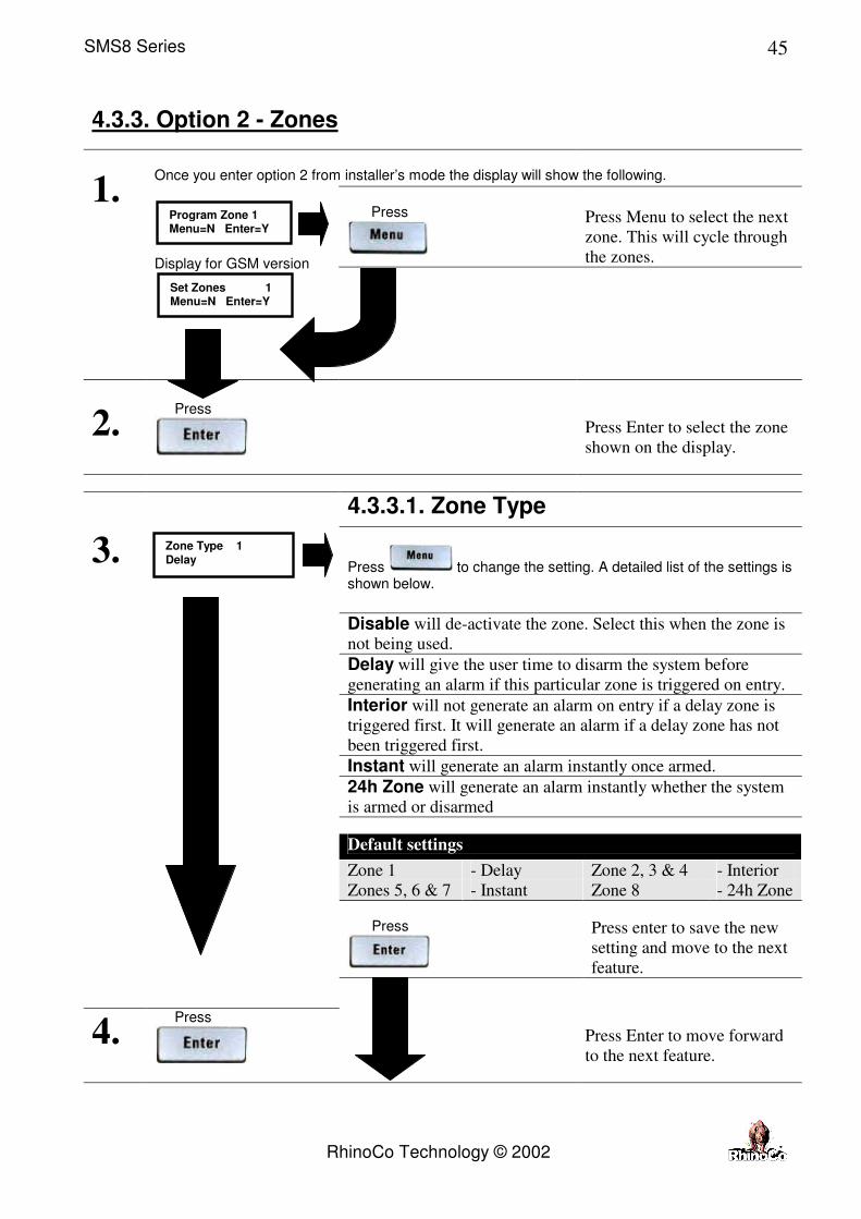
4.3.3. Option 2 - Zones
Once you enter option 2 from installer’s mode the display will show the following.
Press
Press Menu to select the next
zone. This will cycle through
the zones.
1.
Display for GSM version
2. Press
Press Enter to select the zone
shown on the display.
4.3.3.1. Zone Type
Press to change the setting. A detailed list of the settings is shown below.
Disable will de-activate the zone. Select this when the zone is
not being used. Delay will give the user time to disarm the system before
generating an alarm if this particular zone is triggered on entry. Interior will not generate an alarm on entry if a delay zone is
triggered first. It will generate an alarm if a delay zone has not
been triggered first.
Instant will generate an alarm instantly once armed.
24h Zone will generate an alarm instantly whether the system
is armed or disarmed
Default settings
Zone 1 - Delay Zone 2, 3 & 4 - Interior Zones 5, 6 & 7 - Instant Zone 8 - 24h Zone
Press
Press enter to save the new
setting and move to the next
feature.
3.
4. Press
Press Enter to move forward
to the next feature.
Program Zone 1 Menu=N Enter=Y
Zone Type 1 Delay
Set Zones 1 Menu=N Enter=Y

SMS8 Series
RhinoCo Technology © 2002
46
4.3.3.2. Chime
Press to change the setting. A detailed list of the settings is shown below.
No will disable chime.
Yes will sound the keypad buzzer when a zone is triggered
when the system is in the disarmed state.
Press
Press enter to save the
setting and move forward to
the next feature.
5.
6. Press
Press Enter to move forward
to the next feature.
4.3.3.3. RF Zone
Press to change the setting. A detailed list of the settings is shown below.
No will disable the zone from being used as a wireless
zone. Yes : For use with the RhinoCo Wireless receiver and
sensors. Product Code: SMS8RX, PIRW & WREED
etc. NOTE: This mode should be set to disabled if
none of these devices are being used.
Press
Press enter to save the
setting and move forward to
the next feature.
7.
8. Press
Press Enter to move forward
to the next feature.
Chime 1 No
RF_Zone 1 No

SMS8 Series
RhinoCo Technology © 2002
47
4.3.3.4 Zone Restore
Press to change the setting. A detailed list of the settings is shown below.
On Disarm Once the time out period has finished, that zone
cannot be re-triggered until the alarm is
disarmed and then re-armed. On Seal means the zone will restore as soon as the time
out (siren) period is finished. It can then be re-
triggered
Press
Press enter to save the
setting and move forward to
the next feature.
9.
10. Press
Press Enter to move forward
to the next feature.
4.3.3.5 Siren Type
Press to change the setting. A detailed list of the settings is shown below.
Disable :
The siren will not sound for the chosen zone.
Steady means the siren will constantly sound when
the chosen zone is triggered. Pulsing means the siren will turn on then off every
second. Just Keypad
means the keypad buzzer will sound only.
Press
Press enter to save the
setting and move forward to
the next feature.
11.
12. Press
Press Enter to move forward
to the next feature.
Zn Restore 1 On Disarm
Siren Type 1 Steady

SMS8 Series
RhinoCo Technology © 2002
48
4.3.3.6. Zone Isolation
Press to change the setting. A detailed list of the settings is shown below.
No
will disable the zone from being isolated.
Yes will enable the zone to be isolated.
Press
Press enter to save the
setting and move forward
to the next feature.
13.
12. Press
Press Enter to move
forward to the next feature.
4.3.3.7. Home Mode
Press to change the setting. A detailed list of the settings is shown below.
No
will enable the zone to activate in home mode.
Yes will disable the zone in home mode.
Press
Press enter to save the
setting and move forward
to the next feature.
14.
15. Press
Press Enter to move
forward to the next feature.
Isolation 1 Yes
Home mode 1 No

SMS8 Series
RhinoCo Technology © 2002
49
4.3.3.8. Zone Response Time
Press to change the setting. A detailed list of the settings is shown below.
20 Msec The zone must be open for 20 milli-seconds
before it will be trigger and register as an alarm.
250 Msec The zone must be open for 250 milli-seconds
before it will be trigger and register as an alarm.
500 Msec The zone must be open for 500 milli-seconds
before it will be trigger and register as an alarm.
This setting suits most sensors.
Press
Press enter to save the
setting and move forward to
the next feature.
16.
17. Press
Press Enter to move forward
to the next feature.
4.3.3.9. Pulse Count
Press to change the setting. A detailed list of the settings is shown below.
No Will enable the zone to trigger the alarm after the zone
opens once. Yes Will only allow an alarm trigger after it has opened the
zone twice.
Press
Press enter to save the
setting and move forward to
the next feature.
18.
19. Press
Press Enter to move forward
to the next feature.
Response 1 500 Msec
Double Hit 1 No

SMS8 Series
RhinoCo Technology © 2002
50
4.3.3.10. Zone Name
Press to change the setting. A detailed list of the settings is shown below.
The name that you choose for the particular zone will be shown
on the keypad and on SMS messages.
None M_Bedroom Reception Show Room
FrontDoor Bedroom 2 Office 1 Hallway BackDoor Bedroom 3 Office 2 Panic Kitchen Fire Office 3 Tamper Lounge Garage Workshop
Dining Basement StoreRoom
Press
Press enter to save the
setting and move to the first
feature on the next zone.
20.
21.
Press
to go back to first feature of the next zone.
OR
Press
Repeatedly to go back to the ready screen.
Zone Name 1 None

SMS8 Series
RhinoCo Technology © 2002
51
4.3.4. Option 3 - Emergency Keys
Once you enter option 3 from installers mode the display will show the following.
Press
Press Menu to move to the
Timer & Control options or
press repeatedly to
exit back to the ready screen.
1.
2. Press
Press Enter to select the
Emergency options.
4.3.4.1. Panic Siren
Press
Press Enter to select the
panic option
The display will show the
following.
Press
to select one of the options below.
Press to keep the
current setting or press
repeatedly to exit
back to the previous menu.
Disable Disables panic from triggering the siren.
Steady Enables the siren to sound steady when panic
is triggered.
Pulsing Enables the siren to turn on then back off
every second when panic is triggered.
Just Keypad Enables only the keypad to buzz when panic
is triggered.
Press
Press Enter to save your
choice and move to the next
menu.
3.
4. Press
Press Enter to move
forward to the next feature.
Emerg Menu=N Enter=Y
Panic Menu=N Enter=Y
Siren Type Steady

SMS8 Series
RhinoCo Technology © 2002
52
4.3.4.2. Medical Siren
Press
Press Enter to select the
panic option
The display will show the
following.
Press
to select one of the options below.
Press to keep the
current setting or press
repeatedly to exit
back to the previous menu.
Disable Disables panic from triggering the siren.
Steady Enables the siren to sound steady when panic
is triggered.
Pulsing Enables the siren to turn on then back off
every second when panic is triggered.
Just Keypad Enables only the keypad to buzz when panic
is triggered.
Press
Press Enter to save your
choice and move to the next
menu.
5.
6. Press
Press Enter to move
forward to the next feature.
Medic Menu=N Enter=Y
Siren Type Pulsing

SMS8 Series
RhinoCo Technology © 2002
53
4.3.4.3. Fire Siren
Press
Press Enter to select the
panic option
The display will show the
following.
Press
to select one of the options below.
Press to keep the
current setting or press
repeatedly to exit
back to the previous menu.
Disable Disables panic from triggering the siren.
Steady Enables the siren to sound steady when panic
is triggered.
Pulsing Enables the siren to turn on then back off
every second when panic is triggered.
Just Keypad Enables only the keypad to buzz when panic
is triggered.
Press
Press Enter to save your
choice and move to the next
menu.
7.
8. Press
to go to the next menu.
Press
Repeatedly to go back to the
ready screen.
Fire Menu=N Enter=Y
Siren Type Pulsing

SMS8 Series
RhinoCo Technology © 2002
54
4.3.5. Option 4 - Timers / Control
Once you enter option 4 from installers mode or from the previous menu the display will show the following.
Press
Press Menu to select the next
menu or press
repeatedly to exit back to the
ready screen.
1.
2. Press
Press Enter to select the
Cntrl/Timers menu.
4.3.5.1. Entry Delay
Press to change the Entry Delay setting. A detailed list of the settings is shown below. The times are in seconds
This feature determines the amount of time the user has to enter
and disarm the system before an alarm is generated.
5 s 30 s 75 s 10 s 45 s 90 s
20 s 60 s
Press
Press enter to save the new
setting and move to the next
feature.
3.
4. Press
Press Enter to move forward
to the next feature.
Cntrl/Timers Menu=N Enter=Y
Entry Delay 10 s

SMS8 Series
RhinoCo Technology © 2002
55
4.3.5.2. Exit Delay
Press to change the Exit Delay setting. A detailed list of the settings is shown below. The times are in seconds
This feature determines the amount of time that the user(s) has
to exit the premises.
5 s 30 s 75 s 10 s 45 s 90 s
20 s 60 s
Press
Press enter to save the new
setting and move to the next
feature.
3.
4. Press
Press Enter to move forward
to the next feature.
4.3.5.3. Siren Time
Press to change the Siren Time setting. A detailed list of the settings is shown below. The times are in minutes.
This is the duration that the siren will be on for when in alarm.
2 m 5 m 7 m 10 m
Press
Press enter to save the new
setting and move to the next
feature.
5.
6. Press
Press Enter to move forward
to the next feature.
Exit Delay 10 s
Siren Time 2 m

SMS8 Series
RhinoCo Technology © 2002
56
4.3.5.4. Dial Offset
Press to change the Dialer Offset setting. A detailed list of the settings is shown below. The times are in hours.
This feature allows the user to select what time of the day the
panel will perform a dialer test. The dial test will be performed
after the chosen amount of hours once you exit programming
mode.
(eg. If you choose 2h then the dialer test will be performed 2
hours after you exit programming mode)
0 1 h 2 h … 22 h 23 h (increments up by 1 hour)
Press
Press enter to save the new
setting and move to the next
feature.
5.
6. Press
Press Enter to move forward
to the next feature.
4.3.5.5. Dial Period
Press to change the Dial Period setting. A detailed list of the settings is shown below.
This feature allows the user to select what the time between test
reports.
24 h 24 hours between test reports.
7d 7 days between test reports.
30 d 30 days between test reports.
Press
Press enter to save the new
setting and move to the next
feature.
7.
8. Press
Press Enter to move forward
to the next feature.
Dial Offset 0
Dial Period 24 h

SMS8 Series
RhinoCo Technology © 2002
57
4.3.5.6. AC Timer Delay
Press to change the AC Timer Delay setting. A detailed list of the settings is shown below. The times are in minutes.
This is the maximum time allowed for the AC power to be off
from the panel before the AC FAIL message is generated if
programmed.
15 m 30 m 45 m 60 m
Press
Press enter to save the new
setting and move to the next
feature.
9.
10. Press
Press Enter to move forward
to the next feature.
4.3.5.7. Battery Offset
Press to change the Battery Offset setting. A detailed list of the settings is shown below. The times are in hours.
This feature allows the user to select what time of the day the
panel will perform a battery test. This will be performed, the
chosen number of hours after you exit programming mode.
(eg. If you choose 2h then the battery test will be performed 2
hours after you exit programming mode)
This will also assign what time of the day the panel will dial out
if it is programmed in option 6: Program Event Reports.
0 1 h 2 h … 22 h 23 h (increments up by 1 hour)
Press
Press enter to save the new
setting and move to the next
feature.
11.
12. Press
Press Enter to move forward
to the next feature.
Ac Timer Delay 15 m
Batt Offset 0

SMS8 Series
RhinoCo Technology © 2002
58
4.3.5.8. Battery Period
Press to change the Battery Offset setting. A detailed list of the settings is shown below.
Description
24 h Sends a message every 24 hours if the battery is flat.
7 d Sends a message every 7 days if the battery is flat.
30 d Sends a message every 30 days if the battery is flat.
Press
Press enter to save the new
setting and move to the next
feature.
13.
14. Press
Press Enter to move forward
to the next feature.
Batt Period 24 h

SMS8 Series
RhinoCo Technology © 2002
59
4.3.5.9. Line Delay
Press to change the Line Delay setting. A detailed list of the settings is shown below.
This is the maximum time allowed for the Telephone line to be
disconnected from the panel or for the wrong line voltage being
detected before the LINE DELAY message is generated and
sent via SMS message to the programmed number.
Disabl Does not send any message for telephone line faults.
15min Sends a message if the phone line is not working for
more than 15 minutes.
30min Sends a message if the phone line is not working for
more than 30 minutes.
45min Sends a message if the phone line is not working for
more than 45 minutes.
Press
Press enter to save the new
setting and move to the next
feature.
15.
16. Press
Press Enter to move forward
to the next feature.
Line Delay Disable

SMS8 Series
RhinoCo Technology © 2002
60
4.3.5.10. Bell Reverse
Press to change the Bell Reverse setting. A detailed list of the settings is shown below.
Bell Reverse will enable the BELL output to rest at +12V and
go open circuit when triggered.
No Does not send any message for telephone line faults.
Yes Sends a message if the phone line is not working for
more than 15 minutes.
Press
Press enter to save the new
setting and move to the next
feature.
17.
18. Press
Press Enter to move forward
to the next feature.
4.3.5.11. RF Tamper
Press to change the RF Tamper setting. A detailed list of the settings is shown below.
(RF version only)
This is to enable the tamper switch on the RHINOCO Wireless
devices to set the alarm off whether the system is in the arm or
disarm state.
No This will disable tamper on wireless detectors
connected through an SMS8RX receiver.
Yes This will enable tamper on wireless detectors
connected through an SMS8RX receiver.
Press
Press enter to save the new
setting and move to the next
feature.
19.
20. Press
Press Enter to move forward
to the next feature.
Bell Reverse No
RF Tamper No
SMS8 Series
RhinoCo Technology © 2002
61
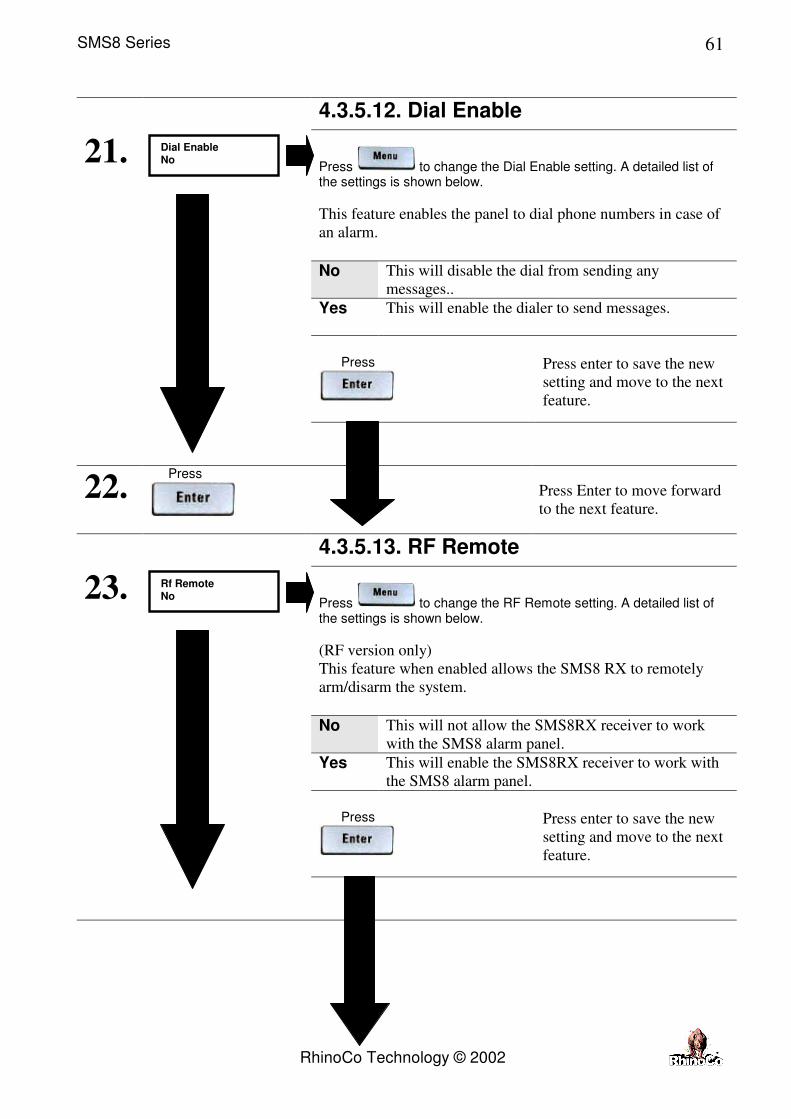
4.3.5.12. Dial Enable
Press to change the Dial Enable setting. A detailed list of the settings is shown below.
This feature enables the panel to dial phone numbers in case of
an alarm.
No This will disable the dial from sending any
messages..
Yes This will enable the dialer to send messages.
Press
Press enter to save the new
setting and move to the next
feature.
21.
22. Press
Press Enter to move forward
to the next feature.
4.3.5.13. RF Remote
Press to change the RF Remote setting. A detailed list of the settings is shown below.
(RF version only)
This feature when enabled allows the SMS8 RX to remotely
arm/disarm the system.
No This will not allow the SMS8RX receiver to work
with the SMS8 alarm panel.
Yes This will enable the SMS8RX receiver to work with
the SMS8 alarm panel.
Press
Press enter to save the new
setting and move to the next
feature.
23.
Dial Enable No
Rf Remote No
SMS8 Series
RhinoCo Technology © 2002
62
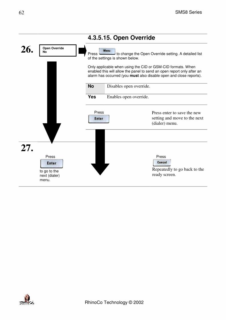
4.3.5.15. Open Override
Press to change the Open Override setting. A detailed list of the settings is shown below. Only applicable when using the CID or GSM-CID formats. When enabled this will allow the panel to send an open report only after an alarm has occurred (you must also disable open and close reports).
No Disables open override.
Yes Enables open override.
Press
Press enter to save the new
setting and move to the next
(dialer) menu.
26.
27. Press
to go to the next (dialer) menu.
Press
Repeatedly to go back to the
ready screen.
Open Override No

SMS8 Series
RhinoCo Technology © 2002
63
4.3.6. Option 5. Dialer
Once you enter option 5 from installers mode or from the previous menu the display will show the following.
Press
Press Menu to select the next
(Event Report) menu or press
repeatedly to exit
back to the ready screen.
1.
2. Press
Press Enter to select the
Cntrl/Timers menu.
4.3.6.1. Account Number
Enter the new 6 digit account number.
If you have a 4 digit account number then use two leading zero’s eg. 003234
Press repeatedly to
exit and disregard any
changes.
This number is sent on SMS messages and used as an
identification if multiple panels are reporting back to one
number. If using back to base monitoring this number must be
allocated by the monitoring company or control room. Press
Press enter to save the new
account number.
3.
4. Press
Dial Menu Menu=N Enter=Y
Account 000001

SMS8 Series
RhinoCo Technology © 2002
64
4.3.6.2. Phone Number 1
Enter the new phone number for Phone 1.
Press repeatedly to
exit and disregard any
changes.
This number is sent on SMS messages and used as
identification if multiple panels are reporting back to one
number. If using back to base monitoring this number must be
allocated by the monitoring company or control room.
Press to move the cursor back one space.
Press to move the cursor forward one space.
Press to delete the digit on the cursor.
Press
Press enter to save the new
number for Phone 1.
5.
6. Press
Phone1 01234567

SMS8 Series
RhinoCo Technology © 2002
65
4.3.6.3. Phone Number 2
Enter the new phone number for Phone 2.
Press repeatedly to
exit and disregard any
changes.
This number is sent on SMS messages and used as
identification if multiple panels are reporting back to one
number. If using back to base monitoring this number must be
allocated by the monitoring company or control room.
Press to move the cursor back one space.
Press to move the cursor forward one space.
Press to delete the digit on the cursor.
Press
Press enter to save the new
number for Phone 2.
7.
8. Press
Phone2 01234567

SMS8 Series
RhinoCo Technology © 2002
66
4.3.6.4. SMS Network Phone Number
Enter the new phone number for the SMS Network.
Press repeatedly
to exit and disregard any
changes.
CAUTION! You should leave this number 125 107 – The
018018767 number is being phased out. Do not change this to
any other number if the panel is being used in Australia.
Press to move the cursor back one space.
Press to move the cursor forward one space.
Press to delete the digit on the cursor.
Press
Press enter to save the new
number for the SMS
Network.
9.
10. Press
SMS_NetPh 125107

SMS8 Series
RhinoCo Technology © 2002
67
4.3.6.5. Receiver 1 Format Type
Press to change the format of Receiver 1 / Phone1. A detailed list of the settings is shown below.
CID Contact ID for Back To Base monitoring
via fixed line. SMS Short Message Services for text messages to
your mobile phone via fixed line.
Press
Press enter to save the new
setting and move to the
next feature.
11.
12. Press
Press Enter to move
forward to the next feature.
Rec1 Form CID

SMS8 Series
RhinoCo Technology © 2002
68
4.3.6.6. Receiver 2 Format Type
Press to change the format of Receiver 2 / Phone2. A detailed list of the settings is shown below.
CID Contact ID for Back To Base monitoring.
SMS Short Message Services for text messages to
your mobile phone.
GSM Not in use
Press
Press enter to save the new
setting and move to the
next feature.
13.
14. Press
Press Enter to move forward
to the next feature.
Rec2 Form CID
SMS8 Series
RhinoCo Technology © 2002
69
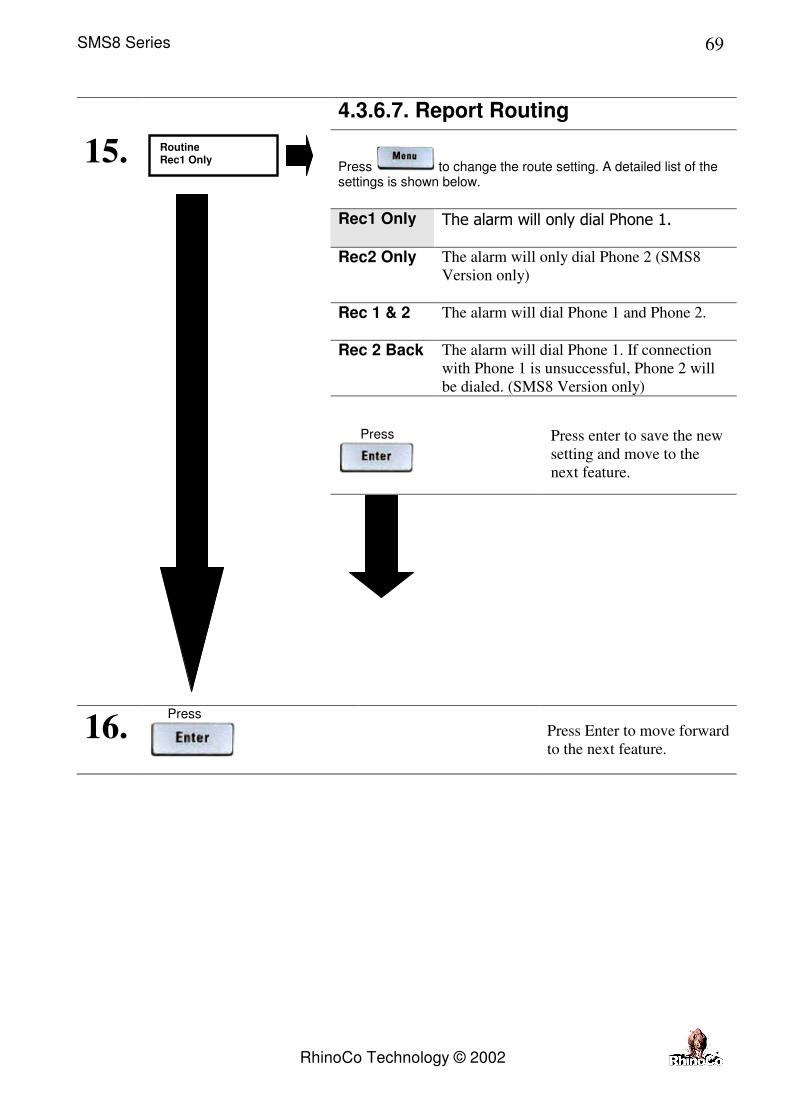
4.3.6.7. Report Routing
Press to change the route setting. A detailed list of the settings is shown below.
Rec1 Only The alarm will only dial Phone 1.
Rec2 Only The alarm will only dial Phone 2 (SMS8
Version only)
Rec 1 & 2 The alarm will dial Phone 1 and Phone 2.
Rec 2 Back The alarm will dial Phone 1. If connection
with Phone 1 is unsuccessful, Phone 2 will
be dialed. (SMS8 Version only)
Press
Press enter to save the new
setting and move to the
next feature.
15.
16. Press
Press Enter to move forward
to the next feature.
Routine Rec1 Only

SMS8 Series
RhinoCo Technology © 2002
70
4.3.6.8. Dialer Test Reports
Press to change the dialer test setting. A detailed list of the settings is shown below.
Yes This will enable automatic dialer test reports.
Not This will disable automatic dialer test reports.
Press
Press enter to save the new setting
and move to the next (Event
Reports) menu.
17.
18. Press
to go to the next (Event Report) menu.
Press
Repeatedly to go back to the ready
screen.
Dial Test Yes

SMS8 Series
RhinoCo Technology © 2002
71
4.3.7. Option 6. Event Reports
Once you enter option 6 from installers mode or from the previous menu the display will show the following.
Press
to go back to the installer options
1.
2. Press
Press Enter to select the
Report menu.
4.3.7.1. Zone Reports Press
to skip to the next (Events) menu.
Press Menu to skip to the
next Events menu.
3.
4. Press
Press Enter to select the
Report menu.
Rpt Menu Menu=N Enter=Y
Zone Rpt Menu=N Enter=Y

SMS8 Series
RhinoCo Technology © 2002
72
4.3.7.1.1. Alarm Reporting
Press to change the Alarm Reporting setting. A detailed list of the settings is shown below.
Note the zone number on the top right hand side of the display. After pressing Enter repeatedly to scroll through the first set of features the same features will be displayed for the next zone.
Yes Will enable the dialer when an alarm event occurs.
No Will disable the dialer when an alarm event occurs.
Press
Press enter to save the new
setting and move to the next
feature.
5.
6. Press
Press Enter to move forward
to the next feature.
4.3.7.1.2. Restore Reporting
Press to change the Restore Reporting setting. A detailed list of the settings is shown below.
Yes Will enable the dialer when a restore event occurs.
No Will disable the dialer when a restore event occurs.
Press
Press enter to save the new
setting and move to the next
feature.
7.
8. Press
Press Enter to move forward
to the next feature.
Alarm 1 Yes
Restore 1 Yes

SMS8 Series
RhinoCo Technology © 2002
73
4.3.7.1.3. Isolation Reporting
Press to change the Isolation Reporting setting. A detailed list of the settings is shown below.
Yes Will enable the dialer when an isolation event occurs.
No Will disable the dialer when an isolation event occurs.
Press
Press enter to save the new
setting and move to the next
feature.
9.
10. Press
Press Enter to move forward
to the next feature.
4.3.7.1.4. RF Battery Reporting
Press to change the RF Battery Reporting setting. A detailed list of the settings is shown below.
An RF Battery event occurs when the battery on one of the
wireless detectors has a low battery. This is only compatible
with the SMS8RX receiver.
Yes Will enable the dialer when a RF low battery event
occurs.
No Will disable the dialer when a RF low battery event
occurs.
Press
Press enter to save the new
setting and move to the next
feature.
11.
12. Press
Press Enter to move forward
to the next feature.
Isolate 1 Yes
RF batt 1 No

SMS8 Series
RhinoCo Technology © 2002
74
4.3.7.1.5. RF Loss Reporting
Press to change the RF Loss Reporting setting. A detailed list of the settings is shown below.
An RF Loss event occurs when one or more of the Wireless
sensors has been missing from the system for more than 24
hours. This is only compatible with the SMS8RX receiver and
compatible sensors.
Yes Will enable the dialer when a RF loss event occurs.
No Will disable the dialer when a RF loss event occurs.
Press
Press enter to save the new
setting and move to the same
set of features for the next
zone.
13.
14. Press
to move to the same set of features above for the next zone (up to zone 8). Note: Zone number on top right side of the display.
Press repeatedly to
exit back to the ready screen.
15. Press
to move forward to the Events Menu.
Press Enter to move forward
to the next (Events) menu.
Press repeatedly to
exit back to the ready screen.
RF lost 1 No
RF lost No
8

SMS8 Series
RhinoCo Technology © 2002
75
4.3.7.2. Events Menu Press
to go back to the Zone Report menu.
Press repeatedly to
exit back to the ready screen.
1.
2. Press
Press Enter to select the
Report menu.
4.3.7.2.1. Open Reporting
Press to change the Open Reporting setting. A detailed list of the settings is shown below.
Yes Will enable the dialer when an open or disarming
event occurs.
No Will disable the dialer when an open or disarming
event occurs.
Press
Press enter to save the new
setting and move to the next
feature.
3.
4. Press
Press Enter to move forward
to the next feature.
Events Menu=N Enter=Y
Open Yes

SMS8 Series
RhinoCo Technology © 2002
76
4.3.7.2.2. Close Reporting
Press to change the Close Reporting setting. A detailed list of the settings is shown below.
Yes Will enable the dialer when an close or arming event
occurs.
No Will disable the dialer when an open or arming event
occurs.
Press
Press enter to save the new
setting and move to the next
feature.
5.
6. Press
Press Enter to move forward
to the next feature.
4.3.7.2.3. Panic Reporting
Press to change the Panic Reporting setting. A detailed list of the settings is shown below.
This refers to the key if held for 2 seconds on your
keypad.
Yes Will enable the dialer when a panic event occurs.
No Will disable the dialer when a panic event occurs.
Press
Press enter to save the new
setting and move to the next
feature.
7.
8. Press
Press Enter to move forward
to the next feature.
Close Yes
Panic Yes

SMS8 Series
RhinoCo Technology © 2002
77
4.3.7.2.4. Medical Reporting
Press to change the Medical Reporting setting. A detailed list of the settings is shown below.
This refers to the key if held for 2 seconds on your
keypad.
Yes Will enable the dialer when a medical event occurs.
No Will disable the dialer when a medical event occurs.
Press
Press enter to save the new
setting and move to the next
feature.
9.
10. Press
Press Enter to move forward
to the next feature.
4.3.7.2.5. Fire Reporting
Press to change the Fire Reporting setting. A detailed list of the settings is shown below.
This refers to the key if held for 2 seconds on your
keypad.
Yes Will enable the dialer when a Fire event occurs.
No Will disable the dialer when a Fire event occurs.
Press
Press enter to save the new
setting and move to the next
feature.
11.
12. Press
Press Enter to move forward
to the next feature.
Medic No
Fire No

SMS8 Series
RhinoCo Technology © 2002
78
4.3.7.2.6. Duress Reporting
Press to change the Duress Reporting setting. A detailed list of the settings is shown below.
A Duress is triggered by the User code 8 being entered.
Yes Will enable the dialer when a Duress event occurs.
No Will disable the dialer when a Duress event occurs.
Press
Press enter to save the new
setting and move to the next
feature.
13.
14. Press
Press Enter to move forward
to the next feature.
4.3.7.2.7. AC Loss Reporting
Press to change the AC loss Reporting setting. A detailed list of the settings is shown below.
“AC OK” will be sent as soon as the AC Power is reconnected
to the system. “AC LOSS” will be sent as soon as AC Power is
removed from the system and the AC timer is up.
Yes Will enable the dialer when an AC loss event occurs.
No Will disable the dialer when an AC loss event occurs.
Press
Press enter to save the new
setting and move to the next
feature.
15.
16. Press
Press Enter to move forward
to the next feature.
Duress No
AC lost Yes

SMS8 Series
RhinoCo Technology © 2002
79
4.3.7.2.8. Low Backup Battery Reporting
Press to change the Low Backup Battery Reporting setting. A detailed list of the settings is shown below.
Will enable the dialer to send low battery notification messages
when the back up battery is low.
Yes Will enable the dialer when a Low Backup Battery
has been detected.
No Will disable the dialer when a Low Backup Battery
has been detected.
Press
Press enter to save the new
setting and move to the next
feature.
17.
18. Press
Press Enter to move forward
to the next feature.
4.3.7.2.9. Receiver Supervision Reporting
Press to change the Receiver Supervision Reporting setting. A detailed list of the settings is shown below.
Yes Will enable the dialer when the panel detects that the
SMS8RX receiver is not communicating with the
panel.
No Will disable the dialer when the panel detects that the
SMS8RX receiver is not communicating with the
panel.
Press
Press enter to save the new
setting and go back to the
installers option menu.
19.
20. Press
to go back to the installers option menu
Press Enter to go back to the
installers option menu or
press repeatedly to
exit back to the ready screen.
21.
Installers option menu.
Sys_batt Yes
Remote No
Enter 1-6

SMS8 Series
RhinoCo Technology © 2002
80
4.4. Defaulting The System
1. Remove all power from the SMS8 panel.
2. Place a short on the default pads on the main board.
3. Power up the panel by either connecting the AC plugpack or the backup battery.
4. Remove the short on the two default pads.
5. The panel is now defaulted and the shaded values in the section Installers Programming now
apply.
Defaulting Pads

SMS8 Series
RhinoCo Technology © 2002
81
5. Warranty
5.1. Warning Limitations & Warranty While this system is an advanced security system, it does not offer guaranteed protection against
burglary or any other emergency. Any alarm system, whether commercial or residential, is subject to
compromise or failure to warn for a variety of reasons. For example:
• Intruders may gain access through unprotected openings, or have the technical sophistication to
bypass an alarm or disconnect an alarm warning device.
• Intrusion detectors (e.g., microwave detectors), and many other sensing devices will not work
without power. Battery operated devices will not work without batteries, with dead batteries or if
the batteries are not put in properly. Devices powered solely by AC will not work if their AC
power supply is cut off for any reason, however briefly.
• Signals sent by wireless transmitters may be blocked or reflected by metal before they reach the
alarm receiver. Even if the signal path has been recently checked during a weekly test, blockage
can occur if a metal object is moved into the path.
• Microwave Detectors can only detect intrusion within the designed ranges as set out in their
installation manual.
• Alarm warning devices such as sirens, bells or horns may not alert people or wake up sleepers
who are located on the other side of closed or partly open doors. Even persons who are awake
may not hear the warning if the alarm is muffled by noise from a stereo, radio, air conditioner or
other appliances, or by passing traffic. Finally, alarm warning devices, however loud, may not
warn hearing-impaired people or waken deep sleepers.
• This equipment, like other electrical devices, is subject to component failure. Even though this
equipment is designed to last as long as 10 years, the electronic components could fail at any
time.
• The most common cause of an alarm system not functioning when an intrusion occurs is
inadequate maintenance. This alarm system should be tested weekly to make sure all devices are
working properly.
• Installing an alarm system may make one eligible for lower insurance rates, but an alarm system
is not a substitute for insurance. Owners should continue to act prudently in protecting
themselves and continue to insure their property.
We continue to develop new and improved protection devices. Users of alarm systems owe it to
themselves and their loved ones to learn about these developments.

SMS8 Series
RhinoCo Technology © 2002
82
LIMITED WARRANTY
Cornick Pty Ltd (ABN 74 001 621 610) (Seller), warrants its products to be in conformance with its own plans and specifications and to be free from defects in materials and workmanship under normal use and service for twelve months from the date of original purchase. Sellers obligation shall be limited to repairing or replacing, at its option, free of charge for materials or labor, any part which is proved not in compliance with Sellers specifications or proves defective in materials or workmanship under normal use and service. Seller shall have no obligation under this Limited Warranty or otherwise if the product is altered or improperly repaired or serviced by anyone other than Seller. For warranty service, return transportation prepaid, to 9 Hannabus Place McGraths Hill NSW 2756. Seller has no obligation to attend the buyer’s location to retrieve the goods or make repairs onsite. There are no warranties, expressed or implied, of merchant ability, or fitness for a particular purpose or otherwise, which extend beyond the description on the face hereof. In no case shall seller be liable to anyone for any consequential or incidental damages for breach of this or any other warranty, express or implied, or upon any other basis of liability whatsoever, even the loss or damage is caused by its own negligence or fault. Seller does not represent that the products it sells may not be compromised or circumvented; that the products will prevent any personal injury or property loss by burglary, robbery, fire or otherwise; or that the products will in all cases provide adequate warning or protection. Customer understands that a properly installed and maintained alarm system may only reduce the risk of a burglary, robbery, or fire without warning, but it is not insurance or a guarantee that such will not occur or that there will be no personal injury or property loss as a result. Consequently, seller shall have no liability for any personal injury; property damage or other loss based on a claim the product failed to give any warning. However, if seller is held liable, whether directly or indirectly, for any loss or damage arising under this limited warranty or otherwise, regard less of cause or origin, seller's maximum liability shall not in any case exceed the purchase price of the product, which shall be the complete and exclusive remedy against seller. This warranty replaces any previous warranties and is the only warranty made by Seller on this product. No increase or alteration, written or verbal, of the obligations of this Limited Warranty is authorised.
NOTE: In addition to the warranty conditions, warranty will not be given where a
product has been immersed in water under any circumstances, or where damage has
been caused by hosing the unit, without all due care taken by the owner to protect the
unit by covering with some sort of plastic sheeting.

SMS8 Series
RhinoCo Technology © 2002
83
This page intentionally blank.