Embed Size (px)
Citation preview
SMT - 131
Manual
Ver 2.6
1/6/18
Page 2
Revision History Version 1 Original Document Version 1.1 Added Mode select in Modbus Version 2.0 Based on version 2 Hardware (Firmware 3.0+) Version 2.1 Added temperature calibration, DI logic and High fan limit. Version 2.2 Added default daily start temperature (Firmware 3.03+). Version 2.3 Corrected manual for register 40022 &40023. Added service O/ride on/off Version 2.4 Added enhancements found in version 3.03 Firmware Version 2.5 Added Fan Relay lock to 0-10 outputs function. Firmware Version 40.2+. Version 2.6 Added Sensor Speed response & Sensor Calibration Firmware 40.4+
Index
Index 2
Introduction 3
Thermostat operation 3
Installation - HVAC Control 4
DIP Switch Settings 5
Wiring – HVAC Control 5
Terminal Designations 5
0-10v Outputs 7
Belimo ™ 6 Way Valve 8
2 Pipe Mode 8
Ancillary Functions 9
Occupancy Detection 9
Fault Indication 10
Doorbell 12
Outside Door Station 12
Automatic Day Set Temperature 13
Modbus Wiring 13
Remote Temperature sensors 14
Installer Options Menu 14
Modbus Data – Addendum 1 17
Specifications 24
Page 3
Introduction The Smart Temp SMT-131 thermostat has been designed for use in hotel rooms, guest accommodation and locations where the user will require a thermostat that is simple to use. Further, given the nature of the hospitality industry in general it is important that the thermostat be robust, flexible in function and attractive. The SMT-131 thermostat has been designed with these important goals is mind. The SMT-131 also offers advanced energy conservation features such as set point limit control, automatic un-occupied heating and cooling settings as well as Modbus RTU communications for integration with the “Building Automation System” (BAS) or “Hotel Check In” system. Additionally, the SMT-131 seamlessly interfaces with the Smart Temp OC-3D occupancy detection system and HOT-242 “Door Station” system for added functionality.
Thermostat operation
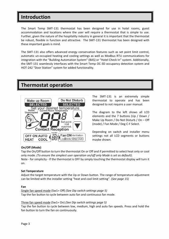
The SMT-131 is an extremely simple thermostat to operate and has been designed to not require a user manual. The diagram to the left shows all LCD elements and the 7 buttons (Up / Down / Make Up Room / Do Not Disturb / On – Off (mode) / Fan Mode / Deg C-F Select. Depending on switch and installer menu settings not all LCD segments or buttons maybe shown.
On/Off (Mode) Tap the On/Off button to turn the thermostat On or Off and if permitted to select heat only or cool only mode. (To ensure the simplest user operation on/off only Mode is set as default). Note - for simplicity - If the thermostat is OFF by simply touching the thermostat display will turn it on. Set Temperature Adjust the target temperature with the Up or Down button. The range of temperature adjustment can be limited with the installer setting “heat and cool limit setting”. (See page 15) Fan Single fan speed mode (Sw1= Off) (See Dip switch settings page 5) Tap the fan button to cycle between auto fan and continuous fan mode. Three fan speed mode (Sw1= On) (See Dip switch settings page 5) Tap the fan button to cycle between low, medium, high and auto fan speeds. Press and hold the fan button to turn the fan on continuously.
Page 4
Note. Option 16 in the installer menu (See page 16) permits you to set the SMT-131 to automatically reset the indoor fan to Automatic Mode (cycle on and off with heating and cooling) every time the thermostat is turned off and then back on if desired. If Auto Fan mode is selected, then when the heating and cooling stops, so will the fan (after any purge periods have expired if set- see page 15) If Fan On mode is selected, then the fan will continue to run after the heating and cooling stops to maintain ventilation. Ventilation Mode If permitted by DIP Sw7, (See page 5) the user can run the indoor fan only (Ventilation Mode) when the SMT-131 is off by tapping the fan button. Each tap of the fan button will cycle between all available fan speeds. “Make up Room” & “Do Not Disturb” Buttons When enabled by DIP Sw8, (See page 5) pressing these buttons will activate relevant LCD segments and backlight colour on the optional outside door station as well as write data to Modbus for monitoring by a BAS system. Note - you do not need the outside door stations to be fitted if you simply wish this data to be presented to Modbus.
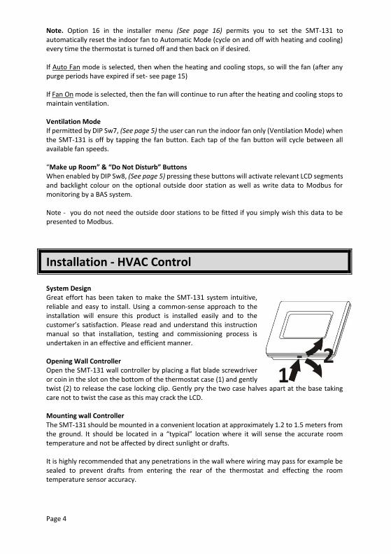
Installation - HVAC Control System Design Great effort has been taken to make the SMT-131 system intuitive, reliable and easy to install. Using a common-sense approach to the installation will ensure this product is installed easily and to the customer’s satisfaction. Please read and understand this instruction manual so that installation, testing and commissioning process is undertaken in an effective and efficient manner. Opening Wall Controller Open the SMT-131 wall controller by placing a flat blade screwdriver or coin in the slot on the bottom of the thermostat case (1) and gently twist (2) to release the case locking clip. Gently pry the two case halves apart at the base taking care not to twist the case as this may crack the LCD. Mounting wall Controller The SMT-131 should be mounted in a convenient location at approximately 1.2 to 1.5 meters from the ground. It should be located in a “typical” location where it will sense the accurate room temperature and not be affected by direct sunlight or drafts. It is highly recommended that any penetrations in the wall where wiring may pass for example be sealed to prevent drafts from entering the rear of the thermostat and effecting the room temperature sensor accuracy.
Page 5
Take care to ensure excess wiring is not trapped between the cases half’s when closing - push excess wires into the wall cavity. Never press on the LCD when closing the SMT-131 as it may crack. Always press on the SMT-131 plastic case only.
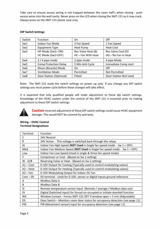
DIP Switch Settings
Switch Function On Off
Sw1 Indoor Fan Mode 3 Fan Speed 1 Fan Speed
Sw2 Equipment Type Heat Pump Heat Cool
Sw3 HP Mode (Sw2= ON) HC Mode (Sw2=OFF)
Rev Valve Heat (B) HE – Fan With Heat
Rev Valve Cool (O) HG – No Fan In Heat
Sw4 2 / 4 pipe mode 2 pipe mode 4 pipe Mode
Sw5 Comp Protection Delay 5 Min Anti Cycle Immediate Comp start
Sw6 Klixon (Ricardo) Mode On Off
Sw7 Ventilation Mode Permitted Not Permitted
Sw8 Door Station (Optional) Fitted Door Station Not Used
Note: The SMT-131 reads the switch settings on power up only. If you change any DIP switch settings you must power cycle before these changes will take effect. It is expected that only qualified people will make adjustment to these dip switch settings. Knowledge of the HVAC system under the control of the SMT-131 is essential prior to making adjustment to these DIP switch settings.
Caution Incorrect adjustment of these DIP switch settings could cause HVAC equipment
damage. This would NOT be covered by warranty. Wiring – HVAC Control Terminal Designations
Terminal Function
C 24V Neutral
R 24V Active - This voltage is switched back through the relays
Hi Indoor Fan High Speed (NOT Used in Single fan speed mode - Sw 1 = OFF)
Med Indoor Fan Medium Speed (NOT Used in Single fan speed mode - Sw 1 = OFF)
Low Indoor Fan Low Speed (Used in single & three fan speed mode)
Y Compressor or Cool - (Based on Sw 2 setting)
W - O/B Reversing Valve or Heat - (Based on Sw 2 setting)
A1 – Cool 0-10V Output for Cooling (Typically used to control modulating valves)
A2 – Heat 0-10V Output for Heating (Typically used to control modulating valves)
A3 – Fan 0-10V Modulating Output for Indoor DC Fan
Com – 0V 0V terminal - Used for 0-10V, sensor or digital inputs ground reference
A Modbus Data A
B Modbus Data B
SI Remote temperature sensor input (Remote / average / Modbus data use)
DI Digital (Switched input) for forced un-occupied or initiate doorbell function
WC Window Contact - Forces SMT-131 OFF if window open > 5 min (Adjustable)
DS Door Switch – Monitors room door status for occupancy detection (see page 11)
PIR PIR (Movement sensor) input for occupancy detection (see page 11)
Page 6
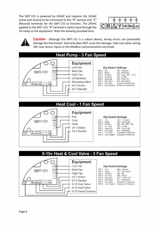
The SMT-131 is powered by 24VAC and requires the 24VAC active and neutral to be connected to the “R” (active) and “C” (Neutral) terminals for the SMT-131 to function. The 24VAC applied to the SMT-131 “R” terminal is switch back through the 2A relays to the equipment. Note the drawing provided here.
Caution - Although the SMT-131 is a robust device, wiring errors can potentially
damage the thermostat. Warranty does NOT cover this damage. Take care when wiring 24V near sensor inputs or the Modbus communications terminals.
Page 7
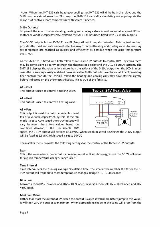
Note - When the SMT-131 calls heating or cooling the SMT-131 will drive both the relays and the 0-10V outputs simultaneously. This way the SMT-131 can call a circulating water pump via the relays as it controls room temperature with valves if needed. 0-10v Outputs To permit the control of modulating heating and cooling valves as well as variable speed DC fan motors or variable capacity HVAC systems the SMT-131 has been fitted with 3 x 0-10V outputs. The 0-10V outputs in the SMT-131 are PI (Proportional Integral) controlled. This control method provides the most accurate and cost effective way to control heating and cooling valves by ensuring set temperate are reached as quickly and efficiently as possible while reducing temperature overshoot. As the SMT-131 is fitted with both relays as well as 0-10V outputs to control HVAC systems there may be some slight disparity between the thermostat display and the 0-10V outputs actions. The SMT-131 displays the relay actions more than the actions of the 0-10V outputs on the LCD. In most cases these are very closely matched however as the 0-10v outputs have the capability of providing finer control than do the ON/OFF relays the heating and cooling calls may have started slightly before indicated on the thermostat display. This is true of the fan also. A1 – Cool This output is used to control a cooling valve. A2 – Heat This output is used to control a heating valve. A3 – Fan This output is used to control a variable speed fan or a variable capacity AC system. If the fan mode is set to Auto speed the 0-10V output will vary between these two values based on calculated demand. If the user selects LOW speed, the 0-10V output will be fixed at 3.3VDC, when Medium speed is selected the 0-10V output will be fixed at 6.6VDC. High speed is set to 10VDC The installer menu provides the following settings for the control of the three 0-10V outputs. Span This is the value where the output is at maximum value. It sets how aggressive the 0-10V will move for a given temperature change. Range is 0-5C Time Interval Time interval sets the running average calculation time. The smaller the number the faster the 0-10V output will respond to room temperature changes. Range is 10 – 300 seconds. Direction Forward action 0V = 0% open and 10V = 100% open; reverse action sets 0V = 100% open and 10V = 0% open. Minimum Value Rather than start the output at 0V, when the output is called it will immediately jump to this value. It will then vary the output to maximum. When approaching set point the value will drop from the
Page 8
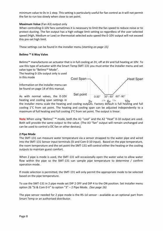
minimum value to 0v in 1 step. This setting is particularly useful for fan control as it will not permit the fan to run too slowly when close to set point. Maximum Value (Fan A3) output only When controlling 0-10V fans sometimes it is necessary to limit the fan speed to reduce noise or to protect ducting. The fan output has a high voltage limit setting so regardless of the user selected speed (High, Medium or Low) or thermostat selected auto speed the 0-10V output will not exceed this pre-set high limit. These settings can be found in the installer menu (starting on page 15) Belimo ™ 6 Way Valve Belimo™ manufactures an actuator that is in full cooling at 2V, off at 6V and full heating at 10V. To use this type of actuator with the Smart Temp SMT-131 you must enter the installer menu and set valve type to “Belimo™ Mode”. The heating 0-10v output only is used in this mode Information on the installer menu can be found on page 14 of this manual. As with normal valves, the 0-10V heating and cooling span settings in the installer menu scale the heating and cooling outputs. Factory default is full heating and full cooling 1°C from set point. The heating and cooling span can be adjusted independently to a maximum of full heating and full cooling 3°C from set point. The output is linear. Note When using “Belimo” ™ mode, both the A1 “cool” and the A2 “Heat” 0-10 output are used. Both will provide the same output to the value. (The A3 “fan” output will remain unchanged and can be used to control a DC fan or other devices). 2 Pipe Mode The SMT-131 can measure water temperature via a sensor strapped to the water pipe and wired into the SMT-131 Sensor input terminals (SI and Com 0-10 input). Based on the pipe temperature, the room temperature and the set point the SMT-131 will control either the heating or the cooling outputs to maintain guest comfort. When 2 pipe is mode is used, the SMT-131 will occasionally open the water valve to allow water flow within the pipe so the SMT-131 can sample pipe temperature to determine / confirm operation mode. If mode selection is permitted, the SMT-131 will only permit the appropriate mode to be selected based on the pipe temperature. To use the SMT-131 in 2 pipe mode set DIP 2 OFF and DIP 4 to the ON position. Set Installer menu option 26 “Si & Com 0-V” to option “3” – 2 Pipe Mode. (See page 16) The pipe sensor needed for 2 pipe mode is the RS-1d sensor - available as an optional part from Smart Temp or an authorised distributor.
Page 9
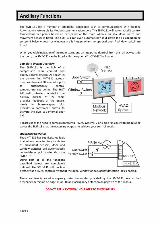
Ancillary Functions The SMT-131 has a number of additional capabilities such as communications with Building Automation systems via its Modbus communications port. The SMT-131 will automatically control temperature set points based on occupancy of the room when a suitable door switch and movement sensor is fitted. The SMT-131 can even automatically shut down the air conditioning system if balcony doors or windows are left open when the optional door / window switch are fitted. When you wish indication of the room status and an integrated doorbell from the hall way outside the room, the SMT-131 can be fitted with the optional “HOT-243” hall panel. Complete System Overview The SMT-131 is the hub of a compressive room comfort and energy control system. As shown in the picture the SMT-131 accepts door, window and PIR contact inputs to automatically control temperature set points. The HOT 243 wall controller mounted in the hallway outside of the room provides feedback of the guests needs to housekeeping plus provides a convenient button to activate the SMT-131 internal door bell. Regardless of the need to control conferential HVAC systems, 2 or 4 pipe fan coils with modulating valves the SMT-131 has the necessary outputs to achieve your control needs. Occupancy Detection The SMT-131 has sophisticated logic that when connected to your choice of movement sensors, door and window switches will automatically control the set point and mode of the SMT-131. Using part or all the functions described below are completely optional. The SMT-131 will function perfectly as a HVAC controller without the door, window or occupancy detection logic enabled. There are two types of occupancy detection modes provided by the SMT-131, see latched occupancy detection on page 11 or PIR only occupancy detection on page 12 of this manual.
DO NOT APPLY EXTERNAL VOLTAGES TO THESE INPUTS
Page 10
Window Contact The window contact input (WC) is used to automatically disable the HVAC system if a window is left open. This is done to prevent energy waste by trying to heat or cool an open room. The SMT-131 window input can be set for a Normally Open (switch open when window is closed) or normally closed logic (switch closed when window is closed). When the window is left open for longer than the pre-set time (0 to 300 seconds) the SMT-131 will automatically turn OFF. The text “OFF” will flash in the LCD to indicate that the remote window (or door switch) is holding the SMT-131 in off mode. The wall controller will prohibit all changes. The SMT-131 will automatically restart once the window is closed. The Installer menu option 28 “Window Input Logic” and option 29 “Window Input Delay” (page16) sets the window detection logic in the SMT-131. Fault Indication The SMT-131 can display the text “FLt” alternating with the temperature should you wish to alert the user of an external fault with the heating or cooling system. To enable this function, enter the installer menu and set the Window contact input setting 31 to option 3. (See page 16 for this setting). When the WC terminal and the Com-0V terminal are joined the SMT-131 will alternate “FLt” with the current room temperature. Register 32 will permit a time delay to be set after the fault signal is received if necessary to reduce false trips. The fault indication has NO effect on thermostat function Door Switch The Door switch input (DS) is used by the SMT-131 for 3 functions.
1) To detect that the door has been opened and then closed to let somebody into or out of the room.
2) To detect if the door has been left open. 3) To use as an occupancy or Auto-Off timer in training rooms or similar.
The SMT door switch input can be set for a Normally Open (switch open when door is closed) or normally closed logic (switch closed when door is closed) or OFF (input not used). The Installer menu 30 “Door Input Logic” and option 31“Door Input Delay” (page 16) sets the door detection logic in the SMT-131. Entering or exiting the room. Once the door is opened and then closed the SMT-131 will begin its occupancy detection process using the PIR input described below. Based on the outcome of this process the SMT-131 will remain on and permit guest interaction with the SMT-131 (adjust mode and set point for example), or switch to “un-occupied” mode where the SMT-131 will substitute the guest set point and mode for the installer pre-set values.
Page 11
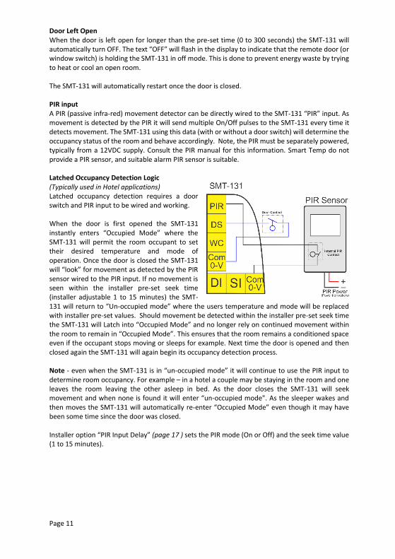
Door Left Open When the door is left open for longer than the pre-set time (0 to 300 seconds) the SMT-131 will automatically turn OFF. The text “OFF” will flash in the display to indicate that the remote door (or window switch) is holding the SMT-131 in off mode. This is done to prevent energy waste by trying to heat or cool an open room. The SMT-131 will automatically restart once the door is closed. PIR input A PIR (passive infra-red) movement detector can be directly wired to the SMT-131 “PIR” input. As movement is detected by the PIR it will send multiple On/Off pulses to the SMT-131 every time it detects movement. The SMT-131 using this data (with or without a door switch) will determine the occupancy status of the room and behave accordingly. Note, the PIR must be separately powered, typically from a 12VDC supply. Consult the PIR manual for this information. Smart Temp do not provide a PIR sensor, and suitable alarm PIR sensor is suitable. Latched Occupancy Detection Logic (Typically used in Hotel applications) Latched occupancy detection requires a door switch and PIR input to be wired and working. When the door is first opened the SMT-131 instantly enters “Occupied Mode” where the SMT-131 will permit the room occupant to set their desired temperature and mode of operation. Once the door is closed the SMT-131 will “look” for movement as detected by the PIR sensor wired to the PIR input. If no movement is seen within the installer pre-set seek time (installer adjustable 1 to 15 minutes) the SMT-131 will return to “Un-occupied mode” where the users temperature and mode will be replaced with installer pre-set values. Should movement be detected within the installer pre-set seek time the SMT-131 will Latch into “Occupied Mode” and no longer rely on continued movement within the room to remain in “Occupied Mode”. This ensures that the room remains a conditioned space even if the occupant stops moving or sleeps for example. Next time the door is opened and then closed again the SMT-131 will again begin its occupancy detection process. Note - even when the SMT-131 is in “un-occupied mode” it will continue to use the PIR input to determine room occupancy. For example – in a hotel a couple may be staying in the room and one leaves the room leaving the other asleep in bed. As the door closes the SMT-131 will seek movement and when none is found it will enter “un-occupied mode". As the sleeper wakes and then moves the SMT-131 will automatically re-enter “Occupied Mode” even though it may have been some time since the door was closed. Installer option “PIR Input Delay” (page 17 ) sets the PIR mode (On or Off) and the seek time value (1 to 15 minutes).
Page 12
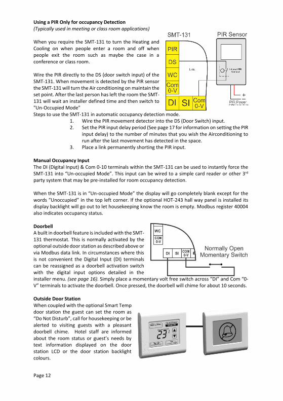
Using a PIR Only for occupancy Detection (Typically used in meeting or class room applications) When you require the SMT-131 to turn the Heating and Cooling on when people enter a room and off when people exit the room such as maybe the case in a conference or class room. Wire the PIR directly to the DS (door switch input) of the SMT-131. When movement is detected by the PIR sensor the SMT-131 will turn the Air conditioning on maintain the set point. After the last person has left the room the SMT-131 will wait an installer defined time and then switch to "Un-Occupied Mode" Steps to use the SMT-131 in automatic occupancy detection mode.
1. Wire the PIR movement detector into the DS (Door Switch) input. 2. Set the PIR input delay period (See page 17 for information on setting the PIR
input delay) to the number of minutes that you wish the Airconditioning to run after the last movement has detected in the space.
3. Place a link permanently shorting the PIR input. Manual Occupancy Input The DI (Digital Input) & Com 0-10 terminals within the SMT-131 can be used to instantly force the SMT-131 into “Un-occupied Mode”. This input can be wired to a simple card reader or other 3rd party system that may be pre-installed for room occupancy detection. When the SMT-131 is in “Un-occupied Mode” the display will go completely blank except for the words “Unoccupied” in the top left corner. If the optional HOT-243 hall way panel is installed its display backlight will go out to let housekeeping know the room is empty. Modbus register 40004 also indicates occupancy status. Doorbell A built in doorbell feature is included with the SMT-131 thermostat. This is normally activated by the optional outside door station as described above or via Modbus data link. In circumstances where this is not convenient the Digital Input (DI) terminals can be reassigned as a doorbell activation switch with the digital input options detailed in the installer menu. (see page 16). Simply place a momentary volt free switch across “DI” and Com “0-V” terminals to activate the doorbell. Once pressed, the doorbell will chime for about 10 seconds. Outside Door Station When coupled with the optional Smart Temp door station the guest can set the room as “Do Not Disturb”, call for housekeeping or be alerted to visiting guests with a pleasant doorbell chime. Hotel staff are informed about the room status or guest’s needs by text information displayed on the door station LCD or the door station backlight colours.
Page 13
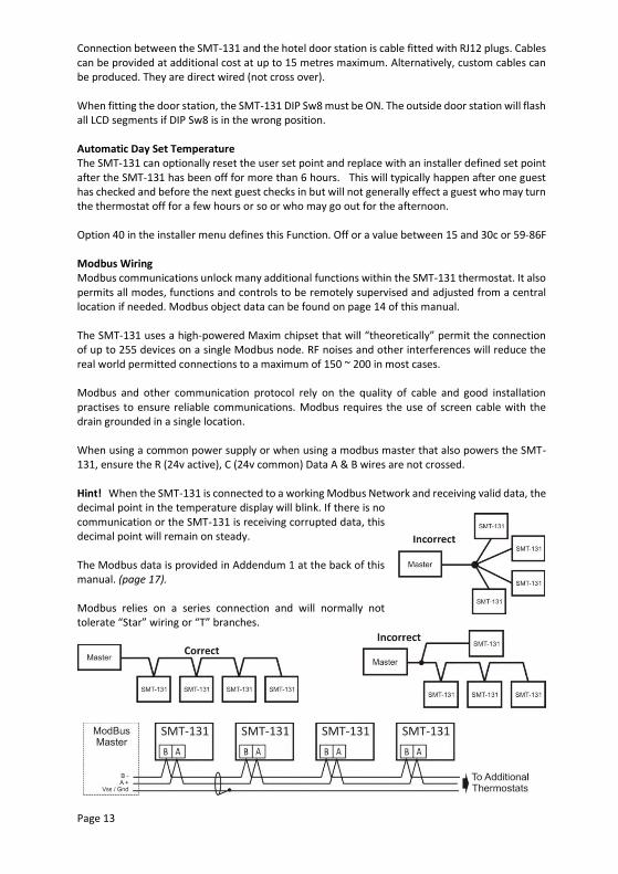
Connection between the SMT-131 and the hotel door station is cable fitted with RJ12 plugs. Cables can be provided at additional cost at up to 15 metres maximum. Alternatively, custom cables can be produced. They are direct wired (not cross over). When fitting the door station, the SMT-131 DIP Sw8 must be ON. The outside door station will flash all LCD segments if DIP Sw8 is in the wrong position. Automatic Day Set Temperature The SMT-131 can optionally reset the user set point and replace with an installer defined set point after the SMT-131 has been off for more than 6 hours. This will typically happen after one guest has checked and before the next guest checks in but will not generally effect a guest who may turn the thermostat off for a few hours or so or who may go out for the afternoon. Option 40 in the installer menu defines this Function. Off or a value between 15 and 30c or 59-86F Modbus Wiring Modbus communications unlock many additional functions within the SMT-131 thermostat. It also permits all modes, functions and controls to be remotely supervised and adjusted from a central location if needed. Modbus object data can be found on page 14 of this manual. The SMT-131 uses a high-powered Maxim chipset that will “theoretically” permit the connection of up to 255 devices on a single Modbus node. RF noises and other interferences will reduce the real world permitted connections to a maximum of 150 ~ 200 in most cases. Modbus and other communication protocol rely on the quality of cable and good installation practises to ensure reliable communications. Modbus requires the use of screen cable with the drain grounded in a single location. When using a common power supply or when using a modbus master that also powers the SMT-131, ensure the R (24v active), C (24v common) Data A & B wires are not crossed. Hint! When the SMT-131 is connected to a working Modbus Network and receiving valid data, the decimal point in the temperature display will blink. If there is no communication or the SMT-131 is receiving corrupted data, this decimal point will remain on steady. The Modbus data is provided in Addendum 1 at the back of this manual. (page 17). Modbus relies on a series connection and will normally not tolerate “Star” wiring or “T” branches.
Page 14
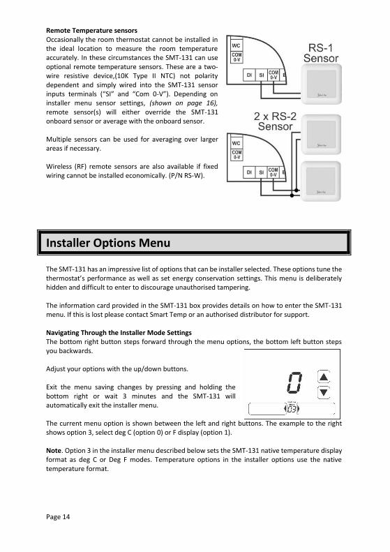
Remote Temperature sensors Occasionally the room thermostat cannot be installed in the ideal location to measure the room temperature accurately. In these circumstances the SMT-131 can use optional remote temperature sensors. These are a two-wire resistive device,(10K Type II NTC) not polarity dependent and simply wired into the SMT-131 sensor inputs terminals (“SI” and “Com 0-V”). Depending on installer menu sensor settings, (shown on page 16), remote sensor(s) will either override the SMT-131 onboard sensor or average with the onboard sensor. Multiple sensors can be used for averaging over larger areas if necessary. Wireless (RF) remote sensors are also available if fixed wiring cannot be installed economically. (P/N RS-W).
Installer Options Menu The SMT-131 has an impressive list of options that can be installer selected. These options tune the thermostat’s performance as well as set energy conservation settings. This menu is deliberately hidden and difficult to enter to discourage unauthorised tampering. The information card provided in the SMT-131 box provides details on how to enter the SMT-131 menu. If this is lost please contact Smart Temp or an authorised distributor for support. Navigating Through the Installer Mode Settings The bottom right button steps forward through the menu options, the bottom left button steps you backwards. Adjust your options with the up/down buttons. Exit the menu saving changes by pressing and holding the bottom right or wait 3 minutes and the SMT-131 will automatically exit the installer menu. The current menu option is shown between the left and right buttons. The example to the right shows option 3, select deg C (option 0) or F display (option 1). Note. Option 3 in the installer menu described below sets the SMT-131 native temperature display format as deg C or Deg F modes. Temperature options in the installer options use the native temperature format.
Page 15
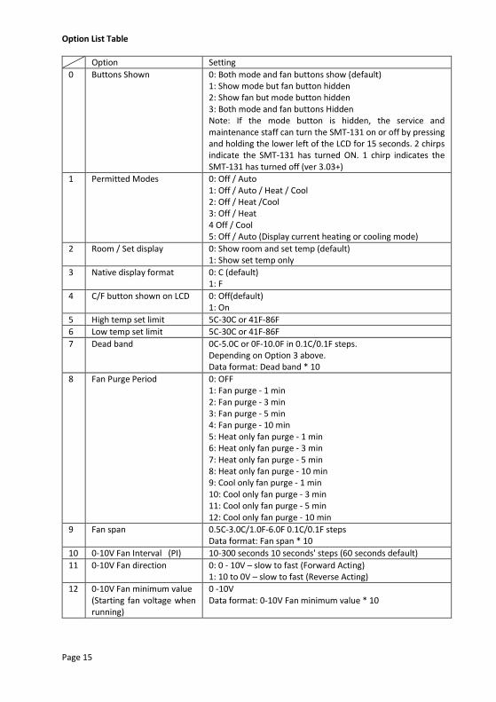
Option List Table
Option Setting
0 Buttons Shown 0: Both mode and fan buttons show (default) 1: Show mode but fan button hidden 2: Show fan but mode button hidden 3: Both mode and fan buttons Hidden Note: If the mode button is hidden, the service and maintenance staff can turn the SMT-131 on or off by pressing and holding the lower left of the LCD for 15 seconds. 2 chirps indicate the SMT-131 has turned ON. 1 chirp indicates the SMT-131 has turned off (ver 3.03+)
1 Permitted Modes 0: Off / Auto 1: Off / Auto / Heat / Cool 2: Off / Heat /Cool 3: Off / Heat 4 Off / Cool 5: Off / Auto (Display current heating or cooling mode)
2 Room / Set display 0: Show room and set temp (default) 1: Show set temp only
3 Native display format 0: C (default) 1: F
4 C/F button shown on LCD 0: Off(default) 1: On
5 High temp set limit 5C-30C or 41F-86F
6 Low temp set limit 5C-30C or 41F-86F
7 Dead band 0C-5.0C or 0F-10.0F in 0.1C/0.1F steps. Depending on Option 3 above. Data format: Dead band * 10
8 Fan Purge Period 0: OFF 1: Fan purge - 1 min 2: Fan purge - 3 min 3: Fan purge - 5 min 4: Fan purge - 10 min 5: Heat only fan purge - 1 min 6: Heat only fan purge - 3 min 7: Heat only fan purge - 5 min 8: Heat only fan purge - 10 min 9: Cool only fan purge - 1 min 10: Cool only fan purge - 3 min 11: Cool only fan purge - 5 min 12: Cool only fan purge - 10 min
9 Fan span
0.5C-3.0C/1.0F-6.0F 0.1C/0.1F steps Data format: Fan span * 10
10 0-10V Fan Interval (PI) 10-300 seconds 10 seconds' steps (60 seconds default)
11 0-10V Fan direction 0: 0 - 10V – slow to fast (Forward Acting) 1: 10 to 0V – slow to fast (Reverse Acting)
12 0-10V Fan minimum value (Starting fan voltage when running)
0 -10V Data format: 0-10V Fan minimum value * 10
Page 16
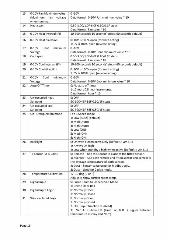
13 0-10V Fan Maximum value (Maximum fan voltage when running)
0 -10V Data format: 0-10V Fan minimum value * 10
14 Heat span 0.5C-3.0C/1.0F-6.0F 0.1C/0.1F steps Data format: Fan span * 10
15 0-10V Heat interval (PI) 10-300 seconds 10 seconds' steps (60 seconds default)
16 0-10V Heat direction 0: 10V is 100% open (forward acting) 1: 0V is 100% open (reverse acting)
17 0-10V Heat minimum Voltage
0 -10V Data format: 0-10V Heat minimum value * 10
18 Cool span 0.5C-3.0C/1.0F-6.0F 0.1C/0.1F steps Data format: Fan span * 10
19 0-10V Cool interval (PI) 10-300 seconds 10 seconds' steps (60 seconds default)
20 0-10V Cool direction 0: 10V is 100% open (forward acting) 1: 0V is 100% open (reverse acting)
21 0-10V Cool minimum Voltage
0 -10V Data format: 0-10V Cool minimum value * 10
22 Auto Off Timer 0: No auto off timer 1-10hours 0.5 hour increments. Data format: hour * 10
23 Un-occupied heat Set point
0: OFF 5C-30C/41F-86F 0.5C/1F steps
24 Un-occupied cool Set point
0: OFF 5C-30C/41F-86F 0.5C/1F steps
25 Un –Occupied fan mode Fan 3 Speed mode 1: Low (Auto) (default) 2: Med (Auto) 3: High (Auto) 4: Low (ON) 5: Med (ON) 6: High (ON)
26 Backlight 0: On with button press Only (Default > ver 3.1) 1: Always On high 2: Low when standby / high when active (Default < ver 3.1)
27 TT sensor (SI & Com)
0: Remote – Use this sensor in place of the fitted sensor. 1: Average – Use both remote and fitted sensor and control to the average temperature of both sensors. 2: Data – Sensor value used for Modbus only. 3: Duct – Used for 2 pipe mode.
28 Temperature Calibration +/- 10 deg (C or F) Adjust to show correct room temp.
29 Digital Input 0: Force Room to Unoccupied Mode 1: Chime Door Bell
30 Digital Input Logic 0: Normally Open 1: Normally Closed
31 Window Input Logic 0: Normally Open 1: Normally closed 2: OFF (Input function disabled) 3: Ver 3.3+ Show FLt (Fault) on LCD (Toggles between temperature display and “FLt”)
Page 17
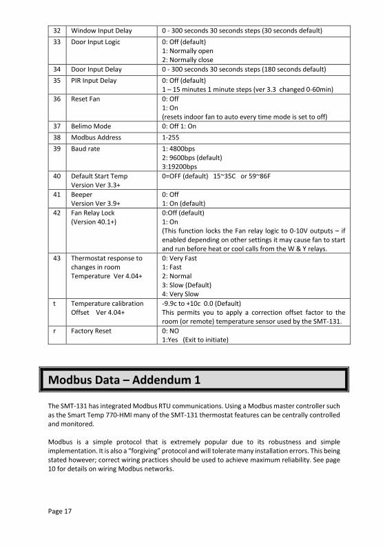
32 Window Input Delay 0 - 300 seconds 30 seconds steps (30 seconds default)
33 Door Input Logic 0: Off (default) 1: Normally open 2: Normally close
34 Door Input Delay 0 - 300 seconds 30 seconds steps (180 seconds default)
35 PIR Input Delay 0: Off (default) 1 – 15 minutes 1 minute steps (ver 3.3 changed 0-60min)
36 Reset Fan
0: Off 1: On (resets indoor fan to auto every time mode is set to off)
37 Belimo Mode 0: Off 1: On
38 Modbus Address 1-255
39 Baud rate 1: 4800bps 2: 9600bps (default) 3:19200bps
40 Default Start Temp Version Ver 3.3+
0=OFF (default) 15~35C or 59~86F
41 Beeper Version Ver 3.9+
0: Off 1: On (default)
42 Fan Relay Lock (Version 40.1+)
0:Off (default) 1: On (This function locks the Fan relay logic to 0-10V outputs – if enabled depending on other settings it may cause fan to start and run before heat or cool calls from the W & Y relays.
43 Thermostat response to changes in room Temperature Ver 4.04+
0: Very Fast 1: Fast 2: Normal 3: Slow (Default) 4: Very Slow
t Temperature calibration Offset Ver 4.04+
-9.9c to +10c 0.0 (Default) This permits you to apply a correction offset factor to the room (or remote) temperature sensor used by the SMT-131.
r Factory Reset 0: NO 1:Yes (Exit to initiate)
Modbus Data – Addendum 1 The SMT-131 has integrated Modbus RTU communications. Using a Modbus master controller such as the Smart Temp 770-HMI many of the SMT-131 thermostat features can be centrally controlled and monitored. Modbus is a simple protocol that is extremely popular due to its robustness and simple implementation. It is also a “forgiving” protocol and will tolerate many installation errors. This being stated however; correct wiring practices should be used to achieve maximum reliability. See page 10 for details on wiring Modbus networks.
Page 18
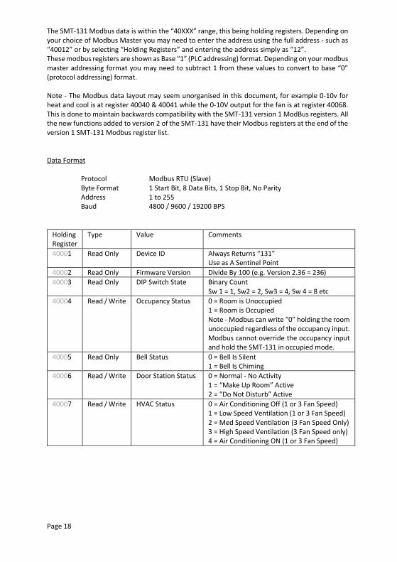
The SMT-131 Modbus data is within the “40XXX” range, this being holding registers. Depending on your choice of Modbus Master you may need to enter the address using the full address - such as “40012” or by selecting “Holding Registers” and entering the address simply as “12”. These modbus registers are shown as Base “1” (PLC addressing) format. Depending on your modbus master addressing format you may need to subtract 1 from these values to convert to base “0” (protocol addressing) format. Note - The Modbus data layout may seem unorganised in this document, for example 0-10v for heat and cool is at register 40040 & 40041 while the 0-10V output for the fan is at register 40068. This is done to maintain backwards compatibility with the SMT-131 version 1 ModBus registers. All the new functions added to version 2 of the SMT-131 have their Modbus registers at the end of the version 1 SMT-131 Modbus register list. Data Format
Protocol Modbus RTU (Slave) Byte Format 1 Start Bit, 8 Data Bits, 1 Stop Bit, No Parity Address 1 to 255 Baud 4800 / 9600 / 19200 BPS
Holding Register
Type Value Comments
40001 Read Only Device ID Always Returns “131” Use as A Sentinel Point
40002 Read Only Firmware Version Divide By 100 (e.g. Version 2.36 = 236)
40003 Read Only DIP Switch State Binary Count Sw 1 = 1, Sw2 = 2, Sw3 = 4, Sw 4 = 8 etc
40004 Read / Write Occupancy Status 0 = Room is Unoccupied 1 = Room is Occupied Note - Modbus can write “0” holding the room unoccupied regardless of the occupancy input. Modbus cannot override the occupancy input and hold the SMT-131 in occupied mode.
40005 Read Only Bell Status 0 = Bell Is Silent 1 = Bell Is Chiming
40006 Read / Write Door Station Status 0 = Normal - No Activity 1 = “Make Up Room” Active 2 = “Do Not Disturb” Active
40007 Read / Write HVAC Status 0 = Air Conditioning Off (1 or 3 Fan Speed) 1 = Low Speed Ventilation (1 or 3 Fan Speed) 2 = Med Speed Ventilation (3 Fan Speed Only) 3 = High Speed Ventilation (3 Fan Speed only) 4 = Air Conditioning ON (1 or 3 Fan Speed)
Page 19
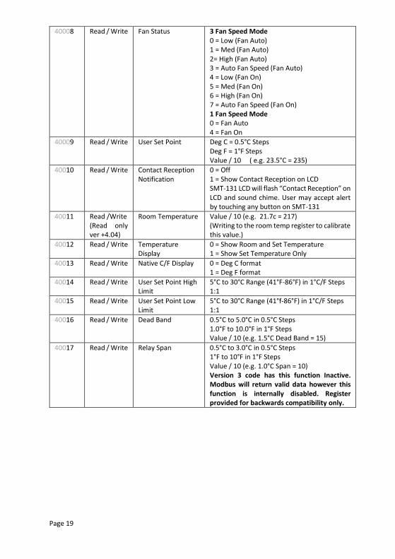
40008 Read / Write Fan Status 3 Fan Speed Mode 0 = Low (Fan Auto) 1 = Med (Fan Auto) 2= High (Fan Auto) 3 = Auto Fan Speed (Fan Auto) 4 = Low (Fan On) 5 = Med (Fan On) 6 = High (Fan On) 7 = Auto Fan Speed (Fan On) 1 Fan Speed Mode 0 = Fan Auto 4 = Fan On
40009 Read / Write User Set Point Deg C = 0.5°C Steps Deg F = 1°F Steps Value / 10 ( e.g. 23.5°C = 235)
40010 Read / Write Contact Reception Notification
0 = Off 1 = Show Contact Reception on LCD SMT-131 LCD will flash “Contact Reception” on LCD and sound chime. User may accept alert by touching any button on SMT-131
40011 Read /Write (Read only ver +4.04)
Room Temperature Value / 10 (e.g. 21.7c = 217) (Writing to the room temp register to calibrate this value.)
40012 Read / Write Temperature Display
0 = Show Room and Set Temperature 1 = Show Set Temperature Only
40013 Read / Write Native C/F Display 0 = Deg C format 1 = Deg F format
40014 Read / Write User Set Point High Limit
5°C to 30°C Range (41°F-86°F) in 1°C/F Steps 1:1
40015 Read / Write User Set Point Low Limit
5°C to 30°C Range (41°f-86°F) in 1°C/F Steps 1:1
40016 Read / Write Dead Band 0.5°C to 5.0°C in 0.5°C Steps 1.0°F to 10.0°F in 1°F Steps Value / 10 (e.g. 1.5°C Dead Band = 15)
40017 Read / Write Relay Span 0.5°C to 3.0°C in 0.5°C Steps 1°F to 10°F in 1°F Steps Value / 10 (e.g. 1.0°C Span = 10) Version 3 code has this function Inactive. Modbus will return valid data however this function is internally disabled. Register provided for backwards compatibility only.
Page 20
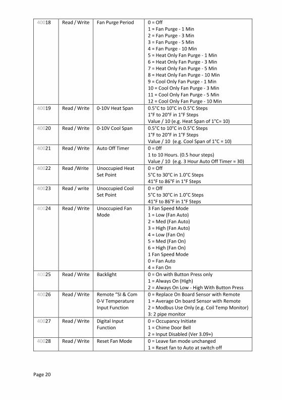
40018 Read / Write Fan Purge Period 0 = Off 1 = Fan Purge - 1 Min 2 = Fan Purge - 3 Min 3 = Fan Purge - 5 Min 4 = Fan Purge - 10 Min 5 = Heat Only Fan Purge - 1 Min 6 = Heat Only Fan Purge - 3 Min 7 = Heat Only Fan Purge - 5 Min 8 = Heat Only Fan Purge - 10 Min 9 = Cool Only Fan Purge - 1 Min 10 = Cool Only Fan Purge - 3 Min 11 = Cool Only Fan Purge - 5 Min 12 = Cool Only Fan Purge - 10 Min
40019 Read / Write 0-10V Heat Span 0.5°C to 10°C in 0.5°C Steps 1°F to 20°F in 1°F Steps Value / 10 (e.g. Heat Span of 1°C= 10)
40020 Read / Write 0-10V Cool Span 0.5°C to 10°C in 0.5°C Steps 1°F to 20°F in 1°F Steps Value / 10 (e.g. Cool Span of 1°C = 10)
40021 Read / Write Auto Off Timer 0 = 0ff 1 to 10 Hours. (0.5 hour steps) Value / 10 (e.g. 3 Hour Auto Off Timer = 30)
40022 Read /Write Unoccupied Heat Set Point
0 = Off 5°C to 30°C in 1.0°C Steps 41°F to 86°F in 1°F Steps
40023 Read / write Unoccupied Cool Set Point
0 = Off 5°C to 30°C in 1.0°C Steps 41°F to 86°F in 1°F Steps
40024 Read / Write Unoccupied Fan Mode
3 Fan Speed Mode 1 = Low (Fan Auto) 2 = Med (Fan Auto) 3 = High (Fan Auto) 4 = Low (Fan On) 5 = Med (Fan On) 6 = High (Fan On) 1 Fan Speed Mode 0 = Fan Auto 4 = Fan On
40025 Read / Write Backlight 0 = On with Button Press only 1 = Always On (High) 2 = Always On Low - High With Button Press
40026 Read / Write Remote “SI & Com 0-V Temperature Input Function
0 = Replace On Board Sensor with Remote 1 = Average On board Sensor with Remote 2 = Modbus Use Only (e.g. Coil Temp Monitor) 3: 2 pipe monitor
40027 Read / Write Digital Input Function
0 = Occupancy Initiate 1 = Chime Door Bell 2 = Input Disabled (Ver 3.09+)
40028 Read / Write Reset Fan Mode 0 = Leave fan mode unchanged 1 = Reset fan to Auto at switch off
Page 21
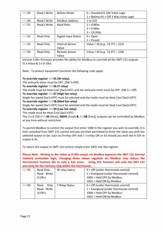
40029 Read / Write Belimo Mode
0 = Standard 0-10V Valve Logic 1 = Belimo 6V = Off 3 Way Valve Logic
40030 Read / Write Modbus Address 1 to 255
40031 Read / Write Baud Rate 1 = 4.8Kbs 2 = 9.6kbs 3 = 19.2Kbs
40032 Read Only Digital Input Status 0 = Open 1 = Closed
40033 Read Only Internal Sensor Value
Value / 10 (e.g. 23.3°C = 233)
40034 Read Only Remote Sensor Value
Value / 10 (e.g. 21.8°C = 218)
Version 3.09+ firmware provides the ability for Modbus to override all the SMT-131 outputs. (5 x relays & 3 x 0-10v). Note - To protect equipment functions the following rules apply. To override register 40035 (W relay). The anticycle timer must be OFF. (SW 5=Off). To override register 40036 (Y relay) The mode must be Heat Cool (Sw2=OFF) and the anticycle timer must be OFF. (SW 5 = Off) To override register 40037 (High fan relay) Single fan speed (Sw1=OFF) must be selected and the mode must be Heat Cool (Sw2=OFF) To override register 40038 (Med fan relay) Single fan speed (Sw1=OFF) must be selected and the mode must be Heat Cool (Sw2=OFF) To override register 40039 (Low fan relay) The mode must be Heat Cool (Sw2=OFF) The 3 x 0-10V (40040 (Heat), 40041 (Cool) & 40068 (Fan)), outputs can be controlled by Modbus at any time without restriction. To permit Modbus to control the output first enter 1000 in the register you wish to override, it is then unlocked from SMT-131 control and you are then permitted to enter the value you wish the selected output to be; such as 0=relay OFF and 1 1=relay ON or 63 should you wish the 0-10v to output 6.3v. To return the output to SMT-131 control simply enter 1001 into the register. Please Note - Writing to the relays or 0-10V output via Modbus bypasses the SMT-131 internal memory protection logic. Changing these values regularly via Modbus may reduce the thermostats memory life to only a few years. Using this function will void the SMT-131 warranty for the memory chip within the thermostat.
40035 Read Only Read Write (3.09+)
W relay status 0 = Off (under thermostat control) 1 = Energised (under thermostat control) 1000 = Held OFF by Modbus 1001 = Held ON by Modbus
40036 Read Only Read Write (3.09+)
Y Relay Status 0 = Off (under thermostat control) 1 = Energised (under thermostat control) 1000 = Held OFF by Modbus 1001 = Held ON by Modbus
Page 22
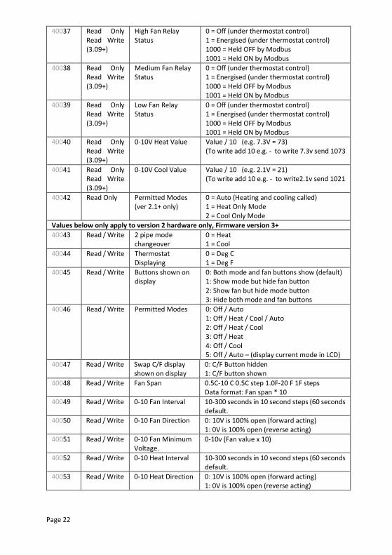
40037 Read Only Read Write (3.09+)
High Fan Relay Status
0 = Off (under thermostat control) 1 = Energised (under thermostat control) 1000 = Held OFF by Modbus 1001 = Held ON by Modbus
40038 Read Only Read Write (3.09+)
Medium Fan Relay Status
0 = Off (under thermostat control) 1 = Energised (under thermostat control) 1000 = Held OFF by Modbus 1001 = Held ON by Modbus
40039 Read Only Read Write (3.09+)
Low Fan Relay Status
0 = Off (under thermostat control) 1 = Energised (under thermostat control) 1000 = Held OFF by Modbus 1001 = Held ON by Modbus
40040 Read Only Read Write (3.09+)
0-10V Heat Value Value / 10 (e.g. 7.3V = 73) (To write add 10 e.g. - to write 7.3v send 1073
40041 Read Only Read Write (3.09+)
0-10V Cool Value Value / 10 (e.g. 2.1V = 21) (To write add 10 e.g. - to write2.1v send 1021
40042
Read Only Permitted Modes (ver 2.1+ only)
0 = Auto (Heating and cooling called) 1 = Heat Only Mode 2 = Cool Only Mode
Values below only apply to version 2 hardware only, Firmware version 3+
40043
Read / Write 2 pipe mode changeover
0 = Heat 1 = Cool
40044
Read / Write Thermostat Displaying
0 = Deg C 1 = Deg F
40045
Read / Write Buttons shown on display
0: Both mode and fan buttons show (default) 1: Show mode but hide fan button 2: Show fan but hide mode button 3: Hide both mode and fan buttons
40046
Read / Write Permitted Modes 0: Off / Auto 1: Off / Heat / Cool / Auto 2: Off / Heat / Cool 3: Off / Heat 4: Off / Cool 5: Off / Auto – (display current mode in LCD)
40047
Read / Write Swap C/F display shown on display
0: C/F Button hidden 1: C/F button shown
40048
Read / Write Fan Span 0.5C-10 C 0.5C step 1.0F-20 F 1F steps Data format: Fan span * 10
40049
Read / Write 0-10 Fan Interval 10-300 seconds in 10 second steps (60 seconds default.
40050
Read / Write 0-10 Fan Direction 0: 10V is 100% open (forward acting) 1: 0V is 100% open (reverse acting)
40051
Read / Write 0-10 Fan Minimum Voltage.
0-10v (Fan value x 10)
40052
Read / Write 0-10 Heat Interval 10-300 seconds in 10 second steps (60 seconds default.
40053
Read / Write 0-10 Heat Direction 0: 10V is 100% open (forward acting) 1: 0V is 100% open (reverse acting)
Page 23
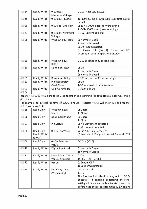
40054
Read / Write 0-10 Heat Minimum Voltage
0-10v (Heat value x 10)
40055
Read / Write 0-10 Cool Interval 10-300 seconds in 10 second steps (60 seconds default.
40056
Read / Write 0-10 Cool Direction 0: 10V is 100% open (forward acting) 1: 0V is 100% open (reverse acting)
40057
Read / Write 0-10 Cool Minimum Voltage
0-10v (Cool value x 10)
40058
Read / Write Window input logic 0: Normally Open 1: Normally closed 2: Off (input disabled) 3: Shows FLT (FAULT) shown on LCD alternating with temperature display.
40059 Read / Write Window input Delay
0-300 seconds in 30 second steps
40060
Read / Write Door input logic 0: Off 1: Normally Open 2: Normally closed
40061 Read / Write Door input Delay 0-300 seconds in 30 second steps
40062 Read / Write PIR input Delay (Seek Time)
0: Off 1-60 minutes in 1-minute steps
40063 40064
Read / Write Unit run time log 0-9999.9 hours
Register 40063 & 40064 are to be used together to determine the total Heat & Cool run time in 0.1 hours. For example, for a total run time of 15643.4 hours register 40064 will show 434 and register 40063 will show 156
40065 Read Only Window Input Status
0: Open 1: Closed
40066 Read Only Door Input Status 0: Open 1: Closed
40067 Read Only PIR Status 0: No Movement detected 1: Movement detected
40068 Read Only Read Write (3.09+)
0-10V Fan Value Value / 10 (e.g. 2.1V = 21) (To write add 10 e.g. - to write2.1v send 1021
40069 Read Only 0-10V Fan Max Value
0-10v (@*10)
40070 Read / Write Digital Input logic 0: Normally Open 1: Normally Closed
40071
Read / Write Default Start Temp Ver 3.3 firmware +
0: Off 15-35c or 59-86F
40072 Read / Write Beeper 0: Beeper OFF 1: Beeper On (Default)
40073 Read / Write Fan Relay Lock (Version 40.1+)
0: Off (default) 1: On This function locks the Fan relay logic to 0-10V outputs – if enabled depending on other settings it may cause fan to start and run before heat or cool calls from the W & Y relays.
Page 24
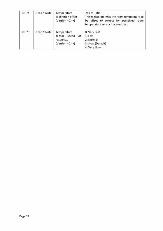
40074 Read / Write Temperature calibration offset (Version 40.4+)
-9.9 to +10c This register permits the room temperature to be offset to correct for perceived room temperature sensor inaccuracies.
40075 Read / Write Temperature sensor speed of response. (Version 40.4+)
0: Very Fast 1: Fast 2: Normal 3: Slow (Default) 4: Very Slow
Page 25
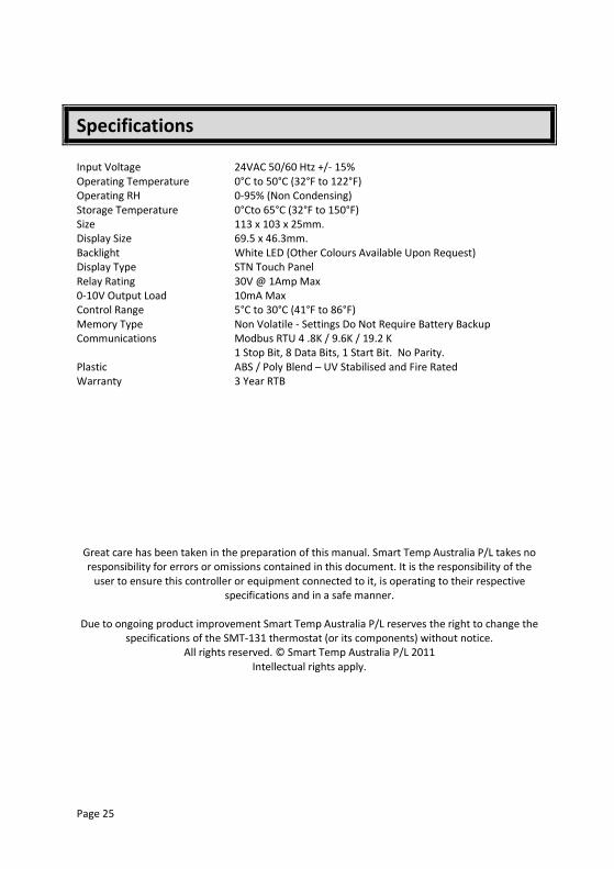
Specifications Input Voltage 24VAC 50/60 Htz +/- 15% Operating Temperature 0°C to 50°C (32°F to 122°F) Operating RH 0-95% (Non Condensing) Storage Temperature 0°Cto 65°C (32°F to 150°F) Size 113 x 103 x 25mm. Display Size 69.5 x 46.3mm. Backlight White LED (Other Colours Available Upon Request) Display Type STN Touch Panel Relay Rating 30V @ 1Amp Max 0-10V Output Load 10mA Max Control Range 5°C to 30°C (41°F to 86°F) Memory Type Non Volatile - Settings Do Not Require Battery Backup Communications Modbus RTU 4 .8K / 9.6K / 19.2 K 1 Stop Bit, 8 Data Bits, 1 Start Bit. No Parity. Plastic ABS / Poly Blend – UV Stabilised and Fire Rated Warranty 3 Year RTB
Great care has been taken in the preparation of this manual. Smart Temp Australia P/L takes no responsibility for errors or omissions contained in this document. It is the responsibility of the
user to ensure this controller or equipment connected to it, is operating to their respective specifications and in a safe manner.
Due to ongoing product improvement Smart Temp Australia P/L reserves the right to change the
specifications of the SMT-131 thermostat (or its components) without notice. All rights reserved. © Smart Temp Australia P/L 2011
Intellectual rights apply.