Embed Size (px)
Citation preview
© KEMET Electronics Corporation • KEMET Tower • One East Broward Boulevard A4082_ALC80 • 4/29/2019Fort Lauderdale, FL 33301 USA • 954-766-2800 • www.kemet.com
1One world. One KEMET
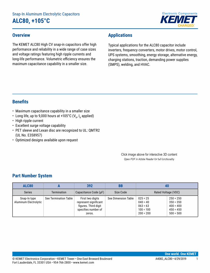
Benefits
• Maximum capacitance capability in a smaller size• Long life, up to 9,000 hours at +105°C (VR, IR applied)• High ripple current• Excellent surge voltage capability• PET sleeve and Lexan disc are recognized to UL: QMTR2
(UL No. E358957)• Optimized designs available upon request
Overview
The KEMET ALC80 High CV snap-in capacitors offer high performance and reliability in a wide range of case sizes and voltage ratings featuring high ripple currents and long-life performance. Volumetric efficiency ensures the maximum capacitance capability in a smaller size.
Applications
Typical applications for the ALC80 capacitor include inverters, frequency converters, motor drives, motor control, UPS systems, smoothing, energy storage, alternative energy, charging stations, traction, demanding power supplies (SMPS), welding, and HVAC.
Snap-In Aluminum Electrolytic Capacitors
ALC80, +105°C
Part Number System
ALC80 A 392 BB 40Series Termination Capacitance Code (µF) Size Code Rated Voltage (VDC)
Snap-In type Aluminum Electrolytic
See Termination Table First two digits represent significant
figures. Third digit specifies number of
zeros.
See Dimension Table 025 = 25 040 = 40 063 = 63 100 = 100 200 = 200
250 = 250 350 = 350 400 = 400 450 = 450 500 = 500
© KEMET Electronics Corporation • KEMET Tower • One East Broward Boulevard A4082_ALC80 • 4/29/2019Fort Lauderdale, FL 33301 USA • 954-766-2800 • www.kemet.com
2
Snap-In Aluminum Electrolytic Capacitors – ALC80, +105°C
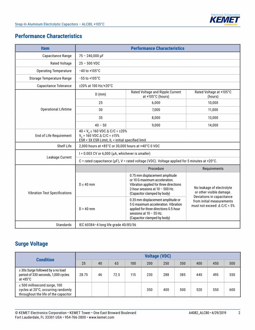
Performance Characteristics
Item Performance CharacteristicsCapacitance Range 75 – 240,000 µF
Rated Voltage 25 – 500 VDC
Operating Temperature −40 to +105°C
Storage Temperature Range −55 to +105°C
Capacitance Tolerance ±20% at 100 Hz/+20°C
Operational Lifetime
D (mm) Rated Voltage and Ripple Current at +105°C (hours)
Rated Voltage at +105°C (hours)
25 6,000 10,000
30 7,000 11,000
35 8,000 13,000
40 – 50 9,000 14,000
End of Life Requirement40 < VR ≤ 160 VDC ∆ C/C < ±20%VR > 160 VDC ∆ C/C < ±15%ESR < 3X ESR Limit, IL < initial specified limit
Shelf Life 2,000 hours at +85°C or 30,000 hours at +40°C 0 VDC
Leakage CurrentI = 0.003 CV or 6,000 (µA, whichever is smaller)
C = rated capacitance (µF), V = rated voltage (VDC). Voltage applied for 5 minutes at +20°C.
Vibration Test Specifications
Procedure Requirements
D ≤ 40 mm
0.75 mm displacement amplitude or 10 G maximum acceleration. Vibration applied for three directions 2-hour sessions at 10 – 500 Hz. (Capacitor clamped by body)
No leakage of electrolyte or other visible damage.
Deviations in capacitance from initial measurements
must not exceed: ∆ C/C < 5%D > 40 mm
0.35 mm displacement amplitude or 5 G maximum acceleration. Vibration applied for three directions 0.5-hour sessions at 10 – 55 Hz. (Capacitor clamped by body)
Standards IEC 60384–4 long life grade 40/85/56
Surge Voltage
ConditionVoltage (VDC)
25 40 63 100 200 250 350 400 450 500
≤ 30s Surge followed by a no load period of 330 seconds, 1,000 cycles at +85°C
28.75 46 72.5 115 230 288 385 440 495 550
≤ 500 millisecond surge, 100 cycles at 20°C, occurring randomly throughout the life of the capacitor
350 400 500 520 550 600
© KEMET Electronics Corporation • KEMET Tower • One East Broward Boulevard A4082_ALC80 • 4/29/2019Fort Lauderdale, FL 33301 USA • 954-766-2800 • www.kemet.com
3
Snap-In Aluminum Electrolytic Capacitors – ALC80, +105°C
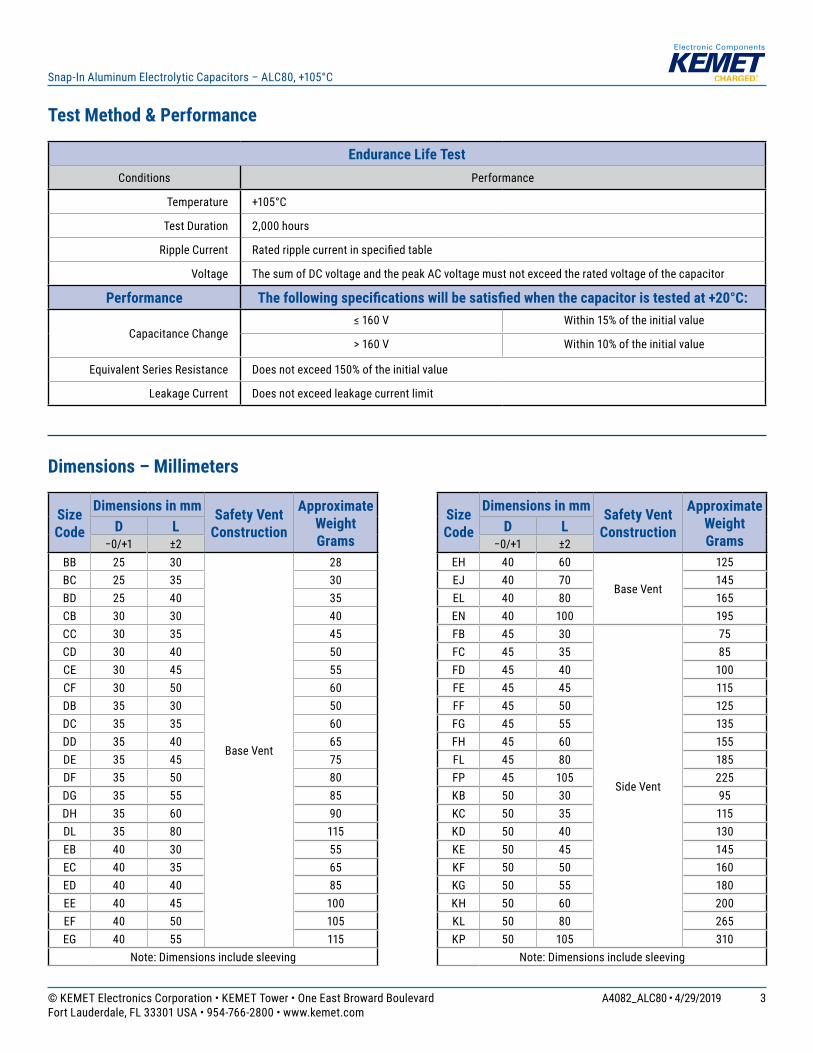
Test Method & Performance
Endurance Life TestConditions Performance
Temperature +105°C
Test Duration 2,000 hours
Ripple Current Rated ripple current in specified table
Voltage The sum of DC voltage and the peak AC voltage must not exceed the rated voltage of the capacitor
Performance The following specifications will be satisfied when the capacitor is tested at +20°C:
Capacitance Change≤ 160 V Within 15% of the initial value
> 160 V Within 10% of the initial value
Equivalent Series Resistance Does not exceed 150% of the initial value
Leakage Current Does not exceed leakage current limit
Dimensions – Millimeters
Size Code
Dimensions in mm Safety Vent Construction
Approximate Weight Grams
D L−0/+1 ±2
BB 25 30
Base Vent
28BC 25 35 30BD 25 40 35CB 30 30 40CC 30 35 45CD 30 40 50CE 30 45 55CF 30 50 60DB 35 30 50DC 35 35 60DD 35 40 65DE 35 45 75DF 35 50 80DG 35 55 85DH 35 60 90DL 35 80 115EB 40 30 55EC 40 35 65ED 40 40 85EE 40 45 100EF 40 50 105EG 40 55 115
Note: Dimensions include sleeving
Size Code
Dimensions in mm Safety Vent Construction
Approximate Weight Grams
D L−0/+1 ±2
EH 40 60
Base Vent
125EJ 40 70 145EL 40 80 165EN 40 100 195FB 45 30
Side Vent
75FC 45 35 85FD 45 40 100FE 45 45 115FF 45 50 125FG 45 55 135FH 45 60 155FL 45 80 185FP 45 105 225KB 50 30 95KC 50 35 115KD 50 40 130KE 50 45 145KF 50 50 160KG 50 55 180KH 50 60 200KL 50 80 265KP 50 105 310
Note: Dimensions include sleeving
© KEMET Electronics Corporation • KEMET Tower • One East Broward Boulevard A4082_ALC80 • 4/29/2019Fort Lauderdale, FL 33301 USA • 954-766-2800 • www.kemet.com
4
Snap-In Aluminum Electrolytic Capacitors – ALC80, +105°C
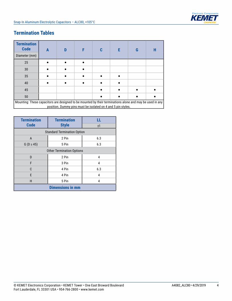
Termination Tables
Termination Code A D F C E G H
Diameter (mm)
25 • • •30 • • •35 • • • • •40 • • • • •45 • • • •50 • • • •
Mounting: These capacitors are designed to be mounted by their terminations alone and may be used in any position. Dummy pins must be isolated on 4 and 5 pin styles.
Termination Code
Termination Style
LL±1
Standard Termination Option
A 2 Pin 6.3
G (D ≥ 45) 5 Pin 6.3
Other Termination Options
D 2 Pin 4
F 3 Pin 4
C 4 Pin 6.3
E 4 Pin 4
H 5 Pin 4
Dimensions in mm
© KEMET Electronics Corporation • KEMET Tower • One East Broward Boulevard A4082_ALC80 • 4/29/2019Fort Lauderdale, FL 33301 USA • 954-766-2800 • www.kemet.com
5
Snap-In Aluminum Electrolytic Capacitors – ALC80, +105°C
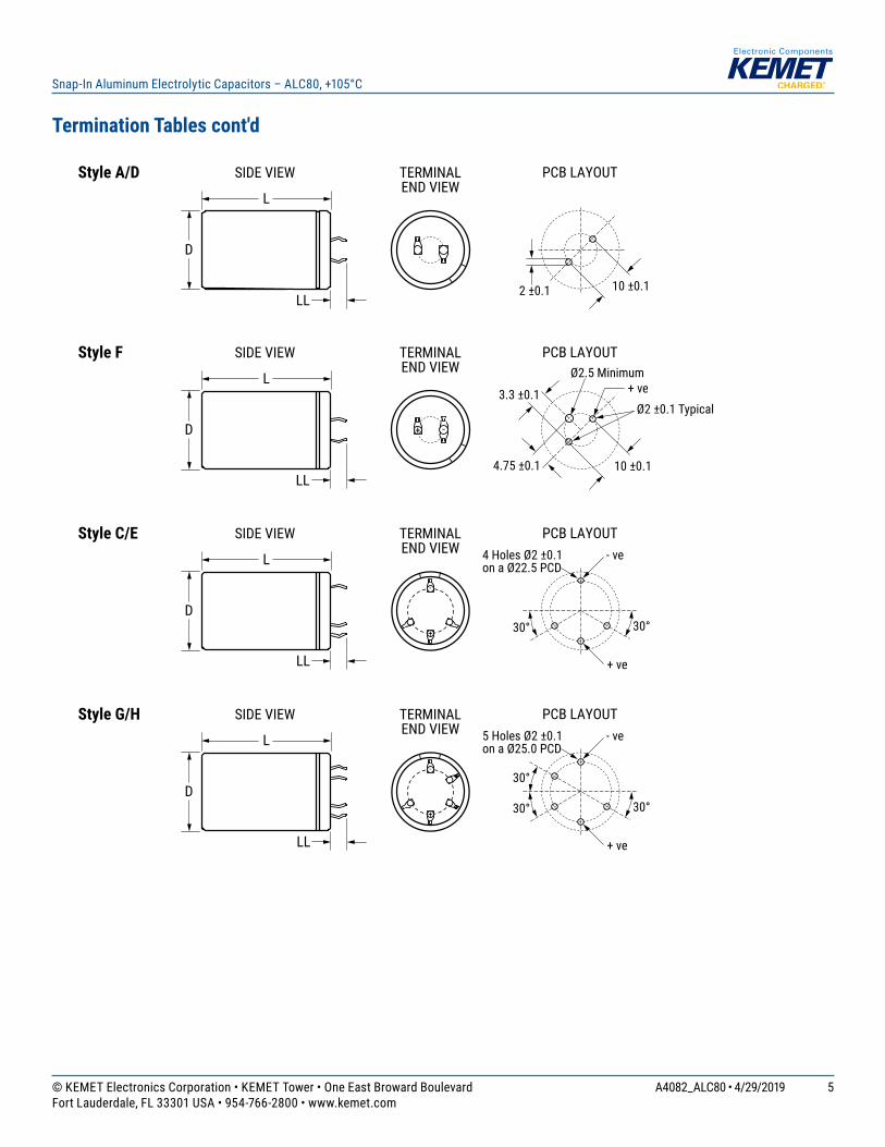
Termination Tables cont'd
L
SIDE VIEW TERMINALEND VIEW
D
PCB LAYOUT
2 ±0.1
Style A/D
L
SIDE VIEW TERMINALEND VIEW
D
PCB LAYOUT
4.75 ±0.1
Style F
L
SIDE VIEW TERMINALEND VIEW
D
PCB LAYOUTStyle C/E
LL10 ±0.1
10 ±0.1
+ -
3.3 ±0.1
Ø2.5 Minimum+ ve
Ø2 ±0.1 Typical
+
-
30°30°
- ve4 Holes Ø2 ±0.1on a Ø22.5 PCD
+ ve
L
SIDE VIEW TERMINALEND VIEW
D
PCB LAYOUTStyle G/H
+
-
30°30°
- ve5 Holes Ø2 ±0.1on a Ø25.0 PCD
+ ve
LL
LL
LL
30°
© KEMET Electronics Corporation • KEMET Tower • One East Broward Boulevard A4082_ALC80 • 4/29/2019Fort Lauderdale, FL 33301 USA • 954-766-2800 • www.kemet.com
6
Snap-In Aluminum Electrolytic Capacitors – ALC80, +105°C
Shelf Life
The capacitance, ESR, and impedance of a capacitor will not change significantly after extended storage periods; however, the leakage current will very slowly increase. KEMET products are particularly stable and allow a shelf life in excess of three years at 40°C. See sectional specification under each product series for specific data.
Re-age (Reforming) Procedure
Apply the rated voltage to the capacitor at room temperature for a period of one hour or until the leakage current has fallen to a steady value below the specified limit. During re-aging, a maximum charging current of twice the specified leakage current or 5 mA (whichever is greater) is suggested.
Reliability
The reliability of a component can be defined as the probability that it will perform satisfactorily under a given set of conditions for a given length of time.
In practice, it is impossible to predict with absolute certainty how any individual component will perform. Therefore, we must utilize probability theory. It is also necessary to clearly define the level of stress involved (e.g., operating voltage, ripple current, temperature, and time.) Finally, the meaning of satisfactory performance must be defined by specifying a set of conditions, which determine the end of life of the component.
KEMET provides an online life calculator that can be used to predict hours of life for a given part number in specific application conditions. This can be found at: https://elc.kemet.com.
End of Life Definition
Catastrophic failure: short circuit, open circuit or safety vent operation
Parametric Failure:• Change in capacitance > ±15%• Leakage current > initial specified limit• ESR > 3X ESR Limit
© KEMET Electronics Corporation • KEMET Tower • One East Broward Boulevard A4082_ALC80 • 4/29/2019Fort Lauderdale, FL 33301 USA • 954-766-2800 • www.kemet.com
7
Snap-In Aluminum Electrolytic Capacitors – ALC80, +105°C
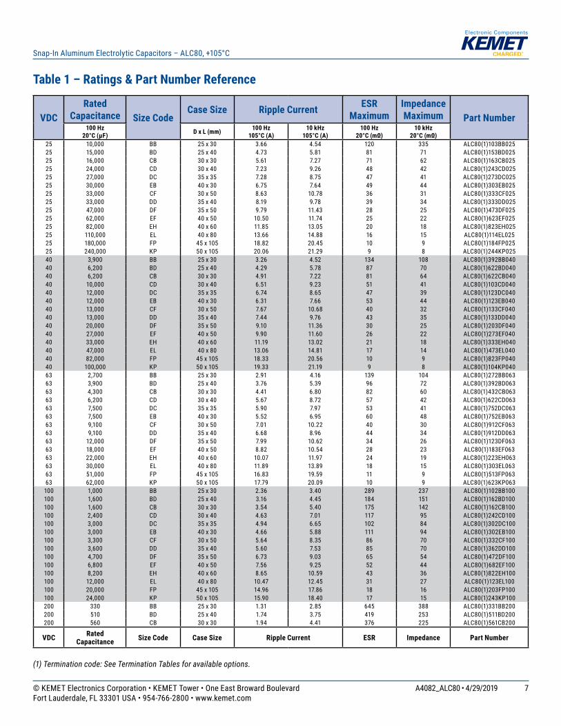
Table 1 – Ratings & Part Number Reference
(1) Termination code: See Termination Tables for available options.
VDCRated
Capacitance Size CodeCase Size Ripple Current ESR
MaximumImpedance Maximum Part Number
100 Hz 20°C (µF) D x L (mm) 100 Hz
105°C (A) 10 kHz
105°C (A)100 Hz
20°C (mΩ)10 kHz
20°C (mΩ)25 10,000 BB 25 x 30 3.66 4.54 120 335 ALC80(1)103BB02525 15,000 BD 25 x 40 4.73 5.81 81 71 ALC80(1)153BD02525 16,000 CB 30 x 30 5.61 7.27 71 62 ALC80(1)163CB02525 24,000 CD 30 x 40 7.23 9.26 48 42 ALC80(1)243CD02525 27,000 DC 35 x 35 7.28 8.75 47 41 ALC80(1)273DC02525 30,000 EB 40 x 30 6.75 7.64 49 44 ALC80(1)303EB02525 33,000 CF 30 x 50 8.63 10.78 36 31 ALC80(1)333CF02525 33,000 DD 35 x 40 8.19 9.78 39 34 ALC80(1)333DD02525 47,000 DF 35 x 50 9.79 11.43 28 25 ALC80(1)473DF02525 62,000 EF 40 x 50 10.50 11.74 25 22 ALC80(1)623EF02525 82,000 EH 40 x 60 11.85 13.05 20 18 ALC80(1)823EH02525 110,000 EL 40 x 80 13.66 14.88 16 15 ALC80(1)114EL02525 180,000 FP 45 x 105 18.82 20.45 10 9 ALC80(1)184FP02525 240,000 KP 50 x 105 20.06 21.29 9 8 ALC80(1)244KP02540 3,900 BB 25 x 30 3.26 4.52 134 108 ALC80(1)392BB04040 6,200 BD 25 x 40 4.29 5.78 87 70 ALC80(1)622BD04040 6,200 CB 30 x 30 4.91 7.22 81 64 ALC80(1)622CB04040 10,000 CD 30 x 40 6.51 9.23 51 41 ALC80(1)103CD04040 12,000 DC 35 x 35 6.74 8.65 47 39 ALC80(1)123DC04040 12,000 EB 40 x 30 6.31 7.66 53 44 ALC80(1)123EB04040 13,000 CF 30 x 50 7.67 10.68 40 32 ALC80(1)133CF04040 13,000 DD 35 x 40 7.44 9.76 43 35 ALC80(1)133DD04040 20,000 DF 35 x 50 9.10 11.36 30 25 ALC80(1)203DF04040 27,000 EF 40 x 50 9.90 11.60 26 22 ALC80(1)273EF04040 33,000 EH 40 x 60 11.19 13.02 21 18 ALC80(1)333EH04040 47,000 EL 40 x 80 13.06 14.81 17 14 ALC80(1)473EL04040 82,000 FP 45 x 105 18.33 20.56 10 9 ALC80(1)823FP04040 100,000 KP 50 x 105 19.33 21.19 9 8 ALC80(1)104KP04063 2,700 BB 25 x 30 2.91 4.16 139 104 ALC80(1)272BB06363 3,900 BD 25 x 40 3.76 5.39 96 72 ALC80(1)392BD06363 4,300 CB 30 x 30 4.41 6.80 82 60 ALC80(1)432CB06363 6,200 CD 30 x 40 5.67 8.72 57 42 ALC80(1)622CD06363 7,500 DC 35 x 35 5.90 7.97 53 41 ALC80(1)752DC06363 7,500 EB 40 x 30 5.52 6.95 60 48 ALC80(1)752EB06363 9,100 CF 30 x 50 7.01 10.22 40 30 ALC80(1)912CF06363 9,100 DD 35 x 40 6.68 8.96 44 34 ALC80(1)912DD06363 12,000 DF 35 x 50 7.99 10.62 34 26 ALC80(1)123DF06363 18,000 EF 40 x 50 8.82 10.54 28 23 ALC80(1)183EF06363 22,000 EH 40 x 60 10.07 11.97 24 19 ALC80(1)223EH06363 30,000 EL 40 x 80 11.89 13.89 18 15 ALC80(1)303EL06363 51,000 FP 45 x 105 16.83 19.59 11 9 ALC80(1)513FP06363 62,000 KP 50 x 105 17.79 20.09 10 9 ALC80(1)623KP063
100 1,000 BB 25 x 30 2.36 3.40 289 237 ALC80(1)102BB100100 1,600 BD 25 x 40 3.16 4.45 184 151 ALC80(1)162BD100100 1,600 CB 30 x 30 3.54 5.40 175 142 ALC80(1)162CB100100 2,400 CD 30 x 40 4.63 7.01 117 95 ALC80(1)242CD100100 3,000 DC 35 x 35 4.94 6.65 102 84 ALC80(1)302DC100100 3,000 EB 40 x 30 4.66 5.88 111 94 ALC80(1)302EB100100 3,300 CF 30 x 50 5.64 8.35 86 70 ALC80(1)332CF100100 3,600 DD 35 x 40 5.60 7.53 85 70 ALC80(1)362DD100100 4,700 DF 35 x 50 6.73 9.03 65 54 ALC80(1)472DF100100 6,800 EF 40 x 50 7.56 9.25 52 44 ALC80(1)682EF100100 8,200 EH 40 x 60 8.65 10.59 43 36 ALC80(1)822EH100100 12,000 EL 40 x 80 10.47 12.45 31 27 ALC80(1)123EL100100 20,000 FP 45 x 105 14.96 17.86 18 16 ALC80(1)203FP100100 24,000 KP 50 x 105 15.90 18.40 17 15 ALC80(1)243KP100200 330 BB 25 x 30 1.31 2.85 645 388 ALC80(1)331BB200200 510 BD 25 x 40 1.74 3.75 419 253 ALC80(1)511BD200200 560 CB 30 x 30 1.94 4.41 376 225 ALC80(1)561CB200
VDC Rated Capacitance Size Code Case Size Ripple Current ESR Impedance Part Number
© KEMET Electronics Corporation • KEMET Tower • One East Broward Boulevard A4082_ALC80 • 4/29/2019Fort Lauderdale, FL 33301 USA • 954-766-2800 • www.kemet.com
8
Snap-In Aluminum Electrolytic Capacitors – ALC80, +105°C
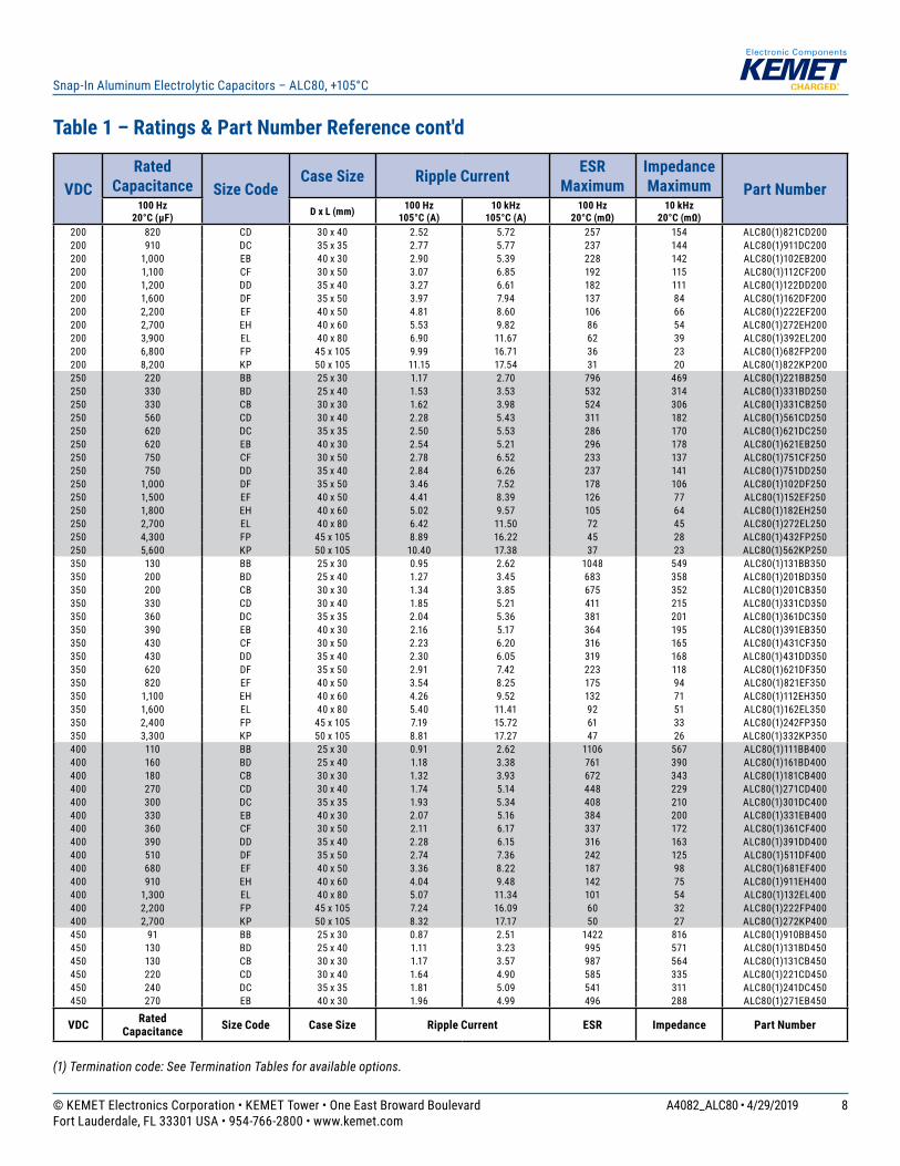
Table 1 – Ratings & Part Number Reference cont'd
(1) Termination code: See Termination Tables for available options.
VDCRated
Capacitance Size CodeCase Size Ripple Current ESR
MaximumImpedance Maximum Part Number
100 Hz 20°C (µF) D x L (mm) 100 Hz
105°C (A) 10 kHz
105°C (A)100 Hz
20°C (mΩ)10 kHz
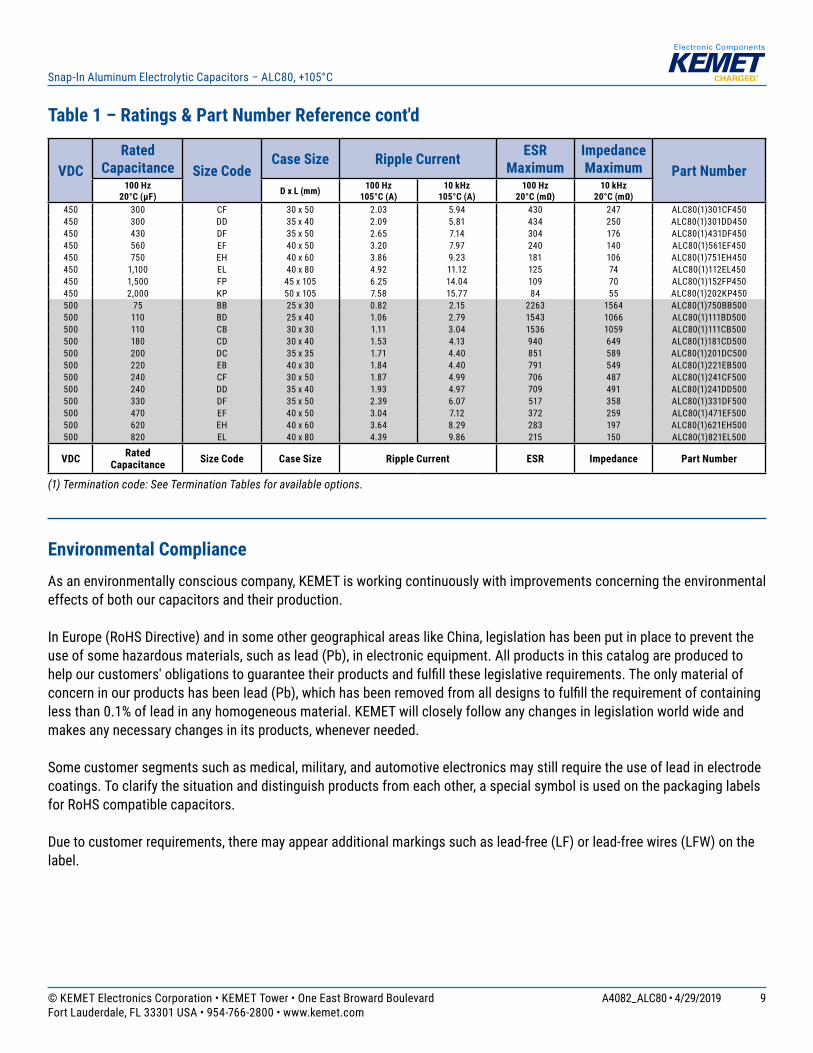
20°C (mΩ)200 820 CD 30 x 40 2.52 5.72 257 154 ALC80(1)821CD200200 910 DC 35 x 35 2.77 5.77 237 144 ALC80(1)911DC200200 1,000 EB 40 x 30 2.90 5.39 228 142 ALC80(1)102EB200200 1,100 CF 30 x 50 3.07 6.85 192 115 ALC80(1)112CF200200 1,200 DD 35 x 40 3.27 6.61 182 111 ALC80(1)122DD200200 1,600 DF 35 x 50 3.97 7.94 137 84 ALC80(1)162DF200200 2,200 EF 40 x 50 4.81 8.60 106 66 ALC80(1)222EF200200 2,700 EH 40 x 60 5.53 9.82 86 54 ALC80(1)272EH200200 3,900 EL 40 x 80 6.90 11.67 62 39 ALC80(1)392EL200200 6,800 FP 45 x 105 9.99 16.71 36 23 ALC80(1)682FP200200 8,200 KP 50 x 105 11.15 17.54 31 20 ALC80(1)822KP200250 220 BB 25 x 30 1.17 2.70 796 469 ALC80(1)221BB250250 330 BD 25 x 40 1.53 3.53 532 314 ALC80(1)331BD250250 330 CB 30 x 30 1.62 3.98 524 306 ALC80(1)331CB250250 560 CD 30 x 40 2.28 5.43 311 182 ALC80(1)561CD250250 620 DC 35 x 35 2.50 5.53 286 170 ALC80(1)621DC250250 620 EB 40 x 30 2.54 5.21 296 178 ALC80(1)621EB250250 750 CF 30 x 50 2.78 6.52 233 137 ALC80(1)751CF250250 750 DD 35 x 40 2.84 6.26 237 141 ALC80(1)751DD250250 1,000 DF 35 x 50 3.46 7.52 178 106 ALC80(1)102DF250250 1,500 EF 40 x 50 4.41 8.39 126 77 ALC80(1)152EF250250 1,800 EH 40 x 60 5.02 9.57 105 64 ALC80(1)182EH250250 2,700 EL 40 x 80 6.42 11.50 72 45 ALC80(1)272EL250250 4,300 FP 45 x 105 8.89 16.22 45 28 ALC80(1)432FP250250 5,600 KP 50 x 105 10.40 17.38 37 23 ALC80(1)562KP250350 130 BB 25 x 30 0.95 2.62 1048 549 ALC80(1)131BB350350 200 BD 25 x 40 1.27 3.45 683 358 ALC80(1)201BD350350 200 CB 30 x 30 1.34 3.85 675 352 ALC80(1)201CB350350 330 CD 30 x 40 1.85 5.21 411 215 ALC80(1)331CD350350 360 DC 35 x 35 2.04 5.36 381 201 ALC80(1)361DC350350 390 EB 40 x 30 2.16 5.17 364 195 ALC80(1)391EB350350 430 CF 30 x 50 2.23 6.20 316 165 ALC80(1)431CF350350 430 DD 35 x 40 2.30 6.05 319 168 ALC80(1)431DD350350 620 DF 35 x 50 2.91 7.42 223 118 ALC80(1)621DF350350 820 EF 40 x 50 3.54 8.25 175 94 ALC80(1)821EF350350 1,100 EH 40 x 60 4.26 9.52 132 71 ALC80(1)112EH350350 1,600 EL 40 x 80 5.40 11.41 92 51 ALC80(1)162EL350350 2,400 FP 45 x 105 7.19 15.72 61 33 ALC80(1)242FP350350 3,300 KP 50 x 105 8.81 17.27 47 26 ALC80(1)332KP350400 110 BB 25 x 30 0.91 2.62 1106 567 ALC80(1)111BB400400 160 BD 25 x 40 1.18 3.38 761 390 ALC80(1)161BD400400 180 CB 30 x 30 1.32 3.93 672 343 ALC80(1)181CB400400 270 CD 30 x 40 1.74 5.14 448 229 ALC80(1)271CD400400 300 DC 35 x 35 1.93 5.34 408 210 ALC80(1)301DC400400 330 EB 40 x 30 2.07 5.16 384 200 ALC80(1)331EB400400 360 CF 30 x 50 2.11 6.17 337 172 ALC80(1)361CF400400 390 DD 35 x 40 2.28 6.15 316 163 ALC80(1)391DD400400 510 DF 35 x 50 2.74 7.36 242 125 ALC80(1)511DF400400 680 EF 40 x 50 3.36 8.22 187 98 ALC80(1)681EF400400 910 EH 40 x 60 4.04 9.48 142 75 ALC80(1)911EH400400 1,300 EL 40 x 80 5.07 11.34 101 54 ALC80(1)132EL400400 2,200 FP 45 x 105 7.24 16.09 60 32 ALC80(1)222FP400400 2,700 KP 50 x 105 8.32 17.17 50 27 ALC80(1)272KP400450 91 BB 25 x 30 0.87 2.51 1422 816 ALC80(1)910BB450450 130 BD 25 x 40 1.11 3.23 995 571 ALC80(1)131BD450450 130 CB 30 x 30 1.17 3.57 987 564 ALC80(1)131CB450450 220 CD 30 x 40 1.64 4.90 585 335 ALC80(1)221CD450450 240 DC 35 x 35 1.81 5.09 541 311 ALC80(1)241DC450450 270 EB 40 x 30 1.96 4.99 496 288 ALC80(1)271EB450
VDC Rated Capacitance Size Code Case Size Ripple Current ESR Impedance Part Number
© KEMET Electronics Corporation • KEMET Tower • One East Broward Boulevard A4082_ALC80 • 4/29/2019Fort Lauderdale, FL 33301 USA • 954-766-2800 • www.kemet.com
9
Snap-In Aluminum Electrolytic Capacitors – ALC80, +105°C
VDCRated
Capacitance Size CodeCase Size Ripple Current ESR
MaximumImpedance Maximum Part Number
100 Hz 20°C (µF) D x L (mm) 100 Hz
105°C (A) 10 kHz
105°C (A)100 Hz
20°C (mΩ)10 kHz
20°C (mΩ)450 300 CF 30 x 50 2.03 5.94 430 247 ALC80(1)301CF450450 300 DD 35 x 40 2.09 5.81 434 250 ALC80(1)301DD450450 430 DF 35 x 50 2.65 7.14 304 176 ALC80(1)431DF450450 560 EF 40 x 50 3.20 7.97 240 140 ALC80(1)561EF450450 750 EH 40 x 60 3.86 9.23 181 106 ALC80(1)751EH450450 1,100 EL 40 x 80 4.92 11.12 125 74 ALC80(1)112EL450450 1,500 FP 45 x 105 6.25 14.04 109 70 ALC80(1)152FP450450 2,000 KP 50 x 105 7.58 15.77 84 55 ALC80(1)202KP450500 75 BB 25 x 30 0.82 2.15 2263 1564 ALC80(1)750BB500500 110 BD 25 x 40 1.06 2.79 1543 1066 ALC80(1)111BD500500 110 CB 30 x 30 1.11 3.04 1536 1059 ALC80(1)111CB500500 180 CD 30 x 40 1.53 4.13 940 649 ALC80(1)181CD500500 200 DC 35 x 35 1.71 4.40 851 589 ALC80(1)201DC500500 220 EB 40 x 30 1.84 4.40 791 549 ALC80(1)221EB500500 240 CF 30 x 50 1.87 4.99 706 487 ALC80(1)241CF500500 240 DD 35 x 40 1.93 4.97 709 491 ALC80(1)241DD500500 330 DF 35 x 50 2.39 6.07 517 358 ALC80(1)331DF500500 470 EF 40 x 50 3.04 7.12 372 259 ALC80(1)471EF500500 620 EH 40 x 60 3.64 8.29 283 197 ALC80(1)621EH500500 820 EL 40 x 80 4.39 9.86 215 150 ALC80(1)821EL500
VDC Rated Capacitance Size Code Case Size Ripple Current ESR Impedance Part Number
Table 1 – Ratings & Part Number Reference cont'd
(1) Termination code: See Termination Tables for available options.
Environmental ComplianceAs an environmentally conscious company, KEMET is working continuously with improvements concerning the environmental effects of both our capacitors and their production.
In Europe (RoHS Directive) and in some other geographical areas like China, legislation has been put in place to prevent the use of some hazardous materials, such as lead (Pb), in electronic equipment. All products in this catalog are produced to help our customers' obligations to guarantee their products and fulfill these legislative requirements. The only material of concern in our products has been lead (Pb), which has been removed from all designs to fulfill the requirement of containing less than 0.1% of lead in any homogeneous material. KEMET will closely follow any changes in legislation world wide and makes any necessary changes in its products, whenever needed.
Some customer segments such as medical, military, and automotive electronics may still require the use of lead in electrode coatings. To clarify the situation and distinguish products from each other, a special symbol is used on the packaging labels for RoHS compatible capacitors.
Due to customer requirements, there may appear additional markings such as lead-free (LF) or lead-free wires (LFW) on the label.
© KEMET Electronics Corporation • KEMET Tower • One East Broward Boulevard A4082_ALC80 • 4/29/2019Fort Lauderdale, FL 33301 USA • 954-766-2800 • www.kemet.com
10
Snap-In Aluminum Electrolytic Capacitors – ALC80, +105°C
Mechanical Data
Polarity and Reversed VoltageAluminium Electrolytic capacitors manufactured for use in DC applications contain an anode foil and a cathode foil. As such, they are polarized devices and must be connected with the +ve to the anode foil and the -ve to the cathode foil. If this were to be reversed then the electrolytic process that took place in forming the oxide layer on the anode would be recreated in trying to form an oxide layer on the cathode. In forming the cathode foil in this way, heat would be generated and gas given off within the capacitor, usually leading to catastrophic failure.
The cathode foil already possesses a thin stabilized oxide layer. This thin oxide layer is equivalent to a forming voltage of approximately 2 V. As a result, the capacitor can withstand a voltage reversal of up to 2 V for short periods. Above this voltage, the formation process will commence. Aluminium Electrolytic capacitors can also be manufactured for use in intermittent AC applications by using two anode foils in place of one anode and one cathode.
Mounting PositionThe capacitor can be mounted upright or inclined to a horizontal position. Special attention for the safety vent coverage, which this ensures that internal gas generated can escape when the pressure reaches a certain value due to overstress or catastrophic failure. All mounting positions must allow the safety vent to work properly.
Insulating Resistance≥ 100 MΩ at 100 VDC across insulating sleeve.
Voltage Proof≥ 3,500 VDC across insulating sleeve.≥ 2,500 VAC across insulating sleeve.
Safety VentFor diameters up to 40 mm, the safety vent for overpressure is featured on the base (opposing end to the terminals), and for diameters 45 mm or higher, the safety vent is featured in the side of the can. This is a weakened area in the bottom of the can that is designed to relieve build-up of internal pressure due to overstress or catastrophic failure.
© KEMET Electronics Corporation • KEMET Tower • One East Broward Boulevard A4082_ALC80 • 4/29/2019Fort Lauderdale, FL 33301 USA • 954-766-2800 • www.kemet.com
11
Snap-In Aluminum Electrolytic Capacitors – ALC80, +105°C
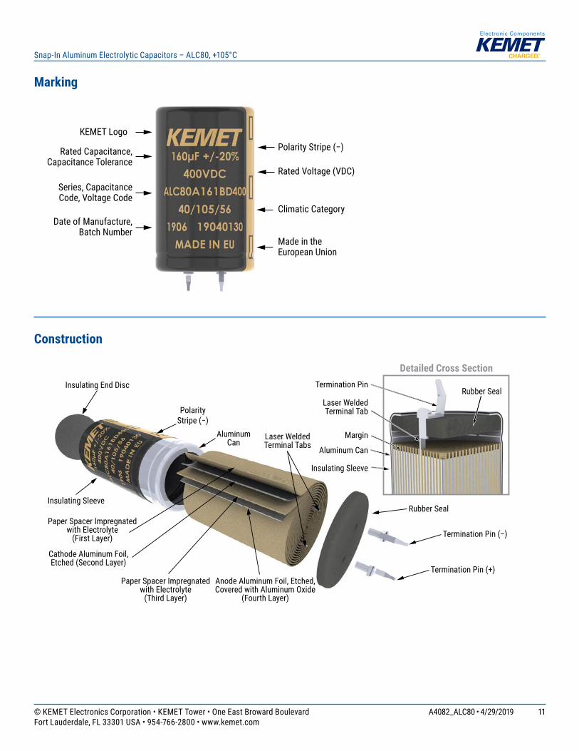
Marking
KEMET Logo
Rated Capacitance, Capacitance Tolerance
Rated Voltage (VDC)
Polarity Stripe (−)
Series, Capacitance Code, Voltage Code
Climatic Category
Made in theEuropean Union
Date of Manufacture, Batch Number
Construction
Detailed Cross Section
Margin
Termination Pin (−)
Rubber Seal
Rubber SealInsulating Sleeve
AluminumCan
Laser Welded Terminal Tabs
Termination Pin
Laser Welded Terminal Tab
Aluminum Can
Insulating Sleeve
Insulating End Disc
Termination Pin (+)
Paper Spacer Impregnatedwith Electrolyte
(First Layer)
Paper Spacer Impregnated with Electrolyte
(Third Layer)
Anode Aluminum Foil, Etched, Covered with Aluminum Oxide
(Fourth Layer)
Cathode Aluminum Foil, Etched (Second Layer)
PolarityStripe (−)

© KEMET Electronics Corporation • KEMET Tower • One East Broward Boulevard A4082_ALC80 • 4/29/2019Fort Lauderdale, FL 33301 USA • 954-766-2800 • www.kemet.com
12
Snap-In Aluminum Electrolytic Capacitors – ALC80, +105°C
Extended cathode
Anode foil
Cathode foil
Tissues
Foil tabs
Aging
Etching
Forming
Winding
Decking
Impregnation
Assembly
Testing
Sleeving
Packing
Construction Data
The manufacturing process begins with the anode foil being electrochemically etched to increase the surface area and then “formed” to produce the aluminum oxide layer. Both the anode and cathode foils are then interleaved with absorbent paper and wound into a cylinder. During the winding process, aluminum tabs are attached to each foil to provide the electrical contact.
The deck, complete with terminals, is attached to the tabs and then folded down to rest on top of the winding. The complete winding is impregnated with electrolyte before being housed in a suitable container, usually an aluminum can, and sealed. Throughout the process, all materials inside the housing must be maintained at the highest purity and be compatible with the electrolyte.
Each capacitor is aged and tested before being sleeved and packed. The purpose of aging is to repair any damage in the oxide layer and thus reduce the leakage current to a very low level. Aging is normally carried out at the rated temperature of the capacitor and is accomplished by applying voltage to the device while carefully controlling the supply current. The process may take several hours to complete.
Damage to the oxide layer can occur due to variety of reasons: • Slitting of the anode foil after forming • Attaching the tabs to the anode foil • Minor mechanical damage caused during winding
A sample from each batch is taken by the quality department after completion of the production process. This sample size is controlled by the use of recognized sampling tables defi ned in BS 6001.
The following tests are applied and may be varied at the request of the customer. In this case the batch, or special procedure, will determine the course of action.
Electrical: • Leakage current • Capacitance • ESR • Impedance • Tan Delta
Mechanical/Visual: • Overall dimensions • Torque test of mounting stud • Print detail • Box labels • Packaging, including packed
quantity
© KEMET Electronics Corporation • KEMET Tower • One East Broward Boulevard A4082_ALC80 • 4/29/2019Fort Lauderdale, FL 33301 USA • 954-766-2800 • www.kemet.com
13
Snap-In Aluminum Electrolytic Capacitors – ALC80, +105°C
KEMET Electronics Corporation Sales Offi ces
For a complete list of our global sales offi ces, please visit www.kemet.com/sales.
DisclaimerAll product specifi cations, statements, information and data (collectively, the “Information”) in this datasheet are subject to change. The customer is responsible for checking and verifying the extent to which the Information contained in this publication is applicable to an order at the time the order is placed. All Information given herein is believed to be accurate and reliable, but it is presented without guarantee, warranty, or responsibility of any kind, expressed or implied.
Statements of suitability for certain applications are based on KEMET Electronics Corporation’s (“KEMET”) knowledge of typical operating conditions for such applications, but are not intended to constitute – and KEMET specifi cally disclaims – any warranty concerning suitability for a specifi c customer application or use. The Information is intended for use only by customers who have the requisite experience and capability to determine the correct products for their application. Any technical advice inferred from this Information or otherwise provided by KEMET with reference to the use of KEMET’s products is given gratis, and KEMET assumesno obligation or liability for the advice given or results obtained.
Although KEMET designs and manufactures its products to the most stringent quality and safety standards, given the current state of the art, isolated component failures may still occur. Accordingly, customer applications which require a high degree of reliability or safety should employ suitable designs or other safeguards (such as installation of protective circuitry or redundancies) in order to ensure that the failure of an electrical component does not result in a risk of personal injuryor property damage.
Although all product–related warnings, cautions and notes must be observed, the customer should not assume that all safety measures are indicted or that other measures may not be required.
KEMET is a registered trademark of KEMET Electronics Corporation.