Embed Size (px)
Citation preview
snick
snack
CPSC 121: Models of Computation2009 Winter Term 1
Sequential Circuits (“Mealy Machines”)
Steve Wolfman, based on notes by Patrice Belleville and others
1
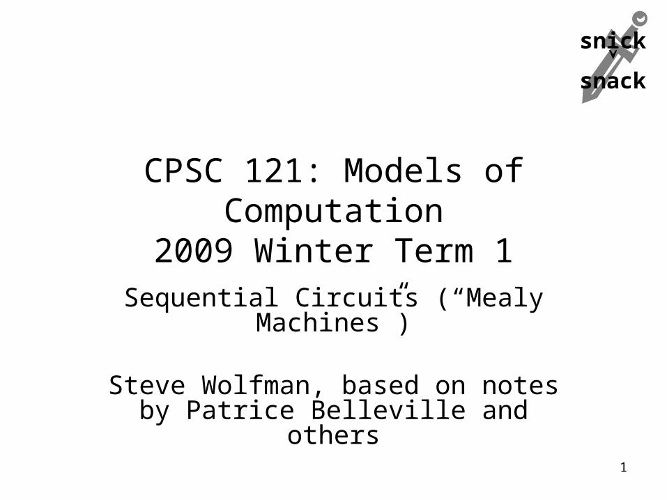
Outline
• Prereqs, Learning Goals, and !Quiz Notes
• Problems and Discussion– A Pushbutton Light Switch– Memory and Events: D Latches & Flip-Flops– General Implementation of DFAs
(with a more complex DFA as an example)– How Powerful are DFAs?
• Next Lecture Notes
2
Lecture Prerequisites
Read Section 12.2 pages 745-747 and “Designing a Finite Automaton” on 752-754 (skipping part b of the examples). We’ll reread and revisit this later; focus on getting a strong intuitive sense of how DFAs work.
Solve problems like Exercise Set 12.2 #1, #12a-c, #13a-c, and #14-19a.
Complete the open-book, untimed quiz on Vista that was due before class.
3
Learning Goals: “Pre-Class”
We are mostly departing from the readings for next class to talk about a new kind of circuit on our way to a full computer: sequential circuits.
The pre-class goals are to be able to:– Trace the operation of a deterministic finite-state
automaton (represented as a diagram) on an input, including indicating whether the DFA accepts or rejects the input.
– Deduce the language accepted by a simple DFA after working through multiple example inputs.
4
Learning Goals: In-Class
By the end of this unit, you should be able to:– Translate a DFA into a sequential circuit that
implements the DFA.– Explain how and why each part of the
resulting circuit works.
5
Where We Are inThe Big Stories
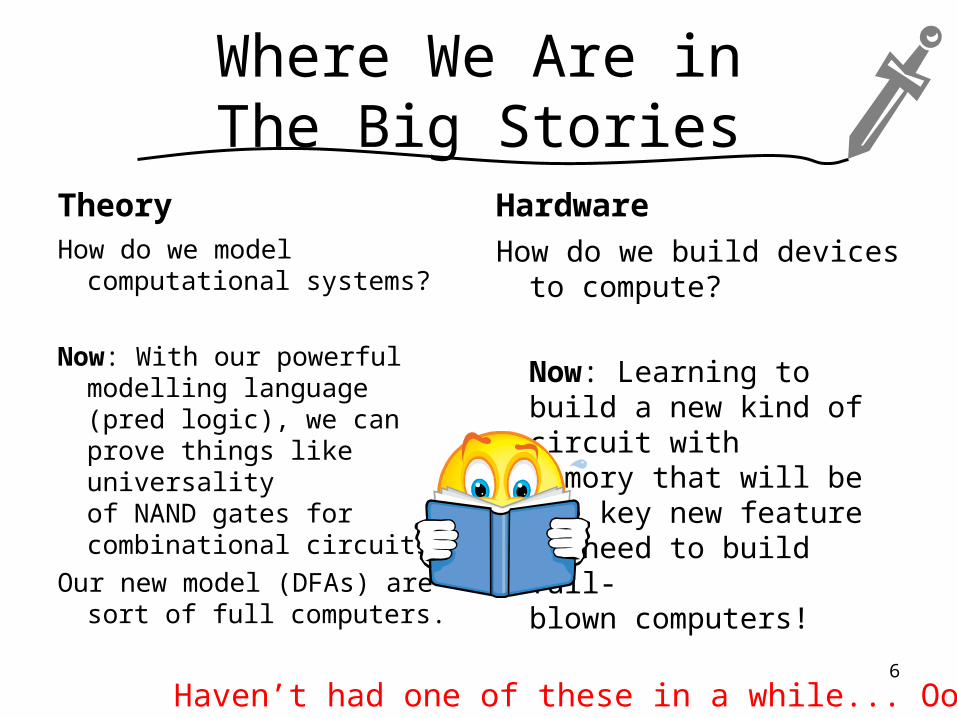
Theory
How do we model computational systems?
Now: With our powerful modelling language (pred logic), we can prove things like universality of NAND gates for combinational circuits.
Our new model (DFAs) are sort of full computers.
Hardware
How do we build devices to compute?
Now: Learning to build a new kind of circuit with
memory that will be the key new feature we need to build full-blown computers!
6
Haven’t had one of these in a while... Oops!
Outline
• Prereqs, Learning Goals, and !Quiz Notes
• Problems and Discussion– A Pushbutton Light Switch– Memory and Events: D Latches & Flip-Flops– General Implementation of DFAs
(with a more complex DFA as an example)– How Powerful are DFAs?
• Next Lecture Notes
7
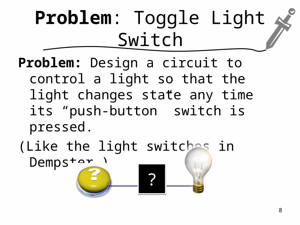
Problem: Toggle Light Switch
Problem: Design a circuit to control a light so that the light changes state any time its “push-button” switch is pressed.
(Like the light switches in Dempster.)
??
8
Concept Q: Toggle Switch
How many gates does the circuit take?
a.One
b.Two
c.Three
d.None of these (b/c it’s a different number)
e.None of these (b/c it can’t be done)
??
9
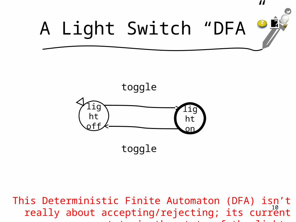
A Light Switch “DFA”
light off
light on
toggle
toggle
This Deterministic Finite Automaton (DFA) isn’t really about accepting/rejecting; its current state is the state of the light.
??
10
Outline
• Prereqs, Learning Goals, and !Quiz Notes
• Problems and Discussion– A Pushbutton Light Switch– Memory and Events: D Latches & Flip-Flops– General Implementation of DFAs
(with a more complex DFA as an example)– How Powerful are DFAs?
• Next Lecture Notes
11
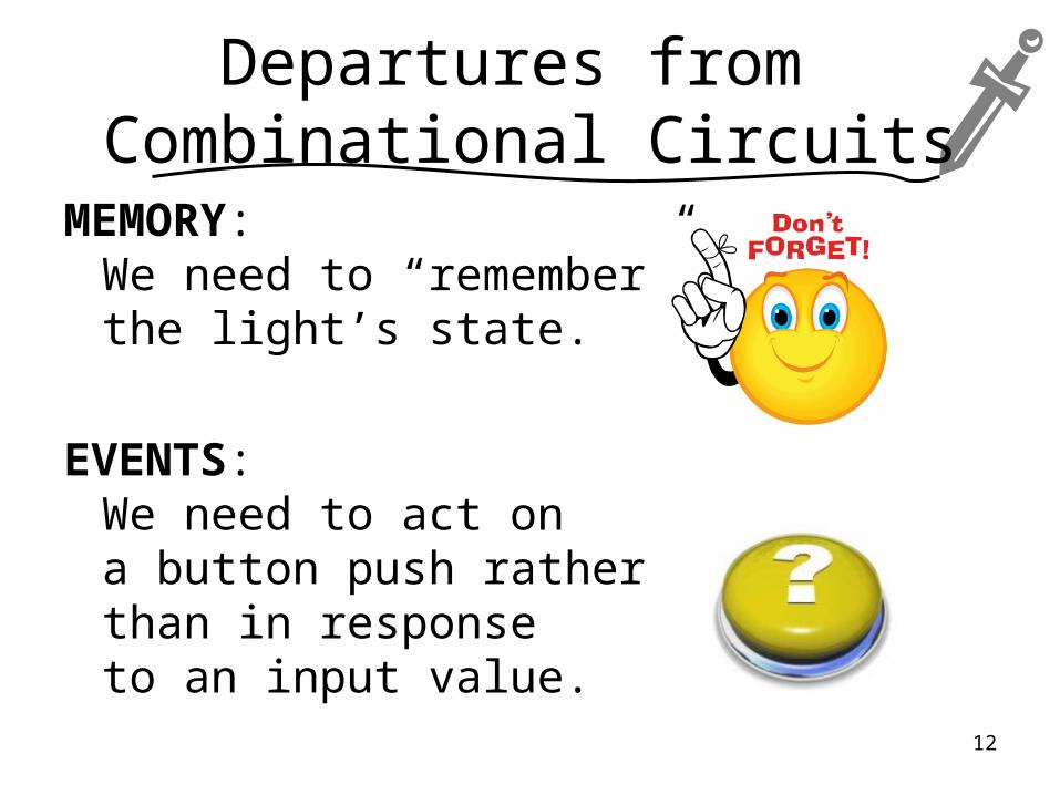
Departures from Combinational Circuits
MEMORY:We need to “remember” the light’s state.
EVENTS:We need to act on a button push rather than in response to an input value.
12
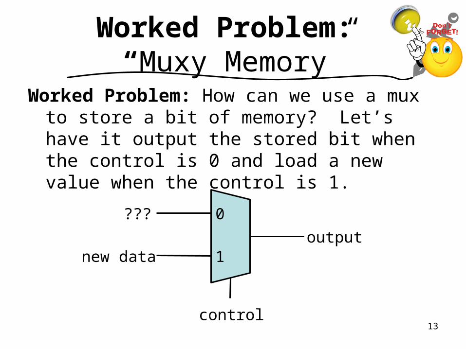
Worked Problem: “Muxy Memory”
Worked Problem: How can we use a mux to store a bit of memory? Let’s have it output the stored bit when the control is 0 and load a new value when the control is 1.
0
1output
???
new data
control13
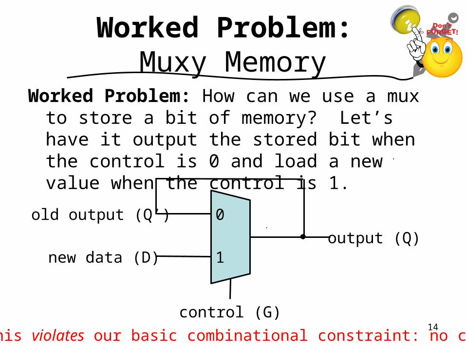
Worked Problem: Muxy Memory
Worked Problem: How can we use a mux to store a bit of memory? Let’s have it output the stored bit when the control is 0 and load a new value when the control is 1.
0
1output (Q)
old output (Q’)
new data (D)
control (G)
This violates our basic combinational constraint: no cycles.14
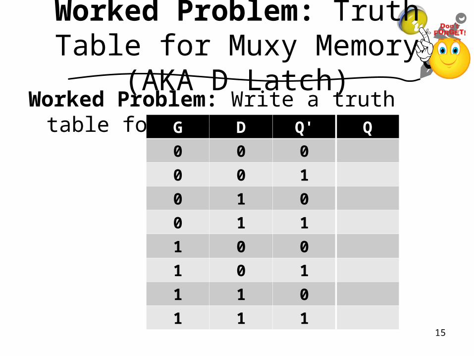
Worked Problem: Truth Table for Muxy Memory (AKA D
Latch)Worked Problem: Write a truth table for the
D Latch. G D Q' Q
0 0 0
0 0 1
0 1 0
0 1 1
1 0 0
1 0 1
1 1 0
1 1 115
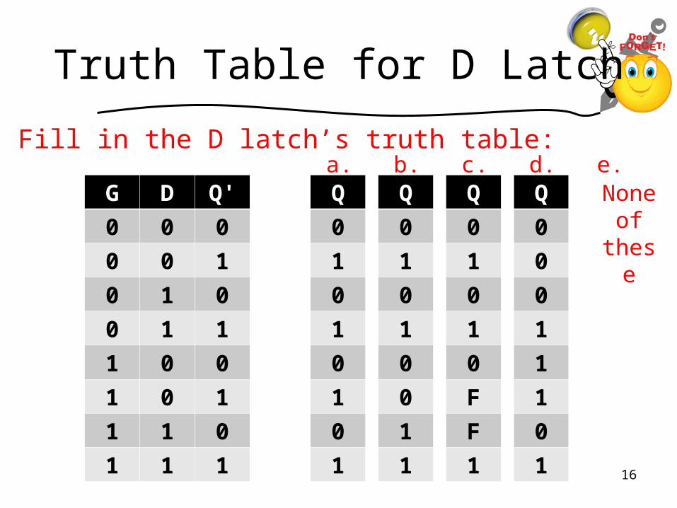
Truth Table for D Latch
Fill in the D latch’s truth table:
G D Q'
0 0 0
0 0 1
0 1 0
0 1 1
1 0 0
1 0 1
1 1 0
1 1 1
a. b. c. d. e.Q
0
1
0
1
0
1
0
1
Q
0
1
0
1
0
0
1
1
Q
0
1
0
1
0
F
F
1
Q
0
0
0
1
1
1
0
1
None of
these
16
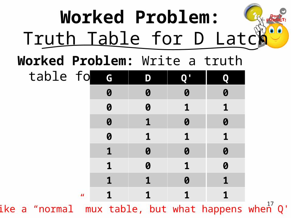
Worked Problem: Truth Table for D Latch
Worked Problem: Write a truth table for the D Latch. G D Q' Q
0 0 0 0
0 0 1 1
0 1 0 0
0 1 1 1
1 0 0 0
1 0 1 0
1 1 0 1
1 1 1 1
Like a “normal” mux table, but what happens when Q' Q?17
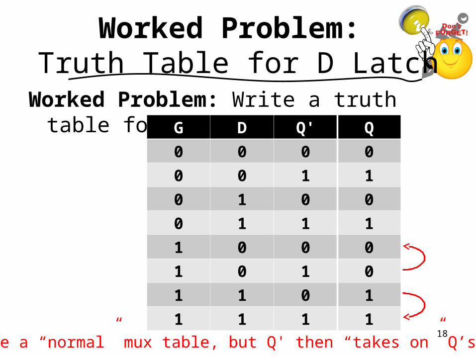
Worked Problem: Truth Table for D Latch
Worked Problem: Write a truth table for the D Latch. G D Q' Q
0 0 0 0
0 0 1 1
0 1 0 0
0 1 1 1
1 0 0 0
1 0 1 0
1 1 0 1
1 1 1 1
Like a “normal” mux table, but Q' then “takes on” Q’s value.18
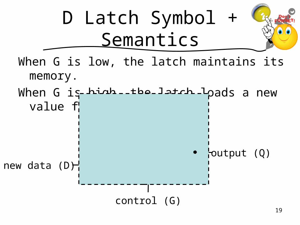
D Latch Symbol + Semantics
When G is low, the latch maintains its memory.
When G is high, the latch loads a new value from D.
0
1output (Q)
old output (Q’)
new data (D)
control (G)19
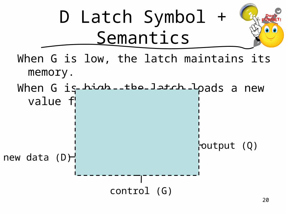
D Latch Symbol + Semantics
When G is low, the latch maintains its memory.
When G is high, the latch loads a new value from D.
0
1output (Q)
old output (Q’)
new data (D)
control (G)20
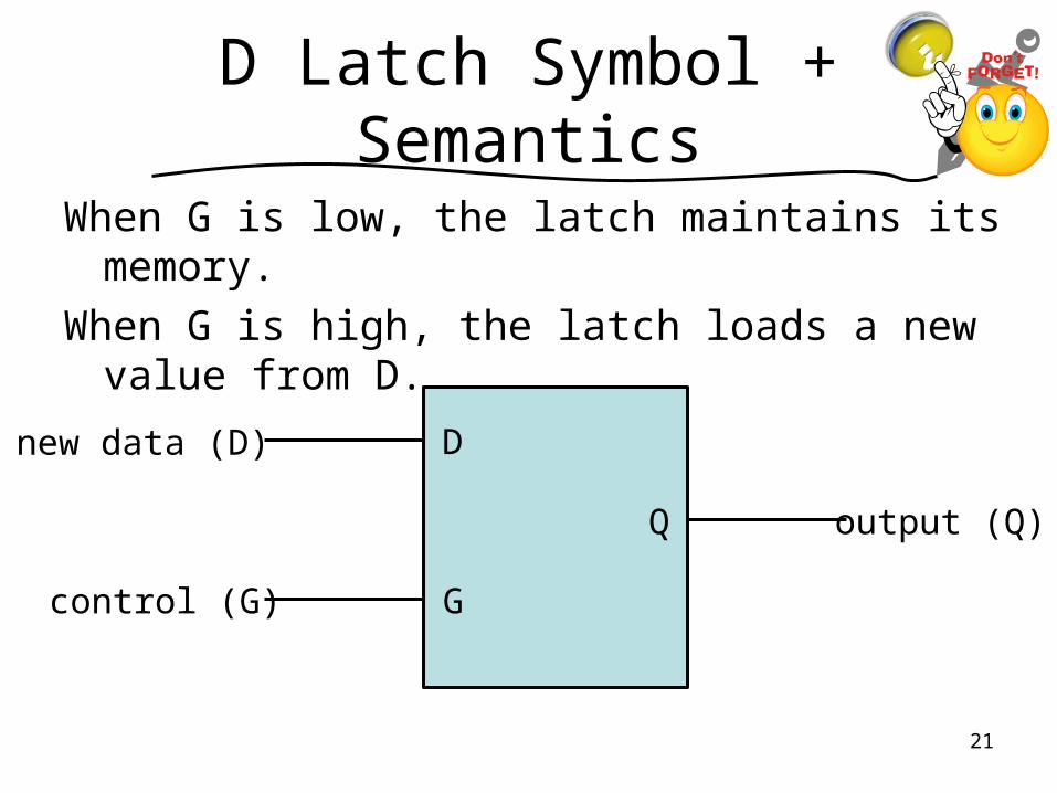
D Latch Symbol + Semantics
When G is low, the latch maintains its memory.
When G is high, the latch loads a new value from D.
output (Q)
new data (D)
control (G)
D
G
Q
21
Hold On!!
Why does the D Latch have two inputs and one output when the mux inside has THREE inputs and one output?
a. The D Latch is broken as is; it should have three inputs.
b. A circuit can always ignore one of its inputs.
c. One of the inputs is always true.
d. One of the inputs is always false.
e. None of these (but the D Latch is not broken as is).
22
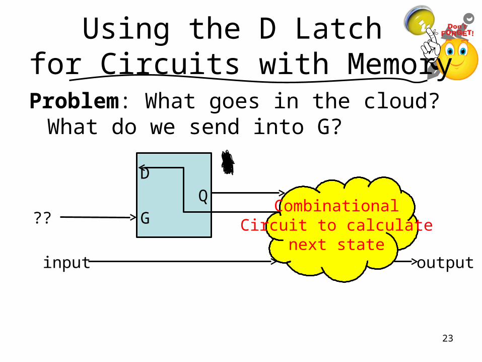
Using the D Latch for Circuits with Memory
Problem: What goes in the cloud? What do we send into G?
D
GQ
CombinationalCircuit to calculate
next stateinput output
??
23
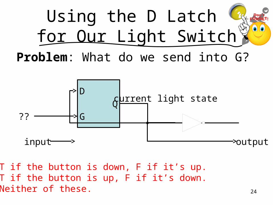
Using the D Latch for Our Light Switch
Problem: What do we send into G?
D
GQ
input output
??
current light state
a. T if the button is down, F if it’s up.b. T if the button is up, F if it’s down.c. Neither of these. 24

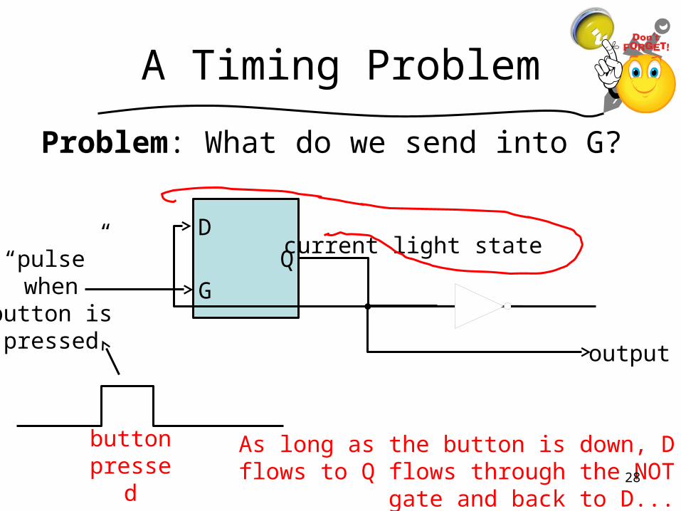
A Timing Problem
Problem: What do we send into G?
D
GQ
output
“pulse” when
button is pressed
current light state
button pressed
As long as the button is down, D flows to Q flows through the NOT gate and back to D...
which is bad!25
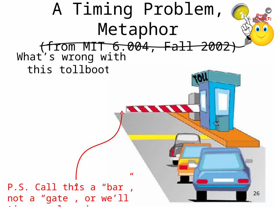
A Timing Problem, Metaphor(from MIT 6.004, Fall 2002)
What’s wrong with this tollbooth?
P.S. Call this a “bar”, not a “gate”, or we’ll tie ourselves in (k)nots.
26
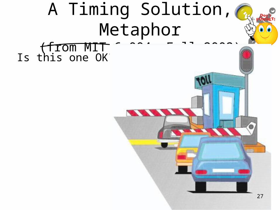
A Timing Solution, Metaphor(from MIT 6.004, Fall 2002)
Is this one OK?
27
A Timing Problem
Problem: What do we send into G?
D
GQ
output
“pulse” when
button is pressed
current light state
button pressed
As long as the button is down, D flows to Q flows through the NOT gate and back to D...
which is bad!28
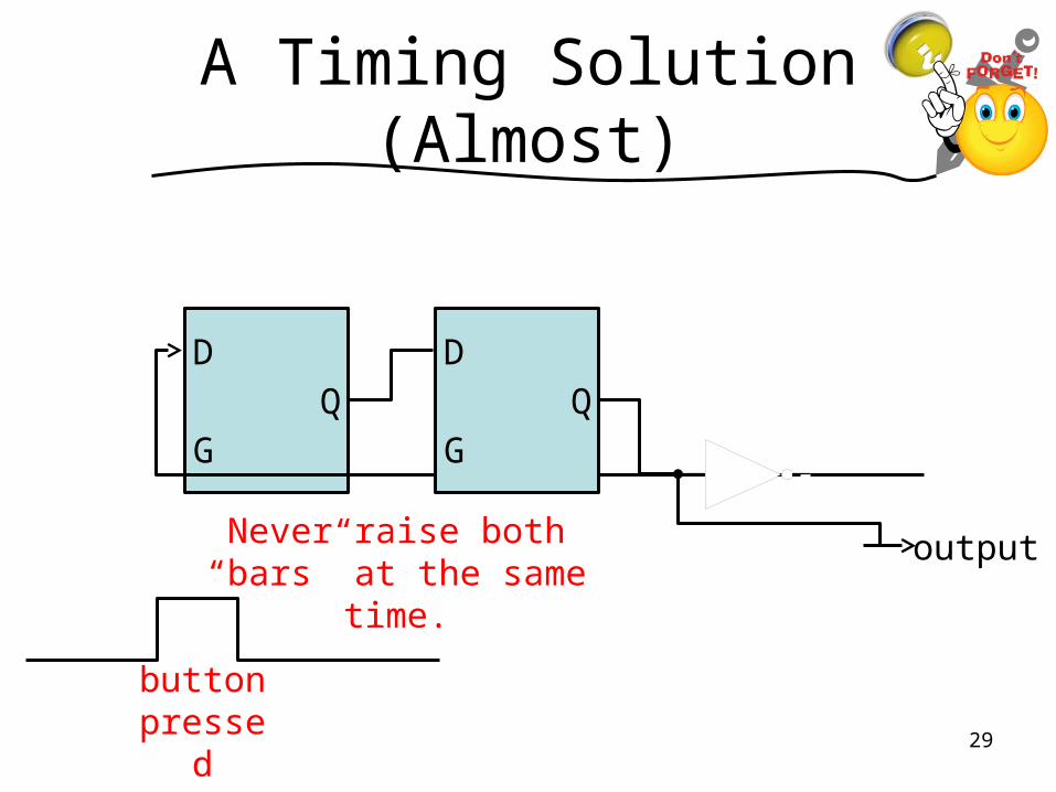
A Timing Solution (Almost)
D
GQ
output
button pressed
D
GQ
Never raise both “bars” at the same time.
29
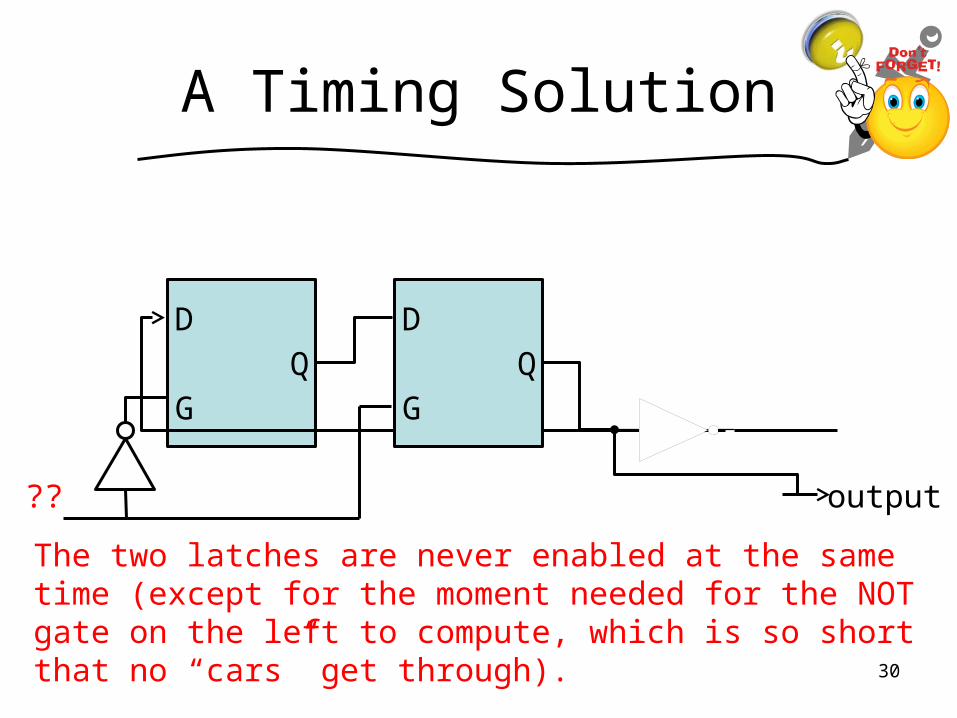
A Timing Solution
D
GQ
output
D
GQ
??
The two latches are never enabled at the same time (except for the moment needed for the NOT gate on the left to compute, which is so short that no “cars” get through).
30
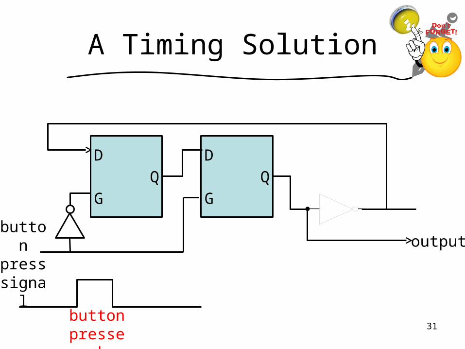
A Timing Solution
D
GQ
output
D
GQ
button pressed
button press signal
31
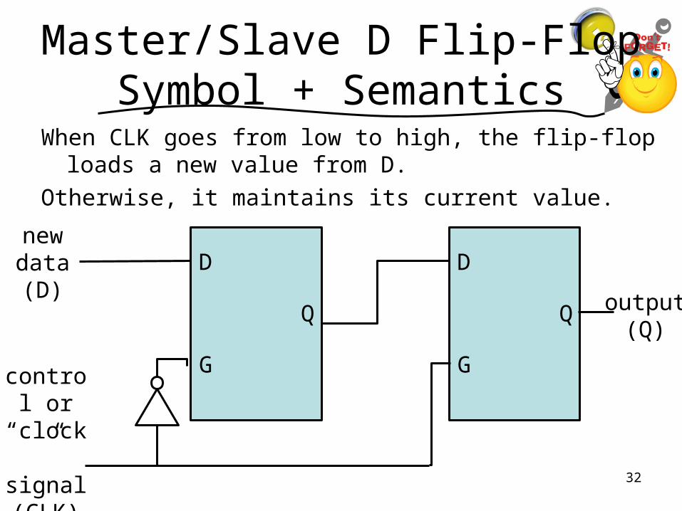
Master/Slave D Flip-Flop Symbol + Semantics
When CLK goes from low to high, the flip-flop loads a new value from D.
Otherwise, it maintains its current value.
output (Q)
new data (D)
control or
“clock” signal (CLK)
D
G
Q
D
G
Q
32
Master/Slave D Flip-Flop Symbol + Semantics
When CLK goes from low to high, the flip-flop loads a new value from D.
Otherwise, it maintains its current value.
output (Q)
new data (D)
control or
“clock” signal (CLK)
D
G
Q
D
G
Q
33

Master/Slave D Flip-Flop Symbol + Semantics
When CLK goes from low to high, the flip-flop loads a new value from D.
Otherwise, it maintains its current value.
output (Q)
new data (D)
control or
“clock” signal (CLK)
D
G
Q
D
G
Q
34
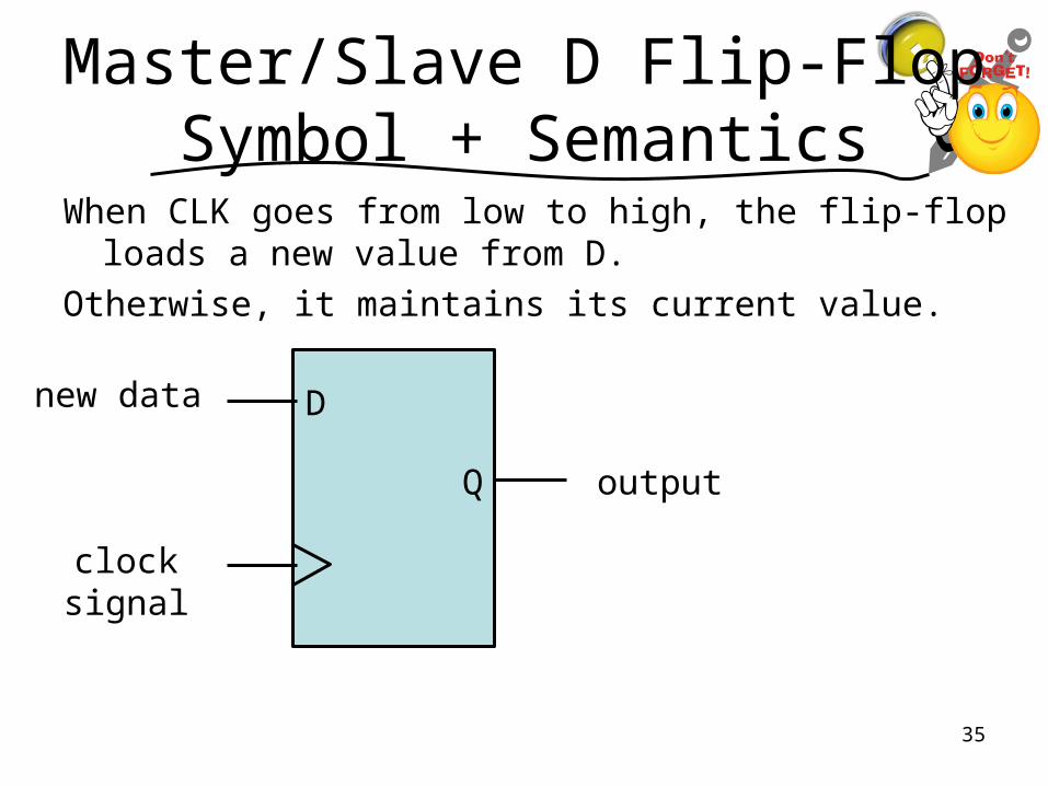
Master/Slave D Flip-Flop Symbol + Semantics
When CLK goes from low to high, the flip-flop loads a new value from D.
Otherwise, it maintains its current value.
new data
clock signal
D
Q output
35
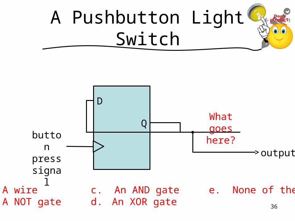
A Pushbutton Light Switch
output
button press signal
D
QWhat goes here?
a. A wire c. An AND gate e. None of these.b. A NOT gate d. An XOR gate
36
Outline
• Prereqs, Learning Goals, and !Quiz Notes
• Problems and Discussion– A Pushbutton Light Switch– Memory and Events: D Latches & Flip-Flops– General Implementation of DFAs
(with a more complex DFA as an example)– How Powerful are DFAs?
• Next Lecture Notes
37
“Mealy Machines” DFAs whose state matters
A “Mealy Machine” is a DFA that’s not about accepting or rejecting but about outputting values as it transitions.
Its output can depend on its state and its input.
Let’s work with a specific example...
38
Branch Prediction Machine
Modern computers “pre-execute” instructions... but to pre-execute an “if” (AKA branch), they have to guess whether the then or else branch is executed.
Here’s one reasonable way to guess: whatever the last branch did, the next one will, too. (Why? Think loops!)
It’s nice to build some “inertia” into this so it won’t flip its guess at the first failure...
39
Implementing the Branch Predictor
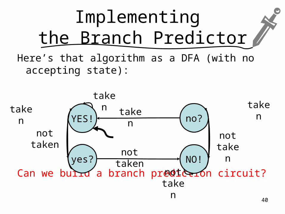
Here’s that algorithm as a DFA (with no accepting state):
Can we build a branch prediction circuit?
YES!
yes?
no?
NO!
nottaken
taken
nottaken
taken
nottaken
takentaken
not taken
40
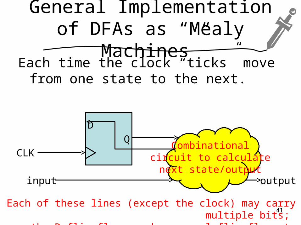
General Implementation of DFAs as “Mealy Machines”
Each time the clock “ticks” move from one state to the next.
D
QCombinational
circuit to calculatenext state/output
input output
CLK
Each of these lines (except the clock) may carry multiple bits; the D flip-flop may be several flip-flops to store several bits.
41
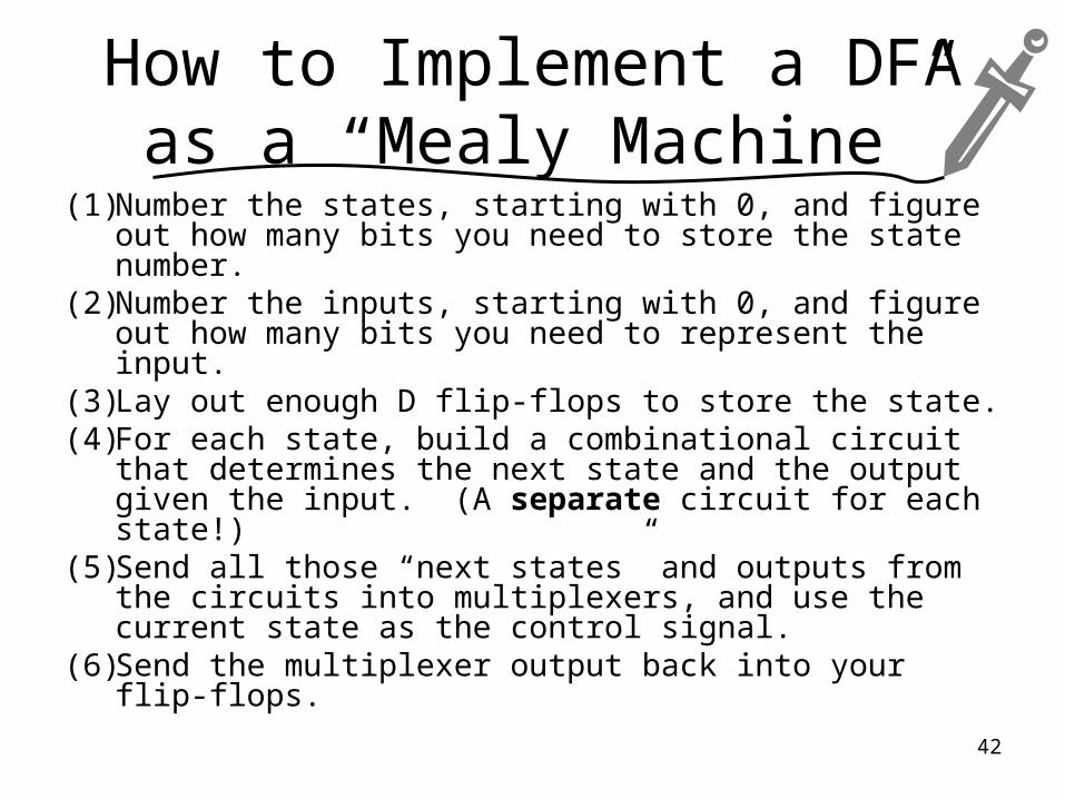
How to Implement a DFA as a “Mealy Machine”
(1) Number the states, starting with 0, and figure out how many bits you need to store the state number.
(2) Number the inputs, starting with 0, and figure out how many bits you need to represent the input.
(3) Lay out enough D flip-flops to store the state.(4) For each state, build a combinational circuit that
determines the next state and the output given the input. (A separate circuit for each state!)
(5) Send all those “next states” and outputs from the circuits into multiplexers, and use the current state as the control signal.
(6) Send the multiplexer output back into your flip-flops.
42
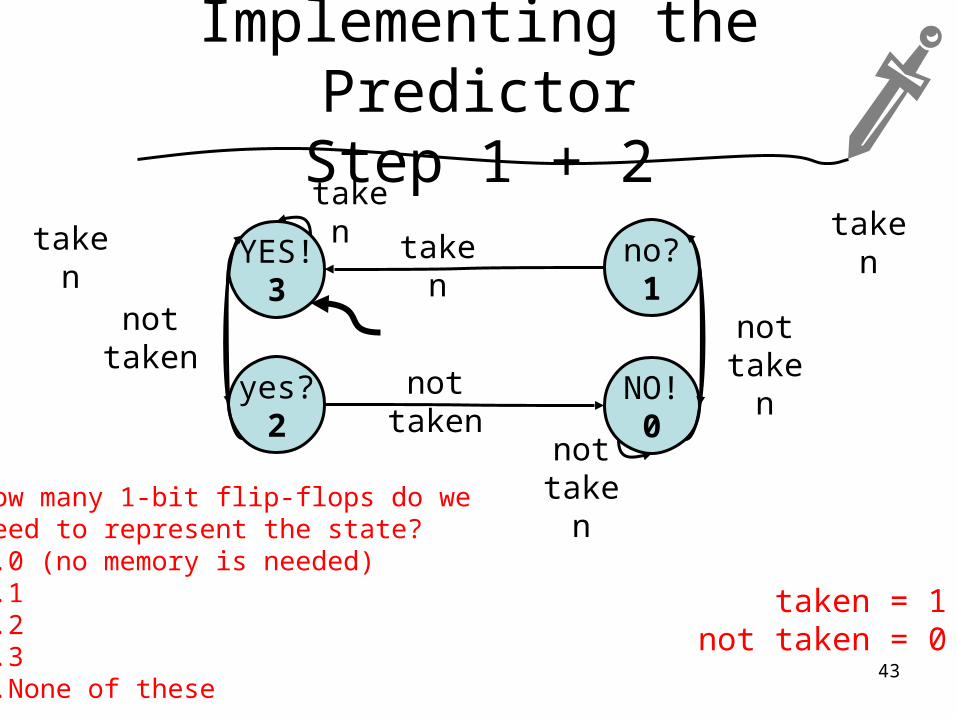
Implementing the PredictorStep 1 + 2
YES!3
yes?2
no?1
NO!0
nottaken
taken
nottaken
taken
nottaken
takentaken
not takenHow many 1-bit flip-flops do we
need to represent the state?a.0 (no memory is needed)b.1c.2d.3e.None of these
taken = 1not taken = 0
43
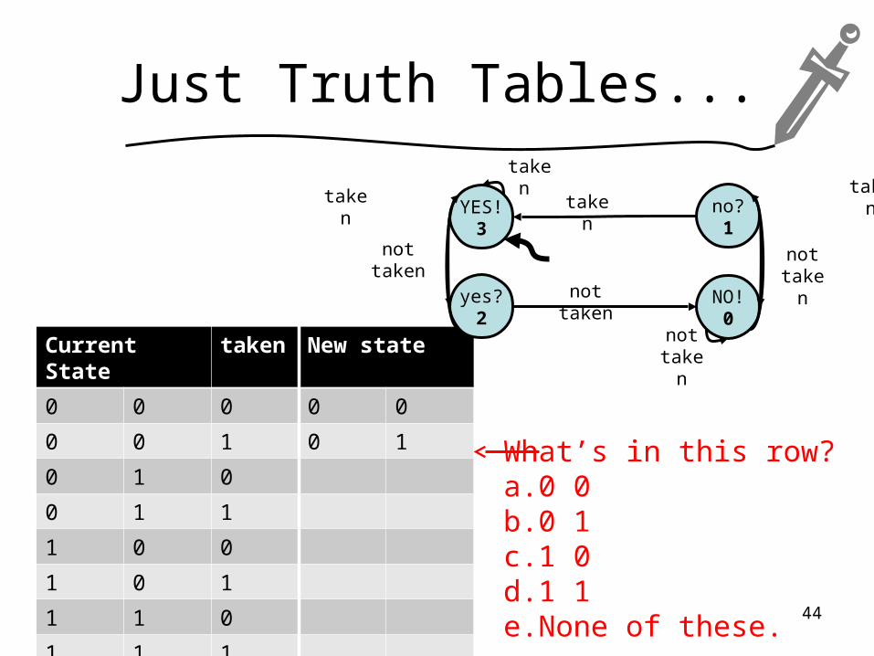
Just Truth Tables...
Current State taken New state
0 0 0 0 0
0 0 1 0 1
0 1 0
0 1 1
1 0 0
1 0 1
1 1 0
1 1 1
YES!3
yes?2
no?1
NO!0
nottaken
taken
nottaken
taken
nottaken
takentaken
not taken
What’s in this row?a.0 0b.0 1c.1 0d.1 1e.None of these.
44
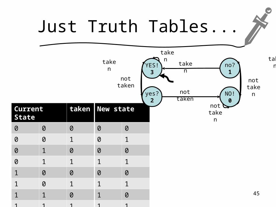
Just Truth Tables...
Current State taken New state
0 0 0 0 0
0 0 1 0 1
0 1 0 0 0
0 1 1 1 1
1 0 0 0 0
1 0 1 1 1
1 1 0 1 0
1 1 1 1 1
YES!3
yes?2
no?1
NO!0
nottaken
taken
nottaken
taken
nottaken
takentaken
not taken
45
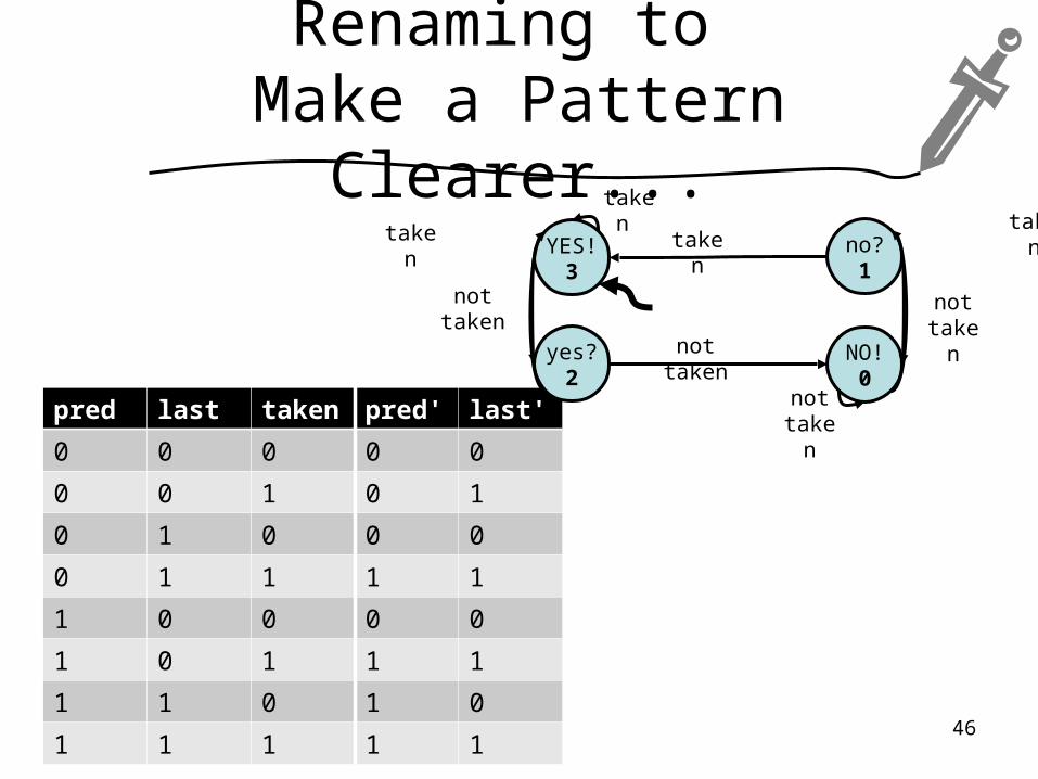
Renaming to Make a Pattern Clearer...
pred last taken pred' last'
0 0 0 0 0
0 0 1 0 1
0 1 0 0 0
0 1 1 1 1
1 0 0 0 0
1 0 1 1 1
1 1 0 1 0
1 1 1 1 1
YES!3
yes?2
no?1
NO!0
nottaken
taken
nottaken
taken
nottaken
takentaken
not taken
46
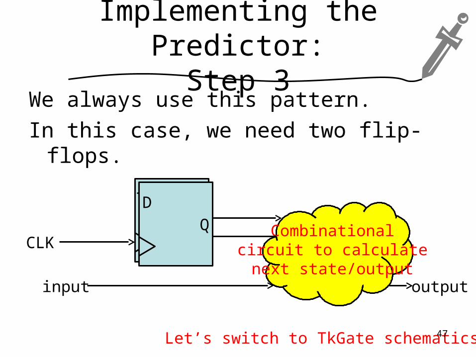
Implementing the Predictor:Step 3
We always use this pattern.
In this case, we need two flip-flops.
D
QCombinational
circuit to calculatenext state/output
input output
CLK
D
Q
Let’s switch to TkGate schematics...47
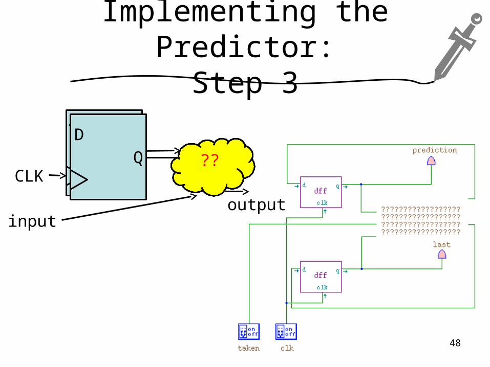
Implementing the Predictor:Step 3
D
Q ??
inputoutput
CLK
D
Q
48
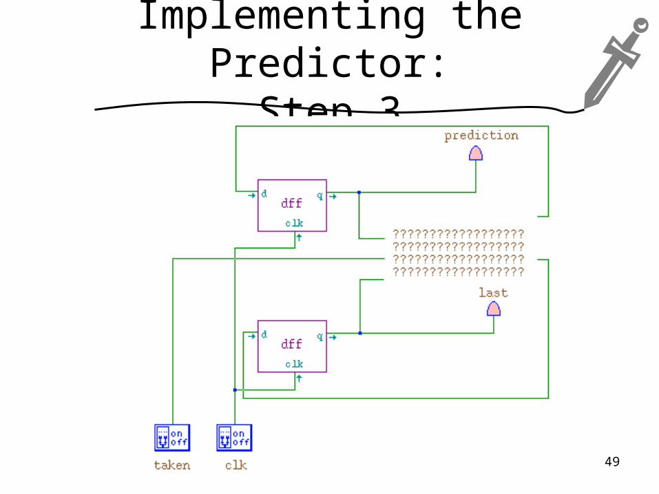
Implementing the Predictor:Step 3
49
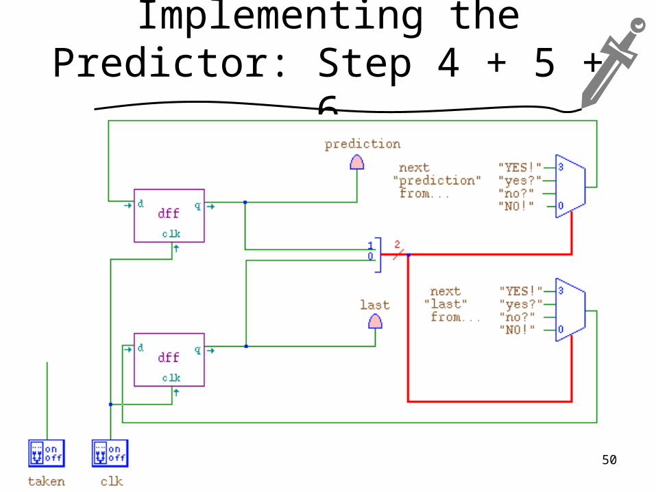
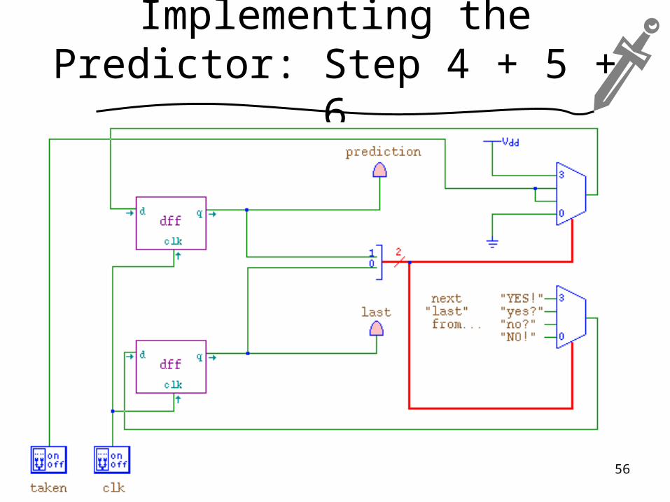
Implementing the Predictor: Step 4 + 5 + 6
50
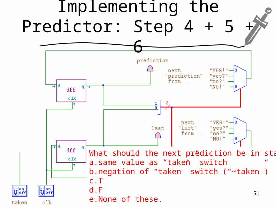
Implementing the Predictor: Step 4 + 5 + 6
What should the next prediction be in state 0?a.same value as “taken” switchb.negation of “taken” switch (“~taken”)c.Td.Fe.None of these.
51

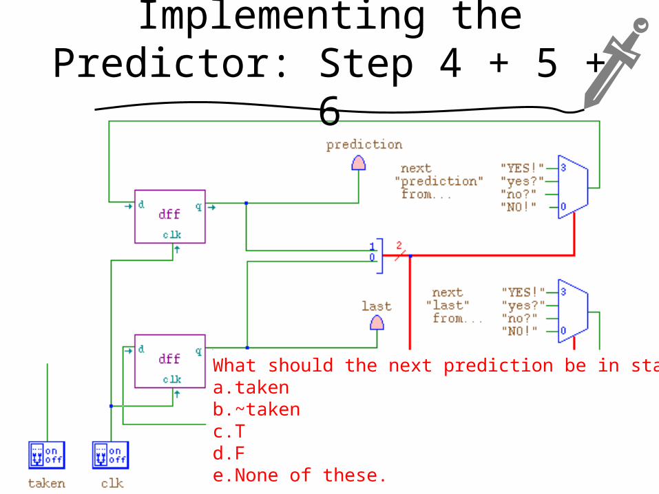
Implementing the Predictor: Step 4 + 5 + 6
What should the next prediction be in state 1?a.takenb.~takenc.Td.Fe.None of these.
52
Implementing the Predictor: Step 4 + 5 + 6
53
What should the next prediction be in state 2?a.takenb.~takenc.Td.Fe.None of these.

Implementing the Predictor: Step 4 + 5 + 6
54
What should the next prediction be in state 3?a.takenb.~takenc.Td.Fe.None of these.
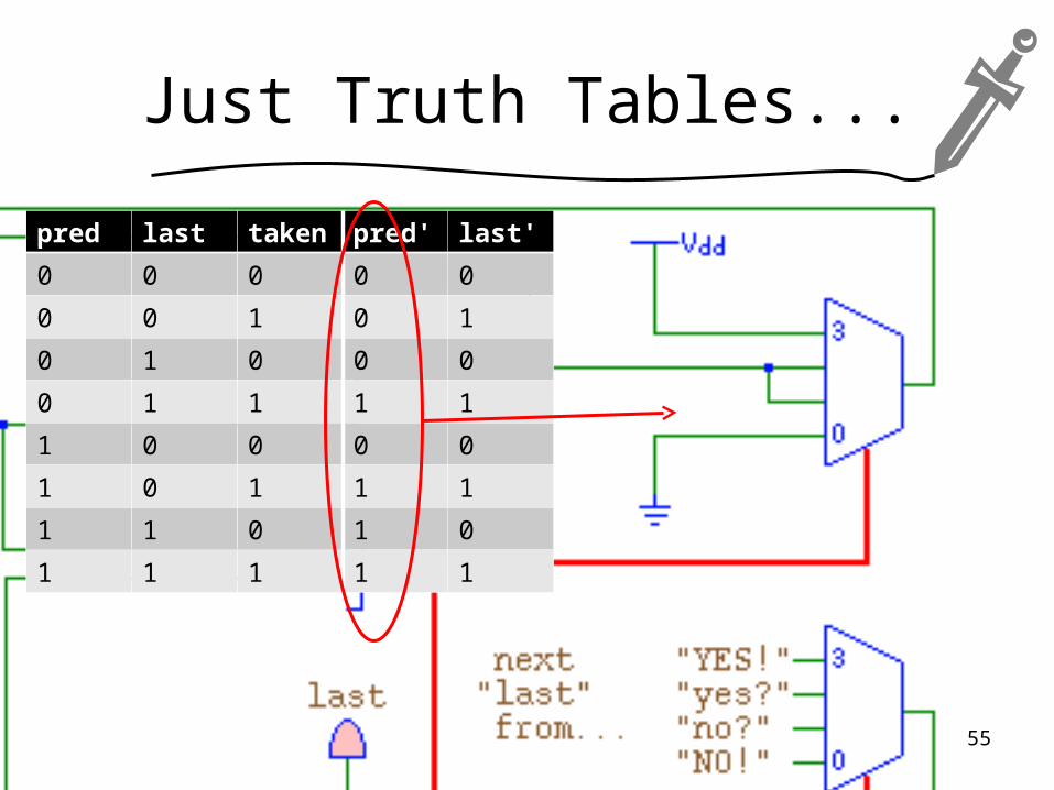
Just Truth Tables...
pred last taken pred' last'
0 0 0 0 0
0 0 1 0 1
0 1 0 0 0
0 1 1 1 1
1 0 0 0 0
1 0 1 1 1
1 1 0 1 0
1 1 1 1 1
55
Implementing the Predictor: Step 4 + 5 + 6
56
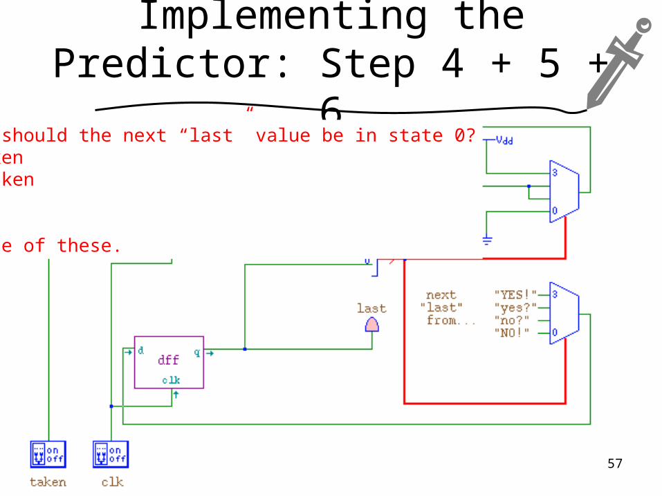
Implementing the Predictor: Step 4 + 5 + 6
What should the next “last” value be in state 0?a.takenb.~takenc.Td.Fe.None of these.
57
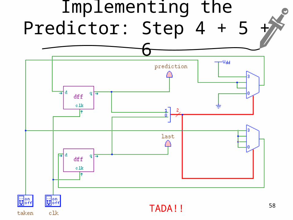
Implementing the Predictor: Step 4 + 5 + 6
TADA!! 58
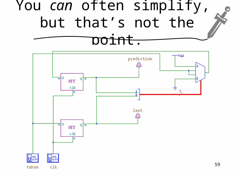
You can often simplify, but that’s not the point.
59
Outline
• Prereqs, Learning Goals, and !Quiz Notes
• Problems and Discussion– A Pushbutton Light Switch– Memory and Events: D Latches & Flip-Flops– General Implementation of DFAs
(with a more complex DFA as an example)– How Powerful are DFAs?
• Next Lecture Notes
60
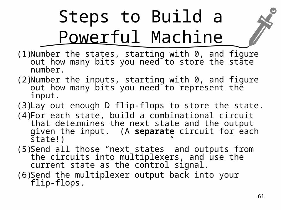
Steps to Build a Powerful Machine
(1) Number the states, starting with 0, and figure out how many bits you need to store the state number.
(2) Number the inputs, starting with 0, and figure out how many bits you need to represent the input.
(3) Lay out enough D flip-flops to store the state.(4) For each state, build a combinational circuit that
determines the next state and the output given the input. (A separate circuit for each state!)
(5) Send all those “next states” and outputs from the circuits into multiplexers, and use the current state as the control signal.
(6) Send the multiplexer output back into your flip-flops.
61
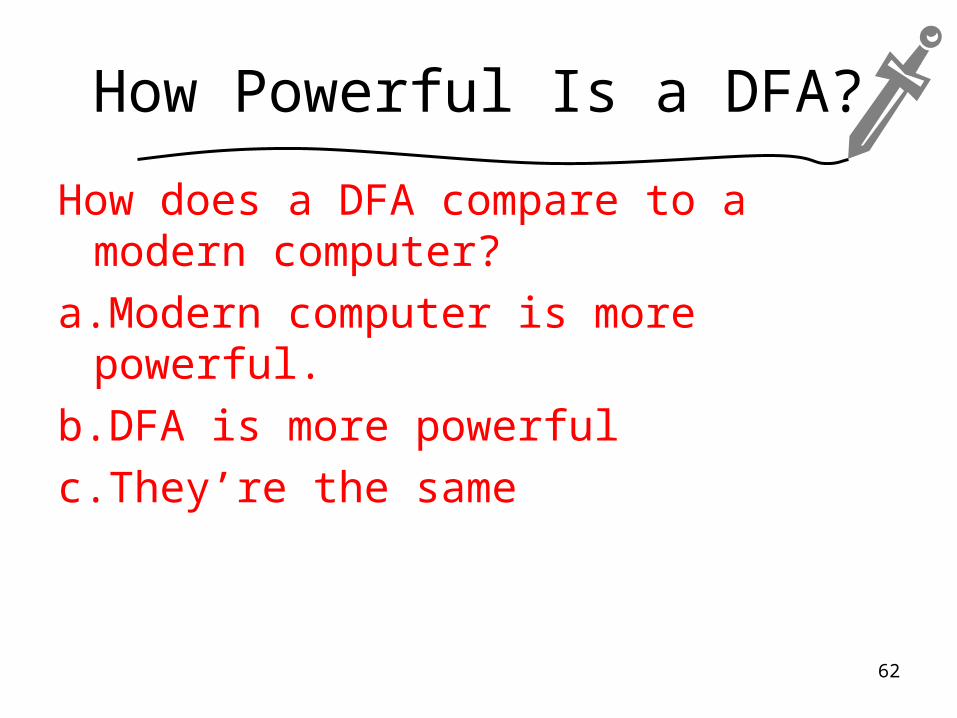
How Powerful Is a DFA?
How does a DFA compare to a modern computer?
a.Modern computer is more powerful.
b.DFA is more powerful
c.They’re the same
62
Where We’ll Go From Here...
We’ll come back to DFAs again later in lecture.
In two upcoming labs, you’ll:
• Build a circuit to perform a practical task using techniques like these.
• Explore how to build something like a DFA that can run other DFAs... a general purpose computer.
63
Outline
• Prereqs, Learning Goals, and !Quiz Notes
• Problems and Discussion– A Pushbutton Light Switch– Memory and Events: D Latches & Flip-Flops– General Implementation of DFAs
(with a more complex DFA as an example)– How Powerful are DFAs?
• Next Lecture Notes
64

Learning Goals: In-Class
By the end of this unit, you should be able to:– Translate a DFA into a sequential circuit that
implements the DFA.– Explain how and why each part of the
resulting circuit works.
65
Next Lecture Learning Goals: Pre-Class
By the start of class, you should be able to:– Convert sequences to and from explicit formulas
that describe the sequence.– Convert sums to and from summation/”sigma”
notation.– Convert products to and from product/”pi”
notation.– Manipulate formulas in summation/product
notation by adjusting their bounds, merging or splitting summations/products, and factoring out values.
66
Next Lecture Prerequisites
Read Section 4.1.
Note: 4.1 is background information. We don’t intend to directly assess this material, but assignment and exam questions may require skills and knowledge from 4.1 to answer.
Solve problems like Exercise Set 4.1, #1-8, 12-14, 18-31, 37-44, 52-60.
Complete the open-book, untimed quiz on Vista that’s due before the next class.
67
snick
snack
More problems to solve...
(on your own or if we have time)
68
Problem: Traffic Light
Problem: Design a DFA with outputs to control a set of traffic lights.
69
Problem: Traffic Light
Problem: Design a DFA with outputs to control a set of traffic lights.
Thought: try allowing an output that sets a timer which in turn causes an input like our toggle when it goes off.
Variants to try:- Pedestrian cross-walks- Turn signals- Inductive sensors to indicate presence of cars- Left-turn signals
70
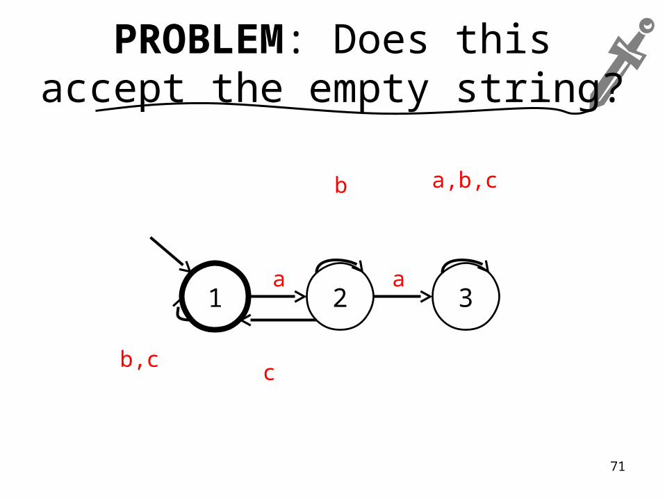
1 2 3a a
a,b,cb
b,cc
PROBLEM: Does this accept the empty string?
71