Embed Size (px)
Citation preview
SNL plummer block housings solve the housing problems
Contents
2
Made by SKF® stands for excellence. It symbolises our consistent endeavour to achieve total quality in everything we do. For those who use our products, “Made by SKF” implies three main benefits.
Reliability – thanks to modern, efficient products, based on our worldwide application know-how, optim-ised materials, forward-looking designs and the most advanced production techniques.
Cost effectiveness – resulting from the favourable ratiobetween our product quality plus service facilities, and the purchase price of the product.
Market lead – which you can achieve by taking advantage of our products and services. Increased operating time and reduced down-time, as well as improved output and product quality are the key to a successful partnership.
1 Product information.................................................. 3
Fewer bearing replacements and less maintenance... 3Plummer block housings have much to offer ................ 3SNL plummer block housings have more to offer ......... 3One basic design – many variants................................ 4Costs and risks – at a low level .................................... 6High performance for all sectors................................... 8
2 Recommendations.................................................... 10
Bearing arrangement design ....................................... 10Bearings on adapter sleeves on smooth shafts............ 10Bearings on adapter sleeves on stepped shafts........... 11Bearings on withdrawal sleeves on stepped shafts ...... 12Bearings on cylindrical seatings on stepped shafts ...... 13Standard seals.............................................................. 14Special seals................................................................. 21End covers.................................................................... 23Locating rings ............................................................... 23Axial displacement using CARB bearings in SNL housings................................................................ 24
Application advice for trouble-free operation............ 26Lubrication .................................................................... 28Mounting ....................................................................... 30Mounting SNL housings with double-lip seals .............. 34Mounting SNL housings with V-ring seals .................... 36Mounting SNL housings with felt seals ......................... 38Mounting SNL housings with labyrinth seals ................ 40Mounting SNL housings with taconite seals ................. 42
3 Product data .............................................................. 44
Designations and housing data .................................. 44Designations ................................................................. 44Load carrying ability ...................................................... 45
Product tables............................................................... 48SNL plummer block housings for bearings on adapter sleeve ......................................................... 48SNL plummer block housings for bearings with cylindrical bore....................................................... 58Sealing arrangements for SNL plummer block housings.. 66
Other products for trouble-free operation.................. 70
The SKF Group – a worldwide corporation................ 74
Fewer bearing replacements and less maintenance
3
1 Product information 2 Recommendations 3 Product data
Customer benefits Page ............. 10 Page ............. 44
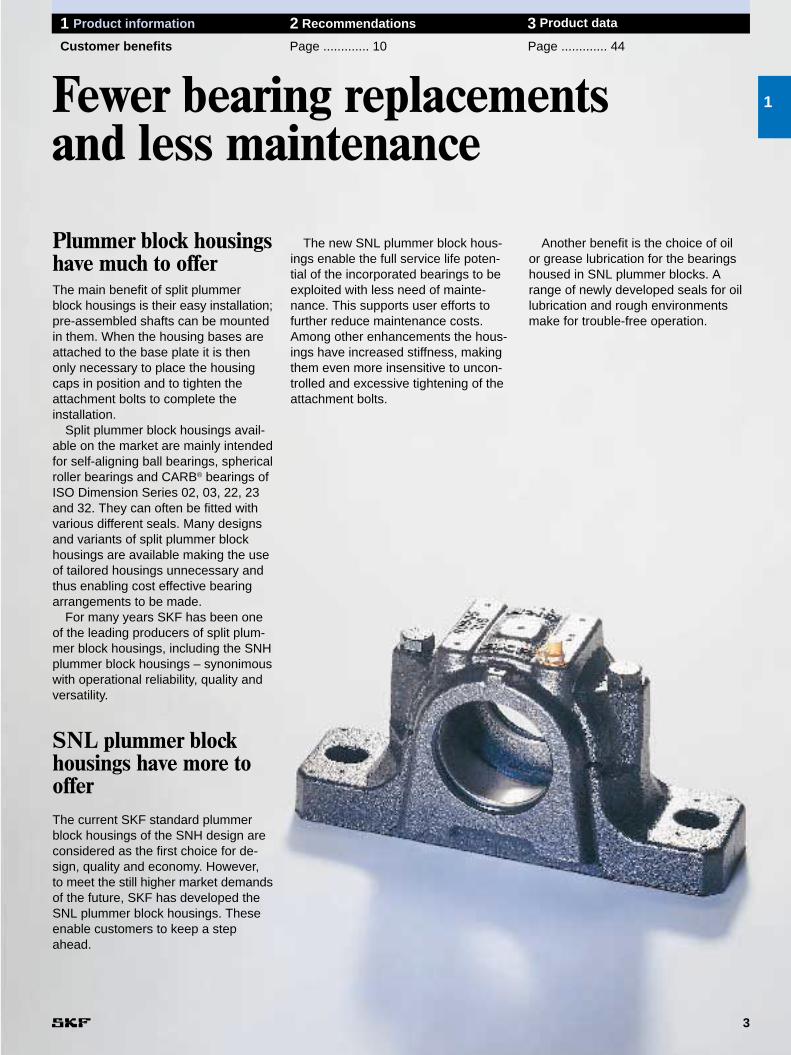
Plummer block housingshave much to offerThe main benefit of split plummerblock housings is their easy installation;pre-assembled shafts can be mountedin them. When the housing bases areattached to the base plate it is thenonly necessary to place the housingcaps in position and to tighten the attachment bolts to complete theinstallation.
Split plummer block housings avail-able on the market are mainly intendedfor self-aligning ball bearings, sphericalroller bearings and CARB® bearings ofISO Dimension Series 02, 03, 22, 23and 32. They can often be fitted withvarious different seals. Many designsand variants of split plummer blockhousings are available making the useof tailored housings unnecessary andthus enabling cost effective bearingarrangements to be made.
For many years SKF has been oneof the leading producers of split plum-mer block housings, including the SNHplummer block housings – synonimouswith operational reliability, quality andversatility.
SNL plummer blockhousings have more toofferThe current SKF standard plummerblock housings of the SNH design areconsidered as the first choice for de-sign, quality and economy. However, to meet the still higher market demandsof the future, SKF has developed theSNL plummer block housings. Theseenable customers to keep a stepahead.
1
The new SNL plummer block hous-ings enable the full service life poten-tial of the incorporated bearings to beexploited with less need of mainte-nance. This supports user efforts tofurther reduce maintenance costs.Among other enhancements the hous-ings have increased stiffness, makingthem even more insensitive to uncon-trolled and excessive tightening of theattachment bolts.
Another benefit is the choice of oil or grease lubrication for the bearingshoused in SNL plummer blocks. Arange of newly developed seals for oillubrication and rough environmentsmake for trouble-free operation.
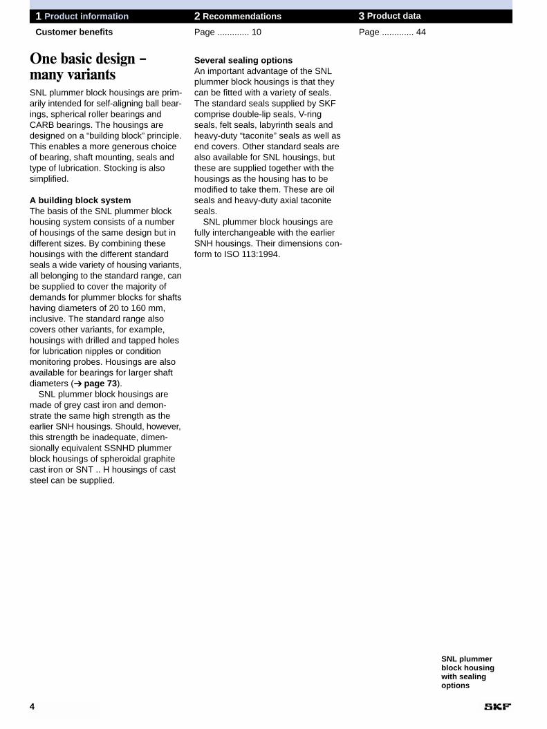
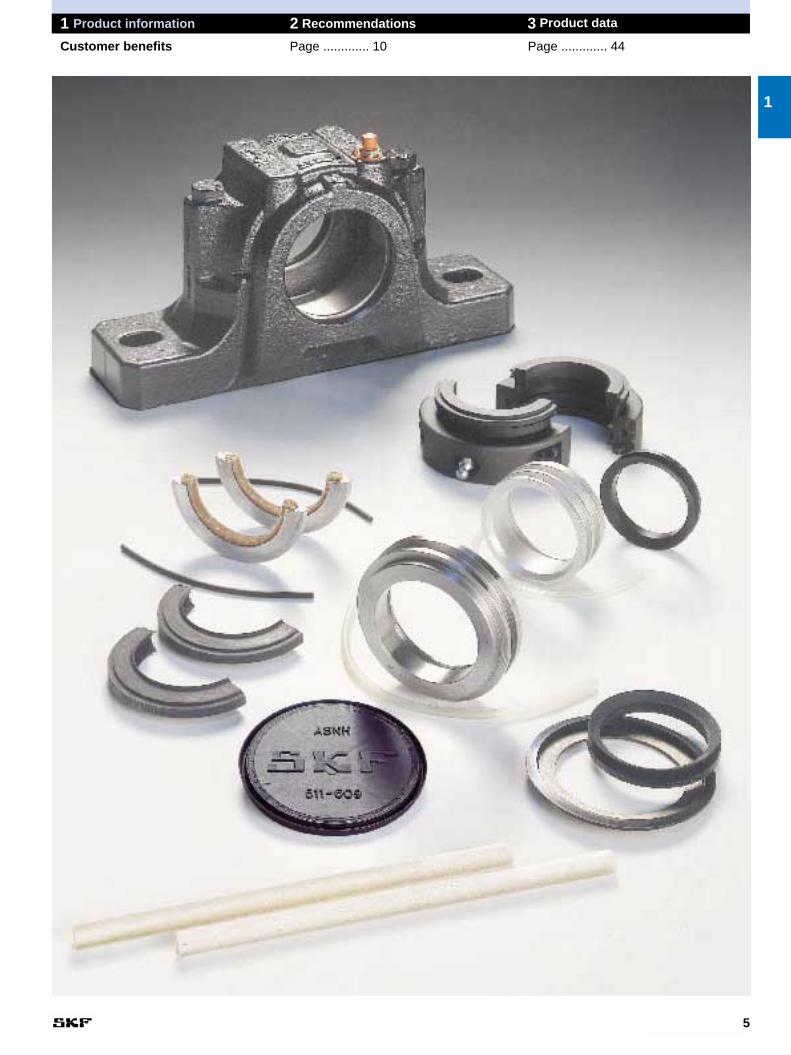
Several sealing optionsAn important advantage of the SNLplummer block housings is that theycan be fitted with a variety of seals.The standard seals supplied by SKFcomprise double-lip seals, V-ringseals, felt seals, labyrinth seals andheavy-duty “taconite” seals as well asend covers. Other standard seals arealso available for SNL housings, butthese are supplied together with thehousings as the housing has to bemodified to take them. These are oilseals and heavy-duty axial taconiteseals.
SNL plummer block housings arefully interchangeable with the earlierSNH housings. Their dimensions con-form to ISO 113:1994.
4
1 Product information 2 Recommendations 3 Product data
Customer benefits Page ............. 10 Page ............. 44
One basic design –many variantsSNL plummer block housings are prim-arily intended for self-aligning ball bear-ings, spherical roller bearings andCARB bearings. The housings aredesigned on a “building block” principle.This enables a more generous choiceof bearing, shaft mounting, seals andtype of lubrication. Stocking is alsosimplified.
A building block systemThe basis of the SNL plummer blockhousing system consists of a numberof housings of the same design but indifferent sizes. By combining thesehousings with the different standardseals a wide variety of housing variants,all belonging to the standard range, canbe supplied to cover the majority ofdemands for plummer blocks for shaftshaving diameters of 20 to 160 mm,inclusive. The standard range alsocovers other variants, for example,housings with drilled and tapped holesfor lubrication nipples or conditionmonitoring probes. Housings are alsoavailable for bearings for larger shaftdiameters (➔ page 73).
SNL plummer block housings aremade of grey cast iron and demon-strate the same high strength as theearlier SNH housings. Should, however,this strength be inadequate, dimen-sionally equivalent SSNHD plummerblock housings of spheroidal graphitecast iron or SNT .. H housings of caststeel can be supplied.
SNL plummerblock housingwith sealingoptions
5
1 Product information 2 Recommendations 3 Product data
Customer benefits Page ............. 10 Page ............. 44
1
6
1 Product information 2 Recommendations 3 Product data
Design characteristics Page ............. 10 Page ............. 44
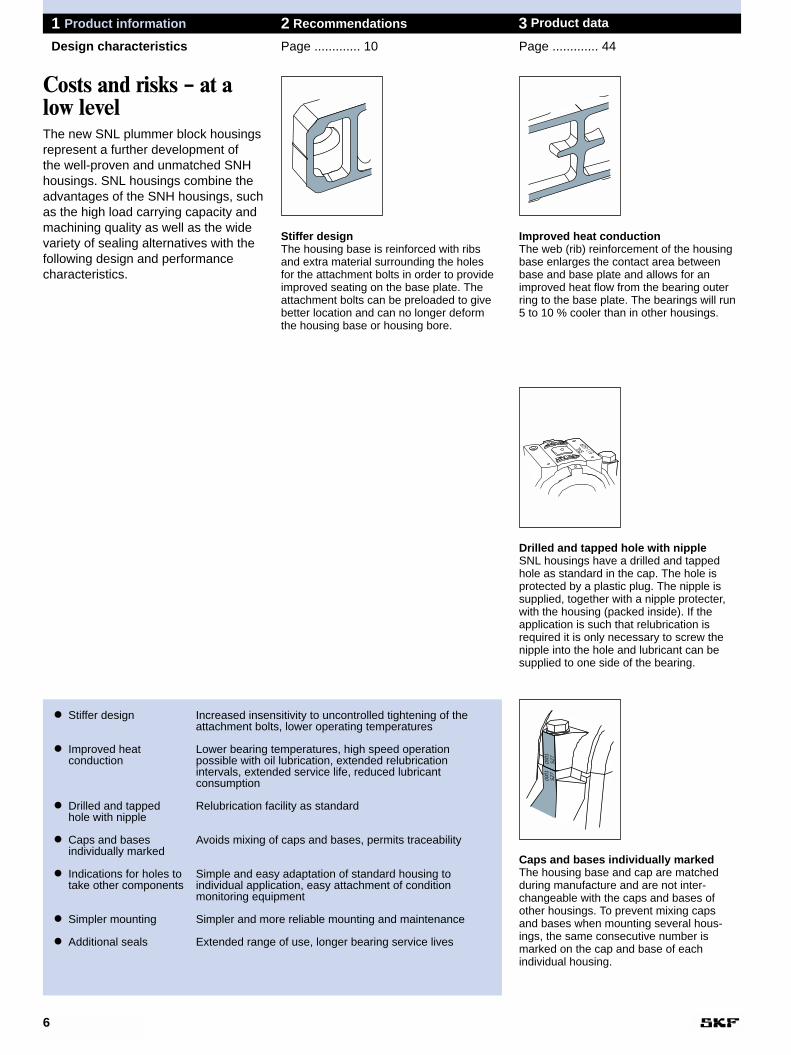
● Stiffer design Increased insensitivity to uncontrolled tightening of the attachment bolts, lower operating temperatures
● Improved heat Lower bearing temperatures, high speed operation conduction possible with oil lubrication, extended relubrication
intervals, extended service life, reduced lubricant consumption
● Drilled and tapped Relubrication facility as standardhole with nipple
● Caps and bases Avoids mixing of caps and bases, permits traceabilityindividually marked
● Indications for holes to Simple and easy adaptation of standard housing to take other components individual application, easy attachment of condition
monitoring equipment
● Simpler mounting Simpler and more reliable mounting and maintenance
● Additional seals Extended range of use, longer bearing service lives
Costs and risks – at alow levelThe new SNL plummer block housingsrepresent a further development of the well-proven and unmatched SNHhousings. SNL housings combine theadvantages of the SNH housings, suchas the high load carrying capacity andmachining quality as well as the widevariety of sealing alternatives with thefollowing design and performance characteristics.
Stiffer designThe housing base is reinforced with ribsand extra material surrounding the holes for the attachment bolts in order to provideimproved seating on the base plate. Theattachment bolts can be preloaded to givebetter location and can no longer deformthe housing base or housing bore.
S27
0001
S27
0001
Improved heat conductionThe web (rib) reinforcement of the housingbase enlarges the contact area betweenbase and base plate and allows for animproved heat flow from the bearing outerring to the base plate. The bearings will run5 to 10 % cooler than in other housings.
Drilled and tapped hole with nippleSNL housings have a drilled and tappedhole as standard in the cap. The hole isprotected by a plastic plug. The nipple issupplied, together with a nipple protecter,with the housing (packed inside). If theapplication is such that relubrication isrequired it is only necessary to screw thenipple into the hole and lubricant can besupplied to one side of the bearing.
Caps and bases individually markedThe housing base and cap are matchedduring manufacture and are not inter-changeable with the caps and bases ofother housings. To prevent mixing caps and bases when mounting several hous-ings, the same consecutive number is marked on the cap and base of each individual housing.
7
1 Product information 2 Recommendations 3 Product data
Design characteristics Page ............. 10 Page ............. 44
1
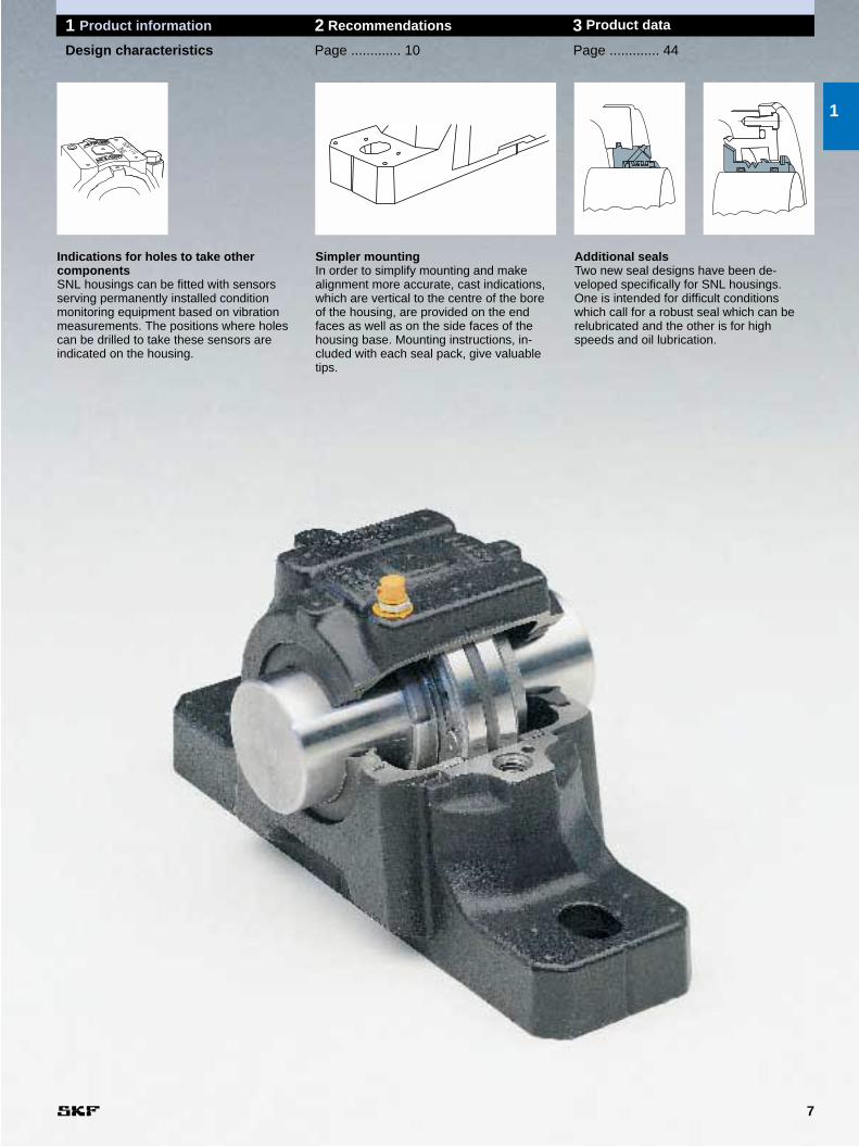
Indications for holes to take other componentsSNL housings can be fitted with sensorsserving permanently installed conditionmonitoring equipment based on vibrationmeasurements. The positions where holescan be drilled to take these sensors areindicated on the housing.
Simpler mountingIn order to simplify mounting and make alignment more accurate, cast indications,which are vertical to the centre of the boreof the housing, are provided on the endfaces as well as on the side faces of thehousing base. Mounting instructions, in-cluded with each seal pack, give valuabletips.
Additional sealsTwo new seal designs have been de-veloped specifically for SNL housings. One is intended for difficult conditions which call for a robust seal which can berelubricated and the other is for highspeeds and oil lubrication.
1 Product information 2 Recommendations 3 Product data
All branches of industry Page ............. 10 Page ............. 44
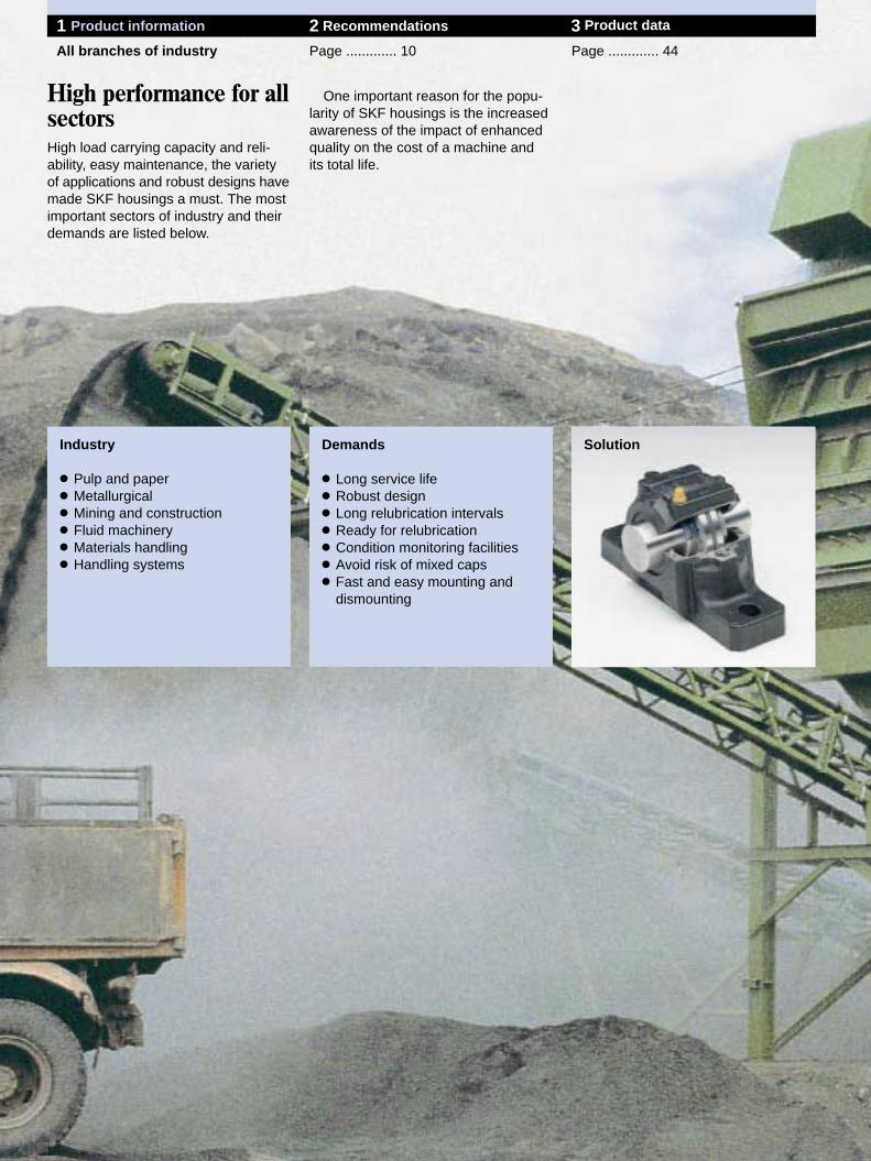
One important reason for the popu-larity of SKF housings is the increasedawareness of the impact of enhancedquality on the cost of a machine and its total life.
Industry
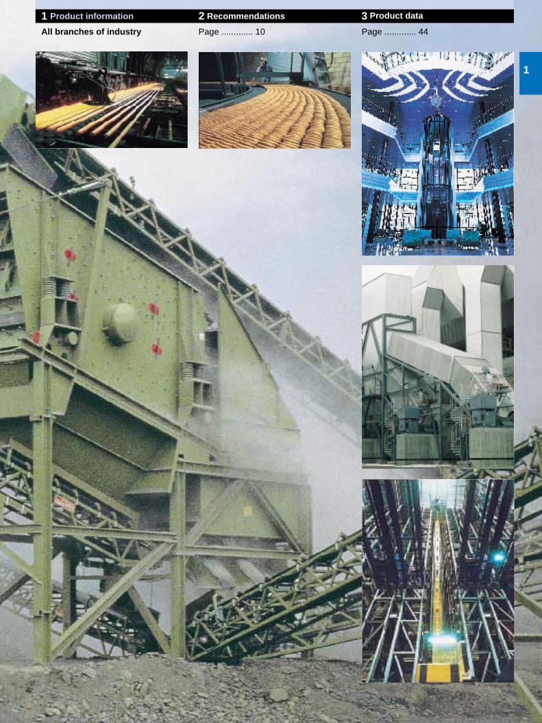
● Pulp and paper● Metallurgical● Mining and construction● Fluid machinery● Materials handling● Handling systems
High performance for allsectorsHigh load carrying capacity and reli-ability, easy maintenance, the varietyof applications and robust designs havemade SKF housings a must. The mostimportant sectors of industry and theirdemands are listed below.
Demands
● Long service life● Robust design● Long relubrication intervals● Ready for relubrication● Condition monitoring facilities● Avoid risk of mixed caps● Fast and easy mounting and
dismounting
Solution
1
1 Product information 2 Recommendations 3 Product data
All branches of industry Page ............. 10 Page ............. 44
Bearing arrangement design
12 EK
SNL 5
22 EK 222 EK 213 CCK23 EK
SNL 6
13 EK 223 EK232 CCK C 22 K C 32 K C 23 K
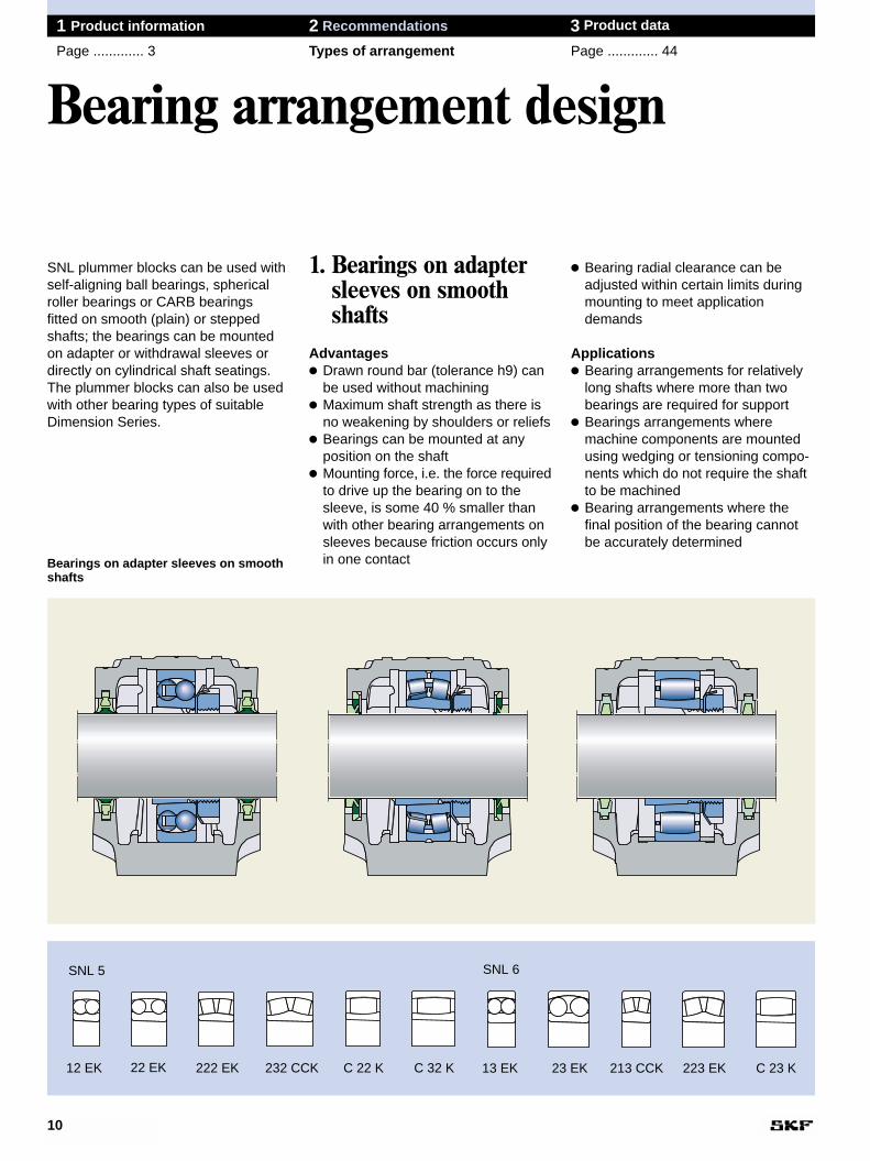
● Bearing radial clearance can beadjusted within certain limits duringmounting to meet applicationdemands
Applications● Bearing arrangements for relatively
long shafts where more than twobearings are required for support
● Bearings arrangements wheremachine components are mountedusing wedging or tensioning compo-nents which do not require the shaftto be machined
● Bearing arrangements where thefinal position of the bearing cannotbe accurately determined
1. Bearings on adaptersleeves on smoothshafts
Advantages● Drawn round bar (tolerance h9) can
be used without machining● Maximum shaft strength as there is
no weakening by shoulders or reliefs● Bearings can be mounted at any
position on the shaft● Mounting force, i.e. the force required
to drive up the bearing on to thesleeve, is some 40 % smaller thanwith other bearing arrangements onsleeves because friction occurs onlyin one contact
10
1 Product information 2 Recommendations 3 Product data
Page ............. 3 Types of arrangement Page ............. 44
SNL plummer blocks can be used withself-aligning ball bearings, sphericalroller bearings or CARB bearings fitted on smooth (plain) or steppedshafts; the bearings can be mountedon adapter or withdrawal sleeves ordirectly on cylindrical shaft seatings.The plummer blocks can also be usedwith other bearing types of suitableDimension Series.
Bearings on adapter sleeves on smoothshafts
12 EK
SNL 5
22 EK 222 EK 213 CCK23 EK
SNL 6
13 EK 223 EK232 CCK C 22 K C 32 K C 23 K
11
1 Product information 2 Recommendations 3 Product data
Page ............. 3 Types of arrangement Page ............. 44
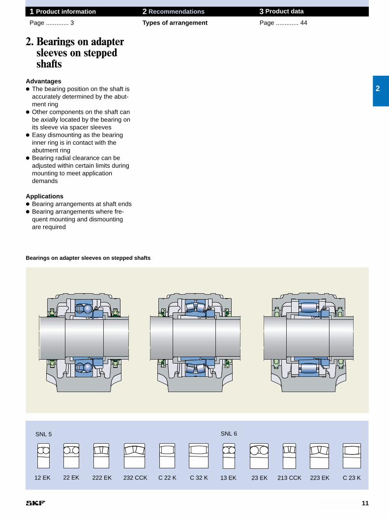
2. Bearings on adaptersleeves on steppedshafts
Advantages● The bearing position on the shaft is
accurately determined by the abut-ment ring
● Other components on the shaft canbe axially located by the bearing onits sleeve via spacer sleeves
● Easy dismounting as the bearinginner ring is in contact with the abutment ring
● Bearing radial clearance can beadjusted within certain limits duringmounting to meet applicationdemands
Applications● Bearing arrangements at shaft ends● Bearing arrangements where fre-
quent mounting and dismounting are required
Bearings on adapter sleeves on stepped shafts
2
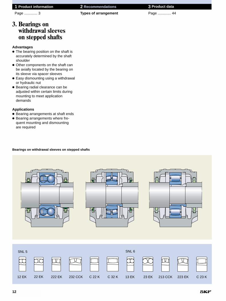
3. Bearings on withdrawal sleeves on stepped shafts
Advantages● The bearing position on the shaft is
accurately determined by the shaftshoulder
● Other components on the shaft canbe axially located by the bearing onits sleeve via spacer sleeves
● Easy dismounting using a withdrawalor hydraulic nut
● Bearing radial clearance can beadjusted within certain limits duringmounting to meet applicationdemands
Applications● Bearing arrangements at shaft ends● Bearing arrangements where fre-
quent mounting and dismounting are required
12
1 Product information 2 Recommendations 3 Product data
Page ............. 3 Types of arrangement Page ............. 44
12 EK
SNL 5
22 EK 222 EK 213 CCK23 EK
SNL 6
13 EK 223 EK232 CCK C 22 K C 32 K C 23 K
Bearings on withdrawal sleeves on stepped shafts
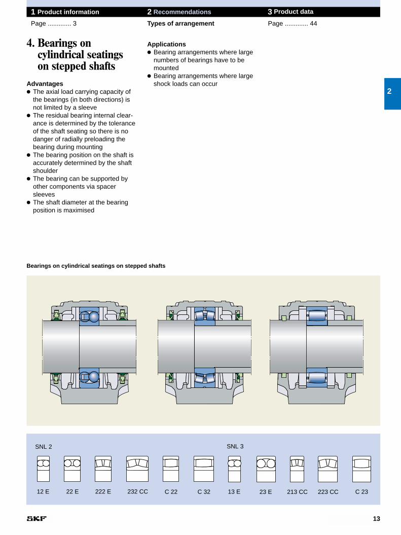
Applications● Bearing arrangements where large
numbers of bearings have to bemounted
● Bearing arrangements where largeshock loads can occur
13
1 Product information 2 Recommendations 3 Product data
Page ............. 3 Types of arrangement Page ............. 44
4. Bearings on cylindrical seatings on stepped shafts
Advantages● The axial load carrying capacity of
the bearings (in both directions) isnot limited by a sleeve
● The residual bearing internal clear-ance is determined by the toleranceof the shaft seating so there is nodanger of radially preloading thebearing during mounting
● The bearing position on the shaft isaccurately determined by the shaftshoulder
● The bearing can be supported byother components via spacer sleeves
● The shaft diameter at the bearingposition is maximised
2
12 E
SNL 2
22 E 222 E 232 CC C 22 C 32
SNL 3
213 CC23 E13 E 223 CC C 23
Bearings on cylindrical seatings on stepped shafts
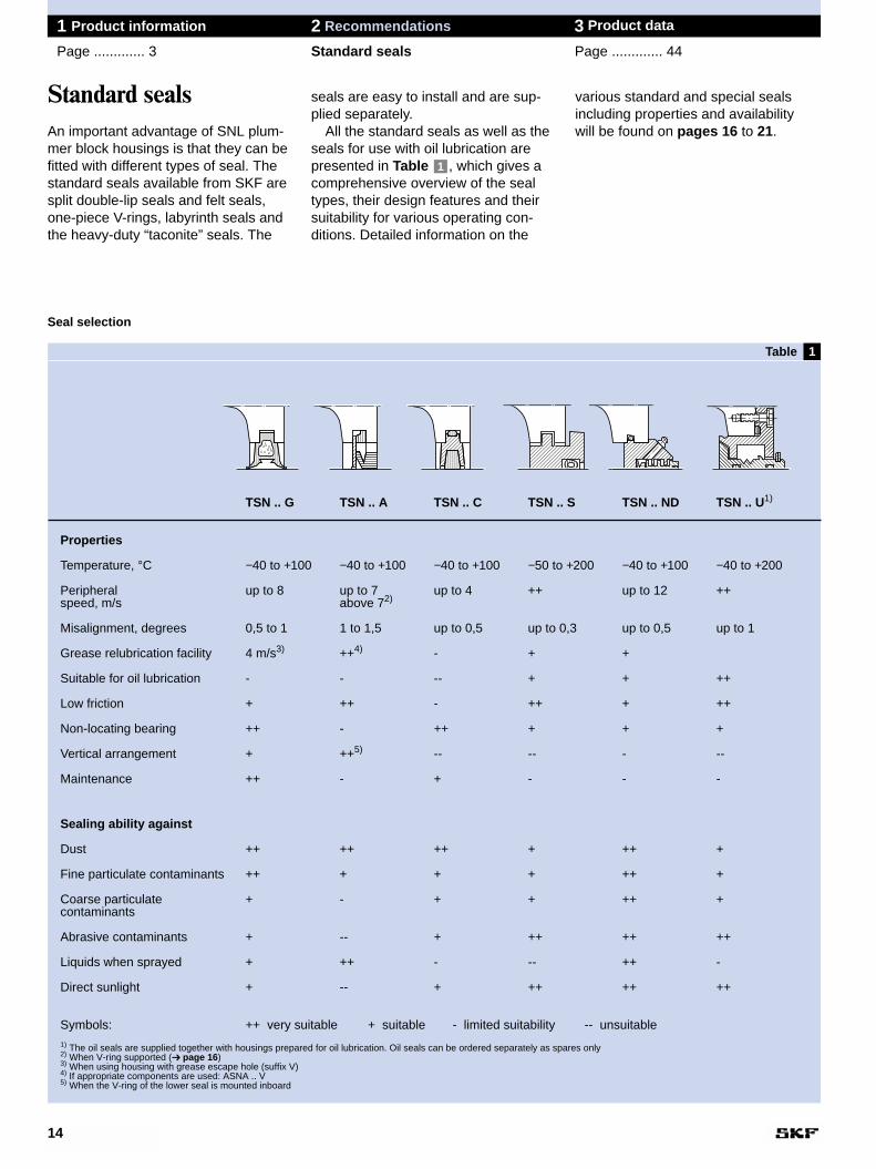
TSN .. G TSN .. A TSN .. C TSN .. S TSN .. ND TSN .. U1)
Properties
Temperature, °C −40 to +100 −40 to +100 −40 to +100 −50 to +200 −40 to +100 −40 to +200
Peripheral up to 8 up to 7 up to 4 ++ up to 12 ++speed, m/s above 72)
Misalignment, degrees 0,5 to 1 1 to 1,5 up to 0,5 up to 0,3 up to 0,5 up to 1
Grease relubrication facility 4 m/s3) ++4) - + +
Suitable for oil lubrication - - -- + + ++
Low friction + ++ - ++ + ++
Non-locating bearing ++ - ++ + + +
Vertical arrangement + ++5) -- -- - --
Maintenance ++ - + - - -
Sealing ability against
Dust ++ ++ ++ + ++ +
Fine particulate contaminants ++ + + + ++ +
Coarse particulate + - + + ++ +contaminants
Abrasive contaminants + -- + ++ ++ ++
Liquids when sprayed + ++ - -- ++ -
Direct sunlight + -- + ++ ++ ++
Symbols: ++ very suitable + suitable - limited suitability -- unsuitable1) The oil seals are supplied together with housings prepared for oil lubrication. Oil seals can be ordered separately as spares only2) When V-ring supported (➔ page 16)3) When using housing with grease escape hole (suffix V)4) If appropriate components are used: ASNA .. V5) When the V-ring of the lower seal is mounted inboard
1
various standard and special sealsincluding properties and availability will be found on pages 16 to 21.
seals are easy to install and are sup-plied separately.
All the standard seals as well as theseals for use with oil lubrication arepresented in Table , which gives acomprehensive overview of the sealtypes, their design features and theirsuitability for various operating con-ditions. Detailed information on the
1
14
1 Product information 2 Recommendations 3 Product data
Page ............. 3 Standard seals Page ............. 44
Standard sealsAn important advantage of SNL plum-mer block housings is that they can befitted with different types of seal. Thestandard seals available from SKF aresplit double-lip seals and felt seals,one-piece V-rings, labyrinth seals andthe heavy-duty “taconite” seals. The
Seal selection
����� �
�
������ ����� �
�����������
�� ���� ���
��
Table
C design A design G designfelt seals V-ring seals double-lip seals
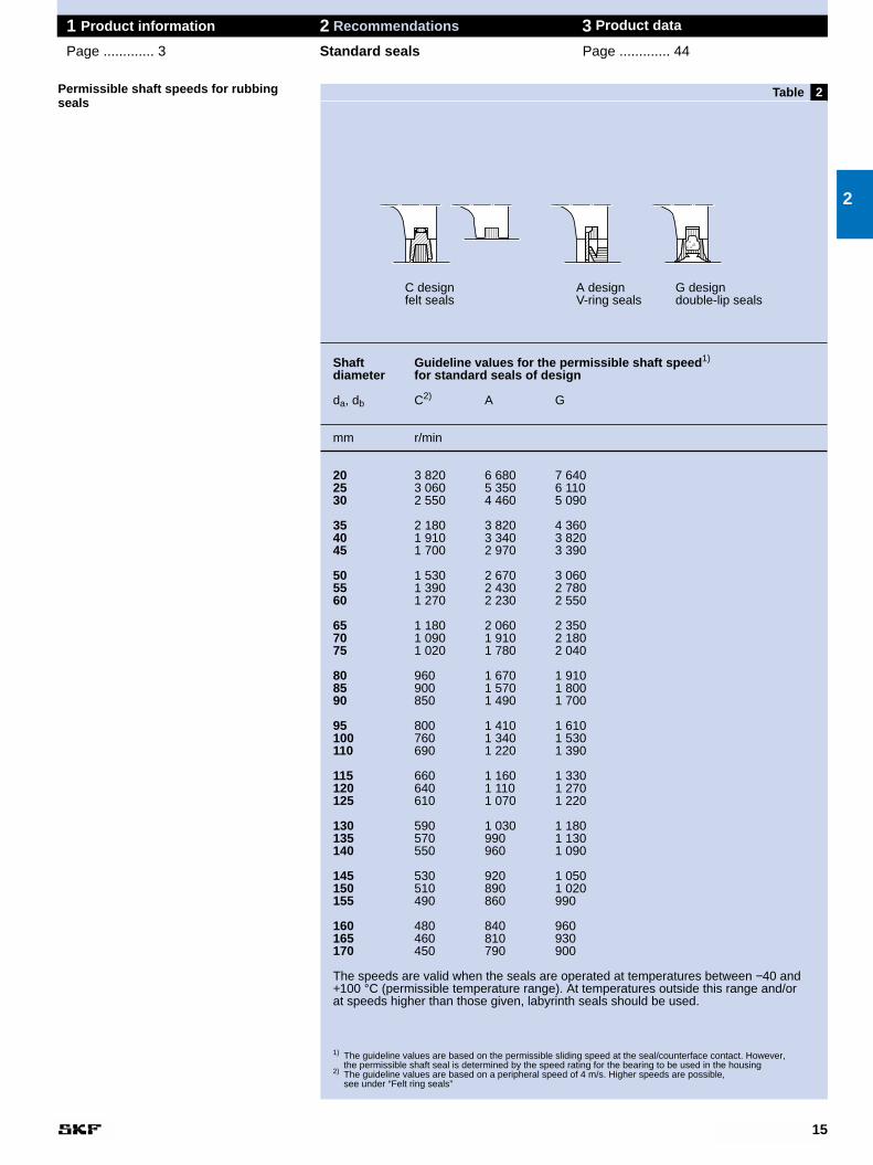
Shaft Guideline values for the permissible shaft speed1)
diameter for standard seals of design
da, db C2) A G
mm r/min
20 3 820 6 680 7 64025 3 060 5 350 6 11030 2 550 4 460 5 090
35 2 180 3 820 4 36040 1 910 3 340 3 82045 1 700 2 970 3 390
50 1 530 2 670 3 06055 1 390 2 430 2 78060 1 270 2 230 2 550
65 1 180 2 060 2 35070 1 090 1 910 2 18075 1 020 1 780 2 040
80 960 1 670 1 91085 900 1 570 1 80090 850 1 490 1 700
95 800 1 410 1 610100 760 1 340 1 530110 690 1 220 1 390
115 660 1 160 1 330120 640 1 110 1 270125 610 1 070 1 220
130 590 1 030 1 180135 570 990 1 130140 550 960 1 090
145 530 920 1 050150 510 890 1 020155 490 860 990
160 480 840 960165 460 810 930170 450 790 900
The speeds are valid when the seals are operated at temperatures between −40 and+100 °C (permissible temperature range). At temperatures outside this range and/or at speeds higher than those given, labyrinth seals should be used.
1) The guideline values are based on the permissible sliding speed at the seal/counterface contact. However, the permissible shaft seal is determined by the speed rating for the bearing to be used in the housing
2) The guideline values are based on a peripheral speed of 4 m/s. Higher speeds are possible, see under “Felt ring seals”
15
1 Product information 2 Recommendations 3 Product data
Page ............. 3 Standard seals Page ............. 44
2
2Permissible shaft speeds for rubbingseals
����
����
������
Table
1
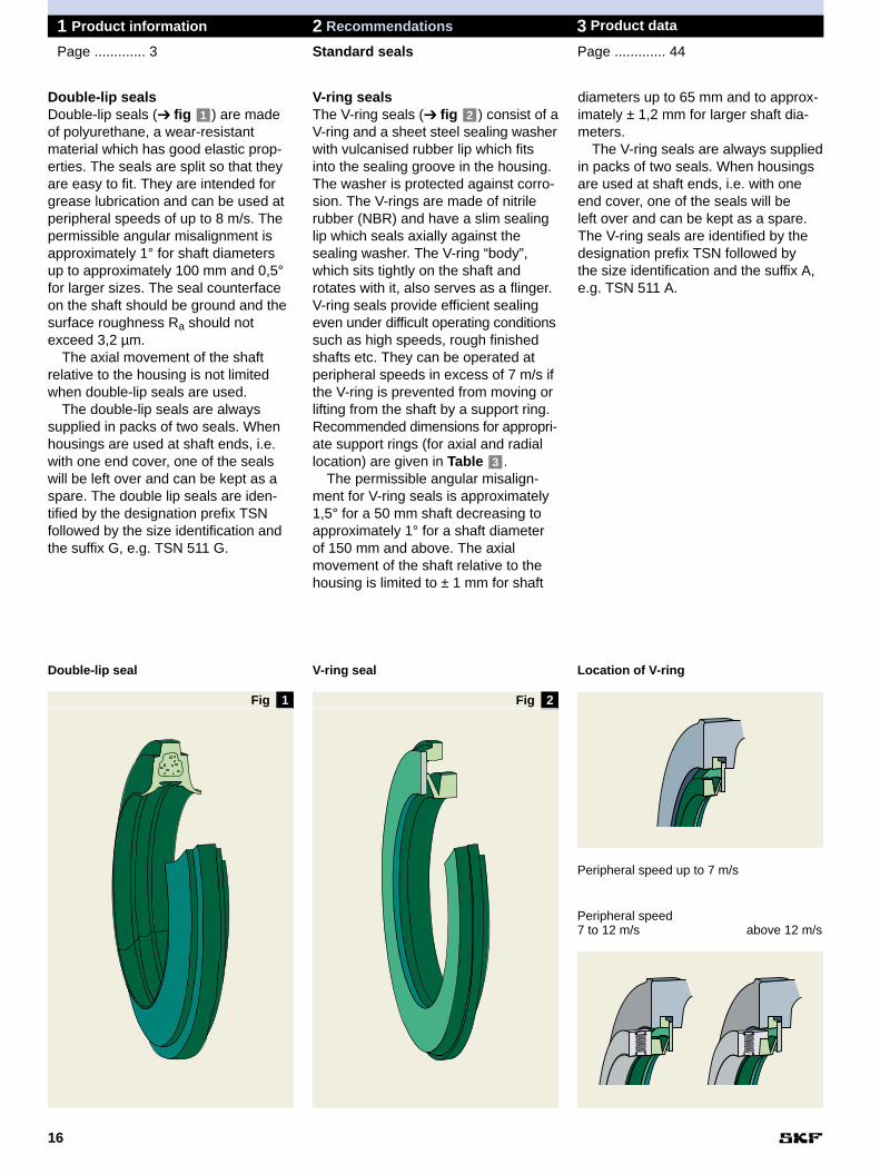
diameters up to 65 mm and to approx-imately ± 1,2 mm for larger shaft dia-meters.
The V-ring seals are always suppliedin packs of two seals. When housingsare used at shaft ends, i.e. with oneend cover, one of the seals will be left over and can be kept as a spare. The V-ring seals are identified by thedesignation prefix TSN followed by the size identification and the suffix A,e.g. TSN 511 A.
V-ring sealsThe V-ring seals (➔ fig ) consist of aV-ring and a sheet steel sealing washerwith vulcanised rubber lip which fitsinto the sealing groove in the housing.The washer is protected against corro-sion. The V-rings are made of nitrilerubber (NBR) and have a slim sealinglip which seals axially against the sealing washer. The V-ring “body”,which sits tightly on the shaft and rotates with it, also serves as a flinger.V-ring seals provide efficient sealingeven under difficult operating conditionssuch as high speeds, rough finishedshafts etc. They can be operated atperipheral speeds in excess of 7 m/s ifthe V-ring is prevented from moving orlifting from the shaft by a support ring.Recommended dimensions for appropri-ate support rings (for axial and radiallocation) are given in Table .
The permissible angular misalign-ment for V-ring seals is approximately1,5° for a 50 mm shaft decreasing toapproximately 1° for a shaft diameterof 150 mm and above. The axialmovement of the shaft relative to thehousing is limited to ± 1 mm for shaft
3
2
16
1 Product information 2 Recommendations 3 Product data
Page ............. 3 Standard seals Page ............. 44
Double-lip seals Double-lip seals (➔ fig ) are madeof polyurethane, a wear-resistantmaterial which has good elastic prop-erties. The seals are split so that theyare easy to fit. They are intended forgrease lubrication and can be used atperipheral speeds of up to 8 m/s. Thepermissible angular misalignment isapproximately 1° for shaft diametersup to approximately 100 mm and 0,5°for larger sizes. The seal counterfaceon the shaft should be ground and thesurface roughness Ra should notexceed 3,2 µm.
The axial movement of the shaft relative to the housing is not limitedwhen double-lip seals are used.
The double-lip seals are always supplied in packs of two seals. Whenhousings are used at shaft ends, i.e.with one end cover, one of the sealswill be left over and can be kept as aspare. The double lip seals are iden-tified by the designation prefix TSN followed by the size identification andthe suffix G, e.g. TSN 511 G.
1
Double-lip seal
2
V-ring seal Location of V-ring
Peripheral speed 7 to 12 m/s above 12 m/s
Peripheral speed up to 7 m/s
Fig Fig
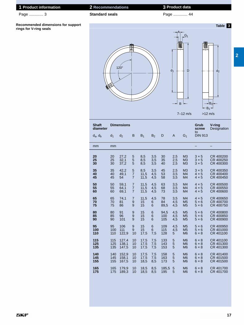
Shaft Dimensions Grub V-ringdiameter screw Designation
toda, db d1 d2 B B1 B2 D A G1 DIN 913
mm mm – –
20 20 27,2 5 8,5 3,5 30 2,5 M3 3 × 5 CR 40020025 25 32,1 5 8,5 3,5 35 2,5 M3 3 × 5 CR 40025030 30 37,2 5 8,5 3,5 40 2,5 M3 3 × 5 CR 400300
35 35 42,2 5 8,5 3,5 45 2,5 M3 3 × 5 CR 40035040 40 49,1 7 11,5 4,5 53 3,5 M4 4 × 5 CR 40040045 45 54 7 11,5 4,5 58 3,5 M4 4 × 5 CR 400450
50 50 59,1 7 11,5 4,5 63 3,5 M4 4 × 5 CR 40050055 55 64,1 7 11,5 4,5 68 3,5 M4 4 × 5 CR 40055060 60 69,1 7 11,5 4,5 73 3,5 M4 4 × 5 CR 400600
65 65 74,1 7 11,5 4,5 78 3,5 M4 4 × 5 CR 40065070 70 81 9 15 6 84 4,5 M5 5 × 6 CR 40070075 75 86 9 15 6 89,5 4,5 M5 5 × 6 CR 400750
80 80 91 9 15 6 94,5 4,5 M5 5 × 6 CR 40080085 85 96 9 15 6 100 4,5 M5 5 × 6 CR 40085090 90 101 9 15 6 105 4,5 M5 5 × 6 CR 400900
95 95 106 9 15 6 109 4,5 M5 5 × 6 CR 400950100 100 111 9 15 6 115 4,5 M5 5 × 6 CR 401000110 110 122,9 10 17,5 7,5 128 5 M6 6 × 8 CR 401100
115 115 127,4 10 17,5 7,5 133 5 M6 6 × 8 CR 401100125 125 138,1 10 17,5 7,5 143 5 M6 6 × 8 CR 401300135 135 147,5 10 17,5 7,5 153 5 M6 6 × 8 CR 401300
140 140 152,9 10 17,5 7,5 158 5 M6 6 × 8 CR 401400145 145 158,1 10 17,5 7,5 163 5 M6 6 × 8 CR 401500155 155 167,5 10 18,5 8,5 173 5 M6 6 × 8 CR 401500
165 165 179,9 10 18,5 8,5 185,5 5 M6 6 × 8 CR 401700175 175 189,3 10 18,5 8,5 195 5 M6 6 × 8 CR 401700
3
17
1 Product information 2 Recommendations 3 Product data
Page ............. 3 Standard seals Page ............. 44
Recommended dimensions for supportrings for V-ring seals
2
120°
B2
d2
B1
Table
GA
d1 D
B
1
7–12 m/s >12 m/s
3
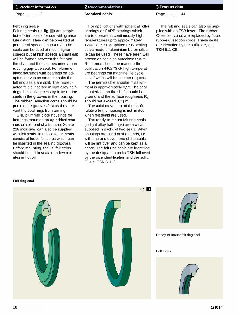
The felt ring seals can also be sup-plied with an FSB insert. The rubberO-section cords are replaced by fluororubber O-section cords. These sealsare identified by the suffix CB, e.g.TSN 511 CB.
For applications with spherical rollerbearings or CARB bearings which are to operate at continuously hightemperatures up to approximately+200 °C, SKF graphited FSB sealingstrips made of aluminium boron silica-te can be used. These have been wellproven as seals on autoclave trucks.Reference should be made to the publication 4402 “SKF high temperat-ure bearings cut machine life cyclecosts” which will be sent on request.
The permissible angular misalign-ment is approximately 0,5°. The sealcounterface on the shaft should beground and the surface roughness Rashould not exceed 3,2 µm.
The axial movement of the shaft relative to the housing is not limitedwhen felt seals are used.
The ready-to-mount felt ring seals (in light alloy half-rings) are alwayssupplied in packs of two seals. Whenhousings are used at shaft ends, i.e.with one end cover, one of the sealswill be left over and can be kept as aspare. The felt ring seals are identifiedby the designation prefix TSN followedby the size identification and the suffixC, e.g. TSN 511 C.
Felt ring seals Felt ring seals (➔ fig ) are simplebut efficient seals for use with greaselubrication. They can be operated atperipheral speeds up to 4 m/s. Theseals can be used at much higherspeeds but at high speeds a small gapwill be formed between the felt and the shaft and the seal becomes a non-rubbing gap-type seal. For plummerblock housings with bearings on ad-apter sleeves on smooth shafts the felt ring seals are split. The impreg-nated felt is inserted in light alloy half-rings. It is only necessary to insert theseals in the grooves in the housing.The rubber O-section cords should beput into the grooves first as they pre-vent the seal rings from turning.
SNL plummer block housings forbearings mounted on cylindrical seat-ings on stepped shafts, sizes 205 to218 inclusive, can also be suppliedwith felt seals. In this case the sealsconsist of loose felt strips which can be inserted in the sealing grooves.Before mounting, the FS felt stripsshould be left to soak for a few min-utes in hot oil.
3
18
1 Product information 2 Recommendations 3 Product data
Page ............. 3 Standard seals Page ............. 44
Felt ring seal
Ready-to-mount felt ring seal
Felt strips
Fig

Taconite heavy-duty sealsTaconite is a very fine-grained mineralwhich is extremely difficult to sealagainst. For bearing arrangementswhich must operate under very arduousconditions such as those encounteredin mining, labyrinth seals which can be relubricated are recommended, asgrease enhances the sealing effectand extends the serviceability of theseals. SKF has developed two differentdesigns of these heavy-duty seals(which can seal against taconite, hencethe name) which can be supplied foruse with SNL housings.
The one taconite seal design (➔ fig ) is based on a radial laby-rinth seal and fits the standard hous-ings. A V-ring seal mounted on theshaft seals against the non-rotatingpart of the seal, which is inserted in the seal groove and prevents contam-inants from penetrating to the bearingwhen the seal is relubricated. This grease is supplied via a grease nipplein the non-rotating part of the seal.Angular misalignments of the shaft ofup to approximately 0,5° are possible.The permissible operating temperature
5
range for the seal is between −40 and+100 °C.
The axial movement of the shaft relative to the housing is limited for this type of taconite seal to ±1 mm forshaft diameters up to 65 mm and toapproximately ±1,2 mm for sizes up to100 mm and ±1,5 mm for larger shaftdiameters.
These seals are supplied singly so that for housings used on throughshafts, it is necessary to order twoseals. The seal is identified by the pre-fix TSN followed by the size identifica-tion and the suffix ND, e.g. TSN 511ND.
The other design of taconite seal (➔ fig ) is based on a labyrinth sealwith the labyrinth stages arranged axially and does not fit the standardhousings. The seal is relubricated vialubrication holes and nipples in thehousing cap. The positions for theholes are marked by dimples in thecasting. The permissible misalignmentof the shaft relative to the housing forthis seal is approximately 0,5°. Theoperating temperature range is from −40 to +250 °C. Axial movement of the
6
19
1 Product information 2 Recommendations 3 Product data
Page ............. 3 Standard seals Page ............. 44
Labyrinth sealsUnder difficult operating conditionsand/or at high speeds the use of laby-rinth seals (➔ fig ) is recommend-ed. The labyrinth rings are made ofsteel and have two radially arrangedlabyrinth steps which form a narrowsealing gap with the housing grooves.
Hollow O-ring cords of silicone rubber (supplied with the seals) en-sure that the labyrinth rings, which are mounted with a loose fit, rotatewith the shaft. Angular misalignmentsof the shaft up to approximately 0,3°are permissible. The operating tem-perature range for the labyrinth sealsis −50 to +200 °C.
When labyrinth seals are used, axialmovement of the shaft relative to thehousing is not limited.
The labyrinth seals are suppliedsingly. For bearing arrangements forthrough shafts it is therefore neces-sary to order two rings. The labyrinthseal is identified by the prefix TSN followed by the size identification andthe suffix S, e.g. TSN 511 S.
4
2
5 6
Labyrinth seal Taconite heavy-duty seal Taconite heavy-duty seal
4Fig Fig Fig
7
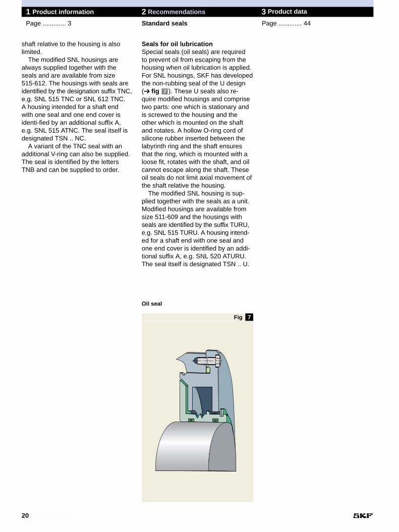
Seals for oil lubricationSpecial seals (oil seals) are required to prevent oil from escaping from thehousing when oil lubrication is applied.For SNL housings, SKF has developedthe non-rubbing seal of the U design(➔ fig ). These U seals also re-quire modified housings and comprisetwo parts: one which is stationary andis screwed to the housing and theother which is mounted on the shaftand rotates. A hollow O-ring cord of silicone rubber inserted between thelabyrinth ring and the shaft ensuresthat the ring, which is mounted with aloose fit, rotates with the shaft, and oilcannot escape along the shaft. Theseoil seals do not limit axial movement ofthe shaft relative the housing.
The modified SNL housing is sup-plied together with the seals as a unit.Modified housings are available fromsize 511-609 and the housings withseals are identified by the suffix TURU,e.g. SNL 515 TURU. A housing intend-ed for a shaft end with one seal andone end cover is identified by an addi-tional suffix A, e.g. SNL 520 ATURU.The seal itself is designated TSN .. U.
7
shaft relative to the housing is also limited.
The modified SNL housings arealways supplied together with theseals and are available from size 515-612. The housings with seals areidentified by the designation suffix TNC,e.g. SNL 515 TNC or SNL 612 TNC. A housing intended for a shaft end with one seal and one end cover isidenti-fied by an additional suffix A,e.g. SNL 515 ATNC. The seal itself isdesignated TSN .. NC.
A variant of the TNC seal with anadditional V-ring can also be supplied.The seal is identified by the lettersTNB and can be supplied to order.
20
1 Product information 2 Recommendations 3 Product data
Page ............. 3 Standard seals Page ............. 44
Oil seal
Fig
Housing DimensionsSize A3 A4 A5 A6 Db Dc
– mm
SNL 205 44 5 7,5 10 36,5 44,5SNL 206-305 54 5 7,5 10 46,5 54,5SNL 207 58 5 8 11 56,5 64,5
SNL 208-307 61 5 8 11 62 70,5SNL 209 59 5 9 12 67 75,5SNL 210 64 5 9 12 72 80,5
SNL 211 69 5 9 12 77 85,5SNL 212 79 5 9 12 87 95,5SNL 213 82 5 9 13 92,5 101
SNL 215 87 5 9 13 102,5 111SNL 216 92 5 9 13 108 116,5SNL 217 97 5 9 13 112 120,5SNL 218 112 5 9 13 120 128,5
SNL 505 45 5 7,5 10 31,5 39,5SNL 506-605 55 5 7,5 10 36,5 44,5SNL 507-606 59 5 8 11 46,5 54,5
SNL 508-607 62 5 8 11 51,5 59,5SNL 509 60 5 9 12 56,5 64,5SNL 510-608 65 5 9 12 62 70,5
SNL 511-609 70 5 9 12 67 75,5SNL 512-610 80 5 9 12 72 80,5SNL 513-611 83 5 9 13 77 85,5
SNL 515-612 88 5 9 13 87 95,5SNL 516-613 93 5 9 13 92,5 101SNL 517 98 5 9 13 97,5 106
SNL 518-615 113 5 9 13 102,5 111SNL 519-616 116 6 10 14 131 141SNL 520-617 131 6 10 14 137,5 147,5
SNL 522-619 143 6 10 14 147,5 157,5SNL 524-620 151 6 11 15 157,5 167,5SNL 526 156 6 11 15 167,5 177,5
SNL 528 171 6 11 15 177,5 187,5SNL 530 189 6 11 15 192,5 202,5SNL 532 201 6 11 15 202,5 212,5
4
21
1 Product information 2 Recommendations 3 Product data
Page ............. 3 Special seals Page ............. 44
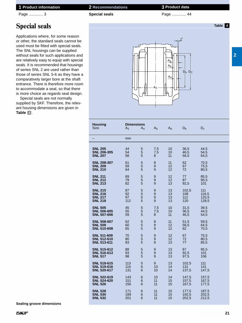
Special sealsApplications where, for some reason or other, the standard seals cannot beused must be fitted with special seals.The SNL housings can be supplied without seals for such applications andare relatively easy to equip with specialseals. It is recommended that housingsof series SNL 2 are used rather thanthose of series SNL 5-6 as they have acomparatively larger bore at the shaftentrance. There is therefore more roomto accommodate a seal, so that thereis more choice as regards seal design.
Special seals are not normally supplied by SKF. Therefore, the relev-ant housing dimensions are given inTable .4
2
Sealing groove dimensions
A4
A5
A6
A3
DCDb
1°
Table
Housing Dimensions Widest bearing to fit housingSize Designation Dimensions
ba1) bc Ca B bb
– mm – mm
SNL 205 18 24 25 22205 CC/W33 18 17SNL 206-305 20 29 32 22206 CC/W33 20 18SNL 207 23 32 34 22207 CC/W33 23 20,5
SNL 208-307 26 (22) 33 39 22208 E 23 21,5SNL 209 25 32 30 22209 CC/W33 23 22,5SNL 210 28 (24) 35 41 22210 CC/W33 23 23,5
SNL 211 30 (25) 37 44 22211 E 25 25SNL 212 33 (26) 42 48 22212 E 28 27SNL 213 35 (30) 45 51 22213 CC/W33 31 29,5
SNL 215 37 (30) 47 56 22215 E 31 30,5SNL 216 39 (33) 50 58 22216 E 33 33,5SNL 217 40 (35) 52 61 22217 E 36 36SNL 218 45 (35) 60 65 23218 CC/W33 52,4 44,2
SNL 505 18 24 25 22205 CCK/W33 18 17SNL 506-605 20 29 32 2305 EK 24 19SNL 507-606 23 32 34 2306 K 27 21,5
SNL 508-607 26 (22) 33 39 2307 EK 31 24,5SNL 509 25 32 30 22209 CCK/W33 23 22,5SNL 510-608 28 (24) 35 41 22308 CCK/W33 33 26,5
SNL 511-609 30 (25) 37 44 22309 CCK/W33 36 29SNL 512-610 33 (26) 42 48 22310 EK 40 32SNL 513-611 35 (30) 45 51 22311 EK 43 33,5
SNL 515-612 37 (30) 47 56 22312 EK 46 36SNL 516-613 39 (33) 50 58 22313 EK 48 38SNL 517 40 (35) 52 61 22217 EK 36 36
SNL 518-615 45 (35) 60 65 22315 EK 55 42,5SNL 519-616 47 (40) 61 68 22316 EK 58 46SNL 520-617 51 (45) 69 70 23220 CCK/W33 60,3 50,2
SNL 522-619 61 75 80 23222 CCK/W33 69,8 55,9SNL 524-620 65 79 86 23224 CCK/W33 76 60SNL 526 65 81 90 23226 CCK/W33 80 63
SNL 528 70 89 98 23228 CCK/W33 88 68SNL 530 80 98 106 23230 CCK/W33 96 74SNL 532 85 104 114 23232 CCK/W33 104 80
1) The dimension ba is determined to suit all appropriate bearings with two exceptions:1. with self-aligning ball bearings of series 12 where the total bearing seating width must be available, the values
given in brackets apply2. for non-locating arrangements with the widest bearings, as listed above, which are not mounted centrally in
the housing, the value of ba must be either correspondingly reduced or correspondingly increased
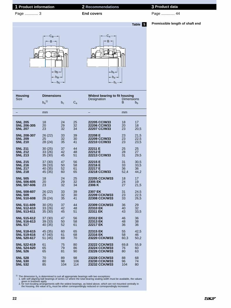
5 Premissible length of shaft end
22
1 Product information 2 Recommendations 3 Product data
Page ............. 3 End covers Page ............. 44
B
Ca
bc
bb
ba
B
Ca
bc
bb
ba
Table
8
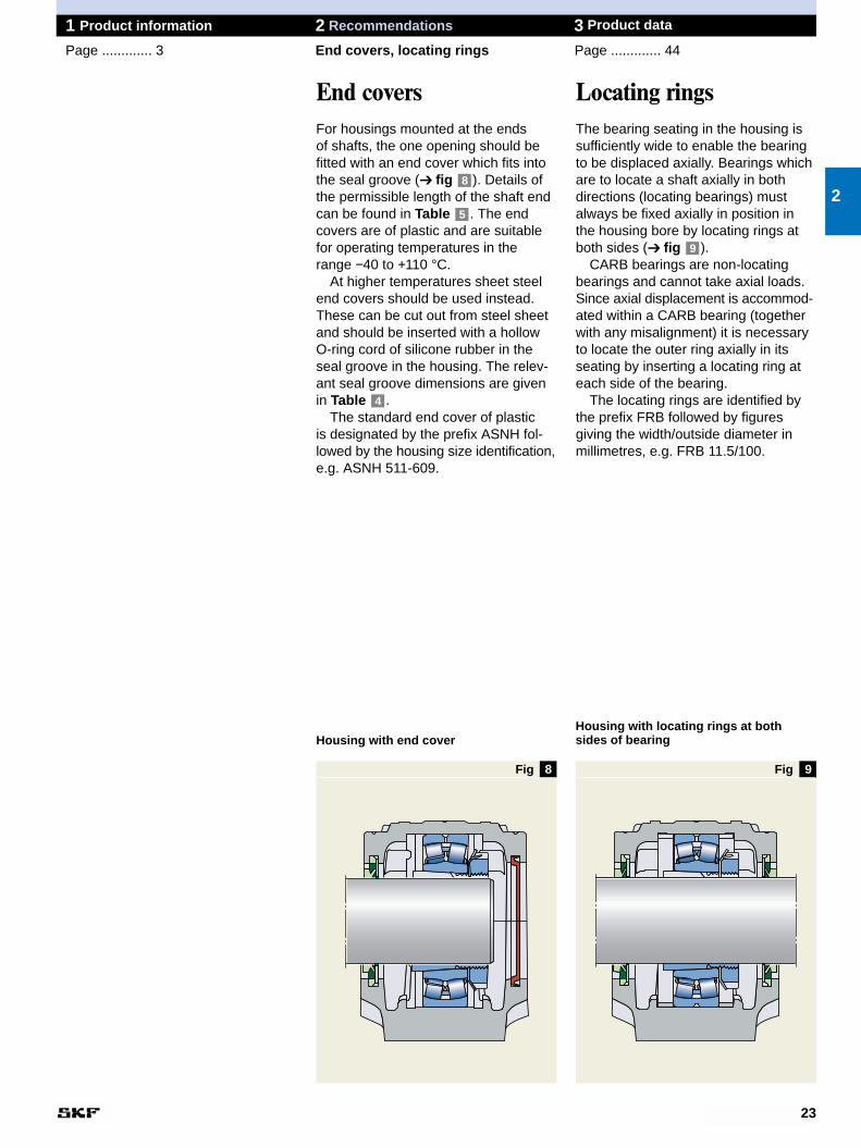
Locating ringsThe bearing seating in the housing issufficiently wide to enable the bearingto be displaced axially. Bearings whichare to locate a shaft axially in bothdirections (locating bearings) mustalways be fixed axially in position inthe housing bore by locating rings atboth sides (➔ fig ).
CARB bearings are non-locatingbearings and cannot take axial loads.Since axial displacement is accommod-ated within a CARB bearing (togetherwith any misalignment) it is necessaryto locate the outer ring axially in itsseating by inserting a locating ring ateach side of the bearing.
The locating rings are identified bythe prefix FRB followed by figures giving the width/outside diameter inmillimetres, e.g. FRB 11.5/100.
9
23
1 Product information 2 Recommendations 3 Product data
Page ............. 3 End covers, locating rings Page ............. 44
End coversFor housings mounted at the ends of shafts, the one opening should befitted with an end cover which fits intothe seal groove (➔ fig ). Details ofthe permissible length of the shaft endcan be found in Table . The endcovers are of plastic and are suitablefor operating temperatures in therange −40 to +110 °C.
At higher temperatures sheet steelend covers should be used instead.These can be cut out from steel sheetand should be inserted with a hollowO-ring cord of silicone rubber in theseal groove in the housing. The relev-ant seal groove dimensions are givenin Table .
The standard end cover of plastic is designated by the prefix ASNH fol-lowed by the housing size identification,e.g. ASNH 511-609.
4
5
82
9Fig Fig
Housing with end coverHousing with locating rings at bothsides of bearing
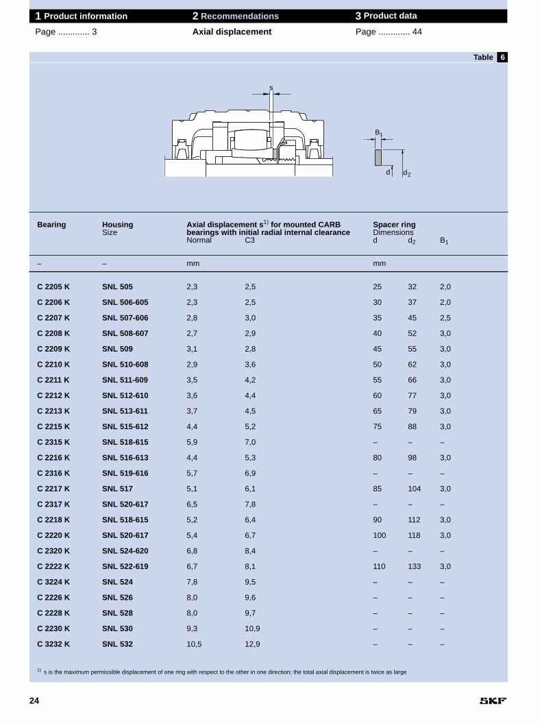
Bearing Housing Axial displacement s1) for mounted CARB Spacer ringSize bearings with initial radial internal clearance Dimensions
Normal C3 d d2 B1
– – mm mm
C 2205 K SNL 505 2,3 2,5 25 32 2,0
C 2206 K SNL 506-605 2,3 2,5 30 37 2,0
C 2207 K SNL 507-606 2,8 3,0 35 45 2,5
C 2208 K SNL 508-607 2,7 2,9 40 52 3,0
C 2209 K SNL 509 3,1 2,8 45 55 3,0
C 2210 K SNL 510-608 2,9 3,6 50 62 3,0
C 2211 K SNL 511-609 3,5 4,2 55 66 3,0
C 2212 K SNL 512-610 3,6 4,4 60 77 3,0
C 2213 K SNL 513-611 3,7 4,5 65 79 3,0
C 2215 K SNL 515-612 4,4 5,2 75 88 3,0
C 2315 K SNL 518-615 5,9 7,0 – – –
C 2216 K SNL 516-613 4,4 5,3 80 98 3,0
C 2316 K SNL 519-616 5,7 6,9 – – –
C 2217 K SNL 517 5,1 6,1 85 104 3,0
C 2317 K SNL 520-617 6,5 7,8 – – –
C 2218 K SNL 518-615 5,2 6,4 90 112 3,0
C 2220 K SNL 520-617 5,4 6,7 100 118 3,0
C 2320 K SNL 524-620 6,8 8,4 – – –
C 2222 K SNL 522-619 6,7 8,1 110 133 3,0
C 3224 K SNL 524 7,8 9,5 – – –
C 2226 K SNL 526 8,0 9,6 – – –
C 2228 K SNL 528 8,0 9,7 – – –
C 2230 K SNL 530 9,3 10,9 – – –
C 3232 K SNL 532 10,5 12,9 – – –
1) s is the maximum permissible displacement of one ring with respect to the other in one direction; the total axial displacement is twice as large
6
24
1 Product information 2 Recommendations 3 Product data
Page ............. 3 Axial displacement Page ............. 44
Table
s
B
d d
1
2
10
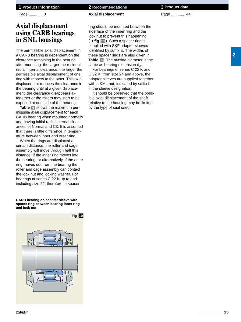
ring should be mounted between theside face of the inner ring and the lock nut to prevent this happening (➔ fig ). Such a spacer ring is supplied with SKF adapter sleevesidentified by suffix E. The widths ofthese spacer rings are also given inTable . The outside diameter is thesame as bearing dimension d2.
For bearings of series C 22 K and C 32 K, from size 24 and above, theadapter sleeves are supplied togetherwith a KML nut, indicated by suffix L in the sleeve designation.
It should be observed that the poss-ible axial displacement of the shaft relative to the housing may be limitedby the type of seal used.
6
10
25
1 Product information 2 Recommendations 3 Product data
Page ............. 3 Axial displacement Page ............. 44
2
Axial displacementusing CARB bearings in SNL housingsThe permissible axial displacement in a CARB bearing is dependent on theclearance remaining in the bearingafter mounting: the larger the residualradial internal clearance, the larger thepermissible axial displacement of onering with respect to the other. This axialdisplacement reduces the clearance inthe bearing until at a given displace-ment, the clearance disappears al-together or the rollers may start to beexposed at one side of the bearing.
Table shows the maximum per-missible axial displacement for eachCARB bearing when mounted normallyand having initial radial internal clear-ances of Normal and C3. It is assumedthat there is little difference in temper-ature between inner and outer ring.
When the rings are displaced a certain distance, the roller and cageassembly will move through half thisdistance. If the inner ring moves intothe bearing, or alternatively, if the outerring moves out from the bearing theroller and cage assembly can contactthe lock nut and locking washer. Forbearings of series C 22 K up to andincluding size 22, therefore, a spacer
6
CARB bearing on adapter sleeve withspacer ring between bearing inner ringand lock nut
Fig
Application advice for trouble-free operation
26
1 Product information 2 Recommendations 3 Product data
Page ............. 3 Trouble-free operation Page ............. 44
Condition monitoring is recommendedfor SNL plummer blocks particularly if they are used on machines wherefailures would cause production stop-pages. The early recognition and trend-ing of the degradation of the machineand machine parts make it possible toanalyse the cause and to be able toplan for corrective maintenanceactions in good time.
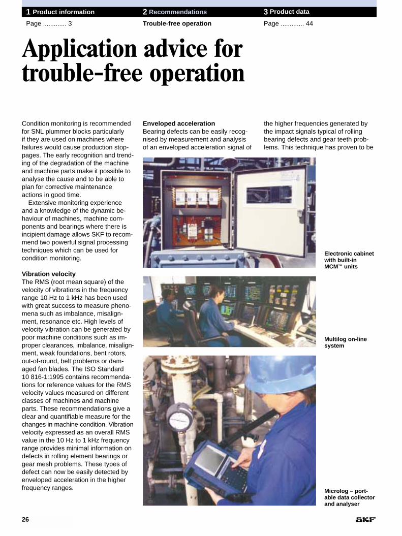
Extensive monitoring experienceand a knowledge of the dynamic be-haviour of machines, machine com-ponents and bearings where there is incipient damage allows SKF to recom-mend two powerful signal processingtechniques which can be used for condition monitoring.
Vibration velocityThe RMS (root mean square) of thevelocity of vibrations in the frequencyrange 10 Hz to 1 kHz has been usedwith great success to measure pheno-mena such as imbalance, misalign-ment, resonance etc. High levels ofvelocity vibration can be generated bypoor machine conditions such as im-proper clearances, imbalance, misalign-ment, weak foundations, bent rotors,out-of-round, belt problems or dam-aged fan blades. The ISO Standard 10 816-1:1995 contains recommenda-tions for reference values for the RMSvelocity values measured on differentclasses of machines and machineparts. These recommendations give aclear and quantifiable measure for thechanges in machine condition. Vibrationvelocity expressed as an overall RMSvalue in the 10 Hz to 1 kHz frequencyrange provides minimal information ondefects in rolling element bearings orgear mesh problems. These types ofdefect can now be easily detected byenveloped acceleration in the higherfrequency ranges.
Enveloped accelerationBearing defects can be easily recog-nised by measurement and analysis of an enveloped acceleration signal of
the higher frequencies generated bythe impact signals typical of rollingbearing defects and gear teeth prob-lems. This technique has proven to be
Electronic cabinetwith built-inMCM™ units
Multilog on-linesystem
Microlog – port-able data collectorand analyser
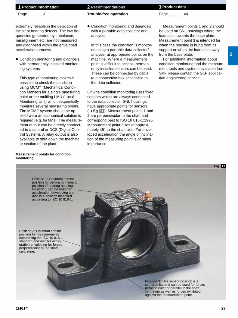
Measurement points 1 and 2 shouldbe used on SNL housings where theload acts towards the base plate.Measurement point 3 is intended forwhen the housing is hung from its support or when the load acts awayfrom the base plate.
For additional information about condition monitoring and the measure-ment tools and systems available fromSKF please contact the SKF applica-tion engineering service.
27
1 Product information 2 Recommendations 3 Product data
Page ............. 3 Trouble-free operation Page ............. 44
extremely reliable in the detection ofincipient bearing defects. The low fre-quencies generated by imbalance,misalignment etc. are not measuredand diagnosed within the envelopedacceleration process.
● Condition monitoring and diagnosiswith permanently installed monitor-ing systems
This type of monitoring makes it possible to check the condition using MCM™ (Mechanical Condi-tion Monitor) for a single measuringpoint or the multilog LMU (LocalMonitoring Unit) which sequentiallymonitors several measuring points.The MCM™ system should be ap-plied were an economical solution isrequired (e.g. for fans). The measure-ment output can be directly connect-ed to a control or DCS (Digital Con-trol System). A relay output is alsoavailable to shut down the machineor section of the plant.
2
● Condition monitoring and diagnosiswith a portable data collector andanalyser
In this case the condition is monitor-ed using a portable data collector/analyser at appropriate points on themachine. Where a measurementpoint is difficult to access, perman-ently installed sensors can be used.These can be connected by cable to a connection box accessible tothe data collector.
On-line condition monitoring uses fixedsensors which are always connected to the data collector. SNL housingshave appropriate points for sensors (➔ fig ). Measurement points 1 and2 are perpendicular to the shaft andcorrespond best to ISO 10 816-1:1995.Measurement point 3 lies at approxi-mately 45° to the shaft axis. For enve-loped acceleration the angle of inclina-tion of the measuring point is of minorimportance.
11
11Fig
Measurement points for condition monitoring
Position 1: Optimum sensorposition for vertical or hangingposition of bearing housing.Position 1 can be used foracceleration enveloping andalso is a position identifiedaccording to ISO 10 816-1.
Position 2: Optimum sensorposition for measurementsconcerning the ISO 10 816-1standard and also for accel-eration enveloping for forcesperpendicular to the shaftcentreline.
Position 3: This sensor position is acompromise and can be used for forcesperpendicular or parallel to the shaftcentreline as well as forces exhibitedagainst the measurement point.
Housing Grease quantitiesSize First Relub-
fill1) rication
– g
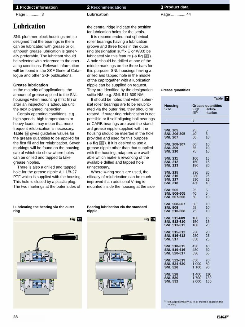
SNL 205 25 5SNL 206-305 40 5SNL 207 50 10
SNL 208-307 60 10SNL 209 65 10SNL 210 75 10
SNL 211 100 15SNL 212 150 15SNL 213 180 20
SNL 215 230 20SNL 216 280 25SNL 217 330 25SNL 218 430 40
SNL 505 25 5SNL 506-605 40 5SNL 507-606 50 10
SNL 508-607 60 10SNL 509 65 10SNL 510-608 75 10
SNL 511-609 100 15SNL 512-610 150 15SNL 513-611 180 20
SNL 515-612 230 20SNL 516-613 280 25SNL 517 330 25
SNL 518-615 430 40SNL 519-616 480 50SNL 520-617 630 55
SNL 522-619 850 70SNL 524-620 1 000 80SNL 526 1 100 95
SNL 528 1 400 110SNL 530 1 700 130SNL 532 2 000 150
1) Fills approximately 40 % of the free space in thehousing
7
the central ridge indicate the positionfor lubrication holes for the seals.
It is recommended that spherical roller bearings having a lubricationgroove and three holes in the outerring (designation suffix E or W33) belubricated via this feature (➔ fig ).A hole should be drilled at one of themiddle markings on the three bars forthis purpose. SNL housings having adrilled and tapped hole in the middle of the cap together with a lubricationnipple can be supplied on request.They are identified by the designationsuffix NM, e.g. SNL 511-609 NM.
It should be noted that when spher-ical roller bearings are to be relubric-ated via the outer ring, they should berotated. If outer ring relubrication is notpossible or if self-aligning ball bearingsor CARB bearings are used the stand-ard grease nipple supplied with thehousing should be inserted in the holeprovided and used for this purpose (➔ fig ). If it is desired to use a grease nipple other than that suppliedwith the housing, adapters are avail-able which make a reworking of theavailable drilled and tapped hole unnecessary.
Where V-ring seals are used, theefficacy of relubrication can be muchimproved if an additional V-ring ismounted inside the housing at the side
13
12
28
1 Product information 2 Recommendations 3 Product data
Page ............. 3 Lubrication Page ............. 44
LubricationSNL plummer block housings are sodesigned that the bearings in them can be lubricated with grease or oil,although grease lubrication is gener-ally preferable. The lubricant should be selected with reference to the oper-ating conditions. Relevant informationwill be found in the SKF General Cata-logue and other SKF publications.
Grease lubricationIn the majority of applications, theamount of grease applied to the SNLhousings when mounting (first fill) orafter an inspection is adequate untilthe next planned inspection.
Certain operating conditions, e.g.high speeds, high temperatures orheavy loads, may mean that more frequent relubrication is necessary.Table gives guideline values for the grease quantities to be applied forthe first fill and for relubrication. Sevenmarkings will be found on the housingcap of which six show where holes can be drilled and tapped to take grease nipples.
There is also a drilled and tappedhole for the grease nipple AH 1/8-27PTF which is supplied with the housing.This hole is closed by a plastic plug.The two markings at the outer sides of
7
Lubricating the bearing via the outer ring
12 13Fig Fig
Table
Bearing lubrication via the standard nipple
Grease quantities
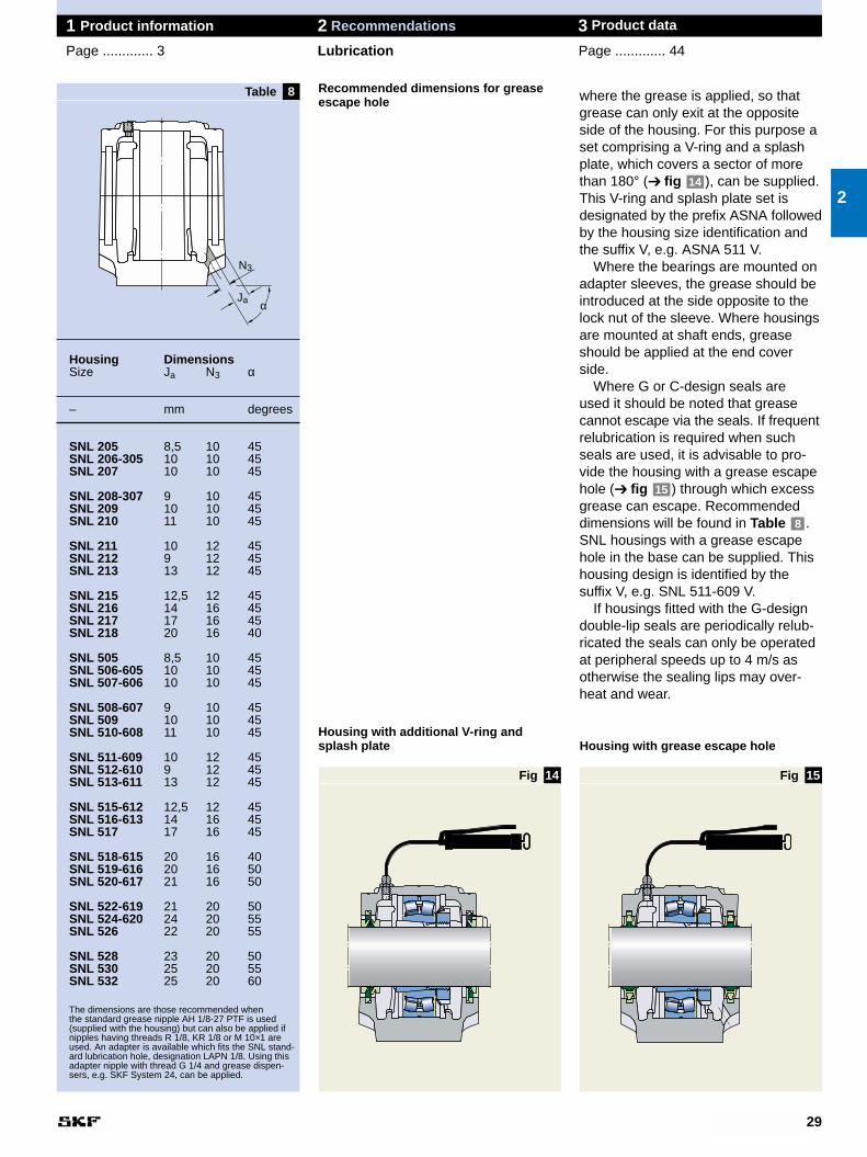
Housing DimensionsSize Ja N3 α
– mm degrees
SNL 205 8,5 10 45SNL 206-305 10 10 45SNL 207 10 10 45
SNL 208-307 9 10 45SNL 209 10 10 45SNL 210 11 10 45
SNL 211 10 12 45SNL 212 9 12 45SNL 213 13 12 45
SNL 215 12,5 12 45SNL 216 14 16 45SNL 217 17 16 45SNL 218 20 16 40
SNL 505 8,5 10 45SNL 506-605 10 10 45SNL 507-606 10 10 45
SNL 508-607 9 10 45SNL 509 10 10 45SNL 510-608 11 10 45
SNL 511-609 10 12 45SNL 512-610 9 12 45SNL 513-611 13 12 45
SNL 515-612 12,5 12 45SNL 516-613 14 16 45SNL 517 17 16 45
SNL 518-615 20 16 40SNL 519-616 20 16 50SNL 520-617 21 16 50
SNL 522-619 21 20 50SNL 524-620 24 20 55SNL 526 22 20 55
SNL 528 23 20 50SNL 530 25 20 55SNL 532 25 20 60
The dimensions are those recommended when the standard grease nipple AH 1/8-27 PTF is used(supplied with the housing) but can also be applied ifnipples having threads R 1/8, KR 1/8 or M 10×1 areused. An adapter is available which fits the SNL stand-ard lubrication hole, designation LAPN 1/8. Using thisadapter nipple with thread G 1/4 and grease dispen-sers, e.g. SKF System 24, can be applied.
14
8 Recommended dimensions for greaseescape hole
29
1 Product information 2 Recommendations 3 Product data
Page ............. 3 Lubrication Page ............. 44
2
15
where the grease is applied, so thatgrease can only exit at the oppositeside of the housing. For this purpose aset comprising a V-ring and a splashplate, which covers a sector of morethan 180° (➔ fig ), can be supplied.This V-ring and splash plate set is designated by the prefix ASNA followedby the housing size identification andthe suffix V, e.g. ASNA 511 V.
Where the bearings are mounted onadapter sleeves, the grease should beintroduced at the side opposite to thelock nut of the sleeve. Where housingsare mounted at shaft ends, greaseshould be applied at the end coverside.
Where G or C-design seals are used it should be noted that greasecannot escape via the seals. If frequentrelubrication is required when suchseals are used, it is advisable to pro-vide the housing with a grease escapehole (➔ fig ) through which excess grease can escape. Recommendeddimensions will be found in Table .SNL housings with a grease escapehole in the base can be supplied. Thishousing design is identified by the suffix V, e.g. SNL 511-609 V.
If housings fitted with the G-designdouble-lip seals are periodically relub-ricated the seals can only be operatedat peripheral speeds up to 4 m/s asotherwise the sealing lips may over-heat and wear.
8
15
14
Housing with additional V-ring andsplash plate Housing with grease escape hole
Fig Fig
Table
Ja
N3
α
16
MountingSNL housings together with SKF bearings are robust and operationallyreliable bearing arrangements whichhave long lives. However, if they are to achieve their full potential and notfail prematurely they must be properlymounted. Incorrect procedures orunsuitable tools can influence life negatively.
Mounting the bearingThe bearings can be mounted eitheron a tapered seating – normally forSNL housings in the form of an adap-ter sleeve – or on a cylindrical seating.When a bearing is correctly mountedon a sleeve there will be interferencefits between the inner ring, sleeve andshaft. The degree of interference isdetermined by how far the bearing isdriven up on the sleeve and either theinternal clearance reduction or theaxial drive-up distance can be used asa measure. The clearance reduction inspherical roller bearings can be meas-ured using a feeler gauge, or the newSKF drive-up method can be used.Information will be sent on request.
When mounting self-aligning ballbearings having Normal radial internalclearance (which is relatively small) theclearance reduction can be checkedby turning and swivelling out the outerring. When the swivelling out meets aslight resistance, the bearing has asufficient degree of interference andthe drive-up should be stopped. A par-ticularly simple method of mountingself-aligning ball bearings on adaptersleeves is the use of the spanner setTMHN 7 which has been speciallydeveloped for this purpose. Eachspanner is marked with the anglethough which the lock nut should beturned when self-aligning ball bearingshaving C3 radial internal clearance are used.
CARB bearings can also be mount-ed on cylindrical as well as taperedseatings. For tapered seatings, againnormally adapter sleeves, the spannerset TMHN 7 can be used for smallerCARB bearings as well as for self-aligning ball bearings. For larger CARBbearings either the clearance reduc-tion or the axial drive-up length shouldbe measured. When using a feeler
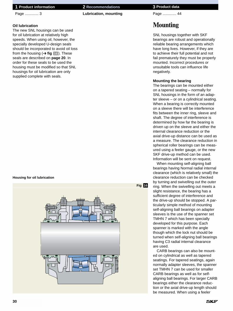
Oil lubricationThe new SNL housings can be usedfor oil lubrication at relatively highspeeds. When using oil, however, thespecially developed U-design sealsshould be incorporated to avoid oil lossfrom the housing (➔ fig ). Theseseals are described on page 20. Inorder for these seals to be used thehousing must be modified so that SNLhousings for oil lubrication are onlysupplied complete with seals.
16
30
1 Product information 2 Recommendations 3 Product data
Page ............. 3 Lubrication, mounting Page ............. 44
Housing for oil lubrication
Fig
Housing Dimensions Housing DimensionsSize J6 J7 N4 Size J6 J7 N4
max max
– mm – mm
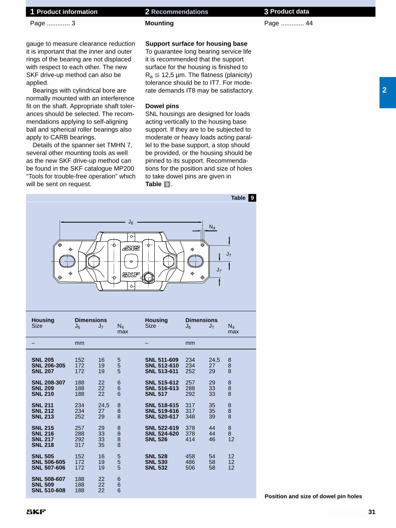
SNL 205 152 16 5 SNL 511-609 234 24,5 8SNL 206-305 172 19 5 SNL 512-610 234 27 8SNL 207 172 19 5 SNL 513-611 252 29 8
SNL 208-307 188 22 6 SNL 515-612 257 29 8SNL 209 188 22 6 SNL 516-613 288 33 8SNL 210 188 22 6 SNL 517 292 33 8
SNL 211 234 24,5 8 SNL 518-615 317 35 8SNL 212 234 27 8 SNL 519-616 317 35 8SNL 213 252 29 8 SNL 520-617 348 39 8
SNL 215 257 29 8 SNL 522-619 378 44 8SNL 216 288 33 8 SNL 524-620 378 44 8SNL 217 292 33 8 SNL 526 414 46 12SNL 218 317 35 8
SNL 505 152 16 5 SNL 528 458 54 12SNL 506-605 172 19 5 SNL 530 486 58 12SNL 507-606 172 19 5 SNL 532 506 58 12
SNL 508-607 188 22 6SNL 509 188 22 6SNL 510-608 188 22 6
9
Support surface for housing baseTo guarantee long bearing service lifeit is recommended that the supportsurface for the housing is finished toRa � 12,5 µm. The flatness (planicity)tolerance should be to IT7. For mode-rate demands IT8 may be satisfactory.
Dowel pinsSNL housings are designed for loadsacting vertically to the housing basesupport. If they are to be subjected tomoderate or heavy loads acting paral-lel to the base support, a stop shouldbe provided, or the housing should bepinned to its support. Recommenda-tions for the position and size of holesto take dowel pins are given in Table .9
31
1 Product information 2 Recommendations 3 Product data
Page ............. 3 Mounting Page ............. 44
gauge to measure clearance reductionit is important that the inner and outerrings of the bearing are not displacedwith respect to each other. The newSKF drive-up method can also beapplied.
Bearings with cylindrical bore arenormally mounted with an interferencefit on the shaft. Appropriate shaft toler-ances should be selected. The recom-mendations applying to self-aligningball and spherical roller bearings alsoapply to CARB bearings.
Details of the spanner set TMHN 7,several other mounting tools as well as the new SKF drive-up method canbe found in the SKF catalogue MP200“Tools for trouble-free operation” whichwill be sent on request.
2
Position and size of dowel pin holes
J7
J6
J7
N4
Table
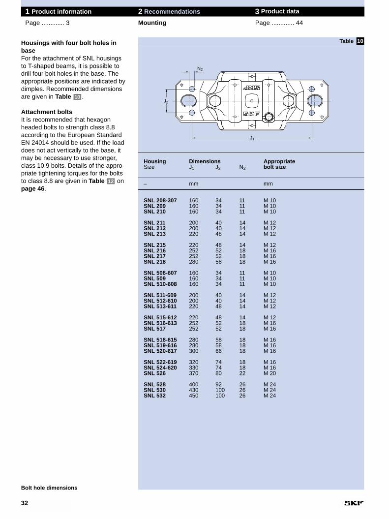
Housing Dimensions AppropriateSize J1 J2 N2 bolt size
– mm mm
SNL 208-307 160 34 11 M 10SNL 209 160 34 11 M 10SNL 210 160 34 11 M 10
SNL 211 200 40 14 M 12SNL 212 200 40 14 M 12SNL 213 220 48 14 M 12
SNL 215 220 48 14 M 12SNL 216 252 52 18 M 16SNL 217 252 52 18 M 16SNL 218 280 58 18 M 16
SNL 508-607 160 34 11 M 10SNL 509 160 34 11 M 10SNL 510-608 160 34 11 M 10
SNL 511-609 200 40 14 M 12SNL 512-610 200 40 14 M 12SNL 513-611 220 48 14 M 12
SNL 515-612 220 48 14 M 12SNL 516-613 252 52 18 M 16SNL 517 252 52 18 M 16
SNL 518-615 280 58 18 M 16SNL 519-616 280 58 18 M 16SNL 520-617 300 66 18 M 16
SNL 522-619 320 74 18 M 16SNL 524-620 330 74 18 M 16SNL 526 370 80 22 M 20
SNL 528 400 92 26 M 24SNL 530 430 100 26 M 24SNL 532 450 100 26 M 24
10Housings with four bolt holes inbaseFor the attachment of SNL housings to T-shaped beams, it is possible todrill four bolt holes in the base. Theappropriate positions are indicated bydimples. Recommended dimensionsare given in Table .
Attachment boltsIt is recommended that hexagon headed bolts to strength class 8.8according to the European StandardEN 24014 should be used. If the loaddoes not act vertically to the base, itmay be necessary to use stronger,class 10.9 bolts. Details of the appro-priate tightening torques for the boltsto class 8.8 are given in Table onpage 46.
12
10
32
1 Product information 2 Recommendations 3 Product data
Page ............. 3 Mounting Page ............. 44
Bolt hole dimensions
Table
J2
J1
N2
33
1 Product information 2 Recommendations 3 Product data
Page ............. 3 Mounting Page ............. 44
2
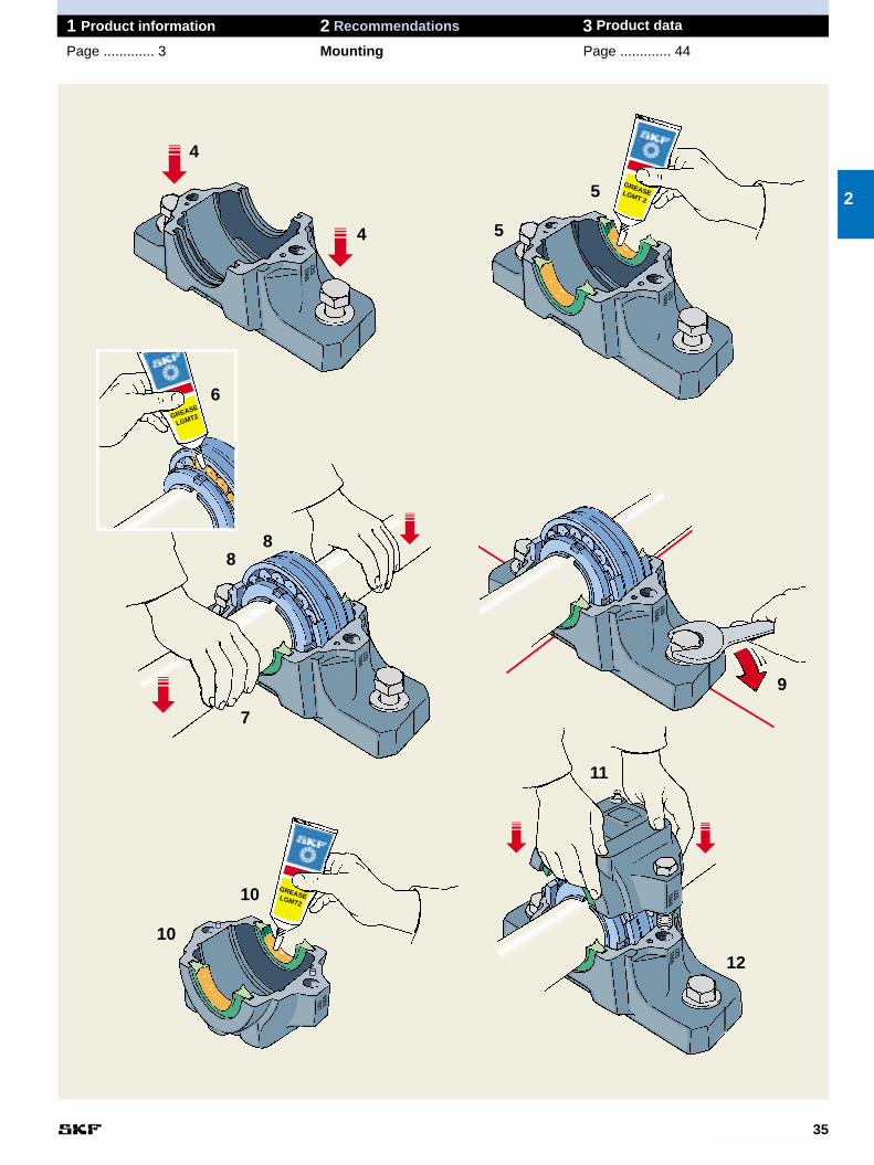
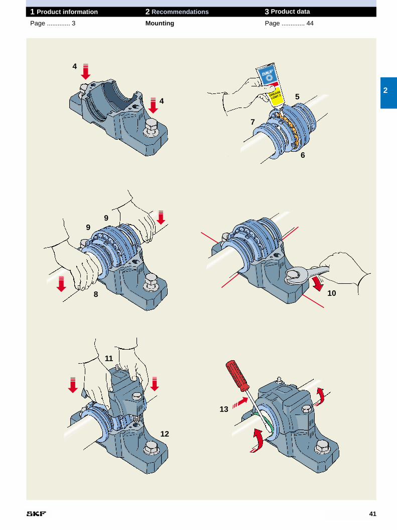
8. Put one locating ring (when needed)at each side of the bearing.
NB. Locating rings are only used forlocating bearing arrangements, exceptfor CARB bearings which, althoughalways non-locating, must always bemounted with locating rings.
9. Carefully align the housing base.Vertical markings at the middle of theside faces and ends of the housingbase can facilitate this. Then lightlytighten the attachment bolts.
10. The remaining seal halves shouldbe inserted in the seal grooves in thehousing cap and the space betweenthe sealing lips filled with grease.
11. The housing cap should be placedover the base and the cap bolts (to joincap and base) tightened to the torquespecified in Table on page 46. The cap and base of one housing arenot interchangeable with those of otherhousings. The cap and base should bechecked to see that they bear thesame identification.
12. Fully tighten the attachment boltsin the housing base. Recommendedtightening torques are given in Table on page 46.12
12
34
1 Product information 2 Recommendations 3 Product data
Page ............. 3 Mounting Page ............. 44
Mounting SNL housings with double-lipsealsBefore starting installation work, thefollowing instructions should be care-fully read.
1. Ensure that the environment is clean. Check the dimensional and form accur-acy of the shaft seating.
2. Check that the surface roughness of the support surface Ra � 12,5 µm.The flatness (planicity) toleranceshould be to IT7. For moderatedemands IT8 may be satisfactory.
3. If the bearing is mounted on anadapter sleeve, determine the positionof the housing. The grease nipplearranged at one side of the housingcap (for improved lubrication) shouldalways be at the side opposite to thesleeve nut. It is necessary to considerthe complete housing as the base andcap will only fit together as supplied.
4. Position the housing on the supportsurface. Fit the attachment bolts but do not tighten them.
5. Insert one seal half in each of thegrooves in the housing base. Fill thespace between the two sealing lipswith grease. If the housing is to beused at the end of a shaft, insert anend cover at one side instead of theseal half.
6. Mount the bearing on the shaft – either directly on a stepped shaft orusing an adapter sleeve. Completelyfill the bearing with grease. The re-mainder of the recommended greasequantity should be put in the housingbase at the sides (➔ Table , page 28).
7. Lay the shaft with bearing in thehousing base.
7
35
1 Product information 2 Recommendations 3 Product data
Page ............. 3 Mounting Page ............. 44
2
0001 S2
7
GREASELGMT 2
0001 S2
7
0001 S2
7
0001 S2
7
GREASELGMT2
0001S27
0001 S2
7
0001 S2
7
4
4
8
7
9
10
10
11
12
8
5
5
GREASE
LGMT2
6
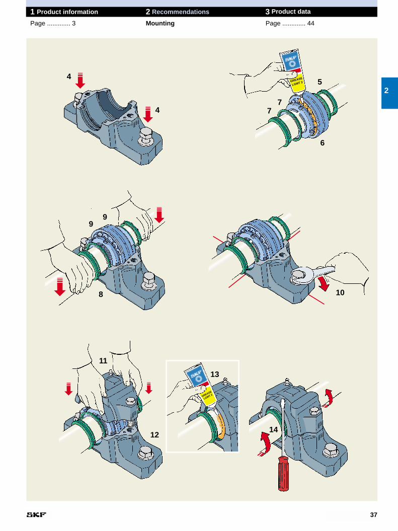
8. Lay the shaft with bearing and seal-ing washers in the housing base.
9. Put one locating ring (when needed)at each side of the bearing.
NB. Locating rings are only used forlocating bearing arrangements, exceptfor CARB bearings which, althoughalways non-locating, must always bemounted with locating rings.
10. Carefully align the housing base.Vertical markings at the middle of theside faces and ends of the housingbase can facilitate this. Then lightlytighten the attachment bolts.
11. The housing cap should be placedover the base and the cap bolts (to joincap and base) tightened to the torquespecified in Table on page 46. The cap and base of one housing arenot interchangeable with those of otherhousings. The cap and base should bechecked to see that they bear thesame identification.
12. Fully tighten the attachment boltsin the housing base. Recommendedtightening torques are given in Table on page 46.
13. Coat the V-ring counterfaces onthe sealing washers with grease.
14. Finally, push the V-ring seals intotheir correct position. This can be doneusing a screwdriver at the same timeas the shaft is turned.
12
12
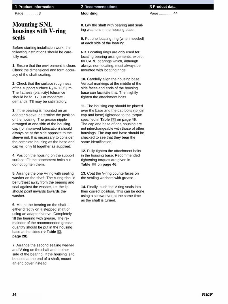
Mounting SNL housings with V-ringsealsBefore starting installation work, thefollowing instructions should be care-fully read.
1. Ensure that the environment is clean.Check the dimensional and form accur-acy of the shaft seating.
2. Check that the surface roughness of the support surface Ra � 12,5 µm. The flatness (planicity) toleranceshould be to IT7. For moderatedemands IT8 may be satisfactory.
3. If the bearing is mounted on anadapter sleeve, determine the positionof the housing. The grease nipplearranged at one side of the housingcap (for improved lubrication) shouldalways be at the side opposite to thesleeve nut. It is necessary to considerthe complete housing as the base andcap will only fit together as supplied.
4. Position the housing on the supportsurface. Fit the attachment bolts but do not tighten them.
5. Arrange the one V-ring with sealingwasher on the shaft. The V-ring shouldbe furthest away from the bearing andseal against the washer, i.e. the lipshould point inwards towards thewasher.
6. Mount the bearing on the shaft – either directly on a stepped shaft orusing an adapter sleeve. Completelyfill the bearing with grease. The re-mainder of the recommended greasequantity should be put in the housingbase at the sides (➔ Table , page 28).
7. Arrange the second sealing washerand V-ring on the shaft at the otherside of the bearing. If the housing is tobe used at the end of a shaft, mountan end cover instead.
7
36
1 Product information 2 Recommendations 3 Product data
Page ............. 3 Mounting Page ............. 44
37
1 Product information 2 Recommendations 3 Product data
Page ............. 3 Mounting Page ............. 44
2
0001 S2
7
GREASE
LGMT 2
0001 S2
7
0001 S2
7
0001 S2
7
0001 S2
7
0001 S2
7
0001 S2
7
GREASE
LGMT 2
4
4
5
6
8 10
11
12
13
14
99
77
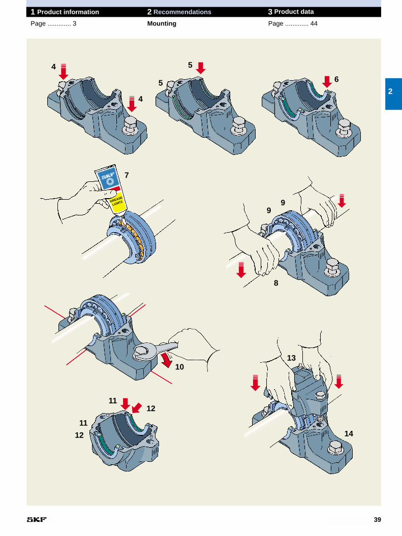
8. Lay the shaft with bearing in thehousing base.
9. Put one locating ring (when needed)at each side of the bearing.
NB. Locating rings are only used forlocating bearing arrangements, exceptfor CARB bearings which, althoughalways non-locating, must always bemounted with locating rings.
10. Carefully align the housing base.Vertical markings at the middle of theside faces and ends of the housingbase can facilitate this. Then lightlytighten the attachment bolts.
11. Put the O-ring cord into the sealinggrooves in the housing cap.
12. The remaining seal halves shouldbe inserted in the seal grooves in thehousing cap over the O-ring cords.
13. The housing cap should be placedover the base and the cap bolts (to joincap and base) tightened to the torquespecified in Table on page 46. The cap and base of one housing arenot interchangeable with those of otherhousings. The cap and base should bechecked to see that they bear thesame identification.
14. Fully tighten the attachment boltsin the housing base. Recommendedtightening torques are given in Table on page 46.12
12
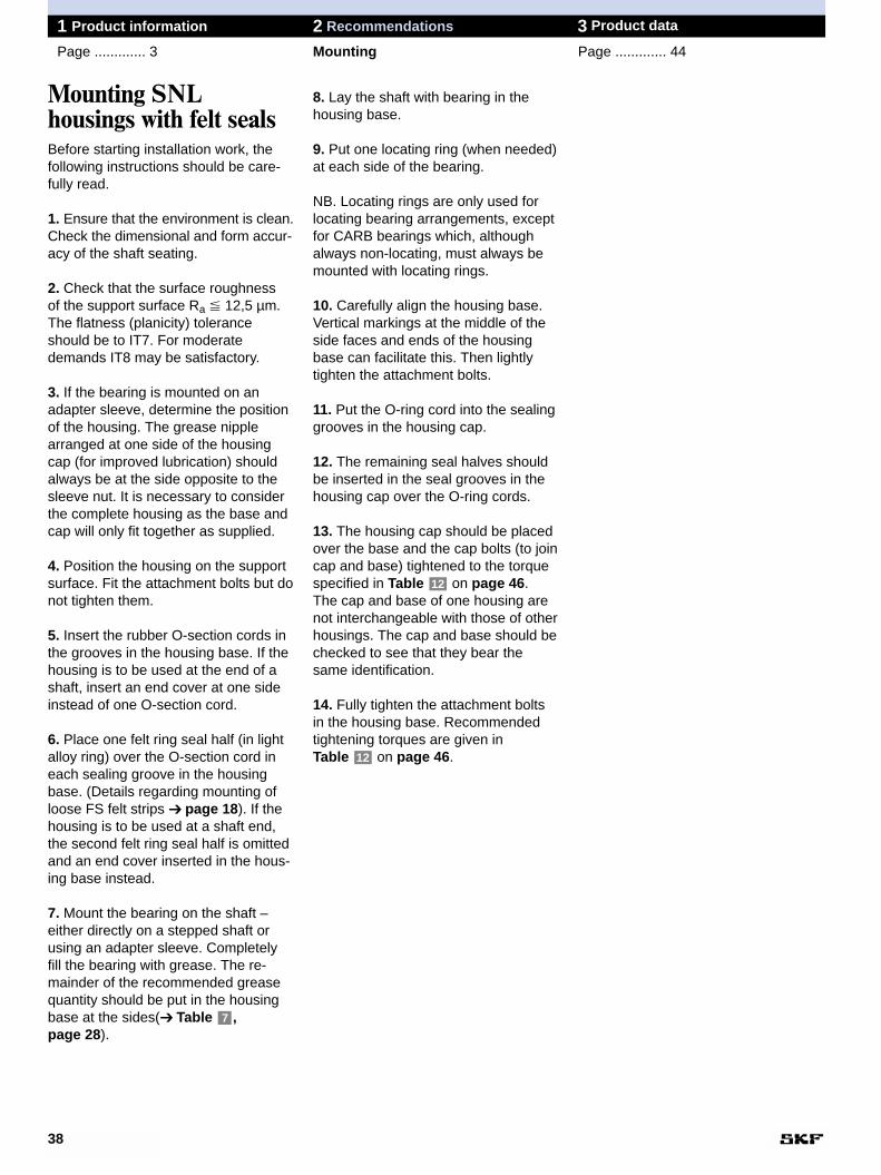
Mounting SNL housings with felt sealsBefore starting installation work, thefollowing instructions should be care-fully read.
1. Ensure that the environment is clean.Check the dimensional and form accur-acy of the shaft seating.
2. Check that the surface roughness of the support surface Ra � 12,5 µm.The flatness (planicity) toleranceshould be to IT7. For moderatedemands IT8 may be satisfactory.
3. If the bearing is mounted on anadapter sleeve, determine the positionof the housing. The grease nipplearranged at one side of the housingcap (for improved lubrication) shouldalways be at the side opposite to thesleeve nut. It is necessary to considerthe complete housing as the base andcap will only fit together as supplied.
4. Position the housing on the supportsurface. Fit the attachment bolts but donot tighten them.
5. Insert the rubber O-section cords inthe grooves in the housing base. If thehousing is to be used at the end of ashaft, insert an end cover at one sideinstead of one O-section cord.
6. Place one felt ring seal half (in lightalloy ring) over the O-section cord ineach sealing groove in the housingbase. (Details regarding mounting ofloose FS felt strips ➔ page 18). If thehousing is to be used at a shaft end,the second felt ring seal half is omittedand an end cover inserted in the hous-ing base instead.
7. Mount the bearing on the shaft – either directly on a stepped shaft orusing an adapter sleeve. Completelyfill the bearing with grease. The re-mainder of the recommended greasequantity should be put in the housingbase at the sides(➔ Table , page 28).
7
38
1 Product information 2 Recommendations 3 Product data
Page ............. 3 Mounting Page ............. 44
39
1 Product information 2 Recommendations 3 Product data
Page ............. 3 Mounting Page ............. 44
2
0001 S2
7
0001 S2
7
0001 S2
7
GREASE
LGMT2
0001 S2
7
0001 S2
7
0001S27
0001 S2
7
0001 S2
7
4
4
5
6
7
8
10
11
11
12
12
13
14
5
99
9. Put one locating ring (when needed)at each side of the bearing.
NB. Locating rings are only used forlocating bearing arrangements, exceptfor CARB bearings which, althoughalways non-locating, must always bemounted with locating rings.
10. Carefully align the housing base.Vertical markings at the middle of theside faces and ends of the housingbase can facilitate this. Then lightlytighten the attachment bolts.
11. The housing cap should be placedover the base and the cap bolts (to joincap and base) tightened to the torquespecified in Table on page 46. The cap and base of one housing arenot interchangeable with those of otherhousings. The cap and base should bechecked to see that they bear thesame identification.
12. Fully tighten the attachment boltsin the housing base. Recommendedtightening torques are given in Table on page 46.
13. Finally insert the hollow O-ringcord of synthetic rubber in the groovesin the labyrinth rings. This can be doneusing a screwdriver while turning theshaft.
12
12
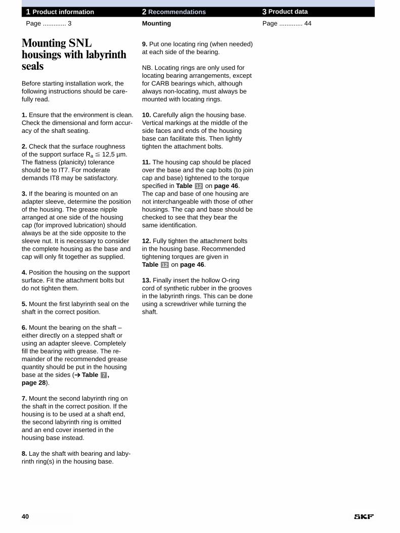
Mounting SNL housings with labyrinthsealsBefore starting installation work, thefollowing instructions should be care-fully read.
1. Ensure that the environment is clean.Check the dimensional and form accur-acy of the shaft seating.
2. Check that the surface roughness of the support surface Ra � 12,5 µm.The flatness (planicity) toleranceshould be to IT7. For moderatedemands IT8 may be satisfactory.
3. If the bearing is mounted on anadapter sleeve, determine the positionof the housing. The grease nipplearranged at one side of the housingcap (for improved lubrication) shouldalways be at the side opposite to thesleeve nut. It is necessary to considerthe complete housing as the base andcap will only fit together as supplied.
4. Position the housing on the supportsurface. Fit the attachment bolts but do not tighten them.
5. Mount the first labyrinth seal on theshaft in the correct position.
6. Mount the bearing on the shaft – either directly on a stepped shaft orusing an adapter sleeve. Completelyfill the bearing with grease. The re-mainder of the recommended greasequantity should be put in the housingbase at the sides (➔ Table , page 28).
7. Mount the second labyrinth ring onthe shaft in the correct position. If thehousing is to be used at a shaft end,the second labyrinth ring is omittedand an end cover inserted in the housing base instead.
8. Lay the shaft with bearing and laby-rinth ring(s) in the housing base.
7
40
1 Product information 2 Recommendations 3 Product data
Page ............. 3 Mounting Page ............. 44
41
1 Product information 2 Recommendations 3 Product data
Page ............. 3 Mounting Page ............. 44
2
0001 S2
7
GREASE
LGMT 2
0001 S2
7
0001 S2
7
0001 S2
7
0001 S2
7
0001 S2
7
0001 S2
7
4
4 5
6
99
8 10
11
12
13
7
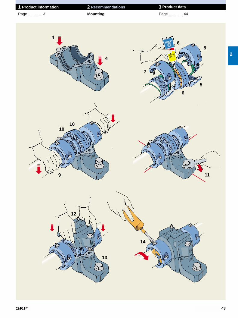
7. Mount the second seal according topoint 5. If the housing is to be used ata shaft end, the second seal is omittedand an end cover inserted in the hous-ing base instead.
8. Use the hollow O-section cord to fix the labyrinth ring in position on theshaft. A screwdriver can be used to fitthe cords whilst rotating the shaft. Mountthe O-ring on the seal outer diameter.
9. Lay the shaft with bearing and sealsin the housing base taking care thatthe O-rings are not damaged.
10. Put one locating ring (when need-ed) at each side of the bearing.
NB. Locating rings are only used forlocating bearing arrangements, exceptfor CARB bearings which, althoughalways non-locating, must always bemounted with locating rings.
11. Carefully align the housing base.Vertical markings at the middle of theside faces and ends of the housingbase can facilitate this. Then lightlytighten the attachment bolts.
12. The housing cap should be placedover the base and the cap bolts (to joincap and base) tightened to the torquespecified in Table on page 46. The cap and base of one housing arenot interchangeable with those of otherhousings. The cap and base should be checked to see that they bear thesame identification.
13. Fully tighten the attachment boltsin the housing base. Recommendedtightening torques are given in Table on page 46.
14. Finally, before the first test run,rotate the shaft and supply grease via the nipple until it exudes from thelabyrinth rings. The same grease asthat used for the bearing should alsobe used to lubricate the labyrinth rings.
12
12
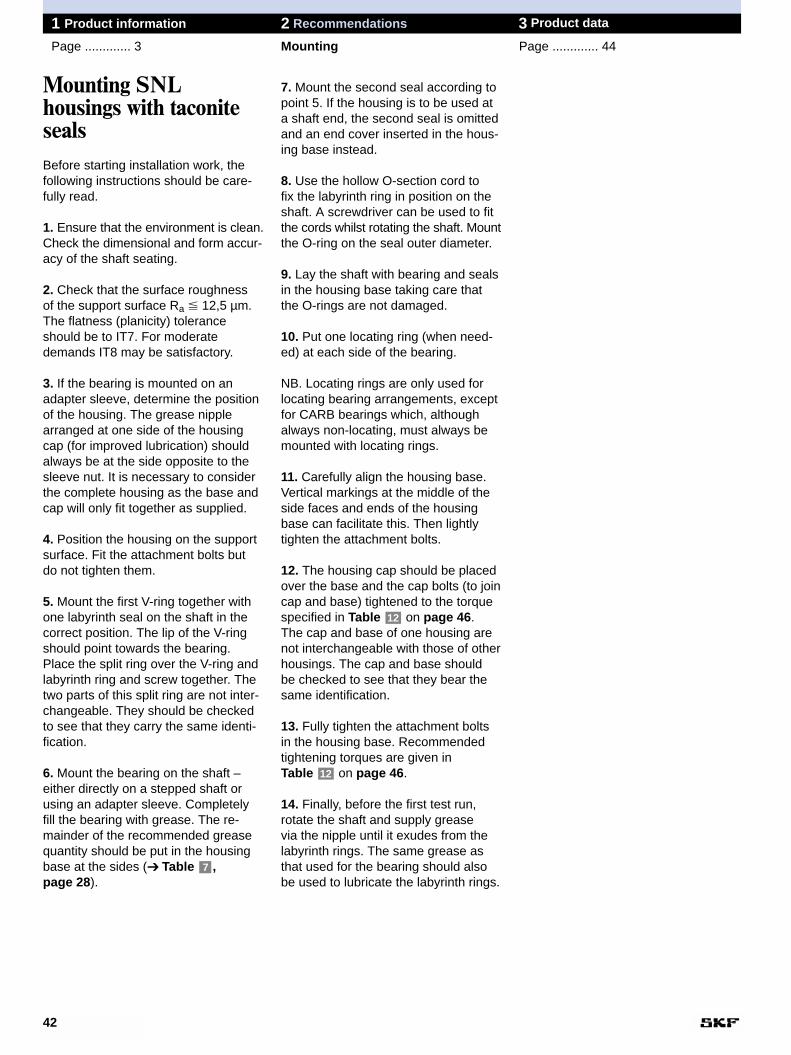
Mounting SNL housings with taconitesealsBefore starting installation work, thefollowing instructions should be care-fully read.
1. Ensure that the environment is clean.Check the dimensional and form accur-acy of the shaft seating.
2. Check that the surface roughness of the support surface Ra � 12,5 µm.The flatness (planicity) toleranceshould be to IT7. For moderatedemands IT8 may be satisfactory.
3. If the bearing is mounted on anadapter sleeve, determine the positionof the housing. The grease nipplearranged at one side of the housingcap (for improved lubrication) shouldalways be at the side opposite to thesleeve nut. It is necessary to considerthe complete housing as the base andcap will only fit together as supplied.
4. Position the housing on the supportsurface. Fit the attachment bolts but do not tighten them.
5. Mount the first V-ring together withone labyrinth seal on the shaft in thecorrect position. The lip of the V-ringshould point towards the bearing.Place the split ring over the V-ring andlabyrinth ring and screw together. Thetwo parts of this split ring are not inter-changeable. They should be checkedto see that they carry the same identi-fication.
6. Mount the bearing on the shaft – either directly on a stepped shaft orusing an adapter sleeve. Completelyfill the bearing with grease. The re-mainder of the recommended greasequantity should be put in the housingbase at the sides (➔ Table , page 28).
7
42
1 Product information 2 Recommendations 3 Product data
Page ............. 3 Mounting Page ............. 44
43
1 Product information 2 Recommendations 3 Product data
Page ............. 3 Mounting Page ............. 44
2
0001 S2
7
GREASE
LGMT 2
0001 S2
7
0001 S2
7
0001 S2
7
0001 S2
7
0001 S2
7
0001 S2
7
4
4
5
5
7
6
6
9 11
12
13
14
1010
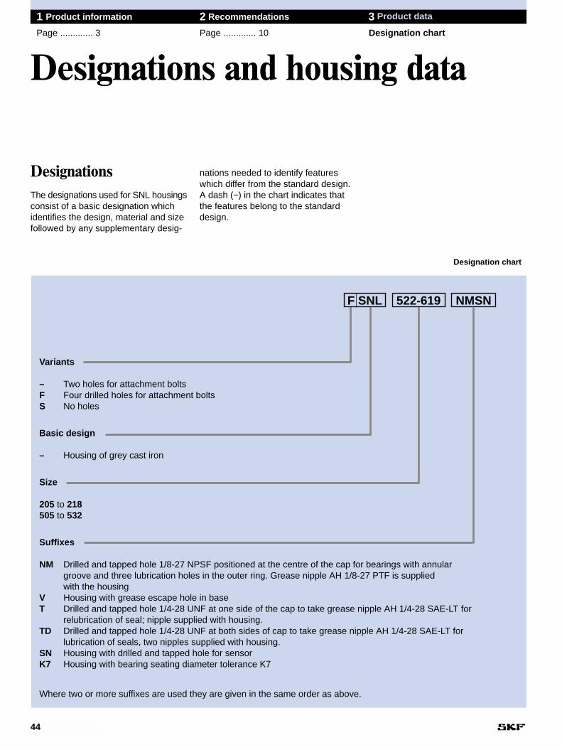
Variants
– Two holes for attachment boltsF Four drilled holes for attachment bolts S No holes
Basic design
– Housing of grey cast iron
Size
205 to 218505 to 532
Suffixes
NM Drilled and tapped hole 1/8-27 NPSF positioned at the centre of the cap for bearings with annular groove and three lubrication holes in the outer ring. Grease nipple AH 1/8-27 PTF is supplied with the housing
V Housing with grease escape hole in baseT Drilled and tapped hole 1/4-28 UNF at one side of the cap to take grease nipple AH 1/4-28 SAE-LT for
relubrication of seal; nipple supplied with housing.TD Drilled and tapped hole 1/4-28 UNF at both sides of cap to take grease nipple AH 1/4-28 SAE-LT for
lubrication of seals, two nipples supplied with housing.SN Housing with drilled and tapped hole for sensorK7 Housing with bearing seating diameter tolerance K7
Where two or more suffixes are used they are given in the same order as above.
nations needed to identify featureswhich differ from the standard design.A dash (−) in the chart indicates thatthe features belong to the standarddesign.
Designations and housing data
44
1 Product information 2 Recommendations 3 Product data
Page ............. 3 Page ............. 10 Designation chart
DesignationsThe designations used for SNL housingsconsist of a basic designation whichidentifies the design, material and sizefollowed by any supplementary desig-
Designation chart
522-619 NMSNF SNL
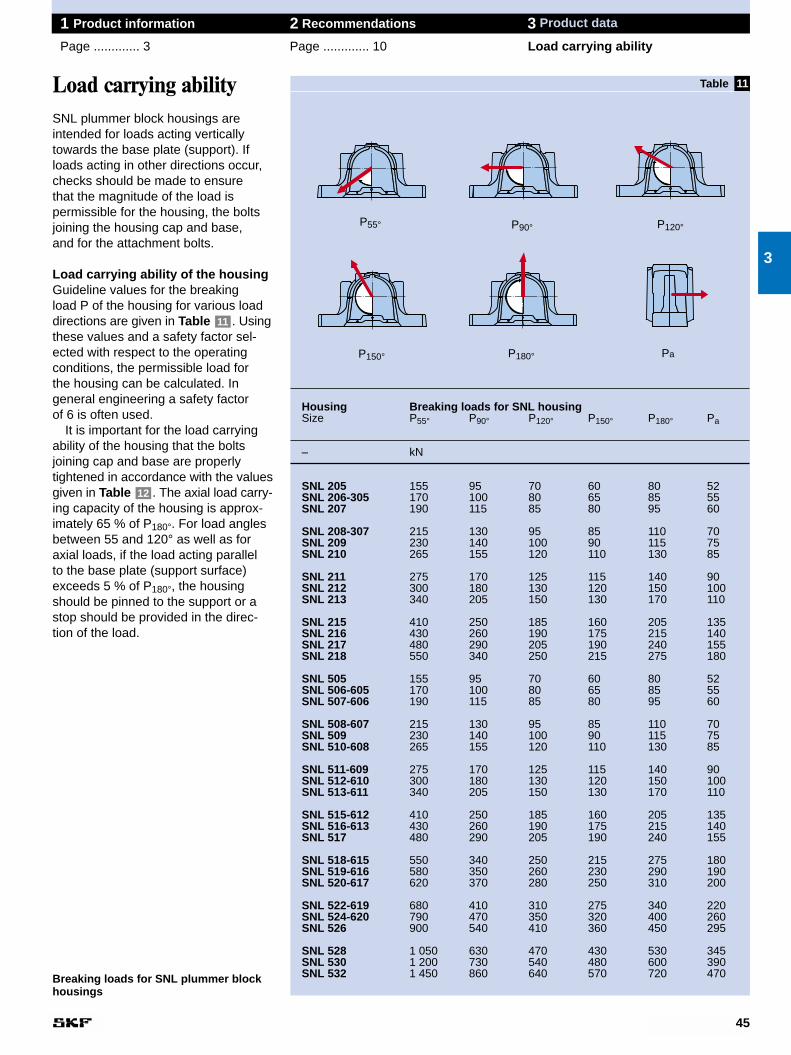
Housing Breaking loads for SNL housingSize P55° P90° P120° P150° P180° Pa
– kN
SNL 205 155 95 70 60 80 52SNL 206-305 170 100 80 65 85 55SNL 207 190 115 85 80 95 60
SNL 208-307 215 130 95 85 110 70SNL 209 230 140 100 90 115 75SNL 210 265 155 120 110 130 85
SNL 211 275 170 125 115 140 90SNL 212 300 180 130 120 150 100SNL 213 340 205 150 130 170 110
SNL 215 410 250 185 160 205 135SNL 216 430 260 190 175 215 140SNL 217 480 290 205 190 240 155SNL 218 550 340 250 215 275 180
SNL 505 155 95 70 60 80 52SNL 506-605 170 100 80 65 85 55SNL 507-606 190 115 85 80 95 60
SNL 508-607 215 130 95 85 110 70SNL 509 230 140 100 90 115 75SNL 510-608 265 155 120 110 130 85
SNL 511-609 275 170 125 115 140 90SNL 512-610 300 180 130 120 150 100SNL 513-611 340 205 150 130 170 110
SNL 515-612 410 250 185 160 205 135SNL 516-613 430 260 190 175 215 140SNL 517 480 290 205 190 240 155
SNL 518-615 550 340 250 215 275 180SNL 519-616 580 350 260 230 290 190SNL 520-617 620 370 280 250 310 200
SNL 522-619 680 410 310 275 340 220SNL 524-620 790 470 350 320 400 260SNL 526 900 540 410 360 450 295
SNL 528 1 050 630 470 430 530 345SNL 530 1 200 730 540 480 600 390SNL 532 1 450 860 640 570 720 470
11
45
1 Product information 2 Recommendations 3 Product data
Page ............. 3 Page ............. 10 Load carrying ability
Load carrying abilitySNL plummer block housings areintended for loads acting verticallytowards the base plate (support). Ifloads acting in other directions occur,checks should be made to ensure that the magnitude of the load is permissible for the housing, the boltsjoining the housing cap and base, and for the attachment bolts.
Load carrying ability of the housingGuideline values for the breaking load P of the housing for various loaddirections are given in Table . Usingthese values and a safety factor sel-ected with respect to the operatingconditions, the permissible load for the housing can be calculated. In general engineering a safety factor of 6 is often used.
It is important for the load carryingability of the housing that the bolts joining cap and base are properlytightened in accordance with the valuesgiven in Table . The axial load carry-ing capacity of the housing is approx-imately 65 % of P180°. For load anglesbetween 55 and 120° as well as foraxial loads, if the load acting parallel to the base plate (support surface)exceeds 5 % of P180°, the housingshould be pinned to the support or astop should be provided in the direc-tion of the load.
12
11
3
Breaking loads for SNL plummer blockhousings
P55° P90° P120°
P150° P180° Pa
Table
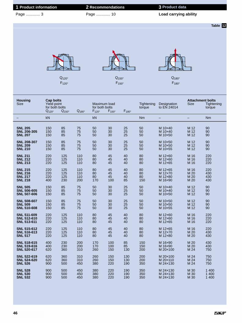
Housing Cap bolts Attachment boltsSize Yield point Maximum load Tightening Designation Size Tightening
for both bolts for both bolts torque to EN 24014 torqueQ120° Q150° Q180° F120° F150° F180°
– kN kN Nm – – Nm
SNL 205 150 85 75 50 30 25 50 M 10×40 M 12 90SNL 206-305 150 85 75 50 30 25 50 M 10×40 M 12 90SNL 207 150 85 75 50 30 25 50 M 10×50 M 12 90
SNL 208-307 150 85 75 50 30 25 50 M 10×50 M 12 90SNL 209 150 85 75 50 30 25 50 M 10×50 M 12 90SNL 210 150 85 75 50 30 25 50 M 10×55 M 12 90
SNL 211 220 125 110 80 45 40 80 M 12×60 M 16 220SNL 212 220 125 110 80 45 40 80 M 12×60 M 16 220SNL 213 220 125 110 80 45 40 80 M 12×65 M 16 220
SNL 215 220 125 110 80 45 40 80 M 12×65 M 16 220SNL 216 220 125 110 80 45 40 80 M 12×70 M 20 430SNL 217 220 125 110 80 45 40 80 M 12×80 M 20 430SNL 218 400 230 200 170 100 85 150 M 16×90 M 20 430
SNL 505 150 85 75 50 30 25 50 M 10×40 M 12 90SNL 506-605 150 85 75 50 30 25 50 M 10×40 M 12 90SNL 507-606 150 85 75 50 30 25 50 M 10×50 M 12 90
SNL 508-607 150 85 75 50 30 25 50 M 10×50 M 12 90SNL 509 150 85 75 50 30 25 50 M 10×50 M 12 90SNL 510-608 150 85 75 50 30 25 50 M 10×55 M 12 90
SNL 511-609 220 125 110 80 45 40 80 M 12×60 M 16 220SNL 512-610 220 125 110 80 45 40 80 M 12×60 M 16 220SNL 513-611 220 125 110 80 45 40 80 M 12×65 M 16 220
SNL 515-612 220 125 110 80 45 40 80 M 12×65 M 16 220SNL 516-613 220 125 110 80 45 40 80 M 12×70 M 20 430SNL 517 220 125 110 80 45 40 80 M 12×80 M 20 430
SNL 518-615 400 230 200 170 100 85 150 M 16×90 M 20 430SNL 519-616 400 230 200 170 100 85 150 M 16×90 M 20 430SNL 520-617 620 360 310 260 150 130 200 M 20×100 M 24 750
SNL 522-619 620 360 310 260 150 130 200 M 20×100 M 24 750SNL 524-620 620 360 310 260 150 130 200 M 20×110 M 24 750SNL 526 900 500 450 380 220 190 350 M 24×130 M 24 750
SNL 528 900 500 450 380 220 190 350 M 24×130 M 30 1 400SNL 530 900 500 450 380 220 190 350 M 24×130 M 30 1 400SNL 532 900 500 450 380 220 190 350 M 24×130 M 30 1 400
12
46
1 Product information 2 Recommendations 3 Product data
Page ............. 3 Page ............. 10 Load carrying ability
Table
Q120°F120°
Q150°F150°
Q180°F180°
47
1 Product information 2 Recommendations 3 Product data
Page ............. 3 Page ............. 10 Load carrying ability
Load carrying ability of boltsSNL plummer block housings are supplied with cap bolts (to join cap and base) to strength class 8.8 asstandard. The guideline values for theyield point Q for the cap bolts are givenin Table for various load directionsas well as the corresponding max-imum radial loads F.
12
3
Load carrying ability and tightening torques for cap bolts and attachmentbolts
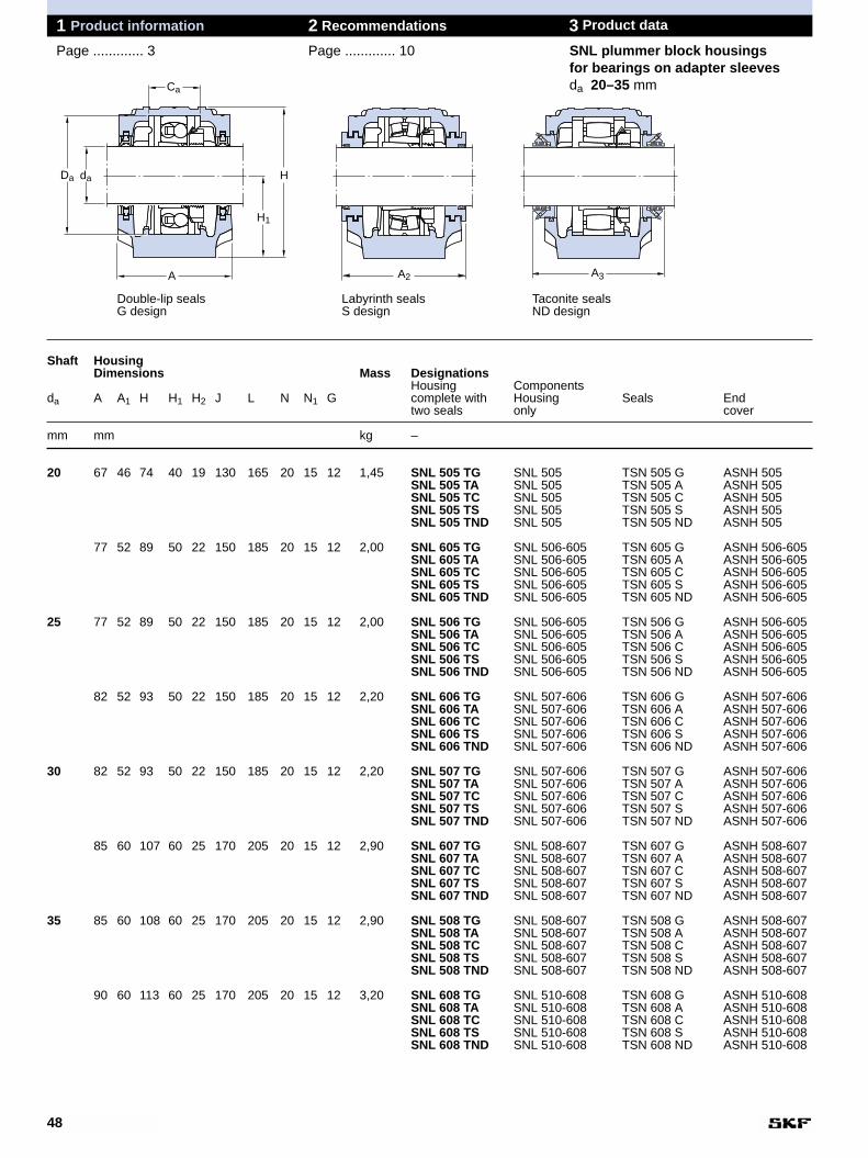
48
1 Product information 2 Recommendations 3 Product data
Page ............. 3 Page ............. 10 SNL plummer block housingsfor bearings on adapter sleevesda 20–35 mm
Shaft HousingDimensions Mass Designations
Housing Componentsda A A1 H H1 H2 J L N N1 G complete with Housing Seals End
two seals only cover
mm mm kg –
20 67 46 74 40 19 130 165 20 15 12 1,45 SNL 505 TG SNL 505 TSN 505 G ASNH 505SNL 505 TA SNL 505 TSN 505 A ASNH 505SNL 505 TC SNL 505 TSN 505 C ASNH 505SNL 505 TS SNL 505 TSN 505 S ASNH 505SNL 505 TND SNL 505 TSN 505 ND ASNH 505
77 52 89 50 22 150 185 20 15 12 2,00 SNL 605 TG SNL 506-605 TSN 605 G ASNH 506-605SNL 605 TA SNL 506-605 TSN 605 A ASNH 506-605SNL 605 TC SNL 506-605 TSN 605 C ASNH 506-605SNL 605 TS SNL 506-605 TSN 605 S ASNH 506-605SNL 605 TND SNL 506-605 TSN 605 ND ASNH 506-605
25 77 52 89 50 22 150 185 20 15 12 2,00 SNL 506 TG SNL 506-605 TSN 506 G ASNH 506-605SNL 506 TA SNL 506-605 TSN 506 A ASNH 506-605SNL 506 TC SNL 506-605 TSN 506 C ASNH 506-605SNL 506 TS SNL 506-605 TSN 506 S ASNH 506-605SNL 506 TND SNL 506-605 TSN 506 ND ASNH 506-605
82 52 93 50 22 150 185 20 15 12 2,20 SNL 606 TG SNL 507-606 TSN 606 G ASNH 507-606SNL 606 TA SNL 507-606 TSN 606 A ASNH 507-606SNL 606 TC SNL 507-606 TSN 606 C ASNH 507-606SNL 606 TS SNL 507-606 TSN 606 S ASNH 507-606SNL 606 TND SNL 507-606 TSN 606 ND ASNH 507-606
30 82 52 93 50 22 150 185 20 15 12 2,20 SNL 507 TG SNL 507-606 TSN 507 G ASNH 507-606SNL 507 TA SNL 507-606 TSN 507 A ASNH 507-606SNL 507 TC SNL 507-606 TSN 507 C ASNH 507-606SNL 507 TS SNL 507-606 TSN 507 S ASNH 507-606SNL 507 TND SNL 507-606 TSN 507 ND ASNH 507-606
85 60 107 60 25 170 205 20 15 12 2,90 SNL 607 TG SNL 508-607 TSN 607 G ASNH 508-607SNL 607 TA SNL 508-607 TSN 607 A ASNH 508-607SNL 607 TC SNL 508-607 TSN 607 C ASNH 508-607SNL 607 TS SNL 508-607 TSN 607 S ASNH 508-607SNL 607 TND SNL 508-607 TSN 607 ND ASNH 508-607
35 85 60 108 60 25 170 205 20 15 12 2,90 SNL 508 TG SNL 508-607 TSN 508 G ASNH 508-607SNL 508 TA SNL 508-607 TSN 508 A ASNH 508-607SNL 508 TC SNL 508-607 TSN 508 C ASNH 508-607SNL 508 TS SNL 508-607 TSN 508 S ASNH 508-607SNL 508 TND SNL 508-607 TSN 508 ND ASNH 508-607
90 60 113 60 25 170 205 20 15 12 3,20 SNL 608 TG SNL 510-608 TSN 608 G ASNH 510-608SNL 608 TA SNL 510-608 TSN 608 A ASNH 510-608SNL 608 TC SNL 510-608 TSN 608 C ASNH 510-608SNL 608 TS SNL 510-608 TSN 608 S ASNH 510-608SNL 608 TND SNL 510-608 TSN 608 ND ASNH 510-608
Double-lip seals Labyrinth seals Taconite sealsG design S design ND design
Ca
H
H1
A
daDa
A2 A3
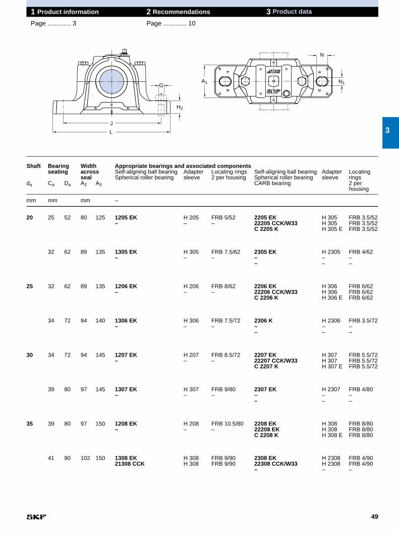
49
1 Product information 2 Recommendations 3 Product data
Page ............. 3 Page ............. 10
Shaft Bearing Width Appropriate bearings and associated componentsseating across Self-aligning ball bearing Adapter Locating rings Self-aligning ball bearing Adapter Locating
seal Spherical roller bearing sleeve 2 per housing Spherical roller bearing sleeve ringsda Ca Da A2 A3 CARB bearing 2 per
housing
mm mm mm –
20 25 52 80 125 1205 EK H 205 FRB 5/52 2205 EK H 305 FRB 3.5/52– – – 22205 CCK/W33 H 305 FRB 3.5/52
C 2205 K H 305 E FRB 3.5/52
32 62 89 135 1305 EK H 305 FRB 7.5/62 2305 EK H 2305 FRB 4/62– – – – – –
– – –
25 32 62 89 135 1206 EK H 206 FRB 8/62 2206 EK H 306 FRB 6/62– – – 22206 CCK/W33 H 306 FRB 6/62
C 2206 K H 306 E FRB 6/62
34 72 94 140 1306 EK H 306 FRB 7.5/72 2306 K H 2306 FRB 3.5/72– – – – – –
– – –
30 34 72 94 145 1207 EK H 207 FRB 8.5/72 2207 EK H 307 FRB 5.5/72– – – 22207 CCK/W33 H 307 FRB 5.5/72
C 2207 K H 307 E FRB 5.5/72
39 80 97 145 1307 EK H 307 FRB 9/80 2307 EK H 2307 FRB 4/80– – – – – –
– – –
35 39 80 97 150 1208 EK H 208 FRB 10.5/80 2208 EK H 308 FRB 8/80– – – 22208 EK H 308 FRB 8/80
C 2208 K H 308 E FRB 8/80
41 90 102 150 1308 EK H 308 FRB 9/90 2308 EK H 2308 FRB 4/9021308 CCK H 308 FRB 9/90 22308 CCK/W33 H 2308 FRB 4/90
– – –
3
H2
G
L
J
N
N1A1
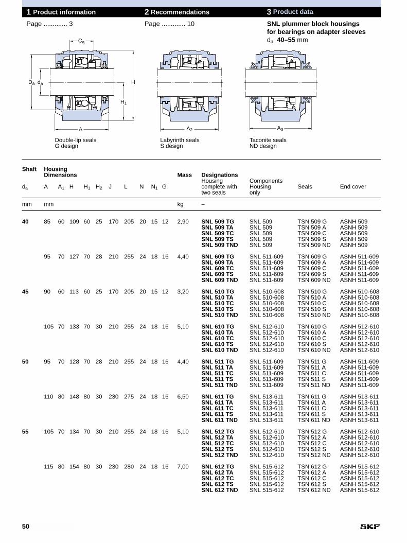
50
1 Product information 2 Recommendations 3 Product data
Page ............. 3 Page ............. 10 SNL plummer block housingsfor bearings on adapter sleevesda 40–55 mm
Shaft HousingDimensions Mass Designations
Housing Componentsda A A1 H H1 H2 J L N N1 G complete with Housing Seals End cover
two seals only
mm mm kg –
40 85 60 109 60 25 170 205 20 15 12 2,90 SNL 509 TG SNL 509 TSN 509 G ASNH 509SNL 509 TA SNL 509 TSN 509 A ASNH 509SNL 509 TC SNL 509 TSN 509 C ASNH 509SNL 509 TS SNL 509 TSN 509 S ASNH 509SNL 509 TND SNL 509 TSN 509 ND ASNH 509
95 70 127 70 28 210 255 24 18 16 4,40 SNL 609 TG SNL 511-609 TSN 609 G ASNH 511-609SNL 609 TA SNL 511-609 TSN 609 A ASNH 511-609SNL 609 TC SNL 511-609 TSN 609 C ASNH 511-609SNL 609 TS SNL 511-609 TSN 609 S ASNH 511-609SNL 609 TND SNL 511-609 TSN 609 ND ASNH 511-609
45 90 60 113 60 25 170 205 20 15 12 3,20 SNL 510 TG SNL 510-608 TSN 510 G ASNH 510-608SNL 510 TA SNL 510-608 TSN 510 A ASNH 510-608SNL 510 TC SNL 510-608 TSN 510 C ASNH 510-608SNL 510 TS SNL 510-608 TSN 510 S ASNH 510-608SNL 510 TND SNL 510-608 TSN 510 ND ASNH 510-608
105 70 133 70 30 210 255 24 18 16 5,10 SNL 610 TG SNL 512-610 TSN 610 G ASNH 512-610SNL 610 TA SNL 512-610 TSN 610 A ASNH 512-610SNL 610 TC SNL 512-610 TSN 610 C ASNH 512-610SNL 610 TS SNL 512-610 TSN 610 S ASNH 512-610SNL 610 TND SNL 512-610 TSN 610 ND ASNH 512-610
50 95 70 128 70 28 210 255 24 18 16 4,40 SNL 511 TG SNL 511-609 TSN 511 G ASNH 511-609SNL 511 TA SNL 511-609 TSN 511 A ASNH 511-609SNL 511 TC SNL 511-609 TSN 511 C ASNH 511-609SNL 511 TS SNL 511-609 TSN 511 S ASNH 511-609SNL 511 TND SNL 511-609 TSN 511 ND ASNH 511-609
110 80 148 80 30 230 275 24 18 16 6,50 SNL 611 TG SNL 513-611 TSN 611 G ASNH 513-611SNL 611 TA SNL 513-611 TSN 611 A ASNH 513-611SNL 611 TC SNL 513-611 TSN 611 C ASNH 513-611SNL 611 TS SNL 513-611 TSN 611 S ASNH 513-611SNL 611 TND SNL 513-611 TSN 611 ND ASNH 513-611
55 105 70 134 70 30 210 255 24 18 16 5,10 SNL 512 TG SNL 512-610 TSN 512 G ASNH 512-610SNL 512 TA SNL 512-610 TSN 512 A ASNH 512-610SNL 512 TC SNL 512-610 TSN 512 C ASNH 512-610SNL 512 TS SNL 512-610 TSN 512 S ASNH 512-610SNL 512 TND SNL 512-610 TSN 512 ND ASNH 512-610
115 80 154 80 30 230 280 24 18 16 7,00 SNL 612 TG SNL 515-612 TSN 612 G ASNH 515-612SNL 612 TA SNL 515-612 TSN 612 A ASNH 515-612SNL 612 TC SNL 515-612 TSN 612 C ASNH 515-612SNL 612 TS SNL 515-612 TSN 612 S ASNH 515-612SNL 612 TND SNL 515-612 TSN 612 ND ASNH 515-612
Double-lip seals Labyrinth seals Taconite sealsG design S design ND design
A2
Ca
H
H1
A
daDa
A3

51
1 Product information 2 Recommendations 3 Product data
Page ............. 3 Page ............. 10
Shaft Bearing Width Appropriate bearings and associated componentsseating across Self-aligning ball bearing Adapter Locating rings Self-aligning ball bearing Adapter Locating
seal Spherical roller bearing sleeve 2 per housing Spherical roller bearing sleeve ringsda Ca Da A2 A3 CARB bearing 2 per
housing
mm mm mm –
40 30 85 97 150 1209 EK H 209 FRB 5.5/85 2209 EK H 309 FRB 3.5/85– – – 22209 CCK/W33 H 309 FRB 3.5/85
C 2209 K H 309 E FRB 3.5/85
44 100 107 155 1309 EK H 309 FRB 9.5/100 2309 EK H 2309 FRB 4/10021309 EK H 309 FRB 9.5/100 22309 CCK/W33 H 2309 FRB 4/100
– – –
45 41 90 102 155 1210 EK H 210 FRB 10.5/90 2210 EK H 310 FRB 9/90– – – 22210 CCK/W33 H 310 FRB 9/90
C 2210 K H 310 E FRB 9/90
48 110 117 165 1310 EK H 310 FRB 10.5/110 2310 K H 2310 FRB 4/11021310 EK H 310 FRB 10.5/110 22310 CCK/W33 H 2310 FRB 4/110
– – –
50 44 100 107 165 1211 EK H 211 FRB 11.5/100 2211 EK H 311 FRB 9.5/100– – – 22211 EK H 311 FRB 9.5/100
C 2211 K H 311 E FRB 9.5/100
51 120 122 170 1311 EK H 311 FRB 11/120 2311 K H 2311 FRB 4/12021311 EK H 311 FRB 11/120 22311 EK H 2311 FRB 4/120
– – –
55 48 110 117 175 1212 EK H 212 FRB 13/110 2212 EK H 312 FRB 10/110– – – 22212 EK H 312 FRB 10/110
C 2212 K H 312 E FRB 10/110
56 130 127 175 1312 EK H 312 FRB 12.5/130 2312 K H 2312 FRB 5/13021312 EK H 312 FRB 12.5/130 22312 EK H 2312 FRB 5/130
– – –
3
H2
G
L
J
N
N1A1

52
1 Product information 2 Recommendations 3 Product data
Page ............. 3 Page ............. 10 SNL plummer block housingsfor bearings on adapter sleevesda 60–75 mm
Shaft HousingDimensions Mass Designations
Housing Componentsda A A1 H H1 H2 J L N N1 G complete with Housing Seals End cover
two seals only
mm mm kg –
60 110 80 149 80 30 230 275 24 18 16 6,50 SNL 513 TG SNL 513-611 TSN 513 G ASNH 513-611SNL 513 TA SNL 513-611 TSN 513 A ASNH 513-611SNL 513 TC SNL 513-611 TSN 513 C ASNH 513-611SNL 513 TS SNL 513-611 TSN 513 S ASNH 513-611SNL 513 TND SNL 513-611 TSN 513 ND ASNH 513-611
120 90 175 95 32 260 315 28 22 20 9,50 SNL 613 TG SNL 516-613 TSN 613 G ASNH 516-613SNL 613 TA SNL 516-613 TSN 613 A ASNH 516-613SNL 613 TC SNL 516-613 TSN 613 C ASNH 516-613SNL 613 TS SNL 516-613 TSN 613 S ASNH 516-613SNL 613 TND SNL 516-613 TSN 613 ND ASNH 516-613
65 115 80 155 80 30 230 280 24 18 16 7,00 SNL 515 TG SNL 515-612 TSN 515 G ASNH 515-612SNL 515 TA SNL 515-612 TSN 515 A ASNH 515-612SNL 515 TC SNL 515-612 TSN 515 C ASNH 515-612SNL 515 TS SNL 515-612 TSN 515 S ASNH 515-612SNL 515 TND SNL 515-612 TSN 515 ND ASNH 515-612
140 100 193 100 35 290 345 28 22 20 12,5 SNL 615 TG SNL 518-615 TSN 615 G ASNH 518-615SNL 615 TA SNL 518-615 TSN 615 A ASNH 518-615SNL 615 TC SNL 518-615 TSN 615 C ASNH 518-615SNL 615 TS SNL 518-615 TSN 615 S ASNH 518-615SNL 615 TND SNL 518-615 TSN 615 ND ASNH 518-615
70 120 90 177 95 32 260 315 28 22 20 9,50 SNL 516 TG SNL 516-613 TSN 516 G ASNH 516-613SNL 516 TA SNL 516-613 TSN 516 A ASNH 516-613SNL 516 TC SNL 516-613 TSN 516 C ASNH 516-613SNL 516 TS SNL 516-613 TSN 516 S ASNH 516-613SNL 516 TND SNL 516-613 TSN 516 ND ASNH 516-613
145 100 210 112 35 290 345 28 22 20 13,7 SNL 616 TG SNL 519-616 TSN 616 G ASNH 519-616SNL 616 TA SNL 519-616 TSN 616 A ASNH 519-616SNL 616 TC SNL 519-616 TSN 616 C ASNH 519-616SNL 616 TS SNL 519-616 TSN 616 S ASNH 519-616SNL 616 TND SNL 519-616 TSN 616 ND ASNH 519-616
75 125 90 183 95 32 260 320 28 22 20 10,0 SNL 517 TG SNL 517 TSN 517 G ASNH 517SNL 517 TA SNL 517 TSN 517 A ASNH 517SNL 517 TC SNL 517 TSN 517 C ASNH 517SNL 517 TS SNL 517 TSN 517 S ASNH 517SNL 517 TND SNL 517 TSN 517 ND ASNH 517
160 110 215 112 40 320 380 32 26 24 17,6 SNL 617 TG SNL 520-617 TSN 617 G ASNH 520-617SNL 617 TA SNL 520-617 TSN 617 A ASNH 520-617SNL 617 TC SNL 520-617 TSN 617 C ASNH 520-617SNL 617 TS SNL 520-617 TSN 617 S ASNH 520-617SNL 617 TND SNL 520-617 TSN 617 ND ASNH 520-617
Double-lip seals Labyrinth seals Taconite sealsG design S design ND design
A2
Ca
H
H1
A
daDa
A3
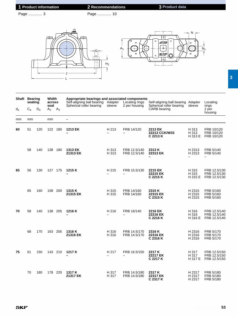
53
1 Product information 2 Recommendations 3 Product data
Page ............. 3 Page ............. 10
Shaft Bearing Width Appropriate bearings and associated componentsseating across Self-aligning ball bearing Adapter Locating rings Self-aligning ball bearing Adapter Locating
seal Spherical roller bearing sleeve 2 per housing Spherical roller bearing sleeve ringsda Ca Da A2 A3 CARB bearing 2 per
housing
mm mm mm –
60 51 120 122 180 1213 EK H 213 FRB 14/120 2213 EK H 313 FRB 10/120– – – 22213 CCK/W33 H 313 FRB 10/120
C 2213 K H 313 E FRB 10/120
58 140 138 180 1313 EK H 313 FRB 12.5/140 2313 K H 2313 FRB 5/14021313 EK H 313 FRB 12.5/140 22313 EK H 2313 FRB 5/140
– – –
65 56 130 127 175 1215 K H 215 FRB 15.5/130 2215 EK H 315 FRB 12.5/130– – – 22215 EK H 315 FRB 12.5/130
C 2215 K H 315 E FRB 12.5/130
65 160 158 200 1315 K H 315 FRB 14/160 2315 K H 2315 FRB 5/16021315 EK H 315 FRB 14/160 22315 EK H 2315 FRB 5/160
C 2315 K H 2315 FRB 5/160
70 58 140 138 205 1216 K H 216 FRB 16/140 2216 EK H 316 FRB 12.5/140– – – 22216 EK H 316 FRB 12.5/140
C 2216 K H 316 E FRB 12.5/140
68 170 163 205 1316 K H 316 FRB 14.5/170 2316 K H 2316 FRB 5/17021316 EK H 316 FRB 14.5/170 22316 EK H 2316 FRB 5/170
C 2316 K H 2316 FRB 5/170
75 61 150 143 210 1217 K H 217 FRB 16.5/150 2217 K H 317 FRB 12.5/150– – – 22217 EK H 317 FRB 12.5/150
C 2217 K H 317 E FRB 12.5/150
70 180 178 220 1317 K H 317 FRB 14.5/180 2317 K H 2317 FRB 5/18021317 EK H 317 FRB 14.5/180 22317 EK H 2317 FRB 5/180
C 2317 K H 2317 FRB 5/180
3
H2
G
L
J
N
N1A1

54
1 Product information 2 Recommendations 3 Product data
Page ............. 3 Page ............. 10 SNL plummer block housingsfor bearings on adapter sleevesda 80–115 mm
Shaft HousingDimensions Mass Designations
Housing Componentsda A A1 H H1 H2 J L N N1 G complete with Housing Seals End cover
two seals only
mm mm kg –
80 140 100 194 100 35 290 345 28 22 20 12,5 SNL 518 TG SNL 518-615 TSN 518 G ASNH 518-615SNL 518 TA SNL 518-615 TSN 518 A ASNH 518-615SNL 518 TC SNL 518-615 TSN 518 C ASNH 518-615SNL 518 TS SNL 518-615 TSN 518 S ASNH 518-615SNL 518 TND SNL 518-615 TSN 518 ND ASNH 518-615
85 145 100 212 112 35 290 345 28 22 20 13,7 SNL 519 TG SNL 519-616 TSN 519 G ASNH 519-616SNL 519 TA SNL 519-616 TSN 519 A ASNH 519-616SNL 519 TC SNL 519-616 TSN 519 C ASNH 519-616SNL 519 TS SNL 519-616 TSN 519 S ASNH 519-616SNL 519 TND SNL 519-616 TSN 519 ND ASNH 519-616
175 120 239 125 45 350 410 32 26 24 22,0 SNL 619 TG SNL 522-619 TSN 619 G ASNH 522-619SNL 619 TS SNL 522-619 TSN 619 A ASNH 522-619SNL 619 TC SNL 522-619 TSN 619 C ASNH 522-619SNL 619 TS SNL 522-619 TSN 619 S ASNH 522-619SNL 619 TND SNL 522-619 TSN 619 ND ASNH 522-619
90 160 110 218 112 40 320 380 32 26 24 17,6 SNL 520 TG SNL 520-617 TSN 520 G ASNH 520-617SNL 520 TA SNL 520-617 TSN 520 A ASNH 520-617SNL 520 TC SNL 520-617 TSN 520 C ASNH 520-617SNL 520 TS SNL 520-617 TSN 520 S ASNH 520-617SNL 520 TND SNL 520-617 TSN 520 ND ASNH 520-617
185 120 271 140 45 350 410 32 26 24 26,2 SNL 620 TG SNL 524-620 TSN 620 G ASNH 524-620SNL 620 TA SNL 524-620 TSN 620 A ASNH 524-620SNL 620 TC SNL 524-620 TSN 620 C ASNH 524-620SNL 620 TS SNL 524-620 TSN 620 S ASNH 524-620SNL 620 TND SNL 524-620 TSN 620 ND ASNH 524-620
100 175 120 242 125 45 350 410 32 26 24 22,0 SNL 522 TG SNL 522-619 TSN 522 G ASNH 522-619SNL 522 TA SNL 522-619 TSN 522 A ASNH 522-619SNL 522 TC SNL 522-619 TSN 522 C ASNH 522-619SNL 522 TS SNL 522-619 TSN 522 S ASNH 522-619SNL 522 TND SNL 522-619 TSN 522 ND ASNH 522-619
110 185 120 271 140 45 350 410 32 26 24 26,2 SNL 524 TG SNL 524-620 TSN 524 G ASNH 524-620SNL 524 TA SNL 524-620 TSN 524 A ASNH 524-620SNL 524 TC SNL 524-620 TSN 524 C ASNH 524-620SNL 524 TS SNL 524-620 TSN 524 S ASNH 524-620SNL 524 TND SNL 524-620 TSN 524 ND ASNH 524-620
115 190 130 290 150 50 380 445 35 28 24 33,0 SNL 526 TG SNL 526 TSN 526 G ASNH 526SNL 526 TA SNL 526 TSN 526 A ASNH 526SNL 526 TC SNL 526 TSN 526 C ASNH 526SNL 526 TS SNL 526 TSN 526 S ASNH 526SNL 526 TND SNL 526 TSN 526 ND ASNH 526
Double-lip seals Labyrinth seals Taconite sealsG design S design ND design
A2
Ca
H
H1
A
daDa
A3
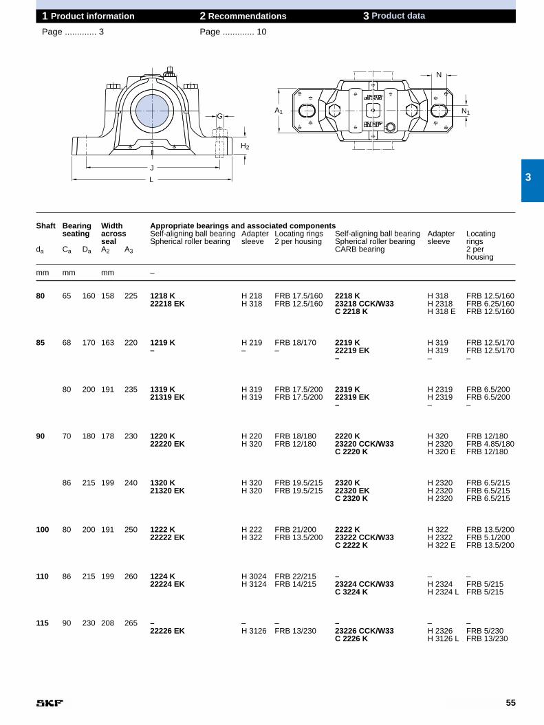
55
1 Product information 2 Recommendations 3 Product data
Page ............. 3 Page ............. 10
Shaft Bearing Width Appropriate bearings and associated componentsseating across Self-aligning ball bearing Adapter Locating rings Self-aligning ball bearing Adapter Locating
seal Spherical roller bearing sleeve 2 per housing Spherical roller bearing sleeve ringsda Ca Da A2 A3 CARB bearing 2 per
housing
mm mm mm –
80 65 160 158 225 1218 K H 218 FRB 17.5/160 2218 K H 318 FRB 12.5/16022218 EK H 318 FRB 12.5/160 23218 CCK/W33 H 2318 FRB 6.25/160
C 2218 K H 318 E FRB 12.5/160
85 68 170 163 220 1219 K H 219 FRB 18/170 2219 K H 319 FRB 12.5/170– – – 22219 EK H 319 FRB 12.5/170
– – –
80 200 191 235 1319 K H 319 FRB 17.5/200 2319 K H 2319 FRB 6.5/20021319 EK H 319 FRB 17.5/200 22319 EK H 2319 FRB 6.5/200
– – –
90 70 180 178 230 1220 K H 220 FRB 18/180 2220 K H 320 FRB 12/18022220 EK H 320 FRB 12/180 23220 CCK/W33 H 2320 FRB 4.85/180
C 2220 K H 320 E FRB 12/180
86 215 199 240 1320 K H 320 FRB 19.5/215 2320 K H 2320 FRB 6.5/21521320 EK H 320 FRB 19.5/215 22320 EK H 2320 FRB 6.5/215
C 2320 K H 2320 FRB 6.5/215
100 80 200 191 250 1222 K H 222 FRB 21/200 2222 K H 322 FRB 13.5/20022222 EK H 322 FRB 13.5/200 23222 CCK/W33 H 2322 FRB 5.1/200
C 2222 K H 322 E FRB 13.5/200
110 86 215 199 260 1224 K H 3024 FRB 22/215 – – –22224 EK H 3124 FRB 14/215 23224 CCK/W33 H 2324 FRB 5/215
C 3224 K H 2324 L FRB 5/215
115 90 230 208 265 – – – – – –22226 EK H 3126 FRB 13/230 23226 CCK/W33 H 2326 FRB 5/230
C 2226 K H 3126 L FRB 13/230
3
H2
G
L
J
N
N1A1
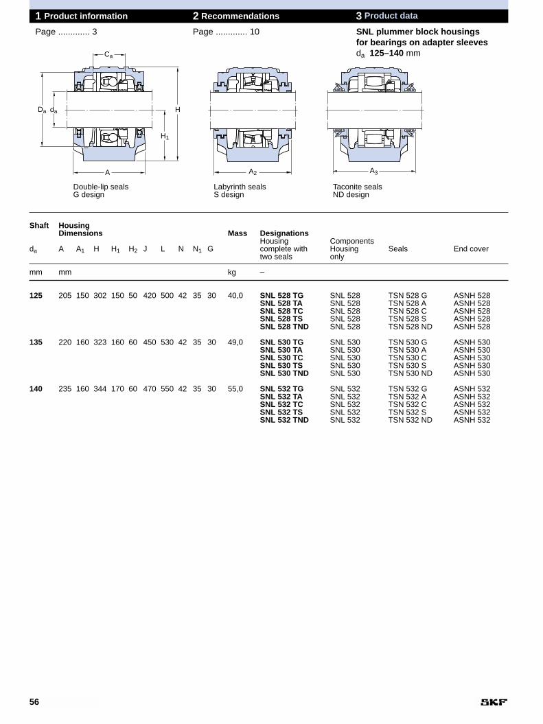
56
1 Product information 2 Recommendations 3 Product data
Page ............. 3 Page ............. 10 SNL plummer block housingsfor bearings on adapter sleevesda 125–140 mm
Shaft HousingDimensions Mass Designations
Housing Componentsda A A1 H H1 H2 J L N N1 G complete with Housing Seals End cover
two seals only
mm mm kg –
125 205 150 302 150 50 420 500 42 35 30 40,0 SNL 528 TG SNL 528 TSN 528 G ASNH 528SNL 528 TA SNL 528 TSN 528 A ASNH 528SNL 528 TC SNL 528 TSN 528 C ASNH 528SNL 528 TS SNL 528 TSN 528 S ASNH 528SNL 528 TND SNL 528 TSN 528 ND ASNH 528
135 220 160 323 160 60 450 530 42 35 30 49,0 SNL 530 TG SNL 530 TSN 530 G ASNH 530SNL 530 TA SNL 530 TSN 530 A ASNH 530SNL 530 TC SNL 530 TSN 530 C ASNH 530SNL 530 TS SNL 530 TSN 530 S ASNH 530SNL 530 TND SNL 530 TSN 530 ND ASNH 530
140 235 160 344 170 60 470 550 42 35 30 55,0 SNL 532 TG SNL 532 TSN 532 G ASNH 532SNL 532 TA SNL 532 TSN 532 A ASNH 532SNL 532 TC SNL 532 TSN 532 C ASNH 532SNL 532 TS SNL 532 TSN 532 S ASNH 532SNL 532 TND SNL 532 TSN 532 ND ASNH 532
Double-lip seals Labyrinth seals Taconite sealsG design S design ND design
A2
Ca
H
H1
A
daDa
A3
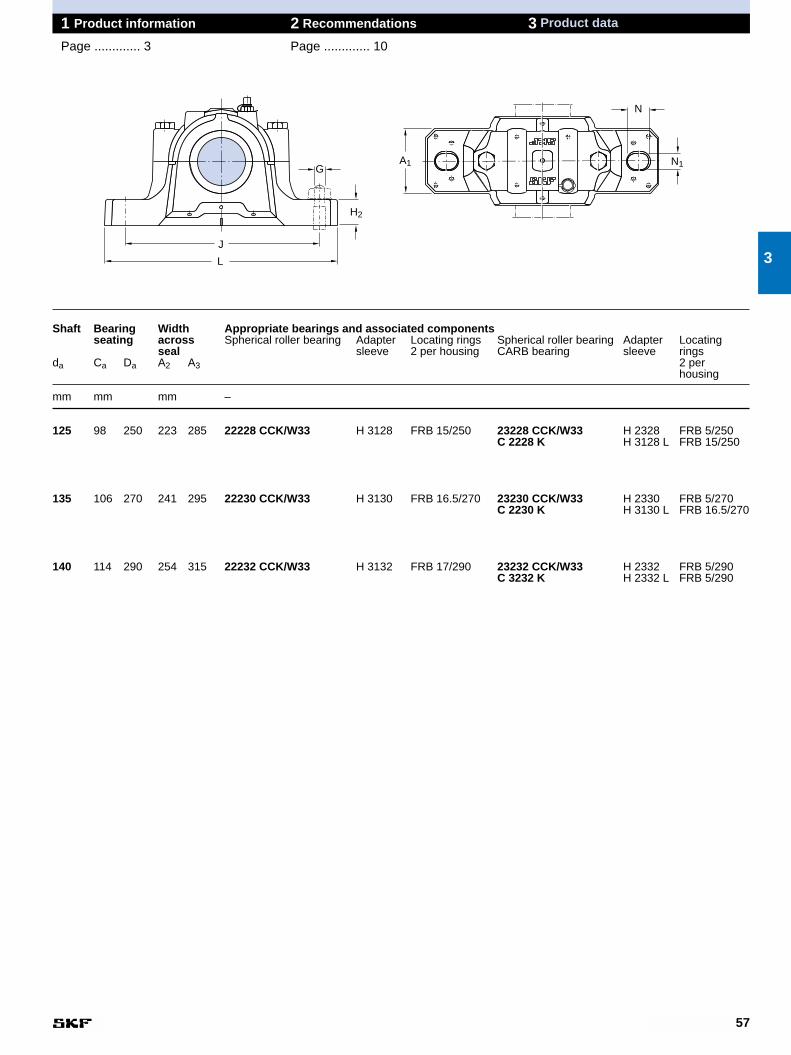
57
1 Product information 2 Recommendations 3 Product data
Page ............. 3 Page ............. 10
Shaft Bearing Width Appropriate bearings and associated componentsseating across Spherical roller bearing Adapter Locating rings Spherical roller bearing Adapter Locating
seal sleeve 2 per housing CARB bearing sleeve ringsda Ca Da A2 A3 2 per
housing
mm mm mm –
125 98 250 223 285 22228 CCK/W33 H 3128 FRB 15/250 23228 CCK/W33 H 2328 FRB 5/250C 2228 K H 3128 L FRB 15/250
135 106 270 241 295 22230 CCK/W33 H 3130 FRB 16.5/270 23230 CCK/W33 H 2330 FRB 5/270C 2230 K H 3130 L FRB 16.5/270
140 114 290 254 315 22232 CCK/W33 H 3132 FRB 17/290 23232 CCK/W33 H 2332 FRB 5/290C 3232 K H 2332 L FRB 5/290
3
H2
G
L
J
N
N1A1
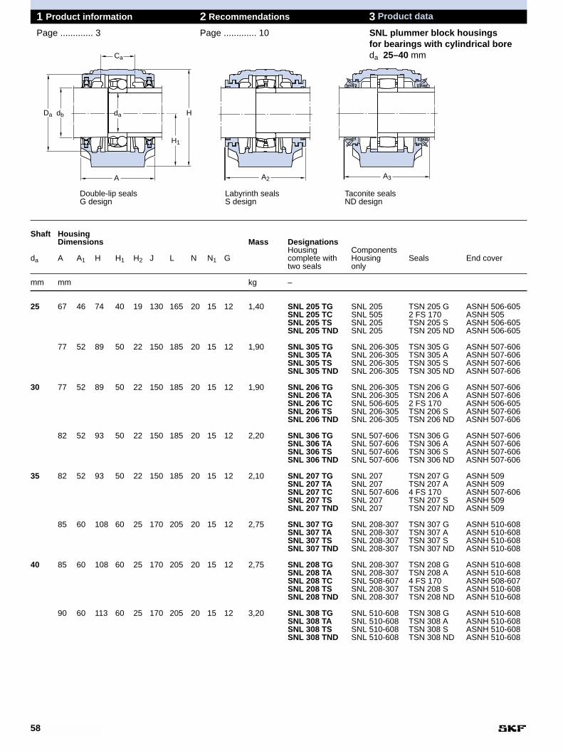
58
Shaft HousingDimensions Mass Designations
Housing Componentsda A A1 H H1 H2 J L N N1 G complete with Housing Seals End cover
two seals only
mm mm kg –
25 67 46 74 40 19 130 165 20 15 12 1,40 SNL 205 TG SNL 205 TSN 205 G ASNH 506-605SNL 205 TC SNL 505 2 FS 170 ASNH 505SNL 205 TS SNL 205 TSN 205 S ASNH 506-605SNL 205 TND SNL 205 TSN 205 ND ASNH 506-605
77 52 89 50 22 150 185 20 15 12 1,90 SNL 305 TG SNL 206-305 TSN 305 G ASNH 507-606SNL 305 TA SNL 206-305 TSN 305 A ASNH 507-606SNL 305 TS SNL 206-305 TSN 305 S ASNH 507-606SNL 305 TND SNL 206-305 TSN 305 ND ASNH 507-606
30 77 52 89 50 22 150 185 20 15 12 1,90 SNL 206 TG SNL 206-305 TSN 206 G ASNH 507-606SNL 206 TA SNL 206-305 TSN 206 A ASNH 507-606SNL 206 TC SNL 506-605 2 FS 170 ASNH 506-605SNL 206 TS SNL 206-305 TSN 206 S ASNH 507-606SNL 206 TND SNL 206-305 TSN 206 ND ASNH 507-606
82 52 93 50 22 150 185 20 15 12 2,20 SNL 306 TG SNL 507-606 TSN 306 G ASNH 507-606SNL 306 TA SNL 507-606 TSN 306 A ASNH 507-606SNL 306 TS SNL 507-606 TSN 306 S ASNH 507-606SNL 306 TND SNL 507-606 TSN 306 ND ASNH 507-606
35 82 52 93 50 22 150 185 20 15 12 2,10 SNL 207 TG SNL 207 TSN 207 G ASNH 509SNL 207 TA SNL 207 TSN 207 A ASNH 509SNL 207 TC SNL 507-606 4 FS 170 ASNH 507-606SNL 207 TS SNL 207 TSN 207 S ASNH 509SNL 207 TND SNL 207 TSN 207 ND ASNH 509
85 60 108 60 25 170 205 20 15 12 2,75 SNL 307 TG SNL 208-307 TSN 307 G ASNH 510-608SNL 307 TA SNL 208-307 TSN 307 A ASNH 510-608SNL 307 TS SNL 208-307 TSN 307 S ASNH 510-608SNL 307 TND SNL 208-307 TSN 307 ND ASNH 510-608
40 85 60 108 60 25 170 205 20 15 12 2,75 SNL 208 TG SNL 208-307 TSN 208 G ASNH 510-608SNL 208 TA SNL 208-307 TSN 208 A ASNH 510-608SNL 208 TC SNL 508-607 4 FS 170 ASNH 508-607SNL 208 TS SNL 208-307 TSN 208 S ASNH 510-608SNL 208 TND SNL 208-307 TSN 208 ND ASNH 510-608
90 60 113 60 25 170 205 20 15 12 3,20 SNL 308 TG SNL 510-608 TSN 308 G ASNH 510-608SNL 308 TA SNL 510-608 TSN 308 A ASNH 510-608SNL 308 TS SNL 510-608 TSN 308 S ASNH 510-608SNL 308 TND SNL 510-608 TSN 308 ND ASNH 510-608
1 Product information 2 Recommendations 3 Product data
Page ............. 3 Page ............. 10 SNL plummer block housingsfor bearings with cylindrical boreda 25–40 mm
Double-lip seals Labyrinth seals Taconite sealsG design S design ND design
Ca
dadbDa
A
H
H1
A2 A3
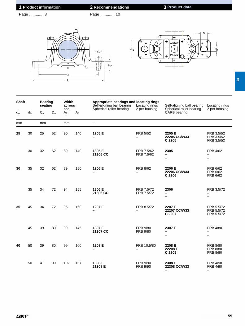
59
1 Product information 2 Recommendations 3 Product data
Page ............. 3 Page ............. 10
Shaft Bearing Width Appropriate bearings and locating ringsseating across Self-aligning ball bearing Locating rings Self-aligning ball bearing Locating rings
seal Spherical roller bearing 2 per housing Spherical roller bearing 2 per housingda db Ca Da A2 A3 CARB bearing
mm mm mm –
25 30 25 52 90 140 1205 E FRB 5/52 2205 E FRB 3.5/52– – 22205 CC/W33 FRB 3.5/52
C 2205 FRB 3.5/52
30 32 62 89 140 1305 E FRB 7.5/62 2305 FRB 4/6221305 CC FRB 7.5/62 – –
– –
30 35 32 62 89 150 1206 E FRB 8/62 2206 E FRB 6/62– – 22206 CC/W33 FRB 6/62
C 2206 FRB 6/62
35 34 72 94 155 1306 E FRB 7.5/72 2306 FRB 3.5/7221306 CC FRB 7.5/72 – –
– –
35 45 34 72 96 160 1207 E FRB 8.5/72 2207 E FRB 5.5/72– – 22207 CC/W33 FRB 5.5/72
C 2207 FRB 5.5/72
45 39 80 99 145 1307 E FRB 9/80 2307 E FRB 4/8021307 CC FRB 9/80 – –
– –
40 50 39 80 99 160 1208 E FRB 10.5/80 2208 E FRB 8/80– – 22208 E FRB 8/80
C 2208 FRB 8/80
50 41 90 102 167 1308 E FRB 9/90 2308 E FRB 4/9021308 E FRB 9/90 22308 CC/W33 FRB 4/90
– –
3
G
H2
L
J
N1A1
N

60
1 Product information 2 Recommendations 3 Product data
Page ............. 3 Page ............. 10 SNL plummer block housingsfor bearings with cylindrical boreda 45–60 mm
Shaft HousingDimensions Mass Designations
Housing Componentsda A A1 H H1 H2 J L N N1 G complete with Housing Seals End cover
two seals only
mm mm kg –
45 85 60 109 60 25 170 205 20 15 12 2,75 SNL 209 TG SNL 209 TSN 209 G ASNH 511-609SNL 209 TA SNL 209 TSN 209 A ASNH 511-609SNL 209 TC SNL 509 4 FS 170 ASNH 509SNL 209 TS SNL 209 TSN 209 S ASNH 511-609SNL 209 TND SNL 209 TSN 209 ND ASNH 511-609
95 70 128 70 28 210 255 24 18 16 4,40 SNL 309 TG SNL 511-609 TSN 309 G ASNH 511-609SNL 309 TA SNL 511-609 TSN 309 A ASNH 511-609SNL 309 TS SNL 511-609 TSN 309 S ASNH 511-609SNL 309 TND SNL 511-609 TSN 309 ND ASNH 511-609
50 90 60 113 60 25 170 205 20 15 12 3,00 SNL 210 TG SNL 210 TSN 210 G ASNH 512-610SNL 210 TA SNL 210 TSN 210 A ASNH 512-610SNL 210 TC SNL 510-608 4 FS 170 ASNH 510-608SNL 210 TS SNL 210 TSN 210 S ASNH 512-610SNL 210 TND SNL 210 TSN 210 ND ASNH 512-610
105 70 134 70 30 210 255 24 18 16 5,10 SNL 310 TG SNL 512-610 TSN 310 G ASNH 512-610SNL 310 TA SNL 512-610 TSN 310 A ASNH 512-610SNL 310 TS SNL 512-610 TSN 310 S ASNH 512-610SNL 310 TND SNL 512-610 TSN 310 ND ASNH 512-610
55 95 70 128 70 28 210 255 24 18 16 4,20 SNL 211 TG SNL 211 TSN 211 G ASNH 513-611SNL 211 TA SNL 211 TSN 211 A ASNH 513-611SNL 211 TC SNL 511-609 4 FS 170 ASNH 511-609SNL 211 TS SNL 211 TSN 211 S ASNH 513-611SNL 211 TND SNL 211 TSN 211 ND ASNH 513-611
110 80 149 80 30 230 275 24 18 16 6,50 SNL 311 TG SNL 513-611 TSN 311 G ASNH 513-611SNL 311 TA SNL 513-611 TSN 311 A ASNH 513-611SNL 311 TS SNL 513-611 TSN 311 S ASNH 513-611SNL 311 TND SNL 513-611 TSN 311 ND ASNH 513-611
60 105 70 134 70 30 210 255 24 18 16 4,75 SNL 212 TG SNL 212 TSN 212 G ASNH 515-612SNL 212 TA SNL 212 TSN 212 A ASNH 515-612SNL 212 TC SNL 512-610 4 FS 170 ASNH 512-610SNL 212 TS SNL 212 TSN 212 S ASNH 515-612SNL 212 TND SNL 212 TSN 212 ND ASNH 515-612
115 80 155 80 30 230 280 24 18 16 7,00 SNL 312 TG SNL 515-612 TSN 312 G ASNH 515-612SNL 312 TA SNL 515-612 TSN 312 A ASNH 515-612SNL 312 TS SNL 515-612 TSN 312 S ASNH 515-612SNL 312 TND SNL 515-612 TSN 312 ND ASNH 515-612
Double-lip seals Labyrinth seals Taconite sealsG design S design ND design
Ca
dadbDa
A
H
H1
A2 A3
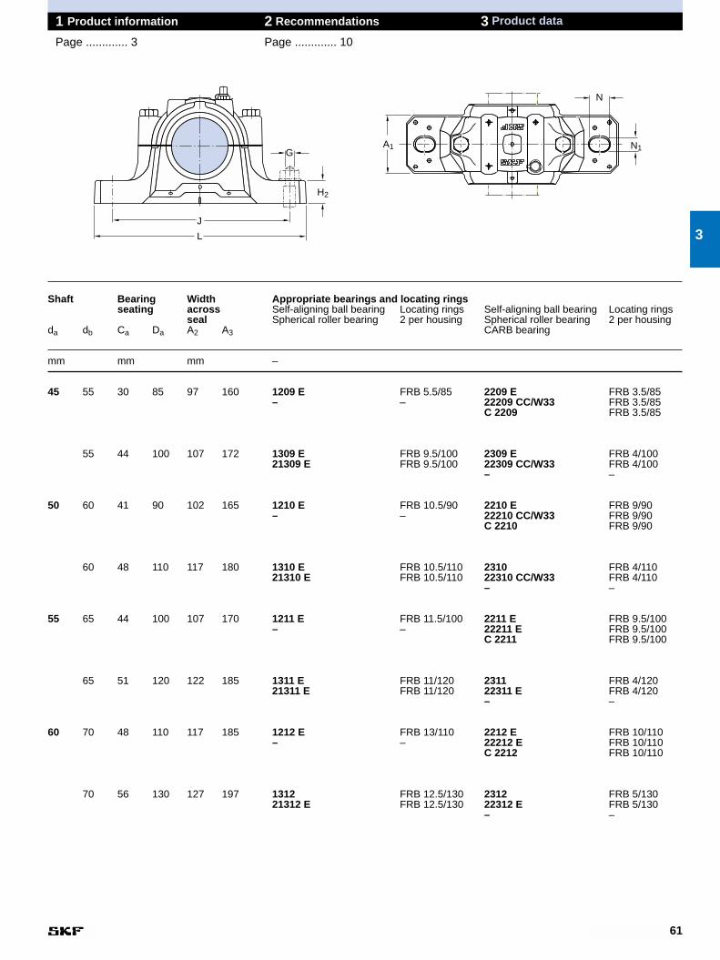
61
1 Product information 2 Recommendations 3 Product data
Page ............. 3 Page ............. 10
Shaft Bearing Width Appropriate bearings and locating ringsseating across Self-aligning ball bearing Locating rings Self-aligning ball bearing Locating rings
seal Spherical roller bearing 2 per housing Spherical roller bearing 2 per housingda db Ca Da A2 A3 CARB bearing
mm mm mm –
45 55 30 85 97 160 1209 E FRB 5.5/85 2209 E FRB 3.5/85– – 22209 CC/W33 FRB 3.5/85
C 2209 FRB 3.5/85
55 44 100 107 172 1309 E FRB 9.5/100 2309 E FRB 4/10021309 E FRB 9.5/100 22309 CC/W33 FRB 4/100
– –
50 60 41 90 102 165 1210 E FRB 10.5/90 2210 E FRB 9/90– – 22210 CC/W33 FRB 9/90
C 2210 FRB 9/90
60 48 110 117 180 1310 E FRB 10.5/110 2310 FRB 4/11021310 E FRB 10.5/110 22310 CC/W33 FRB 4/110
– –
55 65 44 100 107 170 1211 E FRB 11.5/100 2211 E FRB 9.5/100– – 22211 E FRB 9.5/100
C 2211 FRB 9.5/100
65 51 120 122 185 1311 E FRB 11/120 2311 FRB 4/12021311 E FRB 11/120 22311 E FRB 4/120
– –
60 70 48 110 117 185 1212 E FRB 13/110 2212 E FRB 10/110– – 22212 E FRB 10/110
C 2212 FRB 10/110
70 56 130 127 197 1312 FRB 12.5/130 2312 FRB 5/13021312 E FRB 12.5/130 22312 E FRB 5/130
– –
3
G
H2
L
J
N1A1
N
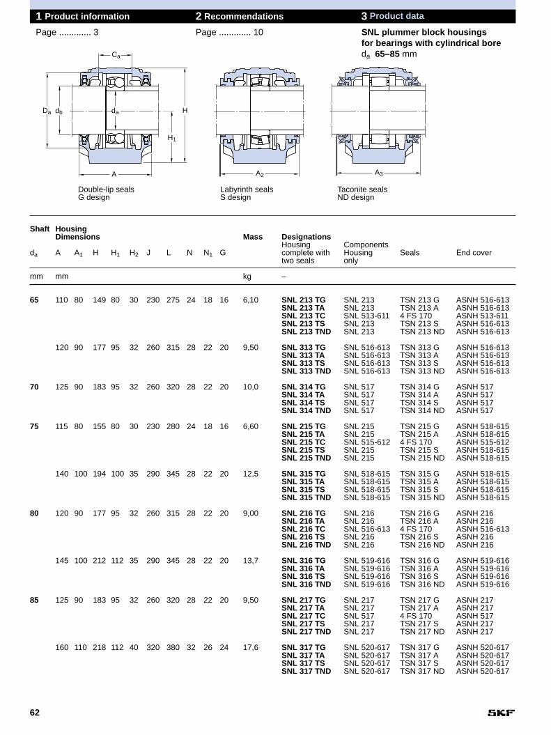
62
1 Product information 2 Recommendations 3 Product data
Page ............. 3 Page ............. 10 SNL plummer block housingsfor bearings with cylindrical boreda 65–85 mm
Shaft HousingDimensions Mass Designations
Housing Componentsda A A1 H H1 H2 J L N N1 G complete with Housing Seals End cover
two seals only
mm mm kg –
65 110 80 149 80 30 230 275 24 18 16 6,10 SNL 213 TG SNL 213 TSN 213 G ASNH 516-613SNL 213 TA SNL 213 TSN 213 A ASNH 516-613SNL 213 TC SNL 513-611 4 FS 170 ASNH 513-611SNL 213 TS SNL 213 TSN 213 S ASNH 516-613SNL 213 TND SNL 213 TSN 213 ND ASNH 516-613
120 90 177 95 32 260 315 28 22 20 9,50 SNL 313 TG SNL 516-613 TSN 313 G ASNH 516-613SNL 313 TA SNL 516-613 TSN 313 A ASNH 516-613SNL 313 TS SNL 516-613 TSN 313 S ASNH 516-613SNL 313 TND SNL 516-613 TSN 313 ND ASNH 516-613
70 125 90 183 95 32 260 320 28 22 20 10,0 SNL 314 TG SNL 517 TSN 314 G ASNH 517SNL 314 TA SNL 517 TSN 314 A ASNH 517SNL 314 TS SNL 517 TSN 314 S ASNH 517SNL 314 TND SNL 517 TSN 314 ND ASNH 517
75 115 80 155 80 30 230 280 24 18 16 6,60 SNL 215 TG SNL 215 TSN 215 G ASNH 518-615SNL 215 TA SNL 215 TSN 215 A ASNH 518-615SNL 215 TC SNL 515-612 4 FS 170 ASNH 515-612SNL 215 TS SNL 215 TSN 215 S ASNH 518-615SNL 215 TND SNL 215 TSN 215 ND ASNH 518-615
140 100 194 100 35 290 345 28 22 20 12,5 SNL 315 TG SNL 518-615 TSN 315 G ASNH 518-615SNL 315 TA SNL 518-615 TSN 315 A ASNH 518-615SNL 315 TS SNL 518-615 TSN 315 S ASNH 518-615SNL 315 TND SNL 518-615 TSN 315 ND ASNH 518-615
80 120 90 177 95 32 260 315 28 22 20 9,00 SNL 216 TG SNL 216 TSN 216 G ASNH 216SNL 216 TA SNL 216 TSN 216 A ASNH 216SNL 216 TC SNL 516-613 4 FS 170 ASNH 516-613SNL 216 TS SNL 216 TSN 216 S ASNH 216SNL 216 TND SNL 216 TSN 216 ND ASNH 216
145 100 212 112 35 290 345 28 22 20 13,7 SNL 316 TG SNL 519-616 TSN 316 G ASNH 519-616SNL 316 TA SNL 519-616 TSN 316 A ASNH 519-616SNL 316 TS SNL 519-616 TSN 316 S ASNH 519-616SNL 316 TND SNL 519-616 TSN 316 ND ASNH 519-616
85 125 90 183 95 32 260 320 28 22 20 9,50 SNL 217 TG SNL 217 TSN 217 G ASNH 217SNL 217 TA SNL 217 TSN 217 A ASNH 217SNL 217 TC SNL 517 4 FS 170 ASNH 517SNL 217 TS SNL 217 TSN 217 S ASNH 217SNL 217 TND SNL 217 TSN 217 ND ASNH 217
160 110 218 112 40 320 380 32 26 24 17,6 SNL 317 TG SNL 520-617 TSN 317 G ASNH 520-617SNL 317 TA SNL 520-617 TSN 317 A ASNH 520-617SNL 317 TS SNL 520-617 TSN 317 S ASNH 520-617SNL 317 TND SNL 520-617 TSN 317 ND ASNH 520-617
Double-lip seals Labyrinth seals Taconite sealsG design S design ND design
Ca
dadbDa
A
H
H1
A2 A3
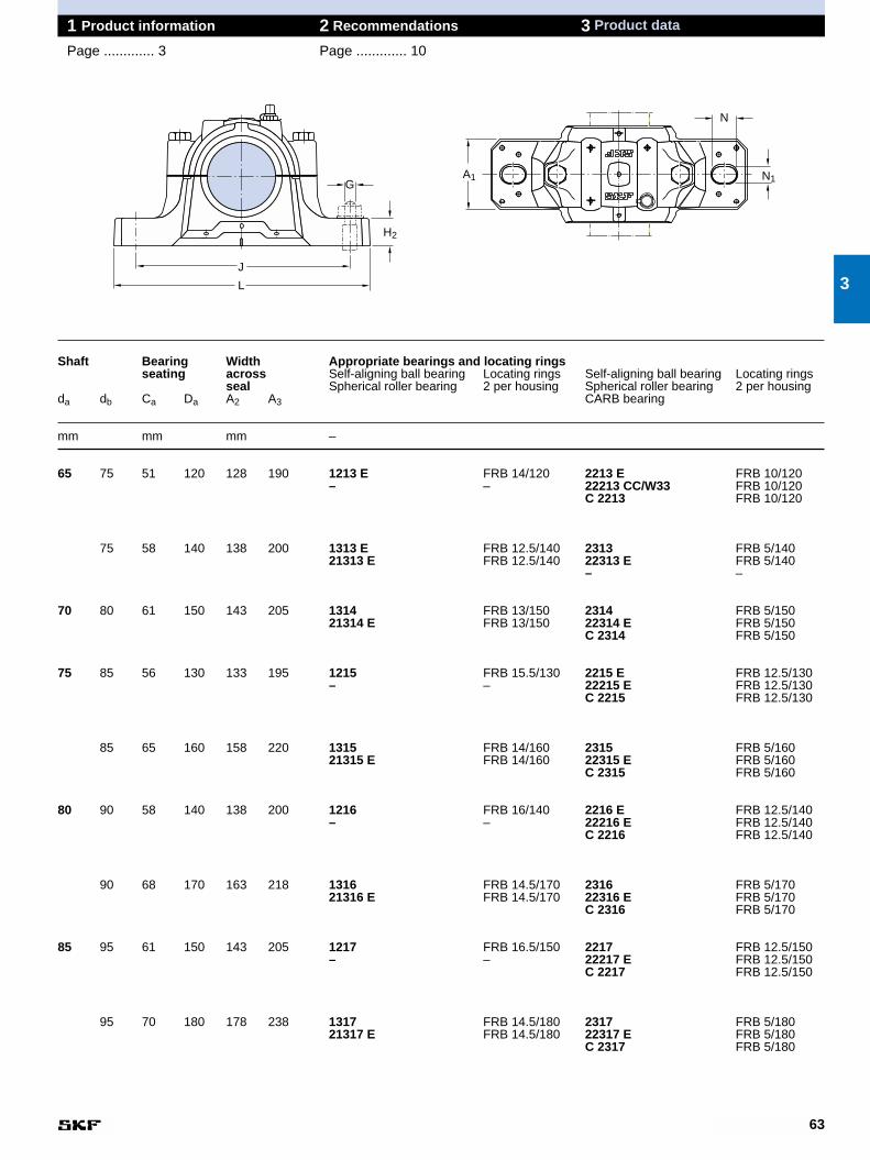
63
1 Product information 2 Recommendations 3 Product data
Page ............. 3 Page ............. 10
Shaft Bearing Width Appropriate bearings and locating ringsseating across Self-aligning ball bearing Locating rings Self-aligning ball bearing Locating rings
seal Spherical roller bearing 2 per housing Spherical roller bearing 2 per housingda db Ca Da A2 A3 CARB bearing
mm mm mm –
65 75 51 120 128 190 1213 E FRB 14/120 2213 E FRB 10/120– – 22213 CC/W33 FRB 10/120
C 2213 FRB 10/120
75 58 140 138 200 1313 E FRB 12.5/140 2313 FRB 5/14021313 E FRB 12.5/140 22313 E FRB 5/140
– –
70 80 61 150 143 205 1314 FRB 13/150 2314 FRB 5/15021314 E FRB 13/150 22314 E FRB 5/150
C 2314 FRB 5/150
75 85 56 130 133 195 1215 FRB 15.5/130 2215 E FRB 12.5/130– – 22215 E FRB 12.5/130
C 2215 FRB 12.5/130
85 65 160 158 220 1315 FRB 14/160 2315 FRB 5/16021315 E FRB 14/160 22315 E FRB 5/160
C 2315 FRB 5/160
80 90 58 140 138 200 1216 FRB 16/140 2216 E FRB 12.5/140– – 22216 E FRB 12.5/140
C 2216 FRB 12.5/140
90 68 170 163 218 1316 FRB 14.5/170 2316 FRB 5/17021316 E FRB 14.5/170 22316 E FRB 5/170
C 2316 FRB 5/170
85 95 61 150 143 205 1217 FRB 16.5/150 2217 FRB 12.5/150– – 22217 E FRB 12.5/150
C 2217 FRB 12.5/150
95 70 180 178 238 1317 FRB 14.5/180 2317 FRB 5/18021317 E FRB 14.5/180 22317 E FRB 5/180
C 2317 FRB 5/180
3
G
H2
L
J
N1A1
N
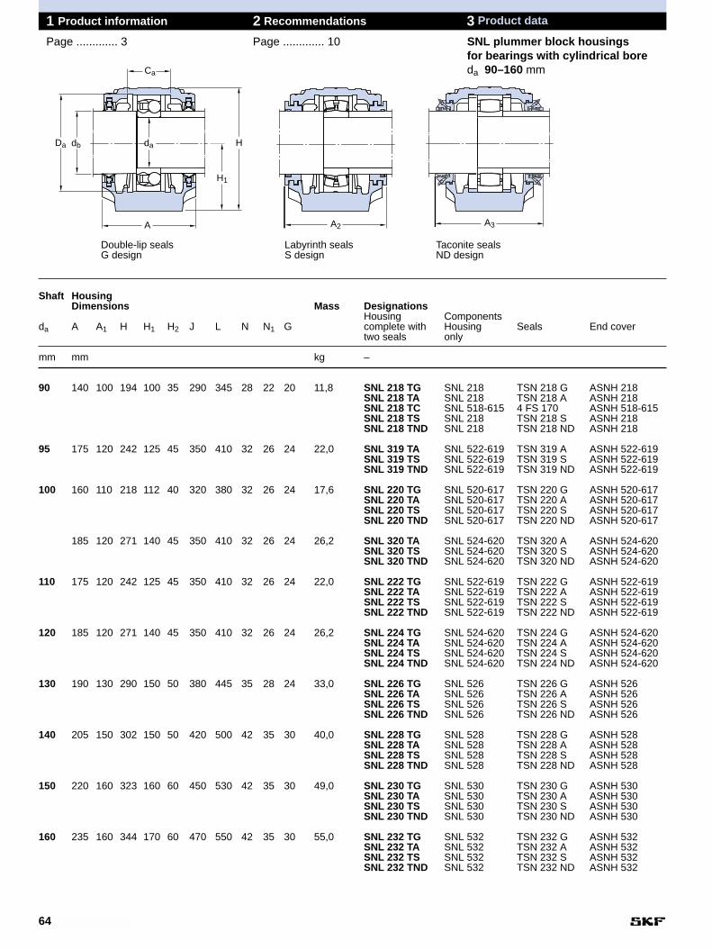
64
1 Product information 2 Recommendations 3 Product data
Page ............. 3 Page ............. 10 SNL plummer block housingsfor bearings with cylindrical boreda 90–160 mm
Shaft HousingDimensions Mass Designations
Housing Componentsda A A1 H H1 H2 J L N N1 G complete with Housing Seals End cover
two seals only
mm mm kg –
90 140 100 194 100 35 290 345 28 22 20 11,8 SNL 218 TG SNL 218 TSN 218 G ASNH 218SNL 218 TA SNL 218 TSN 218 A ASNH 218SNL 218 TC SNL 518-615 4 FS 170 ASNH 518-615SNL 218 TS SNL 218 TSN 218 S ASNH 218SNL 218 TND SNL 218 TSN 218 ND ASNH 218
95 175 120 242 125 45 350 410 32 26 24 22,0 SNL 319 TA SNL 522-619 TSN 319 A ASNH 522-619SNL 319 TS SNL 522-619 TSN 319 S ASNH 522-619SNL 319 TND SNL 522-619 TSN 319 ND ASNH 522-619
100 160 110 218 112 40 320 380 32 26 24 17,6 SNL 220 TG SNL 520-617 TSN 220 G ASNH 520-617SNL 220 TA SNL 520-617 TSN 220 A ASNH 520-617SNL 220 TS SNL 520-617 TSN 220 S ASNH 520-617SNL 220 TND SNL 520-617 TSN 220 ND ASNH 520-617
185 120 271 140 45 350 410 32 26 24 26,2 SNL 320 TA SNL 524-620 TSN 320 A ASNH 524-620SNL 320 TS SNL 524-620 TSN 320 S ASNH 524-620SNL 320 TND SNL 524-620 TSN 320 ND ASNH 524-620
110 175 120 242 125 45 350 410 32 26 24 22,0 SNL 222 TG SNL 522-619 TSN 222 G ASNH 522-619SNL 222 TA SNL 522-619 TSN 222 A ASNH 522-619SNL 222 TS SNL 522-619 TSN 222 S ASNH 522-619SNL 222 TND SNL 522-619 TSN 222 ND ASNH 522-619
120 185 120 271 140 45 350 410 32 26 24 26,2 SNL 224 TG SNL 524-620 TSN 224 G ASNH 524-620SNL 224 TA SNL 524-620 TSN 224 A ASNH 524-620SNL 224 TS SNL 524-620 TSN 224 S ASNH 524-620SNL 224 TND SNL 524-620 TSN 224 ND ASNH 524-620
130 190 130 290 150 50 380 445 35 28 24 33,0 SNL 226 TG SNL 526 TSN 226 G ASNH 526SNL 226 TA SNL 526 TSN 226 A ASNH 526SNL 226 TS SNL 526 TSN 226 S ASNH 526SNL 226 TND SNL 526 TSN 226 ND ASNH 526
140 205 150 302 150 50 420 500 42 35 30 40,0 SNL 228 TG SNL 528 TSN 228 G ASNH 528SNL 228 TA SNL 528 TSN 228 A ASNH 528SNL 228 TS SNL 528 TSN 228 S ASNH 528SNL 228 TND SNL 528 TSN 228 ND ASNH 528
150 220 160 323 160 60 450 530 42 35 30 49,0 SNL 230 TG SNL 530 TSN 230 G ASNH 530SNL 230 TA SNL 530 TSN 230 A ASNH 530SNL 230 TS SNL 530 TSN 230 S ASNH 530SNL 230 TND SNL 530 TSN 230 ND ASNH 530
160 235 160 344 170 60 470 550 42 35 30 55,0 SNL 232 TG SNL 532 TSN 232 G ASNH 532SNL 232 TA SNL 532 TSN 232 A ASNH 532SNL 232 TS SNL 532 TSN 232 S ASNH 532SNL 232 TND SNL 532 TSN 232 ND ASNH 532
Double-lip seals Labyrinth seals Taconite sealsG design S design ND design
Ca
dadbDa
A
H
H1
A2 A3
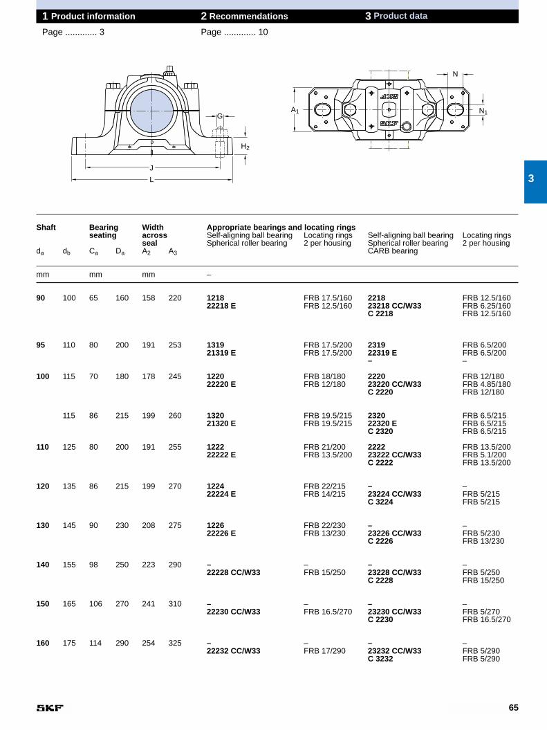
65
1 Product information 2 Recommendations 3 Product data
Page ............. 3 Page ............. 10
Shaft Bearing Width Appropriate bearings and locating ringsseating across Self-aligning ball bearing Locating rings Self-aligning ball bearing Locating rings
seal Spherical roller bearing 2 per housing Spherical roller bearing 2 per housingda db Ca Da A2 A3 CARB bearing
mm mm mm –
90 100 65 160 158 220 1218 FRB 17.5/160 2218 FRB 12.5/16022218 E FRB 12.5/160 23218 CC/W33 FRB 6.25/160
C 2218 FRB 12.5/160
95 110 80 200 191 253 1319 FRB 17.5/200 2319 FRB 6.5/20021319 E FRB 17.5/200 22319 E FRB 6.5/200
– –
100 115 70 180 178 245 1220 FRB 18/180 2220 FRB 12/18022220 E FRB 12/180 23220 CC/W33 FRB 4.85/180
C 2220 FRB 12/180
115 86 215 199 260 1320 FRB 19.5/215 2320 FRB 6.5/21521320 E FRB 19.5/215 22320 E FRB 6.5/215
C 2320 FRB 6.5/215
110 125 80 200 191 255 1222 FRB 21/200 2222 FRB 13.5/20022222 E FRB 13.5/200 23222 CC/W33 FRB 5.1/200
C 2222 FRB 13.5/200
120 135 86 215 199 270 1224 FRB 22/215 – –22224 E FRB 14/215 23224 CC/W33 FRB 5/215
C 3224 FRB 5/215
130 145 90 230 208 275 1226 FRB 22/230 – –22226 E FRB 13/230 23226 CC/W33 FRB 5/230
C 2226 FRB 13/230
140 155 98 250 223 290 – – – –22228 CC/W33 FRB 15/250 23228 CC/W33 FRB 5/250
C 2228 FRB 15/250
150 165 106 270 241 310 – – – –22230 CC/W33 FRB 16.5/270 23230 CC/W33 FRB 5/270
C 2230 FRB 16.5/270
160 175 114 290 254 325 – – – –22232 CC/W33 FRB 17/290 23232 CC/W33 FRB 5/290
C 3232 FRB 5/290
3
G
H2
L
J
N1A1
N
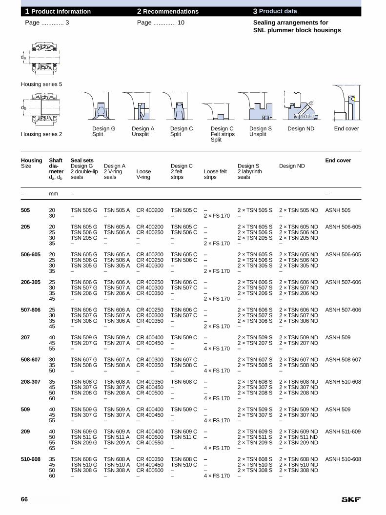
66
1 Product information 2 Recommendations 3 Product data
Page ............. 3 Page ............. 10 Sealing arrangements forSNL plummer block housings
Housing Shaft Seal sets End coverSize dia- Design G Design A Design C Design S Design ND
meter 2 double-lip 2 V-ring Loose 2 felt Loose felt 2 labyrinthda, db seals seals V-ring strips strips seals
– mm – –
505 20 TSN 505 G TSN 505 A CR 400200 TSN 505 C – 2 × TSN 505 S 2 × TSN 505 ND ASNH 50530 – – – – 2 × FS 170 – –
205 20 TSN 605 G TSN 605 A CR 400200 TSN 605 C – 2 × TSN 605 S 2 × TSN 605 ND ASNH 506-60525 TSN 506 G TSN 506 A CR 400250 TSN 506 C – 2 × TSN 506 S 2 × TSN 506 ND30 TSN 205 G – – – – 2 × TSN 205 S 2 × TSN 205 ND35 – – – – 2 × FS 170 – –
506-605 20 TSN 605 G TSN 605 A CR 400200 TSN 605 C – 2 × TSN 605 S 2 × TSN 605 ND ASNH 506-60525 TSN 506 G TSN 506 A CR 400250 TSN 506 C – 2 × TSN 506 S 2 × TSN 506 ND30 TSN 305 G TSN 305 A CR 400300 – – 2 × TSN 305 S 2 × TSN 305 ND35 – – – – 2 × FS 170 – –
206-305 25 TSN 606 G TSN 606 A CR 400250 TSN 606 C – 2 × TSN 606 S 2 × TSN 606 ND ASNH 507-60630 TSN 507 G TSN 507 A CR 400300 TSN 507 C – 2 × TSN 507 S 2 × TSN 507 ND35 TSN 206 G TSN 206 A CR 400350 – – 2 × TSN 206 S 2 × TSN 206 ND45 – – – – 2 × FS 170 – –
507-606 25 TSN 606 G TSN 606 A CR 400250 TSN 606 C – 2 × TSN 606 S 2 × TSN 606 ND ASNH 507-60630 TSN 507 G TSN 507 A CR 400300 TSN 507 C – 2 × TSN 507 S 2 × TSN 507 ND35 TSN 306 G TSN 306 A CR 400350 – – 2 × TSN 306 S 2 × TSN 306 ND45 – – – – 2 × FS 170 – –
207 40 TSN 509 G TSN 509 A CR 400400 TSN 509 C – 2 × TSN 509 S 2 × TSN 509 ND ASNH 50945 TSN 207 G TSN 207 A CR 400450 – – 2 × TSN 207 S 2 × TSN 207 ND55 – – – – 4 × FS 170 – –
508-607 30 TSN 607 G TSN 607 A CR 400300 TSN 607 C – 2 × TSN 607 S 2 × TSN 607 ND ASNH 508-60735 TSN 508 G TSN 508 A CR 400350 TSN 508 C – 2 × TSN 508 S 2 × TSN 508 ND50 – – – – 4 × FS 170 – –
208-307 35 TSN 608 G TSN 608 A CR 400350 TSN 608 C – 2 × TSN 608 S 2 × TSN 608 ND ASNH 510-60845 TSN 307 G TSN 307 A CR 400450 – – 2 × TSN 307 S 2 × TSN 307 ND50 TSN 208 G TSN 208 A CR 400500 – – 2 × TSN 208 S 2 × TSN 208 ND60 – – – – 4 × FS 170 – –
509 40 TSN 509 G TSN 509 A CR 400400 TSN 509 C – 2 × TSN 509 S 2 × TSN 509 ND ASNH 50945 TSN 307 G TSN 307 A CR 400450 – – 2 × TSN 307 S 2 × TSN 307 ND55 – – – – 4 × FS 170 – –
209 40 TSN 609 G TSN 609 A CR 400400 TSN 609 C – 2 × TSN 609 S 2 × TSN 609 ND ASNH 511-60950 TSN 511 G TSN 511 A CR 400500 TSN 511 C – 2 × TSN 511 S 2 × TSN 511 ND55 TSN 209 G TSN 209 A CR 400550 – – 2 × TSN 209 S 2 × TSN 209 ND65 – – – – 4 × FS 170 – –
510-608 35 TSN 608 G TSN 608 A CR 400350 TSN 608 C – 2 × TSN 608 S 2 × TSN 608 ND ASNH 510-60845 TSN 510 G TSN 510 A CR 400450 TSN 510 C – 2 × TSN 510 S 2 × TSN 510 ND50 TSN 308 G TSN 308 A CR 400500 – – 2 × TSN 308 S 2 × TSN 308 ND60 – – – – 4 × FS 170 – –
Design G Design A Design C Design C Design S Design ND End coverHousing series 2 Split Unsplit Split Felt strips Unsplit
Split
Housing series 5
da
db
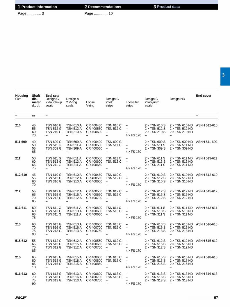
67
1 Product information 2 Recommendations 3 Product data
Page ............. 3 Page ............. 10
Housing Shaft Seal sets End coverSize dia- Design G Design A Design C Design S Design ND
meter 2 double-lip 2 V-ring Loose 2 felt Loose felt 2 labyrinthda, db seals seals V-ring strips strips seals
– mm – –
210 45 TSN 610 G TSN 610 A CR 400450 TSN 610 C – 2 × TSN 610 S 2 × TSN 610 ND ASNH 512-61055 TSN 512 G TSN 512 A CR 400550 TSN 512 C – 2 × TSN 512 S 2 × TSN 512 ND60 TSN 210 G TSN 210 A CR 400600 – – 2 × TSN 210 S 2 × TSN 210 ND70 – – – – 4 × FS 170 – –
511-609 40 TSN 609 G TSN 609 A CR 400400 TSN 609 C – 2 × TSN 609 S 2 × TSN 609 ND ASNH 511-60950 TSN 511 G TSN 511 A CR 400500 TSN 511 C – 2 × TSN 511 S 2 × TSN 511 ND55 TSN 309 G TSN 309 A CR 400550 – – 2 × TSN 309 S 2 × TSN 309 ND65 – – – – 4 × FS 170 – –
211 50 TSN 611 G TSN 611 A CR 400500 TSN 611 C – 2 × TSN 611 S 2 × TSN 611 ND ASNH 513-61160 TSN 513 G TSN 513 A CR 400600 TSN 513 C – 2 × TSN 513 S 2 × TSN 513 ND65 TSN 211 G TSN 211 A CR 400650 – – 2 × TSN 211 S 2 × TSN 211 ND75 – – – – 4 × FS 170 – –
512-610 45 TSN 610 G TSN 610 A CR 400450 TSN 610 C – 2 × TSN 610 S 2 × TSN 610 ND ASNH 512-61055 TSN 512 G TSN 512 A CR 400550 TSN 512 C – 2 × TSN 512 S 2 × TSN 512 ND60 TSN 310 G TSN 310 A CR 400600 – – 2 × TSN 310 S 2 × TSN 310 ND70 – – – – 4 × FS 170 – –
212 55 TSN 612 G TSN 612 A CR 400550 TSN 612 C – 2 × TSN 612 S 2 × TSN 612 ND ASNH 515-61265 TSN 515 G TSN 515 A CR 400650 TSN 515 C – 2 × TSN 515 S 2 × TSN 515 ND70 TSN 212 G TSN 212 A CR 400700 – – 2 × TSN 212 S 2 × TSN 212 ND85 – – – – 4 × FS 170 – –
513-611 50 TSN 611 G TSN 611 A CR 400500 TSN 611 C – 2 × TSN 611 S 2 × TSN 611 ND ASNH 513-61160 TSN 513 G TSN 513 A CR 400600 TSN 513 C – 2 × TSN 513 S 2 × TSN 513 ND65 TSN 311 G TSN 311 A CR 400650 – – 2 × TSN 311 S 2 × TSN 311 ND75 – – – – 4 × FS 170 – –
213 60 TSN 613 G TSN 613 A CR 400600 TSN 613 C – 2 × TSN 613 S 2 × TSN 613 ND ASNH 516-61370 TSN 516 G TSN 516 A CR 400700 TSN 516 C – 2 × TSN 516 S 2 × TSN 516 ND75 TSN 213 G TSN 213 A CR 400750 – – 2 × TSN 213 S 2 × TSN 213 ND90 – – – – 4 × FS 170 – –
515-612 55 TSN 612 G TSN 612 A CR 400550 TSN 612 C – 2 × TSN 612 S 2 × TSN 612 ND ASNH 515-61265 TSN 515 G TSN 515 A CR 400650 TSN 515 C – 2 × TSN 515 S 2 × TSN 515 ND70 TSN 312 G TSN 312 A CR 400700 – – 2 × TSN 312 S 2 × TSN 312 ND85 – – – – 4 × FS 170 – –
215 65 TSN 615 G TSN 615 A CR 400650 TSN 615 C – 2 × TSN 615 S 2 × TSN 615 ND ASNH 518-61580 TSN 518 G TSN 518 A CR 400800 TSN 518 C – 2 × TSN 518 S 2 × TSN 518 ND85 TSN 215 G TSN 215 A CR 400850 – – 2 × TSN 215 S 2 × TSN 215 ND100 – – – – 4 × FS 170 – –
516-613 60 TSN 613 G TSN 613 A CR 400600 TSN 613 C – 2 × TSN 613 S 2 × TSN 613 ND ASNH 516-61370 TSN 516 G TSN 516 A CR 400700 TSN 516 C – 2 × TSN 516 S 2 × TSN 516 ND75 TSN 313 G TSN 313 A CR 400750 – – 2 × TSN 313 S 2 × TSN 313 ND90 – – – – 4 × FS 170 – –
3
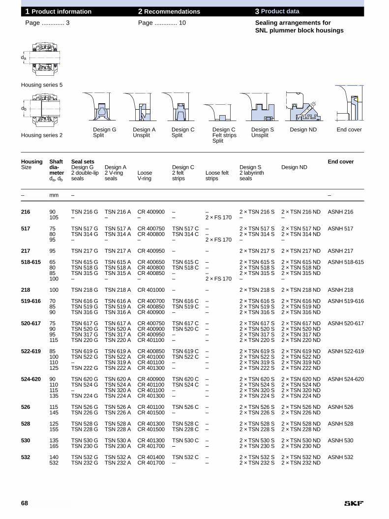
68
1 Product information 2 Recommendations 3 Product data
Page ............. 3 Page ............. 10 Sealing arrangements forSNL plummer block housings
Housing Shaft Seal sets End coverSize dia- Design G Design A Design C Design S Design ND
meter 2 double-lip 2 V-ring Loose 2 felt Loose felt 2 labyrinthda, db seals seals V-ring strips strips seals
– mm – –
216 90 TSN 216 G TSN 216 A CR 400900 – – 2 × TSN 216 S 2 × TSN 216 ND ASNH 216105 – – – – 2 × FS 170 – –
517 75 TSN 517 G TSN 517 A CR 400750 TSN 517 C – 2 × TSN 517 S 2 × TSN 517 ND ASNH 51780 TSN 314 G TSN 314 A CR 400800 TSN 314 C – 2 × TSN 314 S 2 × TSN 314 ND95 – – – – 2 × FS 170 – –
217 95 TSN 217 G TSN 217 A CR 400950 – – 2 × TSN 217 S 2 × TSN 217 ND ASNH 217
518-615 65 TSN 615 G TSN 615 A CR 400650 TSN 615 C – 2 × TSN 615 S 2 × TSN 615 ND ASNH 518-61580 TSN 518 G TSN 518 A CR 400800 TSN 518 C – 2 × TSN 518 S 2 × TSN 518 ND85 TSN 315 G TSN 315 A CR 400850 – – 2 × TSN 315 S 2 × TSN 315 ND100 – – – – 2 × FS 170 – –
218 100 TSN 218 G TSN 218 A CR 401000 – – 2 × TSN 218 S 2 × TSN 218 ND ASNH 218
519-616 70 TSN 616 G TSN 616 A CR 400700 TSN 616 C – 2 × TSN 616 S 2 × TSN 616 ND ASNH 519-61685 TSN 519 G TSN 519 A CR 400850 TSN 519 C – 2 × TSN 519 S 2 × TSN 519 ND90 TSN 316 G TSN 316 A CR 400900 – – 2 × TSN 316 S 2 × TSN 316 ND
520-617 75 TSN 617 G TSN 617 A CR 400750 TSN 617 C – 2 × TSN 617 S 2 × TSN 617 ND ASNH 520-617 90 TSN 520 G TSN 520 A CR 400900 TSN 520 C – 2 × TSN 520 S 2 × TSN 520 ND95 TSN 317 G TSN 317 A CR 400950 – – 2 × TSN 317 S 2 × TSN 317 ND115 TSN 220 G TSN 220 A CR 401100 – – 2 × TSN 220 S 2 × TSN 220 ND
522-619 85 TSN 619 G TSN 619 A CR 400850 TSN 619 C – 2 × TSN 619 S 2 × TSN 619 ND ASNH 522-619100 TSN 522 G TSN 522 A CR 401000 TSN 522 C – 2 × TSN 522 S 2 × TSN 522 ND110 – TSN 319 A CR 401100 – – 2 × TSN 319 S 2 × TSN 319 ND125 TSN 222 G TSN 222 A CR 401300 – – 2 × TSN 222 S 2 × TSN 222 ND
524-620 90 TSN 620 G TSN 620 A CR 400900 TSN 620 C – 2 × TSN 620 S 2 × TSN 620 ND ASNH 524-620110 TSN 524 G TSN 524 A CR 401100 TSN 524 C – 2 × TSN 524 S 2 × TSN 524 ND115 – TSN 320 A CR 401100 – – 2 × TSN 320 S 2 × TSN 320 ND135 TSN 224 G TSN 224 A CR 401300 – – 2 × TSN 224 S 2 × TSN 224 ND
526 115 TSN 526 G TSN 526 A CR 401100 TSN 526 C – 2 × TSN 526 S 2 × TSN 526 ND ASNH 526 145 TSN 226 G TSN 226 A CR 401500 – – 2 × TSN 226 S 2 × TSN 226 ND
528 125 TSN 528 G TSN 528 A CR 401300 TSN 528 C – 2 × TSN 528 S 2 × TSN 528 ND ASNH 528 155 TSN 228 G TSN 228 A CR 401500 TSN 228 C – 2 × TSN 228 S 2 × TSN 228 ND
530 135 TSN 530 G TSN 530 A CR 401300 TSN 530 C – 2 × TSN 530 S 2 × TSN 530 ND ASNH 530 165 TSN 230 G TSN 230 A CR 401700 – – 2 × TSN 230 S 2 × TSN 230 ND
532 140 TSN 532 G TSN 532 A CR 401400 TSN 532 C – 2 × TSN 532 S 2 × TSN 532 ND ASNH 532 532 TSN 232 G TSN 232 A CR 401700 – – 2 × TSN 232 S 2 × TSN 232 ND
Design G Design A Design C Design C Design S Design ND End coverHousing series 2 Split Unsplit Split Felt strips Unsplit
Split
Housing series 5
da
db

69
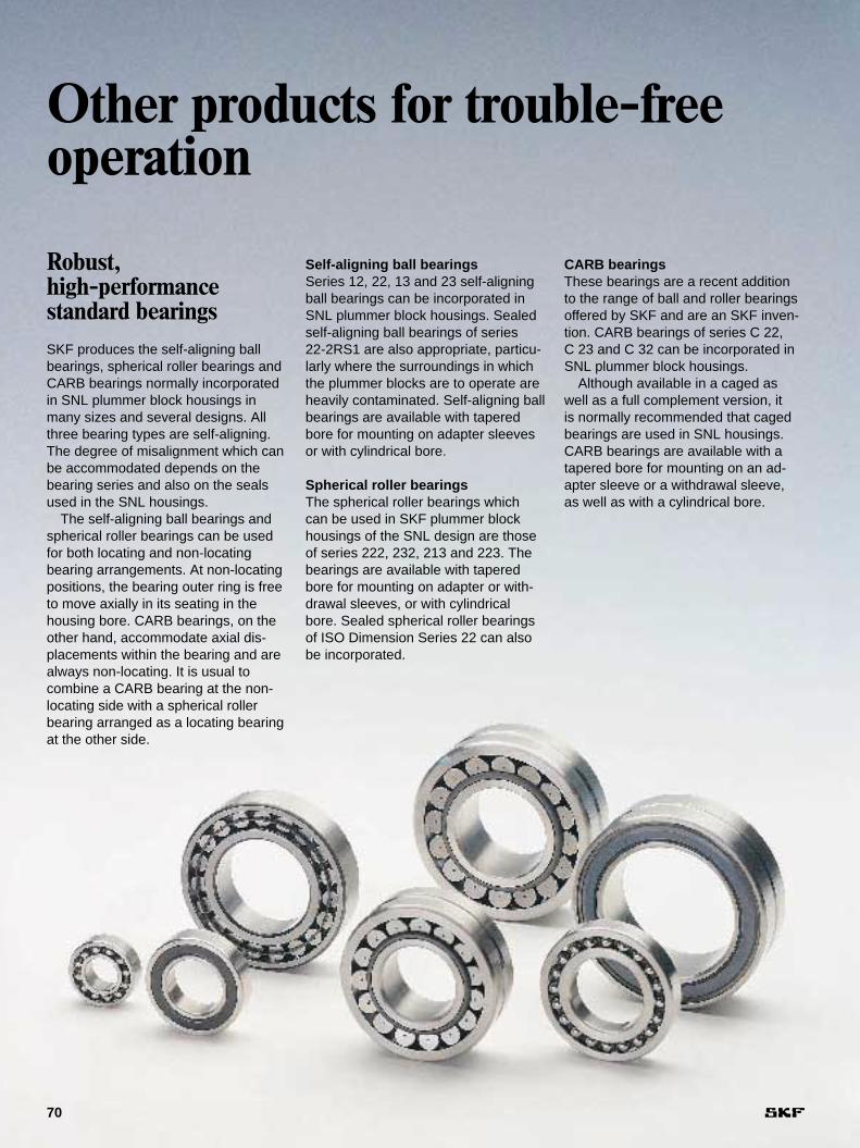
CARB bearingsThese bearings are a recent additionto the range of ball and roller bearingsoffered by SKF and are an SKF inven-tion. CARB bearings of series C 22, C 23 and C 32 can be incorporated inSNL plummer block housings.
Although available in a caged aswell as a full complement version, it is normally recommended that cagedbearings are used in SNL housings.CARB bearings are available with atapered bore for mounting on an ad-apter sleeve or a withdrawal sleeve, as well as with a cylindrical bore.
Self-aligning ball bearingsSeries 12, 22, 13 and 23 self-aligningball bearings can be incorporated inSNL plummer block housings. Sealedself-aligning ball bearings of series 22-2RS1 are also appropriate, particu-larly where the surroundings in whichthe plummer blocks are to operate areheavily contaminated. Self-aligning ballbearings are available with taperedbore for mounting on adapter sleevesor with cylindrical bore.
Spherical roller bearings The spherical roller bearings whichcan be used in SKF plummer blockhousings of the SNL design are thoseof series 222, 232, 213 and 223. Thebearings are available with taperedbore for mounting on adapter or with-drawal sleeves, or with cylindricalbore. Sealed spherical roller bearingsof ISO Dimension Series 22 can alsobe incorporated.
Other products for trouble-freeoperation
70
Robust, high-performance standard bearingsSKF produces the self-aligning ballbearings, spherical roller bearings andCARB bearings normally incorporatedin SNL plummer block housings inmany sizes and several designs. Allthree bearing types are self-aligning.The degree of misalignment which canbe accommodated depends on thebearing series and also on the sealsused in the SNL housings.
The self-aligning ball bearings andspherical roller bearings can be usedfor both locating and non-locatingbearing arrangements. At non-locatingpositions, the bearing outer ring is freeto move axially in its seating in thehousing bore. CARB bearings, on theother hand, accommodate axial dis-placements within the bearing and arealways non-locating. It is usual to combine a CARB bearing at the non-locating side with a spherical rollerbearing arranged as a locating bearingat the other side.
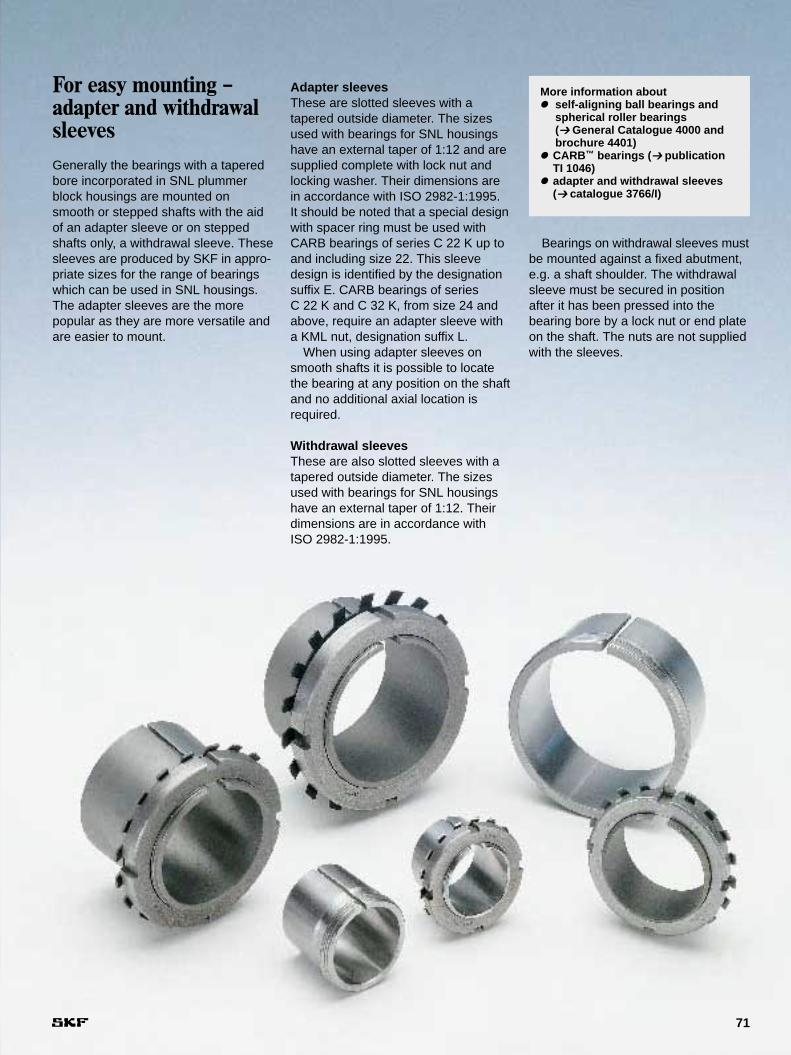
Adapter sleevesThese are slotted sleeves with a tapered outside diameter. The sizesused with bearings for SNL housingshave an external taper of 1:12 and aresupplied complete with lock nut andlocking washer. Their dimensions arein accordance with ISO 2982-1:1995. It should be noted that a special designwith spacer ring must be used withCARB bearings of series C 22 K up toand including size 22. This sleevedesign is identified by the designationsuffix E. CARB bearings of series C 22 K and C 32 K, from size 24 andabove, require an adapter sleeve witha KML nut, designation suffix L.
When using adapter sleeves onsmooth shafts it is possible to locatethe bearing at any position on the shaftand no additional axial location isrequired.
Withdrawal sleevesThese are also slotted sleeves with atapered outside diameter. The sizesused with bearings for SNL housingshave an external taper of 1:12. Theirdimensions are in accordance withISO 2982-1:1995.
71
For easy mounting –adapter and withdrawalsleevesGenerally the bearings with a taperedbore incorporated in SNL plummerblock housings are mounted onsmooth or stepped shafts with the aidof an adapter sleeve or on steppedshafts only, a withdrawal sleeve. Thesesleeves are produced by SKF in appro-priate sizes for the range of bearingswhich can be used in SNL housings.The adapter sleeves are the more popular as they are more versatile andare easier to mount.
More information about● self-aligning ball bearings and
spherical roller bearings(➔ General Catalogue 4000 andbrochure 4401)
● CARB™ bearings (➔ publication TI 1046)
● adapter and withdrawal sleeves(➔ catalogue 3766/I)
Bearings on withdrawal sleeves mustbe mounted against a fixed abutment,e.g. a shaft shoulder. The withdrawalsleeve must be secured in positionafter it has been pressed into the bearing bore by a lock nut or end plateon the shaft. The nuts are not suppliedwith the sleeves.
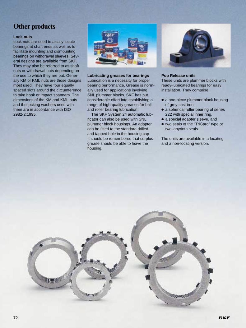
Pop Release unitsThese units are plummer blocks withready-lubricated bearings for easyinstallation. They comprise
● a one-piece plummer block housingof grey cast iron,
● a spherical roller bearing of series222 with special inner ring,
● a special adapter sleeve, and● two seals of the “TriGard” type or
two labyrinth seals.
The units are available in a locatingand a non-locating version.
Lubricating greases for bearingsLubrication is a necessity for properbearing performance. Grease is norm-ally used for applications involvingSNL plummer blocks. SKF has putconsiderable effort into establishing arange of high-quality greases for balland roller bearing lubrication.
The SKF System 24 automatic lub-ricator can also be used with SNLplummer block housings. An adaptercan be fitted to the standard drilled and tapped hole in the housing cap. It should be remembered that surplusgrease should be able to leave thehousing.
72
Other productsLock nutsLock nuts are used to axially locatebearings at shaft ends as well as tofacilitate mounting and dismountingbearings on withdrawal sleeves. Sev-eral designs are available from SKF.They may also be referred to as shaftnuts or withdrawal nuts depending onthe use to which they are put. Gener-ally KM or KML nuts are those designsmost used. They have four equallyspaced slots around the circumferenceto take hook or impact spanners. Thedimensions of the KM and KML nutsand the locking washers used withthem are in accordance with ISO2982-2:1995.
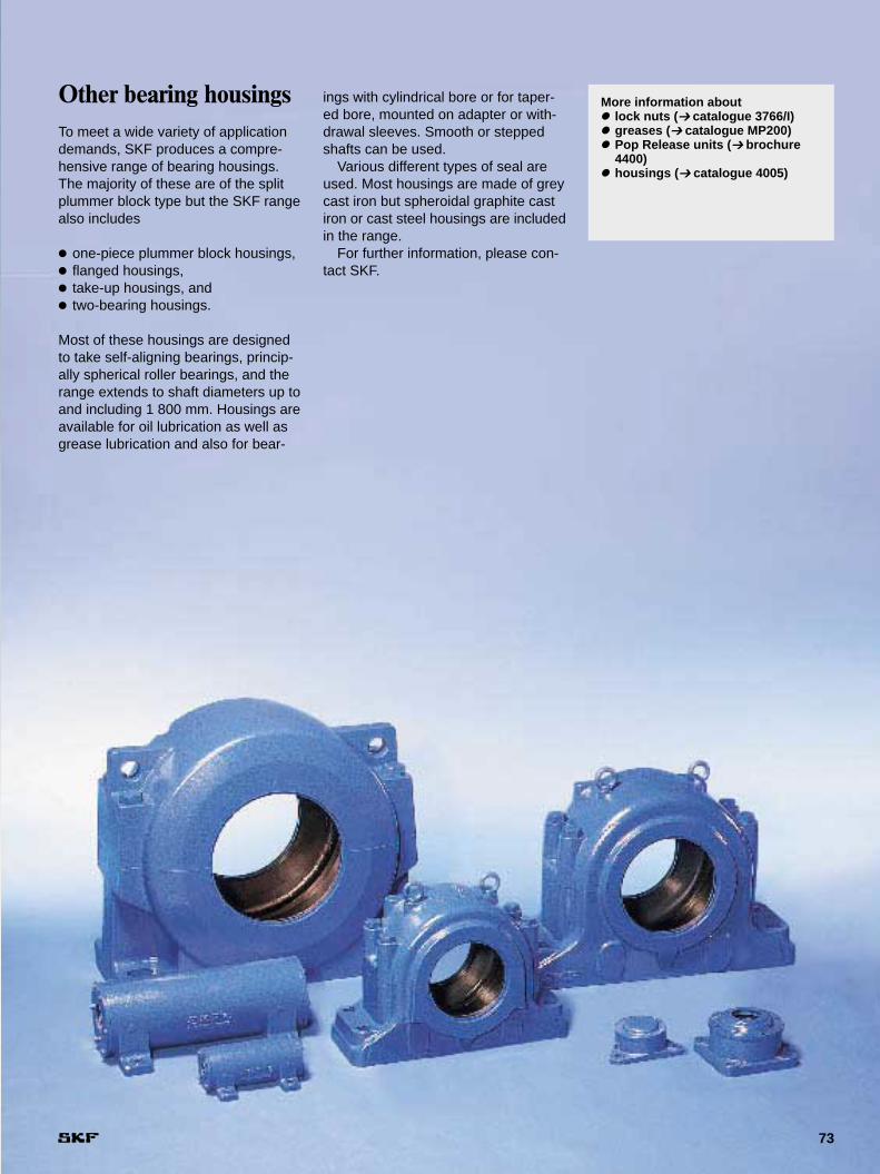
73
Other bearing housingsTo meet a wide variety of applicationdemands, SKF produces a compre-hensive range of bearing housings.The majority of these are of the splitplummer block type but the SKF rangealso includes
● one-piece plummer block housings,● flanged housings,● take-up housings, and● two-bearing housings.
Most of these housings are designedto take self-aligning bearings, princip-ally spherical roller bearings, and therange extends to shaft diameters up toand including 1 800 mm. Housings areavailable for oil lubrication as well asgrease lubrication and also for bear-
ings with cylindrical bore or for taper-ed bore, mounted on adapter or with-drawal sleeves. Smooth or steppedshafts can be used.
Various different types of seal areused. Most housings are made of greycast iron but spheroidal graphite castiron or cast steel housings are includedin the range.
For further information, please con-tact SKF.
More information about● lock nuts (➔ catalogue 3766/I)● greases (➔ catalogue MP200)● Pop Release units (➔ brochure
4400)● housings (➔ catalogue 4005)
The SKF Group– a worldwide corporation
74
SKF is an international industrial Groupoperating in some 130 countries and isworld leader in bearings.
The company was founded in 1907following the invention of the self-align-ing ball bearing by Sven Wingquist and,after only a few years, SKF began toexpand all over the world.
Today, SKF has some 45 000 em-ployees and around 80 manufacturingfacilities spread throughout the world.An international sales network includesa large number of sales companies andsome 7 000 distributors and retailers.Worldwide availability of SKF productsis supported by a comprehensive technical advisory service.
The key to success has been a con-sistent emphasis on maintaining thehighest quality of its products and services. Continuous invest-ment in research and
development has also played a vitalrole, resulting in many examples ofepoch-making innovations.
The business of the Group consistsof bearings, seals, special steel and acomprehensive range of other high-tech industrial components. The experi-ence gained in these various fieldsprovides SKF with the essential know-ledge and expertise required in orderto provide the customers with the mostadvanced engineering products andefficient service.