Embed Size (px)
Citation preview

Version 6.8
Version 6.8 November 2014
Document # LTRT-52323
Session Border Controllers (SBC)
Multi-Service Business Routers (MSBR)
VoIP Analog & Digital Media Gateways
SNMP Reference Guide For MediaPack™ 1xx & Mediant™ Series
Version 6.8


SNMP Reference Guide Contents
Version 6.8 3 MediaPack & Mediant Series
Table of Contents 1 Introduction ....................................................................................................... 13
1.1 Product Naming Convention .................................................................................. 13
2 SNMP Overview ................................................................................................ 15
2.1 SNMP Standards and Objects ............................................................................... 15 2.1.1 SNMP Message Standard ...................................................................................... 15 2.1.2 SNMP MIB Objects ................................................................................................. 16 2.1.3 SNMP Extensibility Feature .................................................................................... 17
2.2 TrunkPack-VoP Series Supported MIBs ................................................................ 17 2.3 SNMP Interface Details .......................................................................................... 22
2.3.1 SNMP Community Names ...................................................................................... 22 2.3.1.1 Configuring Community Strings via the Web ........................................... 22 2.3.1.2 Configuring Community Strings via the ini File ........................................ 22 2.3.1.3 Configuring Community Strings via SNMP .............................................. 22
2.3.2 SNMPv3 USM Users............................................................................................... 24 2.3.2.1 Configuring SNMPv3 Users via the ini File ............................................. 25 2.3.2.2 Configuring SNMPv3 Users via SNMP ................................................... 26
2.3.3 Trusted Managers ................................................................................................... 27 2.3.3.1 Configuring Trusted Managers via ini File ............................................... 27 2.3.3.2 Configuring Trusted Managers via SNMP ............................................... 27
2.3.4 SNMP Ports ............................................................................................................ 28 2.3.5 Multiple SNMP Trap Destinations ........................................................................... 28
2.3.5.1 Configuring Trap Managers via Host Name ............................................ 28 2.3.5.2 Configuring Trap Managers via ini File .................................................... 29 2.3.5.3 Configuring SNMP Engine ID .................................................................. 30 2.3.5.4 Configuring Trap Managers via SNMP .................................................... 30
3 Carrier-Grade Alarm System ........................................................................... 33
3.1 Active Alarm Table ................................................................................................. 33 3.2 Alarm History .......................................................................................................... 33 3.3 SONET Alarm Consolidation .................................................................................. 34 3.4 ISDN Alarm Consolidation ...................................................................................... 34
4 Topology MIB Objects ...................................................................................... 35
4.1 Physical Entity (RFC 2737) .................................................................................... 35 4.2 IF-MIB (RFC 2863) ................................................................................................. 35
4.2.1 Ethernet Interface.................................................................................................... 35 4.2.2 DS1 Interface .......................................................................................................... 37 4.2.3 BRI Interface ........................................................................................................... 38 4.2.4 ADSL/VDSL Interface ............................................................................................. 39 4.2.5 DS3 Interface .......................................................................................................... 40 4.2.6 SONET/SDH Interface ............................................................................................ 41 4.2.7 VLAN Interface ........................................................................................................ 42
4.3 MIB-II Counters ...................................................................................................... 43
5 File Management .............................................................................................. 45
5.1 Downloading a File to the Device ........................................................................... 45 5.2 Uploading and Deleting a File ................................................................................ 45
6 Performance Measurements ............................................................................ 47
6.1 Total Counters ........................................................................................................ 48

MediaPack & Mediant Series
SNMP Reference Guide 4 Document #: LTRT-52379
6.2 SNMP Performance Monitoring MIBs .................................................................... 48 6.2.1 IP Network Interface ............................................................................................... 49 6.2.2 Media Realms ......................................................................................................... 50 6.2.3 VoIP Calls ............................................................................................................... 52 6.2.4 SIP IP-to-Tel and Tel-to-IP Calls ............................................................................. 54 6.2.5 DS3 ......................................................................................................................... 57 6.2.6 Fiber Group ............................................................................................................. 58 6.2.7 High Availability ....................................................................................................... 59 6.2.8 SIP Messages ......................................................................................................... 60 6.2.9 SBC Sessions ......................................................................................................... 61 6.2.10 SBC Admission Control .......................................................................................... 62 6.2.11 Trunk Groups .......................................................................................................... 65 6.2.12 Trunks ..................................................................................................................... 67 6.2.13 Data Networking ...................................................................................................... 68 6.2.14 Survivable Branch Appliance (SBA) ....................................................................... 69 6.2.15 Non-SIP Protocol .................................................................................................... 71
7 SNMP Traps ...................................................................................................... 73
7.1 Standard Traps ....................................................................................................... 73 7.2 Proprietary Traps .................................................................................................... 73
7.2.1 Trap Varbinds .......................................................................................................... 74 7.2.2 Customizing Trap's Enterprise OID ........................................................................ 74 7.2.3 SNMP Alarms in Syslog .......................................................................................... 75
7.3 Device Alarms ........................................................................................................ 76 7.3.1 Chassis Alarms ....................................................................................................... 76
7.3.1.1 Fan Tray Alarm ........................................................................................ 76 7.3.1.2 Power Supply Alarm ................................................................................ 77 7.3.1.3 User Input Alarm ...................................................................................... 78 7.3.1.4 PEM Alarm ............................................................................................... 78 7.3.1.5 Hardware Failure Alarm (Mediant 1000) ................................................. 79 7.3.1.6 Hardware Failure Alarm (Mediant 3000) ................................................. 79
7.3.2 Timing Module Alarms ............................................................................................ 80 7.3.2.1 TM Inconsistent Remote and Local PLL Status Alarm ............................ 80 7.3.2.2 TM Reference Status Alarm .................................................................... 81 7.3.2.3 TM Reference Change Alarm .................................................................. 81
7.3.3 Trunk Alarms ........................................................................................................... 82 7.3.3.1 Trunk Near-End LOS Alarm .................................................................... 82 7.3.3.2 Trunk Near-End LOF Alarm ..................................................................... 82 7.3.3.3 Trunk AIS Alarm ...................................................................................... 83 7.3.3.4 Trunk Far-End LOF Alarm ....................................................................... 83 7.3.3.5 DS1 Line Status Alarm ............................................................................ 84 7.3.3.6 B-Channel Alarm ..................................................................................... 85 7.3.3.7 NFAS Group Alarm .................................................................................. 85
7.3.4 SONET Alarms ........................................................................................................ 86 7.3.4.1 SONET Section LOF Alarm ..................................................................... 86 7.3.4.2 SONET Section LOS Alarm ..................................................................... 87 7.3.4.3 SONET Section AIS Alarm ...................................................................... 87 7.3.4.4 SONET Line RDI Alarm ........................................................................... 88 7.3.4.5 SONET Path STS LOP Alarm ................................................................. 88 7.3.4.6 SONET Path STS AIS Alarm ................................................................... 89 7.3.4.7 SONET Path STS RDI Alarm .................................................................. 89 7.3.4.8 SONET Path Unequipped Alarm ............................................................. 90 7.3.4.9 SONET Path Signal Label Mismatch Alarm ............................................ 91 7.3.4.10 SONET Hardware Failure Alarm ............................................................. 91
7.3.5 DS3 Alarms ............................................................................................................. 92 7.3.5.1 DS3 RAI Alarm ........................................................................................ 92 7.3.5.2 DS3 AIS Alarm ......................................................................................... 93 7.3.5.3 DS3 LOF Alarm ....................................................................................... 94

SNMP Reference Guide Contents
Version 6.8 5 MediaPack & Mediant Series
7.3.5.4 DS3 LOS Alarm ....................................................................................... 95 7.3.5.5 DS3 Line Status Change Alarm ............................................................... 96
7.3.6 High-Availability Alarms .......................................................................................... 97 7.3.6.1 HA System Fault Alarm ........................................................................... 97 7.3.6.2 HA System Configuration Mismatch Alarm ............................................. 99 7.3.6.3 HA System Switch Over Alarm .............................................................. 100
7.3.7 Board Alarms ........................................................................................................ 100 7.3.7.1 Fatal Error Alarm ................................................................................... 100 7.3.7.2 Configuration Error Alarm ...................................................................... 101 7.3.7.3 Temperature Alarm ................................................................................ 102 7.3.7.4 Software Reset Alarm ............................................................................ 103 7.3.7.5 Software Upgrade Alarm ....................................................................... 103 7.3.7.6 Call Resources Alarm ............................................................................ 104 7.3.7.7 All SIP Proxies Connection Lost Trap per Proxy Set ............................ 105 7.3.7.8 Controller Failure Alarm ......................................................................... 106 7.3.7.9 Board Overload Alarm ........................................................................... 107 7.3.7.10 Feature Key Error Alarm ........................................................................ 108 7.3.7.11 Missing SA/Mediant 3000 Blade (Alarm, Status and Synchronization) Alarm 108 7.3.7.12 Administration Status Change Alarm .................................................... 109 7.3.7.13 Operational Status Change Alarm ......................................................... 109
7.3.8 Network Alarms ..................................................................................................... 110 7.3.8.1 Ethernet Link Alarm ............................................................................... 110 7.3.8.2 Ethernet Group Alarm ............................................................................ 111 7.3.8.3 WAN Link Alarm .................................................................................... 111 7.3.8.4 Data Interface Status Alarm .................................................................. 112 7.3.8.5 Wireless Cellular Modem Alarm ............................................................ 112 7.3.8.6 NTP Server Status Alarm ...................................................................... 113 7.3.8.7 NAT Traversal Alarm ............................................................................. 113 7.3.8.8 LDAP Lost Connection Alarm ................................................................ 114 7.3.8.9 OCSP Server Status Alarm ................................................................... 114 7.3.8.10 IPv6 Error Alarm .................................................................................... 115 7.3.8.11 Track ID Alarm ....................................................................................... 115
7.3.9 Active Alarm Table Alarm ..................................................................................... 116 7.3.10 Audio Staging from APS Server Alarm ................................................................. 117 7.3.11 Analog Port Alarms ............................................................................................... 118
7.3.11.1 Analog Port SPI Out-of-Service Alarm .................................................. 118 7.3.11.2 Analog Port High Temperature Alarm ................................................... 118 7.3.11.3 Analog Port Ground Fault Out-of-Service Alarm ................................... 119
7.3.12 Media Alarms ........................................................................................................ 119 7.3.12.1 Media Process Overload Alarm ............................................................. 119 7.3.12.2 Media Realm Bandwidth Threshold Alarm ............................................ 120
7.3.13 Network Monitoring (Probe) between Devices ..................................................... 120 7.3.13.1 NQM Connectivity Alarm ....................................................................... 120 7.3.13.2 NQM High RTT Alarm ........................................................................... 121 7.3.13.3 NQM High Jitter Alarm ........................................................................... 121 7.3.13.4 NQM High Packet Loss Alarm ............................................................... 122 7.3.13.5 NQM Low Conversational MOS Alarm .................................................. 122 7.3.13.6 NQM Low Listening MOS Alarm ............................................................ 123
7.3.14 Intrusion Detection Alarms .................................................................................... 123 7.3.14.1 IDS Policy Alarm .................................................................................... 123
7.3.15 SAS Alarms ........................................................................................................... 124 7.3.15.1 Emergency Mode Alarm ........................................................................ 124
7.4 Survivable Branch Appliance (SBA) Alarms ......................................................... 125 7.4.1 SBA Services Status Alarm .................................................................................. 125
7.5 SNMP Event Traps (Notifications) ........................................................................ 126 7.5.1 Intrusion Detection System (IDS) .......................................................................... 126
7.5.1.1 IDS Threshold Cross Notification .......................................................... 126 7.5.1.2 IDS Blacklist Notification ........................................................................ 127

MediaPack & Mediant Series
SNMP Reference Guide 6 Document #: LTRT-52379
7.5.2 Web User Access Denied due to Inactivity Trap .................................................. 127 7.5.3 Power-Over-Ethernet Status Trap ........................................................................ 128 7.5.4 Keep-Alive Trap .................................................................................................... 128 7.5.5 Performance Monitoring Threshold-Crossing Trap ............................................... 129 7.5.6 HTTP Download Result Trap ................................................................................ 129 7.5.7 Wireless Cellular Modem Status Changed Alarm ................................................. 130 7.5.8 Dial Plan File Replaced Trap ................................................................................ 130 7.5.9 High-Availability (HA) ............................................................................................ 131
7.5.9.1 Redundant Board Trap .......................................................................... 131 7.5.9.2 HA Network Watchdog Status Alarm..................................................... 132 7.5.9.3 Hitless Software Upgrade Status Trap .................................................. 133
7.5.10 Secure Shell (SSH) Connection Status Trap ........................................................ 134 7.5.11 SIP Proxy Connection Lost per Proxy Set ............................................................ 135 7.5.12 TLS Certificate Expiry Trap ................................................................................... 136 7.5.13 Cold Start Trap ...................................................................................................... 136 7.5.14 Authentication Failure Trap ................................................................................... 136 7.5.15 Board Initialization Completed Trap ...................................................................... 137 7.5.16 Configuration Change Trap ................................................................................... 137 7.5.17 Link Up Trap .......................................................................................................... 137 7.5.18 Link Down Trap ..................................................................................................... 137 7.5.19 D-Channel Status Trap ......................................................................................... 138 7.5.20 Enhanced BIT Status ............................................................................................ 139
8 Advanced SNMP Features ............................................................................. 141
8.1 Dual Module Interface .......................................................................................... 141 8.2 SNMP NAT Traversal ........................................................................................... 141 8.3 Media Server Configuration .................................................................................. 142 8.4 Systems ................................................................................................................ 142 8.5 High Availability Systems ..................................................................................... 143 8.6 Configuring Clock Synchronization ...................................................................... 143 8.7 SNMP Administrative State Control ..................................................................... 144
9 Getting Started with SNMP ............................................................................ 145
9.1 Basic SNMP Configuration Setup ........................................................................ 145 9.1.1 Configuring SNMP Port ......................................................................................... 145 9.1.2 Configuring Trap Managers (Trap Destination) .................................................... 145 9.1.3 Configuring Trap Destination Port ......................................................................... 147 9.1.4 Configuring Trusted Managers ............................................................................. 147
9.2 Getting Acquainted with AudioCodes MIBs .......................................................... 149 9.3 Performance Monitoring Overview ....................................................................... 150 9.4 Traps and Alarms ................................................................................................. 153
9.4.1 Device Configuration ............................................................................................. 154 9.4.2 Carrier Grade Alarm (CGA) .................................................................................. 155

SNMP Reference Guide Contents
Version 6.8 7 MediaPack & Mediant Series
List of Tables Table 1-1: Product Naming Convention................................................................................................. 13 Table 2-1: SNMP Predefined Groups .................................................................................................... 22 Table 2-2: SNMPv3 Security Levels ...................................................................................................... 24 Table 2-3: SNMPv3 Predefined Groups ................................................................................................ 24 Table 2-4: SNMPv3 Table Columns Description ................................................................................... 25 Table 4-1: Ethernet Interface ................................................................................................................. 35 Table 4-2: DS1 Digital Interface ............................................................................................................. 37 Table 4-3: BRI Interface ......................................................................................................................... 38 Table 4-4: ADSL/VDSL Interface ........................................................................................................... 39 Table 4-5: DS3 Interface ........................................................................................................................ 40 Table 4-6: SONET/SDH Interface .......................................................................................................... 41 Table 4-7: VLAN Interface ..................................................................................................................... 42 Table 6-1: Performance Monitoring MIBS for IP Network Interface ...................................................... 49 Table 6-2: Performance Monitoring MIBS for Media Realms ................................................................ 50 Table 6-3: Performance Monitoring MIBS for VoIP Calls ...................................................................... 52 Table 6-4: Performance Monitoring MIBs for SIP IP-to-Tel and Tel-to-IP Calls .................................... 54 Table 6-5: Performance Monitoring MIBS for DS3 ................................................................................ 57 Table 6-6: Performance Monitoring MIBS for Fiber Group .................................................................... 58 Table 6-7: Performance Monitoring MIBS for High-Availability ............................................................. 59 Table 6-8: Performance Monitoring MIBS for SIP Messages ................................................................ 60 Table 6-9: Performance Monitoring MIBS for SBC Sessions ................................................................ 61 Table 6-10: Performance Monitoring MIBS for SBC Call Admission ..................................................... 62 Table 6-11: Performance Monitoring MIBS for Trunk Groups ............................................................... 65 Table 6-12: Performance Monitoring MIBS for Trunks .......................................................................... 67 Table 6-13: Performance Monitoring MIBS for Data Networking .......................................................... 68 Table 6-14: Performance Monitoring MIBS for SBA Lync Services Status ........................................... 69 Table 6-15: Performance Monitoring MIBs for Non-SIP Protocol .......................................................... 71 Table 7-1: Message Severity ................................................................................................................. 75 Table 7-2: acFanTrayAlarm ................................................................................................................... 76 Table 7-3: acPowerSupplyAlarm ........................................................................................................... 77 Table 7-4: acUserInputAlarm ................................................................................................................. 78 Table 7-5: acPEMAlarm ......................................................................................................................... 78 Table 7-6: acHwFailureAlarm ................................................................................................................ 79 Table 7-7: acHwFailureAlarm ................................................................................................................ 79 Table 7-8: acTMInconsistentRemoteAndLocalPLLStatus Alarm .......................................................... 80 Table 7-9: acTMReferenceStatus Alarm ............................................................................................... 81 Table 7-10: acTMReferenceChange Alarm ........................................................................................... 81 Table 7-11: acTrunksAlarmNearEndLOS .............................................................................................. 82 Table 7-12: acTrunksAlarmNearEndLOF .............................................................................................. 82 Table 7-13: acTrunksAlarmRcvAIS ....................................................................................................... 83 Table 7-14: acTrunksAlarmFarEndLOF ................................................................................................. 83 Table 7-15: dsx1LineStatusChange ...................................................................................................... 84 Table 7-16: acBChannelAlarm ............................................................................................................... 85 Table 7-17: acNFASGroupAlarm ........................................................................................................... 85 Table 7-18: AcSonetSectionLOFAlarm.................................................................................................. 86 Table 7-19: AcSonetSectionLOSAlarm ................................................................................................. 87 Table 7-20: AcSonetLineAISAlarm ........................................................................................................ 87 Table 7-21: AcSonetLineRDIAlarm ........................................................................................................ 88 Table 7-22: acSonetPathSTSLOPAlarm ............................................................................................... 88 Table 7-23: acSonetPathSTSAISAlarm ................................................................................................. 89 Table 7-24: acSonetPathSTSRDIAlarm ................................................................................................ 89 Table 7-25: acSonetPathUnequippedAlarm .......................................................................................... 90 Table 7-26: acSonetPathSignalLabelMismatchAlarm ........................................................................... 91 Table 7-27: acSonetIfHwFailureAlarm ................................................................................................... 91 Table 7-28: acDS3RAIAlarm ................................................................................................................. 92 Table 7-29: acDS3AISAlarm .................................................................................................................. 93 Table 7-30: acDS3LOFAlarm ................................................................................................................ 94

MediaPack & Mediant Series
SNMP Reference Guide 8 Document #: LTRT-52379
Table 7-31: acDS3LOSAlarm ................................................................................................................ 95 Table 7-32: dsx3LineStatusChangeTrap ............................................................................................... 96 Table 7-33: acHASystemFaultAlarm ..................................................................................................... 97 Table 7-34: acHASystemConfigMismatchAlarm ................................................................................... 99 Table 7-35: acHASystemSwitchOverAlarm ......................................................................................... 100 Table 7-36: acBoardFatalError ............................................................................................................ 100 Table 7-37: acBoardConfigurationError ............................................................................................... 101 Table 7-38: acBoardTemperatureAlarm .............................................................................................. 102 Table 7-39: acBoardEvResettingBoard ............................................................................................... 103 Table 7-40: acSWUpgradeAlarm ......................................................................................................... 103 Table 7-41: acBoardCallResourcesAlarm ........................................................................................... 104 Table 7-42: acProxyConnectionLost .................................................................................................... 105 Table 7-43: acBoardControllerFailureAlarm ........................................................................................ 106 Table 7-44: acBoardOverloadAlarm .................................................................................................... 107 Table 7-45: acFeatureKeyError ........................................................................................................... 108 Table 7-46: acSAMissingAlarm ........................................................................................................... 108 Table 7-47: acgwAdminStateChange .................................................................................................. 109 Table 7-48: acOperationalStateChange .............................................................................................. 109 Table 7-49: acBoardEthernetLinkAlarm............................................................................................... 110 Table 7-50: acEthernetGroupAlarm ..................................................................................................... 111 Table 7-51: acBoardWanLinkAlarm ..................................................................................................... 111 Table 7-52: acDataInterfaceStatus ...................................................................................................... 112 Table 7-53: acWirelessCellularModemAlarm ...................................................................................... 112 Table 7-54: acNTPServerStatusAlarm ................................................................................................ 113 Table 7-55: acNATTraversalAlarm ...................................................................................................... 113 Table 7-56: acLDAPLostConnection ................................................................................................... 114 Table 7-57: acOCSPServerStatusAlarm ............................................................................................. 114 Table 7-58: acIPv6ErrorAlarm ............................................................................................................. 115 Table 7-59: acActiveAlarmTableOverflow ........................................................................................... 116 Table 7-60: acAudioProvisioningAlarm................................................................................................ 117 Table 7-61: acAnalogPortSPIOutOfService ........................................................................................ 118 Table 7-62: acAnalogPortHighTemperature ........................................................................................ 118 Table 7-63: acAnalogPortGroundFaultOutOfService .......................................................................... 119 Table 7-64: acMediaProcessOverloadAlarm ....................................................................................... 119 Table 7-65: acMediaRealmBWThresholdAlarm .................................................................................. 120 Table 7-66: acNqmConnectivityAlarm ................................................................................................. 120 Table 7-67: acNqmRttAlarm ................................................................................................................ 121 Table 7-68: acNqmJitterAlarm ............................................................................................................. 121 Table 7-69: acNqmPacketLossAlarm .................................................................................................. 122 Table 7-70: acNqmCqMosAlarm ......................................................................................................... 122 Table 7-71: acNqmLqMosAlarm .......................................................................................................... 123 Table 7-72: acIDSPolicyAlarm ............................................................................................................. 123 Table 7-73: acGWSASEmergencyModeAlarm .................................................................................... 124 Table 7-74: acSBAServicesStatusAlarm ............................................................................................. 125 Table 7-75: acIDSThresholdCrossNotification .................................................................................... 126 Table 7-76: acIDSBlacklistNotification ................................................................................................. 127 Table 7-77: acWebUserAccessDisabled ............................................................................................. 127 Table 7-78: acPowerOverEthernetStatus ............................................................................................ 128 Table 7-79: acKeepAlive ...................................................................................................................... 128 Table 7-80: acPerformanceMonitoringThresholdCrossing .................................................................. 129 Table 7-81: acHTTPDownloadResult .................................................................................................. 129 Table 7-82: acWirelessCellularModemStatusChanged ....................................................................... 130 Table 7-83: acDialPlanFileReplaced ................................................................................................... 130 Table 7-84: acRedundantBoardAlarm ................................................................................................. 131 Table 7-85: acHANetworkWatchdogStatusAlarm ................................................................................ 132 Table 7-86: acHitlessUpdateStatus ..................................................................................................... 133 Table 7-87: acSSHConnectionStatus .................................................................................................. 134 Table 7-88: acProxyConnectivity ......................................................................................................... 135 Table 7-89: acCertificateExpiryNotification Trap ................................................................................. 136

SNMP Reference Guide Contents
Version 6.8 9 MediaPack & Mediant Series
Table 7-90: coldStart............................................................................................................................ 136 Table 7-91: authenticationFailure ........................................................................................................ 136 Table 7-92: acBoardEvBoardStarted ................................................................................................... 137 Table 7-93: entConfigChange .............................................................................................................. 137 Table 7-94: linkUp ................................................................................................................................ 137 Table 7-95: linkDown ........................................................................................................................... 137 Table 7-96: AcDChannelStatus ........................................................................................................... 138 Table 7-97: acEnhancedBITStatus ...................................................................................................... 139

MediaPack & Mediant Series
SNMP Reference Guide 10 Document #: LTRT-52379
This page is intentionally left blank.

SNMP Reference Guide Notices
Version 6.8 11 MediaPack & Mediant Series
Notice This document describes SNMP support for AudioCodes SIP-based Voice over IP (VoIP) devices. Information contained in this document is believed to be accurate and reliable at the time of printing. However, due to ongoing product improvements and revisions, AudioCodes cannot guarantee accuracy of printed material after the Date Published nor can it accept responsibility for errors or omissions. Some features mentioned in this document may not be supported for every product in this software version. You must consult the Release Notes for this version to verify whether your product is supported and/or if specific features are supported for your product. Updates to this document and other documents can be viewed by registered customers at http://www.audiocodes.com/support.
© Copyright 2016 AudioCodes Ltd. All rights reserved. This document is subject to change without notice.
Date Published: September-11-2016
Trademarks AudioCodes, AC, HD VoIP, HD VoIP Sounds Better, IPmedia, Mediant, MediaPack, What’s Inside Matters, OSN, SmartTAP, VMAS, VoIPerfect, VoIPerfectHD, Your Gateway To VoIP, 3GX, VocaNOM and CloudBond 365 are trademarks or registered trademarks of AudioCodes Limited All other products or trademarks are property of their respective owners. Product specifications are subject to change without notice.
WEEE EU Directive Pursuant to the WEEE EU Directive, electronic and electrical waste must not be disposed of with unsorted waste. Please contact your local recycling authority for disposal of this product.
Customer Support Customer technical support and services are provided by AudioCodes or by an authorized AudioCodes Service Partner. For more information on how to buy technical support for AudioCodes products and for contact information, please visit our Web site at www.audiocodes.com/support.
Abbreviations and Terminology Each abbreviation, unless widely used, is spelled out in full when first used.

MediaPack & Mediant Series
SNMP Reference Guide 12 Document #: LTRT-52379
Related Documentation
Manual Name
Mediant 500 MSBR User's Manual
Mediant 500L MSBR User's Manual
Mediant 500 E-SBC User's Manual
Mediant 800B MSBR User’s Manual
Mediant 800B Gateway and E-SBC User’s Manual
Mediant 1000B Gateway and E-SBC User’s Manual
Mediant 3000 SIP User’s Manual
Mediant 2600 E-SBC User’s Manual
Mediant 4000 SBC User’s Manual
Mediant 9000 SBC User’s Manual
Mediant Server & Virtual Editions SBC User’s Manual
Document Revision Record
LTRT Description
52319 Initial document release for Version 6.8.
52323 Host Resources MIB applicable only to Mediant MSBR; Survivable Branch Appliance (SBA) Performance Monitoring MIBs added.
52324 Configurable threshold attributes added to Performance Monitoring MIBs.
52325 acWirelessCellularModemStatusChanged trap event added.
52370 Statements implying AcBoard MIB is being phased out was removed.
52372 AcHwFailureAlarm added for DSP device failure Description of acMediaProcessOverloadAlarm updated NFS removed from acSysUploadFileURI
52375 acPEMAlarm added
52376 Note added in SNMP Performance Monitoring MIBs section regarding convention for indicating MIB property support
52379 AcTrackIdStateChangeAlarm; typos.
Documentation Feedback AudioCodes continually strives to produce high quality documentation. If you have any comments (suggestions or errors) regarding this document, please fill out the Documentation Feedback form on our Web site at http://www.audiocodes.com/downloads.

SNMP Reference Guide 1. Introduction
Version 6.8 13 MediaPack & Mediant Series
1 Introduction This document provides you with supplementary information on AudioCodes SIP-based, Voice-over-IP (VoIP) devices. This information is complementary to the information provided by the device's User's Manual and includes.
Note: The SNMP MIB manual is supplied in the Software Release Package delivered with your product.
Note: Using AudioCodes' Element Management System (EMS) is recommended for customers with large deployments (for example, multiple devices in globally distributed enterprise offices) that need to be managed by central personnel. The EMS is not included in the device's supplied package. Contact AudioCodes for detailed information on AudioCodes' EMS solution for large VoIP deployments.
1.1 Product Naming Convention Throughout this guide, unless otherwise specified, the following terms are used to refer to the different AudioCodes products to indicate applicability:
Table 1-1: Product Naming Convention
Term Product
Device All products
MediaPack Series MP-112 MP-114 MP-118 MP-124
MSBR Series Mediant 500 MSBR Mediant 500L MSBR Mediant 800B MSBR Mediant 1000B MSBR
Analog Series Analog interfaces (FXS and FXO): MediaPack Mediant 600 MSBR Series Mediant 800B Gateway & E-SBC Mediant 1000B Gateway & E-SBC
Digital Series Digital PSTN interfaces: Mediant 600 MSBR Series Mediant 500 E-SBC Mediant 800B Gateway & E-SBC Mediant 1000B Gateway & E-SBC Mediant 2000 Mediant 3000

MediaPack & Mediant Series
SNMP Reference Guide 14 Document #: LTRT-52379
Term Product
SBC Series SBC application support: MSBR Series Mediant 500 E-SBC Mediant 800B Gateway & E-SBC Mediant 1000B Gateway & E-SBC Mediant 3000 Mediant 2600 E-SBC Mediant 4000 SBC Mediant 9000 SBC Mediant SE SBC Mediant VE SBC

SNMP Reference Guide 2. SNMP Overview
Version 6.8 15 MediaPack & Mediant Series
2 SNMP Overview Simple Network Management Protocol (SNMP) is a standards-based network control protocol for managing elements in a network. The SNMP Manager (usually implemented by a network Management System (NMS) or an Element Management System (EMS) connects to an SNMP Agent (embedded on a remote Network Element (NE)) to perform network element Operation, Administration, Maintenance, and Provisioning (OAMP). Both the SNMP Manager and the NE refer to the same database to retrieve information or configure parameters. This database is referred to as the Management Information Base (MIB), and is a set of statistical and control values. Apart from the standard MIBs documented in IETF RFCs, SNMP additionally enables the use of proprietary MIBs, containing non-standard information set (specific functionality provided by the Network Element). Directives, issued by the SNMP Manager to an SNMP Agent, consist of the identifiers of SNMP variables (referred to as MIB object identifiers or MIB variables) along with instructions to either get the value for that identifier, or set the identifier to a new value (configuration). The SNMP Agent can also send unsolicited events towards the EMS, called SNMP traps. The definitions of MIB variables supported by a particular agent are incorporated in descriptor files, written in Abstract Syntax Notation (ASN.1) format, made available to EMS client programs so that they can become aware of MIB variables and their usage. The device contains an embedded SNMP Agent supporting both general network MIBs (such as the IP MIB), VoP-specific MIBs (such as RTP) and proprietary MIBs (acGateway, acAlarm, acMedia, acControl, and acAnalog MIBs) enabling a deeper probe into the interworking of the device. All supported MIB files are supplied to customers as part of the release.
2.1 SNMP Standards and Objects This section discusses the SNMP standards and SNMP objects.
2.1.1 SNMP Message Standard Four types of SNMP messages are defined: Get: A request that returns the value of a named object. Get-Next: A request that returns the next name (and value) of the "next" object
supported by a network device given a valid SNMP name. Set: A request that sets a named object to a specific value. Trap: A message generated asynchronously by network devices. It notifies the
network manager of a problem apart from the polling of the device. Each of these message types fulfills a particular requirement of network managers: Get Request: Specific values can be fetched via the "get" request to determine the
performance and state of the device. Typically, many different values and parameters can be determined via SNMP without the overhead associated with logging into the device, or establishing a TCP connection with the device.
Get Next Request: Enables the SNMP standard network managers to "walk" through all SNMP values of a device (via the "get-next" request) to determine all names and values that a device supports.

MediaPack & Mediant Series
SNMP Reference Guide 16 Document #: LTRT-52379
Get-Bulk: Extends the functionality of GETNEXT by allowing multiple values to be returned for selected items in the request.
This is accomplished by beginning with the first SNMP object to be fetched, fetching the next name with a "get-next", and repeating this operation.
Set Request: The SNMP standard provides a action method for a device (via the "set" request) to accomplish activities such as disabling interfaces, disconnecting users, clearing registers, etc. This provides a way of configuring and controlling network devices via SNMP.
Trap Message: The SNMP standard furnishes a mechanism for a device to "reach out" to a network manager on their own (via the “trap" message) to notify or alert the manager of a problem with the device. This typically requires each device on the network to be configured to issue SNMP traps to one or more network devices that are awaiting these traps.
The above message types are all encoded into messages referred to as "Protocol Data Units" (PDUs) that are interchanged between SNMP devices.
2.1.2 SNMP MIB Objects The SNMP MIB is arranged in a tree-structure, similar to a disk directory structure of files. The top level SNMP branch begins with the ISO "internet" directory, which contains four main branches: "mgmt" SNMP branch: Contains the standard SNMP objects usually supported (at
least in part) by all network devices. “private" SNMP branch: Contains those "extended" SNMP objects defined by
network equipment vendors. "experimental" and "directory" SNMP branches: Also defined within the "internet"
root directory, are usually devoid of any meaningful data or objects. The "tree" structure described above is an integral part of the SNMP standard, though the most pertinent parts of the tree are the "leaf" objects of the tree that provide actual management data regarding the device. Generally, SNMP leaf objects can be partitioned into two similar but slightly different types that reflect the organization of the tree structure: Discrete MIB Objects: Contain one precise piece of management data. These objects
are often distinguished from "Table" items (below) by adding a “.0" (dot-zero) extension to their names. The operator must merely know the name of the object and no other information.
Table MIB Objects: Contain multiple pieces of management data. These objects are distinguished from "Discrete" items (above) by requiring a "." (dot) extension to their names that uniquely distinguishes the particular value being referenced. The "." (dot) extension is the "instance" number of an SNMP object. For "Discrete" objects, this instance number is zero. For "Table" objects, this instance number is the index into the SNMP table. SNMP tables are special types of SNMP objects, which allow parallel arrays of information to be supported. Tables are distinguished from scalar objects, such that tables can grow without bounds. For example, SNMP defines the "ifDescr" object (as a standard SNMP object) that indicates the text description of each interface supported by a particular device. Since network devices can be configured with more than one interface, this object can only be represented as an array.
By convention, SNMP objects are always grouped in an "Entry" directory, within an object with a "Table" suffix. (The "ifDescr" object described above resides in the "ifEntry" directory contained in the "ifTable" directory).

SNMP Reference Guide 2. SNMP Overview
Version 6.8 17 MediaPack & Mediant Series
2.1.3 SNMP Extensibility Feature One of the principal components of an SNMP manager is a MIB Compiler, which allows new MIB objects to be added to the management system. When a MIB is compiled into an SNMP manager, the manager is made "aware" of new objects that are supported by agents on the network. The concept is similar to adding a new schema to a database. Typically, when a MIB is compiled into the system, the manager creates new folders or directories that correspond to the objects. These folders or directories can typically be viewed with a "MIB Browser", which is a traditional SNMP management tool incorporated into virtually all network management systems. The act of compiling the MIB allows the manager to know about the special objects supported by the agent and access these objects as part of the standard object set.
2.2 TrunkPack-VoP Series Supported MIBs The device contains an embedded SNMP agent supporting the listed MIBs below. A description in HTML format for all supported MIBs can be found in the MIBs directory in the release package. The Standard MIB (MIB-2): The various SNMP values in the standard MIB are
defined in RFC 1213. The standard MIB includes various objects to measure and monitor IP activity, TCP activity, UDP activity, IP routes, TCP connections, interfaces, and general system description. • The standard icmpStatsTable and icmpMsgStatsTable under MIB-2 support ICMP
statistics for both IPv4 and IPv6. • The inetCidrRouteTable (from the standard IP-FORWARD-MIB) supports both
IPv4 and IPv6.
Note: For Mediant 3000/TP-6310 and Mediant 2000: In the ipCidrRouteIfIndex, the IF MIB indices are not referenced. Instead, the index used is related to one of the IP interfaces in the blade: (1) OAMP, (2) Media, and (3) Control. When there is only one interface, the only index is OAMP (1). Refer to the device's User's Manual.
System MIB (under MIB-2): The standard system group: sysDescr, sysObjectID,
sysUpTime, sysContact, sysName, sysLocation, and sysServices. You can replace the value of sysObjectID.0 with variable value using the ini file parameter that calls SNMPSysOid. This parameter is polled during the startup and overwrites the standard sysObjectID. SNMPSysName is an administratively assigned name for this managed node. By convention, this is the node's fully-qualified domain name. If the name is unknown, the value is the zero-length string.
Host Resources MIB (RFC 2790): The Host Resources MIB is used for managing host systems. The term host is any computer that communicates with other similar computers connected to the Internet and that is directly used by one or more human beings. The following are the Host Resources MIB objects: • hrSystem group • hrStorage group (basic only) • hrDevice group (CPU, RAM, Flash - basic only) • hrSWRunPerf (basic only) • hrSWInstalled (OS only)

MediaPack & Mediant Series
SNMP Reference Guide 18 Document #: LTRT-52379
Note: Host Resources MIB is applicable only to data-routing functionality (i.e., MSBR Series only).
RTP MIB: The RTP MIB is supported according to RFC 2959. It contains objects
relevant to the RTP streams generated and terminated by the device and to the RTCP information related to these streams.
Note: The inverse tables are not supported.
Notification Log MIB: Standard MIB (RFC 3014 - iso.org.dod.internet.mgmt.mib-2)
supported for implementation of Carrier Grade Alarms. Alarm MIB: IETF MIB (RFC 3877) supported as part of the implementation of Carrier
Grade Alarms. SNMP Target MIB: (RFC 2273) allows for configuration of trap destinations and
trusted managers. SNMP MIB: (RFC 3418) allows support for the coldStart and authenticationFailure
traps. SNMP Framework MIB: (RFC 3411). SNMP Usm MIB: (RFC 3414) implements the user-based Security Model. SNMP Vacm MIB: (RFC 3415) implements the view-based Access Control Model. SNMP Community MIB: (RFC 3584) implements community string management. ipForward MIB: (RFC 2096) - fully supported. RTCP-XR: (RFC) implements the following partial support (applicable to all except
MP): • The rtcpXrCallQualityTable is fully supported. • In the rtcpXrHistoryTable, support of the RCQ objects is provided only with no
more than 3 intervals, 15 minutes long each. • Supports the rtcpXrVoipThresholdViolation trap.
ds1 MIB: supports the following (Applicable only to Digital Series): • dsx1ConfigTable: partially supports the following objects with SET and GET
applied: ♦ dsx1LineCoding ♦ dsx1LoopbackConfig ♦ dsx1LineStatusChangeTrapEnable ♦ dsx1CircuitIdentifier
All other objects in this table support GET only. • dsx1CurrentTable • dsx1IntervalTable • dsx1TotalTable • dsx1LineStatusChange trap
ds3 MIB: (RFC 3896) supports the following (Applicable only to the Mediant 3000): • dsx3ConfigTable: refer to the supplied MIB version for limits on specific objects.
The table includes the following objects: ♦ TimerElapsed

SNMP Reference Guide 2. SNMP Overview
Version 6.8 19 MediaPack & Mediant Series
♦ ValidIntervals ♦ dsx3LoopbackConfig
• dsx3LineStatusChange: The following tables (RFC 2496) are supported: ♦ dsx3CurrentTable ♦ dsx3IntervalTable ♦ dsx3TotalTable
Proprietary MIB objects that are related to the SONET/SDH configuration (applicable only to Mediant 3000 with TP-6310): In the acSystem MIB:
♦ acSysTransmissionType: sets the transmission type to optical or DS3 (T3). SONET MIB: (RFC 3592) implements the following partial support:
• In the SonetMediumTable, the following objects are supported: ♦ SonetMediumType ♦ SonetMediumLineCoding ♦ SonetMediumLineType ♦ SonetMediumCircuitIdentifier ♦ sonetMediumLoopbackConfig
• In the SonetSectionCurrentTable, the following objects are supported: ♦ lsonetSectionCurrentStatus ♦ sonetSectionCurrentESs ♦ sonetSectionCurrentSESs ♦ sonetSectionCurrentSEFSs ♦ sonetSectionCurrentCVs
• In the SonetLineCurrentTable, the following objects are supported: ♦ sonetLineCurrentStatus ♦ sonetLineCurrentESs ♦ sonetLineCurrentSESs ♦ sonetLineCurrentCVs ♦ sonetLineCurrentUASs
• sonetSectionIntervalTable • sonetLineIntervalTable • sonetPathCurrentTable • sonetPathIntervalTable
Traps (refer AcBoard MIB for additional details): • SONET (applicable only to Mediant 3000 with TP-6310):
♦ acSonetSectionLOFAlarm ♦ acSonetSectionLOSAlarm ♦ acSonetLineAISAlarm ♦ acSonetLineRDIAlarm ♦ acSonetPathSTSLOPAlarm ♦ acSonetPathSTSAISAlarm ♦ acSonetPathSTSRDIAlarm ♦ acSonetPathUnequippedAlarm ♦ acSonetPathSignalLabelMismatchAlarm
• DS3 (applicable only to Mediant 3000 with TP-6310): ♦ acDS3RAIAlarm - DS3 RAI alarm ♦ acDS3AISAlarm - DS3 AIS alarm

MediaPack & Mediant Series
SNMP Reference Guide 20 Document #: LTRT-52379
♦ acDS3LOFAlarm - DS3 LOF alarm ♦ acDS3LOSAlarm - DS3 LOS alarm
• acSonetIfHwFailureAlarm In the acPSTN MIB:
• acSonetSDHTable: currently has one entry (acSonetSDHFbrGrpMappingType) for selecting a low path mapping type. Relevant only for PSTN applications. (Refer to the MIB for more details.)
In the acSystem MIB: • acSysTransmissionType: sets the transmission type to optical or DS3 (T3).
In addition to the standard MIBs, the complete product series contains proprietary MIBs: AC-TYPES MIB: lists the known types defined by the complete product series. This is
referred to by the sysObjectID object in the MIB-II. The AcBoard MIB includes the following group: acTrap Each proprietary MIB contains a Configuration subtree for configuring the related parameters. In some, there also are Status and Action subtrees. AcAnalog MIB (Applicable only to Analog Series) acControl MIB acMedia MIB acSystem MIB acSysInterfaceStatusTable: supports the networking multiple interfaces feature
status. This table reflects all the device's active interfaces. The lines indices consist of both the Entry Index and the Type Index. The table contains the following columns: • Entry Index - related Interface index in the interface configuration table (if the
table is empty,i.e., there is only single IP address, the index appears with 0) • Type Index - 1 for IP Address and 2 for IPv6 Link-Local Address • Application Types - type assigned to the interface • Status Mode - interface configuration mode • IP Address - IP address (either IPv4 or IPv6) for this interface • Prefix Length - number of ‘1’ bits in this interface’s net mask • Gateway - default gateway • Vlan ID - VLAN ID of this interface • Name - interface’s name • Primary DNS Server IP Address - IP address of primary DNS server for this
interface • Secondary DNS Server IP Address - IP address of secondary DNS server for this
interface acSysEthernetStatusTable - Ethernet relevant information. (Applicable only to
Mediant 3000 with TP-8410 Blade) acSysModuleTable (Applicable only to 8410 Blade Series) acIPMediaChannelsresourcesTable - IPMedia channels information such as Module
ID and DSP Channels Reserved (Applicable only to Mediant 1000) acPSTN MIB (Applicable only to Digital Series) acGateway MIB: This proprietary MIB contains objects related to configuration of the
SIP device. This MIB complements the other proprietary MIBs. The acGateway MIB includes the following groups: • Common: parameters common to both SIP and H.323. • SIP: SIP only parameters.
AcAlarm: This is a proprietary carrier-grade alarm MIB. It is a simpler implementation

SNMP Reference Guide 2. SNMP Overview
Version 6.8 21 MediaPack & Mediant Series
of the notificationLogMIB and the IETF suggested alarmMIB (both also supported in all devices). The acAlarm MIB has the following groups: • ActiveAlarm: straight forward (single indexed) table listing all currently active
Alarms together with their bindings (the Alarm bindings are defined in acAlarm. acAlarmVarbinds and also in acBoard.acTrap. acBoardTrapDefinitions. oid_1_3_6_1_4_1_5003_9_10_1_21_2_0).
• acAlarmHistory: straight forward (single indexed) table listing all recently raised Alarms together with their bindings (the Alarm bindings are defined in acAlarm. acAlarmVarbinds and also in acBoard.acTrap. acBoardTrapDefinitions. oid_1_3_6_1_4_1_5003_9_10_1_21_2_0).
The table size can be altered via: • notificationLogMIB.notificationLogMIBObjects.nlmConfig.nlmConfigGlobalEntryLi
mit - or -
• notificationLogMIB.notificationLogMIBObjects.nlmConfig.nlmConfigLogTable.nlmConfigLogEntry.nlmConfigLogEntryLimit.
The table size (i.e., number of contained alarms) can be as follows: • Digital devices: Any value between 10 and 1,000 (default is 500) • MediaPack Series: Any value between 10 and 100 (default is 100)
Notes:
• A detailed explanation of each parameter can be viewed in the MIB Description field.
• A detailed description in HTML format of all MIBs can be found in the MIBs directory (included in the Release package).
• Not all groups in the MIB are implemented. • MIB Objects that are marked as 'obsolete' are not implemented. • When a parameter is Set to a new value via SNMP, the change may affect device
functionality immediately or may require that the device be soft reset for the change to take effect. This depends on the parameter type.
• The current (updated) device configuration parameters are configured on the device provided the user doesn't load an ini file to the device after reset. Loading an ini file after reset overrides the updated parameters.

MediaPack & Mediant Series
SNMP Reference Guide 22 Document #: LTRT-52379
2.3 SNMP Interface Details This subsection describes details of the SNMP interface needed when developing an Element Management System (EMS) for any of the TrunkPack-VoP Series products, or to manage a device with a MIB browser. There are several alternatives for SNMP security: SNMPv2c community strings SNMPv3 User-based Security Model (USM) users SNMP encoded over IPSec Various combinations of the above Currently, both SNMP and ini file commands and downloads are not encrypted. For ini file encoding, refer to the device's User's Manual.
2.3.1 SNMP Community Names By default, the device uses a single, read-only community string of "public" and a single read-write community string of "private". Up to five read-only community strings and up to five read-write community strings, and a single trap community string can be configured. Each community string must be associated with one of the following predefined groups:
Table 2-1: SNMP Predefined Groups
Group Get Access Set Access Sends Traps
ReadGroup Yes No Yes
ReadWriteGroup Yes Yes Yes
TrapGroup No No Yes
2.3.1.1 Configuring Community Strings via the Web For detailed information on configuring community strings via the Web interface, refer to the device's User's Manual.
2.3.1.2 Configuring Community Strings via the ini File The following ini file parameters are used to configure community strings: SNMPREADONLYCOMMUNITYSTRING_<x> = '#######' SNMPREADWRITECOMMUNITYSTRING_<x> = '#######' Where <x> is a number from 0 through 4. Note that the '#' character represents any alphanumeric character. The maximum length of the string is 20 characters.
2.3.1.3 Configuring Community Strings via SNMP To configure community strings, the EMS must use the standard snmpCommunityMIB. To configure the trap community string, the EMS must also use the snmpTargetMIB.
To add a read-only v2user community string:
1. Add a new row to the snmpCommunityTable with CommunityName v2user. 2. Add a row to the vacmSecurityToGroupTable for SecurityName v2user, GroupName
ReadGroup and SecurityModel snmpv2c.

SNMP Reference Guide 2. SNMP Overview
Version 6.8 23 MediaPack & Mediant Series
To delete the read-only v2user community string: 1. If v2user is being used as the trap community string, follow the procedure for changing
the trap community string. (See below.) 2. Delete the snmpCommunityTable row with CommunityName v2user. 3. Delete the vacmSecurityToGroupTable row for SecurityName v2user, GroupName
ReadGroup and SecurityModel snmpv2c.
To add a read-write v2admin community string: 1. Add a new row to the snmpCommunityTable with CommunityName v2admin. 2. Add a row to the vacmSecurityToGroupTable for SecurityName v2admin, GroupName
ReadWriteGroup and SecurityModel snmpv2c.
To delete the read-write v2admin community string:
1. If v2admin is being used as the trap community string, follow the procedure for changing the trap community string. (See below.)
2. Delete the snmpCommunityTable row with a CommunityName of v2admin and GroupName of ReadWriteGroup.
To change the only read-write community string from v2admin to v2mgr:
1. Follow the procedure above to add a read-write community string to a row for v2mgr. 2. Set up the EM such that subsequent set requests use the new community string,
v2mgr. 3. If v2admin is being used as the trap community string, follow the procedure to change
the trap community string. (See below.) 4. Follow the procedure above to delete a read-write community name in the row for
v2admin.
The following procedure assumes that a row already exists in the snmpCommunityTable for the new trap community string. The trap community string can be part of the TrapGroup, ReadGroup, or ReadWriteGroup. If the trap community string is used solely for sending traps (recommended), then it should be made part of the TrapGroup.
To change the trap community string:
1. Add a row to the vacmSecurityToGroupTable with these values: SecurityModel=2, SecurityName=the new trap community string, GroupName=TrapGroup, ReadGroup or ReadWriteGroup. The SecurityModel and SecurityName objects are row indices.
Note: You must add GroupName and RowStatus on the same set.
2. Modify the SecurityName field in the appropriate row of the snmpTargetParamsTable. 3. Remove the row from the vacmSecurityToGroupTable with SecurityName=the old trap
community string.

MediaPack & Mediant Series
SNMP Reference Guide 24 Document #: LTRT-52379
2.3.2 SNMPv3 USM Users You can configure up to 10 User-based Security Model (USM) users (referred to as SNMPv3 user). Each SNMPv3 user can be configured for one of the following security levels:
Table 2-2: SNMPv3 Security Levels
Security Levels Authentication Privacy
noAuthNoPriv(1) none none
authNoPriv(2) MD5 or SHA-1 none
authPriv(3) MD5 or SHA-1 DES, 3DES, AES128, AES192, or AES256
Each SNMPv3 user must be associated with one of the predefined groups listed in the following table:
Table 2-3: SNMPv3 Predefined Groups
Group Get Access Set Access Sends Traps Security Level
ReadGroup1 Yes No Yes noAuthNoPriv(1)
ReadWriteGroup1 Yes Yes Yes noAuthNoPriv(1)
TrapGroup1 No No Yes noAuthNoPriv(1)
ReadGroup2 Yes No Yes authNoPriv(2)
ReadWriteGroup2 Yes Yes Yes authNoPriv(2)
TrapGroup2 No No Yes authNoPriv(2)
ReadGroup3 Yes No Yes authPriv(3)
ReadWriteGroup3 Yes Yes Yes authPriv(3)
TrapGroup3 No No Yes authPriv(3)
Note: The first (initial) SNMPv3 user can only be configured through a management interface other than SNMP (i.e., Web interface, configuration ini file, or CLI). Once configured, additional users can be configured through the SNMP interface as well.

SNMP Reference Guide 2. SNMP Overview
Version 6.8 25 MediaPack & Mediant Series
2.3.2.1 Configuring SNMPv3 Users via the ini File Use the SNMPUsers ini file table parameter to add, modify, and delete SNMPv3 users. The SNMPUsers ini table is a hidden parameter. Therefore, when you load the ini file to the device using the Web interface, the table is not included in the generated file.
Table 2-4: SNMPv3 Table Columns Description
Parameter Description Default
Row number Table index. Its valid range is 0 to 9. N/A
SNMPUsers_Username Name of the v3 user. Must be unique. The maximum length is 32 characters.
N/A
SNMPUsers_AuthProtocol Authentication protocol to be used for this user. Possible values are 0 (none), 1 (MD5), 2 (SHA-1)
0
SNMPUsers_PrivProtocol Privacy protocol to be used for this user. Possible values are 0 (none), 1 (DES), 2 (3DES), 3 (AES128), 4 (AES192), 5 (AES256)
0
SNMPUsers_AuthKey Authentication key. ""
SNMPUsers_PrivKey Privacy key. ""
SNMPUsers_Group The group that this user is associated with. Possible values are 0 (read-only group), 1 (read-write group), and 2 (trap group). The actual group will be ReadGroup<sl>, ReadWriteGroup<sl> or TrapGroup<sl> where <sl> is the SecurityLevel (1=noAuthNoPriv, 2=authNoPriv, 3=authPriv)
0
Keys can be entered in the form of a text password or in the form of a localized key in hex format. If using a text password, then it should be at least 8 characters in length. Below is an example showing the format of a localized key: 26:60:d8:7d:0d:4a:d6:8c:02:73:dd:22:96:a2:69:df
The following sample configuration creates three SNMPv3 USM users. [ SNMPUsers ] FORMAT SNMPUsers_Index = SNMPUsers_Username, SNMPUsers_AuthProtocol, SNMPUsers_PrivProtocol, SNMPUsers_AuthKey, SNMPUsers_PrivKey, SNMPUsers_Group; SNMPUsers 0 = v3user, 0, 0, -, -, 0; SNMPUsers 1 = v3admin1, 1, 0, myauthkey, -, 1; SNMPUsers 2 = v3admin2, 2, 1, myauthkey, myprivkey, 1; [ \SNMPUsers ]
The example above creates three SNMPv3 users: The user v3user is set up for a security level of noAuthNoPriv(1) and is associated with
ReadGroup1. The user v3admin1 is setup for a security level of authNoPriv(2), with authentication
protocol MD5. The authentication text password is “myauthkey” and the user is associated with ReadWriteGroup2.
The user v3admin2 is setup for a security level of authPriv(3), with authentication protocol SHA-1 and privacy protocol DES. The authentication text password is “myauthkey”, the privacy text password is “myprivkey”, and the user is associated with ReadWriteGroup3.

MediaPack & Mediant Series
SNMP Reference Guide 26 Document #: LTRT-52379
2.3.2.2 Configuring SNMPv3 Users via SNMP To configure SNMPv3 users, the EMS must use the standard snmpUsmMIB and the snmpVacmMIB.
To add a read-only, noAuthNoPriv SNMPv3 user, v3user:
1. Clone the row with the same security level. After the clone step, the status of the row will be notReady(3).
2. Activate the row. That is, set the row status to active(1). 3. Add a row to the vacmSecurityToGroupTable for SecurityName v3user, GroupName
ReadGroup1 and SecurityModel usm(3).
Note: A row with the same security level (noAuthNoPriv) must already exist in the usmUserTable. (see the usmUserTable for details).
To delete the read-only, noAuthNoPriv SNMPv3 user, v3user: 1. If v3user is associated with a trap destination, follow the procedure for associating a
different user to that trap destination. (See below.) 2. Delete the vacmSecurityToGroupTable row for SecurityName v3user, GroupName
ReadGroup1 and SecurityModel usm. 3. Delete the row in the usmUserTable for v3user.
To add a read-write, authPriv SNMPv3 user, v3admin1:
1. Clone the row with the same security level. 2. Change the authentication key and privacy key. 3. Activate the row. That is, set the row status to active(1). 4. Add a row to the vacmSecurityToGroupTable for SecurityName v3admin1,
GroupName ReadWriteGroup3 and SecurityModel usm(3).
Note: A row with the same security level (authPriv) must already exist in the usmUserTable (see the usmUserTable for details).
To delete the read-write, authPriv SNMPv3 user, v3admin1:
1. If v3admin1 is associated with a trap destination, follow the procedure for associating a different user to that trap destination. (See below.)
2. Delete the vacmSecurityToGroupTable row for SecurityName v3admin1, GroupName ReadWriteGroup1 and SecurityModel usm.
3. Delete the row in the usmUserTable for v3admin1.

SNMP Reference Guide 2. SNMP Overview
Version 6.8 27 MediaPack & Mediant Series
2.3.3 Trusted Managers By default, the SNMP agent accepts Get and Set requests from any IP address, as long as the correct community string is used in the request. Security can be enhanced implementing Trusted Managers. A Trusted Manager is an IP address from which the SNMP agent accepts and processes Get and Set requests. An element management can be used to configure up to five Trusted Manager. The concept of Trusted Managers is considered to be a weak form of security and therefore is not a required part of SNMPv3 security, which uses authentication and privacy. Trusted Managers for the devices' SNMP agent are applicable only for SNMPv2c users. An exception to this is when the community string is not the default string (‘public’/’private’), at which time Trusted Managers are applicable for SNMPV2c users alongside SNMPv3 users.
Note: If trusted managers are defined, then all community strings works from all trusted managers, i.e.,there is no way to associate a community string with specific trusted managers.
2.3.3.1 Configuring Trusted Managers via ini File To set the Trusted Managers table from start up, write the following in the ini file: SNMPTRUSTEDMGR_X = D.D.D.D
Where X is any integer between 0 and 4 (0 sets the first table entry, 1 sets the second and so on), and D is an integer between 0 and 255.
2.3.3.2 Configuring Trusted Managers via SNMP To configure Trusted Managers, the Element Management System (EMS) must use the SNMP-COMMUNITY-MIB and snmpCommunityMIB and the snmpTargetMIB. The procedure below assumes the following: at least one configured read-write community; currently no Trusted Managers; TransportTag for columns for all snmpCommunityTable rows are currently empty.
To add the first Trusted Manager:
1. Add a row to the snmpTargetAddrTable with these values: Name=mgr0, TagList=MGR, Params=v2cparams.
2. Add a row to the snmpTargetAddrExtTable table with these values: Name=mgr0, snmpTargetAddrTMask=255.255.255.255:0. The agent does not allow creation of a row in this table unless a corresponding row exists in the snmpTargetAddrTable.
3. Set the value of the TransportTag field on each non-TrapGroup row in the snmpCommunityTable to MGR.
The procedure below assumes the following: at least one configured read-write community; currently one or more Trusted Managers; TransportTag for columns for all rows in the snmpCommunityTable are currently set to MGR. This procedure must be done from one of the existing Trusted Managers.
To add a subsequent Trusted Manager:
1. Add a row to the snmpTargetAddrTable with these values: Name=mgrN, TagList=MGR, Params=v2cparams, where N is an unused number between 0 and 4.
2. Add a row to the snmpTargetAddrExtTable table with these values: Name=mgrN, snmpTargetAddrTMask=255.255.255.255:0.

MediaPack & Mediant Series
SNMP Reference Guide 28 Document #: LTRT-52379
An alternative to the above procedure is to set the snmpTargetAddrTMask column while you are creating other rows in the table. The procedure below assumes the following: at least one configured read-write community; currently two or more Trusted Managers; taglist for columns for all rows in the snmpCommunityTable are currently set to MGR. This procedure must be done from one of the existing trusted managers, but not the one that is being deleted.
To delete a Trusted Manager (not the last one): Remove the appropriate row from the snmpTargetAddrTable. The change takes affect immediately. The deleted trusted manager cannot access the device. The agent automatically removes the row in the snmpTargetAddrExtTable. The procedure below assumes the following: at least one configured read-write community; currently only one Trusted Manager; taglist for columns for all rows in the snmpCommunityTable are currently set to MGR. This procedure must be done from the final Trusted Manager.
To delete the last Trusted Manager: 1. Set the value of the TransportTag field on each row in the snmpCommunityTable to
the empty string. 2. Remove the appropriate row from the snmpTargetAddrTable. The change takes effect immediately. All managers can now access the device. The agent automatically removes the row in the snmpTargetAddrExtTable.
2.3.4 SNMP Ports The SNMP Request Port is 161 and Trap Port is 162. These port numbers for SNMP requests and responses can be changed by using the following ini file parameter: SNMPPort = <port_number>
The valid value is any valid UDP port number; the default is 161 (recommended).
2.3.5 Multiple SNMP Trap Destinations An agent can send traps to up to five managers. For each manager you need to define the manager IP address and trap receiving port along with enabling the sending to that manager. You can also associate a trap destination with a specific SNMPv3 USM user. Traps are sent to this trap destination using the SNMPv3 format and the authentication and privacy protocol configured for that user. To configure the Trap Managers table, use one of the following methods: Web interface (refer to the device's User's Manual) ini file (see ''Configuring Trap Managers via the ini File'' on page 29) SNMP (see ''Configuring Trap Managers via SNMP'' on page 30)
2.3.5.1 Configuring Trap Managers via Host Name One of the five available SNMP managers can be defined using the manager's host name (i.e., FQDN). This is currently supported using an ini file only (SNMPTrapManagerHostName). When this parameter value is defined for this trap, the device at start up tries to resolve the host name. Once the name is resolved (i.e., the IP address is found), the resolved IP address replaces the last entry of the trap manager table (defined by the parameter SNMPManagerTableIP_x) and the last trap manager entry of snmpTargetAddrTable in the snmpTargetMIB. The port is 162 (unless specified otherwise). The row is marked as 'used' and the sending is 'enabled'.

SNMP Reference Guide 2. SNMP Overview
Version 6.8 29 MediaPack & Mediant Series
When using 'host name' resolution, any changes made by the user to this row in either MIBs are overwritten by the device when a resolving is redone (once an hour).
Note: Some traps may be lost until the name resolving is complete.
2.3.5.2 Configuring Trap Managers via ini File In the ini file, parameters below can be set to enable or disable the sending of SNMP traps. Multiple trap destinations can be supported on the device by setting multiple trap destinations in the ini file. SNMPManagerTrapSendingEnable_<x>: indicates whether or not traps are to be
sent to the specified SNMP trap manager. A value of ‘1’ means that it is enabled, while a value of ‘0’ means disabled. The <x> represents a number 0, 1, or 2, which is the array element index. Currently, up to five SNMP trap managers is supported.
SNMPManagerTrapUser_<x>: indicates to send an SNMPv2 trap using the trap user community string configured with the SNMPTrapCommunityString parameter. You may instead specify an SNMPv3 user name.
Below is an example of entries in the ini file regarding SNMP. The device can be configured to send to multiple trap destinations. ; SNMP trap destinations ; The device maintains a table of trap destinations containing 5 ; rows. The rows are numbered 0..4. Each block of 5 items below ; applies to a row in the table. ; ; To configure one of the rows, uncomment all 5 lines in that ; block. Supply an IP address and if necessary, change the port ; number. ; ; To delete a trap destination, set ISUSED to 0. ; ;SNMPManagerTableIP_0= ;SNMPManagerTrapPort_0=162 ;SNMPManagerIsUsed_0=1 ;SNMPManagerTrapSendingEnable_0=1 ;SNMPManagerTrapUser_0=’’ ; ;SNMPManagerTableIP_1= ;SNMPManagerTrapPort_1=162 ;SNMPManagerIsUsed_1=1 ;SNMPManagerTrapSendingEnable_1=1 ;SNMPMANAGERTRAPUSER_1=’’ ; ;SNMPManagerTableIP_2= ;SNMPManagerTrapPort_2=162 ;SNMPManagerIsUsed_2=1 ;SNMPManagerTrapSendingEnable_2=1 ;SNMPManagerTrapUser_2=’’ ; ;SNMPManagerTableIP_3=

MediaPack & Mediant Series
SNMP Reference Guide 30 Document #: LTRT-52379
;SNMPManagerTrapPort_3=162 ;SNMPManagerIsUsed_3=1 ;SNMPManagerTrapSendingEnable_3=1 ;SNMPManagerTrapUser_3=’’ ; ;SNMPMANAGERTABLEIP_4= ;SNMPManagerTrapPort_4=162 ;SNMPManagerIsUsed_4=1 ;SNMPManagerTrapSendingEnable_4=1 ;SNMPManagerTrapUser_4=’’
The ‘trap manager host name’ is configured via SNMPTrapManagerHostName. For example: ;SNMPTrapManagerHostName = 'myMananger.corp.MyCompany.com'
Note: The same information that is configurable in the ini file can also be configured via the acBoardMIB.
2.3.5.3 Configuring SNMP Engine ID The SNMPEngineIDString ini file parameter configures the SNMP engine ID. The ID can be a string of up to 36 characters. Once defined, the device must be reset for the parameter to take effect. The default value is 00:00:00:00:00:00:00:00:00:00:00:00 (12 Hex characters). The provided key must be set with 12 Hex values delimited by ‘:’. If the supplied key does not pass validation of the 12 Hex values input or it is set with the default value, the engine ID is then generated, according to RFC 3411. Before setting this parameter, all SNMPv3 users must be deleted, otherwise the configuration is ignored.
2.3.5.4 Configuring Trap Managers via SNMP The snmpTargetMIB interface is available for configuring trap managers.
To add an SNMPv2 trap destination: Add a row to the snmpTargetAddrTable with these values: Name=trapN,
TagList=AC_TRAP, Params=v2cparams, where N is an unused number between 0 and 4
All changes to the trap destination configuration take effect immediately.

SNMP Reference Guide 2. SNMP Overview
Version 6.8 31 MediaPack & Mediant Series
To add an SNMPv3 trap destination: 1. Add a row to the snmpTargetAddrTable with these values: Name=trapN,
TagList=AC_TRAP, Params=usm<user>, where N is an unused number between 0 and 4, and <user> is the name of the SNMPv3 that this user is associated with.
2. If a row does not already exist for this combination of user and SecurityLevel, add a row to the snmpTargetParamsTable with these values: Name=usm<user>, MPModel=3(SNMPv3), SecurityModel=3 (usm), SecurityName=<user>, SecurityLevel=M, where M is either 1(noAuthNoPriv), 2(authNoPriv) or 3(authPriv).
All changes to the trap destination configuration take effect immediately.
To delete a trap destination:
Remove the appropriate row from the snmpTargetAddrTable. If this is the last trap destination associated with this user and security level, you could
also delete the appropriate row from the snmpTargetParamsTable.
To modify a trap destination: You can change the IP address and or port number for an existing trap destination. The same effect can be achieved by removing a row and adding a new row. Modify the IP address and/or port number for the appropriate row in the
snmpTargetAddrTable.
To disable a trap destination: Change TagList on the appropriate row in the snmpTargetAddrTable to the empty
string.
To enable a trap destination: Change TagList on the appropriate row in the snmpTargetAddrTable to ‘AC_TRAP’. Change TagList on the appropriate row in the snmpTargetAddrTable to "AC_TRAP".

MediaPack & Mediant Series
SNMP Reference Guide 32 Document #: LTRT-52379
This page is intentionally left blank.

SNMP Reference Guide 3. Carrier-Grade Alarm System
Version 6.8 33 MediaPack & Mediant Series
3 Carrier-Grade Alarm System The basic alarm system has been extended to a carrier-grade alarm system. A carrier-grade alarm system provides a reliable alarm reporting mechanism that takes into account element management system (EMS) outages, network outages, and transport mechanism such as SNMP over UDP. A carrier-grade alarm system is characterized by the following: The device allows an EMS to determine which alarms are currently active in the
device. That is, the device maintains an active alarm table. The device allows an EMS to detect lost alarms and clear notifications [sequence
number in trap, current sequence number MIB object] The device allows an EMS to recover lost alarm raise and clear notifications [maintains
a log history] The device sends a cold start trap to indicate that it is starting. This allows the EMS to
synchronize its view of the device's active alarms. When the SNMP alarm traps are sent, the carrier-grade alarm system does not add or delete alarm traps as part of the feature. This system provides the mechanism for viewing of history and current active alarm information.
3.1 Active Alarm Table The device maintains an active alarm table to allow an EMS to determine which alarms are currently active in the device. Two views of the active alarm table are supported by the agent: acActiveAlarmTable in the enterprise AcAlarm alarmActiveTable and alarmActiveVariableTable in the IETF standard AcAlarm MIB
(rooted in the MIB tree) The acActiveAlarmTable is a simple, one-row per alarm table that is easy to view with a MIB browser.
3.2 Alarm History The device maintains a history of alarms that have been raised and traps that have been cleared to allow an EMS to recover any lost raise or clear traps. Two views of the alarm history table are supported by the agent: acAlarmHistoryTable in the enterprise AcAlarm - a simple, one-row per alarm table,
that is easy to view with a MIB browser. nlmLogTable and nlmLogVariableTable in the standard NOTIFICATION-LOG-MIB

MediaPack & Mediant Series
SNMP Reference Guide 34 Document #: LTRT-52379
3.3 SONET Alarm Consolidation You can enable the device to send trunk alarms only on the DS3 level (instead of trunk level). When the DS3AlarmConsolidation parameter is set to 1, the PSTN alarms are consolidated. In such a setup, only SDH alarms are raised and no alarms are raised for trunks (even if they exist). When the SDH alarm is cleared, trunk alarms are raised (if they exist.
Note: Applicable only to the Mediant 3000 featuring the TP-6310.
3.4 ISDN Alarm Consolidation The device consolidates trunk alarms pertaining to an NFAS group. When a trunk alarm is raised, the D-channel and B-channel alarms are automatically cleared. When the trunk alarm is cleared, the D-channel and B-channel alarms are restored (raised again).
Note: Applicable only to the Mediant 3000.

SNMP Reference Guide 4. Topology MIB Objects
Version 6.8 35 MediaPack & Mediant Series
4 Topology MIB Objects
4.1 Physical Entity (RFC 2737) The following groups are supported: entityPhysical group: Describes the physical entities managed by a single agent. entityMapping group: Describes the associations between the physical entities,
logical entities, interfaces, and non-interface ports managed by a single agent. entityGeneral group: Describes general system attributes shared by potentially all
types of entities managed by a single agent. entityNotifications group: Contains status indication notifications.
4.2 IF-MIB (RFC 2863) The following interface types are presented in the ifTable: ethernetCsmacd(6): for all Ethernet-like interfaces, regardless of speed, as per RFC
3635 (Gigabit Ethernet for Mediant 3000) ds1(18): DS1-MIB voiceFXO(101): Voice Foreign Exchange Office. (Applicable only to MP-118 and
Mediant 1000.) voiceFXS(102): Voice Foreign Exchange Station. (Applicable only to MP-118 and
Mediant 1000.) ds3(30): DS3-MIB. (Applicable only to the Mediant 3000.) sonet(39): SONET-MIB. (Applicable only to the Mediant 3000.) The numbers in the brackets above refer to the IANA's interface-number. For each interface type, the following objects are supported:
4.2.1 Ethernet Interface
Note: Applicable only to the Mediant 3000.
Table 4-1: Ethernet Interface
ifTable & ifXTable Value
ifIndex Constructed as defined in the device's Index format.
ifDescr Ethernet interface.
ifType ethernetCsmacd(6)
ifMtu 1500
ifSpeed acSysEthernetFirstPortSpeed in bits per second (applicable only to Mediant 1000) 0 since it’s GBE - refer to ifHighSpeed (applicable only to Mediant 3000 and Mediant 4000).

MediaPack & Mediant Series
SNMP Reference Guide 36 Document #: LTRT-52379
ifTable & ifXTable Value
ifPhysAddress 00-90-8F plus acSysIdSerialNumber in hex.Will be same for both dual ports.
ifAdminStatus Always UP. [Read Only] - Write access is not required by the standard. Support for 'testing' is not required.
ifOperStatus Up or Down corresponding to acAnalogFxsFxoType where Unknown is equal to Down.
ifLastChange The value of sysUpTime at the time the interface entered its current operational state.
ifInOctets The number of octets in valid MAC frames received on this interface, including the MAC header and FCS. This does include the number of octets in valid MAC Control frames received on this interface.
ifInUcastPkts As defined in IfMIB.
ifInDiscards As defined in IfMIB.
ifInErrors The sum for this interface of dot3StatsAlignmentErrors, dot3StatsFCSErrors, dot3StatsFrameTooLongs, and dot3StatsInternalMacReceiveErrors.
ifInUnknownProtos As defined in IfMIB.
ifOutOctets The number of octets transmitted in valid MAC frames on this interface, including the MAC header and FCS. This does include the number of octets in valid MAC Control frames transmitted on this interface.
ifOutUcastPkts As defined in IfMIB.
ifOutDiscards As defined in IfMIB.
ifOutErrors The sum for this interface of: dot3StatsSQETestErrors, dot3StatsLateCollisions, dot3StatsExcessiveCollisions, dot3StatsInternalMacTransmitErrors and dot3StatsCarrierSenseErrors.
ifName Ethernet (Gigabit for Mediant 3000) port #1 or# 2 Gb Ethernet Port 5/n, where n is the port number (applicable only to Mediant 4000)
ifInMulticastPkts As defined in IfMIB.
ifInBroadcastPkts As defined in IfMIB.
ifOutMulticastPkts As defined in IfMIB.
ifOutBroadcastPkts As defined in IfMIB.
ifHCInOctets ifHCOutOctets
64-bit versions of counters. Required for ethernet-like interfaces that are capable of operating at 20 Mb/s or faster, even if the interface is currently operating at less than 20 Mb/s.
ifHCInUcastPkts ifHCInMulticastPkts ifHCInBroadcastPkts ifHCOutUcastPkts ifHCOutMulticastPkts ifHCOutBroadcastPkts
64-bit versions of packet counters. Required for ethernet-like interfaces that are capable of operating at 640 Mb/s or faster, even if the interface is currently operating at less than 640 Mb/s. Therefore, will be constant zero.
ifLinkUpDownTrapEnable Refer to [RFC 2863]. Default is 'enabled'

SNMP Reference Guide 4. Topology MIB Objects
Version 6.8 37 MediaPack & Mediant Series
ifTable & ifXTable Value
ifHighSpeed 1000 (Mediant 3000 / Mediant 4000) 10 or 100 according to acSysEthernetFirstPortSpeed (Mediant
1000)
ifPromiscuousMode Constant False. [R/O]
ifConnectorPresent Constant True.
ifAlias An 'alias' name for the interface as specified by a network manager (NVM)
ifCounterDiscontinuityTime As defined in IfMIB.
4.2.2 DS1 Interface
Note: Applicable only to to Digital PSTN.
Table 4-2: DS1 Digital Interface
ifTable Value
ifDescr Digital DS1 interface.
ifType ds1(18).
ifMtu Constant zero.
ifSpeed DS1 = 1544000, or E1 = 2048000, according to dsx1LineType
ifPhysAddress The value of the Circuit Identifier [dsx1CircuitIdentifier]. If no Circuit Identifier has been assigned this object should have an octet string with zero length.
ifAdminStatus Trunk’s Lock & Unlock during run time. In initialization process we need to refer the Admin-Status parameter.
ifOperStatus Up or Down, according to the operation status.
ifLastChange The value of sysUpTime at the time the interface entered its current operational state.
ifXTable Value
ifName Digital# acTrunkIndex
ifLinkUpDownTrapEnable Set to enabled(1)
ifHighSpeed Speed of line in Megabits per second: 2
ifConnectorPresent Set to true(1) normally, except for cases such as DS1/E1 over AAL1/ATM where false(2) is appropriate
ifCounterDiscontinuityTime Always zero.
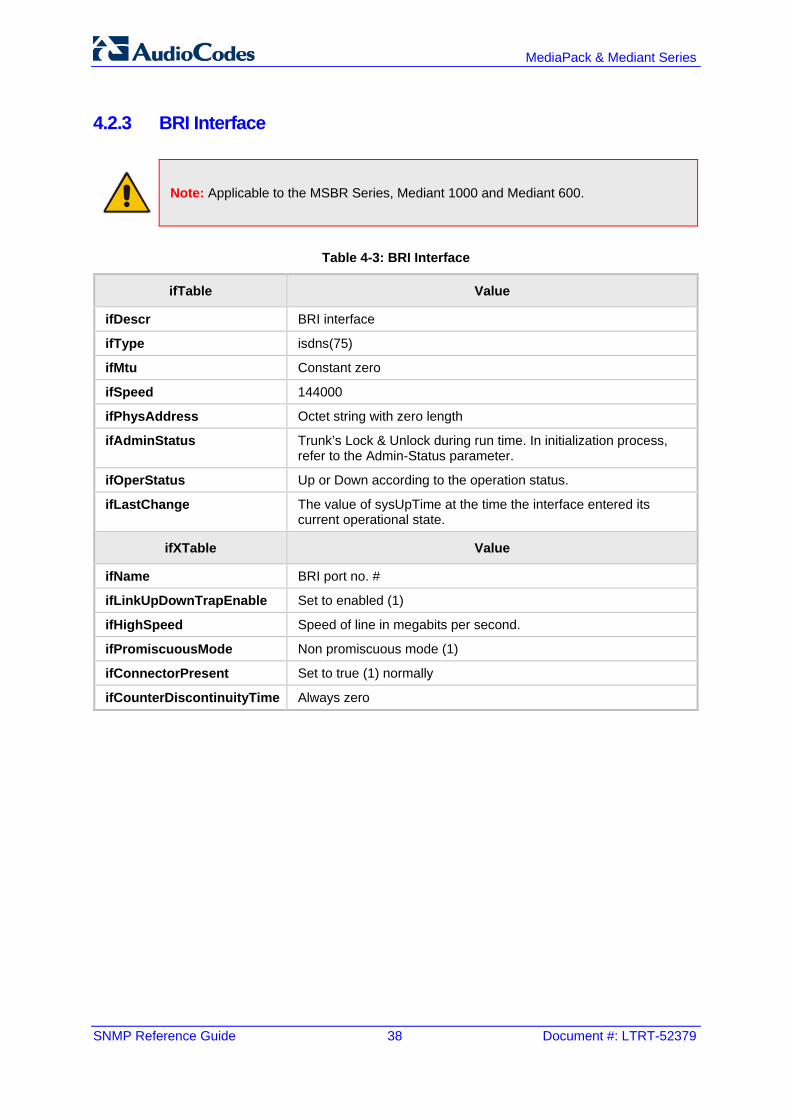
MediaPack & Mediant Series
SNMP Reference Guide 38 Document #: LTRT-52379
4.2.3 BRI Interface
Note: Applicable to the MSBR Series, Mediant 1000 and Mediant 600.
Table 4-3: BRI Interface
ifTable Value
ifDescr BRI interface
ifType isdns(75)
ifMtu Constant zero
ifSpeed 144000
ifPhysAddress Octet string with zero length
ifAdminStatus Trunk’s Lock & Unlock during run time. In initialization process, refer to the Admin-Status parameter.
ifOperStatus Up or Down according to the operation status.
ifLastChange The value of sysUpTime at the time the interface entered its current operational state.
ifXTable Value
ifName BRI port no. #
ifLinkUpDownTrapEnable Set to enabled (1)
ifHighSpeed Speed of line in megabits per second.
ifPromiscuousMode Non promiscuous mode (1)
ifConnectorPresent Set to true (1) normally
ifCounterDiscontinuityTime Always zero

SNMP Reference Guide 4. Topology MIB Objects
Version 6.8 39 MediaPack & Mediant Series
4.2.4 ADSL/VDSL Interface
Note: Applicable to the Mediant 500 MSBR and Mediant 800B MSBR.
Table 4-4: ADSL/VDSL Interface
ifTable & ifXTable Value
ifInOctets The number of octets in valid MAC frames received on this interface, including the MAC header and FCS. Includes the number of octets in valid MAC Control frames received on this interface.
ifInUcastPkts As defined in IfMIB.
ifInDiscards As defined in IfMIB.
ifInErrors The sum for this interface of dot3StatsAlignmentErrors, dot3StatsFCSErrors, dot3StatsFrameTooLongs, and dot3StatsInternalMacReceiveErrors.
ifInUnknownProtos As defined in IfMIB.
ifOutOctets The number of octets transmitted in valid MAC frames on this interface, including the MAC header and FCS. This does include the number of octets in valid MAC Control frames transmitted on this interface.
ifOutUcastPkts As defined in IfMIB.
ifOutDiscards As defined in IfMIB.
ifOutErrors The sum for this interface of: dot3StatsSQETestErrors, dot3StatsLateCollisions, dot3StatsExcessiveCollisions, dot3StatsInternalMacTransmitErrors and dot3StatsCarrierSenseErrors.

MediaPack & Mediant Series
SNMP Reference Guide 40 Document #: LTRT-52379
4.2.5 DS3 Interface
Note: Applicable only to the Mediant 3000.
Table 4-5: DS3 Interface
ifTable & ifXTable Value
ifDescr DS3 interface, Module no.#d, Port no.#d
ifType Ds3(30).
ifMtu Constant zero.
ifSpeed 44736000
ifPhysAddress The value of the Circuit Identifier. If no Circuit Identifier has been assigned this object should have an octet string with zero length.
ifAdminStatus Read-only access -- Always UP.
ifOperStatus The value testing(3) is not used. This object assumes the value down(2), if the objects dsx3LineStatus has any other value than dsx3NoAlarm(1).
ifLastChange The value of sysUpTime at the time the interface entered its current operational state.
ifName DS3 port no. n
ifLinkUpDownTrapEnable Set to enabled(1)
ifHighSpeed Speed of line in Megabits per second: 45
ifConnectorPresent Set to true(1)
ifCounterDiscontinuityTime Always zero.
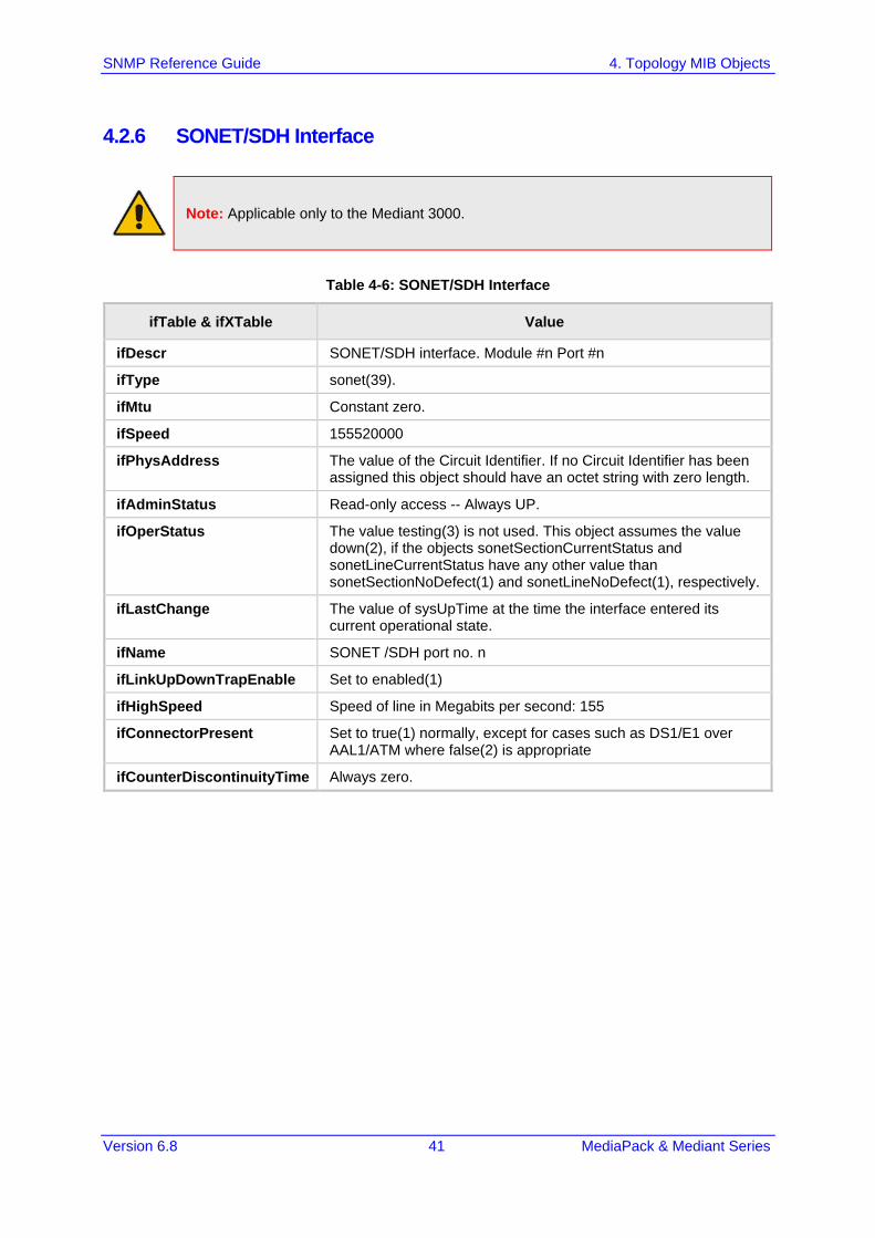
SNMP Reference Guide 4. Topology MIB Objects
Version 6.8 41 MediaPack & Mediant Series
4.2.6 SONET/SDH Interface
Note: Applicable only to the Mediant 3000.
Table 4-6: SONET/SDH Interface
ifTable & ifXTable Value
ifDescr SONET/SDH interface. Module #n Port #n
ifType sonet(39).
ifMtu Constant zero.
ifSpeed 155520000
ifPhysAddress The value of the Circuit Identifier. If no Circuit Identifier has been assigned this object should have an octet string with zero length.
ifAdminStatus Read-only access -- Always UP.
ifOperStatus The value testing(3) is not used. This object assumes the value down(2), if the objects sonetSectionCurrentStatus and sonetLineCurrentStatus have any other value than sonetSectionNoDefect(1) and sonetLineNoDefect(1), respectively.
ifLastChange The value of sysUpTime at the time the interface entered its current operational state.
ifName SONET /SDH port no. n
ifLinkUpDownTrapEnable Set to enabled(1)
ifHighSpeed Speed of line in Megabits per second: 155
ifConnectorPresent Set to true(1) normally, except for cases such as DS1/E1 over AAL1/ATM where false(2) is appropriate
ifCounterDiscontinuityTime Always zero.

MediaPack & Mediant Series
SNMP Reference Guide 42 Document #: LTRT-52379
4.2.7 VLAN Interface
Note: Applicable only to the MSBR Series.
Table 4-7: VLAN Interface
ifTable Value
ifDescr CLI interface name. If not exists - Virtual LAN Interface / WAN Virtual LAN Interface
ifType ds1(136).
ifMtu Interface MTU [default 1500]
ifSpeed 0
ifPhysAddress The value of the Circuit Identifier [dsx1CircuitIdentifier]. If no Circuit Identifier has been assigned this object should have an octet string with zero length.
ifAdminStatus INTERFACE_STATUS_WORKING -> snmpIF_ifAdminStatus_up_E/snmpIF_ifOperStatus_up_E INTERFACE_STATUS_UNKNOWN) INTERFACE_STATUS_DISABLED INTERFACE_STATUS_INACTIVE -> snmpIF_ifAdminStatus_down_E/snmpIF_ifOperStatus_down_E
ifOperStatus
ifLastChange The value of sysUpTime at the time the interface entered its current operational state.
ifXTable Value
ifName Interface name
ifLinkUpDownTrapEnable Set to enabled(1)
ifHighSpeed Speed of line in Megabits per second: 2
ifConnectorPresent Set to true(1) normally
ifCounterDiscontinuityTime Always zero.

SNMP Reference Guide 4. Topology MIB Objects
Version 6.8 43 MediaPack & Mediant Series
4.3 MIB-II Counters
Note: Applicable only to the MSBR Series.
TCP (1.3.6.1.2.1.6):
• tcpRtoAlgorithm • tcpRtoMin • tcpRtoMax • tcpMaxConn • tcpActiveOpens • tcpPassiveOpens • tcpAttemptFails • tcpEstabResets • tcpCurrEstab • tcpInSegs • tcpOutSegs • tcpRetransSegs • tcpInErrs • tcpOutRsts • tcpHCInSegs • tcpHCOutSegs
UDP (1.3.6.1.2.1.7): • udpInDatagrams • udpNoPorts • udpInErrors • udpOutDatagrams • udpHCInDatagrams • udpHCOutDatagrams
IP (1.3.6.1.2.1.4): • ipForwarding • ipDefaultTTL • ipInReceives • ipInHdrErrors • ipInAddrErrors • ipForwDatagrams • ipInUnknownProtos • ipInDiscards • ipInDelivers • ipOutRequests • ipOutDiscards • ipOutNoRoutes

MediaPack & Mediant Series
SNMP Reference Guide 44 Document #: LTRT-52379
• ipReasmTimeout • ipReasmReqds • ipReasmOKs • ipReasmFails • ipFragCreate
ICMP (1.3.6.1.2.1.5): • icmpInMsgs • icmpInErrors • icmpInDestUnreachs • icmpInTimeExcds • icmpInParmProbs • icmpInSrcQuenchs • icmpInRedirects • icmpInEchos • icmpInEchoReps • icmpInTimestamps • icmpInTimestampReps • icmpInAddrMasks • icmpInAddrMaskReps • icmpOutMsgs • icmpOutErrors • icmpOutDestUnreachs • icmpOutTimeExcds • icmpOutParmProbs • icmpOutSrcQuenchs • icmpOutRedirects • icmpOutEchos • icmpOutEchoReps • icmpOutTimestamps • icmpOutTimestampReps • icmpOutAddrMasks • icmpOutAddrMaskReps
IF (1.3.6.1.2.1.2.2): • ifInOctets • ifInUcastPkts • ifInDiscards • ifInErrors • ifOutOctets • ifOutUcastPkts • ifOutErrors • ifInMulticastPkts • ifInBroadcastPkts • ifOutMulticastPkts • ifOutBroadcastPkts

SNMP Reference Guide 5. File Management
Version 6.8 45 MediaPack & Mediant Series
5 File Management SNMP supports file download, upload, and removal.
5.1 Downloading a File to the Device The file URL is set in the appropriate MIB object under the acSysHTTPClient subtree (refer to the subtree objects description for the URL form). The download can be scheduled using the acSysHTTPClientAutoUpdatePredefinedTime and acSysHTTPClientAutoUpdateFrequency objects. It can also be a manual process using acSysActionSetAutoUpdate. In this case (only) and as long as one URL is set at a time, the result can be viewed in acSysActionSetAutoUpdateActionResult. In both cases, the acHTTPDownloadResult trap is sent, indicating the success or failure of the process. acSysActionSetActionId can be set to any value and can be used to indicate an action performed by a certain manager. A successful process also ends with the file name in the appropriate object under the acSysFile subtree or in the acCASFileTable or the acAuxiliaryFiles subtree, along with the URL being erased from the object under the acSysHTTPClient subtree.
Notes:
• The action result (both in the acSysActionSetAutoUpdateActionResult object and acHTTPDownloadResult trap) for the Voice Prompt and XML indicates only that the file reached the device and has no indication on the application’s ability to parse the file.
• The action result in acSysActionSetAutoUpdateActionResult is reliable as long as only one file is downloaded at a time.
5.2 Uploading and Deleting a File File upload is the procedure of sending a file from the device to the manager. Deleting a file is erasing it from the device, an offline action that requires a reset for it to be applied. The acSysUpload subtree holds all relevant objects. acSysUploadFileURI indicates the file name and location along with the file transfer
protocol (HTTP/S), for example, “http:\\server\filename.txt”. acSysUploadFileType and acSysUploadFileNumber are used to determine the file
to be uploaded along with its instance when relevant (for CAS or Video Font). acSysUploadActionID is at the disposal of the manager and can be used to indicate
that a certain manager has performed the action. acSysUploadActionType determines the action that occurs and triggers it off at the
same time.
Note: File upload using SNMP is supported only for ini files; file removal using SNMP is supported for all files except ini files.

MediaPack & Mediant Series
SNMP Reference Guide 46 Document #: LTRT-52379
This page is intentionally left blank.

SNMP Reference Guide 6. Performance Measurements
Version 6.8 47 MediaPack & Mediant Series
6 Performance Measurements Performance measurements are available for a third-party performance monitoring system through an SNMP interface. These can be polled at scheduled intervals by an external poller or utility in the management server or other off-board systems. The device provides performance measurements in the form of two types: Gauges: Gauges represent the current state of activities on the device. Gauges unlike
counters can decrease in value and like counters, can increase. The value of a gauge is the current value or a snapshot of the current activity on the device at that moment.
Counters: Counters always increase in value and are cumulative. Counters, unlike gauges, never decrease in value unless the server is reset and then the counters are zeroed.
The device performance measurements are provided by several proprietary MIBs (located under the acPerformance subtree): iso(1).org(3).dod(6).internet(1).private(4).enterprises(1).AudioCodes(5003).acPerformance(10). The performance monitoring MIBs all have an identical structure, which includes two major subtrees: Configuration: allows configuration of general attributes of the MIB and specific
attributes of the monitored objects Data The monitoring results are presented in tables. There are one or two indices in each table. If there are two indices, the first is a sub-set in the table (e.g., trunk number) and the second (or a single where there is only one) index represents the interval number (present - 0, previous - 1, and the one before - 2). The MIBs include: acPMMedia: media-related (voice) monitoring such as RTP and DSP. acPMControl: Control Protocol-related monitoring such as connections, commands. acPMAnalog: Analog channels off-hook state. (Applicable only to Analog Series.) acPMPSTN: PSTN-related monitoring such as channel use, trunk utilization.
(Applicable only to Digital Series.) acPMSystem: general (system-related) monitoring. acPMMediaServer: for Media Server specific monitoring (applicable only to Mediant
3000). The log trap acPerformanceMonitoringThresholdCrossing (non-alarm) is sent every time the threshold of a Performance Monitored object is crossed. The severity field is 'indeterminate' when the crossing is above the threshold and 'cleared' when it goes back under the threshold. The 'source' varbind in the trap indicates the object for which the threshold is being crossed.

MediaPack & Mediant Series
SNMP Reference Guide 48 Document #: LTRT-52379
6.1 Total Counters The counter’s attribute 'total' accumulates counter values since the device's most recent restart. The user can reset the total’s value by setting the Reset-Total object. Each MIB module has its own Reset Total object, as follows: PM-Analog: acPMAnalogConfigurationResetTotalCounters (Applicable only to Analog
Series) PM-Control: acPMControlConfigurationResetTotalCounters PM-Media: acPMMediaConfigurationResetTotalCounters PM-PSTN: acPMPSTNConfigurationResetTotalCounters (Applicable only to Digital
Series) PM-System: acPMSystemConfigurationResetTotalCounters
6.2 SNMP Performance Monitoring MIBs The following sections show the performance monitoring SNMP MIBs.
Note: The tables in this section use check marks "√" and crosses "x" to indicate whether the MIB property is supported or not supported, respectively.

SNMP Reference Guide 6. Performance Measurements
Version 6.8 49 MediaPack & Mediant Series
6.2.1 IP Network Interface The SNMP MIBs below provide performance monitoring for the IP network interface.
Table 6-1: Performance Monitoring MIBS for IP Network Interface
Performance Monitoring MIB
Properties (Objects)
Gauge (G
) / Counter (C
)
Reporting Interval
Val
Min
Max
Avg
TimeB
elowLow
Threshold
TimeB
etweenThresholds
TimeA
boveHighThreshold
HighThreshold (D
efault)
LowThreshold (D
efault)
acPMNetUtilKBytesTable
Indicates the number of Kbytes (1000 bytes) received and transmitted on the interface (Index 0 is transmit; Index 1 is receive), including those received in error, from the beginning of the current collection interval as indicated by the time interval. EMS parameter name: Number of Incoming / Outgoing Kbytes High threshold:
acPMNetUtilsAttributesKBytesHighThreshold (1.3.6.1.4.1.5003.10.11.1.33.1)
Low threshold: acPMNetUtilsAttributesKBytesLowThreshold (1.3.6.1.4.1.5003.10.11.1.33.2)
G 15
acPMNetUtilPacketsTable
Indicates the number of incoming and outgoing packets from the interface (Index 0 is transmit; Index 1 is receive), from the beginning of the current collection interval as indicated by time Interval. EMS parameter name: Number of Outgoing / Incoming Pkts. High threshold:
acPMNetUtilsAttributesPacketsHighThreshold (1.3.6.1.4.1.5003.10.11.1.33.3)
Low threshold: acPMNetUtilsAttributesPacketsLowThreshold (1.3.6.1.4.1.5003.10.11.1.33.4)
G 15
acPMNetUtilDiscardedPacketsTable
Indicates the number of malformed IP packets received on the interface during the last interval. These are packets which are corrupted or discarded due to errors in their IP headers, including bad checksums, version number mismatch, other format errors, time-to-live exceeded, errors discovered in processing their IP options, etc. EMS parameter name: Number of Incoming Discarded Pkts.
C 15

MediaPack & Mediant Series
SNMP Reference Guide 50 Document #: LTRT-52379
6.2.2 Media Realms The SNMP MIBs below provide performance monitoring statistics for media realms.
Table 6-2: Performance Monitoring MIBS for Media Realms
Performance Monitoring MIB
Properties (Objects)
Gauge (G
) / Counter (C
)
Reporting Interval
Val
Min
Max
Avg
TimeB
elowLow
Threshold
TimeB
etweenThresholds
TimeA
boveHighThreshold
HighThreshold (D
efault)
LowThreshold (D
efault)
AcPMMediaRealmPacketLossRxTable
Indicates the received RTP packet loss (reported by RTCP) per Media Realm.
G 15 50 30
AcPMMediaRealmPacketLossTxTable
Indicates the transmitted RTP packet loss (reported by RTCP) per Media Realm.
G 15 50 30
AcPMMediaRealmBytesTxTable
Indicates the number of bytes received in RTCP data, per Media Realm. High threshold:
acPMMediaRealmAttributesMediaRealmBytesTxHighThreshold (1.3.6.1.4.1.5003.10.8.1.35.1)
Low threshold: acPMMediaRealmAttributesMediaRealmBytesTxLowThreshold (1.3.6.1.4.1.5003.10.8.1.35.2)
G 15 1500000 1000000
AcPMMediaRealmBytesRxTable
Indicates the number of bytes received in RTCP data, per Media Realm. High threshold:
acPMMediaRealmAttributesMediaRealmBytesRxHighThreshold (1.3.6.1.4.1.5003.10.8.1.35.3)
Low threshold: acPMMediaRealmAttributesMediaRealmBytesRxLowThreshold (1.3.6.1.4.1.5003.10.8.1.35.4)
G 15 1500000 1000000
acPMMediaRealmPacketsTxTable
Indicates the number of media packets sent in RTCP data, per Media Realm. High threshold:
acPMMediaRealmAttributesMediaRealmPacketsTxHighThreshold (1.3.6.1.4.1.5003.10.8.1.35.5)
Low threshold: acPMMediaRealmAttributesMediaRealmPacketsTxLowThreshold (1.3.6.1.4.1.5003.10.8.1.35.6)
G 15 7500 6000
acPMMediaRealmPacketsRxTable
Indicates the number of media packets received in RTCP data, per Media Realm. High threshold:
acPMMediaRealmAttributesMediaRealmPacketsRxHighThreshold (1.3.6.1.4.1.5003.10.8.1.35.7)
Low threshold: acPMMediaRealmAttributesMediaRealmPacketsRxLowThreshold (1.3.6.1.4.1.5003.10.8.1.35.8)
G 15 7500 6000
AcPMMediaRealmVERealmPacketDelayTable

SNMP Reference Guide 6. Performance Measurements
Version 6.8 51 MediaPack & Mediant Series
Performance Monitoring MIB
Properties (Objects)
Gauge (G
) / Counter (C
)
Reporting Interval
Val
Min
Max
Avg
TimeB
elowLow
Threshold
TimeB
etweenThresholds
TimeA
boveHighThreshold
HighThreshold (D
efault)
LowThreshold (D
efault)
Indicates the packet delay in RTCP data, per Media Realm. High threshold:
acPMMediaRealmAttributesVERealmPacketDelayHighThreshold (1.3.6.1.4.1.5003.10.8.1.35.9)
Low threshold: acPMMediaRealmAttributesVERealmPacketDelayLowThreshold (1.3.6.1.4.1.5003.10.8.1.35.10)
G 15 150 120
AcPMMediaRealmVERealmPacketJitterTable
Indicates the packet jitter in RTCP data, per Media Realm. High threshold:
acPMMediaRealmAttributesVERealmPacketJitterHighThreshold (1.3.6.1.4.1.5003.10.8.1.35.11)
Low threshold: acPMMediaRealmAttributesVERealmPacketJitterLowThreshold (1.3.6.1.4.1.5003.10.8.1.35.12)
G 15 150 120
acPMMediaRealmRealmMOSTable
Indicates the MOS quality in RTCP-XR data, per Media Realm. High threshold:
acPMMediaRealmAttributesRealmMOSHighThreshold (1.3.6.1.4.1.5003.10.8.1.35.13)
Low threshold: acPMMediaRealmAttributesRealmMOSLowThreshold (1.3.6.1.4.1.5003.10.8.1.35.14)
G 15 50 10
acPMMediaRealmBwRxTable
Indicates the average bandwidth for Rx bytes, per Media Realm. High threshold:
acPMMediaRealmAttributesMediaRealmBwRxHighThreshold (1.3.6.1.4.1.5003.10.8.1.35.15)
Low threshold: acPMMediaRealmAttributesMediaRealmBwRxLowThreshold (1.3.6.1.4.1.5003.10.8.1.35.16)
G 15 1500000 0
acPMMediaRealmBwTxTable
Indicates the average bandwidth for Tx bytes, per Media Realm. High threshold:
acPMMediaRealmAttributesMediaRealmBwTxHighThreshold (1.3.6.1.4.1.5003.10.8.1.35.17)
Low threshold: acPMMediaRealmAttributesMediaRealmBwTxLowThreshold (1.3.6.1.4.1.5003.10.8.1.35.18)
G 15 1500000 0

MediaPack & Mediant Series
SNMP Reference Guide 52 Document #: LTRT-52379
6.2.3 VoIP Calls The SNMP MIBs below provide performance monitoring statistics for VoIP calls.
Note: These MIBs are not applicable to the MediaPack Series.
Table 6-3: Performance Monitoring MIBS for VoIP Calls
Performance Monitoring MIB
Properties (Objects)
Gauge (G
) / Counter (C
)
Reporting Interval
Val
Min
Max
Avg
TimeB
elowLow
Threshold
TimeB
etweenThresholds
TimeA
boveHighThreshold
HighThreshold
LowThreshold
acPMChannelsPerCoderTable
Indicates the number of active channels per coder, where Index denotes the coder (Index: 0=G711, 1=G723, 2=G728, 3=G729a, 4=G729e, 5=AMR etc.). High threshold:
acPMCodersAttributesChannelsPerCoderHighThreshold (1.3.6.1.4.1.5003.10.7.1.32.1)
Low threshold: acPMCodersAttributesChannelsPerCoderLowThreshold (1.3.6.1.4.1.5003.10.7.1.32.2)
G 15
acPMModuleRTPPacketLossRxTable
Indicates the Rx RTP packet loss (reported by RTCP), during the time Interval. EMS parameter name: Rx RTP Packet Loss. High threshold:
acPMNetworkingAttributesModuleRTPPacketLossRxHighThreshold (1.3.6.1.4.1.5003.10.7.1.33.17)
Low threshold: acPMNetworkingAttributesModuleRTPPacketLossRxLowThreshold (1.3.6.1.4.1.5003.10.7.1.33.18)
G 15
acPMModuleRTPPacketLossTxTable
Indicates the Tx RTP packet loss (reported by RTCP), during the time Interval. EMS parameter name: Tx RTP Packet Loss. High threshold:
acPMNetworkingAttributesModuleRTPPacketLossTxHighThreshold (1.3.6.1.4.1.5003.10.7.1.33.19)
Low threshold: acPMNetworkingAttributesModuleRTPPacketLossTxLowThreshold (1.3.6.1.4.1.5003.10.7.1.33.20)
G 15
acPMModulePacketDelayTable

SNMP Reference Guide 6. Performance Measurements
Version 6.8 53 MediaPack & Mediant Series
Performance Monitoring MIB
Properties (Objects)
Gauge (G
) / Counter (C
)
Reporting Interval
Val
Min
Max
Avg
TimeB
elowLow
Threshold
TimeB
etweenThresholds
TimeA
boveHighThreshold
HighThreshold
LowThreshold
Indicates the RTP packet delay during the collection time interval. EMS parameter name: RTP delay. High threshold:
acPMNetworkingAttributesPacketDelayHighThreshold (1.3.6.1.4.1.5003.10.7.1.33.1)
Low threshold: acPMNetworkingAttributesPacketDelayLowThreshold (1.3.6.1.4.1.5003.10.7.1.33.2)
G 15
acPMModulePacketJitterTable
Indicates the RTP packet jitter during the collection time interval. EMS parameter name: RTP jitter. High threshold:
acPMNetworkingAttributesPacketJitterHighThreshold (1.3.6.1.4.1.5003.10.7.1.33.3)
Low threshold: acPMNetworkingAttributesPacketJitterLowThreshold (1.3.6.1.4.1.5003.10.7.1.33.4)
G 15
acPMModuleRTPBytesRxTable
Indicates the Tx RTP bytes during the collection time interval. EMS parameter name: Rx RTP Bytes. High threshold:
acPMNetworkingAttributesRTPBytesRxHighThreshold (1.3.6.1.4.1.5003.10.7.1.33.7)
Low threshold: acPMNetworkingAttributesRTPBytesRxLowThreshold (1.3.6.1.4.1.5003.10.7.1.33.8)
G 15
acPMModuleRTPBytesTxTable
Indicates the Rx RTP bytes during the collection time interval. EMS parameter name: Tx RTP Bytes. High threshold:
acPMNetworkingAttributesRTPBytesTxHighThreshold (1.3.6.1.4.1.5003.10.7.1.33.5)
Low threshold: acPMNetworkingAttributesRTPBytesTxLowThreshold (1.3.6.1.4.1.5003.10.7.1.33.6)
G 15
acPMModuleRTPPacketsRxTable
Indicates the Rx RTP packets during the collection time interval. EMS parameter name: Rx RTP Packets. High threshold:
acPMNetworkingAttributesRTPPacketsRxHighThreshold (1.3.6.1.4.1.5003.10.7.1.33.11)
Low threshold: acPMNetworkingAttributesRTPPacketsRxLowThreshold (1.3.6.1.4.1.5003.10.7.1.33.12)
G 15
acPMModuleRTPPacketsTxTable

MediaPack & Mediant Series
SNMP Reference Guide 54 Document #: LTRT-52379
Performance Monitoring MIB
Properties (Objects)
Gauge (G
) / Counter (C
)
Reporting Interval
Val
Min
Max
Avg
TimeB
elowLow
Threshold
TimeB
etweenThresholds
TimeA
boveHighThreshold
HighThreshold
LowThreshold
Indicates the Tx RTP Packets during the collection time interval. EMS parameter name: Tx RTP Packets. High threshold:
acPMNetworkingAttributesRTPPacketsTxHighThreshold (1.3.6.1.4.1.5003.10.7.1.33.9)
Low threshold: acPMNetworkingAttributesRTPPacketsTxLowThreshold (1.3.6.1.4.1.5003.10.7.1.33.10)
G 15
6.2.4 SIP IP-to-Tel and Tel-to-IP Calls The SNMP MIBs below provide performance monitoring for SIP IP-to-Tel and Tel-to-IP calls.
Note: In MIB tables, Index 0 indicates Tel-to-IP calls and Index 1 indicates IP-to-Tel calls.
Table 6-4: Performance Monitoring MIBs for SIP IP-to-Tel and Tel-to-IP Calls
Performance Monitoring MIB
Properties (Objects)
Gauge (G
) / Counter (C
)
Reporting Interval
Val
Min
Max
Avg
TimeB
elowLow
Threshold
TimeB
etweenThresholds
TimeA
boveHighThreshold
HighThreshold
LowThreshold
acPMSIPAttemptedCallsTable
Indicates the number of attempted calls (Index 1) during last interval. EMS parameter name: IP to Tel / Tel to IP Number of Call Attempts
C 15
acPMSIPCallDurationTable

SNMP Reference Guide 6. Performance Measurements
Version 6.8 55 MediaPack & Mediant Series
Performance Monitoring MIB
Properties (Objects)
Gauge (G
) / Counter (C
)
Reporting Interval
Val
Min
Max
Avg
TimeB
elowLow
Threshold
TimeB
etweenThresholds
TimeA
boveHighThreshold
HighThreshold
LowThreshold
Indicates the call duration of established calls during last interval. EMS parameter name: IP to Tel / Tel to IP Average Call Duration [sec]calls. High threshold:
acPMSipAttributesCallDurationHighThreshold (1.3.6.1.4.1.5003.10.8.1.34.1)
Low threshold: acPMSipAttributesCallDurationLowThreshold (1.3.6.1.4.1.5003.10.8.1.34.2)
G/ C 15
acPMSIPNoMatchCallsTable
Indicates the number of calls that failed due to mismatched media server capabilities for calls, during last interval. EMS parameter name: IP to Tel / Tel to IP Number of Failed Calls due to No Matched Capabilities.
C 15
acPMSIPBusyCallsTable
Indicates the number of calls that failed as a result of a busy line, during last interval. EMS parameter name: IP to Tel / Tel to IP Number of Calls Terminated due to a Busy Line.
C 15
acPMSIPNoAnswerCallsTable
Indicates the number of calls that weren't answered during last interval. EMS parameter name: IP to Tel / Tel to IP Number of Calls Terminated due to No Answer.
C 15
acPMSIPNoRouteCallsTable
Indicates the number of calls whose destinations weren't found during last interval. EMS parameter name: IP to Tel / Tel to IP Number of Failed Calls due to No Route.
C 15
acPMSIPFailCallsTable
This counter is incremented as a result of calls that fail due to reasons not covered by the other counters during last interval. EMS parameter name: IP to Tel / Tel to IP Number of Failed Calls due to Other reasons.
C 15
acPMSIPEstablishedCallsTable
Indicates the number of established calls during last interval. EMS parameter name: IP to Tel / Tel to IP Number of Established Calls.
C 15
acPMSIPFaxAttemptedCallsTable
Indicates the number of attempted fax calls. C 15
acPMSIPFaxSuccessCallsTable
Indicates the number of successfully established fax calls. C 15

MediaPack & Mediant Series
SNMP Reference Guide 56 Document #: LTRT-52379
Performance Monitoring MIB
Properties (Objects)
Gauge (G
) / Counter (C
)
Reporting Interval
Val
Min
Max
Avg
TimeB
elowLow
Threshold
TimeB
etweenThresholds
TimeA
boveHighThreshold
HighThreshold
LowThreshold
acPMSIPForwardedCallsEntry
Indicates the number of calls that were terminated due to a call forward during last interval. EMS parameter name: IP to Tel / Tel to IP Number of Calls Terminated due to Forward.
C 15
acPMSIPNoResourcesCallsTable
Indicates the number of calls that failed due to unavailable resources or a media server lock during last interval. EMS parameter name: IP to Tel / Tel to IP Number of Failed Calls due to No Resources.
C 15
acPMSIPTel2IPTrunkEstablishedCallsTable
Indicates the current number of established calls pertaining to a trunk for Tel-to-IP calls.
G 15
acPMSIPIP2TelTrunkEstablishedCallsTable
Indicates the current number of established calls pertaining to a trunk for IP-to-Tel calls.
G 15
acPMSIPTel2IPTrunkGroupEstablishedCallsTable
Indicates the current number of established calls pertaining to a Trunk Group for Tel-to-IP calls.
G 15
acPMSIPIP2TelTrunkGroupEstablishedCallsTable
Indicates the current number of established calls pertaining to a Trunk Group for IP-to-Tel calls.
G 15

SNMP Reference Guide 6. Performance Measurements
Version 6.8 57 MediaPack & Mediant Series
6.2.5 DS3 The SNMP MIBs below enable performance monitoring for DS3.
Note: These MIBs apply only to Mediant 3000 featuring the TP-6310 blade.
Table 6-5: Performance Monitoring MIBS for DS3
Performance Monitoring MIB
Properties (Objects)
Gauge (G
) / Counter (C
)
Reporting Interval
Val
Min
Max
Avg
TimeB
elowLow
Threshold
TimeB
etweenThresholds
TimeA
boveHighThreshold
HighThreshold
LowThreshold
dsx3IntervalTable
The DS3/E3 Interval Table contains various statistics collected by each DS3/E3 Interface over the previous 24 hours of operation. The past 24 hours are broken into 96 completed 15 minute intervals. Each row in this table represents one such interval (identified by dsx3IntervalNumber) and for one specific interface (identified by dsx3IntervalIndex). dsx3IntervalPESs: number of P-bit Errored Seconds (EMS
parameter name: DS3 PESs) dsx3IntervalPSESs: number of P-bit Severely Errored Seconds
(EMS parameter name: DS3 PSESs) dsx3IntervalUASs: number of Unavailable Seconds. This object
may decrease if the occurrence of unavailable seconds occurs across an interval boundary (EMS parameter name: DS3 UASs)
dsx3IntervalLCVs: number of Line Coding Violations (EMS parameter name: DS3 LCVs)
dsx3IntervalLESs: number of P-bit Coding Violations (EMS parameter name: dsx3IntervalPCVs)
dsx3IntervalCCVs: number of Line Errored Seconds - BPVs or illegal zero sequences (EMS parameter name: DS3 LESs)
dsx3IntervalCESs: number of C-bit Errored Seconds (EMS parameter name: DS3 CESs)
dsx3IntervalCSESs: number of C-bit Severely Errored Seconds (EMS parameter name: DS3 CSESs)
dsx3CurrentPESs: number of P-bit Errored Seconds dsx3CurrentPSESs: number of P-bit Severely Errored Seconds dsx3CurrentUASs: number of Unavailable Seconds dsx3CurrentLCVs: number of Line Coding Violations dsx3CurrentPCVs: number of P-bit Coding Violations dsx3CurrentLESs: number of Line Errored Seconds dsx3CurrentCCVs: number of C-bit Coding Violations dsx3CurrentCESs: number of C-bit Errored Seconds dsx3CurrentCSESs: number of C-bit Severely Errored Seconds
G 15

MediaPack & Mediant Series
SNMP Reference Guide 58 Document #: LTRT-52379
6.2.6 Fiber Group The SNMP MIBs below provide performance monitoring for the Fiber Group.
Note: These MIBs apply only to Mediant 3000 featuring the TP-6310 blade.
Table 6-6: Performance Monitoring MIBS for Fiber Group
Performance Monitoring MIB
Properties (Objects)
Gauge (G
) / Counter (C
)
Reporting Interval
Val
Min
Max
Avg
TimeB
elowLow
Threshold
TimeB
etweenThresholds
TimeA
boveHighThreshold
HighThreshold
LowThreshold
sonetSectionCurrentTable
SONET/SDH Section Current table. sonetSectionCurrentESs: number of Errored Seconds
encountered by a SONET/SDH Section in the current 15 minute interval (EMS parameter name: Section ESs)
sonetSectionCurrentSESs: number of Severely Errored Seconds encountered by a SONET/SDH Section in the current 15 minute interval (EMS parameter name: Section SESs)
sonetSectionCurrentCVs: number of Coding Violations encountered by a SONET/SDH Section in the current 15 minute interval (EMS parameter name: Section CVs)
G 15
sonetLineCurrentTable
SONET/SDH Line Current table. SonetLineCurrentESs: number of Errored Seconds
encountered by a SONET/SDH Line in the current 15 minute interval (EMS parameter name: Line ESs)
SonetLineCurrentSESs: number of Severely Errored Seconds encountered by a SONET/SDH Line in the current 15 minute interval (EMS parameter name: Line SESs)
SonetLineCurrentCVs: number of Coding Violations encountered by a SONET/SDH Line in the current 15 minute interval (EMS parameter name: Line CVs)
SonetLineCurrentUASs: number of Unavailable Seconds encountered by a SONET/SDH Line in the current 15 minute interval (EMS parameter name: Line UASs)
G 15
sonetPathCurrentTable
SONET/SDH Path Current table. SonetPathCurrentESs: number of Errored Seconds
encountered by a SONET/SDH Path in the current 15 minute interval (EMS parameter name: Path ESs)
SonetPathCurrentSESs: number of Severely Errored Seconds encountered by a SONET/SDH Path in the current 15 minute interval (EMS parameter name: Path SESs)
SonetPathCurrentCVs: number of Coding Violations encountered by a SONET/SDH Path in the current 15 minute interval (EMS parameter name: Path CVs)
SonetPathCurrentUASs: number of Unavailable Seconds encountered by a Path in the current 15 minute interval (EMS parameter name: Path UASs)
G 15

SNMP Reference Guide 6. Performance Measurements
Version 6.8 59 MediaPack & Mediant Series
6.2.7 High Availability The SNMP MIBs below provide performance monitoring for High Availability (HA) mode.
Table 6-7: Performance Monitoring MIBS for High-Availability
Performance Monitoring MIB
Properties (Objects)
Gauge (G
) / Counter (C
)
Reporting Interval
Val
Min
Max
Avg
TimeB
elowLow
Threshold
TimeB
etweenThresholds
TimeA
boveHighThreshold
HighThreshold (D
efault)
LowThreshold (D
efault)
AcPMHALinkRedundantToActivePacketLossPercentageTable
Indicates packet loss (in %) on the HA Maintenance interface from Redundant to Active device, where 0% indicates no packet loss. High threshold:
acPMHAAttributesHALinkRedundantToActivePacketLossPercentageHighThreshold (1.3.6.1.4.1.5003.10.11.1.38.1)
Low threshold: acPMHAAttributesHALinkRedundantToActivePacketLossPercentageLowThreshold (1.3.6.1.4.1.5003.10.11.1.38.2)
G 15 (30)
5
AcPMHALinkActiveToRedundantPacketLossPercentageTable
Indicates packet loss (in %) on the HA Maintenance interface from Active to Redundant device, where 0% indicates no packet loss. High threshold:
acPMHAAttributesHALinkActiveToRedundantPacketLossPercentageHighThreshold (1.3.6.1.4.1.5003.10.11.1.38.3)
Low threshold: acPMHAAttributesHALinkActiveToRedundantPacketLossPercentageLowThreshold (1.3.6.1.4.1.5003.10.11.1.38.4)
G 15 30 5

MediaPack & Mediant Series
SNMP Reference Guide 60 Document #: LTRT-52379
6.2.8 SIP Messages The SNMP MIB below provides performance monitoring for SIP messages.
Table 6-8: Performance Monitoring MIBS for SIP Messages
Performance Monitoring MIB
Properties (Objects)
Gauge (G
) / Counter (C
)
Reporting Interval
Val
Min
Max
Avg
TimeB
elowLow
Threshold
TimeB
etweenThresholds
TimeA
boveHighThreshold
HighThreshold
LowThreshold
acPMSIPActiveSIPTransactionsPerSecondTable
Indicates the number of active incoming and outgoing SIP transactions (e.g., INVITE message) per second. High threshold:
acPMSipAttributesActiveSIPTransactionsPerSecondHighThreshold (1.3.6.1.4.1.5003.10.8.1.34.35)
Low threshold: acPMSipAttributesActiveSIPTransactionsPerSecondLowThreshold (1.3.6.1.4.1.5003.10.8.1.34.36)
G 15 0 0
acPMSIPIPGroupInviteDialogsTable
Indicates the number of INVITE dialogs per IP Group. High threshold:
acPMSipAttributesIPGroupINVITEDialogsHighThreshold (1.3.6.1.4.1.5003.10.8.1.34.25)
Low threshold: acPMSipAttributesIPGroupINVITEDialogsLowThreshold (1.3.6.1.4.1.5003.10.8.1.34.26)
G 15 0 0

SNMP Reference Guide 6. Performance Measurements
Version 6.8 61 MediaPack & Mediant Series
6.2.9 SBC Sessions The SNMP MIB below provides performance monitoring for SBC (Session Border Controllers) sessions.
Table 6-9: Performance Monitoring MIBS for SBC Sessions
Performance Monitoring MIB
Properties (Objects)
Gauge (G
) / Counter (C
)
Reporting Interval
Val
Min
Max
Avg
TimeB
elowLow
Threshold
TimeB
etweenThresholds
TimeA
boveHighThreshold
HighThreshold
LowThreshold
acPMSIPSBCAttemptedCallsTable
Indicates the number of attempted SBC calls. High threshold:
acPMSipAttributesSBCAttemptedCallsHighThreshold (1.3.6.1.4.1.5003.10.8.1.34.37)
Low threshold: acPMSipAttributesSBCAttemptedCallsLowThreshold (1.3.6.1.4.1.5003.10.8.1.34.38)
C 15 0 0
acPMSIPSBCEstablishedCallsTable
Indicate the number of established SBC calls. High threshold:
acPMSipAttributesSBCEstablishedCallsHighThreshold (1.3.6.1.4.1.5003.10.8.1.34.39)
Low threshold: acPMSipAttributesSBCEstablishedCallsLowThreshold (1.3.6.1.4.1.5003.10.8.1.34.40)
C 15 0 0
acPMSBCMediaLegsTable
Indicates the number of media (RTP) session resources currently utilized. High threshold: acPMSbcMediaLegsHighThreshold
(1.3.6.1.4.1.5003.10.8.1.36.50) Low threshold: acPMSbcMediaLegsLowThreshold
(1.3.6.1.4.1.5003.10.8.1.36.51)
G 15 0 0
acPMSBCTranscodingSessionsTable
Indicates the number of transcoding sessions. High threshold:
acPMSbcSBCTranscodingSessionsHighThreshold (1.3.6.1.4.1.5003.10.8.1.36.52)
Low threshold: acPMSbcSBCTranscodingSessionsLowThreshold (1.3.6.1.4.1.5003.10.8.1.36.53)
C 15

MediaPack & Mediant Series
SNMP Reference Guide 62 Document #: LTRT-52379
6.2.10 SBC Admission Control The SNMP MIBs below provide performance monitoring statistics for SBC Admission Control. Performance monitoring is performed per: SRD/IP Group Incoming, outgoing, or both SIP request types - INVITE, SUBSCRIBE, OTHER, or ALL Performance monitoring is provided by the acGateway MIB.
Note: This section applies only to the SBC Series.
Table 6-10: Performance Monitoring MIBS for SBC Call Admission
Performance Monitoring MIB
Properties (Objects) G
auge (G) / C
ounter (C)
Reporting Interval
Val
Min
Max
Avg
TimeB
elowLow
Threshold
TimeB
etweenThresholds
TimeA
boveHighThreshold
HighThreshold (D
efault)
LowThreshold (D
efault)
acPMSIPSRDDialogsTable
Indicates the number of all dialogs currently being handled by the SBC per SRD.
G 15
acPMSIPSRDInviteDialogsTable
Indicates the number of all calls (initiated by SIP:INVITE) currently being handled by the SBC per SRD.
G 15
acPMSIPSRDSubscribeDialogsTable
Indicates the number of all SUBSCRIBE dialogs (initiated by SIP:SUBSCRIBE) currently being handled by the SBC per SRD.
G 15
acPMSIPSRDOtherDialogsTable
Indicates the number of all dialogs other than INVITE and SUBSCRIBE (initiated by SIP:REGISTER) currently being handled by the SBC per SRD.
G 15
acPMSIPIPGroupDialogsTable
Indicates the number of all dialogs currently being handled by the SBC per IP Group.
G 15

SNMP Reference Guide 6. Performance Measurements
Version 6.8 63 MediaPack & Mediant Series
Performance Monitoring MIB
Properties (Objects)
Gauge (G
) / Counter (C
)
Reporting Interval
Val
Min
Max
Avg
TimeB
elowLow
Threshold
TimeB
etweenThresholds
TimeA
boveHighThreshold
HighThreshold (D
efault)
LowThreshold (D
efault)
acPMSIPIPGroupSubscribeDialogsTable
Indicates the number of all SUBSCRIBE dialogs (initiated by SIP:SUBSCRIBE) currently being handled by the SBC, per IP Group. High threshold:
acPMSipAttributesIPGroupSubscribeDialogsHighThreshold (1.3.6.1.4.1.5003.10.8.1.34.27)
Low threshold: acPMSipAttributesIPGroupSubscribeDialogsLowThreshold (1.3.6.1.4.1.5003.10.8.1.34.28)
G 15 0 0
acPMSIPIPGroupOtherDialogsTable
Indicates the number of all other dialogs other than INVITE and SUBSCRIBE (initiated by SIP:REGISTER) currently being handled by the SBC per IP Group.
G 15
acPMSIPIPGroupInOtherDialogsTable
Indicates the number of all incoming dialogs other than INVITE and SUBSCRIBE (initiated by SIP:REGISTER) currently being handled by the SBC per IP Group.
G 15
acPMSIPIPGroupOutOtherDialogsTable
Indicates the number of all outgoing dialogs other than INVITE and SUBSCRIBE (initiated by SIP:REGISTER) currently being handled by the SBC per IP Group.
G 15
acPMSIPIPGroupInInviteDialogsTable
Indicates the number of incoming calls (SIP INVITE) per IP Group. High threshold:
acPMSipAttributesIPGroupInInviteDialogsHighThreshold (1.3.6.1.4.1.5003.10.8.1.34.13)
Low threshold: acPMSipAttributesIPGroupInInviteDialogsLowThreshold (1.3.6.1.4.1.5003.10.8.1.34.14)
G 15 0 0
acPMSIPIPGroupInSubscribeDialogsTable
Indicates the number of incoming SUBSCRIBE dialogs per IP Group. High threshold:
acPMSipAttributesIPGroupInSubscribeDialogsHighThreshold (1.3.6.1.4.1.5003.10.8.1.34.15)
Low threshold: acPMSipAttributesIPGroupInSubscribeDialogsLowThreshold (1.3.6.1.4.1.5003.10.8.1.34.16)
G 15 0 0
acPMSIPIPGroupOutInviteDialogsTable
Indicates the number of outgoing calls (SIP INVITE) per IP Group. High threshold:
acPMSipAttributesIPGroupOutInviteDialogsHighThreshold (1.3.6.1.4.1.5003.10.8.1.34.19)
Low threshold: acPMSipAttributesIPGroupOutInviteDialogsLowThreshold (1.3.6.1.4.1.5003.10.8.1.34.20)
G 15 0 0

MediaPack & Mediant Series
SNMP Reference Guide 64 Document #: LTRT-52379
Performance Monitoring MIB
Properties (Objects)
Gauge (G
) / Counter (C
)
Reporting Interval
Val
Min
Max
Avg
TimeB
elowLow
Threshold
TimeB
etweenThresholds
TimeA
boveHighThreshold
HighThreshold (D
efault)
LowThreshold (D
efault)
acPMSIPIPGroupOutSubscribeDialogsTable
Indicates the number of outgoing SUBSCRIBE dialogs per IP Group. High threshold:
acPMSipAttributesIPGroupOutSubscribeDialogsHighThreshold (1.3.6.1.4.1.5003.10.8.1.34.21)
Low threshold: acPMSipAttributesIPGroupOutSubscribeDialogsLowThreshold (1.3.6.1.4.1.5003.10.8.1.34.22)
G 15 0 0
acPMSIPIPGroupOutDialogsTable
Indicates the number of outgoing dialogs per IP Group. C 15
acPMSIPInvitedDialogsTable
Indicates the number of calls (SIP INVITE). High threshold:
acPMSipAttributesInvitedDialogsHighThreshold (1.3.6.1.4.1.5003.10.8.1.34.29)
Low threshold: acPMSipAttributesInvitedDialogsLowThreshold (1.3.6.1.4.1.5003.10.8.1.34.30)
G 15 0 0
acPMSIPSubscribeDialogTable
Indicates the number of SUBSCRIBE dialogs. High threshold:
acPMSipAttributesInvitedSubscribeDialogHighThreshold (1.3.6.1.4.1.5003.10.8.1.34.31)
Low threshold: acPMSipAttributesInvitedSubscribeDialogLowThreshold (1.3.6.1.4.1.5003.10.8.1.34.32)
G 15 0 0
acPMSBCRegisteredUsersTable
Indicates the number of registered users. Increments for each registered user and decrements when they deregister. High threshold:
acPMSbcRegisteredUsersHighThreshold (1.3.6.1.4.1.5003.10.8.1.36.48)
Low threshold: acPMSbcRegisteredUsersLowThreshold (1.3.6.1.4.1.500
.10.8.1.36.49)
G 15 0 0

SNMP Reference Guide 6. Performance Measurements
Version 6.8 65 MediaPack & Mediant Series
6.2.11 Trunk Groups The SNMP MIBs below provide performance monitoring for trunk groups.
Note: These MIBs are applicable only to the Digital Series.
Table 6-11: Performance Monitoring MIBS for Trunk Groups
Performance Monitoring MIB
Properties (Objects)
Gauge (G
) / Counter (C
)
Reporting Interval
Val
Min
Max
Avg
TimeB
elowLow
Threshold
TimeB
etweenThresholds
TimeA
boveHighThreshold
HighThreshold (D
efault)
LowThreshold (D
efault)
AcPMSIPTrunkGroupNoResourcesCallsTable
Indicates the number of calls that could not be established due to unavailable device resources (e.g., no free channels) per Trunk Group. High threshold:
acPMSipAttributesTrunkGroupNoResourcesCallsHighThreshold (1.3.6.1.4.1.5003.10.8.1.34.7)
Low threshold: acPMSipAttributesTrunkGroupNoResourcesCallsLowThreshold (1.3.6.1.4.1.5003.10.8.1.34.8)
C 15 0 0
acPMSIPTrunkGroupCallDurationTable
Indicates the average call duration (in seconds) of calls per trunk group. High threshold:
acPMSipAttributesCallDurationHighThreshold (1.3.6.1.4.1.5003.10.8.1.34.1)
Low threshold: acPMSipAttributesCallDurationLowThreshold (1.3.6.1.4.1.5003.10.8.1.34.2
G 15 0 0
acPMSIPTrunkGroupUtilizationTable
Indicates the number of channels currently in use (busy) per trunk group. For example, if the device has 240 channels and the threshold is set to 106, if the number of concurrent busy channels exceeds 106, this threshold alarm is sent. Note that if a trunk is in LOF state, this MIB counts only the channels that are used. High threshold:
acPMSipAttributesTrunkGroupUtilizationHighThreshold (1.3.6.1.4.1.5003.10.8.1.34.3)
Low threshold: acPMSipAttributesTrunkGroupUtilizationLowThreshold (1.3.6.1.4.1.5003.10.8.1.34.4)
G 15 2016 0
acPMSIPTrunkGroupPercentageUtilizationTable

MediaPack & Mediant Series
SNMP Reference Guide 66 Document #: LTRT-52379
Performance Monitoring MIB
Properties (Objects)
Gauge (G
) / Counter (C
)
Reporting Interval
Val
Min
Max
Avg
TimeB
elowLow
Threshold
TimeB
etweenThresholds
TimeA
boveHighThreshold
HighThreshold (D
efault)
LowThreshold (D
efault)
Indicates the percentage (%) of channels currently in use (busy) per trunk group. The device supports configuration of a busy channel threshold per trunk group, which when exceeded, sends an SNMP alarm. For example, if a device has 200 voice channels and the threshold is set to 90%, if the number of concurrent busy channels exceeds 90% (i.e., 180 channels), this threshold alarm is sent. High threshold:
acPMSipAttributesTrunkGroupPercentageUtilizationHighThreshold (1.3.6.1.4.1.5003.10.8.1.34.5)
Low threshold: acPMSipAttributesTrunkGroupPercentageUtilizationLowThreshold (1.3.6.1.4.1.5003.10.8.1.34.6)
G 15 95 85
acPMSIPTrunkGroupAllTrunksBusyTable
Indicates the duration (in seconds) that all channels of a specific trunk group were concurrently busy, if this scenario occurs. For example, if trunk group #3 has 200 channels and all these were concurrently busy for 60 seconds, then this MIB will display 60 for this trunk group. Note that trunks that are out of service or not configured (set to NONE) are considered "busy" in this calculation.
G 15
acPMSIPTrunkGroupAllTrunksBusyPercentageTable
Indicates the percentage (%) of time within a 15-minute polling interval, that all channels in a specific trunk group were busy simultaneously. This measurement is sent only at the end of the interval (beginning of the current interval), so each measurement reflects the previous interval. For example, assume that all trunks of a trunk group were busy for 6 minutes during an interval. The MIB will send a measurement of 40% (i.e., 6 minutes / 15 minutes * 100). In other words, all trunks of the trunk group were simultaneously busy for 40% of the time during this 15-minute interval. High threshold:
acPMSipAttributesTrunkGroupAllTrunksBusyPercentageHighThreshold (1.3.6.1.4.1.5003.10.8.1.34.33)
Low threshold: acPMSipAttributesTrunkGroupAllTrunksBusyPercentageLowThreshold (1.3.6.1.4.1.5003.10.8.1.34.34)
G 15 0 0
acPMTrunkUtilizationTable
Indicates the number of busy channels on a specific E1 / T1 trunk. A busy channel is when the Physical DS0 Termination isn't in Null context or OOS. High threshold:
acPMTrunkUtilizationAttributesHighThreshold (1.3.6.1.4.1.5003.10.10.1.31.1)
Low threshold: acPMTrunkUtilizationAttributesLowThreshold (1.3.6.1.4.1.5003.10.10.1.31.2)
G 15 30 25

SNMP Reference Guide 6. Performance Measurements
Version 6.8 67 MediaPack & Mediant Series
6.2.12 Trunks The SNMP MIBs below provide performance monitoring for trunks.
Note: These MIBs apply only to the Digital Series.
Table 6-12: Performance Monitoring MIBS for Trunks
Performance Monitoring MIB
Properties (Objects)
Gauge (G
) / Counter (C
)
Reporting Interval
Val
Min
Max
Avg
TimeB
elowLow
Threshold
TimeB
etweenThresholds
TimeA
boveHighThreshold
HighThreshold
LowThreshold
dsx1IntervalTable
The DS1 Interval Table contains various statistics collected by each DS1 Interface over the previous 24 hours. The past 24 hours are broken into 96 completed 15 minute intervals. Each row in this table represents one such interval (identified by dsx1IntervalNumber) for one specific instance (identified by dsx1IntervalIndex: dsx1IntervalESs: Number of Errored Seconds (EMS parameter
name: Trunk Errored Seconds) dsx1IntervalCSSs: Number of Controlled Slip Seconds (EMS
parameter name: Trunk Controlled Slip Seconds) dsx1IntervalPCVs: Number of Path Coding Violations (EMS
parameter name: Trunk Path Coding Violations) dsx1IntervalBESs: Number of Bursty Errored Seconds (EMS
parameter name: Trunk Bursty Errored Seconds) dsx1TotalESs: Call duration per timeslot and E1 since last clear
(EMS parameter name: Trunk Calls Duration) dsx1TotalCSSs: Number of Controlled Slip Seconds
encountered by a DS1 interface in the previous 24 hour interval (EMS parameter name: Trunk Controlled Slip Seconds)
dsx1TotalPCVs: Number of Path Coding Violations encountered by a DS1 interface in the previous 24 hour interval (EMS parameter name: Trunk Path Coding Violations)
dsx1TotalBESs: Number of Bursty Errored Seconds encountered by a DS1 interface in the previous 24 hour interval (EMS parameter name: Trunk Bursty Errored Seconds)
G 15

MediaPack & Mediant Series
SNMP Reference Guide 68 Document #: LTRT-52379
6.2.13 Data Networking The SNMP MIBs below provide performance monitoring statistics for Data Networking.
Note: Applicable only to the MSBR Series.
acSysDataInterfaceStatusTable OID 1.3.6.1.4.1.5003.9.10.10.2.6.4.22. This table contains a summary of the IP status and configuration of the data interfaces. The interface types are: VLAN, loopback, sub interface, physical port, bridge, Dot11, GRE, IPIP, PPPoE, L2tp, PPTP, ATM, ATM VLAN, cellular, serial, multilink. Every entry in the table represents a data/logic interface and contains the following fields:
Table 6-13: Performance Monitoring MIBS for Data Networking
MIB Name Description
Name Interface name
IPAddress IPv4 address for this interface
Netmask Netmask for this interface
Info Status of interface can be one of the following: Unknown, Disabled, Enabled, Connected or Disconnected
Description Description of the interface
OperationalState Protocol is Up or Down
StateTime State Time (hh:mm:ss)
Uptime Uptime (hh:mm:ss)
MtuMode Maximum Transmission Unit (MTU) on the specified interface. Can be: automatically, DHCP or value (in bytes)
DnsStatus The primary and secondary IP addresses RxPackets Total packets received
RxBytes Total bytes received
RxDropped No space in Linux buffers
RxErrors Bad packets received
TxPackets Total packets transmitted
TxBytes Total bytes transmitted TxDropped No space available in Linux
TxErrors Packet transmit problem Minutes Determines the time interval (minutes) in which the rate sampling is
done. The value is relevant to the columns MinuteInputRate and MinuteOutputRate. The value is 5 minutes.
MinuteInputRate Average value of packets and bits transmitted (per second units) in the last x minutes.

SNMP Reference Guide 6. Performance Measurements
Version 6.8 69 MediaPack & Mediant Series
MIB Name Description
MinuteOutputRate Average value of packets and bits received (per second units) in the last x minutes. The output rate is exponentially weighted averages with a time of x minutes.
Seconds Determines the time interval (seconds) in which the rate sampling is done. The value is relevant to the columns SecondInputRate and SecondOutputRate. The value is 15 seconds.
SecondInputRate Average value of packets and bits transmitted (per second units) in the last x seconds.
SecondOutputRate Average value of packets and bits received (per second units) in the last x seconds. The output rate is exponentially weighted averages with a time of x seconds.
6.2.14 Survivable Branch Appliance (SBA) The SNMP MIBs below provide performance monitoring statistics for the SBA Lync services status.
Note: Applicable only to the Mediant 800B SBA and Mediant 1000B SBA products.
Table 6-14: Performance Monitoring MIBS for SBA Lync Services Status
MIB Name Description
acSBAFrontEndServerStatus Displays the status of the SBA Front End Server: service_continue_pending: The service is about to continue. service_pause_pending: The service is pausing. service_paused: The service has paused. service_running: The service is running. service_start_pending: The service is starting. service_stop_pending: The service is stopping. service_stopped: The service has stopped. service_not_installed: The service is not installed or has
installation errors.
acSBAMediationServerStatus Displays the status of the SBA Mediation Server: service_continue_pending: The service is about to continue. service_pause_pending: The service is pausing. service_paused: The service has paused. service_running: The service is running. service_start_pending: The service is starting. service_stop_pending: The service is stopping. service_stopped: The service has stopped. service_not_installed: The service is not installed or has
installation errors.

MediaPack & Mediant Series
SNMP Reference Guide 70 Document #: LTRT-52379
MIB Name Description
acSBAReplicaServerStatus Displays the status of the SBA Replica Server: service_continue_pending: The service is about to continue. service_pause_pending: The service is pausing. service_paused: The service has paused. service_running: The service is running. service_start_pending: The service is starting. service_stop_pending: The service is stopping. service_stopped: The service has stopped. service_not_installed: The service is not installed or has
installation errors.
AcSBACentLoggingAgentStatus Displays the status of the SBA Central Logging agent: Lync 2013: service_continue_pending: The service is about to
continue. service_pause_pending: The service is pausing. service_paused: The service has paused. service_running: The service is running. service_start_pending: The service is starting. service_stop_pending: The service is stopping. service_stopped: The service has stopped. service_not_installed: The service is not installed or has
installation errors. Lync 2010: service_non_available: The service is not supported by
Lync 2010. acSBASetupStatus Displays the SBA setup status:
setup_not_done: No step has been done. setup_done: All steps have been successful. setup_partial: At least one step is successful, not completed
or returns an error.

SNMP Reference Guide 6. Performance Measurements
Version 6.8 71 MediaPack & Mediant Series
6.2.15 Non-SIP Protocol The SNMP MIBs below provide performance monitoring for non-SIP protocol.
Note: These MIBs are not applicable to the MediaPack Series.
Table 6-15: Performance Monitoring MIBs for Non-SIP Protocol
Performance Monitoring MIB
Properties (Objects)
Gauge (G
) / Counter (C
)
Reporting Interval
Val
Min
Max
Avg
TimeB
elowLow
Threshold
TimeB
etweenThresholds
TimeA
boveHighThreshold
HighThreshold
LowThreshold
acPMCPConnectionLifetimeTable
Indicates the Connection lifetime in seconds. EMS parameter name: Lifetime in seconds.
C 15
acPMCPCommandCounterTable
Indicates the MGC response counters. EMS parameter name: MGC response counters.
C 15
acPMCPRetransmissionCountTable
Counts the number of incoming and outgoing retransmissions. EMS parameter name: MGC Rx retransmissions.
G 15
acPMActiveContextCountTable
Indicates the number of voice calls connected on the gateway since the last clear. EMS parameter name: Num of Active Contexts.
G 15
acPMCPCallAttemptsPerSecTable
Number of call attempts (successful and unsuccessful) per second, during current interval. EMS parameter name: Call Attempts Per Sec.
G 15

MediaPack & Mediant Series
SNMP Reference Guide 72 Document #: LTRT-52379
This page is intentionally left blank.

SNMP Reference Guide 7. SNMP Traps
Version 6.8 73 MediaPack & Mediant Series
7 SNMP Traps This section describes the SNMP traps.
7.1 Standard Traps The device also supports the following standard traps: authenticationFailure coldStart: The device supports a cold start trap to indicate that the device is starting
up. This allows the EMS to synchronize its view of the device's active alarms. In fact, two different traps are sent at start-up: • Standard coldStart trap: iso(1).org(3).dod(6).internet(1). snmpV2(6).
snmpModules(3). snmpMIB(1). snmpMIBObjects(1). snmpTraps(5). coldStart(1) sent at system initialization.
• Enterprise acBoardEvBoardStarted: generated at the end of system initialization. This is more of an "application-level" cold start sent after all the initializing process is over and all the modules are ready
linkDown linkup entConfigChange dsx1LineStatusChange (Applicable only to Digital Series) dsx3LineStatusChange (Applicable only to Mediant 3000)
7.2 Proprietary Traps This subsection provides information on proprietary SNMP traps supported by the device. There is a separation between traps that are alarms and traps that are not (i.e., logs). All the traps have the same structure made up of the same 11 varbinds (Variable Binding), i.e., 1.3.6.1.4.1.5003.9.10.1.21.1. For a list of the varbinds, see ''Trap Varbinds'' on page 141. The source varbind is composed of a string that details the device component from which the trap is being sent (forwarded by the hierarchy in which it resides). For example, an alarm from an SS7 link has the following string in its source varbind: acBoard#1/SS7#0/SS7Link#6. In this example, the SS7 link number is specified as 6 and is part of the only SS7 module in the device that is placed in slot number 1 (in a chassis) and is the module to which this trap relates. For devices where there are no chassis options the slot number of the device is always 1.
Full proprietary trap definitions and trap Varbinds are found in AcBoard MIB and AcAlarm MIB.
Note: All traps are sent from the SNMP port (default 161).

MediaPack & Mediant Series
SNMP Reference Guide 74 Document #: LTRT-52379
7.2.1 Trap Varbinds Each trap described above provides the following fields (known as varbinds). Refer to the AcBoard MIB for additional details on these varbinds. acBoardTrapGlobalsName acBoardTrapGlobalsTextualDescription acBoardTrapGlobalsSource acBoardTrapGlobalsSeverity:
• The acSysStateGWSeverity parameter reflects the highest active alarm severity on the device. The options include the following: ♦ noAlarm(0) ♦ indeterminate(1) ♦ warning(2) ♦ minor(3) ♦ major(4) ♦ critical(5)
acBoardTrapGlobalsUniqID acBoardTrapGlobalsType acBoardTrapGlobalsProbableCause acBoardTrapGlobalsDateAndTime acBoardTrapGlobalsAdditionalInfo1 acBoardTrapGlobalsAdditionalInfo2 acBoardTrapGlobalsAdditionalInfo3
Note: ‘acBoardTrapGlobalsName’ is actually a number. The value of this varbind is ‘X’ minus 1, where ‘X’ is the last number in the trap’s OID. For example, the ‘name’ of ‘acBoardEthernetLinkAlarm’ is ‘9’. The OID for ‘acBoardEthernetLinkAlarm’ is 1.3.6.1.4.1.5003. 9.10.1.21.2.0.10.
7.2.2 Customizing Trap's Enterprise OID You can change the enterprise value in the device's SNMP Traps to a variable value using the ini parameter SNMPTrapEnterpriseOid. This parameter replaces the Traps’ OID prefix from 'AcTrap' (1.3.6.1.4.1.5003.9.10.1.21) to user-defined root. All other OIDs remain the same. For example, the current acBoardEvBoardStarted parameter's OID is '1.3.6.1.4.1.5003.9.10.1.21.2.0.4'. Its prefix ('1.3.6.1.4.1.5003.9.10.1.21') can be changed, and all other OIDs remain the same.

SNMP Reference Guide 7. SNMP Traps
Version 6.8 75 MediaPack & Mediant Series
7.2.3 SNMP Alarms in Syslog All SNMP alarms are sent to the Syslog server using the following format. Raised alarms: RAISE-ALARM: <Alarm Name>; Textual Description: <Textual
Description>; Severity <Alarm Severity>; Source <Alarm Source>; Unique ID: <Alarm Unique ID >. If additional information exists in the alarm, then these are also added: Additional Info1:/ Additional Info2:/ Additional Info3 The Messages’ Severity is as follows:
Table 7-1: Message Severity
ITU Perceived Severity (SNMP Alarm’s Severity) AudioCodes' Syslog Severity
Critical RecoverableMsg
Major RecoverableMsg
Minor RecoverableMsg
Warning Notice
Indeterminate Notice
Cleared Notice
Cleared alarm: CLEAR-ALARM: <Alarm Name>; Textual Description: <Textual Description>; Severity <Alarm Severity>; Source <Alarm Source>; Unique ID: <Alarm Unique ID >; If exists Additional Info1:/ Additional Info2:/ Additional Info3:

MediaPack & Mediant Series
SNMP Reference Guide 76 Document #: LTRT-52379
7.3 Device Alarms The tables in the following subsections provide information on alarms triggered as a result of a generated SNMP trap. The component name (described in each of the following headings) refers to the string provided in the acBoardTrapGlobalsSource trap varbind. To clear a generated alarm, the same notification type is sent but with the severity set to ‘Cleared’.
7.3.1 Chassis Alarms
7.3.1.1 Fan Tray Alarm
Note: Applicable only to Mediant 1000, Mediant 2600, Mediant 3000 and Mediant 4000.
Table 7-2: acFanTrayAlarm
Alarm acFanTrayAlarm
OID 1.3.6.1.4.1.5003.9.10.1.21.2.0.29
Description Sent when a fault occurs in the fan tray or a fan tray is missing.
Source Varbind Text Chassis#0/FanTray#0
Alarm Text Fan-Tray Alarm <text>
Event Type equipmentAlarm
Probable Cause One or more fans on the Fan Tray module stopped working. One or more fans on the Fan Tray module works slower than expected
(heatingVentCoolingSystemProblem) Alarm Severity Condition <text> Corrective Action
Critical Fan-Tray is missing. Fan-Tray is missing 1. Check if the Fan Tray module is inserted in the chassis.
2. If the Fan Tray module was removed from the chassis, re-insert it.
3. If the Fan Tray module has already been inserted in the chassis and the alarm is active, send a Return Merchandise Authorization (RMA) request to AudioCodes.
Warning: When removing the Fan Tray module while the power is on (or after it has recently been switched off), the blades may still be rotating at high speeds. Therefore, to avoid bodily harm, make sure that you don't touch the fan blades.
Major When one or more fans in the Fan Tray are faulty.
Fan-Tray is faulty Fan Tray module is faulty. Send a Return Merchandise Authorization (RMA) request to AudioCodes.
Cleared Fan Tray module is in place and fans are working.
- -

SNMP Reference Guide 7. SNMP Traps
Version 6.8 77 MediaPack & Mediant Series
7.3.1.2 Power Supply Alarm
Note: Applicable only to Mediant 1000, Mediant 2600, Mediant 3000 and Mediant 4000.
Table 7-3: acPowerSupplyAlarm
Alarm acPowerSupplyAlarm
OID 1.3.6.1.4.1.5003.9.10.1.21.2.0.30
Description Sent when a fault occurs in one of the power supply (PS) modules or a PS module is missing. Note: For Mediant 1000 series, to enable the sending of this SNMP trap, set the ini file parameter, Mediant1000DualPowerSupplySupported to 2.
Default Severity Critical
Source Varbind Text Chassis#0/PowerSupply#<m>, where m is the power supply’s slot number
Event Type equipmentAlarm
Probable Cause powerProblem
Alarm Severity Condition <text> Corrective Action
Major The HA (High Availability) feature is active (applicable only to Mediant 3000) and one of the power supply units is faulty or missing.
Power-Supply Alarm. Power-Supply is missing.
1. Check if the unit is inserted in the chassis.
2. If it was removed from the chassis, re-insert it.
3. If it's inserted in the chassis and the alarm is active, send a Return Merchandise Authorization (RMA) request to AudioCodes.
Cleared PS unit is placed and working.
- -

MediaPack & Mediant Series
SNMP Reference Guide 78 Document #: LTRT-52379
7.3.1.3 User Input Alarm
Note: Applicable to Mediant 600, Mediant 1000, and Mediant 3000.
Table 7-4: acUserInputAlarm
Alarm acUserInputAlarm
OID 1.3.6.1.4.1.5003.9.10.1.21.2.0.36
Description Sent when the input dry contact is short circuited; cleared when the circuit is reopened.
Default Severity Critical
Source Varbind Text Chassis#0
Event Type equipmentAlarm
Probable Cause inputDeviceError
Alarm Severity Condition <text> Corrective Action
Critical Input dry contact is short circuited. User input Alarm. User's Input-Alarm turn on.
Reopen the input dry contact.
Cleared Input dry contact circuit is reopened.
-
7.3.1.4 PEM Alarm
Note: Applicable only to Mediant 3000.
Table 7-5: acPEMAlarm
Alarm acPEMAlarm
OID 1.3.6.1.4.1.5003.9.10.1.21.2.0.31
Description Sent when a fault occurs in one of the Power Entry Modules (PEM) modules or a PEM module is missing.
Default Severity Major
Source Varbind Text hassis#0/PemCard#<m>, where m is the power entry module’s (PEM) slot number
Event Type equipmentAlarm
Probable Cause underlyingResourceUnavailable
Alarm Severity Condition <text> Corrective Action
Major The device is operating in HA (High Availability) mode and one of the PEMs is not detected.
“PEM card is missing”
1. Make sure the PEM is present and inserted in the chassis correctly.
2. If the PEM is present and inserted correctly yet the alarm remains, contact your AudioCodes Sales representative.

SNMP Reference Guide 7. SNMP Traps
Version 6.8 79 MediaPack & Mediant Series
Alarm acPEMAlarm
Major The device is operating in HA mode and one of the PEMs is faulty (even though inserted correctly and connected to power).
“Power-Supply is faulty"
Contact your AudioCodes sales representative.
Minor The device is operating in HA mode and the electrical wires (AC or DC power) are disconnected from one of the PEMs.
“PEM power cable is missing"
Connect the electrical wires to the power inlet.
Cleared PEM module is operating normally.
- -
7.3.1.5 Hardware Failure Alarm (Mediant 1000)
Note: Applicable only to Mediant 1000.
Table 7-6: acHwFailureAlarm
Alarm acHwFailureAlarm
OID 1.3.6.1.4.1.5003.9.10.1.21.2.0.43
Default Severity Critical
Source Varbind Text Chassis#0/module#<m>, where m is the module’s number
Event Type equipmentAlarm
Probable Cause equipmentMalfunction
Alarm Severity Condition <text> Corrective Action
Critical The module is faulty or has been removed incorrectly.
Module Alarm: Faulty IF-Module
Restart the device to clear this alarm. The alarm is not cleared.
Major Module mismatch - module and CPU board mismatch.
IF-Module Mismatch
Restart the device to clear this alarm. The alarm is not cleared.
7.3.1.6 Hardware Failure Alarm (Mediant 3000)
Note: Applicable only to Mediant 3000.
Table 7-7: acHwFailureAlarm
Alarm acHwFailureAlarm
OID 1.3.6.1.4.1.5003.9.10.1.21.2.0.43
Description Raised when a failure occurs in any of the device’s DSP devices (and DSP cores).
Default Severity Critical
Source Varbind Text Module#0
Event Type Alarm

MediaPack & Mediant Series
SNMP Reference Guide 80 Document #: LTRT-52379
Alarm acHwFailureAlarm
Probable Cause Hardware failure in a DSP device and its cores.
Alarm Severity Condition <text> Corrective Action
Major Failure in a DSP device and its cores.
“Failure in DSP devices <x, y, …> (<total> DSP cores failure)" Where x, y is a list of the failed DSP Devices and total is the total number of failed DSP cores
Reset the device. If the alarm is still raised, contact your AudioCodes sales representative for support -you may need to perform an RMA.
Cleared DSP devices and cores are operating normally
- -
7.3.2 Timing Module Alarms
Note: Applicable only to Mediant 3000.
7.3.2.1 TM Inconsistent Remote and Local PLL Status Alarm Table 7-8: acTMInconsistentRemoteAndLocalPLLStatus Alarm
Alarm acTMInconsistentRemoteAndLocalPLLStatus
OID 1.3.6.1.4.1.5003.9.10.1.21.2.0.56
Description Inconsistent Remote and Local PLL status.
Default Severity Major
Source Varbind Text Chassis#0/TimingManager#0
Event Type equipmentAlarm
Probable Cause underlyingResourceUnavailable
Alarm Severity Condition <text> Corrective Action
Major The alarm is triggered when the system is in 1+1 status and redundant board PLL status is different to the active board PLL status
Timing Manager Alarm. Local and Remote PLLs status is different.
1. Synchronize the timing module. 2. Reboot the system.
Status remains 'Major' until a reboot. A 'Clear' trap is not sent.
- - -

SNMP Reference Guide 7. SNMP Traps
Version 6.8 81 MediaPack & Mediant Series
7.3.2.2 TM Reference Status Alarm Table 7-9: acTMReferenceStatus Alarm
Alarm acTMReferenceStatus
OID 1.3.6.1.4.1.5003.9.10.1.21.2.0.57
Description Timing manager reference status.
Default Severity Major
Source Varbind Text Chassis#0/TimingManager#0
Event Type equipmentAlarm
Probable Cause underlyingResourceUnavailable
Status Changes When primary and secondary clock references are down for more than 24 hours, the alarm will be escalated to 'Critical'.
Alarm Severity Condition <text> Corrective Action
Major The alarm is triggered when the primary reference or secondary reference or both are down.
Timing Manager Alarm. PRIMARY REFERENCE DOWN/SECONDARY REFERENCE DOWN/ALL REFERENCES ARE DOWN
1. Synchronize the timing module.
2. Reboot the system.
Status remains 'Major' until a reboot. A clear trap is not sent.
- - -
7.3.2.3 TM Reference Change Alarm Table 7-10: acTMReferenceChange Alarm
Alarm acTMReferenceChange
OID 1.3.6.1.4.1.5003.9.10.1.21.2.0.58
Description Timing manager reference change.
Default Severity Indeterminate
Source Varbind Text Chassis#0/TimingManager#0
Event Type
Probable Cause
Alarm Severity Condition <text> Corrective Action
- Log is sent on PLL status change.
Timing Manager Corrective action is not necessary.

MediaPack & Mediant Series
SNMP Reference Guide 82 Document #: LTRT-52379
7.3.3 Trunk Alarms
Note: Applicable only to the Digital Series.
7.3.3.1 Trunk Near-End LOS Alarm Table 7-11: acTrunksAlarmNearEndLOS
Alarm acTrunksAlarmNearEndLOS
OID 1.3.6.1.4.1.5003.9.10.1.21.2.0.49
Default Severity Critical
Source Varbind Text Interfaces#0/Trunk#<m>, where m is the trunk interface number, 1 being the first trunk
Event Type communicationsAlarm
Probable Cause lossOfSignal
Alarm Severity Condition <text> Corrective Action
Critical Near-end LOS Trunk LOS Alarm Los of Signal (LOS) indicates a physical problem. 1. Check that the cable is connected on the board. 2. Check that the correct cable type is being used
(crossed/straight). 3. Contact AudioCodes' Support Center at
Cleared End of LOS - -
7.3.3.2 Trunk Near-End LOF Alarm Table 7-12: acTrunksAlarmNearEndLOF
Alarm acTrunksAlarmNearEndLOF
OID 1.3.6.1.4.1.5003.9.10.1.21.2.0.50
Default Severity Critical
Source Varbind Text Interfaces#0/Trunk#<m>, where m is the trunk interface number, 1 being the first trunk
Event Type communicationsAlarm
Probable Cause lossOfFrame
Alarm Severity Condition <text> Corrective Action
Critical Near end LOF Trunk LOF Alarm 1. Make sure that the trunk is connected to a proper follow-up device.
2. Make sure that both sides are configured with the same (E1 / T1) link type.
3. Make sure that both sides are configured with the same framing method.
4. Make sure that both sides are configured with the same line code.
5. Make sure that the clocking setup is correct. 6. Contact AudioCodes' Support Center at
Cleared End of LOF - -

SNMP Reference Guide 7. SNMP Traps
Version 6.8 83 MediaPack & Mediant Series
7.3.3.3 Trunk AIS Alarm Table 7-13: acTrunksAlarmRcvAIS
Alarm acTrunksAlarmRcvAIS
OID 1.3.6.1.4.1.5003.9.10.1.21.2.0.51
Source Varbind Text Interfaces#0/Trunk#<m>, where m is the trunk interface number, 1 being the first trunk
Alarm Text communicationsAlarm
Event Type PSTN provider has stopped the trunk (receiveFailure)
Probable Cause communicationsAlarm
Alarm Severity Condition <text> Corrective Action
Critical Receive AIS Trunk AIS Alarm 1. Contact your PSTN provider to activate the trunk.
2. If the alarm persists, contact the AudioCodes Support Center at [email protected]
Cleared End of AIS - -
7.3.3.4 Trunk Far-End LOF Alarm Table 7-14: acTrunksAlarmFarEndLOF
Alarm acTrunksAlarmFarEndLOF
OID 1.3.6.1.4.1.5003.9.10.1.21.2.0.52
Default Severity Critical
Source Varbind Text Interfaces#0/Trunk#<m>, where m is the trunk interface number, 1 being the first trunk
Event Type communicationsAlarm
Probable Cause transmitFailure
Alarm Severity Condition <text> Corrective Action
Critical RAI Trunk RAI Alarm Make sure that transmission is correct.
Cleared End of RAI - -

MediaPack & Mediant Series
SNMP Reference Guide 84 Document #: LTRT-52379
7.3.3.5 DS1 Line Status Alarm Table 7-15: dsx1LineStatusChange
Alarm dsx1LineStatusChange
OID 1.3.6.1.2.1.10.18.15.0.1
Default Severity Major on raise; Clear on clear
Source Varbind Text Interfaces#0/Trunk#<m>, where m is the trunk interface number, 1 being the first trunk
Event Type communicationsAlarm
Probable Cause
Alarm Severity <text> Additional Info1,2,3
- DS1 Line Status
Updated DS1 Line Status. This variable indicates the Line Status of the interface. It contains loopback, failure, received 'alarm' and transmitted 'alarms' information. dsx1LineStatus is a bitmap represented as a sum, so it can represent multiple failures (alarms) and a LoopbackState simultaneously. dsx1NoAlarm must be set if and only if no other flag is set. If the dsx1loopbackState bit is set, the loopback in effect can be determined from the dsx1loopbackConfig object. The various bit positions are: 1 dsx1NoAlarm No alarm present 2 dsx1RcvFarEndLOF Far end LOF (a.k.a., Yellow Alarm) 4 dsx1XmtFarEndLOF Near end sending LOF Indication 8 dsx1RcvAIS Far end sending AIS 16 dsx1XmtAIS Near end sending AIS 32 dsx1LossOfFrame Near end LOF (a.k.a., Red Alarm) 64 dsx1LossOfSignal Near end Loss Of Signal 128 dsx1LoopbackState Near end is looped 256 dsx1T16AIS E1 TS16 AIS 512 dsx1RcvFarEndLOMF Far End Sending TS16 LOMF 1024 dsx1XmtFarEndLOMF Near End Sending TS16 LOMF 2048 dsx1RcvTestCode Near End detects a test code 4096 dsx1OtherFailure Any line status not defined here 8192 dsx1UnavailSigState Near End in Unavailable Signal State 16384 dsx1NetEquipOOS Carrier Equipment Out of Service 32768 dsx1RcvPayloadAIS DS2 Payload AIS 65536 dsx1Ds2PerfThreshold DS2 Performance Threshold Exceeded

SNMP Reference Guide 7. SNMP Traps
Version 6.8 85 MediaPack & Mediant Series
7.3.3.6 B-Channel Alarm Table 7-16: acBChannelAlarm
Alarm acBChannelAlarm
OID 1.3.6.1.4.1.5003.9.10.1.21.2.0.85
Default Severity Minor
Source Varbind Text Interfaces#0/Trunk#<m>, where m is the trunk interface number, 1 being the first trunk
Event Type communicationsAlarm
Probable Cause degradedSignal
Alarm Severity Condition <text> Corrective Action
Major Raised when B-channel service state changes to 'Out of Service' or 'Maintenance'
B-Channel Alarm. %s Corrective action is not necessary
Clear B-channel status changes to 'In Service'
%s – additional information
-
7.3.3.7 NFAS Group Alarm Table 7-17: acNFASGroupAlarm
Alarm acNFASGroupAlarm
OID 1.3.6.1.4.1.5003.9.10.1.21.2.0.84
Default Severity Major
Source Varbind Text Interfaces#0/Trunk#<m>, where m is the trunk interface number, 1 being the first trunk
Event Type communicationsAlarm
Probable Cause degradedSignal
Alarm Severity Condition <text> Corrective Action
Major Raised when an NFAS group goes out-of-service
NFAS Group Alarm. %s
The alarm is sent only when the backup Non-Facility Associated Signaling (NFAS) D-channel also falls, i.e., when both D-channels are down.
When at least one of the D-channels (primary or backup) returns to service, the alarm is cleared.
Corrective action is not necessary.
Clear NFAS group state goes to in- service
%s– Additional information
-

MediaPack & Mediant Series
SNMP Reference Guide 86 Document #: LTRT-52379
7.3.4 SONET Alarms
Note: Applicable only to Mediant 3000 featuring TP-6310 blade.
The source varbind text for the alarms under this component is Interfaces#0/Sonet#<m>, where m is the SONET interface number.
7.3.4.1 SONET Section LOF Alarm Table 7-18: AcSonetSectionLOFAlarm
Alarm acSonetSectionLOFAlarm
OID 1.3.6.1.4.1.5003.9.10.1.21.2.0.38
Default Severity Critical
Source Varbind Text Interfaces#0/Sonet#<m>, where m is the SONET interface number
Event Type communicationsAlarm
Probable Cause lossOfFrame
Alarm Severity Condition <text> Corrective Action
Critical LOF condition is present on SONET no.n
SONET-Section LOF Make sure the framing format on the port matches the format configured on the line. Note that the 'sonetSectionCurrentStatus' field in the sonetSectionCurrentTable will have a value sonetSectionLOF(4)
Cleared LOF condition is not present
LOF -

SNMP Reference Guide 7. SNMP Traps
Version 6.8 87 MediaPack & Mediant Series
7.3.4.2 SONET Section LOS Alarm Table 7-19: AcSonetSectionLOSAlarm
Alarm acSonetSectionLOSAlarm
OID 1.3.6.1.4.1.5003.9.10.1.21.2.0.39
Default Severity Critical
Source Varbind Text Interfaces#0/Sonet#<m>, where m is the SONET interface number
Event Type communicationsAlarm
Probable Cause lossOfSignal
Alarm Severity Condition <text> Corrective Action
Critical LOS condition is present on SONET no #n
SONET-Section LOS 1. Make sure the fiber optic cable is plugged in correctly.
2. Make sure it's not damaged. 3. Make sure its remote end is correctly
connected and undamaged. 4. Make sure that configuration of the
remote port is correct. Note that the 'sonetSectionCurrentStatus' field in the sonetSectionCurrentTable will have a value sonetSectionLOS (2)
Cleared LOS condition is not present
- -
7.3.4.3 SONET Section AIS Alarm Table 7-20: AcSonetLineAISAlarm
Alarm acSonetLineAISAlarm
OID 1.3.6.1.4.1.5003.9.10.1.21.2.0.40
Default Severity Critical
Source Varbind Text Interfaces#0/Sonet#<m>, where m is the SONET interface number
Event Type communicationsAlarm
Probable Cause receiveFailure
Alarm Severity Condition <text> Corrective Action
Critical AIS condition is present on SONET-Line #n
SONET-Line AIS If an Alarm Indication Signal (AIS) condition is present on a SONET line: 1. Make sure the remote
configuration is correct. 2. Check the line status at the
remote end of the link. Note that the 'sonetLineCurrentStatus' field in the sonetLineCurrentTable will have a value sonetLineAIS (2)
Cleared AIS condition is not present. - -

MediaPack & Mediant Series
SNMP Reference Guide 88 Document #: LTRT-52379
7.3.4.4 SONET Line RDI Alarm Table 7-21: AcSonetLineRDIAlarm
Alarm acSonetLineRDIAlarm
OID 1.3.6.1.4.1.5003.9.10.1.21.2.0.41
Default Severity Critical
Source Varbind Text Interfaces#0/Sonet#<m>, where m is the SONET interface number
Event Type communicationsAlarm
Probable Cause transmitFailure
Alarm Severity Condition <text> Corrective Action
Critical RDI condition is present on SONET-Line #n
SONET-Line RDI 1. Check the remote site for alarm conditions.
2. Correct a line problem that has arisen from the remote interface.
Note that the 'sonetLineCurrentStatus' field in the sonetLineCurrentTable will have a value sonetLineRDI (4)
Cleared RDI condition is not present. - -
7.3.4.5 SONET Path STS LOP Alarm Table 7-22: acSonetPathSTSLOPAlarm
Alarm acSonetPathSTSLOPAlarm
OID 1.3.6.1.4.1.5003.9.10.1.21.2.0.61
Default Severity Critical
Source Varbind Text Interfaces#0/Path#<m>, where m is the SONET interface number
Event Type communicationsAlarm
Probable Cause receiveFailure
Alarm Severity Condition <text> Corrective Action
Critical LOP condition is present on Path #m
SONET Path STS Loss of Pointer alarm: LOP
1. Verify that the Path configuration is identical on both ends. For example, if the far-end is configured as STS3c instead of STS3, this is causing the alarm.
2. If the alarm doesn't clear, contact AudioCodes Support Center at:
[email protected] Note that the 'sonetPathCurrentStatus' field in sonetPathCurrentTable has a value of sonetPathSTSLOP(2) STS = Synchronous Transport Signal
Cleared LOP condition is not present
- -

SNMP Reference Guide 7. SNMP Traps
Version 6.8 89 MediaPack & Mediant Series
7.3.4.6 SONET Path STS AIS Alarm Table 7-23: acSonetPathSTSAISAlarm
Alarm acSonetPathSTSAISAlarm
OID 1.3.6.1.4.1.5003.9.10.1.21.2.0.62
Default Severity Critical
Source Varbind Text Interfaces#0/Path#<m>, where m is the SONET interface number
Event Type communicationsAlarm
Probable Cause receiveFailure
Alarm Severity Condition <text> Corrective Action
Critical AIS condition is present on Path #n
SONET Path STS AIS alarm: AIS
1. Check the configuration of the SONET path.
2. You may need to check more than just the next hop. You may need to check the far end of the path.
Note that the 'sonetPathCurrentStatus' field in sonetPathCurrentTable has a value of sonetPathSTSAIS(4)
Cleared AIS condition is not present
- -
7.3.4.7 SONET Path STS RDI Alarm Table 7-24: acSonetPathSTSRDIAlarm
Alarm acSonetPathSTSRDIAlarm
OID 1.3.6.1.4.1.5003.9.10.1.21.2.0.63
Default Severity Critical
Source Varbind Text Interfaces#0/Path#<m>, where m is the SONET interface number
Event Type communicationsAlarm
Probable Cause transmitFailure
Alarm Severity Condition <text> Corrective Action
Critical RDI condition is present on Path #n
SONET Path STS RDI alarm: RDI (Remote Defect Indicator)
Check the stations along the SONET path for alarm statuses, beginning with the nearest hop. The Remote Defect Indicator (RDI) is sent upstream from the path endpoint to inform the provider of a problem with its circuit downstream. Note that 'sonetPathCurrentStatus' in the sonetPathCurrentTable has a value of sonetPathSTSRDI(8)
Cleared RDI condition is not present - -

MediaPack & Mediant Series
SNMP Reference Guide 90 Document #: LTRT-52379
7.3.4.8 SONET Path Unequipped Alarm Table 7-25: acSonetPathUnequippedAlarm
Alarm acSonetPathUnequippedAlarm
OID 1.3.6.1.4.1.5003.9.10.1.21.2.0.64
Default Severity Critical
Source Varbind Text Interfaces#0/Path#<m>, where m is the SONET interface number
Event Type communicationsAlarm
Probable Cause receiveFailure
Alarm Severity Condition <text> Corrective Action
Critical Unequipped condition is present on Path #n
SONET Path Unequipped alarm: Unequipped
1. Make sure the SONET path has a valid sender. The problem originates with the hub transmitting the signal to the hub reporting the alarm.
2. Make sure the other side is set up correctly. Make sure the carrier's SONET network is set up correctly. If you're set up correctly on both sides, it's probably the carrier's SONET network that is the problem.
See also RFC 1595. Note that 'sonetPathCurrentStatus' in the sonetPathCurrentTable has a value of sonetPathUnequipped(16)
Cleared Unequipped condition is not present

SNMP Reference Guide 7. SNMP Traps
Version 6.8 91 MediaPack & Mediant Series
7.3.4.9 SONET Path Signal Label Mismatch Alarm Table 7-26: acSonetPathSignalLabelMismatchAlarm
Alarm acSonetPathSignalLabelMismatchAlarm
OID 1.3.6.1.4.1.5003.9.10.1.21.2.0.65
Default Severity Critical
Source Varbind Text Interfaces#0/Path#<m>, where m is the SONET interface number
Event Type communicationsAlarm
Probable Cause receiveFailure
Alarm Severity Condition <text> Corrective Action
Critical Signal Label Mismatch condition is present on Path #n
SONET Path Signal Label Mismatch alarm: SignalLabelMismatch
1. Make sure the SONET Path is correctly provisioned.
2. Make sure the received Synchronous Transport Signal (STS) or VT signal label (the C2 byte or V5 bits 5 through 7 respectively) is equal to either a label value corresponding to the locally provisioned Path-Terminating Equipment (PTE) functionality or the label value corresponding to the equipped, non-specific code.
See RFC 1595. Note that 'sonetPathCurrentStatus' in sonetPathCurrentTable has a value of sonetPathSignalLabelMismatch(32)
Cleared Signal Label Mismatch condition is not present
- -
7.3.4.10 SONET Hardware Failure Alarm Table 7-27: acSonetIfHwFailureAlarm
Alarm acSonetIfHwFailureAlarm
OID 1.3.6.1.4.1.5003.9.10.1.21.2.0.42
Default Severity Critical on raise; Clear on clear
Source Varbind Text Interfaces#0/Path#<m>, where m is the SONET interface number
Event Type communicationsAlarm
Probable Cause Transmit failure
Alarm Text SONET/SDH interface Failure Alarm

MediaPack & Mediant Series
SNMP Reference Guide 92 Document #: LTRT-52379
7.3.5 DS3 Alarms
Note: Applicable only to Mediant 3000 featuring the TP-6310 blade.
7.3.5.1 DS3 RAI Alarm Table 7-28: acDS3RAIAlarm
Alarm acDS3RAIAlarm
OID 1.3.6.1.4.1.5003.9.10.1.21.2.0.66
Default Severity Critical
Source Varbind Text
Interfaces#0/DS3#<m>, where m is the DS3 interface number.
Event Type communicationsAlarm
Probable Cause transmitFailure
Alarm Severity Condition <text> Corrective Action
Critical RAI condition is present on DS3-Line #n
DS3 RAI alarm: RAI To clear the Remote Alarm Indication (RAI) failure, remove the presence of any of the following: Far-end Severely Errored Frame
(SEF) / Alarm Indication Signal (AIS) defect (aka 'yellow'). To correct it, set the two X-bits in the M-frame that are set to zero, to one (RFC 1407).
One or two alarm signals on the far-end alarm channel.
Note that the 'dsx3LineStatus' field in dsx3ConfigTable will have a value of dsx3RcvRAIFailure(2)
Cleared RIA condition is not present - -

SNMP Reference Guide 7. SNMP Traps
Version 6.8 93 MediaPack & Mediant Series
7.3.5.2 DS3 AIS Alarm Table 7-29: acDS3AISAlarm
Alarm acDS3AISAlarm
OID 1.3.6.1.4.1.5003.9.10.1.21.2.0.67
Default Severity Critical
Source Varbind Text
Interfaces#0/DS3#<m>, where m is the DS3 interface number.
Event Type communicationsAlarm
Probable Cause receiveFailure
Alarm Severity Condition <text> Corrective Action
Critical AIS condition is present on DS3-Line #n
DS3 AIS alarm: AIS Remove the presence of Alarm Indication Signal (AIS) in contiguous M-frames for a time equal to or greater than T, where 0.2 ms <= T <= 100 ms.
See RFC 3896 for information on DS3 AIS framed with "stuck stuffing".
Note that the 'dsx3LineStatus' field in dsx3ConfigTable will have a value of dsx3RcvAIS(8)
Cleared AIS condition is not present - -

MediaPack & Mediant Series
SNMP Reference Guide 94 Document #: LTRT-52379
7.3.5.3 DS3 LOF Alarm Table 7-30: acDS3LOFAlarm
Alarm acDS3LOFAlarm
OID 1.3.6.1.4.1.5003.9.10.1.21.2.0.68
Default Severity Critical
Source Varbind Text
Interfaces#0/DS3#<m>, where m is the DS3 interface number.
Event Type communicationsAlarm
Probable Cause lossOfFrame
Alarm Severity Condition <text> Corrective Action
Critical LOF condition is present on DS3-Line #n
DS3 LOF alarm: LOF 1. Correct the configuration settings on the line. They're correct for the the port but not correct for the line.
2. Make sure the framing format configured on the port matches the framing format on the line.
3. Try see if the other framing format clears the alarm.
4. Configure a remote loopback on the affected interface. Do this with your provider. Run an unframed Bit Error Rate Tester (BERT) to see if there're problems on the line.
5. Isolate the problem using hard or soft loopbacks (if you find evidence of a bad line).
Note that the 'dsx3LineStatus' field in dsx3ConfigTable will have a value dsx3LOF (32)
Cleared LOF condition is not present - -

SNMP Reference Guide 7. SNMP Traps
Version 6.8 95 MediaPack & Mediant Series
7.3.5.4 DS3 LOS Alarm Table 7-31: acDS3LOSAlarm
Alarm acDS3LOSAlarm
OID 1.3.6.1.4.1.5003.9.10.1.21.2.0.69
Default Severity Critical
Source Varbind Text
Interfaces#0/DS3#<m>, where m is the DS3 interface number.
Event Type communicationsAlarm
Probable Cause lossOfSignal
Alarm Severity Condition <text> Corrective Action
Critical LOS condition is present on DS3-Line #n
DS3 LOS alarm: LOS Achieve an average pulse density of at least 33% over a period of 175 +/- 75 contiguous pulse positions starting with the receipt of a pulse.
The alarm occurs if there are 175 +/- 75 contiguous pulse positions with no pulses of either positive or negative polarity. See the IETF DS3/E3 MIB.
Note that the 'dsx3LineStatus' field in dsx3ConfigTable will have a value of dsx3LOS (64)
Cleared LOS condition is not present - -

MediaPack & Mediant Series
SNMP Reference Guide 96 Document #: LTRT-52379
7.3.5.5 DS3 Line Status Change Alarm Table 7-32: dsx3LineStatusChangeTrap
Alarm dsx3LineStatusChange
OID 1.3.6.1.2.1.10.30.15.0.1
Default Severity Major on raise; Clear on clear
Source Varbind Text Interfaces#0/DS3#<m>, where m is the DS3 interface number.
Event Type communicationsAlarm
Probable Cause A dsx3LineStatusChange trap is sent when the value of an instance of dsx3LineStatus changes. It can be utilized by an NMS to trigger polls. When the line status change results in a lower level line status change (i.e., ds1), then no traps for the lower level are sent.
Alarm Text DS3 Line Status
Additional Info1,2,3 Updated DS3 Line Status. This variable indicates the Line Status of the interface. It contains loopback state information and failure state information. The dsx3LineStatus is a bit map represented as a sum, therefore it can represent multiple failures and a loopback (see dsx3LoopbackConfig object for the type of loopback) simultaneously. The dsx3NoAlarm must be set if and only if no other flag is set. If the dsx3loopbackState bit is set, the loopback in effect can be determined from the dsx3loopbackConfig object. The various bit positions are: 1 dsx3NoAlarm No alarm present 2 dsx3RcvRAIFailure Receiving Yellow/Remote Alarm Indication 4 dsx3XmitRAIAlarm Transmitting Yellow/Remote Alarm Indication 8 dsx3RcvAIS Receiving AIS failure state 16 dsx3XmitAIS Transmitting AIS 32 dsx3LOF Receiving LOF failure state 64 dsx3LOS Receiving LOS failure state 128 dsx3LoopbackState Looping the received signal 256 dsx3RcvTestCode Receiving a Test Pattern 512 dsx3OtherFailure Any line status not defined here 1024 dsx3UnavailSigState Near End in Unavailable Signal State 2048 dsx3NetEquipOOS Carrier Equipment Out of Service

SNMP Reference Guide 7. SNMP Traps
Version 6.8 97 MediaPack & Mediant Series
7.3.6 High-Availability Alarms
Note: Applicable to Mediant 500 E-SBC, Mediant 800B Gateway & E-SBC, Mediant 3000, Mediant 2600 E-SBC, Mediant 4000 SBC, Mediant Software SBC.
7.3.6.1 HA System Fault Alarm Table 7-33: acHASystemFaultAlarm
Trap acHASystemFaultAlarm
OID 1.3.6.1.4.1.5003.9.10.1.21.2.0.33
Description Sent when the High Availability (HA) system is faulty (i.e., no HA functionality).
Default Severity
Critical
Source Varbind Text
System#0/Module#<m>, where m is the blade module’s slot number
Event Type qualityOfServiceAlarm
Probable Cause
outOfService
Alarm Severity Condition <text> Corrective Action
Critical HA feature is active but the system is not working in HA mode
Fatal exception error High Availability (HA) was lost due to switchover and should return automatically after a few minutes. Corrective action is not required.
TCPIP exception error HA was lost due to switchover and should return automatically after a few minutes. Corrective action is not required.
Network processor exception error (applicable only to Mediant 3000)
HA was lost due to switchover and should return automatically after a few minutes. Corrective action is not required.
SW WD exception error HA was lost due to switchover and should return automatically after a few minutes. Corrective action is not required.
HW WD exception error HA was lost due to switchover and should return automatically after a few minutes. Corrective action is not required.
SAT device is missing (applicable only to Mediant 3000)
HA was lost due to switchover and should return automatically after a few minutes. Corrective action is not required.
SAT device error (applicable only to Mediant 3000)
HA was lost due to switchover and should return automatically after a few minutes. Corrective action is not required.
DSP error (applicable only to Mediant 3000 and Mediant 4000)
HA was lost due to switchover and should return automatically after a few minutes. Corrective action is not required.
BIT tests error HA was lost due to switchover and should return automatically after a few minutes. Corrective action is not required.

MediaPack & Mediant Series
SNMP Reference Guide 98 Document #: LTRT-52379
Trap acHASystemFaultAlarm
PSTN stack error (applicable only to Mediant 3000)
HA was lost due to switchover and should return automatically after a few minutes. Corrective action is not required.
Keep Alive error HA was lost due to switchover and should return automatically after a few minutes. Corrective action is not required.
Software upgrade HA was lost due to switchover and should return automatically after a few minutes. Corrective action is not required.
Manual switch over HA was lost due to switchover and should return automatically after a few minutes. Corrective action is not required.
Manual reset HA was lost due to a system reset and should return automatically after few minutes. Corrective action is not required.
Board removal (applicable only to Mediant 3000)
Return the removed board to the system.
TER misplaced (applicable only to Mediant 3000)
Place the TER card according to the User's Manual
HW fault. TER in slot 2 or 3 is missing (applicable only to Mediant 3000)
Place the TER card according to the User's Manual
HW fault. TER has old version or is not functional (applicable only to Mediant 3000)
Replace the TER card.
HW fault. invalid TER Type (applicable only to Mediant 3000)
Replace the TER card.
HW fault. invalid TER active/redundant state (applicable only to Mediant 3000)
Replace the TER card.
HW fault. Error reading GbE state (applicable only to Mediant 3000)
Replace the TER card.
Redundant module is missing (applicable only to Mediant 3000)
1. Insert the redundant module into the system.
2. If the error continues, reset / replace the module.
Redundant is not connecting (applicable only to Mediant 3000)
Reset / replace the redundant module.
Redundant is not reconnecting after deliberate restart
Reset / replace the redundant module.
No Ethernet Link in redundant module Connect Ethernet links to the redundant module
SA module faulty or missing (applicable only to Mediant 3000)
Make sure the Shelf Alarm module is inserted correctly.
Eth link error HA was lost due to switchover, Connect the Eth link back.
Higher HA priority (Not applicable to Mediant 3000)
HA was lost due to switchover to unit with higher HA priority and should return automatically after a few minutes. Corrective action is not required.
Network watchdog error HA was lost due to switchover or redundant unit failure. Fix the network connectivity from failed unit

SNMP Reference Guide 7. SNMP Traps
Version 6.8 99 MediaPack & Mediant Series
Trap acHASystemFaultAlarm
Minor HA feature is active and the redundant module is in startup mode and hasn’t connected yet
Waiting for redundant to connect (applicable only to Mediant 3000)
Corrective action is not required.
Cleared HA system is active
- -
7.3.6.2 HA System Configuration Mismatch Alarm Table 7-34: acHASystemConfigMismatchAlarm
Trap acHASystemConfigMismatchAlarm
OID 1.3.6.1.4.1.5003.9.10.1.21.2.0.34
Description Sent when the configuration of the modules in the HA system is not identical, causing instability.
Default Severity
Major
Source Varbind Text
System#0/Module#<m>, where m is the blade module’s slot number
Event Type processingErrorAlarm
Probable Cause
configurationOrCustomizationError
Alarm Severity Condition <text> Corrective Action
Major HA feature is active: Configuration mismatch in the system: The actions for the conditions are described below.
License Keys of Active and Redundant modules are different.
Active and Redundant modules have different feature keys.
Update the Feature Keys of the Active and Redundant modules.
The Active module was unable to pass on to the Redundant module the License Key.
Fail to update the redundant with feature key.
Replace the Feature Key of the Redundant module – it may be invalid.
License key of the Redundant module is invalid.
Feature key did not update in redundant module.
Replace the Feature Key of the Redundant module – it may be invalid.
Cleared Successful License Key update
The feature key was successfully updated in the redundant module
-

MediaPack & Mediant Series
SNMP Reference Guide 100 Document #: LTRT-52379
7.3.6.3 HA System Switch Over Alarm Table 7-35: acHASystemSwitchOverAlarm
Trap acHASystemSwitchOverAlarm
OID 1.3.6.1.4.1.5003.9.10.1.21.2.0.35
Description Sent when a switchover from the active to the redundant module has occurred.
Default Severity Critical
Source Varbind Text
System#0/Module#<m>, where m is the blade module’s slot number
Event Type qualityOfServiceAlarm
Probable Cause outOfService
Alarm Severity Condition <text> Corrective Action
Critical A switchover from the active to the redundant unit has occurred
Switch-over: See the acHASystemFaultAlarm table above
See Section 7.3.6.2 on page 99 above for details.
Cleared 10 seconds have passed since the switchover
- -
7.3.7 Board Alarms The source varbind text for all the alarms under this component depends on the device: Mediant 3000: Board#0<n> All other devices: System#0<n> Where n is the slot number in which the blade resides in the chassis. For Mediant 1000 and MediaPack, n always equals to 1.
7.3.7.1 Fatal Error Alarm Table 7-36: acBoardFatalError
Alarm acBoardFatalError
OID 1.3.6.1.4.1.5003.9.10.1.21.2.0.1
Description Sent whenever a fatal device error occurs.
Default Severity Critical
Event Type equipmentAlarm
Probable Cause underlyingResourceUnavailable (56)
Alarm Severity Condition <text> Corrective Action
Critical Any fatal error Board Fatal Error: A run-time specific string describing the fatal error
1. Capture the alarm information and the Syslog clause, if active.
2. Contact AudioCodes' Support Center at [email protected] which will want to collect additional data from the device and perform a reset.
Stays 'Critical' until reboot. A 'Clear' trap is not sent.
After fatal error -

SNMP Reference Guide 7. SNMP Traps
Version 6.8 101 MediaPack & Mediant Series
7.3.7.2 Configuration Error Alarm Table 7-37: acBoardConfigurationError
Alarm acBoardConfigurationError
OID 1.3.6.1.4.1.5003.9.10.1.21.2.0.2
Description Sent when the device's settings are invalid. The trap contains a message stating/detailing/explaining the invalid setting.
Default Severity Critical
Event Type equipmentAlarm
Probable Cause underlyingResourceUnavailable (56)
Alarm Severity Condition <text> Corrective Action
Critical A configuration error was detected
Board Config Error: A run-time specific string describing the configuration error
1. Check the run-time specific string to determine the nature of the configuration error.
2. Fix the configuration error using the appropriate tool: Web interface, EMS, or ini file.
3. Save the configuration and if necessary reset the device.
Stays 'Critical' until reboot. A 'Clear' trap is not sent.
After configuration error
-

MediaPack & Mediant Series
SNMP Reference Guide 102 Document #: LTRT-52379
7.3.7.3 Temperature Alarm
Note: The alarm is applicable only to Mediant 1000 Series, Mediant 2000, Mediant 3000, Mediant 2600, and Mediant 4000.
Table 7-38: acBoardTemperatureAlarm
Alarm acBoardTemperatureAlarm
OID 1.3.6.1.4.1.5003.9.10.1.21.2.0.3
Description Sent when the device exceeds its temperature limits.
Source Varbind Text
System#0
Event Type equipmentAlarm
Probable Cause
The air filter is saturated. One of the fans work slower than expected. temperatureUnacceptable (50)
Alarm Severity Condition <text> Corrective Action
Critical Internal temperature is too high for normal operation
Board temperature too high
1. Check that the ambient environment around the chassis was not changed (room temperature, air-conditioner, and location of the chassis on the site). If the ambient environment is the same, make sure that all unoccupied module slots are covered with blank panels.
2. Check the chassis ventilation outlet and make sure that they are not obstructed for air flow.
3. Mediant 3000 Only: Clean the air filter – refer to the Hardware Installation Manual on how to clean/replace the air filter. If after cleaning the air filter the alarm still exists: Check if all fans in the system are properly operating.
Check if you also received a Fan Tray alarm, which indicates that one or more fans in the Fan Tray are faulty (major). If this is the case, send the faulty Fan Tray to AudioCodes as RMA. Send an RMA request to AudioCodes for the Fan Tray.
Cleared Temperature returns to normal operating values
- -

SNMP Reference Guide 7. SNMP Traps
Version 6.8 103 MediaPack & Mediant Series
7.3.7.4 Software Reset Alarm Table 7-39: acBoardEvResettingBoard
Alarm acBoardEvResettingBoard
OID 1.3.6.1.4.1.5003.9.10.1.21.2.0.5
Description Sent after the device resets.
Default Severity
Critical
Event Type equipmentAlarm
Probable Cause
outOfService (71)
Alarm Severity Condition <text> Corrective Action
Critical When a soft reset is triggered via the Web interface or SNMP
User resetting board
A network administrator has taken action to reset the device. Corrective action is not required. Stays 'Critical'
until reboot. A 'Clear' trap is not sent.
After raise
7.3.7.5 Software Upgrade Alarm Table 7-40: acSWUpgradeAlarm
Alarm acSWUpgradeAlarm
OID 1.3.6.1.4.1.5003.9.10.1.21.2.0.70
Description Sent for software upgrade process errors.
Default Severity
Major
Alarms Source
System#0
Event Type processingErrorAlarm
Probable Cause
softwareProgramError
Alarm Severity Condition <text> Corrective Action
Major Raised upon software upgrade errors
SW upgrade error: Firmware burning failed. Startup system from BootP/TFTP.
Start up the system from BootP/TFTP.

MediaPack & Mediant Series
SNMP Reference Guide 104 Document #: LTRT-52379
7.3.7.6 Call Resources Alarm
Note: Applicable to SBC Series.
Table 7-41: acBoardCallResourcesAlarm
Alarm acBoardCallResourcesAlarm
OID 1.3.6.1.4.1.5003.9.10.1.21.2.0.8
Description Sent when no free channels are available.
Default Severity
Major
Event Type processingErrorAlarm
Probable Cause
softwareError (46)
Alarm Severity Condition <text> Corrective Action
Major Percentage of busy channels exceeds the predefined RAI high threshold
Call resources alarm Expand system capacity by adding more channels (trunks)
-OR- Reduce traffic
Cleared Percentage of busy channels falls below the predefined RAI low threshold
- Note that to enable this alarm, the Remote Alarm Indication (RAI) mechanism must be activated (EnableRAI = 1).

SNMP Reference Guide 7. SNMP Traps
Version 6.8 105 MediaPack & Mediant Series
7.3.7.7 All SIP Proxies Connection Lost Trap per Proxy Set Table 7-42: acProxyConnectionLost
Alarm acProxyConnectionLost
OID 1.3.6.1.4.1.5003.9.10.1.21.2.0.94
Description Sent when all connections in a specific Proxy Set are down. The trap is cleared when one of the Proxy Set connections is up.
Source Varbind Text System#0
Alarm Text Proxy Set Alarm <text>
Event Type communicationsAlarm
Probable Cause Network issue (connection fail due to network/routing failure). Proxy issue (proxy is down). AudioCodes device issue.
Alarm Severity
Severity Condition <text> Corrective Action
Major When connection to the Proxy Set is lost and this Proxy Set is configured with fallback to routing table.
Proxy Set %d: Proxy not found. Use internal routing
1. Ping the proxy server. If there is no ping, contact your proxy provider. The probable reason is the proxy is down.
2. Ping between the proxy and AudioCodes device. If there is no ping, the problem could be a network/router issue.
3. If you have more than one device connected to this same proxy, check if there are more AudioCodes devices with the same Alarm. If this is the case, this could confirm that this is not AudioCodes device issue.
4. Check that routing using the device's (internal) routing table is functioning correctly.
5. Contact AudioCodes support center ([email protected]) and send a syslog and network capture for this issue.
Major When Proxy Set includes more than one proxy IP with redundancy and connection to one of them is lost.
Proxy Set %d: Proxy lost. looking for another proxy
1. Ping the proxy server. If there is no ping, contact your proxy provider. The probable reason is the proxy is down.
2. Ping between the proxy and AudioCodes device. If there is no ping, the problem could be a network/router issue.
4. If you have more than one device connected to this same proxy, check if there are more AudioCodes devices with the same Alarm. If this is the case, this could confirm that this is not AudioCodes device issue.
5. Check if routing via the redundant proxy is operating correctly. If it is, then this could mean that it's not a network issue.
6. Contact AudioCodes support center ([email protected]) and send a syslog and network capture for this issue.
Cleared When connection to proxy is available again
Proxy found. ip:<IP address>:<port #> Proxy Set ID %d
-

MediaPack & Mediant Series
SNMP Reference Guide 106 Document #: LTRT-52379
7.3.7.8 Controller Failure Alarm
Note: Applicable to the Analog Series and Digital Series.
Table 7-43: acBoardControllerFailureAlarm
Alarm acBoardControllerFailureAlarm
OID 1.3.6.1.4.1.5003.9.10.1.21.2.0.9
Description The alarm is sent in the following scenarios: Physical FXO port is up or down (Out-of-Service or OOS). The FXO line can be down due to, for
example, port disconnected or insufficient current and voltage. (Syslog message event is ANALOG_IF_LINE_DISCONNECTED.)
Physical BRI or PRI (E1/T1) port is up or down (OOS). Proxy is not found or registration fails. In such a case, the device's routing table may be used for
routing instead of the Proxy. Connection to the Proxy is up or down. Failure in TDM-over-IP call - transparent E1/T1 without signalling. Connection to the Proxy Set associated with the trunk/line is up/down. Failure in server registration for the trunk/line. Failure in a Serving IP Group for the trunk. Failure in a Proxy Set.
Default Severity
Major
Event Type processingErrorAlarm
Probable Cause
softwareError (46)
Alarm Severity Condition Text Additional Information
Major FXO physical port is down "BusyOut Line n Link failure" Where n represents the FXO port number (0 for the first port).
Verify that the FXO line is securely cabled to the device's FXO port.
BRI or PRI physical port is down
"BusyOut Trunk n Link failure" Where n represents the BRI or PRI port number (0 for the first port).
Verify that the digital trunk is securely cabled to the device's digital port.
Proxy has not been found or registration failure
"Proxy not found. Use internal routing" -OR- "Proxy lost. Looking for another Proxy"
Check the network layer Make sure that the proxy IP and
port are configured correctly.
Connection to Proxy is down "BusyOut Trunk/Line n Connectivity Proxy failure"
-
Connection to the Proxy Set associated with the trunk or line is down
"BusyOut Trunk/Line n Proxy Set Failure" Where n represents the BRI/ PRI trunk or FXO line.
-
Failure in a Proxy Set "Proxy Set ID n" Where n represents the Proxy Set ID.
-
Failure in TDM-over-IP call "BusyOut Trunk n TDM over IP failure (Active calls x Min y)" Where n represents the BRI/ PRI trunk.
-

SNMP Reference Guide 7. SNMP Traps
Version 6.8 107 MediaPack & Mediant Series
Alarm acBoardControllerFailureAlarm
Failure in server registration for the trunk/line
"BusyOut Trunk/Line n Registration Failure" Where n represents the BRI/ PRI trunk or FXO line.
-
Failure in a Serving IP Group for the trunk
"BusyOut Trunk n Serving IP Group Failure" Where n represents the BRI or PRI trunk ID.
-
Cleared Proxy is found. The 'Cleared' message includes the IP address of this Proxy.
- -
7.3.7.9 Board Overload Alarm Table 7-44: acBoardOverloadAlarm
Alarm acBoardOverloadAlarm
OID 1.3.6.1.4.1.5003.9.10.1.21.2.0.11
Description Sent when there is an overload in one or some of the system's components.
Default Severity
Major
Event Type processingErrorAlarm
Probable Cause
softwareError (46)
Alarm Severity Condition <text> Corrective Action
Major An overload condition exists in one or more of the system components
"System CPU overload condition - IdleUtilization percentage=%d” Where %d is the percentage of available CPU resources remaining
1. Make sure that the syslog level is 0 (or not high).
2. Make sure that DebugRecording is not running.
3. If the system is configured correctly, reduce traffic.
Cleared The overload condition passed
“System CPU overload condition - IdleUtilization percentage=%”
-

MediaPack & Mediant Series
SNMP Reference Guide 108 Document #: LTRT-52379
7.3.7.10 Feature Key Error Alarm Table 7-45: acFeatureKeyError
Alarm acFeatureKeyError
OID 1.3.6.1.4.1.5003.9.10.1.21.2.0.6
Description Sent to relay Feature Key errors etc.
Default Severity Critical
Event Type processingErrorAlarm
Probable Cause configurationOrCustomizationError (7)
Alarm Text Feature key error
Status Changes
Note Support for this alarm is pending.
7.3.7.11 Missing SA/Mediant 3000 Blade (Alarm, Status and Synchronization) Alarm
Note: Applicable only to Mediant 3000.
Table 7-46: acSAMissingAlarm
Alarm acSAMissingAlarm
OID 1.3.6.1.4.1.5003.9.10.1.21.2.0.32
Description Sent when the Shelf Alarm (SA) module is missing or non operational.
Default Severity
Critical
Source Varbind Text
Chassis#0/SA#<m>, where m is the shelf Alarm module’s slot number
Event Type equipmentAlarm
Probable Cause
underlyingResourceUnavailable
Alarm Severity Condition <text> Corrective Action
Critical SA module removed or missing SA Module Alarm. SA-Module from slot #n is missing.
Reinsert the Shelf Alarm (SA) module into slot #n
Make sure it's correctly inserted in the slot.
Cleared SA module is in slot 2 or 4 and working. - -

SNMP Reference Guide 7. SNMP Traps
Version 6.8 109 MediaPack & Mediant Series
7.3.7.12 Administration Status Change Alarm Table 7-47: acgwAdminStateChange
Alarm acgwAdminStateChange
OID 1.3.6.1.4.1.5003.9.10.1.21.2.0.7
Description Sent when Graceful Shutdown commences and ends.
Default Severity
Major
Event Type processingErrorAlarm
Probable Cause
outOfService (71)
Alarm Severity Condition <text> Corrective Action
Major Admin state changed to shutting down Network element admin state change alarm: Gateway is shutting down. No time limit.
No corrective action is required. A network administrator took an
action to gracefully lock the device.
Major Admin state changed to locked Locked No corrective action is required. A network administrator took an
action to lock the device, or a graceful lock timeout occured.
Cleared Admin state changed to unlocked - No corrective action is required. A network administrator has taken
an action to unlock the device.
7.3.7.13 Operational Status Change Alarm Table 7-48: acOperationalStateChange
Alarm acOperationalStateChange
OID 1.3.6.1.4.1.5003.9.10.1.21.2.0.15
Description Sent if the operational state of the node goes to disabled; cleared when the operational state of the node goes to enabled.
Default Severity
Major
Event Type processingErrorAlarm
Probable Cause
outOfService (71)
Alarm Severity Condition <text> Corrective Action
Major Operational state changed to disabled
Network element operational state change alarm. Operational state is disabled.
The alarm is cleared when the operational state of the node goes to enabled.
In IP systems, check for initialization errors - in IP systems the operational state of the node is disabled if the device fails to properly initialize.
Look for other alarms and Syslogs that might provide additional information about the error.
Cleared Operational state changed to enabled
- -

MediaPack & Mediant Series
SNMP Reference Guide 110 Document #: LTRT-52379
7.3.8 Network Alarms
7.3.8.1 Ethernet Link Alarm Table 7-49: acBoardEthernetLinkAlarm
Alarm acBoardEthernetLinkAlarm
OID 1.3.6.1.4.1.5003.9.10.1.21.2.0.10
Description Sent when the Ethernet link(s) is down.
Default Severity
Critical
Source Varbind Text
All except Mediant 3000: Board#<n>/EthernetLink#0 (where n is the slot number) Mediant 3000: Chassis#0/Module#<n>/EthernetLink#0 (where n is the blade's slot number) This trap relates to the Ethernet Link Module (the #0 numbering doesn't apply to the physical Ethernet link).
Event Type equipmentAlarm
Probable Cause
underlyingResourceUnavailable (56)
Alarm Severity Condition <text> Corrective Action
Major Fault on single interface Ethernet link alarm: Redundant link is down
1. Ensure that both Ethernet cables are plugged into the back of the system.
2. Observe the system’s Ethernet link lights to determine which interface is failing.
3. Reconnect the cable or fix the network problem
Critical Fault on both interfaces No Ethernet link
Cleared Both interfaces are operational
- Note that the alarm behaves differently when coming from the redundant or the active modules of a High Availability (HA) system. The alarm from the redundant is raised when there is an operational HA configuration in the system. There is no critical severity for the redundant module losing both its Ethernet links as that is conveyed in the no HA alarm that follows such a case.

SNMP Reference Guide 7. SNMP Traps
Version 6.8 111 MediaPack & Mediant Series
7.3.8.2 Ethernet Group Alarm
Note: Applicable only to Mediant 500 E-SBC, Mediant 800B Gateway & E-SBC, Mediant 1000B Gateway & E-SBC, Mediant 2600 E-SBC, Mediant 4000 SBC, Mediant 9000 SBC, and Mediant Software SBC.
Table 7-50: acEthernetGroupAlarm
Alarm acEthernetGroupAlarm
OID 1.3.6.1.4.1.5003.9.10.1.21.2.0.86
Description This alarm is raised when both ports in an Ethernet port-pair group (1+1) are down, and cleared when at least one port is up.
Default Severity Major
Event Type equipmentAlarm
Probable Cause underlyingResourceUnavailable
Alarm Text Ethernet Group alarm. %s
Status Changes
1. Condition Raised when both ports in a group are down
2. Condition Cleared when at least one port is up
7.3.8.3 WAN Link Alarm
Note: Applicable only to Mediant MSBR.
Table 7-51: acBoardWanLinkAlarm
Alarm acBoardWanLinkAlarm
OID 1.3.6.1.4.1.5003.9.10.1.21.2.0.79
Description This alarm is raised when the WAN Link is down (and cleared when link is up again).
Default Severity
Major / Clear
Event Type equipmentAlarm
Source Varbind Text
Board#x/WanLink#y
Probable Cause
underlyingResourceUnavailable
Alarm Severity Condition <text> Corrective Action
Major WAN link down - Connect the WAN port
Clear WAN link up - -

MediaPack & Mediant Series
SNMP Reference Guide 112 Document #: LTRT-52379
7.3.8.4 Data Interface Status Alarm
Note: Applicable only to the MSBR Series.
Table 7-52: acDataInterfaceStatus
Alarm acDataInterfaceStatus
OID 1.3.6.1.4.1.5003.9.10.1.21.2.0.83
Default Severity Indeterminate
Event Type communicationsAlarm
Probable Cause
Alarm Text
Status Changes
1. Condition
Alarm Status
<text> Value
Corrective Action No corrective action is required as this is an event, not an alarm.
7.3.8.5 Wireless Cellular Modem Alarm
Note: Applicable only to Mediant 500 MSBR, Mediant 500L MSBR, and Mediant 800B MSBR.
Table 7-53: acWirelessCellularModemAlarm
Alarm acWirelessCellularModemAlarm
OID 1.3.6.1.4.1.5003.9.10.1.21.2.0.82
Description This alarm is raised when either the wireless modem is down or in backup mode, and cleared when modem is up.
Default Severity
Major / Clear
Source Varbind Text
Board#x/WanLink#y
Event Type equipmentAlarm
Probable Cause
underlyingResourceUnavailable
Alarm Severity Condition <text> Corrective Action
Major Raised when either the wireless modem is down or in backup mode, and cleared when modem is up.
WAN wireless cellular modem alarm
Get the link up. Investigate the possibility of an electronics failure or a problem with the radio frequency (RF) path.
Clear WAN link up - -

SNMP Reference Guide 7. SNMP Traps
Version 6.8 113 MediaPack & Mediant Series
7.3.8.6 NTP Server Status Alarm Table 7-54: acNTPServerStatusAlarm
Alarm acNTPServerStatusAlarm
OID 1.3.6.1.4.1.5003.9.10.1.21.2.0.71
Description NTP server status alarm. Raised when the connection to the NTP server is lost. Cleared when the connection is reestablished. Unset time (as a result of no connection to NTP server) may result with functionality degradation and failure in device.
Default Severity
Major
Event Type communicationsAlarm
Probable Cause
communicationsSubsystemFailure
Alarm Severity Condition <text> Corrective Action
Major No initial communication to Network Time Protocol (NTP) server.
NTP server alarm. No connection to NTP server.
Repair NTP communication (the NTP server is down or its IP address is configured incorrectly in the device).
Minor No communication to NTP server after the time was already set once.
- -
7.3.8.7 NAT Traversal Alarm Table 7-55: acNATTraversalAlarm
Alarm acNATTraversalAlarm
OID 1.3.6.1.4.1.5003.9.10.1.21.2.0.17
Description Sent when the NAT is placed in front of a device and is identified as a symmetric NAT. It is cleared when a non-symmetric NAT or no NAT replace the symmetric one.
Default Severity Indeterminate
Event Type -
Probable Cause other (0)
Alarm Text NAT Traversal Alarm
Status Changes The STUN client in the device is enabled and has either identified a NAT or is not finding the STUN server. Keep-alive is sent out every 9/10 of the time defined in the 'NatBindingDefaultTimeout' parameter.
Corrective Action See http://tools.ietf.org/html/rfc5389

MediaPack & Mediant Series
SNMP Reference Guide 114 Document #: LTRT-52379
7.3.8.8 LDAP Lost Connection Alarm
Note: Applicable to all products except MediaPack Series.
Table 7-56: acLDAPLostConnection
Alarm acLDAPLostConnection
OID 1.3.6.1.4.1.5003.9.10.1.21.2.0.75
Default Severity Minor
Event Type communicationsAlarm
Probable Cause communicationsSubsystemFailure If a connection is idle for more than the maximum configured time in seconds that the client can be idle before the LDAP server closes the connection, the LDAP server returns an LDAP disconnect notification and this alarm is raised.
Alarm Text LDAP Lost Connection
Status Changes This alarm is raised when there is no connection to the LDAP server
1. Condition
Alarm Status
7.3.8.9 OCSP Server Status Alarm Table 7-57: acOCSPServerStatusAlarm
Alarm acOCSPServerStatusAlarm
OID 1.3.6.1.4.1.5003.9.10.1.21.2.0.78
Default Severity Major / Clear
Event Type communicationsAlarm
Probable Cause communicationsSubsystemFailure
Alarm Text OCSP server alarm
Corrective Action Repair the Online Certificate Status Protocol (OCSP) server -OR- Correct the network configuration

SNMP Reference Guide 7. SNMP Traps
Version 6.8 115 MediaPack & Mediant Series
7.3.8.10 IPv6 Error Alarm
Note: Applicable only to SBC Series.
Table 7-58: acIPv6ErrorAlarm
Alarm acIPv6ErrorAlarm
OID 1.3.6.1.4.1.5003.9.10.1.21.2.0.53
Default Severity
Critical
Source Varbind Text
System#0/Interfaces#<n>.
Event Type operationalViolation
Probable Cause
communicationsProtocolError
Alarm Severity Condition <text> Corrective Action
Critical Bad IPv6 address (already exists)
IP interface alarm: IPv6 configuration failed, IPv6 will be disabled.
Find a new IPV6 address. Reboot the device.
Stays 'Critical' until reboot. A 'Clear' trap is not sent.
After the alarm is raised. - -
7.3.8.11 Track ID Alarm
Note: The alarm is applicable only to MSBR Series.
Table 7-49: acTrackIdStateChangeAlarm
Alarm acTrackIdStateChangeAlarm
OID 1.3.6.1.4.1.5003.9.10.1.21.2.0.121
Description The alarm is raised when a Track ID goes down or up (i.e., the destination of the Track ID is no longer reachable). The alarm includes the Track ID, interface name, destination address and the new track state. To configure the tracking feature, use the track command.
Default Severity
Minor
Source Varbind Text
System#0/TrackIdRule#<n> (where n is the Track ID number).
Event Type communicationsAlarm
Probable Cause
outOfService (71)
Alarm Severity Condition <text> Corrective Action

MediaPack & Mediant Series
SNMP Reference Guide 116 Document #: LTRT-52379
Alarm acTrackIdStateChangeAlarm
Minor Track ID changes from "UP" state to "DOWN".
" Track ID 1 on source interface <name> for tracked destination <address> is down"
If the problem is with the destination device or with some network element along the path, you need to resolve the problem on the point of failure (not on the MSBR device). If the problem is on the MSBR device, for example, the source interface used by the Track is down, you need to resolve the problem (by reconnecting a network cable, reconfiguring a removed interface from configuration, etc.)
Cleared Track ID changes from "DOWN" to "UP".
" Track ID 1 on source interface <name> for tracked destination <address> is up"
--
7.3.9 Active Alarm Table Alarm Table 7-59: acActiveAlarmTableOverflow
Alarm acActiveAlarmTableOverflow
OID 1.3.6.1.4.15003.9.10.1.21.2.0.12
Description Sent when an active alarm cannot be entered into the Active Alarm table because the table is full.
Default Severity
Major
Source Varbind Text
System#0<n>/AlarmManager#0
Event Type processingErrorAlarm
Probable Cause
resourceAtOrNearingCapacity (43)
Alarm Severity Condition <text> Corrective Action
Major Too many alarms to fit in the active alarm table
Active alarm table overflow
Some alarm information may be lost but the ability of the device to perform its basic operations is not impacted.
A reboot is the only way to completely clear a problem with the active alarm table.
Contact AudioCodes' Support Center at [email protected]
Remains 'Major' until reboot. A 'Clear' trap is not sent.
After the alarm is raised
- Note that the status remains 'Major' until reboot as it denotes a possible loss of information until the next reboot. If an alarm is raised when the table is full, it is possible that the alarm is active, but does not appear in the active alarm table.

SNMP Reference Guide 7. SNMP Traps
Version 6.8 117 MediaPack & Mediant Series
7.3.10 Audio Staging from APS Server Alarm
Note: Applicable only to Mediant 1000B series.
Table 7-60: acAudioProvisioningAlarm
Alarm acAudioProvisioningAlarm
OID 1.3.6.1.4.1.5003.9.10.1.21.2.0.14
Description Sent if the device is unable to provision its audio.
Default Severity
Critical
Source Varbind Text
System#0/AudioStaging#0
Event Type processingErrorAlarm
Probable Cause
configurationOrCustomizationError (7)
Alarm Severity Condition <text> Corrective Action
Critical Media server times out waiting for a successful audio distribution from the APS (Audio Provisioning Server)
Unable to provision audio
3. From the Audio Provisioning Server (APS) GUI, ensure that the device is properly configured with audio and that the device has been enabled.
4. Ensure that the IP address for the APS has been properly specified on the device.
5. Ensure that both the APS server and application are in-service.
6. For more information regarding the problem, view the Syslogs from the device as well as the APS manager logs.
Cleared After the alarm is raised, the media server is successfully provisioned with audio from the APS
-

MediaPack & Mediant Series
SNMP Reference Guide 118 Document #: LTRT-52379
7.3.11 Analog Port Alarms
Note: Applicable only to the Analog Series.
7.3.11.1 Analog Port SPI Out-of-Service Alarm Table 7-61: acAnalogPortSPIOutOfService
Alarm acAnalogPortSPIOutOfService
OID 1.3.6.1.4.1.5003.9.10.1.21.2.0.46
Default Severity Major
Source Varbind Text System#0/analogports#<n>, where n is the port number
Event Type physicalViolation
Probable Cause equipmentMalfunction
Alarm Severity Condition <text> Corrective Action
Major Analog port has gone out of service
Analog Port SPI out of service No corrective action is required.
The device shuts down the port and activates it again when the Serial Peripheral Interface (SPI) connection returns.
Cleared Analog port is back in service - -
7.3.11.2 Analog Port High Temperature Alarm Table 7-62: acAnalogPortHighTemperature
Alarm acAnalogPortHighTemperature
OID 1.3.6.1.4.1.5003.9.10.1.21.2.0.47
Default Severity Major
Source Varbind Text System#0/analogports#<n>, where n is the port number
Event Type physicalViolation
Probable Cause equipmentMalfunction
Alarm Severity Condition <text> Corrective Action
Major Analog device has reached critical temperature. Device is automatically disconnected.
Analog Port High Temperature No corrective action is required.
The device shuts down the analog port and tries to activate it again later when the device's temperature drops.
Cleared Temperature is back to normal - analog port is back in service.
- -

SNMP Reference Guide 7. SNMP Traps
Version 6.8 119 MediaPack & Mediant Series
7.3.11.3 Analog Port Ground Fault Out-of-Service Alarm Table 7-63: acAnalogPortGroundFaultOutOfService
Alarm acAnalogPortGroundFaultOutOfService
OID 1.3.6.1.4.1.5003.9.10.1.21.2.0.76
Default Severity Major / Clear
Source Varbind Text System#0/analogports#<n>, where n is the port number
Event Type physicalViolation
Probable Cause equipmentMalfunction (this alarm is raised when the FXS port is inactive due to a ground fault)
Alarm Text Analog Port Ground Fault Out Of Service
Corrective Action No corrective action is required. The device shuts down the port and tries to activate it again when the relevant alarm is over.
Note Relevant to FXS only.
7.3.12 Media Alarms
7.3.12.1 Media Process Overload Alarm
Note: Applicable only to the MSBR Series, Mediant 1000B GW & SBC, Mediant 2000, Mediant 2600, Mediant 3000 and Mediant 4000.
Table 7-64: acMediaProcessOverloadAlarm
Alarm acMediaProcessOverloadAlarm
OID 1.3.6.1.4.1.5003.9.10.1.21.2.0.81
Description Sent when there is an overload of media (RTP) processing on the device. This can occur, for example, as a result of malicious attacks (such as denial of service or DoS) on a specific port, or as a result of processing SRTP packets.
Default Severity Major
Event Type environmentalAlarm
Probable Cause underlyingResourceUnavailable
Alarm Severity Condition <text> Corrective Action
Major Overload of media processing.
Media Process Overload Alarm If not due to malicious attacks, reconfigure your device so that it can process the required media sessions per SIP entity according to media characteristics (e.g., SRTP, RTP and coder types). If due to malicious attacks, you should contact your network administrator.
Cleared Resources are available for media processing.
- -

MediaPack & Mediant Series
SNMP Reference Guide 120 Document #: LTRT-52379
7.3.12.2 Media Realm Bandwidth Threshold Alarm
Note: Applicable only to the Digital Series and SBC Series.
Table 7-65: acMediaRealmBWThresholdAlarm
Alarm acMediaRealmBWThresholdAlarm
OID 1.3.6.1.4.1.5003.9.10.1.21.2.0.87
Default Severity
Event Type ProcessingErrorAlarm
Probable Cause Raised when a bandwidth threshold is crossed
Alarm Severity Condition <text> Corrective Action
Major - Media Realm BW Threshold Alarm Cleared when bandwidth threshold returns to normal range
7.3.13 Network Monitoring (Probe) between Devices
Note: Applicable only to the Mediant 800B MSBR.
7.3.13.1 NQM Connectivity Alarm Table 7-66: acNqmConnectivityAlarm
Alarm acNqmConnectivityAlarm
OID 1.3.6.1.4.1.5003.9.10.1.21.2.0.88
Default Severity
Alarm Source Board#%d/NqmSender#%d
Event Type communicationsSubsystemFailure
Probable Cause Raised when Connectivity with NQM probe destination is lost
Alarm Severity Condition <text> Corrective Action
Minor - Connectivity with NQM probe destination is lost
Cleared when connectivity with the Noise Quality Measure (NQM) probe destination is re-established

SNMP Reference Guide 7. SNMP Traps
Version 6.8 121 MediaPack & Mediant Series
7.3.13.2 NQM High RTT Alarm Table 7-67: acNqmRttAlarm
Alarm acNqmRttAlarm
OID 1.3.6.1.4.1.5003.9.10.1.21.2.0.89
Default Severity
Alarm Source Board#%d/NqmSender#%d
Event Type communicationsSubsystemFailure
Probable Cause Raised when Detected high RTT towards NQM probe destination
Alarm Severity Condition <text> Corrective Action
Minor - Detected high RTT towards NQM probe destination
To correct long RTT (Round Trip Time): Test with traceroute. Contact your ISP with the
traceroute results. Use Wireshark or any other
diagnostic tool to perform a traffic capture and determine who is contaminating the network.
7.3.13.3 NQM High Jitter Alarm Table 7-68: acNqmJitterAlarm
Alarm acNqmJitterAlarm
OID 1.3.6.1.4.1.5003.9.10.1.21.2.0.90
Default Severity
Alarm Source Board#%d/NqmSender#%d
Event Type CommunicationsAlarm
Probable Cause Raised when Detected high Jitter towards NQM probe destination - thresholdCrossed
Alarm Severity Condition <text> Corrective Action
Minor - Detected high Jitter towards NQM probe destination
To correct high jitter: Test with traceroute. Contact your Internet Service
Provider (ISP) with traceroute results.
Implement Quality of Service (QoS).
Note that there's no simple solution for high jitter. A systemic level solution may be required.

MediaPack & Mediant Series
SNMP Reference Guide 122 Document #: LTRT-52379
7.3.13.4 NQM High Packet Loss Alarm Table 7-69: acNqmPacketLossAlarm
Alarm acNqmPacketLossAlarm
OID 1.3.6.1.4.1.5003.9.10.1.21.2.0.91
Default Severity
Alarm Source Board#%d/NqmSender#%d
Event Type CommunicationsAlarm
Probable Cause Raised when Detected high Packet Loss towards NQM probe destination
Alarm Severity Condition <text> Corrective Action
Minor - Detected high PL towards NQM probe destination
To correct high packet loss (PL): Eliminate interference problems:
Distance your modem from electrical devices
Do not coil up any excess signal or power cables.
Check the statistics counters of network nodes to determine where loss is occurring. Typically, each node in the network has a packet loss counter. Isolate the network segment where loss has been occurring.
7.3.13.5 NQM Low Conversational MOS Alarm Table 7-70: acNqmCqMosAlarm
Alarm acNqmCqMosAlarm
OID 1.3.6.1.4.1.5003.9.10.1.21.2.0.95
Default Severity
Alarm Source Board#%d/NqmSender#%d
Event Type communicationsAlarm
Probable Cause Raised when Detected low conversational voice quality towards NQM probe destination
Alarm Severity Condition <text> Corrective Action
Minor - Detected low conversational voice quality towards NQM probe destination
To fix the Noise Quality Measure (NQM) result: Perform corrective action for jitter.
See Section 7.3.13.3. Perform corrective action for Real
Time Protocol (RTP) packet loss. See Section 7.3.13.4.
Perform corrective action for long Round-Trip Time (RTT) - the time it takes for packets to travel from source to destination. See Section 7.3.13.2.
To fix the poor Conversational Quality (CQ) that the test indicates: Try changing the coder Try using RTP-Redundancy Perform corrective action for RTP
packet loss. See Section 7.3.13.4.

SNMP Reference Guide 7. SNMP Traps
Version 6.8 123 MediaPack & Mediant Series
7.3.13.6 NQM Low Listening MOS Alarm Table 7-71: acNqmLqMosAlarm
Alarm acNqmLqMosAlarm
OID 1.3.6.1.4.1.5003.9.10.1.21.2.0.96
Default Severity
Alarm Source Board#%d/NqmSender#%d
Event Type communicationsAlarm
Probable Cause Raised when detected low listening voice quality towards NQM probe destination
Alarm Severity Condition <text> Corrective Action
Minor - Detected low listening voice quality towards NQM probe destination
To fix the Noise Quality Measure (NQM) result: Perform corrective action for Real
Time Protocol (RTP) packet loss.
See Section 7.3.13.4. To fix the poor listening quality that the test indicates: Try changing the coder Try using RTP-Redundancy Perform corrective action for RTP
packet loss.
See Section 7.3.13.4.
7.3.14 Intrusion Detection Alarms
7.3.14.1 IDS Policy Alarm Table 7-72: acIDSPolicyAlarm
Alarm acIDSPolicyAlarm
OID 1.3.6.1.4.1.5003.9.10.1.21.2.0.99
Description The alarm is raised whenever a threshold is crossed in the IDS system. The alarm is associated with the MO pair IDSMatch & IDSRule.
Default Severity
Event Type Other
Probable Cause
Alarm Text Policy NUM (NAME) minor/major/critical threshold (NUM) of REASON cross in global/ip/ip+port scope (triggered by IP)
Status Changes
Corrective Action
1. Identify additional traps (acIDSThresholdCrossNotification) that were sent alongside this Intrusion Detection System (IDS) alarm.
2. Locate the remote hosts (IP addresses) that are specified in the traps. 3. Examine the behavior of those hosts (with regard to the reason specified in the
alarm), and attempt to fix incorrect operation. 4. If necessary, change the configured thresholds in the IDS Rule table under the
IDS Policy table.

MediaPack & Mediant Series
SNMP Reference Guide 124 Document #: LTRT-52379
7.3.15 SAS Alarms
Note: Applicable only to the Analog Series and Digital Series..
7.3.15.1 Emergency Mode Alarm Table 7-73: acGWSASEmergencyModeAlarm
Alarm acGWSASEmergencyModeAlarm
OID 1.3.6.1.4.1.5003.9.10.1.21.2.0.59
Description Sent by the Stand-Alone Survivability (SAS) application when switching from “Normal" mode to “Emergency" mode. This alarm is cleared once the SAS returns to “Normal" mode.
Default Severity
Event Type Other
Probable Cause Other
Alarm Text -
Status Changes Sent by the Stand-Alone Survivability (SAS) application when switching from 'Normal' mode to 'Emergency' mode. The alarm is cleared once the SAS returns to 'Normal' mode.
Corrective Action This alarm is only for informative purposes. No corrective action is required.

SNMP Reference Guide 7. SNMP Traps
Version 6.8 125 MediaPack & Mediant Series
7.4 Survivable Branch Appliance (SBA) Alarms
7.4.1 SBA Services Status Alarm
Note: Applicable only to the Mediant 800B SBA and Mediant 1000B SBA devices.
Table 7-74: acSBAServicesStatusAlarm Alarm acSBAServicesStatusAlarm
OID 1.3.6.1.4.1.5003.9.30.2.2.0.1
Description Services status alarm. The services are Front End Server, Mediation Server, Replica Server, and Centralized Logging Service for Microsoft Lync 2013 (Centralized Logging is not available for Lync 2010).
Source Varbind Text SBA Server
Alarm Text Indicates which of the above mentioned services is down.
Event Type Other
Probable Cause Other
Alarm Severity Condition <text> Corrective Action
Critical Service is down SERVICE_STOPPED Start the service and check why the service stopped, using the event viewer.
Major Service is paused SERVICE_PAUSED Start the service and check why the service paused, using the event viewer.
Cleared Service is running SERVICE_RUNNING -
Indeterminate Service in indeterminate state
SERVICE_CONTINUE_PENDING SERVICE_PAUSE_PENDING SERVICE_START_PENDING SERVICE_STOP_PENDING
Start the service and check why the service is in indeterminate state, using the event viewer.

MediaPack & Mediant Series
SNMP Reference Guide 126 Document #: LTRT-52379
7.5 SNMP Event Traps (Notifications) This subsection details traps that are not alarms. These traps are sent with the severity varbind value of ‘Indeterminate’. These traps don’t ‘Clear’ and they don’t appear in the alarm history or active tables. (The only log trap that does send 'Clear' is acPerformanceMonitoringThresholdCrossing).
7.5.1 Intrusion Detection System (IDS)
Note: Applicable to all products except MediaPack Series.
7.5.1.1 IDS Threshold Cross Notification Table 7-75: acIDSThresholdCrossNotification
Alarm acIDSThresholdCrossNotification
OID 1.3.6.1.4.1.5003.9.10.1.21.2.0.100
Description Sent for each scope (IP or IP+Port) crossing a threshold of an active alarm.
Description The trap is sent for each scope (IP or IPport) crossing a threshold of an active alarm.
Default Severity
Event Type Other
Probable Cause
Alarm Text Threshold cross for scope value IP. Severity=minor/major/critical. Current value=NUM
Status Changes
Corrective Action
1. Identify the remote host (IP address / port) on the network which the Intrusion Detection System (IDS) has indicated is malicious.
Note that the IDS determines a host to be malicious if it has reached or exceeded a user-defined threshold of malicious attacks (counter).
2. Block the malicious activity.

SNMP Reference Guide 7. SNMP Traps
Version 6.8 127 MediaPack & Mediant Series
7.5.1.2 IDS Blacklist Notification Table 7-76: acIDSBlacklistNotification
Alarm acIDSBlacklistNotification
OID 1.3.6.1.4.1.5003.9.10.1.21.2.0.101
Description
Default Severity
Event Type securityServiceOrMechanismViolation
Probable Cause thresholdCrossed
Alarm Text Added IP * to blacklist Removed IP * from blacklist
Status Changes
Corrective Action
Identify the malicious remote host (IP address / port) that the Intrusion Detection System (IDS) has automatically blacklisted or removed from the blacklist. Note that a host is determined to be malicious if it has reached or exceeded a user-defined threshold of malicious attacks (counter). The malicious source is automatically blacklisted for a user-defined period, after which it is removed from the blacklist.
7.5.2 Web User Access Denied due to Inactivity Trap Table 7-77: acWebUserAccessDisabled
Alarm acWebUserAccessDisabled
OID 1.3.6.1.4.1.5003.9.10.1.21.2.0.93
Default Severity Indeterminate
Event Type
Probable Cause Sent when Web user was disabled due to inactivity
Alarm Text
Status Changes
Corrective Action
Contact your Web security administrator. Only the Web security administrator can unblock a user whose access to the Web interface was denied (for example, because the user made 3 unsuccessful attempts at access). The Web security administrator must: 1. In the Web interface, access the Accounts page (Configuration > System >
Management > Web User Accounts). 2. Identify in the list of users table that user whose access has been denied. 3. Change the status of that user from Blocked to Valid or New.

MediaPack & Mediant Series
SNMP Reference Guide 128 Document #: LTRT-52379
7.5.3 Power-Over-Ethernet Status Trap
Note: Applicable only to the Mediant 800B MSBR.
Table 7-78: acPowerOverEthernetStatus
Trap acPowerOverEthernetStatus
OID 1.3.6.1.4.1.5003.9.10.1.21.2.0.80
Description Sent when Power over Ethernet (PoE) for a specific port is disabled.
Default Severity Indeterminate
Event Type environmentalAlarm
Probable Cause underlyingResourceUnavailable
Trap Text “POE Port %d Was Not Powered Due To Power Management” where %d is the Ethernet port number
Condition This trap is sent when insufficient power is available for a plugged-in PoE client in a PoE-enabled LAN port.
Trap Status Trap is sent
7.5.4 Keep-Alive Trap Table 7-79: acKeepAlive
Trap acKeepAlive
OID 1.3.6.1.4.1.5003.9.10.1.21.2.0.16
Description Part of the NAT traversal mechanism. If the STUN application in the device detects a NAT, this trap is sent on a regular time laps - 9/10 of the acSysSTUNBindingLifeTime object. The AdditionalInfo1 varbind has the MAC address of the device.
Default Severity Indeterminate
Event Type other (0)
Probable Cause other (0)
Trap Text Keep alive trap
Status Changes
Condition The STUN client is enabled and identified as a NAT device or doesn’t locate the STUN server. The ini file contains the following line ‘SendKeepAliveTrap=1’
Trap Status Trap is sent
Note Keep-alive is sent every 9/10 of the time defined in the parameter NatBindingDefaultTimeout.

SNMP Reference Guide 7. SNMP Traps
Version 6.8 129 MediaPack & Mediant Series
7.5.5 Performance Monitoring Threshold-Crossing Trap Table 7-80: acPerformanceMonitoringThresholdCrossing
Trap acPerformanceMonitoringThresholdCrossing
OID 1.3.6.1.4.1.5003.9.10.1.21.2.0.27
Description Sent every time the threshold of a Performance Monitored object ('Minimum', 'Average', 'Maximum', 'Distribution below/above/between thresholds', and 'Low and high thresholds') is crossed. The severity field is 'Indeterminate' when the crossing is above the threshold and 'Cleared' when it goes back under the threshold. The 'Source' varbind in the trap indicates the object for which the threshold is being crossed.
Default Severity Indeterminate
Event Type other (0)
Probable Cause other (0)
Trap Text "Performance: Threshold trap was set”, with source = name of performance counter or gauge which caused the trap
Status Changes
Condition A performance counter or gauge (for the attributes 'Minimum', 'Average', 'Maximum', 'Distribution below/above/between thresholds', and 'Low and high thresholds') has crossed the high threshold.
Trap Status Indeterminate
Condition A performance counter or gauge has returned to under the threshold
Trap Status Cleared
7.5.6 HTTP Download Result Trap Table 7-81: acHTTPDownloadResult
Trap acHTTPDownloadResult
OID 1.3.6.1.4.1.5003.9.10.1.21.2.0.28
Description Sent upon success or failure of the HTTP Download action.
Default Severity Indeterminate
Event Type processingErrorAlarm (3) for failures and other (0) for success.
Probable Cause other (0)
Status Changes
Condition Successful HTTP download.
Trap Text HTTP Download successful
Condition Failed download.
Trap Text HTTP download failed, a network error occurred.
Note There are other possible textual messages describing NFS failures or success, FTP failure or success.

MediaPack & Mediant Series
SNMP Reference Guide 130 Document #: LTRT-52379
7.5.7 Wireless Cellular Modem Status Changed Alarm
Note: Applicable only to Mediant 500 MSBR, Mediant 500L MSBR, and Mediant 800B MSBR.
Table 7-82: acWirelessCellularModemStatusChanged
Alarm acWirelessCellularModemStatusChanged
OID 1.3.6.1.4.1.5003.9.10.1.21.2.0.104
Description Sent upon a change in the status of the 3G cellular (wireless) USB modem. A change can be in any of the following: Vendor ID Product ID Cellular state (shutdown or no shutdown) Received Signal Strength Indicator (RSSI) in dBm Cellular dongle status ("up" or "down")
Default Severity Indeterminate
Event Type Equipment Alarm
Probable Cause other (0)
Trap Text MSBR cellular interface: dongle type <vendor ID>:<product ID>,modem <"on" or "off">,RSSI <dBm value> DBM.
7.5.8 Dial Plan File Replaced Trap
Note: Applicable only to the Analog Series and Digital Series.
Table 7-83: acDialPlanFileReplaced
Alarm acDialPlanFileReplaced
OID 1.3.6.1.4.1.5003.9.10.1.21.2.0.45
Default Severity Indeterminate
Event Type Other (0)
Probable Cause Other (0)
Status Change
Condition Successful dial plan file replacement
Trap Text Dial plan file replacement complete.

SNMP Reference Guide 7. SNMP Traps
Version 6.8 131 MediaPack & Mediant Series
7.5.9 High-Availability (HA)
Note: These SNMP events are applicable only to devices that support the High-Availability (HA) feature.
7.5.9.1 Redundant Board Trap
Table 7-84: acRedundantBoardAlarm
Trap acRedundantBoardAlarm
OID 1.3.6.1.4.1.5003.9.10.1.21.2.0.97
Description Active board sends notification when an alarm or notification is raised in the redundant board.
Default Severity Indeterminate
Event Type Other (0)
Probable Cause Other (0)
Condition Alarm or notification is raised in the redundant board
Trap Text

MediaPack & Mediant Series
SNMP Reference Guide 132 Document #: LTRT-52379
7.5.9.2 HA Network Watchdog Status Alarm
Note: This SNMP event is applicable to all HA-supporting devices except Mediant 3000.
Table 7-85: acHANetworkWatchdogStatusAlarm
Trap acHANetworkWatchdogStatusAlarm
OID 1.3.6.1.4.1.5003.9.10.1.21.2.0.98
Description This alarm indicates that the device's HA Network Reachability (network watchdog) feature is configured, but is not functioning correctly due to, for example, the Ethernet Group being down from where the ping is sent to the network entity. The device's HA Network Reachability feature is used to configure a network IP address to test reachability using pings. When the tested peer stops replying to the Active unit, a switchover is made to the Redundant unit. For configuring the HA Network Reachability feature, refer to the User's Manual.
Default Severity Major
Source Varbind Text System#0/Module#<m>, where m is the blade module’s slot number
Event Type alarmTrap
Probable Cause outOfService
Trap Text Condition Corrective Action
Failed sending ping Some network configuration error -
Network watchdog is disabled while HA priority is in use
When HA Priority is in use, the network watchdog module is disabled
-
Network watchdog is disabled while Redundant units has less Eth groups available
One or more of the Redundant unit's Ethernet Groups are down
-
Disabling network watchdog due to network interface error in Redundant unit
One or more of the Redundant unit's Ethernet Groups are down
-

SNMP Reference Guide 7. SNMP Traps
Version 6.8 133 MediaPack & Mediant Series
7.5.9.3 Hitless Software Upgrade Status Trap
Note: Applicable only to High-Availability (HA) supporting devices.
Table 7-86: acHitlessUpdateStatus
Alarm acHitlessUpdateStatus
OID 1.3.6.1.4.1.5003.9.10.1.21.2.0.48
Description A notification trap sent at the beginning and end of a Hitless Software Upgrade. Failure during the software upgrade also activates the trap.
Default Severity Indeterminate
Event Type Other (0)
Probable Cause Other (0)
Source Automatic Update
Trap Text Condition Corrective Action
"Hitless: Start software upgrade."
Hitless Upgrade has begun. Corrective action is not required
"Hitless: SW upgrade ended successfully."
Successful Hitless Upgrade. Corrective action is not required
"Hitless: Invalid cmp file - missing Ver parameter."
Hitless Upgrade failed because the cmp file is invalid. The cmp file’s version parameter is incorrect.
Replace the cmp file with a valid one.
"Hitless fail: SW ver stream name too long."
Hitless Upgrade failed because the cmp file is invalid. The number of characters defining the software version stream name in the cmp file has been exceeded.
Replace the cmp file with a valid one
"Hitless fail: Invalid cmp file - missing UPG parameter."
Hitless Upgrade failed because the cmp file is invalid. An upgrade parameter is missing from the file.
Replace the cmp file with a valid one.
"Hitless fail: Hitless SW upgrade not supported."
Hitless Upgrade failed because the cmp file is invalid. The cmp file does not support Hitless Upgrade of the current software version to the new software version.
Replace the cmp file with a valid one that supports hitless upgrade of the software from the current version to the new one.

MediaPack & Mediant Series
SNMP Reference Guide 134 Document #: LTRT-52379
7.5.10 Secure Shell (SSH) Connection Status Trap Table 7-87: acSSHConnectionStatus
Alarm acSSHConnectionStatus
OID 1.3.6.1.4.1.5003.9.10.1.21.2.0.77
Default Severity indeterminate
Event Type environmentalAlarm
Probable Cause other
Alarm Text
"SSH logout from IP address <IP>, user <user>" "SSH successful login from IP address <IP>, user <user> at: <IP>:<port>" "SSH unsuccessful login attempt from IP address <IP>, user <user> at: <IP>:<port>. <reason>" "WEB: Unsuccessful login attempt from <IP> at <IP>:<port>. <reason>"
Status Changes
Condition SSH connection attempt
<text> Value %s – remote IP %s – user name
Condition SSH connection attempt – success of failure

SNMP Reference Guide 7. SNMP Traps
Version 6.8 135 MediaPack & Mediant Series
7.5.11 SIP Proxy Connection Lost per Proxy Set Table 7-88: acProxyConnectivity
Alarm acProxyConnectivity
OID 1.3.6.1.4.1.5003.9.10.1.21.2.0.102
Description Sent when a connection to a specific proxy in a specific Proxy Set is down. The trap is cleared when the proxy connections is up.
Source Varbind Text System#0
Alarm Text Proxy Set Alarm <text>
Event Type communicationsAlarm
Probable Cause Network issue (connection fail due to network/routing failure). Proxy issue (proxy is down). AudioCodes device issue.
Alarm Severity
Severity Condition <text> Corrective Action
Indeterminate When connection to the proxy server is lost.
Proxy Server <IP address>:<port> is now OUT OF SERVICE
1. Ping the proxy server. If there is no ping, contact your proxy provider. The probable reason is the proxy is down.
2. Ping between the proxy and AudioCodes device. If there is no ping, the problem could be a network/router issue.
3. If you have more than one device connected to this same proxy, check if there are more AudioCodes devices with the same trap event. If this is the case, this could confirm that this is not AudioCodes device issue.
4. Contact AudioCodes support center ([email protected]) and send a syslog and network capture for this issue.
Cleared When connection to the proxy is available again
Proxy Server <IP address>:<port> is now IN SERVICE
-

MediaPack & Mediant Series
SNMP Reference Guide 136 Document #: LTRT-52379
7.5.12 TLS Certificate Expiry Trap Table 7-89: acCertificateExpiryNotification Trap
Alarm acCertificateExpiryNotification
OID 1.3.6.1.4.1.5003.9.10.1.21.2.0.92
Description Sent before (in days) the expiration of the installed certificate credentials, which cannot be renewed automatically.
Source Varbind Text tls#<num>
Alarm Text Device’s TLS certificate of security context #%d will expire in %d days
Event Type environmentalAlarm
Probable Cause The certificate key expired (keyExpired)
Alarm Severity
Severity Condition <text> Corrective Action
Indeterminate The certificate key is about to expire.
Either: The device certificate has expired
%d days ago The device certificate will expire
in %d days The device certificate will expire
in less than 1 day %d – number of days %d – TLS Context to which certificate belongs
Load a new certificate to the device before the expiration of the installed certificate (which cannot be renewed automatically). To replace certificates, refer to the User's Manual.
7.5.13 Cold Start Trap Table 7-90: coldStart
Trap Name ColdStart
OID 1.3.6.1.6.3.1.1.5.1
MIB SNMPv2-MIB
Description Sent if the device reinitializes, following (for example) a power failure, crash, or CLI reload command. Categorized by the RFC as a “generic trap”.
Note This is a trap from the standard SNMP MIB.
7.5.14 Authentication Failure Trap Table 7-91: authenticationFailure
Trap Name authenticationFailure
OID 1.3.6.1.6.3.1.1.5.5
MIB SNMPv2-MIB
Description Sent if a device is sampled with an incorrect community name, access permission or incorrectly authenticated protocol message. Categorized by the RFC as an “enterprise-specific trap”.

SNMP Reference Guide 7. SNMP Traps
Version 6.8 137 MediaPack & Mediant Series
7.5.15 Board Initialization Completed Trap Table 7-92: acBoardEvBoardStarted
Trap Name acBoardEvBoardStarted
OID 1.3.6.1.4.1.5003.9.10.1.21.2.0.4
Description Sent after the device is successfully restored and initialized following reset.
MIB AcBoard
Severity cleared
Event Type equipmentAlarm
Probable Cause Other(0)
Alarm Text Initialization Ended
Note This is the AudioCodes Enterprise application cold start trap.
7.5.16 Configuration Change Trap Table 7-93: entConfigChange
Trap Name entConfigChange
OID 1.3.6.1.2.1.4.7.2
MIB ENTITY-MIB
Description Sent if a change in device configuration is detected, providing users enhanced change management capability and the option to roll-back the change if necessary. Can include the name of the device, its IP address, etc.
7.5.17 Link Up Trap Table 7-94: linkUp
Trap Name linkUp
OID 1.3.6.1.6.3.1.1.5.4
MIB IF-MIB
Description Sent if the operational status of a communication link changes from “down”. Categorized by the RFC as an “enterprise-specific trap”.
7.5.18 Link Down Trap Table 7-95: linkDown
Trap Name linkDown
OID 1.3.6.1.6.3.1.1.5.3
MIB IF-MIB
Description Sent if a communication link failure is detected. Categorized by the RFC as an “enterprise-specific trap”.

MediaPack & Mediant Series
SNMP Reference Guide 138 Document #: LTRT-52379
7.5.19 D-Channel Status Trap
Note: Applicable only to the Digital Series.
Table 7-96: AcDChannelStatus
Trap Name acDChannelStatus
OID 1.3.6.1.4.1.5003.9.10.1.21.2.0.37
Description Non-alarm trap sent at the establishment, re-establishment or release of LAPD link with its peer connection occurs. The trap is sent with one of the following textual descriptions: D-channel synchronized D-channel not-synchronized
MIB AcBoard
Severity Minor
Event Type communicationsAlarm
Probable Cause communicationsProtocolError
Alarm Text D-Channel Trap.
Source Trunk <m> where m is the trunk number (starts from 0).
Status Changes
Condition D-Channel un-established.
Trap Status Trap is sent with the severity of 'Minor'.
Condition D-Channel established.
Trap Status Trap is sent with the severity of 'Cleared'.

SNMP Reference Guide 7. SNMP Traps
Version 6.8 139 MediaPack & Mediant Series
7.5.20 Enhanced BIT Status Table 7-97: acEnhancedBITStatus
Alarm acEnhancedBITStatus
OID 1.3.6.1.4.1.5003.9.10.1.21.2.0.18
Description Sent for the status of the BIT (Built In Test). The information in the trap contains blade hardware elements being tested and their status. The information is presented in the Additional Info fields.
Default Severity Indeterminate
Source Varbind Text BIT
Event Type Other
Probable Cause other (0)
Alarm Text Notification on the board hardware elements being tested and their status.
Status Changes
Additional Info-1 BIT Type: Offline, startup, periodic
Additional Info-2 BIT Results: BIT_RESULT_PASSED BIT_RESULT_FAILED
Additional Info-3 Buffer: Number of bit elements reports
Corrective Action Not relevant

MediaPack & Mediant Series
SNMP Reference Guide 140 Document #: LTRT-52379
This page is intentionally left blank.

SNMP Reference Guide 8. Advanced SNMP Features
Version 6.8 141 MediaPack & Mediant Series
8 Advanced SNMP Features 8.1 Dual Module Interface
Note: Applicable only to the Mediant 2000 Series.
Dual module blades have a first and second module (the first is on the right side of the blade -- TP-1610 and IPM-1610 -- when looking at it from the front). Differentiation is based on the modules' serial numbers. MIB object acSysIdSerialNumber always returns the serial number of the module on which the GET is performed. MIB object acSysIdFirstSerialNumber always returns the serial number of the first module. If the module on which the GET is performed is the second module, the values in these two are different. If, on the other hand, the module is the first module, the value in the two objects is the same.
8.2 SNMP NAT Traversal A NAT placed between the device and the element manager calls for traversal solutions: Trap source port: all traps are sent from the SNMP port (default is 161). A manager
receiving these traps can use the binding information (in the UDP layer) to traverse the NAT back to the device. The trap destination address (port and IP) are as configured in the snmpTargetMIB.
acKeepAliveTrap: this trap is designed to be a constant life signal from the device to the manager, allowing the manager NAT traversal at all times. The acBoardTrapGlobalsAdditionalInfo1 varbind has the device’s serial number. The destination port (i.e., the manager port for this trap), can be set to be different than the port to which all other traps are sent. To do this, use the acSysSNMPKeepAliveTrapPort object in the acSystem MIB or the KeepAliveTrapPort ini file parameter. The Trap is instigated in three ways: • Via an ini file parameter (SendKeepAliveTrap = 1). This ensures that the trap is
continuously sent. The frequency is set via the 9/10 of the NATBindingDefaultTimeout (or MIB object acSysSTUNBindingLifeTime) parameter.
• After the STUN client has discovered a NAT (any NAT). • If the STUN client can not contact a STUN server.
Note: The two latter options require the STUN client be enabled (ini file parameter EnableSTUN). In addition, once the acKeepAlive trap is instigated it does not stop.

MediaPack & Mediant Series
SNMP Reference Guide 142 Document #: LTRT-52379
The manager can view the NAT type in the MIB: audioCodes(5003).acProducts(9).acBoardMibs(10).acSystem(10).acSystemStatus(2).acSysNetwork(6).acSysNAT(2).acSysNATType(1)
The manager also has access to the STUN client configuration: audioCodes(5003).acProducts(9).acBoardMibs(10).acSystem(10).acSystemConfiguration(1).acSysNetworkConfig(3).acSysNATTraversal(6).acSysSTUN(21)
acNATTraversalAlarm: When the NAT is placed in front of a device that is identified as a symmetric NAT, this alarm is raised. It is cleared when a non-symmetric NAT or no NAT replaces the symmetric one.
8.3 Media Server Configuration
Note: This subsection is applicable only to IPmedia Series and Mediant 1000.
Configuration for the device can be performed by using the SNMP interfaces in the acBoardMIB or setting of configuration parameters in the ini file. Access to the configuration parameters is also provided through the Web interface. A default ini (or initialization) template has been defined, which configures the configuration parameters to settings that typically, do not require later modificatons. Configuration parameters in the acBoardMIB specific to services on the device include: amsApsIpAddress: IP address of the audio provisioning server amsApsPort: port number to use for the audio provisioning server amsPrimaryLanguage: primary language used for audio variables amsSecondaryLanguage: secondary language used for audio variables
8.4 Systems
Note: This subsection is applicable only to Mediant 3000.
For the management of a system (a chassis with more then one type of module running), the acSystem/acSystemChassis subtree in the acSystem MIB should be used: The first few objects are scalars that are read-only objects for the dry-contacts’ state. acSysModuleTable: A table containing mostly status information that describes the
blade modules in the system. In addition, the table can be used to reset an entire system, reset a redundant module or perform switchover when the system is HA.
acSysFanTrayTable: A status-only table with the fan tray’s state. Objects in the table indicate the specific state of the individual fans within the fan tray.
acSysPowerSupplyTable: A status-only table with the states of the two power supplies.
acSysPEMTable: A status-only table with the states of the two PEMs (Power Entry Modules).

SNMP Reference Guide 8. Advanced SNMP Features
Version 6.8 143 MediaPack & Mediant Series
The tables in Chapter 6.2.15 are complemented by the following alarm traps (as defined in the acBoard MIB. For more details, see ''SNMP Traps'' on page 145): acFanTrayAlarm: fault in the fan tray or fan tray missing. acPowerSupplyAlarm: fault in one of the power supply modules or PS module
missing. acPEMAlarm: fault in the one of the PEM modules or PEM module missing. acSAMissingAlarm: SA module missing or non operational. acUserInputAlarm: the alarm is raised when the input dry contact is short circuited
and cleared when the circuit is reopened.
8.5 High Availability Systems
Note: This subsection is applicable only to Mediant 3000.
For the management of the High Availability (HA) systems, use the acSysChassis MIB subtree (as in the above section). The acSysModuleTable gives the HA state of the system. This includes defining which modules are active and which are in standby mode (redundant). The table also enables to read some of the statuses of the redundant modules (such as SW version, HW version, temperature, license key list, etc.). Resetting the system, resetting the redundant module, and performing switchover are performed done using this table. Complementing the above are the following alarm traps (as defined in the acBoard MIB): acHASystemFaultAlarm: the HA is faulty and therefore, there is no HA. acHASystemConfigMismatchAlarm: configuration to the modules in the HA system
us uneven causing instability. acHASystemSwitchOverAlarm: a switchover from the active to the redundant
module has occurred.
8.6 Configuring Clock Synchronization
Note: This subsection is applicable only to Mediant 3000.
The procedures below describe how to configure clock synchronization modes.
To configure line synchronization, perform the following steps:
1. Set acSysTimingMode to lineSync. 2. Set acSysTDMClockSource to the interface (according to the hardware you are using)
from which you wish to derive the clock. 3. Set TDMBusLocalReference to the reference trunk number. 4. Set acSysTDMClockPLLOutOfRange to the requested value. 5. Set acSysActionSetOnLineChangesApply to 1 in order to apply all changes.

MediaPack & Mediant Series
SNMP Reference Guide 144 Document #: LTRT-52379
To configure BITS Synchronization mode through SNMP: 1. Set acSysTimingMode to external. 2. Set acSysTDMClockBitsReference (1 – Primary Clock Reference is BITs A. (Default) 2
– Primary Clock Reference is BITs B). 3. Set acSysTDMClockEnableFallBack (manual(0), autoNon-Revertive(1), auto-
Revertive(2) TDMBusEnableFallback sets the fallback clock method between primary to secondary BITS clock references.)
4. Set acSysTimingExternalIFType to define the external BITS reference transmission type for both primary and secondary interfaces.
5. Set acSysTimingT1LineBuildOut / acSysTimingE1LineBuildOut. 6. Set acSysTimingValidationTime to the requested time range: 0-15 minutes. 7. Set acSysActionSetOnLineChangesApply to 1 in order to apply all changes.
8.7 SNMP Administrative State Control Node maintenance for the device is provided via an SNMP interface. The acBoardMIB provides two parameters for graceful and forced shutdowns of the device. These parameters are in the acBoardMIB as follows: acSysActionAdminState - read-write MIB object. When a GET request is sent for this
object, the agent returns the current device administrative state - determines the device's desired operational state: • locked (0): Shutdown the device in the time frame set by
acSysActionAdminStateLockTimeout. • shuttingDown (1): (read-only) Graceful shutdown is being performed - existing
calls are allowed to complete, but no new calls are allowed. • unlocked (2): The device is in service. On a SET request, the manager supplies the required administrative state, either locked(0) or unlocked(2). When the device changes to either shuttingDown or locked state, an adminStateChange alarm is raised. When the device changes to an unlocked state, the adminStateChange alarm is cleared.
acSysActionAdminStateLockTimeout - defines the time remaining (in seconds) for the shutdown to complete: • 0: immediate shutdown and calls are terminated (forced lock) • 1: waits until all calls are terminated (i.e., perform a Graceful shutdown) • > 0: the number of seconds to wait before the graceful shutdown turns into a force
lock
Note: The acSysActionAdminStateLockTimeout must be set before the acSysActionAdminState.

SNMP Reference Guide 9. Getting Started with SNMP
Version 6.8 145 MediaPack & Mediant Series
9 Getting Started with SNMP This section provides a getting started for quickly setting up the device for management using AudioCodes SNMP MIBs.
9.1 Basic SNMP Configuration Setup This subsection provides a description of the required SNMP configuration when first accessing the SNMP agent running on the device. To access the device’s SNMP agent, there are a few parameters that can be configured if you wish not to use default settings. The SNMP agent default settings include the following: SNMP agent is enabled. Port 161 in the agent is used for SNMP GET/SET commands. No default trap managers are defined, therefore, the device does not send traps. The Trap destination port is 162. The SNMP agent is accessible to all SNMP managers (i.e., no trusted managers). SNMP Protocol version - SNMPv2c with ‘public’ and ‘private’ as the read-only and
read-write community strings respectively. Configuring these SNMP attributes is described in the following subsections:
9.1.1 Configuring SNMP Port To configure the agent’s SNMP port in the ini file, set the following SNMPPort = <x> ; where ‘x’ is the port number
9.1.2 Configuring Trap Managers (Trap Destination) Configuring Trap Managers (i.e., trap destinations) includes defining IP address and port. This configuration corresponds to the snmpTargetAddrTable. The agent supports up to five separate trap destinations. For each manager, you need to set the manager IP address and trap-receiving port along with enabling the sending to that manager. Trap managers can be configured using ini file, SNMP, or Web interface. In addition, you can associate a trap destination with a specific SNMPv3 USM user. Traps will be sent to that trap destination using the SNMPv3 format and the authentication and privacy protocol configured for that user. Using ini File: two options that can be used separately or together:
• Explicit IP address: SNMPMANAGERTABLEIP_x=<IP address> SNMPMANAGERISUSED_x=1 SNMPMANAGERTRAPSENDINGENABLE_x=1 SNMPMANAGERTRAPPORT_x=162 ;(optional) Where x is the entry index from 0 to 4
• Manager host name: SNMPTrapManagerHostName = <’host name on network’>
For example: 'myMananger.corp.MyCompany.com’ The host name is translated into the IP address using DNS resolution and is then defined as the fifth (last) trap manager. Until the address is resolved, some traps are expected to be lost.

MediaPack & Mediant Series
SNMP Reference Guide 146 Document #: LTRT-52379
Notes:
• This option also requires you to configure the DNS server IP address (in the Multiple Interface table).
• This option results in the fifth manager being overrun by the resolved IP address. Online changes to the Manager table will also be overrun.
Using SNMP: The trap managers are SET using the SNMPTargetMIB MIB onbject.
• To add an SNMPv2 trap destination: Add a row to the snmpTargetAddrTable with these values: ♦ Name=trapN, where N is an unused number between 0 and 4. ♦ TagList=AC_TRAP ♦ Params=v2cparamsm All changes to the trap destination configuration take effect immediately.
• To add an SNMPv3 trap destination: 1. Add a row to the snmpTargetAddrTable with these values: Name=trapN, >,
where N is an unused number between 0 and 4, and <user> is the name of the SNMPv3 that this user is associated with: TagList=AC_TRAP Params=usm<user>
2. If a row does not already exist for this combination of user and SecurityLevel, add a row to the snmpTargetParamsTable with this values: Name=usm<user> MPModel=3(SNMPv3) SecurityModel=3 (usm) SecurityName=<user> SecurityLevel=M, where M is either 1(noAuthNoPriv), 2(authNoPriv) or
3(authPriv) • To delete a trap destination:
1. Remove the appropriate row from the snmpTargetAddrTable. 2. If this is the last trap destination associated with this user and security level,
you can also delete the appropriate row from the snmpTargetParamsTable. • To modify a trap destination, change the IP address and or port number for the
appropriate row in the snmpTargetAddrTable for an existing trap destination. The same effect can be achieved by removing a row and adding a new row.
• To disable a trap destination, change TagList on the appropriate row in the snmpTargetAddrTable to the empty string.
• To enable a trap destination, change TagList on the appropriate row in the snmpTargetAddrTable to "AC_TRAP".
Using Web Interface: The Trap Destination table appears in the ‘SNMP Trap Destinations’ page (Configuration tab > System menu > Management > SNMP > SNMP Trap Destinations). The check box on the left indicates if the row is used. The three columns are used to set IP address, port and enable trap sending. The SNMPv3 Settings table, also accessed from the ‘Management Setting’ page is used for setting trap users. • To add a trap user: In the field near the Add Index button, enter the index of the
row you want to add (0 to 9), and then click the button. The row is now available for configuration. The five columns include name, authentication protocol, privacy protocol, authentication key and privacy key. After configuring the columns, click Apply.
• To delete a row: Select the corresponding index field, and then click Delete.

SNMP Reference Guide 9. Getting Started with SNMP
Version 6.8 147 MediaPack & Mediant Series
9.1.3 Configuring Trap Destination Port For configuring the trap destination port, see trap managers, above.
9.1.4 Configuring Trusted Managers The configuration of trusted managers determines which managers can access the device. You can define up to five trusted managers.
Notes:
• The concept of trusted managers is considered to be a weak form of security and is therefore, not a required part of SNMPv3 security, which uses authentication and privacy.
• Trusted managers are therefore, not supported in SNMPv3 – thus they apply only when the device is set to use SNMPv2c.
• If trusted managers are defined, then all community strings work from all trusted managers. That is, there is no way to associate a community string with particular trusted managers.
The configuration can be done via ini file, SNMP and Web. Using ini file: SNMPTRUSTEDMGR_x = <IP address>, where x is the entry index 0
to 4. Using SNMP: To configure Trusted Managers, the EM must use the SNMP-
COMMUNITY-MIB, snmpCommunityMIB, and snmpTargetMIB. • To add the first Trusted Manager: This procedure assumes that there is at least
one configured read-write community. There are currently no Trusted Managers. The TransportTag for columns for all snmpCommunityTable rows are currently empty. 1. Add a row to the snmpTargetAddrTable with these values:
Name=mgr0 TagList=MGR Params=v2cparams.
2. Add a row to the snmpTargetAddrExtTable table with these values: Name=mgr0 snmpTargetAddrTMask=255.255.255.255:0.
The agent does not allow creation of a row in this table unless a corresponding row exists in the snmpTargetAddrTable. 3. Set the value of the TransportTag field on each non-TrapGroup row in the
snmpCommunityTable to MGR. • To add a subsequent Trusted Manager: This procedure assumes that there is at
least one configured read-write community. There are currently one or more Trusted Managers. The TransportTag for columns for all rows in the snmpCommunityTable are currently set to MGR. This procedure must be done from one of the existing Trusted Managers. 1. Add a row to the snmpTargetAddrTable with these values:
Name=mgrN, where N is an unused number between 0 and 4. TagList=MGR Params=v2cparams
2. Add a row to the snmpTargetAddrExtTable table with these values: Name=mgrN snmpTargetAddrTMask=255.255.255.255:0.

MediaPack & Mediant Series
SNMP Reference Guide 148 Document #: LTRT-52379
An alternative to the above procedure is to set the snmpTargetAddrTMask column while you are creating other rows in the table.
• To delete a Trusted Manager (not the final one): This procedure assumes that there is at least one configured read-write community. There are currently two or more Trusted Managers. The taglist for columns for all rows in the snmpCommunityTable are currently set to MGR. This procedure must be done from one of the existing trusted managers, but not the one that is being deleted. Remove the appropriate row from the snmpTargetAddrTable; The change takes effect immediately. The deleted trusted manager cannot access the device. The agent automatically removes the row in the snmpTargetAddrExtTable.
• To delete the final Trusted Manager: This procedure assumes that there is at least one configured read-write community. There is currently only one Trusted Manager. The taglist for columns for all rows in the snmpCommunityTable are currently set to MGR. This procedure must be done from the final Trusted Manager. 1. Set the value of the TransportTag field on each row in the
snmpCommunityTable to the empty string. 2. Remove the appropriate row from the snmpTargetAddrTable; The change
takes effect immediately. All managers can now access the device. The agent automatically removes the row in the snmpTargetAddrExtTable.
• Using Web interface: Under the Configuration tab, choose System, Management, SNMP, and then click SNMP Trusted Managers. The Web now displays the table. Use the Submit button for applying your configuration. Use the check boxes for deleting.

SNMP Reference Guide 9. Getting Started with SNMP
Version 6.8 149 MediaPack & Mediant Series
9.2 Getting Acquainted with AudioCodes MIBs AudioCodes proprietary MIBs are located in the AudioCodes subtree (OID 1.3.6.1.4.1.5003). A classification within the subtree separates the MIBs according to the following: Configuration and status MIBs – in the acBoardMibs subtree Performance monitoring MIBs – in the acPerformance subtree Proprietary Carrier Grade Alarm MIB – in the acFault subtree In the acBoardsMibs and acPerformance subtrees, the different MIB modules are grouped according to different virtual modules of AudioCodes’ devices. In general, the division is as follows (a more detailed breakdown of the MIBs is discussed below): acBoardMibs subtrees:
• acBoard MIB: proprietary traps. • acGateway MIB: SIP control protocol specific objects. This MIB’s structure is
unlike the other configuration and status MIBs. • acMedia MIB: DSP and media related objects. This MIB includes the
configuration and status of DSP, voice, modem, fax, RTP/RTCP related objects. • acControl MIB: mostly MEGACO and MGCP CP related objects. A number of
objects are also related to SIP. The MIB is divided into subtrees that are common to both MEGACO and MGCP (amongst these are also the SIP relevant objects) and subtrees that are specific to the different CPs.
• acAnalog MIB: all objects in this MIB are related only to the configuration, status and line testing or resetting of analog interfaces. This MIB is applicable to Analog Series only.
• acPSTN MIB: configuration and status of trunk related objects only. Most of the MIB objects are trunk specific. This MIB is applicable to Digital Series only.
• acSystem MIB: configuration and status of a wide range of general objects along with chassis related objects and a variety of actions that can be instigated.
• acV5 MIB: configuration and status of v5.2 related objects only. This MIB is applicable to Mediant 3000/TP-6310.
acPerformance subtrees: • acPMMedia, acPMControl, acPMAnalog, acPMPSTN, acPMSystem: module
specific parameters performance monitoring MIBs • acPMMediaServer MIB: performance monitoring specifically for MediaServer
related parameters (IVR, BCT, Conference and Trunk-Testing) • acPerfH323SIPGateway MIB: performance specific for SIP CP devices. This
MIB’s structure is unlike the other performance monitoring MIBs. acFault subtree: only one MIB exists – the acAlarm which is a proprietary
simplification of the standard notificationLogMIB and alarmMIB (both are also supported).
The structure of the different MIBs is similar, depending on the subtree in which they reside. The MIBs in the acBoardMibs subtree have a very similar structure (except the acBoard and acGateway MIBs). Each MIB can be made up of four major subtrees: Configuration subtree: mostly read-write objects, tables and scalars. The relevant
module’s configuration is done via these objects. Status subtree: read-only objects, tables and scalars. Module status is collected by
these objects. Action subtree: read-write objects that are used to instigate actions on the device
(such as reset, save configuration, and so on) and read-only objects used to receive the actions’ results.

MediaPack & Mediant Series
SNMP Reference Guide 150 Document #: LTRT-52379
Chassis subtree (in acSystem MIB only): read-write and read-only objects related to chassis control and management (this includes, fan trays, power supply modules, PSTN IF modules, etc’).
The acBoard MIB contains some deprecated objects and current proprietary trap definitions. The acGateway MIB contains only the configuration subtree which in return is divided into common, SIP and H323 subtrees. The H323 subtree is mostly deprecated or obsolete.
9.3 Performance Monitoring Overview Performance monitoring (PM) are available for a Third-Party Performance Monitoring System through an SNMP interface and can be polled at any interval by an external poller or utility in the management server or other off device system. This section describes AudioCodes proprietary performance measurements (PM) MIB. The device’s performance measurements are provided by several proprietary MIBs (located under the "acPerformance" subtree (see below for more detail on each of the MIBs): acPMMedia: for media (voice) related monitoring such as RTP and DSP. acPMControl: for Control Protocol related monitoring such as connections,
commands. acPMAnalog: Analog channels off-hook state (applicable to devices with analog
interfaces only) acPMPSTN: for PSTN related monitoring such as channel use, trunk utilization. cPMSystem: for general (system related) monitoring. acPMMediaServer: for Media Server specific monitoring. (Applicable to the
3000/6310/8410 devices) Performance Monitoring MIBs have a fixed format. They all have an identical structure consisting of two major subtrees: Configuration subtree: allows configuration of general attributes of the MIB and
specific attributes of the monitored objects. Data subtree: this is where the monitored information is found. The information supplied by the device is divided into time intervals (default is 15 minutes). These intervals are used as a key in the tables. Thus, the monitoring results are presented in tables. There are one or two indices in each table. If there are two, the first is a sub-set in the table (e.g., trunk number) and the second (or the single where there is only one) index represents the interval number (present - 0, previous - 1 and the one before - 2). Some of the PM parameters support a history with more than two intervals. These include the MEGACO parameters, IVR requests, IVR-play-collect, IVR-play-record, BCT contexts, conference calls, trunk-test calls and digit-collect requests.
Note: The interval’s start time is synchronized with the device’s clock so that they begin on the hour. If you are using NTP, then it is likely that the last interval within the first hour after device startup will be cut short to accommodate for this synchronization.
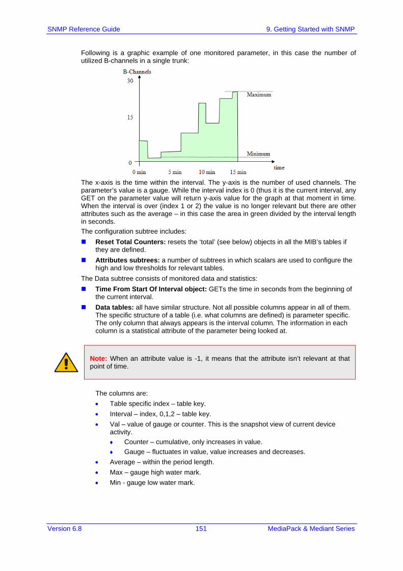
SNMP Reference Guide 9. Getting Started with SNMP
Version 6.8 151 MediaPack & Mediant Series
Following is a graphic example of one monitored parameter, in this case the number of utilized B-channels in a single trunk:
The x-axis is the time within the interval. The y-axis is the number of used channels. The parameter’s value is a gauge. While the interval index is 0 (thus it is the current interval, any GET on the parameter value will return y-axis value for the graph at that moment in time. When the interval is over (index 1 or 2) the value is no longer relevant but there are other attributes such as the average – in this case the area in green divided by the interval length in seconds. The configuration subtree includes: Reset Total Counters: resets the ‘total’ (see below) objects in all the MIB’s tables if
they are defined. Attributes subtrees: a number of subtrees in which scalars are used to configure the
high and low thresholds for relevant tables. The Data subtree consists of monitored data and statistics: Time From Start Of Interval object: GETs the time in seconds from the beginning of
the current interval. Data tables: all have similar structure. Not all possible columns appear in all of them.
The specific structure of a table (i.e. what columns are defined) is parameter specific. The only column that always appears is the interval column. The information in each column is a statistical attribute of the parameter being looked at.
Note: When an attribute value is -1, it means that the attribute isn’t relevant at that point of time.
The columns are: • Table specific index – table key. • Interval – index, 0,1,2 – table key. • Val – value of gauge or counter. This is the snapshot view of current device
activity. ♦ Counter – cumulative, only increases in value. ♦ Gauge – fluctuates in value, value increases and decreases.
• Average – within the period length. • Max – gauge high water mark. • Min - gauge low water mark.

MediaPack & Mediant Series
SNMP Reference Guide 152 Document #: LTRT-52379
• Volume – number of times gauge or counter was updated, indicating the volume of change. For example: ♦ For a trunk utilization element, the volume indicates how many calls were
made and released. ♦ For the Ethernet connection status element, the volume indicates how many
network connections and disconnections occurred. • TimeBelowLowThreshod – Percent of interval time for which the gauge is below
the determined low threshold. • TimeAboveHighThreshod – Percent of interval time for which the gauge is above
the determined high threshold. • TimeBetweenThresholds – Percent of interval time for which the gauge is
between thresholds. • FullDayAverage – 24 hour average. • Total – relevant when using counters. Sums all counter values so far. It resets
only once every 24 hours. • StateChanges – the number of times a state (mostly active/non-active) was
toggled. The log trap, acPerformanceMonitoringThresholdCrossing (non-alarm) is sent out every time the threshold of a Performance Monitored object ('Minimum', 'Average', 'Maximum', 'Distribution below/above/between thresholds', and 'Low and high thresholds') is crossed.. The severity field is 'Indeterminate' when the crossing is above the threshold and 'Cleared' when it returns to under the threshold. The 'Source' varbind in the trap indicates the object for which the threshold is being crossed. Expansions for the different MIBs. acPMMedia: Consists of data related to voice, DSPs coders etc. This MIB includes the
following parameters: • Number of active DSP channels • Channels used for each coder • Discarded packets in robust RTP filter • Media Networking subtree - an array of packet behavior parameters such as
delay, jitter, transmitted/received and lost RTP bytes and packets. • Media Networking Aggregated subtree - displays similar data only for the entire
device and includes TDM-IP and IP-IP calls. • Channel Utilization subtree - parameters regarding channel use by fax, modem,
TDM-IP calls, RTP, SRTP, multicast source and modem relay. • Streaming Cache subtree - hit count, miss count and server request count.
acPMControl: Control Protocol related monitoring is divided into three groups – MEGACO, MGCP and SIP. The MIB includes the following parameters: • CP Connection subtree – general for all three control protocols. Its parameters
include connection lifetime/state, counters for commands, retransmissions, active contexts, command success/failure and process time, transaction processing time and call attempts.
• The remaining three subtrees are self-explanatory and are CP specific. acPMAnalog: Analog channels statistics - one table only (offhook state). acPMPSTN: All statistics in this MIB are per trunk:
• Number of active channels. • Trunk activity. • Number of channels that are in/out of service and in maintenance.

SNMP Reference Guide 9. Getting Started with SNMP
Version 6.8 153 MediaPack & Mediant Series
acPMSystem: This detailed MIB is for general (system related) monitoring: • IP connection. • Discarded UDP packets due to unknown port. • System Net Utils subtree – transmitted/received bytes/packets, discarded
packets. • System Network subtree – DHCP response time/request count. STUN related
statistics. • IPsec security associations. (Applicable only to MP, Mediant 1000, Mediant 2000,
Mediant 3000) • System Multicast subtree – multicast IP packets received, multicast IP packets
conveying UDP payload packets received/rejected, IGMP packets/general-queries/specific-queries received, IGMP membership-report/leave-group sent messages.
• System Congestion subtree – congestion state for general resources, DSP resources, IP resources, conference resources. (ATM resources table is obsolete).
• System NFS subtree – NFS related parameters. • System MSBG subtree – includes received good/bad octets, received
undersized/oversized/discarded packets, received MAC errors, received FSC error packets, transmitted octets/packets/collisions/late-packets.
acPMMediaServer: (Applicable to the 3000/6310/8410 devices) The Media Server related data is divided into four subtrees: • IVR subtree – play requests, play progress/duration/collect/collect-in-
progress/collect-duration/record/record-in-progress/record-duration, digit-collect requests, digit-collect in-progress/duration.
• BCT subtree – BCT contexts, BCT in-progress/duration. • Conference subtree – conference calls, conference in-progress/duration. • Trunk Test subtree – trunk test requested, trunk tests in-progress/duration.
9.4 Traps and Alarms AudioCodes supports standard traps and proprietary traps. Most of the proprietary traps are alarm traps, that is, they can be raised and cleared. Thus, they are referred to as alarm traps. All the standard traps are non-alarm traps, referred to as log traps. The complete list of all supported traps is mentioned in previous subsections. The proprietary traps are defined under the acBoardTrapDefinitions subtree. The standard MIB traps supported include the following: coldStart authenticationFailure linkDown linkup dsx1LineStatusChange rtcpXrVoipThresholdViolation dsx3LineStatusChange entConfigChange This subsection describes the device’s configuration so that traps are sent out to user-defined managers under SNMPv2c or SNMPv3. It continues with an explanation on the ‘carrier grade alarm’ abilities and usage.

MediaPack & Mediant Series
SNMP Reference Guide 154 Document #: LTRT-52379
9.4.1 Device Configuration For a device to send out traps to specified managers the most basic configuration are the trap targets. More advanced configuration includes the Trap Community String or traps over SNMPv3. Destination IP address and port (see Basic SNMP Configuration Setup) Trap Community String: The default Trap Community String is ‘trapuser’. There is only
1 for the entire device. It can be configured via ini file, SNMP or Web: • INI file: SNMPTRAPCOMMUNITYSTRING = <your community string here>. • SNMP: add a new community string to the snmpCommunityTable. To associate
the traps to the new Community String change the snmpTargetParamsSecurityName in the snmpTargetParamsTable so it coincides with the snmpCommunitySecurityName object. If you wish, you can remove the older Trap Community String from snmpCommunityTable (however, it is not mandatory).
• Web: under the ‘Management’ tab, choose ‘Management Settings’ in the ‘Management Settings’ menu. On the page, click the SNMP Community String arrow to display the table. Use the Submit button to apply your configuration. You can’t delete the Trap Community String, only modify its value.
SNMPv3 Settings: When using SNMPv3 settings it is important to note that by default the trap configuration remains such that the traps are sent out in SNMPv2c mode. To have traps sent out in SNMPv3, you can use either ini file or SNMP: • INI file: amongst the SNMPv3 users ensure that you also define a trap user (the
value of 2 in the SNMPUsers_Group indicates the trap user). For example: you can have the SNMP users table defined with a read-write user, ‘rwmd5des’ with MD5 authentication and DES privacy, along with a trap user, ‘tmd5no’ with SHA authentication and DES privacy: [ SNMPUsers ] FORMAT SNMPUsers_Index = SNMPUsers_Username, SNMPUsers_AuthProtocol, SNMPUsers_PrivProtocol, SNMPUsers_AuthKey, SNMPUsers_PrivKey, SNMPUsers_Group; SNMPUsers 1 = rwmd5des, 1, 1, myauthkey, myprivkey, 1; SNMPUsers 2 = tshades, 2, 1, myauthkey, myprivkey, 2 [ \SNMPUsers ]
Notes:
• If you define a trap user only, the device runs in SNMPv3 mode but will not be accessible as there are no defined read-write or even read-only users.
• If you define non-default community strings (SNMPv2c), you need to access the device via SNMPv2c.
Along with this configuration, you also need to associate the trap targets (managers) with the user: SNMPMANAGERTRAPUSER_x=tshades
where x is the target index and can be between 0 and 4. Any targets that are defined in the ini file where this last parameter isn’t defined, receives SNMPv2c traps.
• SNMP: change snmpTargetAddrParams object to the user of your choice adding the letters ‘usm’ as prefix (ensure it’s a trap user). For example, the ‘tshades’ user should be added as ‘usmtshades’.

SNMP Reference Guide 9. Getting Started with SNMP
Version 6.8 155 MediaPack & Mediant Series
9.4.2 Carrier Grade Alarm (CGA) A carrier-grade alarm system provides a reliable alarm reporting mechanism that takes into account element management system outages, network outages, and transport mechanism such as SNMP over UDP. A carrier-grade alarm system is characterized by the following: The device allows a manager to determine which alarms are currently active in the
device. That is, the device maintains an active alarm table. The device allows a manager to detect lost alarms and clear notifications (sequence
number in trap, current sequence number MIB object). The device allows a manager to recover lost alarm raise and clear notifications
(maintains a log history). The device sends a cold start trap to indicate that it is starting. This allows the
manager to synchronize its view of the device's active alarms. When the SNMP alarm traps are sent, the carrier-grade alarm system does not add or delete alarm traps as part of the feature. This system provides the mechanism for viewing history and current active alarm information. As part of CGA, the device supports the following: Active Alarm Table: The device maintains an active alarm table to allow an EMS to
determine which alarms are currently active in the device. Two views of the active alarm table are supported by the agent: • acActiveAlarmTable in the proprietary AcAlarm MIB (this is a simple, one-row per
alarm table that is easy to view with a MIB browser) • alarmActiveTable and alarmActiveVariableTable in the IETF standard AcAlarm
MIB (rooted in the MIB tree) Alarm History: The device maintains a history of alarms that have been raised and
traps that have been cleared to allow an EMS to recover any lost raised or cleared traps. Two views of the alarm history table are supported by the agent: • acAlarmHistoryTable in the proprietary AcAlarm MIB (this is a simple, one-row per
alarm table that is easy to view with a MIB browser) • nlmLogTable and nlmLogVariableTable in the standard NOTIFICATION-LOG-MIB • This page is intentionally left blank.