Embed Size (px)
Citation preview

SoaringDigestRadio C ntrolled
February 2017 Vol. 34, No. 2
2 R/C Soaring Digest
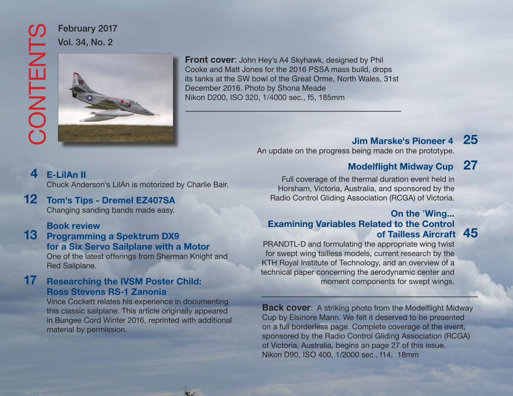
Front cover: John Hey's A4 Skyhawk, designed by Phil Cooke and Matt Jones for the 2016 PSSA mass build, drops its tanks at the SW bowl of the Great Orme, North Wales, 31st December 2016. Photo by Shona Meade Nikon D200, ISO 320, 1/4000 sec., f5, 185mm
February 2017
Vol. 34, No. 2C
ON
TEN
TS
4 E-LilAn II Chuck Anderson's LilAn is motorized by Charlie Bair.
12 Tom's Tips - Dremel EZ407SA Changing sanding bands made easy.
Book review 13 Programming a Spektrum DX9
for a Six Servo Sailplane with a MotorOne of the latest offerings from Sherman Knight and Red Sailplane.
17 Researching the IVSM Poster Child: Ross Stevens RS-1 Zanonia Vince Cockett relates his experience in documenting this classic sailplane. This article originally appeared in Bungee Cord Winter 2016, reprinted with additional material by permission.
Jim Marske's Pioneer 4 25An update on the progress being made on the prototype.
Modelflight Midway Cup 27Full coverage of the thermal duration event held in
Horsham, Victoria, Australia, and sponsored by the Radio Control Gliding Association (RCGA) of Victoria.
On the ’Wing... Examining Variables Related to the Control
of Tailless Aircraft 45PRANDTL-D and formulating the appropriate wing twist for swept wing tailless models, current research by the
KTH Royal Institute of Technology, and an overview of a technical paper concerning the aerodynamic center and
moment components for swept wings.
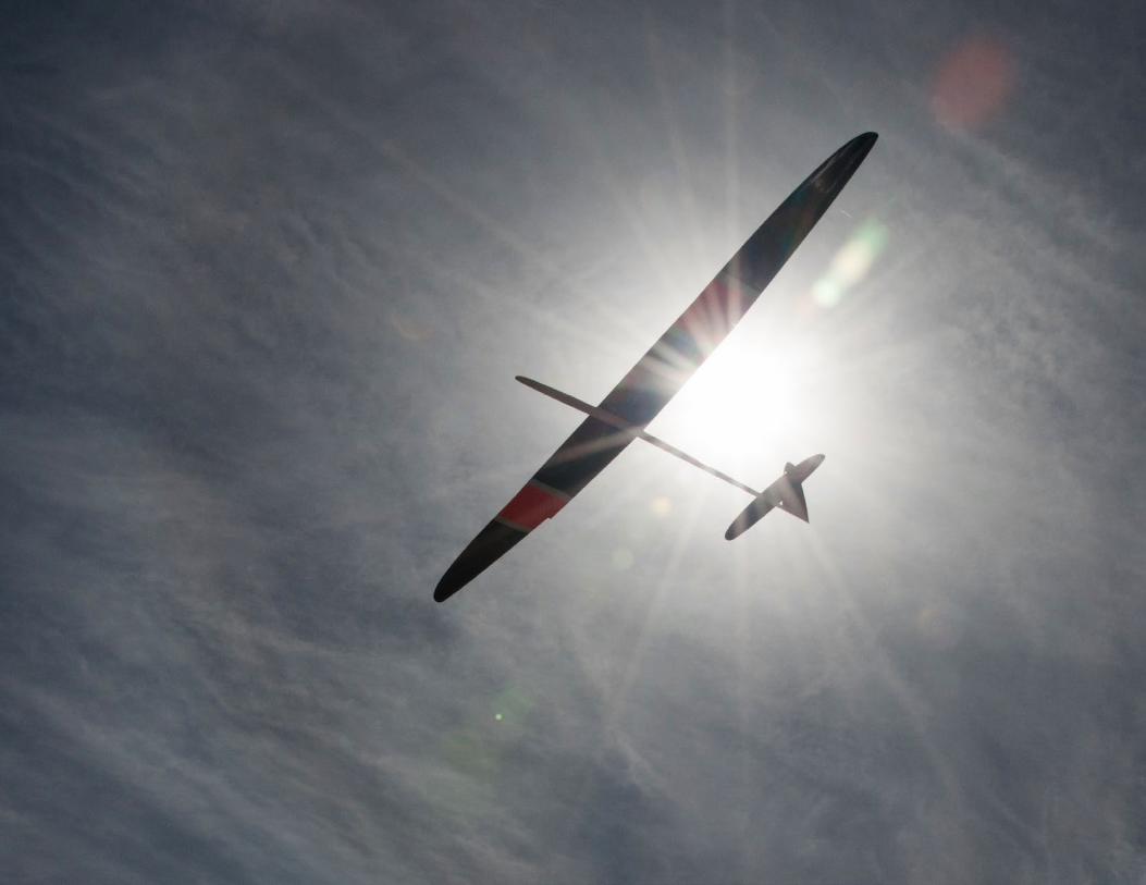
Back cover: A striking photo from the Modelflight Midway Cup by Elsinore Mann. We felt it deserved to be presented on a full borderless page. Complete coverage of the event, sponsored by the Radio Control Gliding Association (RCGA) of Victoria, Australia, begins an page 27 of this issue. Nikon D90, ISO 400, 1/2000 sec., f14, 18mm
February 2017 3
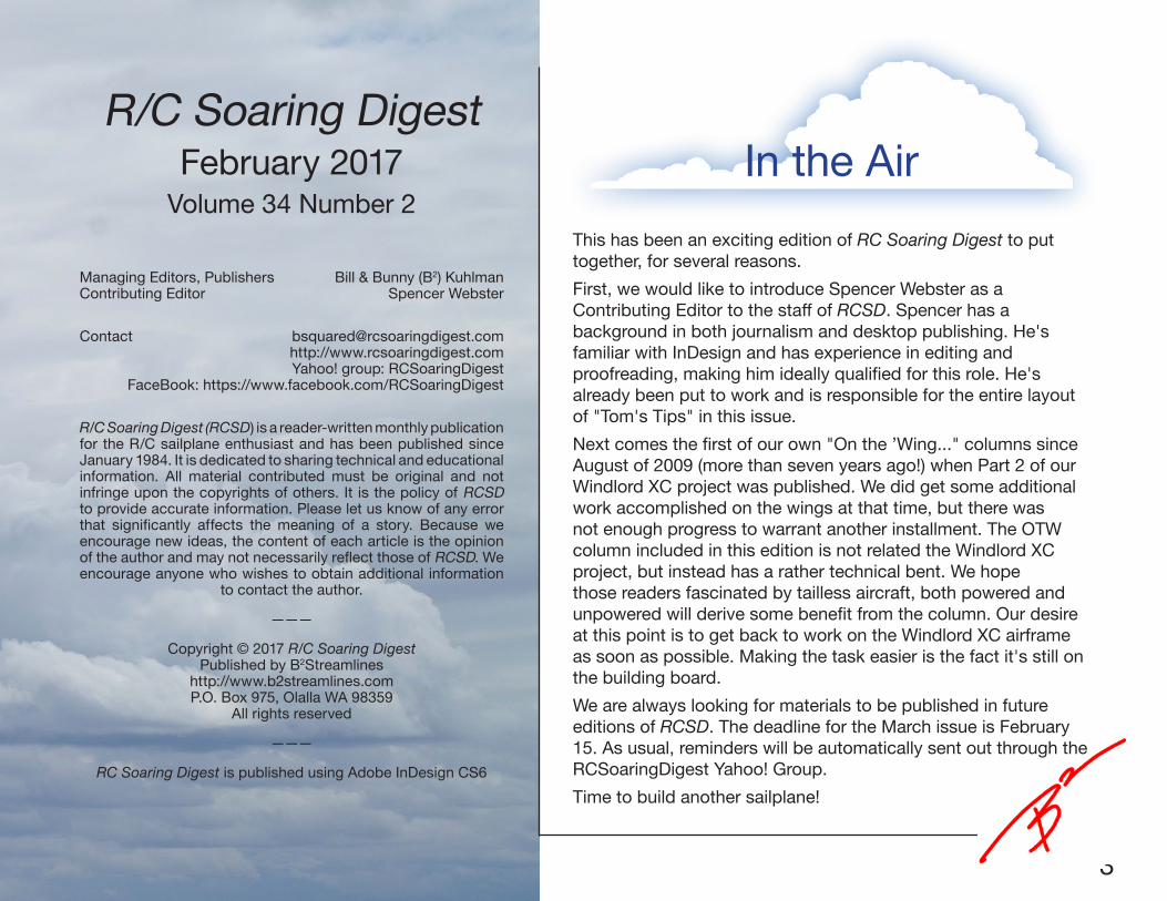
R/C Soaring DigestFebruary 2017
Volume 34 Number 2
Managing Editors, Publishers Bill & Bunny (B2) KuhlmanContributing Editor Spencer Webster
Contact [email protected]://www.rcsoaringdigest.comYahoo! group: RCSoaringDigest
FaceBook: https://www.facebook.com/RCSoaringDigest
R/C Soaring Digest (RCSD) is a reader-written monthly publication for the R/C sailplane enthusiast and has been published since January 1984. It is dedicated to sharing technical and educational information. All material contributed must be original and not infringe upon the copyrights of others. It is the policy of RCSD to provide accurate information. Please let us know of any error that significantly affects the meaning of a story. Because we encourage new ideas, the content of each article is the opinion of the author and may not necessarily reflect those of RCSD. We encourage anyone who wishes to obtain additional information
to contact the author.
———
Copyright © 2017 R/C Soaring DigestPublished by B2Streamlines
http://www.b2streamlines.comP.O. Box 975, Olalla WA 98359
All rights reserved
———
RC Soaring Digest is published using Adobe InDesign CS6
This has been an exciting edition of RC Soaring Digest to put together, for several reasons.
First, we would like to introduce Spencer Webster as a Contributing Editor to the staff of RCSD. Spencer has a background in both journalism and desktop publishing. He's familiar with InDesign and has experience in editing and proofreading, making him ideally qualified for this role. He's already been put to work and is responsible for the entire layout of "Tom's Tips" in this issue.
Next comes the first of our own "On the ’Wing..." columns since August of 2009 (more than seven years ago!) when Part 2 of our Windlord XC project was published. We did get some additional work accomplished on the wings at that time, but there was not enough progress to warrant another installment. The OTW column included in this edition is not related the Windlord XC project, but instead has a rather technical bent. We hope those readers fascinated by tailless aircraft, both powered and unpowered will derive some benefit from the column. Our desire at this point is to get back to work on the Windlord XC airframe as soon as possible. Making the task easier is the fact it's still on the building board.
We are always looking for materials to be published in future editions of RCSD. The deadline for the March issue is February 15. As usual, reminders will be automatically sent out through the RCSoaringDigest Yahoo! Group.
Time to build another sailplane!
In the Air
4 R/C Soaring Digest
E-LilAn II the evolutionCharlie Bair
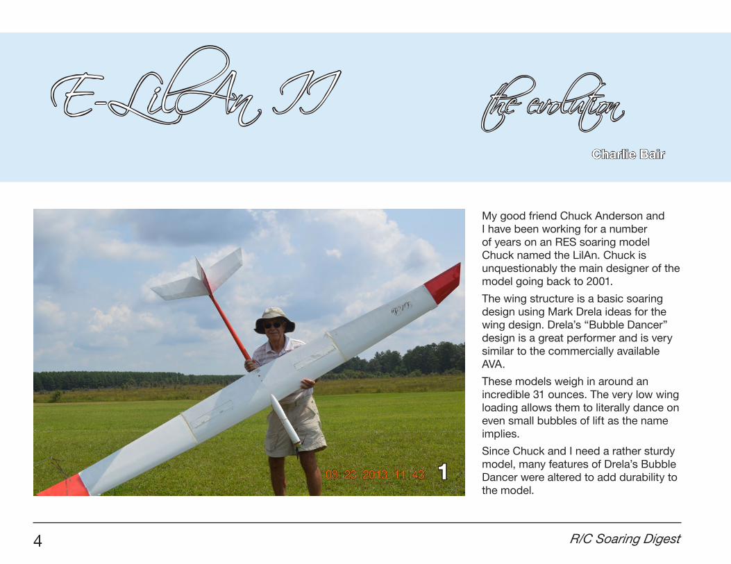
My good friend Chuck Anderson and I have been working for a number of years on an RES soaring model Chuck named the LilAn. Chuck is unquestionably the main designer of the model going back to 2001.
The wing structure is a basic soaring design using Mark Drela ideas for the wing design. Drela’s “Bubble Dancer” design is a great performer and is very similar to the commercially available AVA.
These models weigh in around an incredible 31 ounces. The very low wing loading allows them to literally dance on even small bubbles of lift as the name implies.
Since Chuck and I need a rather sturdy model, many features of Drela’s Bubble Dancer were altered to add durability to the model.
1
February 2017 5
Winch launched competition soaring models need to undergo dreadful loads from launch to landing. Some of the greatest of these are the winch launch and landing themselves.
Chuck also considers what he calls “door loads.” These are the structural loads imposed on the airframe as it strikes doorways while loading and unloading the model from shop to vehicles. Don’t tell me you have not encountered these.
As for winch loads, I speak for myself. Nearly all my soaring mishaps have occurred on launch. Usually this is from an overzealous foot on the winch pedal. While I prefer to actually land my models, during contests it’s far too tempting to put the nose on the goal landing spot no matter what the speed or sink rate. Very hard on carbon booms, and V mounted stabs. So, it seemed wise for us to back off the 31 ounce goal, and add some durability.
Chuck initially built a mold to make a fuselage with an integral tail boom. The horizontal stabilizers pivot on the vertical stabilizer instead of a more fragile V-mount.
Wing construction is a rather standard single spar made up of carbon fiber caps epoxied to a balsa shear web and is wrapped with kevlar tow. We added a longer wrap of lite fiberglass cloth near
the wing joints after we had some failures there.
There is a center panel, and right and left outer panels. While these features result in increased weight, the model soars well. I wonder at times if it’s worth reducing weight to extremes just to add ballast so we can handle winds.
Over the years we have built and flown nine of these models, some enduring hundreds of flights and a number of contests.
Previous articles in this publication detail specifics on the design, construction, and flying. Now the popularity of electric powered gliders prompted us to add a motor to our LilAn design as shown in the photo on the title page [Photo 1].
The first E-LilAn was created by adding a Radian size prop and motor to LilAn Number 5 just for fun in order to fly without having to haul a winch to the field.
The LilAn 5 wing was damaged by flutter in an over aggressive zoom launch and wing repairs never completely solved the winch launch flutter problem. This gave us a good use for wings that were weakened by mishaps and were not reparable with sufficient strength to withstand winch loads.
While underpowered for ALES competition, it still had sufficient power
to get to a 200 meter altitude but required more than 30 seconds unless launched in lift.
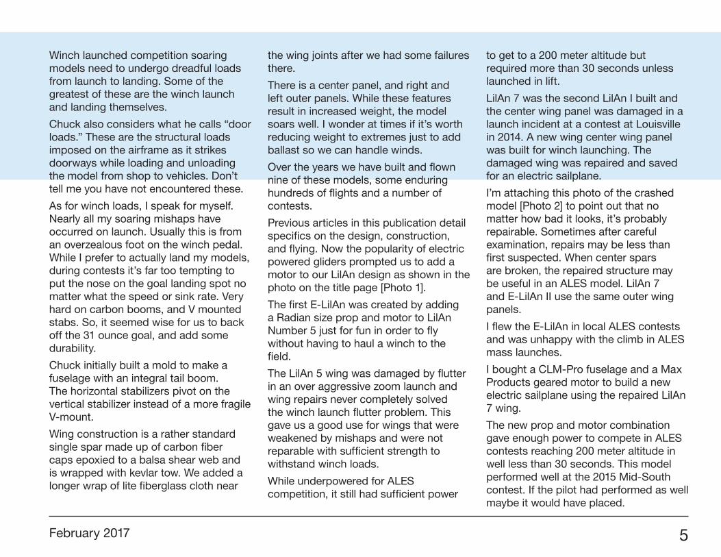
LilAn 7 was the second LilAn I built and the center wing panel was damaged in a launch incident at a contest at Louisville in 2014. A new wing center wing panel was built for winch launching. The damaged wing was repaired and saved for an electric sailplane.
I’m attaching this photo of the crashed model [Photo 2] to point out that no matter how bad it looks, it’s probably repairable. Sometimes after careful examination, repairs may be less than first suspected. When center spars are broken, the repaired structure may be useful in an ALES model. LilAn 7 and E-LilAn II use the same outer wing panels.
I flew the E-LilAn in local ALES contests and was unhappy with the climb in ALES mass launches.
I bought a CLM-Pro fuselage and a Max Products geared motor to build a new electric sailplane using the repaired LilAn 7 wing.
The new prop and motor combination gave enough power to compete in ALES contests reaching 200 meter altitude in well less than 30 seconds. This model performed well at the 2015 Mid-South contest. If the pilot had performed as well maybe it would have placed.
6 R/C Soaring Digest
Here are some of the details we worked through to put this model together.
We were pleased with the quality of the fuselage from CLM-pro.com. The sleek slender design of this fuselage made installation of the components a challenge. My partner Chuck Anderson constantly emphasized that there was no significant aerodynamic benefit in such a skinny design at the airspeeds this model would be flying. OK, Chuck, but it looks cool. We have to acknowledge that Chuck does have many years of wind tunnel testing experience.
So, here are a few of the tricks and methods we used to get everything packed in that cool skinny fuselage. The stab, fin, and rudder are the same as the LilAn Omega and the construction is covered in the April 2016 issue of RC Soaring Digest while installation is covered in the May 2016 issue.
The Max Products geared motor fits nicely. It’s small overall diameter slips neatly into the nose. The power leads come out the back of the motor, another nice feature. Surely this installation is a piece of cake.
Well, maybe not. There is very little space to work with around the motor location in the nose. The mounting holes on the front of the motor are very close together. Locating the holes on the fuselage firewall is a challenge. We were not satisfied with the initial attempt to mount the motor directly to the firewall.
2
The crash of the LilAn 7.
February 2017 7
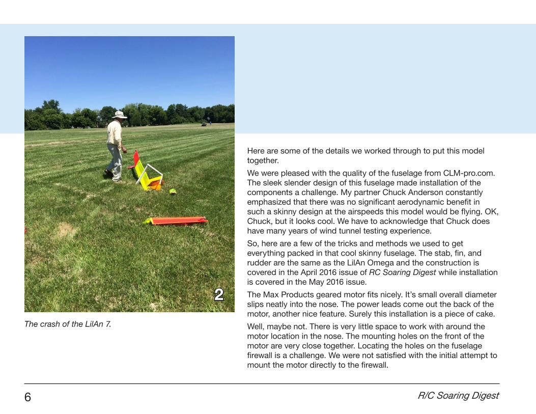
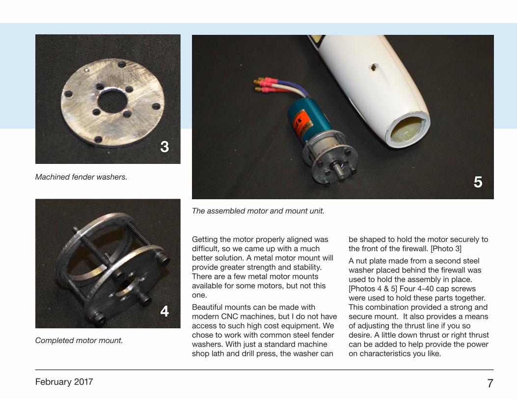
Getting the motor properly aligned was difficult, so we came up with a much better solution. A metal motor mount will provide greater strength and stability. There are a few metal motor mounts available for some motors, but not this one.
Beautiful mounts can be made with modern CNC machines, but I do not have access to such high cost equipment. We chose to work with common steel fender washers. With just a standard machine shop lath and drill press, the washer can
be shaped to hold the motor securely to the front of the firewall. [Photo 3]
A nut plate made from a second steel washer placed behind the firewall was used to hold the assembly in place. [Photos 4 & 5] Four 4-40 cap screws were used to hold these parts together. This combination provided a strong and secure mount. It also provides a means of adjusting the thrust line if you so desire. A little down thrust or right thrust can be added to help provide the power on characteristics you like.
3
4
5Machined fender washers.
Completed motor mount.
The assembled motor and mount unit.
8 R/C Soaring Digest
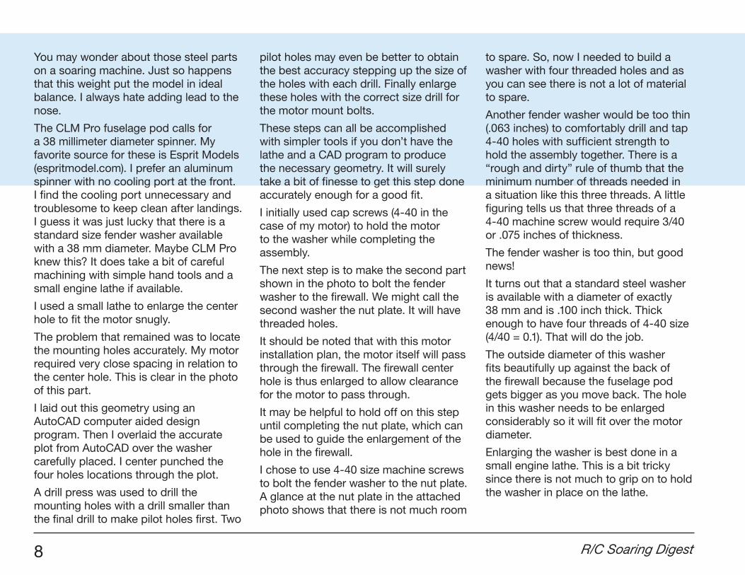
You may wonder about those steel parts on a soaring machine. Just so happens that this weight put the model in ideal balance. I always hate adding lead to the nose.
The CLM Pro fuselage pod calls for a 38 millimeter diameter spinner. My favorite source for these is Esprit Models (espritmodel.com). I prefer an aluminum spinner with no cooling port at the front. I find the cooling port unnecessary and troublesome to keep clean after landings. I guess it was just lucky that there is a standard size fender washer available with a 38 mm diameter. Maybe CLM Pro knew this? It does take a bit of careful machining with simple hand tools and a small engine lathe if available.
I used a small lathe to enlarge the center hole to fit the motor snugly.
The problem that remained was to locate the mounting holes accurately. My motor required very close spacing in relation to the center hole. This is clear in the photo of this part.
I laid out this geometry using an AutoCAD computer aided design program. Then I overlaid the accurate plot from AutoCAD over the washer carefully placed. I center punched the four holes locations through the plot.
A drill press was used to drill the mounting holes with a drill smaller than the final drill to make pilot holes first. Two
pilot holes may even be better to obtain the best accuracy stepping up the size of the holes with each drill. Finally enlarge these holes with the correct size drill for the motor mount bolts.
These steps can all be accomplished with simpler tools if you don’t have the lathe and a CAD program to produce the necessary geometry. It will surely take a bit of finesse to get this step done accurately enough for a good fit.
I initially used cap screws (4-40 in the case of my motor) to hold the motor to the washer while completing the assembly.
The next step is to make the second part shown in the photo to bolt the fender washer to the firewall. We might call the second washer the nut plate. It will have threaded holes.
It should be noted that with this motor installation plan, the motor itself will pass through the firewall. The firewall center hole is thus enlarged to allow clearance for the motor to pass through.
It may be helpful to hold off on this step until completing the nut plate, which can be used to guide the enlargement of the hole in the firewall.
I chose to use 4-40 size machine screws to bolt the fender washer to the nut plate. A glance at the nut plate in the attached photo shows that there is not much room
to spare. So, now I needed to build a washer with four threaded holes and as you can see there is not a lot of material to spare.
Another fender washer would be too thin (.063 inches) to comfortably drill and tap 4-40 holes with sufficient strength to hold the assembly together. There is a “rough and dirty” rule of thumb that the minimum number of threads needed in a situation like this three threads. A little figuring tells us that three threads of a 4-40 machine screw would require 3/40 or .075 inches of thickness.
The fender washer is too thin, but good news!
It turns out that a standard steel washer is available with a diameter of exactly 38 mm and is .100 inch thick. Thick enough to have four threads of 4-40 size (4/40 = 0.1). That will do the job.
The outside diameter of this washer fits beautifully up against the back of the firewall because the fuselage pod gets bigger as you move back. The hole in this washer needs to be enlarged considerably so it will fit over the motor diameter.
Enlarging the washer is best done in a small engine lathe. This is a bit tricky since there is not much to grip on to hold the washer in place on the lathe.
February 2017 9
If you don’t have such equipment, there may be a local high school that teaches some of these skills. The teacher may be willing to have a student do this job for practice and all you’d have to lose is a 10-cent washer.
Next, the holes need to be located for the four machine screws that hold the mount to the firewall. This needs to be done carefully since there is little material for the threaded holes.
This is clear as you view the picture of the nut plate. The exact spacing of these holes is irrelevant as long as the holes are matched up on the mount’s fender washer.
Here is how I went about this.
First I mounted the motor to the fender washer with 4-40 cap screws. This may be different if you have a different motor.
Locate the centers of the machine screws on the nut plate. Drill them out with a pilot drill smaller than the tap drill size. Then, place the nut plate over the motor and slide it up against the fender washer.
Rotate it to the position you wish to use and clamp it in place while you use the pilot holes in the nut plate to locate the holes in the fender washer. You can use this assembly to guide the same pilot drill to drill through the fender washer.
With the pilot holes drilled through, disassemble the mounting parts, and drill out the fender washer to a size for the mounting bolts to pass through freely.
Use a tap drill to drill out the holes in the nut plate. Do not use an oversize drill for these holes because you want maximum strength in the threads in the nut plate. Some machinists drill these oversize to make tapping easier, but in this case you need to take pains in making these threads as strong as possible.
Clean up the parts with a file and emery cloth to remove burrs and finish the parts off.
Put the final assembly together. I used cap screws up to this point for convenience, but the holes in the fender washer must be countersunk and flat head machine screws substituted for final assembly to provide clearance for the prop and spinner parts.
This mount held up well for many flights, and should last a long time.
The motor can be removed if necessary for maintenance or replacement when necessary.
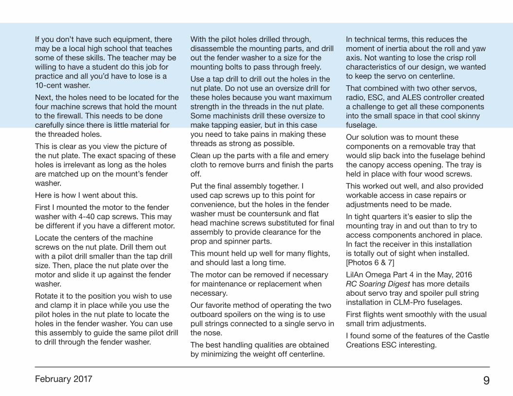
Our favorite method of operating the two outboard spoilers on the wing is to use pull strings connected to a single servo in the nose.
The best handling qualities are obtained by minimizing the weight off centerline.
In technical terms, this reduces the moment of inertia about the roll and yaw axis. Not wanting to lose the crisp roll characteristics of our design, we wanted to keep the servo on centerline.
That combined with two other servos, radio, ESC, and ALES controller created a challenge to get all these components into the small space in that cool skinny fuselage.
Our solution was to mount these components on a removable tray that would slip back into the fuselage behind the canopy access opening. The tray is held in place with four wood screws.
This worked out well, and also provided workable access in case repairs or adjustments need to be made.
In tight quarters it’s easier to slip the mounting tray in and out than to try to access components anchored in place. In fact the receiver in this installation is totally out of sight when installed. [Photos 6 & 7]
LilAn Omega Part 4 in the May, 2016 RC Soaring Digest has more details about servo tray and spoiler pull string installation in CLM-Pro fuselages.
First flights went smoothly with the usual small trim adjustments.
I found some of the features of the Castle Creations ESC interesting.
10 R/C Soaring Digest
6 7
The servo tray in place. Notice the spoiler activation system which is driven by a single servo and is entirely adjustable.
ELilAn II on the contest circuit.
February 2017 11
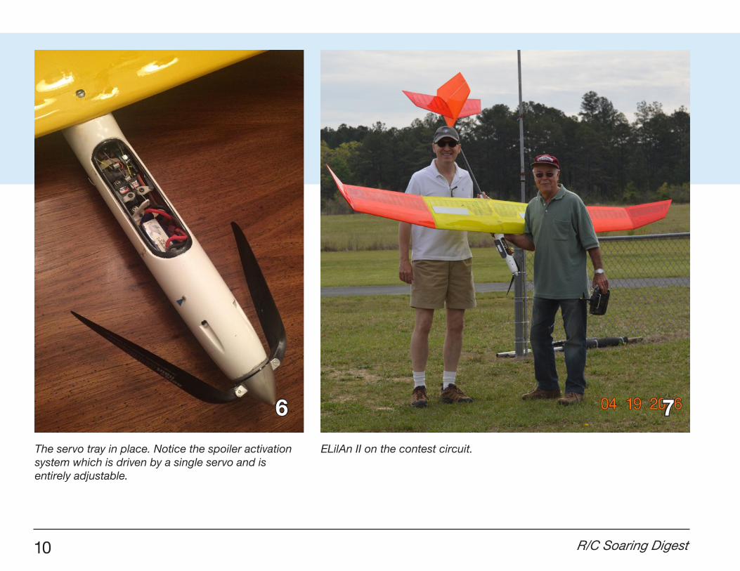
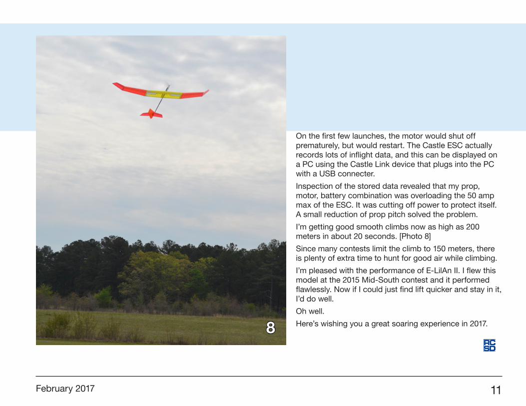
On the first few launches, the motor would shut off prematurely, but would restart. The Castle ESC actually records lots of inflight data, and this can be displayed on a PC using the Castle Link device that plugs into the PC with a USB connecter.
Inspection of the stored data revealed that my prop, motor, battery combination was overloading the 50 amp max of the ESC. It was cutting off power to protect itself. A small reduction of prop pitch solved the problem.
I’m getting good smooth climbs now as high as 200 meters in about 20 seconds. [Photo 8]
Since many contests limit the climb to 150 meters, there is plenty of extra time to hunt for good air while climbing.
I’m pleased with the performance of E-LilAn II. I flew this model at the 2015 Mid-South contest and it performed flawlessly. Now if I could just find lift quicker and stay in it, I’d do well.
Oh well.
Here’s wishing you a great soaring experience in 2017.8

12 R/C Soaring Digest
Tom’sips
Dremel EZ407SA
Tom Broeski, T&G Innovations LLC, [email protected]
Every once in awhile I find something that makes my work easier. This is one such product. It hasn’t been out too long, and I figured I’d share it with those who don’t know it exists.
If you have ever struggled with changing sanding bands on a Dremel tool, you will really appreciate this item.
Just slide the band on. It is very loose and goes on with the push of one finger.
This unit goes in your Dremel and you pull the rubber holder out.
Continue pressing and the band locks firmly in place and doesn’t slip at all.
These can be a real pain, especially if you change bands 10 to 20+ times a day as I often do.
To remove, simply pull it out.
Slide off the band and you are ready to start all over.
You can shop around since prices range from $4.99 at Amazon to $9 at Lowes, Home Depot or Ace (where I bought my first one).
February 2017 13
Frustrated with the programming challenges that come with Ailerons and Flaps on a sailplane? Tired of conflicting “how to” posts on line? If features like Differential, Adverse Yaw, Elevator Compensation, Aileron to Rudder mixing, Snap Flaps are new to you, then this Guide and SPM file are for you.
Everything you need for your Six Servo Sailplane with a Motor is provided. This bundle includes a 159 page Guide, three prepared SPM files for different wing configurations for you to import into your radio along with 23 new Flight Mode voices and a reorganized Audio file. All the rates, mixes and Flight Mode features are already programmed.
This latest version includes Cascading Priorities to reduce pilot load in the event of an emergency bailout.
The guide starts off explaining how to import the files into the radio, rename and organize them. The with the radio in your lap, the guide walks you through how the programming works from a generic perspective.
There is a new section on all the things you can do with telemetry like automatically announcing altitude at push over at the top of the climb.
Next, the guide shows you how to make simple modifications to the linkages and how to use Global Features to setup a neutral sailplane that is ready for programming. After performing this step, the preset values in the SPM file are going to be very close.
The guide then explains the Flight Mode Features in the prepared templates, how to build them from scratch and how to modify the
prepared templates for three, five and seven Flight Modes.
There is an new section on speed controllers with 4 different methods. Each method is described in full or each is available with just a couple of modifications of the prepared template. There is even a method with Flaps and Throttle on the same stick.
The next section discusses the way to modify the prepared template for your sailplane.
Book review
Programming a Spektrum DX9 for a
Six Servo Sailplane with a MotorSherman Knight, https://red-sailplane.myshopify.com/
14 R/C Soaring Digest
The last chapters are intended for the pilot stepping up to a aileron sailplane for the first time and discusses the new terminology that comes with an aileron sailplane, what the new control surfaces do and why and how to overcome issues like adverse yaw.
Finally, the Guide explains and how to make the critical CG determination so the final elevator trim setting for each Flight Mode work together and how and when to use the different Flight Modes.
The features include in the prepared templates include:
• As a safety feature, the radio will not turn on until you retract the flaps and turn off Launch Mode (so the motor does not accidently start during startup).• Elevator and Ailerons on the right stick and Rudder and Flaps on the left stick.• Five flight modes are active, Speed, Thermal, Cruise, Launch, and Land.• Throttle Cutoff on Switch H.
LAUNCH MODE: (announced with voice)• Launch Mode switch starts the motor. Please remove the propeller before you start programming.• Switch Selectable with priority over all other flight modes.• Differential rate of 70%.• Appropriate changes in Rates, and Aileron to Rudder mix.• Camber Slider is off.• Aileron to Flap mix is inactive.• Launch Mode Switch starts and stops the motor.• Launch Mode Switch starts the timers.• Throttle Cut Switch announced with voices.
CRUISE MODE: (announced with voice)• Neutral trailing edge Camber Preset.• Camber Slider is active. Camber Slider only droops the trailing edge.
• Appropriate changes in Rates, Differential and Aileron to Rudder mix.• Aileron to Flap mix is available with adjustable Flap Differential.• Snap Flap is active.• Additional down elevator to help push over at the top of the zoom.• Voice announces altitude automatically at pushover at the top of the zoom.
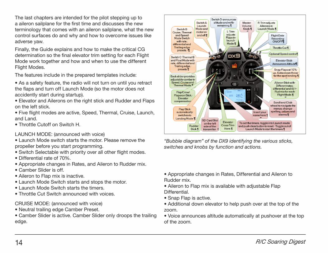
“Bubble diagram” of the DX9 identifying the various sticks, switches and knobs by function and actions.
February 2017 15
SPEED MODE: (announced with voice)• Reflexed trailing edge Preset.• Camber Slider is active. Camber Slider only droops the trailing edge.• Appropriate changes in Rates, Differential and Aileron to Rudder mix.• Additional down elevator to help push over at the top of the zoom.• Snap Flap is active.• Aileron to Flap mix is available with adjustable Flap Differential.• Voice announces altitude automatically at pushover at the top of the zoom.
THERMAL MODE: (announced with voice)• Drooped trailing edge Camber Preset.• Camber Slider is active. Camber Slider only droops the trailing edge.• Appropriate changes in Rates, Differential and Aileron to Rudder mix.• Aileron to Flap mix is available with adjustable Flap Differential.• Snap Flap is active.
LANDING MODE: (announced with voice)• Pulling the flap stick below 92% automatically activates Landing Mode.• The 92% kick point can be modified.• Adjustable Flap travel.• Two methods to match Flaps so they move together.• Either Flaperon or Crow.• Flap to Elevator compensation expo curve with seven points.• Appropriate changes in Rates, Differential, Aileron to Rudder mix.• Extra down elevator to help push over in the landing zone.• Master volume on the Right Knob. (if knob is available on your radio)• Option for cross trims, placing the elevator trim on the Flap Stick side.• Appropriate voices for each flight mode and telemetry if a telemetry module is installed.• A timer that keeps track of just the accumulated motor run time. Timer switch is linked to the Launch Mode Switch so the timer starts automatically when you switch into Launch Mode and stops when you
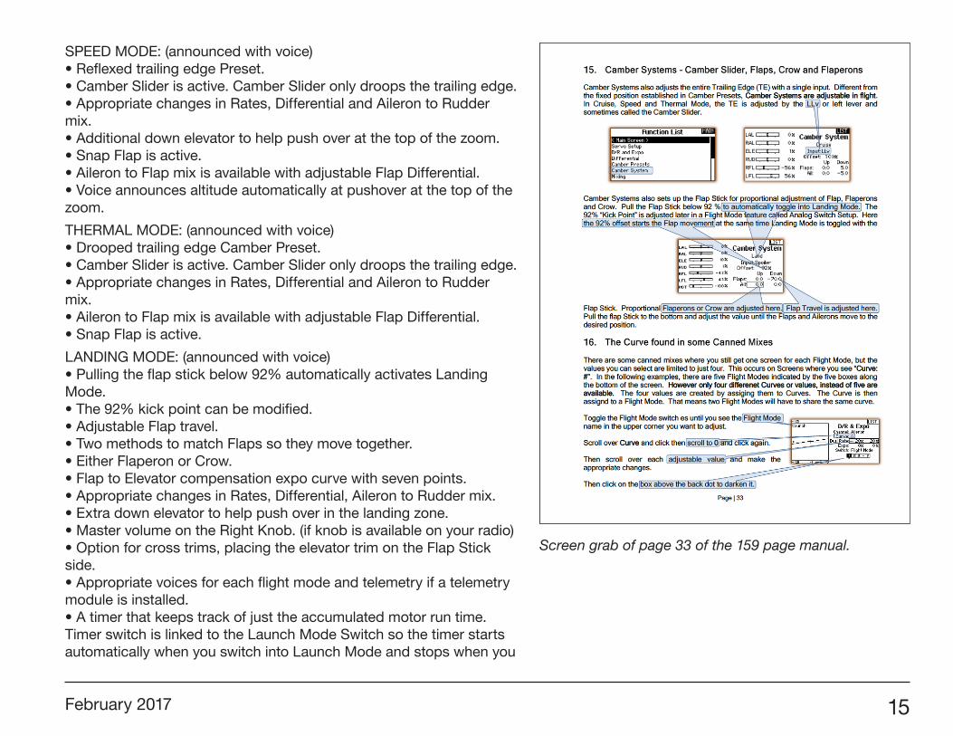
Screen grab of page 33 of the 159 page manual.
16 R/C Soaring Digest
toggle out of Launch Mode. Start and stop as often as you like and this timer will only track accumulated motor run time.• A second timer that keeps track of accumulated flight time. Timer switch is linked to the Launch Mode Switch so the timer starts automatically the first time you start the motor and continues running when you toggle out of Launch Mode to stop the motor. • If you have telemetry: (Either a TM1000 or one of the new telemetry enabled receivers)• Telemetry can be recorded for later playback.• You can track signal quality (by each individual antenna) between the transmitter and receiver and voltage without additional sensors.• Add either an altimeter or variometer sensor and the transmitter will announce altitude when you push over at the top of the zoom.• Add a current sensor and the transmitter will announce the gas remaining in the tank. (current left in the battery). This a WAY better method than tracking voltage. • Add a GPS sensor and you get straight line speed, distance from the pilot and location in the event you lose the aircraft.• Setup sensors for RPM (either motor or propeller if you have a gear box) or motor temperature. You can record telemetry A that is automatically saved to the SD card for later play back.• Switch D is setup to call out altitude on demand and mAh used on demand.
Red Sailplane is owned by Sherman Knight whom has been writing guides and templates for JR and Spektrum RC radio systems since 1991.
Six Servo Sailplane with Motor for the DX9 is available directly from <https://red-sailplane.myshopify.com/>.Regular price $ 24.95
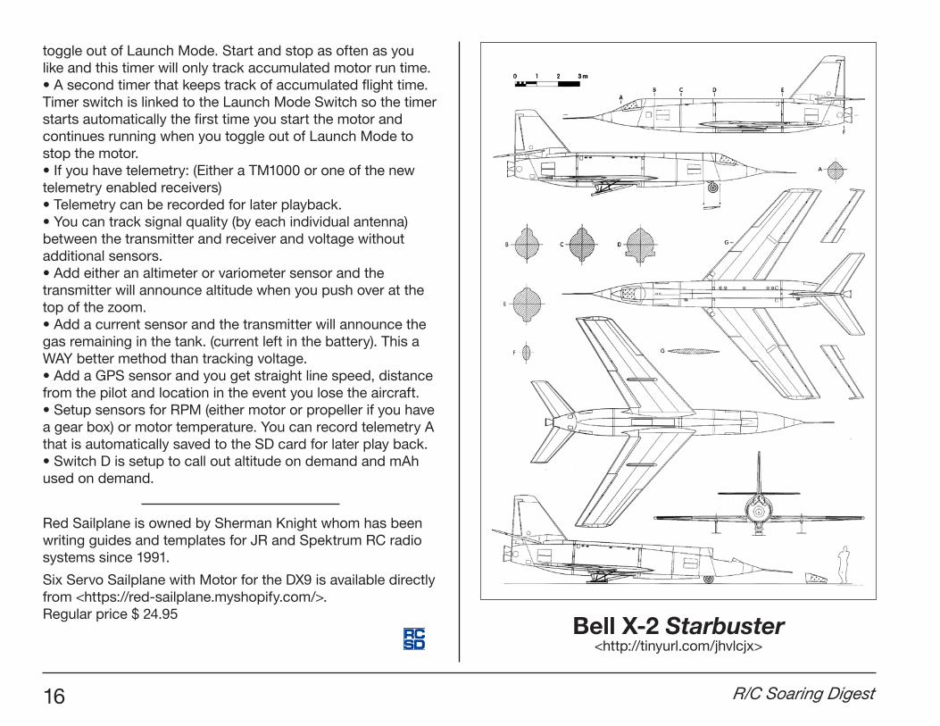
Bell X-2 Starbuster <http://tinyurl.com/jhvlcjx>
February 2017 17
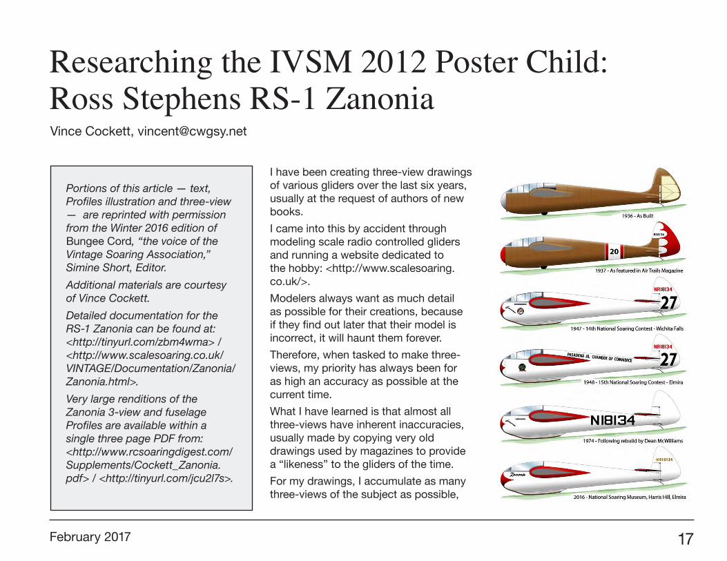
I have been creating three-view drawings of various gliders over the last six years, usually at the request of authors of new books.
I came into this by accident through modeling scale radio controlled gliders and running a website dedicated to the hobby: <http://www.scalesoaring.co.uk/>.
Modelers always want as much detail as possible for their creations, because if they find out later that their model is incorrect, it will haunt them forever.
Therefore, when tasked to make three-views, my priority has always been for as high an accuracy as possible at the current time.
What I have learned is that almost all three-views have inherent inaccuracies, usually made by copying very old drawings used by magazines to provide a “likeness” to the gliders of the time.
For my drawings, I accumulate as many three-views of the subject as possible,
Researching the IVSM 2012 Poster Child: Ross Stephens RS-1 Zanonia Vince Cockett, [email protected]
Portions of this article — text, Profiles illustration and three-view — are reprinted with permission from the Winter 2016 edition of Bungee Cord, “the voice of the Vintage Soaring Association,” Simine Short, Editor.
Additional materials are courtesy of Vince Cockett.
Detailed documentation for the RS-1 Zanonia can be found at: <http://tinyurl.com/zbm4wma> / <http://www.scalesoaring.co.uk/VINTAGE/Documentation/Zanonia/Zanonia.html>.
Very large renditions of the Zanonia 3-view and fuselage Profiles are available within a single three page PDF from: <http://www.rcsoaringdigest.com/Supplements/Cockett_Zanonia.pdf> / <http://tinyurl.com/jcu2l7s>.
18 R/C Soaring Digest
as many photos as can be found, and then I read up about its history.
A good example of my findings was the Wien, flown by Robert Kronfeld starting in 1929. The instruments and cockpit arrangements were never properly known, but the Wasserkuppe Museum had made a mockup with the information available at the time. What I had discovered about the Wien encouraged the Museum staff to redo their cockpit and even create new instruments to match my findings and drawings.
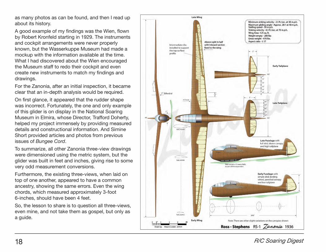
For the Zanonia, after an initial inspection, it became clear that an in-depth analysis would be required.
On first glance, it appeared that the rudder shape was incorrect. Fortunately, the one and only example of this glider is on display in the National Soaring Museum in Elmira, whose Director, Trafford Doherty, helped my project immensely by providing measured details and constructional information. And Simine Short provided articles and photos from previous issues of Bungee Cord.
To summarize, all other Zanonia three-view drawings were dimensioned using the metric system, but the glider was built in feet and inches, giving rise to some very odd measurement conversions.
Furthermore, the existing three-views, when laid on top of one another, appeared to have a common ancestry, showing the same errors. Even the wing chords, which measured approximately 3-foot 6-inches, should have been 4 feet.
So, the lesson to share is to question all three-views, even mine, and not take them as gospel, but only as a guide.
February 2017 19
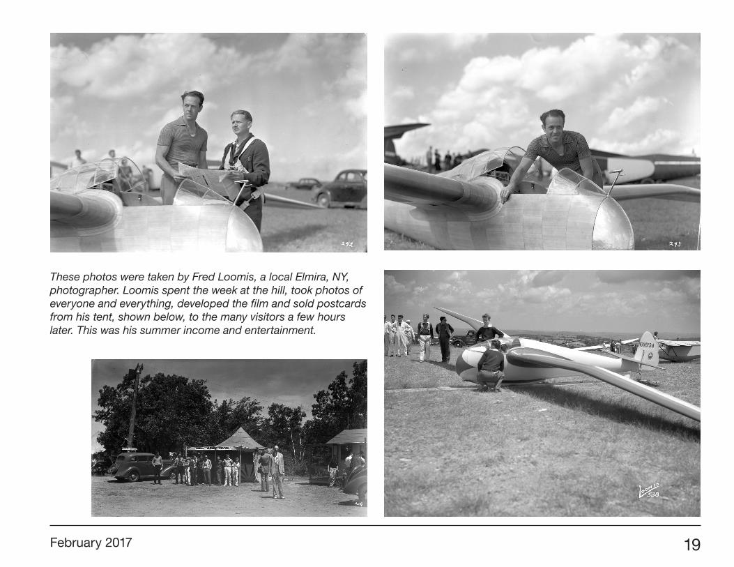
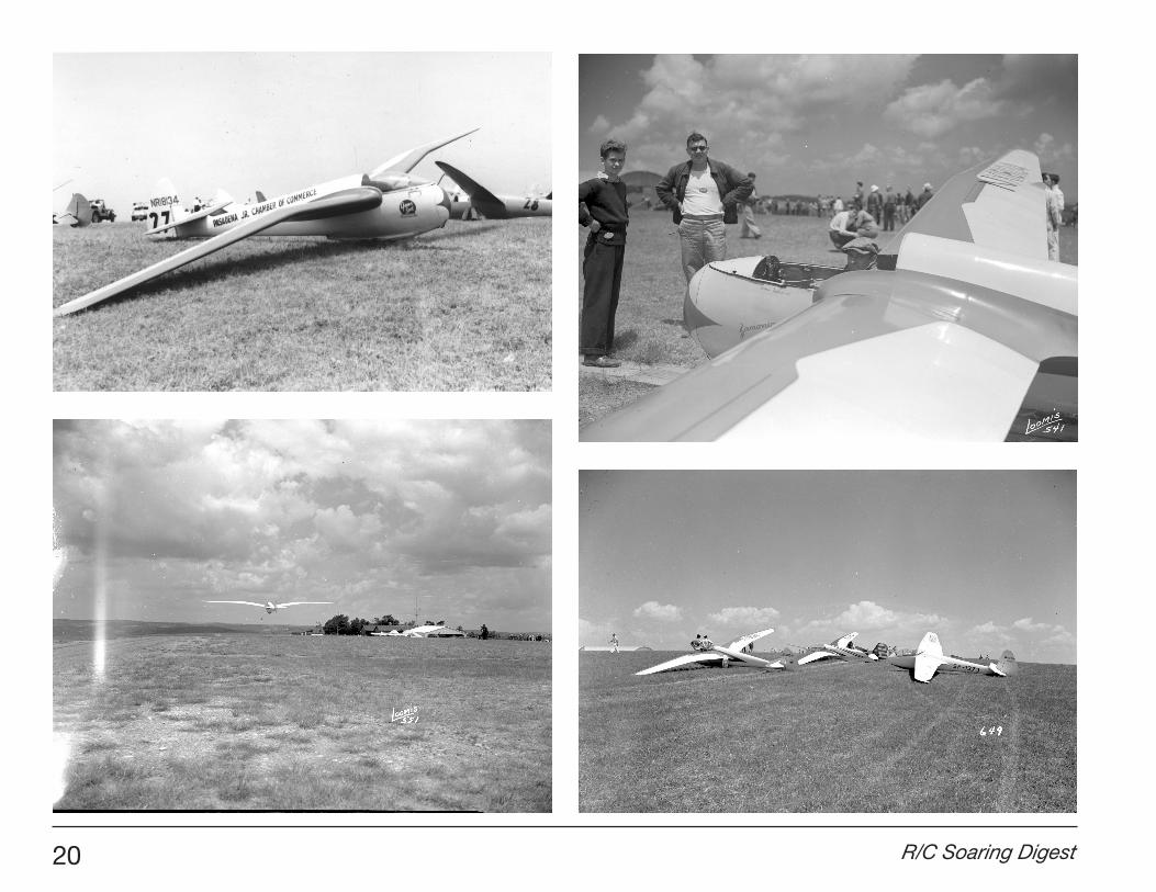
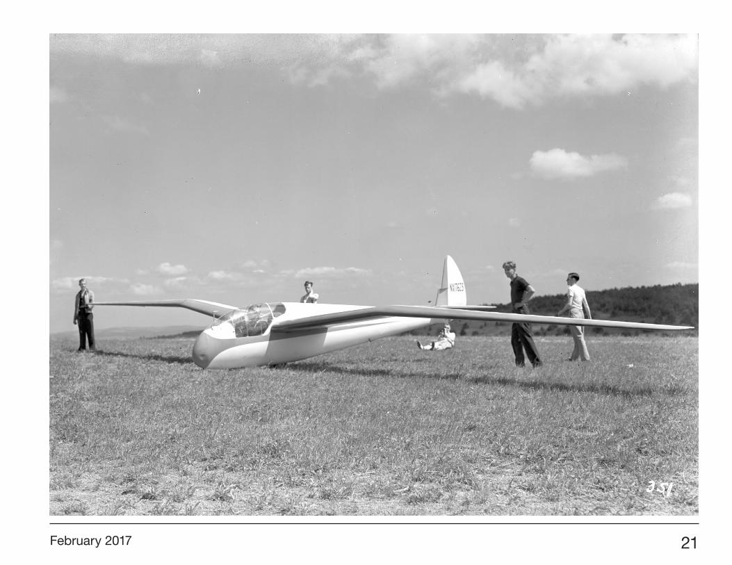
These photos were taken by Fred Loomis, a local Elmira, NY, photographer. Loomis spent the week at the hill, took photos of everyone and everything, developed the film and sold postcards from his tent, shown below, to the many visitors a few hours later. This was his summer income and entertainment.
20 R/C Soaring Digest
February 2017 21
22 R/C Soaring Digest
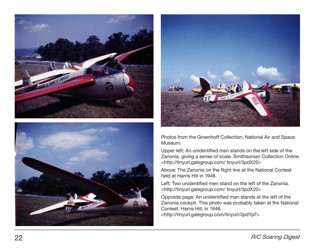
Photos from the Groenhoff Collection, National Air and Space Museum.
Upper left; An unidentified man stands on the left side of the Zanonia, giving a sense of scale. Smithsonian Collection Online. <http://tinyurl.galegroup.com/ tinyurl/3pdX20>
Above: The Zanonia on the flight line at the National Contest held at Harris Hill in 1948.
Left: Two unidentified men stand on the left of the Zanonia. <http://tinyurl.galegroup.com/ tinyurl/3pdX20>
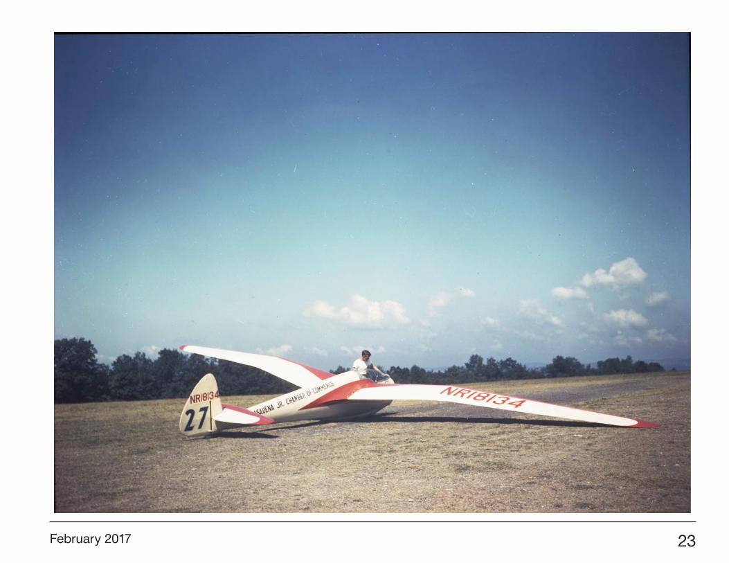
Opposite page: An unidentified man stands at the left of the Zanonia cockpit. This photo was probably taken at the National Contest, Harris Hill, in 1948. <http://tinyurl.galegroup.com/tinyurl/3pdYp7>
February 2017 23
24 R/C Soaring Digest
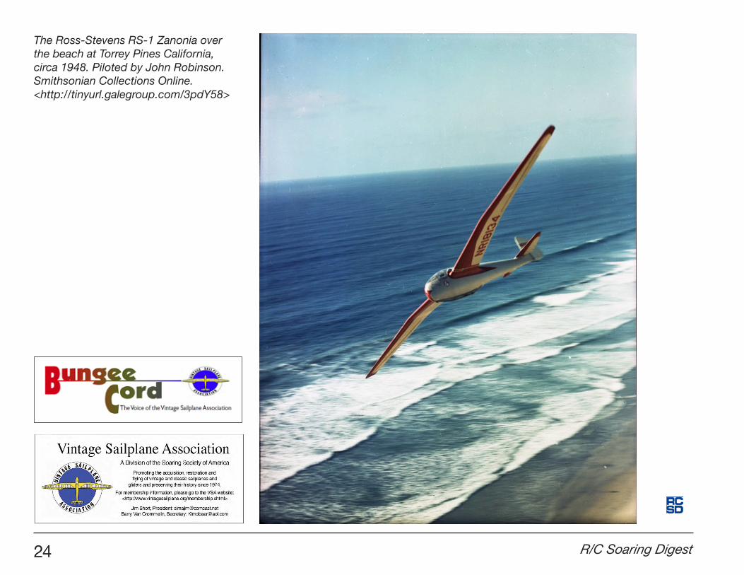
The Ross-Stevens RS-1 Zanonia over the beach at Torrey Pines California, circa 1948. Piloted by John Robinson. Smithsonian Collections Online. <http://tinyurl.galegroup.com/3pdY58>
February 2017 25
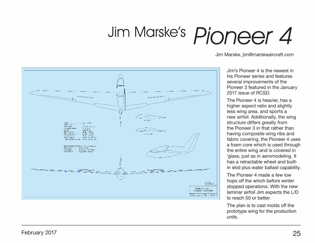
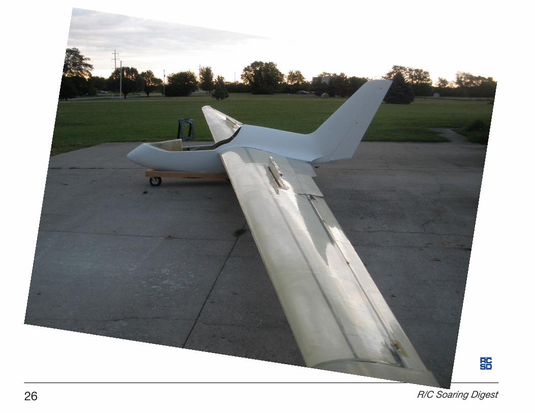
Jim’s Pioneer 4 is the newest in his Pioneer series and features several improvements of the Pioneer 3 featured in the January 2017 issue of RCSD.
The Pioneer 4 is heavier, has a higher aspect ratio and slightly less wing area, and sports a new airfoil. Additionally, the wing structure differs greatly from the Pioneer 3 in that rather than having composite wing ribs and fabric covering, the Pioneer 4 uses a foam core which is used through the entire wing and is covered in ’glass, just as in aeromodeling. It has a retractable wheel and built-in skid plus water ballast capability.The Pioneer 4 made a few low hops off the winch before winter stopped operations. With the new laminar airfoil Jim expects the L/D to reach 50 or better. The plan is to cast molds off the prototype wing for the production units.
Jim Marske’s Pioneer 4Jim Marske, [email protected]
SCALE:DRAWN BY:
P-400J. Marske, 21 Mar 14 1/18
PIONEER 4 -15 TAILLESS SAILPLANE
26 R/C Soaring Digest
February 2017 27
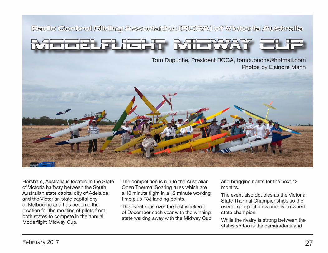
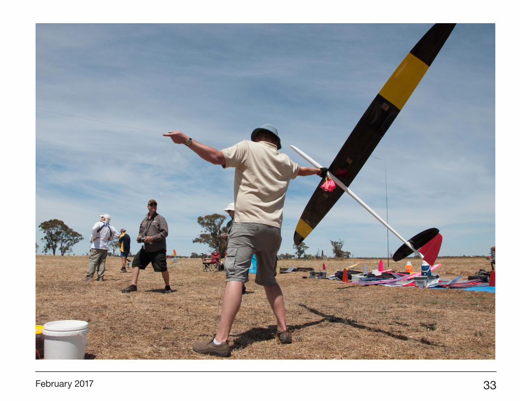
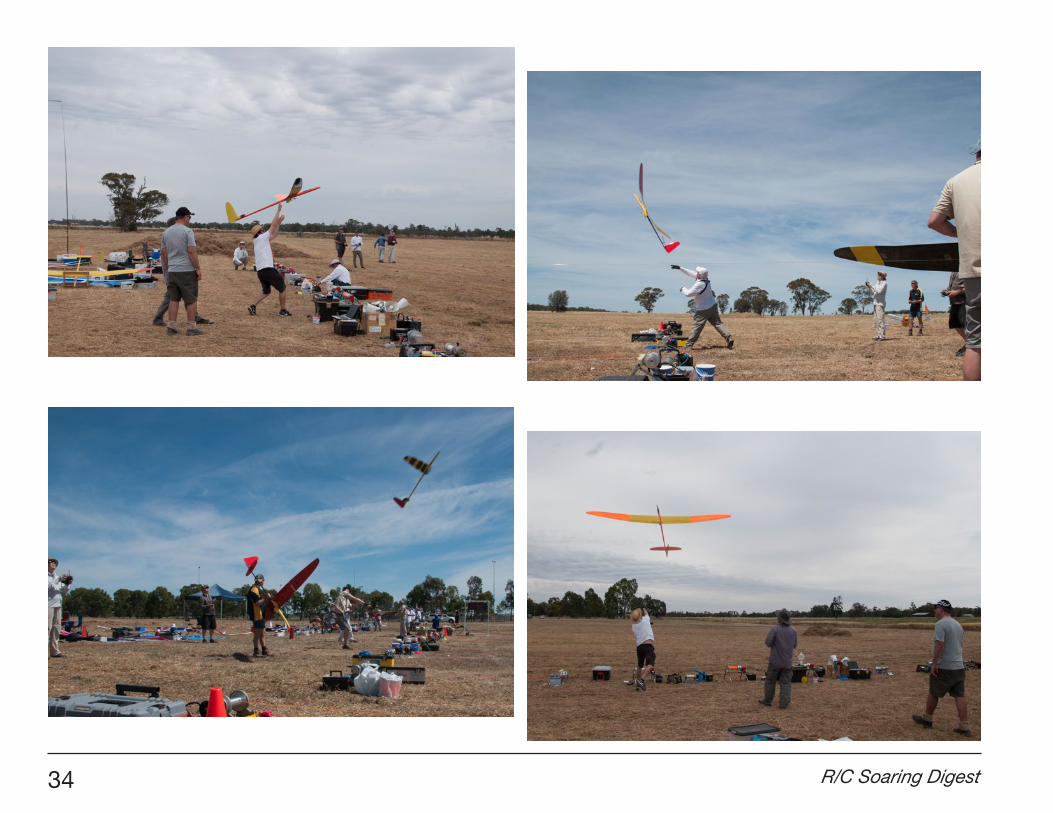
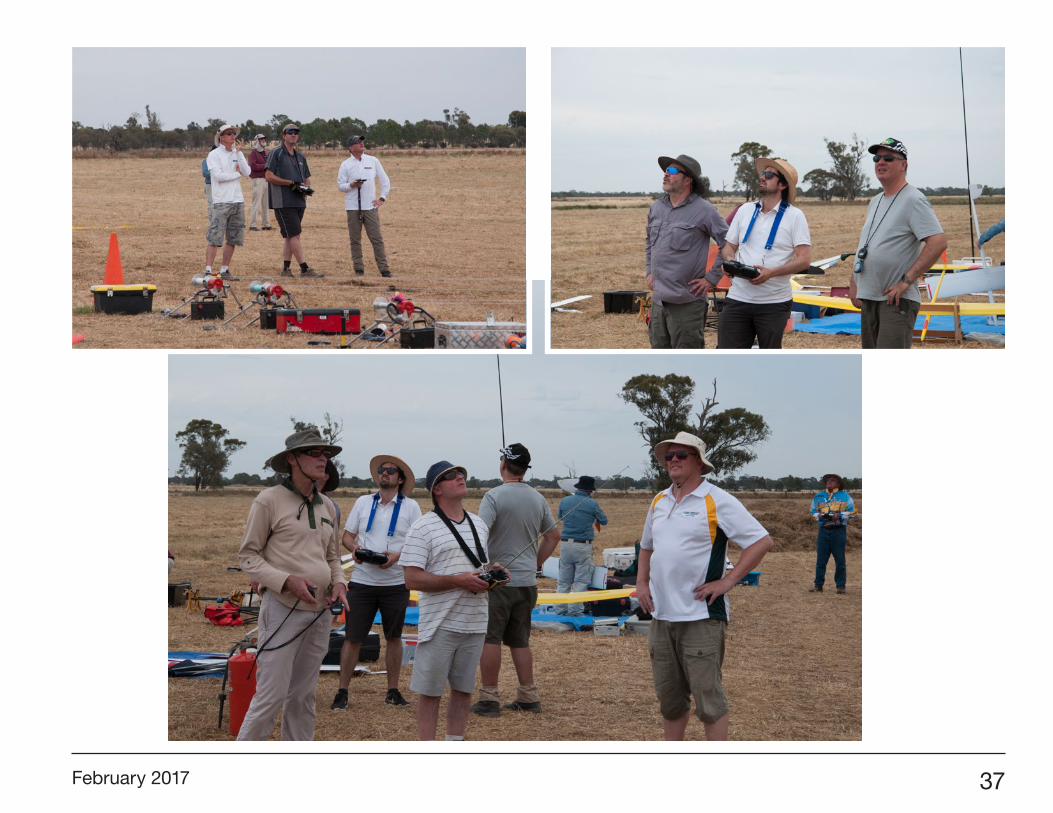
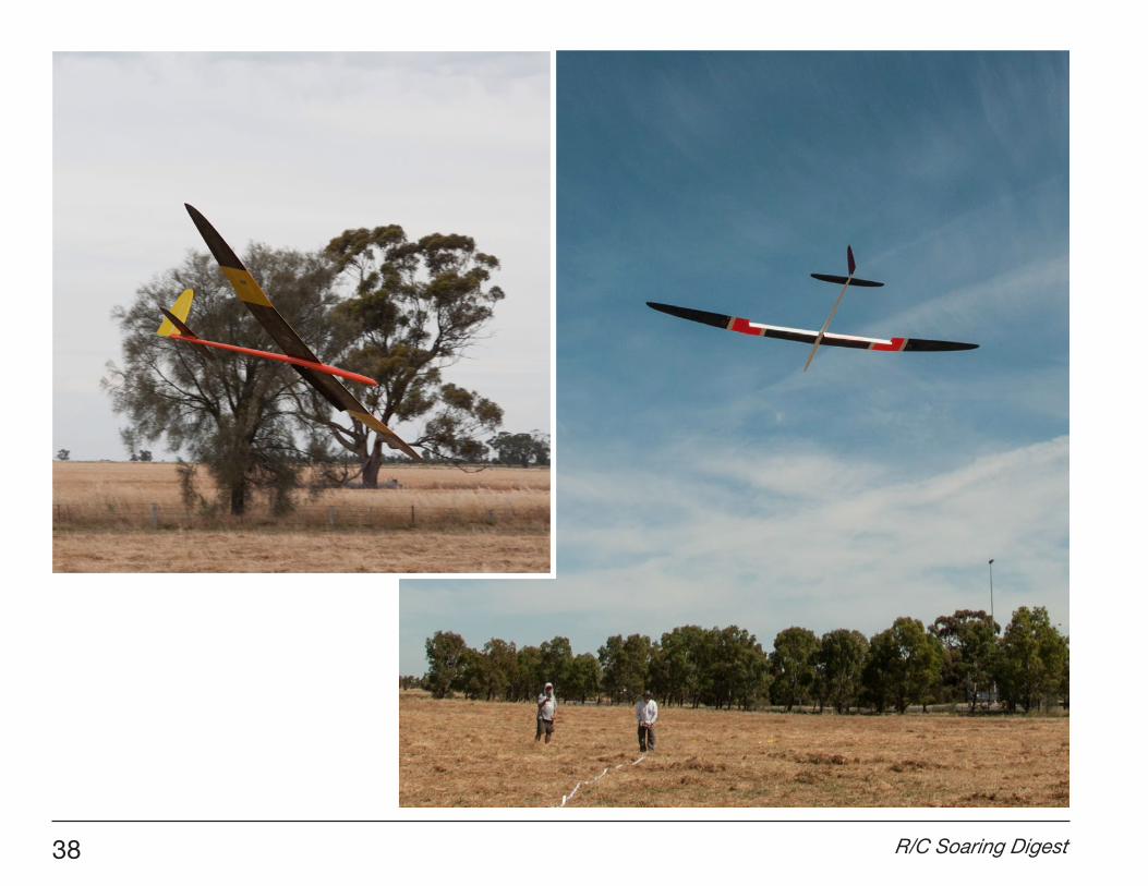
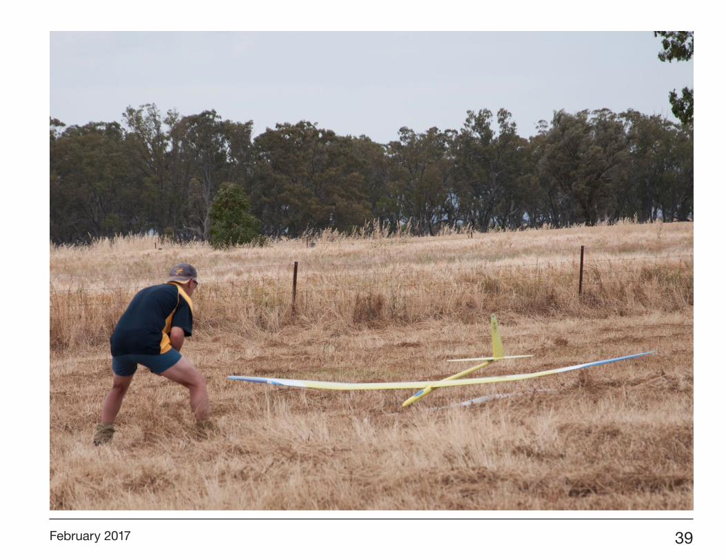
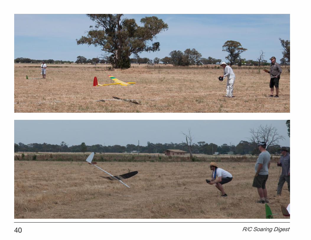
Horsham, Australia is located in the State of Victoria halfway between the South Australian state capital city of Adelaide and the Victorian state capital city of Melbourne and has become the location for the meeting of pilots from both states to compete in the annual Modelflight Midway Cup.
The competition is run to the Australian Open Thermal Soaring rules which are a 10 minute flight in a 12 minute working time plus F3J landing points.
The event runs over the first weekend of December each year with the winning state walking away with the Midway Cup
and bragging rights for the next 12 months.
The event also doubles as the Victoria State Thermal Championships so the overall competition winner is crowned state champion.
While the rivalry is strong between the states so too is the camaraderie and
Modelflight Midway CupRadio Control Gliding Association (RCGA) of Victoria Australia
Tom Dupuche, President RCGA, [email protected] by Elsinore Mann
28 R/C Soaring Digest
each year pilots enjoy heading back to Horsham to swap stories, do lots of flying and see who will emerge as Midway Cup champions.
A huge thank-you to the team at WMAA; Adam, Rolf and Vic for hosting us and providing such great hospitality. Equally a thank-you to the team from Modelflight <http://www.modelflight.com.au/> who sponsored the event and provided the prize pool and event support.
As is the norm, pilots arrived on the Friday and met at The Exchange Hotel for dinner and pilot registration.
The Exchange has now become the regular meeting place to start the South Australia vs Victoria rivalry and this year was no different.
With Victoria leading two wins to zero, South Australia were out to set the record books straight and had great representation with 14 pilots.
Sunday morning and we again started at 8:00 am, but the conditions were very different to Saturday.
The early groups were regularly won with six or seven minute flights and a number of the groups throughout the day proved very difficult.
Positions were mixed up all day and it certainly wasn’t a landing competition and made for some exciting changes to the leaderboard.
Four rounds were flown on the Sunday and there were four different leaders through the day.
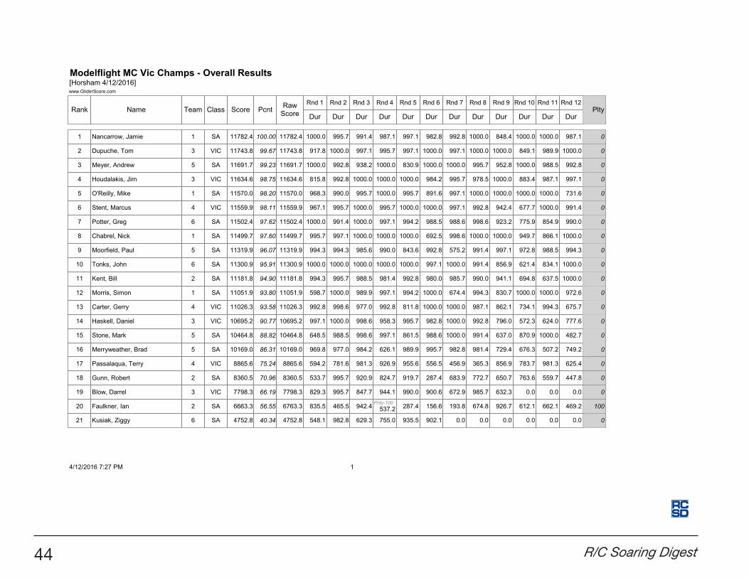
When the dust had settled and 12 rounds were complete it was South Australia who won the Midway Cup for their first time by 105 points - 35,044 to 34,939 (scores of the top three pilots from each state make up the state score) and Jamie Nancarrow who emerged as Victorian State Champion.
Saturday morning and the forecast didn’t disappoint - very little wind and blue skies greeted the pilots as they arrived at the Burnt Creek Road field.
Well organised pilots meant that we got underway just after the planned 8:00 am start. After tricky morning conditions the day turned very thermally and all rounds were won with at least one pilot flying out their time.
Regular downwind launches proved challenging, but with the wind moving around all day there was no option to move the flightline. At the end of day one we had completed eight rounds and the scores were very close. Seconds separated the top few.
Saturday night dinner was at a local public house - the Bull and Mouth Hotel. Good food, good beer and good company meant for a great night.
The event is run by the Radio Control Gliding Association (RCGA) of Victoria
and hosted at the Wimmeria Model Aircraft Association (WMAA) field.
February 2017 29
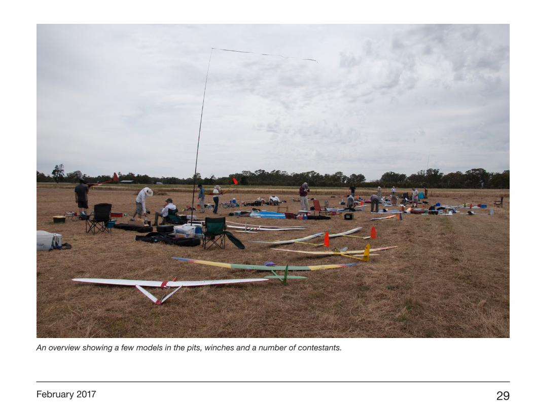
An overview showing a few models in the pits, winches and a number of contestants.
30 R/C Soaring Digest
February 2017 31
32 R/C Soaring Digest
February 2017 33
34 R/C Soaring Digest
February 2017 35
36 R/C Soaring Digest
February 2017 37
38 R/C Soaring Digest
February 2017 39
40 R/C Soaring Digest
February 2017 41
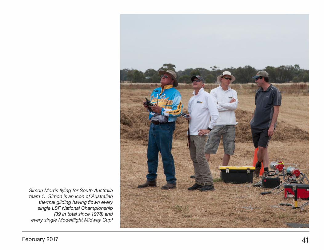
Simon Morris flying for South Australia team 1. Simon is an icon of Australian
thermal gliding having flown every single LSF National Championship
(39 in total since 1978) and every single Modelflight Midway Cup!
42 R/C Soaring Digest
February 2017 43
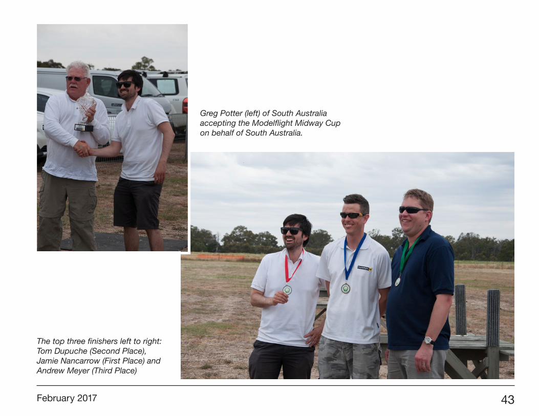
The top three finishers left to right: Tom Dupuche (Second Place), Jamie Nancarrow (First Place) and Andrew Meyer (Third Place)
Greg Potter (left) of South Australia accepting the Modelflight Midway Cup on behalf of South Australia.
44 R/C Soaring Digest
February 2017 45
It’s been several years since we’ve presented our On the ’Wing... column in RC Soaring Digest. This has been primarily due to our inability to make any further progress on our Windlord XC project. Still, we remain focused on the history, current technologies, and potential of tailless aircraft.
We’ve recently run into a couple of publications which definitely deserve sharing with RCSD readers, particularly in light of the recent work by Al Bowers and the NASA PRANDTL-D.
For those needing reminder of the importance of the PRANDTL-D experimental findings, here’s an excerpt from the September 2016 issue of NASA Tech Briefs <http://www.techbriefs.com/component/content/article/ntb/tech-briefs/aerospace/25358>:
“Adverse yaw, present in current aircraft design, is the horizontal movement around a vertical axis of an aircraft in the direction opposite a turn. As an aircraft banks, differential drag creates adverse yaw. Pilots must employ some form of yaw control to counteract this effect. Unfortunately, this yaw control introduces another form of drag that degrades performance. However, a wing with proverse yaw (that is, force in the same direction as the turn) does not need such control and thus helps optimize aircraft efficiency.
On the ’Wing...
Bill & Bunny Kuhlman, [email protected]
Examining Variables Related to the Control of Tailless Aircraft
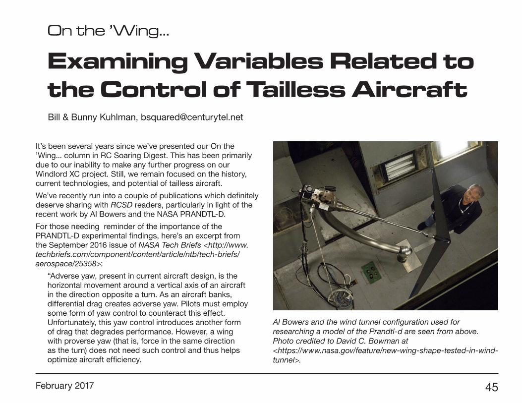
Al Bowers and the wind tunnel configuration used for researching a model of the Prandtl-d are seen from above. Photo credited to David C. Bowman at <https://www.nasa.gov/feature/new-wing-shape-tested-in-wind-tunnel>.
46 R/C Soaring Digest
“The Armstrong team (supported by a large contingent of NASA Aeronautics Academy interns) built upon the 1912 research of the German engineer Ludwig Prandtl to design and validate a scale model of a non-elliptical wing that reduces drag and increases efficiency. Known as the PRANDTL-D wing, this design addresses integrated bending moments and lift to achieve a 12 percent drag reduction. The approach to handling adverse yaw employs fine wing adjustments rather than an aircraft’s vertical tail.
As a proof-of-concept, the PRANDTLD team demonstrated “proverse yaw during a live flight test in June 2013. The remote-controlled aircraft had a bell-shaped spanload and no vertical surfaces of any kind.
“The key to the innovation is reducing the drag of the wing through use of the bell-shaped spanload, as opposed to the conventional elliptical spanload. To achieve the bell spanload, designers used a twisted and sharply tapered wing, with 11 percent less wing area than the comparable elliptical spanload wing. The new wing has 22 percent more span and 11 percent less area, resulting in an immediate 12.5 percent efficiency gain. Furthermore, using twist to achieve the bell spanload produces induced thrust at the wing tips, and this forward thrust increases when lift is increased at the wingtips for roll control. The result is that the aircraft rolls and yaws in the same direction as a turn, eliminating the need for a vertical tail to provide yawing moment. When combined with a blended-wing body, this approach maximizes aerodynamic performance, minimizes weight, and optimizes flight control.”
For we aeromodelers, Al has been kind enough to provide a “thumbnail” of the twist paradigm we can use to construct our own tailless models from designs with no vertical control surface. He posted the following on the Horten Flying Wing Believers FaceBook page:
“Let’s assume for a moment that you want to build an RC model of a flying wing. Like a Horten. But you don’t know how to create the twist. Or maybe you’ve built a few Zagi-like aircraft, and every time you designed something that looked like a Horten it didn’t fly well at all ( if it flew at all). What went wrong?
“The problem is the twist. I spent TWO DECADES figuring this out. There is a precise solution. This isn’t precise. But after looking at the numbers, I think this is close enough.
“A twist approximation
“This will get you close and will give you a BSLD for a model. Some of this is guess-work on my part. But it shouldn’t be too far off.
“I assume you can do basic aero calculations, like lift coefficient and mean aerodynamic chord. I also assume you’re using quite a bit of taper (tip chord is 10% to 50% of the root chord), you’re using moderate sweep (15 deg to 25 deg), and fairly high aspect ratio (at least 6 or higher).
“NEVER NEVER NEVER do this for an aircraft intended to fly a person!!!!! This is a crude approximation to use for a model ONLY!!! If I hear about any one trying to do this for a full size aircraft I will show up at your shop with a saw and cut your mold/wing up into little tiny pieces!!! I don’t ever want a single one of you getting hurt flying something this crude!!!
“First figure out what your design lift coefficient is going to be. This is where your aircraft is going to spend most of its time flying around. Motor aircraft will be somewhat faster (lower CL, like 0.4) than gliders which tend to fly slower (higher CL, like 0.6). This is a critical number, you need to remember this number really well (like your birth date or your wedding anniversary!!!). And I assume you’re using thin symmetric airfoils (or nearly
February 2017 47
so). If you’re using a cambered reflexes airfoil at the centerline that tapers linearly to a symmetric at the tip, you need to offset the twist by the zero lift AOA (this is the aerodynamic twist).
“Second, calculate the total amount of twist you need for your wing. This number is 20 times your design CL. Example: if your glider has a design CL of 0.6 you will need a total twist of 12 degrees.
“Now comes the hard/weird part. You need four control points on your wing along the span. The four control points are:
“At the centerline, 0% span
“At the quarter span, 25% span
“At the half span, 50% span
“At the tip, 100% span
“Now set the twist at the 0% span (centerline) to zero.
“At the 25% span (quarter span) you need your CL in degrees of WASH-IN. Example: our glider example with a design CL of 0.6 has 0.6 degrees of wash-in.
“At the 50% span (half span) you need zero washout.
“At the 100% span (tip) you need 20 times your design CL in degrees of washout. Example: our glider example with a design CL of 0.6 has 12 degrees of washout.
“Now plot this on a piece of graph paper and get a French curve (I know, that’s very old-school and antiquated) and draw a curve through those points. That’s your twist you need for a BSLD. If you’re fancy with a computer you can draw a cubic-spline through those points and get your twist curve.
“To build, you can twist your building board or use a curved foam board jig to build on. Or you can make a series of wedges with an inverse twist and hot wire the wing (when you release the foam from the inverse twist,
the foam will spring back and have the correct twist). Or you can cut a big fancy mold and lay up skins and build in the mold bed.
“Make sure your elevons are all in the last 25-30% of the span out towards the tips. Also remember that the elevons needs to have straight hinge lines! Otherwise you won’t be able to deflect your elevons.
“After you get your model built start out with your CG way far forward, maybe set to 10% cmac. As you test fly, move the CG until your trim needed for level flight is with no elevon deflection.
“Enjoy your BSLD aircraft! Let us know how well this works, and post pictures. A month from now there had better be dozens of baby Hortens flying around!”
While we’re talking about overcoming adverse yaw in tailless aircraft, the question arises as to how to overcome this tendency when not using a bell-shaped lift distribution.
In the past, there have been a wide variety of mechanical and aerodynamic techniques designed to overcome adverse yaw while banking. These have included split flaps at the wing tips, as seen on the Northrop B-2 “Spirit,” projecting rods extending from the wing tips, and differential deflection of inboard and outboard control surfaces.
The latter requires a rather complicated mechanical control system, as the movement of two or more surfaces on one wing varies depending on whether the commanded action is to pitch the nose up or down and/or roll the aircraft.
These complicated mechanical control setups were actually used on several Horten designs and have been used effectively on a few models as well. Modern computer systems can be used to alleviate the mechanical complications in both full size and model aircraft.
In light of these technical electronic advances, research is still being concentrated on differential control surface deflection to
48 R/C Soaring Digest
overcome adverse yaw. One of the latest of these research projects is being done at KTH Royal Institute of Technology <https://www.kth.se/en> in Stockholm, Sweden, as noted in the latest edition of the T.W.I.T.T. Newsletter.
Here’s the text from the KTH “Control of Tailless Aircraft,” along with the associated photos:
“Researchers“Glora Stenfeldt, M.Sc.“Prof. Ulf Ringertz
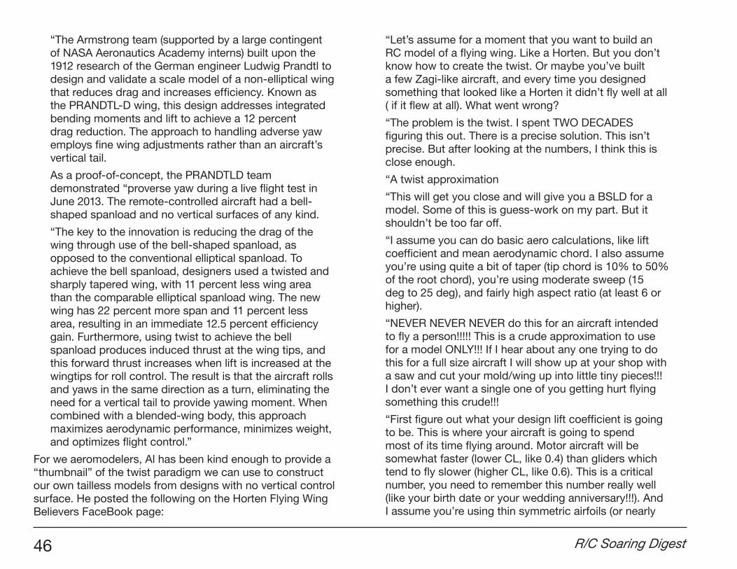
“Flying wings, or tailless aircraft, can be designed to have very low radar signature. The particular shape, and especially the absence of a vertical tail, require rather unconventional concepts to ensure that the aircraft is laterally controllable in all flight conditions.
“A common approach to generate yaw control moments without a vertical fin is to create asymmetric drag by means of differential flap deflections, that is, by deflecting two flaps on only one wing in opposite directions. In contrast to a conventional rudder deflection, the resulting yaw moment is not linearly dependent on the deflection angle. Furthermore, the efficiency of this technique depends substantially on the flight condition, notably the angle of attack.
Wind tunnel model displaying a differential flap deflection.
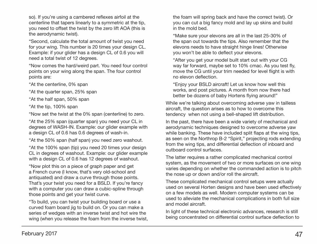
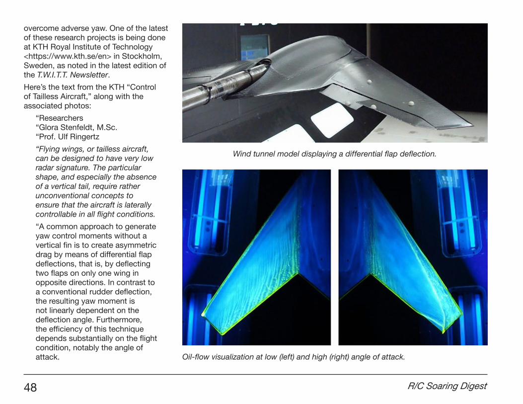
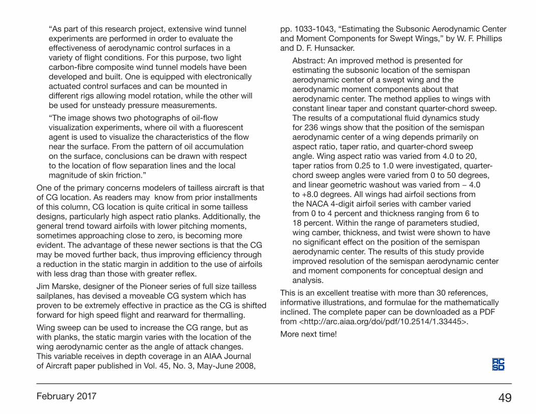
Oil-flow visualization at low (left) and high (right) angle of attack.
February 2017 49
“As part of this research project, extensive wind tunnel experiments are performed in order to evaluate the effectiveness of aerodynamic control surfaces in a variety of flight conditions. For this purpose, two light carbon-fibre composite wind tunnel models have been developed and built. One is equipped with electronically actuated control surfaces and can be mounted in different rigs allowing model rotation, while the other will be used for unsteady pressure measurements.
“The image shows two photographs of oil-flow visualization experiments, where oil with a fluorescent agent is used to visualize the characteristics of the flow near the surface. From the pattern of oil accumulation on the surface, conclusions can be drawn with respect to the location of flow separation lines and the local magnitude of skin friction.”
One of the primary concerns modelers of tailless aircraft is that of CG location. As readers may know from prior installments of this column, CG location is quite critical in some tailless designs, particularly high aspect ratio planks. Additionally, the general trend toward airfoils with lower pitching moments, sometimes approaching close to zero, is becoming more evident. The advantage of these newer sections is that the CG may be moved further back, thus improving efficiency through a reduction in the static margin in addition to the use of airfoils with less drag than those with greater reflex.
Jim Marske, designer of the Pioneer series of full size tailless sailplanes, has devised a moveable CG system which has proven to be extremely effective in practice as the CG is shifted forward for high speed flight and rearward for thermalling.
Wing sweep can be used to increase the CG range, but as with planks, the static margin varies with the location of the wing aerodynamic center as the angle of attack changes. This variable receives in depth coverage in an AIAA Journal of Aircraft paper published in Vol. 45, No. 3, May-June 2008,
pp. 1033-1043, “Estimating the Subsonic Aerodynamic Center and Moment Components for Swept Wings,” by W. F. Phillips and D. F. Hunsacker.
Abstract: An improved method is presented for estimating the subsonic location of the semispan aerodynamic center of a swept wing and the aerodynamic moment components about that aerodynamic center. The method applies to wings with constant linear taper and constant quarter-chord sweep. The results of a computational fluid dynamics study for 236 wings show that the position of the semispan aerodynamic center of a wing depends primarily on aspect ratio, taper ratio, and quarter-chord sweep angle. Wing aspect ratio was varied from 4.0 to 20, taper ratios from 0.25 to 1.0 were investigated, quarter-chord sweep angles were varied from 0 to 50 degrees, and linear geometric washout was varied from − 4.0 to +8.0 degrees. All wings had airfoil sections from the NACA 4-digit airfoil series with camber varied from 0 to 4 percent and thickness ranging from 6 to 18 percent. Within the range of parameters studied, wing camber, thickness, and twist were shown to have no significant effect on the position of the semispan aerodynamic center. The results of this study provide improved resolution of the semispan aerodynamic center and moment components for conceptual design and analysis.
This is an excellent treatise with more than 30 references, informative illustrations, and formulae for the mathematically inclined. The complete paper can be downloaded as a PDF from <http://arc.aiaa.org/doi/pdf/10.2514/1.33445>.
More next time!