Embed Size (px)
Citation preview
SoaringDigestRadio C ntrolled
December 2016 Vol. 33, No. 12
2 R/C Soaring Digest
December 2016
Vol. 33, No. 12C
ON
TEN
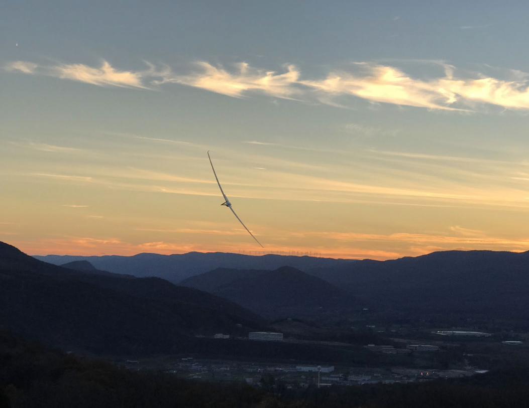
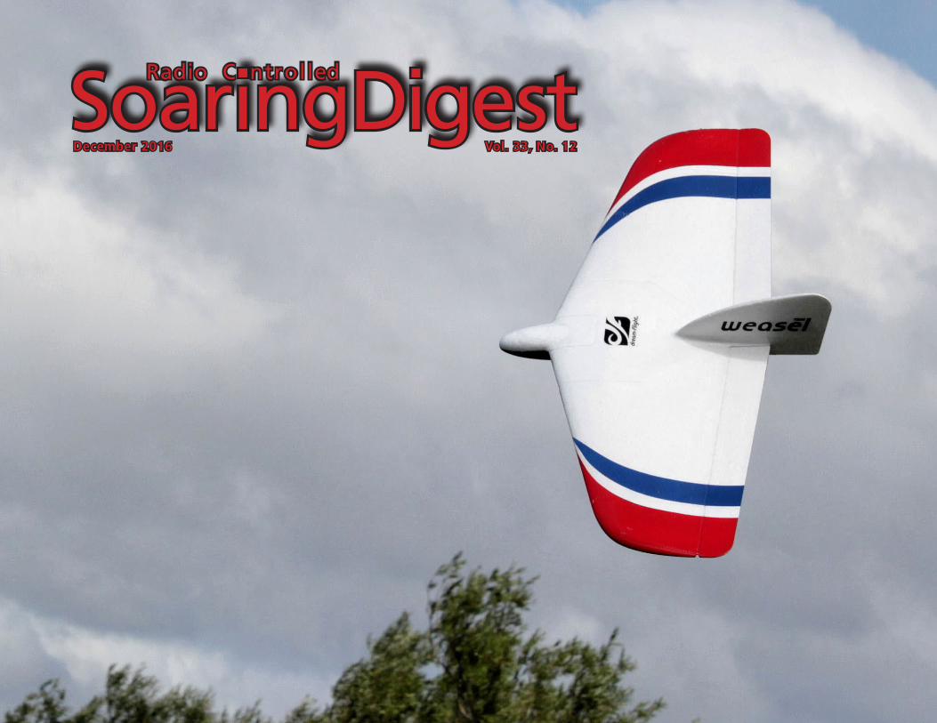
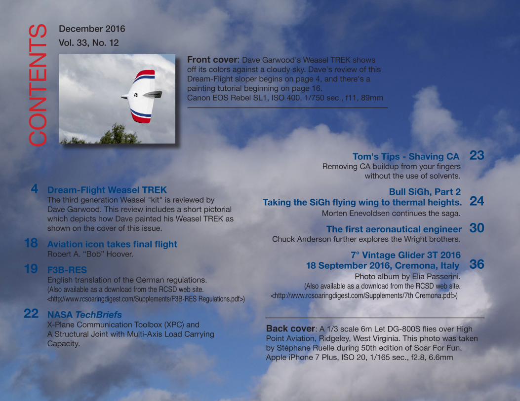
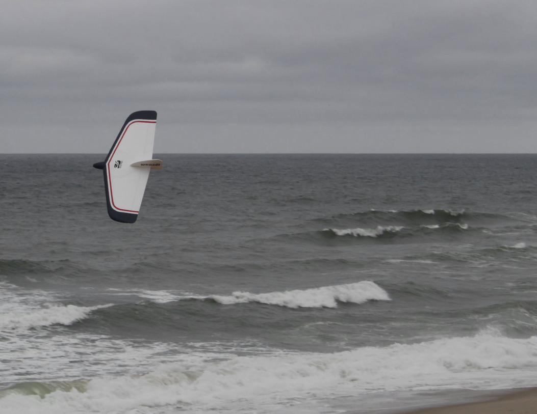
TSFront cover: Dave Garwood's Weasel TREK shows off its colors against a cloudy sky. Dave's review of this Dream-Flight sloper begins on page 4, and there's a painting tutorial beginning on page 16. Canon EOS Rebel SL1, ISO 400, 1/750 sec., f11, 89mm
4 Dream-Flight Weasel TREK The third generation Weasel "kit" is reviewed by Dave Garwood. This review includes a short pictorial which depicts how Dave painted his Weasel TREK as shown on the cover of this issue.
18 Aviation icon takes final flightRobert A. “Bob” Hoover.
19 F3B-RES English translation of the German regulations. (Also available as a download from the RCSD web site.<http://www.rcsoaringdigest.com/Supplements/F3B-RES Regulations.pdf>)
22 NASA TechBriefsX-Plane Communication Toolbox (XPC) and A Structural Joint with Multi-Axis Load Carrying Capacity.
Tom's Tips - Shaving CA 23Removing CA buildup from your fingers
without the use of solvents.
Bull SiGh, Part 2Taking the SiGh flying wing to thermal heights. 24
Morten Enevoldsen continues the saga.
The first aeronautical engineer 30Chuck Anderson further explores the Wright brothers.
7° Vintage Glider 3T 2016 18 September 2016, Cremona, Italy 36
Photo album by Elia Passerini.(Also available as a download from the RCSD web site.
<http://www.rcsoaringdigest.com/Supplements/7th Cremona.pdf>)
Back cover: A 1/3 scale 6m Let DG-800S flies over High Point Aviation, Ridgeley, West Virginia. This photo was taken by Stéphane Ruelle during 50th edition of Soar For Fun. Apple iPhone 7 Plus, ISO 20, 1/165 sec., f2.8, 6.6mm
December 2016 3
In the AirR/C Soaring Digest
December 2016Volume 33 Number 12
Managing Editors, Publishers Bill & Bunny (B2) Kuhlman
Contact [email protected]://www.rcsoaringdigest.comYahoo! group: RCSoaringDigest
FaceBook: https://www.facebook.com/RCSoaringDigest
R/C Soaring Digest (RCSD) is a reader-written monthly publication for the R/C sailplane enthusiast and has been published since January 1984. It is dedicated to sharing technical and educational information. All material contributed must be original and not infringe upon the copyrights of others. It is the policy of RCSD to provide accurate information. Please let us know of any error that significantly affects the meaning of a story. Because we encourage new ideas, the content of each article is the opinion of the author and may not necessarily reflect those of RCSD. We encourage anyone who wishes to obtain additional information
to contact the author.
———
Copyright © 2016 R/C Soaring DigestPublished by B2Streamlines
http://www.b2streamlines.comP.O. Box 975, Olalla WA 98359
All rights reserved
———
RC Soaring Digest is published using Adobe InDesign CS6
Welcome to the December 2016 edition of RC Soaring Digest!
A rather diverse selection of materials populate the RCSD pages this month: a Weasel TREK review, F3B-RES regulations, a couple of articles from the National Aeronautics and Space Administration, another tip from the workshop of Tom Broeski, a follow-up on the Bull SiGh article which appeared in RCSD back in 2014, some further information on the Wright brothers, a vintage photo album, and an obituary. Should be worthwhile reading for any RC soaring enthusiast.
Within the Christmas and Gift-Giving List offered last month was a recommendation for the X-Plane software package. As a reminder, X-Plane is a flight simulator package which can utilize pre-made aircraft files and which also allows the user to develop their own aircraft, both model and full size. One of the latest issues of NASA TechBriefs included an announcement of a software add-on for X-Plane, the X-Plane Communication Toolbox (XPC). This research tool has been used to visualize flight paths, test control algorithms, simulate an active airspace, or generate out-the-window visuals for in-house flight simulation software. Possible applications include active control of an XPlane simulation, flight visualization, recording states during a flight, or interacting with a mission over UDP. The XPC package was developed at Ames Research Center and the software is now available for use at no cost. To request a copy, simply visit <https://software.nasa.gov/software/ARC-17185-1>. XPC is compatible with X-Plane 9 or 10 (Linux, Mac OS X and Windows are available ).
Time to build another sailplane!
4 R/C Soaring Digest
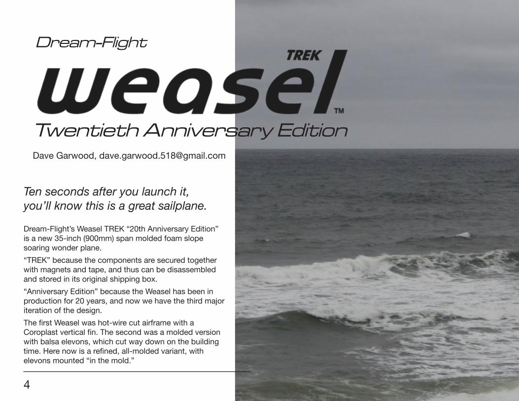
Ten seconds after you launch it, you’ll know this is a great sailplane.
Dream-Flight’s Weasel TREK “20th Anniversary Edition” is a new 35-inch (900mm) span molded foam slope soaring wonder plane.
“TREK” because the components are secured together with magnets and tape, and thus can be disassembled and stored in its original shipping box.
“Anniversary Edition” because the Weasel has been in production for 20 years, and now we have the third major iteration of the design.
The first Weasel was hot-wire cut airframe with a Coroplast vertical fin. The second was a molded version with balsa elevons, which cut way down on the building time. Here now is a refined, all-molded variant, with elevons mounted “in the mold.”
4
Dream-Flight
Twentieth Anniversary Edition Dave Garwood, [email protected]
December 2016 5
6 R/C Soaring Digest
BRIEF AIRFRAME ASSEMBLYI’ve read this phrase many times: “Open the box and shake the parts out and the Weasel TREK practically assembles itself.” Everyone I have talked to is utterly happy with the Dream-Flight on-board components kit. Control surface setup is covered in detail in the excellent instruction manual.
BRIEF FLIGHT CHARACTERISTICS In the words of slope pilot Mark Wood, “This is a completely different plane in its responsiveness and the control that the pilot can achieve. Ten seconds after launch you KNOW this is a huge
improvement over earlier models. Set it up EXACTLY per the directions. Mine flew perfectly right out of hand. Inverted loops are a non-event as is simple inverted flight. I’m in love.”
Michael Richter and George Rodriguez, of Dream-Flight were test flying the first-out of-the-mold new Weasel TREKs. George told me, “It was the first session we got to fly the parts out of the mold. It was ripping 20+ MPH and we were carving in close and fast. Really zooming all over each other. A pure Weasel expression session. For me it was my first real bonding moment with the design.”
Michael quoted George as saying the new plane is “The slope model that satisfies the inner fighter pilot kid in all of us. The way it tracks and the ability to zoom around, get away with stuff and not get into trouble too much”.
BRIEF CONCLUSIONThe Weasel TREK is a fabulous slope sailplane. It assembles quicker, builds lighter, and flys more responsively than all previous version Weasels. It is a complete joy to fly. Order one. Fly it. Be happy.
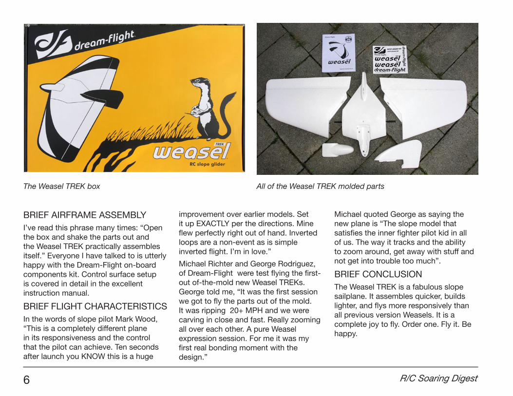
The Weasel TREK box All of the Weasel TREK molded parts
December 2016 7
For confirmed Weasel fans, this is all you need to know. For newcomers to Dream-Flight and the Weasel, more detail follows.
DISCLAIMERI have flown with Michael Richter, designer of Weasel, Alula, and Libelle sailplanes, and I consider him a personal friend. I have greatly admired his manifold design skills and engineering inventiveness ever since I first built and flew his Weasel and Alula slope soaring sailplanes several years ago.
My respect for Michael notches up yet again with the release of the Weasel TREK, because his ingenious refinements in the design have resulted in an even more impressive sailplane. Designers that work to refine an already admired and successful design are rare and wonderful.
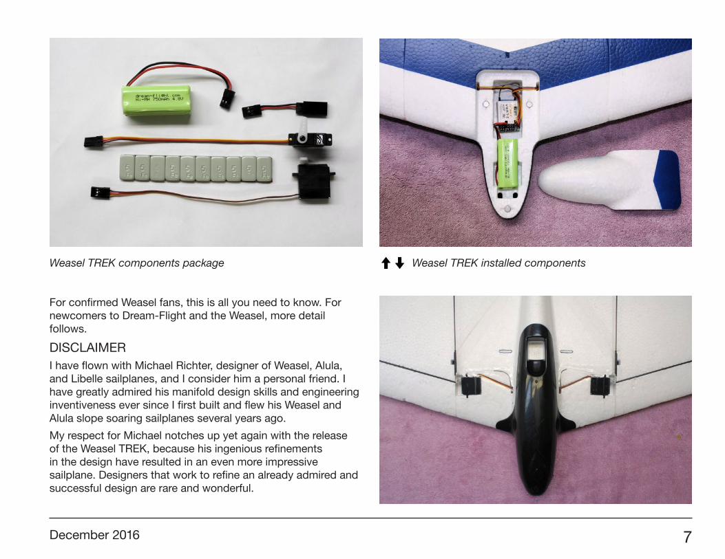
Weasel TREK components package Weasel TREK installed components
8 R/C Soaring Digest
KIT CONTENTS and ASSEMBLY
The molded foam parts have a much smoother surface finish than the molded Weasel-Evo, and mold-injection marks are absent. The wing mount magnets and the elevon control horns are installed at the factory. The elevons are now molded foam, already hinged, and not needing iron-on covering like earlier balsa elevons. A 100% complete hardware kit is included.
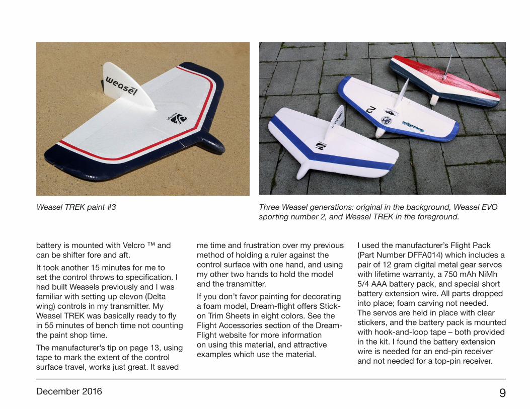
The manufacturer claims one-hour assembly and radio setup time. I’ve completed three builds, each in well under an hour. No glue is used, only magnets and tape. The Weasel TREK is truly designed to disassemble easily to fit back into its original shipping box for ease of storage and safety in transport.
The instruction manual is complete, well organized, and well-illustrated. It’s the best in the business in my estimation. It includes a detailed control surface deflection setup method. Save yourself
some frustration on first-flight day and follow this procedure exactly. You will need a transmitter capable of “Delta wing mixing and adjustable throws/travel.”
I assembled the airframe, and painted the two color upper side markings in two evenings, letting them dry overnight, and painted the underside stripes in a third evening. On the fourth evening installed the servos, receiver, battery pack, and control linkages in 40 minutes. My plane balanced easily on the molded balancing marks with no added weight, as the
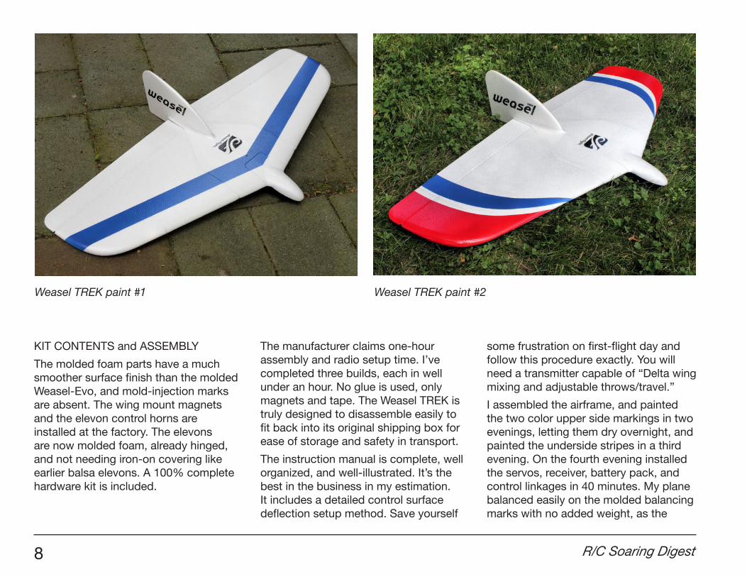
Weasel TREK paint #1 Weasel TREK paint #2
December 2016 9
battery is mounted with Velcro ™ and can be shifter fore and aft.
It took another 15 minutes for me to set the control throws to specification. I had built Weasels previously and I was familiar with setting up elevon (Delta wing) controls in my transmitter. My Weasel TREK was basically ready to fly in 55 minutes of bench time not counting the paint shop time.
The manufacturer’s tip on page 13, using tape to mark the extent of the control surface travel, works just great. It saved
me time and frustration over my previous method of holding a ruler against the control surface with one hand, and using my other two hands to hold the model and the transmitter.
If you don’t favor painting for decorating a foam model, Dream-flight offers Stick-on Trim Sheets in eight colors. See the Flight Accessories section of the Dream-Flight website for more information on using this material, and attractive examples which use the material.
I used the manufacturer’s Flight Pack (Part Number DFFA014) which includes a pair of 12 gram digital metal gear servos with lifetime warranty, a 750 mAh NiMh 5/4 AAA battery pack, and special short battery extension wire. All parts dropped into place; foam carving not needed. The servos are held in place with clear stickers, and the battery pack is mounted with hook-and-loop tape – both provided in the kit. I found the battery extension wire is needed for an end-pin receiver and not needed for a top-pin receiver.
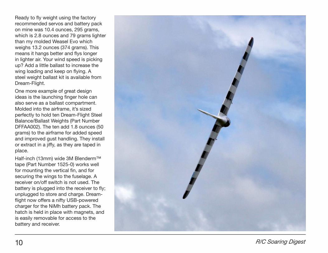
Weasel TREK paint #3 Three Weasel generations: original in the background, Weasel EVO sporting number 2, and Weasel TREK in the foreground.
10 R/C Soaring Digest
Ready to fly weight using the factory recommended servos and battery pack on mine was 10.4 ounces, 295 grams, which is 2.8 ounces and 79 grams lighter than my molded Weasel Evo which weighs 13.2 ounces (374 grams). This means it hangs better and flys longer in lighter air. Your wind speed is picking up? Add a little ballast to increase the wing loading and keep on flying. A steel weight ballast kit is available from Dream-Flight.
One more example of great design ideas is the launching finger hole can also serve as a ballast compartment. Molded into the airframe, it’s sized perfectly to hold ten Dream-Flight Steel Balance/Ballast Weights (Part Number DFFAA002). The ten add 1.8 ounces (50 grams) to the airframe for added speed and improved gust handling. They install or extract in a jiffy, as they are taped in place.
Half-inch (13mm) wide 3M Blenderm™ tape (Part Number 1525-0) works well for mounting the vertical fin, and for securing the wings to the fuselage. A receiver on/off switch is not used. The battery is plugged into the receiver to fly; unplugged to store and charge. Dream-flight now offers a nifty USB-powered charger for the NiMh battery pack. The hatch is held in place with magnets, and is easily removable for access to the battery and receiver.
December 2016 11
For a more complete list of enhancements, download the PDF document, “Designer’s Notes: Improvements of the Weasel-TREK.” It describes the engineering, explains the improvements, and gives insight into the mind of a designer.
SERVO WARRANTY
Dream-Flight now offers “Fly Forever Lifetime Warranty” for their metal gear servos. As I understand it, if one of their metal gear servos mounted in one of their sailplanes suffers stripped gears, Dream-Flight will replace it for free.
FLIGHT REPORT
Over more than ten years of flying Weasels and watching others fly them. I cannot remember a single untoward remark or a complaint about their flight performance (once balance is correct and control surface deflections are set up correctly). Not one. This one is even better.
Indeed, how many sailplane designs have their own one-design annual fly in, like the Weasel Fest? Weasel Festivals have been held in two states (California and Wisconsin) and in two countries (USA and Israel).
I have seen some unhappy faces of slope pilots chasing a galloping Weasel down the ridge because elevator control throw was set too high. You have been warned.
12 R/C Soaring Digest
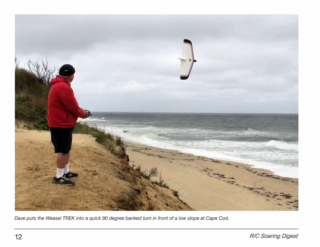
Dave puts the Weasel TREK into a quick 90 degree banked turn in front of a low slope at Cape Cod.
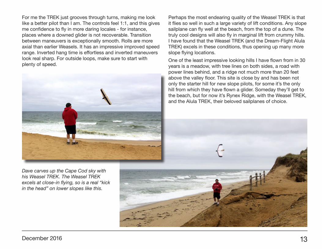
December 2016 13
For me the TREK just grooves through turns, making me look like a better pilot than I am. The controls feel 1:1, and this gives me confidence to fly in more daring locales - for instance, places where a downed glider is not recoverable. Transition between maneuvers is exceptionally smooth. Rolls are more axial than earlier Weasels. It has an impressive improved speed range. Inverted hang time is effortless and inverted maneuvers look real sharp. For outside loops, make sure to start with plenty of speed.
Perhaps the most endearing quality of the Weasel TREK is that it flies so well in such a large variety of lift conditions. Any slope sailplane can fly well at the beach, from the top of a dune. The truly cool designs will also fly in marginal lift from crummy hills. I have found that the Weasel TREK (and the Dream-Flight Alula TREK) excels in these conditions, thus opening up many more slope flying locations.
One of the least impressive looking hills I have flown from in 30 years is a meadow, with tree lines on both sides, a road with power lines behind, and a ridge not much more than 20 feet above the valley floor. This site is close by and has been not only the starter hill for new slope pilots, for some it’s the only hill from which they have flown a glider. Someday they’ll get to the beach, but for now it’s Rynex Ridge, with the Weasel TREK, and the Alula TREK, their beloved sailplanes of choice.
Dave carves up the Cape Cod sky with his Weasel TREK. The Weasel TREK excels at close-in flying, so is a real “kick in the head” on lower slopes like this.
14 R/C Soaring Digest
One more characteristic that makes the Weasel TREK suitable as a starter sailplane is its compact Delta planform shape. The short nose will withstand a “one point landing” better than longer-nose sailplanes. The short-span delta wings will tumble through a cartwheel landing so much better than longer-wing sailplanes. The light weight of the airframe reduces the inertia that must be dispersed in a crash and results in less damage. The airframe is tough enough to land in the bushes on a heavily wooded slope flying site where large landing zones are not available. When there is airframe damage, it can often be repaired with foam-safe glue such as Beacon Foam-Tac.
CONCLUSION
This is a wonderful and magical slope sailplane. It is one of the very rare designs which is tough enough and flies predictably enough to be recommended as a first sailplane for the beginning slope pilot, AND it holds the interest of experienced R/C slope pilots. The Weasel TREK is an advanced version of an already marvelous slope glider, superbly designed and exquisitely manufactured. The Weasel TREK is an RC pilot maker. I say, “Don’t leave home without it.”
WEASEL TREK SPECIFICATIONS
MODEL TYPE Highly maneuverable aerobatic slope sailplaneWINGSPAN 900 mm (35.4 inches)WING AREA 23.42 dm2 (363 square inches)WEIGHT 312-395 gm (11.5-14 ounces)WING LOADING 13.3-16.9 gm/dm2 (4.6-5.6 oz/ft2)CONTROLS 2 channels (elevons)ASSEMBLY TIME Less than an hourFLIGHT WIND SPEED 3-12 m/s (7-25 mph)KIT COST US $100BATTERY PACK, SERVOS US $61.5010 STEEL WEIGHTS KIT US $4.50
ADDITIONAL INFORMATION RESOURCES
Dream-Flight (Weasel TREK kit supplier):http://www.dream-flight.com
Weasel TREK build thread on RC Groups:http://www.rcgroups.com/forums/showthread.php?t=2509327
Promotional Flyer for Weasel-TREK:http://cdn.shopify.com/s/files/1/0263/8893/files/WeaselTREK.pdf?9779618818323794559
Designer’s Notes: Improvements of the Weasel-TREK: http://cdn.shopify.com/s/files/1/0263/8893/files/WeaselTREK_Improvements.pdf?9779618818323794559
Mark Wood’s flight performance quote in context:http://www.rcgroups.com/forums/showpost.php?p=35059027&postcount=142
Beacon Foam-Tac foam safe glue:http://foam-tac.com
WeaselFest threads on RC Groups:WeaselFest 2016: http://www.rcgroups.com/forums/showthread.php?t=2537443WeaselFest 2015: http://www.rcgroups.com/forums/showthread.php?t=2320558WeaselFest 2007: http://www.rcgroups.com/forums/showthread.php?t=620564
December 2016 15
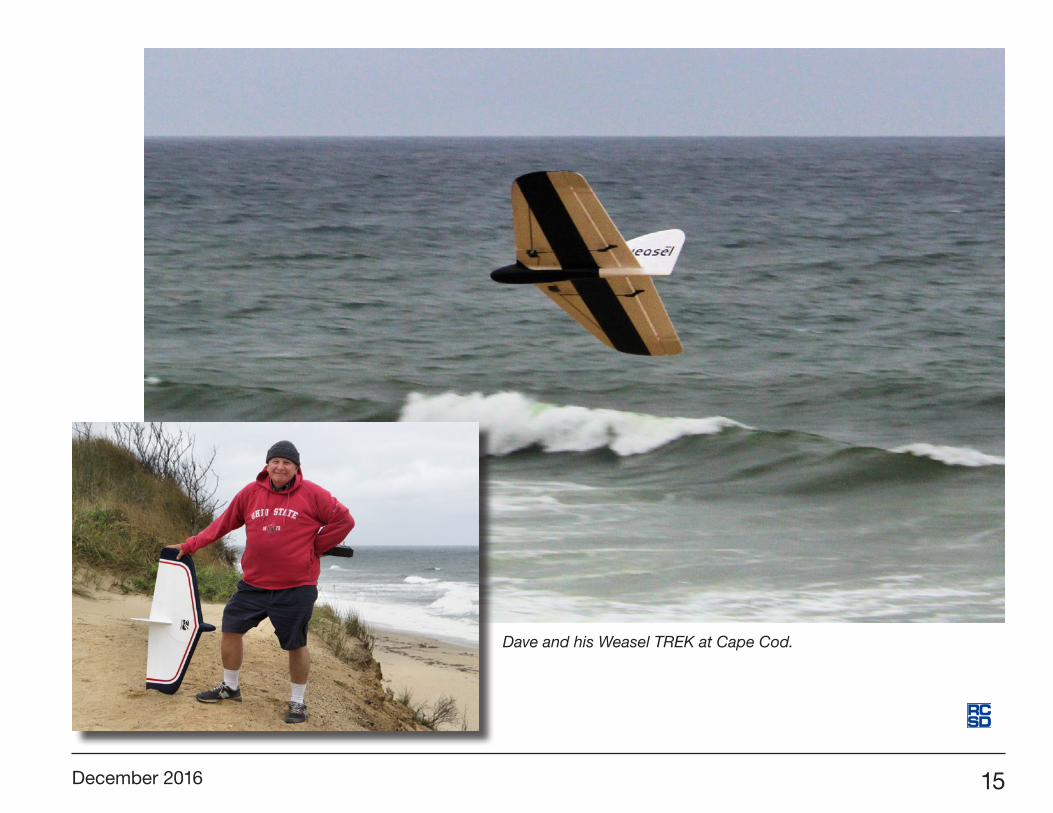
Dave and his Weasel TREK at Cape Cod.
16 R/C Soaring Digest
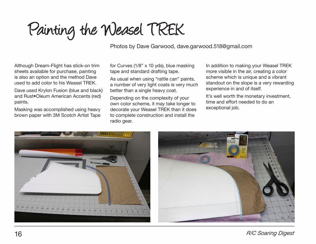
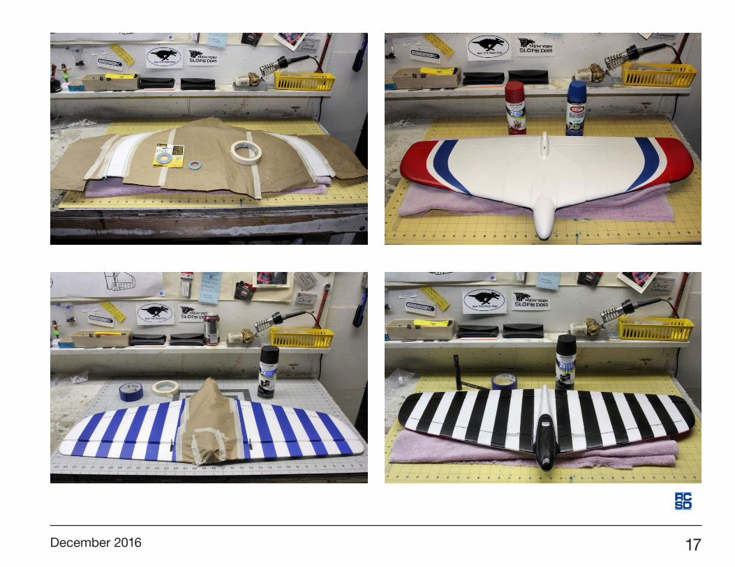
Although Dream-Flight has stick-on trim sheets available for purchase, painting is also an option and the method Dave used to add color to his Weasel TREK.
Dave used Krylon Fusion (blue and black) and Rust•Oleum American Accents (red) paints.
Masking was accomplished using heavy brown paper with 3M Scotch Artist Tape
for Curves (1/8” x 10 yds), blue masking tape and standard drafting tape.
As usual when using “rattle can” paints, a number of very light coats is very much better than a single heavy coat.
Depending on the complexity of your own color scheme, it may take longer to decorate your Weasel TREK than it does to complete construction and install the radio gear.
In addition to making your Weasel TREK more visible in the air, creating a color scheme which is unique and a vibrant standout on the slope is a very rewarding experience in and of itself.
It’s well worth the monetary investment, time and effort needed to do an exceptional job.
Painting the Weasel TREKPhotos by Dave Garwood, [email protected]
December 2016 17
18 R/C Soaring Digest
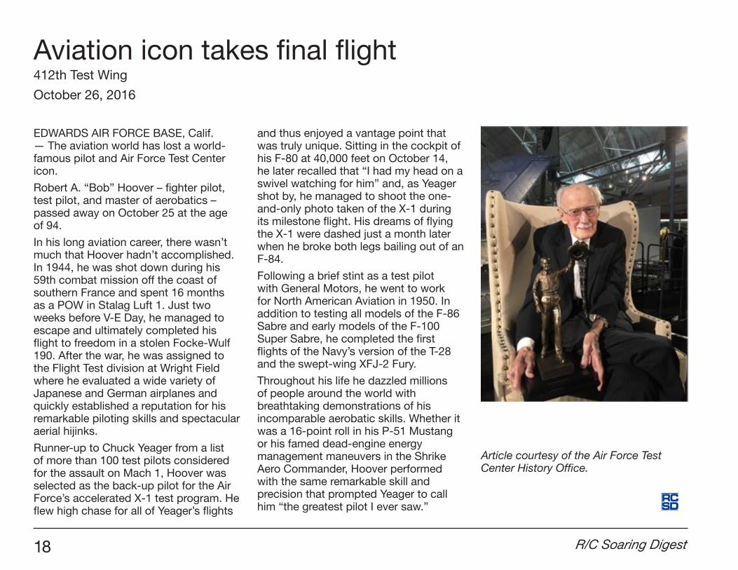
EDWARDS AIR FORCE BASE, Calif. — The aviation world has lost a world-famous pilot and Air Force Test Center icon.
Robert A. “Bob” Hoover – fighter pilot, test pilot, and master of aerobatics – passed away on October 25 at the age of 94.
In his long aviation career, there wasn’t much that Hoover hadn’t accomplished. In 1944, he was shot down during his 59th combat mission off the coast of southern France and spent 16 months as a POW in Stalag Luft 1. Just two weeks before V-E Day, he managed to escape and ultimately completed his flight to freedom in a stolen Focke-Wulf 190. After the war, he was assigned to the Flight Test division at Wright Field where he evaluated a wide variety of Japanese and German airplanes and quickly established a reputation for his remarkable piloting skills and spectacular aerial hijinks.
Runner-up to Chuck Yeager from a list of more than 100 test pilots considered for the assault on Mach 1, Hoover was selected as the back-up pilot for the Air Force’s accelerated X-1 test program. He flew high chase for all of Yeager’s flights
and thus enjoyed a vantage point that was truly unique. Sitting in the cockpit of his F-80 at 40,000 feet on October 14, he later recalled that “I had my head on a swivel watching for him” and, as Yeager shot by, he managed to shoot the one-and-only photo taken of the X-1 during its milestone flight. His dreams of flying the X-1 were dashed just a month later when he broke both legs bailing out of an F-84.
Following a brief stint as a test pilot with General Motors, he went to work for North American Aviation in 1950. In addition to testing all models of the F-86 Sabre and early models of the F-100 Super Sabre, he completed the first flights of the Navy’s version of the T-28 and the swept-wing XFJ-2 Fury.
Throughout his life he dazzled millions of people around the world with breathtaking demonstrations of his incomparable aerobatic skills. Whether it was a 16-point roll in his P-51 Mustang or his famed dead-engine energy management maneuvers in the Shrike Aero Commander, Hoover performed with the same remarkable skill and precision that prompted Yeager to call him “the greatest pilot I ever saw.”
Article courtesy of the Air Force Test Center History Office.
Aviation icon takes final flight412th Test Wing
October 26, 2016
December 2016 19
Competition rules of the class of F3B-RESRudder Elevator Spoilers
Table of contents: 1. General provisions 6 start 2. model 7 landing 3. competition site 8 review 4.competitionflights 9finalstandings 5.flightrepeats 10notes
1. General provisions:(a) “F3B-RES” is a competition class for radio-controlled glider models with a maximum
of two (2) meters wingspan and “predominant” timber construction. It is controlled viarudderandelevatorandspoilerasflaps(placedonthetopofthewingatleast5 cm / 2 in before the end bar). Note: It is not clear if “end bar” refers to a rear spar, which may not be present in all models, or the trailing edge. Thelandingflapscanbecontrolledwithoneortwoservos.Islaunchedwithabungee(RES100setofEMC-Vega,seepoint6).
(b)definitionofaradio-controlledglider:Amodelofaircraft,whichisnotequippedwithadrivedeviceanditsupwellingisbased on aerodynamic forces which act upon motionless permanent surfaces.The models must be controlled from the ground by radio remote control by the contest participants.
(c)inthecompetition,atleastfour(4)preliminaryroundsareflown.Foreachround,theparticipantsaredividedintogroups.TheresultsofeachgroupareProMille“normalized,”tocometocomparableratingsoftheflightgroups,evenifweatherconditionschangeduringaround.Thefour(4),butnotmorethaneight(8)participantswiththehighestnormalizedratingsinthepreliminaryroundsflya“Fly-off”withtwo(2)furtherfinalroundsinagroup,todeterminethefinalstandings.Thesizeofthegroupinthe“fly-off”isequivalenttothesizeoftheGroupofthepreliminary round.
(d)theparticipantsmayuseamaximumoftwo(2)modelsinthecompetition,butonlyone (1) model per round.
(e) the participants may use up to three (3) of their own helpers. These helpers may launchhismodelandretrieveit,informhimaboutflyingweather,flighttime,andchange the high start direction. At least a helper has to constantly make sure that theirownhighstartdoesnotobstructotherparticipantsatthestart.Thisrequiresthatrubber and rope are immediately withdrawn after notching at the assigned start point.
Inacrosswind,thecontestadministratorcandetermineproperorientationoflaunchesso that the ropes come to lie not one above the other.(f)theorganizershouldhaveofficialscorekeeper/timekeeperavailable.Thisisnotthecase,stopthehelpersofthepilotstheflighttime,theOrganizerdoesbutsamplemoderateoverchecksofflighttimes.Note: This is interpreted to mean that helpers for non-flying pilots are assigned by the organizer to act as official timer for flying pilots.Deviationsofmorethanthree(3)secondsforthebenefitofthepart’sleadtoazeroratingofflight.(g)thelandingpointsarerecordedwheneverpossiblealwaysbyanofficialscorekeeper.
2. model:2.1themodelconsistsgenerallyofwings,fuselageandtailunit.Flyingmodelsthatdonot have a fuselage and elevator or vertical stabilizer or none of these components are also part of the class if they have control surfaces totaling only around two (2) axes. Each ofthesecontrolsurfacesmaybecontrolledonlybyasingleservorespectively.Otherwisethe building regulations apply for the tail models accordingly.The model is “overwhelming” timber construction. This means:(a)inthewing,FRP/carbon/KevlartubesorFibreglass/carbonfibre/Kevlarcanbeused
as wing connectors and leading edges (otherwise timber).(b)thetailboomtothetailofaFibreglass/carbonfibre/Kevlartubeorprofilecanused.
Thetube/profilemaybe(asseenfromtherear)uptothehalfofthewingsurfacesdepth.
(c) the strength of a wooden fuselage may be increased by covering with Fibreglass/carbonfibre/Kevlar.
(d) all servo-control surface pushrods / pull-pull systems and suspension parts are excluded from the CFRP/GRP constraint.
2.2 usage is not allowed:(a)afullFibreglass/carbonfibre/Kevlar-orotherplasticbody(E.g.expert,EPPetc.),(b)aFibreglass/carbonfibre/Kevlarmonocoquecreatedwingorempennage,alsono
FRP/carbon/Kevlar-D-box,(c)atailorwingFibreglass/carbonfibre/Kevlar-shelledfoamorotherplastic(d)fixedorretractabledevicesforbrakingofthemodeluponlandingontheground
(E.g.pin,sawtooth-likeprotrudingdevices,etc.).Nothingmayprotrudeexceptthetowhook(s)(size:each5mmwidex15mmhigh,seenfromthefront).Thetowhook(s)canbeadjustable,butshouldbetheadjustmentdoesnothaveremotecontrol.
(e) ballast which is not located in the model or is not securely fastened.
20 R/C Soaring Digest
(f))anytransmissionofinformationfromtheflightmodeltothecompetitors,withtheexceptionofthesignalstrength,thereceivertemperatureandvoltageofthereceiverbattery (no vertical speed indicator).
(g)bytelecommunicationsystemsontheairfieldforcontestantsandhelpers(radiosandphones included).
3. competition site(a)thecompetitionmusttakeplaceonasitethatisrelativelyflatandthereisanaslowas
possible chance of slope soaring or wave gliding.(b)theflightareamusthaveadesignatedstartingline.Thestartinglineisperpendicular
tothewind,andmusthaveforeveryparticipantadesignatedstartingpoint,thatisatleasteight(8)metersareawayfromeachother.150metersapartstartinglineand“Lineoffortifications”ofhighstartrubber(seealsopoint6exception).Thehighstartmountingpointsareonthe“lineoffortifications”witheight(8)mspacing.
(c) the marked landing points should be at least eight (8) metres away from each other. Youareatleastten(10)metresdownwindfromthestartpoints.
(d) the landing points must be clearly marked on the ground. The distance between of the tip of the fuselage to the landing point is determined using a tape measure or measuring string.
(e)alandingfieldperimeterissetbytheOrganizer,acountryfieldisset.Landingsoutsidethelandingfieldaregivenazerorating.
4.competitionflights(a)theparticipantisentitledtoatleastfour(4)officialflights.(b) the participant is entitled to an unlimited number of attempts during the framework
period.(c)itisconsideredanofficialattemptifthemodelhasleftthehandoftheparticipantof
the competition or the helper and the rubber is energized.(d)inthecaseofmultipleattempts,theresultofthelastflightistheofficialresult.(e) the contest administrator is entitled to interrupt the competition and the start line in
order to reorient the launch direction if the wind direction becomes very different or even tail wind comes up. He can cancel the competition entirely if there is a wind of morethannine(9)m/s/20mph.
5.flightreps:The participant is entitled to a new execution time if:(a)hismodelcrashesduringhigh-speedlaunchorinflightwithadifferentmodelwhich
iseitherflyingortakingoff.
(b)heispreventedfromlyingabouthisstart-upbyanotherotherstart-upatthestart(firstor repetition starts).
(c)theflightwasimpededorstoppedbyaneventthatisoutsideitscontrol.Toclaimhisflightreviewinaccordancewiththeabovestatedreasons,thecompetitionparticipantsmustmakesurethattheofficialtimekeeperorthecompetitionleaderhasperceived the disability and the pilot needs to land his model as soon as possible.Shouldtheparticipantcontinuehisflightafterthedisability,itisassumedthathewaiveshis right to a new transit time.
6 start:Thehighstartis14.7meterrubberhoseand100meternylonrope(RES100setEMCVega.).Onflightsiteswhichdonotallowtoatotalcablelengthof150metres(intheextendedstate)duetosizeofthefield,theorganisermaynecessarilyshortenthenylonropeandrubberhoseproportionallytomakeareductioninflighttime.Inthecompetitionthesechanges must be pointed out.
7 landing:(a)eachparticipantisassignedhisownlandingpointbeforehiscompetitionflight.Each
contestant is responsible to assure they always use the correct point of landing.(b)duringtheprocessoflanding,thepilotandhishelpersareallowedtoresidewithin
aradiusof10metrestothepointoflanding.Morevolunteersandtheofficialtimekeepers remain at the starting line.
(c)afterthelandingthepilotsmayovertaketheirmodelswithinthetimeframe,ifnotimpededbyotherparticipantsofthegroup,aswellastheirmodels.Afterthelandingiscompleted,themodelsarenotallowedtobetouchedorbetakenawayuntiltheofficialscorekeeperoftheorganizerhasmadethedistancemeasurement(otherwisethe country rating is zero: see point 8.2 f).
(d) plug-in (lawn dart) landings are not permitted. A plug-in landing is when the tail end of the model does not rest on the ground.
8.evaluationofflightperformanceandlanding:8.1evaluationofflightperformance:The timing begins with release of the model from the high start line and ends(a) with the halt of the model(b) at the end of the frameThemaximumflighttimeissix(6)minutes(360s)withinnine(9)minutes(540s)workingtime.Thepilotachievingmorethansix(6)minutes(360s)withintheworkingtimewillhavetheovertimedeductedfromthesix(6)minutes(360s).

December 2016 21
Theflighttimeislaiddowninsecondswithoutrounding.Two(2)pointswillbeawardedpersecondflighttime.Itisinflowningroupsof4to8andtherawscoreconvertedtoProMille“normalized.”
8.2 review of landing:The distance between of the tip of the fuselage and the marked point on the ground is measuredafterthestopofthemodel.Dependingonthedistance,thefollowingpointsareawarded:
to distance points to distance points to distance pointsin meters in meters in meters0.20 100 1.80 92 9.00 600.40 99 2.00 91 10.00 550.60 98 3.00 90 11.00 500.80 97 4.00 85 12.00 451.00 96 5.00 80 13,00 401.20 95 6.00 75 14.00 351.40 94 7.00 70 15.00 301.60 93 8.00 65 15.00> 0
Forthelanding,theparticipantreceiveszeropointsif(a)heperformsaplug-inlanding(definitionseeitem7.d).(b) the model loses parts on landing or(c) the model is no longer airworthy after landing.(d) the model still has not landed at the end of the working time(e) the model touches the pilot or his helper(f) the model is touched or taken away by the pilot or his assistant after the landing andbeforetheofficialmeasurement.
ZEROpointsfortheentiretask(flightandlanding)willbeawarded,if(a)themodellandsoutsideofthelandingperimeterestablishedbytheOrganizerprior to the competition.(b)themodelstillhasnotlanded30secondsaftertheendoftheworkingtime.
9finalranking:Thefinalscoreofthecompetitionisdeterminedbytheprecedenceofthefinalroundsfortheparticipantsofthe“fly-off”andfortheremainingparticipantsbytherankingofthepreliminaryrounds.Ifthefinalroundisnotflown,therankingoftheflownpreliminaryroundsisthefinalscoreoftheentirecompetition.
10.NotesforthecompetitionEachparticipantisflyingattheirownriskandliability,hehastoproveavalidinsurancecover.Claimsagainsttheorganiser,theorganisersandtheparticipantsthemselves are excluded.Themaximumtotallengthofthehighstart-up(dependsontherespectivespace),istobe indicated in pre-competition announcements.Themaximumflighttimeisproportionaltothetotallengthofthehighstart(seepoint 6).Withthismessage,thesubscriberagreestoundergotheflightregulationsandtherules in all points.
01.05.2014R. DeckerF3B speaker
This is an English translation of the German text.Initial translation by Bing Translator<https://www.bing.com/translator>.
Corrections, revisions and notes by RCSD.
Also available as a 8.5" x 11" downloadable PDF:<http://www.rcsoaringdigest.com/Supplements/F3B-RES Regulations.pdf>
22 R/C Soaring Digest
X-Plane Communication Toolbox (XPC)Ames Research Center, Moffett Field, California
The X-Plane Connect Toolbox is an open-source research tool used to interact with the commercial flight simulator software X-Plane. XPC allows users to control aircraft and receive real-time state information from aircraft simulated in XPlane using functions written in C, C++, Java, MathWorks’ MATLAB, or Python in real time over the network. This research tool has been used to visualize flight paths, test control algorithms, generate ghost traffic, create third-party autopilot, perform hardware-in-the-loop testing, simulate an active airspace, or generate out-the-window visuals for inhouse flight simulation software. Possible applications include active control of an X-Plane simulation, flight visualization, recording states during a flight, or interacting with a mission over UDP.
XPC was originally created to support prognostic-based automated aviation decision-making technologies developed by the diagnostics and prognostics group at NASA Ames Research Center. Prior to the creation of the X-Plane Connect Toolbox, researchers had no means to perform detailed software-in-the-loop verification tests of control algorithms running in the MathWorks environments in preparation for performing full-scale flights. This tool has since been generalized and expanded to facilitate use by hobbyists, researchers, and others.
Communication between the MATLAB, C/C++, Java, or Python clients and X-Plane is established using an X-Plane plug-in. The clients communicate with X-Plane over UDP to control a vehicle or environments by setting parameters like throttle, various control surface positions, brakes, etc., or to receive live state information. The plug-in uses the standard XPlane software development kit to accomplish this. UDP communications in MATLAB are conducted using Java commands, which run natively in MATLAB, and do not require any additional MATLAB toolboxes. Code examples have also been included in the open-source distribution.
—————
This work was done by Christopher Teubert, Jason Watkins, and Bfian Bole of Ames Research Center. This software is available for use. To request a copy, please visit <https://software.nasa.gov/software/ARC-17185-1>.
NASA Tech Briefs, September 2016
A Structural Joint with Multi-Axis Load Carrying Capacity Langley Research Center, Hampton, Virginia
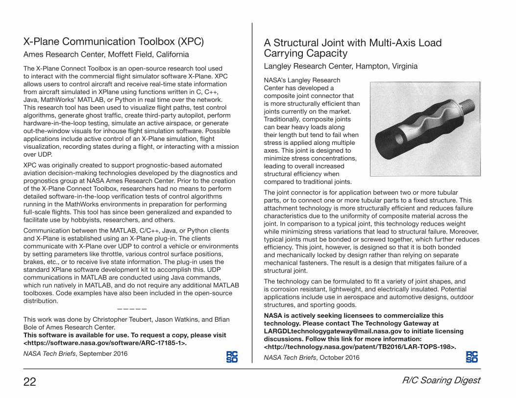
NASA’s Langley Research Center has developed a composite joint connector that is more structurally efficient than joints currently on the market. Traditionally, composite joints can bear heavy loads along their length but tend to fail when stress is applied along multiple axes. This joint is designed to minimize stress concentrations, leading to overall increased structural efficiency when compared to traditional joints.
The joint connector is for application between two or more tubular parts, or to connect one or more tubular parts to a fixed structure. This attachment technology is more structurally efficient and reduces failure characteristics due to the uniformity of composite material across the joint. In comparison to a typical joint, this technology reduces weight while minimizing stress variations that lead to structural failure. Moreover, typical joints must be bonded or screwed together, which further reduces efficiency. This joint, however, is designed so that it is both bonded and mechanically locked by design rather than relying on separate mechanical fasteners. The result is a design that mitigates failure of a structural joint.
The technology can be formulated to fit a variety of joint shapes, and is corrosion resistant, lightweight, and electrically insulated. Potential applications include use in aerospace and automotive designs, outdoor structures, and sporting goods.
NASA is actively seeking licensees to commercialize this technology. Please contact The Technology Gateway at [email protected] to initiate licensing discussions. Follow this link for more information: <http://technology.nasa.gov/patent/TB2016/LAR-TOPS-198>.
NASA Tech Briefs, October 2016
December 2016 23
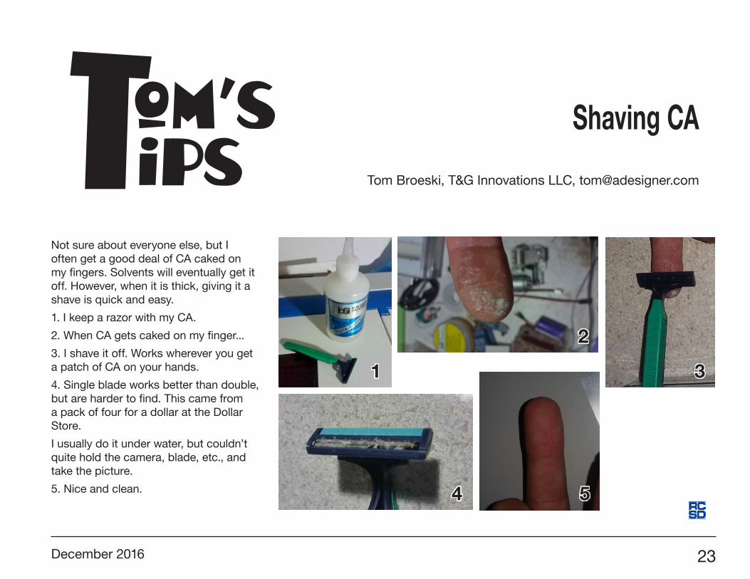
Not sure about everyone else, but I often get a good deal of CA caked on my fingers. Solvents will eventually get it off. However, when it is thick, giving it a shave is quick and easy.
1. I keep a razor with my CA.
2. When CA gets caked on my finger...
3. I shave it off. Works wherever you get a patch of CA on your hands.
4. Single blade works better than double, but are harder to find. This came from a pack of four for a dollar at the Dollar Store.
I usually do it under water, but couldn’t quite hold the camera, blade, etc., and take the picture.
5. Nice and clean.
Tom’sips
Shaving CA
Tom Broeski, T&G Innovations LLC, [email protected]
1
2
3
4 5
24 R/C Soaring Digest
It has been more than a year since I wrote the initial article describing the design and construction of the BullSiGh – a Thermal Flying Wing. I forgot in which installment of RCSD it featured – Google to the rescue!
The first construction article can be found with this nifty Google search trick “site:[domain] [search word] Google “site:rcsoaringdigest.com BullSiGh” without the “ ”. This will list all occurrences of BullSiGh.
See that article here: <http://www.rcsoaringdigest.com/pdfs/RCSD-2014/RCSD-2014-03.pdf#page=27>
In the first season I did manage to do three attempts on winch-starting the Bull, but only the first succeeded enough to actually get it in the air and judge if it could actually fly.
Some low speed stability issues arose from these attempts, due to not enough flying speed early on tow/winch. I decided I had to take the Bull to the slope – to once and for all see if it was
stable in flight. Slope-launch is so much more docile and, if the wind is hard, then you may be able to trim the model while it rests securely in your hand.
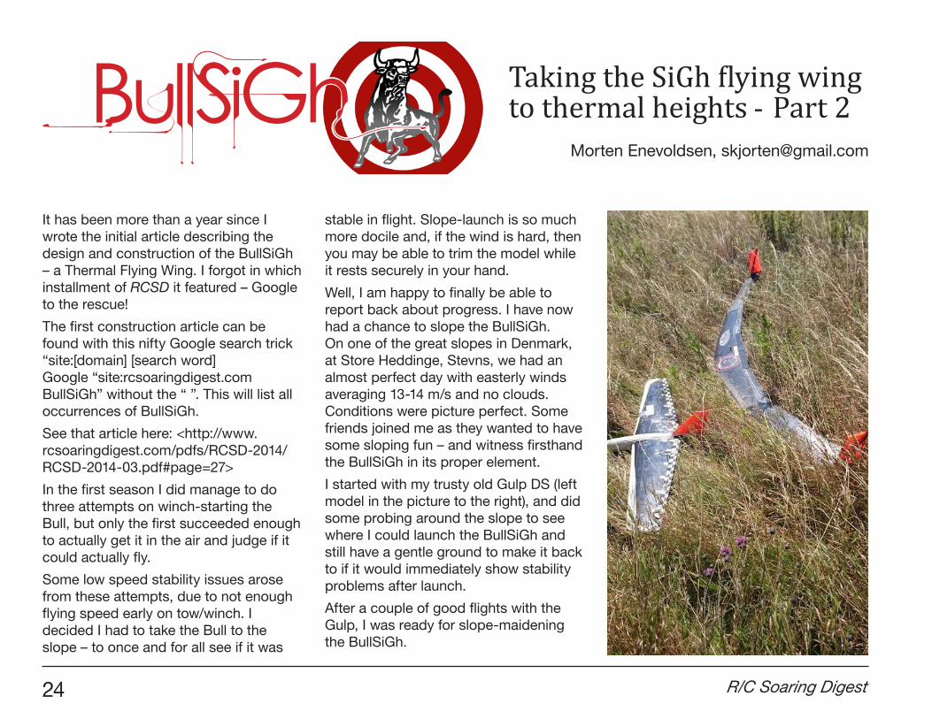
Well, I am happy to finally be able to report back about progress. I have now had a chance to slope the BullSiGh. On one of the great slopes in Denmark, at Store Heddinge, Stevns, we had an almost perfect day with easterly winds averaging 13-14 m/s and no clouds. Conditions were picture perfect. Some friends joined me as they wanted to have some sloping fun – and witness firsthand the BullSiGh in its proper element.
I started with my trusty old Gulp DS (left model in the picture to the right), and did some probing around the slope to see where I could launch the BullSiGh and still have a gentle ground to make it back to if it would immediately show stability problems after launch.
After a couple of good flights with the Gulp, I was ready for slope-maidening the BullSiGh.
Morten Enevoldsen, [email protected]
BullSiGh Taking the SiGh flying wing to thermal heights - Part 2
December 2016 25
I instructed my photographer in my new phone’s video-recording, and he was confident that he would nail it during my first launch/flight.
As history would show – he didn’t quite! I apologize as the launch video was cut short as he was trying to zoom, but haphazardly powered off the phone... He quickly got it back up again, but the first nasty and nerve-wrecking trimming rounds with the BullSiGh will be forever locked in the bystanders’ memories. Sorry.
But after initial trimming of both elevator and aileron the Bull showed me that it wanted to go fast and high in the incredible lift on the slope. Any composite flying wing is by nature slippery and fast if pointed to the ground. BullSiGh is no different - in a matter of what felt like seconds it had sped from one extreme of the large slope 500 m in one direction and passed us to go to the other extreme of the slope. It was really covering some ground as I took it low and used all the wind to gain kinetic energy and at the ends did a hammerhead turn, to come back down in the other direction at speed.
I was thrilled at how good it felt after the initial trimming for straight flight in both normal and speed phases. It definitely does not require larger winglets at slope speed. Perhaps in slow thermal flight. But I will try to assess this at a later date.
After more than a year where I had doubts about stability with the BullSiGh because of not so nice winch-launches, I proved once and for all that my design decisions where sound and that the Bull showed good and solid performance on the slope. It tracked like a steam-train.
It is a big bird at more than 3m plus the 30 cm ~ 1" winglets, weighing in at 2220 g, so I had to anticipate this when flying, which I do not at all with the Gulp.
But the Bull had much better energy retention, and tracked solidly through violent rotors on the slope (which we saw in abundant numbers on this day). I kept growing more cocky by every pass of the slope with BullSiGh, so finally I started racing from one slope to another with a very violent rotor/turbulence pattern in between. I was just flabbergasted at how well it tracked through this difficult layer of turbulence as if it was on rails. I was very impressed. The Gulp had just tested the same “waters” and had been thrown around in the turbulence like a leaf in the wind – even though my gulp is ballasted to a weight of 1100g.
I had a chance to test the flap braking and its effect on elevator. To my great satisfaction it immediately climbs when flaps are applied. This might even be enough that the application of start-flaps require some diown elevator to keep it steady on winch. This will make the tip sections also positively flapped,
improving the lift-distribution during ascent on winches. So my initial thoughts on copying this part of the original Italian SiGh glider worked perfectly also on this much larger span thermal wing.
After about 20 min. in the air, destiny finally caught up with me as a rotor flung the wing into a super-fast backward flip, and in the process cracking one of the winglets loose from its mount in midair. With only one winglet still working and from the sudden break-down in speed this maneuver took, I could not control it anymore and could just observe as it spun slowly, caught in the wind, and blew far behind us downwind on the slope into a field with some fierce looking crops.
Model-pilots know that if you lose your model in a field like this, you can kiss that model goodbye, as these branches are impenetrable with long sharp thorns without security clothes. But my friend Peter Fleischer and I soldiered along the field downwind towards the impact point hoping to salvage what was left of the BullSiGh.
After what seemed like a three minute walk through some tough grass, I found it lying next to the tough field in long grass. The only additional damage sustained during impact was the other winglet mount had broken off, too. Phew! So I already know that at least the winglet mount points need alterations and some beefing-up in the future.
26 R/C Soaring Digest
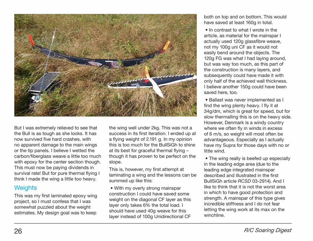
But I was extremely relieved to see that the Bull is as tough as she looks. It has now survived five hard crashes, with no apparent damage to the main wings or the tip panels. I believe I wetted the carbon/fiberglass weave a little too much with epoxy for the center section though. This must now be paying dividends in survival rate! But for pure thermal flying I think I made the wing a little too heavy.
WeightsThis was my first laminated epoxy wing project, so I must confess that I was somewhat puzzled about the weight estimates. My design goal was to keep
the wing well under 2kg. This was not a success in its first iteration. I ended up at a flying weight of 2.191 g. In my opinion this is too much for the BullSiGh to shine at its best for graceful thermal flying – though it has proven to be perfect on the slope.
This is, however, my first attempt at laminating a wing and the lessons can be summed up like this:
• With my overly strong mainspar construction I could have saved some weight on the diagonal CF layer as this layer only takes 6% the total load. I should have used 40g weave for this layer instead of 100g Unidirectional CF
both on top and on bottom. This would have saved at least 160g in total.
• In contrast to what I wrote in the article, as material for the mainspar I actually used 120g glassfibre weave, not my 100g uni CF as it would not easily bend around the objects. The 120g FG was what I had laying around, but was way too much, as this part of the construction is many layers, and subsequently could have made it with only half of the achieved wall thickness. I believe another 150g could have been saved here, too.
• Ballast was never implemented as I find the wing plenty heavy. I fly it at 34g/dm, which is great for speed, but for slow thermalling this is on the heavy side. However, Denmark is a windy country where we often fly in winds in excess of 6 m/s, so weight will most often be advantageous. Especially as I actually have my Supra for those days with no or little wind.
• The wing really is beefed up especially in the leading edge area (due to the leading edge integrated mainspar described and illustrated in the first BullSiGh article RCSD 03-2914). And I like to think that it is not the worst area in which to have good protection and strength. A mainspar of this type gives incredible stiffness and I do not fear letting the wing work at its max on the winchline.
December 2016 27
Trouble in ParadiseI quickly realized when introducing the BullSiGh to its right element that special solution to impending problems had to be found in new ways. These were:
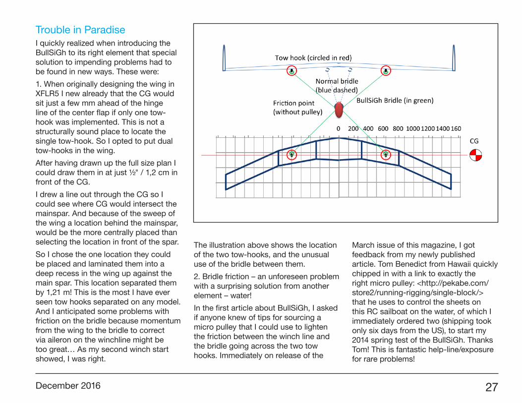
1. When originally designing the wing in XFLR5 I new already that the CG would sit just a few mm ahead of the hinge line of the center flap if only one tow-hook was implemented. This is not a structurally sound place to locate the single tow-hook. So I opted to put dual tow-hooks in the wing.
After having drawn up the full size plan I could draw them in at just ½" / 1,2 cm in front of the CG.
I drew a line out through the CG so I could see where CG would intersect the mainspar. And because of the sweep of the wing a location behind the mainspar, would be the more centrally placed than selecting the location in front of the spar.
So I chose the one location they could be placed and laminated them into a deep recess in the wing up against the main spar. This location separated them by 1,21 m! This is the most I have ever seen tow hooks separated on any model. And I anticipated some problems with friction on the bridle because momentum from the wing to the bridle to correct via aileron on the winchline might be too great… As my second winch start showed, I was right.
The illustration above shows the location of the two tow-hooks, and the unusual use of the bridle between them.
2. Bridle friction – an unforeseen problem with a surprising solution from another element – water!
In the first article about BullSiGh, I asked if anyone knew of tips for sourcing a micro pulley that I could use to lighten the friction between the winch line and the bridle going across the two tow hooks. Immediately on release of the
March issue of this magazine, I got feedback from my newly published article. Tom Benedict from Hawaii quickly chipped in with a link to exactly the right micro pulley: <http://pekabe.com/store2/running-rigging/single-block/> that he uses to control the sheets on this RC sailboat on the water, of which I immediately ordered two (shipping took only six days from the US), to start my 2014 spring test of the BullSiGh. Thanks Tom! This is fantastic help-line/exposure for rare problems!
28 R/C Soaring Digest
3. The third problem that I foresee is my possibly too small winglets. Possibly the maiden flight showed instability at low speed, which could indicate too small winglets. Another possibility is too sharp a leading edge on the winglets, which will make them extremely prone to stalls (which directly translates to tip stalls).
As the first video of the maiden flight shows – I encountered a tip stall early after having jumped off the winch too soon and gliding out and starting a slow left circle that had the wing enter an unrecoverable spin to the ground on the very first winch start. Not a nice experience.
I will for now not make any changes (also as I have no access to a foam-cutter anymore), and I will have to do my first flights with BullSiGh as it is. If they prove dangerous to tip stall again, I will try and reshape the LE to a more rounded shape that matches the actual airfoil more. The winglets were my first ever lamination work, and I learned greatly from them. But I only made that one pair.
Low visibility at great distancesThermalling often takes the model far away (over 1300m with my Supra) from where I fly it, so visibility gets more important. Here the model flight-image or visible clues to how it is pointed in space gets crucial. Inherently a flying wing only has the winglets as clues to how it is
pointed - as opposed to a where normal planform has the fuselage as well as the fin to help spot it - unless it is banking at a high angle, where it will reveal more of the planform/wing as a visual clue to what it is doing. This is why I have made very large orange patterns on the underside of the wing and winglets.
But experience with the BullSiGh has taught me that flying wings are harder to see at great distances due to the low cross section of the entire airframe as it is only a wing with winglets. So up high and out far – I must admit that BullSiGh is harder to see clearly than my Supra, although the wingspan is almost identical between the two.
Another explanation of the underside pattern/decals is that they actually work as visual altitude gauge, so I can visually guesstimate how high the model is flying. The stripes have varying widths, so will “disappear” at height. Another tip I picked up from an old article in this magazine.
Planned ImprovementsFor improving the wing, I cannot make it any lighter, although I plan on doing some serious sanding of the main wing section. To see if I can get it to thermal as it was designed for in slow thermal turns, where a good flying wing will really shine.
Better Winch-controlWith Peter Wick I decided that my present V-line from the winch-line to the two tow hooks needs not be with a miniscule block/pulley, maybe even without it, as a little friction in this point is actually beneficial, provided that I start with that bridle perfectly aligned.
And how would I know how to align it perfectly?
Well, as Peter puts it, you just tie the pulley right in the center of this bridle, so it cannot move from side to side more than a few mm. This would enable safe launches from winch. So this will be my first step in the new season. I only need to make sure I can get to steering speed in as few meters of flying from launch as possible.
WingletsWinglets will be redone with altering the knife sharp leading edges, into more airfoil-true softer edges. This I fear will make them slightly heavier. And, as Simone and Ghisleri, the designers of my inspiration the SiGh, mentioned in a mail, the tip sections really need to be light, or the main section leading edge will have to be weighted unnecessarily. I learned it the hard way, and had to put in additionally 340g of lead in the leading edge of the center section due to my excessive use of epoxy.
December 2016 29
Obviously I would have loved to leave that weight behind. But the planform dictates this extra weight.
PodIf I made some form of a pod, I know I could lighten the structure by 300g bringing it just under 2000g flying weight, which I consider a better wing loading for thermalling. As it is now at 2220g, it is enjoyable on the slope. So a pod to bring down overall weight to a minimum is an option providing for more lever-arm for the receiver and battery (and hopefully no lead at all). The servos cannot be placed further forward, as they are integrated in the wing at their positions. Maybe I will call this podded version of the plane the “BullSiGh Unleaded”!
Was the BullSiGh a bullseye?It is always the question you pose after a design project. I originally setup this prioritized list of success parameters for the BullSiGh to gauge its success:
1. Great thermalling a. In floating conditions with no or weak wind. Calls for light weight construction.b. In stronger wind, where the BullSiGh’s higher weight can actually give it an edge.
2. High launches from winch. a. High design Cl. b. High strength required.
3. Best competition performance in F3J/ F3B as possible.
a. Best glide ratio and minimum sink is required – hopefully beating the Supra’s performance in these aspects. b. Calls for high speed, so ballasting is built-in.
4. Resistance to flutter – as much of the above is achieved only through extreme speed at launch and on highspeed legs of F3B.
5. Ultimately I could live with lower launch height than a normal planform – if the wing suffers in this respect, which they usually do.
6. I need to be able to take the wing apart for transportation.
Well – the results are in!1. TBD – Great thermalling at low speed – This really is yet inconclusive. I simply have not yet had much success winch starting the beast. But my confidence in its ability to do so is now restored. I know that stability is good if speed can be kept up. In case I can make a podded “unleaded” version I am confident that its potential to thermal well will be good.
2. TBD – High winch-launches
3. TBD - a. The thermal performance is still not tested thoroughly enough to make any conclusions; b. High speed has been proven at the slope in 11-14 m/s winds where BullSiGh was positively
zipping along the slope countering very rough rotors of turbulence.
4. Flutter resistance – It seems that the high speed tests on the slope is showing the wing to be stable at very high speeds, almost reaching the speeds it will meet on hard winch launches. So I am carefully hoping that this point is silenced, and dealt with, due to my many design ideas to fight flutter in the wing-tip sections.
5. TBD – Does this wing launch lower than a traditional planform?
6. Taking the wing apart for transportation – Check. The wing is broken into three pieces for transportation (5 incl. winglets). The longest center-wing is almost 2m. But I can easily manage it in my car folding the rear-seat down.
Videos of the first slope-flyingLaunch: <https://www.youtube.com/watch?v=-47pvY3MLEM> Although short, it gives a good impression of how windy this slope-day was.
<https://www.youtube.com/watch?v=afRuLXrF-GU> <https://www.youtube.com/watch?v=WXrwDpcNpGM> Flying showing the speed and energy retention during high hammerhead turns.
30 R/C Soaring Digest
The Wright Brothers were the first to apply engineering methods to the problems of controlled flight making them the first Aeronautical Engineers. Earlier experimenters were more like inventors or hobbyists and none documented their experiments in such detail. When published 1900 aeronautical theories proved to have significant errors, they used their experimental data to correct the errors and developed new design methods.
Wilber Wright became interested in flying from reading news reports of Lilienthal’s flights and his death in a glider crash. He wrote to the Smithsonian Institution for information on flight and began by defining the problems as far as he could from the available data.
In 1901, Wilber wrote “The difficulties which obstruct the pathway to success in flying machines are of three general classes: (1) Those relate to the construction of the sustaining wings; (2)
Those which relate to the generation and application of the power required to drive the machine through the air; (3) Those related to the balancing and steering of the machine after it is actually in flight.” (Ref 1) He considered the first two essentially solved and concentrated on the third. He soon found aerodynamics not as solved as he first though and he had to design propellers and- build engines for his Flyers.
Wilber’s first idea for positive roll control was rotating wing tips (wingerons) but weight and complexity made them impractical for his kites. While twisting a empty bicycle inner tube box, he realize that the Platt Truss of Chanute’s biplane glider could be made flexible enough to twist for roll control by removing the fore and aft bracing and replacing them with control cables.
Safety was a primary concern since it was Lilienthal’s death that got Wilber interested in flight. He originally intended
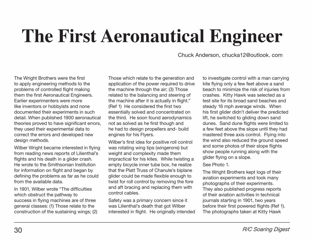
to investigate control with a man carrying kite flying only a few feet above a sand beach to minimize the risk of injuries from crashes. Kitty Hawk was selected as a test site for its broad sand beaches and steady 16 mph average winds. When his first glider didn’t deliver the predicted lift, he switched to gliding down sand dunes. Sand dune flights were limited to a few feet above the slope until they had mastered three axis control. Flying into the wind also reduced the ground speed and some photos of their slope flights show people running along with the glider flying on a slope.
See Photo 1.
The Wright Brothers kept logs of their aviation experiments and took many photographs of their experiments. They also published progress reports of their aviation activities in technical journals starting in 1901, two years before their first powered flights (Ref 1). The photographs taken at Kitty Hawk
The First Aeronautical EngineerChuck Anderson, chucka12@outlook. com
December 2016 31
were shipped to Dayton and developed in Orville’s back yard dark room. All surviving glass plate negatives are preserved in the Library of Congress.
They calculated the expected results using available theory and compared the flight test data with predictions. After the 1900 tests at Kitty Hawk, Wilber concluded that the reason for the failure to produce the predicted lift might caused by one or more reasons. He wrote “This deficiency we supposed might be by one or more of the following causes: (1) That the depth of the
curvature (camber) was insufficient, being only 1 in 22 instead of 1 in 12. (2) That the cloth used in our wings was not sufficiently air tight. (3) That the Lilienthal tables might themselves be somewhat in error. We decided to arrange our machine for the following year so that the depth of curvature of its surfaces could be varied at will and its covering be air-proofed.” (Ref 1)
The wire diagonals of the glider’s Pratt Truss made it adjustable allowing easy changes of camber and dihedral at Kitty Hawk. The struts were attached to the
wings spars with a single bolt to allow the struts to pivot as the wings warped. This made the glider easy to repair after hard landings.
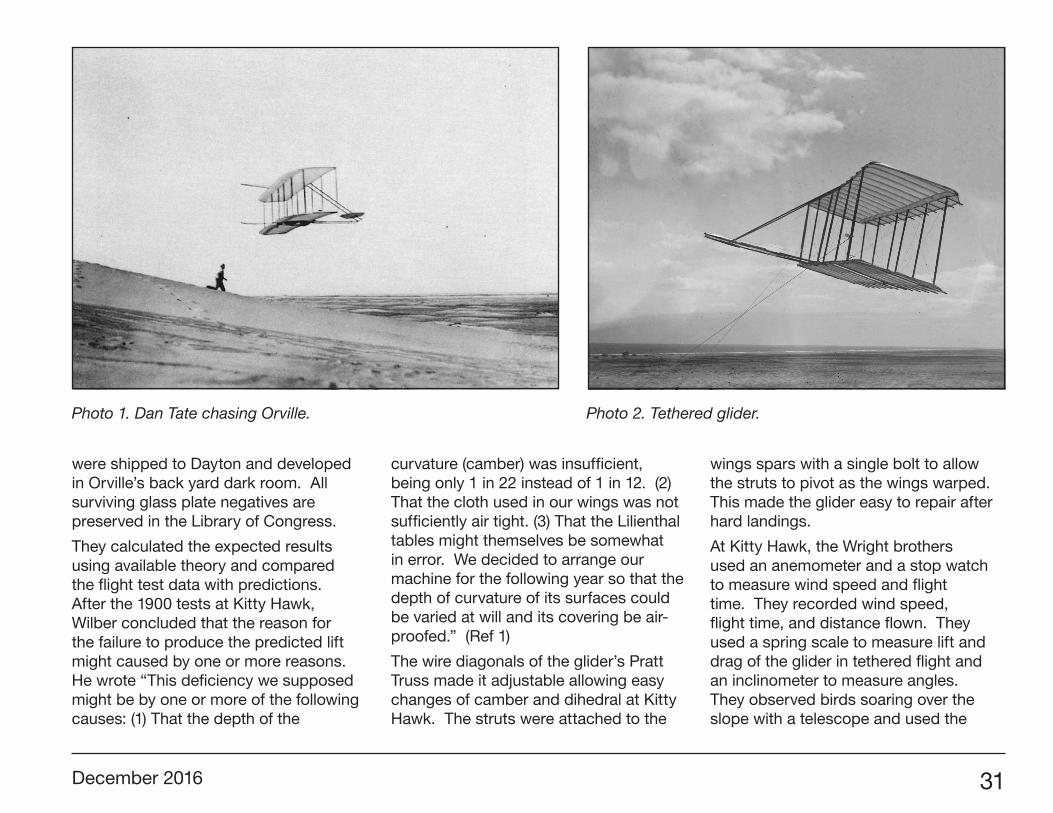
At Kitty Hawk, the Wright brothers used an anemometer and a stop watch to measure wind speed and flight time. They recorded wind speed, flight time, and distance flown. They used a spring scale to measure lift and drag of the glider in tethered flight and an inclinometer to measure angles. They observed birds soaring over the slope with a telescope and used the
Photo 1. Dan Tate chasing Orville. Photo 2. Tethered glider.
32 R/C Soaring Digest
inclinometer to estimate glide angle and angle of attack.
See Photo 2
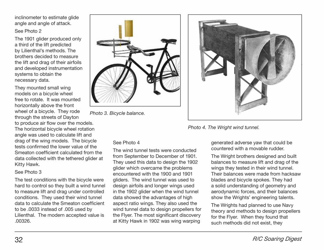
The 1901 glider produced only a third of the lift predicted by Lilienthal’s methods. The brothers decided to measure the lift and drag of their airfoils and developed instrumentation systems to obtain the necessary data.
They mounted small wing models on a bicycle wheel free to rotate. It was mounted horizontally above the front wheel of a bicycle. They rode through the streets of Dayton to produce air flow over the models. The horizontal bicycle wheel rotation angle was used to calculate lift and drag of the wing models. The bicycle tests confirmed the lower value of the Smeaton coefficient calculated from the data collected with the tethered glider at Kitty Hawk.
See Photo 3
The test conditions with the bicycle were hard to control so they built a wind tunnel to measure lift and drag under controlled conditions. They used their wind tunnel data to calculate the Smeaton coefficient to be .0033 instead of .005 used by Lilienthal. The modern accepted value is .00326.
See Photo 4
The wind tunnel tests were conducted from September to December of 1901. They used this data to design the 1902 glider which overcame the problems encountered with the 1900 and 1901 gliders. The wind tunnel was used to design airfoils and longer wings used in the 1902 glider when the wind tunnel data showed the advantages of high aspect ratio wings. They also used the wind tunnel data to design propellers for the Flyer. The most significant discovery at Kitty Hawk in 1902 was wing warping
generated adverse yaw that could be countered with a movable rudder.
The Wright brothers designed and built balances to measure lift and drag of the wings they tested in their wind tunnel. Their balances were made from hacksaw blades and bicycle spokes. They had a solid understanding of geometry and aerodynamic forces, and their balances show the Wrights’ engineering talents.
The Wrights had planned to use Navy theory and methods to design propellers for the Flyer. When they found that such methods did not exist, they
Photo 3. Bicycle balance.
Photo 4. The Wright wind tunnel.
December 2016 33
developed their own. How they went about developing a theory of propellers is typical of the way the Wright brothers went about solving problems. Wilber wrote “Our tables made the designing of wings an easy matter, and the screw propellers are simply wings traveling in a spiral course. We anticipated no troubles from this source. We had been unable to find anything of value in any of the works to which we had access so that we worked out a theory of our own”.
“After long arguments, we often found ourselves in the ludicrous position of each have been converted to the other’s side with no more agreement than when the discussion began.” This is now called brain storming.
In January 1903 they built a slightly larger wind tunnel and studied the performance of 28-inch long propellers while developing their propeller design theory
After the successful flights on December 17, 1903, they considered the basic
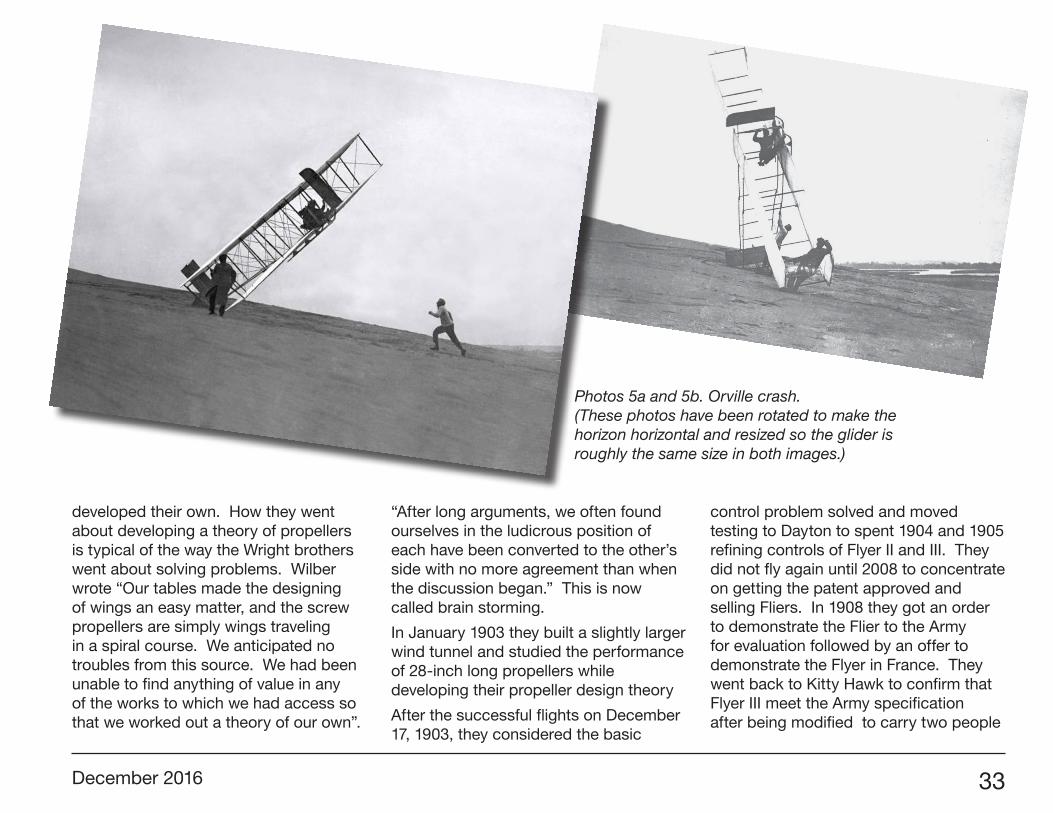
control problem solved and moved testing to Dayton to spent 1904 and 1905 refining controls of Flyer II and III. They did not fly again until 2008 to concentrate on getting the patent approved and selling Fliers. In 1908 they got an order to demonstrate the Flier to the Army for evaluation followed by an offer to demonstrate the Flyer in France. They went back to Kitty Hawk to confirm that Flyer III meet the Army specification after being modified to carry two people
Photos 5a and 5b. Orville crash. (These photos have been rotated to make the horizon horizontal and resized so the glider is roughly the same size in both images.)
34 R/C Soaring Digest
seated upright. The 1905 Flyer III used for the test was damaged and left in their shed at Kitty Hawk after they had obtained the necessary data to satisfy the Army contract.
The brothers split up in 1909 with Wilber demonstrating Flyer III in France and Orville testing it for the Army in Ft. Myers Va. They switched to a rear horizontal stabilizer for Model B Flyer when new pilots had trouble learning to fly the first production Model A Flyer.
The Wright brothers had a lot of time to observe slope and thermal flight of birds during the weeks they camped on the beach at Kitty Hawk and understood how birds exploited rising air to fly without expending energy. Until they finished developing three axis control in 1902, they restricted flying to low altitude and wind under 30 mph so flight times were usually less than 20 seconds. In 1903, they flew the 1902 glider for practice while working out problems with the Flyer propeller drive. They flew in higher winds and at higher altitudes which let them increase flight times to over a minute.
While they stopped glider flying after 1903, Wilber never quit thinking about soaring like buzzards. He referred to flying in rising air current as using a gravity engine and understood that a glider in an updraft descending at a slower rate than the air was rising could remain aloft indefinitely.
In his article Flying as a Sport—Its Possibilities published in the February 29 1908 issue of Scientific American, Wilber Wright discusses the possibility that “men will eventually learn to fly without motors in the manner of soaring birds”. In 1910, Orville was instructing in their flying school at Montgomery Alabama when he encountered a strong thermal at 1500 feet altitude and could not descend for five minutes even with the engine idling.
In a 1910 interview with the Wrights, New York World reporter Kate Carew ask “What is the best you can do for the plain business man after an exhausting day downtown.” Orville said “If he didn’t want to make a trip to any particular place he could fly up to a great height, shut off the motor and soar about on ascending currents of air as the great birds do.”
The Wright Brothers planned to return to Kitty Hawk in 1911 to continue exploring soaring and built an experimental glider based on their Model B Flyer. It had more stability and a new rudder for increased control. Business and legal matters prevented Wilber from going to Kitty Hawk so on October 7 1911, Orville and his brother Lorin went to Kittty Hawk with two assistants and accomplished an enormous about of experimenting in only three weeks.
Kill Devil Hill is a cone shaped sand dune so slope flying had to be flown into the
wind. This meant that Orville had to fly at wind speed instead of flying at higher air speed parallel to a ridge making control more difficult. Orville stated that “Flying in a 25-meter-per-second (about 55 mph) wind is no snap, and I can tell you that it keeps one pretty busy with the levers.” The glider crashed twice in high winds and several modifications were made to increase control power and stability.
See Photos 5 a and 5b.
Orville extended the distance between the tail and wings 4.5 feet to increase rudder and elevator effectiveness. When that proved insufficient, he added a vertical stabilizer just ahead of the wing and a larger elevator and rudder using parts from the damaged Flyer III they had left in Kitty Hawk in 1908. The final modification adjusted the center of gravity by hanging a 12 pound bag of sand from a beam in front of the wing. These modifications increased control and stability sufficiently that Orville was able to fly in winds up to 60 mph and at- altitude up to 50 feet above Kill Devil Hill. He set a record of 9 minutes 45 seconds that stood for over 10 years.
See Photo 6.
After he finished the Kitty Hawk soaring experiments, Orville wrote “A better knowledge of these air currents, so that one could keep his machine constantly in the rising trends, would enable one to
December 2016 35
remain aloft without power much longer than has yet been done” (Ref 4).
Wilber died in 1912 forcing Orville to give up experimenting and take over running the company. How much more could they have done if Wilber have lived?
I am amazed by the quality of the data the Wright brothers obtained with the tools available in 1900. I am an Aerospace Engineer with 3500 hours flying time in military aircraft as well as 32 years experience conducting wind tunnel tests. I would have trouble
duplicating the Wright Brothers results with the instrumentation and equipment they used.
I used Ref 4 as the main source to write this article. I especially enjoyed the technical articles originally presented to the Western Society of Engineers and published in Smithsonian reports and other technical journals between 1902 and 1908. Ref 5 presents the story of the Wright brothers at Kitty Hawk in their own words and photographs in a much more readable form. It contains many examples of the Wright’s humor. In one quote, Orville tells about a mouse waking him up to put more food in the mousetrap.
Ref 1 Wilber Wright, “Some Aeronautical Experiments.” Journal of the Western Society of Engineers, December 1901
Ref 2 The Wright Flyer, an Engineering Perspective, Wolko and Anderson, National Air and Space Museum, 1987
Ref 3 McFarland, Marvin W. (ed) The papers of Wilbur and Orville Wright. McGraw-Hill Book Co., New York, 1953.
Ref 4 The Published Writing of Wilber and Orville Wright, Smithsonian Books, 2000
Ref 5. Wind and Sand The Story of the Wright Brothers at Kitty Hawk, Westcott and Degen, New York: H.N. Abams, 1983
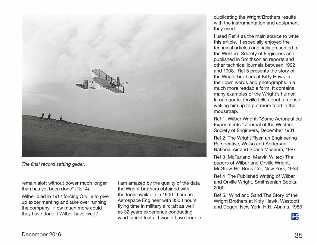
The final record setting glider.
36 R/C Soaring Digest
4
Ka 3
5
Bergfalke 11-55
2
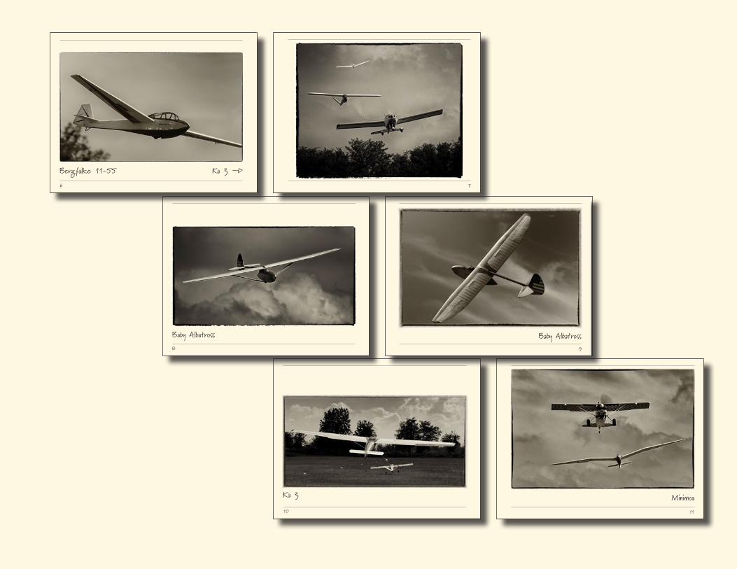
All photos in this album have been reproduced at a minimum of 300 dpi.
3
Baby Albatross
18 September 2016, Cremona Italy
Photo Album by Elia Passerini
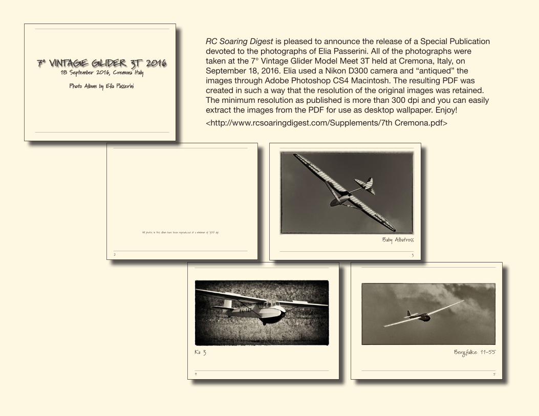
7° VINTAGE GLIDER 3T 2016
RC Soaring Digest is pleased to announce the release of a Special Publication devoted to the photographs of Elia Passerini. All of the photographs were taken at the 7° Vintage Glider Model Meet 3T held at Cremona, Italy, on September 18, 2016. Elia used a Nikon D300 camera and “antiqued” the images through Adobe Photoshop CS4 Macintosh. The resulting PDF was created in such a way that the resolution of the original images was retained. The minimum resolution as published is more than 300 dpi and you can easily extract the images from the PDF for use as desktop wallpaper. Enjoy!
<http://www.rcsoaringdigest.com/Supplements/7th Cremona.pdf>
December 2016 37
10
Ka 3
11
Minimoa
8
Baby Albatross
9
Baby Albatross
6
Ka 3 ÍBergfalke 11-55
7
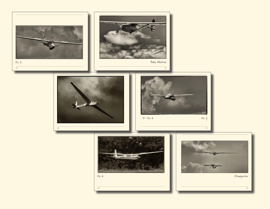
38 R/C Soaring Digest
17
Rhonsperber
16
Ka 6
14 15
ß Ka 6 Ka 3
13
Baby Albatross
12
Ka 3
December 2016 39
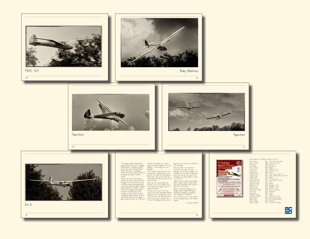
PARTICIPANTS 7° VINTAGE GLIDER 3T 2016Bertoli, Wlady (VI) Swiss Trainer (tow plane)Goletto, Fiorello (BG) Tiramisu (tow plane)Sala, Egidio (MB) SparvieroTorchio, Marco (CN) Baby AlbatrosForza, Francesco (MN) GheppioCavallari, Carlo (LO) Minimoa & KA 1Icardi, Flavio (GE) Schweizer 1-26Prandelli, Walter (BG) MaedaCondotta, Alessio (BZ) Topaze Loravia & KA 8Crugnola, Luigi (MI) Komar & Grunau Baby & Kirby KiteSalvatico, Paolo (SV ) SagittaSannino, Francesco (BG) CTV ArlecchinoMarchioretto, Paolo (VI) CVV3 Arcore & StraleDebenedetti, Carlo (SV) KA 3Migliorini, Stefano (RO) HabichtBattocchio, Lucio (RO) Bergfalke 11-55Goletto, Nicola (RO) Bergfalke 11-55Foddai, Giovanni (GE) KA 6E – KA 4Mitterstainer, Giorgio (GE) ASK 18 & MinimoaRodi, Marco (LO) RhonsperberSisani, Danilo (PG) UrendoTenneriello, Andrea (MI) MinimoaDi Gennaro, Guillermo (VI) PWS 101 & KA 6Ungari, Simone (CR) Maule M7 (tow plane)Pattoni, Marco (CR) Piper PA18 (tow plane)Pattoni, Giorgio (CR) Moswey 3Pogliacomi, Fabrizio (CR) Patchwork (tow plane)
22
Ka 6
23
The Vintage Glider Model Meet, organized every year by the “Gruppo Aeromodellistico Cremonese (GAC)” led by the active President Marco Pattoni, took place on September 18th 2016 in the airfield of Annicco (Cremona), reaching its seventh edition. Despite the meteo predicting bad weather, not even a drop of rain fell throughout the day; not only, the sun has shined steady, producing beautiful cumulus that generated good thermals. Unfortunately, the pessimistic weather forecast discouraged some vintage enthusiasts to participate at the meeting. In spite of that 25 pilots coming from different parts of North and Central Italy with 32 vintage glider models did show up to fly their
beautiful scale models. Five power planes were made available to tow the sailplanes, so that waiting time was negligible. The models on the field were scale reproductions of sailplanes from various parts of the world from Germany to Poland, from Japan to the USA, from Switzerland to Austria, and last but not least from Italy. More and more model builders pay attention to the scale details, such as the cockpit of the glider with its original instruments. The pilot must be also in the same scale of the model and possibly wearing vintage suits, hat and glasses of the time. Of course the seat belt and the control stick must be included. For the most demanding modelers the pilot
may have the owner’s face, obtained by 3D technology. And what about color scheme? It has to have the same color and markings of the full size sailplane. The faithfulness of the models is improving every year and also the scale size is increasing , with many sailplanes in scale 1:3 and 1:2,5.Flights went on without any breaking and in complete safety till 6pm when many pilots disassembled their models to make the way to home. Another successful meeting of the Vintage Glider Model Meeting 3T Cremona, rewarding the organizers and satisfying the attendees. See you next year at the 8th edition of the meeting, always on the Annicco airfield.
— Vincenzo Pedrielli
20
Sparviero
21
Sparviero
18
PWS 101
19
Baby Albatross