Embed Size (px)
Citation preview
Technician’s Handbook
This manual is updated as new information and models are released. Visit our website for the latest manual.
www.manitowocfsg.com
America’s Quality Choice in Refrigeration
Soda Systems & SuperChil™Refrigeration Units
Part Number STH12 9/10


Safety Notices
As you work on Manitowoc equipment, be sure to pay close attention to the safety notices in this handbook. Disregarding the notices may lead to serious injury and/or damage to the equipment.
Throughout this handbook, you will see the following types of safety notices:
Procedural Notices
As you work on Manitowoc equipment, be sure to read the procedural notices in this handbook. These notices supply helpful information which may assist you as you work.
Throughout this handbook, you will see the following types of procedural notices:
NOTE: Text set off as a Note provides you with simple, but useful, extra information about the procedure you are performing.
! WarningText in a Warning box alerts you to a potentialpersonal injury situation. Be sure to read theWarning statement before proceeding, and workcarefully.
! CautionText in a Caution box alerts you to a situation inwhich you could damage the equipment. Be sureto read the Caution statement before proceeding,and work carefully.
ImportantText in an Important box provides you withinformation that may help you perform aprocedure more efficiently. Disregarding thisinformation will not cause damage or injury, but itmay slow you down as you work.
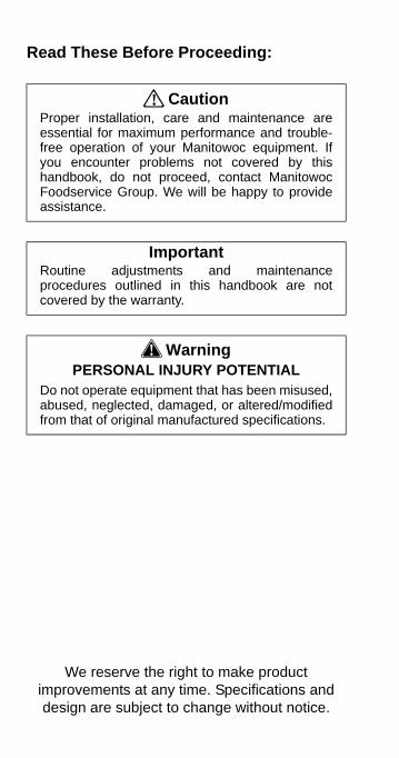
Read These Before Proceeding:
! CautionProper installation, care and maintenance areessential for maximum performance and trouble-free operation of your Manitowoc equipment. Ifyou encounter problems not covered by thishandbook, do not proceed, contact ManitowocFoodservice Group. We will be happy to provideassistance.
ImportantRoutine adjustments and maintenanceprocedures outlined in this handbook are notcovered by the warranty.
! WarningPERSONAL INJURY POTENTIAL
Do not operate equipment that has been misused,abused, neglected, damaged, or altered/modifiedfrom that of original manufactured specifications.
We reserve the right to make product improvements at any time. Specifications and design are subject to change without notice.
Part Number STH12 9/10 5
Table of Contents
General InformationModel Numbers . . . . . . . . . . . . . . . . . . . . . 9How to Read a Model Number . . . . . . . . . 10Accessories . . . . . . . . . . . . . . . . . . . . . . . 10Special Applications . . . . . . . . . . . . . . . . 11Model/Serial Number Location . . . . . . . . 11Warranty Information . . . . . . . . . . . . . . . . 11
InstallationPre-installation Checklist . . . . . . . . . . . . . 13Top Mounted Ice Maker Installations . . . 15S250-M Dimensions . . . . . . . . . . . . . . . . . 16MII-250 Dimensions . . . . . . . . . . . . . . . . . 18MII-302 Dimensions . . . . . . . . . . . . . . . . . 20MII-250 Installation Kit . . . . . . . . . . . . . . . 22MII-302 Installation Kit . . . . . . . . . . . . . . . 23Refrigeration Units . . . . . . . . . . . . . . . . . . 25Safe Installation Dos and Don’ts . . . . . . . 28Location Requirements . . . . . . . . . . . . . . 30Electrical . . . . . . . . . . . . . . . . . . . . . . . . . . 34Plumbing/Water Supply . . . . . . . . . . . . . . 38Preparing Ice Bank – Non-ERC . . . . . . . . 39Preparing Ice Bank with ERC . . . . . . . . . 41
Component IdentificationTypical System . . . . . . . . . . . . . . . . . . . . . 43Connections . . . . . . . . . . . . . . . . . . . . . . . 44
MaintenanceMaintenance Schedule . . . . . . . . . . . . . . . 49Cleaning and Sanitizing the Dispensing Valves and Product Lines . . . . . . . . . . . . 54Sanitizing . . . . . . . . . . . . . . . . . . . . . . . . . 58Shipping, Storage and Relocation . . . . . 62
OperationHow the Multiplex Works . . . . . . . . . . . . . 63Differences Between the TS & SS Units . 64Equipment Setup Procedure (Non-ERC) 71
6 Part Number STH12 9/10
Start-up (Non-ERC) . . . . . . . . . . . . . . . . . 72Sequence of Operation (Non-ERC) . . . . 74Start-up (with ERC) . . . . . . . . . . . . . . . . . 76Sequence of Operation (with ERC) . . . . 78Equipment Setup Procedure (with ERC) 82Equipment Close Procedure — All Units 84
TroubleshootingElectronic Refrigeration Control (ERC) Model Error Codes . . . . . . . . . . . . . . . . . . . . . . . 87Checklist . . . . . . . . . . . . . . . . . . . . . . . . . . 98Problem Cross-reference Guide . . . . . . . 100CO2 Gas System . . . . . . . . . . . . . . . . . . . 101Carbonated Water System . . . . . . . . . . . 104Circulating System . . . . . . . . . . . . . . . . . 111Compressed Air System . . . . . . . . . . . . . 112Dispensing Valve and Tower . . . . . . . . . 114Electrical System . . . . . . . . . . . . . . . . . . . 119Refrigeration System . . . . . . . . . . . . . . . . 120Syrup System . . . . . . . . . . . . . . . . . . . . . . 123Water Booster System . . . . . . . . . . . . . . 125Water Filter System . . . . . . . . . . . . . . . . . 127When the Brix is OFF . . . . . . . . . . . . . . . 128
Component Check ProceduresTest Procedures: MPC 64A Timer/Selection Pad . . . . . . . . . . . . . . . . . . . . . . . . . . . . . . 131Dual Transformers . . . . . . . . . . . . . . . . . 133New MPC84A Portion Control Board . . . 134MOVs Field Testing . . . . . . . . . . . . . . . . . 140Test Procedures: MPC84C Timer/Selection Board . . . . . . . . . . . . . . . . . . . . . . . . . . . . 141Back-flow Preventer Maintenance . . . . . 144Head Pressure Control Valve . . . . . . . . . 145Charging Multiplex Remote Refrigeration Unit . . . . . . . . . . . . . . . . . . . . . . . . . . . . . . 147Compressor & Remote Condenser . . . . 148Agitator Condenser . . . . . . . . . . . . . . . . . 149Carbonation System A or B . . . . . . . . . . 150Circulation System A or B . . . . . . . . . . . 151ERC Control Board, Keypad & Display . 152Programming / Auto Set . . . . . . . . . . . . . 153
Part Number STH12 9/10 7
ERC Component (Output) Connector Layout 154ERC Sensor (Input) Connector Layout . 154
Component SpecificationsRefrigeration Unit Specifications . . . . . . 155S-250M Specifications . . . . . . . . . . . . . . . 156MII-302 Specifications . . . . . . . . . . . . . . . 156
ChartsRefrigerant Charge . . . . . . . . . . . . . . . . . . 157Operating Pressures . . . . . . . . . . . . . . . . 161McDonald’s Models History . . . . . . . . . . . 163Sustained Draw Curve Charts . . . . . . . . . 164
DiagramsWiring Diagrams . . . . . . . . . . . . . . . . . . . . 167Soda Wiring Diagrams . . . . . . . . . . . . . . . 185Super-Chil Wiring Diagrams . . . . . . . . . . 200Circuit Schematics . . . . . . . . . . . . . . . . . . 212Ice/Beverage Units Diagrams . . . . . . . . . 231
8 Part Number STH12 9/10
This Page Intentionally Left Blank
Part Number STH12 9/10 9
General Information
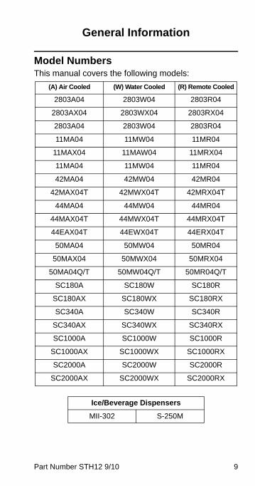
Model NumbersThis manual covers the following models:
(A) Air Cooled (W) Water Cooled (R) Remote Cooled
2803A04 2803W04 2803R04
2803AX04 2803WX04 2803RX04
2803A04 2803W04 2803R04
11MA04 11MW04 11MR04
11MAX04 11MAW04 11MRX04
11MA04 11MW04 11MR04
42MA04 42MW04 42MR04
42MAX04T 42MWX04T 42MRX04T
44MA04 44MW04 44MR04
44MAX04T 44MWX04T 44MRX04T
44EAX04T 44EWX04T 44ERX04T
50MA04 50MW04 50MR04
50MAX04 50MWX04 50MRX04
50MA04Q/T 50MW04Q/T 50MR04Q/T
SC180A SC180W SC180R
SC180AX SC180WX SC180RX
SC340A SC340W SC340R
SC340AX SC340WX SC340RX
SC1000A SC1000W SC1000R
SC1000AX SC1000WX SC1000RX
SC2000A SC2000W SC2000R
SC2000AX SC2000WX SC2000RX
Ice/Beverage Dispensers
MII-302 S-250M
10 Part Number STH12 9/10
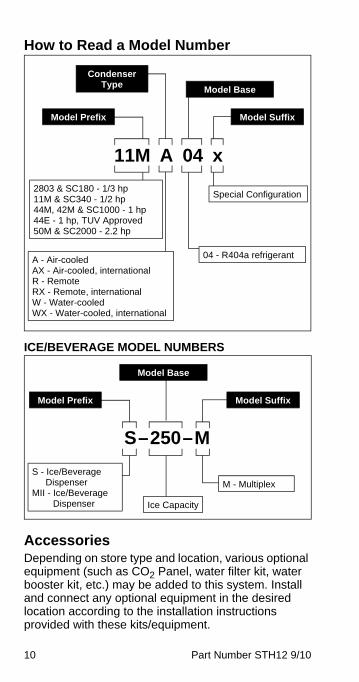
How to Read a Model Number
ICE/BEVERAGE MODEL NUMBERS
AccessoriesDepending on store type and location, various optional equipment (such as CO2 Panel, water filter kit, water booster kit, etc.) may be added to this system. Install and connect any optional equipment in the desired location according to the installation instructions provided with these kits/equipment.
Special Configuration
04 - R404a refrigerant
Model Prefix Model Suffix
Model Base
11M A 04 x
A - Air-cooledAX - Air-cooled, internationalR - RemoteRX - Remote, internationalW - Water-cooledWX - Water-cooled, international
Condenser Type
2803 & SC180 - 1/3 hp11M & SC340 - 1/2 hp44M, 42M & SC1000 - 1 hp44E - 1 hp, TUV Approved50M & SC2000 - 2.2 hp
S - Ice/Beverage Dispenser
MII - Ice/Beverage Dispenser
M - Multiplex
Ice Capacity
Model Prefix Model Suffix
Model Base
S–250–M
Part Number STH12 9/10 11
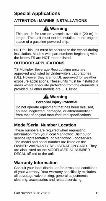
Special Applications
ATTENTION: MARINE INSTALLATIONS
NOTE: This unit must be secured to the vessel during installation. Models with part numbers beginning with the letters TS are NOT marine listed.
OUTDOOR APPLICATIONS
TS Multiplex Beverage Recirculating units are approved and listed by Underwriters Laboratories (UL). However they are not UL approved for weather exposure applications. These units must be installed in areas where adequate protection from the elements is provided, all other models are ETL listed.
Model/Serial Number LocationThese numbers are required when requesting information from your local Manitowoc Distributor, service representative, or Manitowoc Foodservice. The model and serial number are listed on the OWNER WARRANTY REGISTRATION CARD. They are also listed on the MODEL/SERIAL NUMBER DECAL affixed to the unit.
Warranty InformationConsult your local distributor for terms and conditions of your warranty. Your warranty specifically excludes all beverage valve brixing, general adjustments, cleaning, accessories and related servicing.
! WarningThis unit is for use on vessels over 66 ft (20 m) inlength. This unit must not be installed in the enginespace of a gasoline-powered ship.
! WarningPersonal Injury Potential
Do not operate equipment that has been misused, abused, neglected, damaged, or altered/modified from that of original manufactured specifications.
12 Part Number STH12 9/10
Your warranty card must be returned to activate the warranty on this equipment. If a warranty card is not returned, the warranty period can begin when the equipment leaves the factory.
No equipment may be returned without a written Return Materials Authorization (RMA). Equipment returned without an RMA will be refused at the dock and returned to the sender at the sender’s expense.
Please contact your local distributor for return procedures.
Part Number STH12 9/10 13
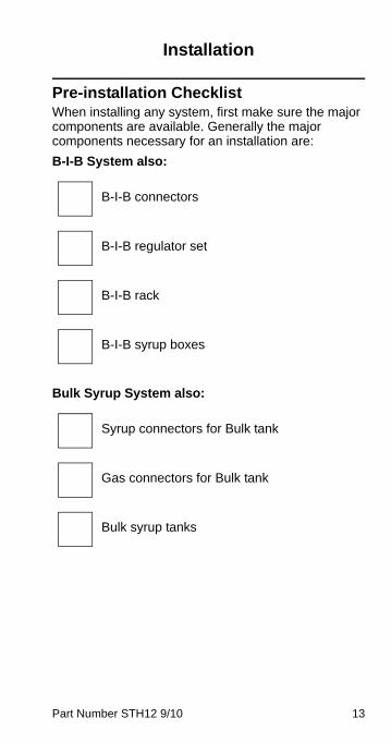
Installation
Pre-installation ChecklistWhen installing any system, first make sure the major components are available. Generally the major components necessary for an installation are:
B-I-B System also:
Bulk Syrup System also:
B-I-B connectors
B-I-B regulator set
B-I-B rack
B-I-B syrup boxes
Syrup connectors for Bulk tank
Gas connectors for Bulk tank
Bulk syrup tanks
14 Part Number STH12 9/10
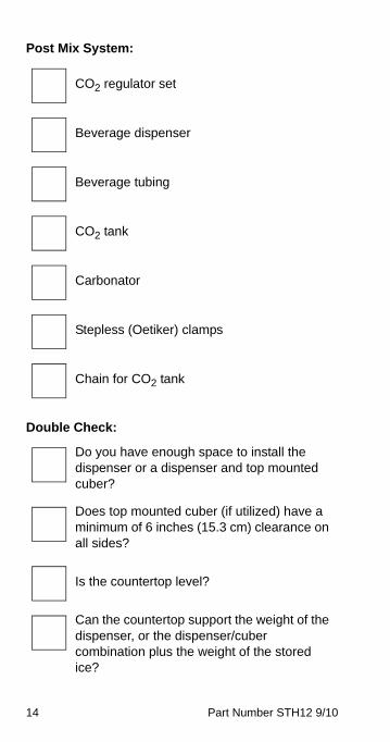
Post Mix System:
Double Check:
CO2 regulator set
Beverage dispenser
Beverage tubing
CO2 tank
Carbonator
Stepless (Oetiker) clamps
Chain for CO2 tank
Do you have enough space to install the dispenser or a dispenser and top mounted cuber?
Does top mounted cuber (if utilized) have a minimum of 6 inches (15.3 cm) clearance on all sides?
Is the countertop level?
Can the countertop support the weight of the dispenser, or the dispenser/cuber combination plus the weight of the stored ice?
Part Number STH12 9/10 15
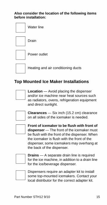
Also consider the location of the following items before installation:
Top Mounted Ice Maker Installations
Water line
Drain
Power outlet
Heating and air conditioning ducts
Location — Avoid placing the dispenser and/or ice machine near heat sources such as radiators, ovens, refrigeration equipment and direct sunlight.
Clearances — Six inch (15.2 cm) clearance on all sides of the icemaker is needed.
Front of icemaker to be flush with front of dispenser — The front of the icemaker must be flush with the front of the dispenser. When the icemaker is flush with the front of the dispenser, some icemakers may overhang at the back of the dispenser.
Drains — A separate drain line is required for the ice machine, in addition to a drain line for the ice/beverage dispenser.
Dispensers require an adapter kit to install some top-mounted icemakers. Contact your local distributor for the correct adapter kit.

16 Part Number STH12 9/10
S250-M Dimensions
I
H
B
A
EF
G
D
C
A39.81"
(101.1 cm)
B30.00"
(76.2 cm)
C9.94"
(25.2 cm)
D4.44"
(11.3 cm)
E22.63"
(57.5 cm)
F28.00"
(71.1 cm)
G31.13"
(79.1 cm)
H20.00"
(50.8 cm)
I27.44"
(69.7 cm)

Part Number STH12 9/10 17
S250-M FOOTPRINT
A B C D E
30.00"(76.2 cm)
26.00"(66.0 cm)
8.00"(20.3 cm)
7.30"(18.5 cm)
11.00"(27.9 cm)
F G H I J
15.00"(38.1 cm)
20.81"(52.8 cm)
3.00"(7.6 cm)
22.81"(57.9 cm)
31.13"(79.1 cm)
A
B
DC
EG
I
J
H
F
Minimum Area for Cutout
Maximum Area for Cutout
18 Part Number STH12 9/10
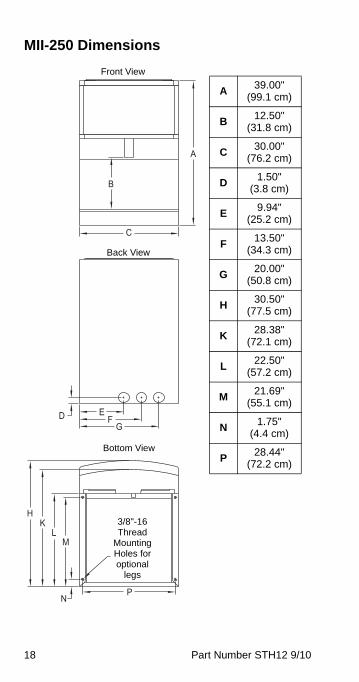
MII-250 Dimensions
N
ML
KH
P
D EF
G
C
B
A
A39.00"
(99.1 cm)
B12.50"
(31.8 cm)
C30.00"
(76.2 cm)
D1.50"
(3.8 cm)
E9.94"
(25.2 cm)
F13.50"
(34.3 cm)
G20.00"
(50.8 cm)
H30.50"
(77.5 cm)
K28.38"
(72.1 cm)
L22.50"
(57.2 cm)
M21.69"
(55.1 cm)
N1.75"
(4.4 cm)
P28.44"
(72.2 cm)
Front View
Back View
Bottom View
3/8"-16 Thread
Mounting Holes for optional
legs
Part Number STH12 9/10 19
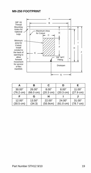
MII-250 FOOTPRINT
A B C D E
30.00"(76.2 cm)
26.00"(66.0 cm)
8.00"(20.3 cm)
8.00"(20.3 cm)
11.00"(27.9 cm)
F G H I J
12.00"(30.5 cm)
13.50"(34.3)
22.00"(55.9cm)
24.00"(61.0 cm)
31.00"(78.7 cm)
A
B
C
Maximum Area for Cutout D
F
E
3/4" NPT Fitting
Drainpan
G
H
I
J
3/8"-16 Thread
Mounting Holes for Optional
Legs
Minimum area for Cutout: Install
conduit to the back of opening to
allow forward
movement for service
of flex manifold.
20 Part Number STH12 9/10
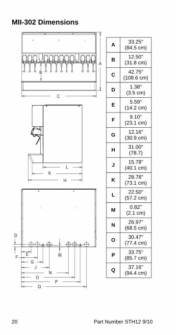
MII-302 Dimensions
A
HK
L
D
M
NO
PQ
F E
GJ
C
B
A33.25"
(84.5 cm)
B12.50"
(31.8 cm)
C42.75"
(108.6 cm)
D1.38"
(3.5 cm)
E5.59"
(14.2 cm)
F9.10"
(23.1 cm)
G12.16"
(30.9 cm)
H31.00"(78.7)
J15.78"
(40.1 cm)
K28.78"
(73.1 cm)
L22.50"
(57.2 cm)
M0.82"
(2.1 cm)
N26.97"
(68.5 cm)
O30.47"
(77.4 cm)
P33.75"
(85.7 cm)
Q37.16"
(94.4 cm)
Part Number STH12 9/10 21
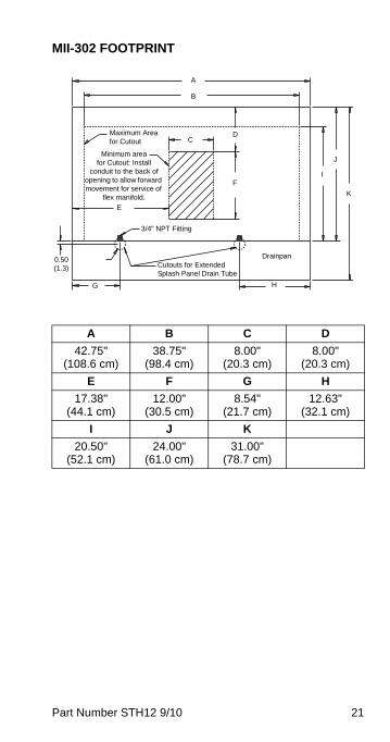
MII-302 FOOTPRINT
A B C D
42.75"(108.6 cm)
38.75"(98.4 cm)
8.00"(20.3 cm)
8.00"(20.3 cm)
E F G H
17.38"(44.1 cm)
12.00"(30.5 cm)
8.54"(21.7 cm)
12.63"(32.1 cm)
I J K
20.50"(52.1 cm)
24.00"(61.0 cm)
31.00"(78.7 cm)
A
B
CMaximum Area for Cutout
D
F
E
3/4" NPT Fitting
Drainpan
H
I
J
K
Minimum area for Cutout: Install
conduit to the back of opening to allow forward movement for service of
flex manifold.
Cutouts for Extended Splash Panel Drain Tube
G
0.50(1.3)
22 Part Number STH12 9/10
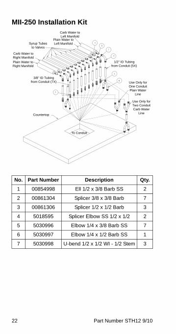
MII-250 Installation Kit
No. Part Number Description Qty.
1 00854998 Ell 1/2 x 3/8 Barb SS 2
2 00861304 Splicer 3/8 x 3/8 Barb 7
3 00861306 Splicer 1/2 x 1/2 Barb 3
4 5018595 Splicer Elbow SS 1/2 x 1/2 2
5 5030996 Elbow 1/4 x 3/8 Barb SS 7
6 5030997 Elbow 1/4 x 1/2 Barb SS 1
7 5030998 U-bend 1/2 x 1/2 WI - 1/2 Stem 3
Carb Water to Left Manifold
Plain Water to Left ManifoldSyrup Tubes
to Valves
Carb Water to Right Manifold
Plain Water to Right Manifold
3/8" ID Tubing from Conduit (7X)
1/2" ID Tubing from Conduit (5X)
Use Only for One Conduit Plain Water
Line
Use Only for Two Conduit Carb Water
LineCountertop
To Conduit

Part Number STH12 9/10 23
MII-302 Installation Kit
WATER AND SYRUP LINESThis kit facilitates connecting the unit to a 12-16 line conduit, with one or two carbonated water recirculating systems, and one or two plain water supply lines, and maximum 8 syrup product lines.
The unit is shipped with connecting lines terminating under the unit. It will be necessary to make a 90° turn
No. Part Number Description Qty.
1 00854998 Ell 1/2 x 3/8 Barb SS 2
2 00861304 Splicer 3/8 x 3/8 Barb 6
3 00861306 Splicer 1/2 x 1/2 Barb 6
4 5011751 Fitting 3/8" Y Barb 1
5 5018595 Splicer Elbow SS 1/2 x 1/2 2
6 5030996 Elbow 1/4 x 3/8 Barb SS 8
7 5030997 Elbow 1/4 x 1/2 Barb SS 4
8 5030998 U-bend 1/2 x 1/2 WI - 1/2 Stem 3
Carb Water to Left Manifold
Plain Water to Left Manifold
Syrup Tubes to
Valves
Carb Water to Right Manifold
Plain Water to Right Manifold
3/8" ID Tubing from Conduit (7X)
1/2" ID Tubing from Conduit (9X)
Use Only for One Conduit
Plain Water LineUse Only for Two Conduit
Carb Water LineCountertop
To Conduit
24 Part Number STH12 9/10
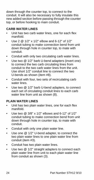
down through the counter top, to connect to the conduit. It will also be necessary to fully insulate this new added section before passing through the counter top, or before hooking to main conduit.
CARB WATER LINES• Unit has two carb water lines, one for each flex
manifold.
• Use 2 @ 1/2" x 1/2" elbow and 6-12" of 1/2" conduit tubing to make connection bend from unit down through hole in counter top, to mate with conduit.
• Conduit with only two circulating carb water lines.
• Use two @ 1/2" barb U-bend adapters (invert one) to connect the two carb circulating lines from conduit to the two carb water lines from the unit. Use short 1/2" conduit line to connect the two U-bends as shown (item #8).
• Conduit with four, two sets of recirculating carb water lines.
• Use two @ 1/2" barb U-bend adapters, to connect each set of circulating conduit lines to each carb water line from unit as shown (8).
PLAIN WATER LINES• Unit has two plain water lines, one for each flex
manifold.
• Use two @ 3/8" x 1/2" elbows and 6-12" of 1/2" conduit tubing to make connection bend from unit down through hole in counter top, to mate with conduit.
• Conduit with only one plain water line.
• Use one @ 1/2" U-bend adapter, to connect the two plain water lines to one plain water line from conduit (item #3).
• Conduit has two plain water lines.
• Use two @ 1/2" straight adapters to connect each plain water line from unit to each plain water line from conduit as shown (3).
Part Number STH12 9/10 25
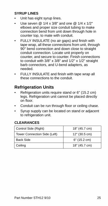
SYRUP LINES• Unit has eight syrup lines.
• Use seven @ 1/4 x 3/8" and one @ 1/4 x 1/2" elbows and proper size conduit tubing to make connection bend from unit down through hole in counter top, to mate with conduit.
• FULLY INSULATE (no air gaps) and finish with tape wrap, all these connections from unit, through 90° bend connection and down close to straight conduit connection. Locate unit properly on counter, and secure to counter. Finish connections to conduit with 3/8" x 3/8" and 1/2" x 1/2" straight barb connectors, and U-bend adapters, as needed.
• FULLY INSULATE and finish with tape wrap all these connections to the conduit.
Refrigeration Units• Refrigeration units require stand or 6" (15.2 cm)
legs. Refrigeration unit cannot be placed directly on floor.
• Conduit can be run through floor or ceiling chase.
• Syrup supply can be located on stand or adjacent to refrigeration unit.
CLEARANCES
Control Side (Right) 18" (45.7 cm)
Tower Connection Side (Left) 12" (30.5 cm)
Back Side 6" (15.2 cm)
Ceiling 18" (45.7 cm)
26 Part Number STH12 9/10
REMOTE CONDENSER LINESET REQUIREMENTS
1. Both the discharge and liquid remote condensing lines must be kept to a minimum distance for maximum performance. All Multiplex systems are capacity rated to 100 ft (30.5 m) tubing distance between the compressor and condenser. If you have another brand condenser, please add additional charge for the condenser (example: up to three (3) pounds for a MAC condenser).
2. Any vertical rise 25 ft (7.62 m) or greater must have a manufactured or installed trap (bend), in the discharge refrigeration line from the compressor to the remote condenser. A trap is necessary for every additional 25 ft (7.62 m) vertical rise. When excessive vertical rise exists, this trap allows oil to reach the condenser and return to the compressor.
ImportantIf you have a MAC Multi-Pass condenser pleaseadd three (3) pounds additional charge.
ImportantIf you exceed the 100ft line set length add.72oz/ft of line set run (one way) for every footover 100ft, to the UNIT charge
Part Number STH12 9/10 27
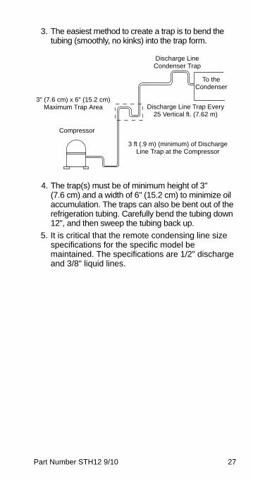
3. The easiest method to create a trap is to bend the tubing (smoothly, no kinks) into the trap form.
4. The trap(s) must be of minimum height of 3" (7.6 cm) and a width of 6" (15.2 cm) to minimize oil accumulation. The traps can also be bent out of the refrigeration tubing. Carefully bend the tubing down 12", and then sweep the tubing back up.
5. It is critical that the remote condensing line size specifications for the specific model be maintained. The specifications are 1/2" discharge and 3/8" liquid lines.
To the Condenser
Discharge Line Trap Every 25 Vertical ft. (7.62 m)
3 ft (.9 m) (minimum) of Discharge Line Trap at the Compressor
Compressor
3" (7.6 cm) x 6" (15.2 cm) Maximum Trap Area
Discharge Line Condenser Trap
28 Part Number STH12 9/10
Safe Installation Dos and Don’ts
! WarningRead the following warnings before beginning aninstallation. Failure to do so may result inpossible death or serious injury.
• Adhere to all National and Local Plumbing and Electrical Safety Codes.
• Turn OFF incoming electrical service switches when servicing, installing, or repairing equipment.
• DO NOT throw or drop a CO2 cylinder. Secure the cylinder(s) in an upright position with a chain.
• DO NOT store CO2 cylinders in temperature above 125°F (51.7°C) near furnaces, radiator or sources of heat.
! WarningDO NOT connect the CO2 cylinder(s) directly tothe product container. Doing so will result in anexplosion causing possible death or injury. It is bestto connect the CO2 cylinder(s) to a regulator(s).
! WarningCarbon Dioxide (CO2) displaces oxygen. Exposureto a high concentration of CO2 gas causes tremors,which are followed rapidly by loss of consciousnessand suffocation. If a CO2 gas leak is suspected,particularly in a small area, immediately ventilate thearea before repairing the leak. CO2 lines and pumpsmust not be installed in an enclosed space. Anenclosed space can be a cooler or small room orcloset. This may include convenience stores withglass door self serve coolers. If you suspect CO2may build up in an area, venting of the BIB pumpsand/or CO2 monitors must be utilized.
Part Number STH12 9/10 29
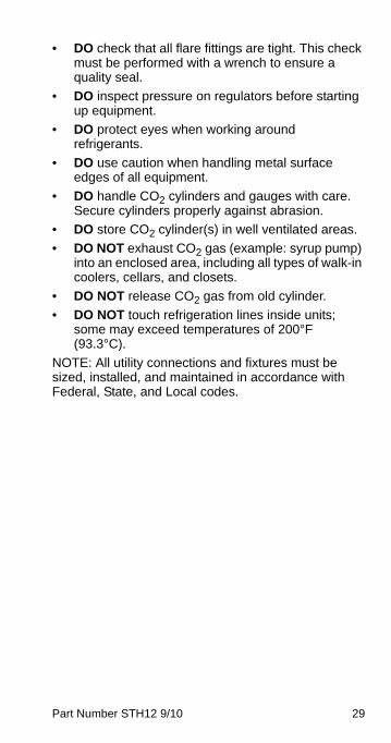
• DO check that all flare fittings are tight. This check must be performed with a wrench to ensure a quality seal.
• DO inspect pressure on regulators before starting up equipment.
• DO protect eyes when working around refrigerants.
• DO use caution when handling metal surface edges of all equipment.
• DO handle CO2 cylinders and gauges with care. Secure cylinders properly against abrasion.
• DO store CO2 cylinder(s) in well ventilated areas.
• DO NOT exhaust CO2 gas (example: syrup pump) into an enclosed area, including all types of walk-in coolers, cellars, and closets.
• DO NOT release CO2 gas from old cylinder.
• DO NOT touch refrigeration lines inside units; some may exceed temperatures of 200°F (93.3°C).
NOTE: All utility connections and fixtures must be sized, installed, and maintained in accordance with Federal, State, and Local codes.
30 Part Number STH12 9/10
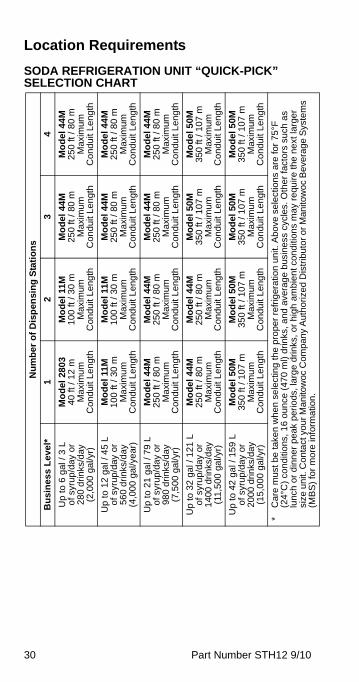
Location Requirements
SODA REFRIGERATION UNIT “QUICK-PICK” SELECTION CHART
Nu
mb
er
of
Dis
pen
sin
g S
tati
on
s
Bu
sin
es
s L
eve
l*
1
2 3
4
Up
to 6
gal
/ 3
L
of s
yrup
/da
y o
r 2
80
drin
ks/d
ay
(2,0
00
gal/y
r)
Mo
del
280
34
0 ft
/ 1
2 m
M
axi
mu
m
Con
du
it L
en
gth
Mo
del
11
M
10
0 ft
/ 3
0 m
M
axim
um
Co
ndu
it L
eng
th
Mo
del
44
M25
0 ft
/ 8
0 m
M
axi
mu
m
Con
du
it L
en
gth
Mo
del
44
M2
50
ft /
80
mM
axim
umC
on
duit
Len
gth
Up
to
12
gal
/ 4
5 L
o
f syr
up/d
ay
or
56
0 d
rinks
/da
y (4
,00
0 g
al/y
ear
)
Mo
de
l 11
M
100
ft /
30
m
Ma
xim
um
C
ond
uit
Le
ngt
h
Mo
del
11
M
10
0 ft
/ 3
0 m
M
axim
um
Co
ndu
it L
eng
th
Mo
del
44
M
250
ft /
80
m
Ma
xim
um
C
ond
uit
Le
ngt
h
Mo
del
44
M2
50
ft /
80
mM
axim
umC
on
duit
Len
gth
Up
to
21
gal
/ 7
9 L
of s
yrup
/da
y o
r 9
80
drin
ks/d
ay
(7,5
00
gal/y
r)
Mo
del
44M
25
0 ft
/ 8
0 m
M
axi
mu
m
Con
du
it L
en
gth
Mo
del
44
M
25
0 ft
/ 8
0 m
M
axim
um
Co
ndu
it L
eng
th
Mo
del
44
M
250
ft /
80
m
Ma
xim
um
C
ond
uit
Le
ngt
h
Mo
del
44
M2
50
ft /
80
mM
axim
umC
on
duit
Len
gth
Up
to 3
2 g
al /
12
1 L
of s
yrup
/da
y o
r 1
400
dri
nks
/da
y (1
1,5
00
gal/y
r)
Mo
del
44M
25
0 ft
/ 8
0 m
M
axi
mu
m
Con
du
it L
en
gth
Mo
del
44
M
25
0 ft
/ 8
0 m
M
axim
um
Co
ndu
it L
eng
th
Mo
del
50
M
35
0 ft
/ 1
07
m
Ma
xim
um
C
ond
uit
Le
ngt
h
Mo
del
50
M35
0 ft
/ 1
07
mM
axim
umC
on
duit
Len
gth
Up
to 4
2 g
al /
15
9 L
of s
yrup
/da
y o
r2
000
dri
nks
/da
y (1
5,0
00
ga
l/yr)
Mo
del
50M
3
50
ft /
10
7 m
M
axi
mu
m
Con
du
it L
en
gth
Mo
del
50
M
350
ft /
107
m
Max
imum
C
on
duit
Len
gth
Mo
del
50
M
35
0 ft
/ 1
07
m
Ma
xim
um
C
ond
uit
Le
ngt
h
Mo
del
50
M35
0 ft
/ 1
07
mM
axim
umC
on
duit
Len
gth
*C
are
mu
st b
e ta
ken
wh
en
se
lect
ing
the
pro
per
refr
iger
atio
n u
nit.
Ab
ove
se
lect
ion
s ar
e fo
r 75
°F
(24°
C)
con
diti
ons
, 16
ou
nce
(4
70 m
l) d
rin
ks, a
nd a
vera
ge
bus
ine
ss c
ycle
s. O
the
r fa
ctor
s su
ch a
s lu
nch
or
din
ne
r p
eak
per
iods
, la
rge
drin
ks, o
r h
igh
amb
ien
t con
diti
on
s m
ay
req
uire
the
next
larg
er
size
un
it. C
on
tact
yo
ur M
an
itow
oc C
ompa
ny
Au
tho
rize
d D
istr
ibu
tor
or
Man
itow
oc
Be
vera
ge
Sys
tem
s (M
BS
) fo
r m
ore
info
rma
tion
.
Part Number STH12 9/10 31
Select a location for the refrigeration unit that meets the requirements of the building plans, local codes, and personnel. The unit must be positioned for free airflow as well as for future service. The following minimum requirements must be met:
• 100 GPH (379 LTR/hr) potable water supply Models 2803/11/38; 200 GPH (757 LTR/hr) potable water supply Models 44/50
• Beverage quality CO2 gas (bulk or bottled supply) with a minimum 3/8" (.96 cm) line
• One Bag-In-Box (BIB) container of each post mix syrup flavor.
NOTE: Refer to nameplate on side of refrigeration unit for voltage and amperage specifications. Make all electrical connections at the junction box located at the top rear of unit. Optional equipment may require additional power supplies.
NOTE: Potable water connections to the equipment must comply with local plumbing code requirements, particularly the back-flow prevention requirements.
PLUMBING REQUIREMENTS – GENERALIncoming water supply must be provided before installation of the refrigeration unit and must comply with local plumbing requirements.
1. A minimum 1" (2.54 cm) water supply line with a manual shut-off valve must be plumbed at least 6 ft (183 cm) from the unit. The incoming water supply pressure must not exceed 70 psi static (4.8 bar) and be no less than 40 psi (2.8 bar) dynamic. If supply water pressure is greater than 70 psi (5 bar), a water regulator will be required.
2. Locate the drain hose, bracket, and two screws provided in the installation kit. Attach the drain hose to the water bath overflow tube located on the bottom of the refrigeration unit.
32 Part Number STH12 9/10
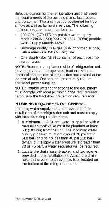
3. Connect the water manifold supply line, located on the bulkhead panel in the motor compartment to the main water supply. The main water supply shut-off valve must remain in the OFF position. If a water filter is to be installed, connect the line to the outlet fitting of the filter. Plumb according to applicable plumbing codes.
Drain Hose Connection
4. When a water cooled condenser is installed, a copper supply line (not supplied with unit) must be plumbed to the 3/8" (.965 cm) male flare fitting installed in the water shut-off assembly. The shut-off must be placed in the OFF position. A copper drain line (not supplied) is to be connected to the outlet fitting of the water cooled condenser and routed to the floor drain.
Screw
Drain Hose
Bottom of Unit
Bracket
Part Number STH12 9/10 33
WATER SUPPLY1. Use the built in fill valve that is already plumbed
into the unit.
2. An appropriate floor drain is required within 6 ft (2 m) of the unit.
3. Potable water connections to the equipment must comply with the basic plumbing code of the Building Officials and Code Administrators International, Inc. (BOCA) and the Food Service Sanitation Manual of the Food and Drug Administration. Verify local plumbing code requirements.
34 Part Number STH12 9/10
Electrical
GENERAL
MINIMUM CIRCUIT AMPACITYThe minimum circuit ampacity is used to help select the wire size of the electrical supply. (Minimum circuit ampacity is not the unit’s running amp load.) The wire size (or gauge) is also dependent upon location, materials used, length of run, etc., so it must be determined by a qualified electrician.
ELECTRICAL REQUIREMENTSRefer to unit’s Model/Serial Plate for voltage/amperage specifications.
! WarningAll wiring must conform to local, state andnational codes.

Part Number STH12 9/10 35
SPECIFICATIONS
* O
nly
the
mo
de
l 50M
with
SS
pa
rt n
um
be
rs h
ave
120
V c
om
po
nen
ts,
the
TS
do
es
no
t.
Mo
del
Vo
lt/C
ycle
/Ph
ase
Min
imu
m
Cir
cuit
Am
ps
Bre
aker
Co
mp
res
sor
2803
&
SC
180
120/
60/1
230/
50/1
20.3
9.0
25A
16A
1/3
hp.4
6 kW
11M
&
SC
340
120/
60/1
230/
50/1
21.5
10.7
30A
16A
1/2
hp.9
7 kW
44M
, 42
M &
S
C10
00
208-
230
/60/
123
0/50
/120
.620
.630
A25
A1
hp1.
9 kW
50M
120*
/208
-23
0/60
/323
0/4
00/5
0/3
25.2
11.6
30A
20A
2.2
hp2.
0 kW
SC
2000
208-
230
/60/
323
0/4
00/5
0/3
25.2
11.6
20A
15A
2.2
hp2.
0 kW

36 Part Number STH12 9/10
GROUNDING INSTRUCTIONS
This appliance must be grounded. In the event of malfunction or breakdown, grounding provides a path of least resistance for electric current to reduce the risk of electric shock.
NOTE: The refrigeration units are not equipped with a cord.
! WarningThe unit must be grounded in accordance withnational and local electrical codes.
! WarningImproper connection of the equipment-groundingconductor can result in a risk of electric shock.The conductor with insulation having an outersurface that is green with or without yellow stripesis the equipment grounding conductor. If repair orreplacement of the cord or plug is necessary, donot connect the equipment-grounding conductorto a live terminal. Check with a qualifiedelectrician or serviceman if the groundinginstructions are not completely understood, or ifin doubt as to whether the appliance is properlygrounded. Do not modify the plug provided withthe appliance — if it will not fit the outlet, have aproper outlet installed by a qualified electrician.

Part Number STH12 9/10 37
! WarningWhen using electric appliances, basicprecautions must always be followed, includingthe following:
a. Read all the instructions before using the appliance.
b. To reduce the risk of injury, close supervision is necessary when an appliance is used near children.
c. Do not contact moving parts.
d. Only use attachments recommended or sold by the manufacturer.
e. Do not use outdoors.
f. For a cord-connected appliance, the following shall be included:
• Do not unplug by pulling on cord. To unplug, grasp the plug, not the cord.
• Unplug from outlet when not in use and before servicing or cleaning.
• Do not operate any appliance with a damaged cord or plug, or after the appliance malfunctions or is dropped or damaged in any manner. Contact the nearest authorized service facility for examination, repair, or electrical or mechanical adjustment.
g. For a permanently connected appliance — Turn the power switch to the off position when the appliance is not in use and before servicing or cleaning.
h. For an appliance with a replaceable lamp — Always unplug before replacing the lamp. Replace the bulb with the same type.
i. For a grounded appliance — Connect to a properly grounded outlet only. See Grounding Instructions.

38 Part Number STH12 9/10
Plumbing/Water Supply
PLUMBING POTABLE WATER
A 1" (2.54 cm) ID copper inlet water line equipped with a 3/4" (1.905 cm) FPT adapter with shut-off must be supplied by plumber at rear of equipment. Appropriate floor drains must be provided within 6 ft (183 cm) of each unit installed.
NOTE: The carbonator in this unit is provided with a dual check valve type back-flow preventer, which conforms to ASSE 1032. The Model 50M & 44M vented backflow preventer conforms to ASSE 1022.
Potable water connections to the equipment must comply with the basic plumbing code of the Building Officials and Code Administrators International, Inc. (BOCA) and the Food Service Sanitation Manual of the Food and Drug Administration. Verify local plumbing code requirements.
ModelRequired
Water Pressure
Drain Connections
Water Supply
2803 & SC180
40 – 70 psig(2.8 – 4.9 bar)
3/4" IDwithin 6 ft (2 m)
3/8" IDEVA Line
11M & SC340
40 – 70 psig(2.8 – 4.9 bar)
3/4" ID within 6 ft (2 m)
3/8" IDEVA Line
44M, 42M &
SC1000
40 – 70 psig(2.8 – 4.9 bar)
3/4" ID within 6 ft (2 m)
1/2" IDEVA Line
50M 40 – 70 psig(2.8 – 4.9 bar)
3/4" ID within 6 ft (2 m)
1/2" IDEVA Line
SC2000 40 – 70 psig(2.8 – 4.9 bar)
3/4" ID within 6 ft (2 m)
1/2" IDEVA Line

Part Number STH12 9/10 39
Preparing Ice Bank – Non-ERC
BUILDING AN ICE BANK1. At this time, fill the unit water bath tank to the top,
or within 1/2" (1.3 cm) of the top minimum, of the overflow tube. Use a garden hose or another water supply to do this.
NOTE: A manual fill valve is incorporated into the water circuit to the carbonator tank. This valve can be used to manually add water lost for any reason. Do not leave this valve ON constantly, only use it for filling and topping off. The water bath must be drained, flushed, and refilled every six months.
2. Turn ON the switch labeled “Refrigeration”. Allow unit to run for about 15 minutes before proceeding to step 3.
3. Turn ON the switch labeled “Agitator”.
NOTE: Turn this switch OFF to perform any operations in the water bath area.
With water bath water temperature of 65°F (18°C), ice will begin to form on the evaporator coils in approximately 2 hours. The unit will build a full ice bank in approximately 4 to 6 hours (depending on ambient water temperature).
4. Before turning on the carbonator or circulator switch, verify that the pump box assembly has been mounted and connected to the unit and the appropriate syrup and water has been supplied.
Drain Tube
Overflow Tube
Water Bath Tank
Tab Clamp
40 Part Number STH12 9/10
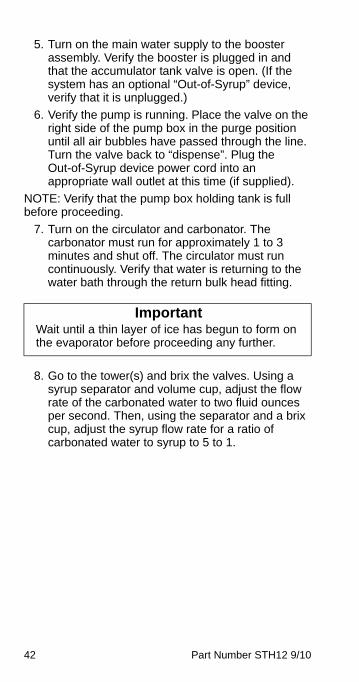
5. Turn on the main water supply to the booster assembly. Verify the booster is plugged in and that the accumulator tank valve is open. (If the system has an optional “Out-of-Syrup” device, verify that it is unplugged.)
6. Verify the pump is running. Place the valve on the right side of the pump box in the purge position until all air bubbles have passed through the line. Turn the valve back to “dispense”. Plug the Out-of-Syrup device power cord into an appropriate wall outlet at this time (if supplied).
NOTE: Verify that the pump box holding tank is full before proceeding.
7. Turn on the circulator and carbonator switches. The carbonator must run for approximately 1 to 3 minutes and shut off. The circulator must run continuously. Verify that water is returning to the water bath through the return bulk head fitting.
8. Go to the tower(s) and brix the valves. Using a syrup separator and volume cup, adjust the flow rate of the carbonated water to two fluid ounces per second. Then, using the separator and a brix cup, adjust the syrup flow rate for a ratio of carbonated water to syrup.
ImportantWait until a thin layer of ice has begun to form onthe evaporator before proceeding any further.
Part Number STH12 9/10 41
Preparing Ice Bank with ERC
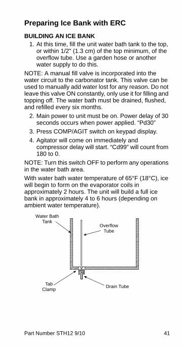
BUILDING AN ICE BANK1. At this time, fill the unit water bath tank to the top,
or within 1/2" (1.3 cm) of the top minimum, of the overflow tube. Use a garden hose or another water supply to do this.
NOTE: A manual fill valve is incorporated into the water circuit to the carbonator tank. This valve can be used to manually add water lost for any reason. Do not leave this valve ON constantly, only use it for filling and topping off. The water bath must be drained, flushed, and refilled every six months.
2. Main power to unit must be on. Power delay of 30 seconds occurs when power applied. “Pd30”
3. Press COMP/AGIT switch on keypad display.
4. Agitator will come on immediately and compressor delay will start. “Cd99” will count from 180 to 0.
NOTE: Turn this switch OFF to perform any operations in the water bath area.
With water bath water temperature of 65°F (18°C), ice will begin to form on the evaporator coils in approximately 2 hours. The unit will build a full ice bank in approximately 4 to 6 hours (depending on ambient water temperature).
Drain Tube
Overflow Tube
Water Bath Tank
Tab Clamp
42 Part Number STH12 9/10
5. Turn on the main water supply to the booster assembly. Verify the booster is plugged in and that the accumulator tank valve is open. (If the system has an optional “Out-of-Syrup” device, verify that it is unplugged.)
6. Verify the pump is running. Place the valve on the right side of the pump box in the purge position until all air bubbles have passed through the line. Turn the valve back to “dispense”. Plug the Out-of-Syrup device power cord into an appropriate wall outlet at this time (if supplied).
NOTE: Verify that the pump box holding tank is full before proceeding.
7. Turn on the circulator and carbonator. The carbonator must run for approximately 1 to 3 minutes and shut off. The circulator must run continuously. Verify that water is returning to the water bath through the return bulk head fitting.
8. Go to the tower(s) and brix the valves. Using a syrup separator and volume cup, adjust the flow rate of the carbonated water to two fluid ounces per second. Then, using the separator and a brix cup, adjust the syrup flow rate for a ratio of carbonated water to syrup to 5 to 1.
ImportantWait until a thin layer of ice has begun to form onthe evaporator before proceeding any further.
Part Number STH12 9/10 43
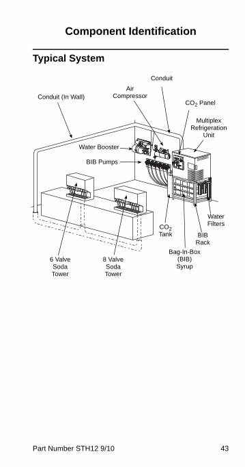
Component Identification
Typical System
Conduit (In Wall)
6 Valve Soda Tower
8 Valve Soda Tower
Water Booster
Air Compressor
Conduit
CO2 Panel
Multiplex Refrigeration
Unit
CO2 Tank
Bag-In-Box (BIB) Syrup
BIB Rack
Water Filters
BIB Pumps
44 Part Number STH12 9/10
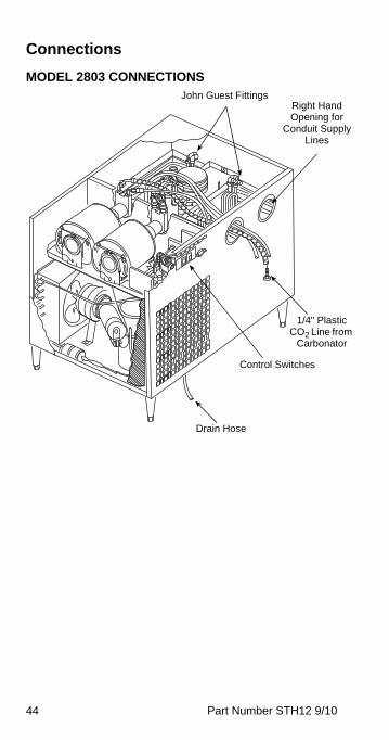
Connections
MODEL 2803 CONNECTIONSJohn Guest Fittings
Drain Hose
Control Switches
1/4" Plastic CO2 Line from
Carbonator
Right Hand Opening for
Conduit Supply Lines
Part Number STH12 9/10 45
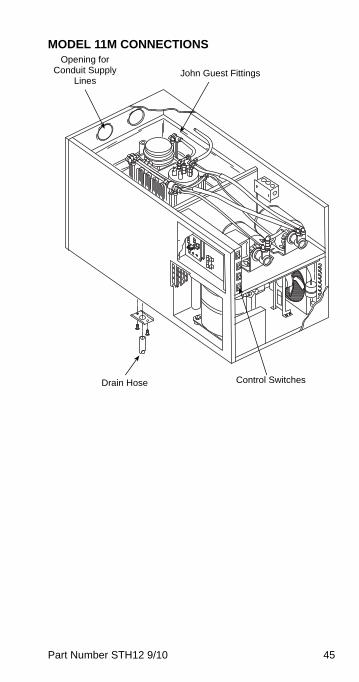
MODEL 11M CONNECTIONS
John Guest Fittings
Drain Hose Control Switches
Opening for Conduit Supply
Lines
46 Part Number STH12 9/10
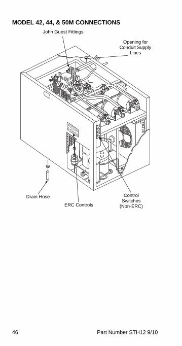
MODEL 42, 44, & 50M CONNECTIONS
John Guest Fittings
Drain Hose Control Switches
(Non-ERC)
Opening for Conduit Supply
Lines
ERC Controls
Part Number STH12 9/10 47
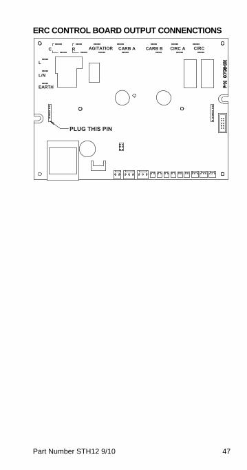
ERC CONTROL BOARD OUTPUT CONNENCTIONS
L
L/N
C R AGITATIOR CIRCB
CARB A CARB B CIRC A
EARTH
PLUG THIS PIN
48 Part Number STH12 9/10
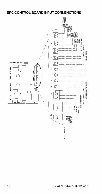
ERC CONTROL BOARD INPUT CONNENCTIONS
12
11
10
9 8
7 6
5 4
3 2
1
CO
2TS
TD
TW
TB
TA
W
L
ICE
C
A A
C
A B
H
PCO
WA
TER
HIG
H P
RO
BE
HPC
O S
WIT
CH
LO
W P
RO
BE
CO
MH
IGH
PR
OB
E GN
D+5
V D
CLO
W P
RO
BE
OU
TPU
T
CO
MH
IGH
PR
OB
E G
ND
+5V
DC
LOW
PR
OB
E O
UTP
UT
SUC
TIO
N T
EMP
LEVE
L PR
OB
E G
ND
DIS
CH
AR
GE
TEM
PC
IRC
B T
EMP
CIR
C A
TEM
P W
ATE
R B
ATH
TEM
P
Part Number STH12 9/10 49
Maintenance
Maintenance ScheduleThis section provides a list of periodic maintenance tasks and the scheduled frequency required to ensure the proper operation of your Multiplex dispensing equipment. To ensure quality beverages, prevent downtime, and reduce costs, these tasks must be performed as indicated.
PERIODIC MAINTENANCE FOR SOFT DRINK EQUIPMENT (LISTED BY MAJOR COMPONENTS)
Dispensing stations
Daily (365 times per year)
• Take temperature of finished drinks. Pour off the first and take the temperature of the second drink. The proper temperature of drinks must be 38°F (4°C) or less.
• Remove nozzles and diffusers from each dispensing valve. Clean with soap and warm water (not hot). Rinse with carbonated water and reinstall.
• Flush all dispenser drains. Pour hot water down drains at closing.
Beverage conduits
Every 4 months (3 times per year)
• Inspect beverage conduits for damage. Re-insulate and seal any uninsulated areas.
• Inspect floor chases and seal any open chase ends.
Air compressor
Monthly (12 times per year)
• Drain condensate water from air compressor tank.
Every 4 months (3 times per year)
• Inspect air compressor filter and replace if clogged. Air filter must be replaced every 6 months.
50 Part Number STH12 9/10
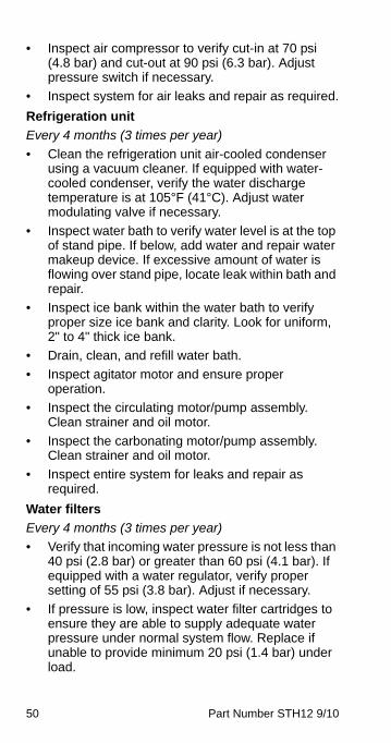
• Inspect air compressor to verify cut-in at 70 psi (4.8 bar) and cut-out at 90 psi (6.3 bar). Adjust pressure switch if necessary.
• Inspect system for air leaks and repair as required.
Refrigeration unit
Every 4 months (3 times per year)
• Clean the refrigeration unit air-cooled condenser using a vacuum cleaner. If equipped with water-cooled condenser, verify the water discharge temperature is at 105°F (41°C). Adjust water modulating valve if necessary.
• Inspect water bath to verify water level is at the top of stand pipe. If below, add water and repair water makeup device. If excessive amount of water is flowing over stand pipe, locate leak within bath and repair.
• Inspect ice bank within the water bath to verify proper size ice bank and clarity. Look for uniform, 2" to 4" thick ice bank.
• Drain, clean, and refill water bath.
• Inspect agitator motor and ensure proper operation.
• Inspect the circulating motor/pump assembly. Clean strainer and oil motor.
• Inspect the carbonating motor/pump assembly. Clean strainer and oil motor.
• Inspect entire system for leaks and repair as required.
Water filters
Every 4 months (3 times per year)
• Verify that incoming water pressure is not less than 40 psi (2.8 bar) or greater than 60 psi (4.1 bar). If equipped with a water regulator, verify proper setting of 55 psi (3.8 bar). Adjust if necessary.
• If pressure is low, inspect water filter cartridges to ensure they are able to supply adequate water pressure under normal system flow. Replace if unable to provide minimum 20 psi (1.4 bar) under load.
Part Number STH12 9/10 51
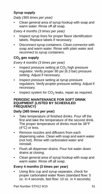
Syrup supply
Daily (365 times per year)
• Clean general area of syrup hookup with soap and warm water. Rinse off all soap.
Every 4 months (3 times per year)
• Inspect syrup lines for proper flavor identification labels. Replace labels if necessary.
• Disconnect syrup containers. Clean connector with soap and warm water. Rinse with plain water and reconnect to syrup containers.
CO2 gas supply
Every 4 months (3 times per year)
• Inspect pressure setting at CO2 high pressure regulator. Verify proper 90 psi (6.3 bar) pressure setting. Adjust if necessary.
• Inspect pressure setting at syrup pressure regulators. Verify propter pressure setting. Adjust if necessary.
• Inspect system for CO2 leaks, repair as required.
PERIODIC MAINTENANCE FOR SOFT DRINK EQUIPMENT (LISTED BY SCHEDULED FREQUENCY)
Daily (365 times per year)
• Take temperature of finished drinks. Pour off the first and take the temperature of the second drink. The proper temperature of drinks must be 38°F (4°C) or less.
• Remove nozzles and diffusers from each dispensing valve. Clean with soap and warm water (not hot). Rinse with carbonated water and reinstall.
• Flush all dispenser drains. Pour hot water down drains at closing.
• Clean general area of syrup hookup with soap and warm water. Rinse off all soap.
Every 4 months (3 times per year)
• Using Brix cup and syrup separator, check for proper carbonated water flows (standard flow: 5 oz. in 4 seconds, fast flow: 10 oz. in 4 seconds)

52 Part Number STH12 9/10
and syrup to water ratios at each dispensing station. Adjust as required.
• Inspect beverage conduits for damage. Re-insulate and seal any uninsulated areas.
• Inspect floor chases and seal any open chase ends.
• Inspect air compressor filter and replace if clogged. Air filter must be replaced every 6 months.
• Inspect air compressor to verify cut-in at 70 psi (4.8 bar) and cut-out at 90 psi (6.3 bar). Adjust pressure switch if necessary.
• Inspect system for air leaks and repair as required.
• Clean the refrigeration unit air-cooled condenser using a vacuum cleaner. If equipped with water-cooled condenser, verify the water discharge temperature is at 105°F (41°C). Adjust water modulating valve if necessary.
• Inspect water bath to verify water level is at the top of stand pipe. If below, add water and repair water makeup device. If excessive amount of water is flowing over stand pipe, locate leak within bath and repair.
• Inspect ice bank within the water bath to verify proper size ice bank and clarity. Look for uniform, 2" to 4" thick ice bank.
• Drain, clean, and refill water bath.
• Inspect agitator motor and ensure proper operation.
• Inspect the circulating motor/pump assembly. Clean strainer and oil motor.
• Inspect the carbonating motor/pump assembly. Clean strainer and oil motor.
• Inspect entire system for leaks and repair as required.
• Verify that incoming water pressure is not less than 40 psi (2.8 bar) or greater than 60 psi (4.1 bar). If equipped with a water regulator, verify proper setting of 55 psi (3.8 bar). Adjust if necessary.
Part Number STH12 9/10 53
• If pressure is low, inspect water filter cartridges to ensure they are able to supply adequate water pressure under normal system flow. Replace if unable to provide minimum 40 psi (1.4 bar) under load.
• Inspect syrup lines for proper flavor identification labels. Replace labels if necessary.
• Disconnect syrup containers. Clean connector with soap and warm water. Rinse with plain water and reconnect to syrup containers.
• Inspect pressure setting at CO2 high pressure regulator. Verify proper 90 psi (6.3 bar) pressure setting. Adjust if necessary.
• Inspect pressure setting at syrup pressure regulators. Verify propter pressure setting. Adjust if necessary.
• Inspect system for CO2 leaks. Repair as required.
54 Part Number STH12 9/10
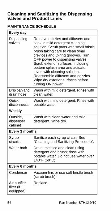
Cleaning and Sanitizing the Dispensing Valves and Product Lines
MAINTENANCE SCHEDULE
Every day
Dispensing valves
Remove nozzles and diffusers and soak in mild detergent cleaning solution. Scrub parts with small bristle brush taking care to clean small crevices and O-ring grooves. Turn OFF power to dispensing valves. Scrub exterior surfaces, including bottom splash area and actuator lever, with cleaning solution. Reassemble diffusers and nozzles. Wipe dry exterior surfaces before turning ON power.
Drip pan and drain hose
Wash with mild detergent. Rinse with clean water.
Quick disconnects
Wash with mild detergent. Rinse with potable water.
Weekly
Outside, dispenser cabinet
Wash with clean water and mild detergent. Wipe dry.
Every 3 months
Syrup circuits
Sanitize each syrup circuit. See “Cleaning and Sanitizing Procedure”.
Water bath Drain, melt ice and clean using detergent and brush; rinse with potable water. Do not use water over 140°F (60°C).
Every 6 months
Condenser Vacuum fins or use soft bristle brush (scrub brush).
Air purifier filter (if equipped)
Replace.
Part Number STH12 9/10 55
CLEANING EQUIPMENT AND SUPPLIES• Recommended cleaner: Any caustic-base (low
sudsing, non-perfumed, easily rinsed) detergent solution which provides a minimum 2% sodium hydroxide. The solution must be prepared in accordance with the manufacturer’s instructions. Solution temperature must be between 90°F (32°C) and 110°F (43°C). Temperatures in excess of this can cause internal damage to the dispensing valve components.
• Recommended sanitizer: Any sanitizer which provides a minimum of 120 parts per million (120 milligrams per liter) of available chlorine. Solution temperature must be between 90°F (32°C) and 110°F (43°C). Temperatures in excess of this can cause internal damage to the dispensing valve components.
• Two five gallon (figals) syrup tanks and fittings, cleaned and sanitized (one for cleaner; one for sanitizer)
• Containers for cleaner and sanitizer solutions
• Clean, non-abrasive cloths
• Buckets
• Small Brush
• Extra Nozzles
• Extra Jumpers
56 Part Number STH12 9/10
CLEANING AND SANITIZING PROCEDURENOTE: Cleaning and sanitizing is not required for potable water circuits. Potable water lines must remain connected and operational during the cleaning and sanitizing procedures for syrup circuits.
Cleaning and dispensing valves
1. Disconnect each syrup container from its product line. Remove product from the lines by purging with clean warm tap water until syrup has been fully purged from the product lines and valves.
2. Clean all lines and fittings with cleaning solution and rinse with clean, room temperature water to remove all traces of residual product.
Cleaning the product lines
1. To clean each valve product line, attach the valve product lines to the pressure tank containing the cleaning solution. Make sure each line is completely filled. Pressurize the lines by pulsing the valves.
Pressurizing the product lines
A. For 15 seconds turn dispensing valve ON, OFF, and then immediately ON again for 15 cycles.
B. Allow the valve to remain flowing for 3 minutes.
C. Repeat pulsing and flowing the valves again until all cleaning solution has been used.
! CautionIt is required that the Carbonated Water Linesremain connected and operational duringcleaning and sanitizing of the syrup circuits.Sanitizing of the valve without the CarbonatedWater side operation may leave bacteria in thenozzle, diffuser, and syrup tube.
Part Number STH12 9/10 57
2. Flush the cleaning solution from the lines with clean water after a minimum of 3 minutes, by pulsing the valves as described above.
3. Remove the nozzles and the diffuser assemblies from the valves. Clean with cleaning solution. Agitate the assemblies to ensure assemblies are clean. Place them in a container of sanitizing solution for 15 minutes. Wearing sanitary gloves, remove the nozzles and diffuser assemblies from the sanitizing solution. Drain each until dry and reassemble to the valves.
4. Attach each valve product line to the pressure tank containing the sanitizing solution. Be sure all connections are cleaned and sanitized before connecting to each product line.
5. Pressurize and fill the lines with sanitizing solution. Make sure lines are completely filled, Allow the sanitizing solution to flow through each valve while activating the valves for 15 cycles.
A. Leave valves OFF and allow to stand pressurized for 30 minutes.
B. Activate the valves for two (2) cycles. Flush remaining sanitizer continuously through the valves.
6. Reconnect the syrup containers to their respective circuits. Prepare the unit for operation.
7. Draw drinks to refill lines and flush the sanitizing solution from the dispenser. Taste the beverage to verify that there is no off-taste (chlorine).
! CautionDo not allow cleaning and sanitizing solutions toremain in syrup systems longer thanrecommended contact time. Exceeding contacttime will result in damage to valve components.
58 Part Number STH12 9/10
Sanitizing
BEVERAGE SYSTEM CLEANING
Sanitize the beverage system at initial start-up as well as regularly scheduled cleaning. The drain pan must be in place under soda valves, to carry away detergent and sanitizing agents that will be flushed through valves.
BAG-IN-BOX SYSTEM SANITATIONThe procedure below is for the sanitation of one syrup circuit at a time. Repeat to sanitize additional circuits.
You will need the following items to clean and sanitize the Bag-in-Box (BIB) beverage system:
• Three (3) clean buckets
• Plastic brush or soft cloth
• Mild detergent
• Unscented bleach (5% Na CL O) or Commercial sanitizer
• Bag-In-Box bag connector
1. Prepare the following in the buckets:
• Bucket 1 — warm to hot tap water for rinsing.
• Bucket 2 — mild detergent and warm to hot water.
! WarningFlush sanitizing solution from syrup system.Residual sanitizing solution left in system couldcreate a health hazard.
! WarningWhen using cleaning fluids or chemicals, rubbergloves and eye protection must be worn.
Part Number STH12 9/10 59
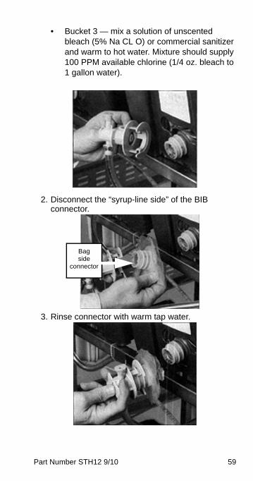
• Bucket 3 — mix a solution of unscented bleach (5% Na CL O) or commercial sanitizer and warm to hot water. Mixture should supply 100 PPM available chlorine (1/4 oz. bleach to 1 gallon water).
2. Disconnect the “syrup-line side” of the BIB connector.
3. Rinse connector with warm tap water.
Bagside
connector
60 Part Number STH12 9/10
4. Connect syrup connector to BIB connector and immerse both into Bucket 1. A “bag-side” connector can be created by cutting the connector from an empty disposable syrup bag.
5. Draw rinse water through system until clean water is dispensed. Most beverage valves allow the syrup side to be manually activated by depressing the syrup pallet.
6. Connect Bucket 2 to system.
7. Draw detergent solution through system until solution is dispensed.
8. Repeat steps 2-7 until all syrup circuits contain detergent solution.
9. Allow detergent solution to remain in the system for 5 minutes.
10. Connect Bucket 3 to system.
11. Draw sanitizing solution through system until solution is dispensed.
12. Repeat step 11 until all syrup circuits contain sanitizer solution.
13. Allow sanitizer solution to remain in system for 15 minutes.
14. Remove nozzles and diffusers from beverage valves.
15. Scrub nozzles, diffusers and all removable valve parts (except electrical parts) with a plastic brush or a soft cloth and the detergent solution.
16. Soak nozzles, diffusers and removable valve parts (except electrical parts) in sanitizer for 15 minutes.
17. Replace nozzles, diffusers and valve parts.
18. Connect Bucket 1 to system.
19. Draw rinse water through system until no presence of sanitizer is detected.
20. Attach syrup connectors to BIBs.
21. Draw syrup through system until only syrup is dispensed.
22. Discard first 2 drinks.
Part Number STH12 9/10 61
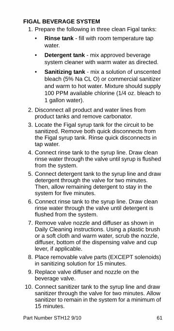
FIGAL BEVERAGE SYSTEM1. Prepare the following in three clean Figal tanks:
• Rinse tank - fill with room temperature tap water.
• Detergent tank - mix approved beverage system cleaner with warm water as directed.
• Sanitizing tank - mix a solution of unscented bleach (5% Na CL O) or commercial sanitizer and warm to hot water. Mixture should supply 100 PPM available chlorine (1/4 oz. bleach to 1 gallon water).
2. Disconnect all product and water lines from product tanks and remove carbonator.
3. Locate the Figal syrup tank for the circuit to be sanitized. Remove both quick disconnects from the Figal syrup tank. Rinse quick disconnects in tap water.
4. Connect rinse tank to the syrup line. Draw clean rinse water through the valve until syrup is flushed from the system.
5. Connect detergent tank to the syrup line and draw detergent through the valve for two minutes. Then, allow remaining detergent to stay in the system for five minutes.
6. Connect rinse tank to the syrup line. Draw clean rinse water through the valve until detergent is flushed from the system.
7. Remove valve nozzle and diffuser as shown in Daily Cleaning instructions. Using a plastic brush or a soft cloth and warm water, scrub the nozzle, diffuser, bottom of the dispensing valve and cup lever, if applicable.
8. Place removable valve parts (EXCEPT solenoids) in sanitizing solution for 15 minutes.
9. Replace valve diffuser and nozzle on the beverage valve.
10. Connect sanitizer tank to the syrup line and draw sanitizer through the valve for two minutes. Allow sanitizer to remain in the system for a minimum of 15 minutes.
62 Part Number STH12 9/10
11. Reconnect syrup and carbonated water lines.
12. Draw syrup through the lines to rinse the system. Discard drinks until at least two cups of satisfactory tasting beverage are dispensed through the valve.
Shipping, Storage and Relocation
! CautionBefore shipping, storing, or relocating this unit,syrup systems must be sanitized. After sanitizing,all liquids (sanitizing solution and water) must bepurged from the unit. A freezing environmentcauses residual sanitizing solution or waterremaining inside the unit to freeze, resulting indamage to internal components.
Part Number STH12 9/10 63
Operation
How the Multiplex WorksModel 2803 — a 1/3 HP refrigeration unit that will provide pre-mix carbonated beverages and chilled carbonated water for up to 6 gal (3 L) of syrup/day or 280 drinks/day (2,000 gal/yr) with a 40 ft (12 m) maximum conduit length. This is a remote refrigeration unit that derives its peak draw capacity from the reserve ice bank produced from a capillary tube refrigeration system. This system is controlled to cycle ON and OFF by the operation of the ice bank control. The sensing bulb that controls the ice bank is located on an adjustable bracket in the water bath.
Model 11M — a 1/2 HP refrigeration unit that will provide premix carbonated beverages and chilled carbonated water for up to 12 gal (45 L) of syrup/day or 560 drinks/day (4,000 gal/year) with a 100 ft (30 m) maximum conduit length. This is a remote refrigeration unit that derives its peak draw capacity from the reserve ice bank produced from a capillary tube refrigeration system. This system is controlled to cycle ON and OFF by the operation of the ice bank control. The sensing bulb that controls the ice bank is located on an adjustable bracket in the water bath.
Model 42M — a 1 HP refrigeration unit that will provide pre-mix carbonated beverages and chilled carbonated water for up to 50 gal (190 L) of syrup/day or 3,060 drinks/day (18,200 gal/yr) with a 250 ft (80 m) maximum conduit length. This refrigeration unit is a remote refrigeration unit that derives its peak capacity from the reserve ice bank produced from a TXV system. This system is controlled to cycle ON and OFF by the operation of the ice control. The sensing probe that controls the ice bank, is located on an adjustable bracket in the water bath.
Model 44M — a 1 HP refrigeration unit that will provide pre-mix carbonated beverages and chilled carbonated water for up to 50 gal (190 L) of syrup/day or 3,060 drinks/day (18,200 gal/yr) with a 250 ft (80 m) maximum conduit length. This refrigeration unit is a remote refrigeration unit that derives its peak capacity from the reserve ice bank produced from a TXV system. This system is controlled to cycle ON and OFF by the operation of the ice control. The sensing probe that controls the ice bank, is located on an adjustable bracket in the water bath.

64 Part Number STH12 9/10
Model 50M — a 2.2 HP Pre-mix refrigeration unit that will provide pre-mix carbonated beverages and chilled carbonated water for up to 42 gal (159 L) of syrup/day or 2,000 drinks/day (15,000 gal/yr) with a 350 ft (107 m) maximum conduit length. This refrigeration unit is a remote refrigeration unit that derives its peak capacity from the reserve ice bank produced by the operation of the compressor. This system is controlled to cycle ON and OFF by the operation of the ice bank control. The sensing bulb that controls the ice bank is located on an adjustable bracket in the water bath.
Differences Between the TS & SS UnitsMultiplex soda and water chillers may have three different series numbers. Starting in 2007 some no longer begin with an “SS”; they now begin with a “TS”. Starting in 2008, units with ERC (Electronic Refrigeration Controls) end with an “E”. The following shows you how to tell the difference between the TS version and the SS.
• The TS uses common components from Manitowoc Ice makers to assist in product and parts availability.
Part Number STH12 9/10 65
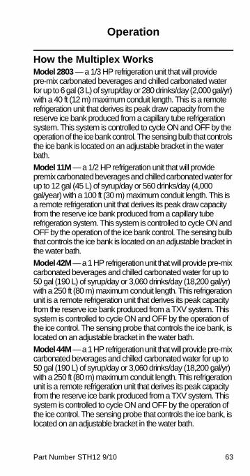
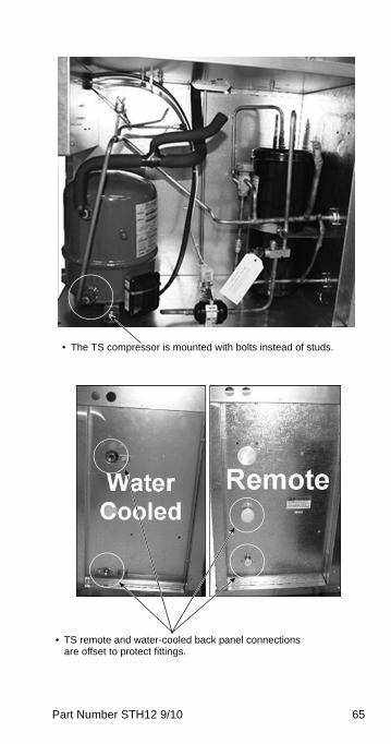
• The TS compressor is mounted with bolts instead of studs.
• TS remote and water-cooled back panel connections are offset to protect fittings.
66 Part Number STH12 9/10
WATER MANIFOLD TS
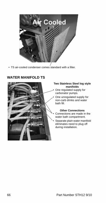
• TS air-cooled condenser comes standard with a filter.
Two Stainless Steel log style manifolds
• One regulated supply for carbonator pumps.
• One unregulated supply for non-carb drinks and water bath fill.
Other Connections• Connections are made in the
water bath compartment.
• Separate plain water manifold eliminates need to plug off during installation.

Part Number STH12 9/10 67
ELECTRICAL TS• Electrical compartment has been moved up on the unit to eliminate
water intrusion potential from the pump compartment.• All components are now 208/230V. This eliminates the need for a
neutral wire.
• New unit has service connections in the electrical compartment. Allows more room to work and more reliable connection.
• Pump protection switch has been moved to the pump compartment to eliminate potential leak point in electrical compartment.
68 Part Number STH12 9/10
WATER BATH ACCESS SS
WATER BATH ACCESS TS
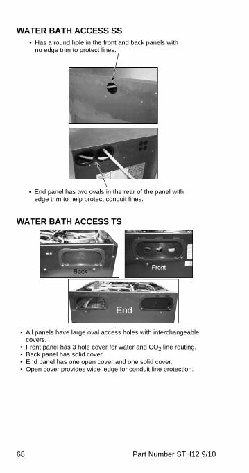
• Has a round hole in the front and back panels with no edge trim to protect lines.
• End panel has two ovals in the rear of the panel with edge trim to help protect conduit lines.
• All panels have large oval access holes with interchangeable covers.
• Front panel has 3 hole cover for water and CO2 line routing.• Back panel has solid cover.• End panel has one open cover and one solid cover.• Open cover provides wide ledge for conduit line protection.
Part Number STH12 9/10 69
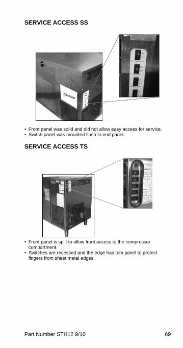
SERVICE ACCESS SS
• Front panel was solid and did not allow easy access for service.• Switch panel was mounted flush to end panel.
SERVICE ACCESS TS
• Front panel is split to allow front access to the compressor compartment.
• Switches are recessed and the edge has trim panel to protect fingers from sheet metal edges.

70 Part Number STH12 9/10
SERVICE ACCESS TS WITH ERC
• Service Switch — (SER) switch, press to send ID on power line network.
• Wink Function — LED flashes “Ion” to indicate wink function. Press program switch (PGM) to disable wink function.
LED Display
Service SwitchProgram Switch
SERPGM
CIRC B
COMP/AGIT CARB A CARB B CIRC A CIRC B
Part Number STH12 9/10 71
Equipment Setup Procedure (Non-ERC)1. Ensure that all valve nozzles are attached to the
valves.
2. Observe pressure of CO2 high pressure tank of 500 psi (34 bar) or more, or bulk CO2 tank of 150 psi or more. Primary regulator set at 90 psi (6 bar) and the secondary regulator set at 35 psi (2.4 bar).
3. Observe the control panel to verify that all pressure gauges are set at correct operating pressures.
4. Check the syrup tanks to make sure a sufficient number of tanks are connected in series to satisfy business volume.
5. Clean syrup inlet and outlet quick disconnects at the same time tanks are replaced. Rinse disconnects in clean potable water.
72 Part Number STH12 9/10
Start-up (Non-ERC)1. Fill the refrigeration unit water bath tank with
water to within 1/2" (1.27 cm) of the top of the overflow tube.
2. Open the manual water shut-off valve to the water cooled condenser (if applicable).
3. Turn ON the rocker switch labeled “Refrigeration” to begin building an ice bank.
4. Turn ON the rocker switch labeled “Agitator”.
NOTE: On TS units 3 & 4 are combined into 1 switch.
5. Ice will begin to form on the evaporator coils in approximately 2 hours.
6. The refrigeration unit will build an ice bank in approximately 4 to 6 hours.
7. If optional CO2/Water Control Panel has been installed on the refrigeration unit, refer to the installation instructions for operation and testing the circuits for leaks.
8. The carbonation circuits “A” and “B,” as well as the syrup circuits must be checked for leaks and possible cross circuits before turning ON the water supply to carbonator pumps.
9. Turn on main water supply. Set incoming regulator to 55 psi on the CO2 panel; 25 psi for the Model 11M root beer system’s internal regulator (must be lower than CO2 supply pressure). Once water is supplied to the unit, air needs to be purged from the carbonator tank. Do so by lifting press relief valve tab until water comes out of relief valve.
10. Turn on main CO2 supply. Set regulator initially to 90 – 100 psi. For the Model 11 Root Beer system, set regulator initially to 26 psi; it can be raised incrementally to 30 psi if there is excessive foaming.
11. Set bag-in-box syrup tank push pressure CO2 regulator to 65 – 70 psi. For the Model 11 Root Beer system, set push pressure CO2 regulator to 35 – 40 psi.
Part Number STH12 9/10 73
PLACING THE CARBONATION SYSTEM IN OPERATION
1. Open the CO2 gas supply valve at CO2 tanks or bulk tank. Adjust the CO2 pressure to 90 psi (6.2 bar).
2. Open relief valve on top of the carbonator tank for 4 seconds to bleed off air in tank.
3. Turn ON the water supply to unit.
4. Turn ON the switch labeled “Carbonator Pump”. Allow carbonator to run and cycle OFF.
5. Activate all valves until a smooth, continuous flow of carbonated water and non-carbonated water appear at the valves.
6. Turn ON switch labeled “Circulator”.
7. Allow at least 1 hour before proceeding to calibration instructions. You may complete the sanitizing instructions during this period.
74 Part Number STH12 9/10
Sequence of Operation (Non-ERC)
PRE-MIX REFRIGERATION UNIT
Ice Bank Is Required
1. Check water bath for full ice bank.
2. The stabilized water bath operating temperature must be maintained at 33°F (0.6°C) to 35°F (1.7°C).
The following is a sequence of operations for the Multiplex Pre-mix Beverage equipment.
1. Once a drink is dispensed, the following will occur:
A. For a Syrup Tank System, the Pre-mix syrup is manually mixed at the store. Pre-mix beverage is then transferred to a holding tank for supply to the Multiplex system.
B. For a Bag-In-Box System, pre-mix syrup is drawn from a Bag-In-Box by means of a gas driven syrup pump.
2. The carbonator pump (stainless) pulls the 5:1 pre-mix out of the 3 gallon holding tank and injects it into the pre-mix carbonator tank where the CO2 pressure is 35 psi (2.4 bar) on the tank.
3. The circulator pump runs continuously and circulates water bath water through the conduit to provide cooling for all drinks.
Part Number STH12 9/10 75
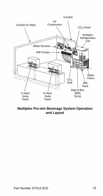
Multiplex Pre-mix Beverage System Operation and Layout
Conduit (In Wall)
6 Valve Soda Tower
8 Valve Soda Tower
Water Booster
Air Compressor
Conduit
CO2 Panel
Multiplex Refrigeration
Unit
CO2 Tank
Bag-In-Box (BIB) Syrup
BIB Rack
Water Filters
BIB Pumps

76 Part Number STH12 9/10
Start-up (with ERC)
PLACING EQUIPMENT IN OPERATIONBefore placing equipment in operation, verify that all requirements for roof mounted Remote Condenser Units (if applicable) have been satisfied. Refer to the instructions on installing the Remote Condenser. Verify proper supply power to unit.
1. Fill the refrigeration unit water bath tank with water to within 1/2" (1.27 cm) of the top of the overflow tube.
2. Open the manual water shut-off valve to the water cooled condenser (if applicable). Refer to “Electronic Control” for control programming sequence.
3. Press “Comp/Agit” to begin building an ice bank.
4. Ice will begin to form on the evaporator coils in approximately 2 hours.
5. The refrigeration unit will build an ice bank in approximately 4 to 6 hours.
6. If optional CO2/Water Control Panel has been installed on the refrigeration unit, refer to the installation instructions for operation and testing the circuits for leaks.
7. The carbonation circuits “A” and “B,” as well as the syrup circuits must be checked for leaks and possible cross circuits before turning ON the water supply to carbonator pumps.
8. Turn on main water supply. Set incoming regulator to 55 psi on the CO2/Water control panel. Once water is supplied to the unit, air needs to be purged from the carbonator tank. Do so by lifting press relief valve tab until water comes out of relief valve.
9. Set bag-in-box syrup tank push pressure CO2 regulator to 60 psi.
Part Number STH12 9/10 77
PLACING THE SYRUP SYSTEM IN OPERATION1. Open the CO2 gas supply valve at CO2 tanks or
bulk tank. Adjust the CO2 pressure to 90 psi (6.2 bar).
2. Open relief valve on top of the carbonator tank for 4 seconds to bleed off air in tank.
3. Verify the water supply to unit is on.
4. Press the switch labeled “Carb A” (and B if applicable). Allow carbonator to run and cycle OFF.
5. Press the switch labeled “CIRC A” (and “CIRC B” if applicable).
6. Activate all vales until a smooth, continuous flow or carbonated water and non-carbonated water appear at the valves.
7. Allow at least 1 hour before proceeding to calibration instructions. You may complete the sanitizing instructions during this period.
78 Part Number STH12 9/10
Sequence of Operation (with ERC)
ELECTRONIC CONTROL
Prerequisites
• Potable water must be connected to the carbonator pump circuit.
• The ice bank water bath water must cover the evaporator. The compressor will not start unless the ice bank control probes are immersed in water.
• CO2 must be supplied.
Initial Power-up
The control has a 30-second delay when power is connected, or disconnected and reconnected. The display will show Pd30 - power delay and 30 seconds left in the countdown cycle.
Normal Two Circuit Operation
Pressing the COMP/AGIT button will start the water bath agitator immediately and initiate the 180 second compressor delay. The display will show Cd99 (compressor delay & 99 seconds) and will start to count down from 99 seconds after the first 81 seconds have elapsed. After 180 seconds the compressor and condenser fan motor energize and the COMP/AGIT LED flashes. Pressing the CARB A and CARB B buttons will power the carbonator tank liquid level control. The corresponding LED flashes to indicate the pump is running. Pressing the CIRC A & CIRC B buttons will immediately energize the circulating pumps and energize the LED constantly. The display will show the circulating temperature and show the A circuit. When two circuits are used the readout will alternate between A and B circuits every 5 seconds.
The compressor and condenser fan will continue to run until ice contacts the ice bank control probe closest to the evaporator. When ice contacts the probe, the COMP/AGIT LED lights constantly and the compressor and condenser fan motor de-energize.
As the ice bank melts, the ice bank control probe will lose contact with the ice; the LED will flash and the compressor and condenser fan motor will restart. This cycle will repeat as required depending on load.
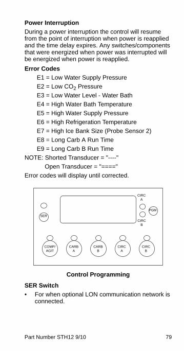
Part Number STH12 9/10 79
Power Interruption
During a power interruption the control will resume from the point of interruption when power is reapplied and the time delay expires. Any switches/components that were energized when power was interrupted will be energized when power is reapplied.
Error Codes
E1 = Low Water Supply Pressure
E2 = Low CO2 Pressure
E3 = Low Water Level - Water Bath
E4 = High Water Bath Temperature
E5 = High Water Supply Pressure
E6 = High Refrigeration Temperature
E7 = High Ice Bank Size (Probe Sensor 2)
E8 = Long Carb A Run Time
E9 = Long Carb B Run Time
NOTE: Shorted Transducer = "----"
Open Transducer = "===="
Error codes will display until corrected.
Control Programming
SER Switch
• For when optional LON communication network is connected.
SER
PGM
CIRC B
CIRC A
COMP/AGIT
CARB A
CARB B
CIRC A
CIRC B
80 Part Number STH12 9/10
PGM Switch
• Used to enter and exit programming modes.
• Press PGM Switch F000 will display
• Press and hold Carb A switch — Display will indicate Water Bath Temperature
• Press and hold Circ A switch — Display will indicate Discharge Temperature
• Press and hold Circ B switch — Display will indicate Suction Temperature
• Press PGM Switch P000 will display
• Press and hold Carb A switch — Display will indicate Water Pressure
• Press and hold Carb B switch — Display will indicate CO2 Pressure
Press and hold PGM switch for 3 seconds to save settings and exit program mode.
Program Mode 1
To enter, press and hold switch for 3 seconds.
• 0001 will display indicating Mode 1
• Wait 3 seconds — C000 will display
• Press and hold Carb A switch — Display will indicate one of the following:
• CA00 — Low and High Probes are open (carbonator motor is energized)
• CA11 — Low and High Probes are closed (carbonator motor is de-energized)
• CA01 — Low Probe closed (Motor will still be on)
Part Number STH12 9/10 81
• Press and hold Carb B switch — Display will indicate one of the following:
• Cb00 — Low and High Probes are open (carbonator motor is energized)
• Cb11 — Low and High Probes are closed (carbonator motor is de-energized)
• Cb01 — Low Probe closed (Motor will still be on)
• Press and hold COMP/AGIT switch — Display will indicate one of the following:
• CL 0 — Water level low
• CL 1 — Water level OK
Program Mode 2
Add circulation pumps C & D.
• Press PGM button for 3 seconds — Display shows 0001.
• Press PGM button — Display shows 0002 program mode 2.
• Wait 3 seconds — Display shows -002 = Factory default setting.
• Pressing CIRC A button energizes/de-energizes pump A
• Pressing CIRC B button energizes/de-energizes pump B
• Program CIRC C — Press CARB A button – Display shows -102 = Carb A button energizes/de-energizes pump C
• Program CIRC D — Press CARB B button - Display shows -012 = Carb B button energizes/de-energizes pump D
Press and hold PGM switch for 3 seconds to save settings and exit program mode.
82 Part Number STH12 9/10
Program Mode 4
Temporarily cancel display of error codes. Cancelling the error codes allows circulating glycol temperatures to be displayed until the error can be corrected.
• Press PGM button for 3 seconds — Display shows 0001.
• Press PGM button three times — Display shows 0004 program mode 4.
• Wait 3 seconds — Display shows -004 = All error codes will be displayed during run mode.
• Press COMP/AGIT button once — Display shows ---4 = error codes will not be displayed during run mode.
NOTE: Disconnecting and reconnecting main power will reset the control board to the factory setting -004 = Error codes will be displayed in the run mode.
Equipment Setup Procedure (with ERC)1. Ensure that all valve nozzles are attached to the
valves.
2. Observe pressure of CO2 high pressure tank of 500 psi (34 bar) or more, or bulk CO2 tank of 150 psi or more. Primary regulator set at 90 psi (6 bar) and the secondary regulator set at 35 psi (2.4 bar).
3. Observe the control panel to verify that all pressure gauges are set at correct operating pressures.
4. Check the syrup tanks or BIB to make sure a sufficient number of tanks are connected in series to satisfy business volume.
5. Clean syrup inlet and outlet quick disconnects at the same time tanks are replaced. Rinse disconnects in clean potable water.

Part Number STH12 9/10 83
Multiplex Electronic Refrigeration Control (ERC) Programming
SU
PP
LY P
OW
ER
ON
AG
ITA
TO
R
CO
ME
S O
N
CO
NS
TAN
TLY
CO
MP
RE
SS
OR
D
ELA
Y S
HO
WS
“C
d99
” A
ND
C
OU
NT
S D
OW
N
TO
“C
d00”
PO
WE
R U
P D
EL
AY
S
HO
WS
“P
d30
” A
ND
CO
UN
TS
D
OW
N T
O “
Pd0
0”
CO
MP
RE
SS
OR
C
OM
ES
ON
AF
TE
R
DE
LAY,
IF
CO
NT
RO
L C
IRC
UIT
R
EQ
UIR
ES
CO
MP
/AG
IT
SW
ITC
H O
N
YE
S
NO
YE
S
NO
ER
RO
R
CO
DE
(S)
NO
RM
AL
RU
N
MO
DE
DIS
PLA
Y
SH
OW
S C
IRC
W
AT
ER
TE
MP
(S)
OR
WA
TE
R B
AT
H
TE
MP
IN B
EE
R
PR
ES
S A
NY
S
WIT
CH
TO
T
UR
N O
N L
OA
D
OR
LO
AD
C
ON
TR
OL
CIR
CU
IT
RE
SP
EC
TIV
E
LE
D C
OM
ES
ON
C
ON
STA
NT,
F
LAS
HE
S I
F
LOA
D C
ON
TR
OL
CIR
CU
IT O
N
ER
RO
R C
OD
E
DIS
PLA
YS
TIL
L C
OR
RE
CT
ED
M
ULT
IPLE
E
RR
OR
S C
YC
LE
PG
M M
OD
E 4
O
VE
RR
IDE
S
E1
= L
OW
WA
TE
R P
RE
SS
E2
= L
OW
CO
2 P
RE
SS
E3
= L
OW
WA
TE
R B
AT
H L
EV
EL
E4
= H
IGH
WA
TE
R B
AT
H T
EM
PE
5 =
HIG
H W
AT
ER
PR
ES
SE
6 =
HIG
H R
EF
RIG
ER
AT
ION
TE
MP
E7
= L
AR
GE
IC
E B
AN
KE
8 =
LO
NG
CA
RB
A R
UN
TIM
EE
9 =
LO
NG
CA
RB
B R
UN
TIM
E“=
==
” =
OP
EN
“__
_”
=S
HO
RT
EN
TE
R P
RO
GR
AM
MO
DE
EX
IT P
RO
GR
AM
MO
DE
PR
OG
RA
M M
OD
ET
O E
NT
ER
, PR
ES
S A
ND
HO
LD P
GM
SW
ITC
H F
OR
MIN
IMU
M O
F 3
SE
CO
ND
S. D
ISP
LAY
SH
OW
S “
000
1”T
O E
XIT
, PR
ES
S A
ND
HO
LD P
GM
SW
ITC
H F
OR
MIN
IMU
M O
F 3
SE
CO
ND
S. D
ISP
LA
Y S
HO
WS
NO
RM
AL
RU
N M
OD
E
PR
OG
RA
M M
OD
E 1
PR
OG
RA
M M
OD
E 2
PR
OG
RA
M M
OD
E 3
PR
OG
RA
M M
OD
E 4

84 Part Number STH12 9/10
Equipment Close Procedure — All Units1. Clean the underside of the dispensing tower
around the nozzle area with a clean damp towel.
2. Pour at least 60 oz (1.8 liters) of warm water down the drain openings.
PR
OG
RA
M M
OD
E 1
RE
AD
CO
ND
UC
TIV
ITY,
T
EM
PE
RA
TU
RE
, P
RE
SS
UR
E C
HA
NG
E
UN
ITS
WA
IT 3
SE
CO
ND
SD
ISP
LAY
SH
OW
S “
C00
0”
PR
OG
RA
M M
OD
E 2
PR
OG
RA
M O
NE
OR
TW
O M
OR
E
CIR
CU
LAT
ING
PU
MP
S
PR
ES
S P
GM
SW
ITC
H O
NC
E IN
LE
SS
TH
AN
3 S
EC
ON
DS
D
ISP
LA
Y “
0002
”, W
AIT
TH
RE
E
SE
CO
ND
S D
ISP
LAY
“-0
02”
PR
OG
RA
M M
OD
E 3
PR
OG
RA
M T
EM
PE
RA
TU
RE
C
ON
TR
OL
OF
WA
TE
R B
AT
H
(BE
ER
)
PR
ES
S P
GM
SW
ITC
H T
WIC
E
IN L
ES
S T
HA
N 3
SE
CO
ND
S,
DIS
PLA
Y “
000
3”, W
AIT
T
HR
EE
SE
CO
ND
S D
ISP
LA
Y
“-00
3”
PR
OG
RA
M M
OD
E 4
TE
MP
OR
AR
ILY
DIS
AB
LE
E
RR
OR
S
PR
ES
S P
GM
SW
ITC
H
TH
RE
E T
IME
S I
N L
ES
S
TH
AN
TH
RE
E S
EC
ON
DS
DIS
PLA
Y “
0004
”, W
AIT
T
HR
EE
SE
CO
ND
S
DIS
PLA
Y “
-004
”
PR
ES
S C
OM
P/A
GIT
S
WIT
CH
, DIS
PLA
Y
SH
OW
S “
---4
” IN
DIC
AT
ING
ER
RO
R
CO
DE
S W
ILL
BE
D
ISA
BLE
D U
NT
IL N
EX
T
PO
WE
R O
N/O
FF
S
EQ
UE
NC
E
TO
CH
AN
GE
UN
ITS
WH
EN
“F
000”
PR
ES
S
CO
MP
/AG
IT S
WIT
CH
O
NC
E T
O C
HA
NG
E
TE
MP
ER
AT
UR
E U
NIT
S
TO
CE
NT
IGR
AD
E
“FC
00”
WH
EN
“P
000”
PR
ES
S
CO
MP
/AG
IT S
WIT
CH
O
NC
E T
O C
HA
NG
E
PR
ES
SU
RE
UN
ITS
TO
B
AR
“F
b00”
PR
ES
S C
OM
P/A
GIT
SW
ITC
H
ON
CE
, DIS
PLA
Y =
“1X
X3”
WH
ER
E
XX
=S
ET
PO
INT
TE
MP
ER
AT
UR
E
(DE
FAU
LT =
“1
273”
) (D
IFF
ER
EN
TIA
L F
IXE
D A
T 2
° A
BO
VE
SE
T P
OIN
T)
PR
ES
S C
IRC
A S
WIT
CH
T
O L
OW
ER
SE
T P
OIN
T
TE
MP
ER
AT
UR
E
PR
ES
S C
IRC
B S
WIT
CH
T
O R
AIS
E S
ET
PO
INT
T
EM
PE
RA
TU
RE
NO
TE
:S
ET
PO
INT
=
CO
MP
RE
SS
OR
OF
F
DIF
FE
RE
NT
IAL
IS F
IXE
D
AT
2°F
AB
OV
E S
ET
PO
INT
C
OM
PR
ES
SO
R O
N
PR
ES
S C
AR
B A
SW
ITC
H T
O
CO
NV
ER
T C
AR
B A
MO
TO
R
TO
CIR
C M
OT
OR
“-
102”
PR
ES
S C
AR
B B
SW
ITC
H T
O
CO
NV
ER
T C
AR
B B
MO
TO
R
TO
CIR
C M
OT
OR
“-
112”
“F00
00”
(TE
MP
ER
AT
UR
E)
PR
ES
S C
AR
B A
SW
ITC
H
TO
SH
OW
WA
TE
R B
AT
H
TE
MP
PR
ES
S C
IRC
A S
WIT
CH
TO
S
HO
W D
ISC
HA
RG
E T
EM
PP
RE
SS
CIR
C B
SW
ITC
H T
O
SH
OW
SU
CT
ION
TE
MP
PRES
S PG
M S
WIT
CH
ON
CE
“P00
0” (
PR
ES
SU
RE
)
PR
ES
S C
AR
B A
SW
ITC
H
TO
SH
OW
WA
TE
R S
UP
PLY
P
RE
SS
UR
EP
RE
SS
CA
RB
B S
WIT
CH
T
O S
HO
W C
O2
PR
ES
SU
RE
“C00
0”
(CO
ND
UC
TIV
ITY
)
PR
ES
S C
OM
P/A
GIT
S
WIT
CH
TO
SH
OW
ICE
B
AN
K P
RO
BE
“CC
11”
= N
O IC
E
CO
MP
RE
SS
OR
ON
; “C
C10
” =
IC
E O
N L
OW
SE
NS
OR
C
OM
PR
ES
SO
R O
FF
“CC
00”
= IC
E B
AN
K T
OO
LA
RG
E (
E7
)
PR
ES
S C
AR
B A
SW
ITC
H
TO
SH
OW
LLC
PR
OB
E“C
A00
” =
NO
WA
TE
RC
AR
B A
MO
TO
R O
N“C
A01
” =
LO
W S
EN
SO
RIN
WA
TE
R, M
OT
OR
ON
“CA
11”
= L
OW
& H
IGH
S
EN
SO
R IN
WA
TE
R,
MO
TO
R O
FF
R
EP
EA
T A
BO
VE
FO
R
CA
RB
B S
WIT
CH
“C
bXX
”
PR
ES
S C
IRC
A S
WIT
CH
T
O S
HO
W W
AT
ER
LE
VE
L P
RO
BE
“C
L 1”
= W
AT
ER
“CL
0” =
LO
W W
AT
ER
(E
3)
PRES
S PG
M S
WIT
CH
ON
CE
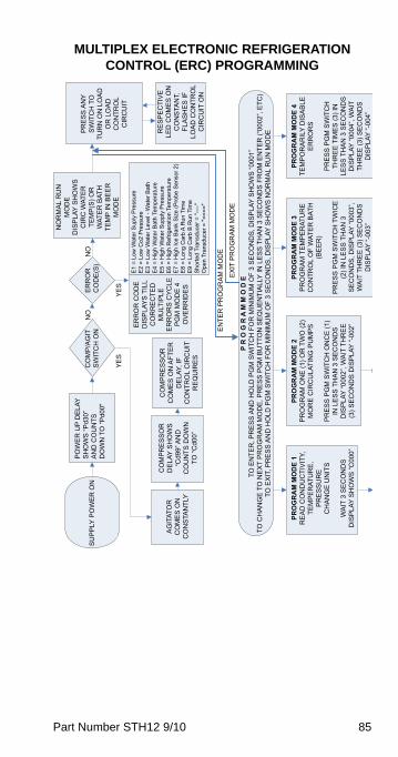
Part Number STH12 9/10 85
MULTIPLEX ELECTRONIC REFRIGERATION CONTROL (ERC) PROGRAMMING
PO
WE
R U
P D
ELA
YS
HO
WS
“Pd3
0”A
ND
CO
UN
TSD
OW
N T
O “P
d00"
SU
PP
LY P
OW
ER
ON
NO
RM
AL
RU
NM
OD
ED
ISP
LAY
SH
OW
SC
IRC
WAT
ER
TEM
P(S
) OR
WAT
ER
BAT
HTE
MP
IN B
EE
RM
OD
E
CO
MP
/AG
ITS
WIT
CH
ON
NO
YE
S
P R
O G
R A
M M
O D
ETO
EN
TER
, PR
ES
S A
ND
HO
LD P
GM
SW
ITC
H F
OR
MIN
IMU
M O
F 3
SE
CO
ND
S, D
ISP
LAY
SH
OW
S “0
001”
TO C
HA
NG
E T
O N
EX
T P
RO
GR
AM
MO
DE
, PR
ES
S P
GM
BU
TTO
N S
EQ
UE
NTI
ALL
Y IN
LE
SS
TH
AN
3 S
EC
ON
DS
FR
OM
EN
TER
(“00
02”,
ETC
)TO
EX
IT, P
RE
SS
AN
D H
OLD
PG
M S
WIT
CH
FO
R M
INIM
UM
OF
3 S
EC
ON
DS
, DIS
PLA
Y S
HO
WS
NO
RM
AL
RU
N M
OD
ERE
SP
EC
TIV
ELE
D C
OM
ES
ON
CO
NS
TAN
T,FL
AS
HE
S IF
LOA
D C
ON
TRO
LC
IRC
UIT
ON
PR
ES
S A
NY
SW
ITC
H T
OTU
RN
ON
LO
AD
OR
LO
AD
CO
NTR
OL
CIR
CU
IT
AG
ITAT
OR
CO
ME
S O
NC
ON
STA
NTL
Y
CO
MP
RE
SS
OR
CO
ME
S O
N A
FTE
RD
ELA
Y, IF
CO
NTR
OL
CIR
CU
ITR
EQ
UIR
ES
EN
TER
PR
OG
RA
M M
OD
E
EX
IT P
RO
GR
AM
MO
DE
PRO
GR
AM
MO
DE
4TE
MP
OR
AR
ILY
DIS
AB
LEE
RR
OR
S
PR
ES
S P
GM
SW
ITC
HTH
RE
E T
IME
S (3
) IN
LES
S T
HA
N 3
SE
CO
ND
SD
ISP
LAY
“000
4”, W
AIT
THR
EE
(3) S
EC
ON
DS
DIS
PLA
Y “-
004”
PRO
GR
AM
MO
DE
3P
RO
GR
AM
TE
MP
ER
ATU
RE
CO
NTR
OL
OF
WAT
ER
BAT
H(B
EE
R)
PR
ES
S P
GM
SW
ITC
H T
WIC
E(2
) IN
LE
SS
TH
AN
3S
EC
ON
DS
, DIS
PLA
Y “0
003”
,W
AIT
TH
RE
E (3
) SE
CO
ND
SD
ISP
LAY
“-00
3”
PRO
GR
AM
MO
DE
2P
RO
GR
AM
ON
E (1
) OR
TW
O (2
)M
OR
E C
IRC
ULA
TIN
G P
UM
PS
PR
ES
S P
GM
SW
ITC
H O
NC
E (1
)IN
LE
SS
TH
AN
3 S
EC
ON
DS
DIS
PLA
Y “0
002”
, WA
IT T
HR
EE
(3) S
EC
ON
DS
DIS
PLA
Y “-
002”
PRO
GR
AM
MO
DE
1R
EA
D C
ON
DU
CTI
VIT
Y,TE
MP
ER
ATU
RE
,P
RE
SS
UR
EC
HA
NG
E U
NIT
S
WA
IT 3
SE
CO
ND
SD
ISP
LAY
SH
OW
S “C
000”
CO
MP
RE
SS
OR
DE
LAY
SH
OW
S“C
d99”
AN
DC
OU
NTS
DO
WN
TO “C
d00”
ER
RO
RC
OD
E(S
)N
O
YE
S
ER
RO
R C
OD
ED
ISP
LAY
S T
ILL
CO
RR
EC
TED
MU
LTIP
LEE
RR
OR
S C
YC
LEP
GM
MO
DE
4O
VE
RR
IDE
S
E1
= Lo
w W
ater
Sup
ly P
ress
ure
E2
= Lo
w C
o2 P
ress
ure
E3
= Lo
w W
ater
Lev
el -
Wat
er B
ath
E4
= H
igh
Wat
er B
ath
Tem
pera
ture
E5
= H
igh
Wat
er S
uppl
y P
ress
ure
E6
= H
igh
Ref
riger
atio
n Te
mpe
ratu
reE
7 =
Hig
h Ic
e B
ank
Siz
e (P
robe
Sen
sor 2
)E
8 =
Long
Car
b A
Run
Tim
eE
9 =
Long
Car
b B
Run
Tim
eS
horte
d Tr
ansd
ucer
= "-
---"
Ope
n Tr
ansd
ucer
= "=
==="
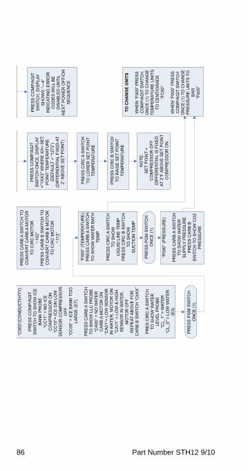
86 Part Number STH12 9/10
“C00
0”(C
ON
DU
CTI
VIT
Y)
PR
ES
S C
OM
P/A
GIT
SW
ITC
H T
O S
HO
W IC
EB
AN
K P
RO
BE
“CC
11” =
NO
ICE
CO
MP
RE
SS
OR
ON
“CC
10”=
ICE
ON
LO
WS
EN
SO
R C
OM
PR
ES
SO
RO
FF“C
C00
” = IC
E B
AN
K T
OO
LAR
GE
(E7)
PR
ES
S C
AR
B A
SW
ITC
HTO
SH
OW
LLC
PR
OB
E“C
A00
” = N
O W
ATE
RC
AR
B A
MO
TOR
ON
“CA
01”=
LO
W S
EN
SO
RIN
WAT
ER
, MO
TOR
ON
“CA
11” =
LO
W &
HIG
HS
EN
SO
R IN
WAT
ER
,M
OTO
R O
FFR
EP
EAT
AB
OV
E F
OR
CA
RB
B S
WIT
CH
“CbX
X”
PR
ES
CIR
C A
SW
ITC
HTO
SH
OW
WAT
ER
LEV
EL
PR
OB
E“C
L_1”
= W
ATE
R“C
L_0”
= L
OW
WAT
ER
(E3)
PR
ES
S C
OM
P/A
GIT
SW
ITC
H, D
ISP
LAY
SH
OW
S “-
--4”
IND
ICAT
ING
ER
RO
RC
OD
ES
WIL
L B
ED
ISA
BLE
D U
NTI
LN
EX
T P
OW
ER
OFF
/ON
SE
QU
EN
CE
“F00
0” (T
EM
PE
RAT
UR
E)
PR
ES
S C
AR
B A
SW
ITC
HTO
SH
OW
WAT
ER
BAT
HTE
MP
PR
ES
S C
IRC
A S
WIT
CH
TO S
HO
WLI
QU
ID L
INE
TE
MP
PR
ES
S C
IRC
B S
WIT
CH
TO S
HO
WS
UC
TIO
N T
EM
P
“P00
0” (P
RE
SS
UR
E)
PR
ES
S C
AR
B A
SW
ITC
HTO
SH
OW
WAT
ER
SU
PP
LY P
RE
SS
UR
EP
RE
SS
CA
RB
BS
WIT
CH
TO
SH
OW
CO
2P
RE
SS
UR
E
PR
ES
S C
OM
P/A
GIT
SW
ITC
H O
NC
E, D
ISP
LAY
=”1X
X3"
WH
ER
E X
X=
SE
TP
OIN
T TE
MP
ER
ATU
RE
(DE
FAU
LT =
“127
3”)
(DIF
FER
EN
TIA
L FI
XE
D A
T2°
AB
OV
E S
ET
PO
INT)
PR
ES
S C
IRC
A S
WIT
CH
TO L
OW
ER
SE
T P
OIN
TTE
MP
ER
ATU
RE
PR
ES
S C
IRC
B S
WIT
CH
TO R
AIS
E S
ET
PO
INT
TEM
PE
RAT
UR
E
NO
TE:
SE
T P
OIN
T =
CO
MP
RE
SS
OR
OFF
DIF
FER
EN
TIA
L IS
FIX
ED
AT 2
°F A
BO
VE
SE
T P
OIN
TC
OM
PR
ES
SO
R O
N
PR
ES
S C
AR
B A
SW
ITC
H T
OC
ON
VE
RT
CA
RB
A M
OTO
RTO
CIR
C M
OTO
R“-
102”
PR
ES
S C
AR
B B
SW
ITC
H T
OC
ON
VE
RT
CA
RB
B M
OTO
RTO
CIR
C M
OTO
R“-
112”
PR
ES
S P
GM
SW
ITC
HO
NC
E (1
)
PR
ES
S P
GM
SW
ITC
HO
NC
E (1
)
TO C
HA
NG
E U
NIT
S
WH
EN
“F00
0” P
RE
SS
CO
MP
/AG
IT S
WIT
CH
ON
CE
(1) T
O C
HA
NG
ETE
MP
ER
ATU
RE
UN
ITS
TO C
EN
TIG
RA
DE
“FC
00”
WH
EN
“P00
0” P
RE
SS
CO
MP
/AG
IT S
WIT
CH
ON
CE
(1) T
O C
HA
NG
EP
RE
SS
UR
E U
NIT
S T
OB
AR
“Fb0
0”
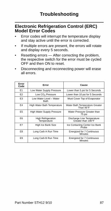
Part Number STH12 9/10 87
Troubleshooting
Electronic Refrigeration Control (ERC) Model Error Codes• Error codes will interrupt the temperature display
and stay active until the error is corrected.
• If multiple errors are present, the errors will rotate and display every 5 seconds.
• Resetting errors — After correcting the problem, the respective switch for the error must be cycled OFF and then ON to reset.
• Disconnecting and reconnecting power will erase all errors.
Error Code Error Cause
E1 Low Water Supply Pressure Lower than 5 psi for 5 Seconds
E2 Low CO2 Pressure Lower than 10 psi for 5 Seconds
E3 Low Water Level – Water Bath
Must Cover Top of Evaporator
E4 High Water Bath Temperature Water Bath Temperature Greater Than 45°F
E5 High Water Supply Pressure Water Pressure Greater than 75 psi
E6 High Refrigeration Temperature
Discharge Line Temperature Greater than 190°F
E7 High Ice Bank Size Ice Contacting Center Ice Bank Probe
E8 Long Carb A Run Time Energized for 7 Continuous Minutes
E9 Long Carb B Run Time Energized for 7 Continuous Minutes
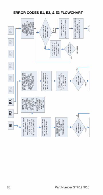
88 Part Number STH12 9/10
ERROR CODES E1, E2, & E3 FLOWCHARTEI
YES
NO
NO
RM
ALLY
CAU
SED
BY
WA
TER
P
RE
SS
UR
E <
5 P
SI
FOR
5 S
ECO
ND
SM
US
T S
TAY
AB
OV
E
10 P
SI T
O C
OR
REC
T
E3E4
E5E6
E7E8
E9E2
NO
YES
NO
NO
YES
YES
/EN
D
NO
TE: T
HAT
A
LL C
AR
B
MO
TOR
S AN
D
ALL
CIR
C
MO
TOR
S W
ILL
GO
OFF
, WIT
H
THIS
ER
RO
RC
OM
PRES
SOR
AN
D
AG
ITA
TOR
STA
Y O
N
NO
RM
ALLY
CAU
SED
B
Y C
O2
PR
ES
SU
RE
<1
0 P
SI F
OR
5
SE
CO
ND
S M
US
T S
TAY
AB
OV
E 1
5 PS
I TO
CO
RR
ECT
NO
RM
ALLY
CA
US
ED
BY
WA
TER
LE
VE
L IN
W
ATE
R B
ATH
B
ELO
W P
RO
BE
C
ON
DU
CTO
RS
GO
INTO
PR
OG
RA
M
MO
DE
1 P
RES
SU
RE
R
EA
DO
UT
“P00
0”
GO
INTO
PR
OG
RA
M
MO
DE
1 P
RES
SU
RE
R
EA
DO
UT
“P00
0”
PR
ES
S C
AR
B A
BU
TTO
N T
O V
ERIF
Y W
ATE
R
PR
ES
SU
RE
“PX
XX
”
DIS
PLA
Y P
RE
SS
UR
E>1
5 P
SI
PR
ES
S C
AR
B B
BU
TTO
N T
O V
ERIF
Y C
O2
PR
ES
SU
RE
“P
XX
X” P
SI
DIS
PLA
Y P
RE
SS
UR
E>2
0PS
I
VE
RIF
Y W
ATE
R
LEV
EL
AB
OV
E P
RO
BE
TIP
S
ADD
WA
TER
TO
W
ATE
R B
ATH
A
BO
VE
LEV
EL
OF
PR
OB
E T
IPS
GO
INTO
PR
OG
RA
M
MO
DE
1
CO
ND
UC
TIV
ITY“
C00
0”E3
ER
RO
R
GO
ES
OFF
PR
ES
S C
IRC
A B
UTT
ON
TO
VE
RIF
Y C
ON
DU
CTI
VIT
Y“C
L_X”
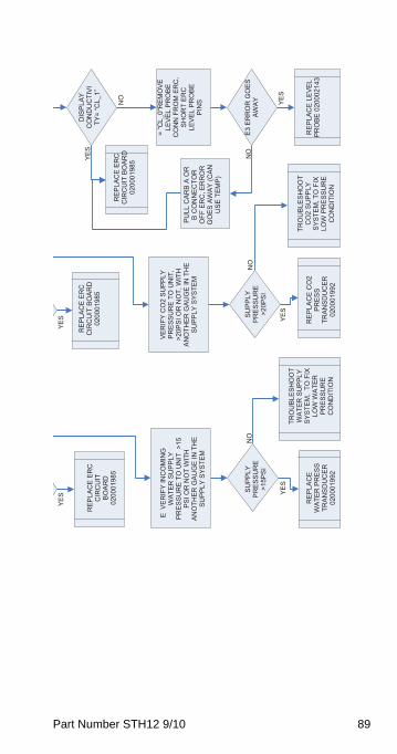
Part Number STH12 9/10 89
VE
RIF
Y IN
CO
MIN
G
WA
TER
SU
PPLY
P
RE
SS
UR
E T
O U
NIT
>15
PS
I OR
NO
T W
ITH
AN
OTH
ER G
AUG
E IN
TH
E S
UP
PLY
SYS
TEM
E
RE
PLA
CE
ER
C
CIR
CU
IT
BOAR
D02
0001
985
YES
NO
YES
NO
YES
YES
NO
YES
NO
YES
RE
PLA
CE
ER
C
CIR
CU
IT B
OAR
D
0200
0198
5
RE
PLA
CE
ER
C
CIR
CU
IT B
OAR
D
0200
0198
5
SU
PP
LY
PR
ES
SU
RE
>15P
SI
SU
PP
LY
PR
ES
SU
RE
>20P
SI
RE
PLA
CE
WA
TER
PR
ES
S
TRAN
SDU
CER
0200
0199
2
TRO
UB
LES
HO
OT
WA
TER
SU
PPLY
S
YSTE
M,
TO F
IX
LOW
WA
TER
P
RE
SS
UR
EC
ON
DIT
ION
RE
PLA
CE
CO
2 P
RE
SS
TRAN
SDU
CER
0200
0199
2
TRO
UB
LES
HO
OT
CO
2 S
UP
PLY
S
YSTE
M, T
O F
IX
LOW
PR
ES
SU
RE
CO
ND
ITIO
N
DIS
PLA
Y C
ON
DU
CTI
VITY
= “C
L_1”
= “C
L_0"
RE
MO
VE
LE
VE
L P
RO
BE
CO
NN
FR
OM
ER
C,
SHO
RT
ERC
LE
VE
L P
RO
BE
PIN
S
VE
RIF
Y C
O2
SU
PPLY
P
RE
SS
UR
E T
O U
NIT
, >2
0PS
I OR
NO
T, W
ITH
AN
OTH
ER G
AUG
E IN
TH
E S
UP
PLY
SYS
TEM
PU
LL C
ARB
A O
R
B C
ON
NEC
TOR
O
FF E
RC
, ER
RO
R
GO
ES
AW
AY
(CAN
U
SE
TE
MP
)
E3 E
RR
OR
GO
ES
AWA
Y
RE
PLA
CE
LE
VEL
PR
OB
E 0
2000
2143
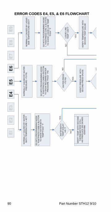
90 Part Number STH12 9/10
ERROR CODES E4, E5, & E6 FLOWCHARTEI
E2E3
E4E5
E6E7
E8E9
NO
RM
ALLY
CAU
SED
BY
WA
TER
B
ATH
TE
MP
ER
ATU
RE
> 4
5°F
NO
RM
ALLY
CAU
SED
BY
WA
TER
P
RE
SS
UR
E >
75 P
SI,
NO
RM
ALLY
CAU
SED
BY
LIQ
UID
S
IDE
TE
MP
ER
ATU
RE
>200
°F
NO
YES
GO
INTO
PR
OG
RA
MM
ING
MO
DE
1, “F
000”
PR
ES
S C
AR
B A
BU
TTO
N
TO S
HO
W W
ATE
R B
ATH
TE
MP
“FX
XX
” °F
GO
INTO
PR
OG
RA
MM
ING
MO
DE
1, “P
000”
PR
ESS
CA
RB
A B
UTT
ON
TO
SH
OW
INC
OM
ING
WA
TER
P
RE
SS
UR
E “P
XX
X”
PS
I
GO
INTO
PR
OG
RA
MM
ING
MO
DE
1, “F
000”
PR
ES
S C
IRC
A B
UTT
ON
TO
SH
OW
LIQ
UID
LIN
E T
EM
P “F
XX
X” °
F
WA
TER
BAT
H
TEM
P D
ISLA
Y N
O
YES
WA
TER
PR
ES
S
>75
PSI
N
O>4
5 °F
NO
YES
LIQ
UID
LIN
E TE
MP
>20
0°F
VE
RIF
Y TE
MP
WIT
H S
EC
ON
D
THER
MO
MET
ERIF
STI
LL
<45°
FRE
PLA
CE
ER
C B
OA
RD
V
ER
IFY
PR
ES
SU
RE
WIT
H
SE
CO
ND
PR
ES
S G
AU
GE
VE
RIF
Y TE
MPE
RAT
UR
E W
ITH
SE
CO
ND
TEM
P G
AUG
E 02
0001
985
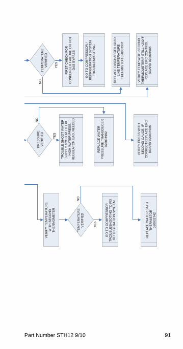
Part Number STH12 9/10 91
NO
YES
YES
NO
YES
NO
PR
ES
SU
RE
VE
RIF
IED
TE
MPE
RAT
UR
EV
ER
IFIE
D
VE
RIF
Y TE
MP
ER
ATU
RE
W
ITH
SEC
ON
D
THER
MO
MET
ER
TRO
UBL
E SH
OO
T W
ATE
R
SU
PP
LY S
YSTE
M T
O F
IX.
HIG
H W
ATE
R P
RES
S,
RE
GU
LATO
R B
AD
, NE
ED
ED
FIR
ST C
HEC
K FO
R
CO
ND
ENSE
R F
AILU
RE
OR
HO
T G
AS
BYP
AS
S
TEM
PER
ATU
RE
VE
RIF
IED
G
O T
O C
OM
PR
ESS
OR
/ R
EFR
IGE
RA
TIO
N S
YSTE
M
TRO
UB
LES
HO
OTI
NG
RE
PLA
CE
WA
TER
PR
ESSU
RE
TRAN
SDU
CER
02
0001
992
GO
TO
CO
MP
RE
SSO
R
TRO
UB
LES
HO
OTI
NG
TO
FIX
R
EFR
IGE
RA
TIO
N S
YSTE
M
RE
PLA
CE
DIS
CH
ARG
E/L
IQU
ID
LIN
E T
EM
PE
RA
TUR
E
THE
RM
ISTO
R 0
2000
1991
VE
RIF
Y TE
MP
WIT
H S
EC
ON
D
THE
RM
OM
ETE
RIF
STI
LL <
200°
F R
EPLA
CE
ERC
CO
NTR
OL
BO
AR
D 0
2000
1985
VE
RIF
Y P
RE
SS
WIT
H
SEC
ON
D G
AUG
E, IF
C
OR
REC
TREP
LAC
E ER
C
BO
AR
D 0
2000
1985
R
EP
LAC
E W
ATE
R B
ATH
TH
ERM
ISTO
R
0200
0214
2
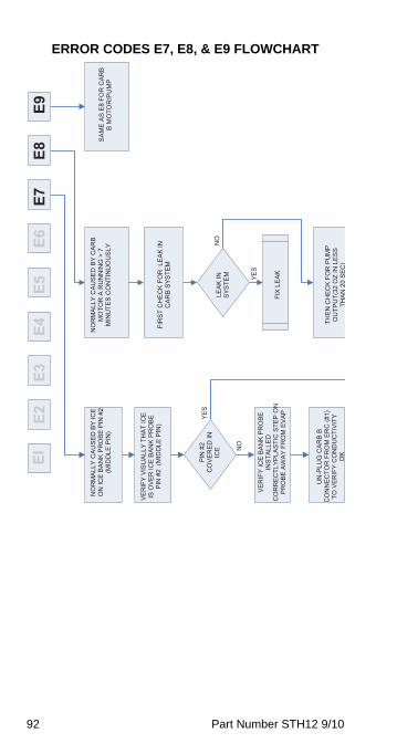
92 Part Number STH12 9/10
ERROR CODES E7, E8, & E9 FLOWCHARTEI
E2E3
E4E5
E6E7
E8E9
NO
RM
ALLY
CAU
SED
BY
CAR
B M
OTO
R A
RU
NN
ING
> 7
M
INU
TES
CO
NTI
NU
OU
SLY
NO
RM
ALLY
CAU
SED
BY
ICE
ON
ICE
BA
NK
PR
OB
E P
IN #
2 (M
IDD
LE P
IN)
SA
ME
AS
E8
FOR
CA
RB
B
MO
TOR
/PU
MP
NO
YES
VE
RIF
Y V
ISU
ALL
Y TH
AT
ICE
IS O
VE
R IC
E B
AN
K P
RO
BE
PIN
#2
(MID
DLE
PIN
) FI
RST
CH
ECK
FOR
LEA
K IN
C
AR
B S
YSTE
M
YES
NO
PIN
#2
CO
VE
RE
D IN
IC
E
LEA
K IN
S
YSTE
M
VE
RIF
Y IC
E B
AN
K P
RO
BE
INS
TALL
ED
CO
RR
EC
TLYP
LAS
TIC
STE
P O
N
PR
OB
E A
WA
Y FR
OM
EV
AP
FI
X L
EAK
UN
-PLU
G C
ARB
B C
ON
NEC
TOR
FR
OM
ER
C (#
1)
TO V
ERIF
Y C
ON
DU
CTI
VIT
Y O
K
THEN
CH
ECK
FOR
PU
MP
OU
TPU
T(32
OZ
IN L
ES
S TH
AN
20S
EC
)
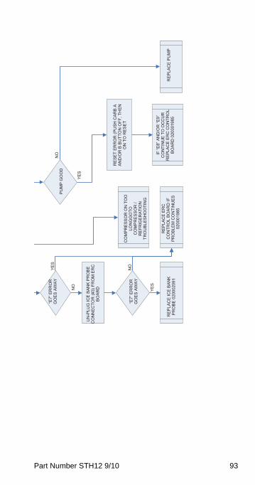
Part Number STH12 9/10 93
NO
NO
YES
YES
YES
NO
“E7”
ER
RO
R
GO
ES
AW
AY
PU
MP
GO
OD
UN
-PLU
G IC
E BA
NK
PRO
BE
CO
NN
ECTO
R (#
3) F
RO
M E
RC
BO
ARD
RE
SE
T E
RR
OR
(PU
SH
CA
RB
A
AND
/OR
B B
UTT
ON
OFF
, TH
EN
ON
TO
RE
SE
T C
OM
PR
ES
SO
R O
N T
OO
LO
NG
GO
TOC
OM
PR
ES
SO
R /
RE
FRIG
ER
ATI
ON
TRO
UB
LES
HO
OTI
NG
“E7”
ER
RO
R
GO
ES
AW
AY
IF “E
8” A
ND
/OR
“E9”
C
ON
TIN
UE
TO O
CC
UR
R
EPLA
CE
ERC
CO
NTR
OL
BO
AR
D 0
2000
1985
RE
PLA
CE
ER
C
CO
NTR
OL
BO
AR
D IF
PR
OBL
EM C
ON
TIN
UES
0200
0198
5
RE
PLA
CE
ICE
BAN
K
PR
OB
E 0
2000
2091
R
EP
LAC
E P
UM
P
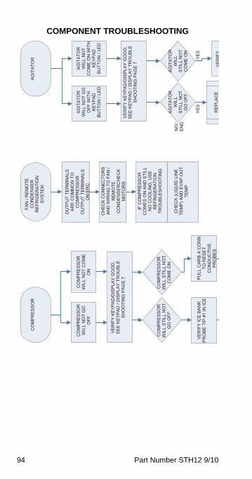
94 Part Number STH12 9/10
COMPONENT TROUBLESHOOTINGFA
N /
REM
OTE
C
ON
DEN
SER
RE
FRIG
ER
ATI
ON
SYS
TEM
AG
ITA
TOR
CO
MP
RE
SS
OR
YES
YES
NO
/EN
D
NO
OU
TPU
T TE
RM
INAL
S AR
E C
OM
MO
N T
O
CO
MP
RE
SS
OR
OU
TPU
T TE
RM
INAL
S O
N E
RC
AG
ITA
TOR
WIL
L N
OT
GO
O
FF W
ITH
K
EYP
AD
BU
TTO
N /
LED
AG
ITA
TOR
WIL
L N
OT
CO
ME
ON
WIT
H
KE
YPA
D
BUTT
ON
/ LE
D
CO
MP
RE
SS
OR
WIL
L N
OT
GO
O
FF
CO
MP
RE
SS
OR
WIL
L N
OT
CO
ME
O
N
CH
ECK
CO
NN
ECTO
RS
AND
WIR
ING
TO
FA
N /
REM
OTE
CO
ND
ENSE
RC
HE
CK
MO
TOR
S
VE
RIF
Y K
EYP
AD
/DIS
PLA
Y G
OO
D,
SE
E K
EYP
AD
/ D
ISP
LAY
TRO
UB
LE
SH
OO
TIN
G P
AG
E 7
VE
RIF
Y K
EYP
AD
/DIS
PLA
Y G
OO
D,
SE
E K
EYP
AD
/ D
ISP
LAY
TRO
UB
LE
SH
OO
TIN
G P
AG
E 7
IF C
OM
PR
ES
SO
R
CO
ME
S O
N A
ND
STI
LL
NO
CO
OLI
NG
, USE
R
EFR
IGE
RA
TIO
NTR
OU
BLES
HO
OTI
NG
CO
MP
RE
SS
OR
WIL
L S
TILL
NO
T G
O O
FF
CO
MP
RE
SS
OR
WIL
L S
TILL
NO
T C
OM
E O
N
AG
ITA
TOR
WIL
L S
TILL
NO
T C
OM
E O
N
AG
ITA
TOR
WIL
L S
TILL
NO
T G
O O
FF
CH
ECK
(LIQ
UID
LIN
E TE
MP
) AN
D E
VAP
OU
T TE
MP
VE
RIF
Y IC
E B
AN
K P
RO
BE
TIP
#1
IN IC
E
PULL
CAR
B A
CO
NN
TO
RE
SE
T C
ON
DU
CTI
VE
PR
OB
ES
RE
PLA
CE
VE
RIF
Y

Part Number STH12 9/10 95
END
NO
NO
NO
YES
NO
YES
ELS
E
PR
OB
ES
RE
PLA
CE
ERC
CO
NTR
OL
BO
AR
D02
0001
985
VE
RIF
Y V
OLT
AG
E O
N E
RC
AG
ITA
TOR
TER
MIN
ALS
PU
LL IC
E B
AN
K C
ON
N O
N E
RC
, C
OM
PR
ES
SO
RS
HO
ULD
GO
OFF
SH
OR
T IC
E B
AN
K
CO
NN
ECTO
R #
3ALL
P
INS
RE
PLA
CE
ICE
B
AN
K P
RO
BE
RE
PLA
CE
HPC
OSW
ITC
H
VER
IFY
HPC
O
SWIT
CH
C
LOSE
DSH
OR
TC
ON
N 1
2
RE
PLA
CE
ICE
B
AN
K P
RO
BE
0200
0209
1IF
NO
V
OLT
AG
E R
EP
LAC
EER
CC
ON
TRO
LBO
ARD
0200
0198
5R
EPLA
CE
ERC
C
ON
TRO
L BD
02
0001
985
VE
RIF
Y V
OLT
AG
E A
T C
OM
P O
UTP
UT
TER
MIN
ALS
ON
ER
C
RE
PLA
CE
ER
C
CO
NTR
OL
BD
0200
0198
5
CH
ECK
CO
NN
ECTO
RS
AND
W
IRIN
G T
O
CO
NTA
CTO
RC
OIL
VER
IFY
WIR
ING
/ C
ON
NEC
TOR
S TO
A
GIT
ATO
RM
OTO
R
RE
PLA
CE
CO
NTA
CTO
RV
ER
IFY
VO
LTA
GE
AT C
ON
TAC
TOR
C
OIL
RE
PLA
CE
AG
ITA
TOR
MO
TOR
VE
RIF
Y P
RO
PE
R
VO
LTA
GE
AT
CO
MP
RE
SS
OR
RE
PLA
CE
CO
MP
RE
SS
OR
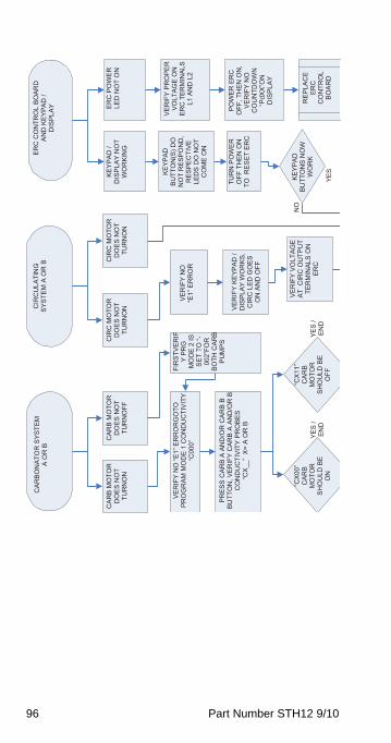
96 Part Number STH12 9/10
CIR
CU
LATI
NG
S
YSTE
M A
OR
B
ERC
CO
NTR
OL
BOAR
D
AN
D K
EYP
AD
/
DIS
PLA
Y
CA
RB
ON
ATO
R S
YSTE
M
A O
R B
YES
/ E
ND
CAR
B M
OTO
R
DO
ES
NO
T TU
RN
ON
CAR
B M
OTO
R
DO
ES
NO
T TU
RN
OFF
CIR
C M
OTO
R
DO
ES
NO
T TU
RN
ON
CIR
C M
OTO
R
DO
ES
NO
T TU
RN
ON
KE
YPA
D /
DIS
PLA
Y N
OT
WO
RKI
NG
ERC
PO
WE
R
LED
NO
T O
N
KE
YPA
D
BU
TTO
N(S
) DO
N
OT
RES
PON
D,
RE
SP
EC
TIV
E LE
DS
DO
NO
T C
OM
E O
N
VE
RIF
Y P
RO
PE
R
VO
LTA
GE
ON
ER
C T
ERM
INAL
S L1
AN
D L
2
FIR
STVE
RIF
Y P
RG
M
OD
E 2
IS
SE
T TO
“-00
2”FO
RBO
TH C
ARB
PU
MP
S
VER
IFY
NO
“E1”
ER
RO
RG
OTO
PR
OG
RAM
MO
DE
1 C
ON
DU
CTI
VIT
Y “C
000”
VE
RIF
Y N
O
“E1”
ER
RO
R
PR
ES
S C
AR
B A
AN
D/O
R C
AR
B B
B
UTT
ON
, VE
RIF
Y C
AR
B A
AN
D/O
R B
C
ON
DU
CTI
VIT
Y P
RO
BE
S
YES
NO
POW
ER
ER
C
OFF
, TH
EN O
N,
VE
RIF
Y N
O
CO
UN
TDO
WN
“P
dXX
”ON
D
ISP
LAY
TUR
N P
OW
ER
O
FF T
HEN
ON
TO
RE
SE
T E
RC
VE
RIF
Y K
EYP
AD
/ D
ISP
LAY
WO
RK
S,
CIR
C L
ED G
OES
O
N A
ND
OFF
“CX
__”
X=
A O
R B
VE
RIF
Y V
OLT
AG
E AT
CIR
C O
UTP
UT
TER
MIN
ALS
ON
ER
C
KE
YPA
D
BUTT
ON
S N
OW
W
OR
K
“CX
00”
CAR
BM
OTO
RS
HO
ULD
BE
O
N
“CX
11”
CAR
BM
OTO
RS
HO
ULD
BE
O
FF
RE
PLA
CE
ERC
CO
NTR
OL
BOAR
D
YES
/ E
ND
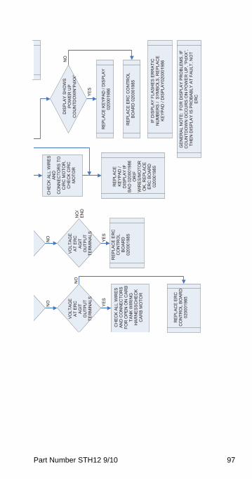
Part Number STH12 9/10 97
NO
NO
YES
NO
CH
EC
K A
LL W
IRES
AN
DC
ON
NEC
TOR
S TO
C
IRC
MO
TOR
, C
HEC
K C
IRC
M
OTO
R
DIS
PLA
Y S
HO
WS
POW
ER
UP
CO
UN
TDO
WN
“PdX
X”
VO
LTA
GE
AT
ER
C
AG
ITO
UTP
UT
TER
MIN
ALS
VO
LTA
GE
AT
ER
C
AG
ITO
UTP
UT
TER
MIN
ALS
NO
NO
/ EN
D
YES
YES
RE
PLA
CE
KE
YPAD
/ D
ISP
LAY
0200
0198
6R
EP
LAC
E E
RC
C
ON
TRO
LBO
ARD
0200
0198
5
RE
PLA
CE
KE
YPA
D /
DIS
PLA
Y IF
B
AD
020
0019
86O
RIF
WIR
ES/M
OTO
R
OK
, RE
PLA
CE
ERC
BO
ARD
02
0001
985
CH
EC
K A
LL W
IRES
AN
D C
ON
NEC
TOR
S FO
R O
PEN
ON
CAR
B TA
NK
WIR
ING
H
ARN
ESSC
HEC
KC
ARB
MO
TOR
REP
LAC
E ER
C C
ON
TRO
L B
OA
RD
020
0019
85
IF D
ISPL
AY F
LASH
ES E
RR
ATIC
N
UM
BE
RS
/ S
YMB
OLS
, RE
PLA
CE
KE
YPA
D /
DIS
PLA
Y020
0019
86
RE
PLA
CE
ER
C
CO
NTR
OL
BOAR
D
GEN
ERAL
NO
TE:
FOR
DIS
PLAY
PR
OBL
EMS,
IF
CO
UN
TDO
WN
OC
CU
RS
ON
PO
WE
R U
P, “P
dXX”
, TH
EN
DIS
PLA
Y IS
PR
OB
AB
LY A
T FA
ULT
, NO
T ER
C
0200
0198
5
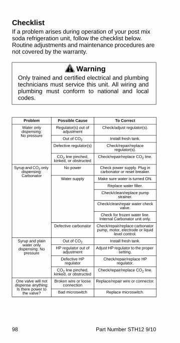
98 Part Number STH12 9/10
ChecklistIf a problem arises during operation of your post mix soda refrigeration unit, follow the checklist below. Routine adjustments and maintenance procedures are not covered by the warranty.
! WarningOnly trained and certified electrical and plumbingtechnicians must service this unit. All wiring andplumbing must conform to national and localcodes.
Problem Possible Cause To Correct
Water only dispensing:No pressure
Regulator(s) out of adjustment
Check/adjust regulator(s).
Out of CO2 Install fresh tank.
Defective regulator(s) Check/repair/replace regulator(s).
CO2 line pinched, kinked, or obstructed
Check/repair/replace CO2 line.
Syrup and CO2 only dispensing:Carbonator
No power Check power supply. Plug in carbonator or reset breaker.
Water supply Make sure water is turned ON.
Replace water filter.
Check/clean/replace pump strainer.
Check/clean/repair water check valve.
Check for frozen water line. Internal Carbonator unit only.
Defective carbonator Check/repair/replace carbonator pump, motor, electrode or liquid
level control.
Syrup and plain water only
dispensing: No pressure
Out of CO2 Install fresh tank.
HP regulator out of adjustment
Adjust HP regulator to the proper setting.
Defective HP regulator
Check/repair/replace HP regulator.
CO2 line pinched, kinked, or obstructed
Check/repair/replace CO2 line.
One valve will not dispense anything:Is there power to
the valve?
Broken wire or loose connection
Replace/repair wire or connector.
Bad microswitch Replace microswitch.

Part Number STH12 9/10 99
Beverage dispensed is too
sweet:Is the ratio (brix) of the drink correct?
Flow control out of adjustment
Adjust the flow control.
Insufficient soda flow due to low carbonator
pressure
Adjust CO2 pressure or change the tank.
Low CO2 pressure due to leaks
Repair CO2 leaks.
Obstruction in the water or soda line
Clean out the lines.
Beverage is not sweet enough:
Is the ratio (brix) of the drink correct?
Flow control out of adjustment
Adjust the flow control.
Soda flow too high Reset CO2 pressure or replace regulator if necessary.
Obstruction in syrup line
Clean out the syrup line.
Drinks are foaming:Are system
pressures correct?
Over carbonation Check CO2 supply. Reset pressure or replace regulator is
necessary.
Dirty lines/valves Clean/sanitize entire system.
Problem Possible Cause To Correct
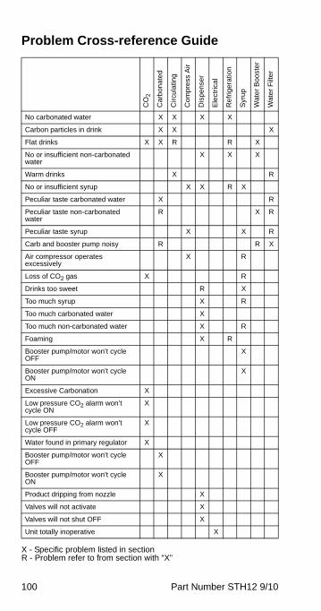
100 Part Number STH12 9/10
Problem Cross-reference Guide
X - Specific problem listed in section R - Problem refer to from section with “X”
CO
2
Ca
rbon
ate
d
Cir
cula
ting
Co
mp
ress
Air
Dis
pe
nse
r
Ele
ctri
cal
Re
frig
erat
ion
Syr
up
Wat
er
Bo
ost
er
Wat
er
Filt
er
No carbonated water X X X X
Carbon particles in drink X X X
Flat drinks X X R R X
No or insufficient non-carbonated water
X X X
Warm drinks X R
No or insufficient syrup X X R X
Peculiar taste carbonated water X R
Peculiar taste non-carbonated water
R X R
Peculiar taste syrup X X R
Carb and booster pump noisy R R X
Air compressor operates excessively
X R
Loss of CO2 gas X R
Drinks too sweet R X
Too much syrup X R
Too much carbonated water X
Too much non-carbonated water X R
Foaming X R
Booster pump/motor won’t cycle OFF
X
Booster pump/motor won’t cycle ON
X
Excessive Carbonation X
Low pressure CO2 alarm won’t cycle ON
X
Low pressure CO2 alarm won’t cycle OFF
X
Water found in primary regulator X
Booster pump/motor won’t cycle OFF
X
Booster pump/motor won’t cycle ON
X
Product dripping from nozzle X
Valves will not activate X
Valves will not shut OFF X
Unit totally inoperative X
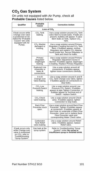
Part Number STH12 9/10 101
CO2 Gas SystemOn units not equipped with Air Pump, check all Probable Causes listed below.
Qualifier Probable Cause Corrective Action
Loss of CO2
If leak occurs while Change-over valve is positioned on Air, follow the “Probable Causes” (for units equipped with Air
Pump).
CO2 Tank leaking.
Use a soap solution around CO2 Tank valve Stem to locate leaks. If leaks are present, bubbles will appear. If valve
Stem leaks at Tank, replace CO2 Tank.
CO2 Washer damaged or
missing.
Use a soap solution around Primary Regulator Coupling Nut and CO2 Tank
Stem. If bubbles appear, remove Regulator and replace CO2 Washer
found inside Nut. Secure Regulator to Tank and check for leaks.
Primary Regulator
Diaphragm leaking.
Use a soap solution around Primary Regulator Adjustment Screw in
Bonnet. If bubbles appear, diaphragm is leading. Replace Primary Regulator.
Ruptured Line Assembly or
leaks at connections.
Use a soap solution around all connections. If bubbles appear,
tighten loose connections carefully.
A to B Change-over Valve leaking.
Use a soap solution around A and B CO2 Tank Change-over Valve, tighten if bubbles appear at Connections to
stop leaks.
CO2 Low Pressure Switch
leaking.
Use a soap solution around Low Pressure CO2 Switch. If bubbles
appear at pipe, tighten Connection. If bubbles appear at Terminal end of
Switch - replace Switch.
CO2 Check valve leaking.
Use a soap solution around Check valve. If bubbles appear, tighten
Connection to stop leaks.
Back Flow Preventer stuck
open.
Use a soap solution around Back Flow Preventer. Tighten if bubbles appear at connection. If bubbles appear at
Vent Hole on underside of Back Flow Preventer, clean out or replace Back
Flow Preventer valve and corresponding Water Check valve.
Carbonator Tank Relief
valve leaking.
Use a soap solution around Relief valve. If bubbles appear, replace
Relief valve.
If leak occurs only while Change-over valve is positioned
on CO2, refer to Troubleshooting “Syrup System”.
Gas leak at the syrup system.
Refer to Troubleshooting “Syrup System” under No syrup or
insufficient syrup in finished drink.

102 Part Number STH12 9/10
Flat drinks (lack of carbonation in carbonated water)
Primary Regulator (less than 500 psi
[34.5 bar]).
CO2 Supply exhausted (CO2
Tank is functionally
empty if pressure reads less than 500 psi [34.5 bar]).
Verify CO2 Tank pressure is a minimum of 500 psi (34.5 bar) on the Primary Pressure Regulator Gauge marked 0-2000 psi. Replace tank if
necessary.
Primary Regulator out of adjustment or inoperative.
Verify CO2 Primary Regulators are set at 90 psi (6.3 kg/cm2). Adjust if
necessary. If Regulator will not stay in adjustment, replace Regulator.
CO2 Supply adequate (greater
than 500 psi [34.5 bar]).
A and B CO2 Tank
Change-over Valve incorrectly
positioned.
If A and B CO2 Tank Change-over Valve is positioned on an empty Tank or halfway between A and B operating
positions, CO2 is not supplied to Carbonators. Ensure valve handler is
in the “operating” position.
Malfunction of the
Refrigeration System.
Refer to Troubleshooting “Refrigeration System” under Warm
drinks.
Water Filter restricted.
Refer to Troubleshooting “Water Filter System” under Peculiar taste.
Malfunction of the Carbonated Water System.
Refer to Troubleshooting “Carbonated Water System” under Flat drinks.
Excessive carbonation (foaming).
Primary Regulators set
too high.
Verify CO2 Primary Regulators are set at 90 psi (6.3 kg/cm2). Adjust if
necessary. If Regulator will not stay in adjustment, replace regulator.
Replace.
Low Pressure CO2 Warning light or buzzer does not
come ON.
Warning lamp or buzzer burned
out. Transformer inoperative.
When CO2 Tank is empty and CO2 warning lamp(s) or buzzer fail, verify
voltage across Transformer. If no voltage, replace Transformer.
Pressure Switch defective.
If CO2 Warning lamps or buzzer and transformer are operative. Pressure
Switch is defective and must be replaced.
Qualifier Probable Cause Corrective Action
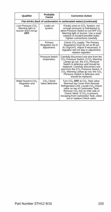
Part Number STH12 9/10 103
Flat drinks (lack of carbonation in carbonated water) (continued)
Low Pressure CO2 Warning light or
buzzer does not go OFF.
Leaks on system.
If leaks exist on CO2 System, not enough pressure is maintained to
allow Pressure Switch to cut OFF CO2 Warning light or buzzer. Use a soap solution to located possible leaks.
Tighten connections carefully.
Primary Regulator out of
adjustment.
Check CO2 supply. The Primary Regulators must be set at 90 psi
(6.3 kg/cm2). Adjust if necessary. If regulator will not stay in adjustment,
replace regulator.
Pressure Switch inoperative.
Carefully disconnect one wire from the CO2 Pressure Switch, if CO2 Warning
Lamps go out, the CO2 Pressure Switch is defective and should be replaced. Carefully disconnect one
wire from the CO2 Pressure Switch, if CO2 Warning Lamps go out, the CO2
Pressure Switch is defective and should be replaced.
Water found in CO2 Regulator and
lines.
CO2 Check Valve defective.
Turn CO2 OFF at CO2 Tank valve. Remove top Cover from Remote
Refrigeration Unit. Locate CO2 Check valve on top of Carbonator Tank. Remove CO2 line on Inlet side of Check Valve. If CO2 is present,
escaping from Carbonator Tank, clean out or replace Check valve.
Qualifier Probable Cause Corrective Action
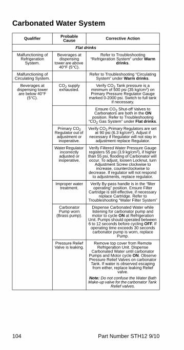
104 Part Number STH12 9/10
Carbonated Water System
Qualifier Probable Cause Corrective Action
Flat drinks
Malfunctioning of Refrigeration
System.
Beverages at dispensing
tower are above 40°F (5°C).
Refer to Troubleshooting “Refrigeration System” under Warm
drinks.
Malfunctioning of Circulating System.
Refer to Troubleshooting “Circulating System” under Warm drinks.
Beverages at dispensing tower are below 40°F
(5°C).
CO2 supply exhausted.
Verify CO2 Tank pressure is a minimum of 500 psi (35 kg/cm2) on Primary Pressure Regulator Gauge
marked 0-2000 psi. Switch to full tank if necessary.
Ensure CO2 Shut-off Valves to Carbonators are both in the ON
position. Refer to Troubleshooting “CO2 Gas System” under Flat drinks.
Primary CO2 Regulator out of adjustment or inoperative.
Verify CO2 Primary Regulators are set at 90 psi (6.3 kg/cm2). Adjust if
necessary if Regulator will not stay in adjustment replace Regulator.
Water Regulator incorrectly adjusted or inoperative.
Verify Filtered Water Pressure Gauge registers 55 psi (3.9 kg/cm2), if higher than 55 psi, flooding of Carbonator will occur. To adjust, loosen Locknut, turn
Adjustment Screw clockwise to increase, counterclockwise to
decrease. If regulator will not respond to adjustments, replace regulator.
Improper water treatment.
Verify By-pass handle is in the “filter operating” position. Ensure Filter
Cartridge is still effective, if necessary replace Cartridge. Refer to
Troubleshooting “Water Filter System”
Carbonator Pump worn
(Brass pump).
Dispense Carbonated Water while listening for carbonator pump and motor to cycle ON at Refrigeration
Unit. Pumps should operated between 6 to 12 seconds before cycling OFF. If operating time exceeds 30 seconds carbonator pump is worn, replace
Pump.
Pressure Relief Valve is leaking.
Remove top cover from Remote Refrigeration Unit. Dispense
Carbonated Water until carbonator Pumps and Motor cycle ON. Observe Pressure Relief Valves on carbonator Tank. If water is observed escaping from either, replace leaking Relief
valve.
Note: Do not confuse the Water Bath Make-up valve for the carbonator Tank
Relief valves.
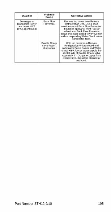
Part Number STH12 9/10 105
Beverages at Dispensing Tower
are below 40°F (5°C). (continued)
Back Flow Preventer.
Remove top cover from Remote Refrigeration Unit. Use a soap
solution around Back Flow Preventer. If bubbles appear at Vent Hole or
underside of Back Flow Preventer, clean or replace Back Flow Preventer and corresponding Water Check valve
carbonator Tank.
Double Check valve (water) stuck open.
With top cover from Remote Refrigeration Unit removed and
carbonator Pump Switch and Water turned OFF, loosen water supply line at inlet side of Double Check valve Assembly. If CO2 gas escapes from Check valve, it must be cleaned or
replaced.
Qualifier Probable Cause Corrective Action
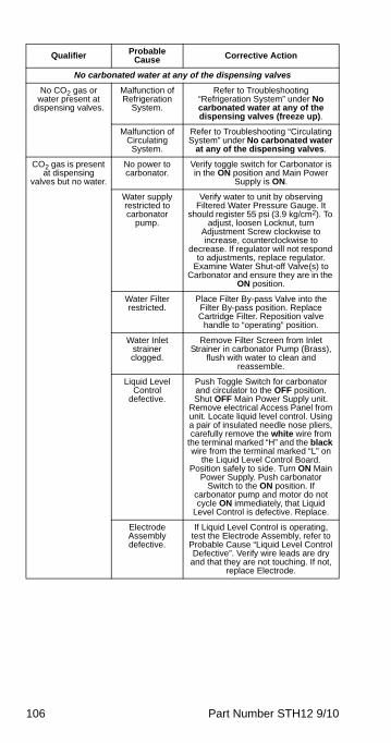
106 Part Number STH12 9/10
No carbonated water at any of the dispensing valves
No CO2 gas or water present at
dispensing valves.
Malfunction of Refrigeration
System.
Refer to Troubleshooting “Refrigeration System” under No carbonated water at any of the dispensing valves (freeze up).
Malfunction of Circulating System.
Refer to Troubleshooting “Circulating System” under No carbonated water
at any of the dispensing valves.
CO2 gas is present at dispensing
valves but no water.
No power to carbonator.
Verify toggle switch for Carbonator is in the ON position and Main Power
Supply is ON.
Water supply restricted to carbonator
pump.
Verify water to unit by observing Filtered Water Pressure Gauge. It
should register 55 psi (3.9 kg/cm2). To adjust, loosen Locknut, turn
Adjustment Screw clockwise to increase, counterclockwise to
decrease. If regulator will not respond to adjustments, replace regulator.
Examine Water Shut-off Valve(s) to Carbonator and ensure they are in the
ON position.
Water Filter restricted.
Place Filter By-pass Valve into the Filter By-pass position. Replace Cartridge Filter. Reposition valve
handle to “operating” position.
Water Inlet strainer clogged.
Remove Filter Screen from Inlet Strainer in carbonator Pump (Brass),
flush with water to clean and reassemble.
Liquid Level Control
defective.
Push Toggle Switch for carbonator and circulator to the OFF position. Shut OFF Main Power Supply unit.
Remove electrical Access Panel from unit. Locate liquid level control. Using a pair of insulated needle nose pliers, carefully remove the white wire from
the terminal marked “H” and the black wire from the terminal marked “L” on
the Liquid Level Control Board. Position safely to side. Turn ON Main
Power Supply. Push carbonator Switch to the ON position. If
carbonator pump and motor do not cycle ON immediately, that Liquid
Level Control is defective. Replace.
Electrode Assembly defective.
If Liquid Level Control is operating, test the Electrode Assembly, refer to
Probable Cause “Liquid Level Control Defective”. Verify wire leads are dry
and that they are not touching. If not, replace Electrode.
Qualifier Probable Cause Corrective Action
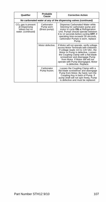
Part Number STH12 9/10 107
No carbonated water at any of the dispensing valves (continued)
CO2 gas is present at Dispensing Valves but no
water. (continued)
Carbonator Pump worn
(Brass pump).
Dispense Carbonated Water while listening for carbonator pump and motor to cycle ON at Refrigeration
Unit. Pumps should operate between 6 to 12 seconds before cycling OFF. If operating time exceeds 30 seconds, carbonator Pumps is worn, replace
Pump.
Motor defective. If Motor will not operate, verify voltage across Motor Terminals with voltmeter. If voltage reads 110 to 120 VAC, the Motor or Pump is defective. Loosen the Coupling Clamp with a flat-blade
screwdriver and disengage Pump from Motor. If Motor still will not
operate with Pump disengaged, Motor is defective. Replace.
Carbonator Pump frozen.
Loosen the Coupling Clamp with a flat-blade screwdriver and disengage Pump from Motor. By hand, turn the
Coupling Key in back of Pump. If pump shaft will not spin freely, Pump is defective and must be replaced.
Qualifier Probable Cause Corrective Action
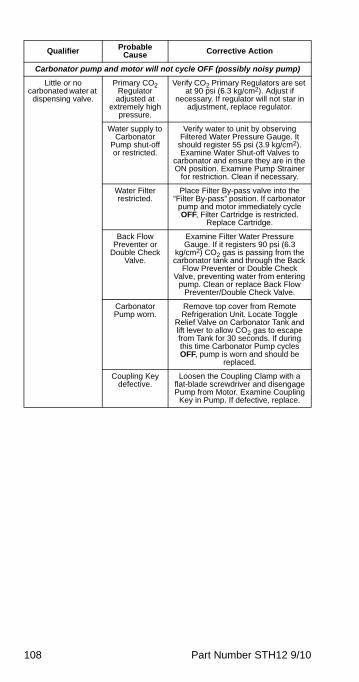
108 Part Number STH12 9/10
Carbonator pump and motor will not cycle OFF (possibly noisy pump)
Little or no carbonated water at
dispensing valve.
Primary CO2 Regulator
adjusted at extremely high
pressure.
Verify CO2 Primary Regulators are set at 90 psi (6.3 kg/cm2). Adjust if
necessary. If regulator will not star in adjustment, replace regulator.
Water supply to Carbonator
Pump shut-off or restricted.
Verify water to unit by observing Filtered Water Pressure Gauge. It
should register 55 psi (3.9 kg/cm2). Examine Water Shut-off Valves to
carbonator and ensure they are in the ON position. Examine Pump Strainer
for restriction. Clean if necessary.
Water Filter restricted.
Place Filter By-pass valve into the “Filter By-pass” position. If carbonator
pump and motor immediately cycle OFF, Filter Cartridge is restricted.
Replace Cartridge.
Back Flow Preventer or
Double Check Valve.
Examine Filter Water Pressure Gauge. If it registers 90 psi (6.3
kg/cm2) CO2 gas is passing from the carbonator tank and through the Back
Flow Preventer or Double Check Valve, preventing water from entering
pump. Clean or replace Back Flow Preventer/Double Check Valve.
Carbonator Pump worn.
Remove top cover from Remote Refrigeration Unit. Locate Toggle
Relief Valve on Carbonator Tank and lift lever to allow CO2 gas to escape from Tank for 30 seconds. If during this time Carbonator Pump cycles OFF, pump is worn and should be
replaced.
Coupling Key defective.
Loosen the Coupling Clamp with a flat-blade screwdriver and disengage Pump from Motor. Examine Coupling
Key in Pump. If defective, replace.
Qualifier Probable Cause Corrective Action
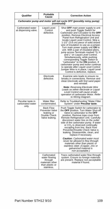
Part Number STH12 9/10 109
Carbonator pump and motor will not cycle OFF (possibly noisy pump) (continued)
Carbonated water at dispensing valve.
Liquid Level Control
defective.
Shut OFF main power supply to unit and push Toggle Switch for
Carbonator and Circulator to the OFF position. Remove Electrical Access Panel from Refrigeration Unit and locate Liquid Level Control. Strip a
1-1/2" (3.8 cm) piece of solid strand wire of insulation to use as a jumper. Turn main power supply unit ON to unit. With a pair of insulated pliers,
jump across Terminals marked “G, H and L” on Liquid Level Control. Simultaneously, while pushing
corresponding Toggle Switch to “carbonator” to the ON position. If
carbonator pump and motor continue to operate after Liquid Level Control Jumper Wire is in place, Liquid Level
Control is defective, replace.
Electrode defective.
Examine wire leads to ensure no breaks in connections. Remove and clean Electrode with find sand paper
and reinstall.
Note: Reversing Electrode Wire Leads on either electrode or Liquid
Level Control will cause erratic operation of carbonator Motor. Refer
to Wiring Diagram.
Peculiar taste in carbonated water
only.
Water filter contaminated.
Refer to Troubleshooting “Water Filter System” under Peculiar taste.
Back Flow Preventer Valve
leaking or Double Check Valve leaking.
Push Toggle Switch for carbonator to the OFF position. Turn Water Shut-off
Valve to carbonator to the OFF position. Remove tope cover from
Remote Refrigeration Unit. Carefully disconnect water line on the outlet
side of the carbonator pump. If water or CO2 is observed continually escaping from line, Back Flow
Preventer/Double Check Valve is leaking. Disassemble, clean, and
replace if necessary.
Caution: Carbonated water must never be allowed to flow through
materials other than plastic or stainless steel. (Copper, zinc or
galvanized material is non-acceptable.)
Carbonated water flowing
through materials other than plastic or
stainless.
Trace carbonated water flow through system. Ensure no foreign materials are present. Replace non-acceptable
material if found.
Qualifier Probable Cause Corrective Action
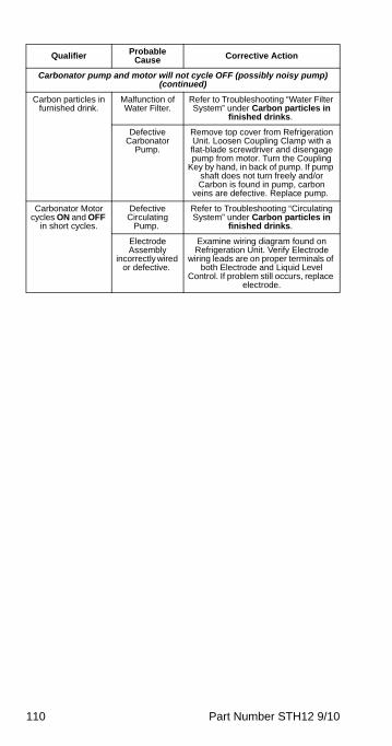
110 Part Number STH12 9/10
Carbonator pump and motor will not cycle OFF (possibly noisy pump) (continued)
Carbon particles in furnished drink.
Malfunction of Water Filter.
Refer to Troubleshooting “Water Filter System” under Carbon particles in
finished drinks.
Defective Carbonator
Pump.
Remove top cover from Refrigeration Unit. Loosen Coupling Clamp with a flat-blade screwdriver and disengage pump from motor. Turn the Coupling
Key by hand, in back of pump. If pump shaft does not turn freely and/or Carbon is found in pump, carbon
veins are defective. Replace pump.
Carbonator Motor cycles ON and OFF
in short cycles.
Defective Circulating
Pump.
Refer to Troubleshooting “Circulating System” under Carbon particles in
finished drinks.
Electrode Assembly
incorrectly wired or defective.
Examine wiring diagram found on Refrigeration Unit. Verify Electrode
wiring leads are on proper terminals of both Electrode and Liquid Level
Control. If problem still occurs, replace electrode.
Qualifier Probable Cause Corrective Action
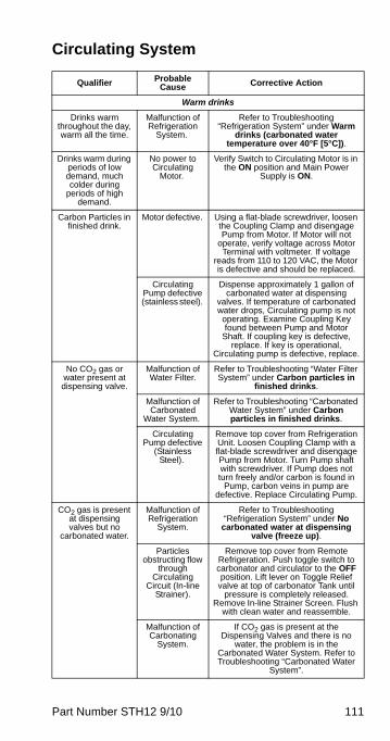
Part Number STH12 9/10 111
Circulating System
Qualifier Probable Cause Corrective Action
Warm drinks
Drinks warm throughout the day, warm all the time.
Malfunction of Refrigeration
System.
Refer to Troubleshooting “Refrigeration System” under Warm
drinks (carbonated water temperature over 40°F [5°C]).
Drinks warm during periods of low demand, much colder during
periods of high demand.
No power to Circulating
Motor.
Verify Switch to Circulating Motor is in the ON position and Main Power
Supply is ON.
Carbon Particles in finished drink.
Motor defective. Using a flat-blade screwdriver, loosen the Coupling Clamp and disengage Pump from Motor. If Motor will not
operate, verify voltage across Motor Terminal with voltmeter. If voltage
reads from 110 to 120 VAC, the Motor is defective and should be replaced.
Circulating Pump defective (stainless steel).
Dispense approximately 1 gallon of carbonated water at dispensing
valves. If temperature of carbonated water drops, Circulating pump is not operating. Examine Coupling Key found between Pump and Motor
Shaft. If coupling key is defective, replace. If key is operational,
Circulating pump is defective, replace.
No CO2 gas or water present at dispensing valve.
Malfunction of Water Filter.
Refer to Troubleshooting “Water Filter System” under Carbon particles in
finished drinks.
Malfunction of Carbonated
Water System.
Refer to Troubleshooting “Carbonated Water System” under Carbon particles in finished drinks.
Circulating Pump defective
(Stainless Steel).
Remove top cover from Refrigeration Unit. Loosen Coupling Clamp with a flat-blade screwdriver and disengage Pump from Motor. Turn Pump shaft with screwdriver. If Pump does not turn freely and/or carbon is found in
Pump, carbon veins in pump are defective. Replace Circulating Pump.
CO2 gas is present at dispensing valves but no
carbonated water.
Malfunction of Refrigeration
System.
Refer to Troubleshooting “Refrigeration System” under No
carbonated water at dispensing valve (freeze up).
Particles obstructing flow
through Circulating
Circuit (In-line Strainer).
Remove top cover from Remote Refrigeration. Push toggle switch to carbonator and circulator to the OFF position. Lift lever on Toggle Relief
valve at top of carbonator Tank until pressure is completely released.
Remove In-line Strainer Screen. Flush with clean water and reassemble.
Malfunction of Carbonating
System.
If CO2 gas is present at the Dispensing Valves and there is no
water, the problem is in the Carbonated Water System. Refer to Troubleshooting “Carbonated Water
System”.
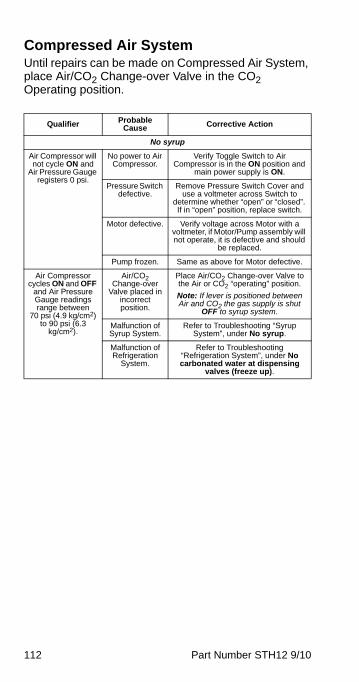
112 Part Number STH12 9/10
Compressed Air SystemUntil repairs can be made on Compressed Air System, place Air/CO2 Change-over Valve in the CO2 Operating position.
Qualifier Probable Cause Corrective Action
No syrup
Air Compressor will not cycle ON and
Air Pressure Gauge registers 0 psi.
No power to Air Compressor.
Verify Toggle Switch to Air Compressor is in the ON position and
main power supply is ON.
Pressure Switch defective.
Remove Pressure Switch Cover and use a voltmeter across Switch to
determine whether “open” or “closed”. If in “open” position, replace switch.
Motor defective. Verify voltage across Motor with a voltmeter, if Motor/Pump assembly will not operate, it is defective and should
be replaced.
Pump frozen. Same as above for Motor defective.
Air Compressor cycles ON and OFF
and Air Pressure Gauge readings range between
70 psi (4.9 kg/cm2) to 90 psi (6.3
kg/cm2).
Air/CO2 Change-over
Valve placed in incorrect position.
Place Air/CO2 Change-over Valve to the Air or CO2 “operating” position.
Note: If lever is positioned between Air and CO2 the gas supply is shut
OFF to syrup system.
Malfunction of Syrup System.
Refer to Troubleshooting “Syrup System”, under No syrup.
Malfunction of Refrigeration
System.
Refer to Troubleshooting “Refrigeration System”, under No carbonated water at dispensing
valves (freeze up).
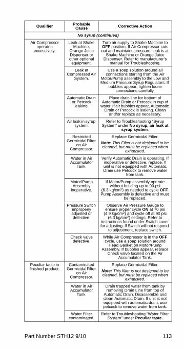
Part Number STH12 9/10 113
No syrup (continued)
Air Compressor operates
excessively.
Leak at Shake Machine,
Orange Juice Dispenser or other optional
equipment.
Turn air supply to Shake Machine to OFF position. If Air Compressor cuts out and maintains pressure, leak is at
Shake Machine or Orange Juice Dispenser. Refer to manufacturer’s
manual for Troubleshooting.
Leak at Compressed Air
System.
Use a soap solution around all connections starting from the Air
Motor/Pump assembly to the Low and Medium Pressure Syrup Regulators. If
bubbles appear, tighten loose connections carefully.
Automatic Drain or Petcock
leaking.
Place drain line for bottom of Automatic Drain or Petcock in cup of
water. If air bubbles appear, Automatic Drain or Petcock is leaking. Clean
and/or replace as necessary.
Air leak in syrup system.
Refer to Troubleshooting “Syrup System” under No syrup, air leak at
syrup system.
Restricted Germicidal Filter
on Air Compressor.
Replace Germicidal Filter.
Note: This Filter is not designed to be cleaned, but must be replaced when
exhausted.
Water in Air Accumulator
Tank.
Verify Automatic Drain is operating. If inoperative or defective, replace. If unit is not equipped with Automatic Drain use Petcock to remove water
from tank.
Motor/Pump Assembly
inoperative.
If Motor/Pump assembly operate without building up to 90 psi
(6.3 kg/cm2) as needed to cycle OFF. Pump Assembly is defective and must
be replaced.
Pressure Switch improperly adjusted or defective.
Observe Air Pressure Gauge to ensure proper cycle ON at 70 psi
(4.9 kg/cm2) and cycle off at 90 psi (6.3 kg/cm2) settings. Refer to
instructions found under Switch cover for adjusting. If Switch will not respond
to adjustment, replace switch.
Check valve defective.
While Air Compressor is in the OFF cycle, use a soap solution around
Head Gasket on Motor/Pump Assembly. If bubbles appear, replace
Check valve located on the Air Accumulator Tank.
Peculiar taste in finished product.
Contaminated Germicidal Filter
on Air Compressor.
Replace Germicidal Filter.
Note: This filter is not designed to be cleaned, but must be replaced when
exhausted.
Water in Air Accumulator
Tank.
Drain trapped water from tank by removing Drain Line from top of
Automatic Drain. Disassemble and clean Automatic Drain. If unit is not equipped with automatic drain, use petcock to remove water from tank.
Water Filter contaminated.
Refer to Troubleshooting “Water Filter System” under Peculiar taste.
Qualifier Probable Cause Corrective Action
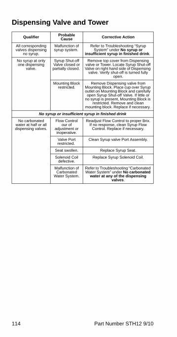
114 Part Number STH12 9/10
Dispensing Valve and Tower
Qualifier Probable Cause Corrective Action
All corresponding valves dispensing
no syrup.
Malfunction of syrup system.
Refer to Troubleshooting “Syrup System” under No syrup or
insufficient syrup in finished drink.
No syrup at only one dispensing
valve.
Syrup Shut-off Valve closed or partially closed.
Remove top cover from Dispensing valve or Tower. Locate Syrup Shut-off Valve on right hand side of Dispensing
valve. Verify shut-off is turned fully open.
Mounting Block restricted.
Remove Dispensing valve from Mounting Block. Place cup over Syrup outlet on Mounting Block and carefully open Syrup Shut-off Valve. If little or
no syrup is present, Mounting Block is restricted. Remove and clean
mounting block. Replace if necessary.
No syrup or insufficient syrup in finished drink
No carbonated water at half or all dispensing valves.
Flow Control our of
adjustment or inoperative.
Readjust Flow Control to proper Brix. If no response, clean Syrup Flow
Control. Replace if necessary.
Valve Port restricted.
Clean Syrup valve Port Assembly.
Seat swollen. Replace Syrup Seat.
Solenoid Coil defective.
Replace Syrup Solenoid Coil.
Malfunction of Carbonated
Water System.
Refer to Troubleshooting “Carbonated Water System” under No carbonated
water at any of the dispensing valves.
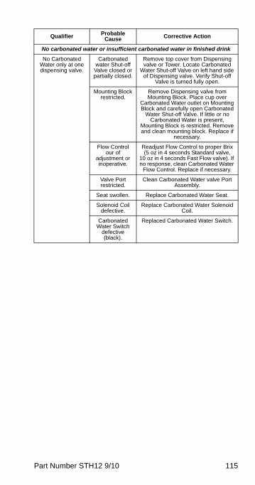
Part Number STH12 9/10 115
No carbonated water or insufficient carbonated water in finished drink
No Carbonated Water only at one dispensing valve.
Carbonated water Shut-off
Valve closed or partially closed.
Remove top cover from Dispensing valve or Tower. Locate Carbonated
Water Shut-off Valve on left hand side of Dispensing valve. Verify Shut-off
Valve is turned fully open.
Mounting Block restricted.
Remove Dispensing valve from Mounting Block. Place cup over
Carbonated Water outlet on Mounting Block and carefully open Carbonated
Water Shut-off Valve. If little or no Carbonated Water is present,
Mounting Block is restricted. Remove and clean mounting block. Replace if
necessary.
Flow Control our of
adjustment or inoperative.
Readjust Flow Control to proper Brix (5 oz in 4 seconds Standard valve,
10 oz in 4 seconds Fast Flow valve). If no response, clean Carbonated Water
Flow Control. Replace if necessary.
Valve Port restricted.
Clean Carbonated Water valve Port Assembly.
Seat swollen. Replace Carbonated Water Seat.
Solenoid Coil defective.
Replace Carbonated Water Solenoid Coil.
Carbonated Water Switch
defective (black).
Replaced Carbonated Water Switch.
Qualifier Probable Cause Corrective Action
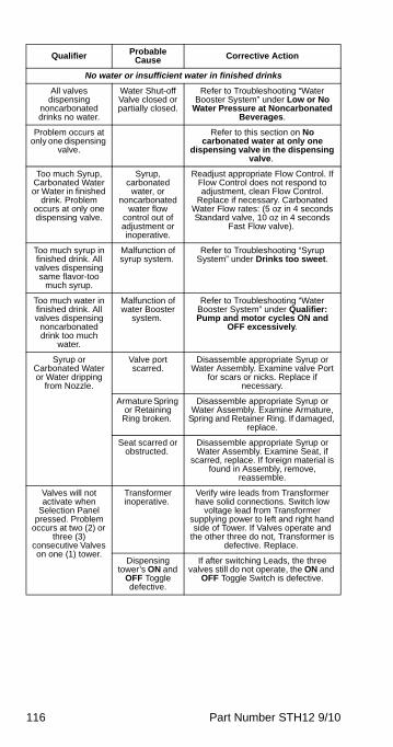
116 Part Number STH12 9/10
No water or insufficient water in finished drinks
All valves dispensing
noncarbonated drinks no water.
Water Shut-off Valve closed or partially closed.
Refer to Troubleshooting “Water Booster System” under Low or No
Water Pressure at Noncarbonated Beverages.
Problem occurs at only one dispensing
valve.
Refer to this section on No carbonated water at only one
dispensing valve in the dispensing valve.
Too much Syrup, Carbonated Water or Water in finished
drink. Problem occurs at only one dispensing valve.
Syrup, carbonated
water, or noncarbonated
water flow control out of adjustment or inoperative.
Readjust appropriate Flow Control. If Flow Control does not respond to adjustment, clean Flow Control.
Replace if necessary. Carbonated Water Flow rates: (5 oz in 4 seconds Standard valve, 10 oz in 4 seconds
Fast Flow valve).
Too much syrup in finished drink. All valves dispensing same flavor-too
much syrup.
Malfunction of syrup system.
Refer to Troubleshooting “Syrup System” under Drinks too sweet.
Too much water in finished drink. All valves dispensing
noncarbonated drink too much
water.
Malfunction of water Booster
system.
Refer to Troubleshooting “Water Booster System” under Qualifier: Pump and motor cycles ON and
OFF excessively.
Syrup or Carbonated Water or Water dripping
from Nozzle.
Valve port scarred.
Disassemble appropriate Syrup or Water Assembly. Examine valve Port
for scars or nicks. Replace if necessary.
Armature Spring or Retaining
Ring broken.
Disassemble appropriate Syrup or Water Assembly. Examine Armature,
Spring and Retainer Ring. If damaged, replace.
Seat scarred or obstructed.
Disassemble appropriate Syrup or Water Assembly. Examine Seat, if
scarred, replace. If foreign material is found in Assembly, remove,
reassemble.
Valves will not activate when
Selection Panel pressed. Problem
occurs at two (2) or three (3)
consecutive Valves on one (1) tower.
Transformer inoperative.
Verify wire leads from Transformer have solid connections. Switch low
voltage lead from Transformer supplying power to left and right hand side of Tower. If Valves operate and
the other three do not, Transformer is defective. Replace.
Dispensing tower’s ON and
OFF Toggle defective.
If after switching Leads, the three valves still do not operate, the ON and
OFF Toggle Switch is defective.
Qualifier Probable Cause Corrective Action
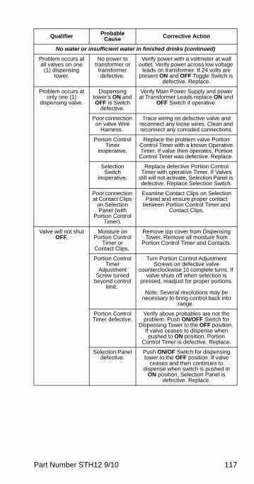
Part Number STH12 9/10 117
No water or insufficient water in finished drinks (continued)
Problem occurs at all valves on one
(1) dispensing tower.
No power to transformer or
transformer defective.
Verify power with a voltmeter at wall outlet. Verify power across low voltage
leads on transformer. If 24 volts are present ON and OFF Toggle Switch is
defective. Replace.
Problem occurs at only one (1)
dispensing valve.
Dispensing tower’s ON and OFF is Switch
defective.
Verify Main Power Supply and power at Transformer Leads replace ON and
OFF Switch if operative.
Poor connection on valve Wire
Harness.
Trace wiring on defective valve and reconnect any loose wires. Clean and reconnect any corroded connections.
Portion Control Timer
inoperative.
Replace the problem valve Portion Control Timer with a known Operative Timer. If valve then operates, Portion Control Timer was defective. Replace.
Selection Switch
inoperative.
Replace defective Portion Control Timer with operative Timer. If Valves
still will not activate, Selection Panel is defective. Replace Selection Switch.
Poor connection at Contact Clips
on Selection Panel (with
Portion Control Timer).
Examine Contact Clips on Selection Panel and ensure proper contact
between Portion Control Timer and Contact Clips.
Valve will not shut OFF.
Moisture on Portion Control
Timer or Contact Clips.
Remove top cover from Dispensing Tower. Remove all moisture from
Portion Control Timer and Contacts.
Portion Control Timer
Adjustment Screw turned
beyond control limit.
Turn Portion Control Adjustment Screws on defective valve
counterclockwise 10 complete turns. If valve shuts off when selection is
pressed, readjust for proper portions.
Note: Several revolutions may be necessary to bring control back into
range.
Portion Control Timer defective.
Verify above probables are not the problem. Push ON/OFF Switch for
Dispensing Tower to the OFF position. If valve ceases to dispense when pushed to ON position, Portion
Control Timer is defective. Replace.
Selection Panel defective.
Push ON/OF Switch for dispensing tower to the OFF position. If valve
ceases and then continues to dispense when switch is pushed in
ON position, Selection Panel is defective. Replace.
Qualifier Probable Cause Corrective Action
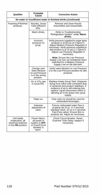
118 Part Number STH12 9/10
No water or insufficient water in finished drinks (continued)
Foaming of finished products.
Nozzles, Syrup Tube Diffusers
dirty.
Remove and clean Nozzle Assemblies and reassemble.
Warm drinks. Refer to Troubleshooting “Refrigeration System” under Warm
drinks.
Incorrect pressure on
syrup.
Verify pressure supplied to sugar base products is at 60 psi (4.2 kg/cm2).
Adjust Medium Pressure Regulator if necessary. Verify pressure supplied to diet product is at 15 psi (1.1 kg/cm2).
Adjust Low Pressure Regulator if necessary.
Note: Ensure the Low Pressure Supply Line has not mistakenly been
switched for a Medium Pressure Supply Line on the diet tank.
Change-over Valve Medium
or Low Pressure is in the wrong
position.
Verify valve Medium to Low Pressure is in the Low Pressure position for diet
products.
Air or CO2 gas in syrup line.
Replace empty Syrup Tank. Dispense Syrup from valve until consistent flow is achieved and product stabilizes. If evidence of air is still entering line, replace Liquid Disconnect which is allowing air to be drawn into syrup
supply.
Flake ice. Only cube ice should be used for carbonated beverages.
Improper adjustment of
valve.
Ensure carbonated water flow is properly set (5 oz. in 4 seconds
standard valve, 10 oz in 4 seconds Fast Flow valve). Ensure Brix is
properly set. Adjust as necessary.
Unit totally inoperative; all
electrical switches in the ON position.
Power failure, all power to
system is OFF, or Fuse/Circuit
Breaker is “open”.
Check Circuit Breaker. Reset. Examine Time Delay, replace if
necessary.
Qualifier Probable Cause Corrective Action

Part Number STH12 9/10 119
Electrical System
Qualifier Probable Cause Corrective Action
Fuse/Circuit Breaker is
open.
Short Circuit or overload within
unit.
Push Toggle Switches labeled carbonator and circulator to the OFF position. Push the
Toggle Switches for Booster Pump, Air Compressor, Agitator and Refrigeration to
the OFF position. Replace fuse(s) and reset circuit breaker. Push the Toggle
Switches ON in the following sequence as labeled below, to locate short or overload within unit, waiting momentarily between
steps. *Agitator *Refrigeration *Carbonator A and/or B *Circulator A and/or B (after carbonator Motor Cycles OFF) *Booster
Pump *Air Compressor.
Push the Agitator Toggle Switch in the ON position. If the fuse/circuit breaker opens, the trouble is in the Agitator Motor Circuit. This Circuit must be checked for shorts
and/or overload. If the fuse/circuit breaker does not open after running about 1
minute, the problem is not in the Agitator Motor Circuit.
Push the Refrigeration Toggle Switch in the ON position. If the fuses/circuit breaker opens, the trouble is in the Refrigeration
Circuit. Refer to wiring diagram for possible faulty components. Push the carbonator
Toggle Switch A to the ON position. Draw Carbonated Water from the Dispensing
valve until Pump cycles. If the fuse/circuit breaker opens, the trouble is in the
carbonator Circuit. Refer to wiring diagram for possible faulty components.
Push the carbonator Toggle Switch B to the ON position. Follow procedure above for carbonator A. Push the Circulator Toggle Switch A to the ON position. If fuse/circuit
breaker opens, the trouble is in the Circulator Circuit. Refer to wiring diagram for possible faulty components. Push the
Circulator Toggle Switch B to the ON position. Follow procedure above for
Circulator A.
Push the Booster Pump Toggle Switch to the ON position (allow unit to cycle). If
fuse/circuit breaker opens, the trouble is in the Booster Pump Circuit. Refer to wiring diagram for possible faulty components.
Push the Air Compressor Toggle Switch to the ON position. (Allow unit to cycle). If
fuse/circuit breaker opens, the trouble is in the Air Compressor Circuit. Refer to wiring diagram for possible faulty components.
Important Note: Worn out Circuit Breakers or low voltage are frequently responsible for shorts and overloads. Contact service
agent to examine possible defective Circuit Breakers or low voltage.
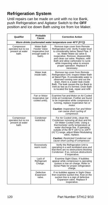
120 Part Number STH12 9/10
Refrigeration SystemUntil repairs can be made on unit with no Ice Bank, push Refrigeration and Agitator Switch to the OFF position and ice down Bath using ice from Ice Maker.
Qualifier Probable Cause Corrective Action
Warm drinks (carbonated water temperature over 40°F [5°C])
Compressor operates but no ice
present at water bath.
Water Bath Feeder Valve
inoperative (not enough water in
bath).
Remove tope cover from Remote Refrigeration Unit. Verify if water level is considerably below Stand Pipe. If
so, Water Make-Up valve is inoperative. Remove, disassemble and clean out valve. Replace, refill Bath and allow carbonator to cycle
while inspecting valve to ensure proper operation. Replace if
necessary.
Water leak inside bath.
Remove top cover from Remote Refrigeration Unit. Inspect Water Bath at Stand Pipe. If considerable water is
observed running over and out the drain, there is a water leak inside
Bath. The leak causes the Ice Bank to melt as fast as it’s formed. Drain Bath
to located the leak, repair and refill bath.
Fan or Motor inoperative (air cooled units).
Examine Fan and Motor on Air Cooled Units at Condenser. If either are found to be inoperative while compressor is
running, replace inoperative fan or motor.
Caution: Inoperative Fan and Motor can cause short cycling of
compressor.
Compressor operates but no ice
present at water bath.
Condenser restricted.
For Air Cooled Units, clean the Condenser removing all dust and lint.
On Water Cooled Units: Using a thermometer verify temperature at water discharge line. If operating
outside of the 95°F (35°C) to 105°F (41°C) range, adjust Water Modulating
valve, replace.
Caution: Restricted Condenser can cause short cycling of compressor.
Excessively warm room.
Verify the Refrigeration Unit is operating in a well ventilated area and that there are no obstructions blocking Condenser. If so, remove obstructions
if inoperative.
Lack of Refrigerant Charge.
Examine Sight Glass. If bubbles appear while compressor is operating
system is low on charge. Refer to Serial Plate for proper refrigeration
charge.
Defective Expansion
valve.
If no bubbles appear in Sight Glass then examine suction line, frost on the
suction line is a sign of defective Expansion valve. Replace if
inoperative.

Part Number STH12 9/10 121
Warm drinks (carbonated water temperature over 40°F [5°C]) (continued)
Compressor operates with Ice present at water
bath.
Defective Agitator Motor
Assembly.
Remove top cover from Remote Refrigeration Unit. Examine the Agitator Motor Assembly, ensure
propeller is secured to Agitator and that the Agitator Switch is in the ON
position, allowing the water in Bath to be agitated across the cooling coils. If
Motor or Propeller is inoperative, replace.
Malfunctioning of Circulating
System.
If ice is present on Evaporator Coil and Agitator Motor Assembly is
operating the Refrigeration System is functioning. However, the Circulating System may not be functioning. Refer
to Troubleshooting “Circulating System”.
Caution: Always make certain that proper line voltage is present.
Compressor won’t operate and no ice
at water bath.
Defective Switch.
Check to ensure Refrigeration Switch is in the ON position.
Fuse/Circuit Breaker open.
Locate Circuit Breaker box and identify proper breaker for Remote
Refrigeration Unit. Ensure it is in the ON position by switching OFF and then ON again. If breaker will not
reset, refer to Troubleshooting “Electrical System”.
Time Delay Fuse burned
out.
Inspect Time Delay Fuses at the wall quick shut-off panel. One of the fuses may be burned out causing half the
unit to shut down. If this is suspected replace all of the fuses.
Defective High Pressure Control.
Examine High Pressure Control to ensure wire leads are securely
attached to terminals. If trouble is suspected with control, replace.
Defective Ice Bank Control.
Remove Electrical Access Panel and using a voltmeter across the Ice Bank Control, verify control is in the “closed” position. If control is found to be in the “open” position, that Control should be
replaced.
Defective Contactor.
Remove Electrical Access Panel. Use a voltmeter across Contactor Coil. If
current exists across Coil, and Contactor remains “open”, Contactor
is defective. Replace.
Defective Relay or Defective Capacitor or
Defective Overload.
Examine Relay/Capacitor/Overload to ensure wire leads are securely
attached to terminals. Replace any faulty components.
Defective compressor.
If after checking each of the above items, you still experience problems, test compressor for possible defects
or grounding.
Qualifier Probable Cause Corrective Action

122 Part Number STH12 9/10
No carbonated water at any of the dispensing valves
CO2 gas is present at dispensing valves but no
Carbonated Water.
Malfunctioning of Carbonating
System.
If CO2 gas is present at the Dispensing Valves and there is no
water, the problem is in the Carbonated Water System. Refer to Troubleshooting “Carbonated Water
System”.
No CO2 Gas or water present at dispensing valve.
In a “freeze up” situation, push Refrigeration and Agitator Toggle
Switches to the OFF position. Drain water from Bath. Pour lukewarm
(never hot) water over the Product Coils until thawed. Ice down Water Bath using ice from Ice Maker until
further repairs can be made.
Defective Agitator.
Examine the Agitator Motor Assembly. Ensure Propeller is operating and secured to Agitator and that the
Agitator Toggle Switch is in the ON position. If Motor is inoperative,
replace.
Defective Ice Bank Control.
Remove Electrical Access Panel. Use a voltmeter across the Ice Bank
Control. Verify Control is in the “open” position. If Control is stuck in the
“closed” position, the unit will “freeze up”. Replace Control if necessary. If
unit builds and Ice Bank to the point of extending into stainless steel coils, the
Ice Bank Control must be replaced.
On units equipped with the “Red” Refrigeration
Warning Light.
Defective Contactor.
Use a voltmeter across Contactor Coil. If no current is present across
Coil, but Contactor remains “closed”, Contactor is defective. Replace
defective Contactor.
Defective Primary Ice
Bank Control.
When the Refrigeration Warning Light illuminates, the Primary Ice Bank Control is defective and should be replaced. The Secondary Control operates the Compressor until the
Primary Control is replaced.
Refrigeration Warning Light
cycles ON and OFF with Compressor.
Note: When the Refrigeration Compressor cycles ON, Warning Light will turn OFF. When the Compressor cycles OFF the light will illuminate.
Qualifier Probable Cause Corrective Action

Part Number STH12 9/10 123
Syrup System
Qualifier Probable Cause Corrective Action
No syrup or insufficient syrup in
finished drink.
Syrup Tank is empty.
Replace Syrup tank and purge air out of Dispensing Valves affected, until steady syrup supply is dispensed.
Kinked Syrup lines.
Examine all exposed Syrup Lines and relieve any sharp bends or kinks.
Note: Observe all independent lines from Syrup Tank to Filters for kinks or
bends. Correct as needed.
Low Pressure Regulator
inoperative.
Low Pressure Regulator controls the pressure to diet beverages. Verify
pressure is set at 15 psi (1.1 kg/cm2). To increase, adjust clockwise, to
decrease, adjust counterclockwise. If regulator does not respond, repair or
replace regulator.
Medium Pressure Regulator
inoperative.
Medium Regulator controls the pressure applied to the sugar based
beverages. Verify pressure is set at 60 psi (4.2 kg/cm2). To increase, adjust
clockwise. To decrease, adjust counterclockwise. If regulator does
not respond, repair or replace regulator.
Check Relief valve restricted.
Disengage Gas Quick Disconnect on suspected restricted flavor at Syrup
Tank. Depress Poppet valve on bottom side of Gas Disconnect. If a
low or poor pressure supply is apparent, replace Check Relief valve.
Gas/Syrup Tank Plug Valves inoperative.
Replace Syrup Tank. If this solves the problem, tag defective tank so bottler
can make necessary repairs. (It is extremely rare to have inoperative
Tank Plug Valves.)
Quick Disconnects
(Gas or Syrup) not fully
engaged on Syrup Tank.
Disengage Quick Disconnects on one Tank at a time. Rinse and clean with warm water. Lubricate the O-ring on
the Syrup Tank Plug with water. Reattach the Quick Disconnects to the
appropriate Syrup Tank Plug. Gas Quick Disconnects are gray or have
two key slots. Syrup Quick Disconnects are black or have three
key slots.
Quick Disconnect
Valves or Tank Jumper
inoperative.
Gas Quick Disconnects: Open the Relief valve on the top of the syrup
tank lid. If the Gas Quick Disconnect is opening properly, pressure should
continue to bleed from the Gas Relief valve. If not, replace Gas Quick
Disconnect. Syrup Quick Disconnects: Open the Dispensing valve (Syrup Side only) for appropriate flavor. Dispensing syrup for at least 10
seconds. If CO2/Air pockets appear in syrup, replace Syrup Quick
Disconnect. If syrup flow is inadequate or fluctuates during 10 seconds of
flow, replace Syrup Quick Disconnects.
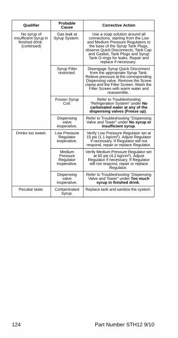
124 Part Number STH12 9/10
No syrup of insufficient Syrup in
finished drink. (continued)
Gas leak at Syrup System.
Use a soap solution around all connections, starting from the Low
and Medium Pressure Regulators to the base of the Syrup Tank Plugs,
observe Quick Disconnects, Tank Cap and Gasket, Tank Plugs and Syrup Tank O-rings for leaks. Repair and
replace if necessary.
Syrup Filter restricted.
Disengage Syrup Quick Disconnect from the appropriate Syrup Tank.
Relieve pressure at the corresponding Dispensing valve. Remove the Screw clamp and the Filter Screen. Wash the
Filter Screen with warm water and reassemble.
Frozen Syrup Coil.
Refer to Troubleshooting “Refrigeration System” under No carbonated water at any of the dispensing valves (Freeze up).
Dispensing valve
inoperative.
Refer to Troubleshooting “Dispensing Valve and Tower” under No syrup or
insufficient syrup.
Drinks too sweet. Low Pressure Regulator
inoperative.
Verify Low Pressure Regulator set at 15 psi (1.1 kg/cm2). Adjust Regulator
if necessary. If Regulator will not respond, repair or replace Regulator.
Medium Pressure Regulator
inoperative.
Verify Medium Pressure Regulator set at 60 psi (4.2 kg/cm2). Adjust
Regulator if necessary. If Regulator will not respond, repair or replace
Regulator.
Dispensing valve
inoperative.
Refer to Troubleshooting “Dispensing Valve and Tower” under Too much
syrup in finished drink.
Peculiar taste. Contaminated Syrup.
Replace tank and sanitize the system.
Qualifier Probable Cause Corrective Action
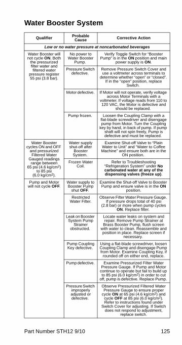
Part Number STH12 9/10 125
Water Booster System
Qualifier Probable Cause Corrective Action
Low or no water pressure at noncarbonated beverages
Water Booster will not cycle ON. Both
the pressurized filter water and filtered water
pressure register 55 psi (3.8 bar).
No power to Water Booster
Pump.
Verify Toggle Switch for “Booster Pump” is in the ON position and main
power supply is ON.
Pressure Switch defective.
Remove Pressure Switch Cover and use a voltmeter across terminals to
determine whether “open” or “closed”. If in the “open” position, replace
Switch.
Motor defective. If Motor will not operate, verify voltage across Motor Terminals with a
voltmeter. If voltage reads from 110 to 120 VAC, the Motor is defective and
should be replaced.
Pump frozen. Loosen the Coupling Clamp with a flat-blade screwdriver and disengage pump from Motor. Turn the Coupling
key by hand, in back of pump. If pump shaft will not spin freely, Pump is defective and must be replaced.
Water Booster cycles ON and OFF
and pressurized Filtered Water
Gauged readings range between
65 psi (4.6 kg/cm2) to 85 psi
(6.0 kg/cm2).
Water supply shut-off after
Booster System.
Examine Shut-off Valve to “Plain Water to Unit” and “Water to Coffee Machine” and ensure both are in the
ON position.
Frozen Water Coil.
Refer to Troubleshooting “Refrigeration System” under No carbonated water at any of the dispensing valves (freeze up).
Pump and Motor will not cycle OFF.
Water supply to Booster Pump
shut OFF.
Examine the Shut-off Valve to Booster Pump and ensure valve is in the ON
position.
Restricted Water Filter.
Observe Filter Water Pressure Gauge. If pressure drops total of 40 psi
(2.8 bar) or more when pump cycles ON. Replace filter.
Leak on Booster System Pump
Strainer obstructed.
Locate water leaks on system and repair. Remove Pump Strainer at
Brass Booster Pump, flush screen with water to clean. Reassemble and position in place. Replace screen if
necessary.
Pump Coupling Key defective.
Using a flat-blade screwdriver, loosen Coupling Clamp and disengage Pump from Motor. Examine Coupling Key, if
rounded off on either end, replace.
Pump defective. Examine Pressurized Filter Water Pressure Gauge. If Pump and Motor
continue to operate but fail to build up to 85 psi (6.0 kg/cm2) in order to cut
off, pump is defective. Replace Pump.
Pressure Switch improperly adjusted or defective.
Observe Pressurized Filtered Water Pressure Gauge to ensure proper
cycle ON at 65 psi (4.6 kg/cm2) and cycle OFF at 85 psi (6.0 kg/cm2). Refer to instructions found under
Switch Cover for adjusting. If Switch does not respond to adjustment,
replace switch.

126 Part Number STH12 9/10
Low or no water pressure at noncarbonated beverages (continued)
Pump and Motor cycles ON and OFF
excessively.
Leak on Booster System.
Locate water leaks on system and repair.
Check valve defective.
Observe Filtered Water Pressure Gauge. If pressure rises and drops
with Pressurized Filtered Water Gauge, the Water Inlet Check valve
on Pump is defective. Replace Check valve.
Pressure Switch improperly adjusted or defective.
Observe Pressurized Filtered Water Pressure Gauge to ensure proper
cycle ON at 65 psi (4.6 kg/cm2) and cycle OFF at 85 psi (6.0 kg/cm2). Refer to instructions found under
Switch Cover for adjusting. If Switch will not respond to adjustment, replace
switch.
Accumulator Tank pressure set improperly.
Push Toggle Switch and Water Shut-off Valve to Booster Pump to the
OFF position. Activate Plain Water button until water flow ceases. Using a tire gauge verify a 60 psi (4.2 kg/cm2)
charge on Tank. Recharge if necessary.
Note: When charging Accumulator Tank, only AIR should be used.
Accumulator Tank bladder
ruptured.
Repeat procedures above. If water is found inside Air Chamber when
verifying pressure charge, bladder is ruptured. Replace Accumulator Tank.
Motor overheating.
Using a flat-blade screwdriver, loosen Coupling Clamp and disengage Pump
from Motor. Turn Coupling Key by hand, in back of Pump. If Coupling Key is difficult to turn, it may cause
defective Motor to overheat. Replace Motor if necessary.
Peculiar taste in Non-carbonated
beverages.
Water Filter contaminated.
Replace Filter. Refer to Troubleshooting “Water Filter System”
under Peculiar taste.
Accumulator Tank bladder
ruptured.
Replace Accumulator Tank. Refer to “Pump and Motor Cycle ON and OFF
excessively” Accumulator Tank bladder ruptured.
Malfunction of Carbonated
Water System.
Refer to Troubleshooting “Carbonated Water System” under Peculiar taste, Probable Cause: Back Flow Preventer
leaking.
Qualifier Probable Cause Corrective Action

Part Number STH12 9/10 127
Water Filter SystemUntil repairs can be made on the Water Filter, place valve handle into “filter By-pass” position.
Qualifier Probable Cause Corrective Action
Carbon particles in finished drink.
Water By-pass valve is not in the “filtering”
position.
Verify By-pass valve handle is in the Filter “operating” position. If particles
continue to appear, filter must be serviced.
Defective or damaged seal
on Filter Cartridge.
Verify O-rings are not twisted or nicked. Verify Cartridge is solid and
free of cracks. Replace if necessary.
Filter Cartridge installed without
Inlet Seal.
Remove Cartridge from Canister. Clean Canister Lid and Shell
assembly. Replace with new Filter Cartridge, making sure to remove
Water Inlet Seal.
Defective carbonator
Pump.
Refer to Troubleshooting “Carbonated Water System”.
Defective Circulating
Pump.
Refer to Troubleshooting “Circulating System”.
Carbonator and Water Booster
Pump extremely noisy.
Restricted Water Filter.
Observe Filter Water Pressure Gauge. If pressure drops at total of 40 psi (2.8 bar) or more when pump cycles ON,
replace filter.
Filter Cartridge installed without removing Water
Inlet Seal.
Removed Cartridge from Canister. Clean Canister Lid and Shell
Assembly. Install new Filter Cartridge, making sure to remove Cartridge Inlet
Seal.
Water supply to Filer restricted.
Verify water supply is turned ON to unit. Refer to Troubleshooting
“Carbonated Water System” and “Water Booster System” for additional
solutions.
Peculiar taste. Water Filter contaminated.
Place Filter valve into “Filter By-pass” position. Replace Filter and reposition
valve handle to “filter operating” position.
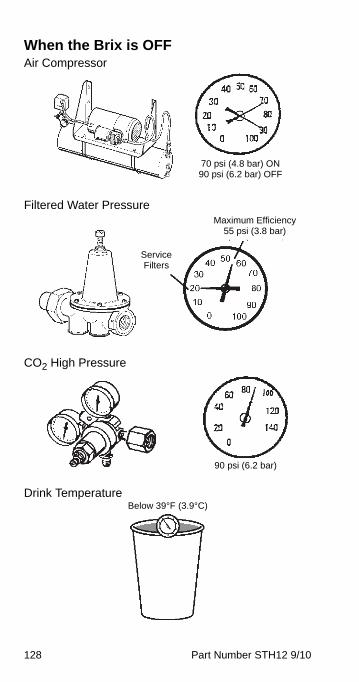
128 Part Number STH12 9/10
When the Brix is OFFAir Compressor
Filtered Water Pressure
CO2 High Pressure
Drink Temperature
70 psi (4.8 bar) ON90 psi (6.2 bar) OFF
Maximum Efficiency55 psi (3.8 bar)
Service Filters
90 psi (6.2 bar)
Below 39°F (3.9°C)
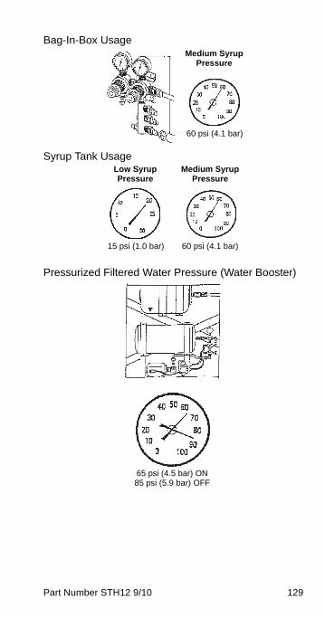
Part Number STH12 9/10 129
Bag-In-Box Usage
Syrup Tank Usage
Pressurized Filtered Water Pressure (Water Booster)
60 psi (4.1 bar)
Medium Syrup Pressure
60 psi (4.1 bar)
Medium Syrup Pressure
15 psi (1.0 bar)
Low Syrup Pressure
65 psi (4.5 bar) ON85 psi (5.9 bar) OFF
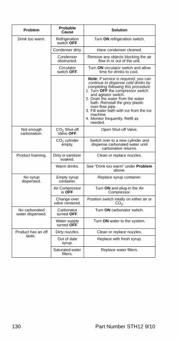
130 Part Number STH12 9/10
Problem Probable Cause Solution
Drink too warm. Refrigeration switch OFF.
Turn ON refrigeration switch.
Condenser dirty. Have condenser cleaned.
Condenser obstructed.
Remove any objects blocking the air flow in or out of the unit.
Circulator switch OFF.
Turn ON circulator switch and allow time for drinks to cool.
Note: If service is required, you can continue to dispense cold drinks by completing following this procedure.
1. Turn OFF the compressor switch and agitator switch.
2. Drain the water from the water bath. Reinstall the grey plastic over-flow pipe.
3. Fill water bath with ice from the ice machine.
4. Monitor frequently. Refill as needed.
Not enough carbonation.
CO2 Shut-off Valve OFF.
Open Shut-off Valve.
CO2 cylinder empty.
Switch over to a new cylinder and dispense carbonated water until
carbonation returns.
Product foaming. Dirty or sanitizer soaked.
Clean or replace nozzles.
Warm drinks. See “Drink too warm” under Problem above.
No syrup dispensed.
Empty syrup container.
Replace syrup container.
Air Compressor is OFF.
Turn ON and plug-in the Air Compressor.
Change-over valve centered.
Position switch totally on either air or CO2.
No carbonated water dispensed.
Carbonator turned OFF.
Turn ON carbonator switch.
Water supply turned OFF.
Turn ON water to the system.
Product has an off taste.
Dirty nozzles. Clean or replace nozzles.
Out of date syrup.
Replace with fresh syrup.
Saturated water filters.
Replace water filters.
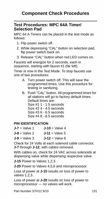
Part Number STH12 9/10 131
Component Check Procedures
Test Procedures: MPC 64A Timer/Selection PadMPC 64 A Timers can be placed in the test mode as follows:
1. Flip power switch off.
2. While depressing “CAL” button on selection pad, flip power switch back on.
3. Release “CAL” button when red LED comes on.
Faucets will energize for 2 seconds, each in sequence, starting with faucet #1 (far left).
Timer is now in the Test Mode. To stop faucets use one of two procedures:
A. Turn power switch off. This will save the programmed times, Use this procedure for testing or sanitizing.
B. Push “CAL” button. All programmed times for all stations will go to factory default times. Default times are:Size #1 1 - 1.5 seconds Size #2 4 - 4.5 seconds Size #3 6 - 6.5 seconds Size #4 8 - 8.5 seconds
PIN IDENTIFICATIONJ-7 = Valve 1 J-10 = Valve 4
J-8 = Valve 2 J-11 = Valve 5
J-9 = Valve 3 J-12 = Valve 6
Check for 24 Volts at each solenoid cable connector, J-7 through J-12, with cables removed.
With cables on, check for 24 VAC across solenoids at dispensing valve while dispensing respective valve.
J-15 Power to Valves 1,2,3.
J-20 Power to Valves 4,5,6 and microprocessor.
Loss of power at J-15 results on loss of power to valves 1,2,3.
Loss of power at J-20 results on loss of power to microprocessor — no valves will work.
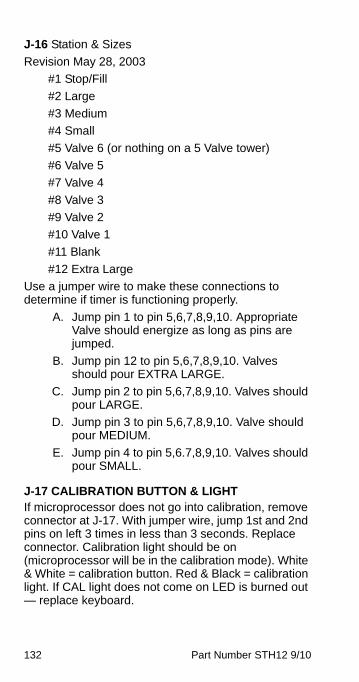
132 Part Number STH12 9/10
J-16 Station & Sizes
Revision May 28, 2003
#1 Stop/Fill
#2 Large
#3 Medium
#4 Small
#5 Valve 6 (or nothing on a 5 Valve tower)
#6 Valve 5
#7 Valve 4
#8 Valve 3
#9 Valve 2
#10 Valve 1
#11 Blank
#12 Extra Large
Use a jumper wire to make these connections to determine if timer is functioning properly.
A. Jump pin 1 to pin 5,6,7,8,9,10. Appropriate Valve should energize as long as pins are jumped.
B. Jump pin 12 to pin 5,6,7,8,9,10. Valves should pour EXTRA LARGE.
C. Jump pin 2 to pin 5,6,7,8,9,10. Valves should pour LARGE.
D. Jump pin 3 to pin 5,6,7,8,9,10. Valve should pour MEDIUM.
E. Jump pin 4 to pin 5,6.7,8,9,10. Valves should pour SMALL.
J-17 CALIBRATION BUTTON & LIGHTIf microprocessor does not go into calibration, remove connector at J-17. With jumper wire, jump 1st and 2nd pins on left 3 times in less than 3 seconds. Replace connector. Calibration light should be on (microprocessor will be in the calibration mode). White & White = calibration button. Red & Black = calibration light. If CAL light does not come on LED is burned out — replace keyboard.
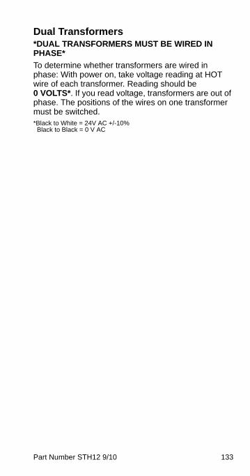
Part Number STH12 9/10 133
Dual Transformers *DUAL TRANSFORMERS MUST BE WIRED IN PHASE*
To determine whether transformers are wired in phase: With power on, take voltage reading at HOT wire of each transformer. Reading should be 0 VOLTS*. If you read voltage, transformers are out of phase. The positions of the wires on one transformer must be switched. *Black to White = 24V AC +/-10% Black to Black = 0 V AC
134 Part Number STH12 9/10
New MPC84A Portion Control BoardA new portion control board, the MPC84A, has been developed to improve the performance and maintain the functions and features of the previous MPC64A. In addition this PC board has passed the very demanding EMC testing (radio frequency emissions and interference) for European CE approval, at the UL labs. The MPC64A has been phased out as of 6/96 and only the MPC84A will be used on new production and service.
The new board is the same size, same mounting locations, and uses the same connectors as the previous board. This article is to explain some minor differences and features which can be used to your advantage.
The major difference is with the same size board, the MPC84A can control up to eight stations (dispensing valves), with up to four sizes per station. The MPC64A could only control up to six stations.
The first drawing depicts the connectors on the MPC64A.
The second drawing depicts the connectors on the MPC84A.
The Power connectors J15 and J20 (24VAC) are the same. The Keyboard connectors J16 for touchpad sizes and J17 for calibration touchpad and light, are the same.
The MPC 84A adds one more two pin keyboard connector J1. For an eight station tower, this connector, along with a separate two wire cable to the proper Keyboard, provides the two extra stations.
The five pin valve connectors, J7 to J12 on the MPC64A are changed to two pin connectors, J7 to J14 on the MPC84A. These valve connectors are not polarized (does not matter how you connect the two pins) except when the valve has a WATER or SODA harness.
The calibrating functions of the new portion control board are the same as the old board.
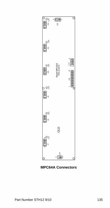
Part Number STH12 9/10 135
MPC64A Connectors
13
15
112
15
15
J20
J12
LD
6J1
1L
D5
J10
LD
4J9
LD
3J8
LD
2J7
LD
1
J15
OL
D
J16
J17
Mod
el M
PC
84A
P/N
21
3373
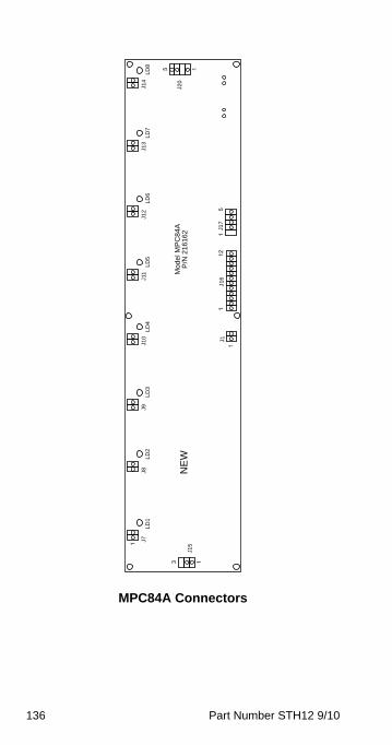
136 Part Number STH12 9/10
MPC84A Connectors
13
1
112
15
15
1
J20
J14
LD
8L
D7
LD
5J9
LD
3J8
LD
2J7
LD
1
J15
NE
W
J16
J17
Mod
el M
PC
84A
P/N
216
162
J13
J12
LD
6J1
1L
D4
J10 J1
Part Number STH12 9/10 137
FEATURES OF THE NEW MPC84A• Can control up to 8 stations (valves).
• Hardware isolation and zero switching to minimize electrical problems.
• Software improvements to noise.
CALIBRATION INSTRUCTIONS (same as MPC64A)
1. To enter calibrate mode, press calibrate switch three times in less than three seconds, and red calibrate light will illuminate.
2. Place volume cup under nozzle of the valve to be calibrated.
3. Press appropriate size switch and fill volume cup to a point just short of the calibration mark on the volume cup.
4. Let foam settle, jog size switch until liquid reaches the appropriate calibration mark on the volume cup.
5. To calibrate additional sizes, repeat steps 2 thru 4.
Special Features when in the Calibrate Mode
• To obtain an accurate 4.0 seconds pour from any valve, press its associated STOP-FILL switch once.
• To adjust all stations for the same size times, press any station STOP-FILL switch twice in less than two seconds, then repeat steps 2 thru 4 at this station. The resulting times will be copied to all stations when calibrate mode is exited.
6. To exit the calibrate mode, press calibrate switch once and red calibrate light will go out.
ImportantUse this mode, one size adjusts all, only for anemergency (no time to adjust at all) andtemporarily. Each valve flow rate, ratio, and flowregulators would have to be perfectly identical foreach valve to duplicate the same volume in thesame portion time.
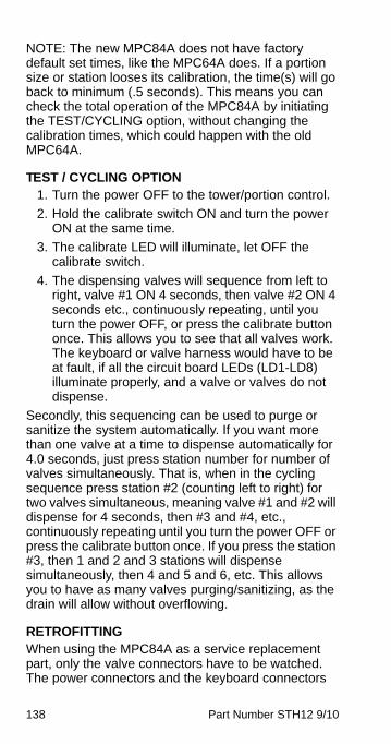
138 Part Number STH12 9/10
NOTE: The new MPC84A does not have factory default set times, like the MPC64A does. If a portion size or station looses its calibration, the time(s) will go back to minimum (.5 seconds). This means you can check the total operation of the MPC84A by initiating the TEST/CYCLING option, without changing the calibration times, which could happen with the old MPC64A.
TEST / CYCLING OPTION1. Turn the power OFF to the tower/portion control.
2. Hold the calibrate switch ON and turn the power ON at the same time.
3. The calibrate LED will illuminate, let OFF the calibrate switch.
4. The dispensing valves will sequence from left to right, valve #1 ON 4 seconds, then valve #2 ON 4 seconds etc., continuously repeating, until you turn the power OFF, or press the calibrate button once. This allows you to see that all valves work. The keyboard or valve harness would have to be at fault, if all the circuit board LEDs (LD1-LD8) illuminate properly, and a valve or valves do not dispense.
Secondly, this sequencing can be used to purge or sanitize the system automatically. If you want more than one valve at a time to dispense automatically for 4.0 seconds, just press station number for number of valves simultaneously. That is, when in the cycling sequence press station #2 (counting left to right) for two valves simultaneous, meaning valve #1 and #2 will dispense for 4 seconds, then #3 and #4, etc., continuously repeating until you turn the power OFF or press the calibrate button once. If you press the station #3, then 1 and 2 and 3 stations will dispense simultaneously, then 4 and 5 and 6, etc. This allows you to have as many valves purging/sanitizing, as the drain will allow without overflowing.
RETROFITTINGWhen using the MPC84A as a service replacement part, only the valve connectors have to be watched. The power connectors and the keyboard connectors
Part Number STH12 9/10 139
are the same and go in the same places. The older 5 pin valve connectors will fit on the new board, as long as you observe that the 5 pin connector goes on with the two wires aligned to the two pins on the new board. In case of the WATER and SODA switch harness, it must be polarized, so reverse (connector moved 180°) if WATER or SODA does not pour.

140 Part Number STH12 9/10
MOVs Field TestingMetal Oxide Varistors installed on the water and carbonated water buttons on, McDonalds style dispensing towers, are designed to completely absorb electrical spikes keeping them out of the microprocessor circuit eliminating complaints of:
• Not holding calibration
• Valves flowing by themselves
• Two valves coming on at the same time, etc.
Multiplex has designed a field test procedure that will expose a faulty MOV. This procedure will also work on the older style capacitors.
The field test procedure:
Depress separately both the water and soda water button rapidly 5 - 6 times. While doing this, watch all other valves. If you notice any dripping or any other valve trying to energize, the MOVs need to be replaced.
NOTE: Factory installed MOVs have heat shrink tubes on each terminal leg. Always check to make sure that heat shrink has not slipped down and is insulating the MOV leg inside the terminal connector.
COM NONC
MOV
Insulative Tubing
BLK
GRN/WHT
RED
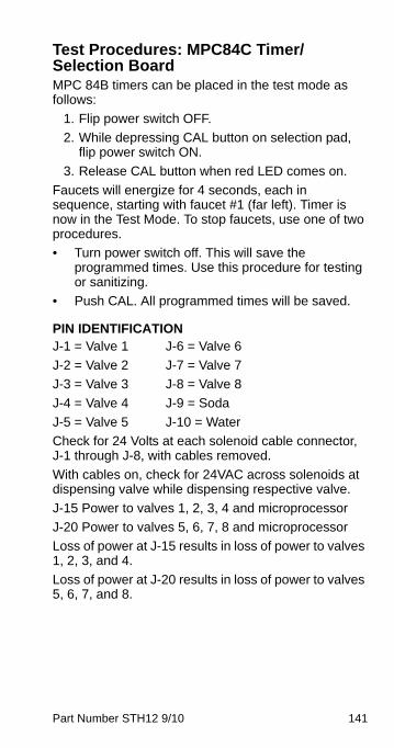
Part Number STH12 9/10 141
Test Procedures: MPC84C Timer/Selection BoardMPC 84B timers can be placed in the test mode as follows:
1. Flip power switch OFF.
2. While depressing CAL button on selection pad, flip power switch ON.
3. Release CAL button when red LED comes on.
Faucets will energize for 4 seconds, each in sequence, starting with faucet #1 (far left). Timer is now in the Test Mode. To stop faucets, use one of two procedures.
• Turn power switch off. This will save the programmed times. Use this procedure for testing or sanitizing.
• Push CAL. All programmed times will be saved.
PIN IDENTIFICATIONJ-1 = Valve 1 J-6 = Valve 6
J-2 = Valve 2 J-7 = Valve 7
J-3 = Valve 3 J-8 = Valve 8
J-4 = Valve 4 J-9 = Soda
J-5 = Valve 5 J-10 = Water
Check for 24 Volts at each solenoid cable connector, J-1 through J-8, with cables removed.
With cables on, check for 24VAC across solenoids at dispensing valve while dispensing respective valve.
J-15 Power to valves 1, 2, 3, 4 and microprocessor
J-20 Power to valves 5, 6, 7, 8 and microprocessor
Loss of power at J-15 results in loss of power to valves 1, 2, 3, and 4.
Loss of power at J-20 results in loss of power to valves 5, 6, 7, and 8.
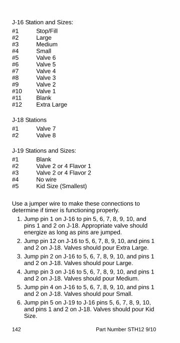
142 Part Number STH12 9/10
J-16 Station and Sizes:
#1 Stop/Fill#2 Large#3 Medium#4 Small#5 Valve 6#6 Valve 5#7 Valve 4#8 Valve 3#9 Valve 2#10 Valve 1#11 Blank#12 Extra Large
J-18 Stations
#1 Valve 7#2 Valve 8
J-19 Stations and Sizes:
#1 Blank#2 Valve 2 or 4 Flavor 1 #3 Valve 2 or 4 Flavor 2#4 No wire#5 Kid Size (Smallest)
Use a jumper wire to make these connections to determine if timer is functioning properly.
1. Jump pin 1 on J-16 to pin 5, 6, 7, 8, 9, 10, and pins 1 and 2 on J-18. Appropriate valve should energize as long as pins are jumped.
2. Jump pin 12 on J-16 to 5, 6, 7, 8, 9, 10, and pins 1 and 2 on J-18. Valves should pour Extra Large.
3. Jump pin 2 on J-16 to 5, 6, 7, 8, 9, 10, and pins 1 and 2 on J-18. Valves should pour Large.
4. Jump pin 3 on J-16 to 5, 6, 7, 8, 9, 10, and pins 1 and 2 on J-18. Valves should pour Medium.
5. Jump pin 4 on J-16 to 5, 6, 7, 8, 9, 10, and pins 1 and 2 on J-18. Valves should pour Small.
6. Jump pin 5 on J-19 to J-16 pins 5, 6, 7, 8, 9, 10, and pins 1 and 2 on J-18. Valves should pour Kid Size.

Part Number STH12 9/10 143
J-17 CALIBRATION BUTTON AND LIGHTIf microprocessor does not go into calibration, remove connector at J-17. With jumper wire, jump 1st and 2nd pins on left 3 times in less than 3 seconds. Replace connector. Calibration light should be on (microprocessor will be in the calibration mode). White & white = calibration button. Red & black = calibration light. If CAL light does not come on, LED is burned out — replace keyboard.
SECONDARY BOARD PIN IDENTIFICATIONJ-1 = Valve 2 Flavor 1
J-2 = Valve 2 Flavor 2
J-3 = Valve 4 Flavor 1
J-4 = Valve 4 Flavor 2
Use a jumper wire to make these connections to determine if timer is functioning properly.
1. Jump pin 2 or 3 on J-19 and pin 7 or 9 on J-16. Then jump pin 1 on J-16 to pin 7 or 9 on J-16. Appropriate valve should energize as long as pins are jumped.
2. Jump pin 2 or 3 on J-19 and pin 7 or 9 on J-16. Then jump pin 12 on J-16 to pin 7 or 9 on J-16. Appropriate valve should pour Extra Large.
3. Jump pin 2 or 3 on J-19 and pin 7 or 9 on J-16. Then jump pin 2 on J-16 to pin 7 or 9 on J-16. Appropriate valve should pour Large.
4. Jump pin 2 or 3 on J-19 to pin 7 or 9 on J-16. Then jump pin 3 on J-16 to pin 7 or 9 on J-16. Appropriate valve should pour Medium.
5. Jump pin 2 or 3 on J-19 to pin 7 or 9 on J-16. Then jump pin 4 on J-16 to pin 7 or 9 on J-16. Appropriate valve should pour Small.
6. Jump pin 2 or 3 on J-19 to pin 5 on J-19. Then jump pin 5 on J-19 to pin 7 or 9 on J-16. Appropriate valve should pour Kid Size.
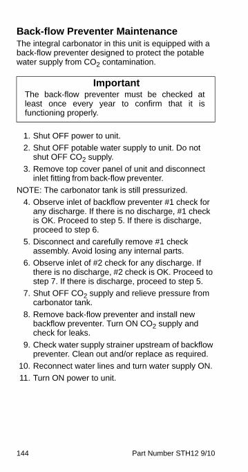
144 Part Number STH12 9/10
Back-flow Preventer MaintenanceThe integral carbonator in this unit is equipped with a back-flow preventer designed to protect the potable water supply from CO2 contamination.
1. Shut OFF power to unit.
2. Shut OFF potable water supply to unit. Do not shut OFF CO2 supply.
3. Remove top cover panel of unit and disconnect inlet fitting from back-flow preventer.
NOTE: The carbonator tank is still pressurized.
4. Observe inlet of backflow preventer #1 check for any discharge. If there is no discharge, #1 check is OK. Proceed to step 5. If there is discharge, proceed to step 6.
5. Disconnect and carefully remove #1 check assembly. Avoid losing any internal parts.
6. Observe inlet of #2 check for any discharge. If there is no discharge, #2 check is OK. Proceed to step 7. If there is discharge, proceed to step 5.
7. Shut OFF CO2 supply and relieve pressure from carbonator tank.
8. Remove back-flow preventer and install new backflow preventer. Turn ON CO2 supply and check for leaks.
9. Check water supply strainer upstream of backflow preventer. Clean out and/or replace as required.
10. Reconnect water lines and turn water supply ON.
11. Turn ON power to unit.
ImportantThe back-flow preventer must be checked atleast once every year to confirm that it isfunctioning properly.
Part Number STH12 9/10 145
Head Pressure Control ValveMultiplex remote systems require head pressure control valves with special settings. Replace defective head pressure control valves only with “original” Multiplex replacement parts.
OPERATIONThe R404A head pressure control valve is non adjustable.
At ambient temperatures of approximately 70°F (21°C) or above, refrigerant flows through the valve from the condenser to the receiver inlet. At temperatures below this (or at higher temperatures if it is raining), the head pressure control dome’s nitrogen charge closes the condenser port and opens the bypass port from the compressor discharge line.
In this modulating mode, the valve maintains minimum head pressure by building up liquid in the condenser and bypassing discharge gas directly to the receiver.
DIAGNOSING1. Determine if the coil is clean. Air passes through
the condenser from the bottom up. Verify the coil is clean by looking from the bottom up. Do not look down through the fan.
2. Determine the air temperature entering the remote condenser.
3. Determine if the head pressure is high or low in relationship to the outside temperature. (Refer to the proper “Normal Operating Pressures of Refrigeration Units” in the Charts section.)
4. Determine the temperature of the liquid line entering the receiver by feeling it. This line is normally warm; “body temperature.”
5. Using the information gathered, refer to the chart below.
NOTE: A head pressure control valve that will not bypass, will function properly with condenser air temperatures of approximately 70°F (21°C) or above. When the temperature drops below 70°F (21°C), the head pressure control valve fails to bypass and the ice machine malfunctions. Lower ambient conditions can
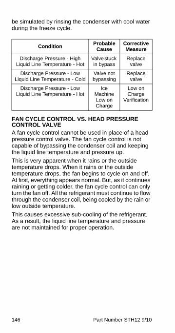
146 Part Number STH12 9/10
be simulated by rinsing the condenser with cool water during the freeze cycle.
FAN CYCLE CONTROL VS. HEAD PRESSURE CONTROL VALVEA fan cycle control cannot be used in place of a head pressure control valve. The fan cycle control is not capable of bypassing the condenser coil and keeping the liquid line temperature and pressure up.
This is very apparent when it rains or the outside temperature drops. When it rains or the outside temperature drops, the fan begins to cycle on and off. At first, everything appears normal. But, as it continues raining or getting colder, the fan cycle control can only turn the fan off. All the refrigerant must continue to flow through the condenser coil, being cooled by the rain or low outside temperature.
This causes excessive sub-cooling of the refrigerant. As a result, the liquid line temperature and pressure are not maintained for proper operation.
ConditionProbable
CauseCorrective Measure
Discharge Pressure - HighLiquid Line Temperature - Hot
Valve stuck in bypass
Replace valve
Discharge Pressure - LowLiquid Line Temperature - Cold
Valve not bypassing
Replace valve
Discharge Pressure - LowLiquid Line Temperature - Hot
Ice Machine Low on Charge
Low on Charge
Verification
Part Number STH12 9/10 147
Charging Multiplex Remote Refrigeration Unit NOTE: System would have been opened for repairs. Once completed, a vacuum of 500 microns would have been maintained for 1/2 hour. The proper procedure for charging the system includes the reintroduction of all refrigerant that had been recovered before making the repair.
1. Attach charging hose of gauge manifold to liquid valve of the recovery cylinder (if no refrigerant was in the system, and thus, no refrigerant was recovered, attach charging hose to Refrigerant cylinder). Open cylinder valve.
2. Place cylinder on charging scale-zero scale.
3. Open high side valve wheel of gauge manifold. DO NOT ATTEMPT TO CHARGE SYSTEM ON LOW SIDE—CHARGE IN A LIQUID STATE ONLY WITH REFRIGERATION SYSTEM OFF.
4. Allow sufficient time for all refrigerant to transfer from cylinder to refrigeration unit. If necessary, put cylinder into bucket of hot water to increase the internal pressure of the cylinder.
5. System total charge is the net result of:
A. Refrigeration Unit charge on nameplate
B. Remote line set length X .72 oz./ft.
C. 90% of condenser volume (cu. ft.) x Refrigerant (wt./cu ft)
NOTE: Refrigerant weight varies with temperature. R-404A weighs 72 lb/cu. ft. @ 32°; 62 lb/cu. ft. @ 95°
6. When all refrigerant has been transferred, close valve wheel of the manifold.
7. Turn refrigeration unit on.

148 Part Number STH12 9/10
Compressor & Remote Condenser
COMPRESSOR
NO
NO
NO
YES
NO
COMPRESSORWILL NOT GO
OFF
COMPRESSORWILL NOT COME
ON
VERIFY KEYPAD/DISPLAY GOOD, SEE KEYPAD / DISPLAY TROUBLE
SHOOTING PAGE 7
COMPRESSORWILL STILL NOT
GO OFF
COMPRESSORWILL STILL NOT
COME ON
YES
ELSE
VERIFY ICE BANK PROBE TIP #1 IN ICE
PULL CARB A CONN TO RESET
CONDUCTIVE PROBES
PULL ICE BANK CONN ON ERC, COMPRESSOR
SHOULD GO OFF
SHORT ICE BANK CONNECTOR #3ALL
PINS
REPLACE ICE BANK PROBE
REPLACEHPCO
SWITCH
VERIFY HPCO SWITCH
CLOSEDSHORTCONN 12
REPLACE ICE BANK PROBE
020002091
REPLACE ERC CONTROL BD
020001985
VERIFY VOLTAGE AT COMP OUTPUT
TERMINALS ON ERC
REPLACE ERC CONTROL BD 020001985
CHECKCONNECTO
RS AND WIRING TO
CONTACTORCOIL
REPLACECONTACTOR
VERIFY VOLTAGE AT CONTACTOR
COIL
VERIFY PROPER VOLTAGE AT
COMPRESSOR
REPLACECOMPRESSOR
FAN / REMOTE CONDENSER
REFRIGERATIONSYSTEM
OUTPUT TERMINALS ARE COMMON TO
COMPRESSOROUTPUT TERMINALS
ON ERC
CHECK CONNECTORS AND WIRING TO FAN /
REMOTECONDENSERCHECK
MOTORS
IF COMPRESSOR COMES ON AND STILL
NO COOLING, USE REFRIGERATION
TROUBLESHOOTING
CHECK (LIQUID LINE TEMP) AND EVAP OUT
TEMP

Part Number STH12 9/10 149
Agitator Condenser
AGITATOR
END
YESYES
NO/END
AGITATORWILL NOT GO
OFF WITH KEYPAD
BUTTON / LED
AGITATORWILL NOT
COME ON WITH KEYPAD
BUTTON / LED
VERIFY KEYPAD/DISPLAY GOOD, SEE KEYPAD / DISPLAY TROUBLE
SHOOTING PAGE 7
AGITATORWILL
STILL NOT COME ON
AGITATORWILL
STILL NOT GO OFF
REPLACEERC
CONTROLBOARD020001985
VERIFY VOLTAGE ON ERC
AGITATORTERMINALS
IF NO VOLTAGE REPLACE
ERCCONTROL
BOARD020001985
VERIFY WIRING / CONNECTORS TO
AGITATORMOTOR
REPLACEAGITATOR
MOTOR
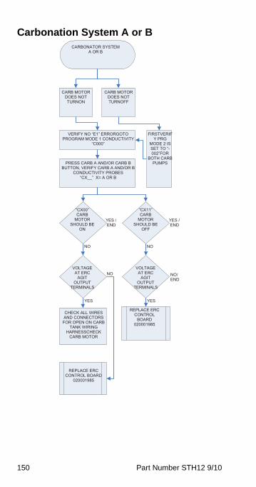
150 Part Number STH12 9/10
Carbonation System A or BCARBONATOR SYSTEM
A OR B
YES / END
NO
CARB MOTOR DOES NOT TURNON
CARB MOTOR DOES NOT TURNOFF
FIRSTVERIFY PRG
MODE 2 IS SET TO “-002”FOR
BOTH CARB PUMPS
VERIFY NO “E1” ERRORGOTO PROGRAM MODE 1 CONDUCTIVITY
“C000”
PRESS CARB A AND/OR CARB B BUTTON, VERIFY CARB A AND/OR B
CONDUCTIVITY PROBES
NO
“CX__” X= A OR B
“CX00” CARB
MOTORSHOULD BE
ON
“CX11” CARB
MOTORSHOULD BE
OFF
YES / END
VOLTAGE AT ERC
AGITOUTPUT
TERMINALS
VOLTAGE AT ERC
AGITOUTPUT
TERMINALS
NO NO/ END
YES YES
REPLACE ERC CONTROL
BOARD020001985
CHECK ALL WIRES AND CONNECTORS
FOR OPEN ON CARB TANK WIRING
HARNESSCHECKCARB MOTOR
REPLACE ERC CONTROL BOARD
020001985
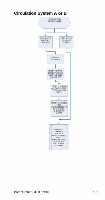
Part Number STH12 9/10 151
Circulation System A or BCIRCULATING
SYSTEM A OR B
CIRC MOTOR DOES NOT TURNON
CIRC MOTOR DOES NOT TURNON
VERIFY NO “E1” ERROR
VERIFY KEYPAD / DISPLAY WORKS, CIRC LED GOES
ON AND OFF
VERIFY VOLTAGE AT CIRC OUTPUT
TERMINALS ON ERC
CHECK ALL WIRES AND
CONNECTORS TO CIRC MOTOR, CHECK CIRC
MOTOR
REPLACEKEYPAD /
DISPLAY IF BAD 020001986
ORIFWIRES/MOTOR OK, REPLACE ERC BOARD 020001985
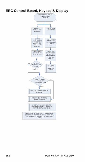
152 Part Number STH12 9/10
ERC Control Board, Keypad & DisplayERC CONTROL BOARD
AND KEYPAD / DISPLAY
KEYPAD / DISPLAY NOT
WORKING
ERC POWER LED NOT ON
KEYPAD BUTTON(S) DO NOT RESPOND,
RESPECTIVE LEDS DO NOT
COME ON
VERIFY PROPER VOLTAGE ON
ERC TERMINALS L1 AND L2
YES
NO
YES
NO
POWER ERC OFF, THEN ON,
VERIFY NO COUNTDOWN
“PdXX”ON DISPLAY
TURN POWER OFF THEN ON
TO RESET ERC
KEYPAD BUTTONS NOW
WORK REPLACE
ERCCONTROL
BOARD
DISPLAY SHOWS POWER UP
COUNTDOWN“PdXX”
REPLACE KEYPAD / DISPLAY 020001986
REPLACE ERC CONTROL BOARD 020001985
IF DISPLAY FLASHES ERRATIC NUMBERS / SYMBOLS, REPLACE
KEYPAD / DISPLAY020001986
GENERAL NOTE: FOR DISPLAY PROBLEMS, IF COUNTDOWN OCCURS ON POWER UP, “PdXX”, THEN DISPLAY IS PROBABLY AT FAULT, NOT
ERC
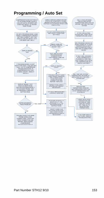
Part Number STH12 9/10 153
Programming / Auto Set
COMPRESSOR DOES NOT REACT TO ICE BANK PROBE (SODA &
CHILLER UNITS) OR BEER UNIT DOES NOT REACT TO WATER
TEMP PROBE
GO INTO PROGRAM MODE 3 AND VERIFY COMPRESSOR CONTROL
SETTING CORRECT“-003” FOR SODA & CHILLER UNITS(“-1273”
FOR BEER UNIT ONLY)
NO
YES
DISPLAY READS “-003”
F PROGRAM MODE 3 IS SET RIGHT FOR SODA / CHILLER UNIT
(“-003”), GO TO COMPRESSOR TROUBLESHOOTING, IF
COMPRESSOR STILL NOT COMING ON/OFF WHEN IT
SHOULD
DISPLAY READS “1273” WHICH IS BEER MODE
ONLYRE-PROGRAM MODE 3 TO ICE BANK PROBE “-003” BY PRESSING COMP/AGIT
BUTTON ONCE
YES / ENDREPROGRAMMINGFIXES PROBLEM
NO
TROUBLE SHOOT ICE BANK PROBE WIRING AND
CONNECTORS, LOOK FOR OPEN CONNECTION AND REPAIR / REPLACESEE
COMPRESSORTROUBLESHOOTING IF
CARB A AND/OR CARB B MOTOR STAYS ON CONSTANTLY WHEN
RESPECTIVE BUTTON ACTIVATED INSTEAD OF STOPPING WHEN CARB
TANK IS FULL
YES
YES
NO
NO
GO INTO PROGRAM MODE 2 AND VERIFY CARB PUMP
SETTINGS
PRESS CARB A/B BUTTON, DISPLAY
READS “-002”
EXIT, AND GO INTO PROGRAM MODE 1CONDUCTIVITY
“C001”PRESS CARB A/B BUTTON
DISPLAY READS “CAOO”
TROUBLE SHOOT CARB TANK WIRING HARNESS
AND CONNECTORS, LOOK FOR OPEN
CONNECTION AND REPAIR / REPLACE
REPEAT FOR CARB B SYSTEM SETTINGS IF
NECESSARY
IF “CA11” REPLACE ERC CONTROL 020001985
IF EITHER OR BOTH “0” DIGITS IS A “1”, RE-
PROGRAM TO “0” VIA PROGRAM MODE 2
INSTRUCTIONS
VERIFY CARB A & B SYSTEMS WORK NOW,
SEE CARB SYSTEM TROUBLESHOOTING IF
NECESSARY
ONLY A OR B (OR NONE) CIRCULATING WATER
TEMPERATURE DISPLAYED ON KEYPAD, UNIT HAS TWO CIRC
SYSTEM
YES
IF TWO CIRCULATING SYSTEM UNIT, VERIFY BOTH THERMISTORS ARE GOOD
ERC PROGRAM CHECKS ON EVERY POWER UP, IF GOOD
THERMISTOR(S) (0-200°F) ARE PLUGGED INTO CIRC A AND CIRC B CONNECTORS
ON ERC
IF ONLY ONE, (OR NONE) GOOD THERMISTOR IS
PLUGGED IN, THEN ONLY THAT CONNECTOR (A OR B) CIRC TEMPERATURE WILL
DISPLAY (AUTOSET)
ONLY ONE CIRC SYSTEM TEMPERATURE (OR NONE) IS DISPLAYING ON A TWO CIRC
SYSTEM UNIT
NO
REPLACE BAD THERMISTOR(S) 020001991
(NOT MEASURING 0-200°F) OR GOOD THERMISTOR(S) NOT
PLUGGED IN
VERIFY BOTH GOOD THERMISTORS ARE PLUGGED IN, THEN TURN UNIT POWER OFF, THEN ON, TO
REGISTER NEW THERMISTOR(S)
IF NO TEMP DISPLAY GO TO ERC / DISPLAY TROUBLESHOOTING
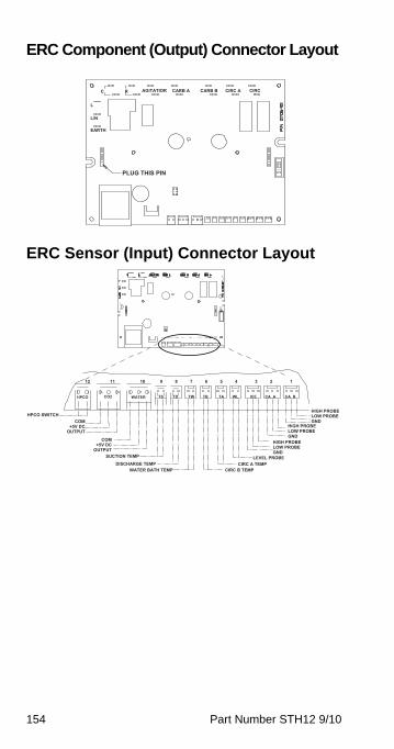
154 Part Number STH12 9/10
ERC Component (Output) Connector Layout
ERC Sensor (Input) Connector Layout
L
L/N
C R AGITATIOR CIRCB
CARB A CARB B CIRC A
EARTH
PLUG THIS PIN
12 11 10 9 8 7 6 5 4 3 2 1
CO2 TS TD TW TB TA WL ICE CA A CA B HPCO WATER
HIGH PROBE HPCO SWITCH LOW PROBE
COMHIGH PROBE
GND+5V DC
LOW PROBE OUTPUT
COM HIGH PROBE GND
+5V DC LOW PROBE OUTPUTSUCTION TEMP LEVEL PROBE
GND
DISCHARGE TEMPCIRC B TEMP
CIRC A TEMP WATER BATH TEMP

Part Number STH12 9/10 155
Component Specifications
Refrigeration Unit Specifications
Super-Chill units do not apply to the above table, they are only used to chill large amounts of water.
RATINGS
Model Number of Dispensing HeadsType of
Container
2803 One 6-valve soda tower Bag-in-Box
11M One 6-valve soda tower or up to three 2-valve root beer towers
Bag-in-Box
44M & 42M
Up to two 8-valve soda towers Bag-in-Box
50M Up to two 8-valve soda towers Bag-in-Box
ModelEvaporator Rating
at 20°F (-6.5°C)Heat Rejection (Max.)
Model 2803
2,500 BTUH 490 kcal/hr
4,500 BTUH 885 kcal/hr
Model 11M
5,150 BTUH 1,159 kcal/hr
8,638 BTUH 1,949 kcal/hr
Models 44M & 42M
9,700 BTUH 2,340 kcal/hr
13,576 BTUH 3,685 kcal/hr
Model 50M
14,900 BTUH3,310 kcal/hr
20,400 BTUH4,285 kcal/hr
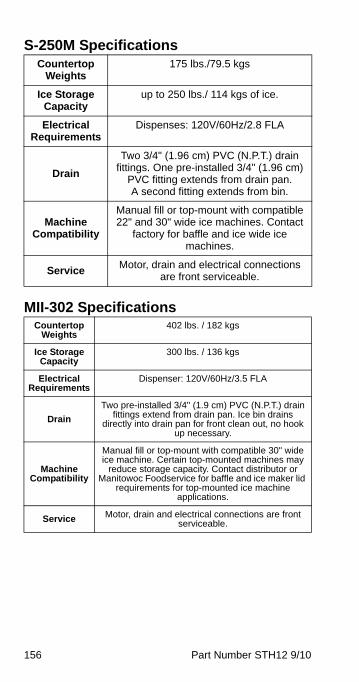
156 Part Number STH12 9/10
S-250M Specifications
MII-302 Specifications
Countertop Weights
175 lbs./79.5 kgs
Ice Storage Capacity
up to 250 lbs./ 114 kgs of ice.
Electrical Requirements
Dispenses: 120V/60Hz/2.8 FLA
Drain
Two 3/4" (1.96 cm) PVC (N.P.T.) drain fittings. One pre-installed 3/4" (1.96 cm)
PVC fitting extends from drain pan. A second fitting extends from bin.
Machine Compatibility
Manual fill or top-mount with compatible 22" and 30" wide ice machines. Contact
factory for baffle and ice wide ice machines.
ServiceMotor, drain and electrical connections
are front serviceable.
Countertop Weights
402 lbs. / 182 kgs
Ice Storage Capacity
300 lbs. / 136 kgs
Electrical Requirements
Dispenser: 120V/60Hz/3.5 FLA
Drain
Two pre-installed 3/4" (1.9 cm) PVC (N.P.T.) drain fittings extend from drain pan. Ice bin drains
directly into drain pan for front clean out, no hook up necessary.
Machine Compatibility
Manual fill or top-mount with compatible 30" wide ice machine. Certain top-mounted machines may
reduce storage capacity. Contact distributor or Manitowoc Foodservice for baffle and ice maker lid
requirements for top-mounted ice machine applications.
Service Motor, drain and electrical connections are front serviceable.
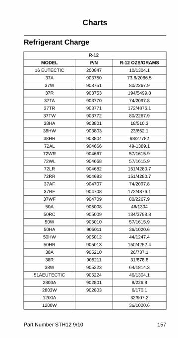
Part Number STH12 9/10 157
Charts
Refrigerant Charge
R-12
MODEL P/N R-12 OZS/GRAMS
16 EUTECTIC 200847 10/1304.1
37A 903750 73.6/2086.5
37W 903751 80/2267.9
37R 903753 194/5499.8
37TA 903770 74/2097.8
37TR 903771 172/4876.1
37TW 903772 80/2267.9
38HA 903801 18/510.3
38HW 903803 23/652.1
38HR 903804 98/27782
72AL 904666 49-1389.1
72WR 904667 57/1615.9
72WL 904668 57/1615.9
72LR 904682 151/4280.7
72RR 904683 151/4280.7
37AF 904707 74/2097.8
37RF 904708 172/4876.1
37WF 904709 80/2267.9
50A 905008 46/1304
50RC 905009 134/3798.8
50W 905010 57/1615.9
50HA 905011 36/1020.6
50HW 905012 44/1247.4
50HR 905013 150/4252.4
38A 905210 26/737.1
38R 905211 31/878.8
38W 905223 64/1814.3
51AEUTECTIC 905224 46/1304.1
2803A 902801 8/226.8
2803W 902803 6/170.1
1200A 32/907.2
1200W 36/1020.6
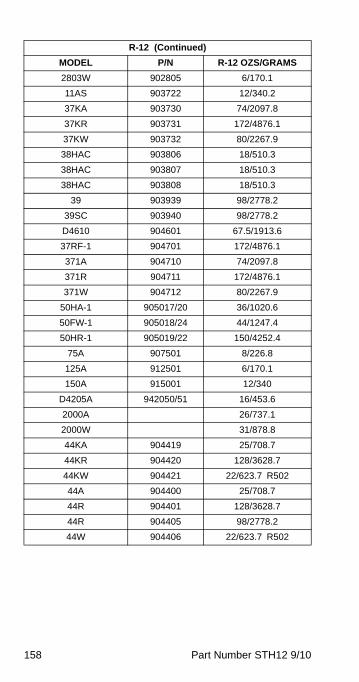
158 Part Number STH12 9/10
2803W 902805 6/170.1
11AS 903722 12/340.2
37KA 903730 74/2097.8
37KR 903731 172/4876.1
37KW 903732 80/2267.9
38HAC 903806 18/510.3
38HAC 903807 18/510.3
38HAC 903808 18/510.3
39 903939 98/2778.2
39SC 903940 98/2778.2
D4610 904601 67.5/1913.6
37RF-1 904701 172/4876.1
371A 904710 74/2097.8
371R 904711 172/4876.1
371W 904712 80/2267.9
50HA-1 905017/20 36/1020.6
50FW-1 905018/24 44/1247.4
50HR-1 905019/22 150/4252.4
75A 907501 8/226.8
125A 912501 6/170.1
150A 915001 12/340
D4205A 942050/51 16/453.6
2000A 26/737.1
2000W 31/878.8
44KA 904419 25/708.7
44KR 904420 128/3628.7
44KW 904421 22/623.7 R502
44A 904400 25/708.7
44R 904401 128/3628.7
44R 904405 98/2778.2
44W 904406 22/623.7 R502
R-12 (Continued)
MODEL P/N R-12 OZS/GRAMS
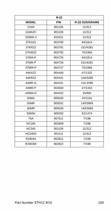
Part Number STH12 9/10 159
R-22
MODEL P/N R-22 OZS/GRAMS
11MA 901106 11/312
11MA2C 901108 11/312
150MA-1 915011 11/312
37KA22 903790 64/1814
37KR22 903791 151/4281
37KW22 903792 70/1984
37MA-P 904725 64/1814
37MR-P 904726 151/4281
37MW-P 904727 70/1984
44KA22 904440 47/1332
44KR22 904441 116/3289
44MR-G 904431 116-3289
44MR-P 904500 47/1332
44MW-G 904432 35/992
50MA 905030 42/1191
50MR 905031 140/3969
50MR 905036 140/3969
50MW 905032 52/1474
75A 907511 7/198
HC180 902809 7/198
HC340 901109 11/312
HC340S 901111 11/312
R2803A 902821 7/198
R2803W 902822 7/198

160 Part Number STH12 9/10
R-404A
MODEL P/N R-404A OZS/GRAMS
11M042C 901125 13.5/383
11MA04 901120 13.5/383
150A04 905121 13.5/383
2803A04 902830 10.5/298
2803A04B 902838 10.5/298
300MA04 930021 57/1616
3610R404C 936116 240/6804
38MA04 903850 39/1106
38MA04B 903859 39/1106
38MW04B 903855 29.5/836
38MW04 903852 26/737
44KA04 904490 57/1616
44KR04 904491 125/3544
44KW04 904492 57/1616
44MA04 904480 57/1616
44MA04E 904416 57/1616
44MR04 904481 125/3544
44MR04E 904417 125/3544
44MW04 904482 57/1616
44MW04E 904418 57/1616
450MA04 945013 113/3203
50MA04 905040 113/3203
50MR04 905041 145/4111
50MR04 905046 145/4111
50MW04 905042 113/3203
75A04 907521 10.5/298
D3610-04 936113 240/6804
D4810R04 948102 240/6804
HC900-04 903856 29/822
HC900S04 903858 29/822

Part Number STH12 9/10 161
Operating Pressures
NORMAL OPERATING PRESSURES OF REFRIGERATION UNITS
1. On system with expansion valve (pressure limiting) evaporator gets no higher than:50 psig on R-1253 psig on R-50285 psig on R-22
2. Water system head pressure should be manually set (adjustable water control valve) to maintain 105°F water condenser out temperature.
3. Remote Condenser system head pressure will be controlled by Low Ambient Control75 psig on R-12, R-134A150 psig on R-502, R-22, R-404A
R-1
2 R
-50
2 R
-22
R-1
34A
R
-404
A
Hea
d P
ress
ure
psig
ps
ig
psig
ps
ig
psig
75°
F C
onde
nser
A
mbi
ent
10
-100
% Ic
e on
E
vapo
rato
r
100-
140
200-
260
180-
240
110-
160
210-
280
90°
F C
onde
nser
A
mbi
ent
10
-100
% Ic
e on
E
vapo
rato
r
120-
170
230-
300
210-
280
130-
180
240-
320
R-1
2 R
-50
2 R
-22
R-1
34A
R
-404
A
Eva
pora
tor P
ress
ure
psig
ps
ig
psig
ps
ig
psig
75°F
Eva
pora
tor,
or 8
0°F
Wat
er75
140
130
75
150
10-1
00%
Ice
on
Eva
pora
tor
9-20
30
-50
24
-44
9-20
3
3-55
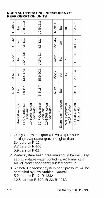
162 Part Number STH12 9/10
NORMAL OPERATING PRESSURES OF REFRIGERATION UNITS
1. On system with expansion valve (pressure limiting) evaporator gets no higher than3.4 bars on R-123.7 bars on R-5025.9 bars on R-22
2. Water system head pressure should be manually set (adjustable water control valve) tomaintain 40.5°C water condenser out temperature.
3. Remote Condenser system head pressure will be controlled by Low Ambient Control5.2 bars on R-12, R-134A10.3 bars on R-502, R-22, R-404A
R-1
2 R
-502
R
-22
R-1
34A
R
-40
4A
Hea
d P
ress
ure
bar
bar
bar
bar
bar
24°C
Con
dens
er
Am
bien
t 10
-100
% Ic
e o
n E
vapo
rato
r
6.9-
9.7
13.8
-17.
912
.4-1
6.5
7.6
-11.
014
.5-1
9.3
90°F
Con
dens
er
Am
bien
t 10
-100
% Ic
e o
n E
vapo
rato
r
8.3-
11.7
15.9
-20.
614
.5-1
9.3
8.9-
12.4
16.5
-22.
1
R-1
2 R
-502
R
-22
R-1
34A
R
-40
4A
Eva
pora
tor P
ress
ure
bar
bar
bar
bar
bar
24°C
Eva
pora
tor,
or 2
7°C
Wat
er
9.
79
10.3
10-1
00%
Ice
on
Eva
pora
tor
0.6-
1.4
2.1-
3.4
1.7-
3.0
0.4-
1.2
2.3
-3.8
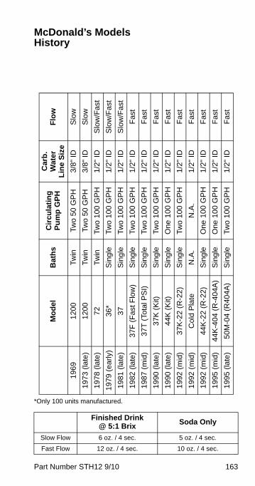
Part Number STH12 9/10 163
McDonald’s Models History
*Only 100 units manufactured.
Finished Drink @ 5:1 Brix
Soda Only
Slow Flow 6 oz. / 4 sec. 5 oz. / 4 sec.
Fast Flow 12 oz. / 4 sec. 10 oz. / 4 sec.
Mo
del
Bat
hs
Cir
cula
tin
g
Pu
mp
GP
H
Car
b.
Wat
er
Lin
e S
ize
Flo
w
1969
120
0Tw
inTw
o 50
GP
H3/
8" I
DS
low
1973
(la
te)
120
0Tw
inTw
o 50
GP
H3/
8" I
DS
low
1978
(la
te)
72Tw
inTw
o 10
0 G
PH
1/2"
ID
Slo
w/F
ast
1979
(ea
rly)
36*
Sin
gle
Two
100
GP
H1/
2" I
DS
low
/Fas
t
1981
(la
te)
37S
ingl
eTw
o 10
0 G
PH
1/2"
ID
Slo
w/F
ast
1982
(la
te)
37F
(F
ast F
low
)S
ingl
eTw
o 10
0 G
PH
1/2"
ID
Fas
t
198
7 (m
id)
37T
(To
tal P
SI)
Sin
gle
Two
100
GP
H1/
2" I
DF
ast
1990
(la
te)
37K
(K
it)S
ingl
eTw
o 10
0 G
PH
1/2"
ID
Fas
t
1990
(la
te)
44K
(K
it)S
ingl
eO
ne 1
00 G
PH
1/2"
ID
Fas
t
199
2 (m
id)
37K
-22
(R-2
2)S
ingl
eTw
o 10
0 G
PH
1/2"
ID
Fas
t
199
2 (m
id)
Col
d P
late
N.A
.N
.A.
1/2"
ID
Fas
t
199
2 (m
id)
44K
-22
(R-2
2)S
ingl
e O
ne 1
00 G
PH
1/2"
ID
Fas
t
199
5 (m
id)
44K
-404
(R
-404
A)
Sin
gle
One
100
GP
H1/
2" I
DF
ast
1995
(la
te)
50M
-04
(R40
4A)
Sin
gle
Two
100
GP
H1/
2" I
DF
ast
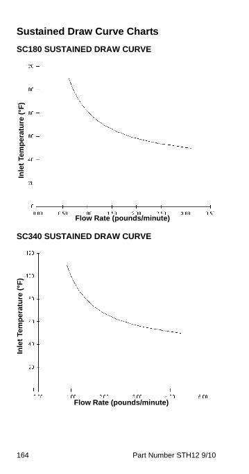
164 Part Number STH12 9/10
Sustained Draw Curve Charts
SC180 SUSTAINED DRAW CURVE
SC340 SUSTAINED DRAW CURVE
Flow Rate (pounds/minute)
Inle
t Te
mp
erat
ure
(°F
)
Flow Rate (pounds/minute)
Inle
t Te
mp
erat
ure
(°F
)
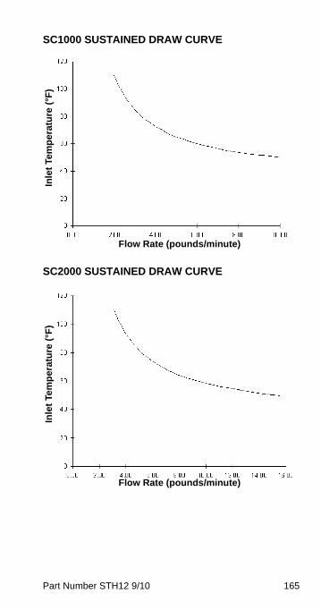
Part Number STH12 9/10 165
SC1000 SUSTAINED DRAW CURVE
SC2000 SUSTAINED DRAW CURVE
Flow Rate (pounds/minute)
Inle
t Te
mp
erat
ure
(°F
)
Flow Rate (pounds/minute)
Inle
t Te
mp
erat
ure
(°F
)

166 Part Number STH12 9/10
This Page Intentionally Left Blank
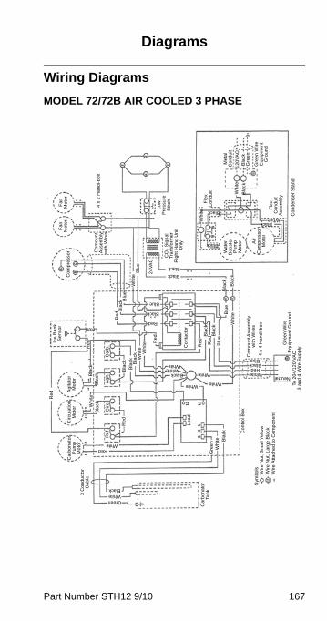
Part Number STH12 9/10 167
Diagrams
Wiring Diagrams
MODEL 72/72B AIR COOLED 3 PHASE
Lo
w
Pre
ssu
re
Stit
chC
O2 S
ign
al
Tra
nsf
orm
er
Rig
ht H
an
d U
nit
On
ly
Fa
n
Mo
tor
Fa
n
Mo
tor
Co
mp
ress
or
4 x
2 H
an
di-
bo
xC
om
ou
nt
Ass
embl
y w
ith W
ire
s
24
VA
C
Blu
eW
hite
Re
d Bla
ckB
lue
Bla
ck Bla
ck
Black
Black
Blu
eW
hite
Bla
ck
Bla
ckR
ed
Re
d
Blu
e
Black
Blue
Red
Re
d
Red
Re
d
Wh
ite
Bla
ck
Black
Black
Wh
ite
BlackWhite
Wa
ter
Boo
ste
r P
um
p
Mo
tor Air
C
om
pre
sso
r M
oto
r
12
0V
AC
Me
tal
Co
nd
uit
Bla
ck
Gre
en
Wir
e
Eq
uip
me
nt
Gro
un
d
Gre
en
Fle
x C
on
du
it A
ssem
bly
Fle
x C
on
du
it
Co
nta
cto
r
Wh
iteW
hite
Bla
ckB
lack
Bla
ck
Bla
ckBla
ck
Ag
it.C
arb
.
Re
d Ag
itato
r M
oto
rC
ircu
latio
n
Mo
tor W
hite
Bla
ck
Ice
Ba
nk
Se
nso
r
Re
f.C
irc.
Re
d
RedWhite
Ca
rbo
na
tor
Pu
mp
M
oto
r
Wh
ite Bla
ck
Gre
en
Lo
ad
Co
ntr
ol B
ox
WhiteWhite
White
WhiteWhite
Black WhiteRed
BlackBlue
NeutralC
om
ou
nt A
sse
mb
ly
with
Wir
es
4 x
4 H
an
di-
bo
x
Gre
en
Wir
e
Eq
uip
me
nt
Gro
un
dTo
20
4/1
20
VA
C
3 a
nd
4 W
ire
Su
pp
ly
Ca
rbo
na
tor
Tan
k
WhiteGreen
Black
3 C
on
du
cto
r C
ab
le
Sym
bo
lsW
ire
Nu
t, S
ma
ll Y
ello
wW
ire
Nu
t, L
arg
e B
lack
Wir
e A
ttach
ed
to
Co
mp
on
en
t
Co
nd
en
ser
Sta
nd
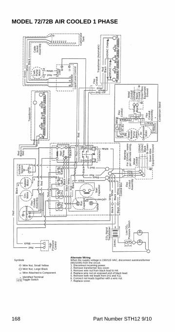
168 Part Number STH12 9/10
MODEL 72/72B AIR COOLED 1 PHASE
Symbols
Wire Nut, Small YellowWire Nut, Large Black
Wire Attached to Component
Ca
rbo
na
tor
Tan
k
Ca
ble
Ja
cke
t A
ssem
bly
Ca
rb.
Pu
mp
Mo
tor
Lo
ad
Liq
uid
Le
vel C
on
tro
l
Red
White
Gre
en W
hite
Bla
ck
RedBlack
Red
Fle
x C
on
du
itT
ran
sfo
rme
r (A
uto
ma
tic)
Bla
ckR
ed
20
8V
AC
In
pu
t2
40
VA
C O
utp
ut
Tra
nsf
orm
er
Re
d
Re
d
Re
d
Re
dB
lack
Bla
ck
Re
d
Bla
ck
Sta
rt
Re
lay
Co
nta
cto
r
White
Red
RedBlack
Black
BlackWhiteRed
Wh
iteB
lack
Black
Black
Wh
ite
White
Wa
ter
Boo
ste
r P
um
p
Mo
tor
Air
C
om
pre
ssor
M
oto
r
12
0V
AC
Me
tal
Co
nd
uit
Bla
ck
Gre
en
Wir
e
Eq
uip
me
nt
Gro
un
d
Gre
en
Fle
x C
on
du
it A
ssem
bly
Fle
x C
on
du
it
Co
nd
en
ser
Sta
nd
Bla
ck
White
Gre
en
Wir
e
Eq
uip
me
nt
Gro
un
d
Gre
en
Bla
ck1
20
VA
C1
20
VA
C
Me
tal
Co
nd
uit
Fle
x C
on
du
it A
ssem
bly
Wa
rnin
g:
Fo
r 2
20
VA
C, r
ew
ire
p
er
alte
rna
te w
irin
g.
Bla
ck
Wh
ite
Wh
ite Wh
ite
Wh
ite
Bla
ck
Bla
ckB
lack C
on
tro
l Bo
x
Wh
ite
Wh
ite
Bla
ck
Bla
ckB
lack
Re
d
Sta
rt
Ca
pa
cito
r
Ru
n
Ca
paci
tor
Black
Re
f.C
irc.
Ag
it.C
arb
.
Black
Re
d
Re
dW
hite
Bla
ckR
ed
Ice
Ba
nk
Se
nso
rA
gita
tor
Mo
tor
Cir
c.
Mo
tor
Co
mp
ress
or F
lex
Co
nd
uit
Ass
em
bly Green
Red
Black
Hig
h
Pre
ssur
e
Co
ntr
ol
CO
2 S
ign
al
Tra
nsf
orm
er
24
VA
C
Lo
w C
O2
Pre
ssu
re S
witc
h
Alternate WiringWhen the supply voltage is 230/115 VAC, disconnect autotransformer (0021035) from the circuit.1. Disconnect incoming power.2. Remove transformer box cover.3. Remove wire nut from black lead to H4.4. Replace wire nut on exposed end of black lead.5. Remove both red leads from (H1 and X1).6. Connect red leads together with a wire nut.7. Replace cover.
Identified TerminalToggle Switch
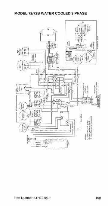
Part Number STH12 9/10 169
MODEL 72/72B WATER COOLED 3 PHASE
Lo
w C
O2
Pre
ssur
e
Stit
chC
O2 S
ign
al
Tra
nsf
orm
er
Rig
ht
Ha
nd
Un
it O
nly
Hig
h
Pre
ssu
re
con
tro
lC
om
pre
sso
r Co
mo
un
t A
sse
mbl
y w
ith W
ire
s
24
VA
C
Blu
eW
hite
Re
dB
lack B
lue
Bla
ck
Bla
ck
Black
Black
Blu
e
Wh
ite
Bla
ck
Bla
ckR
ed
Re
d
Blu
e
Black
Blue
Red
Re
d
Red
Re
d
Wh
ite
Bla
ck
Black
Black
Wh
ite
BlackWhite
Wa
ter
Bo
ost
er
Pu
mp
M
oto
r
Air
C
om
pre
sso
r M
oto
r
12
0V
AC
Me
tal
Co
nd
uit
Bla
ck
Gre
en
Wir
e
Eq
uip
me
nt
Gro
un
d
Gre
en
Fle
x C
on
du
it A
sse
mbl
y
Fle
x C
on
du
it
Co
nta
cto
r
Wh
iteW
hite
Bla
ckB
lack
Bla
ck
Bla
ckBla
ck
Ag
it.C
arb
.
Re
d Ag
itato
r M
oto
rC
ircu
latio
n
Mo
tor W
hite
Bla
ck
Ice
Ba
nk
Se
nso
r
Re
f.C
irc.
Re
d
RedWhite
Ca
rbo
na
tor
Pu
mp
M
oto
r
Wh
ite Bla
ck
Gre
en
Lo
ad
Co
ntr
ol B
ox
WhiteWhite
White
WhiteWhite
Black WhiteRed
BlackBlue
Neutral
Co
mo
un
t Ass
em
bly
w
ith W
ire
s4
x 4
Ha
nd
i-b
ox
Gre
en
Wir
e
Eq
uip
me
nt
Gro
un
dTo
20
4/1
20
VA
C
3 a
nd
4 W
ire
Su
pp
ly
Ca
rbo
na
tor
Tan
k
WhiteGreen
Black
3 C
on
du
cto
r C
ab
le
Sym
bo
lsW
ire
Nu
t, S
ma
ll Y
ello
wW
ire
Nu
t, L
arg
e B
lack
Wir
e A
ttach
ed
to
Co
mp
on
en
t
Co
nd
en
ser
Sta
nd
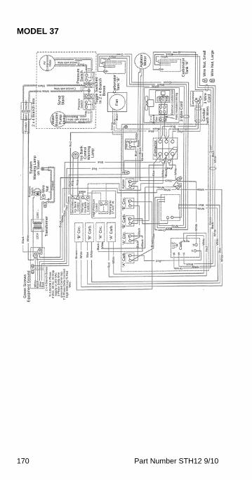
170 Part Number STH12 9/10
MODEL 37A
ir C
om
pre
sso
r M
oto
r
Black
Conduit with WireBlack
White WhiteBlack
GreenWhite
BlackGreen
Ag
itato
r M
oto
r
Ca
rbo
na
tor
Tank
“A
”
WhiteBlack
Green
Com
pre
ssor
3 W
ire
C
ord
Co
nd
uit
with
Wir
es
3 W
ire
Co
rd
Fie
ld In
sula
ted
Wiri
ng
Re
mo
ve C
on
den
ser
Ca
rbo
na
tor
Tan
k “B
”F
an
Blu
e Bla
ck
Gre
en
WhiteConduit with Wire
White
BlackConduit with Wire
Wa
ter
Boo
ste
r P
um
p
Mo
tor
Syr
up
S
tan
d
Pre
ssur
e
Sw
itch
Pre
ssu
re
Sw
itch
Tog
gle
Sw
itch
es
In 2
x 4
Bra
nch
B
oxe
s
2 x
4 B
ran
ch B
ox
Fie
ld C
onn
ectio
nC
on
duit
BlueBlack Black
Blue
Red
2 x
4
Bra
nch
B
ox
Gre
en
Bla
ckW
hite
Whi
te
Bla
ckW
hite
Blu
eC
on
tact
or
Gre
enB
lack
Bla
ckB
lue
Re
d
Re
frig
.
Re
d
Red
WhiteWhite White
Black
Ag
itato
r
Blue
Red
Re
d
Re
dR
ed
Black
WhiteBlue
WhiteBlack
Green
Wh
ite
“B”
Circ
.“B
” C
arb
.“A
” C
irc.
“A”
Ca
rb.
Bla
ck
Bla
ckB
lack
Bro
wn
Blu
e
LL
C
“A”
Ca
rb.
GreenWhite
Black
Whi
teR
ed
Whi
te
Whi
teW
hite
Bla
ckGre
en
Blu
eRed
Re
d Wh
ite
Whi
te
Bla
ck
Whi
te
Blu
e
Wh
ite
Bro
wn
“B”
Circ
.
“B”
Ca
rb.
“A”
Cir
c.
“A”
Ca
rb.
Wa
rnin
g fo
r 3
7 A
/37
W.
Hig
h P
ress
ure
C
on
tro
l
Wir
e N
ut,
La
rge
Wir
e N
ut,
Sm
all
Ice
Ba
nk
Co
ntr
ol
Wa
rnin
g
La
mp
Sys
tem
W
arn
ing
La
mp
o
n T
ow
er
Pre
ssur
e
Sw
itch Co
ndu
it
Tra
nsf
orm
er
Wir
e
Nu
t
Bla
ck
Wh
ite
12
0V1
20V
Bla
ck Whi
teB
lue R
ed
Gre
enS
eco
nda
ry
Ice
Ba
nk
Co
ntr
ol
Prim
ary
Ic
e B
ank
C
ont
rol
Gre
en
Scr
ew
s E
qu
ipm
en
t G
rou
nd
Wh
iteB
lack
Blu
eR
ed
2 x
4 B
ranc
h B
oxe
sTo
12
0/2
08
3 P
ha
se4
Wire
, 60
Hz,
30
Am
pS
upp
ly o
r 24
0 V
AC
3 P
has
e D
elta
Wire
gro
un
ded
Cen
ter
tap
.If
3 P
ha
se D
elta
Con
nec
t H
igh
Wild
Le
g T
o R
ed
Wir
e.
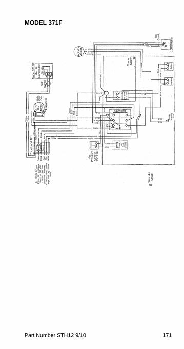
Part Number STH12 9/10 171
MODEL 371F
Contactor
Re
frig
.A
gita
tor
Gre
en
Green
BlackBlack
Gro
un
d
Scr
ew
Bla
ck
Gre
en
Blu
eBlu
eB
lue
Red
Red
Blue
Sec
on
dar
y Ic
e B
an
k C
on
tro
l
Gre
en
Green
Mo
de
l 37
1R
FM
ac.
8
Co
nd
en
ser
Fie
ld
Wir
ing
#11
R
ela
y
Blu
e
Gre
en
Bla
ckR
ed
Gre
en
Ca
paci
tor
37
AF
F
an
M
oto
r
Mod
el
371
AF
O
nly
Brown
Yel
low
Ye
llow
Wh
ite Bla
ckY
ello
wY
ello
w Gre
en
Bla
ck
Re
dB
lue White White
Blue
Blu
e
White
BlueBlackBlack
Red
Blue
Blue
Gre
en
Bla
ckR
edB
lue
Wh
ite
2 x
4 H
an
di B
ox
Gre
en
Wire
E
qui
pm
ent
Gro
und
Prim
ary
Ic
e
Ba
nk
Co
ntr
ol
To 1
20
/20
8 3
Ph
ase
4 W
ire
, 60
Hz,
30
Am
pS
upp
ly o
r 2
40 V
AC
3 P
has
e D
elta
Wire
gro
un
ded
Ce
nte
r ta
p.
If 3
Ph
ase
Del
ta C
onn
ect
H
igh
Wild
Le
g T
o R
ed
W
ire
.
Hig
h
Pre
ssur
e C
on
tro
l 2
50
PS
I
Wire
Nu
t S
ma
ll
Ref
rig
. W
arn
ing
L
amp
Red
Red
Red
BlueBlack
Co
mp
ress
orFle
x C
on
d.
Ag
itato
r M
oto
r
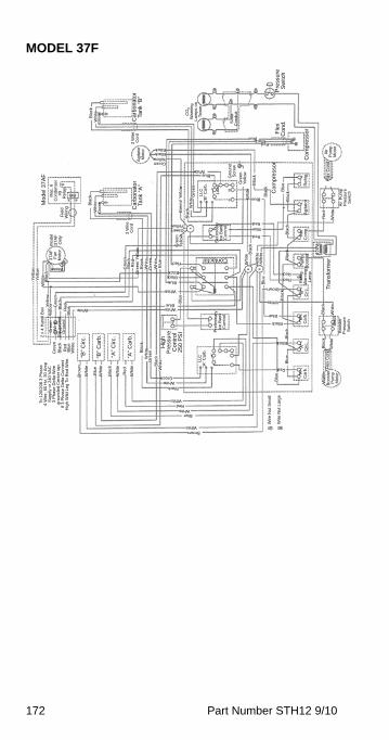
172 Part Number STH12 9/10
MODEL 37F
Contactor
Re
d
Se
con
dar
y Ic
e B
an
k C
on
tro
l
White
Wh
ite
Ye
llow
Ye
llow
Wh
ite Bla
ck
Brown
37
AF
F
an
M
oto
r
Mo
de
l 3
7A
F
Onl
y
Agi
tato
r M
oto
r
Ca
rbo
na
tor
Tan
k “A
”
3 W
ire
Co
rd
Gre
en
Wh
iteBla
ck
Fie
ld
Wir
ing
Mo
de
l 37
AF
Mac
. 6
C
ond
en
ser
#9
Re
lay
3 W
ire
Co
rdC
arb
on
ato
r Ta
nk
“B”
Gre
en
Wh
iteB
lack
BlackBlack
Green Yellow
Gre
en/
Yel
low
Bla
ckW
hite
Gre
en
BlueWhite
Green Yellow
Gre
en
Yel
low
LLC
“B
” C
arb
.
Lo
ad
Gro
un
d S
cre
w
Gre
en
Yel
low
Wh
ite
Blue
Bla
ck
Co
mp
ress
or
Bla
ck
Co
mp
ress
or
Fle
x C
on
d.
RedBlack
Blue
So
da
Co
ndu
itCO
2 W
arn
ing
La
mps
on
To
wer
Pre
ssu
re
Sw
itch
Air
Pu
mp
Mo
tor
Fle
x C
ond
.
Air
Pum
p
Pre
ssur
e
Sw
itchB
lue
Bla
ckB
lack
Red
BlueRed
Tra
nsf
orm
er
12
0V
Air
Com
p.A
gita
tor
Re
frig
.
Bla
ck
RedRed
White
Brown
Blue
Blu
e
Wh
ite
Whi
teW
hiteB
lack
Pum
p
Bo
oste
rR
efri
g.
Wa
rnin
g
Lam
p
“B”
Cir
c.
Gre
en
Bla
ckR
ed
Gre
en/
Ye
llow
Bla
ckW
hite
Gre
en
Whi
teB
lue Red
White
BlueBlack
Black
Blu
e
WhiteBlue
Pre
limin
ary
Ic
e B
an
k C
on
tro
l
Hig
h
Pre
ssu
re
Co
ntr
ol
25
0P
SI
White
Blu
eRedBla
ckG
ree
nY
ello
wYe
llow
2 x
4 H
and
i Bo
x
Gre
enB
lack
Re
dB
lue
Wh
ite
Gre
en
Wire
E
qu
ipm
ent
G
rou
nd
To 1
20/
20
8 3
Ph
ase
4 W
ire
, 60
Hz,
30
Am
pS
upp
ly o
r 2
40 V
AC
3 P
has
e D
elta
Wir
eg
rou
nd
ed C
ent
er
tap
.If
3 P
ha
se D
elta
Con
nec
t H
igh
Wild
Leg
To
Re
d W
ire
.
Bro
wn
Wh
ite
Blu
eW
hite
Bla
ck
Wh
ite
Re
d
Wh
ite
“B”
Cir
c.
“B”
Car
b.
“A”
Cir
c.
“A”
Car
b.
Bla
ckW
hite
Gre
en
Bla
ckW
hite
Black
Green
BrownWhite
BlueWhite
RedWhite
LLC
“A
” C
arb
.
Black
Black
Bla
ckB
lack
Blu
e
Blu
e
Red
“B”
Ca
rb.
“A”
Cir
c.“A
” C
arb
.
Wa
ter
Boo
ste
r P
um
p M
oto
r
Fle
x C
ond
.Bla
ck
Wh
ite
Bo
oste
r P
ress
ure
S
witc
h
Bla
ck
Whi
te
Wire
Nu
t Sm
all
Bla
ck
Wir
e N
ut L
arg
e
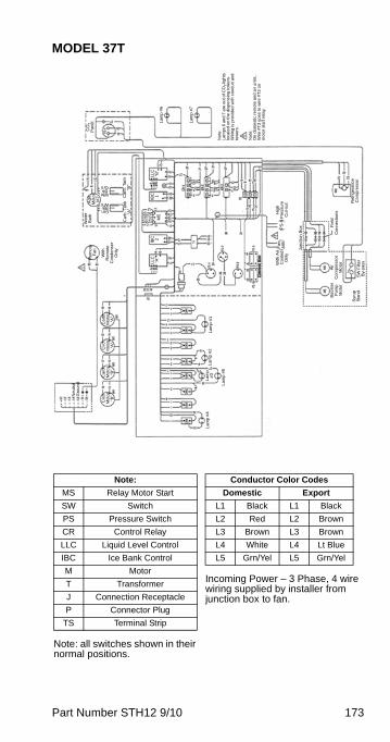
Part Number STH12 9/10 173
MODEL 37T
CO
2 P
ane
l Lam
p #
6
Lam
p #
7
Not
e:
Lam
ps 6
an
d 7
are
ou
t of C
O2
ligh
ts
loca
ted
on
the
dis
pe
nsin
g t
owe
rs.
Wiri
ng
is p
rovi
ded
with
co
ndu
it an
d
tow
ers
.
Not
e:
On
dom
est
ic r
em
ote
an
d a
ir u
nits
, W
ire #
T3
go
es
to w
ire
#T
3 o
n m
oto
r st
art
rel
ay.
Wat
er
Ba
thA
git.
M
oto
r M
7
Car
b. T
an
k “A
”C
arb
. Ta
nk
“B”
Re
mo
te
Fa
n
With
R
em
ote
C
ond
ens
er
Onl
y
Hig
h P
ress
ure
C
ut-
out
With
Air
Co
ole
d
Onl
y
Fa
n M
8P
S-6
Jun
ctio
n B
ox
GrnBlkWht
WhtBlkGrn
LLC
“B
”IB
C
1M
5
IBC
2
LLC
“A
”
Ca
rb.
Mot
or
“A”
Circ
. M
oto
r “A
”
Car
b.
Mo
tor
“B”
Cir
c.
Mo
tor
“B”N
eutr
alG
rou
nd
La
mp
#4
La
mp
#5
La
mp
#
3L
am
p #
2L
am
p #
1
Co
ntr
ol B
ox
Fie
ld
Con
nec
tion
s
Re
frig
era
tion
Com
pre
ssor
Air
Co
mp
ress
or
Mo
tor
Bo
ost
er
Pu
mp
M
oto
r
Syr
up
Sta
nd
SW
Filt
er
By-
pass
Note: all switches shown in their normal positions.
Note:
MS Relay Motor Start
SW Switch
PS Pressure Switch
CR Control Relay
LLC Liquid Level Control
IBC Ice Bank Control
M Motor
T Transformer
J Connection Receptacle
P Connector Plug
TS Terminal Strip
Incoming Power – 3 Phase, 4 wire wiring supplied by installer from junction box to fan.
Conductor Color Codes
Domestic Export
L1 Black L1 Black
L2 Red L2 Brown
L3 Brown L3 Brown
L4 White L4 Lt Blue
L5 Grn/Yel L5 Grn/Yel
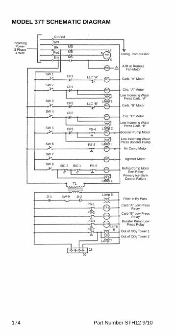
174 Part Number STH12 9/10
MODEL 37T SCHEMATIC DIAGRAM
Refrig. Compressor
AJR or Remote Fan Motor
Carb. “A” Motor
Circ. “A” Motor
Carb. “B” Motor
Circ. “B” Motor
Low Incoming Water Press Carb. “A”
Low Incoming Water Press Carb. “B”
Booster Pump Motor
Low Incoming Water Press Booster Pump
Air Comp Motor
Agitator Motor
Refrig Comp Motor Start Relay
Primary Ice Bank Control Failure
Filter In By Pass
Carb “A” Low Press Relay
Carb “B” Low Press Relay
Booster Pump Low Press Relay
Out of CO2 Tower 1
Out of CO2 Tower 2
Lamp 5
Lamp 6
Lamp 7
Lamp 4
Lamp 3
Lamp 2
Lamp 1
Grn/Yel
Wht
Blk
Red
Brn
Incoming Power
3 Phase 4 Wire
LLC “A”
LLC “B”
PS-4
PS-5
PS-6
PS-1
PS-2
PS-3
PS-7
SW-9 JI-2JI-1
99
J2
T1
IBC-2 IBC-1SW 8
SW 7
SW 6
SW 5
SW 4
SW 3
SW 2
SW 1CR1
CR1
CR2
CR2
CR3
MS
MS
MSM9
M8
M1
M2
R
M3
M4
M5
M6
M7
R
R
M5
R
A
CR1
CR2
CR3
A
A
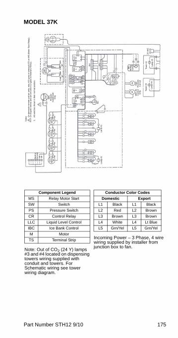
Part Number STH12 9/10 175
MODEL 37K
CO
2
Pan
el
Ag
it.
Mot
or
Ca
rb.
Tank
“A
”C
arb
. Ta
nk
“B”
Re
mot
e
Fa
n
With
R
emo
te
Co
nde
nse
r O
nly
Hig
h
Pre
ssur
e C
ut-
out
With
Air
Coo
led
O
nly
LLC
“A
”IB
C
1IB
C
2LL
C
“B”
Ca
rb.
Mo
tor
“A”
Circ
. M
oto
r “A
”
Car
b.
Mo
tor
“B”
Cir
c.
Mo
tor
“B”N
eutr
alG
rou
nd
La
mp
#2
La
mp
#1
M6
R
efr
ig.
Co
mp
Lam
p #
4
Rf
iti
Tow
er #
1
Lam
p #
3
24
VA
CTo
we
r #
2
No
tes: O
n d
om
est
ic r
em
ote
an
d a
ir u
nits
, wir
e #
13
go
es
to t
erm
ina
l #T
3 o
n M
S (
Mot
or
Sta
rt R
ela
y).
On
Exp
ort
re
mo
te a
nd
air
unit
wire
#13
goe
s to
Ne
utr
al (
TS
#11
).
2.
All
switc
hes
show
n in
the
ir n
orm
al p
osi
tion.
Note: Out of CO2 (24 Y) lamps #3 and #4 located on dispensing towers wiring supplied with conduit and towers. For Schematic wiring see tower wiring diagram.
Component Legend
MS Relay Motor Start
SW Switch
PS Pressure Switch
CR Control Relay
LLC Liquid Level Control
IBC Ice Bank Control
M Motor
TS Terminal Strip Incoming Power – 3 Phase, 4 wire wiring supplied by installer from junction box to fan.
Conductor Color Codes
Domestic Export
L1 Black L1 Black
L2 Red L2 Brown
L3 Brown L3 Brown
L4 White L4 Lt Blue
L5 Grn/Yel L5 Grn/Yel
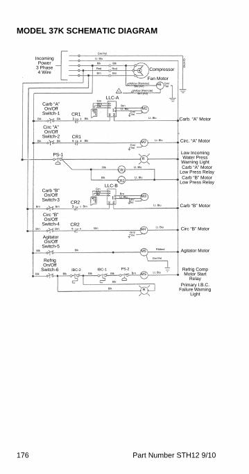
176 Part Number STH12 9/10
MODEL 37K SCHEMATIC DIAGRAM
Carb. “A” Motor
Circ. “A” Motor
Low Incoming Water Press
Warning Light
Grn/Yel
Lt. Blu
Blk
Red
Brn
Incoming Power
3 Phase 4 Wire
LLC-A
PS-1
CR1
CR1
H6
M1
R
M4
M5
IBC-2MS
Blk
Red
BrnCompressor
Fan MotorGrn/Yel
Grn
/Yel
Yellow (Remote)Blk (Air)
Yellow (Remote)Brn (Air)
Lt. Blu
Lt. BluBrn
Grn/Yel
Lt. Blu
GrnWhtBlk
Grn/Yel
M2
Blk
Carb “A” On/Off
Switch-1Blk Blk
Blk
Circ “A” On/Off
Switch-2Blk Blk
Blk
Blk
Lt. Blu
Lt. Blu
CR1
CR2
LLC-B
M3Lt. BluBrn
Grn/Yel
GrnWhtBlk
CR2Brn
Carb “B” On/Off
Switch-3Brn Brn
CR2Brn
Circ “B” On/Off
Switch-4Brn Brn
Agitator On/Off
Switch-5Blk Blk
Refrig On/Off
Switch-6Blk Blk
IBC-1 PS-2Blk Blk Brn Lt. Blu
R
Blk
Blk
Lt. Blu
Lt. Blu
Ribbed
Grn/Yel
Grn/Yel
Carb “A” Motor Low Press RelayCarb “B” Motor
Low Press Relay
Carb “B” Motor
Circ “B” Motor
Agitator Motor
Refrig Comp Motor Start
RelayPrimary I.B.C.
Failure Warning Light
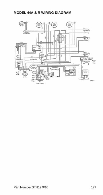
Part Number STH12 9/10 177
MODEL 44A & R WIRING DIAGRAM
Agitator Motor
Carb. Pump Motor
Circ. Pump Motor
Blk
Wht
Wh
t Blu
Wht
Blk
Wht
Ribbed Conductor
Green
BlackRed
Load
Carb. Tank Blk
Wht (Neutral)
Yellow
Brn
Yellow
Remote Condenser Model 44A
Only
Wht
Field Wire
“J” BoxLine
230 VAC 60 Hz 1 Ph
Start Relay
Model 44 R Only
Start Cap.
Run Cap. Capacitor
Box (See Cover)
Compressor
Model 44 A Only
Cond. FanBlk
Brn
BluRed
Blk
Term
Term Block B
lk
Brn
Brn
Contactor
Carb. Pump Motor
Black
Black
Black
Black
Agitator
Carb. A
Black
BrnCirculator
Brn
Brn
High Pressure Limit Switch
Model 44 A Only
Ice Bank Control
Refrig.
BrnYellow
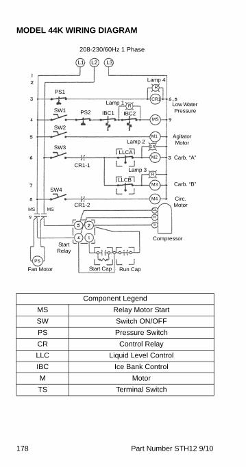
178 Part Number STH12 9/10
MODEL 44K WIRING DIAGRAM
Component Legend
MS Relay Motor Start
SW Switch ON/OFF
PS Pressure Switch
CR Control Relay
LLC Liquid Level Control
IBC Ice Bank Control
M Motor
TS Terminal Switch
208-230/60Hz 1 Phase
L1 L2 L3
Lamp 4
Lamp 2
Lamp 1
Lamp 3
PS1
SW1
SW2
SW3
PS2 IBC1 IBC2
R
R
CR1
MS
M1
M2
GR
R
M3
M4
CL
R
S
SW4
CR1-1
CR1-2
LLCA
LLCB
Start Relay
Fan Motor
MS MS
PS
Start Cap Run Cap
Compressor
Circ. Motor
Carb. “B”
Carb. “A”
Agitator Motor
Low Water Pressure
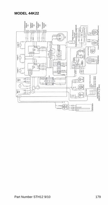
Part Number STH12 9/10 179
MODEL 44K22
Com
pre
ssor
S
witc
h
#1
Ag
itato
r S
witc
h
#2
Ca
rbo
na
tor
Sw
itch
#
3
Cir
cula
tor
Sw
itch
#
4
La
mp
4L
am
p 3
La
mp
2
LL
C
“B”
L o a d
Ribbed
LL
C
“A”
L o a d
Gre
enR
ed
Bla
ck
CR
1
Gro
un
d
Scr
ew
Blue
Brown
Black
HS
IBC
#
2IB
C
#1
Black
Ribbed Ag
it.
Mo
tor
M1
Ca
rbo
na
tor
BlackWhiteRed
Green
Car
b.
Mo
tor
“B”
M2
Cir
c.
Mot
or
M2
Car
b.
Mo
tor
“A”
M2
Jun
ctio
n B
ox
Inco
min
g P
ow
er
20
8/2
30
I.P
. H
. (2
Wir
e)
Gre
en
/Ye
llow
(G
rou
nd
)B
row
nB
lue
Re
mo
te F
an
(Y
ello
w)
Re
mo
te F
an
(Y
ello
w)
Bla
ckB
row
n
Bla
ckB
lue
Re
d
Gre
en
Yel
low
Bla
ck
Re
lay
Bla
ck
Bla
ck Bla
ck
Gre
en/
Ye
llow
BlueBlack
Red
Co
mp
ress
or
Fa
n
Mo
tor
M5
Air
Co
mp
. M
oto
r M
6
Wat
er
Bo
ost
er
Mo
tor
M7
Blue
Blue
Brown
BlackBla
ck
Blu
e
Bro
wn
Bla
ck
Bro
wn
Blu
e
Blu
e
Hig
h P
ress
ure
C
ut-
ou
tS
witc
h/J
un
ctio
n B
ox
(Op
tion
al)
(Op
tion
al A
ir C
om
pre
ssor
an
d W
ate
r B
oos
ter)
Bla
ck
Ru
n
Cap
aci
tor
Sta
rt
Cap
aci
tor
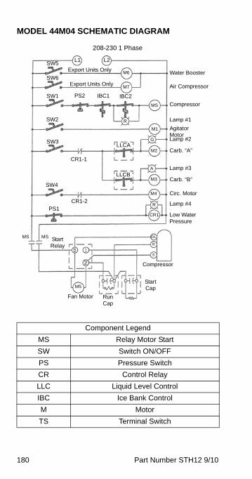
180 Part Number STH12 9/10
MODEL 44M04 SCHEMATIC DIAGRAM
Component Legend
MS Relay Motor Start
SW Switch ON/OFF
PS Pressure Switch
CR Control Relay
LLC Liquid Level Control
IBC Ice Bank Control
M Motor
TS Terminal Switch
208-230 1 Phase
L1 L2
Export Units OnlySW5
SW6
SW1
SW3
PS2 IBC1 IBC2
R
MS
M1
M2
G
A
M3
M4
CR1
R
S
SW4
CR1-1
CR1-2
LLCA
LLCB
Start Relay
Fan Motor
MS MS
Start Cap
Run Cap
Compressor
Circ. Motor
Carb. “B”
Carb. “A”
Agitator Motor
Water Booster
SW2
Export Units Only
M6
M7
R
OL
PS1
Air Compressor
Compressor
Lamp #1
Lamp #2
Lamp #3
Lamp #4
Low Water Pressure
M5
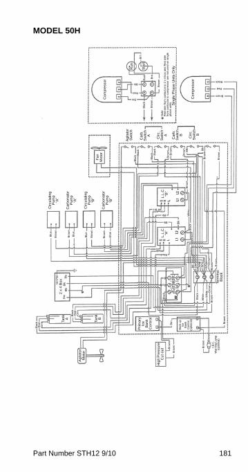
Part Number STH12 9/10 181
MODEL 50H
Co
mp
ress
or
Ru
n
Sta
rt
Sin
gle
Ph
ase
Un
its O
nly
Brn
Brn
Red
Bro
wn
Bla
ck
Bro
wn
Brn
Red
Blk
Brown
Red
Black
Co
mp
ress
or
Fa
n
Mo
tor
Ag
itato
r S
witc
h
Ca
rb.
Sw
itch
A
Cir
c.
Sw
itch
A
Ca
rb.
Sw
itch
B
Cir
c.
Sw
itch
B
Bla
ck Bla
ck
Bla
ck Bla
ck
Bro
wn
Bro
wn
Bro
wn
Blk Blk
Bro
wn
Bro
wn
Bro
wn
Wh
iteB
lack
Whi
te
Cir
cula
ting
P
um
p
“A”
Ca
rbo
na
tor
Pu
mp
“A
”
Cir
cula
ting
P
um
p
“B”
Ca
rbo
na
tor
Pu
mp
“B
”
Bro
wn
Bro
wn
Bro
wn
Bro
wn
Blu
e
Blu
e
Blu
e
Blu
e
L.L
.C
“B”
Blk
L.L
.C
“A”
Blk
RedBrn
Blk
Black
RedGreen
Co
nta
cto
r
Grn
/Ye
l
Blu
Blk
Blk
Brn
2 x
4 B
ox
Bla
ckR
ed
Grn
Tan
k A
Bla
ckR
edG
rn
Tan
k B
Ag
itato
r M
oto
r
Pri
mar
y Ic
e
Ba
nk
Co
ntr
ol
Hig
h P
ress
ure
C
ut-
ou
t Bro
wn
Bro
wn
Brn
Ba
ck u
p
Ice
Ban
k C
ont
rol
(opt
ion
al)
Bro
wn
Bro
wn B
row
n
I.B
.C.
War
nin
g L
am
p
(op
tion
al)
Term
ina
l B
lock
Bro
wn
Bro
wn
Bro
wn
Bro
wnBro
wn
Wh
iteW
hite
Whi
teWh
t
Bla
ck
Bla
ck
Blk
Blk
Blk W
ht
Wh
t
Brn
Red
No
te:
Re
d w
ire
fro
m c
ont
act
or
to 2
x 4
bo
x an
d R
ed w
ire
fro
m c
on
tact
or
to c
om
pre
sso
r a
re n
ot u
sed
on
sin
gle
p
hase
un
its.
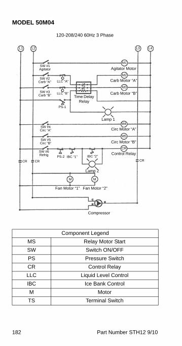
182 Part Number STH12 9/10
MODEL 50M04
Component Legend
MS Relay Motor Start
SW Switch ON/OFF
PS Pressure Switch
CR Control Relay
LLC Liquid Level Control
IBC Ice Bank Control
M Motor
TS Terminal Switch
120-208/240 60Hz 3 Phase
L1 L2
SW #1 Agitator
PS-1
LLC “A”
CR CR
Compressor
LLC “B”
SW #2 Carb “A”
SW #3 Carb “B” Time Delay
Relay
L3 L4
Carb Motor “B”
Carb Motor “A”
Agitator Motor
M1
M2
M3
Lamp 1
Circ Motor “B”
Circ Motor “A”M4
M5
CR
SW #4 Circ “A”
SW #5 Circ “B”
SW #6 Refrig
Lamp 2
Fan Motor “1” Fan Motor “2”
PS-2 IBC “1”CR
Control RelayIBC “2”
M M
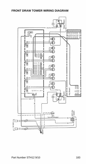
Part Number STH12 9/10 183
FRONT DRAW TOWER WIRING DIAGRAM
Grn/Yel
Re
d
BlkWa
ter
Sw
itch
Key
Boa
rd
Sod
a S
witc
h
C o n t r o l
OF
F-O
N
Sw
itch
Sp
lice
Blk
Brn
Red
Org
Ye
lG
rnB
luV
ioG
ryW
ht
BlkB
lkW
ht
BlkBrnRedOrgYelGrnBluVioGryWht
Blk
WhtWhtRedBlk
Red
Blu
Wht
Blk
Wht
Blk
Wht
Blk
Wht
Blk
Red
Blu
Wht
Wht
Red
Blk
Grn
/Ye
l Blk
Blk
Blk Blk
Blk
Grn
/Ye
lWhtBlk
WhtBlk24
VA
C
Wht
Wht
(Optional use) CO2 Light
Blk
Red
Whi
teW
hiteLD
1LD
2LD
3LD
4LD
5L
D6
J20
J15
J16
J17
WS
WS
WS
WS
WS
WS
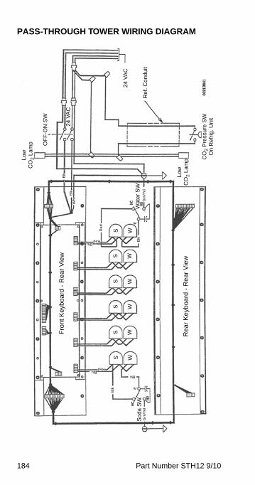
184 Part Number STH12 9/10
PASS-THROUGH TOWER WIRING DIAGRAM
24
VA
C
Ref
. Co
ndui
t
OF
F-O
N S
W
24
VA
C
Low
C
O2
Lam
p
Low
C
O2
Lam
p CO
2 P
ress
ure
SW
O
n R
efr
ig. U
nit
Wa
ter
SW
.G
rn/Y
el
Re
d
Wh
tB
lk
Blk
RedBlu B
lk
S W
S W
S W
S W
S W
S W
Fro
nt
Key
boa
rd -
Re
ar
Vie
w
Re
ar
Ke
yboa
rd -
Re
ar
Vie
w
RedBlu
BlkB
lk
Grn
/Ye
lS
oda
SW
.
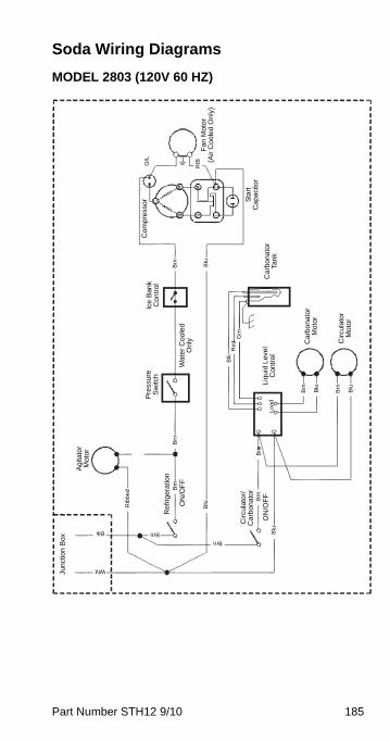
Part Number STH12 9/10 185
Soda Wiring Diagrams
MODEL 2803 (120V 60 HZ)
Fan
Mot
or
(Air
Coo
led
On
ly)
Sta
rt
Cap
acito
r
Com
pres
sor
O/L
RIB
Ca
rbo
nato
r Ta
nk
Ice
Ban
k C
ont
rol
Brn Blu
Wat
er
Coo
led
Onl
y
Pre
ssu
re
Sw
itch
Liqu
id L
evel
C
ontr
ol
Car
bona
tor
Mot
or
Cir
cula
tor
Mot
or
Blk
Re
dG
rn
Brn
Blu
Brn
Blu
Brn
Brn
Brn
Brn
Blu
Blu
Ag
itato
r M
otor
Rib
be
d
Brn
Brn
Blk
Wht
Junc
tion
Box
Re
frig
erat
ion
ON
/OF
F
ON
/OF
F
Cir
cula
tor/
Car
bon
ator
Lo
ad
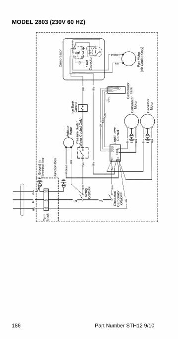
186 Part Number STH12 9/10
MODEL 2803 (230V 60 HZ)
Fan
Mo
tor
(Air
Coo
led
Onl
y)
Sta
rt
Ca
paci
tor
Com
pres
sor O
/L
Ye
l
Car
bona
tor
Tank
Ice
Ban
k C
ontr
ol
Brn Blu
Pre
ssur
e S
witc
h (W
ater
Coo
led
On
ly)
Liq
uid
Lev
el
Con
trol
Ca
rbon
ato
r M
oto
r
Cir
cula
tor
Mo
tor
Blk
Re
dG
rn
Brn
Blu
Brn
Blu
Brn
Rib
be
d
Blu
Brn
Blu
Blu
Agi
tato
r M
oto
r
Brn
Term
B
lock
Ref
rig
ON
/OF
F
Circ
ula
tor/
Ca
rbon
ato
r O
N/O
FF
Lo
ad
Brn
Brn
Brn
Grn
Gro
und
in
Ele
ctric
al B
ox
Junc
tion
Bo
x
Blk
Brn
BluR
ed
Ribbed
Blk

Part Number STH12 9/10 187
MODEL 2803 INTERNATIONAL (230V 50 HZ)
Fan
Mot
or
(Air
Coo
led
Onl
y)
Sta
rt
Ca
paci
tor
Com
pres
sor O
/L
Ca
rbo
nato
r Ta
nk
Ice
Ba
nk
Con
trol
Brn Blu
Pre
ssu
re S
witc
h
(Wat
er C
ool
ed
Onl
y)
Liq
uid
Lev
el
Con
trol
Car
bon
ator
M
oto
r
Circ
ulat
or
Mot
or
Blk
Re
dG
rn
Brn
Blu
Brn
Blu
Rib
be
d
Blu
Brn
Blu
Blu
Ag
itato
r M
otor
Brn
Term
B
lock
ON
/OF
F
Ref
rig
ON
/OF
F
Circ
ulat
or/
Car
bona
tor
Lo
ad
Brn
Brn
Brn
Grn
Gro
und
in E
lect
rica
l Box
Jun
ctio
n B
ox
Blk
Ribbed
Blk
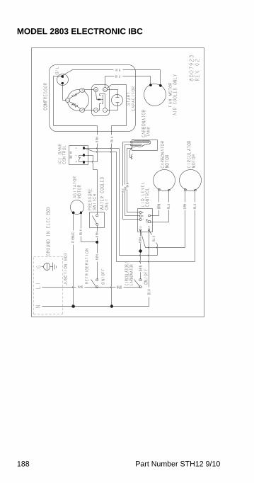
188 Part Number STH12 9/10
MODEL 2803 ELECTRONIC IBC
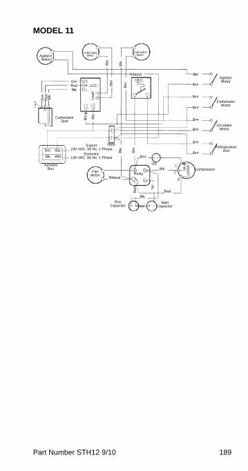
Part Number STH12 9/10 189
MODEL 11
Agitator Motor
Carbonator Motor
Carbonator Motor
Agitator Motor
Carbonator Motor
Circulator Motor
Refrigeration Unit
Carbonator Tank
Compressor
Run Capacitor
Start Capacitor
Relay
O/L
Fan Motor
Junction Box
I.B.C.
Ribbed
LCC
Lo
ad
Blk
Brn
Brn
Brn
Brn
Brn
Brn
BrnBrn
Ribbed
Blk
Red
Red
Blk
Brn Blu
Blk Wht
Blu
Brn
Re
d Ye
l
Blu
Brn
BrnB
rnB
lu
Blu
Blk
Re
d
GrnRedBlk
Term
Grn
Export230 VAC, 50 Hz, 1 Phase
Domestic120 VAC, 60 Hz, 1 Phase

190 Part Number STH12 9/10
MODEL 11 ELECTRONIC IBC(BLK)
(BRN)
(BLK)
(RED)
(BLUE)
(BLK)
(YEL)
(RED)
(L1)
USED ON MODELS
SS901120
SS901122
SS901139
ONLY
(RIBBED)
(213)
(L2
& N)
(132)
(SMOOTH)
(211)
(293)
(BRN)
(215)
(130)
(217)
(219)
(293)
(292)
(RIBBED)
(BRN)
(292)
(291)
(290)
(373)
(374)
(371)
(370)
(GRN)
(RED)
(BLK)
(GRN)
(RED)
(BLK)
SS901125 ONLY
(RED)
CARB
MOTOR A
CARB
SWITCH
SW2
MODEL 11M R404A
WIRING DIAGRAM
120V/60Hz/1PH
230V/50Hz/1PH
230V/60Hz/1PH
8014273
REV 04
CAUTION: DISCONNECT POWER BEFORE WORKING
ON ELECTRICAL CIRCUITRY.
3 1 5IBC-1
SENSOR
FAN
MOTOR
CIRC
MOTOR
START
CAP
RUN
CAP
R
C
S
COMPRESSOR
CARB
SWITCH
SW5
AGITATOR
SWITCH
SW1
REFRIGERATION
SWITCH
SW4
CIRCULATOR
SWITCH
SW3
AGITATOR
MOTOR
2 1RELAY
5 4
TS-1
O/L
LC H L
NL N
LLC-A
LC H L
NL N
LLC-B
CARB
A
CARB
B
CARB
MOTOR B
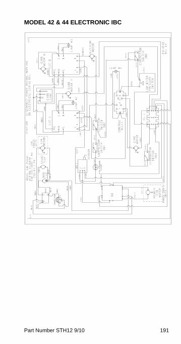
Part Number STH12 9/10 191
MODEL 42 & 44 ELECTRONIC IBC
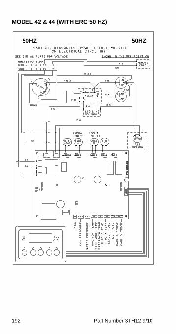
192 Part Number STH12 9/10
MODEL 42 & 44 (WITH ERC 50 HZ)
50HZ 50HZ
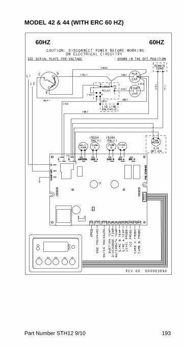
Part Number STH12 9/10 193
MODEL 42 & 44 (WITH ERC 60 HZ)
60HZ 60HZ

194 Part Number STH12 9/10
MODEL 44 (120V 60 HZ)
Component Legend
MS Relay Motor Start
SW Switch ON/OFF
PS Pressure Switch
CR Control Relay
LLC Liquid Level Control
IBC Ice Bank Control
M Motor
TS Terminal Switch
L1 L2
M8
M7
MS
M1
R
G
M2
Export Units only
Export Units only
SW5
SW6
SW1
SW2
SW3
PS2 IBC1 IBC2
Water Booster
Air Compressor
Compressor
Lamp #1
Lamp #2
Agitator Motor
Carb “A”
Lamp #3
Carb “B”
Lamp #4
Circ Motor
Low Water Pressure
MS
M4
CR1
A
R
LLCA
LLCB
CR1-1
CR1-2
SW4
PSI
MS MS Start Relay
Compressor
Start Cap
Run CapFan Motor
MS
OL
R
S
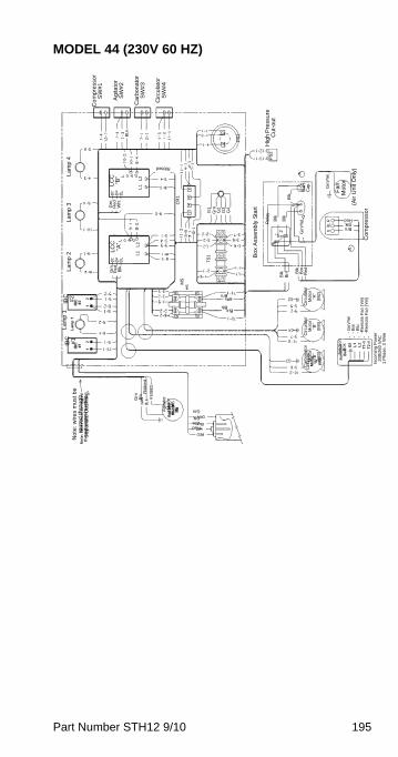
Part Number STH12 9/10 195
MODEL 44 (230V 60 HZ)
Co
mp
ress
or
SW
#1
Ag
itato
r S
W#
2
Ca
rbo
na
tor
SW
#3
Cir
cula
tor
SW
#4
Hig
h P
ress
ure
C
ut-
ou
t
Fa
n
Mo
tor
(Air
Un
it O
nly
)
Co
mp
ress
or
Bo
x A
sse
mbl
y S
tart
PS
1
PS
2
AS
tart
C
ap
A
Grn
/Yel
Grn
/Ye
l
Re
lay
Blk
Blk
2
Blk
Blk
Brn B
lkB
rnR
ed
BrnBlkRed
Circ
ula
tor
Mo
tor
“A”
(M2
)
Cir
cula
tor
Mot
or
“B”
(M4
)
Car
bon
ato
rM
oto
r “B
” (M
3) Ju
nct
ion
Box
- G
rn/Y
el-
Brn
- B
lu-R
em
ote
Fa
n (Y
el)
-Re
mo
te F
an
(Yel
)
Inco
min
g P
owe
r2
08
/26
0 V
AC
1 P
ha
se,
2 W
ire
Ag
itato
rM
oto
r M
5
RedWhtBlk
Grn
Grn
Blk
Rib
be
d
No
te: w
ire
s m
ust
be
ro
ute
d t
hro
ug
h
sepa
rate
bu
shin
g,
IBC
#
1IB
C
#2
La
mp
1L
am
p 2
La
mp
3L
am
p 4
LC
C
“A”
LC
C
“B”
MS
L o a d
L o a d
CR
1
TS
1
Grn
Re
dW
ht
Grn
Re
dB
lk
Ribbed
G1
Grn
G2
G3
G4
L1
L2
L1
L2
Brn
Blk

196 Part Number STH12 9/10
MODEL 50 (50 HZ)
50HZ 50HZModels
50MAX04 TS905053-35350MRX04 TS905054-35350MWX04 TS905055-353
Caution: Disconnect power before working on electrical circuitry.
See Serial Plate for Voltage Shown in the OFF PositionPower Supply Block
Terminal Strip
Remote Cond
Air Option
Fan Motor
Fan Motor
(Black)
(Black)
Contactor
Refrigeration Agitator Switch
HPCO
IBC Contactor Coil
RMT Only Liquid Line Solenoid
AGT Motor
Low Water Pressure Relay Coil
Low Water Pressure Switch
Carb A Motor
Load
Load Carb B Motor
Circ A Motor
LLC
(Grn)
(Red)
(Blk)
Tank A
Tank B
LLC
(Grn)
(Red)
(Blk)
Carb Motor A Switch
Circ Motor A Switch
LWPR
LWPR Carb Motor B Switch
Circ Motor B Switch
Circ B Motor
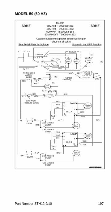
Part Number STH12 9/10 197
MODEL 50 (60 HZ)
60HZ 60HZModels
50MA04 TS905050-36350MR04 TS905051-36350MW04 TS905052-363
50MR04Q/T TS905046-263
Caution: Disconnect power before working on electrical circuitry.
See Serial Plate for Voltage Shown in the OFF Position
Remote Cond
Air Option
Fan Motor
Fan Motor
(Black)(Black)
Contactor
Refrigeration Agitator Switch
HPCO
IBCContactor Coil
RMT Only Liquid Line Solenoid
AGT Motor
Low Water Pressure Relay
Coil
Low Water Pressure Switch
Carb A Motor
Load
Load Carb B Motor
Circ A Motor
LLC A
(Grn)
(Red)
(Blk)
Tank A
Tank B
LLC B
(Grn)
(Red)
(Blk)
Carb Motor A Switch
Circ Motor A Switch
LWPR
LWPR Carb Motor B Switch
Circ Motor B Switch
Circ B Motor
Sensor
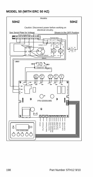
198 Part Number STH12 9/10
MODEL 50 (WITH ERC 50 HZ)
50HZ 50HZModels
Caution: Disconnect power before working on electrical circuitry.
See Serial Plate for Voltage Shown in the OFF PositionPower Supply Block
Terminal Strip
Remote Cond
Air Option
Fan Motor
Fan Motor
(Black)
(Black)
Contactor
Contactor Coil
RMT Only Liquid Line Solenoid
AGT Motor
P/N 020001985
Jumper
Carb A
Carb A
Circ A
Circ B
Agitator Carb A Carb A Circ A Circ B
P/N 020001986
HP
CO
CO
2 P
ress
ure
Wa
ter
Pre
ssu
re
Su
ctio
n T
em
pD
isch
arg
e T
em
pW
ate
rba
th T
em
pC
irc
B T
em
p
Cir
c A
Te
mp
Le
vel P
rob
e
Ice
Pro
be
Ca
rb A
Pro
be
Ca
rb B
Pro
be
P/N
07
05
-10
1
Earth
RC
L/N
L

Part Number STH12 9/10 199
MODEL 50 (WITH ERC 60 HZ)
60HZ 60HZModels
Caution: Disconnect power before working on electrical circuitry.
See Serial Plate for Voltage Shown in the OFF Position
Remote Cond
Air Option
Fan Motor
Fan Motor
(Black)(Black)
Contactor
Contactor Coil
RMT Only Liquid Line Solenoid
AGT Motor
P/N 020001985
Carb A
Carb A
Circ A
Circ B
Agitator Carb A Carb A Circ A Circ B
P/N 020001986
HP
CO
CO
2 P
ress
ure
Wa
ter
Pre
ssur
e
Su
ctio
n T
em
pD
isch
arg
e T
em
pW
ate
rba
th T
em
pC
irc
B T
em
p
Cir
c A
Te
mp
Le
vel P
rob
e
Ice
Pro
be
Ca
rb A
Pro
be
Ca
rb B
Pro
be
P/N
07
05
-10
1
Earth
RC
L/N
L

200 Part Number STH12 9/10
Super-Chil Wiring Diagrams
MODEL SC180 (120 VAC)
Component Legend
L1 Line 1
L2 Neutral
M Motor
MS Contactor
PS Pressure Switch
IBC Ice Bank Control
Optional Circulator
Motor
Agitator MotorStart Relay
Compressor
Run Cap Start Cap
Fan
IBCPS
L1 L2
M
MS
M1
SW4
SW1
SW2
M5
MS MS
OL
R
S

Part Number STH12 9/10 201
MODEL SC180 ELECTRONIC IBC
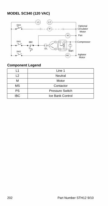
202 Part Number STH12 9/10
MODEL SC340 (120 VAC)
Component Legend
L1 Line 1
L2 Neutral
M Motor
MS Contactor
PS Pressure Switch
IBC Ice Bank Control
Optional Circulator
Motor
Agitator Motor
CompressorIBC
L1 L2
M
M2
M1
SW4
SW1
SW2
O/L
Fan
Start

Part Number STH12 9/10 203
MODEL SC340 (120 VAC)
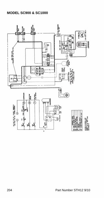
204 Part Number STH12 9/10
MODEL SC900 & SC1000

Part Number STH12 9/10 205
MODEL SC1000 (230 VAC)
Component Legend
L1 Line 1
L2 Neutral
M Motor
MS Contactor
PS Pressure Switch
IBC Ice Bank Control
Agitator Motor
CompressorIBC
L1 L2
M1
SW1
O/L
Fan
Start
M2120 Volt, 60 Hz, 1 Phase Domestic230 Volt, 50 Hz, 1 Phase Export
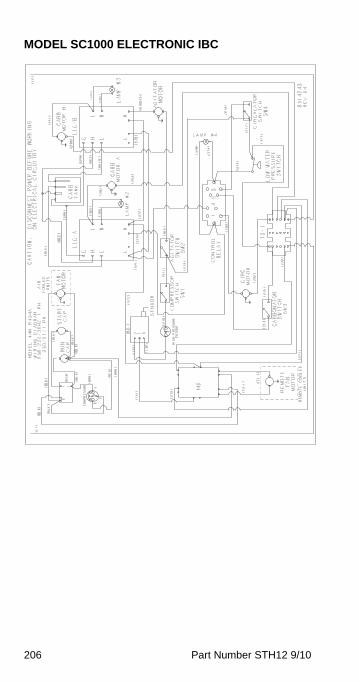
206 Part Number STH12 9/10
MODEL SC1000 ELECTRONIC IBC
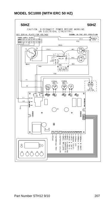
Part Number STH12 9/10 207
MODEL SC1000 (WITH ERC 50 HZ)
50HZ 50HZ
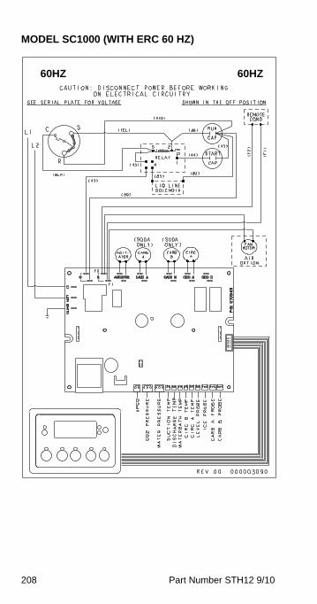
208 Part Number STH12 9/10
MODEL SC1000 (WITH ERC 60 HZ)
60HZ 60HZ
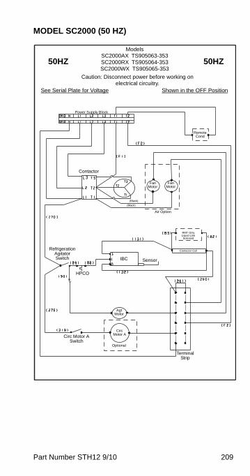
Part Number STH12 9/10 209
MODEL SC2000 (50 HZ)
50HZ 50HZ
ModelsSC2000AX TS905063-353SC2000RX TS905064-353SC2000WX TS905065-353
Caution: Disconnect power before working on electrical circuitry.
See Serial Plate for Voltage Shown in the OFF Position
Power Supply Block
Remote Cond
(Black)
(Black)
Contactor
Air Option
Fan Motor
Refrigeration Agitator Switch
Terminal Strip
IBC
Circ Motor ACirc Motor A
Switch
HPCO
Optional
Fan Motor
Sensor
Agt Motor
Contactor Coil
RMT Only Liquid Line Solenoid
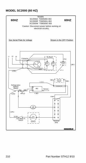
210 Part Number STH12 9/10
MODEL SC2000 (60 HZ)
60HZ 60HZModels
SC2000A TS905060-363SC2000R TS905061-363SC2000W TS905062-363
Caution: Disconnect power before working on electrical circuitry.
See Serial Plate for Voltage Shown in the OFF Position
Remote Cond
(Black)(Black)
ContactorAir Option
Fan Motor
Refrigeration Agitator Switch
Terminal Strip
IBC
Circ Motor ACirc Motor A
Switch
HPCO
Optional
Fan Motor
Sensor
Agt Motor
Contactor Coil
RMT Only Liquid Line Solenoid

Part Number STH12 9/10 211
WIRING DIAGRAM FRONT DRAW TOWER
Grn/Yel
Re
d
BlkWa
ter
Sw
itch
Key
Boa
rd
Sod
a S
witc
h
C o n t r o l
OF
F-O
N
Sw
itch
Sp
lice
Blk
Brn
Red
Org
Ye
lG
rnB
luV
ioG
ryW
ht
BlkB
lkW
ht
BlkBrnRedOrgYelGrnBluVioGryWht
Blk
WhtWhtRedBlk
Red
Blu
Wht
Blk
Wht
Blk
Wht
Blk
Wht
Blk
Red
Blu
Wht
Wht
Red
Blk
Grn
/Ye
l Blk
Blk
Blk Blk
Blk
Grn
/Ye
lWhtBlk
WhtBlk24
VA
C
Wht
Wht
(Optional use) CO2 Light
Blk
Red
Whi
teW
hiteLD
1LD
2LD
3LD
4LD
5L
D6
J20
J15
J16
J17
WS
WS
WS
WS
WS
WS
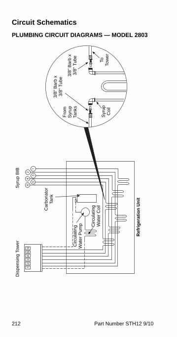
212 Part Number STH12 9/10
Circuit Schematics
PLUMBING CIRCUIT DIAGRAMS — MODEL 28031
23
45
6
1
2
3
4
5
6
3/8
" B
arb
x
3/8
" T
ub
e
Dis
pen
sin
g T
ow
er
Syr
up
BIB
Ca
rbon
ato
r Ta
nk
Cir
cula
ting
W
ate
r C
oil
Circ
ula
ting
W
ate
r P
ump
Ref
rig
era
tio
n U
nit
Syr
up
C
oil
To
Tow
er
3/8"
Ba
rb x
3
/8"
Tu
be
Fro
m
Syr
up
Ta
nks

Part Number STH12 9/10 213
PLUMBING CIRCUIT DIAGRAMS — MODEL 11M ROOT BEER
Single Tower Plumbing
Installation Kit(020001441)
020001403
00861302Pressurized
Filtered Water Supply
Circ Pump
Carb Tank
Primary Carb Pump
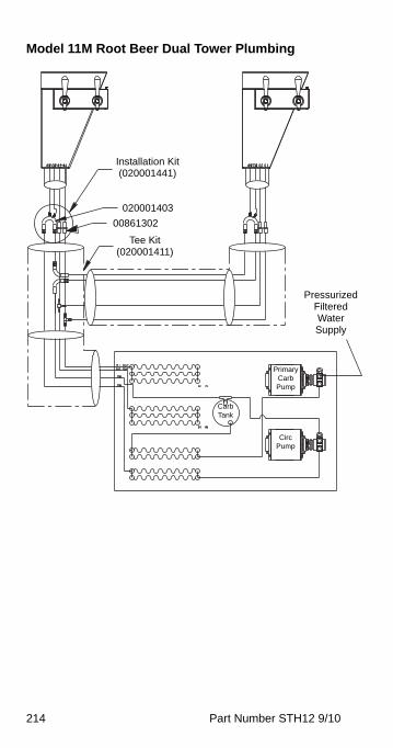
214 Part Number STH12 9/10
Model 11M Root Beer Dual Tower Plumbing
Installation Kit(020001441)
020001403
00861302
Pressurized Filtered Water Supply
Primary Carb Pump
Circ Pump
Carb Tank
Tee Kit(020001411)
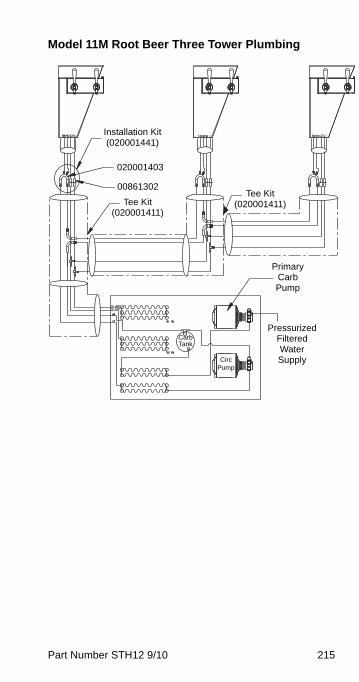
Part Number STH12 9/10 215
Model 11M Root Beer Three Tower Plumbing
Installation Kit(020001441)
020001403
00861302
Pressurized Filtered Water Supply
Primary Carb Pump
Circ Pump
Carb Tank
Tee Kit(020001411)
Tee Kit(020001411)
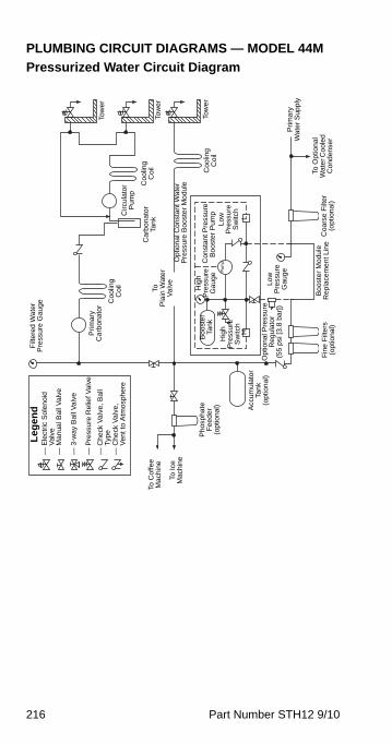
216 Part Number STH12 9/10
PLUMBING CIRCUIT DIAGRAMS — MODEL 44M
Pressurized Water Circuit Diagram
To C
offe
e M
achi
ne
To Ic
e M
achi
ne
Pho
spha
te
Fee
der
(opt
iona
l) Acc
umul
ato
r Ta
nk(o
ptio
nal
)
To
Pla
in W
ater
V
alve
Filt
ere
d W
ate
r P
ress
ure
Gau
ge
Prim
ary
Ca
rbon
ato
r
Ca
rbon
ato
rTa
nk
Co
olin
g C
oil
Circ
ulat
or
Pum
p
Tow
er
Tow
er
Opt
iona
l Co
nsta
nt W
ate
r P
ress
ure
Boo
ster
Mo
dule
Boo
ste
r Ta
nk
Hig
h P
ress
ure
Sw
itch
HL
Hig
h P
ress
ure
G
auge
Low
P
ress
ure
Sw
itch
Con
stan
t Pre
ssur
e
Bo
oste
r P
ump
Pu
mp
Opt
iona
l Pre
ssur
e R
egu
lato
r (5
5 ps
i [3
.8 b
ar]
)Lo
w
Pre
ssu
re
Gau
ge
Fin
e F
ilte
rs
(opt
iona
l)C
oars
e F
ilter
(o
ptio
nal)
To O
ptio
nal
Wat
er C
oole
d C
ond
ense
r
Prim
ary
W
ate
r S
upp
ly
Bo
oste
r M
odu
le
Rep
lace
me
nt L
ine
— E
lect
ric S
ole
noi
d
— V
alve
— M
anua
l Bal
l Val
ve
— 3
-way
Bal
l Val
ve
— P
ress
ure
Rel
ief V
alve
— C
hec
k V
alv
e, B
all
— T
ype
— C
hec
k V
alv
e,
— V
ent t
o A
tmos
pher
e
Coo
ling
Coi
l
Le
ge
nd
Tow
erC
ool
ing
Coi
l

Part Number STH12 9/10 217
Pre-mix Plumbing — Six Valve Towers with Connection at Center Island
NOTE: Other plumbing configurations are possible. Check tower installation manual before making connections.
6 12345
6 12345
6 12345
6 5 4 3 2 1
6A
5A
4A
3A
2A
1W
Single Tower System
Syrup Cooling Coils
Syrup Filters(#2 through #11
optional)
Syrup Tanks
Drive-thru or Center Island Tower
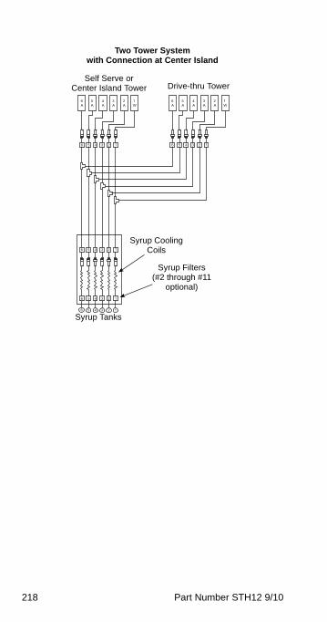
218 Part Number STH12 9/10
6 12345
6 12345
6 12345
6 5 4 3 2 1
6A
5A
4A
3A
2A
1W
6 12345
6A
5A
4A
3A
2A
1W
Two Tower Systemwith Connection at Center Island
Self Serve or Center Island Tower Drive-thru Tower
Syrup Tanks
Syrup Cooling Coils
Syrup Filters(#2 through #11
optional)
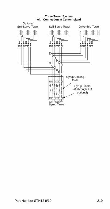
Part Number STH12 9/10 219
6 12345
6 12345
6 12345
6 5 4 3 2 1
6A
5A
4A
3A
2A
1W
6 12345
6A
5A
4A
3A
2A
1W
6 12345
6A
5A
4A
3A
2A
1W
Three Tower Systemwith Connection at Center Island
Self Serve Tower Drive-thru TowerOptional
Self Serve Tower
Syrup Tanks
Syrup Cooling Coils
Syrup Filters(#2 through #11
optional)
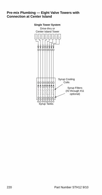
220 Part Number STH12 9/10
Pre-mix Plumbing — Eight Valve Towers with Connection at Center Island
6 5 4 3 2 1
6A
5A
4A
3A
2A
1W
7
7A
8
8A
6 123458 7
6 123458 7
6 123458 7
Single Tower System
Syrup Cooling Coils
Syrup Filters(#2 through #11
optional)
Syrup Tanks
Drive-thru or Center Island Tower

Part Number STH12 9/10 221
6 5 4 3 2 178
6A
5A
4A
3A
2A
1W
7A
8A
6 123458 7
6 123458 7
6 123458 7
6A
5A
4A
3A
2A
1W
7A
8A
6 1234578
Two Tower Systemwith Connection at Center Island
Self Serve or Center Island Tower Drive-thru Tower
Syrup Tanks
Syrup Cooling Coils
Syrup Filters(#2 through #11
optional)
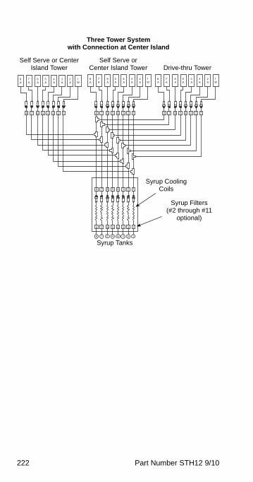
222 Part Number STH12 9/10
6 5 4 3 2 178
6A
5A
4A
3A
2A
1W
7A
8A
6 123458 7
6 123458 7
6 123458 7
6A
5A
4A
3A
2A
1W
7A
8A
6 1234578
6A
5A
4A
3A
2A
1W
7A
8A
6 1234578
Three Tower Systemwith Connection at Center Island
Self Serve or Center Island Tower Drive-thru Tower
Self Serve or Center Island Tower
Syrup Tanks
Syrup Cooling Coils
Syrup Filters(#2 through #11
optional)
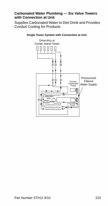
Part Number STH12 9/10 223
Carbonated Water Plumbing — Six Valve Towers with Connection at Unit
Supplies Carbonated Water to Diet Drink and Provides Conduit Cooling for Products
6A
5A
4A
3A
2A
1W
W98
W98
Single Tower System with Connection at Unit
Pressurized Filtered
Water Supply
Drive-thru or Center Island Tower
Primary Carbonator
Pump
Circulator Pump
Water Feeder
Carbonator Tank
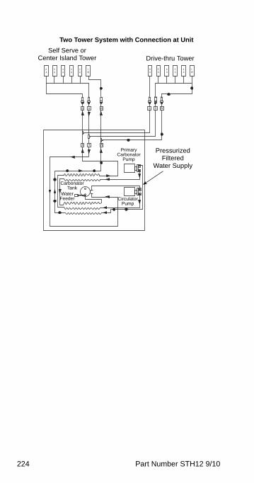
224 Part Number STH12 9/10
6A
5A
4A
3A
2A
1W
W98
W98
6A
5A
4A
3A
2A
1W
W98
Two Tower System with Connection at Unit
Self Serve or Center Island Tower Drive-thru Tower
Pressurized Filtered
Water Supply
Primary Carbonator
Pump
Circulator Pump
Water Feeder
Carbonator Tank
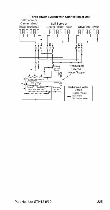
Part Number STH12 9/10 225
6A
5A
4A
3A
2A
1W
8
98
6A
5A
4A
3A
2A
1W
W9 8 89 9W
W
W
6A
5A
4A
3A
2A
1W
Three Tower System with Connection at Unit
Self Serve or Center Island Tower Drive-thru Tower
Self Serve or Center Island
Tower (optional)
Pressurized Filtered
Water Supply
Primary Carbonator
Pump
Circulator Pump
Water Feeder
Carbonator Tank
Carbonated Water Circuit
Legend (Water)
Plain WaterCarbonated Water
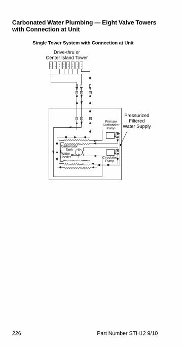
226 Part Number STH12 9/10
Carbonated Water Plumbing — Eight Valve Towers with Connection at Unit
6A
5A
4A
3A
2A
1W
W98
W98
7A
8A
Single Tower System with Connection at Unit
Pressurized Filtered
Water Supply
Drive-thru or Center Island Tower
Primary Carbonator
Pump
Circulator Pump
Water Feeder
Carbonator Tank
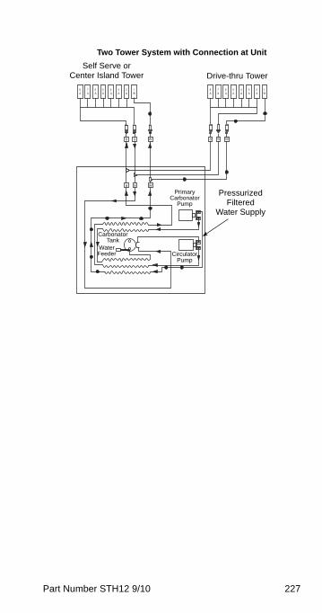
Part Number STH12 9/10 227
W98
W98
W98
6A
5A
4A
3A
2A
1W
7A
8A
6A
5A
4A
3A
2A
1W
7A
8A
Two Tower System with Connection at Unit
Self Serve or Center Island Tower Drive-thru Tower
Pressurized Filtered
Water Supply
Primary Carbonator
Pump
Circulator Pump
Water Feeder
Carbonator Tank
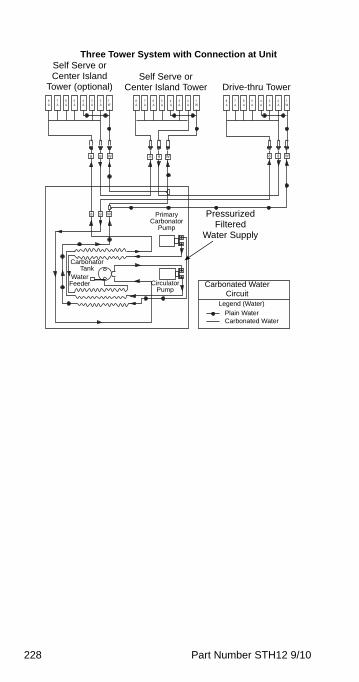
228 Part Number STH12 9/10
9 9
6A
5A
4A
3A
2A
1W
7A
8A
8 9 8W
6A
5A
4A
3A
2A
1W
7A
8A
6A
5A
4A
3A
2A
1W
7A
8A
W 8 W
8 9 W
Three Tower System with Connection at Unit
Self Serve or Center Island Tower Drive-thru Tower
Self Serve or Center Island
Tower (optional)
Pressurized Filtered
Water Supply
Primary Carbonator
Pump
Circulator Pump
Water Feeder
Carbonator Tank
Carbonated Water Circuit
Legend (Water)
Plain WaterCarbonated Water
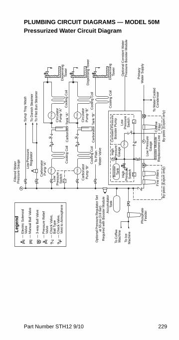
Part Number STH12 9/10 229
PLUMBING CIRCUIT DIAGRAMS — MODEL 50M
Pressurized Water Circuit Diagram
Dis
pens
ing
Tow
er
Dis
pens
ing
Tow
er
Dis
pens
ing
Tow
er
Syr
up T
ray
Was
h
To D
anis
h S
team
erTo
File
t Bun
Ste
amer
Filt
ered
Wat
er
Pre
ssur
e G
auge
Low
Pre
ssur
e R
egul
ator
Car
bon
ator
P
ump
“A
”
Pum
p
Low
P
ress
ure
S
witc
hL C
arbo
nato
r P
ump
“B”
Pum
pP
um
p
Pum
p
Circ
ula
tor
Pu
mp
“A”
Circ
ula
tor
Pu
mp
“B”C
oolin
g C
oil
Ca
rbo
nato
r Ta
nk “
A”
Coo
ling
Coi
l
Coo
ling
Coi
lC
arbo
nato
r Ta
nk
“B”
Coo
ling
Coi
lTo
Pla
in
Wa
ter
Val
ve
Coo
ling
Coi
l
Op
tion
al C
onst
ant W
ater
P
ress
ure
Boo
ster
Mod
ule
Prim
ary
W
ate
r S
upp
ly
— E
lect
ric S
ole
noid
—
Va
lve
— M
anu
al B
all
Val
ve
— 3
-way
Ba
ll V
alve
— P
ress
ure
Rel
ief
— V
alv
e—
Che
ck V
alve
, —
Bal
l Typ
e—
Che
ck V
alve
, —
Ven
t to
Atm
osph
ere
Opt
iona
l Pre
ssu
re R
egul
ato
r S
et
at 5
5 ps
i (3.
8 b
ar)
Re
quire
d w
ith B
oos
ter
Mod
ule
To C
offe
e
Mac
hine
To I
ce
Mac
hin
e
Pho
spha
te
Fee
derAcc
um
ulat
or
Tank
Boo
ster
Ta
nk
Hig
h P
ress
ure
Sw
itch
H
Hig
h
Pre
ssu
re
Gau
ge
Con
stan
t Pre
ssur
e B
oost
er P
um
p
Low
P
ress
ure
Sw
itch
L
Low
Pre
ssur
e G
aug
eTo
Wa
ter C
oole
d
Co
nden
ser
By-
pass
(E
xpor
t on
ly)
Coa
rse
Filt
erB
oost
er M
odu
le
Rep
lace
men
t Li
neF
ine
Filt
ers
By-
pass
(E
xpor
t onl
y)
Pu
mp
Le
ge
nd
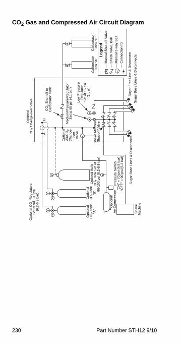
230 Part Number STH12 9/10
CO2 Gas and Compressed Air Circuit Diagram
Car
bon
ator
Ta
nk “
B”
Leg
end
— M
anu
al S
hut
-off
Val
ve
— C
heck
Val
ve, B
all
— M
anu
al 3
-way
Bal
l
— C
onne
ctio
n fo
r
Car
bona
tor
Tank
“A
”
Sug
ar F
ree
Line
& D
isco
nnec
t
Sug
ar
Bas
e Li
nes
& D
isco
nne
cts
Su
gar
Ba
se L
ine
s &
Dis
conn
ect
s
Op
tion
al
Air/
CO
2
Cha
nge-
ove
r V
alve
Opt
iona
l C
O2 C
han
ge-o
ver
Val
ve
AB
Opt
iona
l A
ir C
omp
ress
or
Opt
iona
l Bu
lkC
O2 T
ank
Set
at
90-
100
psi (
6.2
-6.9
bar
)
Op
tion
al
CO
2 T
ank
“A”
Opt
iona
l C
O2 T
ank
“B”
Pre
ssu
re S
witc
h“O
N”
= 7
0 ps
i (4.
8 b
ar)
“OF
F”
= 9
0 ps
i (6.
2 b
ar)
Sha
ke
Mac
hine
CO
2 S
hut-
off t
o C
arbo
nato
r Ta
nk
Med
ium
Pre
ssur
e R
egu
lato
r S
et a
t 60
psi
(4.
1 b
ar)
Low
Pre
ssur
e R
egul
ator
S
et a
t 15
psi
(1
bar
)
Sh
ake
Mac
hine
S
hut-
off V
alve
Opt
ion
al C
O2 R
egu
lato
rsS
et a
t 90
-100
psi
(6
.2-6
.9 b
ar)
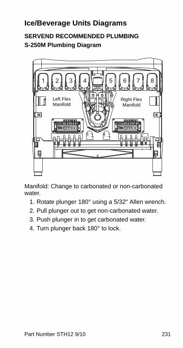
Part Number STH12 9/10 231
Ice/Beverage Units Diagrams
SERVEND RECOMMENDED PLUMBING
S-250M Plumbing Diagram
Manifold: Change to carbonated or non-carbonated water.
1. Rotate plunger 180° using a 5/32" Allen wrench.
2. Pull plunger out to get non-carbonated water.
3. Push plunger in to get carbonated water.
4. Turn plunger back 180° to lock.
1 2 3 4 5 6 7 8
Left Flex Manifold
Right Flex Manifold
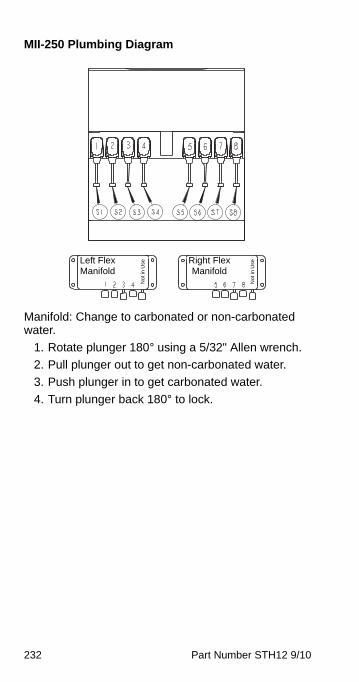
232 Part Number STH12 9/10
MII-250 Plumbing Diagram
Manifold: Change to carbonated or non-carbonated water.
1. Rotate plunger 180° using a 5/32" Allen wrench.
2. Pull plunger out to get non-carbonated water.
3. Push plunger in to get carbonated water.
4. Turn plunger back 180° to lock.
Left Flex Manifold
Right Flex Manifold
No
t in
Use
No
t in
Use
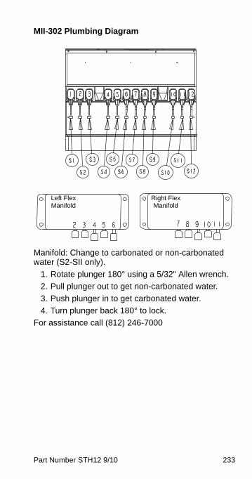
Part Number STH12 9/10 233
MII-302 Plumbing Diagram
Manifold: Change to carbonated or non-carbonated water (S2-SII only).
1. Rotate plunger 180° using a 5/32" Allen wrench.
2. Pull plunger out to get non-carbonated water.
3. Push plunger in to get carbonated water.
4. Turn plunger back 180° to lock.
For assistance call (812) 246-7000
Left Flex Manifold
Right Flex Manifold
234 Part Number STH12 9/10
This Page Intentionally Left Blank


Manitowoc Foodservice2100 Future Drive
Sellersburg, IN 47172, USAPh: 812-246-7000 Fax: 812-246-7024
Visit us online at: www.manitowocfsg.com
© 2010 ManitowocPart Number STH12 9/10