Embed Size (px)
Citation preview

Soft material modeling for robotic task formulation and controlin the muscle separation process
Essahbi Nabil n, Bouzgarrou Belhassen-Chedli, Gogu GrigorePascal Institute, UMR 6602 CNRS/UBP/IFMA, BP10448, F-63000 Clermont-Ferrand, France
a r t i c l e i n f o
Article history:Received 17 January 2014Received in revised form5 August 2014Accepted 11 September 2014
Keywords:Robotized anatomical cuttingSoft material dynamical modelingDynamic trajectory generation
a b s t r a c t
This paper introduces a global approach for the muscle separation process in the meat industry by usinga multi-arm robotic system. Process control is based on both physical modeling of soft material andvision perception. Mechanical models appropriate for real-time applications are examined andcompared through simulation results. In order to take into account material anisotropy, a newformulation based on mass-spring discretization, is proposed. While geometrical model constructionuses MRI techniques, physical parameters are determined by the use of rheological tests. The cuttingmodel for muscle separation is therefore considered through three approaches based on knife position,pull-off strength and experimental cutting forces. In order to generate robotic cutting tasks, a newalgorithm using the curvature estimation of a 3D surface mesh is introduced. This enables the cutting-tool path generation and updating.
& 2014 Elsevier Ltd. All rights reserved.
1. Introduction
In order to improve the safety and health conditions of work-ers, but also to find alternative solutions to counter increasingproduction costs due to labor shortages, mechanization and robot-ization are of increasing interest to companies in the meat sector.Robotic solutions should therefore enable companies to improvetheir profitability and competitiveness in an increasingly globa-lized market [1].
Nowadays, robots are expected to accomplish increasinglycomplex tasks. Various sensors can be used to achieve enhancedperception of the external environment. This is the case of image-based sensors which have become the focus of considerableinterest in recent years. Using such sensors, dynamical perceptionand a complete description of the surrounding scene are achievedbut this involves not straightforward robotic integration tasks thatmay be considered. The robotic system can see, interpret and thendefine the different tasks at hand. This is considered as the startingpoint for a fully automated process. In addition to the perceptionsystem, several numerical models may be integrated into theprocess. This contributes to defining the robotic cell commands,especially when dynamically complex tasks are needed in manip-ulating objects that evolve over time. One particular case is when
soft materials are dynamically manipulated: in this case, theassociation of physical modeling and vision perception may be asolution for defining automated dynamical robotic tasks.
The dynamical modeling of soft materials gives estimations oftheir future shape and internal state, while the active perceptionsystem provides feedback on their current surface shape as well asfeatures of the whole work environment. In this way, complexdynamic tasks can be treated within the ARMS ANR project, whoseobjective is to define a multi-arm robotic cell for muscle separa-tion in the meat industry. The manipulation of soft materials usinga robotic cell remains a complex task at multiple levels.
2. A multi-arm robotic cell for muscle separation
The global objective of the ANR project ARMS is to study therobotization of deboning and muscle separation in meat cuttingand transformation processes applied to beef rounds. One specifictask is the separation of the round and shank of beef muscles. It isnecessary to observe carefully and examine all the tasks per-formed by the butcher in order to adapt and predefine the overallarchitecture of the robotic cell as well as the location of eachrobotic arm. This operation consists in carefully cutting theaponeurosis (tissue separating the two muscles) over a length ofabout 50 cm using small incisions along the surface separatingthe two muscles (Fig. 1).
For each specific task, it is necessary to adapt the cuttingmotions and equip each robot armwith specific tools. By analyzinga human operator’s movements, four main identified mechanical
Contents lists available at ScienceDirect
journal homepage: www.elsevier.com/locate/rcim
Robotics and Computer-Integrated Manufacturing
http://dx.doi.org/10.1016/j.rcim.2014.09.0030736-5845/& 2014 Elsevier Ltd. All rights reserved.
n Corresponding author. Tel.: þ33 6 25 8766 35.E-mail addresses: [email protected] (E. Nabil),
[email protected] (B. Belhassen-Chedli),[email protected] (G. Grigore).
Robotics and Computer-Integrated Manufacturing 32 (2015) 37–53

actions, achieved simultaneously, have been identified i.e. hand-ling, pulling, pushing and/or cutting. These actions can be appliedto three different types of materials: rigid (bone), rigid/articulated(knee joint of the thigh) and soft material (meat/muscles) (Fig. 2).
The manipulation of a deformable object requires the control ofits location as well as its deformation. To determine the actualshape and displacement of a given handled object, an activeperception system tracks it by using structured light and 3Dvision. The robotic system also interacts with the physical modelpredicting muscle deformation in order to generate robotic com-mands of movement and cutting tasks (see Fig. 3 for the generalcontrol scheme). The global aim is to dynamically generate thetasks required for the robotized separation of muscles. Thisinvolves defining pulling tasks and cutting tasks while using theperception and feedback from arm sensors in order to predict inreal-time the behavior of muscles being manipulated. A primarytask in properly defining the process of muscle separation is todynamically generate a cutting guideline that accurately describesthe area where the arm equipped with the knife must act. Theestimation of the cutting guideline comes from the physical modelthrough the cutting modeling (see Section 3) as well as informa-tion from the vision module (see Section 4).
The vision module provides information necessary to updatethe physical model before each calculation loop. It also allows theadaptation of muscle dimensions (homotheties, distortions) andposition (rotations, translations) defined by a generic geometricmodel before starting the robotized tasks.
The robotic platform used for cutting/separating operations ofbovine muscles is composed of two Adept Viper robots S1700D.One is equipped with a knife for cutting and the other with agripper for pulling actions. In addition to these two robots, amuscle holding system is used as well as a KUKA LWR4þ lightweight robot for a camera moving along the scene (Fig. 4).
A multi-fingered robot hand can be associated to a robotic arm.This offers great advantages over traditional tools mounted to theend-effector of a robot arm. With a minimum of three contactpoints, they offer greater stability and mobility of the gripper [2].The problem is that up until today, the most highly developedrobotic hands are intended to fulfil the elementary tasks ofhandling rigid/soft objects with generally low applied efforts. Itis therefore crucial to better characterize muscle separationprocesses in order to establish an order of magnitude for therequired cutting effort (see Section 3 for details).
In the next section, we focus on the mechanical modeling andpresent selection criteria for soft material modeling. We alsodiscuss some appropriate models to the considered applicationand present our simulation results.
3. Real-time modeling of soft materials
The evolution of geometrical models in computer graphics hastraditionally focused on the representation of rigid objects. In 1986, aninitial free-form deformation method was presented. This deformedarbitrary objects by distorting the space in which they were contained[3]. A year later, Terzopoulos [4] incorporated physical propertiesdirectly in a graphical object for the first time, and coined the termof deformable models. Over the past fifteen years or so, many modelsthat are based on the concept of discrete elements have been proposedfor soft tissue. Nowadays, dynamic simulation of soft materials in real-time for virtual environments is an active area of research. Manymethods are used to perform simulation of deformable models such asthe lattice network model which consists of the approximation ofliving tissue by a lattice distribution [5]. Another way is to considerboundary element method based on continuum mechanics [6,7]. Thisapproach derives from finite element modeling and is also availablefor the fields of acoustics [8] and structural calculation [9]. Othermodels are available in the literature such as the volume distributionmodel [10] and Long element model [11] which considers tissues asincompressible objects mainly composed of liquid.
In the literature, several studies have addressed the comparison ofthese different modeling approaches by taking as criteria the comput-ing time, the visual realism, the adaptation to topology change, theimplementation complexity… [15,24–26]. However, the choice of themost appropriate method to the real-time interaction cannot bedefinitive: all depends on its application (e.g. boundary elementmethod is useful for the simulation of a fluid-filled body in which
Fig. 1. Separation steps of the round and shank of beef muscles.
Fig. 2. Task adaptation of muscle separation proposed in the ARMS project.Transcription of meat muscle separation tasks into robotized actions and systems.
E. Nabil et al. / Robotics and Computer-Integrated Manufacturing 32 (2015) 37–5338

only surface deformations is needed). In our case, the most appro-priate approaches, that seem to meet our requirements, are based ontensor-mass model [12–14] andmass-springmodel [15]. These modelsare the most prominent and reputable in the field of computergraphics for real-time modeling of soft materials. Thus, we proposeto compare them on the basis of simulation results in order to drawthe most appropriate one for an implementation within a control loopfor dynamic generation of robotic commands.
The model to be used in the considered application has to besufficiently representative of meat behavior and give significantinformation on object deformation as required by the dedicatedtracking systems. A mechanical model is derived from a numer-ical formulation (tensor-mass model, mass-spring model, etc.) and ageometric description which represents the distribution of the mate-rial to be modeled in space. The choice of the most appropriate modelis governed by two major criteria defined in [16]: realistic motion ofsoft tissue and real-time interactivity. The dynamic behavior of adeformable tissue must be correctly predicted. The deformable modelmust be able to give a correct representation of several types of organsas well as a realistic prediction of the deformations that will beincurred by the material. The immediate interactivity with the model-based control is a major constraint for a goodmodel. Hence, the modelmust be sufficiently reduced (compared to classical finite elementmodeling of material deformation) to be taken into account in realtime in the global control framework of the robotic cell.
The boundary conditions applied to such models are intendedto reproduce the interactions of the muscle with cutting andgrasping tools and holding system. In a dynamical simulation,these conditions can be constant or variable over time. In terms ofFE model, forces and pressures can be applied to some modelnodes or surfaces in order to simulate tractions or compressionsapplied by the grasper. Also, null displacements can be imposed tocertain nodes in contact with the plane of the supporting table.
3.1. Generic geometrical model construction
The size variability for the same type of muscle but from differentanimals implies that each muscle has to be characterized individu-ally. In addition, in the process under consideration, we have at leasttwo muscles to be separated with a common separation surface(aponeurosis). This surface is hidden and imperceptible by visiontechniques. Therefore, we propose the construction of 3D genericgeometric models of the processed muscles. These models can beadjusted to fit the actual geometry and predict the internal separa-tion surface. To this end, magnetic resonance imaging (MRI) techni-que is used [17] thus enabling the visualization of detailed internalstructures. The great advantage of this method is that it providesgood contrast between the different soft tissues of the body andprecise information about anatomical structure: shape of muscles,volumes, relative location to each other, and common surface
Fig. 3. Simplified control scheme and interaction among different modules of the robotic cell.
Fig. 4. Different views of the multi-arm robotic cell for muscle separation proposed in the ARMS project.
E. Nabil et al. / Robotics and Computer-Integrated Manufacturing 32 (2015) 37–53 39

between muscles. The result of an MRI scan is a succession of slices.As presented in Fig. 5, we can distinguish the borders of each musclein each cross section. This allows us to obtain the topology and buildthe volume of the entire scanned piece by three-dimensional (3D)image reconstruction techniques.
One of the ideas for adjusting the geometrical model is to scanthe surface of manipulated muscles using a perception systembefore operating the separation. This provides a points cloud in 3Dspace associated to the visible surface of the two muscles. Byconsidering the perceived points cloud as a reference data fordescribing the actual shape of manipulated muscles, the genericgeometrical model must be fitted to this data by undergoinggeometric transformations throughout an optimization process.The optimization criterion to be minimized may be the distancebetween perceived points cloud and corresponding surface nodesissued from the generic geometrical model. To readjust the genericgeometrical model, a combination of rotations, translations, dis-tortions and scaling are applied thereto. These geometrical trans-formations require the identification of twelve parameters (threerotation angles, three translations and six scaling and distortionfactors).
3.2. Rheological parameter identification
Simulation results are closely related to the choice of modelparameters. Within the framework of the ARMS project, a studywas conducted [18] to identify the rheological parameters of meat.
Between cattle, we can observe a variability of the rheologicalcharacteristics of muscles (age, sex, race…). From this finding, it isnecessary to conduct a series of tests on several samples ofmuscles with the aim of ensuring a better representation of themechanical behavior of muscles. The objective is to characterizethe handled muscles based on compression tests (until rupture ofthe sample) and tensile tests (up to 80% deformation). This allowsidentifying different rheological properties involved in musclesmechanical models.
Tests have defined the evolution of constraints according to thedeformation (Fig. 6). Consequently, for each range of meat defor-mation, the elasticity modulus is defined. Tests were made onthree directions: the longitudinal direction, which is the directionof meat fibers, transversal tests and 451 tests. For each test, fivecubic samples of 10 mm side are used and a low strain rate (in theorder of 0:05%� s�1) is considered to minimize the viscous
effects. For each test, stress curves are averaged before parameteridentification. These tests are elaborated in collaboration withINRA1.
We notice that for tensile tests, it is difficult to use the conventionalclamping techniques to attach the ends of the samples. An alternativeto this problem is to use a cryogenic cell [27] whose principle is tofreeze the ends of the sample to be studied while the temperature atits center remains unchanged (Fig. 6).
3.3. Tensor-mass model (TMM)
The linear tensor-mass model was introduced by Cotin et al.[12] and extended by Picinbono et al. [13] to non-linear elasticitybased on a St Venant Kirchoff model (hyperelastic materials). Forboth linear and non-linear formulations, the elastic energy for anisotropic material is given by:
W ¼ λ2tr Eð Þ2þ m tr E2
� �ð1Þ
where λ and m are the Lamé coefficients characterizing thematerial stiffness.
In the linear case, trðEÞ and trðE2 Þ represent the principalinvariants of the linearized Green—St. Venant strain tensor (3�3symmetric matrix) which depends on the 3�3 gradient matrix ofthe displacement U.
E¼ 12
∇Uþ∇Ut� � ð2Þ
In the nonlinear case, E stands for the complete Green—St.Venant strain tensor:
E¼ 12
∇Uþ∇Utþ∇Ut∇U� � ð3Þ
This model is valid for large displacements, which means inparticular that it is invariant with respect to rotations. This propertyimproves the realism of the deformations and solves the problemsrelated to the shortcomings of linear elasticity, which is only valid forsmall displacements. By using solid tetrahedral mesh and lumpedmass approximation, the governing equations of motion relative to themesh nodes is based on Newton’s law (Eq. (4)) and depends on theinternal forces issued from the elastic energy W introduced in Eq. (1)
Mi � €UiþDi � _Uiþ∑jFinti ¼ Rext
i ð4Þ
where for each node i, Ui is the position vector, _Ui and €Ui are itsvelocity and acceleration, Mi is the lumped mass, Di is the dampingcoefficient, Rext
i is the total externally applied load vector (e.g. gravityor user applied forces) and ∑jF
inti is the total internal elastic force
exerted by neighboring tetrahedral j containing the node i.Other extensions of the TMM method have emerged in order to
better suit different mechanical behaviors of modeled materials.Within this framework, Schwartz [14] has developed a viscoelasticvariant of TMM. The new formulation retains the geometricnonlinearity in the elastic component of the Kelvin–Voigt model(Eq. (2)). The stress–strain relationship is dynamically modified byadding the correction terms of Lamé coefficients to the stiffnesstensor thus introducing physical non-linearity.
In Fig. 7, we consider the round and shank of beef model to beconstituted by 1110 nodes and 4084 elements and solve dynami-cal equations using an implicit Euler method. The more thenumber of elements is important the more computing time islong: a coarse mesh (o2000 nodes) is more suitable for real-timecomputing than a fine mesh. The current geometry was meshed in
Fig. 5. Round and shank of beef (a), corresponding MRI slice (b), geometrical modelcreation (c), mesh generation (d). 1 INRA: Institut National de la Recherche Agronomique—www.inra.fr
E. Nabil et al. / Robotics and Computer-Integrated Manufacturing 32 (2015) 37–5340

ANSYSs from a CATIAs CAD model (geometrical model). Arrowsindicate the direction of the applied forces.
Computing time for the linear variant of TMM is about0:141 ms=iteration=node using SOFAs and a CPU implementa-tion on an Intels Core™ 2 Duo 3 GHz CPU, 4 GB RAM which issuitable for real-time modeling.
We note that computing time has been improved by a factor of� 3 compared to the MATLABs implementation (computingtime¼0:43 ms=iteration=node on the same machine).
3.4. Mass-spring model (MSM)
Mass-springmodels [15] are based onmeshes composed of springs(or spring-damper elements) and discrete mass points. In general, they
define a series of mass-free springs that are distributed over thesurface and/or volume of a modeled object and arewelded in points ornodes to which a discrete mass is attributed.
In our case, generation of spring elements is based on volu-metric tetrahedral meshes. These have the advantage of welldescribing objects with complex geometries. Furthermore, in thegeneral case of a mass-spring model, distributing the springsaccording to random edges directions improves the isotropy ofthe mechanical behavior of the model. Similarly, a hexahedralmesh could promote orthotropic mechanical behavior.
In a dynamical system, Newton’s second law governs themotion of each point mass in the lattice:
Mi � _UiþDi � _Uiþ∑jFinti;j ¼ Rext
i ð5Þ
Fig. 7. Model deformations using linear tensor-mass model: (a): visual model of initial state, (b): tetrahedral mesh elements of deformed shape (c): visual model ofdeformed shape.
Fig. 6. Tensile tests for a round of beef (a) a wooden support for sample’s ends freezing, (b) freezing in liquid nitrogen, (c) failure of the test piece, (d) stress evolution baseddeformations.
E. Nabil et al. / Robotics and Computer-Integrated Manufacturing 32 (2015) 37–53 41

All variables remain the same as for the tensor-mass model(Eq. (4)) except ∑jF
inti;j which now defines the sum along neigh-
boring nodes j of internal forces applied by neighboring springsassociated to nodes i and j. Generally, the internal force is theviscoelastic response of the spring connectors and is given by:
Finti;j ¼ � K �Δdþγ � _d� �
� Pij ð6Þ
where K is the coefficient of rigidity of a spring connector,γ is itsdamping coefficient, Δd and _d are the relative variation ofdistance and speed between the two connected nodes and Pij isthe unit vector joining these two nodes.
In Fig. 8, successive deformations were applied to the round ofbeef model. Arrows show the direction of applied forces whileother vertexes on the left are fixed. Springs and dampers arearranged along a tetrahedral mesh including 229 vertexes and 763elements. The current model was meshed in ANSYSs from aCATIAs model (geometrical model) whereas resolutions are com-puted under Matlabs. On the left, the initial state of the model ispresented, on the right side, the final state. The equation of motionis solved using an explicit 4th degree Runge–Kutta scheme.
The damping coefficient must be determined experimentally.However, we use, in this article, a default value so as to minimizethe vibration effects (fast convergence to equilibrium state andhave the most visually realistic meat behavior). At low speed ofdeformations corresponding to the process execution, this coeffi-cient weekly affects dynamic behavior.
Using an Intels Core™ 2 Duo 3 GHz CPU, 4 GB RAM, computingtime is about 0:502 ms=iteration=node for a MATLABs
implementation, however, it is about 0:11 ms=iteration=nodefor a SOFAs implementation.
3.5. A new formula for introducing anisotropy in mass-spring models
In meat modeling, it is necessary to take into consideration theanisotropy in soft material models. In fact, meat can be considered as atransversally isotropic material. The direction of anisotropy is definedby the fiber directions forming the meat. This allows us to have morerealistic results but, at the same time, must not penalize the modelperformance in terms of computation time. This also requires real-time interaction between the physical model and data from the visionmodule in order to define the direction of anisotropy of the musclesfor each time step; i.e. depending on muscle pose and orientation onthe worktable of the robotized cell. Anisotropy direction must describethe real fiber direction of the actual manipulated muscles.
In [19], D. Bourguignon and M. Cani have presented a newapproach introducing anisotropy in classical mass-spring modelsindependently from the 3D mesh. By considering directions ofinterest along which the material is the stiffest, the new forceexpression is computed at intersection points with volume ele-ments and then interpolated on the mass points for each timestep. The axial spring forces F1 and F2 between a pair of intersec-tion points 1 and 2 at positions x1 and x2 with velocities v1 and v2are computed according to this equation:
F1 ¼ � Ks ‖l21‖�rð ÞþKd
_l21 � l21‖l21‖
" #� l21
‖l21‖¼ �F2 ð7Þ
Fig. 9. Anisotropy direction (a) coinciding with muscle fibers (b).
Fig. 8. Deformations of a round of beef structure using a mass-spring model: initial state (a) and final state (b) with E¼ 0:03 MPa; ρ¼ 1500 kg m�3; Di ¼ 0:1 N s m�1.
E. Nabil et al. / Robotics and Computer-Integrated Manufacturing 32 (2015) 37–5342

where l21 ¼ x1�x2, r is the rest length _l21 ¼ v1�v2 is the timederivative of l21, Ks and Kd are respectively the stiffness anddamping constants.
The previous approach has the advantage of being independentfrom the geometry of the mesh. However, according to our experi-ments, computing time is increased compared to that of classicalmass-spring systems due to the various interpolations and intersectionpoints to be determined in the algorithm. Moreover, no validationresults were published as far as we know.
In [16], Chendeb has presented a new approach to identify springs’stiffnesses in a tetrahedral mesh governed by a mass-spring model.The formula expressing springs’ stiffnesses is related to the geometryand Young’s modulus of the corresponding material:
Ki;j ¼E �∑Ve
l2i;j��� ��� ð8Þ
where E is Young’s modulus, ∑Ve is the sum of volumes of tetra-hedrons having common edges li;j with the spring whose stiffness Ki;j
we are seeking to identify.This formula is very useful since it allows us to identify
stiffnesses according to element volumes and Young’s modulusinstead of allocating arbitrary values to mesh springs. Thismeans that the global stiffness is distributed to all edges inorder to obtain a more homogenous and realistic behavior ofthe model.
As we noted previously, in the case of meat manipulation, thematerial presents transversely isotropic properties (Fig. 9). Thismeans that both mechanical and physical properties changeaccording to a principal meat fiber direction i.e. the longitudinaldirection. In planes perpendicular to the longitudinal direction andcontaining radial and tangential directions, physical properties areinvariant.
Fig. 10. Compression (b) and tensile (c) tests and the respective evolution in Pa of stress according to displacements (d) starting from a cuboid model (a) associated with atransversally isotropic mass-spring model with El ¼ 0:25 MPa and Et ¼ Er ¼ 0:6 MPa.
E. Nabil et al. / Robotics and Computer-Integrated Manufacturing 32 (2015) 37–53 43

In this part, we propose and verify a new formula allowing bothstiffness identification and anisotropy introduction to the mass-spring models formed by tetrahedral meshes.
The equation previously proposed in Eq.(8) is extended to anis-otropic materials by imposing an elasticity modulus matrix E insteadof Young’s modulus. By considering a local coordinate systemðPi; a
!l; a!
t ; a!
rÞ, linked to a node Pi of the mesh, the expression ofE is given by:
E¼El 0 00 Et 00 0 Er
0B@
1CA
ðPi ; a!
l ; a!
t ; a!
r Þ
ð9Þ
The components of E are chosen so that the elasticity modules (El ; Etand Er) are allocated according to their corresponding directions.Their values are directly identified from the experimental tests ofmuscle characterization.
The stiffness Ki;j of the spring connecting vertices i and j can becalculated as follows:
Ki;j ¼1
li;j2‖EPiPj
li;j‖�∑
eVe ð10Þ
where li;j is the length of the spring ðPi; PjÞ and Ve is the volume ofeach element containing the edge ðPi; PjÞ.
The proposed approach is valid for the anisotropic general caseusing three different components of the elasticity modulus matrix. Itcan also be adapted to the case of transversally isotropic materials(fibers, biological tissues, meat…) using two equal components tocharacterize transversal and normal directions and a third differentcomponent to characterize the longitudinal direction.
Conversely, springs approaching perpendicularity to the aniso-tropy direction are affected by stiffness primarily derived from thetransverse and normal components of the elasticity modulusmatrix. This grants realistic behavior to the model according to
the directions different from those in the direction of anisotropy.Thus, the model responds differently depending on the loadingdirection and approaches more accurately the real case of trans-verse isotropic materials. This new formulation dissociates theintroduction of anisotropy from the mesh structure. However, themore refined the mesh, the more realistic the results will be. Inaddition, the stiffnesses of different springs are calculated at thebeginning of the algorithm (pre-computation step). In the simula-tion loop, we will no longer consider the anisotropy directionfor the calculation of internal forces applied to each node. Theexpression of internal forces remains invariant. In addition, theintroduction of anisotropy in this way does not affect the compu-tation time of the overall algorithm.
To check the behavior of a transversally isotropic material modeledusing this new approach, two types of tests can be performed in bothtensile and compression modes:
- Longitudinal tests in which the imposed displacement is carried bythe anisotropy direction (fiber direction).
- Transversal tests in which the imposed displacement is per-pendicular to the direction of anisotropy.
For each test, the evolution of stresses is calculated according tonode displacements and compared to the meat characterizationcurves (Fig. 10).
To further check the consistency of the new approach, bendingtests are applied to a cylindrical model perpendicularly to its directionof anisotropy (Fig. 11). In each test, the value of the longitudinalcomponent of the elasticity modulus matrix is modified while keepingthe same boundary conditions and the same transverse and normalcomponents ð0:003 MPaÞ. The algorithm is implemented in Matlabs
using a tetrahedral mesh composed of 95 nodes and 244 elements.Both upper and lower faces of the cylinder are fixed and a constantload of 40 N is applied to the center of the cylinder at each test.
Fig. 11. Effect of increasing the value of the longitudinal component of the elasticity modulus’s matrix on the behavior of a cylinder subjected to bending tests.
E. Nabil et al. / Robotics and Computer-Integrated Manufacturing 32 (2015) 37–5344

As expected, the model behaves adequately to increasingvalues of the longitudinal component of the elasticity modulusmatrix and becomes more rigid as they increase.
Furthermore, when choosing equal component values of theelasticity modulus matrix, the properties of a homogeneous iso-tropic material are reproduced. The application of this new formulaof spring stiffness determination to the isotropic case gives exactlythe same results as for the first method (Eq. (9)).
To further increase the realism of the model and adapt it to thecase of non-linear behavior, we propose to dynamically update itsrigidity parameters. To do this, the evolution of elastic moduli asfunction of a deformation criterion r in each main direction of thematerial is expressed by a 5th degree polynomial approximatingthe experimental rheological tests. In the case of simple unidirec-tional mechanical tests, we can consider the fraction: actuallength/initial length of the model to define the criterion r. In thegeneral case of multidirectional mechanical tests, it can be definedby the fraction: current volume/initial volume of the model.
The mathematical operations involved being simple, the com-putational time is slightly affected. The model is still valid for real-time applications while providing both non-linear and transver-sally isotropic mechanical behavior (Figs. 12 and 13).
The algorithm of the new non-linear transversally isotropicMSM is presented in Fig. 14.
3.6. Comparisons
In order to compare different methods of modeling, a numer-ical experiment has been considered. It consists in tensile andcompression tests applied to a simple geometric structure (paral-lelepiped shape) described by different versions of TMM and MSM(similarly to those outlined in Fig. 11).
The same boundary conditions as pervious tests are conservedwhile the displacements at the extremities are controlled. Thetotal mass of modeled structures, the elasticity moduli as well asthe choice of time intervals remain unchanged for all simulations.The tensile/compression forces required for the deformation ofeach model are calculated to check the mechanical behavior.Moreover, the computing time of dynamical loops is measuredfor each method by using a 4th order Runge–Kutta resolutionscheme.
In Table 1, a summary of simulation results is given in order tocompare the two previous methods as well as their implementa-tion in MATLABs.
The TMM requires a higher computing time than MSM: itsformulation is based on finite elements methods and thus oncontinuum mechanics. It offers visually realistic simulations. It isflexible regarding the choice of constitutive equations and involvesan easy setup. However, rigidity terms that are involved are so
Fig. 13. An example of the mechanical behavior of non-linear transversally isotropic MSM.
Fig. 12. Approximation of longitudinal and transversal elasticity moduli.
E. Nabil et al. / Robotics and Computer-Integrated Manufacturing 32 (2015) 37–53 45

complicated that they can only be computed in “off line” modeduring a pre-calculation step. All dynamic calculations assume thatsystem rigidity does not change during deformation, which iscontradictory to our intuition. Indeed the Lamé coefficients are usedto calculate rigidity information varying with the deformation of themodel. The same observation remains valid for Schwartz’s formula-tion where stiffness still depends on the initial state of the modeldespite the addition of correction terms. In addition, a dynamicalupdate of model rigidity is very expensive in terms of computationaltime and would be unsuitable for real time applications. A dynami-cally updating of all the terms of rigidity of the model from theexperimental tests of characterization of the modeled materialwould be very expensive for a real time application (computing
time is about about 4:29 s of pre-calculations for an hyperelasticTMM model associated with a mesh consisting of 65 nodes and 129elements using Matlabs on an Intels Core™ 2 Duo 3 GHz CPU, 4 GBRAM). This constitutes then a real restriction for obtaining therealistic mechanical behavior of the model.
On the other hand, the MSM is a simple model with a solidmathematical foundation and well-understood dynamics. Sincethe mass-spring network has a simple structure formed by masses,springs and dampers, many operations like large deformations andtopology modifications can be easily simulated. In addition, theintroduction of non-linear transversally isotropic MSM has sig-nificantly increased the realism, facilitated parameter identifica-tion and improved the mechanical behavior of the model.
Fig. 14. The non-linear transversally isotropic MSM algorithm.
E. Nabil et al. / Robotics and Computer-Integrated Manufacturing 32 (2015) 37–5346
More information about mass-spring and tensor-mass modelsand how to introduce anisotropy and volume conservation can befound in [20,21].
4. Anatomical cutting modeling
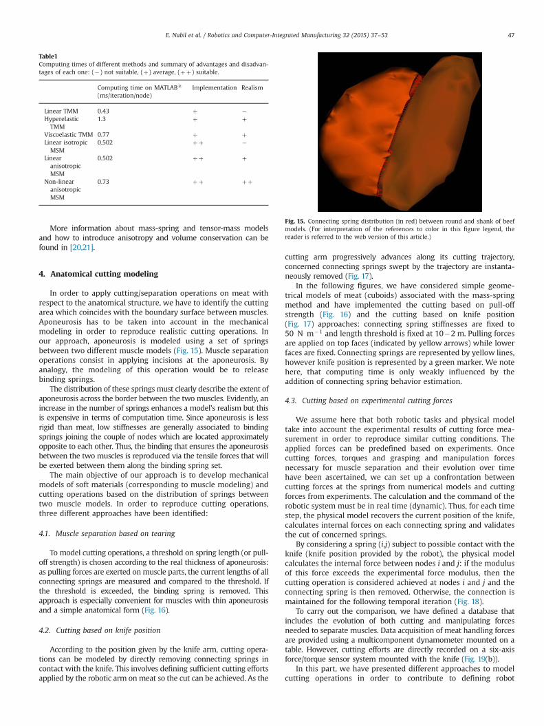
In order to apply cutting/separation operations on meat withrespect to the anatomical structure, we have to identify the cuttingarea which coincides with the boundary surface between muscles.Aponeurosis has to be taken into account in the mechanicalmodeling in order to reproduce realistic cutting operations. Inour approach, aponeurosis is modeled using a set of springsbetween two different muscle models (Fig. 15). Muscle separationoperations consist in applying incisions at the aponeurosis. Byanalogy, the modeling of this operation would be to releasebinding springs.
The distribution of these springs must clearly describe the extent ofaponeurosis across the border between the two muscles. Evidently, anincrease in the number of springs enhances a model’s realism but thisis expensive in terms of computation time. Since aponeurosis is lessrigid than meat, low stiffnesses are generally associated to bindingsprings joining the couple of nodes which are located approximatelyopposite to each other. Thus, the binding that ensures the aponeurosisbetween the two muscles is reproduced via the tensile forces that willbe exerted between them along the binding spring set.
The main objective of our approach is to develop mechanicalmodels of soft materials (corresponding to muscle modeling) andcutting operations based on the distribution of springs betweentwo muscle models. In order to reproduce cutting operations,three different approaches have been identified:
4.1. Muscle separation based on tearing
To model cutting operations, a threshold on spring length (or pull-off strength) is chosen according to the real thickness of aponeurosis:as pulling forces are exerted onmuscle parts, the current lengths of allconnecting springs are measured and compared to the threshold. Ifthe threshold is exceeded, the binding spring is removed. Thisapproach is especially convenient for muscles with thin aponeurosisand a simple anatomical form (Fig. 16).
4.2. Cutting based on knife position
According to the position given by the knife arm, cutting opera-tions can be modeled by directly removing connecting springs incontact with the knife. This involves defining sufficient cutting effortsapplied by the robotic arm on meat so the cut can be achieved. As the
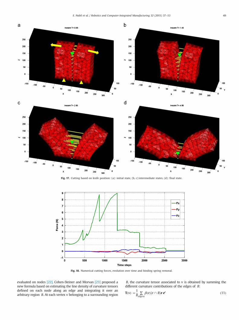
cutting arm progressively advances along its cutting trajectory,concerned connecting springs swept by the trajectory are instanta-neously removed (Fig. 17).
In the following figures, we have considered simple geome-trical models of meat (cuboids) associated with the mass-springmethod and have implemented the cutting based on pull-offstrength (Fig. 16) and the cutting based on knife position(Fig. 17) approaches: connecting spring stiffnesses are fixed to50 N m�1 and length threshold is fixed at 10�2 m. Pulling forcesare applied on top faces (indicated by yellow arrows) while lowerfaces are fixed. Connecting springs are represented by yellow lines,however knife position is represented by a green marker. We notehere, that computing time is only weakly influenced by theaddition of connecting spring behavior estimation.
4.3. Cutting based on experimental cutting forces
We assume here that both robotic tasks and physical modeltake into account the experimental results of cutting force mea-surement in order to reproduce similar cutting conditions. Theapplied forces can be predefined based on experiments. Oncecutting forces, torques and grasping and manipulation forcesnecessary for muscle separation and their evolution over timehave been ascertained, we can set up a confrontation betweencutting forces at the springs from numerical models and cuttingforces from experiments. The calculation and the command of therobotic system must be in real time (dynamic). Thus, for each timestep, the physical model recovers the current position of the knife,calculates internal forces on each connecting spring and validatesthe cut of concerned springs.
By considering a spring (i,j) subject to possible contact with theknife (knife position provided by the robot), the physical modelcalculates the internal force between nodes i and j: if the modulusof this force exceeds the experimental force modulus, then thecutting operation is considered achieved at nodes i and j and theconnecting spring is then removed. Otherwise, the connection ismaintained for the following temporal iteration (Fig. 18).
To carry out the comparison, we have defined a database thatincludes the evolution of both cutting and manipulating forcesneeded to separate muscles. Data acquisition of meat handling forcesare provided using a multicomponent dynamometer mounted on atable. However, cutting efforts are directly recorded on a six-axisforce/torque sensor system mounted with the knife (Fig. 19(b)).
In this part, we have presented different approaches to modelcutting operations in order to contribute to defining robot
Table1Computing times of different methods and summary of advantages and disadvan-tages of each one: (�) not suitable, (þ) average, (þþ) suitable.
Computing time on MATLABs
(ms/iteration/node)Implementation Realism
Linear TMM 0.43 þ �HyperelasticTMM
1.3 þ þ
Viscoelastic TMM 0.77 þ þLinear isotropicMSM
0.502 þþ �
LinearanisotropicMSM
0.502 þþ þ
Non-linearanisotropicMSM
0.73 þþ þþ
Fig. 15. Connecting spring distribution (in red) between round and shank of beefmodels. (For interpretation of the references to color in this figure legend, thereader is referred to the web version of this article.)
E. Nabil et al. / Robotics and Computer-Integrated Manufacturing 32 (2015) 37–53 47

commands necessary to perform muscle separation. Meat model-ing is complex and requires additional information to be able toattribute precise and accurate tasks to robotic arms. This addi-tional information is provided by the perception system accom-panying the robotic cell. The problem is treated in an “active” way,considering that the perception, modeling and action are inti-mately linked. In this type of methodology, the perception sys-tem and the physical model “serve” the action by generatingappropriate robotic commands, however, the action enriches themodeling part by providing feedback on arm displacements andapplied forces on the manipulated objects. This efficient collabora-tion between perception and the physical modeling modulesallows high level robotic tasks to be resolved.
In the following section, we define a new algorithm useful inidentifying cutting guidelines between different muscles. Thealgorithm is based on perception data provided by the activeperception system.
5. New algorithm based on curvature estimation and activeperception system for dynamic trajectory generation
The enhanced active perception system uses a combination ofstructured light and 3D cameras in order to extract real timeinformation (in addition to tracking deformable objects). It needsto be reactive to anticipate change and to control its ownconfiguration in order to perceive in the best possible way. Thissystem must be both efficient enough to embed the tracking of the
deformable model and fast enough to deal with real-time con-straints. 3D cameras and structured light allow muscle surface tobe captured as a 3D point cloud. In order to process this informa-tion, the set of cloud points is associated with a triangular surfacicmesh which incorporates the shape of the area perceived by thevision system. This area includes cutting paths that separate thetwo muscles (Fig. 20).
This helps the physical modeling module in its own recalibra-tion and improves its realistic motion. The generation of cuttingguidelines may be based on the results of the perception moduleand the physical model module. Once the cutting guideline isdefined, the task is transmitted to the robotic arm of the cell inorder to perform muscle separation.
In this section, we propose an efficient algorithm based oncurvature estimation in order to define the cutting trajectory of therobotic arm holding the knife. The algorithm can also be useful insimilar cases and allows us to identify concave and convex regionsof 3D surfaces with triangular meshes. After computing curvaturesof all mesh nodes, the algorithm estimates the cutting areabetween the muscles to be separated and defines the cuttingtrajectory for the robotic command.
5.1. 3D curvature tensor estimation
One way to compute curvature on surfacic meshes is to estimatecurvature tensors for each node and deduce the two principaldirection fields. However, this method proves to be not very naturalin the case of triangular meshes since surface curvature is only locally
Fig. 16. Muscle separation based on tearing: (a): initial state, (b, c):intermediate states, (d): final state.
E. Nabil et al. / Robotics and Computer-Integrated Manufacturing 32 (2015) 37–5348
evaluated on nodes [22]. Cohen-Steiner and Morvan [23] proposed anew formula based on estimating the line density of curvature tensorsdefined on each node along an edge and integrating it over anarbitrary region B. At each vertex v belonging to a surrounding region
B, the curvature tensor associated to v is obtained by summing thedifferent curvature contributions of the edges of B:
TðvÞ ¼ 1B
∑edgese
β eð Þ e \ B e et���� ð11Þ
Fig. 17. Cutting based on knife position: (a): initial state, (b, c):intermediate states, (d): final state.
Fig. 18. Numerical cutting forces, evolution over time and binding spring removal.
E. Nabil et al. / Robotics and Computer-Integrated Manufacturing 32 (2015) 37–53 49

where B is the surface area around v over which the tensor isestimated, β eð Þ is the signed angle between the normals to the twooriented triangles incident to edge e (positive if convex, negative ifconcave), je \ Bj is the length of e \ B (always between 0 and jej),and e is a unit vector in the same direction as e.
The normal at each vertex is estimated by the eigen vector ofTðvÞ multiplied by the eigen value of the minimum magnitude ofTðvÞ. Principal curvatures Cmin and Cmax are given by the twoother eigenvalues such that CminoCmax. The principal directionsof curvature are defined by γmin and γmax such that: the eigen-vector associated with the minimum eigenvalue is the maximumcurvature direction γmax, and vice versa for γmin.
Mean curvature and Gaussian curvature are defined as follows:
Cmean ¼ KminþKmax
2ð12Þ
CGauss ¼ Kmin � Kmax ð13Þ
For the implementation of the algorithm, mean curvature waschosen for identifying geometrical forms and cutting regions:clarity and contrast in cutting areas are much improved and muchhigher than those obtained by other methods (Fig. 21).
5.2. Cutting guideline implementation for dynamic trajectorygeneration
After characterizing the geometry of muscle surfaces by char-acterizing the curvature on each node of the surface, the algorithmuses a starting point P0, which is located on the boundaries of thesurface and a radius r chosen by the user. r is the radius around P0
in which potential nodes belonging to the cutting trajectory areidentified. Depending on the radius r, searches for iterations maybe refined (leading to several nodes) or made coarser (leading to alow number of nodes) (Fig. 22).
Around P0, the algorithm starts searching in the neighborhoodfor nodes with concave curvature properties and belonging to thesphere created by the radius r. This allows the selection of anumber of nodes all around P0. After that, the algorithm identifiesthe next node called P1 with lower height in the concave region.Once this point has been found, the search is reiterated around P1
and so on, until the entire concave area is covered (Fig. 23(a))using a set of points fP0; P1; P2;…; Png. The end of the algorithmtakes place when no new node verifies the search conditions.Thus, the set of selected nodes forms the cutting guideline. Usinginterpolation techniques (e.g. spline interpolation), a robotizedcutting task is derived to extend classical programming languages
Fig. 19. Separation of round and shank of beef: grasping and manipulation force evolution over time (a) using a multicomponent dynamometer mounted on a table (b) andcutting forces evolution over time (c) using a sensor mounted on the knife (b).
E. Nabil et al. / Robotics and Computer-Integrated Manufacturing 32 (2015) 37–5350

and is then transmitted to the robot. Muscle separation operationscan then be performed.
We note that computing time is about 0.378 s for a meshformed by1376 nodes and 2662 elements. The algorithm wasimplemented on MATLABs using an Intels Core™ i7-2760QMCPU 2.4 GHz, 8GB RAM
The point cloud is identified experimentally; it reproduces theactual geometry of the muscles. The cutting paths, thus generated,are visually satisfactory. We cannot consider here other validationcriteria because the challenge is to approach what is visuallycorrect by reference to trajectory generated by human operator(the butcher): the generated path is not necessarily unique orperfect.
A special alternative to this algorithm may be made throughthe choice of starting point P0. Depending on the location of thispoint, the algorithm can converge when P0 is located at the valleyor otherwise diverges. As part of the automation of the entire meatcutting process, one solution is to manually put a patch in thevalley separating the two muscles. Acquisition of the entire 3Dscene by the vision module is used to communicate the geometric
3D coordinates of the starting point. The dynamic trajectorygeneration algorithm can then be launched with respect to thereal time process criterion.
This algorithm as defined is particularly useful in this specificcase of muscle separation. Moreover, it can be just as effective in awide variety of applications. For example, it can be adapted to thesegmentation of triangular surfacic meshes. In seeking linesforming concave areas of a 3D surface, it is able to highlight thevarious regions (or surfacic patches) that form it and therefore tosegment the whole surface or object.
6. Conclusion
In this paper, a new multi-arm robotic system for muscleseparation in meat industry has been introduced. The processcontrol combines both physical modeling and vision perceptionand is intended for complex robotic tasks. Physical modelingallows the prediction of soft material behavior whereas visionperception enriches system observation by providing the actual
Fig. 21. Different curvature estimates of a triangular surfacic mesh derived from vision acquisition of round and shank of beef muscles.
Fig. 20. (a) Initial triangular surfacic mesh after camera acquisition, and triangular surfacic mesh generation (b).
E. Nabil et al. / Robotics and Computer-Integrated Manufacturing 32 (2015) 37–53 51

state of the manipulated object. In order to construct physicalmodels, certain criteria such as realistic motion and real-timeinteractivity were defined. The construction of the geometricalmodel using MRI techniques and rheological parameter identifica-tion were also presented.
Two mechanical models that fit our problem have been pre-sented: the mass-spring model and the tensor-mass model.Simulation results as well as a comparative study as to the realismof the models and computing times were presented. We also
proposed and tested a new way to fix the parameters of the mass-spring model whilst taking into account material anisotropy. Thenew approach sets the model in non-linear mechanical behaviormode which therefore increases the realism of the simulationsperformed.
Several cutting models have been proposed and simulated. Thecutting action according to knife position, muscle separation bytearing, and cutting based on experimental cutting forces havebeen simulated.
Fig. 22. Cutting guideline identification algorithm for dynamic trajectory generation.
Fig. 23. General diagram of cutting guideline identification algorithm (a) and implementation results (b).
E. Nabil et al. / Robotics and Computer-Integrated Manufacturing 32 (2015) 37–5352

Finally, a new algorithm based on vision perception and curvatureestimation of 3D surfacic meshes is introduced. This allows cuttingguideline estimation in order to generate robotic cutting tasks.
Acknowledgements
This work was funded by the ANR ARMS project and theEuropean project ECHOR-DEXDEB.
Experimental tests for muscle characterization, generic geome-trical model construction and the apprenticeship of manualcutting operations have been respectively elaborated in collabora-tion with INRA, CHU Clermont-Ferrand 2 and ADIV3.
References
[1] ARMS project ARPEGE program. ARMS project; 2010. ⟨http://arms.irccyn.ec-nantes.fr⟩/.
[2] Härtl H. Dextrous manipulation with multifingered robot hands includingrolling and slipping of the fingertips. Rob Auton Syst 1995;14(1):29–53.
[3] Sederberg TW, Parry SR. Free-form deformation of solid geometric models.(August). ACM Siggraph Comput Graphics 1986;20(4):151–60 (ACM).
[4] Terzopoulos D, Platt J, Barr A, Fleischer K. Elastically deformable models.(August). ACM Siggraph Comput Graphics 1987;21(4):205–14 (ACM).
[5] Lyvan, K.Etude de matériaux élastiques définis par des barres. Application à lasimulation en chirurgie endoscopique. (Doctoral dissertation, université PaulSabatier); 2003.
[6] James DL, Pai DK. ArtDefo: accurate real time deformable objects. In:Proceedings of the 26th annual conference on computer graphics andinteractive techniques. ACM Press/Addison-Wesley Publishing Co.; 1999;65–72.
[7] Meier U, Monserrat C, Parr NC, García FJ, Gil JA. (January). Real-time simulationof minimally-invasive surgery with cutting based on boundary elementmethods. In: Medical Image Computing and Computer-Assisted Intervention—MICCAI, 2001. Berlin Heidelberg: Springer; 2001; 1263–4.
[8] Kirkup S. The boundary element method in acoustics: a development inFortran (1). Stephen Kirkup; 1998.
[9] Wrobel LC, Aliabadi, MH. The boundary element method, Vol 1: applicationsin thermo-fluids and acoustics, Vol 2: applications in solids and structures;2002.
[10] Sundaraj K. Real-time dynamic simulation and 3D interaction of biologicaltissue application to medical simulators (Doctoral dissertation); 2004.
[11] Costa I.F. Balaniuk, R. (2001). LEM-An approach for real time physically basedsoft tissue simulation. In: Proceedings 2001 ICRA. IEEE international confer-ence on Robotics and automation, 2001.. (Vol. 3, pp. 2337–2343). IEEE.
[12] Cotin S, Delingette H, Ayache N. A hybrid elastic model for real-time cutting,deformations, and force feedback for surgery training and simulation. VisualComput 2000;16(8):437–52.
[13] Picinbono G, Delingette H, Ayache N. Non-linear anisotropic elasticity for real-time surgery simulation. Graph Models 2003;65(5):305–21.
[14] Schwartz JM. Calcul rapide de forces et de déformations mécaniques non-linéaires et visco-élastiques pour la simulation de chirurgie (Doctoral dis-sertation, Université Laval); 2003.
[15] Meier U, López O, Monserrat C, Juan MC, Alcaniz M. Real-time deformablemodels for surgery simulation: a survey. Comput Methods programs Biomed2005;77(3):183–97.
[16] Chendeb S. Chirurgie virtuelle: modélisation temps réel des tissus mous,interactions et système haptique dédié (Doctoral dissertation, École NationaleSupérieure des Mines de Paris); 2007.
[17] Bouzgarrou BC, Tumchou R, Minard S. Finite element modeling of a beefmus-cle. (‘Unpublished results’, InstitutFrançais de mécaniqueavancée); 2012.
[18] Bouzgarrou BC, Ducreux, JB. (2012) Characterization of mechanical interac-tions in cutting and separating muscles.(‘Unpublishedresults’, Institut Françaisde mécaniqueavancée).
[19] Bourguignon D, Cani MP. Controlling anisotropy in mass-spring systems. In:Computer animation and simulation, 2000. Vienna: Springer; 2000; 113–23.
[20] Essahbi N, Bouzgarrou BC, Gogu G. Soft material modeling for roboticmanipulation. In: Gogu G, Maniu I, Lovacs E-C, Fauroux J-C, Ciupe V, editors.Mechanisms, mechanical transmissions and robotics. Switzerland. ISBN: 978-3-03785-395-5. p. 184–93.
[21] Essahbi N, Bouzgarrou BC, Gogu G. Soft material modeling for muscleseparation process control and dynamic trajectory generation. In: Terze Z.ECCOMAS thematic conference. Multibody dynamics, Zagreb ; 2013, isbn:978-953-7738-21-1.
[22] Alliez P, Cohen-Steiner D, Devillers O, Lévy B, Desbrun M. Anisotropicpolygonal remeshing. ACM Trans Graphics (TOG) 2003;22(3):485–93 (ACM).
[23] Cohen-Steiner D. Morvan J.M. (2003, June). Restricted delaunay triangulationsand normal cycle. In: Proceedings of the nineteenth annual symposium oncomputational geometry (312-321).ACM.
[24] Nealen A, Müller M, Keiser R, Boxerman E, Carlson M. Physically baseddeformable models in computer graphics. Computer graphics forum2006;25(4):809–36 (Black well Publishing Ltd).
[25] Ghembaza MBK. Modélisation des déformations des tissus biologiques pour lasimulation réaliste et interactive en robotique chirurgicale mini-invasive.(Doctoral dissertation, Université paris XII Val de Marne); 2005.
[26] Paccini A. Développement d’un modèle éléments finis 3D appliqué à lasimulation d’opérations chirurgicales des tissus mous (Doctoral dissertation,École Nationale Supérieure des Mines de Paris); 2005.
[27] Lepetit J, Favier R, Grajales A, Skjervold PO. A simple cryogenic holder fortensile testing of soft biological tissues. J Biomech 2004;37(4):557–62.
2 CHU Clermont-Ferrand: Centre Hospitalier Universitaire de Clermont-Ferrand—www.chu-clermontferrand.fr
3 ADIV: Institut technique Agro-Industriel des filières viandes—www.adiv.fr
E. Nabil et al. / Robotics and Computer-Integrated Manufacturing 32 (2015) 37–53 53