Embed Size (px)
Citation preview
Soft fluidic rotary actuator with improved actuation properties
J. Fras1, Y. Noh2, H. Wurdemann3, K. Althoefer1
Abstract— The constantly increasing amount of machinesoperating in the vicinity of humans makes it necessary torethink the design approach for such machines to ensurethat they are safe when interacting with humans. Traditionalmechanisms are rigid and heavy and as such consideredunsuitable, even dangerous when a controlled physical contactwith humans is desired. A huge improvement in terms of safehuman-robot interaction has been achieved by a radically newapproach to robotics - soft material robotics. These new robotsare made of compliant materials that render them safe whencompared to the conventional rigid-link robots. This undeniableadvantage of compliance and softness is paired with a numberof drawbacks. One of them is that a complex and sophisticatedcontroller is required to move a soft robot into the desiredpositions or along a desired trajectory, especially with externalforces being present. In this paper we propose an improvedsoft fluidic rotary actuator composed of silicone rubber andfiber-based reinforcement. The actuator is cheap and easilymanufactured providing near linear actuation properties whencompared to pneumatic actuators presented elsewhere. Thepaper presents the actuator design, manufacturing processand a mathematical model of the actuator behavior as wellas an experimental validation of the model. Four differentactuator types are compared including a square-shaped andthree differently reinforced cylindrical actuators.
I. INTRODUCTION
A large range of actuators have been employed in variousareas such as robot hands, surgical robots, hybrid assistivelimb systems, and prosthetic limbs and hands. The traditionalapproach of designing mechanical systems is focused onmaking use of electrical actuators joined with transmissionmechanisms such as gears or linear translation systems totransmit high torque to mechanical joints or to convertrotational motion to translational motion - in such cases, theoverall system is heavy and bulky.
As the number of machines operating in the vicinity ofhumans is growing, the risk of potentially harmful human-machine interaction is increasing, and, hence, there is a needof redesign in robotics with safety being at the forefront ofconsiderations. Improving robotics safety is still an ongoingprocess also in the area of traditional actuator mechanics.With current advances in technology, actuators get smallerand lighter, sophisticated sensing is incorporated into theirstructure and new control strategies are being developed
1J. Fras and K. Althoefer are with the Centre of Advanced Robotics@ Queen Mary (ARQ), Faculty of Science and Engineering, Queen MaryUniversity of London, London E1 4NS, UK [email protected],[email protected]
2Y. Noh is with the Department of Informatics, King’s College London,London WC2R 2 LS, UK [email protected]
3H.A. Wurdemann is with the Department of Mechanical En-gineering, University College London, London WC1E 6BT, [email protected]
[1]. However, this approach is not perfect as accidents stillhappen, and the impact of a rigid device can still exceed asafety threshold.
The risk of injury is significantly decreased by a radi-cally new robotics approach, soft material robotics [2]–[4].Thanks to soft and compliant materials that these robots arecomposed of, a significantly safer interaction with humanscompared to conventional rigid-link robots can be achieved.However, the biggest soft robotics advantage, i.e. softnessand compliance, brings also a number of drawbacks. Oneof them is that actuation and control becomes very complexand demanding since the actuators and linkages are madeof soft and compliant materials. One of the most popularsoft actuators are flexible fluidic actuators (FFA). There aredifferent types of FFAs [5] that can be classified by theirbehavior e.g., actuators that contract along their primary axis,those that expand along their primary axis, those that twistalong their primary axis (rotating) [6], those that bend (alsorotation) [7]–[10], and those with complex motion behaviors[11], [12].
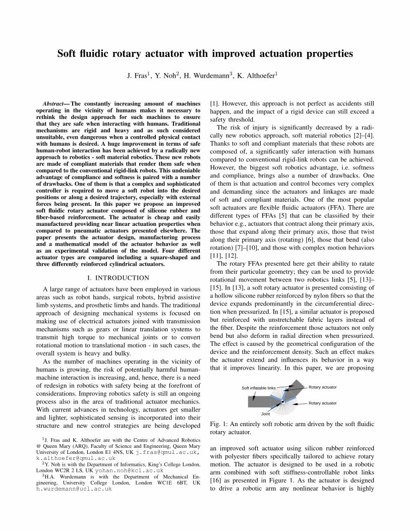
The rotary FFAs presented here get their ability to ratatefrom their particular geometry; they can be used to providerotational movement between two robotics links [5], [13]–[15]. In [13], a soft rotary actuator is presented consisting ofa hollow silicone rubber reinforced by nylon fibers so that thedevice expands predominantly in the circumferential direc-tion when pressurized. In [15], a similar actuator is proposedbut reinforced with unstretchable fabric layers instead ofthe fiber. Despite the reinforcement those actuators not onlybend but also deform in radial direction when pressurized.The effect is caused by the geometrical configuration of thedevice and the reinforcement density. Such an effect makesthe actuator extend and influences its behavior in a waythat it improves linearity. In this paper, we are proposing
Soft inflatable links
Joint
Rotary actuator
Rotary actuator
Fig. 1: An entirely soft robotic arm driven by the soft fluidicrotary actuator.
an improved soft actuator using silicon rubber reinforcedwith polyester fibers specifically tailored to achieve rotarymotion. The actuator is designed to be used in a roboticarm combined with soft stiffness-controllable robot links[16] as presented in Figure 1. As the actuator is designedto drive a robotic arm any nonlinear behavior is highly
undesired since that would require more complicate control.Any radial deformation or expansion of the actuator may bea problem too, as it makes the arm dimensions unstable andincreases the risk of self-collision or uncontrolled interactionwith the environment. The modified reinforcement strategyand circular cross-section shape solve the shortcomings ofconventional rotary actuators. The proposed design showsnot only highly linear characteristics, but also reduces theradial expansion observed in other designs.
II. MECHANICAL DESIGN
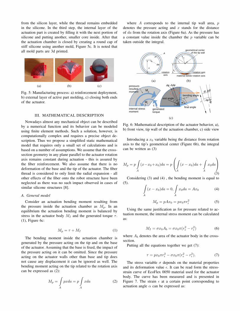
The actuator is composed of three main parts: an actuationchamber, a tip and a base. The actuation chamber is madeof soft silicone EcoFlex 0050 (Shore 00-50), while for thebase and the tip the relatively stiff silicone - SmoothSill 940(Shore 40 A)- has been used. The chosen materials allow theactuator to bend and prevent its both ends from deformation.The actuation chamber is reinforced with a polyester threadthat restrains its radial expansion. The application of thethread for such a purpose has been already extensivelyexamined and shows very good performance [17], [8]. Thethread is formed in a helix with an equally spaced pitchalong the actuator angular length. The intersection of all theplanes that the circular cross sections of the helix are locatedon defines the actuator rotation axis. The complete actuatorweighs around 20 grams. The actuator design is presentedin Figure 2.
tip
base
actuation part
reinforcement
connection
(a)
actuation chamber
stiff material
soft material
reinforcement
rotation axis
36mm
4mm
(b)
reinforcement
ri
rr
re 34m
m30m
m26m
m
(c)
Fig. 2: Single module design. a) side view, b) side cross-section, c) front cross-section.
A. Cross-section and reinforcement geometry
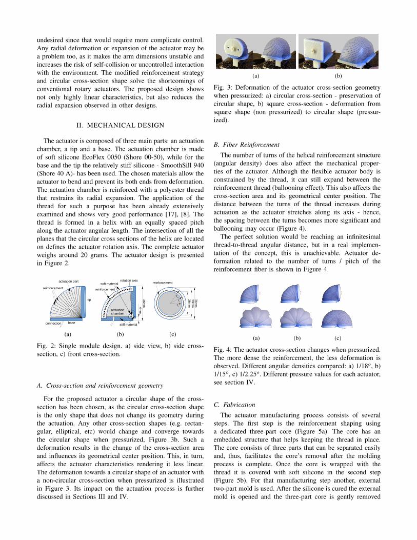
For the proposed actuator a circular shape of the cross-section has been chosen, as the circular cross-section shapeis the only shape that does not change its geometry duringthe actuation. Any other cross-section shapes (e.g. rectan-gular, elliptical, etc) would change and converge towardsthe circular shape when pressurized, Figure 3b. Such adeformation results in the change of the cross-section areaand influences its geometrical center position. This, in turn,affects the actuator characteristics rendering it less linear.The deformation towards a circular shape of an actuator witha non-circular cross-section when pressurized is illustratedin Figure 3. Its impact on the actuation process is furtherdiscussed in Sections III and IV.
(a) (b)
Fig. 3: Deformation of the actuator cross-section geometrywhen pressurized: a) circular cross-section - preservation ofcircular shape, b) square cross-section - deformation fromsquare shape (non pressurized) to circular shape (pressur-ized).
B. Fiber Reinforcement
The number of turns of the helical reinforcement structure(angular density) does also affect the mechanical proper-ties of the actuator. Although the flexible actuator body isconstrained by the thread, it can still expand between thereinforcement thread (ballooning effect). This also affects thecross-section area and its geometrical center position. Thedistance between the turns of the thread increases duringactuation as the actuator stretches along its axis - hence,the spacing between the turns becomes more significant andballooning may occur (Figure 4).
The perfect solution would be reaching an infinitesimalthread-to-thread angular distance, but in a real implemen-tation of the concept, this is unachievable. Actuator de-formation related to the number of turns / pitch of thereinforcement fiber is shown in Figure 4.
(a) (b) (c)
Fig. 4: The actuator cross-section changes when pressurized.The more dense the reinforcement, the less deformation isobserved. Different angular densities compared: a) 1/18o, b)1/15o, c) 1/2.25o. Different pressure values for each actuator,see section IV.
C. Fabrication
The actuator manufacturing process consists of severalsteps. The first step is the reinforcement shaping usinga dedicated three-part core (Figure 5a). The core has anembedded structure that helps keeping the thread in place.The core consists of three parts that can be separated easilyand, thus, facilitates the core’s removal after the moldingprocess is complete. Once the core is wrapped with thethread it is covered with soft silicone in the second step(Figure 5b). For that manufacturing step another, externaltwo-part mold is used. After the silicone is cured the externalmold is opened and the three-part core is gently removed
from the silicon layer, while the thread remains embeddedin the silicone. In the third step, the internal layer of theactuation part is created by filling it with the next portion ofsilicone and putting another, smaller core inside. After thatthe actuation chamber is closed by creating a round cap ofstiff silicone using another mold, Figure 5c. It is noted thatall mold parts are 3d printed.
(a) (b) (c)
Fig. 5: Manufacturing process: a) reinforcement deployment,b) external layer of active part molding, c) closing both endsof the actuator.
III. MATHEMATICAL DESCRIPTION
Nowadays almost any mechanical object can be describedby a numerical function and its behavior can be modeledusing finite element methods. Such a solution, however, iscomputationally complex and requires a precise object de-scription. Thus we propose a simplified static mathematicalmodel that requires only a small set of calculations and isbased on a number of assumptions. We assume that the cross-section geometry in any plane parallel to the actuator rotationaxis remains constant during actuation - this is assured bythe fiber reinforcement. We also assume that there is nodeformation of the base and the tip of the actuator. The fiberthread is considered to only limit the radial expansion - allother effects of the fiber onto the robot structure have beenneglected as there was no such impact observed in cases ofsimilar silicone structures [8].
A. General model
Consider an actuation bending moment resulting fromthe pressure inside the actuation chamber as Mp. In anequilibrium the actuation bending moment is balanced bystress in the actuator body MI and the generated torque τ .(1), Figure 6c:
Mp = τ +MI (1)
The bending moment inside the actuation chamber isgenerated by the pressure acting on the tip and on the baseof the actuator. Assuming that the base is fixed, the impact ofthe pressure acting on it can be omitted. Since the pressureacting on the actuator walls other than base and tip doesnot cause any displacement it can be ignored as well. Thebending moment acting on the tip related to the rotation axiscan be expressed as (2):
Mp =
∫A
pxda = p
∫A
xda (2)
where A corresponds to the internal tip wall area, pdenotes the pressure acting and x stands for the distanceof da from the rotation axis (Figure 6a). As the pressure hasa constant value inside the chamber the p variable can betaken outside the integral.
rotation axis
x
A
da
(a)
rotation axisx
0
geometrical center of the tip wall
ri
re
material below rotation axis
(b)
dl Δdl
rdφ
Δdφ
...
rest angle
final angleφ φ'
dφ Δdφ
r
bending angleα
Mp
MI
τ
pressure-resulted moment
internal stress moment
generated torque
(c)
Fig. 6: Mathematical description of the actuator behavior, a),b) front view, tip wall of the actuation chamber, c) side view
Introducing a x0 variable being the distance from rotationaxis to the tip’s geometrical center (Figure 6b), the integralcan be written as (3)
Mp = p
∫A
(x−x0+x0)da = p
∫A
(x− x0)da+
∫A
x0da
(3)
Considering (3) and (4) , the bending moment is equal to(5). ∫
A
(x− x0)da = 0,
∫A
x0da = Ax0 (4)
Mp = pAx0 = px0πr2i (5)
Using the same justification as for pressure related to ac-tuation moment, the internal stress moment can be calculatedas:
MI = σx0Ab = σx0π(r2e − r2i ) (6)
where Ab denotes the area of the actuator body in the cross-section.
Putting all the equations together we get (7):
τ = px0πr2i − σx0π(r2e − r2i ). (7)
The stress variable σ depends on the material propertiesand its deformation value ε. It can be read form the stress-strain curve of EcoFlex 0050 material used for the actuatorbody. The curve has been measured and is presented inFigure 7. The strain ε at a certain point corresponding toactuation angle α can be expressed as:
ε =∆dl
dl=r∆dϕ
rdϕ=ϕ′ − ϕ
ϕ=α
ϕ. (8)
where ϕ and ϕ′ stand for the actuator’s rest and activeangles, respectively (Figure 6c).
It is important to note that the strain does not dependon the r value and remains constant for the entire actuatorvolume (despite a small part of the flexible actuation chamberbelow the rotation axis that has been neglected due to itsrelatively small volume - marked in orange in Figure 6b.
With regards to the measured characteristics (7) can berewritten as:
τ(p, α) = px0πr2i − σ(ε(α))x0π(r2e − r2i ). (9)
For a constant angle α the torque is a linear function ofpressure τ(p, α = α0) = px0πr
2i − cα0 since the last part of
the equation is constant in such case.
0% 50% 100% 150% 200% 250% 300%0
50
100
150
200
Strain
Str
ess
[kP
a]
(a)
0 20 40 60 800%
50%
100%
150%
Stress [kPa]
Str
ain
(b)
Fig. 7: Relation between strain and stress of Ecoflex 0050, a)stress-strain curve, b) inverted relationship for around 100%deformation (the range of the tested actuator motion).
From (8) the actuation angle α can be expressed as α =ϕε, where ε depends on the pressure p and the load τ :
α(p, τ) = ϕε(σ(p, τ)),
where : σ(p, τ) =px0πr
2i − τ
x0π(r2e − r2i ). (10)
The final bending angle equation contains the strain ε asa function of stress, which is a linear a function of pressurefor constant torque. Thus, for a constant torque the actuationangle should reflect the inverse stress-strain curve (Figure7b).
IV. EXPERIMENTS AND VALIDATION
In this section the experimental setup and assumed modelvalidation process is described. The results are discussed. Forthe trials the actuator was powered by pressurized air froma pressure tank.
A. Bending characterization
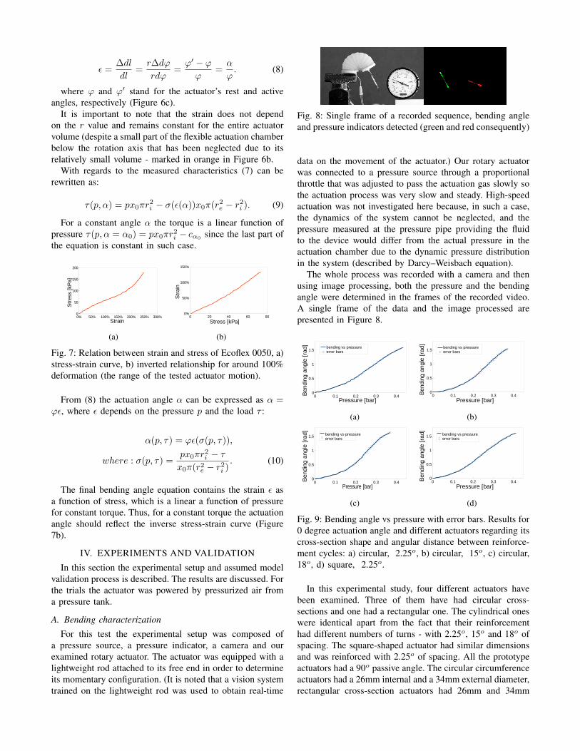
For this test the experimental setup was composed ofa pressure source, a pressure indicator, a camera and ourexamined rotary actuator. The actuator was equipped with alightweight rod attached to its free end in order to determineits momentary configuration. (It is noted that a vision systemtrained on the lightweight rod was used to obtain real-time
Fig. 8: Single frame of a recorded sequence, bending angleand pressure indicators detected (green and red consequently)
data on the movement of the actuator.) Our rotary actuatorwas connected to a pressure source through a proportionalthrottle that was adjusted to pass the actuation gas slowly sothe actuation process was very slow and steady. High-speedactuation was not investigated here because, in such a case,the dynamics of the system cannot be neglected, and thepressure measured at the pressure pipe providing the fluidto the device would differ from the actual pressure in theactuation chamber due to the dynamic pressure distributionin the system (described by Darcy–Weisbach equation).
The whole process was recorded with a camera and thenusing image processing, both the pressure and the bendingangle were determined in the frames of the recorded video.A single frame of the data and the image processed arepresented in Figure 8.
0 0.1 0.2 0.3 0.40
0.5
1
1.5
Pressure [bar]
Ben
ding
ang
le [
rad] bending vs pressure
error bars
(a)
0 0.1 0.2 0.3 0.40
0.5
1
1.5
Pressure [bar]
Ben
ding
ang
le [
rad] bending vs pressure
error bars
(b)
0 0.1 0.2 0.3 0.40
0.5
1
1.5
Pressure [bar]
Ben
ding
ang
le [
rad] bending vs pressure
error bars
(c)
0 0.1 0.2 0.3 0.40
0.5
1
1.5
Pressure [bar]
Ben
ding
ang
le [
rad] bending vs pressure
error bars
(d)
Fig. 9: Bending angle vs pressure with error bars. Results for0 degree actuation angle and different actuators regarding itscross-section shape and angular distance between reinforce-ment cycles: a) circular, 2.25o, b) circular, 15o, c) circular,18o, d) square, 2.25o.
In this experimental study, four different actuators havebeen examined. Three of them have had circular cross-sections and one had a rectangular one. The cylindrical oneswere identical apart from the fact that their reinforcementhad different numbers of turns - with 2.25o, 15o and 18o ofspacing. The square-shaped actuator had similar dimensionsand was reinforced with 2.25o of spacing. All the prototypeactuators had a 90o passive angle. The circular circumferenceactuators had a 26mm internal and a 34mm external diameter,rectangular cross-section actuators had 26mm and 34mm
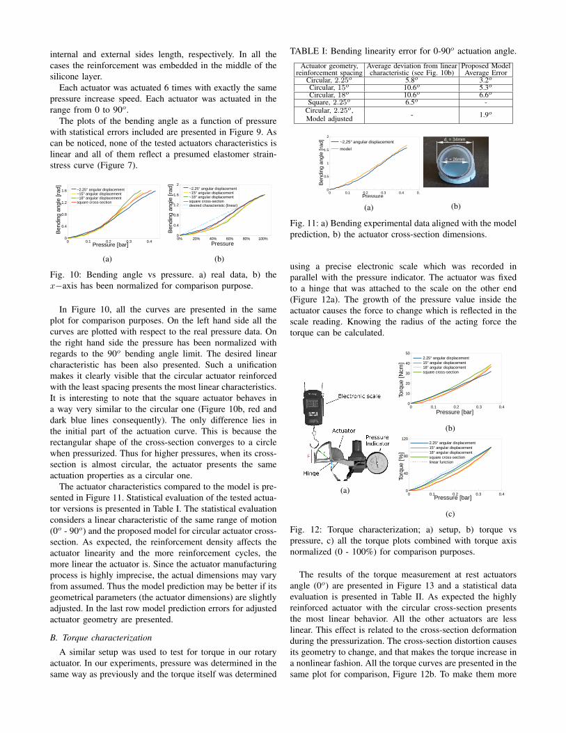
internal and external sides length, respectively. In all thecases the reinforcement was embedded in the middle of thesilicone layer.
Each actuator was actuated 6 times with exactly the samepressure increase speed. Each actuator was actuated in therange from 0 to 90o.
The plots of the bending angle as a function of pressurewith statistical errors included are presented in Figure 9. Ascan be noticed, none of the tested actuators characteristics islinear and all of them reflect a presumed elastomer strain-stress curve (Figure 7).
0 0.1 0.2 0.3 0.40
0.4
0.8
1.2
1.6
Pressure [bar]
Ben
ding
ang
le [
rad] ~2.25° angular displacement
~15° angular displacement ~18° angular displacement square cross-section
(a)
0% 20% 40% 60% 80% 100%0
0.4
0.8
1.2
1.6
2
Pressure
Ben
ding
ang
le [
rad] ~2.25° angular displacement
~15° angular displacement ~18° angular displacement square cross-sectiondesired characteristic (linear)
(b)
Fig. 10: Bending angle vs pressure. a) real data, b) thex−axis has been normalized for comparison purpose.
In Figure 10, all the curves are presented in the sameplot for comparison purposes. On the left hand side all thecurves are plotted with respect to the real pressure data. Onthe right hand side the pressure has been normalized withregards to the 90o bending angle limit. The desired linearcharacteristic has been also presented. Such a unificationmakes it clearly visible that the circular actuator reinforcedwith the least spacing presents the most linear characteristics.It is interesting to note that the square actuator behaves ina way very similar to the circular one (Figure 10b, red anddark blue lines consequently). The only difference lies inthe initial part of the actuation curve. This is because therectangular shape of the cross-section converges to a circlewhen pressurized. Thus for higher pressures, when its cross-section is almost circular, the actuator presents the sameactuation properties as a circular one.
The actuator characteristics compared to the model is pre-sented in Figure 11. Statistical evaluation of the tested actua-tor versions is presented in Table I. The statistical evaluationconsiders a linear characteristic of the same range of motion(0o - 90o) and the proposed model for circular actuator cross-section. As expected, the reinforcement density affects theactuator linearity and the more reinforcement cycles, themore linear the actuator is. Since the actuator manufacturingprocess is highly imprecise, the actual dimensions may varyfrom assumed. Thus the model prediction may be better if itsgeometrical parameters (the actuator dimensions) are slightlyadjusted. In the last row model prediction errors for adjustedactuator geometry are presented.
B. Torque characterization
A similar setup was used to test for torque in our rotaryactuator. In our experiments, pressure was determined in thesame way as previously and the torque itself was determined
TABLE I: Bending linearity error for 0-90o actuation angle.
Actuator geometry,reinforcement spacing
Average deviation from linearcharacteristic (see Fig. 10b)
Proposed ModelAverage Error
Circular, 2.25o 5.8o 3.2oCircular, 15o 10.6o 5.3oCircular, 18o 10.6o 6.6oSquare, 2.25o 6.5o -
Circular, 2.25o,Model adjusted - 1.9o
0 0.1 0.2 0.3 0.4 0.50
0.5
1
1.5
2
~2,25° angular displacement
model
Pressure
Ben
ding
ang
le [
rad]
(a)
di = 26mm
de = 34mm
(b)
Fig. 11: a) Bending experimental data aligned with the modelprediction, b) the actuator cross-section dimensions.
using a precise electronic scale which was recorded inparallel with the pressure indicator. The actuator was fixedto a hinge that was attached to the scale on the other end(Figure 12a). The growth of the pressure value inside theactuator causes the force to change which is reflected in thescale reading. Knowing the radius of the acting force thetorque can be calculated.
(a)
0 0.1 0.2 0.3 0.40
10
20
30
40
502.25° angular displacement15° angular displacement18° angular displacementsquare cross-section
Pressure [bar]
Torq
ue [
Ncm
]
(b)
0 0.1 0.2 0.3 0.40
40
80
1202.25° angular displacement15° angular displacement18° angular displacementsquare cross-sectionlinear function
Pressure [bar]
Torq
ue [
%]
(c)
Fig. 12: Torque characterization; a) setup, b) torque vspressure, c) all the torque plots combined with torque axisnormalized (0 - 100%) for comparison purposes.
The results of the torque measurement at rest actuatorsangle (0o) are presented in Figure 13 and a statistical dataevaluation is presented in Table II. As expected the highlyreinforced actuator with the circular cross-section presentsthe most linear behavior. All the other actuators are lesslinear. This effect is related to the cross-section deformationduring the pressurization. The cross-section distortion causesits geometry to change, and that makes the torque increase ina nonlinear fashion. All the torque curves are presented in thesame plot for comparison, Figure 12b. To make them more
0 0.1 0.2 0.3 0.40
10
20
30
40
Pressure [bar]
Torq
ue [
Ncm
]
torque vs pressureerror bars
(a)
0 0.1 0.2 0.3 0.40
10
20
30
40
Pressure [bar]
Torq
ue [
Ncm
]
torque vs pressureerror bars
(b)
0 0.1 0.2 0.3 0.40
10
20
30
40
50
Pressure [bar]
Torq
ue [
Ncm
]
torque vs pressureerror bars
(c)
0 0.1 0.2 0.3 0.40
10
20
30
40
50
Pressure [bar]
Torq
ue [
Ncm
]
torque vs pressureerror bars
(d)
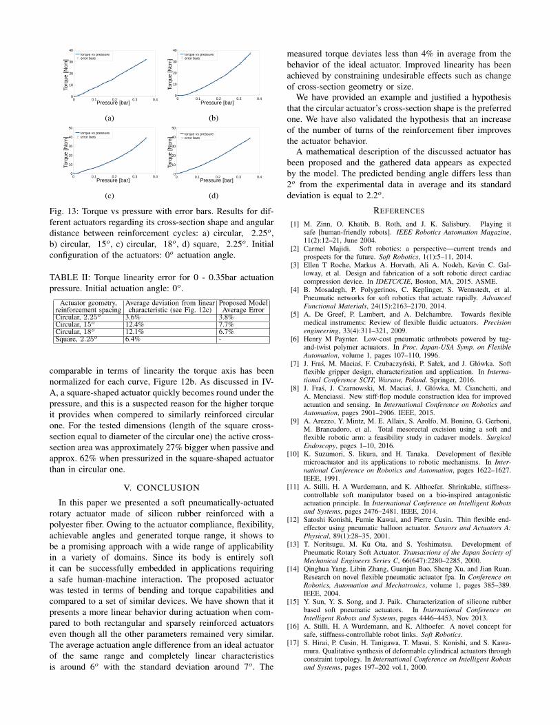
Fig. 13: Torque vs pressure with error bars. Results for dif-ferent actuators regarding its cross-section shape and angulardistance between reinforcement cycles: a) circular, 2.25o,b) circular, 15o, c) circular, 18o, d) square, 2.25o. Initialconfiguration of the actuators: 0o actuation angle.
TABLE II: Torque linearity error for 0 - 0.35bar actuationpressure. Initial actuation angle: 0o.
Actuator geometry,reinforcement spacing
Average deviation from linearcharacteristic (see Fig. 12c)
Proposed ModelAverage Error
Circular, 2.25o 3.6% 3.8%Circular, 15o 12.4% 7.7%Circular, 18o 12.1% 6.7%Square, 2.25o 6.4% -
comparable in terms of linearity the torque axis has beennormalized for each curve, Figure 12b. As discussed in IV-A, a square-shaped actuator quickly becomes round under thepressure, and this is a suspected reason for the higher torqueit provides when compered to similarly reinforced circularone. For the tested dimensions (length of the square cross-section equal to diameter of the circular one) the active cross-section area was approximately 27% bigger when passive andapprox. 62% when pressurized in the square-shaped actuatorthan in circular one.
V. CONCLUSION
In this paper we presented a soft pneumatically-actuatedrotary actuator made of silicon rubber reinforced with apolyester fiber. Owing to the actuator compliance, flexibility,achievable angles and generated torque range, it shows tobe a promising approach with a wide range of applicabilityin a variety of domains. Since its body is entirely softit can be successfully embedded in applications requiringa safe human-machine interaction. The proposed actuatorwas tested in terms of bending and torque capabilities andcompared to a set of similar devices. We have shown that itpresents a more linear behavior during actuation when com-pared to both rectangular and sparsely reinforced actuatorseven though all the other parameters remained very similar.The average actuation angle difference from an ideal actuatorof the same range and completely linear characteristicsis around 6o with the standard deviation around 7o. The
measured torque deviates less than 4% in average from thebehavior of the ideal actuator. Improved linearity has beenachieved by constraining undesirable effects such as changeof cross-section geometry or size.
We have provided an example and justified a hypothesisthat the circular actuator’s cross-section shape is the preferredone. We have also validated the hypothesis that an increaseof the number of turns of the reinforcement fiber improvesthe actuator behavior.
A mathematical description of the discussed actuator hasbeen proposed and the gathered data appears as expectedby the model. The predicted bending angle differs less than2o from the experimental data in average and its standarddeviation is equal to 2.2o.
REFERENCES
[1] M. Zinn, O. Khatib, B. Roth, and J. K. Salisbury. Playing itsafe [human-friendly robots]. IEEE Robotics Automation Magazine,11(2):12–21, June 2004.
[2] Carmel Majidi. Soft robotics: a perspective—current trends andprospects for the future. Soft Robotics, 1(1):5–11, 2014.
[3] Ellen T Roche, Markus A. Horvath, Ali A. Nodeh, Kevin C. Gal-loway, et al. Design and fabrication of a soft robotic direct cardiaccompression device. In IDETC/CIE, Boston, MA, 2015. ASME.
[4] B. Mosadegh, P. Polygerinos, C. Keplinger, S. Wennstedt, et al.Pneumatic networks for soft robotics that actuate rapidly. AdvancedFunctional Materials, 24(15):2163–2170, 2014.
[5] A. De Greef, P. Lambert, and A. Delchambre. Towards flexiblemedical instruments: Review of flexible fluidic actuators. Precisionengineering, 33(4):311–321, 2009.
[6] Henry M Paynter. Low-cost pneumatic arthrobots powered by tug-and-twist polymer actuators. In Proc. Japan-USA Symp. on FlexibleAutomation, volume 1, pages 107–110, 1996.
[7] J. Fras, M. Macias, F. Czubaczynski, P. Sałek, and J. Główka. Softflexible gripper design, characterization and application. In Interna-tional Conference SCIT, Warsaw, Poland. Springer, 2016.
[8] J. Fras, J. Czarnowski, M. Macias, J. Główka, M. Cianchetti, andA. Menciassi. New stiff-flop module construction idea for improvedactuation and sensing. In International Conference on Robotics andAutomation, pages 2901–2906. IEEE, 2015.
[9] A. Arezzo, Y. Mintz, M. E. Allaix, S. Arolfo, M. Bonino, G. Gerboni,M. Brancadoro, et al. Total mesorectal excision using a soft andflexible robotic arm: a feasibility study in cadaver models. SurgicalEndoscopy, pages 1–10, 2016.
[10] K. Suzumori, S. Iikura, and H. Tanaka. Development of flexiblemicroactuator and its applications to robotic mechanisms. In Inter-national Conference on Robotics and Automation, pages 1622–1627.IEEE, 1991.
[11] A. Stilli, H. A Wurdemann, and K. Althoefer. Shrinkable, stiffness-controllable soft manipulator based on a bio-inspired antagonisticactuation principle. In International Conference on Intelligent Robotsand Systems, pages 2476–2481. IEEE, 2014.
[12] Satoshi Konishi, Fumie Kawai, and Pierre Cusin. Thin flexible end-effector using pneumatic balloon actuator. Sensors and Actuators A:Physical, 89(1):28–35, 2001.
[13] T. Noritsugu, M. Ku Ota, and S. Yoshimatsu. Development ofPneumatic Rotary Soft Actuator. Transactions of the Japan Society ofMechanical Engineers Series C, 66(647):2280–2285, 2000.
[14] Qinghua Yang, Libin Zhang, Guanjun Bao, Sheng Xu, and Jian Ruan.Research on novel flexible pneumatic actuator fpa. In Conference onRobotics, Automation and Mechatronics, volume 1, pages 385–389.IEEE, 2004.
[15] Y. Sun, Y. S. Song, and J. Paik. Characterization of silicone rubberbased soft pneumatic actuators. In International Conference onIntelligent Robots and Systems, pages 4446–4453, Nov 2013.
[16] A. Stilli, H. A Wurdemann, and K. Althoefer. A novel concept forsafe, stiffness-controllable robot links. Soft Robotics.
[17] S. Hirai, P. Cusin, H. Tanigawa, T. Masui, S. Konishi, and S. Kawa-mura. Qualitative synthesis of deformable cylindrical actuators throughconstraint topology. In International Conference on Intelligent Robotsand Systems, pages 197–202 vol.1, 2000.