Embed Size (px)
Citation preview

Soft X-ray Telescope X-ray mirrors and CCD detectors
By S.Amruthavalli Under the guidance of Prof. K.P.Singh DAA

My Project
• Fabrication of X-ray mirrors: Sputtering
• Interfacing RAM with FPGA.

Contents of Presentation
Introduction
X-ray mirrorsTheory of X-ray reflectionProcess of fabricationSputtering
CCD DetectorsIntroduction to CCDFPGAInterfacing RAM and FPGA
References

Introduction SOFT X-RAY TELESCOPE ( SXT):
• SXT is one of the scientific instruments onboard ASTROSAT.
• A grazing incidence X-ray Telescope
Mirror assembly X-ray CCD at the focus.

Theory of X-RAYGrazing Incidence Reflection
n = 1 - d - ib
d = No Zre p λ2
A 2π
By Snell’s Law
cos αt = 1-d (αt is the grazing angle)
For d<<1, αt = √2dIf Z/A ~ 0.5 then
αt = 5.6 λ √ p

Wolter I type configuration

Theory of X-RAYs (contd.)Imaging of X-rays:
• Conical Approximation to Wolter type I:
Paraboloid (1-alpha) + Hyperboloid (3-alpha)

SXT: A Schematic Overview

X-RAY Mirror Fabrication
STEP 1 : Substrate formation

X-RAY Mirror Fabrication STEP 2 : Glass Coating

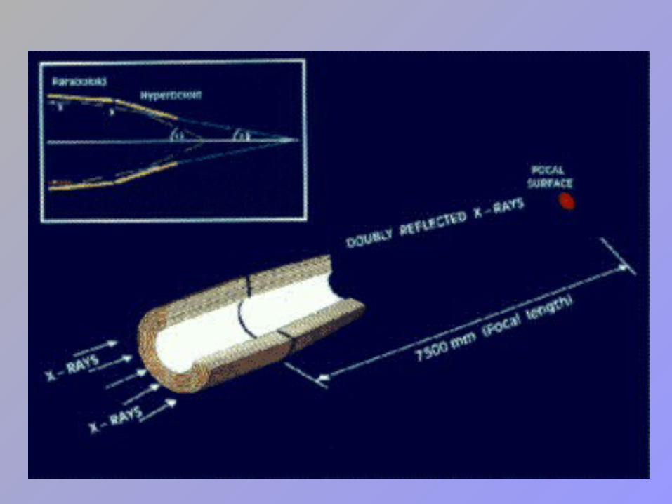
X-RAY Mirror Fabrication STEP 3 : Replication
X-RAY Mirror Fabrication STEP 3 : Replication (contd.)

SPUTTERING

SPUTTERING (contd.)A DC Sputtering system

SPUTTERING (contd.)
Some important aspects:
1) Argon gas
2) Pressure Range : 30-120 mtorr
3) Voltage range : 500V to 5000V

CCD detector
EEV CCD22 IMAGE REGION: Imaging area : ~ 2.4 X 2.4 cm. 600 X 602 array of 40µm X 40µm pixels
STORAGE REGION: 600 X 602 pixel array of 39 X 12µm pitch.
OPERATING MODE: Photon counting mode

Schematic of CCD

SXT Electronics Block Diagram
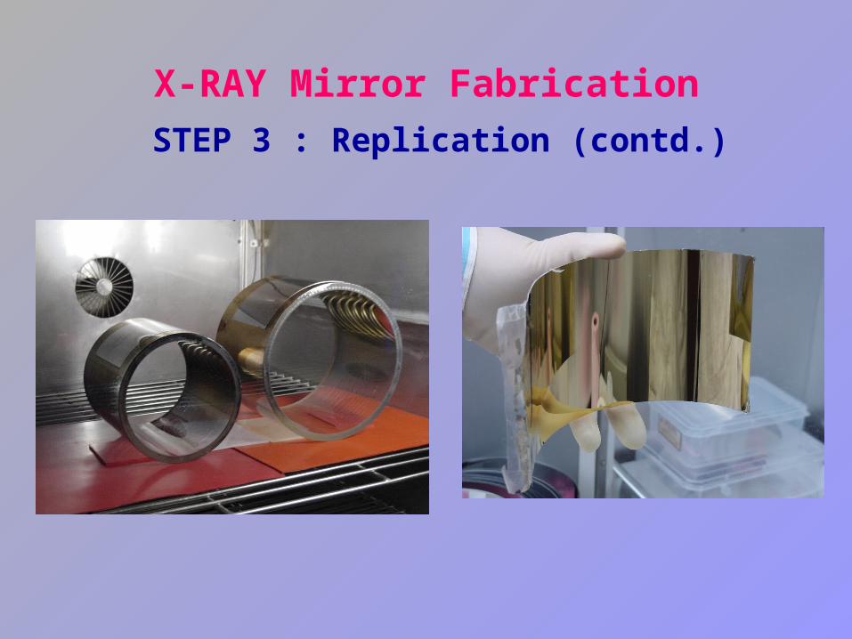
FPGA: Actel ProAsic Plus APA150General Structure

Interfacing RAM with FPGA
Need? FPGA used: Actel ProAsic Plus APA150. RAM used: HM6264 (8k) Need for buffer and Latch

Hardware circuit
Softwares used
Microcontroller: Programming MC: Labtool
FPGA: Program: Libero (Verilog HDL)
Hardware: PROTEL DXP
Programming FPGA: Actel Flash pro

CONCLUSION
1) I was involved in sputtering of 15 glass mandrels out of which in 9 the gold was transferred successfully onto Al foils.
2) RAM was first interfaced with Microcontroller. The hardware and software was tested. Later the program was adopted for FPGA using Verilog HDL and the hardware was designed in PROTEL.

REFERENCES
B Aschenbach in “Reports of Progress in Physics” (1985).
Report on “Laboratory X-ray CCD camera electronics” by Department of Astrophysics, The Pennsylvania State University.
“Glow Discharge Process” by Brian Chapman

Acknowledgements
• I am extremely grateful to Prof K.P. Singh for his invaluable guidance. I am obliged to have worked under him encouraged me to do develop a pragmatic approach to whatever I do.
• I also wish to thank Ms. Nisha Yadav who patiently taught me the process of X-ray mirror fabrication. I am thankful to Mr. Dinesh Gupta who helped me through out in the electronics part. I am also thankful to Mr. Irfan who helped me debug the programs.

THANK YOU